Gateway to Space ASEN/ASTR 2500 Fall 2011 Colorado Space Grant Consortium Gateway to Space Fall 2011 Design Document R3D3 Written by: Tyler Smith Marisa Antuna Kate Kennedy Nicole Ela Greg McQuie Devon Campbell Page 1 of 32 Nov 04, 2011 Rev C
The mission is to design, build and launch a BalloonSat which will test and compare two types of energy generation systems. For the science component, the first system will involve solar panels harnessing light energy at various altitudes and measuring the power output. This will provide data on the effectiveness of solar panels on BalloonSats and other near-space crafts. We will then compare this data to the power generated by a propeller connected to a DC generator and mounted on the side of the BalloonSat. The data from the propeller will demonstrate the viability of utilizing wind power on aircraft that remain within Earth’s atmosphere. A comparison of the two data sets will also allow for an analysis of overall efficiency of the systems.
According to the European Space Agency, “The sun is a very powerful, clean and convenient source of power, specifically for satellites”1
that first came into usage in space with the 1958 Vanguard satellite. However, “the solar arrays needed by an average-sized satellite are quite large, due to the rather low efficiency of the individual solar cells.”2
Due to the small size and surface area of a BalloonSat, a power system based off of solar panels may not represent the most affective method. Furthermore, according to the U.S. Energy Information Administration, wind power is the fastest growing source of power.3
While on a normal satellite wind is not a viable source of power, due to lack of atmosphere, a propeller is a possibility for a BalloonSat. During the BalloonSat’s movement through the lower atmospheric layers, there will be enough air to spin the propeller thereby generating energy. Our team proposes to do a comparison of these two types of power systems in order to determine the most effective technique for use on subsequent BalloonSats and potentially other near-Earth satellites.
Current and voltage data will be collected at various altitudes so that a comprehensive comparison of the two systems can be conducted. Essentially, the energy gathered over the period of the flight by both systems will be charted against the altitude. This will determine in what environments the systems are most effective. Furthermore looking at the systems’ charts together will allow us to discover whether the solar system or propeller system is most efficient overall. We shall also be able to discover which power generation type puts out more power at various altitudes. This may provide evidence that both systems could be used at different times during a flight, instead of just relying on one throughout the entire flight. In this final comparison, we will also attempt to take into account other environmental factors and their effects on each system. For example, the presence of clouds could have an effect on the solar panels, and it is also important to consider varying sun angles both at different altitudes and at different times of day. This would allow future engineers to design their power systems with consideration to predicted environmental conditions in order to achieve more efficient power generation in their crafts.
Our mission’s purpose is to learn about solar and propeller power generation and better understand these systems and how to properly utilize them. The number of BalloonSat programs is increasing, and according to NASA, these programs help “attract and retain students in the areas of science, technology, engineering and mathematics.”4
Page 3 of 21 Nov 04, 2011
Rev C
Gateway to Space ASEN/ASTR 2500 Fall 2011
Due to budget cuts NASA is not able to fund such projects without knowing the risks and rewards. As BalloonSats grow in popularity, the need for more efficient power systems will grow as well. Our experiment is designed to benefit future missions.
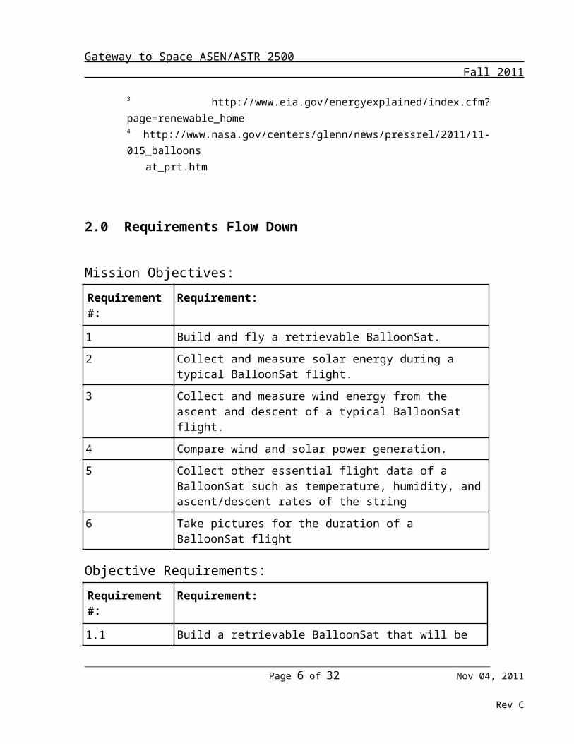
2 Collect and measure solar energy during a typical BalloonSat flight.
3 Collect and measure wind energy from the ascent and descent of a typical BalloonSat flight.
4 Compare wind and solar power generation.
5 Collect other essential flight data of a BalloonSat such as temperature, humidity, and ascent/descent rates of the string
6 Take pictures for the duration of a BalloonSat flight
Objective Requirements:
Requirement #: Requirement:
1.1 Build a retrievable BalloonSat that will be able attached to a flight string of multiple BalloonSats for a launch to an altitude of approximately 30km in November 2011.
1.2 Build the BalloonSat such that it will be able to withstand the forces and energies of the entire BalloonSat flight.
1.3 Have an indicator to know upon landing that the BalloonSat is still functional
2.1 The BalloonSat will have eight solar panels, two to a side, attached
Page 4 of 21 Nov 04, 2011
Rev C
Gateway to Space ASEN/ASTR 2500 Fall 2011
to the exterior of the satellite which will gather energy from the sun.
2.2 This voltage and current of this solar energy will be measured, recorded, and stored for the duration of the flight
3.1 The BalloonSat will have a propeller attached to the top of the structure which will be attached to a generator and gather energy from the ascent and descent.
3.2 The voltage and current of this energy will be measured, recorded, and stored for the duration of the flight
4.1 Each voltage and current sensor will be interfaced to a flight computer which will interpret the readings from the sensors.
4.2 The data from the flight computer will be digitally recorded while the BalloonSat is flying
4.3 The data be retrievable from the flight computer via a wired connection after the flight is over.
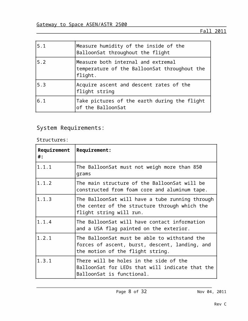
5.1 Measure humidity of the inside of the BalloonSat throughout the flight
5.2 Measure both internal and extremal temperature of the BalloonSat throughout the flight.
5.3 Acquire ascent and descent rates of the flight string
6.1 Take pictures of the earth during the flight of the BalloonSat
System Requirements:
Structures:
Requirement #: Requirement:
1.1.1 The BalloonSat must not weigh more than 850 grams
1.1.2 The main structure of the BalloonSat will be constructed from foam core and aluminum tape.
1.1.3 The BalloonSat will have a tube running through the center of the structure through which the flight string will run.
1.1.4 The BalloonSat will have contact information and a USA flag painted on the exterior.
1.2.1 The BalloonSat must be able to withstand the forces of ascent, burst, descent, landing, and the motion of the flight string.
Page 5 of 21 Nov 04, 2011
Rev C
Gateway to Space ASEN/ASTR 2500 Fall 2011
1.3.1 There will be holes in the side of the BalloonSat for LEDs that will indicate that the BalloonSat is functional.
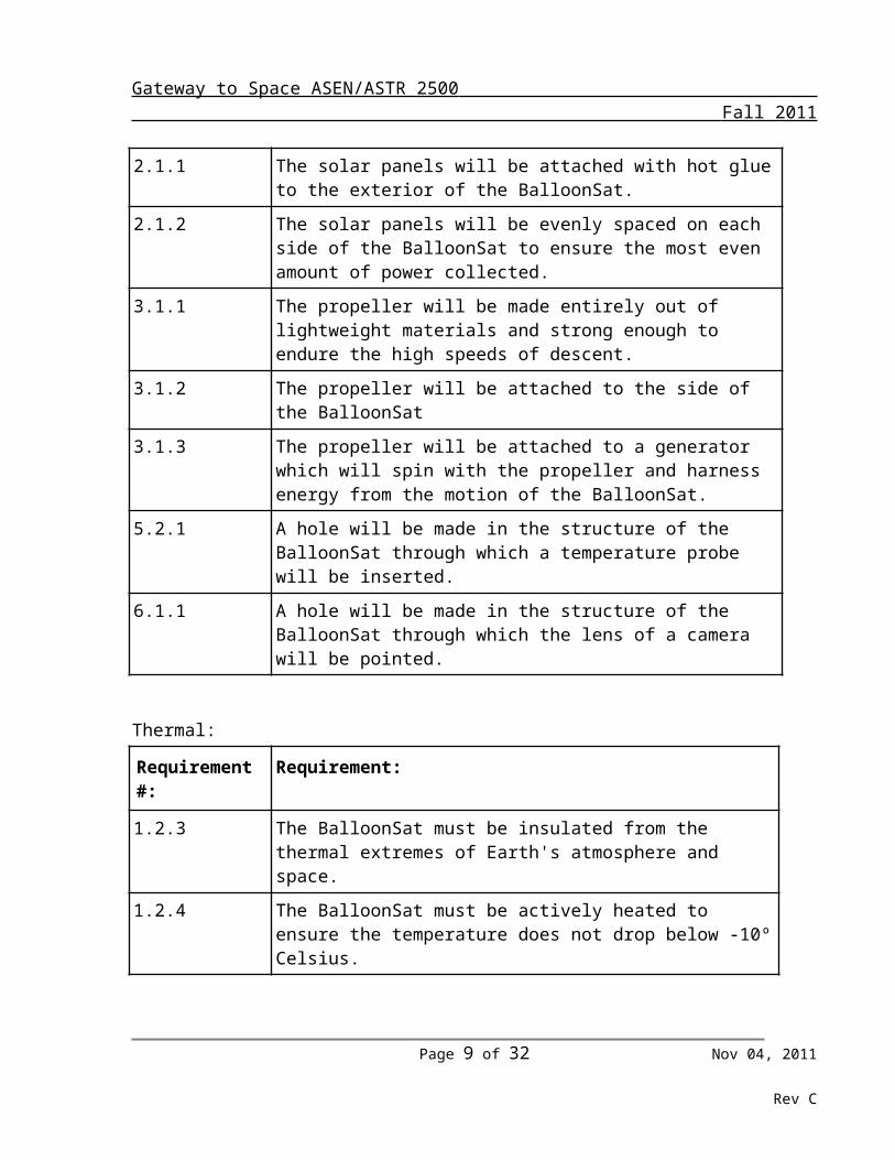
2.1.1 The solar panels will be attached with hot glue to the exterior of the BalloonSat.
2.1.2 The solar panels will be evenly spaced on each side of the BalloonSat to ensure the most even amount of power collected.
3.1.1 The propeller will be made entirely out of lightweight materials and strong enough to endure the high speeds of descent.
3.1.2 The propeller will be attached to the side of the BalloonSat
3.1.3 The propeller will be attached to a generator which will spin with the propeller and harness energy from the motion of the BalloonSat.
5.2.1 A hole will be made in the structure of the BalloonSat through which a temperature probe will be inserted.
6.1.1 A hole will be made in the structure of the BalloonSat through which the lens of a camera will be pointed.
Thermal:
Requirement #: Requirement:
1.2.3 The BalloonSat must be insulated from the thermal extremes of Earth's atmosphere and space.
1.2.4 The BalloonSat must be actively heated to ensure the temperature does not drop below -10º Celsius.
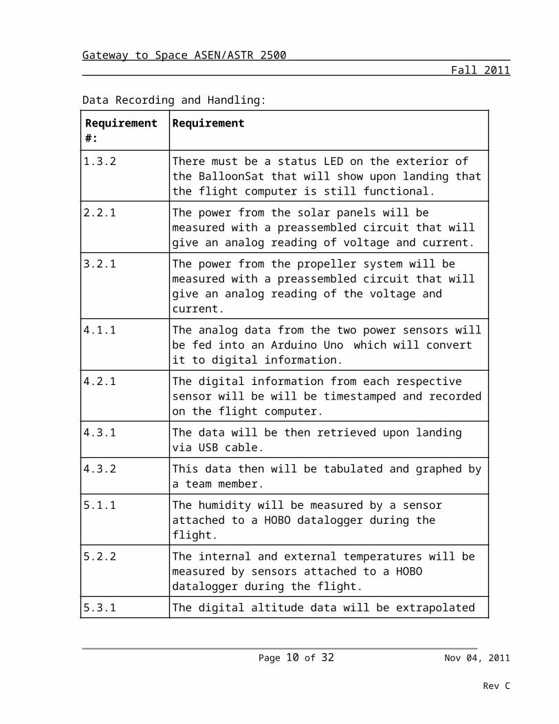
Data Recording and Handling:
Requirement #: Requirement
1.3.2 There must be a status LED on the exterior of the BalloonSat that will show upon landing that the flight computer is still functional.
2.2.1 The power from the solar panels will be measured with a preassembled circuit that will give an analog reading of voltage and current.
3.2.1 The power from the propeller system will be measured with a preassembled circuit that will give an analog reading of the voltage and current.
4.1.1 The analog data from the two power sensors will be fed into an
Page 6 of 21 Nov 04, 2011
Rev C
Gateway to Space ASEN/ASTR 2500 Fall 2011
Arduino Uno which will convert it to digital information.
4.2.1 The digital information from each respective sensor will be will be timestamped and recorded on the flight computer.
4.3.1 The data will be then retrieved upon landing via USB cable.
4.3.2 This data then will be tabulated and graphed by a team member.
5.1.1 The humidity will be measured by a sensor attached to a HOBO datalogger during the flight.
5.2.2 The internal and external temperatures will be measured by sensors attached to a HOBO datalogger during the flight.
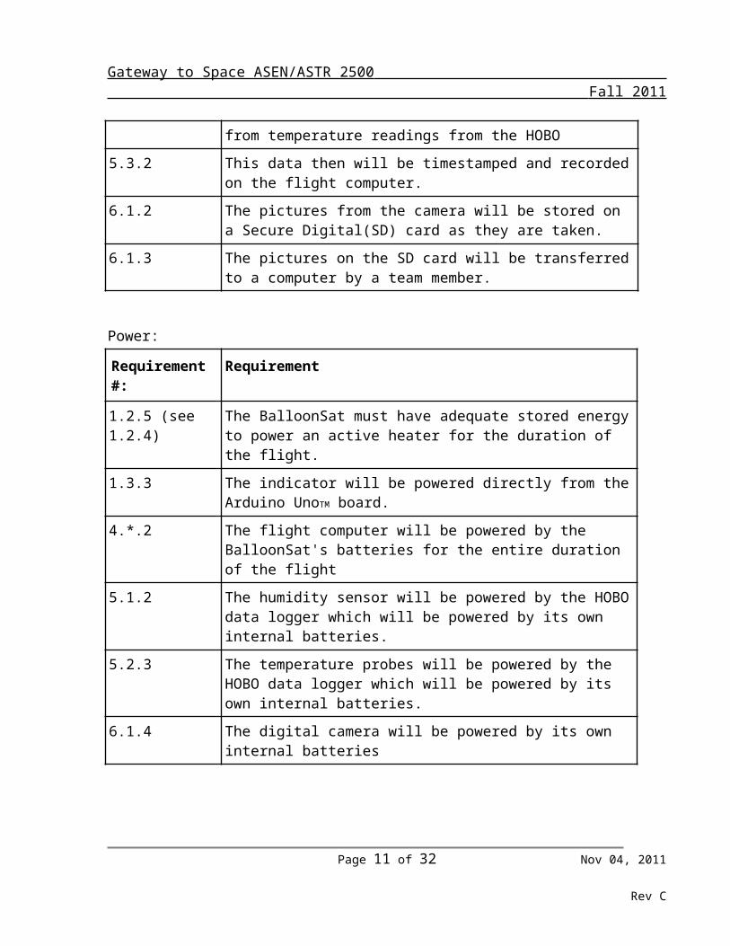
5.3.1 The digital altitude data will be extrapolated from temperature readings from the HOBO
5.3.2 This data then will be timestamped and recorded on the flight computer.
6.1.2 The pictures from the camera will be stored on a Secure Digital(SD) card as they are taken.
6.1.3 The pictures on the SD card will be transferred to a computer by a team member.
Power:
Requirement #: Requirement
1.2.5 (see 1.2.4) The BalloonSat must have adequate stored energy to power an active heater for the duration of the flight.
1.3.3 The indicator will be powered directly from the Arduino UnoTM board.
4.*.2 The flight computer will be powered by the BalloonSat's batteries for the entire duration of the flight
5.1.2 The humidity sensor will be powered by the HOBO data logger which will be powered by its own internal batteries.
5.2.3 The temperature probes will be powered by the HOBO data logger which will be powered by its own internal batteries.
6.1.4 The digital camera will be powered by its own internal batteries
Page 7 of 21 Nov 04, 2011
Rev C
Gateway to Space ASEN/ASTR 2500 Fall 2011
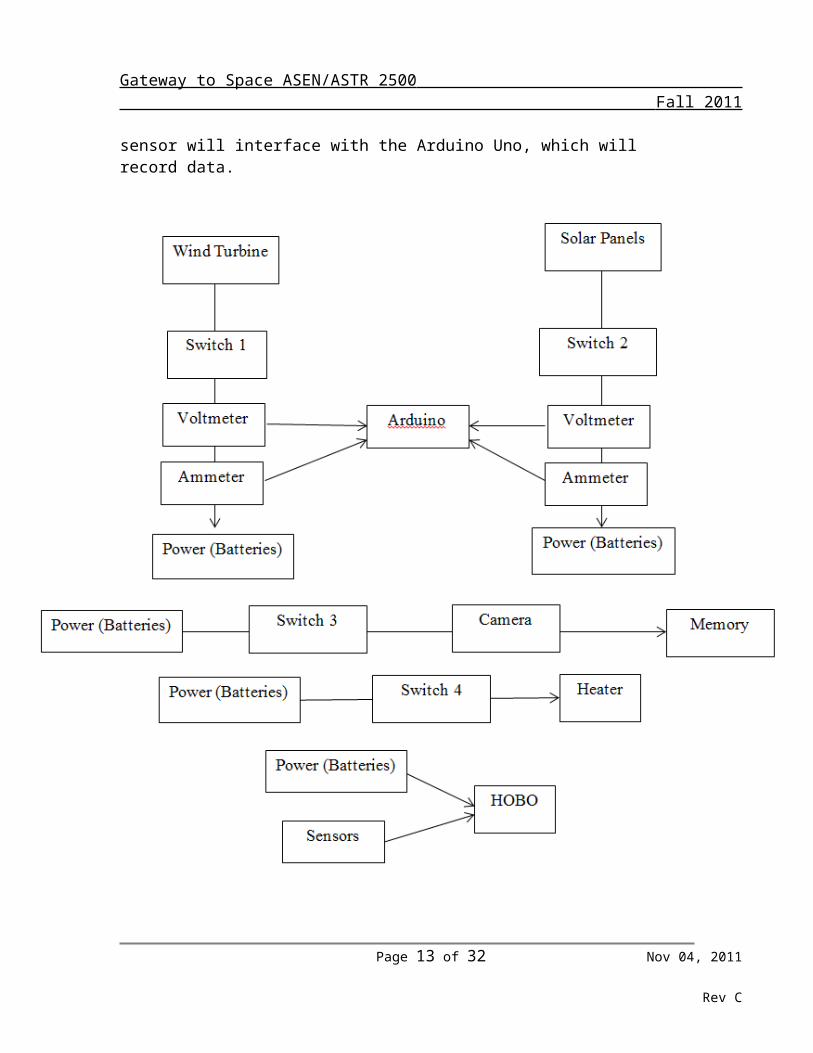
3.0 Design We are using two different systems to complete our mission of comparing methods of power generation. Our general systems include power generation systems through the propeller and solar panels, and the command and data handling system that interfaces with those two systems. The solar panels were purchased from Solarhome.org, and are self-contained units of solar cells. These will be wired to three 9-volt batteries, which will store the power generated by the solar panels. One of the Attopilot Voltage and Current Sense breakout modules will measure the voltage and current coming from the solar panels, and will interface with the Arduino board to record the data. Both of these products come from Sparkfun, and will interface through a solder connection. The power system for the propeller will consist of the propeller, a gear motor, and an Attopilot Voltage and Current sensor, which will interface with the Arduino board. We will manufacture the propeller ourselves due to the special requirements of the mission. We will construct a three-blade propeller that mimics a wind turbine. The blades will have a small chord in comparison to the blade length to ensure high efficiency in capturing wind. The blades will also be tapered to reduce induced drag at the tips, which will increase the propeller’s efficiency. The propeller will be attached to the axle of the gear motor, which will spin and generate current. The gear motor will be purchased from Servocity. The second Attopilot Voltage and Current sensor will be attached to the wire coil inside the motor, and will measure the voltage and current. This sensor will interface with the Arduino Uno, which will record data.
Page 8 of 21 Nov 04, 2011
Rev C
Gateway to Space ASEN/ASTR 2500 Fall 2011
Our BalloonSat design meets all of the requirements. Our design collects science data from a propeller system and a solar panel system that we will be able to analyze after retrieval. The flight string will run through the center of the BalloonSat, and will be properly secured so that it does not pull through the BalloonSat. The design includes a
Page 9 of 21 Nov 04, 2011
Rev C
Gateway to Space ASEN/ASTR 2500 Fall 2011
heater that will be placed strategically so that the internal temperature of the BalloonSat never dips below -10 degrees Celsius. All of our component parts weigh less that the maximum of 850 grams. Our internal design will ensure that each of our required components (ie. HOBO, temperature cable, and camera) have adequate space to perform their duties effectively. An American flag will be placed on the outside of our BalloonSat to prove to random farmers that our BalloonSat is not a UFO or terrorist attack.
Requirement Two states that we will collect solar power during our BalloonSat flight. To accomplish this mission, we will have solar panels located on three of the four sides of the BalloonSat as well as two mounted on the top. To collect the energy from the solar panels, we will have a voltmeter to read the voltage output from the panels. The voltmeter will be attached to our Arduino which Greg will program to record our data.
We also must collect and measure wind energy from a typical BalloonSat flight (Requirement Three). There will be two components. The first component is the actual propeller that will spin as the BalloonSat ascends and descends. This will spin a DC motor in reverse which then will generate electricity. This electricity then will be measured with a voltage/current sensor which is interfaced to an Arduino. The Arduino will measure this data for the duration of the flight.
The fourth requirement is the comparison between our solar panel power and our propeller power. After the mission, we will compare the data between the solar panel and the propeller by taking the information from the Arduino and transferring it to a computer. With this, we will be able to provide a description of the power differences with which we can draw a conclusion about our power generation.
Requirement Five will be met with the data recorded from the HOBO and ascent and descent data acquired after flight. The HOBO datalogger measures internal and external temperature and humidity, which will allow for the team to extrapolate the cause of any failures. The HOBO is provided by Spacegrant. We will acquire altitude data from another team that measured altitude. If no other teams measured altitude, or if they are unwilling to share their data, we will extrapolate the rate of ascent and descent from the time of flight and the external temperature data.
The last requirement will be met with the camera provided by Spacegrant. The camera comes pre-programmed to take one picture every ten seconds for the duration of the flight. This will provide our team with a number of pictures taken from various altitudes during the flight.
Page 10 of 21 Nov 04, 2011
Rev C
Gateway to Space ASEN/ASTR 2500 Fall 2011
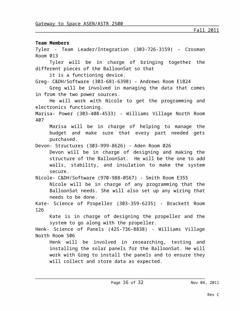
4.0 ManagementInclude an introduction paragraph to this section. Provide a chart showing how the team will be organized and who is responsible for each of the subsystems. Provide a project schedule and describe your time limitations. Items should be updated for each revision of this document.Team MembersTyler - Team Leader/Integration (303-726-3159) - Crosman Room 013
Tyler will be in charge of bringing together the different pieces of the BalloonSat so that
it is a functioning device.Greg- C&DH/Software (303-681-6398) - Andrews Room E1B24
Greg will be involved in managing the data that comes in from the two power sources.
He will work with Nicole to get the programming and electronics functioning.Marisa- Power (303-408-4533) - Williams Village North Room 407
Marisa will be in charge of helping to manage the budget and make sure that every part needed gets purchased.
Devon- Structures (303-999-8626) - Aden Room 026Devon will be in charge of designing and making the structure of the BalloonSat. He will be the one to add walls, stability, and insulation to make the system secure.
Nicole- C&DH/Software (970-988-0567) - Smith Room E355Nicole will be in charge of any programming that the BalloonSat needs. She will also set up any wiring that needs to be done.
Kate- Science of Propeller (303-359-6235) - Brackett Room 126Kate is in charge of designing the propeller and the system to go along with the propeller.
Henk- Science of Panels (425-736-8838) - Williams Village North Room 506Henk will be involved in researching, testing and installing the solar panels for the BalloonSat. He will work with Greg to install the panels and to ensure they will collect and store data as expected.
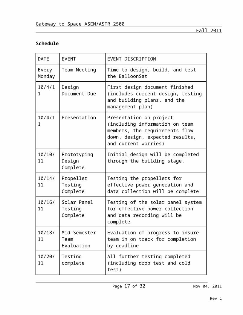
Schedule
DATE EVENT EVENT DISCRIPTION
Every Monday
Team Meeting Time to design, build, and test the BalloonSat
10/4/11 Design Document Due
First design document finished (includes current design, testing and building plans, and the management plan)
Page 11 of 21 Nov 04, 2011
Rev C
Gateway to Space ASEN/ASTR 2500 Fall 2011
10/4/11 Presentation Presentation on project (including information on team members, the requirements flow down, design, expected results, and current worries)
10/10/11 Prototyping Design Complete
Initial design will be completed through the building stage.
10/14/11 Propeller Testing Complete
Testing the propellers for effective power generation and data collection will be complete
10/16/11 Solar Panel Testing Complete
Testing of the solar panel system for effective power collection and data recording will be complete
10/18/11 Mid-Semester Team Evaluation
Evaluation of progress to insure team in on track for completion by deadline
10/20/11 Testing complete All further testing completed (including drop test and cold test)
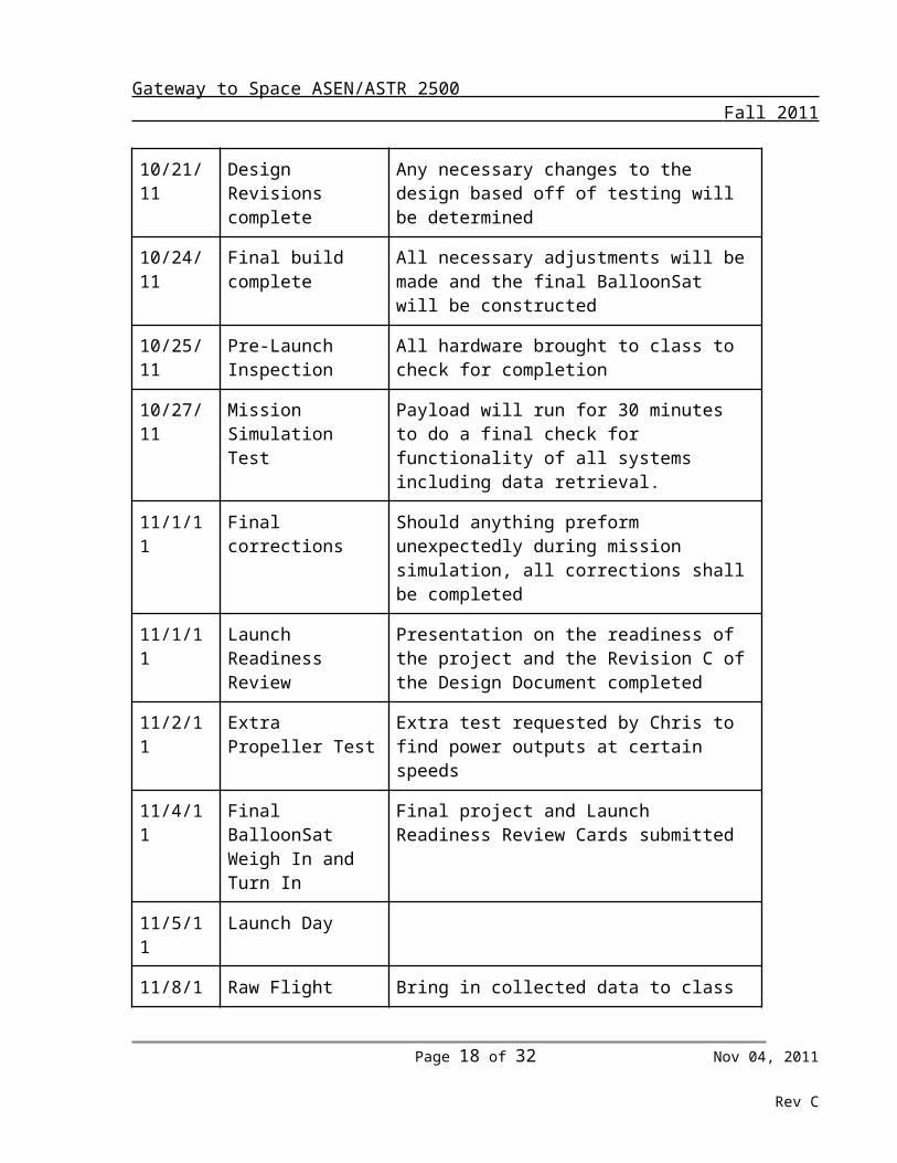
10/21/11 Design Revisions complete
Any necessary changes to the design based off of testing will be determined
10/24/11 Final build complete All necessary adjustments will be made and the final BalloonSat will be constructed
10/25/11 Pre-Launch Inspection
All hardware brought to class to check for completion
10/27/11 Mission Simulation Test
Payload will run for 30 minutes to do a final check for functionality of all systems including data retrieval.
11/1/11 Final corrections Should anything preform unexpectedly during mission simulation, all corrections shall be completed
11/1/11 Launch Readiness Review
Presentation on the readiness of the project and the Revision C of the Design Document completed
11/2/11 Extra Propeller Test Extra test requested by Chris to find power outputs at certain speeds
11/4/11 Final BalloonSat Weigh In and Turn In
Final project and Launch Readiness Review Cards submitted
Page 12 of 21 Nov 04, 2011
Rev C
Gateway to Space ASEN/ASTR 2500 Fall 2011
11/5/11 Launch Day
11/8/11 Raw Flight Data Bring in collected data to class
11/29/11 Final Presentation and Data turn in
Final Presentation covering the project and results due by 7:00 and analyzed data turned in
11/30/11 Final Presentation Final Presentation given in class
12/3/11 ITLL Design ExpoFinal Design Document Team Video
Design Expo from 9:00-4:00 Final Design Report and Team Video due
12/6/11 Hardware turned in All hardware from the BalloonSat returned
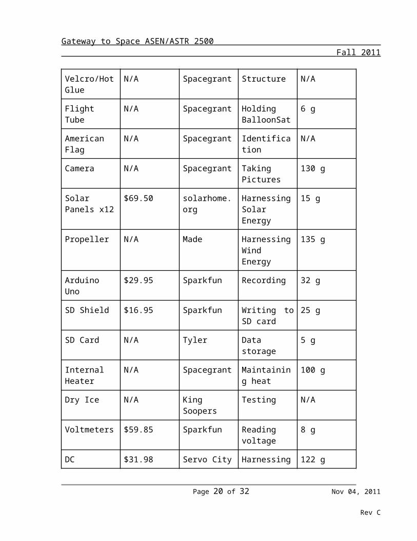
5.0 Budget
Hardware Cost Obtained From Description of Use
Weight
Foam Core N/A Spacegrant Structure 100 g
Insulation N/A Spacegrant Internal Heat 30 g
HOBO N/A Spacegrant Temp/humidity 30 g
Aluminum Tape
N/A Spacegrant Structure N/A
Xacto Knives N/A Spacegrant Cutting N/A
Velcro/Hot Glue
N/A Spacegrant Structure N/A
Flight Tube N/A Spacegrant Holding BalloonSat
6 g
American Flag N/A Spacegrant Identification N/A
Camera N/A Spacegrant Taking Pictures 130 g
Solar Panels x12
$69.50 solarhome.org Harnessing Solar Energy
15 g
Page 13 of 21 Nov 04, 2011
Rev C
Gateway to Space ASEN/ASTR 2500 Fall 2011
Propeller N/A Made Harnessing Wind Energy
135 g
Arduino Uno $29.95 Sparkfun Recording 32 g
SD Shield $16.95 Sparkfun Writing to SD card
25 g
SD Card N/A Tyler Data storage 5 g
Internal Heater N/A Spacegrant Maintaining heat
100 g
Dry Ice N/A King Soopers Testing N/A
Voltmeters $59.85 Sparkfun Reading voltage
8 g
DC Generator $31.98 Servo City Harnessing wind energy
122 g
9 Volt Battery x4
N/A Tyler Power 135 g
Total N/A 873 g
Cost management for R3D3
1.) Starting budget will allow $250 spending money. $250.00
2.) We will need 1 Arduino Pro 328 this will cost $29.95 $220.05
3.) We will need 3 Attopilot voltage + current sense-45A $19.95 each. Total $59.85 $160.20
4.) To purchase from from Sparkfun will cost an additional $2.00 for handling. $158.20
5.) We will purchase 10 Power Film solar panels 3v flexible solar panels $6.95 each, $69.50 total $88.70
6.) Shipping for solar panels will cost an additional $11.95 $76.75
7.) We purchased the gear motor from ServoCity for $31.98 $44.77
Page 14 of 21 Nov 04, 2011
Rev C
Gateway to Space ASEN/ASTR 2500 Fall 2011
8.) We purchased a MicroSD Shield for $16.95 $27.82
6.0 Test Plan and ResultsOur plan for testing will be in four main areas: experiment testing, mission
simulation testing, functional testing, and image testing. We will use these tests to troubleshoot any issues with the design of our BalloonSat so we will have a more successful flight. We will start with mission simulation testing. Once our structure is built, we will subject it to several tests to ensure the proper strength. The first test on the structure will be a test to see if it can withstand a high speed fall. This will involve dropping the structure from two or three stories to make sure that it will not break on impact with the ground or another BalloonSat. If structural integrity is lost, we will examine the structure to see what part of it failed. With this information, we will be able to build a second structure that compensates for the faults found in the first one. During this test we found that our structure can stay intact during impact with the ground. No severe damage occured and the internal systems were still working properly. Our second test will involve whirling the structure around on a one meter string at high speed to test its ability to survive in high acceleration situations (i.e. the balloon burst). Again, we will examine the structure to see where it needs fixing. With the next iteration of our BalloonSat, we will be able to ensure a structure with much greater survivability. Our third test for mission simulation testing will be a cold test. We will buy dry ice and a Styrofoam container and then we will place our BalloonSat in the dry ice and allow it to cool for an extended period of time with our heater on. After the test has concluded, we will check a thermometer inside the BalloonSat to see if it dropped below negative ten degrees Celsius at any point throughout the test. If it has not, then our heater is adequate to maintain the required temperature. If the temperature does drop too far, we must add another heater or increase the insulation on the structure so that it stays above -10 degrees Celsius. We will repeat the dry ice test until we have reached the target temperature.
The next set of testing we will do is our experiment testing. The first experiment (the one with the propeller) will need wind tunnel testing to see if it will actually spin in windy conditions. To do this we will place our BalloonSat in a wind tunnel and watch to see if it provides any spinning. If it does not, we will examine our propeller to see what component of the propeller makes it unable to spin. We will then reshape or remake this piece to ensure that the propeller spins during flight. The second test we will perform will involve the electronics. We will hook up the propeller to the DC generator and spin it. We will then get data from the voltmeter to see if it recorded any electricity generation. In the case of no data, we will look at our voltmeter as well as our DC generator to see where the energy is not transferring. We will then fix this and repeat the test until we have a functioning system.
Our other experiment will only need one test. We will place the solar panels in an area with plenty of lighting for a period of time. We will then acquire data from our voltmeter to see if any data was recorded. If no data is collected, we will check the wiring of the panels as well as the voltmeter to find the problem. Then the test will be repeated until no more problems exist with the solar panel system.
Page 15 of 21 Nov 04, 2011
Rev C
Gateway to Space ASEN/ASTR 2500 Fall 2011
The third area of testing is the image testing on the camera. With the camera mounted in the BalloonSat, we will turn it on and walk around with the BalloonSat while the camera takes pictures. We will then look at the pictures after the test to see if we got the correct number and quality of pictures. If either of these areas is deficient, we will examine the camera to see where the camera is not functioning correctly. We will fix the issue when we find its issue and test again to make sure we have fixed the problem.
Our last area of testing will be functional testing. With the completed BalloonSat, we will turn all components on and take the BalloonSat for a walk. After the walk is over, we will look at the information gathered from the BalloonSat. Each individual component will be checked to see if it functioned properly during the test while functioning with the other components. It is important that all the components work in the same environment as the others. Any problems that come up in any component will be tracked to their source and fixed. We will repeat this test until we have a fully functioning BalloonSat.
Test Results
-Whip TestThe whip test proved successful. The structure and simulated payload held up
very well, with no shifting of the payload as well as a structure that withstood the force of the whip test. There was no visible structural damage during the whip test. Pictures provided at bottom of document.
-Drop TestThis test was completed a total of two times. To simulate a payload, full cans of
soda were placed inside the cube and it was tossed off the balcony in the ITLL. The cube survived both tests with only a minor indent on one of the corners. Structurally, the cube was still capable of carrying a full payload, even with the dent in the corner. Pictures at bottom of document.
-Cold TestThe cooler test proved successful in that the interior of the Balloonsat did not drop
below -10 degrees Celsius. During the test however the exterior of the Balloonsat did not drop below -25 Celsius and as such we may redo the cooler test.
- Propeller Test The purpose of this test was to both determine the efficiency of the propeller and its functionality. We tested the propeller by attaching it to the gear motor and holding the assembly out the window of a moving car. The first test was successful, but the airflow over the side mirror on the car inhibited airflow to the propeller, causing it to spin more quickly than it should have. Subsequent tests showed that the paddle-shaped propeller blades failed to rotate because the airflow was pressuring both paddles to spin in opposite directions with equal force. The original propeller was modified to have scoops on the end of the propeller shafts to increase the surface contacted by the airflow
Page 16 of 21 Nov 04, 2011
Rev C
Gateway to Space ASEN/ASTR 2500 Fall 2011
-Solar Panel TestFor this test, we began with data collection inside a poorly lit room. We then
moved the solar panels outside, waited, and then came back inside the poorly lit room. To ensure that this test was successful, we looked at the results from the test and the graph (at the bottom of the document) showed a direct correlation between the voltage output and the intensity of the light the solar panels were experiencing.-Camera Test
Our camera has tested very positive and has now taken over 800 pictures during various stages of testing. We tested with only the camera on as well as with the camera functioning during the cold test. Both times, the camera took pictures every ten seconds. During the cold test, the battery ran out, but that was because it had not been charged since previous testing of the camera. Overall, the camera has unobstructed pictures that are clear, even when moving.
-Comprehensive TestThis test involved a cold atmosphere in which every system was running. The test ran for two hours, during which we discovered that the SD shield connected to the Arduino was malfuctioning and the gear motor was not properly soldered to the voltage sensor. We fixed these problems by resoldering the wire and taping it down. The other problem turned out to be a short between the SD shield and the Arduino, which has since been fixed. We retested by doing another full system simulation, which provided results that everything was working properly.
Expected Results
The data gathered from this experiment should provide insight into the efficiency of energy generation from both solar panels and wind turbines. For the solar panel results we expect the system to produce more energy as altitude increases. The solar panels will become more efficient at higher altitudes because of the decrease in atmospheric density. In a less dense atmosphere, fewer air molecules deflect radiation from the box, so more radiation will hit the panels at a higher altitude. Environmental factors will of course play a role though. The performance of the solar panels may be affected by the low angle of the sun at the time of launch. Since launch occurs in the early morning we expect a reduced efficiency due to the initially low sun angle. Furthermore, weather conditions such as cloud cover and humidity could effect efficiency. Cloud cover will block some potential radiation, while humidity could cause a problem higher up by causing condensation on the panels. Overall, however, we see the solar panels representing a viable source of power generation.
For the propeller results we expect the system to function most efficiently in stable flight upwards to about twelve kilometers, however the efficiency will decrease in higher altitude until stable descent resumes. This is resultant of the decrease in air density
Page 17 of 21 Nov 04, 2011
Rev C
Gateway to Space ASEN/ASTR 2500 Fall 2011
as the satellite travels upward; The BalloonSat will reach a point where the propeller system will temporarily cease to generate power due to lack of air to turn the blades. Since propellers function similar to airplane wings, greater air density increases performance as more airflow is generated over the propeller making it spin faster. Therefore, our estimate of functionality until twelve kilometers is based off of possible airplane flying heights. Considering other factors, propeller performance will be affected not only by change in altitude, but alterations in pressure and temperature that occur during the flight due to the instability of the atmosphere. The early morning launch will benefit the propeller more than the solar panels because the temperature and pressure are more stable in the morning than at other times. As the satellite approaches burst altitude, the propeller will not have enough atmosphere to cause its rotation and will likely stop generating power. We then expect power generation to resume following the parachute deployment and the return to higher air density. At 51 feet per second, the propeller began to turn at a rate high enough to generate measurable electricity. The average ascent rate for the balloon is 18 feet per second, so the propeller will work best when enough wind is produced in the atmosphere.
In comparing the results of the two power generation systems we expect that the propellers will have the advantage initially due to the solar panels’ disadvantages in lower altitude and morning flight conditions which benefit the propellers. However, in high altitude the solar panels will provide more power as environmental conditions improve for the system and the propellers cease effectiveness in less atmosphere. Immediately following the burst we expect the solar panels to continue collection but we predict the propellers will collect very little due to lack of atmosphere and erratic string movement. Following the parachute deploying, we expect the propellers to begin power generation once again making the results of the solar panels and the propellers comparable.
In order to ensure accurate data gathering we will conduct tests on both the solar panel and propeller systems. The solar panel data collection will be tested by placing the panels in the sun for a period of time comparable to the estimated flight time. We will then retrieve the data from the system and compare it to the solar index to insure the procedure runs correctly and gathers accurate data. For the propellers we will utilize a wind tunnel for testing. We will place the propeller system in a wind tunnel for the estimated flight time and then retrieve the test data. Due to the varying wind speeds that the propellers will face during flight we will run multiple tests in the wind tunnel at different speeds so we can insure data can be recorded under various conditions.
Page 18 of 21 Nov 04, 2011
Rev C
Gateway to Space ASEN/ASTR 2500 Fall 2011
Test Pictures:
Drop Test
Whip Test:
Cold Test:
Page 19 of 21 Nov 04, 2011
Rev C
Gateway to Space ASEN/ASTR 2500 Fall 2011
Propeller Test:
Solar Panel Test:
Camera Test:
Page 20 of 21 Nov 04, 2011
Rev C
Gateway to Space ASEN/ASTR 2500 Fall 2011
Comprehensive Test:
Launch PlanFor our launch plan, Tyler will ensure all elements of the BalloonSat are on and
running prior to launch and Greg will be in charge of the actual launch of the BalloonSat. Our team all plans on being present for the retrieval process. After we retrieve our BalloonSat we will recover the data. This process will be done through removing the SD card and moving the data collected from the power generation systems to a computer. Furthermore, we will retrieve temperature and humidity data from the HOBO by connecting it with the computer. We have tested both these data retrieval steps during launch readiness testing and individual tests. Taking data from the SD card was tested by running the solar panel systems and turning the propeller and then connecting the SD card with the computer. We successfully read the data off the SD card. To test the data retrieval from the HOBO we used the cold test. We ran the HOBO during the cold test, then connected it to the computer and successfully retrieved and graphed the data.