-Chapter 11. Shafting and propellers The transmission system on a ship transmits power from the engine to the propeller. It is made up of shafts, bearings, and finally the propeller itself. The thrust from the propeller is transferred to the ship through the transmission system. The different items in the system include the thrust shaft, one or more intermediate shafts and the tailshaft. These shafts are supported by the thrust block, intermediate bearings and the sierntube bearing. A sealing arrangement is provided at either end of the tailshaft with the propeller and cone completing the arrangement. These parts, their location and purpose are shown in Figure 11.1. Thrust block The thrust block transfers the ih-usi from the propeller 10 the hull o; the ship. It must therefore be soiiaiv constructed arid mounted onto a rigid seating or framework to perform its task. It may be an independent unit or an integral part of the main propulsion engine. Both ahead and astern thrusts must be catered for and the construction must be strong enough to withstand normal and shock loads. The casing of the independent thrust block is in two halves which are joined b\ fitted b-Jiis (Figure 11.2). The thrust loading is carried by bearing pads which are arranged to pivot or lilt. The pads are mounted in holders or carriers and faced with while metal. In the arrangement shown the thrust pads extend threequariers of the distance around the collar and transmit all thrust to the lower half of the casing. Other designs employ a complete ring of pads. An oil scraper deflects the oil lifted by the thrust collar and directs it onto the pad slops. From here it cascades over the thrust pads and bearings. The thrust shaft is manufactured with integral flanges for bolting to the engine or gearbox shaft and the intermediate shafting, and a thrust collar for absorbing the thrust.
Transcript
-Chapter 11.Shafting and propellers
The transmission system on a ship transmits power from the engine to the propeller. It is made up of shafts, bearings, and finally the propeller itself. The thrust from the propeller is transferred to the ship through the transmission system.
The different items in the system include the thrust shaft, one or more intermediate shafts and the tailshaft. These shafts are supported by the thrust block, intermediate bearings and the sierntube bearing. A sealing arrangement is provided at either end of the tailshaft with the propeller and cone completing the arrangement. These parts, their location and purpose are shown in Figure 11.1.
Thrust block
The thrust block transfers the ih-usi from the propeller 10 the hull o;the ship. It must therefore be soiiaiv constructed arid mounted onto a rigid seating or framework to perform its task. It may be an independent unit or an integral part of the main propulsion engine. Both ahead and astern thrusts must be catered for and the construction must be strong enough to withstand normal and shock loads.
The casing of the independent thrust block is in two halves which are joined b\ fitted b-Jiis (Figure 11.2). The thrust loading is carried by bearing pads which are arranged to pivot or lilt. The pads are mounted in holders or carriers and faced with while metal. In the arrangement shown the thrust pads extend threequariers of the distance around the collar and transmit all thrust to the lower half of the casing. Other designs employ a complete ring of pads. An oil scraper deflects the oil lifted by the thrust collar and directs it onto the pad slops. From here it cascades over the thrust pads and bearings. The thrust shaft is manufactured with integral flanges for bolting to the engine or gearbox shaft and the intermediate shafting, and a thrust collar for absorbing the thrust.
Where the thrust shaft is an integral pan of the engine, the casing is usually fabricated in a similar manner to the engine bedplate to which it is bolted. Pressurised lubrication from the engine lubricating oil system is provided and most other details of construction are similar to the independent type of thrust block.
Shaft bearingsShaft bearings are of two types, the aftermost tunnel bearing and all others. The aftermost tunnel bearing has a top and bottom bearing shell because it must counteract the propeller mass and take a vertical upward thrust at the forward end of the tailshaft. The other shaft bearings only support the shaft weight and thus have only lower half bearing shells.
An intermediate tunnel bearing is shown in Figure 11.3. The usual journal bush is here replaced by pivoting pads. The tilting pad is better able to carry high overloads and retain a thick oil lubrication film. Lubrication is from a bath in the lower half of the casing, and an oil thrower ring dips into the oil and carries it round the shaft as it rotates. Cooling of the bearing is by water circulating through a tube cooler in the bottom of the casing.
Stemtube bearingThe sierntube bearing serves two important purposes. It supports the tailshaft and a considerable proportion of the propeller weight. It also acts as a gland to prevent the entry of sea water to the machinery space.
Early arrangements used bearing materials such as lignum vitae (a very dense form of umber) which were lubricated by sea water. Most modern designs use an oil lubrication arrangement for a white metal lined sterntube bearing. One arrangement is shown in Figure 11.4.
Oil is pumped to the bush through external axial grooves and passes through holes on each side into internal axial passages. The oil leaves from the ends of the bush and circulates back to the pump and the cooler. One of two header tanks will provide a back pressure in the system and a period of oil supply in the event of pump failure. A low-level alarm will be fitted to each header tank.
Oil pressure in the lubrication system is higher than the static sea water head to ensure that sea water cannot enter the sterntube in the event of seal failure.
Stemtube sealsSpecial seals are fitted at the outboard and inboard ends of the tailshaft_ They are arranged to prevent the entry of sea water and also the loss of lubricating oil from the stern bearing.
204 Shafting and propellers
Older designs, usually associated with sea water lubricated stern bearings, made use of a conventional stuffing box and gland at the after bulkhead. Oil-lubricated stem bearings use either lip or radial face seals or a combination of the two.
Lip seals are shaped rings of material with a projecting lip or edge which is held in contact with a shaft to prevent oil leakage or water entry. A number of lip seals are usually fitted depending upon the particular application.
Face seals use a pair of mating radial faces to seal against leakage. One face is stationary and the other rotates. The rotating face of the after seal is usually secured to the propeller boss. The stationary face of the forward or inboard seal is the after bulkhead. A spring arrangement forces the stationary and rotating faces together.
ShaftingThere may be one or more sections of intermediate shafting between the thrust shaft and the tailshaft, depending upon the machinery space location. All shafting is manufactured from solid forged ingot steel with integral flanged couplings. The shafting sections are joined by solid forged steel fitted bolts.
The intermediate shafting has flanges at each end and may be increased in diameter where it is supported by bearings.
The propeller shaft or tailshaft has a flanged face where it joins the intermediate shafting. The other end is tapered to suit a similar taper on the propeller boss. The tapered end will also be threaded to take a nut which holds the propeller in place.
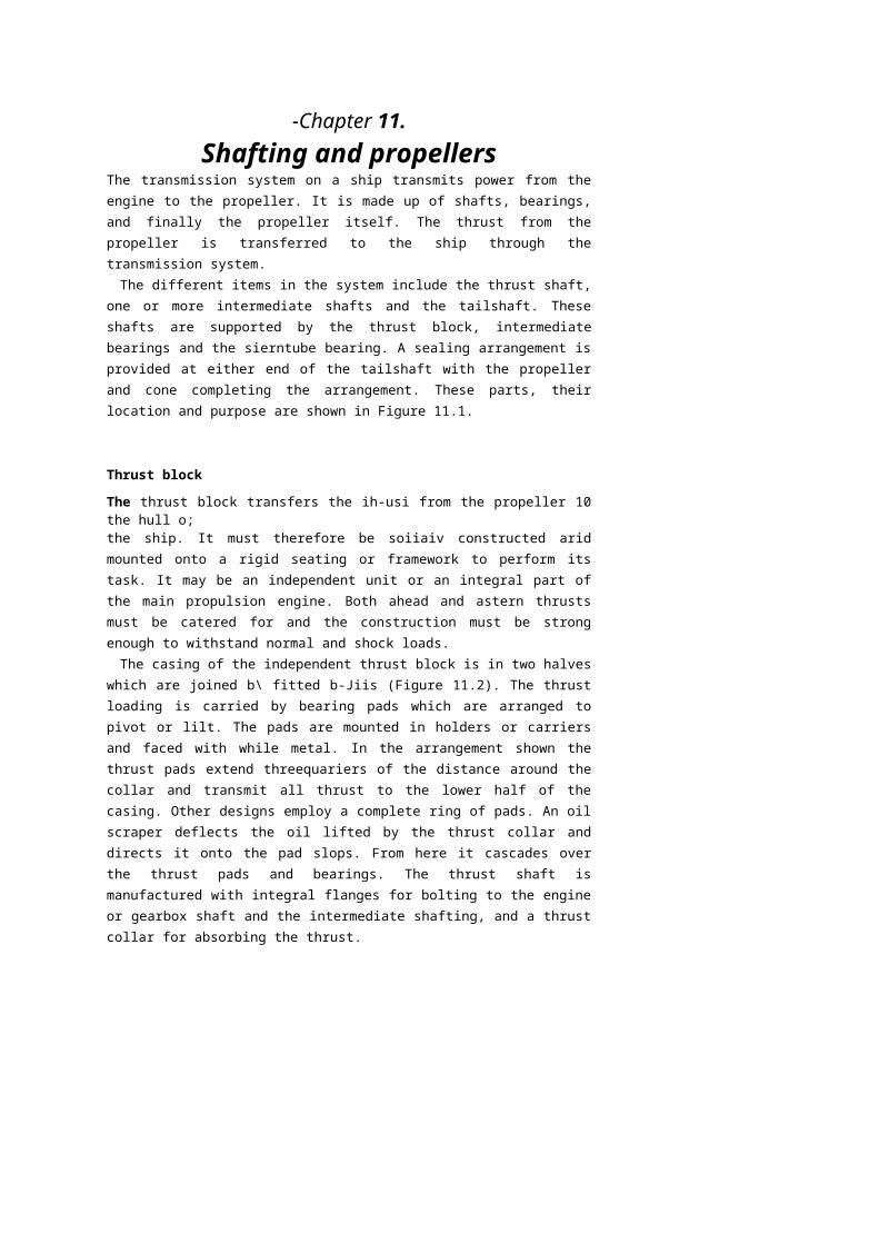
PropellerThe propeller consists of a boss with several blades of helicoidal form attached to it. When rotated it 'screws' or thrusts its way through the water by giving momentum to the column of water passing through it. The thrust is transmitted along the shafting to the thrust block and finally to the ship's structure.
A solid fixed-pitch propeller is shown in Figure 11.5. Although usually described as fixed, the pilch does vary with increasing radius from the boss. The pilch at any point is fixed, however, and for calculation purposes a mean or average value is used.
A propeller which turns clockwise when viewed from aft is considered right-handed and most single-screw ships have right-handed propellers. A twin-screw ship will usually have a right-handed starboard propeller and a left-handed port propeller.
Propeller mountingThe propeller is fitted onto a taper on the tailshaft and a key may be inserted between the two: alternatively a keyless arrangement may be used. A large nut is fastened and locked in place on the end of the tailshaft: a cone is then bolted over the end of the tailshaft to provide a smooth flow of water from the propeller.
One method of keyless propeller fitting is the oil injection system. The propeller bore has a series of axial and circumferential grooves machined into it. High-pressure oil is injected between the tapered section of the tailshaft and the propeller. This reduces the friction between the two parts and the propeller is pushed up the shaft taper by a hvdraulic jacking ring. Once the propeller is positioned the oil pressure is'released and the oil runs back, leaving the shaft and propeller securelyfastened together.
The Pilgrim Nut is a patented device which provides a predetermined frictional grip between the propeller and its shaft. With this arrangement the engine torque may be transmitted without loading the kev, where it is fitted. The Pilgrim Nut is, in effect, a threaded hydraulic jack which is screwed onto the tailshaft (Figure 11.6). A steel ring receives thrust from a hydraulically pressurised nitrile rubber tyre. This thrust is applied to the propeller to force it onto the tapered tailshaft. Propeller removal is achieved by reversing the Pilgrim Nut and using a withdrawal plate which is fastened to the propeller boss by studs. When
the tyre is pressurised the propeller is drawn off the taper. Assembly and withdrawal are shown in Figure 11.6.
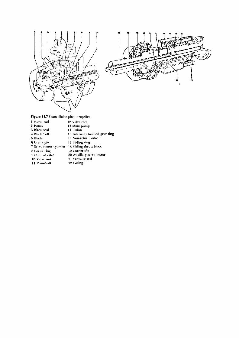
Controllable-pitch propellerA controllable-pitch propeller is made up of a boss with separate blades mounted into it. An internal mechanism enables the blades to be moved
208 Shafting and propellers
simultaneously through an arc to change the pitch angle and therefore the pitch. A typical arrangement is shown in Figure 11.7.
When a pitch demand signal is received a spool valve is operated which controls the supply of low-pressure oil to the auxiliary servo motor. The auxiliary servo motor moves the sliding thrust block assembly to position the valve rod which extends into the propeller hub. The valve rod admits high-pressure oil into one side or the other of the main servo motor cylinder. The cylinder movement is transferred by a crank pin and ring to the propeller blades. The propeller blades all rotate together until the feedback signal balances the demand signal and the low-pressure oil to the auxiliary servo motor is cut off. To enable emergency control of propeller pitch in the event of loss of power the spool valves can be operated by hand. The oil pumps are shaft driven.
The control mechanism, which is usually hydraulic, passes through the tailshaft and operation is usually from the bridge. Varying the pilch will vary the thrust provided, and since a zero pitch position exists the engine shaft may turn continuously. The blades may rotate to provide astern thrust and therefore the engine does not require to be reversed.
CavitationCavitation, the forming and bursting of vapour-filled cavities or bubbles, can occur as a result of pressure variations on the back of a propeller blade. The results are a loss of thrust, erosion of the blade surface, vibrations in the afterbody of the ship and noise. It is usually limited to high-speed heavily loaded propellers and is not a problem under normal operating conditions with a well designed propeller.
Propeller maintenanceWhen a ship is in dry dock the opportunity should be taken to thoroughly examine the propeller, and any repairs necessary should be carried out bv skilled dockyard staff.
A careful examination should be made around the blade edges for signs of cracks. Even the smallest of cracks should not be ignored as they act to increase stresses locally and can result in the loss of a blade if the propeller receives a sharp blow. Edge cracks should be welded up with suitable electrodes.
Bent blades, particularly at the tips, should receive attention as soon as possible. Except for slight deformation the application of heat will be required. This must be followed by more general heating in order to stress relieve the area around the repair.
Surface roughness caused by slight pitting can be lighdy ground out and the area polished. More serious damage should be made good by
welding and subsequent heat treatment. A temporary repair for deep pits or holes could be done with a suitable resin filler.
.Chapter 12.Steering gear
The steering gear provides a movement of the rudder in response to a signal from the bridge. The total system may be considered made up of three parts, control equipment, a power unit and a transmission to the rudder stock. The control equipment conveys a signal of desired rudder angle from the bridge and activates the power unit and transmission system until the desired angle is reached. The power unit provides the force, when required and with immediate effect, to move the rudder to the desired angle. The transmission system, the steering gear, is the means by which the movement of the rudder is accomplished.
Certain requirements must currently be met by a ship's steering system. There must be two independent means of steering, although where two identical power units are provided an auxiliary unit is not required. The power and torque capability must be such that the rudder can be swung from 35° one side to 35° the other side with the ship at maximum speed, and also the time to swing from 35° one side to 30° the other side must not exceed 28 seconds. The system must be proi-ccted from shock loading and have pipework which is exclusive to it as well as be constructed from approved materials. Control of the steering gear must be provided in the steering gear compartment.
Tankers of 10000 ton gross tonnage and upwards must have two independent steering gear control systems which are operated from the bridge. Where one fails, changeover to the other must. be immediate and achieved from the bridge position. The steering gear itself must comprise two independent systems where a failure of one results in an automatic changeover to the other within 45 seconds. Any of these failures should result in audible and visual alarms on the bridge.
Steering gears can be arranged with hydraulic control equipment known as a 'telemotor', or with electrical control equipment. The power unit may in turn be hydraulic or electrically operated. Each of these units will be considered in turn, with the hydraulic unit pump being considered first. A pump is required in the hydraulic system which can immediately pump fluid in order to provide a hydraulic force that will move the rudder. Instant response does not allow time for the pump to
Jl be switched on and therefore a constantly running pump is requiredr which pumps fluid only when required. A variable delivery pumpI provides this facility.8»1it
I •"
^- Variable delivery pumps%•^ A number of different designs of variable delivery pump exist. Each has ^ a means of altering the pump stroke so that the amount of oil displaced ^ will vary from zero to some'designed maximum value. This is achieved ; by use of a floating ring, a swash plate or a slipper pad. ^ The radial cylinder (Hele-Shaw) pump is shown in Figure 12.1. ^ Within the casing a short length of shaft drives the cylinder body which :
rotates around a central valve or tube arrangement and is supported at • the ends by ball bearings. The cylinder body is connected to the central valve arrangement by ports which lead to connections at the outer casing for the supply and delivery of oil. A number of pistons fit in the radial cylinders and are fastened to slippers by a gudgeon pin. The slippers fit into a track m the circular floating ring. This ring may rotate, being supported by ball bearings, and can also move from side to side since the
bearings are mounted in guide blocks. Two spindles which pass out of the pump casing control the movement of the ring.
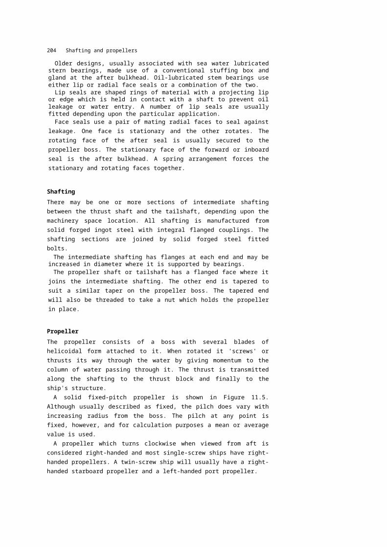
The operating principle will now be described by reference to Figure 12.2. When the circular floating ring is concentric with the central valve arrangement the pistons have no relative reciprocating motion in their cvlmaers (Figure 12.2i'a)). As a result no oil is pumped and the pump, although rotating, is not delivering any fluid. If however the circular floating ring is pulled to the right then a relative reciprocating motion of the pistons in their cylinders does occur (Figure 12.2(b)). The lower piston, for instance, as it moves inwards will discharge fluid out through the lower port in the central valve arrangement. As it continues past the horizontal position the piston moves outwards, drawing in fluid from the upper port. Once past the horizontal position on the opposite side, it begins 10 discharge the fluid. If the circular floating ring were pushed to the left then the suction and discharge ports would be reversed (Figure 12.2(c)).
This pump arrangement therefore provides, for a constantly rotating unit, a no-flow condition and infinitely variable delivery in either direction. The pump is also a positive displacement unit. Where two pumps are fitted in a system and only one is operating, reverse operation might occur. Non-reversing locking gear is provided as part of the flexible coupling and is automatic in operation. When a pump is stopped the locking gear comes into action; as the pump is started the lockingOf»T rf»\fAiifn
The swash plate and slipper pad designs are both axial cylinder pumps. The slipper pad is an improvement on the swash plate which provides higher pressure. An arrangement of a swash plate pump is shown in Figure 12.3. The driving shaft rotates the cylinder barrel, swash plate and pistons. An external trunnion (short shaft) enables the swash plate to be moved about its axis. The cylinders in the barrel are connected to ports which extend in an arc around the fixed port plate.
When the swash plate is vertical no pumping action takes place. When the swash place is tilted pumping occurs, the length of stroke depending upon the angle of tilt. Depending upon the direction of tilt the ports will be either suction or discharge. This pump arrangement therefore offers the same flexibility in operation as the radial piston type.
Telemotor control
Telemotor control is a hydraulic control system employing a transmitter, a receiver, pipes and a charging unit. The transmitter, which is built into the steering wheel console, is located on the bridge and the receiver is mounted on the steering gear. The charging unit is located near to the
The lelemoior system is shown in Figure 12.4. Two rams are present in the transmitter which move in opposite directions as the steering wheel is turned. The fluid is therefore pumped down one pipe line ano drawn in from the other. The pumped fluid passes through piping to the receiver and forces the lelemotor cylinder unit to move. The suction of fluid from the opposite cylinder enables this movement to take place. The cylinder unit has a control spindle connected to it by a pin. Itus control spindle operates the slipper ring or swash plate of the variable delivery pump. If the changeover pin is removed from the cylinder unit and inserted in the local handwheel drive then manual control of the
\^X 'S,3^- „..- r 'hand-hydraulic' Bypass shut-off cock '^^^Sc-V'T^^'.- ! position
Air valves | g^| ^3^ leve1 Superchargins chamber 'W 'VW&J B "Bt Tank drain ' |
. . ^J3'luH . » Il^^k . A Valves clo»ed. Automatic bypass and -J& qf^fi -j B • W0^' n M jy lupercharging valve n U-iy,,. _B_) R'S^.^S ^f.^
Bypass valves open | rJHJ^J--^| B^ Hand operated I^^^J^^j^^JJ^^^^^^^J circuit valve"Transmitter ; | Tele'Tiotor /''
Charging Y
^=^^ | ^^y "^'pump—^ t?——• !!^'
jQ^— ^Local control )• handwheel
|l | \ Telemotor Air valves | l./^^-pi cylinders —^« ^ B
^ •',• r1 ̂ 1 *• l '^-J^..^.^" » ,„.•^'^L "
Pipes led to [{ -g'yj^^'"""^—..—^. -.t - •_~^_^'^ pumping unit \\ L" ~~^*^'J1 ' '•=^-, ^^?•' .....—n 1^
r \^^ •'^^^i'""1''!''^^^Duplex receiver cy!?nd«r» ^^'Air valves
^^•«— T^ A T»1»mrMAr Mwrr^l tvtieni
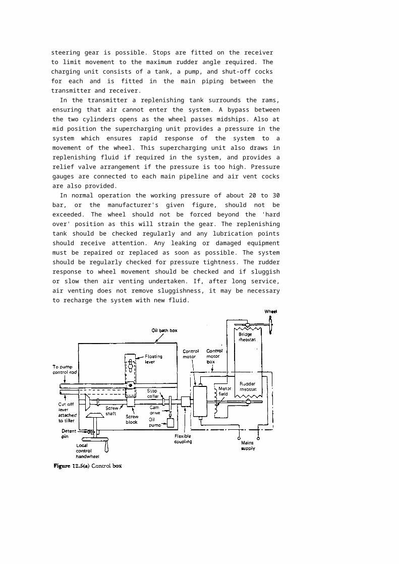
steering gear is possible. Stops are fitted on the receiver to limit movement to the maximum rudder angle required. The charging unit consists of a tank, a pump, and shut-off cocks for each and is fitted in the main piping between the transmitter and receiver.
In the transmitter a replenishing tank surrounds the rams, ensuring that air cannot enter the system. A bypass between the two cylinders opens as the wheel passes midships. Also at mid position the supercharging unit provides a pressure in the system which ensures rapid response of the system to a movement of the wheel. This supercharging unit also draws in replenishing fluid if required in the system, and provides a relief valve arrangement if the pressure is too high. Pressure gauges are connected to each main pipeline and air vent cocks are also provided.
In normal operation the working pressure of about 20 to 30 bar, or the manufacturer's given figure, should not be exceeded. The wheel should not be forced beyond the 'hard over' position as this will strain the gear. The replenishing tank should be checked regularly and any lubrication points should receive attention. Any leaking or damaged equipment must be repaired or replaced as soon as possible. The system should be regularly checked for pressure tightness. The rudder response to wheel movement should be checked and if sluggish or slow then air venting undertaken. If, after long service, air venting does not remove sluggishness, it may be necessary to recharge the system with new fluid.
Electrical control
The electrical remote control system is commonly used in modem installations since it uses a small control unit as transmitter on the bridge and is simple and reliable in operation.
The control box assembly, which is mounted on the steering gear, is shown in Figure 12.5 (a) and (b). Movement of the bridge transmitter results in electrical imbalance and current flow to the motor. The motor drives, through a flexible coupling, a screw shaft, causing it to turn. A screw block on the shaft is moved and this in turn moves the floating lever to which a control rod is attached. The control rod operates the slipper ring or swash plate of the variable delivery pump. A cut-off lever connected to the moving tiller will bring the floating lever pivot and the lever into line at right angles to the screw shaft axis. At this point the rudder angle will match the bridge lever angle and the pumping action will stop. The rotating screw shaft will have corrected the electrical imbalance and the motor will stop. For local manual control, the electrical control is switched off and a small handwheel is connected to the screw shaft. A detent pin holds the handwheel assembly clear when not in use. Rotation of the handwheel will move the floating lever and bring about rudder movement as already described.
Power units
Two types of hydraulically powered transmission units or steering gear are in common use, i-he ram and the rotary vane.
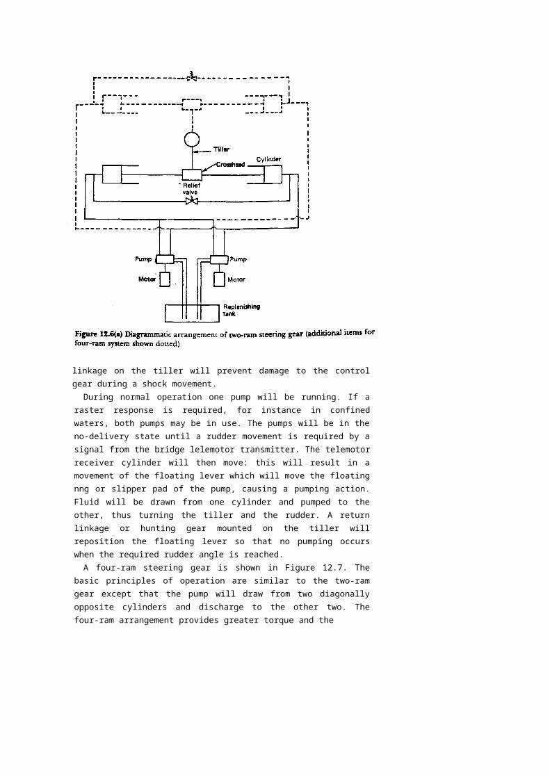
Ram typeTwo particular variations, depending upon torque requirements, are possible the two-ram and the four-ram. A two-ram steering gear is shown in Figure 12.6.
The rams acting in hydraulic cylinders operate the tiller by means of a swivel crosshead carried in a fork of the rams. A variable delivery pump is mounted on each cylinder and the slipper ring is linked by rods to the control spindle of the telemotor receiver. The variable delivery pump is piped to each cylinder to enable suction or discharge from either. A replenishing tank is mounted nearby and arranged with non-return suction valves which automatically provide make-up fluid to the pumps. A bypass valve is combined with spring-loaded shock valves which open in the event of a very heavy sea forcing the rudder over. In moving over, the pump is actuated and the steering gear will return the rudder to its original position once the heavy sea has passed. A spring-loaded return
linkage on the tiller will prevent damage to the control gear during a shock movement.During normal operation one pump will be running. If a raster response is required,
for instance in confined waters, both pumps may be in use. The pumps will be in the no-delivery state until a rudder movement is required by a signal from the bridge lelemotor transmitter. The telemotor receiver cylinder will then move: this will result in a movement of the floating lever which will move the floating nng or slipper pad of the pump, causing a pumping action. Fluid will be drawn from one cylinder and pumped to the other, thus turning the tiller and the rudder. A return linkage or hunting gear mounted on the tiller will reposition the floating lever so that no pumping occurs when the required rudder angle is reached.
A four-ram steering gear is shown in Figure 12.7. The basic principles of operation are similar to the two-ram gear except that the pump will draw from two diagonally opposite cylinders and discharge to the other two. The four-ram arrangement provides greater torque and the
flexibility of different arrangements in the event of component failure. Either pump can be used with all cylinders or with either the two port or two starboard cylinders. Various valves must be open or closed to provide these arrangements.
The use of a control valve block incorporating rudder shock relief valves, pump isolating valves, ram isolating and bypass valves, offers greater flexibility with a four-ram steering gear. In normal operation one pump can operate all cylinders. In an emergency situation the motor or a pair of hand pumps could be used to operate two port rams, two starboard rams, two forward rams or two after rams.
The crosshead arrangement on the four-ram type steering gear described incorporates what is known as the 'Rapson Slide'. This provides a mechanical advantage which increases with the angle turned through. The crosshead arrangement may use either a forked tiller or a round arm tiller (Figure 12.8). The round arm tiller has a centre crosshead which is free to slide along the tiller. Each pair of rams is joined so as to form a double bearing in which the trunnion arms of the crosshead are mounted. The straight line movement of the rams is thus convened into an angular tiller movement. In the forked tiller arrangement the ram movement is transferred to the tiller through swivel blocks.
To charge the system with fluid it is First necessary to fill each cylinder then replace the filling plugs and close the air cocks. The cylinder bypass valves should be opened and the replenishing tanks filled. The air vents on the pumps should be opened until oil discharges free of air, the pumps set to pump and then turned by hand, releasing air at the appropriate pair of cylinders and pumping into each pair of cylinders in
Vturn using the hand control mechanism. The motor should then be ^started up and, using
the local hand control, operation of the steering ^gear checked. Air should again be released from the pressurised '' cylinders and the pumps through the appropriate vents. ; During normal operation the steering gear should be made to move at least once every two hours to ensure self lubrication of the moving parts. No valves in the system, except bypass and air vent, should be closed. The replenishing tank level should be regularly checked and, if low, ' refilled and the source of leakage found. When not in use, that is, in ' port, the steering motors should be switched off. Also the couplings of the motors should be turned by hand to check that the pump is moving freely. If there is any stiffness the pump should be overhauled. As with any hydraulic system cleanliness is essential when overhauling equip-' ment and only linen cleaning cloths should be used.
Rotary vane typeWith this type of steering gear a vaned rotor is securely fastened onto the rudder stock (Figure 12.9). The rotor is able to move in a housing , which is solidly attached to the ship's structure. Chambers are formed between the vanes on the rotor and the vanes in the housing. These chambers will vary in size as the rotor moves and can be pressurised since sealing strips are fitted on the moving faces. The chambers either side of the moving vane are connected to separate pipe systems or manifolds. Thus by supplying hydraulic fluid to all the chambers to the left of the moving vane and drawing fluid from all the chambers on the right, the rudder stock can be made to turn anii-clockwise. Clockwise movement will occur if pressure and suction supplies are reversea. Three vanes are usual and permit an angular movement of 70°: the vanes also act as stops limiting rudder movement. The hydraulic fluid is supplied by a variable delivery pump and control will be electrical, as described earlier. A relief valve is fitted in the system 10 prevent overpressure and allow for shock loading of the rudder.
All-electric steering
Steering gears which comprise electric control, electric power unit and electrical transmission, are of two types, the Ward-Leonard system and the Direct Single Motor system. Both types have a geared-down motor drive via a pinion to a toothed quadrant.
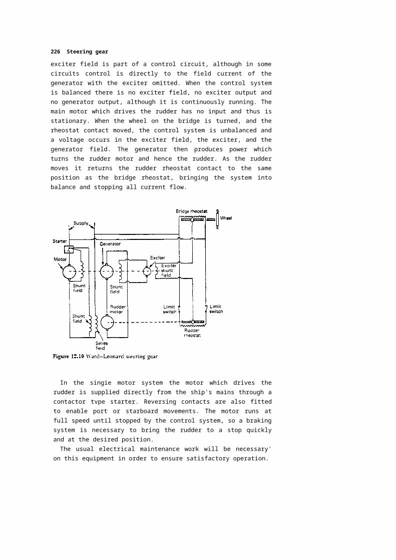
A Ward-Leonard arrangement is shown diagrammatically in Figure 12.10. A continuously running motor-generator set has a directly coupled exciter to provide the field current of the generator. The
226 Steering gear
exciter field is part of a control circuit, although in some circuits control is directly to the field current of the generator with the exciter omitted. When the control system is balanced there is no exciter field, no exciter output and no generator output, although it is continuously running. The main motor which drives the rudder has no input and thus is stationary. When the wheel on the bridge is turned, and the rheostat contact moved, the control system is unbalanced and a voltage occurs in the exciter field, the exciter, and the generator field. The generator then produces power which turns the rudder motor and hence the rudder. As the rudder moves it returns the rudder rheostat contact to the same position as the bridge rheostat, bringing the system into balance and stopping all current flow.
In the singie motor system the motor which drives the rudder is supplied directly from the ship's mains through a contactor tvpe starter. Reversing contacts are also fitted to enable port or starboard movements. The motor runs at full speed until stopped by the control system, so a braking system is necessary to bring the rudder to a stop quickly and at the desired position.
The usual electrical maintenance work will be necessary' on this equipment in order to ensure satisfactory operation.
Twin system steering gears
To meet the automatic changeover within the 45 seconds required for tankers of 10 000 ton gross tonnage and above, a number of designs are available. Two will be described, one for a ram type steering gear and one for a rotary vane type steering gear. In each case two independent systems provide the power source to move the tiller, the failure of one resulting in a changeover to the other. The changeover is automatic and is achieved within 45 seconds.
The ram type steering gear arrangement is shown diagrammatically in Figure 12.11. A simple automatic device monitors the quantity of oil in the circuit. Where a failure occurs in one of the systems it is located and
that drcuit is isolated. The other system provides uninterrupted steering and alarms are sounded and displayed.
Consider pump 1 in operation and pump 2 placed on automatic reserve by the selector switch. If a leak develops in circuit 2 the float chamber oil level will fall and proximity switch A on the monitor will be activated to close the solenoid valve 2 which isolates circuit 2 and bypasses the cylinders in that circuit. An alarm will also be given. If the leak is in circuit 1 however, the float chamber oil level will fall further until proximity switch B is activated. This will cut off the power supply to motor 1 and solenoid valve 1 and connect the supply to motor 2 and solenoid valve 2, thus isolating circuit 1. If pump 2 were running and pump 1 in reserve, a similar changeover would occur. While a two cylinder system has been described this system will operate equally well with four double acting cylinders.
An arrangement based on a rotary vane type steering gear is shown in Figure 12.12. This system involves the use of only one actuator but it is directly fitted to a single tiller and rudderstock and therefore complete duplication of the system does not occur anyway. Self closing lock valves are provided in the two independent hydraulic circuits which operate
rthe actuator. The self closing valves are fitted on the inlet and outlet ports of the actuator and open under oil pressure against the action of a spring. Where an oil pressure loss occurs in one circuit the valves will immediately close under the action of their springs. A low tank level alarm will sound and the other pump can be started. This pump will build up pressure, open the valves on its circuit and the steering gear can immediately operate.
Steering gear testing
Prior to a ship's departure from any port the steering gear should be tested to ensure satisfactory operation. These tests should include:
1. Operation of the main steering gear.2. Operation of the auxiliary steering gear or use of the second pump which acts as the
auxiliary.3. Operation of the remote control (telemotor) system or systems from the main bridge
steering positions.4. Operation of the steering gear using the emergency power supply.5. The rudder angle indicator reading with respect to the actual rudder angle should be
checked.6. The alarms fitted to the remote control system and the steering gear power units should
be checked for correct operation.
During these tests the rudder should be moved through its full travel in both directions and the various equipment items, linkages, etc., visually inspected for damage or wear. The communication system between the bridge and the steering gear compartment should also be operated.
.Chapter 13.Fire fighting and safety
Fire is a constant hazard at sea. It results in more total losses of ships than any other form of casualty. Almost all fires are the result of negligence or carelessness.
Combustion occurs when the gases or vapours given off by a substance are ignited: it is the gas given off that burns, not the substance. The temperature of the substance at which it gives off enough gas to continue burning is known as the 'flash point'.
Fire is the result of a combination of three factors:
1. A substance that will burn.2. An ignition source.3. A supply of oxygen, usually from the air.
These three factors are often considered as the sides of the/irf triangle. Removing any one or more of these sides will break the triangle and result in the fire being put out. The complete absence of one of the three will ensure that a fire never starts.
Fire? are classified according to the types of material which are acting as fuel. These classifications are also used for extinguishers and it is essential to use the correct classification of extinguisher for a fire. to avoid spreading the fire or creating additional hazards. The classifications use the letters A, B, C. D and E.
Class A Fires burning wood. glass fibre, upholsterv and furnishings. Class B Fires burning liquids such as lubricating oil and fuels. Class C Fires burning gas fuels such as liquefied petroleum gas. Class D Fires burning combustible metals such as magnesium and
aluminium. Class E Fires burning any of the above materials together with highvoltage electricity.
Many fire extinguishers will have multiple classifications such as A, B and C.
Fire fighting at sea may be considered in three distinct stages, detection— locating the fire; alarm— informing the rest of the ship; and control—bringing to bear the means of extinguishing the fire.
DetectionThe use of fire detectors is increasing, particularly with the tendency to reduced manning and unmanned machinery spaces. A fire, if detected quickly, can be fought and brought under control with a minimum of damage. The main function of a fire detector is therefore to detect a fire as quickly as possible; it must also be reliable and require a minimum of attention. An important requirement is that it is not set off by any of the normal occurrences in the protected space, that is it must be appropriately sensitive to its surroundings. Three phenomena associated with fire are used to provide alarms: these are smoke, flames and heat.
The smoke detector makes use of two ionisation chambers, one open to the atmosphere and one closed (Figure 13.1). The fine particles or aerosols given off by a fire alter the resistance in the open ionisation chamber, resulting in the operation of a cold cathode gas-filled valve. The alarm sounds on the operation of the valve to give warning of a fire. Smoke detectors are used in machinery spaces, accommodation areasand cargo holds.
Flames, as opposed to smoke, are often the main result of gas and liquid fires and flame detectors are used to protect against such hazards. Flames give off ultra-violet and infra-red radiation and detectors are available to respond to either. An infra-red flame detector is shown in Figure 13.2. Flame detectors are used near to fuel handling equipment in the machinery spaces and also at boiler fronts.
Heat detectors can use any of a number of principles of operation, such as liquid expansion, low melting point material or bimetallic strips. The most usual detector nowadays operates on either a set temperature rise or a rate of temperature rise being exceeded. Thus an increase in temperature occurring quickly could set off the alarm before the set temperature was reached. The relative movement of two coiled bimetallic thermostats, one exposed and one shielded, acts as the detecting element (Figure 13.3). Heat detectors are used in places such as the galley and laundry where other types of detector would give off false alarms.
AlarmAssociated with fire detectors is the electric circuit to ring an alarm bell. This bell will usually sound in the machinery space, if the fire occurs there, and also on the bridge. Fires in other spaces will result in alarm bells sounding on the bridge. Any fire discovered in its early stages will require the finder to give the alarm and or make the decision to deal with it himself if he can. Giving the alarm can take many forms such as
shouting 'Fire', banging on bulkheads or any action necessary to attract attention. It is necessary to give an alarm in order to concentrate resources and effort quickly onto the fire, even if the fire must be left to burn for a short time unchecked.
ControlTwo basically different types of equipment are available on board ship for the control of fires. These are small portable extinguishers and large fixed installations. The small portable extinguishers are for small fires which, by prompt on-the-spot action, can be rapidly extinguished. The fixed installation is used when the fire cannot be fought or restrained by portable equipment or there is perhaps a greater danger if associated areas were to be set on fire. The use of fixed installations may require evacuation of the area containing the fire which, if it is the machinery space, means the loss of effective control of the ship. Various types of both portable and fixed fire fighting equipment are available.
Fire fighting equipment Portable
extinguishers
There are four principal types of portable extinguisher usually found on board ship. These are the soda-acid, foam, dry powder and carbon dioxideextinguishers.
Soda-acid extinguisherThe container of this extinguisher holds a sodium bicarbonate solution. The screw-on cap contains a plunger mechanism covered by a safety guard. Below the plunger is a glass phial containing sulphuric acid (Figure 13.4). When the plunger is struck the glass phial is broken and the acid and sodium bicarbonate mix. The resulting chemical reaction produces carbon dioxide gas which pressurises the space above the liquid forcing k oui through the internal pipe to the nozzle. This extinguisher is used for Class A fires and will be found in accommodation areas.
Foam extinguisher—chemicalThe main container is filled with sodium bicarbonate solution and a long inner polythene container is filled with aluminium sulphate (Figure 13.5(a)). The inner container is sealed by a cap held in place by a plunger. When the plunger is unlocked by turning it, the cap is released.
The extinguisher is then inverted for the two liquids to mix. Carbon dioxide is produced by the reaction which pressurises the container and forces out the foam.
Foam extinguisher—mechanicalThe outer container in this case is filled with water. The central container holds a carbon dioxide charge and a foam solution (Figure 13.5fb)). A plunger mechanism with a safety guard is located above the central container. When the plunger is depressed the carbon dioxide is released and the foam solution and water mix. They are then forced out through a special nozzle which creates the mechanical foam. This extinguisher has an internal pipe and is operated upright.
Foam extinguishers are used on Class B fires and will be located in the vicinity of flammable liquids.
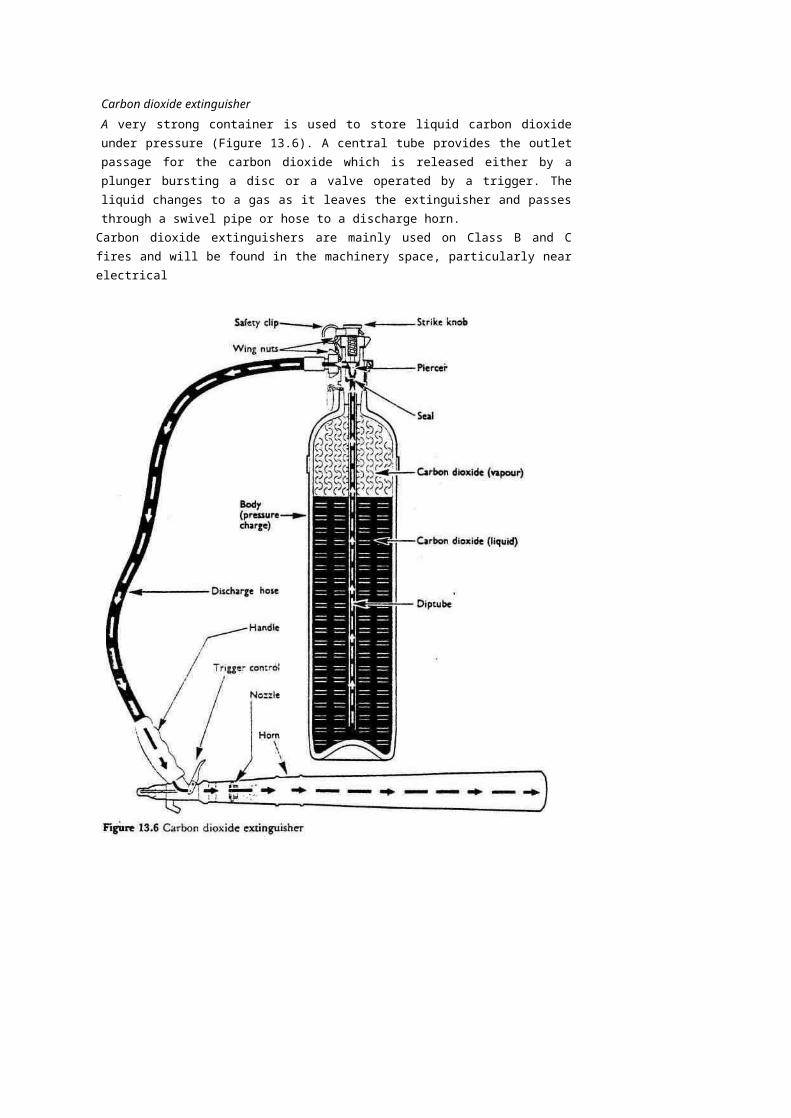
Carbon dioxide extinguisherA very strong container is used to store liquid carbon dioxide under pressure (Figure 13.6). A central tube provides the outlet passage for the carbon dioxide which is released either by a plunger bursting a disc or a valve operated by a trigger. The liquid changes to a gas as it leaves the extinguisher and passes through a swivel pipe or hose to a discharge horn.
Carbon dioxide extinguishers are mainly used on Class B and C fires and will be found in the machinery space, particularly near electrical
equipment. The carbon dioxide extinguisher is not permitted in the accommodation since, in a confined space, it could be lethal.
Dry powder extinguishersThe outer container contains sodium bicarbonate powder. A capsule of carbon dioxide gas is located beneath a plunger mechanism in the central cap (Figure 13.7). On depressing the plunger the carbon dioxide gas forces the powder up a discharge tube and out of the discharge nozzle.
The dry powder extinguisher can be used on all classes of fire but it has no cooling effect. It is usually located near electrical equipment in the machinery space and elsewhere on the ship.
Maintenance and testingAll portable extinguishers are pressure vessels and must therefore be regularly checked.
The soda-acid and foam extinguisher containers are initially tested to 25 bar for five minutes and thereafter at four-yearly intervals to 20 bar.
The carbon dioxide extinguisher is tested to 207 bar initially every 10 years and after two such tests, every five years. The dry powder extinguisher is tested to 35 bar once every four years.
Most extinguishers should be tested by discharge over a period of one to five years, depending on the extinguisher type, e.g. soda-acid and dry powder types 20% discharged per year, foam types 50% discharged per year. Carbon dioxide extinguishers should be weighed every six months to check for leakage.
Where practicable the operating mechanisms of portable extinguishers should be examined every three months.
Any plunger should be checked for free movement, vent holes should be clear and cap threads lightly greased. Most extinguishers with screw-on caps have a number of holes in the threaded region. These are provided to release pressure before the cap is taken off: they should be checked to be clear.
Fixed installationsA variety of different fixed fire fighting installations exist, some of which are specifically designed for certain types of ship. A selection of the more general installations will now be outlined.
Fire main
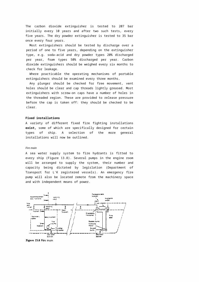
A sea water supply system to fire hydrants is fitted to every ship (Figure 13.8). Several pumps in the engine room will be arranged to supply the system, their number and capacity being dictated by legislation (Department of Transport for L'K registered vessels). An emergency fire pump will also be located remote from the machinery space and with independent means of power.
A system of hydrant outlets, each with an isolating valve, is located around the ship, and hoses with appropriate snap-in connectors are strategically located together with nozzles. These nozzles are usually of the jet/spray type providing either type of discharge as required. All the working areas of the ship are thus covered, and a constant supply of sea water can be brought to bear at any point to fight a fire.
While sea water is best used as a cooling agent in fighting Class A fires it is possible, if all else fails, to use it to fight Class B fires. The jet/spray nozzle would be adjusted to provide a fine water spray which could be played over the fire to cool it without spreading.
An international shore connection is always carried on board ship. This is a standard size flange which is fitted with a coupling suitable for the ship's hoses. The flange is slotted in order to fit any shore-side fire main and enable water to be brought on board a ship lying alongside.
Automatic water spray
The automatic spray or sprinker system provides a network of sprinkler heads throughout the protected spaces. This system may be used in accommodation areas, and in machinery spaces with certain variations in the equipment used and the method of operation.
The accommodation areas are fitted with sprinkler heads which both detect and extinguish fires. The sprinkler head is closed by a quartzoid bulb which contains a liquid that expands considerably on heating (Figure 13.9). When excessively heated the liquid expands, shatters the bulb and water will issue from the sprinkler head. A deflector plate on the sprinkler head causes the water to sprav out over a large area.
The water is supplied initially from a tank pressurised by compressed air (Figure 13.10(a)). Once the tank pressure falls, as a sprinkler issues water, a salt water pump cuts in automatically to maintain the water supply as long as is necessary. The system is initially charged with fresh water to reduce corrosion effects.
The complete installation is divided into several sections, each containing about 150 to 200 sprinklers and having an alarm valve. When one or more sprinklers operate water flows through the section valve and sounds an alarm and also provides a visual display identifying the section containing the fire.
In the machinery space the sprinkler heads are known as 'sprayers' and have no quartzoid bulb. Also the section valves are manually operated to supply water to the spravers (Figure 13.10(b)). The system is pressurised by compressed air with a salt water pump arranged to cut in automatically if the pressure drops. The accommodation and machinery-space systems may be combined bv a valve which is normally kept locked shut.
The svsiem should be regularly checked bv creating fault conditions at the various section control valves bv opening a lest valve, and checking for audible and visual alarms.
Foam systems
Foam spreading systems are designed to suit the particular ship's requirements with regard to quantity of foam, areas 10 be protected, etc. Mechanical foam is the usual substance used, being produced by mixing foam making liquid with large quantities of water. Violent agitation of the mixture in air creates air bubbles in the foam.
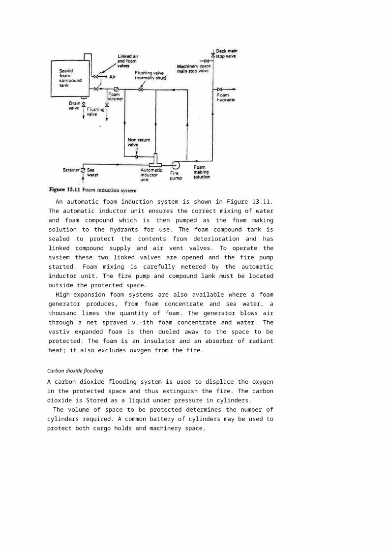
An automatic foam induction system is shown in Figure 13.11. The automatic inductor unit ensures the correct mixing of water and foam compound which is then pumped as the foam making solution to the hydrants for use. The foam compound tank is sealed to protect the contents from deterioration and has linked compound supply and air vent valves. To operate the svsiem these two linked valves are opened and the fire pump started. Foam mixing is carefully metered by the automatic inductor unit. The fire pump and compound lank must be located outside the protected space.
High-expansion foam systems are also available where a foam generator produces, from foam concentrate and sea water, a thousand limes the quantity of foam. The generator blows air through a net spraved v.-ith foam concentrate and water. The vastiv expanded foam is then dueled awav to the space to be protected. The foam is an insulator and an absorber of radiant heat; it also excludes oxvgen from the fire.
Carbon dioxide flooding
A carbon dioxide flooding system is used to displace the oxygen in the protected space and thus extinguish the fire. The carbon dioxide is Stored as a liquid under pressure in cylinders.
The volume of space to be protected determines the number of cylinders required. A common battery of cylinders may be used to protect both cargo holds and machinery space.
The cargo space system is normally arranged for smoke detection, alarm and carbon dioxide flooding (Figure 13.12).
Small air sampling pipes from the individual cargo holds are led into a cabinet on the bridge. Air is drawn from each hold by a small fan and each pipe is identified for its particular hold. If smoke is drawn into the cabinet from one of the holds it will set off an alarm. The smoke is also passed into the wheelhouse where it can be detected by personnel on watch.
The location of the fire can be identified in the cabinet and the hold distribution valve below the cabinet is operated. This valve shuts off the sampling pipe from the cabinet and opens it to the carbon dioxide main leading from the cylinder battery. A chart will indicate the number of cylinders of gas to be released into the space and this is done by a hand operated lever.
The machinery space system is designed to quickly discharge the complete battery of cylinders. Before the gas is released the space must be clear of personnel and sealed against entry or exhausting of air.
The discharge valve is located in a locked cabinet, with the key in a glass case nearby. Opening the cabinet sounds an alarm to warn personnel of the imminent discharge of the gas. The discharge valve is opened and an operating lever pulled.
The operating lever opens two gas bottles which pressurise a gang release cylinder that, in turn, moves an operating cable to open all the bottles in the battery. The carbon dioxide gas then quickly floods the
machinery space, filling it to 30% of its volume in two minutes or less.The air sampling system can be checked when the holds are empty by using a smoking
rag beneath a sampling point. Flow indicators, usually small propellers, are fitted at the outlet points of the smoke detecting pipes as a visual check and an assurance that the pipes are clear. To check for leakage the gas cylinders can be weighed or have their liquid levels measured by a special unit.
Inert gas
Inert gases are those which'do not support combustion and are largely nitrogen and carbon dioxide. Large quantities suitable for fire extinguishing can be obtained by burning fuel in carefully measured amounts or by cleaning the exhaust gases from a boiler.
Inert gas generator
The inert gas generator (Figure 13.13) bums fuel in designed quantities to produce perfect combustion. This provides an exhaust gas which is largely nitrogen and carbon dioxide with a very small oxygen content. The exhaust gases pass to a cooling and washing chamber to remove sulphur and excess carbon. The washed or scrubbed exhaust gas is now inert and passes to a distribution system for fire extinguishing. The complete unit is arranged to be independently operated in order to supply inert gas for as long as the fuel supply lasts.
Funnel gas inerting ^
A system much used on tankers where boiler exhaust gases are cleaned and inerted is shown in Figure 13.14. The exhaust gas is cleaned in a scrubbing tower, dried and filtered before being passed to the deck mains for distribution. The gas will contain less than 5% oxygen and is therefore considered inert. It is distributed along the deck pipes by fans and passes into the various cargo tanks. Seals in the system act as non-return valves to prevent a reverse flow of gas.
The inert gas is used to blanket the oil cargo during discharging operations. Empty tanks are filled with gas and the inert gas is blown out when oil is loaded.
Inert gas-producing units have the advantage of being able to continuously produce inert gas. A bottle storage system, such as carbon dioxide flooding, is a 'one-shot' fire extinguisher which leaves a ship unprotected until further gas supplies can be obtained.
Halon systemHalon 1301 (BTM) and Halon 1211 (BCF) are two halogenated hydrocarbon gases with special fire extinguishing properties. Unlike other extinguishing agents which cool the fire or displace oxygen the Halon gases inhibit the actual flame reaction. As a result of its low vapour pressure when liquefied Halon can be stored in low-pressure containers. Alternatively if a standard carbon dioxide cylinder is used then approximately three times as much gas can be stored. An additional advantage is that the atmosphere in a Halon flooded space is not toxic, although some highly irritant gases are produced in the extinguishing process.
A Halon storage system would be very similar to one using carbon dioxide except that fewer cylinders would be required. The liquefied Halon is usually pressurised in the cylinders with nitrogen in order to increase the speed of discharge. Bulk storage tanks of Halon gas are also used with cylinders of carbon dioxide and compressed air being used to operate the control system and expel the gas.
Fire fighting strategy
Fighting a fire on board ship may amount to a life or death struggle; to enter into such a conflict unprepared and unarmed is to invite failure. The 'armaments' or equipment available have been described. Now comes the matter of being prepared.
A basic strategy should be followed in all fire fighting situations. This
will involve four distinct aspects, which are locating, informing, containing and finally extinguishing a fire.
A fire may be located by detection devices fitted in the various spaces in a ship or simply by smelling or seeing smoke. Alert personnel, whether on watch or not, should always be conscious of the danger of fire and the signs which indicate it. Certain areas are more liable to outbreaks of fire and these should be regularly visited or checked upon.
Once detected the presence of a fire must be made known quickly to as many people as possible. It is essential therefore that the bridge is informed of the location and extent of the fire. A small fire might reasonably be immediately tackled by the finder but attempts should be made whilst fighting the fire to attract attention. Shouting 'Fire', banging on bulkheads, deliberately setting off equipment alarms in the vicinity, all are possible means of attracting attention. Anyone finding a fire must decide whether to fight it immediately or whether to leave it and inform others first. The more people who know of a fire the greater the efforts that can be brought to bear upon it. If in doubt—inform!
Ships are built to contain fires in the space where they begin. Fire resisting bulkheads and decks are positioned at appropriate distances in order to limit the spread of fire, and it remains for fire fighting personnel to ensure that these barriers are secure whilst attempting to fight the fire. All doors and openings should be closed, all ventilation and exhaust fans stopped, and flammable material isolated from the space. It should be remembered that a fire exists in three dimensions and therefore has six sides, so it must be contained on six sides.
A small fire can usually be easily extinguished but it can also quickly become a big fire, so the fire extinguishing must be rapid if it is to be effective. Fire fighting strategy will vary according to the location of the fire. The various areas and their particular problems will .now be examined.
AccommodationThe accommodation areas will be made up almost exclusively of Class A material requiring the use of water or soda-acid type extinguishers. Electrical circuits however should be isolated before directing quantities of water into an accommodation area. All ventilation and exhaust fans must be stopped and fire flaps closed. If hoses are employed a water sprav should be used in order to achieve the maximum cooling effect. The accommodation will no doubt fill with smoke and therefore breathing apparatus should be available.
The galley area presents a somewhat different fire hazard. Here Class B materials, such as cooking oil, fat or grease, will be present requiring the use of foam, dry powder or carbon dioxide extinguishers. A fire
blanket quickly spread over burning cooking utensils could extinguish a potentially dangerous fire.
Machinery spacesMachinery space fires will involve mainly Class B material requiring the use of foam type extinguishers. Only the smallest of fires should be tackled with hand extinguishers. The alarm should be quickly given and the bridge informed. The ventilation fans should be stopped and fire flaps closed. Any oil tanks close to the fire should be closed off and kept cool by hosing with water. Foam-making equipment should be used on the fire and foam spread over the tank tops and bilges. Water spray can also be used to cool the surroundings of the fire, but a water jet should not be used in the machinery space since it will move any burning oil around and subsequently spread the fire. Only if the situation becomes hopeless should the space be evacuated and gas flooding used. The machinery space contains most of the fire fighting equipment as well as the propulsion machinery. If it is vacated then control of the situation is lost to a 'one-shot' attempt at gas flooding.
If evacuation is decided upon all personnel must be made aware of the decision. The space must then be completely sealed against the entry or exit of air and all oil supplies isolated at the tank valves. When all these matters have been attended to, the flooding gas can be admitted and, if the surrounding bulkheads hold to contain the fire, it will quickly go out. Cooling of the boundary bulkheads should continue from outside the space whilst flooding is taking place.
When the extinguished fire has been left long enough to cool down the space can be re-entered. This should be done from the tunnel, if there is one, or the lowest point remote from the seat of the fire. Engineers wearing breathing apparatus may now enter, taking water spray hoses with them to cool down any hot surfaces. Cooling and smoke dispersal are the first priorities to provide an atmosphere in which others can operate and gradually bring the machinery back into service. Where a machinery space fire involves electrical equipment then onlv dry powder or carbon dioxide extinguishers can be used until the equipment is isolated.
Cargo spacesWhere a fire occurs in a cargo hold with a smoke detection and carbon dioxide flooding system fitted, the procedure is straightforward and has already been described. It is essential to ensure before flooding that all air entry and exit points are closed by fire dampers and all fans are stopped.
Oil tankers with their cargo tanks full or empty present a potentially serious fire hazard. A fire occurring in a cargo tank will doubtless lead to an explosion or an explosion will lead to fire. The rapid use of foam making equipment, the cooling of surrounding areas and the isolation of the fire should immediately take place.
The prevention of fire and explosion conditions is the main prerequisite with oil tankers. With reference to hydrocarbon vapours, such as those present in oil tanks, the diagram shown in Figure 13.15 should be considered. The relative proportions of hydrocarbon vapour and oxygen necessary for a fire or explosion are shown. By keeping the tank atmosphere outside of the flammable limits, no fire or explosion can occur. It is usual practice to inert the tank atmosphere by displacing the oxygen with an inert gas and thus effectively prevent a fire or explosion. The inert gas producing systems have already been described.
Training and awarenessWhere is the nearest fire extinguisher? What type is it? How is it operated? At any position in the ship these questions should be asked
and answered. Knowing how to operate any extinguisher just by looking at it will indicate some degree of training and an awareness of the fire defences.
Fire drills are often referred to as 'Board of Trade Sports', but they merit a more sober attitude than they receive. Practices are useful and should be seriously undertaken. Equipment should be tried and tested to ensure that it works and is ready when needed. Regular maintenance should take place on extinguishers, fire pumps, hydrants, hoses, etc. All engineers should be familiar with recharging and overhauling extinguishers and those in charge should make sure it is regularly done. The statutory surveys do much to ensure that equipment is ready for use but the one year period between leaves a lot of time for neglect.
Breathing apparatusMany fire fighting situations may require the use of some form of breathing apparatus. The use of such equipment will ensure a supply of oxygen to the wearer so that he can perform his particular tasks in safety. Two basic types are in use—-the smoke helmet and the self-contained unit using air cylinders.
The smoke helmet arrangement uses a helmet which covers the head and is connected to an air hose. A hand operated pump or bellows supplies the air. A system of signals between user and supplier must be arranged to ensure safe, correct operation.
The self-contained unit consists of one or two cylinders of compressed air kept in a harness which is carried on the back (Figure 13.16). The high pressure air is fed through a reducing valve and then to a demand valve. The demand valve is fitted into a face mask and supplies air to meet the breathing requirements of the wearer. A non-return valve permits breathing out to atmosphere. A warning whistle sounds when the air pressure falls to a low value. A standard cylinder will allow for about 20 to 30 minutes' operation.
Safe working practices
Accidents are usually the result of carelessness, mistakes, lack of thought or care, and often result in injury. Consideration will now be given to avoiding accidents, largely bv the adoption of safe working practices.
Working clothes should be chosen with the job and its hazards in mind. Thev should fit fairlv closely with no loose f.aps. straps or ragged pockets. Clothing should cover as much of the bodv as possible and a stout pair of shoes should be worn. Neck chains, finger rings and wristwatches should not be worn, particularly in the vicinity of rotating machinery. Where particular hazards are present appropriate protection. such as goggles or ear muffs, should be worn.
When overhauling machinery or equipmen: it must be effecr.veiy isolated from all sources of power. This rnav involve unplugging from an electrical circuit, the removal of fuses or the securing open of circuit breakers. Suction and discharge valves of pumps should be securely closed and the pump casing relieved of pressure. Special care should be taken with steam-operated or steam-using equipment to ensure no pressure build-up can occur.
When lifting equipment during overhaul, screw-in eye bolts should be used where possible. These should be fully entered up 10 the collar and the threads on the eveboli and in the equipment should be in good condition. Anv lifting wires should be in good condition without broken strands or sharp edges.
Before anv work is done on the main engine, the turning gear should be engaged and a warning posted at the control position. Lubricating oil in the working area should be cleaned up and where necessary suitable staging erected. The turning gear should be made inoperative if not required during the overhaul. Where it is used, care must be taken to ensure all personnel are clear before it is used.
Where overhead work is necessary suitable staging should be provided and adequately lashed down. Staging planks should be examined before use and where suspect discarded. W^here ladders are used for access they must be secured at either end. Personnel working on staging should take care wdth tools and store them in a container.
Boiler blow-backs can cause serious injurv and yet with care can usually be avoided. The furnace floor should be free of oil and burners regularly checked to ensure that they do not drip, particularly when not in use. The manufacturer's instructions should be followed with regard to lighting up procedures. Generally this will involve blowing through the furnace (purging) with air prior to lighting up. The fuel oil must be at the correct temperature and lit with a torch. If ignition does not immediately occur the oil should be turned off and purging repeated before a second attempt is made. The burner should be withdrawn and examined before it is lit.
Entry into an enclosed space should onlv take place under certain specified conditions. An enclosed space, such as a duct keel, a double bottom tank, a cofferdam, boiler, etc. cannot be assumed to contain oxvgen. Anyone requiring 10 enter such a space should only do so with the permission of a responsible officer. The space should be well ventilated before entry takes place and breathing apparatus taken along:it should be used if any discomfort or drowsiness is fell. Another person should remain at the entrance to summon assistance if necessary, and there should be a means of communication arranged between the person within the space and the attendant. Lifelines and harness should be available at the entrance to the space. The attendant should first raise the alcirm v.'here the occup^n: appear? ir; danger but should no'i enter the space unless equipped with breathing apparatus.
Training in the use of safetv equipment and the conduct of rescues is essential for all personnel involved.
.Chapter 14.Electrical equipment
The complete electrical plant on board ship is made up of power generation equipment, a distribution system and the many power utilising devices. Electricity is used for the motor drive of many auxiliaries and also for deck machinery, lighting, ventilation and air conditioning equipment. A constant supply of electricity is essential for safe ship and machinery operation, and therefore standby or additional capacity is necessary together with emergency supply equipment. Emergency equipment may take the form of an automatically starting emergency alternator or storage batteries may be used.
The complete range of electrical equipment will include generators, switch gear for control and distribution, motors and their associated starting equipment and emergency supply arrangements.
Alternating or direct currentAlternating current has now all but replaced direct current as the standard supply for all marine installations. The use of alternating current has a number of important advantages: for example, reduced first cost. less weight, less space required and a reduction in maintenance requirements. Direct current does, however, offer advantages in motor control using, for example, the Ward-Leonard system which provides a wide rar.a'e of speed.
Machine rating
Motors and generators, both d.c. and a.c.. are rated as Continuous Maximum Rated (CMR) machines. This means they can accept a considerable momentary overload and perhaps even a moderate overload for a longer duration.
Temperature affects the performance of all electrical equipment and also the useful life of the insulation and thus the equipment itself. The total temperature of an operating machine is a result of the ambient air
temperature and the heating effect of current in the windings. :.Temperature rise is measured above this total temperature. Adequate -ventilation of electrical equipment is therefore essential. Classification /
Societies have set requirements for the various classes of insulation. The ,-usual classes for marine installations are E, B and F where particularinsulation materials are specified and increasing temperature rises
allowed in the order stated.
Enclosures
^ Depending upon the location, a motor or generator will have one of a number of possible tvpes of enclosure. "Drip-proof is most common and
^ provides protection from falling liquids or liquids being drawn in by ventilating air. A -watertight enclosure' provides protection for immersion under a low head of water for up to one hour. 'Weatherproof, 'hose proof and -deck watertight' provide immersion protection for only one minute. "Totally enclosed' can also be used or an arrangement providing dueled ventilation from outside the machinery space. A "flameproof enclosure is capable of withstanding an explosion of some particular flammable gas that may occur within it. It must also stop the transfer of flame, i.e. contain any fire or explosion.
Direct current generators
A current iy produced when a single coil of wire is rotated in a magnetic field. When the current is collected using a ring which is split into two halves (2. commutator), a direct or single direction current is produced. The current produced may be increased by the use of many turns of wire and additional magnetic fields.
V\ ith manv coils connected to the commutator, sparking will occur as the current collecting brushes move across the insulated segments. Commu:ating poles or inierpoies are used to reduce this sparking. They are in fact electromagnets having a polarkv the same as the main pole which follows in the direction of" rotation.
The magnetic field between the poles is produced by what are known as 'field coils'. These coils are excited or energised bv the current produced in the machine. The soft iron core of the field coils retains some magnetism which enables a preliminary current generation to build up eventually to the full machine output. The field windings can be connected to the output current in a number of ways—shunt, series or compound. The compound wound arrangement is usual since it provides the best voltage characteristics.
254 Electrical equipment
The compound wound generator has two sets of field coils (Figure 14.1 (a)). The shunt coil has many turns of fine wire and the series coil has a few turns of heavy wire. The shunt field produces full voltage on no-load which falls off as the load current increases. The series field creates an increase in voltage as the load increases. Properly combined or compounded the result is a fairly constant voltage over a range of load (Figure 14.1(b)).
Direct current distributionThe generated supply is provided to conductors known as 'bus-bars' which are located behind the main switchboard. The supply then passes through circuit breakers to auxiliaries directly or to section or distribution boards. A circuit breaker is an isolating switch. A section board is a grouping of electrical services fed from the main board. A
distribution board feeds minor supplies such as lighting and may itself be fed from the main board or a section board. The distribution system is shown in Figure 14.2.
A two wire system is usual to provide a supply and return to each item of equipment. An earth lead would be the only electrical connection between any item of equipment and the ship's structure. With compound wound generators a third bus-bar would be introduced as the equalising connection between machines.
A fuse is a type of switch which isolates a circuit if an excessive current flows. To reconnect the circuit, after discovering the cause of the overload, the fuse must be rewired or replaced. The fuse is in effect a weak link in the circuit designed to break and protect equipment from damaging high currents. A semi-enclosed or rewirable fuse will have provision for a wire to be replaced after it has burnt out. The correct rating of fuse wire should be replaced within the holder to reinstate the circuit. A cartridge fuse has the wire enclosed within a ceramic body and it is not rewirable. A 'blown' cartridge fuse must be replaced by a new one. The cartridge fuse is to be preferred since the fusing current value is more reliable than for a rewirable tvpe.
A circuit breaker is an isolating switch which also functions as a fuse. It has two designed ratings: one of the normal safe working current, the other the overload current. The breaker is closed against the action of a spring to make the circuit and supply the section board or auxiliary. A trip mechanism opens the breaker, a fast opening being ensured by the spring. When desired the breaker is tripped or opened manually. It will also open if the overload current rating is exceeded for a oeriod of time.
A delay mechanism prevents the breaker opening for short-period overload currents. The circuit breaker opens or closes both supply and return leads in the circuit. Where a circuit breaker feeds the generator supply to the bus-bars a third 'make-or-break' arm will be provided for the equaliser connection.
Preferential tripping is a means of retaining essential electrical supplies. In the event that a generator cannot supply all the load then non-essential loads are disconnected by preferential trips. The intention is to reduce the generator load while ensuring essential equipment such as steering gear, navigation lights, etc., retains its electrical supply.
Various circuit faults can occur as a result of either a break in the conductor (cable) or a break in the insulation. An open-circuit fault results from a break in the conductor and no current flow will take place. A short-circuit fault is due to two breaks in the insulation on, for example, adjacent conductors. The two conductors are connected and a large current flow takes place. An earth fault occurs when a break in the insulation permits the conductor to touch an earthed metal enclosure (or the hull).
Earth faults are usually detected by the use of earth indicating lamps. Two lamps are used, each rated for the full system voltage, but connected in series across the system with the mid point earthed (Figure 14.3). If the system is correctly insulated then both lamps will glow at
half brilliance. The lamps are placed close together to enable a comparison to be made. A direct earth in one pole will short circuit its lamp causing the other to shine brightly. A slight insulation breakdown would produce a difference in bulb brightness between the two. Where an earth fault is detected the circuit breakers for each separate circuit must be opened in turn until the fault location is discovered. The particular section or distribution box would then have to have its circuits investigated one by one to locale the fault and enable its correction.
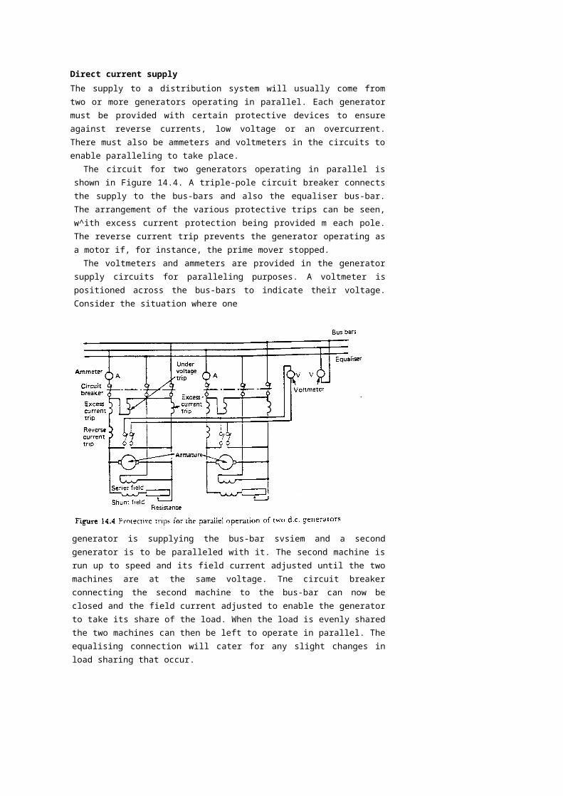
Direct current supplyThe supply to a distribution system will usually come from two or more generators operating in parallel. Each generator must be provided with certain protective devices to ensure against reverse currents, low voltage or an overcurrent. There must also be ammeters and voltmeters in the circuits to enable paralleling to take place.
The circuit for two generators operating in parallel is shown in Figure 14.4. A triple-pole circuit breaker connects the supply to the bus-bars and also the equaliser bus-bar. The arrangement of the various protective trips can be seen, w^ith excess current protection being provided m each pole. The reverse current trip prevents the generator operating as a motor if, for instance, the prime mover stopped.
The voltmeters and ammeters are provided in the generator supply circuits for paralleling purposes. A voltmeter is positioned across the bus-bars to indicate their voltage. Consider the situation where one
generator is supplying the bus-bar svsiem and a second generator is to be paralleled with it. The second machine is run up to speed and its field current adjusted until the two machines are at the same voltage. Tne circuit breaker connecting the second machine to the bus-bar can now be closed and the field current adjusted to enable the generator to take its share of the load. When the load is evenly shared the two machines can then be left to operate in parallel. The equalising connection will cater for any slight changes in load sharing that occur.
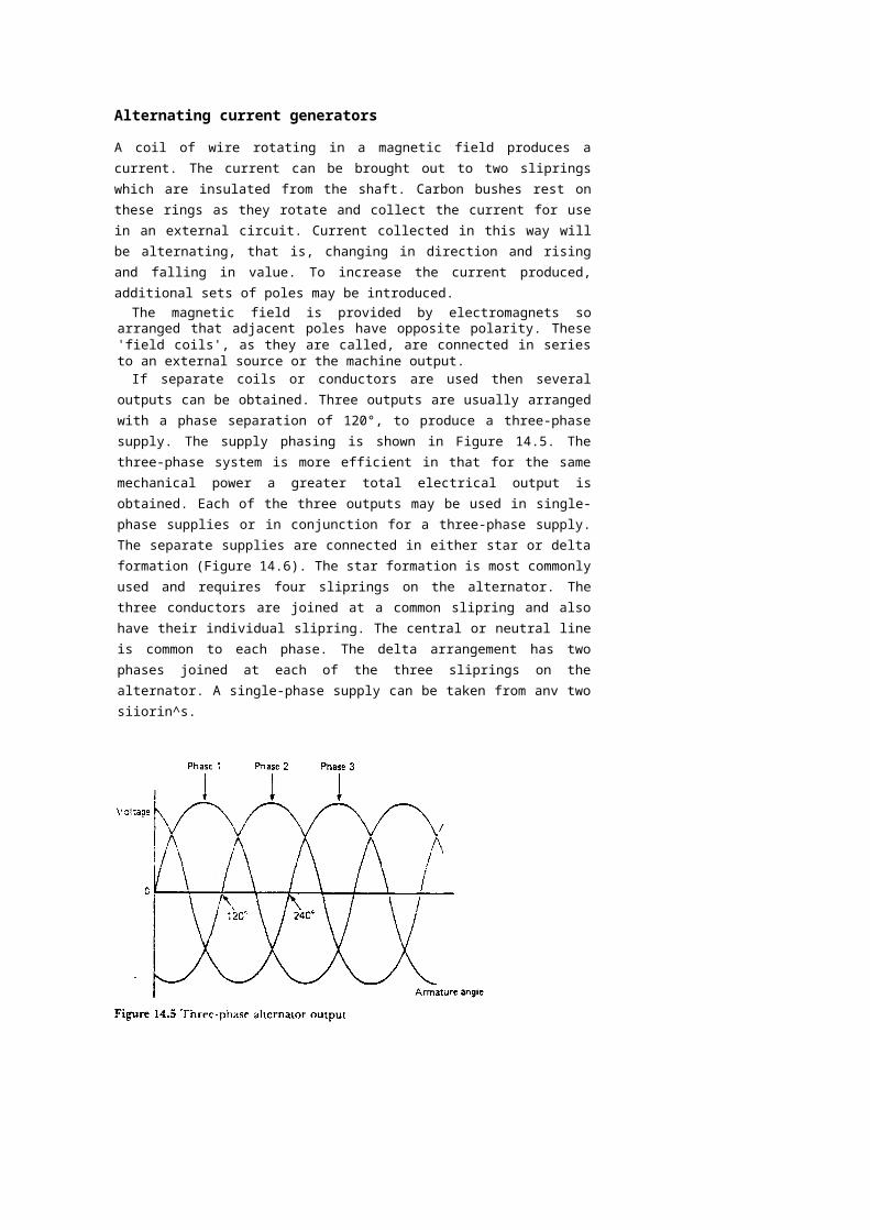
Alternating current generators
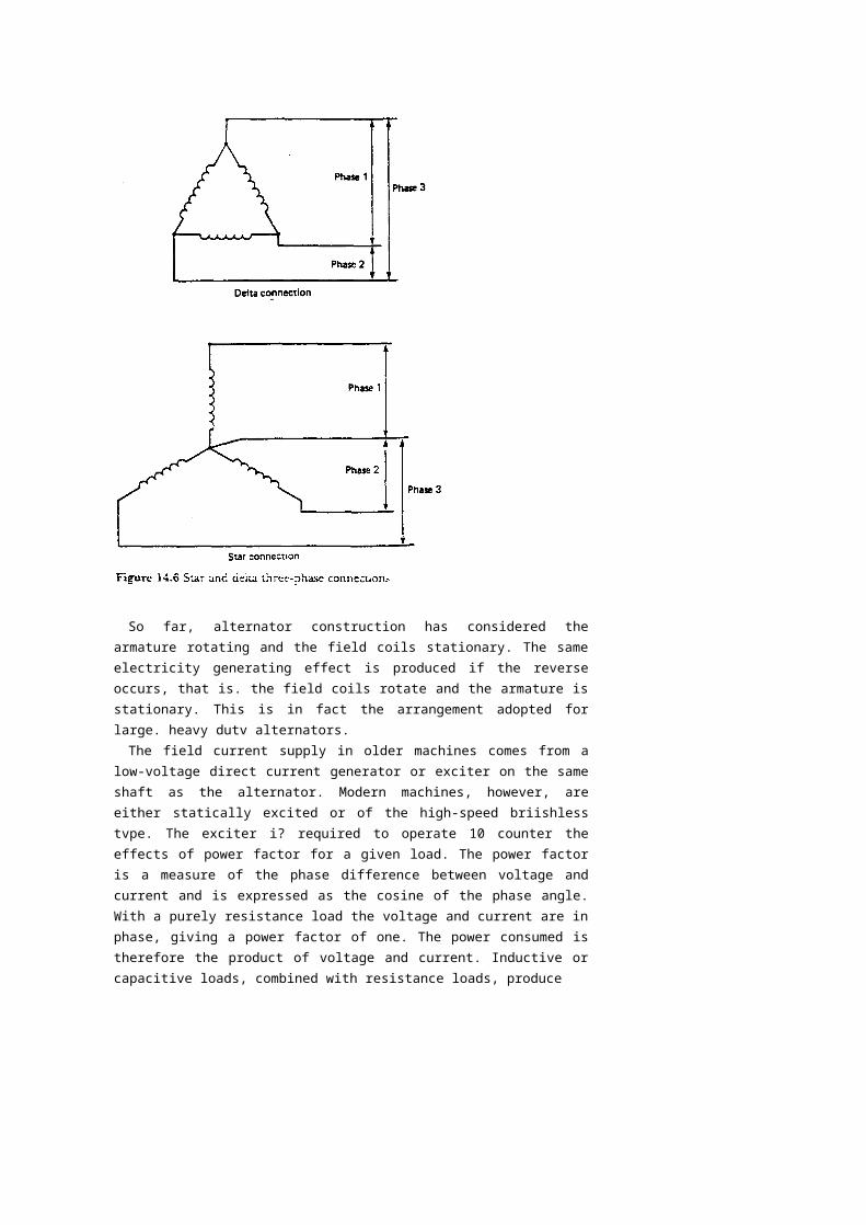
A coil of wire rotating in a magnetic field produces a current. The current can be brought out to two sliprings which are insulated from the shaft. Carbon bushes rest on these rings as they rotate and collect the current for use in an external circuit. Current collected in this way will be alternating, that is, changing in direction and rising and falling in value. To increase the current produced, additional sets of poles may be introduced.
The magnetic field is provided by electromagnets so arranged that adjacent poles have opposite polarity. These 'field coils', as they are called, are connected in series to an external source or the machine output.
If separate coils or conductors are used then several outputs can be obtained. Three outputs are usually arranged with a phase separation of 120°, to produce a three-phase supply. The supply phasing is shown in Figure 14.5. The three-phase system is more efficient in that for the same mechanical power a greater total electrical output is obtained. Each of the three outputs may be used in single-phase supplies or in conjunction for a three-phase supply. The separate supplies are connected in either star or delta formation (Figure 14.6). The star formation is most commonly used and requires four sliprings on the alternator. The three conductors are joined at a common slipring and also have their individual slipring. The central or neutral line is common to each phase. The delta arrangement has two phases joined at each of the three sliprings on the alternator. A single-phase supply can be taken from anv two siiorin^s.
So far, alternator construction has considered the armature rotating and the field coils stationary. The same electricity generating effect is produced if the reverse occurs, that is. the field coils rotate and the armature is stationary. This is in fact the arrangement adopted for large. heavy dutv alternators.
The field current supply in older machines comes from a low-voltage direct current generator or exciter on the same shaft as the alternator. Modern machines, however, are either statically excited or of the high-speed briishless tvpe. The exciter i? required to operate 10 counter the effects of power factor for a given load. The power factor is a measure of the phase difference between voltage and current and is expressed as the cosine of the phase angle. With a purely resistance load the voltage and current are in phase, giving a power factor of one. The power consumed is therefore the product of voltage and current. Inductive or capacitive loads, combined with resistance loads, produce
lagging or leading power factors which have a value less than one. The power consumed is the product of current, voltage and power factor. The alternating current generator supplying a load has a voltage drop resulting from the load. When the load has a lagging power factor this voltage drop is considerable. Therefore the exciter, in maintaining the alternator voltage, must vary with the load current and also the power factor. The speed change of the prime mover must also be taken into account.
Hand control of excitation is difficult so use is made of an automatic voltage regulator (AVR). The AVR consists basically of a circuit fed from the alternator output voltage which detects small changes in voltage and feeds a signal to an amplifier which changes the excitation to correct the voltage. Stabilising features are also incorporated in the circuits to avoid 'hunting' (constant voltage fluctuations) or overcorrect-ing. Various designs of AVR are in use which can be broadly divided into classes such as carbon pile types, magnetic amplifiers, electronic types, etc.
The statically excited alternator has a static excitation system instead of a d.c. exciter. This type of alternator will more readily accept the sudden loading by direct on-line starting of large squirrel cage motors. The static excitation system uses transformers and rectifiers to provide series and shunt components for the alternator field, that is, it is compounded. Brushes and siiprings are used to transfer the current to the field coils which are mounted on the roior. The terminal voltage from the alternator thus gives the no-load voltage and the load current
provides the extra excitation to give a steady voltage under any load condition. The careful matching of components provides a system which functions as a self regulator of voltage. Certain practical electrical problems and the compensation necessary for speed variation require that a voltage regulator is also built into the system.
The brushless high speed alternator was also developed to eliminate d.c. exciters with their associated commutators and brushgear. The alternator and exciter rotors are on a common shaft, which also carries the rectifiers. The exciter output is fed to the rectifiers and then through conductors in the hollow shaft to the alternator field coils. An automatic voltage regulator is used with this type of alternator.
The construction of an alternator can be seen in Figure 14.7. The rotor houses the poles which provide the field current, and these are . usually of the salient or projecting-pole type. Slip rings and a fan are also mounted on the rotor shaft, which is driven by the auxiliary engine. The stator core surrounds the rotor and supports the three separate phase windings. Heat is produced in the various windings and must be removed by cooling. The shaft fan drives air over a water-cooled heat exchanger. Electric heaters are used to prevent condensation on the windings when the alternator is not in use.
In addition to auxiliary-engine-driven alternators a ship may have a shaft-driven alternator. In this arrangement a drive is taken from the main engine or the propeller shaft and used to rotate the alternator. The various operating conditions of the engine will inevitably result in variations of the alternator driving speed. A hydraulic pump and gearbox arrangement may be used to provide a constant-speed drive, or the alternator output may be fed to a static frequency converter. In the static frequency converter the a.c. output is first rectified into a variable d.c. voltage and then inverted back into a three-phase a.c. voltage. A feedback system in the oscillator inverter produces a constant-output a.c. voltage and frequency.
Distribution svstemAn a.c. distribution system is provided from the main switchboard which is itself supplied bv the alternators (Figure 14.8). The voltage at the switchboard is usually 440 volts, but on some large installations it may be as high as 3300 volts. Power is supplied through circuit breakers to larger auxiliaries at the high voltage. Smaller equipment may be supplied via fuses or miniature circuit breakers. Lower voltage supplies used, for instance, for lighting at 220 volts, are supplied by step down transformers in the distribution network.The distribution system will be three-wire with insulated or earthed neutral. The insulated neutral has largely been favoured, but earthed
262 Electrical equipment
neutral systems have occasionally been installed. The insulated neutral system can suffer from surges of high voltage as a result of switching or system faults which could damage machinery. Use of the earthed system could result in the loss of an essential service such as the steering gear as a result of an earth fault. An earth fault on the insulated system would not, however, break the supply and would be detected in the earth lamp display. Insulated systems have therefore been given preference since earth faults are a common occurrence on ships and a loss of supply in such situations cannot be accepted.
In the distribution svsiem there wili be circuit breakers and fuses, as mentioned previously for d.c. distribution systems. Equiumen; for a.c. systems is smaller and lighter because of the higher voltage and therefore lower currents. Miniature circuit breakers are used for currents up to about 100 A and act as a fuse and a circuit breaker. The device will open on overload and also in the event of a short circuit. L'niike a fuse, the circuit can be quickly remade bv simply closing the switch. A large version of this device is known as the 'moulded-case circuit breaker' and can handle currents in excess of 1000 A. Preferential tripping and earth fault indication will also be a part of the a.c. distribution system. These two items have been mentioned previously for d.c. distribution svstems.
Alternating current supply
Three-phase alternators arranged for parallel operation require a considerable amount of instrumentation. This will include ammeters, wattmeter, voltmeter, frequency meter and a synchronising device. Most of these instruments will use transformers to reduce the actual values taken to the instrument. This also enables switching, for instance, between phases or an incoming machine and the bus-bars, so that one instrument can display one of a number of values. The wattmeter measures the power being used in a circuit, which, because of the power factor aspect of alternating current load, will be less than the product of the volts and amps. Reverse power protection is provided to alternators since reverse current protection cannot be used. Alternatively various trips may be provided in the event of prime mover failure to ensure that the alternator does not act as a motor.
The operation of paralleling two alternators requires the voltages to be equal and also in phase. The alternating current output of any machine is always changing, so for two machines to operate together their voltages must be changing at the same rate or frequency and be reaching their maximum (or anv other value) together. They are then said to be 'in phase'. Use is nowadays made of a synchroscope when paralleling two a.c. machines. The synchroscope has two windings which are connected one to each side of the paralleling switch. A pointer is free to rotate and is moved bv the magnetic effect of the two windings. When the two voltage supplies are in phase the pointer is stationary in the 12 o'clock position. If the pointer is rotating then a frequency difference exists arid the diai is marked for cloci-.wise rotation FAST ar'd anti-clockwise rotation SLOW. the reference being to the incoming machine frequency.
To parallel an incoming machine to a running machine therefore it is necessarv to ensure firsth that both voltages are equal. Voltmeters are provided for this purpose. Secondly the frequencies must be brought into phase. In practice the synchroscope usuallv moves slowly in the FAST direction and the paralleling switch is closed as the pointer reaches the 11 o'clock position. This results in the incoming machine immediately accepting a small amount of load.
A set of three lamps may also be provided to enable synchronising. The sequence method of lamp connection has a key lamp connected across one phase with the two other lamps cross connected over the other two phases. If the frequencies of the machines are different the lamps will brighten and darken in rotation, depending upon the incoming frequency being FAST or SLOW. The correct moment for synchronising is when the key lamp is dark and the other two are equally bright.
Direct current motors
When a current is supplied to a single coil of wire in a magnetic field a force is created which rotates the coil. This is a similar situation to the generation of current by a coil moving in a magnetic field. In fact generators and motors are almost interchangeable, depending upon which two of magnetic field, current and motion are provided. Additional coils of wire and more magnetic fields produce a more efficient motor. Interpoles are fitted to reduce sparking but now have opposite polarity to the next main pole in the direction of rotation. When rotating the armature acts as a generator and produces current in the reverse direction to the supply. This is known as back e.m.f. (electromotive force) and causes a voltage drop across the motor. This back e.m.f. controls the power used by the motor but is not present as the motor is started. As a result, to avoid high starting currents special control circuits or starters are used.
The behaviour of the d.c. motor on load is influenced by the voltage drop across the armature, the magnetic field produced between the poles and the load or torque on the motor. Some of these factors are interdependent. For example, the voltage drop across the armature depends upon the back e.m.f. which depends upon the speed of the motor and the strength of the magnetic field. Shunt, series and compound windings are used to obtain different motor characteristics by varying the above factors.
The shunt wound motor has field windings connected in parallel with the armature windings (Figure 14.9). Thus when the motor is operating with a fixed load at constant speed all other factors are constant. An increase in load will cause a drop in speed and therefore a reduction in back e.m.f. A greater current will then flow in the armature windings and the motor power consumption will rise: the magnetic field will be unaffected since it is connected in parallel. Speed reduction is. in
practice, very small, which makes the shunt motor an ideal choice forconstant-speed variable-load duties.
The series motor has field windings connected in series with the armature windings (Figure 14.10). With this arrangement an increase in load will cause a reduction in speed and a fall in back e.m.f. The increased load current will, however, now increase the magnetic field and therefore the back e.m.f. The motor will finally stabilise at some reduced value of speed. The series motor speed therefore changes considerably with load.
Control of d.c. motors is quite straightforward. The shunt wound motor has a variable resistance in the field circuit, as shown in Figure 14.9. This permits variation of the current in the field coils and also the back e.m.f, giving a range of constant speeds. To reverse the motor the field current supply is reversed, as shown in Figure 14.9.
One method of speed control for a series wound motor has a variable resistance in parallel with the field coils. Reverse operation is again achieved by reversing the field current supply as shown in Figure 14.10.
In operation the shunt wound motor runs at constant speed regardless of load. The series motor runs at a speed determined by the load, the greater the load the slower the speed. Compounding—the use of shunt and series field windings—provides a combination of these characteristics. Starting torque is also important. For a series wound motor the starting torque is high and it reduces as the load increases. This makes the series motor useful for winch and crane applications. It should be noted that a series motor if started on no-load has an infinite speed. Some small amount of compounding is usual to avoid this dangerous occurrence. The shunt wound motor is used where constant speed is required regardless of load: for instance, with fans or pumps.
The starting of a d.c. motor requires a circuit arrangement to limit armature current. This is achieved by the use of a starter (Figure 14.11). A number of resistances are provided in the armature and progressively removed as the motor speeds up and back e.m.f. is developed. An arm, as part of ihe armature circuit, moves over resistance contacts such that a number of resistances are first put into the armature circuit and then
progressively removed. The arm must be moved slowly to enable the motor speed and thus the back e.m.f. to build up. At the final contact no resistance is in the armature circuit. A 'hold on' or 'no volts' coil holds the starter arm in place while there is current in the armature circuit. If a loss of supply occurs the arm will be released and returned to the 'off position bv a spring. The motor must then be started again in the normal way. An overload trip is also provided which prevents excess current bv shoning our the 'hold on' coil and releasing the starter arm. The overload coil has a soft iron core which, when magnetised sufficiently by an excess current, attracts the trip bar which shorts out the hold on coil. This tvpe of starter is known as a 'face plate'; other types make use of contacts without the starting handle but introduce resistance into the armature circuit in much the same wav.
Alternating current motors
Supplying alternating current to a coil which is free to rotate in a magnetic field will not produce a motor effect since the current is constantly changing direction. Use is therefore made in an induction or squirrel cage motor of a rotating magnetic field produced by three separately phased windings in the stator. The rotor has a series of copper conductors along its axis which are joined by rings at the ends to form a cage. When the motor is started the rotating magnetic field induces an e.m.f in the cage and thus a current flow. The
current-carrying conductor in a magnetic field produces the motor effect which turns the rotor. The motor speed builds up to a value just less than the speed of rotation of the magnetic field.
The motor speed depends upon the e.m.f. induced in the rotor and this depends upon the difference in speed between the conductors and the magnetic field. If the load is increased the rotor slows down slightly, causing an increase in induced e.m.f. and thus a greater torque to deal with the increased load. The motor is almost constant speed over all values of load. It will start against about two times full load torque but draws a starting current of about six times the normal full load current. The starting current can be reduced by having a double cage arrangement on the rotor. Two separated cages are provided, one below the other in the rotor. When starting, the outer high-resistance cage carries almost all the rotor current. As the motor accelerates the low-resistance inner winding takes more and more of the current until it carries the majority.
A number of different fixed speeds are possible by pole changing. The speed of an induction motor is proportional to frequency divided by the numbers of pairs of poles. If therefore a switch is provided which can alter the numbers of pairs of poles, then various fixed speeds are possible. The number of poles affects the starting characteristics such that the more poles the less the starting torque to full load torque ratio.
Only the induction tvpe of a.c. motor has been described, since it is almost exclusively used in maritime work. Synchronous motors are another type which have been used for electrical propulsion svstems but not auxiliary drives.
A number of different arrangements can be used for sprung an induction motor. These include direct on-line, star delta, auto transformer and stator resistance. Direct on-line starling is usual where the distribution system can accept the starting current. Where a slow moving high inertia load is involved the starling time must be considered because of the healing effect of the starting current. The star delta starter connects the staior windings first in star and v.-hen running changes over 10 delta. The star connection results in about half of the line voltage being applied to each phase with therefore a reduction in starting current. The starting torque is also reduced to about one-third of its direct on line value. A rapid change-over to delta is required at about 75% of full load speed when the motor will draw about three-and-a-half times its full load current. The auto transformer starter is used only for large motors. It uses tappings from a transformer to provide, for example, 40%, 60% and 75% of normal voltage (Figure 14.12). The motor is started on one of the tappings and then quickly switched to full voltage at about 75% full speed. The tapping chosen will depend upon the starting torque required with a 60% tapping giving
about 70% of full load torque. A smaller percentage tapping will give a smaller starting torque and vice-versa. The staler resistance starter has a resistance in the stator circuit when the motor is started. An adjustable timing device operates to short circuit this resistance when the motor has reached a particular speed.
Modern electronic techniques enable a.c. induction motors to be used in speed-control systems. The ship's supply, which may not be as stable in voltage or frequency as that ashore, is first rectified to provide a d.c. supply. This is then used as the power supply of an oscillator using high-power electronic devices. These may be thyristors (for powers up to 1.5 MW or more) or transistors (for powers up to a few tens of kilowatts). The high-power oscillator output is controlled in frequency and voltage by a feedback svsiem. The motor speed is varied by changing the oscillator output frequency. The motor current necessary to obtain the desired torque (at small angles of slip) is normally obtained bv maintaining the voltage almost proportional to frequency.
Certain protective devices are fitted in the motor circuit to protect against faults such as single phasing, overload or undervokage. Single phasing occurs when one phase in a three-phase circuit becomes open circuited. The result is excessive currents in all the windings with. in the case of a delta connected stator running at full load. one winding taking three times its normai load current. A machine which is running when single phasing occurs will continue to run but with an unbalanced distribution of current. An overload protection device may not trip if the motor is running at less than full load. One method of single phasing protection utilises a temperature-sensitive device which isolates the machine from the supply at some particular winding temperature. Overload protection devices are also fitted and may be separate or combined with the single phase protection device. They must have a time delay fitted so that operation does not occur during the high
starting current period. An undervokage or 'no volts' protective device ensures that the motor is properly started after a supply failure.
MaintenanceWith all types of electrical equipment cleanliness is essential for good operation. Electrical connections must be sound and any signs of sparking should be investigated. Parts subject to wear must be examined and replaced when necessary. The danger from a.c. equipment in terms of electric shocks is far greater than for similar d.c. voltages. Also a.c. equipment often operates at very high voltages. Care must therefore be taken to ensure isolation of equipment before any inspections or maintenance is undertaken.
The accumulation of din on electrical equipment will result in insulation breakdown and leakage currents, possibly even an earth fault. Moisture or oil deposits will likewise affect insulation resistance. Regular insulation resistance measurement and the compiling of records will indicate the equipment requiring attention. Ventilation passages or ducts may become blocked, with resultant lack of cooling and overheating. Oil deposits from a direct-coupled diesel engine driving an open generator (usually d.c.) can damage windings and should therefore be removed if found. Totally enclosed machines should be periodically opened for inspection and cleaning since carbon dust will remain inside the machine and deposit on the surfaces.
Brushgear should be inspected to ensure adequate brush pressure and the springs adjusted if necessary. New brushes should be 'bedded in to the commutator or slipring shape with fine glass paper. Sparking at the commutator will indicate poor commutation. This may require polishing of a roughened commutator surface. The mica msu.ation between commutator segments mav require undercutting if it protrudes, or simply cleaning if deposits have built up.
Control equipment, such as starters, will require attention to contacts which mav be worn or pitted as a result of arcing. Contactors usually have a moving or wiping action as thev come together. This helps clean the surfaces 10 provide ?ood electrical contact, and also the arc produced
' • "T~l-t
during closing and opening is not at the finally closed position. 1 ne contactor contact surfaces of frequently used equipment should therefore be subject to regular inspections.
Batteries
The battery is a convenient means of storing electricity. It is used on many ships as an instantly available emergency supply. It may also be
used on a regular basis to provide a low-voltage d.c. supply to certain equipment. To provide these services the appropriate size and type of battery must be used and should be regularly serviced. Two main types of battery are used on board ship: the lead-acid and the alkaline type, together with various circuits and control gear.
Lead-acid batteryThe lead—acid battery is made up of a series of cells. One cell consists of a lead peroxide positive plate and a lead negative plate both immersed in a dilute sulphuric acid solution. The sulphuric acid is known as the 'electrolyte'. A wire joining these two plates will have a potential or voltage developed across it and a current will flow. This voltage is about 2.2 V initially with a steady value of about 2 V. A grouping of six separate cells connected in series will give a 12V battery. The word 'accumulator' is sometimes used instead of battery.
Actual construction uses interleaved plates in the cell in order to produce a compact arrangement with a greater capacity. The complete battery is usually surrounded by a heavy-duty plastic, hard rubber or bitumen case.
In the charged condition the battery contains lead, lead peroxide and sulphuric acid. During discharge, i.e. the providing of electrical power, some of the lead peroxide and the lead will change to lead sulphate and water. The sulphuric acid is weakened by this reaction and its specific gravity falls.
When the batterv is charged, i.e. electrical power is put into it. the reactions reverse 10 return the plate? 10 their former materiai and the water produced breaks down into hydrogen gas which bubbles out.
Alkaline battervThe basic cell of the alkaline batterv consists of a nickel hvdroxide positive plate and a cadmium and iron negative plate immersed in a solution of potassium hydroxide. The cell voltage is about 1.4V. A grouping of five cells is usual to give about seven volts.
An interleaved construction is again used and each eel! is within a steel casing. This casing is electrically 'live' being in contact with the electrolyte and possibly one set of plates. A battery consists of a group of cells mounted in hardwood crates with space between each. The cells are connected in series to give the battery voltage.
In the charged condition the positive plate is nickel hydroxide and the negative plate cadmium. During discharge oxygen is transferred from one plate to the other without affecting the specific gravity of the potassium hydroxide solution. The negative plate becomes cadmium
oxide and the positive plate is less oxidised nickel hydroxide. Charging the battery returns the oxygen to the positive plate.
Battery selectionThe choice between the lead-acid or alkaline type of battery will be based upon their respective advantages and disadvantages.
The lead-acid battery uses fewer cells to reach a particular voltage. It is reasonably priced but has a limited life. It does, however, discharge on open circuit and requires regular attention and charging to keep it in a fully charged condition.'If left in a discharged condition for any period of time a lead-acid battery may be ruined.
The alkaline battery retains its charge on open circuit and even if discharged it can be left for long periods without any adverse effect. Although more expensive it will last much longer and requires less attention. Also a greater number of cells are required for a particular voltage because of the smaller nominal value per cell.
Both types of battery are widely used at sea for the same basic duties.
Operating characteristicsWhen operating in a circuit a battery provides current and voltage and is itself discharging. Depending upon the capacity, it will provide current and voltage for a short or a long time. The capacity is measured in ampere hours, i.e. the number of hours a particular current can be supplied. Thus a 20 ampere-hour capacity battery can supply 2 A for 10 hours or 1 A for 20 hours. This is a reasonable assumption for sir.ali currents. The ampere-hour capacity does depend upon the rate of discharge and therefore for currents above about 5 A, a rate of discharge is also quoted.
Having been 'discharged' by delivering electrical power a battery must then be 'charged' bv receiving electrical power. To charge the batierv an amount of electrical power must be provided in the order of the capacity. Some energy loss occurs due to heating and therefore slightly more than the capacity in terms of electrical power must be provided. By charging with a low current value the heating losses can be kept to a minimum.
The different methods of charging include constant current, constant voltage and trickle charge. With constant current charging the series resistance is reduced in order to increase the charging voltage. This may be achieved manually or automatically. The constant voltage system results in a high value of current which gradually falls as the battery charges. The circuit resistance prevents the initial current from being loo high. Trickle charging is used to keen a battery in peak condition—a
very low current is continuously passed through the battery and keeps it fully charged.
MaintenanceTo be available when required batteries must be maintained in a fully charged condition. Where lead-acid batteries are used this can be achieved by a constant trickle charge. Otherwise, for both types of battery, a regular charge-up is necessary.
A measure of the state of charge can be obtained by using a hydrometer. This is a device for measuring the specific gravity of a liquid. A syringe-type hydrometer is shown in Figure 14.13. A sample of electrolyte is taken from each cell in turn and its specific gravity is measured by reading the float level. All specific gravity values for the individual cells in a battery should read much the same. The specific gravity reading can be related to the state of charge of the battery. The specific gravity reading must be corrected for the temperature of the electrolyte. The value for a fully charged lead-add battery is 1.280 at
15°C. For an alkaline battery the specific gravity does not alter much during charge and discharge but gradually falls over a long period:when a value of 1.160 is reached it should be replaced.
The electrolyte level should be maintained just above the top of the plates. Any liquid loss due to evaporation or chemical action should be replaced with distilled water. Only in an emergency should other water be used. It is not usual to add electrolyte to batteries.
A battery must be kept clean and dry. If dirt deposits build up or spilt electrolyte remains on the casing, stray currents may flow and discharge the battery. Corrosion of the casing could also occur. The battery terminals should be kept clean and smeared with a petroleum jelly. The. small vents in the cell caps should be clear at all times.
Cell voltage readings are useful if taken while the battery is discharging. All cells should give about the same voltage reading. This test method is of particular value with alkaline batteries, where specific gravity readings for the electrolyte do not indicate the state of charge.
'Ward—Leonard speed control system
As a very flexible, reliable means of motor speed control theWard—Leonard svstem is unmatched.
The system is made up of a driving motor which runs at almost constant speed and powers a d.c. generator (Figure 14.14). The generator output is fed to a d.c. motor. By varying the generator field current its output voltage will change. The speed of the controlled motor can thus be varied smoothly from zero to full speed. Since control
is achieved through the generator shunt field current, the control equipment required is only for small current values. A potentiometer or rheostat in the generator field circuit enables the variation of output voltage from zero to the, full value and also in either direction. The controlled motor has a constant excitation: its speed and direction are thus determined by the generator output.
Depending upon the particular duties of the controlled motor, series windings may be incorporated in the field of the motor and also the generator. This may result in additional switching to reverse the controlled motor depending upon the compounding arrangements.
The driving motor or prime motor for the Ward—Leonard system can be a d.c. motor, an a.c. motor, a diesel engine, etc. Any form of constant or almost constant speed drive can be used, since its function is only to drive the generator.
Emergency generator supply
In the event of a main generating system failure an emergency supply of electricity is required for essential services. This can be supplied by batteries, but most merchant ships have an emergency generator. The unit is diesel driven and located outside of the machinery space (see Chapter 10, Emergency equipment).
The emergency generator must be rated to provide power for the driving motors of the emergency bilge pump, fire pumps, steering gear, watertight doors and possibly fire fighting equipment. Emergency lighting for occupied areas, navigation lights, communications systems and alarm systems must aiso be supplied. Where electrical control devices are used in the operation of main machinery, these too may require a supply from the emergency generator.
A switchboard in the emergency generator room supplies these various loads (Figure 14.8). It is not usual for an emergency generator 10 require paralleling, so no equipment is provided for this purpose. Automatic start up of the emergency generator at a low voltage value is usual on modern installations.
Navigation lights
The supply to the navigation lights circuit must be maintained under all circumstances and special provisions are therefore made.
To avoid any possibility of accidental open circuits the distribution board for the navigation lights supplies no other circuit. A changeover switch provides an alternative source of supply should the main supply
fail. If the navigation lights fail. a visual or audible indication must be given.A navigation lights circuit is shown in Figure 14.15. Two sources of supply are
available from the changeover switch. A double pole switch connects the supply to each light circuit, with a fuse in each line. A relay in the circuit will operate the buzzer if an open circuit occurs, since the relay will de-energise and the trip bar will complete the buzzer circuit. A resistance in series with the indicating lamp will ensure the navigation lights operate even if the indicating lamp fails. A main supply failure will result in all the indicating lamps extinguishing but the buzzer will not sound. The changeover switch will then have to be moved to the alternative supply.
Insulation resistance measurement
Good insulation resistance is essential to the correct operation of electrical equipment. A means must be available therefore to measure insulation resistance. Readings taken regularly will give an indication asto when and where corrective action, maintenance, servicing, etc., is required.
Insulation resistance may be measured between a conductor and earth or between conductors. Dirt or other deposits on surfaces can reduce
insulation resistance and cause a leakage current or 'tracking' to occur. Equipment must therefore be kept clean in order to ensure high values, in megohms, of insulation resistance.
Insulation is classified in relation to the maximum temperature at which it is safe for the equipment or cables to operate. Classes A (55°C), E (70°C) and B (80°C) are used for marine equipment.
One instrument used for insulation testing is shown in Figure 14.16. Its trade name is 'Megger Tester'. A permanent magnet provides a magnetic field for a pivoted core which is wound with two coils. A needle or pointer is pivoted at the centre of rotation of the coils and moves when thev do. The two coils are wound at right angles to each other and connected in such a way that one measures voltage and the other measures current. The needle deflection is a result of the opposing effects of the two coils which gives a reading of insulation resistance. A hand driven generator provides a lest voltage to operate the instrument. Test probes are used to measure the resistance at the desired points.
Electrical hazards
The resistance of the human body is quite high only when the skin is dry. The danger of electric shock is therefore much greater for persons
working in a hot, humid atmosphere since this leads to wetness from body perspiration. Fatal shocks have occurred at as low as 60 V and all circuits must be considered dangerous.
All electrical equipment should be isolated before any work is done on it. The circuit should then be tested to ensure that it is dead. Working near to live equipment should be avoided if at all possible. Tools with insulated handles should be used to minimise risks.
The treatment of anyone suffering from severe electric shock must be rapid if it is to be effective. First they must be removed from contact with the circuit by isolating it or using a non-conducting material to drag them away. Electric shock results in a stopping of the heart and every effort must be made to get it going again. Apply any accepted means of artificial respiration to bring about revival.
.Chapter 15.Instrumentation and control
All machinery must operate within certain desired parameters. Instrumentation enables the parameters—pressure, temperature, and so on—to be measured or displayed against a scale. A means of control is also required in order to change or alter the displayed readings 10 meet particular requirements. Control must be manual, the opening or closing of a valve, or automatic, where a change in the svstem parameter results in actions which return the value to that desired without human involvement. The various display devices used for measurement of system parameters will first be examined and then the theory and application of automatic control.
Pressure measurement
The measurement of pressure mav take place from one of two possible daiums. depending upon the tvpe of instrument used. Absolute pressure is a total measurement using zero pressure as datum. Gauge pressure is a measurement above the atmospheric pressure which is used as a datum. To express gauge pressure as an absolute value it is therefore necessary to add the atmospheric pressure.
ManometerA L'-tube manometer is shown in Figure 15.1. One end is connected to the pressure source; the other is open to atmosphere. The liquid in the tube mav be water or mercury and it will be positioned as shown. The excess of pressure above atmospheric wii be shown as the difference in liquid levels; this instrument therefore measures gauge pressure. It is usually used for low value pressure readings such as air pressures. Where two different system pressures are applied, this instrument will measure differential pressure.
Barometer
Themercury barometer is a straight tube tvpe of manometer. A glass capiLary tube is sealed at one end, filled with mercurv and then inverted in a small bath of mercury (Figure 15.2}. Almost vacuum conditions exist above the column of mercury, which is supported bv atmospheric
pressure acting on the mercury in the container. An absolute reading of atmospheric pressure is thus given.
The aneroid barometer uses an evacuated corrugated cylinder to detect changes in atmospheric pressure (Figure 15.3). The cylinder centre tends to collapse as atmospheric pressure increases or is lifted by the spring as atmospheric pressure falls. A series of linkages transfers the movement to a pointer moving over a scale.
Bourdon tubeThis is probably the most commonly used gauge pressure measuring instrument and is shown in Figure 15.4. It is made up of an elliptical
section tube formed into a C-shape and sealed at one end. The sealed end, which is free to move, has a linkage arrangement which will move a pointer over a scale. The applied pressure acts within the tube entering through the open end, which is fixed in place. The pressure within the tube causes it to change in cross section and attempt to straighten out with a resultant movement of the free end, which registers as a needle movement on the scale. Other arrangements of the tube in a helical or spiral form are sometimes used, with the operating principle being the
same.While the reference or zero value is usually atmospheric, to give gauge pressure readings,
this gauge can be used to read vacuum pressure values.
Other devicesDiaphragms or bellows may be used for measuring gauge^or differential pressures. Typical arrangements are shown in Figure 15.5. Movement of the diaphragm or bellows is transferred by a linkage to a needle or pointer display.
The piezoelectric pressure transducer is a crystal which, under pressure, produces an electric current which varies with the pressure. This current is then provided to a unit which displays it as a pressure value.
Temperature measurement
Temperature measurement by instruments will give a value in degrees Celsius (°C). This scale of measurement is normally used for all readings and temperature values required except when dealing with theoretical calculations involving the gas laws, when absolute values are required (see Appendix).
Liquid-in-glass thermometerVarious liquids are used in this type of instrument, depending upon the temperature range, e.g. mercury -35°C to +350°C, alcohol -80°C to +70°C. An increase in temperature causes the liquid to rise up the narrow glass siem and the reading is taken from a scale on the glass (Figure 15.6). High-iemperature-measuring mercury liquid thermometers will have the space above the mercury filled with nitrogen under pressure.
Liquid-in-metal thermometerThe use of a metal bulb and capillary bourdon tube filled with liquid offers advantages of robustness and a wide temperature range. The use of mercury, for instance, provides a range from -39°C to +650°C. The bourdon tube may be spiral or helical and on increasing temperature it tends to straighten. The free end movement is transmitted through linkages to a pointer moving over a scale.
Bimetallic strip thermometersA bimetallic strip is made up of two different metals firmly bonded together. When a temperature change occurs different amounts of expansion occur in the two metals, causing a bending or twisting of the strip. A helical coil of bimetallic material with one end Fixed is used in one form of thermometer (Figure 15.7). The coiling or uncoiling of the
helix with temperature change will cause movement of a pointer fitted to the free end of the bimetallic strip. The choice of metals for the strip will determine the range, which can be from -30°C 10 +550°C.
Thermocouple
The thermocoupie is a type of electrical thermometer. When two different metals are joined to form a closed circuit and exposed to differeri: temperatures at their junction a current will flow which can be used to measure temperature. The arrangement used is shown in Figure 15.8, where extra wires or compensating leads are introduced to complete the circuit and include the indicator. As long as the two ends A and B are at the same temperature the thermoelectric effect is not influenced. The appropriate choice of metals will enable temperature ranges from -200°C to -^1400<>C.
Radiation pyrometerA pyrometer is generally considered to be a high-temperature measuring thermometer. In the optical, or disappearing filament, type shown in Figure 15.9, radiation from the heat source is directed into the unit. The current through a heated filament lamp is adjusted until, when viewed through the telescope, it seems to disappear. The radiation from the lamp and from the heat source are therefore the same. The current through the lamp is a measure of the temperature of the heat source,
and the ammeter is calibrated in units of temperature. The absorption screen is used to absorb some of the radiant energy from the heat source and thus extend the measuring range of the instrument. The monochromatic filter produces single-colour, usually red, light to simplify filament radiation matching.
Thermistor . 'This is a type of electrical thermometer which uses resistance change to measure temperature. The thermistor is a semi-conducting material made up of finely divided copper to which is added cobalt, nickel and manganese oxides. The mixture is formed under pressure into various shapes, such as beads or rods, depending upon the application. They are usually glass coated or placed under a thin metal cap.
A change in temperature causes a fall in the thermistor resistance which can be measured in an electric circuit and a reading relating to temperature can _be given. Their small size and high sensitivity are . particular advantages. A range of measurement from —2aO°C to +1500°C is possible.
Level measurementFloat operatedA float is usually a hollow ball or cylinder whose movement as the liquid surface rises or falls is transmitted to an indicator. A chain or wire usually provides the linkage to the indicator. Float switches may be used for high or low indication, pump starting, etc., where electrical contacts are made or broken, depending upon the liquid level.
Sight or gauge glassesVarious types of sightglass are used to display liquid level in storage tanks. The simple boiler gauge glass referred to in Chapter 4 is typical of such devices.
Pneumatic gaugeThis is a device which uses a mercurv manometer in conjunction with a hemispherical bell and piping 10 measure lank level. The arrangement is shown in Figure 15.10. A hemispherical bell is fitted near the bottom of the tank and connected by small bore piping to the mercury manometer. A selector cock enables one manometer 10 be connected to a number of tanks, usually a pair. A three-way cock is fitted to air. gauge and vent positions. With the cock at the 'air' position the system is filled with compressed air. The cock is then turned to 'gauge' when the tank contents will further pressurise the air in the system and a reading will be given on the manometer which corresponds to the liquid level. The cock is turned to 'vent' after the reading has been taken.
Flow measurement
Flow measurement can be quantity measurement, where the amount of liquid which has passed in a particular time is given, or a flow velocity which, when multiplied by the pipe area, will give a rate of flow.
Quantity measurementA rotating pair of intermeshing vanes may be used which are physically displaced by the volume of liquid passing through (Figure 15.11 (a)). The
number of rotations will give a measure of the total quantity of liquid that has passed. The rotation transfer may be by mechanical means, such as gear wheels, or the use of a magnetic coupling.
Another method is the use of a rotating element which is set in motion by the passing liquid (Figure 15.11(b)). A drive mechanism results in a reading on a scale of total quantity. The drive mechanism may be mechanical, using gear wheels or electrical where the rotating element contains magnets which generate a current in a pick-up coil outside the pipe.
Flow velocity measurement
The vcnturi tube
This consists of a conical convergent entry tube, a cylindrical centre tube and a conical divergent outlet. The arrangement is shown in Figure 15.12. Pressure tappings led to a manometer will give a difference in
head related to the fluid flow velocity. The operating principle is one of pressure conversion to velocity which occurs in the venturi tube and results in a lower pressure in the cylindrical centre tube.
The orifice plate
This consists of a plate with an axial hole placed in the path of the liquid. The hole edge is square facing the incoming liquid and bevelled on the
outlet side (Figure 15.13). Pressure tappings before and after the orifice plate will give a difference in head on a manometer which can be related to liquid flow velocity.
Other variables Moving
coil meter
Eiectrical measurements of current or voltage are usually made by a moving coil meter. The meier construction is the same for each but its arrangement in the circuit is different.
A moving coil meier consists of a coil wound on a soft iron cylinder which is pivoted and free to rotate (Figure 15.14). Two hair springs are used, one above and one below, to provide a restraining force and also to
i conduct the current to the coil. The moving coil assembly is surrounded
by a permanent magnet which produces a radial magnetic field. Current passed through the coil will result in a force which moves the coil against the spring force to a position which, by a pointer on a scale, will read current or voltage.
The instrument is directional and must therefore be correctly connected in the circuit. As a result of the directional nature of alternating current it cannot be measured directly with this instrument, but the use of a rectifying circuit will overcome this problem.
TachometersA number of speed measuring devices are in use utilising either mechanical or electrical principles in their operation.
Mechanical
A simple portable device uses the governor principle to obtain a measurement of speed.Two masses are fixed on leaf springs which are fastened to the driven shaft at one end
and a sliding collar at the other (Figure 15.15). The
sliding collar, through a link mechanism, moves a pointer over a scale. As the driven shaft increases in speed the weights move out under centrifugal force, causing an axial movement of the sliding collar. This in turn moves the pointer to give a reading of speed.
Electrical
The drag cup generator device uses an aluminium cup which is rotated in a laminated iron electromagnet stator (Figure 15.16). The stator has
two separate windings at right angles to each other. An a.c. supply is provided to one winding and eddy currents are set up in the rotating aluminium cup. This results in an induced e.m.f. in the other stator winding which is proportional to the speed of rotation. The output voltage is measured on a voltmeter calibrated to read in units of speed.
Tachogenerators provide a voltage value which is proportional to the speed and may be a.c. or d.c. instruments. The d.c. tachogenerator is a small d.c. generator with a permanent field. The output voltage is proportional to speed and may be measured on a voltmeter calibrated in units of speed. The a.c. lachogeneraior is a small brushless alternator with a rotating multi-pole permanent magnet. The output voltage is again measured bv a voltmeter although the varying frequency will affect the accuracy of this instrument.
Various pick-up devices can be used in conjunction with a digital counter to give a direct reading of speed. An inductive pick-up tachometer is shown in Figure 15.I7(a). As the individual teeth pass the cuii thev induce an e.m.f. pulse which is appropriately modified and then fed to a diyitaS counter. A capacilive pick-up tachometer is shown in Figure I5.!7("n.). As tile rotating vane passes between the plates a capacitance change occur? in the form of a pulse. This is modified and then fed to the digital counter.
TorsionmetersThe measurement of torsion is usually made by electrical means. The twisting or torsion of a rotating shaft can be measured in a number of different wavs to give a value of applied torque. Shaft power can then be calculated by multiplying the torque by the rotational speed of the shaft.
Strain gauge torsionmeterWith this device four strain gauges are mounted onto the shaft, as shown in Figure 15.18. The twisting of the shaft as a result of an applied torque results in a change in resistance of the strain gauge system or bridge. Brushes and sliprings are used to take off the electrical connections and complete the circuit, as shown. More recently use has been made of the resistance change converted to a frequency change. A frequency converter attached to the shaft is used for this purpose: this frequency
signal is then transmitted without contact to a digital frequency receiver. When a torque is applied to the shaft, readings of strain and hence torque can be made.
Differential transformer torsionmeterTwo castings are used to provide a magnetic circuit with a variable air gap. The two are clamped to the shaft, as shown in Figure 15.19, and joined to each other by thin steel strips. The joining strips will transmit tension but offer no resistance to rotational movement of the two
castings with respect to each other. A differential transformer is fitted between the two castings, the two coils being wound on one casting and the iron core being pan of the other. Another differential transformer is fitted in the indicating circuit, its air gap being adjusted bv a micrometer screw. The primary coils of the two transformers are joined in series and energised bv an a.c. supply. The secondary coils are connected so that the induced e.m.f.s are opposed and when one transformer has an air gap different to the other a current will flow.
When a torque is applied 10 the shaft the air gap of the shaft transformer will change, resulting in a current flow. The indicator unit transformer air gap is then adjusted until no current flows. The air gaps in both transformers must now be exactly equal. The applied torque is directly proportional to the width of the air gap or the micrometer screw movement. Shaft power is found by multiplying the micrometer screw reading by the shaft speed and a constant for the meter.
Viscosity measurementViscosity control of fuels is essential if correct atomisation and combustion is to take place. Increasing the temperature of a fuel will
reduce its viscosity, and vice-versa. As a result of the varying properties of marine fuels, often within one tank, actual viscosity must be continuously measured and then corrected by temperature adjustment. The sensing device is shown in Figure 15.20. A small constant speed gear pump forces a fixed quantity of oil through a capillary (narrow
bore) tube. The liquid flow in the capillary is such that the difference in pressure readings taken before the capillary and after it is related to the oil viscosity. A differential pressure gauge is calibrated to read viscosity and the pressure values are used to operate the heater control to maintain some set viscosity value.
SalinometerWater purity, in terms of the absence of salts, is essential where it is to be used as boiler feed. Pure water has a high resistance to the flow of electricity whereas salt water has a high electrical conductivity. A measure of conductivity, in Siemens, is a measure of purity.
The salinity measuring unit shown in Figure 15.21 uses two small cells each containing a platinum and a gunmetal electrode. The liquid sample passes through the two cells and any current flow as a result of conductance is measured. Since conductivity rises with temperature a
compensating resistor is incorporated in the measuring circuit. The insulating plunger varies the water flow in order to correct values to 20°C for a convenient measuring unit, the microsiemens/cm3 or dionic unit. A de-gassifier should be fitted upstream of this unit to remove dissolved carbon dioxide which will cause errors in measurement.
Oxygen analyserThe measuring of oxygen content in an atmosphere is important, particularly when entering enclosed spaces. Also inert gas systems use exhaust gases which must be monitored to ensure that their oxygen content is below 5%. On'e type of instrument used to measure oxygen content utilises the fact that oxygen is attracted by a magnetic field, that is, it is paramagnetic.
A measuring cell uses a dumb-bell shaped wire which rotates in a magnetic field. The presence of oxvgen will affect the magnetic field and cause rotation of the dumb-bell. The current required to align the dumb-bell is a measure of the oxygen concentration in the cell.
The sampling system for an inert gas main is shown in Figure 15.22. The probe at the tap-off point has an integral filter to remove dust. The
gas then passes through a separator, a three-way valve and a flow valve. The gas sample, after further separation and filtering, passes to the measuring cell and part of it is bypassed. The flow valve is used to obtain the correct flow through the measuring cell and a meter provides the reading of oxygen content. The three-way valve permits the introduction of a zeroing gas (nitrogen) and a span gas (air). The span gas gives a 21 % reading as a calibration check.
Oil-in-water monitorCurrent regulations with respect to the discharge of oily water set limits of concentration between 15 and 100 parts per million. A monitor is required in order to measure these values and provide both continuous records and an alarm where the permitted level is exceeded.
The principle used is that of ultra-violet fluorescence. This is the emission of light by a molecule that has absorbed light. During the short interval between absorption and emission, energy is lost and light of a longer wavelength is emitted. Oil fluoresces more readily than water and this provides the means for its detection.
A sample is drawn off from the overboard discharge and passes through a sample cell (Figure 15.23). An ultra-violet light is directed at the sample and the fluorescence is monitored by a photoelectric cell. The measured value is compared with the maximum desired value in the controller/recorder. Where an excessive level of contamination is detected an alarm is sounded and diverting valves are operated. The discharging liquid is then passed to a slop tank.
Control theory
To control a device or system is to be able to adjust or vary the parameters which affect it. This can be achieved manually or automatically, depending upon the arrangements made in the system. All forms of control can be considered to act in a loop. The basic elements present in the loop are a detector, a comparator/controller and a correcting unit, all of which surround the process and form the loop (Figure 15.24). This arrangement is an automatic closed loop if the elements are directly connected to one another and the control action takes place without human involvement. A manual closed loop would exist if one element were replaced by a human operator.
It can be seen therefore that in a closed loop control system the control action is dependent on the output. A detecting or measuring element will obtain a signal related to this output which is fed to the transmitter. From the transmitter the signal is then passed to a comparator. The comparator will contain some set or desired value of the controlled
condition which is compared to the measured value signal. Any deviation or difference between the two values will result in an output signal to the controller. The controller will then take action in a manner related to the deviation and provide a signal to a correcting unit. The correcting unit will then increase or decrease its effect on the system to achieve the desired value of the system variable. The comparator is usually built in to the controller unit.
The transmitter, controller and regulating unit are supplied with an operating medium in order to function. The operating medium may be compressed air, hydraulic oil or electricity. For each medium various types of transmitting devices, controllers and regulating units are used.
Transmitters Pneumatic
Many pneumatic devices use a nozzle and flapper system to give a variation in the compressed air signal. A pneumatic transmitter is shown in Figure 15.25. If the flapper moves away from the nozzle then the transmitted or output pressure will fall to a low value. If the flapper moves towards the nozzle then the transmitted pressure will rise to almost the supply pressure. The transmitted pressure is approximately proportional to the movement of the flapper and thus the change in the measured variable. The flapper movement will be very minute and where measurement of a reasonable movement is necessary a system of
levers and linkages must be introduced. This in turn leads to errors in the system and little more than on-off control.
Improved accuracy is obtained when a feedback bellows is added to assist in flapper positioning (Figure 15.26). The measured value acts on
one end of the pivoted flapper against an adjustable spring which enables the measuring range to be changed. The opposite end of the flapper is acted upon by the feedback bellows and the nozzle. In operation a change in the measured variable may cause the flapper to approach the nozzle and thus build up the output signal pressure. The pressure in the feedback bellows also builds up, tending to push the flapper away from the nozzle, i.e. a negative feedback. An equilibrium
position will be set up giving an ou:out signal corresponding to the measured variable.Most pneumatic transmitters will have relavs fitted which magnify or amplify the output signals to
reduce time lags in the svsiem and permit signal transmission over considerable distances. Reiavs can also be used for mathematical operations, such as adding, subtracting, multiplying or dividing of signals. Such devices are known as 'summing' or "computing relavs'.
ElectricalSimple electrical circuits may be used where the measured variable causes a change in resistance which is read as a voltage or current and displayed in its appropriate units.
Another method is where the measured variable in changing creates a potential difference which, after amplification, drives a reversible motor to provide a display and in moving also reduces the potential difference to zero.