Villa Park Public Library and Remodeling / WA Project No. 2017-027 STRUCTURAL STEEL 051223 - 1 SECTION 051223 STRUCTURAL STEEL PART 1 - GENERAL 1.1 SECTION INCLUDES A. Fabrication and erection of structural steel work, as shown on the drawings and specified herein. Work shall include, but not be limited to the following items: 1. Structural steel 2. Base and bearing plates. 3. Deck support angles and framing for roof openings. 4. Steel lintel members for masonry openings. 5. Edge angles and bent plates. 6. Connection plates. 7. Shear stud connectors. 8. All other steel items as listed in AISC – “Code of Standard Practice for Steel Buildings and Bridges” as shown on structural and architectural drawings. B. Work shall also include grouting of all structural steel members where indicated. C. Structural notes indicated on the drawings regarding structural steel framing should be considered a part of this specification. 1.2 RELATED WORK A. Pertinent Sections of Division 01. B. Section 03 30 00 - Cast-in-Place Concrete. C. Section 05 05 23 - Welding. D. Section 05 21 00 - Steel Joists. E. Section 05 31 00 - Steel Deck. F. Section 05 40 00 - Cold-Formed Steel Framing Systems. G. Section 05 50 00 - Metal Fabrications. H. Section 05 51 00 - Metal Stairs. 1.3 REFERENCES A. Codes and Standards: Comply with the provisions of the following codes, specifications, and standards except where more stringent requirements are shown or specified. Where any provisions of other pertinent codes and standards conflict with this specification, the more stringent provision shall govern. 1. AISC - Specification for Structural Joints Using ASTM A325 or A490 Bolts. 2. AISC 303 - Code of Standard Practice for Buildings and Bridges. 3. AISC 360-05 - Specification for Structural Steel Buildings. 4. ASTM A6 - Standard Specification for General Requirements for Rolled Structural Steel Bars, Plates, Shapes, and Sheet Piling. 5. ASTM A36 - Standard Specification for Carbon Structural Steel. 6. ASTM A53 - Standard Specification for Pipe, Steel, Black and Hot-Dipped, Zinc-Coated, Welded and Seamless. 7. ASTM A108 - Standard Specification for Steel Bar, Carbon and Alloy, Cold-Finished. 8. ASTM A123 - Standard Specification for Zinc (Hot-Dip Galvanized) Coatings on Iron and Steel Products. 9. ASTM A153 - Standard Specification for Zinc Coating (Hot-Dip) on Iron and Steel Hardware.
Transcript
Villa Park Public Library and Remodeling / WA Project No. 2017-027
STRUCTURAL STEEL051223 - 1
SECTION 051223STRUCTURAL STEEL
PART 1 - GENERAL
1.1 SECTION INCLUDES
A. Fabrication and erection of structural steel work, as shown on the drawings and specified herein. Work shall include, but not be limited to the following items:
1. Structural steel2. Base and bearing plates.3. Deck support angles and framing for roof openings.4. Steel lintel members for masonry openings.5. Edge angles and bent plates.6. Connection plates.7. Shear stud connectors.8. All other steel items as listed in AISC – “Code of Standard Practice for Steel Buildings and
Bridges” as shown on structural and architectural drawings.
B. Work shall also include grouting of all structural steel members where indicated.
C. Structural notes indicated on the drawings regarding structural steel framing should be considered a part of this specification.
A. Codes and Standards: Comply with the provisions of the following codes, specifications, and standards except where more stringent requirements are shown or specified. Where any provisions of other pertinent codes and standards conflict with this specification, the more stringent provision shall govern.
1. AISC - Specification for Structural Joints Using ASTM A325 or A490 Bolts.2. AISC 303 - Code of Standard Practice for Buildings and Bridges.3. AISC 360-05 - Specification for Structural Steel Buildings.4. ASTM A6 - Standard Specification for General Requirements for Rolled Structural Steel
Bars, Plates, Shapes, and Sheet Piling.5. ASTM A36 - Standard Specification for Carbon Structural Steel.6. ASTM A53 - Standard Specification for Pipe, Steel, Black and Hot-Dipped, Zinc-Coated,
Welded and Seamless.7. ASTM A108 - Standard Specification for Steel Bar, Carbon and Alloy, Cold-Finished.8. ASTM A123 - Standard Specification for Zinc (Hot-Dip Galvanized) Coatings on Iron and
Steel Products.9. ASTM A153 - Standard Specification for Zinc Coating (Hot-Dip) on Iron and Steel
Hardware.
Villa Park Public Library and Remodeling / WA Project No. 2017-027
STRUCTURAL STEEL051223 - 2
10. ASTM A193 - Standard Specification for Alloy-Steel and Stainless Steel Bolting for High Temperature or High Pressure Service and Other Special Purpose Applications.
11. ASTM A449 - Standard Specification for Hex Cap Screws, Bolts and Studs, Steel, Heat Treated, 120/105/90 ksi Minimum Tensile Strength, General Use.
12. ASTM A500 - Standard Specification for Cold-Formed Welded and Seamless Carbon Steel Structural Tubing in Rounds and Shapes.
13. ASTM A563 - Standard Specification for Carbon and Alloy Steel Nuts.14. ASTM A572 - Standard Specification for High-Strength Low-Alloy Columbium-Vanadium
Structural Steel.15. ASTM A992 - Standard Specification for Steel for Structural Steel Shapes.16. ASTM A1085 - Standard Specification for Cold-Formed Welded Carbon Steel Hollow
Structural Sections (HSS).17. ASTM B633 - Standard Specification for Electrodeposited Coatings of Zinc on Iron and
Steel.18. ASTM E94 - Standard Guide to Radiographic Examination Using Industrial Radiographic
Film.19. ASTM E165 - Standard Practice for Liquid Penetrant Examination for General Industry.20. ASTM E709 - Standard Guide for Magnetic Particle Testing.21. ASTM F436 - Standard Specification for Hardened Steel Washers.22. ASTM F959 - Standard Specification for Compressible-Washer-Type Direct Tension
Indicators for Use with Structural Fasteners.23. ASTM F1554 - Standard Specification for Anchor Bolts, Steel, 36, 55, and 105-ksi Yield
Strength.24. ASTM F3125 - Standard Specification for High Strength Structural Bolts, Steel and Alloy
1. In accordance with Chapter 17 of the International Building Code, the Owner shall employ a Special Inspection Agency to perform the duties and responsibilities specified in Section 1704.0.
2. Refer to architectural, civil, mechanical, and electrical specifications for testing and inspection requirements of non-structural components.
3. Work performed on the premises of a fabricator approved by the building official need not be tested and inspected per the table below. The fabricator shall submit a certificate of compliance that the work has been performed in accordance with the approved plans and specification to the building official and the Architect and Engineer of Record.
4. Duties of the Special Inspection Agency:
a. Perform all testing and inspection required per approved testing and inspection program.
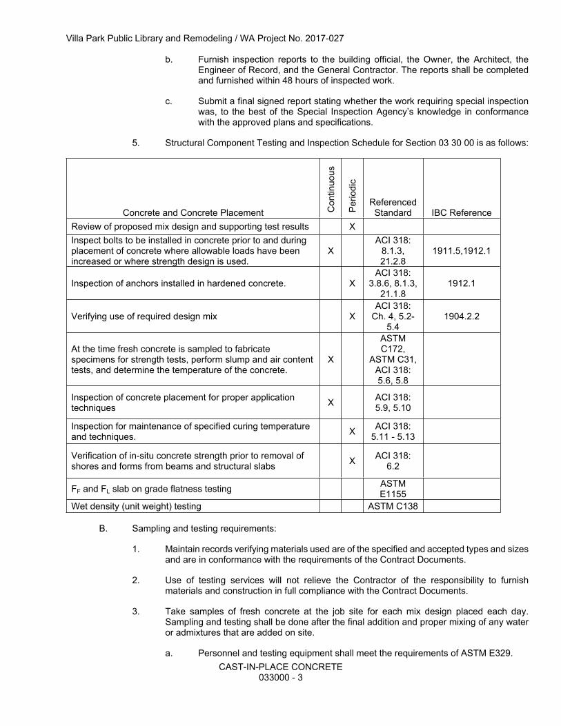
b. Furnish inspection reports to the building official, the Owner, the Architect, the Engineer of Record, and the General Contractor. The reports shall be completed and furnished within 48 hours of inspected work.
c. Submit a final signed report stating whether the work requiring special inspection was, to the best of the Special Inspection Agency’s knowledge in conformance with the approved plans and specifications.
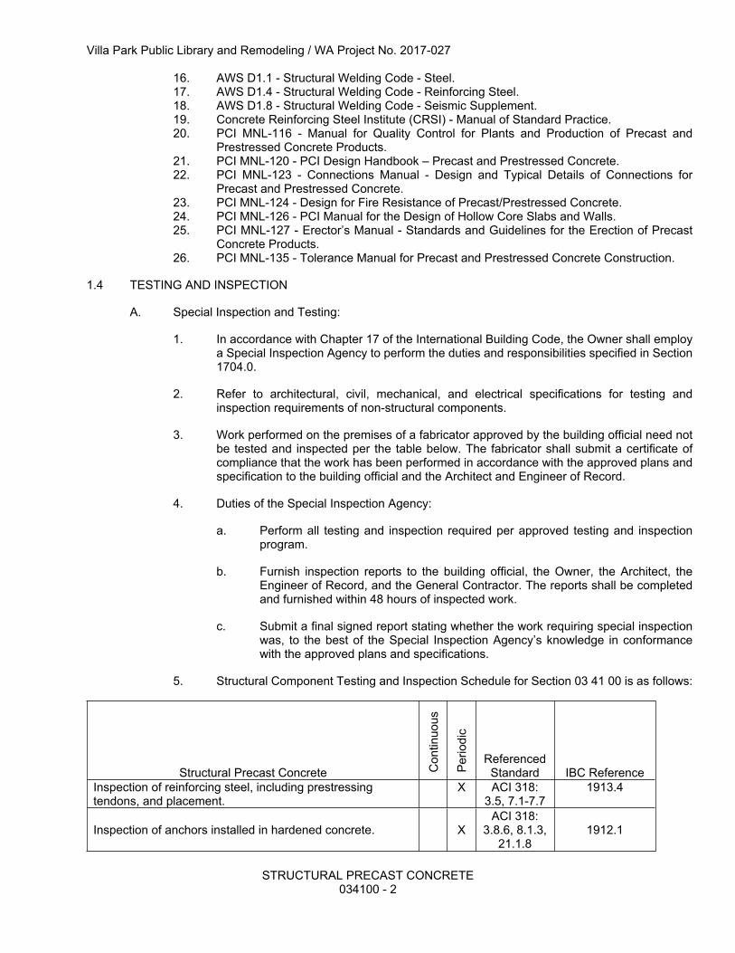
5. Structural Component Testing and Inspection Schedule for Section 05 12 23 is as follows:
Villa Park Public Library and Remodeling / WA Project No. 2017-027
STRUCTURAL STEEL051223 - 3
Structural Steel Con
tinuo
us
Perio
dic
Referenced Standard
IBC Reference
1. Material verification of high-strength bolts, nuts, and washers:
A. Identification markings to conform to ASTM standards specified in the approved construction documents.
X Applicable ASTM material standards: AISC 360, Section
A3.3B. Manufacturer’s certificate of compliance required. X
2. Inspection of high-strength bolting:A. Snug-tight joints. XB. Pretensioned and slip-critical joints using turn-of-nut with matchmarking or direct tension indicator methods of installation.
X
C. Pretensioned and slip-critical joints using turn-of-nut without matchmarking or calibrated wrench methods of installation.
X
AISC 360, Section M2.5 1704.3.3
3. Material verification of structural steel:
A. Identification markings to conform to AISC 360. X AISC 360, Section M5.5
B. Manufacturer’s certified test reports. X4. Material verification of weld filler materials:
A. Identification markings to conform to AWS specification in the approved construction documents.
X AISC 360, Section A3.5 and applicable
AWS A5 documents
B. Manufacturer’s certificate of compliance required X5. Inspection of welding:
A. Complete and partial joint penetration groove welds X AWS D1.1 1704.3.1B. Multi-pass fillet welds X AWS D1.1 1704.3.1C. Single-pass fillet welds > 5/16” (7.9 mm) X AWS D1.1 1704.3.1D. Plug and slot welds. X AWS D1.1 1704.3.1E. Single-pass fillet welds 5/16” (7.9 mm) X AWS D1.1 1704.3.1
6. Inspection of steel frame joint details for compliance:A. Details such as bracing and stiffening. X 1704.3.2B. Member locations. X 1704.3.2C. Application of joint details at each connection. X 1704.3.2
1.5 QUALITY ASSURANCE
A. Fabrication, Erection, and Welding Qualifications:
1. Fabricate structural steel members in accordance with AISC Specification for the design, fabrication and erection of structural steel for buildings.
2. Steel fabricator shall not have less than five (5) years of continuous experience in fabrication of structural steel framing.
3. Steel detailer shall have five (5) years of continuous experience in the production of steel fabrication drawings.
Villa Park Public Library and Remodeling / WA Project No. 2017-027
STRUCTURAL STEEL051223 - 4
4. Steel erector shall not have less than five (5) years of continuous experience in the erection of structural steel framing.
5. All welding of structural steel shall be performed by operators who have been recently qualified as prescribed in “Qualification Procedures” of the American Welding Society (AWS).
6. Tolerances: Tolerances shall be as indicated by the AISC Code of Standard Practice for Buildings and Bridges, except that tolerances for fabricating, rolling, cambering and erection shall not be cumulative.
1.6 SUBMITTALS
A. Shop Drawings:
1. Prepare and submit complete erection and detailed shop drawings for Engineer’s approval, including framing plans indicating size, weight and location of all structural members. Shop drawings shall indicate methods of connecting, anchoring, fastening, bracing and attaching work of other trades.
a. Where contract documents indicate verify in field (VIF) dimensions, shop drawings shall indicate these dimensions and Contractor shall note that the dimensions have been verified.
b. This specification modifies AISC Code of Standard Practice by deleting the following sentence from 4.4.1(c): “Release by the Owner’s Designated Representatives for Design and Construction for the Fabricator to begin fabrication using the approved submittals.” Review of the shop drawings by the Engineer shall not relieve the fabricator of this responsibility.
2. Furnish both the Engineer and Architect with one copy of the following:
a. Final shop drawings containing all review notations.b. Field Use/For Construction drawings.
3. The steel fabricator shall submit a setting plan for all embedded items for Engineer’s approval.
4. Welder’s Certification: Submit certification for all welders employed on the project demonstrating they have been AWS qualified to perform the welding procedures required for this project.
5. General Contractor/Construction Manager to provide copies of field concrete cylinder breaks indicating the concrete meets 75% of the design compressive strength to the steel erector.
B. The General Contractor shall conduct a field survey of as-built anchors and bearing plate locations and elevations prior to steel erection. Survey shall be furnished to the steel fabricator. Contractor shall identify deviations from approved shop drawings and submit proposed repairs and modifications to the Engineer and steel fabricator for approval.
C. Product Data:
1. Certified copies of material test reports, commonly called mill test reports, for all structural steel used on the project. Material test reports shall comply with the requirements of ASTM A6, shall cover chemical and physical properties, and shall be accompanied by a Certificate of Compliance from the fabricator.
Villa Park Public Library and Remodeling / WA Project No. 2017-027
STRUCTURAL STEEL051223 - 5
2. Manufacturer specifications, certifications, and installation recommendations for the following products, including laboratory test reports and other data required to prove compliance with these specifications:
a. High strength bolts, including nuts and washers.b. Unfinished bolts and nuts
3. The Contractor shall submit written procedures for the pre-installation testing, installation, snugging, pretensioning, and post-installation inspection of fasteners. The procedure(s) shall meet all requirements of the RCSC specification and the drawings. Procedures need to be submitted only for the method(s) of installation to be used by the Contractor, which may include the turn-of-nut, calibrated wrench, twist-off type tension control bolt, and direct tension indicator methods.
4. Shear Connectors: Contractor shall submit the following:
a. Certifications that the studs, as supplied, meet the requirements of AWS D1.1, Sections 7.2 and 7.3.
b. Certified copies of the stud manufacturer’s test reports covering the last completed set of in-plant quality control mechanical tests for the diameter supplied.
c. Certified material test reports from the steel supplier indicating diameter, chemical properties, and grade on each heat number supplied.
d. Certificate of Compliance from the Contractor.
5. Prepare and submit product data for Engineer’s approval for shop applied primers, finished paint system, expansion and/or adhesive anchors, non-shrink grout and other miscellaneous materials.
1.7 DELIVERY, STORAGE AND HANDLING
A. Steel members shall be transported, stored and erected in a manner that will avoid any damage or deformation. Materials should be stored to allow easy access for inspection and identification. Bent or deformed members will be rejected and shall be replaced or repaired at the expense of the responsible party. Store clear of the ground and in such a manner as to eliminate excessive handling.
B. Store fasteners in a protected location. Clean and re-lubricate bolts and nuts before use.
PART 2 - PRODUCTS
2.1 MATERIALS
A. Structural Steel:
1. All structural steel shall be free from defects impairing strength, durability or appearance. All structural steel shall meet the latest minimum requirements as follows:
a. Structural steel wide flange shapes shall:
1) Conform to the ASTM designations listed in the General Notes of the drawings, unless noted otherwise.
b. Structural steel angles, channels, bars, plates, and miscellaneous shall conform to the ASTM designations listed in the General Notes of the drawings.
Villa Park Public Library and Remodeling / WA Project No. 2017-027
STRUCTURAL STEEL051223 - 6
1) Shapes of ASTM A572, Grade 50, mill certified to AISC Technical Bulletin #3 requirements, may be substituted for A992 with approval from the Structural Engineer of Record (SEOR).
2) Grade 50 steel shall have a minimum yield stress of 50 ksi and the yield stress, Fy, that is reported from tests shall be based on the yield strength definition in ASTM A370, using the offset method at 0.002 strain.
c. Square and rectangular structural tubing shall be cold formed conforming to the ASTM designations listed in the General Notes of the drawings.
d. Round structural tubing shall be cold formed conforming to the ASTM designations listed in the General Notes of the drawings.
e. Steel pipe shall conform to the ASTM designations listed in the General Notes of the drawings.
B. High Strength Structural Bolts:
1. High strength structural bolts shall conform to the ASTM designations listed in the General Notes of the drawings.
2. High strength bolts shall be detailed and installed in accordance with AISC - “Specification for Structural Joints Using ASTM A325 or A490 Bolts.”
3. Manufacturer’s symbol and grade markings shall appear on all bolts and nuts.
C. Anchoring Devices:
1. Anchor Rods: Anchor rods used with structural steel members shall be plain threaded rods conforming to the ASTM designations listed in the General Notes of the drawings.
2. Expansion Anchors: Expansion anchors shall consist of one-piece wedge type carbon steel anchors with heavy-duty nuts and washers. All components shall be zinc plated in accordance with ASTM B633. Refer to the drawing details and General Notes for the expansion anchors used as the basis of design and the acceptable alternates.
3. Adhesive Anchoring System: Adhesive anchoring system shall consist of a threaded anchor rod complete with nut and washer and the adhesive cartridge. Refer to the drawing details and General Notes for the adhesive anchoring systems used as the basis of design and the acceptable alternates.
a. Nuts shall meet ASTM A563, Grade DH, and washers shall meet ASTM F436.
b. All components shall be zinc plated in accordance with ASTM B633 SC1.
c. Adhesive shall consist of a two-part acrylic based adhesive applied in a dual cartridge dispensing system that properly mixes the components at the point of application.
D. Welding Materials:
1. Type required for material being welded in conformance with AWS D1.1.
Villa Park Public Library and Remodeling / WA Project No. 2017-027
STRUCTURAL STEEL051223 - 7
E. Stud Connectors:
1. For threaded studs that are being used to connect steel beams to embed plates, use ASTM A108, Type A, Grades 1010 through 1020 forged steel, headed uncoated with a minimum tensile strength of 61,000 psi. Fabricated within the tolerances set forth in AWS D1.1.
2. For shear connectors that are being used on steel beams in concrete slabs for composite shear transfer and embedded steel members, use ASTM A108, Type B, Grades 1010 through 1020 forged steel, headed uncoated with a minimum tensile strength of 65,000 psi. Fabricated within the tolerances set forth in AWS D1.1
3. Studs applied by means of the electric arc welding process and shall use an arc shield ferrules of heat resistant ceramic.
F. Galvanizing: Where indicated on the drawings, steel shall be galvanized by the hot-dip process after fabrication conforming to ASTM A123. All exterior steel that will remain exposed shall be galvanized, unless otherwise indicated.
G. Paints and Primers:
1. Fabricator’s standard lead- and chromate-free, non-asphaltic, rust-inhibiting primer. 2. Galvanizing repair paint: SSPC Paint 20. 3. Refer to Specification Section 09 90 00 for additional paint requirements.
H. Non-Shrink Grout for Base and Bearing Plates: Non-shrink grout, conforming to ASTM C1107, shall be pre-mixed, non-metallic, non-corrosive, non-staining product containing selected silica sand, Portland cement, shrinkage compensating agents, plasticizing and water reducing agents. All constituents shall meet the requirements of these specifications. Minimum compressive strength at 28-days shall be 7,000 psi as determined by ASTM C109. Follow manufacturer’s instructions for handling, mixing, placing and curing. Acceptable products are:
1. Euclid Chemical Company - Euco N.S. Grout2. L&M Construction Chemical - Crystex.3. Master Builders - Masterflow 713.4. Sonneborn - Sonnogrout.5. Five Star Products Inc. – Five Star Grout.6. Dayton Superior - Sure-Grip High Performance Grout.7. Dayton Superior – 1107 Advantage Grout.
2.2 FABRICATION AND MANUFACTURE
A. Fabrication Procedures (non-AESS):
1. Fabricate all structural steel items in accordance with AISC Specifications and as indicated on the approved shop drawings.
2. Provide camber in structural members where indicated.
3. Properly mark materials for field assembly and location for which intended. Fabricate for delivery sequence that will expedite erection and minimize handling of materials.
4. Complete structural steel assemblies before shop priming or galvanizing.
B. Shop Connections:
1. All shop connections shall be welded, unless noted otherwise on drawings. Connections shall develop the full strength of the adjoining members unless detailed otherwise.
Villa Park Public Library and Remodeling / WA Project No. 2017-027
STRUCTURAL STEEL051223 - 8
2. All holes shall be either drilled or punched, as no burning of holes will be permitted, including the enlargement of holes. Provide all holes required for connections and for attaching the work of other trades where such holes are shown if furnished prior to fabrication.
3. Connections shall be detailed as standard framed beam connections (bearing type) in accordance with the AISC Manual of Steel Construction - Allowable Stress Design. Connections which require oversized holes or slotted holes in which the force is other than normal to the axis of the slot shall be detailed as “Slip-Critical Connections” and noted as such on the erection drawings. Provide bearing plates and end anchorage for beams resting on masonry.
4. All full and partial penetration welds shall be fully detailed on the shop drawings. Use backing for all full penetration welds.
5. Weld access holes shall be fabricated in accordance with the recommendations of AWS D1.1 and AISC Specification.
C. Shear Connectors:
1. Steel stud shear connectors shall be securely welded in the field to structural steel beams as detailed on the drawings. Welds shall be such that the shear connector stud will deform before weld failure occurs. Welding shall be done in accordance with AWS D1.1.
2. Shear stud connector for embedded plates and angles shall be welded in the fabrication shop in accordance with AWS D1.1.
D. Deck support framing and seats: Furnish all miscellaneous framing necessary to fully support the roof and floor steel decking.
2. The following surfaces are exceptions to shop priming:
a. Surfaces embedded in concrete or mortar. Extend priming of partially embedded members to a depth of 2 inches.
b. Surfaces to be field welded.c. Surfaces to be high-strength bolted with slip-critical connections.d. Top flanges of beams supporting composite steel decking.e. Surfaces to receive sprayed fire-resistive materials.f. Galvanized surfaces.
3. Surface Preparation: Clean Surfaces to be painted. Remove loose rust and mill scale and spatter, slag, or flux deposits. Prepare surfaces according to the following specifications and standards:
a. SSPC-SP3, “Power Tool Cleaning.”
4. Priming: Apply primer in accordance with paint manufacturer’s recommendations, and at a rate recommended by SSPC to provide a dry film thickness of not less than 1.5 mils. Use priming methods that result in full coverage of joints, corners, edges, and exposed surfaces.
Villa Park Public Library and Remodeling / WA Project No. 2017-027
STRUCTURAL STEEL051223 - 9
F. Finished Paint System:
1. Finished paint coats shall be in accordance with paint manufacturer’s recommendations, and specification Division 9.
2. Paint shall be free of sags, runs, drips or other defects. Allow ample drying time before handling to prevent damage to coatings.
3. Strip paint corners, crevices, bolts, welds, and sharp edges.
4. Apply two coats of shop paint to surfaces that will be inaccessible after assembly or erection. Change color of the second coat to distinguish it from the first.
G. Galvanizing:
1. Hot-Dip Galvanized Finish: Apply Zinc coating by the hot-dip process to structural steel according to ASTM A 123.
a. Fill vent holes and grind smooth after galvanizing.
b. Unless otherwise noted on drawings or in Division 9, all exterior steel components exposed to the elements shall be galvanized, including, but not limited to, lintels.
PART 3 - EXECUTION
3.1 SURFACE CONDITIONS
A. Examine the areas and conditions under which work of this Section will be performed. Correct conditions detrimental to timely and proper completion of the Work. Do not proceed until unsatisfactory conditions have been corrected.
3.2 ERECTION
A. Erection Procedures:
1. The erector and not the SEOR shall be responsible for the means, methods and safety of erection of the structural steel framing.
2. Erection of all structural steel items shall meet the requirements of AISC “Specification and Code of Standard Practice.”
3. All work shall be erected square, plumb, straight and true, accurately fitted and with tight joints and intersections, by mechanics experienced in the erection of structural steel. Make allowances for difference between temperature at time of erection and mean temperature when structure is completed and in service.
4. Clean the bearing surface and other surfaces that will be in permanent contact before assembly.
5. All base plates shall be supported on steel wedges, steel shims or heavy duty leveling nuts until the supported members have been leveled and plumbed.
a. Snug tighten anchor rods after supported members have been positioned and plumb. Do not remove wedges or shims but, if protruding, cut off flush with edge of base plate before packing with grout.
Villa Park Public Library and Remodeling / WA Project No. 2017-027
STRUCTURAL STEEL051223 - 10
b. Promptly place non-shrink grout between bearing surfaces and base plates so no voids remain. Neatly finish exposed surfaces; protect grout and allow to cure. Comply with manufacturers written installation instructions for shrinkage-resistant grouts.
6. Field connections of structural work shall be made with either high strength bolts (bearing type) or by welding. Proper precaution shall be taken to ensure that anchored items will not be distorted or overstressed due to improperly fabricated items.
7. Splice members only where indicated unless, with the SEOR’s approval, splices not indicated would result in lower costs due to reduced shipping expense. For splices not indicated, submit structural calculations prepared under direct supervision of and signed by a Structural Engineer licensed in the state where the project is located.
8. Do not use thermal cutting during erection unless approved by the Engineer/Architect in writing.
9. Steel erection shall not proceed without concrete in footings, piers, and walls attaining 75% of the intended minimum compressive design strength. Documentation must be provided indicating compliance with this requirement.
B. Surveys:
1. Establish permanent benchmarks necessary for accurate erection of structural steel.
2. Check elevations of concrete surfaces, and locations of anchor bolts and similar items, before erection proceeds.
C. Bracing and Protection:
1. Steel shall be well plumbed, leveled and braced to prevent any movement.
a. Contractor shall provide and maintain all necessary temporary guying of steel frame to resist safely all wind and construction loads during erection and to assure proper alignment of all parts of the steel frame.
2. Provide all temporary flooring, bracing, shoring and guards necessary to prevent damage or injury. All partially erected steel shall be secured in an approved manner during interruptions of work.
D. Anchor and Foundation Rods:
1. All anchor or foundation rods and similar steel items to be built into concrete or masonry are to be set by the concrete or masonry contractors and shall be furnished promptly so that they may be built in as the work progresses because cutting of structural steel members to accommodate errors pertaining to embedded items will not be permitted.
3.3 FIELD WELDING
A. Welding Procedures:
1. All field welding shall be in accordance with AISC Specifications and conform to AWS D1.1 “Structural Welding Code - Steel”.
a. Comply with AISC’s “Code of Standard Practice for Steel Buildings and Bridges” for bearing, adequacy of temporary connections, alignment, and removal of paint on surfaces adjacent to field welds.
Villa Park Public Library and Remodeling / WA Project No. 2017-027
STRUCTURAL STEEL051223 - 11
b. Assemble and weld built-up sections by methods that will maintain true alignment of axes without exceeding tolerances of AISC’s “Code of Standard Practice” for Steel Buildings and Bridges” for mill material.
2. Contractor shall remove ceramic ferrules from shear connectors in sufficient time to allow for inspection of welds prior to placement of the concrete.
3.4 REPAIRS, PROTECTION, AND TOUCH UP
A. Repair damaged galvanized coatings and on galvanized items with galvanized repair paint according to ASTM A780 and manufacturer’s written instructions.
B. Touch up Painting: After installation, promptly clean, prepare, and prime or reprime field welds, final connections, rust spots, and abraded surfaces of prime-painted joists, bearing plates and abutting structural steel.
1. Clean and prepare surfaces by SSPC-SP2 hand-tool cleaning or SSPC-SP3 power-tool cleaning.
2. Apply a compatible primer of the same type as shop primer used on adjacent surfaces.
3. Secure approval by the Architect prior to field painting.
3.5 GROUTING
A. Grouting under structural framing members shall be completed after all members have been plumbed and braced and before imposed loads are placed thereon.
B. Remove all defective concrete, dirt, oil, grease and other foreign matter from surfaces to which grout will be placed.
3.6 MISCELLANEOUS STEEL AND STEEL LINTELS
A. Furnish and install all miscellaneous steel as detailed in architectural and structural drawings.
B. The steel fabricator shall furnish all steel lintels required for masonry wall construction indicated in the architectural and structural drawings and schedules.
C. Provide additional steel framing for continuous support of steel deck edges at openings and column interruptions.
D. All exterior exposed steel shall be hot-dip galvanized in accordance with ASTM A123 painted in accordance with Division 9 after fabrication.
END OF SECTION
Villa Park Public Library and Remodeling / WA Project No. 2017-027
CONCRETE FORMWORK053100 - 1
SECTION 053100STEEL DECK
PART 1 - GENERAL
1.1 SECTION INCLUDES
A. Fabrication and erection of steel deck. The Work shall include, but not be limited to the following:
A. Codes and Standards: Comply with the provisions of the following codes, specifications and standards, except where more stringent requirements are shown or specified. Where any provisions of other pertinent codes and standards conflict with this specification, the more stringent provision shall govern.
1. AISI S100 - North American Specification for the Design of Cold-Formed Steel Structural Members.
2. ASCE 9 - Standard for the Structural Design of Composite Slabs and Standard Practice for Construction and Inspection of Composite Slabs.
3. ASTM A36 - Standard Specification for Carbon Structural Steel.4. ASTM A108 - Standard Specification for Steel Bar, Carbon and Alloy, Cold-Finished.5. ASTM A653 - Standard Specification for Steel Sheet, Zinc Coated (Galvanized) or Zinc-
Iron Alloy-Coated (Galvannealed) by the Hot-Dip Process.6. ASTM A924 - Standard Specification for General Requirements for Steel Sheet, Metallic-
Coated by the Hot-Dip Process.7. ASTM A1008 - Standard Specification for Steel, Sheet, Cold-Rolled, Carbon, Structural,
High-Strength Low-Alloy, High-Strength Low-Alloy with Improved Formability, Solution Hardened, and Bake Hardenable.
1. In accordance with Chapter 17 of the International Building Code, the Owner shall employ a Special Inspection Agency to perform the duties and responsibilities specified in Section 1704.0.
Villa Park Public Library and Remodeling / WA Project No. 2017-027
CONCRETE FORMWORK053100 - 2
2. Refer to architectural, civil, mechanical, and electrical specifications for testing and inspection requirements of non-structural components.
3. Work performed on the premises of a fabricator approved by the building official need not be tested and inspected per the table below. The fabricator shall submit a certificate of compliance that the work has been performed in accordance with the approved plans and specification to the building official and the Architect and Engineer of Record.
4. Duties of the Special Inspection Agency:
a. Perform all testing and inspection required per approved testing and inspection program.
b. Furnish inspection reports to the building official, the Owner, the Architect, the Engineer of Record, and the General Contractor. The reports shall be completed and furnished within 48 hours of inspected work.
c. Submit a final signed report stating whether the work requiring special inspection was, to the best of the Special Inspection Agency’s knowledge in conformance with the approved plans and specifications.
5. Structural Component Testing and Inspection Schedule for Section 05 31 00 is as follows:
Steel Deck Con
tinuo
us
Perio
dic
Referenced Standard
IBC Reference
1. Material verification of cold-formed steel deck:
A. Identification markings to conform to ASTM standards specified in the approved construction documents.
X Applicable ASTM material standards
B. Manufacturer’s certified test reports. X2. Inspection of welding:
A. Floor and roof deck welds X AWS D1.3
1.5 QUALITY ASSURANCE
A. Fabricator: Company specializing in performing the work of this section with minimum five (5) years documented experience at manufacturing steel deck. Fabrication Company shall be a current member of the Steel Deck Institute (SDI).
B. Erector: Company specializing in performing the work of this section with minimum five (5) years documented experience at erecting steel deck.
C. Welding: Qualify Welding Procedure Specifications (WPS) and welding operators in accordance with AWS D1.3. Provide certifications that welders to be employed in the construction have satisfactorily passed AWS qualification tests. If recertification of welders is required, retesting will be the contractor’s responsibility.
D. Furnish and install steel deck in accordance with the manufacturer’s current ICC Research Committee Report to obtain diaphragm values indicated.
1.6 SUBMITTALS
A. Prepare and submit shop drawings for Engineer’s approval. Shop drawings shall indicate deck layout, depth, uncoated metal thickness, framing and supports with unit dimensions and sections,
Villa Park Public Library and Remodeling / WA Project No. 2017-027
CONCRETE FORMWORK053100 - 3
shear stud layout and complete end jointing. Contractor to verify measurements, lines, elevations, and details of field conditions to conform with actual conditions.
B. Provide details of all accessories.
C. Shop drawings shall also indicate typical welding or mechanical anchoring pattern for steel deck and accessories.
D. Prepare and submit allowable construction span tables and allowable total load tables for Engineer’s approval. Tables shall be accompanied with a letter of certification from the manufacturer stating the tabulated design values were determined in accordance with the Steel Deck Institute’s Design Manuals for Roof Deck, Floor Deck and Diaphragm Design.
1. The gauges and section moduli indicated on the drawings or specified herein are minimum and the gauge and section modulus of the deck furnished shall meet or exceed these minimum requirements. All gauges are United States standard, measured prior to coating.
E. WPS and Procedure Qualification Records (PQR) shall be current and approved by the Structural Engineer of Record (SEOR).
F. Provide manufacturer’s latest recommendations and installation instructions.
G. Prepare and submit product data of proposed materials.
1.7 DELIVERY, STORAGE AND HANDLING
A. All decking materials shall be transported, stored and erected in a manner that will prevent damage or deformation of sheets. Damaged material shall not be erected or repaired without Structural Engineer’s approval.
B. Deck panels shall be stored clear of the ground, elevated on one end, and protected from weather with waterproof covering.
PART 2 - PRODUCTS
2.1 STEEL ROOF DECK
A. Standard Steel Roof Deck: Fabricate panels to comply with the “SDI Roof Deck Design Manual,” and the following:
1. Steel decking sheet material, minimum yield strength, depth, gage, profile, and finish are indicated on the drawings, as classified by Steel Deck Institute (SDI). Panels shall be formed with integral ribs and overlapping side flanges.
2. Galvanized Steel Sheet: ASTM A653 Structural Steel (SS), Grade 33, with a G60 G90 zinc coating conforming to ASTM A924 for galvanized deck.
2.2 COMPOSITE FLOOR DECK
A. Composite Floor Deck: Fabricate panels with integrally embossed or raised pattern ribs to comply with the “SDI Floor Deck Design Manual,” and the following:
1. Steel decking sheet material, minimum yield strength, depth, gage, profile, and finish are indicated on the drawings, as classified by Steel Deck Institute (SDI). Panels shall be formed with integral ribs and overlapping side flanges.
Villa Park Public Library and Remodeling / WA Project No. 2017-027
CONCRETE FORMWORK053100 - 4
2. Galvanized Steel Sheet: ASTM A653 Structural Steel (SS), Grade 33, with a G60 G90 zinc coating conforming to ASTM A924 for galvanized deck.
2.3 FASTENERS
A. Support Fasteners:
1. Welded: Refer to drawings for weld size and spacing requirements.
a. Shear studs may replace support fasteners. Refer to drawings for requirements.
1) Provide headed stud type of cold finished carbon steel per Section 05 12 23.
2) Use ferrules suitable for use with galvanized steel deck.
b. Weld washers required for material less than 0.028" thick. Welding washers shall a minimum thickness of 0.0598 inches and be applicable to AWS D1.3 type welding and of type as recommended by the deck manufacturer.
c. Weld metal shall penetrate all layers of deck material and shall have good fusion to the supporting steel. Fasten ribbed deck to steel support members at ends and intermediate supports.
1) All welding shall be in conformance with previously cited AWS recommendations in appearance and quality of welds, and the methods used in correcting welding work.
B. Side Lap Fasteners:
1. Mechanical: Zinc coated self-drilling, self-tapping type (minimum No. 10) steel screws. Refer to drawings for fastener spacing requirements.
2.4 ACCESSORIES
A. Steel materials to conform to ASTM A108 meeting the requirements of ASTM A653, G60 coating.
B. Provide all closers, fillers, starters, sump pans, metal cant strips, ridge and valley plates, pour stops, column closures, girder fillers, and similar accessories required for a complete installation. Provide cover plates at all locations where direction of deck span changes. Unless otherwise noted, accessories shall be of the same steel sheet material, finish, and thickness as the deck sections.
PART 3 - EXECUTION
3.1 ERECTION
A. Verify that field conditions are acceptable and are ready to receive work. Correct inaccuracies in alignment or level before deck units are finally placed.
B. Deck units and deck accessories herein specified shall be thoroughly and securely erected by experienced workmen fastening to supporting steel members as herein specified. All work shall be in conformance with manufacturer’s latest printed recommendations and approved shop drawings.
C. Beginning of installation means installer accepts existing conditions.
D. The finished work shall be true, flat planes and to slopes indicated with end joints flush and without sharp protruding edges. Exposed underside of deck shall be true without defect.
Villa Park Public Library and Remodeling / WA Project No. 2017-027
CONCRETE FORMWORK053100 - 5
E. Where large predetermined openings for elevators, stairs, ducts, and similar elements passing through the deck units occur, furnish prefabricated units to fit job conditions. Where other holes or openings are required in decking after erection, reinforce such holes as indicated on the drawings. Cantilever deck to the edge of slabs only as indicated on the drawings.
F. Burning of holes in decking will not be permitted.
G. Steel decking shall be installed to span supporting steel members at right angles. Panels shall be securely anchored to each structural support it rests on or passes.
3.2 ROOF DECK
A. Fasten roof deck panels to steel supporting members using welds as specified herein and on the drawings.
B. Deck shall be fastened through the bottom of the deck rib to all structural supports for the specific deck sections.
C. End bearing of roof decking shall have a minimum of 1-1/2 inches of bearing occurring over structural supports
D. Place deck panels on structural supports and adjust to final position with ends aligned. Attach to supports immediately after placement.
E. Roof sump pans shall be installed over openings provided in roof deck with flanges welded to the top of the deck. Space welds at 12 inches apart with at least 1 weld in each corner.
F. Install all roof deck accessories in accordance with the roof deck manufacturer’s written instructions.
3.3 FLOOR DECK
A. Fasten steel floor deck to supporting steel with welds, mechanical fasteners, drive pins, shear studs as specified herein and on the drawings.
B. Unless noted otherwise, secure side laps and perimeter edges of units with fasteners at mid-span between supports or 36 inches on center, whichever distance is smaller.
C. Place deck panels on structural supports and adjust to final position with ends aligned. Attach to supports immediately after placement.
D. Install deck ends over supports with a minimum end bearing of 1-1/2 inches.
E. Install pour stops and girder fillers to supporting structure according to manufacturer’s recommendations.
F. Fasten column closures and cell closures to deck to provide a tight fit. Provide cell closures at changes of direction of deck units, unless otherwise noted.
G. Install all floor deck accessories in accordance with the floor deck manufacturer’s written instructions.
Villa Park Public Library and Remodeling / WA Project No. 2017-027
CONCRETE FORMWORK053100 - 6
3.4 FIELD TOUCH UP
A. After erection, all weld burn marks and abraded spots shall be cleaned and field painted with a rust-inhibiting metal primer matching formulations and color of shop coat or a zinc-rich rust inhibiting paint for galvanized deck surfaces.
END OF SECTION
Villa Park Public Library and Remodeling / WA Project No. 2017-027
CONCRETE FORMWORK031000 - 1
SECTION 031000CONCRETE FORMWORK
PART 1 - GENERAL
1.1 SECTION INCLUDES
A. Design, construction and treatment of formwork and related accessories to confine and shape concrete to the required dimensions.
B. Installation of embedded items such as waterstops.
C. Structural notes indicated on the drawings regarding concrete formwork shall be considered a part of this specification.
1.2 RELATED WORK
A. Pertinent Sections of Division 01.B. Section 03 20 00 - Concrete Reinforcement.C. Section 03 30 00 - Cast-in-Place Concrete.
1.3 REFERENCES
A. Codes and Standards: Comply with the provisions of the following codes, specifications, and standards except where more stringent requirements are shown or specified. Where provisions of the pertinent codes and standards conflict with this specification, the more stringent provision shall govern.
1. ACI 117 - Specification for Tolerances for Concrete Construction and Materials.2. ACI 301 - Specifications for Structural Concrete.3. ACI 318 - Building Code Requirements for Structural Concrete.4. ACI 347 - Guide to Formwork for Concrete.5. ASTM C31 - Standard Practice for Making and Curing Concrete Test Specimens in the
Field.6. ASTM C39 - Standard Test Method for Compressive Strength of Cylindrical Concrete
Specimens.7. NIST - PS 1: Structural Plywood
1.4 TESTING AND INSPECTION
A. Special Inspection and Testing:
1. In accordance with Chapter 17 of the International Building Code, the Owner shall employ a Special Inspection Agency to perform the duties and responsibilities specified in Section 1704.0.
2. Refer to architectural, civil, mechanical, and electrical specifications for testing and inspection requirements of non-structural components.
3. Work performed on the premises of a fabricator approved by the building official need not be tested and inspected per the table below. The fabricator shall submit a certificate of compliance that the work has been performed in accordance with the approved plans and specification to the building official and the Architect and Engineer of Record.
Villa Park Public Library and Remodeling / WA Project No. 2017-027
CONCRETE FORMWORK031000 - 2
4. Duties of the Special Inspection Agency:
a. Perform all testing and inspection required per the Testing and Inspection Schedule indicated below.
b. Furnish inspection reports to the building official, the Owner, the Architect, the Engineer of Record, and the General Contractor. The reports shall be completed and furnished within 48 hours of inspected work.
c. Submit a final signed report stating whether the work requiring special inspection was, to the best of the Special Inspection Agency’s knowledge in conformance with the approved plans and specifications.
5. Structural Component Testing and Inspection Schedule for Section 0310003 10 00 is as follows:
Concrete and Concrete Placement Con
tinuo
us
Perio
dic
Referenced Standard
IBC Reference
Inspect formwork for shape, location and dimensions of the concrete member being formed.
X ACI 318: 6.1.1
1.5 DESIGN REQUIREMENTS
A. Design and engineering of formwork is the responsibility of the Contractor. Design, engineer and construct formwork, shoring, and bracing to conform to Contract Documents and in accordance with building code requirements. Design for construction loads, lateral pressure, and requirements of the applicable building code to conform to the required shape, line and dimensions.
B. Foundation concrete may be placed directly into neat excavations, provided the foundation trench walls are stable as determined by the Geotechnical Engineer. In such case, the minimum formwork indicated on the drawings is mandatory to ensure clean excavations immediately prior to and during the placing of concrete.
1. When forms are omitted, provide additional 1” concrete minimum on each side of the minimum design profiles and dimensions shown on the drawings.
C. Drawings show the design requirements and dimensions for structural strength, but structural drawings do not show all detail dimensions to fit intricate architectural and mechanical detail. Contractor shall so construct the concrete work that it will conform to the clearance required by the architectural, mechanical and electrical design.
D. Maximum deflection of facing materials forming concrete surfaces exposed to view shall be 1/240 of the center-to-center span between structural members of the formwork.
E. Carry vertical and lateral loads to ground by formwork system and in-place construction that has attained adequate strength for that purpose. Where adequate foundations for shores and struts cannot be secured, provide trussed supports.
Villa Park Public Library and Remodeling / WA Project No. 2017-027
CONCRETE FORMWORK031000 - 3
1.6 SUBMITTALS
A. Product Data: Submit manufacturer’s product data, installation instructions and specifications for each of the following:
1. Waterstop profiles2. Form sealer3. Form release agent(s), including certification that agent is compatible with finish4. Form ties and spreaders
B. Testing for Formwork Removal: When methods other than cylinder tests are proposed for determining time for formwork removal, submit data on methods for approval.
PART 2 - PRODUCTS
2.1 MATERIALS AND ACCESSORIES
A. Formwork Accessories: Use commercially manufactured accessories for formwork accessories that are partially or completely embedded in concrete, including ties and hangers.
B. Sealer: Clear, penetrating, synthetic resin sealer.
C. Formwork Release Agent: Use commercially manufactured form release agents that will prevent formwork absorption of moisture, prevent bond with concrete, and will not stain the concrete surface. Reapply to cleaned forms before each reuse. Formwork release agent shall be compatible with paint or any other finish applied to the concrete; submit data indicating compatibility.
D. Waterstops: Waterstops shall be a flexible butyl rubber and bentonite clay compound that swells upon contact with water. Acceptable manufacturer’s and products:
1. No aluminum shall be allowed in the concrete work unless coated to prevent aluminum-concrete reaction.
2. Concrete form materials must be used in a manner to provide the surface finish specified.
3. Design formwork in accordance with the provisions of the building code or the following standards if not covered in the building code:
a. Wood - AF & PA “National Design Specification”.b. Plywood - American Plywood Association “Plywood Design Specification”.c. Steel - AISC “Manual of Steel Construction - Allowable Stress Design”.d. Aluminum - Aluminum Association “Aluminum Construction Manual”.e. Concrete - ACI 318.f. Other materials - as directed by manufacturer.
F. Chamfer Strips:
1. Chamfer strips shall be the size as indicated on the drawings. Provide in maximum possible lengths.
Villa Park Public Library and Remodeling / WA Project No. 2017-027
CONCRETE FORMWORK031000 - 4
2.2 FORM FINISHES
A. Rough Form Finish:
1. Concrete surfaces not exposed to view in the finished work shall have a rough-form finish. No form-facing material is specified for rough-form finish.
2. Set and maintain forms so finished concrete dimensions shall conform to the tolerances. Rough form finish is Designated Surface Finish-1.0 from ACI 301, except that surface tolerance Class C is required as specified in ACI 117.
B. Smooth Form Finish:
1. Concrete surfaces exposed to view in the finished work or surfaces to receive finishes of any type (paint, textured paint, etc.) shall have a smooth form finish. Form-facing material shall be plywood, tempered concrete-form-grade hardboard, metal, plastic, paper, or other acceptable material capable of producing the desired finish. Form-facing material shall produce a smooth, uniform texture on the concrete. Do not use form facing material with raised grain, torn surfaces, worn edges, patches, dents, or other defects that might impair the texture of the concrete surfaces.
2. Set and maintain forms so finished concrete dimensions shall conform to the tolerances. Smooth form finish is Designated Surface Finish-3.0 from ACI 301, including surface tolerance Class A as specified in ACI 117.
C. Patching and repairing concrete finishes are specified under Section 03 30 00.
2.3 FABRICATION AND MANUFACTURE
A. Form Ties and Spreaders: Factory-fabricated, removable or snap-off metal or glass-fiber-reinforced plastic form ties designed to resist lateral pressure of fresh concrete on forms, hold inner and outer forms for vertical concrete together, and to prevent spalling of concrete on removal.
1. Furnish units that will leave no corrodible metal closer than 1-1/2 inch to the plane of the exposed concrete surface.
2. Furnish ties that, when removed, will leave holes not larger than 1 inch in diameter in concrete surface.
3. Furnish ties with integral water-barrier plates to walls indicated to receive dampproofing or waterproofing.
4. At horizontal pour lines, locate ties not more than 6” below the pour lines. Tighten after concrete has set and before the next pour is made.
5. For exposed concrete surfaces, provide form ties of removable type with permanent plugs and a system approved by the Architect for fixing the plugs in place.
B. Waterstops: Fabricate pieces of premolded waterstop with a maximum practicable length to hold the number of end joints to a minimum. Fabricate joints in waterstops in accordance with manufacturer’s recommendations.
Villa Park Public Library and Remodeling / WA Project No. 2017-027
CONCRETE FORMWORK031000 - 5
PART 3 - EXECUTION
3.1 CONSTRUCTION OF TEMPORARY FORMWORK
A. In accordance with ACI 301, construct formwork:
1. Design, erect, shore, brace, and maintain formwork to support vertical, lateral, static, and dynamic loads, and construction loads that might be applied, until concrete structure can support such loads.
2. Obtain approval before framing openings in structural members that are not indicated on the drawings.
B. Fabricate forms for easy removal without hammering or prying against concrete surfaces.
1. Provide crush or wrecking plates where stripping may damage cast concrete surfaces.
2. Provide top forms for inclined surfaces where slope is too steep to place concrete with bottom forms only.
3. Chamfer wood inserts for forming keyways, reglets, recesses, and the like to allow wood to swell without spalling concrete and to ensure easy removal.
C. Falsework:
1. Provide positive means of adjustment (wedges or jacks) of shores and struts. Do not adjust formwork after concrete has taken its initial set. Brace formwork securely against lateral deflection and lateral instability.
2. Verify lines, levels, and centers before proceeding with formwork. Ensure that dimensions agree with the drawings.
3. Fasten form wedges in place after final adjustment of forms and prior to concrete placement.
4. Anchor formwork to shores, supporting surfaces, or members to prevent upward or lateral movement of the formwork system during concrete placement.
5. Securely brace and shore forms to prevent displacement and to safely support construction loads.
6. Construct forms plumb and straight to conform to slopes, lines, and dimensions shown.
7. Set edge forms, bulkheads, and intermediate screed strips for slabs to achieve required elevations and slopes in finished concrete surfaces. Provide and secure units to support screed strips; use strike-off templates or compacting-type screeds.
8. Provide runways for moving equipment and support runways directly on formwork or structural member without resting on the reinforcing steel.
D. Where end-of-work sequence requires a joint in the concrete, provide adequately designed additional formwork. Extend reinforcement through formwork and key joints as indicated on the drawings. Location of the construction joint is subject to approval by the Architect and the SEOR.
E. Construct formwork for wall openings to facilitate removal and to counteract swelling of wood formwork. Keep wood forms wet as necessary to prevent shrinkage.
F. Do not use rust-stained steel form-facing material.
Villa Park Public Library and Remodeling / WA Project No. 2017-027
CONCRETE FORMWORK031000 - 6
G. Provide temporary openings at the base of column and wall formwork and at other points where necessary to facilitate cleaning and inspection.
H. Unless noted otherwise, all footings shall be centered under walls, piers or columns.
I. Provisions for Other Trades:
1. Place sleeves, inserts, anchors, and embedded items required for adjoining work or for support of adjoining work prior to concrete placement.
2. Position and support expansion joint material and other embedded items to prevent displacement. Fill voids in sleeves, inserts, and anchor slots temporarily with readily removable material to prevent entry of concrete into voids.
J. Projecting corners of beams, walls and columns shall be formed with a 3/4-inch chamfer, unless noted otherwise on architectural drawings.
K. Cleaning:
1. Clean surfaces of formwork and embedded materials of mortar, grout, and foreign material before concrete is placed.
2. Cover surfaces of formwork with acceptable formwork release agent. Apply form release agent before placing reinforcing steel and concrete according to manufacturer’s written instructions. Do not allow formwork release agent to puddle in forms. Do not allow formwork release agent to contact reinforcing steel or hardened concrete against which fresh concrete is to be placed. Do not apply form release agent to concrete surfaces receiving special finishes or applied coverings affected by the agent.
3. Clean and inspect formwork immediately before concrete is placed.
L. Hand trim sides and bottom of earth forms. Remove loose soil prior to placing concrete.
M. Install void forms in accordance with manufacturer’s recommendations. Protect forms from moisture or crushing.
3.2 COORDINATION
A. Install all required pipe sleeves, cavities or slots. Notify appropriate trades in due time so that they may furnish information and make necessary installations. Check sizes, location and alignment of all openings, frames and other work, which are to be built-in including electrical boxes and conduit.
B. Layout the run of partitions and establish location of openings so that other trades may properly locate their work.
C. Core drilling concrete is not permitted unless noted otherwise or approved in writing by the Architect. Notify the Architect in advance of conditions not shown on the drawings.
3.3 INSTALLATION OF EMBEDDED ITEMS
A. Built-In Items:
1. Confirm with Architect that all materials to be embedded are suitable for embedment in concrete.
2. Build in anchors, inserts, and other devices indicated or required for various portions of work.
Villa Park Public Library and Remodeling / WA Project No. 2017-027
CONCRETE FORMWORK031000 - 7
3. Build in sleeves, thimbles, and other items furnished or set in place by other trades.
4. Accurately position and support all embedded items prior to concrete placement. Secure embedded items against displacement during concrete placement operations.
5. Fill voids with readily removable material to prevent entry of concrete into voids.
6. Mechanical and electrical shall provide and set required sleeves.
7. Coordinate setting of all embedded items.
B. Waterstops:
1. Locate waterstops in joints where indicated on the drawings.
2. Build in waterstops using longest unbroken lengths possible to hold the number of end splices to a minimum.
3. Form splices and intersections strictly according to the manufacturer’s instructions so that waterstops are continuous and develop effective watertight joint.
4. Locate waterstops as shown on the drawings. In general, waterstops should be located just behind outermost layer of reinforcing. Do not place waterstops closer than 2" from face of concrete.
3.4 TOLERANCES
A. Construction formwork to maintain tolerances required by ACI 301 and ACI 117.
3.5 REMOVAL OF FORMS
A. When removal of formwork is based on concrete reaching a specified compressive strength, concrete will be presumed to have reached this strength when either of the following requirements has been met:
1. Test cylinders, molded and cured under the same conditions for moisture and temperature as used for the concrete they represent, have reached the specified compressive strength.
2. Concrete has been cured in accordance with the specifications for the same length of time as laboratory-cured cylinders, which have reached the specified strength. Determine the length of time concrete has been cured in the structure by the cumulative number of days or fractions thereof, not necessarily consecutive, during which the temperature of the air in contact with the concrete is above 50F and the concrete has been damp or thoroughly sealed from evaporation and loss of moisture.
B. Forms shall remain in place for the following periods of time. These periods represent cumulative number days or hours, not necessarily consecutive, during which the temperature of the air surrounding the concrete is above 50F:
1. Walls, Grade Beams, Columns, Sides of Beams, Girders and Footings: 67% specified compressive strength or minimum 24 hours.
C. When finishing is required, remove forms as soon as removal operations will not damage concrete.
D. Loosen wood formwork for wall openings when this can be accomplished without causing damage to concrete.
Villa Park Public Library and Remodeling / WA Project No. 2017-027
CONCRETE FORMWORK031000 - 8
E. Do not allow removal of formwork to damage the fresh concrete for columns, walls, sides of beams, and other parts supporting the weight of the concrete. Perform needed repair and treatment required on vertical surfaces at once and follow immediately with specified curing.
3.6 REMOVING AND REUSING FORMS
A. Clean and repair surfaces of forms to be reused in the Work. Split, frayed, delaminated, or otherwise damaged form-facing material will not be acceptable for exposed surfaces. Apply new form-release agent.
B. When forms are reused, clean surfaces, remove fins and laitance, and tighten to close joints. Align and secure joints to avoid offsets. Do not use patched forms for exposed concrete surfaces unless approved by Architect
END OF SECTION
Villa Park Public Library and Remodeling / WA Project No. 2017-027
CONCRETE REINFORCEMENT032000 - 1
SECTION 032000CONCRETE REINFORCEMENT
PART 1 - GENERAL
1.1 SECTION INCLUDES
A. Fabrication and placement of reinforcing steel for concrete, and all related accessories.
B. Reinforcing steel for use in bond beams, masonry columns, and lintels is specified in Division 4 and is not a part of the work in this section.
C. Structural notes indicated on the drawings regarding concrete reinforcement shall be considered a part of this specification.
1.2 RELATED WORK
A. Pertinent Sections of Division 01.B. Section 03 10 00 - Concrete Formwork.C. Section 03 30 00 - Cast-in-Place Concrete.
1.3 REFERENCES
A. Codes and Standards: Comply with the provisions of the following codes, specifications and standards, except where more stringent requirements are shown or specified. Where provisions of other pertinent codes and standards conflict with this specification, the more stringent provision shall govern.
1. ACI 117 - Specification for Tolerances for Concrete Construction and Materials.2. ACI 301 - Specifications for Structural Concrete.3. ACI 318 - Building Code Requirements for Structural Concrete.4. ACI SP-066 - ACI Detailing Manual.5. ASTM A184 - Standard Specification for Welded Deformed Steel Bar Mats for Concrete
Reinforcement.6. ASTM A615 - Standard Specification for Deformed and Plain Carbon-Steel Bars for
Concrete Reinforcement.7. ASTM A706 - Standard Specification for Deformed and Plain Low-Allow Steel Bars for
Concrete Reinforcement.8. ASTM A1064 - Standard Specification for Carbon-Steel Wire and Welded Wire
Reinforcement, Plain and Deformed, for Concrete.9. Concrete Reinforcing Steel Institute (CRSI) - Manual of Standard Practice.
1.4 TESTING AND INSPECTION
A. Special Inspection and Testing:
1. In accordance with Chapter 17 of the International Building Code, the Owner shall employ a Special Inspection Agency to perform the duties and responsibilities specified in Section 1704.0.
2. Refer to architectural, civil, mechanical, and electrical specifications for testing and inspection requirements of non-structural components.
3. Work performed on the premises of a fabricator approved by the building official need not be tested and inspected per the table below. The fabricator shall submit a certificate of
Villa Park Public Library and Remodeling / WA Project No. 2017-027
CONCRETE REINFORCEMENT032000 - 2
compliance that the work has been performed in accordance with the approved plans and specification to the building official and the Architect and Engineer of Record.
4. Duties of the Special Inspection Agency:
a. Perform all testing and inspection required per the Testing and Inspection Schedule indicated below.
b. Furnish inspection reports to the building official, the Owner, the Architect, the Engineer of Record, and the General Contractor. The reports shall be completed and furnished within 48 hours of inspected work.
c. Submit a final signed report stating whether the work requiring special inspection was, to the best of the Special Inspection Agency’s knowledge in conformance with the approved plans and specifications.
5. Structural Component Testing and Inspection Schedule for Section 03 20 00 is as follows:
Concrete and Concrete Placement Con
tinuo
us
Perio
dic
Referenced Standard IBC Reference
Inspection of fabricators and during fabrication. X 1704.2Inspection of reinforcing steel and placement. X ACI 318: 3.5,
7.1-7.71913.4
1.5 SUBMITTALS
A. Placing Drawings: Submit placing drawings showing fabrication dimensions and locations for placement of reinforcement and reinforcement accessories. Indicate bar sizes, spacing, locations, and quantities of reinforcing steel, bending and cutting diagrams, anchors, and supporting and spacing devices. Dowels shall be shown in placing drawings for the element that is to be placed first. Reinforcing steel descriptions or shop drawings shall be inch-pound sizes.
B. Manufacturer’s Certifications:
1. Submit mill certifications at time of delivery.2. Submit carbon equivalent (CE) for reinforcing bars to be welded.
C. Splices: Submit request for splices not indicated in the Contract Documents. Request shall indicate locations, types, and lengths of splices for approval.
D. Field Bending: Submit requests and procedure for field bending or straightening of reinforcement partially embedded in concrete not described in the Contract Documents.
E. Reinforcement Relocation: Submit requests to adjust reinforcement spacing necessitated by conflicts with other reinforcement, conduits, etc. for approval.
1.6 COORDINATION
A. Coordinate reinforcement installation with the placement of formwork and other embedded items such as inserts, conduit, pipe sleeves, drains, metal supports, anchor rods, etc.
Villa Park Public Library and Remodeling / WA Project No. 2017-027
CONCRETE REINFORCEMENT032000 - 3
1.7 DELIVERY, STORAGE AND HANDLING
A. Deliver reinforcement to the jobsite in bundles sorted and labeled with durable tags indicating bar size, length, and shop drawing mark. Bundles shall also bear testing laboratory tags indicating identified steel.
B. Store elevated clear of ground and protect at all times from contamination and deterioration.
C. Prevent bending, coating with earth, oil, or other material, or otherwise damaging the reinforcement.
D. Store welding electrodes in accordance with the requirements of AWS D1.4.
PART 2 - PRODUCTS
2.1 MATERIALS
A. Bar Deformations: Bars used for reinforcement shall be deformed except column spirals and welded wire reinforcement, which may be plain.
B. Reinforcing Steel: Reinforcing steel shall conform to the ASTM standard and grade indicated in the General Notes on the drawings.
C. Welded Wire Reinforcement: Welded wire reinforcement shall conform to the ASTM standard indicated in the General Notes on the drawings.
D. Joint Dowel Bars: Plain-steel bars. Cut bars true to length with square ends and free of burrs.
E. Bar Supports: Bolsters, chairs, spacers, and other devices for spacing, supporting, and fastening reinforcing bars and welded wire reinforcement in place. Manufacture bar supports according to CRSI's "Manual of Standard Practice" from steel wire, plastic, or precast concrete or fiber-reinforced concrete of greater compressive strength than concrete, and as follows:
1. For concrete surfaces exposed to view where legs of wire bar supports contact forms, use CRSI Class 1 plastic-protected or CRSI Class 2 stainless-steel bar supports.
2. Concrete cast against earth: Bars may be supported by precast concrete bricks or approved prefabricated wire bar supports complying with CRSI recommendations with footpads large enough to support the weight of the bars and construction traffic without being pushed into underlying grade. Precast concrete blocks shall have a minimum compressive strength of 6,000 psi.
2.2 FABRICATION
A. Fabrication Tolerances: Reinforcing steel shall be shop fabricated within tolerances according to ACI 117 and other applicable codes, and shall conform in size, shape, quantity, dimensions, etc. to the construction drawings and approved shop drawings.
B. Bar Condition: Bars shall be free from mill scale, excessive rust and other coatings, which would reduce or destroy the bond with the concrete. Wipe oil from forms before reinforcement is placed on or adjacent to so that oil will not be tracked over or in any way come into contact with the reinforcement.
C. Bars Bending: Bars shall be bent cold, and no method of fabrication shall be used which would be injurious to the material. Heating of bars for bending is not permitted.
D. Identification: After fabrication, bars shall be sorted, bundled and tagged with metal tags bearing the bar mark before delivery to the jobsite.
Villa Park Public Library and Remodeling / WA Project No. 2017-027
CONCRETE REINFORCEMENT032000 - 4
E. Corner Bars: Provide corner bars to make reinforcing continuous at all times, including intersections at footings, walls, beams or caps. Such bars shall be the same size and spacing as the horizontal reinforcing and each leg shall have a length of at least 30 inches.
F. Splicing:
1. Continuous reinforcing in beams and grade beams shall be lapped as follows unless noted otherwise:
a. Top bars Midspanb. Bottom bars Directly over support
2. Locate reinforcing splices not indicated on drawings at point of minimum stress. Review location of splices with the SEOR and obtain written approval prior to proceeding.
G. Where beams and grade beams are simple span, top bars shall be continuous for full length and hooked down at each end.
H. Reinforcing for continuous footings shall extend into spread footings a minimum of 2'-0".
I. Dowels between footings and walls or columns shall be the same grade, size and spacing or number as the vertical reinforcing respectively, unless noted otherwise.
PART 3 - EXECUTION
3.1 PLACING
A. Reinforcement Relocation: When necessary to move reinforcement beyond the specified spacing to avoid interference with other reinforcement, or embedded items, submit resulting arrangement of reinforcement to SEOR for approval.
B. Reinforcement Cutting: Cutting of reinforcement which conflicts with embedded objects is not acceptable.
C. Welded Wire Reinforcement: Extend welded wire reinforcement to within 1 inch of the concrete edge. Lap edges and ends of fabric sheets a minimum of two full mesh squares. Lace edges with 16-gauge tie wire. Support welded wire reinforcement during placing of concrete to assure required positioning in the slab. Do not place wire reinforcement on grade or metal deck and raise into position in freshly-placed concrete.
D. Wire Tie Orientation: Set wire ties so that ends are directed away from concrete surface.
E. Slab on Grade Reinforcement Placement: Place shrinkage and temperature reinforcement 2 inches from the top surface of the slabs on grade unless noted otherwise on the drawings.
F. Do not cut, displace, or puncture vapor retarder. Repair damage and reseal vapor retarder before placing concrete.
G. Support for Reinforcement: Unless noted otherwise, supports for reinforcement shall have Class 2 protection as defined in the CRSI Manual of Standard Practice. Submit data on supports indicating class of protection at all different locations for approval. Supports shall not be used as bases for runways for concrete-conveying equipment and similar construction loads. Do not place reinforcing bars more than 2” beyond last leg of any continuous bar support.
H. Support for Bars in Concrete Cast on Ground: Bar supports for slabs on grade, grade beams, footings, and all other concrete cast directly onto grade shall be supported at an average spacing of 4 feet or less in each direction.
Villa Park Public Library and Remodeling / WA Project No. 2017-027
CONCRETE REINFORCEMENT032000 - 5
I. Securing Reinforcing Bars: All bars must be placed, spaced, secured and supported prior to casting concrete. Bars embedded in hardened or partially hardened concrete shall not be bent unless approved in writing prior to placement by the SEOR.
J. Foot Traffic: Restrict foot traffic over the slab on grade reinforcing after it has been properly positioned.
K. Reinforcement at Expansion Joints: Do not continue reinforcement or other embedded metal items bonded to concrete through expansion joints. Dowels bonded on only one side of a joint and waterstops may extend through joint.
L. Pumping Concrete: When using a pump to place concrete, pump hose shall be supported directly on forms. Do not allow hose to rest on reinforcing bars if doing so could cause displacement of bars.
END OF SECTION
Villa Park Public Library and Remodeling / WA Project No. 2017-027
CAST-IN-PLACE CONCRETE033000 - 1
SECTION 033000CAST-IN-PLACE CONCRETE
PART 1 - GENERAL
1.1 SECTION INCLUDES
A. All items required for executing and completing the cast-in-place concrete work and related work shown on the drawings or specified herein. Work shall include installation of items furnished in other sections of these specifications.
B. Concrete paving, walks and curbs are specified in Division 3.
C. Structural notes indicated on the drawings regarding cast-in-place concrete shall be considered a part of this specification.
A. Codes and Standards: Comply with the provisions of the following codes, specifications, and standards, except where more stringent requirements are shown or specified. Where any provision of other pertinent codes and standards conflict with this specification, the more stringent provision shall govern.
1. ACI 117 - Specification for Tolerances for Concrete Construction and Materials.2. ACI 301 - Specifications for Structural Concrete.3. ACI 302.1R - Guide to Concrete Floor and Slab Construction.4. ACI 302.2R - Guide for Concrete Slabs that Received Moisture-Sensitive Flooring
Materials.5. ACI 304R - Guide to Measuring, Mixing, Transporting, and Placing Concrete.6. ACI 305.1 - Specification for Hot Weather Concreting.7. ACI 306.1 - Guide to Cold Weather Concreting.8. ACI 308R - Guide to External Curing of Concrete.9. ACI 309R - Guide for Consolidation of Concrete.10. ACI 318 - Building Code Requirements for Structural Concrete.11. ACI 347R - Guide to Formwork for Concrete.12. ASTM C31 - Standard Practice for Making and Curing Concrete Test Specimens in the
Field.13. ASTM C33 - Standard Specification for Concrete Aggregates.14. ASTM C39 - Standard Test Method for Compressive Strength of Cylindrical Concrete
Specimens.15. ASTM C42 - Standard Test Method for Obtaining and Testing Drilled Cores and Sawed
Beams of Concrete.16. ASTM C94 - Standard Specification for Ready-Mixed Concrete.17. ASTM C138 - Standard Test Method for Density (Unit Weight), Yield, and Air Content
(Gravimetric) of Concrete.18. ASTM C143 - Standard Test Method for Slump of Hydraulic Cement Concrete.19. ASTM C150 - Standard Specification for Portland Cement.
Villa Park Public Library and Remodeling / WA Project No. 2017-027
CAST-IN-PLACE CONCRETE033000 - 2
20. ASTM C157 - Standard Test Method for Length Change of Hardened Hydraulic-Cement Mortar and Concrete
21. ASTM C171 - Standard Specification for Sheet Materials for Curing Concrete.22. ASTM C172 - Standard Practice for Sampling Freshly Mixed Concrete.23. ASTM C173 - Standard Test Method for Air Content of Freshly Mixed Concrete by the
Volumetric Method.24. ASTM C231 - Standard Test Method for Air Content of Freshly Mixed Concrete by the
Pressure Method.25. ASTM C260 - Standard Specification for Air-Entraining Admixtures for Concrete.26. ASTM C309 - Standard Specification for Liquid Membrane-Forming Compounds for Curing
Concrete.27. ASTM C494 - Standard Specification for Chemical Admixtures for Concrete.28. ASTM C618 - Standard Specification for Coal Fly Ash and Raw or Calcined Natural
Pozzolan for Use in Concrete.29. ASTM C1017 - Standard Specification for Chemical Admixtures for Use in Producing
Flowing Concrete.30. ASTM C1059 - Standard Specification for Latex Agents for Bonding Fresh to Hardened
Concrete.31. ASTM C1064 - Standard Test Method for Temperature of Freshly Mixed Hydraulic Cement
Concrete.32. ASTM C1077 - Standard Practice for Agencies Testing Concrete and Concrete Aggregates
for Use in Construction and Criteria for Testing Agency Evaluation.33. ASTM C1107 - Standard Specification for Packaged Dry, Hydraulic-Cement Grout
(Nonshrink).34. ASTM D1751 - Standard Specification for Preformed Expansion Joint Filler for Concrete
Paving and Structural Construction (Nonextruding and Resilient Bituminous Types).35. ASTM D2103 - Standard Specification for Polyethylene Film and Sheeting.36. ASTM E154 - Standard Test Methods for Water Vapor Retarders Used in Contact with
Earth Under Concrete Slabs, on Walls, or as Ground Cover.37. ASTM E329 - Standard Specification for Agencies Engaged in Construction Inspection,
Testing, or Special Inspection.38. ASTM E1745 - Standard Specification for Plastic Water Vapor Retarders Used in Contact
with Soil or Granular Fill under Concrete Slabs.39. Concrete Reinforcing Steel Institute (CRSI) - Manual of Standard Practice.
1.4 TESTING AND INSPECTION
A. Special Inspection and Testing:
1. In accordance with Chapter 17 of the International Building Code, the Owner shall employ a Special Inspection Agency to perform the duties and responsibilities specified in Section 1704.0.
2. Refer to architectural, civil, mechanical, and electrical specifications for testing and inspection requirements of non-structural components.
3. Work performed on the premises of a fabricator approved by the building official need not be tested and inspected per the table below. The fabricator shall submit a certificate of compliance that the work has been performed in accordance with the approved plans and specification to the building official and the Architect and Engineer of Record.
4. Duties of the Special Inspection Agency:
a. Perform all testing and inspection required per the Testing and Inspection Schedule indicated below.
Villa Park Public Library and Remodeling / WA Project No. 2017-027
CAST-IN-PLACE CONCRETE033000 - 3
b. Furnish inspection reports to the building official, the Owner, the Architect, the Engineer of Record, and the General Contractor. The reports shall be completed and furnished within 48 hours of inspected work.
c. Submit a final signed report stating whether the work requiring special inspection was, to the best of the Special Inspection Agency’s knowledge in conformance with the approved plans and specifications.
5. Structural Component Testing and Inspection Schedule for Section 03 30 00 is as follows:
Concrete and Concrete Placement Con
tinuo
us
Perio
dic
Referenced Standard IBC Reference
Review of proposed mix design and supporting test results XInspect bolts to be installed in concrete prior to and during placement of concrete where allowable loads have been increased or where strength design is used.
XACI 318:
8.1.3, 21.2.8
1911.5,1912.1
Inspection of anchors installed in hardened concrete. XACI 318:
3.8.6, 8.1.3, 21.1.8
1912.1
Verifying use of required design mix XACI 318:
Ch. 4, 5.2-5.4
1904.2.2
At the time fresh concrete is sampled to fabricate specimens for strength tests, perform slump and air content tests, and determine the temperature of the concrete.
X
ASTM C172,
ASTM C31, ACI 318: 5.6, 5.8
Inspection of concrete placement for proper application techniques X ACI 318:
5.9, 5.10
Inspection for maintenance of specified curing temperature and techniques. X ACI 318:
5.11 - 5.13
Verification of in-situ concrete strength prior to removal of shores and forms from beams and structural slabs X ACI 318:
6.2
FF and FL slab on grade flatness testing ASTM E1155
Wet density (unit weight) testing ASTM C138
B. Sampling and testing requirements:
1. Maintain records verifying materials used are of the specified and accepted types and sizes and are in conformance with the requirements of the Contract Documents.
2. Use of testing services will not relieve the Contractor of the responsibility to furnish materials and construction in full compliance with the Contract Documents.
3. Take samples of fresh concrete at the job site for each mix design placed each day. Sampling and testing shall be done after the final addition and proper mixing of any water or admixtures that are added on site.
a. Personnel and testing equipment shall meet the requirements of ASTM E329.
Villa Park Public Library and Remodeling / WA Project No. 2017-027
CAST-IN-PLACE CONCRETE033000 - 4
b. Testing Frequency: Obtain at least one composite sample for each 150 cu. yd. or 5,000 sq. ft. of surface area, whichever is less or fraction thereof of each concrete mixture placed each day.
1) On a given project, if the total volume of concrete is such that the frequency of testing required above would provide less than five strength tests for a given class of concrete, tests shall be made from at least five randomly selected batches or from each batch if fewer than five batches are used.
c. A strength test shall be the average of the strengths of two 6x12 inch or three 4x8 inch cylinders made from the same sample of concrete and tested at 28 days.
4. For each sample of fresh concrete, perform the following duties:
a. Measure and record slump in accordance with ASTM C143.
b. Measure and record temperature in accordance with ASTM C1064.
1) Provide one test hourly when air temperature is 40F and below and when 80F and above, and one test for each composite sample.
c. Measure and record air content by volume in accordance with either ASTM C231 or ASTM C173.
d. Measure and record shrinkage percentage in accordance with ASTM C157, with the following modifications:
1) Wet cure specimens for a period of seven (7) days (including the period of time the specimens are in the mold). Wet cure may be achieved through storage in a moist cabinet or room in accordance with ASTM C511, or through storage in lime-saturated water.
2) Slump of concrete for testing shall match job requirements and need not be limited to the restrictions as stated in ASTM C157.
3) Report results in accordance with ASTM C157 at 0, 7, 14 and 28 days of drying.
e. Mold three 6x12 inch or four 4x8 inch cylinders (laboratory cylinders) in accordance with ASTM C31 to be laboratory-cured. Protect from moisture loss and maintain at 60F to 80F for 24 to 48 hours before moving. Deliver cylinders to testing laboratory for curing and testing.
f. Mold one cylinder (field cylinder) in accordance with ASTM C31 to be field-cured. Field cylinder shall be placed as near as possible to the in-place concrete from which it was taken, protected, and cured in the same manner. Deliver field-cured cylinder to testing laboratory, and measure and record compressive strength in accordance with ASTM C39. Field cylinder shall be used to determine if concrete footings, walls, or piers have reached the required compressive strength for steel erection to begin.
5. Measure and record compressive strength in accordance with ASTM C39 for laboratory cylinders. Test one laboratory cylinder at 7 days and all other cylinders at 28 days. Acceptance is based on the average of the two 6x12 inch or three 4x8 inch laboratory cured 28-day tests. Notify Architect in the event strength levels do not meet the acceptance requirements of ACI 318.
Villa Park Public Library and Remodeling / WA Project No. 2017-027
CAST-IN-PLACE CONCRETE033000 - 5
a. Any additional cylinders molded for Contractor to have a compressive strength test done before seven days shall be at the Contractor's expense.
6. Prepare and submit test reports to the Architect, Engineer, Contractor, and Supplier. Reports shall be completed and furnished within 48 hours of testing. Refer to description in Submittals.
7. When strength of field-cured cylinders is less than 85 percent of companion laboratory-cured cylinders, Contractor shall evaluate operations and provide corrective procedures for protecting and curing in-place concrete.
8. Should the strength of any grade of concrete for any portion of work, as indicated by molded test cylinders, fall below the minimum 28-day compressive strength specified on the drawings, upon approval of the Structural Engineer of Record (SEOR), the concrete supplier shall adjust the concrete mix for remaining portion of construction so that the resulting concrete meets the minimum strength requirements.
1.5 SUBMITTALS
A. Concrete Materials: Submit information on concrete materials as listed below.
1. Cementitious materials: Submit type, class, producer name, and certification not more than 90 days old of compliance with applicable ASTM standard.
2. Aggregates: Submit type, pit or quarry location, producer name, gradations, specific gravity, water content, and certification not more than 90 days old.
3. Admixtures: Submit product data sheet. Product data shall include: dosages and performance data, brand names, producers, chloride ion concentrations, and certifications of compliance with applicable ASTM standard. Certifications shall not be more than 90 days old.
4. Water: Submit name of source.
B. Product Data: Prepare and submit product and performance data for materials and accessories, including patching compounds, joint systems, curing compounds, finish materials and other concrete related items.
C. Testing Agency Qualifications: When requested, the proposed testing agencies shall submit data on qualifications for acceptance.
D. Concrete Mix Design:
1. Concrete mix design submittals shall be submitted to the SEOR for review and approval at least 14 days prior to placing concrete.
2. Submit concrete mixture proportions and characteristics for each concrete mix. Include standard deviation analysis or trial batch data with mix design. Submit historical field test data to demonstrate the average compressive strength for approval. Concrete mix proportions, materials, and handling methods for field test data or trial batches shall be the same as used for the work. Include the following information for each mix design:
a. Water/cementitious materials ratio.b. Slump per ASTM C143c. Air content per ASTM C231 or ASTM C173d. Unit weight of concrete per ASTM C138e. Compressive strength at 28 days per ASTM C39
Villa Park Public Library and Remodeling / WA Project No. 2017-027
CAST-IN-PLACE CONCRETE033000 - 6
3. If trial batches are used, submit representative samples of each proposed ingredient to independent testing laboratory for use in preparation of mix design.
4. Include alternate mix designs when characteristics of materials, project conditions, weather, test results, or other circumstances warrant adjustments. Indicate amounts of mix water to be withheld for later addition at Project site.
5. Provide a record copy of the final mix designs and test results to the testing agency prior to commencement of the concrete work.
E. Slab-on-Grade Joint Layout: Submit drawings for proposed slab-on-grade control joint and construction joint layout for approval.
F. Test Reports: Submit laboratory test reports for concrete materials, mix design, compressive strength, slump, air content, and temperature. Each report shall indicate date of sampling, date of test, mix design, and location of concrete in structure.
G. Repair Methods: When stains, rust, efflorescence, and surface deposits must be removed, submit the proposed method of removal.
H. Certificates: Submit written certification regarding the design mix from the ready-mix supplier and the admixture manufacturer stating all concrete and admixtures do not contain chloride ions in excess of concentrations specified herein.
I. Placement Notification: Notify the Architect at least 24 hours in advance of concrete placement.
J. Adjustments: Submit any adjustments to mixture proportions or changes in materials, suppliers, or sources, along with supporting documentation, during the course of the work.
K. Cold Weather Procedure Submittal: Refer to Cold Weather Concreting article in Part 3 for more information.
L. Record Documents: Accurately record actual locations of embedded utilities and components that are concealed from view.
1.6 DELIVERY, STORAGE, AND HANDLING
A. Cementitious materials: Store cementitious materials in dry weather tight buildings, bins, or silos that exclude contaminants.
B. Aggregates: Store and handle aggregate in a manner that will avoid segregation and prevent contamination with other materials or other sizes of aggregates. Store aggregates so as to drain freely.
C. Admixtures: Protect stored admixtures against contamination, evaporation, or damage. Protect liquid admixtures from freezing and temperature changes, which would adversely affect their performance. Handle chemical admixtures in accordance with manufacturer’s instructions.
PART 2 - PRODUCTS
2.1 CONCRETE MATERIALS
A. Portland Cement: Portland cement shall conform to ASTM C150, Type I Normal, and be a standard brand of Portland cement. Use one brand of cement throughout project, unless approved in writing by the Engineer. Cement, which conforms to ASTM C150 Type II, may be used if it also meets the requirements of ASTM C150 Type I. Cement used in concrete shall be of the same brand and type as the cement used in the concrete represented by the submitted field test data or used in the trial
Villa Park Public Library and Remodeling / WA Project No. 2017-027
CAST-IN-PLACE CONCRETE033000 - 7
mixtures. Maintain consistent cement color throughout project unless directed otherwise by architectural requirements.
1. Total replacement of Portland cement by supplementary cementitious materials in design mixture shall not exceed 50% (by weight).
B. Supplementary Cementitious Materials
1. Fly Ash: Fly ash shall conform to ASTM C618, Class C or Class F. Replacement of Portland cement by fly ash shall not exceed the following (percentages are by weight):
a. Concrete Flatwork: 20 percent.b. Mass Concrete (more than two feet thick): 50 percent.c. All other concrete: 25 percent.d. Concrete to be placed in cold weather as defined herein: No fly ash allowed unless
the cold weather procedure submitted has compensated for the increased setting time and decreased rate of strength gain due to cold weather and fly ash.
2. Slag Cement: ASTM C989, Grade 100 or 120.
a. Ground Granulated Blast-Furnace Slag Limit: 50% by weight of total cementitious materials.
b. In mass concrete more than 2 feet thick, the usage rate may be 80% by weight of total cementitious materials.
3. Combined Fly Ash and Ground Granulated Blast-Furnace Slag:
a. Supplementary Cementitious Materials Limit: 50% with fly ash not exceeding 25% by weight of total cementitious materials.
b. In mass concrete more than 2 feet thick: 80% with fly ash not exceeding 50% by weight of total cementitious materials.
C. Coarse Aggregate for Normal Weight Concrete: Comply with ASTM C33. Provide coarse aggregate from a single source for exposed concrete. Gradations shall be similar to that described in the following table:
COARSE AGGREGATE GRADATIONS
SIEVE SIZE - PERCENT PASSING
Grade No. 1-1/2" 1" 3/4" 1/2" 3/8" No. 4 No. 16
4 90-100 Note 1 20-55 0-15 --- 0-5 ---
57 100 95-100 --- 25-60 0-10 0-10 ---
67 100 90-100 --- 20-55 0-10 ---
89 --- --- --- 100 90-100 20-55 0-10
1. Shall be 100 percent passing the 2" sieve.
D. Fine Aggregate for Normal Weight Concrete: Comply with ASTM C33. Provide fine aggregate from a single source for exposed concrete. Fine aggregate shall consist of washed sand. Gradations shall be similar to that described in the following table:
Villa Park Public Library and Remodeling / WA Project No. 2017-027
E. Do not use aggregates containing deleterious substances that could cause spalling on any exterior exposed surface. These include, but are not limited to the following:
1. Organic impurities.2. Ferrous metals.3. Soluble salts.4. Coal, lignite, or other lightweight materials.5. Soft particles.6. Clay lumps and friable particles.7. Cherts of less than 2.40 specific gravity.
F. Water: Mixing water for concrete shall meet the requirements of ASTM C94. Water shall be clean and free from injurious amounts of acids, alkalis, organic materials, chloride ions and oils deleterious to concrete or reinforcing steel.
G. Testing agency shall be given access to plants and stockpiles to obtain samples for testing for compliance with the Contract Documents.
2.2 ADMIXTURES
A. Chemical Admixtures: Provide admixtures certified by manufacturer to be compatible with other admixtures. Calcium chloride thiocyanates or admixtures containing intentionally added chlorides are not permitted.
B. Water Reducing Admixture: Material shall comply with ASTM C494, Type A. Acceptable manufacturers and products include:
1. BASF Corporation - MasterPozzolith Series or MasterPolyheed Series.2. Euclid Chemical Company - Eucon WR Series.3. Sika Chemical Corp. - Plastocrete 161.4. GRT – Polychem 400 NC.5. Grace Construction Products - WRDA 82.
C. High Range Water Reducing Admixture (superplasticizer): Material shall comply with ASTM C494, Type F or Type G. Acceptable manufacturers and products include:
1. BASF Corporation - MasterRheobuild 1000 or MasterGlenium Series.2. Euclid Chemical Company - Eucon 37 or Plastol Series.3. Sika – ViscoCrete 2100.4. GRT – Melchem.5. Grace Construction Products - Mira 110.
D. High Range Water Reducing, Slump Retaining Admixture: Material shall comply with ASTM C494, Type F or Type G. Acceptable manufacturers and products include:
1. BASF Corporation - MasterGlenium 7700.2. Euclid Chemical Company - Eucon 537, Eucon 1037, or Plastol Series.3. Sika – Sikament 686.
Villa Park Public Library and Remodeling / WA Project No. 2017-027
E. Non-Chloride Accelerator: Material shall comply with ASTM C494, Type C or Type E, and not contain a higher chloride ion concentration than municipal drinking water. Acceptable manufacturers and products include:
1. BASF Corporation - MasterSet FP 20 or MasterSet AC 534.2. Euclid Chemical Company - Accelguard Series.3. Sika Chemical Corp. - Sika Rapid-1.4. GRT – Polychem HE.5. Grace Construction Products – Lubricon NCA.
F. Air Entraining Admixture: Air entraining admixture shall comply with ASTM C260, and be certified by the manufacturer to be compatible with other admixtures to be used. Acceptable manufacturers and products include:
1. BASF Corporation - MasterAir Series.2. Euclid Chemical Company - Air-Mix or AEA Series.3. Sika Chemical Corporation - Sika-Aer.4. GRT – Polychem VR.5. Grace Construction Products - Darex II or Daravair 1000.
G. Set Accelerating Corrosion-Inhibiting Admixture: Admixture shall contain at least 30% calcium nitrite, while meeting the requirements of ASTM C494 as a Type C admixture. Acceptable manufacturers and products include:
1. BASF Corporation - MasterLife CI 30.2. Euclid Chemical Company - Eucon CIA.3. Grace Construction Products - DCI.
H. Admixtures used in concrete shall be the same brand, type, and dosage used in concrete represented by field test data or used in trial mixes.
2.3 CURING PRODUCTS
A. Moisture Retaining Cover:Plastic Film: Use 6 mil polyethylene film sheet materials that meet the requirements of ASTM C171.
2. White burlap-polyethylene sheet meeting ASTM C171.
3. Reinforced Curing Paper complying with ASTM C171.
4. Moisture Retaining Fabric: A naturally colored, non-woven, polypropylene fabric with a 4-mil, non-perforated reflective (white) polyethylene coating containing stabilizers to resist degradation from ultraviolet light. Fabric shall exhibit low permeability and high moisture retention. Acceptable manufacturers and products include:
a. PNA Construction Technologies, Inc.: Hydracure M15.b. Reef Industries Incorporated: Transguard 4000.
B. Dissipating Resin Curing Compound: Clear, waterborne, membrane-forming curing compound complying with ASTM C309, Type 1, Class B shall be composed of hydrocarbon resins and dissipating agents that begin to break down upon exposure to ultraviolet light and traffic approximately 4 to 6 weeks after application, providing a film that is removable with standard degreasing agents, and mechanized scrubbing actions so as to not impair the later addition of applied finishes.
Villa Park Public Library and Remodeling / WA Project No. 2017-027
CAST-IN-PLACE CONCRETE033000 - 10
1. Curing compounds used on interior enclosed environments shall be a water-borne product and VOC compliant as required by the U.S. EPA Architectural Coating Rule.
C. Non-dissipating Curing Compound: Clear, membrane-forming curing compound complying with ASTM C309, Type 1, Class B.
1. Curing compounds used on interior enclosed environments shall be a water-borne product and VOC compliant as required by the U.S. EPA Architectural Coating Rule.
D. Curing and Sealing Compound: Clear, membrane-forming curing and sealing compound complying with ASTM C309, Type 1, and ASTM C1315, Type 1, Class A. Compound shall dry to a clear finish, resist yellowing due to ultraviolet degradation and provide a long-lasting finish that has high resistance to chemicals, oil, grease, deicing salts, and abrasion.
1. Curing and sealing compounds used on interior enclosed environments shall be a water-borne product and VOC compliant as required by the U.S. EPA Architectural Coating Rule.
2.4 MISCELLANEOUS MATERIALS
A. Patching Mortar: Non-shrink, non-slump, non-metallic, quick setting. Acceptable manufacturers and products:
1. Euclid Chemical Company - Eucospeed.2. BASF Corporation - MasterEmaco N 424.3. Adhesive Technologies. - Hard Rok Vertipatch.4. W.R. Meadows - Speed Crete (Red Line).5. Dayton Superior – Re-Crete 20 minute.6. SpecChem - Precast Patch.
B. Cement Grout: Mix 1 part Portland cement, 2-1/2 to 3 parts fine aggregate, and enough water for required consistency. Depending on use, consistency may range from mortar consistency to a mixture that will flow under its own weight. Do not mix more than the amount that can be used within 30 minutes. Retempering is not permitted. Use for leveling, preparing setting pads, beds, construction joints (with liquid bonding admixture) and similar uses. Do not use for grouting under bearing plates or structural members in place.
C. Dry-Pack: Mix 1 part Portland cement, 2 parts fine aggregate, and enough water to hydrate cement and provide a mixture that can be molded with the hands into a stable ball (a stiff mix). Do not mix more than the amount that can be used within 30 minutes.
D. Expansion Joint Material: Preformed, resilient, non-extruding asphalt-impregnated fiber conforming to ASTM D1751. Thickness of expansion joint material shall be 1/2” unless noted otherwise on the drawings.
E. Magnesium phosphate patching cement specially designed for cold weather grouting and anchoring. Acceptable Manufacturer:
1. BASF Corporation - MasterEmaco T545.2. Euclid Chemical Company - Eucospeed MP.
F. Vapor Barrier: ASTM E 1745, Class A, not less than 15 mils (0.375 mm) thick. Acceptable manufacturers and products:
Villa Park Public Library and Remodeling / WA Project No. 2017-027
CAST-IN-PLACE CONCRETE033000 - 11
2.5 STRENGTH AND PROPERTIES
A. Concrete Mix Designs: Refer to drawings for specified compressive strength. Proportion concrete mixes according to the properties in the following tables. The concrete supplier may produce a mix at a lower water-cement ratio to allow for adjustment of slump at the site by adding water. The addition of site water shall be in accordance with ASTM C94, and the total water-cement ratio shall not exceed the value specified below.
Class
Coarse Aggregate Gradation
Fine Aggregate Gradation
Range of Slump
Max. w/c
Air Content
Other Requirements
B 57 or 67 FA 1" to 4" 0.45 5% to 8%
D 57 or 67 FA 4" to 6" 0.50 —
Use water reducing
admixture to achieve slump
specifiedE 4 or 57 FA 1" to 4" 0.50 —
H 89 FA 5" to 8" 0.50 —
Note: w/c = water-cementitious materials ratio.
B. Schedule of Concrete Classes: Provide concrete of the specified class according to the following schedule.
1. Footings: Class E2. Exterior foundation walls and piers: Class B3. Interior slabs on grade: Class D4. Interior slab on metal decks: Class D 5. Floor topping: Class H6. Unless noted otherwise: Class B
C. Slump of Superplasticized Concrete: Concrete containing high-range water reducing admixtures (superplasticizer) shall have 8" maximum slump, unless otherwise approved by Structural Engineer.
D. Accelerators: Add non-chloride accelerator to all concrete slabs placed at air temperatures below 50F only when approved in the mix design. Use of admixtures will not relax cold weather placement requirements.
E. Water Reducer: Add water reducing admixture or high range water reducing admixtures (superplasticizers) as follows:
1. All pumped concrete.2. Fiber reinforced concrete.3. As required for placement or workability.4. As required by high temperatures, low humidity, or other adverse placement conditions.5. Concrete with water-cementitious materials ratio below 0.50.
F. No other admixtures shall be used unless approved by SEOR.
G. Chlorides: Admixtures or other ingredients including aggregates containing calcium chloride or more than 0.05% chloride ions by weight shall not be used.
Villa Park Public Library and Remodeling / WA Project No. 2017-027
CAST-IN-PLACE CONCRETE033000 - 12
H. Workability: Concrete shall have a workability such that it will fill the forms without voids, honeycombs, or rock pockets with proper vibration without permitting materials to separate or excess water to collect on the surface.
I. Concrete Temperatures: Minimum concrete temperature of fresh concrete varies in relation to average air temperature over a 24-hour period as follows:
1. Air temperature below 0F Concrete temperature 70F min.2. Air temperature 0F to 30F Concrete temperature 65F min.3. Air temperature 30F to 50F Concrete temperature 50F min.4. Air temperature above 50F No minimum temperature
The maximum temperature of concrete at the time of delivery shall be 90F. When concrete temperature exceeds 90F, concrete supplier shall attempt to reduce temperature by shading aggregates and cement and cooling mix water. When these methods fail to reduce concrete temperature below 90F, supplier shall use ice in the water to reduce the concrete temperature. Use set retarding admixtures only when approved in the mix design.
PART 3 - EXECUTION
3.1 PREPARATION
A. Verify requirements for concrete cover over reinforcement.
B. Verify that anchors, seats, plates, reinforcement, and other items to be cast into concrete are accurately placed, positioned securely, and will not cause hardship in placing concrete.
C. Do not place concrete until data on materials and mix designs have been approved, Architect has been notified, and all other affected trades have coordinated their work.
D. Remove snow, ice, frost, water, mud, and other foreign material from surfaces, reinforcing bars and embedded items against which concrete will be placed.
E. Prepare previously placed concrete by cleaning with sandblasting, steel brush, or water blast to expose aggregate to minimum 1/4” amplitude.
F. Sandblast all existing concrete surfaces older than 28 days against which concrete is to be placed, unless directed otherwise in writing by Architect/Engineer.
3.2 SLABS
A. Slab on Grade:
1. All interior slabs on grades shall have a polyethylene vapor retarder conforming to ASTM E1745. Lap all joints minimum 6” and seal edges with adhesive tape. Fit vapor retarder around utilities and seal with adhesive tape as required. Place, protect, and repair vapor-retarder sheets according to ASTM E 1643 and manufacturer's written instructions.
2. Refer to drawings and Section 31 23 00 for required sub-grade preparation beneath slabs on grade.
3. Where vapor retarder is not used below slab on grade, wet sub-grade below slab prior to placing concrete. Subgrade shall be moist with no free water and no muddy or soft spots.
4. Saw cut control joints: Cut with power saws equipped with shatterproof abrasive or diamond-rimmed blades. Cut joints into concrete when cutting action will not tear, abrade,
Villa Park Public Library and Remodeling / WA Project No. 2017-027
CAST-IN-PLACE CONCRETE033000 - 13
or otherwise damage surface and before concrete develops random contraction cracks. Control joints shall be located along column lines, with intermediate joints spaced at a maximum distance of 36 times the slab thickness, unless noted otherwise. Control joints shall be continuous, not staggered or offset. Slab panels shall have a maximum length to width ratio of 1.5 to 1. Provide additional control joints at all reentrant or isolated corners formed in the slab on grade. Refer to drawings for typical control joint detail.
5. Provide isolation joints around each column and along foundation walls. Form isolation joints with 1/2" expansion joint material. Extend isolation joint material full width and depth of joint, terminating flush with finished concrete surface, unless otherwise indicated.
6. Depress slabs as required for mats, architectural finishes, pits and kitchen equipment. Obtain layout and locations from Architect.
7. Verify completion of all under slab work with mechanical and electrical trades before placing slabs.
8. Slope slabs as indicated on drawings and to provide positive drainage. Slope slab keeping bottom level and varying top. Maintain minimum thickness of concrete as indicated on drawings. Refer to floor finishes for tolerances.
C. Embedded Items:
1. The outside diameter of embedded conduit or pipe shall not exceed one-third of the slab thickness in structural slabs, including at crossovers, and shall be placed between the top and bottom reinforcing with a minimum 3” clear cover. Conduit or pipe running parallel to each other shall be spaced at least 8” apart and no more than 2 runs stacked vertically in the slab. Conduit or pipe shall not be embedded in any supported slab less than 6” thick. No embedded conduit or pipe is allowed in any concrete slab-on-steel deck.
3.3 CONSTRUCTION JOINTS
A. Construction Sequence Submittal: Contractor shall submit a construction sequence indicating construction joints and the pour sequence.
B. Beams: Locate construction joints for beams, joists, and girders in middle 1/3 of span, unless otherwise indicated on drawings. When a beam intersects a girder at this point, the joint in the girder shall be offset a distance equal to or greater than twice the width of the beam. Make joints perpendicular to the main reinforcement.
C. Slabs: Where slab pour is to receive a subsequent topping or additional concrete, expose aggregate in top surface by brooming in two directions at right angles to each other.
D. Vertical: Locate vertical construction joints in walls not farther than a maximum of 100 feet on center. Coordinate joint locations with architectural design.
E. Reinforcing: Stop all welded wire reinforcement and/or reinforcing at construction joint in slabs on grade and provide dowel bars as detailed. Provide reinforcement at other construction joints as detailed. Roughen and thoroughly clean the surface of the concrete, remove all laitance, and wet the surface before placing new concrete against the joint. Slush vertical joints with a neat cement grout before placing new concrete.
3.4 CONCRETE PLACEMENT
A. Place concrete as continuously as possible until placement is complete. Do not place against concrete that has attained initial set, except at authorized joints. If, for any reason, concrete pour is delayed for more than 45 minutes, bulkhead off pour at last acceptable construction joint. Immediately remove excess concrete and clean forms.
Villa Park Public Library and Remodeling / WA Project No. 2017-027
CAST-IN-PLACE CONCRETE033000 - 14
B. Do not begin to place concrete during periods of rain, sleet or snow unless adequate protection is provided.
C. No concrete shall be cast onto or against sub-grades containing free water, frost, ice or snow. If earth at bottom of forms has dried out, rewet so the soil is moist, but free of standing water and mud.
D. Notify the architect in advance if concrete is to be pumped.
E. Do not place concrete until all reinforcement is in place, forms have been thoroughly cleaned and approval has been given.
F. Do not accept concrete delivered to the job site more than 90 minutes after initial mixing.
G. Concrete from its point of release to mixers, hoppers, or conveyances, shall not be permitted to drop more than 5 feet (10 feet for concrete containing high range water reducers). Deposit concrete directly into conveyances and directly from conveyances to final points of deposit. Sufficient transportation equipment in good working order shall be on hand before work begins. All conveying equipment must be clean and kept clean during concreting operations. Take every possible precaution to prevent segregation or loss of ingredients.
H. Regulate rate of placement so concrete surface is kept level throughout; a minimum being permitted to flow from one area to another. Use tremie heads spaced at approximately 10-foot intervals for placing concrete in walls. Control rate of placement consistent with form design.
I. Deposit concrete in one continuous operation until section being placed has been completed. For slab thicknesses greater than 12 inches, prevent excessive segregation of aggregate and high temperatures in accordance with ACI 304 and ACI 308. Place concrete in wall forms in layers not greater than 12 inches in depth, each layer being compacted by internal vibration before succeeding layer is placed.
J. Place concrete as near as possible to its final position to prevent segregation or loss of materials. Do not use vibrators to transport concrete within forms. Consolidate concrete in walls, columns, beams and slabs or joist construction thicker than 8" with internal vibrators (8,000 to 12,000 VPM). Slabs less than 8" thick may be consolidated with internal vibrators (9,000 to 13,500 VPM) or vibrating screeds supported on forms, boards or rails, approved by SEOR, supplement vibration by forking or spading by hand along surfaces adjacent to forms and construction joints. Be sure an adequate number of operating vibrator units are on hand to properly consolidate quantity of concrete to be placed, including spares for emergency use.
1. Vertically insert and remove handheld vibrators at constant intervals 18 to 30 inches apart. Vibrate concrete the maximum amount and time required for complete consolidation, without segregation, and release of entrapped air bubbles, but in no instance exceed 15 seconds per square foot of exposed surface.
K. Re-tempering of concrete shall not be permitted. Concrete that has stood more than 15 minutes after leaving the mixer shall be discarded.
L. Exercise care in placing concrete over waterproof membranes, rigid insulation and/or protection boards to avoid damaging those materials. Report damage immediately, and do not proceed until damage is repaired.
M. Remove loose debris from hardened surfaces of previous pours by sandblasting surfaces and expose clean coarse aggregate firmly embedded in mortar matrix.
N. Protect existing concrete work to be exposed to view and other finished materials from damage and staining resulting from concreting operations. Handle concrete carefully to avoid dripping and
Villa Park Public Library and Remodeling / WA Project No. 2017-027
CAST-IN-PLACE CONCRETE033000 - 15
spillage. Remove spilled concrete from existing surfaces immediately. Covering sills, ledges, and other surfaces with protective coverings may be necessary to protect the work.
O. Filling In: Fill in holes and openings left in concrete structures, unless otherwise indicated, after work of other trades is in place. Mix, place, and cure concrete, as specified, to blend with in-place construction. Provide other miscellaneous concrete filling indicated or required to complete Work.
P. Equipment Bases and Foundations: Provide machine and equipment bases and foundations as shown on drawings. Set anchor rods for machines and equipment at correct elevations, complying with diagrams or templates of manufacturer furnishing machines and equipment.
Q. Steel Pan Stairs: Provide concrete fill for steel pan stair treads, landings, and associated items. Cast-in inserts and accessories as shown on drawings. Screed, tamp, and trowel-finish concrete surfaces.
3.5 CONCRETE FINISHES AND TOLERANCES
A. Exposed Smooth Formed Surfaces: Remove forms and perform necessary repairs and patch to produce surface finish-3.0 as specified in ACI 301. Apply the following to smooth-formed finished concrete exposed to view in the finished work. Confirm finishes with architect prior to concrete placement by submitting shop drawings indicating locations of all types of finishes.
1. Smooth-Rubbed Finish: Not later than one day after form removal, moisten concrete surfaces and rub with carborundum brick or another abrasive until producing a uniform color and texture. Do not apply cement grout other than that created by the rubbing process.
B. Related Unformed Surfaces: At tops of walls, horizontal offsets, and similar unformed surfaces adjacent to formed surfaces, strike off smooth and finish with a texture matching adjacent formed surfaces. Continue final surface treatment of formed surfaces uniformly across adjacent unformed surfaces, unless otherwise indicated.
3.6 CONCRETE SLAB FINISHES AND TOLERANCES
A. Trowel Finish:
1. Screed concrete to an even plane, float, then power trowel the surface.
2. Hand trowel the surface smooth and free of trowel marks. Continue hand troweling until a ringing sound is produced as the floor is troweled.
3. Provide trowel finish as indicated on the drawings and at the following locations:
a. Concrete floors exposed in finished work unless otherwise indicated.b. Slabs to receive curing compounds and sealers.c. Slabs to receive resilient flooring or carpet.
B. Fine Broom Finish:
1. Screed concrete to an even plane, float, then power trowel the surface. Provide fine hair broom finish perpendicular to slope, free of loose particles, ridges, projections, voids and concrete droppings.
2. Provide fine broom finish as indicated on the drawings and at the following locations:
a. Stoop slabs.b. Raised curbs and walkway areas.c. Slabs to receive thin set ceramic tile.
Villa Park Public Library and Remodeling / WA Project No. 2017-027
CAST-IN-PLACE CONCRETE033000 - 16
C. Broom Finish:
1. Screed concrete to an even plane and then float. Immediately after concrete has received a floated finish, give the concrete surface a coarse transverse scored texture by drawing a coarse broom across the surface.
2. Provide as indicated on the drawings and at the following locations:
a. ADA ramp slabs.b. Exterior walkway slabs.
D. Float Finish:
1. Screed concrete to an even plane then float.
2. Provide as indicated on the drawings and at the following locations:
a. Slabs to directly receive concrete topping.b. Roof slabs to receive loose laid roof insulation.
E. Floor Finish Tolerances: Floor finish tolerances shall be measured by placing a freestanding (unleveled) 10-foot straightedge anywhere on the slab and allowing it to rest upon two high spots within 72 hours after placement of slab and removal of shoring (if present). The gap at any point between the straightedge and the floor (and between the high spots) shall not exceed:
1. Slab on Grade (Office, School): 1/4”2. Slab on Grade (General Warehouse): 3/16”3. Suspended Slabs (Steel frame): 1/4”
F. Slab Drainage: Finish all concrete slabs to proper elevations to ensure that all surface moisture will drain freely to floor drains, and that no puddle areas exist. Contractor shall bear the cost of corrections to provide positive drainage.
G. Special Tolerances for Concrete Slabs: No abrupt change in vertical elevation of 1/4" or more is acceptable at the interface between slabs and within areas where pedestrian traffic is expected:
3.7 CONCRETE CURING
A. Freshly placed concrete shall be protected from premature drying and excessively hot temperatures.
B. Concrete other than high-early strength shall be maintained above 50F and in a moist condition for at least the first 7 days after placement, except when special curing is used. Special curing procedures shall not be used without written permission from the SEOR.
C. Formed surfaces shall be cured by leaving the formwork in place during the curing period.
D. Protect concrete from excessive changes in temperature during the curing period and at the termination of the curing process. Changes in the temperature of the concrete shall be as uniform as possible and shall not exceed 5F in any one hour or 50F in any 24-hour period.
E. Protect concrete from injury from the elements until full strength is developed. Protect from mechanical injury.
F. During cold weather construction, all footings shall be protected from frost penetration until the building is enclosed and temporary heat is provided.
Villa Park Public Library and Remodeling / WA Project No. 2017-027
CAST-IN-PLACE CONCRETE033000 - 17
3.8 SLAB CURING
A. Begin curing after finishing concrete, but not before free water has disappeared from concrete surface. Use one of the methods described below.
B. Moisture-Retaining-Cover Curing for Concrete Floors Not Exposed in Final Condition: Cover concrete surface with waterproof sheet material as soon as finishing operations are complete and the concrete is sufficiently hard to be undamaged by covering. The cover shall be placed flat on the concrete surface, avoiding wrinkles. Sprinkle concrete with water as necessary during application of covering. Place in widest practicable width, with sides and ends lapped at least 12 inches, and seal with waterproof tape or adhesive. Verify that the concrete is continuously wet under the sheets; otherwise, add water through soaker hoses under the sheets. Weight down covering to prevent displacement. Immediately repair any holes or tears during the curing period using polyethylene sheet and waterproof tape. Curing process shall be maintained for a minimum of 7 days.
C. Moisture-Retaining-Fabric Curing for Concrete Floors to Remain Exposed: Cover concrete surface with moisture retaining fabric as soon as finishing operations are complete and the concrete is sufficiently hard to be undamaged by covering. The cover shall be installed in accordance with manufacturer’s written recommendations, in largest practical widths. Wet the slab to rejection, then thoroughly wet fabric side of cover and install with poly side up. Lap over adjacent covers a minimum of 18”. Wet all laps and outside edges to prevent displacement and to ensure intimate contact with concrete and adjacent covers. Rewet as necessary and protect covers from damage during curing process.
1. After minimum 7-day cure, remove moisture retaining fabric in sections.
2. A maximum of 3,500 square feet of concrete curing cover may be removed at any one time. At no time shall the exposed area be permitted to dry prior to completion of the floor scrubbing process.
3. Using a high-powered floor scrubber capable of a minimum 80 pounds head pressure, and a mild citrus-based detergent that does not damage or mar the surface in any way, scrub the floor to remove any minerals or soluble salts that may have accumulated at the floor surface. Rinse area thoroughly with clean fresh water. Remove water and allow floor to dry. If whitening occurs during drying, repeat scrubbing process before floor dries until no whitening occurs during drying.
4. All areas of the floor shall remain wet during floor scrubbing process. Expose only the amount of floor surface that can be cleaned before any drying occurs without exceeding the maximum allowable exposed area.
D. Curing Compound: Apply uniformly in continuous operation by low pressure spray equipment or roller as soon as finishing operations are complete, free water on the surface has disappeared and no water sheen can be seen. Follow the manufacturer's written instructions. Recoat areas subjected to heavy rainfall within three hours after initial application. Maintain continuity of coating and repair damage during curing period. Verify compatibility of the curing compound with paint, finishes, or toppings that require positive bond to the concrete. If curing compound is not compatible with paint finishes or toppings, utilize a dissipating curing compound and remove in accordance with the manufacturer’s recommendations.
3.9 APPLICATION OF FLOOR SEALER - FINISH COAT
A. Give concrete floors as indicated in Room Finish Schedule and where exposed in finished Work, second coat of curing and sealing compound immediately prior to Substantial Completion.
B. Clean floors and apply sealer strictly according to manufacturer's instructions. Dilution and coverage shall be as recommended by the manufacturer. Apply sealer evenly.
Villa Park Public Library and Remodeling / WA Project No. 2017-027
CAST-IN-PLACE CONCRETE033000 - 18
3.10 COLD WEATHER CONCRETING
A. Definition: Cold weather shall be defined as a period when for more than three successive days the average daily outdoor temperature drops below 40F. The average daily temperature is the average of the highest and lowest temperature during the period from midnight to midnight. When temperatures above 50F occur during more than half of any 24-hour duration, the period shall not be regarded as cold weather.
B. All cast-in-place concrete work occurring during cold weather shall conform to all requirements of ACI 306.1, “Standard Specification for Cold Weather Concreting”, published by the American Concrete Institute, Detroit, Michigan, except as modified by the contract documents or this specification.
C. Planning: The General Contractor, concrete contractor, concrete supplier and the architect shall have a pre-construction conference to outline the cold weather concreting operations concerning the placing, finishing, curing and protection of the concrete during cold weather. Pre-construction conference shall occur before cold weather is expected to occur.
D. Detailed procedure submittal: Concrete contractor shall prepare and submit for review detailed procedures for the production, transportation placement, protection, curing and temperature monitoring of concrete during cold weather. Include procedures to be implemented upon abrupt changes in weather conditions. Do not begin cold weather concreting until these procedures have been reviewed and approved.
E. Mixing: Concrete flatwork poured in cold weather shall be proportioned to obtain a lower slump to minimize the amount of bleed water during finishing. All bleed water should be skimmed off flatwork prior to troweling. Concrete that will be exposed to cycles of freezing and thawing while saturated should be properly air entrained as outlined in this specification.
F. Protection of Concrete: Cure and protect concrete against damage from freezing for a minimum period of 72 hours, unless approved by the structural engineer. The protection period may be reduced according to ACI 306.1 requirements. Concrete contractor shall submit a letter of request to reduce the protection period, by outlining the method used to achieve the reduction per ACI 306.1.
1. When practical for the construction schedule, formwork shall be insulated and remain in place for at least the required protection period.
G. Concrete Temperatures: The minimum temperature of concrete immediately after placement shall be as specified in the following table.
Mixing TemperaturesSection
SizeMinimum
temperature of concrete as placed
and maintained during the
protection period
Maximum gradual decrease in
surface temperature
during any 24 hours after the
end of the protection.
Above30F
0 to 30F Below0F
< 12 in 55F 50F 60F 65F 70F12-36 in 50F 40F 55F 60F 65F36-72 in 50F 30F 50F 55F 60F> 72 in 50F 20F 45F 50F 55F
Villa Park Public Library and Remodeling / WA Project No. 2017-027
CAST-IN-PLACE CONCRETE033000 - 19
H. Mixing Temperatures: As the ambient air temperature decreases the concrete mixing temperature shall be increased to compensate for the heat lost in the period between mixing and placement. The concrete supplier shall use one or both of the following methods for increasing the concrete temperature.
1. Heating the mixing water to a temperature necessary to offset the temperature losses during transport. Supplier shall not heat water to temperatures in excess of 140F, without taking special precautions as outlined in ACI 306.
2. Heating the aggregate with a circulated steam piping system.
I. Temperature measurements: The Contractor shall be responsible for monitoring and recording the concrete temperatures during placement and throughout the protection period.
1. Inspection personnel shall keep a record of the date, time, outside air temperature, temperature of concrete as placed, and weather conditions.
2. Temperature of the concrete and the outside air shall be recorded at regular intervals but not less than twice in a 24-hour period. The record shall include temperatures at several points within the enclosure and on the concrete surface of sufficient frequency to determine a range of temperatures.
3. Inspection agency shall submit the temperature logs to the Architect for permanent job records.
3.11 HOT WEATHER PROTECTION
A. Definition: Hot weather shall be defined as any combination of high ambient temperature, low relative humidity, high winds and intense solar radiation that leads to higher than usual evaporation. The table below defines low relative humidity based on air temperature. For a given air temperature, if the relative humidity is equal to or less than the specified minimum, provisions for hot weather concreting shall be as follows:
Air Temperature Minimum Relative Humidity105F 90%100F 80%95F 70%90F 60%85F 50%80F 40%75F 30%
B. Scheduling: When hot weather is expected, adjust concrete placement schedules to avoid placing or finishing during the period from noon until 3:00 pm. When possible, slab pours should be delayed until the building is enclosed to protect the concrete from wind and direct sunlight, Construction schedule shall account for 7-day moist curing period.
C. Mixing: Concrete supplier shall adjust mix designs and admixtures to minimize slump loss. Concrete shall be mixed at a water-cement, which is lower than the specified maximum to allow for the adjustment of slump by addition of water in the field. Water reduction shall be accomplished without reducing initial slump by increasing dosage of water reducing admixture.
D. Preparation: Do not order concrete earlier than is required to avoid delays. Cool forms, subgrades and reinforcing bars with water spray from fog nozzle prior to concrete placement.
E. Delivery: Site traffic shall be coordinated and delivery times scheduled to minimize waiting times for concrete trucks.
Villa Park Public Library and Remodeling / WA Project No. 2017-027
CAST-IN-PLACE CONCRETE033000 - 20
F. Placement: Preparations shall be made to place and consolidate the concrete at the fastest possible rate. Maintain a continuous flow of concrete to the job site to avoid development of cold joints, during placement of slabs, apply fog spray to prevent moisture loss without causing surplus water to stand on concrete surface.
G. Finishing: Finish concrete as fast as practical. Continue fogging concrete during finishing. Where fogging is not possible, apply sprayable moisture-retaining film between finishing passes.
H. Curing: Formed concrete shall be covered with a waterproof material to retain moisture. Flat work shall be moisture cured as described in this specification. Moist curing shall continue for at least 7 days.
3.12 FIELD QUALITY ASSURANCE
A. Independent Testing Agency and Special Inspector shall each perform their prescribed inspection, sampling, and testing services as described in Part 1 of this specification section.
B. In cases where samples have not been taken or tests conducted as specified or strength of laboratory test cylinders for a particular portion of the structure fails to meet requirements of ACI 301, for evaluation of concrete strength, Structural Engineer shall have the right to order compressive or flexural test specimens or both be taken from the hardened concrete according to ASTM C42, load tests according to ACI 318, or such other tests as may be necessary to clearly establish the strength of the in situ concrete, and such tests shall be paid for by the Contractor. Where cores have been cut from work, Contractor shall fill void with dry-pack and patch the finish the match the adjacent existing surfaces.
3.13 REPAIR OF DEFECTIVE AREAS
A. All repair of defective areas shall be made, with prior approval of Architect and SEOR as to method and procedure, in accordance with Section 5 of ACI 301, except specified bonding compound must be used. Cosmetic repairs of minor defects in exposed concrete surfaces shall be in a manner acceptable to the Architect. Defective areas shall be deemed when:
1. Tests on core or prism specimens fail to show specified strengths.2. Not formed as indicated or detailed.3. Not plumb or level where so indicated or required to receive subsequent work.4. Not true to intended grades and levels.5. Cut, filled, or resurfaces, unless under direction of the SEOR.6. Debris is embedded therein.7. Not fully in conformance with provisions of the drawings.8. Damaged by hot or cold weather conditions.9. Mixing time exceeds 90 minutes from ready-mix plant to the time of deposit.
B. Patch form tie holes at the following locations:
1. Unfinished exposed concrete (not scheduled for painting, plus at board formed concrete finish).
2. All other areas: Prime voids with bonding compound and fill with patching mortar. Strike flush without overlap, float to uniform texture to match adjacent surfaces.
3. Exposed areas scheduled for spray texture:
a. Remove projections and protrusions: 1/16" or larger.b. Remove continuous ridges 1/32" or larger.c. Fill voids and pin holes.
Villa Park Public Library and Remodeling / WA Project No. 2017-027
CAST-IN-PLACE CONCRETE033000 - 21
4. Exposed areas scheduled for paint or epoxy:
a. Remove projections, ridges, and other protrusions 1/32" or larger.b. Fill voids and pin holes 1/16" or larger.
5. Exposed areas not scheduled for paint or other finishes:
a. Remove projections, ridges and other protrusions not conforming to requirements specified under Section 03 10 00.
b. Fill voids and pin holes not conforming to requirements specified under Section 03 10 00.
C. All structural repairs shall be made, with prior approval of the Architect/Engineer, as to method and procedure, using the specified epoxy adhesive and/or epoxy mortar.
D. Repairing Formed Surfaces: Surface defects include color and texture irregularities, cracks, spalls, air bubbles, honeycombs, rock pockets, fins and other projections on the surface, and stains and other discolorations that cannot be removed by cleaning.
1. Immediately after form removal, cut out honeycombs, rock pockets, and voids more than 1/2 inch in any dimension in solid concrete but not less than 1 inch in depth. Make edges of cuts perpendicular to concrete surface. Clean, dampen with water, and brush-coat holes and voids with bonding agent. Fill and compact with patching mortar before bonding agent has dried. Fill form-tie voids with patching mortar or cone plugs secured in place with bonding agent.
2. Repair defects on surfaces exposed to view by blending white Portland cement and standard Portland cement so that, when dry, patching mortar will match surrounding color. Patch a test area at inconspicuous locations to verify mixture and color match before proceeding with patching. Compact mortar in place and strike off slightly higher than surrounding surface.
3. Repair defects on concealed formed surfaces that affect concrete's durability and structural performance as determined by Architect.
E. Repairing Unformed Surfaces: Test unformed surfaces, such as floors and slabs, for finish and verify surface tolerances specified for each surface. Correct low and high areas. Test surfaces sloped to drain for trueness of slope and smoothness; use a sloped template.
1. Repair finished surfaces containing defects. Surface defects include spalls, popouts, honeycombs, rock pockets, crazing and cracks in excess of 0.01 inch wide or that penetrate to reinforcement or completely through unreinforced sections regardless of width, and other objectionable conditions.
2. After concrete has cured at least 14 days, correct high areas by grinding.
3. Correct localized low areas during or immediately after completing surface finishing operations by cutting out low areas and replacing with patching mortar. Finish repaired areas to blend into adjacent concrete.
4. Correct other low areas scheduled to receive floor coverings with a repair underlayment. Prepare, mix, and apply repair underlayment and primer according to manufacturer's written instructions to produce a smooth, uniform, plane, and level surface. Feather edges to match adjacent floor elevations.
5. Correct other low areas scheduled to remain exposed with a repair topping. Cut out low areas to ensure a minimum repair topping depth of 1/4 inch to match adjacent floor
Villa Park Public Library and Remodeling / WA Project No. 2017-027
CAST-IN-PLACE CONCRETE033000 - 22
elevations. Prepare, mix, and apply repair topping and primer according to manufacturer's written instructions to produce a smooth, uniform, plane, and level surface.
6. Repair defective areas, except random cracks and single holes 1 inch or less in diameter, by cutting out and replacing with fresh concrete. Remove defective areas with clean, square cuts and expose steel reinforcement with at least 3/4-inch clearance all around. Dampen concrete surfaces in contact with patching concrete and apply bonding agent. Mix patching concrete of same materials and mix as original concrete except without coarse aggregate. Place, compact, and finish to blend with adjacent finished concrete. Cure in same manner as adjacent concrete.
7. Repair random cracks and single holes 1 inch or less in diameter with patching mortar. Groove top of cracks and cut out holes to sound concrete and clean off dust, dirt, and loose particles. Dampen cleaned concrete surfaces and apply bonding agent. Place patching mortar before bonding agent has dried. Compact patching mortar and finish to match adjacent concrete. Keep patched area continuously moist for at least 72 hours.
3.14 CEMENT GROUT AND DRY-PACK
A. Cement Grout: Thoroughly mix sufficient quantities to avoid combining different batches of grout mix. Ensure that grout completely fills all spaces and voids. Level, screed, or cut flush excess grout to produce smooth, neat, even exposed surfaces.
B. Dry-Pack: Thoroughly blend dry ingredients prior to mixing with water. Forcibly pack mixture to complete fill voids and spaces.
3.15 CLEANING
A. Clean exposed concrete to remove laitance, efflorescence and stains.
END OF SECTION
Villa Park Public Library and Remodeling / WA Project No. 2017-027
STRUCTURAL PRECAST CONCRETE034100 - 1
SECTION 034100STRUCTURAL PRECAST CONCRETE
PART 1 - GENERAL
1.1 SECTION INCLUDES
A. Engineering, fabrication and erection of structural precast concrete units. Work shall include, but not be limited to, the following items:
1. Precast Hollow Core Slab Sections
B. Work shall also include headers for openings, connections, anchor bolts, templates, installation instructions and grouting of precast units. Anchor bolts shall be installed by others.
C. Structural notes indicated on the drawings regarding structural precast concrete shall be considered a part of this specification.
A. Codes and Standards: Comply with the provisions of the following codes, specifications, and standards, except where more stringent requirements are shown or specified. Where any provisions of other pertinent codes and standards conflict with this specification, the more stringent provision shall govern.
1. ACI 301 - Specifications for Structural Concrete.2. ACI 318 - Building Code Requirements for Structural Concrete.3. ASTM A36 – Standard Specification for Carbon Structural Steel.4. ASTM A416 - Standard Specification for Low-Relaxation, Seven-Wire Steel Strand for
Prestressed Concrete.5. ASTM A615 - Standard Specification for Deformed and Plain Carbon-Steel Bars for
Concrete Reinforcement.6. ASTM A1064 - Standard Specification for Carbon-Steel Wire and Welded Wire
Reinforcement, Plain and Deformed, for Concrete.7. ASTM C33 - Standard Specification for Concrete Aggregates.8. ASTM C150 - Standard Specification for Portland Cement.9. ASTM C260 - Standard Specification for Air-Entraining Admixtures for Concrete.10. ASTM C494 - Standard Specification for Chemical Admixtures for Concrete.11. ASTM C578 - Standard Specification for Rigid, Cellular Polystyrene Thermal Insulation.12. ASTM C618 - Standard Specification for Coal Fly Ash and Raw or Calcined Natural
Pozzolan for Use in Concrete.13. ASTM C1240 - Standard Specification for Silica Fume Used in Cementitious Mixtures.14. ASTM C1289 - Standard Specification for Faced Rigid Cellular Polyisocyanurate Thermal
Insulation Board.15. ASTM F3125 - Standard Specification for High Strength Structural Bolts, Steel and Alloy
Steel, Heat Treated, 120 ksi and 150 ksi Minimum Tensile Strength, Inch Dimensions.
Villa Park Public Library and Remodeling / WA Project No. 2017-027
STRUCTURAL PRECAST CONCRETE034100 - 2
16. AWS D1.1 - Structural Welding Code - Steel.17. AWS D1.4 - Structural Welding Code - Reinforcing Steel.18. AWS D1.8 - Structural Welding Code - Seismic Supplement.19. Concrete Reinforcing Steel Institute (CRSI) - Manual of Standard Practice.20. PCI MNL-116 - Manual for Quality Control for Plants and Production of Precast and
Prestressed Concrete Products.21. PCI MNL-120 - PCI Design Handbook – Precast and Prestressed Concrete.22. PCI MNL-123 - Connections Manual - Design and Typical Details of Connections for
Precast and Prestressed Concrete.23. PCI MNL-124 - Design for Fire Resistance of Precast/Prestressed Concrete.24. PCI MNL-126 - PCI Manual for the Design of Hollow Core Slabs and Walls.25. PCI MNL-127 - Erector’s Manual - Standards and Guidelines for the Erection of Precast
Concrete Products.26. PCI MNL-135 - Tolerance Manual for Precast and Prestressed Concrete Construction.
1.4 TESTING AND INSPECTION
A. Special Inspection and Testing:
1. In accordance with Chapter 17 of the International Building Code, the Owner shall employ a Special Inspection Agency to perform the duties and responsibilities specified in Section 1704.0.
2. Refer to architectural, civil, mechanical, and electrical specifications for testing and inspection requirements of non-structural components.
3. Work performed on the premises of a fabricator approved by the building official need not be tested and inspected per the table below. The fabricator shall submit a certificate of compliance that the work has been performed in accordance with the approved plans and specification to the building official and the Architect and Engineer of Record.
4. Duties of the Special Inspection Agency:
a. Perform all testing and inspection required per approved testing and inspection program.
b. Furnish inspection reports to the building official, the Owner, the Architect, the Engineer of Record, and the General Contractor. The reports shall be completed and furnished within 48 hours of inspected work.
c. Submit a final signed report stating whether the work requiring special inspection was, to the best of the Special Inspection Agency’s knowledge in conformance with the approved plans and specifications.
5. Structural Component Testing and Inspection Schedule for Section 03 41 00 is as follows:
Structural Precast Concrete Con
tinuo
us
Perio
dic
Referenced Standard IBC Reference
Inspection of reinforcing steel, including prestressing tendons, and placement.
X ACI 318: 3.5, 7.1-7.7
1913.4
Inspection of anchors installed in hardened concrete. XACI 318:
3.8.6, 8.1.3, 21.1.8
1912.1
Villa Park Public Library and Remodeling / WA Project No. 2017-027
STRUCTURAL PRECAST CONCRETE034100 - 3
Structural Precast Concrete Con
tinuo
us
Perio
dic
Referenced Standard IBC Reference
Verifying use of required design mix. XACI 318:
Ch. 4, 5.2-5.4
1904.2.2
At the time fresh concrete is sampled to fabricate specimens for strength tests, perform slump and air content tests, and determine the temperature of the concrete.
X
ASTM C172,
ASTM C31, ACI 318: 5.6, 5.8
Inspection of concrete placement for proper application techniques X ACI 318:
5.9, 5.10Inspection for maintenance of specified curing temperature and techniques. X ACI 318:
5.11 - 5.13Inspection of prestressed concrete:
A. Application of prestressing forces X ACI 318: 18.20
Erection of precast concrete members X ACI 318: Ch. 16
Verification of in-situ concrete strength, prior to stressing of tendons in post-tensioned concrete and prior to removal of shores and forms
X ACI 318: 6.2
Inspect formwork for shape, location and dimensions of the concrete member being formed. X ACI 318:
6.1.1
1.5 QUALITY ASSURANCE
A. Fabrication, Erection and Welding:
1. Fabricate and perform testing of precast units in accordance with PCI MNL-116 and PCI MNL-117.
2. Precast concrete manufacturer shall not have less than five (5) years of continuous experience in the manufacture of precast concrete units.
3. The precast concrete manufacturer shall have production capacity to produce required units without causing delay in work.
4. The precast concrete erector shall not have less than five (5) years of continuous experience in the erection of structural precast concrete units.
5. Welding: All welding of structural steel shall be performed by operators who have been qualified within the past year as prescribed in “Qualification Procedures” of the American Welding Society (AWS).
B. Design:
1. Precast units and their connections shall be designed by a licensed, qualified Professional Structural engineer licensed in the state were the project is located, to withstand the loadings and criteria indicated on the drawings and contained within this section. Engineer to have not less than three (3) years of continuous experience in design work of similar scope to that shown on the drawings.
Villa Park Public Library and Remodeling / WA Project No. 2017-027
STRUCTURAL PRECAST CONCRETE034100 - 4
1.6 SUBMITTALS
A. Shop Drawings:
1. Prepare and submit complete erection and detailed shop drawings for Engineer’s approval, including but not limited to the following:
a. Member piece marks and completely dimensioned size, shape and type of each member.
b. Plans and/or elevations locating and defining all products furnished by the manufacturer. Indicate separate face and backup mix locations plus thicknesses and indicate the limits of each finish.
c. Indicate locations, extent, and treatment of dry joints if two-stage casting is proposed.
d. Sections and details showing connections, cast-in items and their relation to the structure.
e. Methods of connecting, anchoring, fastening, bracing and attaching work of other trades.
f. Indicate welded connections by AWS standard symbols.
g. Indicate size and location of openings, either saw-cut or formed, to be coordinated with other trades.
h. Joints and openings in units and between units and the structure.
i. Description of all loose, cast-in and field hardware.
j. Headers required for openings.
2. Manufacturer shall submit the shop drawings showing floor member and roof member layout to the Mechanical Contractor for review of openings and inserts required by mechanical components.
B. Product Data:
1. Products: Prepare and submit product data for Engineer’s approval for shop applied primers, fasteners, grout and other miscellaneous materials.
2. Concrete Design Mixes: Provide mix design for each type of concrete used.
C. Qualification Data:
1. When requested by the Architect, provide lists of completed projects with project names and addresses, names and addresses of architects and owners, and other information specified.
D. Design Calculations:
1. Prepare and submit one complete set of signed and sealed structural calculations to the Owner for approval of each unique and distinct precast member and precast connection prepared and certified by a Professional Structural Engineer licensed in the state where the project is located. Owner’s approval or acceptance of the manufacturer’s design calculations shall in no way relieve the manufacturer of the full responsibility for the
Villa Park Public Library and Remodeling / WA Project No. 2017-027
STRUCTURAL PRECAST CONCRETE034100 - 5
correctness of the calculations or the structural performance of the completed members or sections.
E. Production Drawings:
1. Be prepared to submit, upon the Owner’s request, production drawings indicating the following:
a. Elevation view of each member.b. Sections and details to indicate quantities, type and position of reinforcing steel,
anchors, inserts, etc.c. Dimensions and finishes.d. Prestress for strand and concrete strengths.e. Methods for storage and transportation.
F. Test Reports:
1. Be prepared to submit, upon the Owner’s request, test reports showing compliance with the testing provisions contained in PCI MNL-116 and PCI MNL-117.
G. Certifications:
1. Submit manufacturer’s certifications that the precast units have been fabricated to meet the fire ratings specified by the Architect.
2. Submit copies of welding procedures and personnel.
1.7 DELIVERY, STORAGE AND HANDLING
A. Precast units shall be transported, stored and erected in a manner that will avoid any damage or deformation. Precast units shall be lifted and supported during manufacturing, stock-piling, transporting and erection operations only at the lifting and/or supporting points shown on the approved shop drawings.
B. Store units at the project site in such a manner to prevent cracking, distortion, staining, or other physical damage, and so that markings are visible. Protect edges of precast units from chipping or spalling.
PART 2 - PRODUCTS
2.1 MATERIALS
A. Concrete Materials:
1. Refer to Section 03 30 00, Cast-in-Place Concrete, for additional information and requirements for concrete, formwork, materials application, admixtures, accessories, etc.
2. Portland Cement: ASTM C150, Type I or III, gray and white.
a. Standard gray Portland cement may be used for non-exposed backup concrete.
3. Normal-Weight Aggregates: ASTM C33
a. Face-Mix Coarse Aggregates: Selected, hard, and durable; free of material that reacts with cement or causes staining.
Villa Park Public Library and Remodeling / WA Project No. 2017-027
STRUCTURAL PRECAST CONCRETE034100 - 6
b. Face-Mix Fine Aggregates: Selected, natural or manufactured sand of the same material as coarse aggregate, unless otherwise approved by Architect.
4. Admixtures – As determined by precast manufacturer, but conforming to:
a. Air-entraining Admixtures: ASTM C260.b. Chemical Admixtures: ASTM C494.c. Fly Ash: ASTM C618, Class C or F.d. Silica Fume: ASTM C1240.
5. Water – Potable and free from foreign materials in amounts harmful to concrete and embedded steel.
B. Reinforcement and Prestressing Strands:
1. Refer to Section 03 20 00, Concrete Reinforcement, for additional information and requirements for fabrication, installation, etc.
1. Cement Grout - Portland cement, ASTM C150, Type I, and clean, natural sand, ASTM C144. Mix at a ratio of 1.0 part cement to 2.5 parts sand, by volume, with minimum water required for placement and hydration. Minimum compressive strength to be 3000 psi.
2. Non-metallic, non-shrink grout - Grout shall be a pre-mixed, non-metallic, non-corrosive, non-staining product, containing selected silica sand, Portland cement, shrinkage compensating agents, plasticizing and water reducing agents, and complying with ASTM C1107. Minimum compressive strength to be 7,000 psi at 28 days.
E. Bearing Pads: Manufacturer to choose one of the following.
1. Elastomeric Pads: AASHTO M251, plain, vulcanized, 100 percent polychloroprene (neoprene) elastomer, molded to size or cut from a molded sheet, 50 to 70 Shore A durometer, minimum tensile strength 2250 psi per ASTM D412.
2. Random-Oriented, Fiber-Reinforced Elastomeric Pads: Preformed, randomly oriented synthetic fibers set in elastomer. Surface hardness of 70 to 90 Shore A durometer.
3. Cotton-Duck-Fabric-Reinforced Elastomeric Pads: Preformed, horizontally layered cotton-duck fabric bonded to an elastomer. Surface hardness of 80 to 100 Shore A durometer.
4. Hardboard: AHA A135.4, Class 1, tempered hardboard strips, smooth on both sides.
Villa Park Public Library and Remodeling / WA Project No. 2017-027
A. Concrete shall achieve a minimum 28-day compressive strength of 5000 psi.
B. Prestressed concrete shall achieve a minimum release strength of 3500 psi.
2.3 FABRICATION AND MANUFACTURE
A. Fabricate precast member in plastic lined or metal forms which are true to line and plane. Form openings of 100 square inches in area.
1. Edge and Corner Treatment: Uniformly chamfered.
B. General Contractor shall identify opening locations to precast manufacturer for coordination and shall provide precaster with cast-in items required by other trades.
C. Manufacture units in compliance with PCI MNL-116. Comply with the tolerances specified in PCI MNL-116.
D. Precast hollow core slabs and tees shall have end bearings lengths as indicated on the structural drawings, but at least 3 inches minimum.
E. Clean reinforcement of loose rust, mill scale, and other materials, which may reduce or destroy bond with concrete.
F. Place reinforcement to obtain at least the minimum coverage for concrete protection as specified by ACI-318. Arrange, space and securely tie bars and bar supports to hold reinforcement in position during concrete placement. Set wire ties so ends are directed into concrete, not toward exposed concrete surfaces.
G. Install welded wire reinforcement in longest lengths practical. Lap adjoining pieces one full mesh and lace splices with wire. Offset laps of adjoining widths to prevent continuous laps in either direction.
H. Cast in structural inserts, plates and accessories as indicated on the drawings and as determined by the fabricator for erection and anchorage.
I. Provide cast-in-place or structural steel headers for openings larger than one slab width according to fabricator’s written recommendations.
J. Finishes, unless otherwise indicated on the drawings, provide:
1. Precast hollow core slabs:
a. Standard underside - As resulting from casting against approved forms. Small surface holes, normal color variations, normal joint marks, minor chips and spalls will be tolerated. Major imperfections, honeycombs, structural defects, or other defects will not be tolerated.
b. Standard topside - As resulting from vibrating screed and additional hand finishing at projections. Normal color variations, normal joint marks, minor chips and spalls will be tolerated. Major imperfections, honeycombs, structural defects, or defects which would affect finished floor materials will not be tolerated.
c. Topside Finish for Composite Construction - Broom or rake top finish of precast concrete units for bonding with concrete floor topping.
Villa Park Public Library and Remodeling / WA Project No. 2017-027
STRUCTURAL PRECAST CONCRETE034100 - 8
d. Exposed ends - Strands shall be recessed a minimum of ½ in., the holes filled with grout and rubbed flush.
K. Provide permanent markings to identify pick-up points and orientation in structure, complying with the markings indicated on approved shop drawings. Imprint date of casting on each precast unit on a surface, which will not show in the structure.
L. Weight of hollow core precast units shall not exceed the following:
A. Examine areas and conditions under which Work is to be performed and notify the General Contractor in writing of conditions detrimental to proper and timely completion of the Work. Do not proceed with work until unsatisfactory conditions have been corrected in a manner acceptable to the installer.
B. Do not install precast concrete units until supporting concrete has attained 75% of its design compressive strength.
3.2 ERECTION
A. The General Contractor shall be responsible for:
1. Providing suitable access to the site, proper drainage, and firm, level bearing for the hauling and erection equipment to operate under their own power.
2. At time of delivery, provide area inside and outside the building to allow adequate maneuverability for erection procedures.
3. Placement and accurate alignment of anchor bolts, plates or dowels in footings or foundation walls, ledge angles and other field placed support units.
4. Provide all shoring and bracing required by manufacturer’s recommendations and as indicated on the precast shop drawings.
B. Install bearing pads on true, level and uniform bearing surfaces. Maintain the correct position of the pads until precast units are in place.
C. Locate lifting hooks as specified on the shop drawings.
D. Erect units in compliance with PCI MNL-127.
E. After precast units are in place, remove lifting hooks and handling inserts, level bottom of slab to correct for unequal camber prior to grouting and perform necessary welding in accordance with AWS D1.1.
F. Shore and brace precast units to maintain location, stability and alignment until permanent connections are established.
G. Precast units shall be properly aligned and leveled as required by the shop drawings.
Villa Park Public Library and Remodeling / WA Project No. 2017-027
STRUCTURAL PRECAST CONCRETE034100 - 9
H. Remove hoisting or shoring devices and fill voids with sand-cement grout to be flush to adjacent surfaces.
I. Repair damaged metal surfaces by cleaning and applying a coat of galvanizing repair paint to galvanized surfaces or repainting damaged surfaces. Damage to those surfaces having special finishes as specified, shall be brought to the attention of the Architect.
J. Required openings less than 100 square inches in area in precast units shall be field cut. No openings shall be cut so as to pass through the leg sections of the prestressed units. Holes cut in slabs not concealed by finished ceiling systems shall be cut through, starting on underside with hand or mechanical chisels or from top only with core type drills. Restrict openings to as small as possible.
K. Use flowable cement grout (minimum compressive strength 3,000 psi) to grout keyways between hollow core slabs as follows:
1. Clean and prepare keyways to be filled. Joints should be free of debris and dust.2. Seal underside of slab joints to prevent grout leakage.3. Fill grout keys full and strike flush with top surface.4. Remove grout that seeps through to ceiling below before grout hardens.
L. Use non-metallic, non-shrink grout (minimum compressive strength 7,000 psi at columns where required by the precast manufacturer's shop drawings. Retain grout in place until hard enough to support itself. Pack spaces with stiff grout until all voids are filled and flush with adjacent surfaces. Keep grouted joints damp for not less than 24 hours after initial set. Promptly remove grout material from exposed surfaces before it affects finishes or hardens. Grouting shall follow closely behind the erection of precast wall panels and columns.
M. Welding: Comply with AWS D1.1 and AWS D1.4
1. Protect precast concrete units and bearing pads from damage by field welding or cutting, and provide noncombustible shields as required.
N. Installation and caulking of the precast units shall be supplied by the precast manufacturer.
O. Field Touchup:
1. Immediately after erection, field welding and/or final bolting, clean exposed surfaces of precast concrete units after erection to remove weld marks, other markings, dirt and stains.
3.3 FIELD QUALITY CONTROL
A. The contractor may choose to employ a separate testing laboratory to evaluate the precast manufacturer’s quality control and testing methods. If requested, the precast manufacturer shall allow the Owner’s testing company access to the manufacturing facility, and provide samples of material for additional evaluation.
B. Precast units which do not conform to specified requirements, including strength, tolerances, and finishes, or which are damaged during handling and erection, shall be replaced with precast concrete units that meet the requirements of this specification.
C. The contractor shall be responsible for the cost of corrections to other work affected by or resulting from corrections to precast concrete work.
D. Precast units having dimensions greater than required will be rejected if appearance or function of the structure is adversely affected, or if larger dimensions interfere with other construction. The contractor shall be responsible for the cost of necessary repair, removal and replacement of rejected units.
Villa Park Public Library and Remodeling / WA Project No. 2017-027
STRUCTURAL PRECAST CONCRETE034100 - 10
E. The precast supplier shall inspect all field cutting, which cuts reinforcing. The precast manufacturer shall issue a letter to the Owner either accepting the system as modified or directing corrective procedures to offset cut reinforcing. The contractor shall be responsible for the cost of any corrective procedures.
F. Clean all exposed surfaces after erection to remove weld marks, other markings, stains and dirt. Wash and rinse according to manufacturer’s recommendations. Protect other work from damage or staining during cleaning operations.
END OF SECTION
Villa Park Public Library and Remodeling / WA Project No. 2017-027
REINFORCED UNIT MASONRY042200 - 1
SECTION 042200REINFORCED UNIT MASONRY
PART 1 - GENERAL
1.1 SECTION INCLUDES
A. Supply and installation of all reinforced concrete unit masonry work (concrete unit masonry, mortar, grout, reinforcement, anchors, and ties) and accessories as shown on the drawings and herein specified.
B. Products installed but not furnished under this section:
1. Masonry.
C. Structural notes indicated on the drawings regarding reinforced unit masonry shall be considered part of this specification.
1.2 RELATED WORK
A. Section 03 30 00 - Cast-in-Place Concrete.B. Section 04 20 00 - Unit Masonry.C. Section 05 12 23 - Structural Steel.D. Section 05 21 00 - Steel Joists.E. Section 31 23 00 - Foundation Excavating and Backfilling.
1.3 REFERENCES
A. Codes and Standards: Comply with the provisions of the following codes, specifications, and standards except where more stringent requirements are shown or specified. Where any provision of other pertinent codes and standards conflict with this specification, the more stringent provision shall govern.
1. ASTM A153 - Standard Specification for Zinc Coating (Hot-Dip) on Iron and Steel Hardware.
2. ASTM A615 - Standard Specification for Deformed and Plain Carbon-Steel Bars for Concrete Reinforcement.
3. ASTM A641 - Standard Specification for Zinc-Coated (Galvanized) Carbon Steel Wire.4. ASTM A951 - Standard Specification for Steel Wire for Masonry Joint Reinforcement.5. ASTM C90 - Standard Specification for Loadbearing Concrete Masonry Units.6. ASTM C270 - Standard Specification for Mortar for Unit Masonry.7. ASTM C387 - Specification for Packaged, Dry, Combined Materials for Concrete and High
Strength Mortar.8. ASTM C476 - Standard Specification for Grout for Masonry.9. ASTM C780 - Standard Test Method for Preconstruction and Construction Evaluation of
Mortars for Plain and Reinforced Unit Masonry.10. ASTM C1019 - Standard Test Method for Sampling and Testing Grout.11. International Masonry Industry All-Weather Council (IMIAC) - Recommended Practices
and Guide Specifications for Cold Weather Masonry Construction.12. TMS 402/602 - Building Code Requirements and Specifications for Masonry Structures.13. UL - Underwriters Laboratories.
Villa Park Public Library and Remodeling / WA Project No. 2017-027
REINFORCED UNIT MASONRY042200 - 2
1.4 TESTING AND INSPECTION
A. Special Inspection and Testing:
1. In accordance with Chapter 17 of the International Building Code, the Owner shall employ a Special Inspection Agency to perform the duties and responsibilities specified in Section 1704.0.
2. Refer to architectural, civil, mechanical, and electrical specifications for testing and inspection requirements of non-structural components.
3. Work performed on the premises of a fabricator approved by the building official need not be tested and inspected per the table below. The fabricator shall submit a certificate of compliance that the work has been performed in accordance with the approved plans and specification to the building official and the Architect and Engineer of Record.
4. Duties of the Special Inspection Agency:
a. Submit a proposed testing and inspection program to the Owner, the Architect and the Engineer of Record for review and approval at least two weeks prior to commencement of work. The table below shall serve as a guideline for the scope of the testing and inspection program.
b. Perform all testing and inspection required per approved testing and inspection program.
c. Furnish inspection reports to the building official, the Owner, the Architect, the Engineer of Record, and the General Contractor. The reports shall be completed and furnished within 48 hours of inspected work.
d. Submit a final signed report stating whether the work requiring special inspection was, to the best of the Special Inspection Agency’s knowledge in conformance with the approved plans and specifications.
5. Structural Component Testing and Inspection Schedule for Section 04 22 00 is as follows:
Referenced Standard
Structural Masonry (Level 1) Con
tinuo
us
Perio
dic
ACI 530/ ASCE 5/TMS 402
ACI 530.1/ ASCE 6/ TMS 602
IBC Section
1. Compliance with required inspection provisions of the construction documents and the approved submittals shall be verified.
X Art. 1.5
2. Verification of f’m prior to construction except where specifically exempted by this code. X Art. 1.4B
3. Verification of slump flow and VSI as delivered to the site for self-consolidating grout. X Art.
1.5B.1.b.34. As masonry construction begins, the following shall be
verified to ensure compliance:A. Proportions of site-prepared mortar. X Art. 2.6A
B. Construction of mortar joints X Art. 3.3B
C. Location of reinforcement andconnectors. X Art. 3.4, 3.6A
D. Prestressing technique X Art. 3.6B
Villa Park Public Library and Remodeling / WA Project No. 2017-027
REINFORCED UNIT MASONRY042200 - 3
Structural Masonry (Level 1) Con
tinuo
us
Perio
dic Referenced Standard
ACI 530/ ASCE 5/TMS 402
ACI 530.1/ ASCE 6/ TMS 602
IBC Section
E. Grade and size of prestressing tendons and anchorages. X Art. 2.4B,
2.4H
5. During construction the inspection program shall verify:
A. Size and location of structural elements. X Art. 3.3F
B. Type, size and locations of anchors, including other details of anchorage of masonry to structural members, frames or other construction
X Sec. 1.2.2(e), 1.16.1
C. Specified size, grade and type of reinforcement, and anchor bolts. X Sec. 1.15 Art. 2.4, 3.4
D. Preparation, construction and protection of masonry during cold weather (temperature below 40 O F) or hot weather (temperature above 90 O F)
X Art. 1.8C, 1.8D
Sec. 2104.3, 2104.4
6. Prior to grouting, the following shall be verified to ensure compliance:
A. Grout space is clean X Art. 3.2D
B. Placement of reinforcement and connectors. X Sec. 1.13 Art. 3.4
C. Proportions of site-prepared grout. X Art. 2.6B
D. Construction of mortar joints X Art. 3.3B
7. Grout placement shall be verified to ensure compliance: X Art. 3.5
8. Preparation of any required grouting specimens, mortar specimens and/or prisms shall be observed. X Art. 1.4
Sec. 2105.2.2, 2105.3
1.5 QUALITY ASSURANCE
A. Installation Company: Company shall have not less than five (5) years of documented experience in the construction of masonry projects of similar scope and complexity.
B. For the actual cutting and placing of concrete masonry units, use only skilled masons who are thoroughly experienced with the material and methods specified and thoroughly familiar with the design requirements. Workers shall have not less than three (3) years of documented experience in the construction of masonry walls.
C. Fire Resistance: Whenever a fire-resistant classification is indicated for unit masonry construction, provide concrete block units as tested and listed for the particular fire-resistant construction.
1.6 SUBMITTALS
A. Prepare and submit product data for Engineer’s approval. Data should include all horizontal reinforcement, anchoring devices, and all other embedded items herein specified.
B. Prepare and submit shop drawings detailing the fabrication, bending, and placement of reinforcing bars.
Villa Park Public Library and Remodeling / WA Project No. 2017-027
REINFORCED UNIT MASONRY042200 - 4
C. Samples: When requested by the Architect and before any materials are delivered to Worksite, submit for approval one sample of the proposed masonry materials, showing the full range of colors and textures available.
D. Certificates:
1. Submit a letter of certification from the manufacturer of the concrete masonry units certifying all concrete masonry units delivered to the worksite are in strict conformance with the provisions of this specification.
2. Submit concrete unit masonry compressive strength test results demonstrating the units meet the specified strength. Test must be conducted by a qualified independent testing agency.
E. Submit mortar mix design and test results as follows:
1. Mix designs shall indicate type and proportions of ingredients in compliance with the proportion requirements of ASTM C270.
2. For mix designs not in accordance with the proportion requirements of ASTM C270, the mortar test history must be performed in accordance with ASTM C780 to verify performance with property requirements of ASTM C270. Tests must meet the type of mortar specified on the drawings. Tests must be done by a qualified independent testing agency.
F. Submit grout mix designs and test results as follows:
1. Mix designs shall indicate type and proportions of the ingredients in compliance with the proportion requirements of ASTM C476.
2. For mix designs not in accordance with the proportion requirements of ASTM C476, the grout test history must be performed in accordance with ASTM C1019 to verify performance with property requirements of ASTM C476. Tests must meet the type of grout specified on the drawings. Test must be done by a qualified independent testing agency.
a. Perform one test prior to construction and perform at least one test during construction for each 5000 square feet of wall.
1.7 MOCKUP
A. Reference specification section 04 20 00 for mock-up information.
1.8 DELIVERY, STORAGE, AND HANDLING
A. All masonry units shall be delivered to worksite and stacked on pallets to allow the circulation of air through all units. Cover with a waterproof covering anchored to prevent displacement during high winds.
B. Masonry accessories, including reinforcing steel, shall be stored clear of the ground to prevent deterioration or damage due to moisture, temperature changes, contaminants, and corrosion.
C. Deliver all materials in sufficient quantity and time to maintain approved construction schedule.
D. Deliver all packaged materials in manufacturer's original containers, with labels and markings intact and legible.
E. Immediately remove all damaged materials or containers from site and replace with new items.
Villa Park Public Library and Remodeling / WA Project No. 2017-027
REINFORCED UNIT MASONRY042200 - 5
PART 2 - PRODUCTS
2.1 MATERIALS
A. Concrete Masonry Units: ASTM C90, Grade N-1 as follows:
1. Weight: Normal weight or lightweight.2. Compressive Strength: As indicated on the drawings.3. Nominal Size: As indicated on the drawings.4. Actual Size: 3/8” less than nominal size.5. Aggregates:
a. Normal Weight: ASTM C33.b. Lightweight: ASTM C331.
6. Provide special units for 90° corners, lintels jambs, sash, control joints, headers, bond beams, and other special conditions conforming to ASTM C90.
7. All exposed unit masonry shall be free of chips, cracks, and other imperfections.
B. Concrete Brick Units: ASTM C55, as follows:
1. Weight: Normal weight.2. Compressive Strength: As indicated on the drawings.3. Nominal Size: As indicated on the drawings.4. Actual Size: 3/8” less than nominal size.5. Aggregates: Normal weight shall conform to ASTM C33.
C. Mortar and Grout:
1. Compressive Strength: As indicated on the drawings.2. Mortar type for masonry construction shall be as designated in the General Notes of the
drawings, conforming to ASTM C270, and grout shall conform to ASTM C476.3. Portland Cement: ASTM C150, Type I, non-staining, no air entraining, natural color
cement.4. Blended Cement: ASTM C595.5. Masonry Cement: ASTM C91.6. Mortar Aggregate: ASTM C144, standard masonry type.7. Hydrated Lime: ASTM C207.8. Quicklime: ASTM C5, non-hydraulic type.9. Premix Mortar: ASTM C387, using gray cement, normal strength.10. Grout Aggregate: ASTM C404.11. Grout Fine Aggregate: Sand.12. Water: Clean and potable.13. Do not use calcium chloride in mortar or grout.
D. Joint Reinforcement:
1. Provide joint reinforcement formed from galvanized carbon-steel wire in accordance with ASTM A641, Class 1 for interior walls; and ASTM A153, Class B-2, for exterior walls.
2. Provide welded wire units prefabricated with 9 gauge deformed continuous side rods and 9 gauge plain cross rods into straight lengths of not less than 10 feet with matching corner and tee units. Unit widths to be 1-1/2 to 2 inches less than the wall thickness.
3. For multi-wythe concrete masonry walls, provide truss type reinforcement with a third side rod extending out into the other wythe.
Villa Park Public Library and Remodeling / WA Project No. 2017-027
REINFORCED UNIT MASONRY042200 - 6
E. Ties and Anchors:
1. Rigid wall anchors shall be fabricated of 1/4 inch thick mild steel, 1 inch wide by 24 inches long, with ends turned up.
2. Wall ties shall be corrugated 7/8 inch wide by 7 inches long, minimum 16 gauge galvanized steel.
3. Structural steel column anchor ties shall be adjustable weld-on 1/4 inch diameter steel rods and minimum 3/16 inch galvanized triangular shaped tie.
4. For anchorage to concrete, use dovetail sheet metal anchor sections and triangular shaped 16 gauge wire tie sections sized to extend within 1 inch of masonry face.
F. Reinforcement:
1. Use deformed billet bars with unprotected finish conforming to ASTM A615, 60 ksi yield strength.
G. Control and Expansion Joints:
1. Control joint material for unit masonry shall consist of cross-shaped extruded polyvinyl gaskets sized to match wall thickness.
2. Expansion or joint filler material, unless otherwise indicated, shall be 1/2 inch thick asphalt impregnated cellular board.
3. Compressible filler shall be pre-molded filler strips complying with ASTM D1056, Type 2, Class A, Grade 1; compressible up to 35 percent of width and thickness indicated.
4. Bond breaker strips shall be asphalt-saturated, organic roofing felt complying with ASTM D226, Type I (No. 15 asphalt felt).
H. Breath wicks shall be 3/16 inch diameter cotton sash cord or glass fiber rope. Provide 2 inches of exposure to the outside and space wicks at 18 inches on center along the wall.
I. Insulation Board: Refer to Board Insulation in Division 7.
J. Masonry cleaners shall be non-acidic and not harmful to masonry workers or adjacent materials.
PART 3 - EXECUTION
3.1 EXAMINATION
A. Verify that field conditions are acceptable and are ready to receive work.
1. Verify foundations are constructed with tolerances conforming to the requirements of ACI 117.
2. Verify reinforcing dowels are positioned in accordance with the drawings.
B. Verify items provided by other Sections of work are properly sized and located.
C. Verify built-in items are in proper location and ready for roughing into masonry work.
D. Beginning of installation means Installer accepts existing conditions.
Villa Park Public Library and Remodeling / WA Project No. 2017-027
REINFORCED UNIT MASONRY042200 - 7
3.2 PREPARATION
A. Layout walls in advance for accurate spacing of bond patterns, with uniform joint widths and to properly locate openings, expansion joints, and offsets.
B. Direct and coordinate placement of metal anchors supplied to other Sections.
C. The Contractor is responsible to design, provide, and install bracing that will ensure stability of masonry during construction. Maintain in place until building structure provides permanent bracing.
D. Remove laitance, loose aggregate, and anything else that would prevent mortar from bonding to the foundation.
E. Clean all reinforcement by removing mud, oil, or other materials that will adversely affect or reduce bond at the time mortar or grout is placed.
3.3 COLD WEATHER CONSTRUCTION
A. When ambient temperature is below 40ºF, implement cold weather procedures.
B. Special cold weather requirements for various temperature ranges are as follows:
1. Air temperature 40ºF to 32ºF: Sand or mixing water shall be heated to produce mortar temperatures between 40ºF to 120ºF.
2. Air temperature 32ºF to 25ºF:
a. Sand and mixing water shall be heated to produce mortar temperatures between 40ºF to 120ºF. Maintain temperature of mortar on boards above freezing.
b. Grout aggregates and mixing water shall be heated to produce grout temperature between 70ºF to 120ºF.
3. Air temperature 25ºF to 20ºF: Comply with requirements for air temperature between 32ºF to 25ºF and the following:
a. Provide heat sources on both sides of the wall under construction to heat masonry surfaces to 40ºF. Windbreaks shall be used when wind is excess of 15 miles per hour.
b. Heat masonry to a minimum temperature of 40ºF prior to grouting.
4. Air temperature 20ºF and below. Comply with requirements for air temperature between 32ºF to 20ºF and the following:
a. Enclosure and auxiliary heat shall be provided to maintain air temperature above freezing. Do not lay masonry units having a temperature below 20ºF.
C. Cold-Weather Protection:
1. When the mean daily air temperature is 40ºF to 25ºF, masonry shall be completely covered for 24 hours with weather-resistive membrane.
2. When the mean daily air temperature is 25ºF to 20ºF, masonry shall be completely covered for 24 hours with insulating blankets with a weather-resistive covering. Extend time period to 48 hours for grouted masonry.
Villa Park Public Library and Remodeling / WA Project No. 2017-027
REINFORCED UNIT MASONRY042200 - 8
3. When the mean daily air temperature is 20ºF or below, masonry temperature shall be maintained above freezing for 24 hours by enclosure and auxiliary heating. Extend time period to 48 hours for grouted masonry.
D. Do not lay masonry units having either a temperature below 20ºF or containing frozen moisture, visible ice, or snow on their surfaces.
E. Remove visible ice and snow from the top surface of existing foundations and masonry to receive new construction. Heat these surfaces above freezing.
F. Top of all walls not enclosed or sheltered shall be covered with strong weather-resistive material at the end of each day or shutdown.
G. Partially completed walls shall be covered at all times when work is not in progress.
H. Any section of masonry deemed frozen and damaged shall be removed before continuing construction of that section.
I. Masonry units shall be dry at the time of placement. Wet or frozen units shall not be laid.
J. All cold weather masonry construction shall conform to IMIAC - Recommended Practices and Guide Specifications for Cold Weather Masonry Construction.
3.4 HOT WEATHER CONSTRUCTION
A. Hot weather construction is defined when:
1. The ambient air temperature exceeds 100F or exceeds 90F with a wind velocity greater than 8 mph.
B. Hot Weather Procedures:
1. Maintain sand piles in a damp, loose condition.
2. Provide necessary conditions and equipment to produce mortar having a temperature below 120F.
3. Flush mixer, mortar transport container, and mortar boards with cool water before they come in contact with mortar ingredients or mortar.
4. Use mortar within two hours of initial mixing.
5. Fog spray all newly constructed masonry until damp, at least three times a day until the masonry is three days old.
6. Do not spread mortar beds more than 4’ ahead of masonry. Set masonry within one minute of spreading mortar.
3.5 COURSING
A. Establish lines, levels, and coursing indicated. Protect from displacement. Grouted cells shall be in vertical alignment.
B. Maintain masonry courses to uniform dimension. Form vertical and horizontal joints of uniform thickness.
C. Lay concrete masonry units in bond to match existing at all patch and infill locations.
Villa Park Public Library and Remodeling / WA Project No. 2017-027
REINFORCED UNIT MASONRY042200 - 9
D. Unless noted otherwise, provide masonry control joints at 30'-0" on center maximum.
E. Unless noted otherwise, build non-bearing interior partitions walls full height to underside of structure.
3.6 PLACING AND BONDING
A. Unless noted otherwise, construct masonry in running bond pattern.
B. Lay hollow masonry units with face shell bedding on head and bed joints.
C. Bed and Head Joints:
1. Unless otherwise required, construct 3/8 inch thick bed and head joints.
2. At foundation, construct bed joint of the starting course a thickness not less than 1/4 inch, and not more than 3/4 inch.
3. Unless otherwise noted, tool joint with a round jointer when the mortar is thumbprint hard.
4. Remove masonry protrusions extending 1/2 inch or more into cells or cavities to be grouted.
5. Where masonry rests on concrete, the concrete shall be sandblasted or bushed.
D. Collar Joints:
1. Unless otherwise required, solidly fill collar joints less than 3/4 inch wide with mortar as the job progresses.
E. Place hollow units as follows:
1. With face shells of bed joints fully mortared.
2. With webs fully mortared in:
a. All courses of piers columns and pilasters.b. In the starting course on foundations.c. When necessary to confine grout or loose fill.d. When otherwise required.
3. With head joints mortared, a minimum distance from each face equal to the face shell thickness of the unit.
4. Vertical cells to be grouted are aligned and openings are unobstructed.
F. Place solid units as follows:
1. Unless otherwise required, solidly fill bed and head joints with mortar.2. Do not fill head joints by grouting with mortar.3. Construct head by shoving mortar tight against the adjoining unit.4. Do not deeply furrow bed joints.
G. Buttering corners of joints or excessive furrowing of mortar joints is not permitted.
H. Remove excess mortar as work progresses.
I. Interlock intersections and external corners.
Villa Park Public Library and Remodeling / WA Project No. 2017-027
REINFORCED UNIT MASONRY042200 - 10
J. Do not shift or tap masonry units after mortar has achieved initial set. Where adjustment must be made, remove mortar and replace.
K. Perform job site cutting of masonry units with proper tools to provide straight, clean, undamaged edges. Prevent broken masonry unit corners or edges.
L. Isolate masonry partitions from vertical structural framing members with a control joint.
M. Isolate top joint of masonry partitions from horizontal structural framing members and slabs or decks with compressible joint filler and pin top of wall with prefabricated partition anchors that allow vertical movement.
3.7 HORIZONTAL REINFORCEMENT AND ANCHORS
A. Install horizontal joint reinforcement as follows:
1. Interior non-load bearing walls - 24 inches on center vertically.2. Exterior walls and interior load bearing walls - 16 inches on center vertically.3. Parapet walls - 8 inches on center vertically unless noted otherwise.4. Foundation walls - 8 inches on center vertically unless noted otherwise.
B. Place masonry joint reinforcement in first and second horizontal joints above and below openings. Extend minimum 16 inches each side of opening.
C. Place joint reinforcement continuous in first and second joint below top of walls.
D. Lap joint reinforcement ends minimum 6 inches. Extend minimum 16 inches each side of openings.
E. Place joint reinforcement so longitudinal wires are embedded in mortar with a minimum cover of 1/2 inch when not exposed to weather or earth, and 5/8 inch when exposed to weather or earth.
F. Anchor masonry to structural members where masonry abuts or faces such members.
G. Wall Ties:
1. Embed the ends of wall ties in mortar joints. Embed wall tie ends at least 1/2” into the outer face shell of hollow units. Embed wire wall ties at least 1-1/2” into the mortar bed of solid masonry units or solid grouted hollow units.
2. Do not bend wall ties after embedded in grout or mortar.
3. Unless otherwise required, install adjustable ties in accordance with the following requirements.
a. One tie for each 1.77 square feet of wall area.
b. Do not exceed 16 inches horizontal or vertical spacing.
c. The maximum misalignment of bed joints from one wythe to the other is 1-1/4”.
d. The maximum clearance between connecting parts of the ties is 1/16”.
e. When pintle legs are used, provide ties with at least two legs made of wire size W2.8.
f. Install wire ties perpendicular to a vertical line on the face of the wythe from which they protrude. Where one-piece ties or joint reinforcement is used, the bed joints of adjacent wythes shall align.
Villa Park Public Library and Remodeling / WA Project No. 2017-027
REINFORCED UNIT MASONRY042200 - 11
g. Unless otherwise required, provide additional unit ties around all openings larger than 16 inches in either dimension. Space ties around perimeter of opening at a maximum of 3 feet on center. Place ties within 12 inches of opening.
H. Veneer Anchors:
1. Embed veneer anchors in mortar joint and extend into the veneer a minimum of 1-1/2 inch at least 5/8-inch cover to the outside face.
2. Install adjustable veneer anchors as follows:
a. The maximum misalignment of bed joints from one wythe to the other is 1-1/4 inch.
b. The maximum clearance between connecting parts of the ties is 1/16 inch.
c. When pintle legs are used, provide anchors with at least two legs made of wire size W2.8.
d. Provide at least one adjustable two-piece anchor of wire size W1.7 or 22 gauge corrugated sheet metal anchor for each 2.67 square feet of wall area.
3. Install non-adjustable veneer anchors for each 3.5 square feet of wall area.
4. Space anchors at a maximum of 32 inches horizontally and 16 inches vertically.
5. Provide additional anchors around all openings larger than 16 inches in either dimension. Space anchors around the perimeter of opening at a maximum of 3 feet on center. Place anchors within 12 inches of the opening.
3.8 VERTICAL REINFORCEMENT
A. Support and secure reinforcing bars from displacement beyond the tolerances allowed by construction loads or by placement of grout or mortar. Maintain position within 1/2 inch of masonry unit or formed surface, but not less than 1/4 inch (only when fine grout is used).
B. Dowels in footings shall be set to align with cores containing reinforcing steel.
C. Place and consolidate grout fill without displacing reinforcing. Completely embed reinforcing bars in grout.
D. All cells containing reinforcing in concrete blocks shall be filled solid with grout.
E. Do not bend reinforcement after it is embedded in grout or mortar.
F. Reinforce masonry unit cores and cavities with vertical reinforcement bars and grout as indicated on drawings. Place reinforcement and ties in grout spaces prior to grouting.
G. Retain vertical reinforcement in position at top and bottom of cells and at intervals not exceeding 192 bar diameters.
H. Place steel in walls and flexural elements within 1/2 inch of required location.
I. Place vertical bars within 2 inches of the required location along the length of the wall.
3.9 CONCRETE UNIT MASONRY
A. Lay masonry units with core cells vertically aligned and clear of mortar dropping, debris, loose aggregates, and any material deleterious to masonry grout.
Villa Park Public Library and Remodeling / WA Project No. 2017-027
REINFORCED UNIT MASONRY042200 - 12
B. Do not place grout until height of masonry to be grouted has attained sufficient strength to resist grout pressure.
C. Do not wet concrete masonry units before laying.
D. Grout spaces less than two inches in width with fine grout using low lift grouting techniques. Grout spaces two inches or greater in width with course grout using high lift or low lift grouting techniques.
E. When grouting is stopped for more than one hour, terminate grout 1-1/2 inch below top of upper masonry unit to form a positive key for subsequent grout placement.
F. Grouting:
1. Place grout in lifts not to exceed five feet. Consolidate grout at time of placement.
a. Consolidate grout pours 12 inches or less in height by mechanical vibration or by puddling.
b. Consolidate grout pours exceeding 12 inches in height by mechanical vibration and reconsolidate by mechanical vibration after initial water loss and settlement has occurred.
2. When the grout pour height exceeds 5 feet 4 inches, provide cleanout opening no less than 3 inches high at the bottom of each cell to be grouted by cutting one face shell of masonry unit. Opening should be sufficient size to permit removal of debris.
3. Pump grout into spaces. Maintain water content in grout to intended slump without aggregate segregation.
4. Limit grout lift to 60 inches and rod for grout consolidation. Wait 30 to 60 minutes before placing next lift.
3.10 GROUTING REINFORCED CONCRETE BLOCK WALLS
A. Provide reinforcing bars at indicated spacing and grout bars and voids solid with grout having a 28-day compressive strength as listed in the General Notes of the drawings.
3.11 GROUTING BLOCK CELLS BELOW LINTELS AND BEAMS
A. For lintel spans greater than 5'-0": Grout block cells 24 inches beneath the lintel and 24 inches each side of lintel.
3.12 LINTELS AND BOND BEAMS
A. Steel Lintels: Install steel lintel supplied from Division 5 of this specification. Provide a minimum of 8 inches of end bearing on each side of opening unless noted otherwise. All exterior exposed steel lintels shall be hot-dip galvanized in accordance with ASTM A123.
B. Bond Beams:
1. Use specially shaped lintel units at hollow masonry unit walls, with reinforcing bars as shown and filled with concrete grout.
2. Provide minimum 16 inches of end bearing at each side of opening.
3. Provide reinforced concrete block lintels over openings less than 3'-0" wide which are not scheduled.
Villa Park Public Library and Remodeling / WA Project No. 2017-027
REINFORCED UNIT MASONRY042200 - 13
4. Place and consolidate concrete without disturbing the reinforcing.
5. Allow lintels to reach 100 percent of their design strength before removing temporary supports.
6. Do not place vertical control joints above bond beams or within 16 inches each side of bond beam.
3.13 CONTROL AND EXPANSION JOINTS
A. Do not continue horizontal joint reinforcement through control and expansion joints except above wall openings.
B. Provide vertical expansion, control, and isolation joints as indicated on the drawings. If joints are not indicated, then provide control joints at a maximum spacing of 30'-0".
C. Install all built-in masonry accessory items as work progresses.
D. Exposed joints to be tooled slightly concave and concealed joints to be struck flush. Use a 3/4-inch diameter round tool for making 1/2-inch joints.
1. Bed Joints: Not less than 3/8-inch and not more than 2-inch thick.2. Head Joints: To match bed joints.
E. Rake out mortar where sealants are shown or required.
3.14 BUILT-IN WORK AND EMBEDDED ITEMS
A. As work progresses, build in metal door and glazed frames, fabricated metal lintels, anchor bolts, plates, and other items furnished by other Sections.
B. Place pipes and conduits passing horizontally through masonry beams or masonry walls in steel sleeves or cored holes.
C. Install pipes and conduits passing horizontally through non-bearing masonry partitions.
D. Install and secure connectors, flashing, weep holes, weep vents, nailing blocks, and other accessories.
E. Do not embed aluminum conduits, pipes, and accessories in masonry, grout, or mortar, unless effectively coated or covered to prevent aluminum-cement chemical reaction or electrolytic action between aluminum and steel.
F. Build in items plumb and level.
G. Bed anchors of metal door and glazed frames in adjacent mortar joints. Fill frame voids solid with grout.
H. Do not build in organic materials subject to deterioration.
3.15 PREFABRICATED CONCRETE AND MASONRY ITEMS
A. Erect prefabricated concrete and masonry items in accordance with the requirements.
Villa Park Public Library and Remodeling / WA Project No. 2017-027
REINFORCED UNIT MASONRY042200 - 14
3.16 TOLERANCES
A. Comply with tolerances in the MSJC Specification and the following:
1. Maximum variation from alignment of columns and pilasters: 1/4 inch.
2. Maximum variation from unit to adjacent unit: 1/32 inch.
3. Maximum variation from plane of wall: 1/4 inch in 10 feet and 3/8 inch in 20 feet or more.
4. Maximum variation from plumb: 1/4 inch per story non-cumulative.
5. Maximum variation from level coursing: 1/8 inch in 3 feet and 1/4 inch in 10 feet; 1/2 inch in 30 feet.
6. Maximum variation of bed joint thickness: 1/8 inch.
3.17 CUTTING AND FITTING
A. Cut and fit for chases, pipes, conduit, sleeves, and structural members. Coordinate with other Sections of work to provide correct size, shape, and location.
B. Obtain the Engineer's approval prior to cutting or fitting masonry work not indicated or where appearance or strength of masonry work may be impaired.
3.18 CLEANING
A. Remove excess mortar and mortar smears.
B. Replace defective mortar.
C. Clean soiled surfaces with cleaning solution.
D. Use non-metallic tools in cleaning operations.
E. Clean exposed masonry surfaces of all stains, efflorescence, mortar or grout droppings, and debris.
F. Where new masonry wall surfaces remain stained or defaced by mortar or any other foreign matter to a degree not acceptable to the Owner, clean surfaces by a light sandblasting at no added cost. Avoid damaging masonry surfaces and joints during sandblasting operations.
3.19 PROTECTION OF FINISHED WORK
A. Without damaging completed work, provide protective boards at exposed external corners that may be damaged by construction activities.
B. Water Repellent Coating:
1. Apply sufficient coats of the approved material to achieve a consistent and uniform appearance, free from runs and sags, and with a uniformly resistive surface that will prevent penetration of water through the walls for the required period of warranty.
2. Twenty days after completion of the portion of the Work, and as a condition of its acceptance, demonstrate by running a water test showing it will successfully repel water.
a. Notify the Engineer at least 72 hours in advance, and conduct the test in the Engineer’s presence.
Villa Park Public Library and Remodeling / WA Project No. 2017-027
REINFORCED UNIT MASONRY042200 - 15
b. By means of an outrigger or similar acceptable equipment, place the nozzle of a 3/4” garden hose at a point approximately 10 feet away from the top of the wall, aiming the nozzle at a slight downward angle to direct the full stream of water onto the wall.
c. Run the water onto the wall at full available force for not less than 4 hours.
d. Upon completion of the 4-hour period, inspect the interior surfaces of the wall for evidence of moisture penetration.
3. If evidence of moisture penetration is discovered, apply an additional coat of the water repellent material to the exterior surface in areas directed by the Engineer, repeating the application and the testing, at no additional cost to the Owner, until no evidence of moisture penetration is found.
END OF SECTION
Villa Park Public Library Expansion and Remodeling / WA Project No. 2017-027
APPLIED FIREPROOFING 078100 - 1
SECTION 078100
APPLIED FIREPROOFING
PART 1 - GENERAL
1.1 RELATED DOCUMENTS
A. Drawings and general provisions of the Contract, including General and Supplementary Conditions and Division 01 Specification Sections, apply to this Section.
1.2 SUMMARY
A. Fireproofing of new and existing steel beams and columns as indicated on Code Plan included within the Drawings.
1.3 DEFINITIONS
A. SFRM: Sprayed fire-resistive materials.
1.4 PREINSTALLATION MEETINGS
A. Preinstallation Conference: Conduct conference at Project Site.
1. Review products, design ratings, restrained and unrestrained conditions, densities, thicknesses, bond strengths, and other performance requirements.
1.5 ACTION SUBMITTALS
A. Product Data: For each type of product.
B. Shop Drawings: Framing plans or schedules, or both, indicating the following:
1. Extent of fireproofing for each construction and fire-resistance rating. 2. Applicable fire-resistance design designations of a qualified testing and inspecting agency
acceptable to authorities having jurisdiction. 3. Minimum fireproofing thicknesses needed to achieve required fire-resistance rating of each
structural component and assembly. 4. Treatment of fireproofing after application.
1.6 INFORMATIONAL SUBMITTALS
A. Qualification Data: For Installer.
B. Product Certificates: For each type of fireproofing.
C. Evaluation Reports: For fireproofing, from ICC-ES.
D. Preconstruction Test Reports: For fireproofing.
E. Field quality-control reports.
Villa Park Public Library Expansion and Remodeling / WA Project No. 2017-027
APPLIED FIREPROOFING 078100 - 2
1.7 QUALITY ASSURANCE
A. Installer Qualifications: A firm or individual certified, licensed, or otherwise qualified by fireproofing manufacturer as experienced and with sufficient trained staff to install manufacturer's products according to specified requirements.
1.8 PRECONSTRUCTION TESTING
A. Preconstruction Testing Service: Owner will engage a qualified testing agency to perform preconstruction testing on field mockups of fireproofing.
1. Field Mockup: Apply fireproofing to both new and existing steel beams, minimum length of 5’-0”. 2. Provide test specimens and assemblies representative of proposed materials and construction.
B. Preconstruction Adhesion and Compatibility Testing: Test for compliance with requirements for specified performance and test methods.
1. Bond Strength: Test for cohesive and adhesive strength according to ASTM E 736. Provide bond strength indicated in referenced fire-resistance design, but not less than minimum specified in Part 2.
2. Density: Test for density according to ASTM E 605. Provide density indicated in referenced fire-resistance design, but not less than minimum specified in Part 2.
3. Verify that manufacturer, through its own laboratory testing or field experience, attests that primers or coatings are compatible with fireproofing.
4. Schedule sufficient time for testing and analyzing results to prevent delaying the Work. 5. For materials failing tests, obtain applied-fireproofing manufacturer's written instructions for
corrective measures including the use of specially formulated bonding agents or primers.
1.9 FIELD CONDITIONS
A. Environmental Limitations: Do not apply fireproofing when ambient or substrate temperature is 44 deg F or lower unless temporary protection and heat are provided to maintain temperature at or above this level for 24 hours before, during, and for 24 hours after product application.
B. Ventilation: Ventilate building spaces during and after application of fireproofing, providing complete air exchanges according to manufacturer's written instructions. Use natural means or, if they are inadequate, forced-air circulation until fireproofing dries thoroughly.
PART 2 - PRODUCTS
2.1 PERFORMANCE REQUIREMENTS
A. Assemblies: Provide fireproofing, including auxiliary materials, according to requirements of each fire-resistance design and manufacturer's written instructions.
B. Source Limitations: Obtain fireproofing from single source.
C. Fire-Resistance Design: Require rating(s) as indicated on Drawings, tested according to ASTM E 119 or UL 263; testing by a qualified testing agency. Identify products with appropriate markings of applicable testing agency.
1. Steel members are to be considered unrestrained unless specifically noted otherwise.
D. Asbestos: Provide products containing no detectable asbestos.
Villa Park Public Library Expansion and Remodeling / WA Project No. 2017-027
APPLIED FIREPROOFING 078100 - 3
2.2 SPRAYED FIRE-RESISTIVE MATERIALS
A. Sprayed Fire-Resistive Material: Manufacturer's standard, factory-mixed, lightweight, dry formulation, complying with indicated fire-resistance design, and mixed with water at Project site to form a slurry or mortar before conveyance and application.
1. Manufacturers: Subject to compliance with requirements, available manufacturers offering products that may be incorporated into the Work include, but are not limited to the following:
a. Carboline Company; a subsidiary of RPM International. b. Grace Construction Products; W.R. Grace & Co. -- Conn. c. Isolatek International. d. Pyrok, Inc. e. Schundler Company (The). f. Southwest Fireproofing Products Co.
2. Bond Strength: Minimum 200-lbf/sq. ft. cohesive and adhesive strength based on field testing according to ASTM E 736.
3. Density: Not less than density specified in the approved fire-resistance design, according to ASTM E 605.
4. Thickness: As required for fire-resistance design indicated, measured according to requirements of fire-resistance design or ASTM E 605, whichever is thicker, but not less than 0.375 inch.
5. Combustion Characteristics: ASTM E 136. 6. Surface-Burning Characteristics: Comply with ASTM E 84; testing by a qualified testing agency.
Identify products with appropriate markings of applicable testing agency.
a. Flame-Spread Index: 10 or less. b. Smoke-Developed Index: 10 or less.
7. Compressive Strength: Minimum 10 lbf/sq. in. according to ASTM E 761. 8. Corrosion Resistance: No evidence of corrosion according to ASTM E 937. 9. Deflection: No cracking, spalling, or delamination according to ASTM E 759. 10. Effect of Impact on Bonding: No cracking, spalling, or delamination according to ASTM E 760. 11. Air Erosion: Maximum weight loss of 0.000 g/sq. ft. in 24 hours according to ASTM E 859. 12. Fungal Resistance: Treat products with manufacturer's standard antimicrobial formulation to
result in no growth on specimens per ASTM G 21. 13. Finish: Rolled, spray-textured finish.
2.3 AUXILIARY MATERIALS
A. General: Provide auxiliary materials that are compatible with fireproofing and substrates and are approved by UL or another testing and inspecting agency acceptable to authorities having jurisdiction for use in fire-resistance designs indicated.
B. Substrate Primers: Primers approved by fireproofing manufacturer and complying with one or both of the following requirements:
1. Primer and substrate are identical to those tested in required fire-resistance design by UL or another testing and inspecting agency acceptable to authorities having jurisdiction.
2. Primer's bond strength in required fire-resistance design complies with specified bond strength for fireproofing and with requirements in UL's "Fire Resistance Directory" or in the listings of another qualified testing agency acceptable to authorities having jurisdiction, based on a series of bond tests according to ASTM E 736.
C. Bonding Agent: Product approved by fireproofing manufacturer and complying with requirements in UL's "Fire Resistance Directory" or in the listings of another qualified testing agency acceptable to authorities having jurisdiction.
Villa Park Public Library Expansion and Remodeling / WA Project No. 2017-027
APPLIED FIREPROOFING 078100 - 4
D. Metal Lath: Expanded metal lath fabricated from material of weight, configuration, and finish required, according to fire-resistance designs indicated and fireproofing manufacturer's written instructions. Include clips, lathing accessories, corner beads, and other anchorage devices required to attach lath to substrates and to receive fireproofing.
E. Reinforcing Fabric: Glass- or carbon-fiber fabric of type, weight, and form required to comply with fire-resistance designs indicated; approved and provided by fireproofing manufacturer.
F. Reinforcing Mesh: Metallic mesh reinforcement of type, weight, and form required to comply with fire-resistance design indicated; approved and provided by fireproofing manufacturer. Include pins and attachment.
G. Sealer: Transparent-drying, water-dispersible, tinted protective coating recommended in writing by fireproofing manufacturer for each fire-resistance design.
H. Topcoat: Suitable for application over applied fireproofing; of type recommended in writing by fireproofing manufacturer for each fire-resistance design.
PART 3 - EXECUTION
3.1 EXAMINATION
A. Examine substrates, areas, and conditions, with Installer present, for compliance with requirements for substrates and other conditions affecting performance of the Work and according to each fire-resistance design.
1. Verify that substrates are free of dirt, oil, grease, release agents, rolling compounds, mill scale, loose scale, incompatible primers, paints, and encapsulants, or other foreign substances capable of impairing bond of fireproofing with substrates under conditions of normal use or fire exposure.
2. Verify that objects penetrating fireproofing, including clips, hangers, support sleeves, and similar items, are securely attached to substrates.
3. Verify that substrates receiving fireproofing are not obstructed by ducts, piping, equipment, or other suspended construction that will interfere with fireproofing application.
B. Verify that concrete work on steel deck is complete before beginning fireproofing work.
C. Verify that roof construction, installation of rooftop HVAC equipment, and other related work are complete before beginning fireproofing work.
D. Conduct tests according to fireproofing manufacturer's written instructions to verify that substrates are free of substances capable of interfering with bond.
E. Prepare written report, endorsed by Installer, listing conditions detrimental to performance of the Work.
F. Proceed with installation only after unsatisfactory conditions have been corrected.
3.2 PREPARATION
A. Cover other work subject to damage from fallout or overspray of fireproofing materials during application.
B. Clean substrates of substances that could impair bond of fireproofing.
Villa Park Public Library Expansion and Remodeling / WA Project No. 2017-027
APPLIED FIREPROOFING 078100 - 5
C. Prime substrates where included in fire-resistance design and where recommended in writing by fireproofing manufacturer unless compatible shop primer has been applied and is in satisfactory condition to receive fireproofing.
D. For applications visible on completion of Project, repair substrates to remove surface imperfections that could affect uniformity of texture and thickness in finished surface of fireproofing. Remove minor projections and fill voids that would telegraph through fire-resistive products after application.
3.3 APPLICATION
A. Construct fireproofing assemblies that are identical to fire-resistance design indicated and products as specified, tested, and substantiated by test reports; for thickness, primers, sealers, topcoats, finishing, and other materials and procedures affecting fireproofing work.
B. Comply with fireproofing manufacturer's written instructions for mixing materials, application procedures, and types of equipment used to mix, convey, and apply fireproofing; as applicable to particular conditions of installation and as required to achieve fire-resistance ratings indicated.
C. Coordinate application of fireproofing with other construction to minimize need to cut or remove fireproofing.
1. Do not begin applying fireproofing until clips, hangers, supports, sleeves, and other items penetrating fireproofing are in place.
2. Defer installing ducts, piping, and other items that would interfere with applying fireproofing until application of fireproofing is completed.
D. Metal Decks:
1. Do not apply fireproofing to underside of metal deck substrates until concrete topping, if any, is completed.
2. Do not apply fireproofing to underside of metal roof deck until roofing is completed; prohibit roof traffic during application and drying of fireproofing.
E. Install auxiliary materials as required, as detailed, and according to fire-resistance design and fireproofing manufacturer's written instructions for conditions of exposure and intended use. For auxiliary materials, use attachment and anchorage devices of type recommended in writing by fireproofing manufacturer.
F. Spray apply fireproofing to maximum extent possible. After the spraying operation in each area, complete the coverage by trowel application or other placement method recommended in writing by fireproofing manufacturer.
G. Extend fireproofing in full thickness over entire area of each substrate to be protected.
H. Install body of fireproofing in a single course unless otherwise recommended in writing by fireproofing manufacturer.
I. For applications over encapsulant materials, including lockdown (post-removal) encapsulants, apply fireproofing that differs in color from that of encapsulant over which it is applied.
J. Where sealers are used, apply products that are tinted to differentiate them from fireproofing over which they are applied.
K. Provide a uniform finish complying with description indicated for each type of fireproofing material and matching finish approved for required mockups.
Villa Park Public Library Expansion and Remodeling / WA Project No. 2017-027
APPLIED FIREPROOFING 078100 - 6
L. Cure fireproofing according to fireproofing manufacturer's written instructions.
M. Do not install enclosing or concealing construction until after fireproofing has been applied, inspected, and tested and corrections have been made to deficient applications.
N. Finishes: Where indicated, apply fireproofing to produce the following finishes:
1. Manufacturer's Standard Finishes: Finish according to manufacturer's written instructions for each finish selected.
2. Rolled, Spray-Textured Finish: Even finish produced by rolling spray-applied finish with a damp paint roller to remove drippings and excessive roughness.
3.4 FIELD QUALITY CONTROL
A. Special Inspections: Owner will engage a qualified special inspector to perform the following special inspections:
1. Tests and inspections as required by the IBC 2009 as enforced by local jurisdiction.
B. Perform the tests and inspections of completed Work in successive stages. Do not proceed with application of fireproofing for the next area until test results for previously completed applications of fireproofing show compliance with requirements. Tested values must equal or exceed values as specified and as indicated and required for approved fire-resistance design.
C. Fireproofing will be considered defective if it does not pass tests and inspections.
1. Remove and replace fireproofing that does not pass tests and inspections, and retest. 2. Apply additional fireproofing, per manufacturer's written instructions, where test results indicate
insufficient thickness, and retest.
D. Prepare test and inspection reports.
3.5 CLEANING, PROTECTING, AND REPAIRING
A. Cleaning: Immediately after completing spraying operations in each containable area of Project, remove material overspray and fallout from surfaces of other construction and clean exposed surfaces to remove evidence of soiling.
B. Protect fireproofing, according to advice of manufacturer and Installer, from damage resulting from construction operations or other causes, so fireproofing is without damage or deterioration at time of Substantial Completion.
C. As installation of other construction proceeds, inspect fireproofing and repair damaged areas and fireproofing removed due to work of other trades.
D. Repair fireproofing damaged by other work before concealing it with other construction.
E. Repair fireproofing by reapplying it using same method as original installation or using manufacturer's recommended trowel-applied product.
END OF SECTION
Villa Park Public Library and Remodeling / WA Project No. 2017-027
FOUNDATION EXCAVATING AND BACKFILLING312300 - 1
SECTION 312300FOUNDATION EXCAVATING AND BACKFILLING
PART 1 - GENERAL
1.1 SECTION INCLUDES
A. Foundation, excavating, and backfilling within five feet of the building perimeter. Work shall include, but not be limited to, the following items:
1. Removal of all unacceptable soil.2. Furnish and install acceptable fill.3. Prepare subgrade for footings and slab on grade.
B. The following items are not a part of this specification:
1. Utility trenching and related backfilling outside the building footprint.2. Subgrade for exterior walks and paving.
C. Structural notes indicated on the drawings regarding foundation excavating and backfilling shall be considered part of this specification.
1.2 RELATED WORK
A. Pertinent Section of Division 01.B. Pertinent Sections of Division 31.
1.3 REFERENCES
A. Codes and Standards: Comply with the provisions of the following codes, specifications and standards, except where more stringent requirements are shown or specified. Where any provisions of other pertinent codes and standards conflict with this specification, the more stringent provision shall govern.
1. ASTM C136 - Standard Test Method for Sieve Analysis of Fine and Coarse Aggregates.2. ASTM D698 - Standard Test Methods for Laboratory Compaction Characteristics of Soil
Using Standard Effort.3. ASTM D1557 - Standard Test Methods for Laboratory Compaction Characteristics of Soil
Using the Modified Effort.4. ASTM D2487 - Standard Practice for Classification of Soils for Engineering Purposes
(Unified Soil Classification System).5. ASTM D2940 - Standard Specification for Graded Aggregate Material for Bases or
Subbases for Highways or Airports.6. ASTM D4253 - Standard Test Methods for Maximum Index Density and Unit Weight of
Soils Using a Vibratory Table.7. ASTM D4254 - Standard Test Methods for Minimum Index Density and Unit Weight of Soils
and Calculation of Relative Density.8. ASTM D4318 - Standard Test Methods for Liquid Limit, Plastic Limit, and Plasticity Index
of Soils.9. ASTM D6938 - Standard Test Methods for In-Place Density and Water Content of Soil and
Soil-Aggregate by Nuclear Methods (Shallow Depth).10. Illinois Department of Transportation (IDOT): IDOT Standard Specifications for Road and
Bridge Construction.
Villa Park Public Library and Remodeling / WA Project No. 2017-027
FOUNDATION EXCAVATING AND BACKFILLING312300 - 2
1.4 TESTING AND INSPECTION
A. Special Inspection and Testing:
1. In accordance with Chapter 17 of the International Building Code, the Owner shall employ a Special Inspection Agency to perform the duties and responsibilities specified in Section 1704.0.
2. Refer to architectural, civil, mechanical, and electrical specifications for testing and inspection requirements of non-structural components.
3. Duties of the Special Inspection Agency:
a. Perform all testing and inspection required per the Testing and Inspection Schedule indicated below.
b. Furnish inspection reports to the building official, the Owner, the Architect, the Engineer of Record, and the General Contractor. The reports shall be completed and furnished within 48 hours of inspected work.
c. Submit a final signed report stating whether the work requiring special inspection was, to the best of the Special Inspection Agency’s knowledge in conformance with the approved plans and specifications.
4. Structural Component Testing and Inspection Schedule for Section 31 23 00 is as follows:
Foundation Preparation Con
tinuo
us
Perio
dic
IBC Reference
Verify materials below shallow footings are adequate to achieve the design bearing capacity. X 1704.7
Verify excavations are extended to proper depth and have reached proper material. X 1704.7
Perform classification and testing of compacted fill materials. X 1704.7Verify use of proper materials, densities, and lift thicknesses during placement and compaction of compacted fill. X 1704.7
Prior to placement of compacted fill, observe subgrade and verify that the site has been properly prepared. X 1704.7
B. Minimum testing frequency and locations:
1. Laboratory Testing:
a. Granular fill: One representative gradation test for each type of material.
b. Cohesive soils: One representative set of Atterberg limits and moisture density test for each type of material used.
c. Non-cohesive soils: One representative moisture density test for each type of material used.
2. Field Testing:
a. The Special Inspector shall determine the location of testing.
Villa Park Public Library and Remodeling / WA Project No. 2017-027
FOUNDATION EXCAVATING AND BACKFILLING312300 - 3
b. Testing of final utility trench backfill shall begin at a depth of 2 feet above the top of the pipe.
c. In-place field density test and moisture content tests shall be performed as follows:
1) Fills not within the influence of building foundations and slab on grade: Per civil specifications.
2) Fills within the influence of building foundations and slab on grade, the following criteria shall apply: One test for each 8-inch vertical lift of compacted fill placed per 2,500 square feet of fill area (minimum of two tests per lift per structure for areas smaller than 5,000 square feet).
d. Additional testing may be required by the Special Inspector if noncompliance or a change in conditions occurs.
e. If a test fails, the Contractor shall rework the material, recompact and retest as necessary until specific compaction is achieved in all areas of the trench. All costs associated with this work, including retesting, shall be the responsibility of the Contractor.
1.5 SUBMITTALS
A. Material Test Reports: Provide the Owner and Architect with the on-site material test reports from the Special Inspection Agency indicating the interpreting test results for compliance with this specification.
1.6 PROTECTION
A. Contractor shall provide for design, permits and installation of all cribbing, bracing, shoring and other methods required to safely retain earth banks and excavations.
B. Notify the Architect immediately and discontinue work in affected area if adjacent existing footings are encountered during excavation. Underpin other adjacent structures that may be damaged by excavation work, including service utilities and pipe chases.
C. Notify the Architect of unexpected subsurface conditions and discontinue work in affected areas until notification to resume.
D. Protect benchmarks, existing structures, fences, sidewalks, paving, curbing, etc., from excavation equipment and vehicular traffic.
E. Maintain and protect above and below grade utilities that are to remain.
F. Provide temporary heating or protective insulating materials to protect subgrades and foundations soils against freezing temperatures or frost during cold weather conditions.
PART 2 - PRODUCTS
2.1 MATERIALS
A. General: Provide borrow soil materials when sufficient acceptable soil materials are not available from excavations.
Villa Park Public Library and Remodeling / WA Project No. 2017-027
FOUNDATION EXCAVATING AND BACKFILLING312300 - 4
B. Acceptable soils shall comply with the following:
1. Meet ASTM D2487 soil classification groups GW, GP, GM, SW, SP, SM or a combination of these group symbols;
2. Be free of rock or gravel larger than 3 inches in any dimension;
3. Be free of debris, waste, frozen materials, vegetation and other deleterious materials;
4. Have a liquid limit less than 40 and a plasticity index less than 15.
5. Be approved by the Special Inspection Agency.
C. Unacceptable soils shall be defined as following:
1. ASTM D2487 soil classification groups GC, SC, ML, MH, CL, CH, OL, OH, PT or a combination of these group symbols.
2. Unacceptable soils also to include acceptable soils not maintained within 2 percent of optimum moisture content at time of compaction.
D. Free-Draining Granular Fill: Free-draining granular fill shall comply with the following:
1. Be a naturally or artificially graded mixture of natural or crushed gravel, crushed stone.
2. Be clean and free of fines.
3. Comply with ASTM D2940.
4. Be uniformly graded as follows:
COARSE AGGREGATE GRADATIONS
SIEVE SIZE - PERCENT PASSING
Grade No. 1-1/2" 1" 3/4" 1/2" 3/8" No. 4
CA7 100 95 ± 5 - 45 ± 15 - 5 max
5. Be approved by the Special Inspection Agency.
E. Engineered Fill and Utility Base Course shall comply with the following:
1. Be a naturally or artificially graded mixture of natural or crushed gravel, crushed stone, natural or crushed sand;
Villa Park Public Library and Remodeling / WA Project No. 2017-027
FOUNDATION EXCAVATING AND BACKFILLING312300 - 5
4. Be approved by the Special Inspection Agency.
F. Material Applications: Provide and install material meeting with the above requirements as follows:
1. General fill: Acceptable soils.
2. Backfill at over-excavated areas beneath footings: Engineered fill.
3. Sub-grade layer beneath slabs-on-grade: Refer to drawings.
PART 3 - EXECUTION
3.1 PREPARATION
A. Identify and verify required lines, levels, contours and benchmark elevations for the work are as indicated.
B. Protect plant life, lawns, other features and vegetation to remain as a portion of the final landscaping.
C. Free groundwater is not expected during excavation. Contractor shall provide for de-watering of excavations from surface water, ground water or seepage.
D. Identify known underground utility locations with stakes and flags.
3.2 EXCAVATION
A. All excavations shall be safely and properly backfilled.
B. All abandoned footings, utilities and other structures that interfere with new construction shall be removed.
C. All unacceptable material and organic material shall be removed from below all proposed slabs-on-grade and the exposed natural soil shall be proof rolled and the compaction verified by the soils testing firm prior to placing fill. Proof-roll with a loaded tandem dump truck, loaded ready-mix truck, roller, or equivalent weight construction equipment having a minimum axle load of 10 tons. The areas subject to proofrolling shall be traversed by the equipment in two perpendicular directions with overlapping passes of the vehicle under the observation of the Geotechnical Engineer or authorized representative. Materials exhibiting weakness, such as those exhibiting rutting or pumping, shall be removed and replaced with acceptable compacted fill material.
D. Do not excavate within the 45-degree bearing splay of any adjacent foundations.
E. Remove lumped subsoil, boulders and rock up to 1/3 cubic yard (measured by volume). Provide Owner with unit price per cubic yard for obstructions larger than 1/3 cubic yard.
F. Outside 45-degree bearing splay of foundations, correct areas over excavated with aggregate at no additional cost to the Owner.
G. Within the 45-degree bearing splay of foundations, correct areas over excavated with 2000 psi concrete fill at no additional cost to the Owner. Notify the Architect prior to performing such work.
H. Hand trim final excavation to remove all loose material.
I. Contractor shall form all dams and perform other work necessary for keeping the excavation clear of water during the progress of the work and, at his own expense, shall pump or otherwise remove all surface and perched water which accumulates in the excavations. Perched water that cannot
Villa Park Public Library and Remodeling / WA Project No. 2017-027
FOUNDATION EXCAVATING AND BACKFILLING312300 - 6
be de-watered in 48 hours of continuous pumping at a minimum rate of 60 gpm in dry weather shall be considered ground water.
J. Stockpile excavated material in the area designated and remove excess material not being used, from the site.
3.3 BACKFILLING
A. Verify foundation perimeter drainage system is complete and has been inspected prior to backfilling against foundation walls.
B. Support pipe and conduit during placement and compaction of bedding fill.
C. Systematically backfill to allow necessary time for natural settlement. Do not backfill over porous, wet, spongy or frozen subgrade surfaces.
D. Backfill areas to contours and elevations with unfrozen materials.
E. Unless noted otherwise on the drawings, make grade changes gradual.
F. Unless noted otherwise on the drawings, slope grade away from the building a minimum of 2 inches in 10 feet.
G. Contractor shall procure the approval of the subgrade from the Special Inspection Agency prior to the start of any filling or bedding operations.
H. Place a minimum width of 24 inches of free-draining granular fill against all basement and retaining walls for the full height of the wall.
I. Do not begin any backfill operations against any concrete walls until the concrete has achieved its specified strength.
J. Place and mechanically compact granular fill in continuous layers not to exceed 8 inches loose lifts.
K. Employ a placement method that does not disturb or damage adjacent utilities, vapor barriers, foundation perimeter drainage and foundation waterproofing.
L. All surplus fill materials are to be removed from the site.
M. Fill material stockpiles shall be free of unacceptable soil materials.
N. After work is complete, remove all excess stockpile material and repair stockpile area to its original condition.
3.4 COMPACTION
A. Compact all fill that will support building footings or floor slabs to 95 percent of the maximum dry density in accordance with ASTM D1557. For relative cohesionless fill materials, where the percent passing the #200 sieve is less than 10 and the moisture density curve indicates only slight sensitivity to changing moisture content, compaction requirements should be changed to 75 percent relative density in accordance with ASTM D4253 and ASTM D4254.
B. Compact all fills that support paving and landscape per civil specifications.
3.5 FOUNDATIONS
A. Each footing excavation should be cleared of all obstructions and other organic or deleterious materials.
Villa Park Public Library and Remodeling / WA Project No. 2017-027
FOUNDATION EXCAVATING AND BACKFILLING312300 - 7
B. Localized areas of unstable or unacceptable material may be discovered during the stripping and excavation operation and may require over-excavation and backfilling. The Special Inspection Agency shall be present during the proof rolling to evaluate any localized areas and make recommendations regarding over-excavation, backfilling and recompaction of these areas. Fill placement and compaction shall be inspected and tested by the Special Inspection Agency.
C. Footing elevations shown on the drawings designate a minimum depth of footing where an appropriate soil bearing pressure is expected. Footings, piers and/or walls shall be lowered or extended as required to reach soil meeting the design bearing pressure. This work shall be performed per the recommendations of the Special Inspection Agency.
D. All footing excavations shall be recompacted by hand-operated, vibratory compaction equipment, except where compaction will degrade the integrity of subgrade soils. In these instances, bottom of footing excavations should be hand-trimmed to remove loosened material.
E. All excavation and recompacted surfaces shall be inspected and tested to a depth of 2.0 feet below the excavated elevation by the Special Inspection Agency. Additional field density tests should be performed for each one foot of fill material placed. Any areas not in compliance with the compaction requirements should be corrected and re-tested prior to placement of fill material.
F. For foundation areas where over excavation is performed, place and mechanically compact Engineered fill material in continuous layers not to exceed 8 inches loose depth.
3.6 SLAB-ON-GRADE
A. All disturbed areas after the clearing and stripping operation should be proof-rolled and recompacted with a heavy vibratory drum roller (approved by the Special Inspection Agency) in the static mode. The compactor should make a minimum of 10 passes, with a minimum of one foot overlap of each pass. The compactor speed should be less than 0.2 MPH.
B. The Special Inspection Agency shall monitor proof-rolling and compaction operations. This area should then be tested for compaction to a depth of 2.0 feet below the compacted surface prior to the placement of any structural fill material.
C. Refer to drawings for required sub-grade preparation beneath slabs-on-grade.
A. Excavate and backfill utility trenches under wall footings as shown on the drawings
B. Place utility base course on subgrades free of mud, frost, snow, or ice.
C. Place and compact utility base course on trench bottoms and where indicated.
D. Lay underground utilities on 6” sand bedding, which meets the acceptable criteria of Section 2.1,B.
E. Shape bedding course to provide continuous support for bells, joints, and barrels of pipes and for joints, fittings, and bodies of conduits.
F. After connection joints are made, any misalignment can be corrected by tamping the sand around the utilities.
G. Place and compact initial backfill of acceptable sand to a height of 6 inches over the utility pipe or conduit in 6 inches layer meeting specified compaction requirements.
H. Carefully compact initial backfill under pipe haunches and compact evenly up on both sides and along the full length of utility piping or conduit to avoid damage or displacement of piping or conduit.
Villa Park Public Library and Remodeling / WA Project No. 2017-027
FOUNDATION EXCAVATING AND BACKFILLING312300 - 8
I. Place and compact final backfill using acceptable soil to final subgrade elevation meeting specified compaction requirements.
J. Backfill voids with acceptable soil while installing and removing shoring and bracing.
K. Special Inspection Agency shall monitor and test compacted backfill to verify final compaction meets the specified requirement.
3.8 TOLERANCES
A. Top surface of backfilling under paved areas: Plus or minus ½ inch from required elevation.
B. Top surface of general backfilling: Plus or minus 1 inch from required elevation.