The 2012 Iberoamerican Conference on Electronics Engineering and Computer Science
Virtual environment for remote access and automation of an AC motor in a web-based laboratory
Jesús García-Guzmán*, Farah H. Villa-López, Francisco H. Silva-Del-Rosario, Alfredo Ramírez-Ramírez, Jorge Vélez Enríquez and Ervin J. Álvarez-Sánchez.
Facultad de Ingeniería Mecánica Eléctrica, Universidad Veracruzana, Zona Universitaria, Xalapa CP 91090, México
At university level, laboratories are required in order to train young engineers in the proper use of tools and machinery that they will be dealing with when they are eventually working within real industrial environments. Providing engineering schools with the proper equipment requires huge investments and it also needs maintenance and constant updating and renewal, all of this making technical education a very expensive commitment that public universities can hardly accomplish.
This is especially critical in developing countries, where a big number of engineers are required as a way to promote technological development and therefore universities must confer engineering education to massive groups relying on very limited budgets. Sharing hardware resources would allow more students to gain access to experimental training, even when laboratories are not available at the same campus where lectures are normally given. In order to do this, collaborative schemes must be implemented, taking advantage of available resources such as the Internet and virtual instrumentation.
Examples of these efforts are found in the collaborative environments based on distributed resources for engineering education, reported by Schaf et al. [1] and in earlier works using virtual laboratories for knowledge sharing, under an organizational model supported by industry, academy and governmental bodies, as described by Tichkiewitch et al. [2]. In particular, electrical engineering laboratories have been developed since several years ago with the aid of LabVIEW® [3], but current Internet and computing capability have made feasible the implementation of real experimental laboratories that can be remotely operated. How the potential of web-based laboratories has evolved in recent years can be noticed when reviewing developments such as the one in which Hurley et al. [4] used PSpice, Matlab and LabVIEW®, together with actual measurement equipment, to set a remote laboratory session. When compared with a more recent development by Yazidi et al. [5], it is clear that LabVIEW® virtual instrumentation has become a powerful standard tool for the replacement of conventional instruments and for the development of modern e-learning environments.
Aiming to contribute to a more rational use of resources, a web-based system has been developed and implemented as a model for remote laboratories in a public university with engineering schools in five campuses. The systems permits to run basic experiments with an AC motor from any personal computer connected to the university network. The motor and complimentary hardware are physically installed at the engineering school of the main campus, but the actual experiments can be performed remotely.
1.1. Overall structure of the developed system
The general structure of the developed system is illustrated in Figure 1. A three-phase squirrel cage induction motor is controlled in order to show how it is started at reduced voltage. Traditionally, the test is accomplished by making all the required connections in the laboratory, including switches, contactor relays, indicative lights and push buttons. Then, the motor starter is manually operated and some measurements are done. In the developed system, conversely, no manual operation is required but instead every task is accomplished via software. In order to make the system work, the AC motor and additional hardware are setup at the actual laboratory, as shown in the diagram. All required connections and circuitry are permanently prepared in the laboratory, together with the data acquisition board (DAQ) and a power circuit that converts software instructions into the actual power actions on the motor.
Manual operation is replaced by virtual instrumentation that was developed using LabVIEW® software. Virtual instruments perform each required task for the starting process, allow for the variation of control parameters, and they also produce numerical and graphical output of the results of the tests. In fact, virtual instruments provide also a way to prevent the system from accidental mistakes and unwanted operation conditions, giving as a result a much safer automated testing system.
Fig. 1. Overall structure of the developed system.
Making the system available over the Internet, allows the access to the experimental setup from practically any location. The web-based system designed to control the remote access to the experiments runs on a LabVIEW® web server and it makes accessible every feature of the virtual instrumentation included in the local version of the software. Relationships between different components of the system are shown in the block diagram given in Figure 1.
1.2. The process of reduced voltage starting of a motor
Starting of an AC motor produces a transient phenomenon in which speed raises from zero until the motor reaches its nominal speed. Starting torque is much higher than at full-load speed, thus requiring heavy inrush current. By reducing the voltage applied to the motor, current intake is limited during the transient period. Contactors are used for reduced voltage starting of motors, by introducing series resistance or inductance at the motor lines and then switching to full voltage once the nominal speed is reached.
A three-phase squirrel-cage induction motor was selected for the web-based laboratory, rated as ¼ HP, 1670 rpm, 208 V, 1.2 A. Resistances for voltage reduction were taken from a variable resistance module, rated for 252 W, 120 V AC/DC, with E5% tolerance.
Figure 2 shows the conventional reduced voltage starter for this type of AC motor. The left part of the schematic corresponds to the power circuit, with the terminals of the motor connected to the three voltage lines with phases a, b and c. Resistances R are connected through a set of contactors A to each line for the reduced-voltage period, but they are later by-passed using another set of contactors C in order to apply full voltage to the terminals of the motor.
The control circuit, shown at the right side of the schematic in Figure 2, contains the stop (PARO) and start (ARRANQUE) buttons, the coils and contacts of the electromagnetic contactors A and C, and the coil and contact of the timed relay B used for the switching of contacts after the transient period has passed. Normally closed contacts OL for overload protection are also shown.
Fig. 2. Conventional reduced voltage starter for a three-phase induction motor.
When the start button is pressed, coil A is energized and its contacts are activated. One of them bypasses the A coil and the control circuit remains energized until the stop button is eventually pressed. Resistances R are then initially connected in series with the motor terminals, reducing inrush current and therefore producing low voltage for the starting torque. Another contact of coil A closes the circuit for the activation of the timed relay coil B, which in turn will activate the contactor C after the preset time. Meanwhile, the motor starts at reduced voltage, at low speed and taking low current from the source.
Once the preset time is reached, coil C closes its contacts in the lines, bypassing the resistances and thus applying full voltage to the motor, which will reach its nominal speed. A normally closed contact C is then opened, returning the control circuit to its initial status.
The developed web-based system performs the same process, without requiring manual operation, but it also produces information for the user within a virtual interactive environment.
2. Implementation of the virtual-lab
Virtual instrumentation was developed for the implementation of the system. The set of virtual instruments was programmed using the graphical interface of LabVIEW® software, and a data acquisition board transfers required information to a power circuit which drives the actual control on the reduced voltage starter of the motor. Both, the virtual instruments software and the data acquisition system are installed locally, together with the power circuit and the control system for the motor.
2.1. Virtual instrumentation
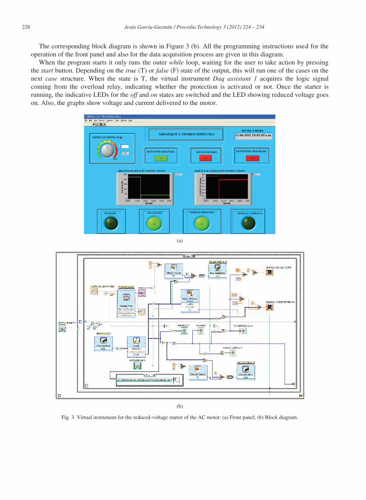
Figure 3 (a) shows the front panel of the main virtual instrument. This is the virtual interactive interface for the user. It allows the preset of the period for reduced voltage operation, using the knob at the top left corner (set at 5 seconds in the shown display). Start and stop buttons are also available in the virtual panel. The user only needs to set the time delay for the switching from reduced voltage to full voltage and then press the start button. The system will show through indicative lights when the starter is on and whether it is working at reduced or full voltage. Instantaneous values of voltage and current of the motor are displayed graphically.
The corresponding block diagram is shown in Figure 3 (b). All the programming instructions used for the operation of the front panel and also for the data acquisition process are given in this diagram.
When the program starts it only runs the outer while loop, waiting for the user to take action by pressing the start button. Depending on the true (T) or false (F) state of the output, this will run one of the cases on the next case structure. When the state is T, the virtual instrument Daq assistant 1 acquires the logic signal coming from the overload relay, indicating whether the protection is activated or not. Once the starter is running, the indicative LEDs for the off and on states are switched and the LED showing reduced voltage goes on. Also, the graphs show voltage and current delivered to the motor.
(a)
(b)
Fig. 3. Virtual instrument for the reduced-voltage starter of the AC motor: (a) Front panel; (b) Block diagram.
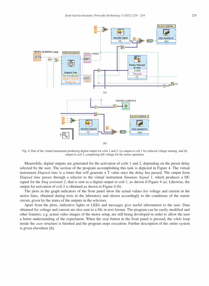
Fig. 4. Part of the virtual instrument producing digital output for coils 1 and 2: (a) output to coil 1 for reduced voltage starting, and (b) output to coil 2, completing full voltage for the motor operation.
Meanwhile, digital outputs are generated for the activation of coils 1 and 2, depending on the preset delay selected by the user. The section of the program accomplishing this task is depicted in Figure 4. The virtual instrument Elapsed time is a timer that will generate a T value once the delay has passed. The output from Elapsed time passes through a selector to the virtual instrument Simulate Signal 1, which produces a DC signal for the Daq assistant 2, that is sent as a digital output to coil 1, as shown if Figure 4 (a). Likewise, the output for activation of coil 2 is obtained as shown in Figure 4 (b).
The plots in the graph indicators of the front panel show the actual values for voltage and current in the motor lines, obtained during tests in the laboratory and shown accordingly to the conditions of the starter circuit, given by the states of the outputs in the selectors.
Apart from the plots, indicative lights or LEDs and messages give useful information to the user. Data obtained for voltage and current are also sent to a file in text format. The program can be easily modified and other features, e.g. actual video images of the motor setup, are still being developed in order to allow the user a better understanding of the experiment. When the stop button in the front panel is pressed, the while loop inside the case structure is finished and the program stops execution. Further description of the entire system is given elsewhere [6].
Fig. 5. Power circuit taking the digital output of the DAQ board and driving current to the coils of the power relays. (a) Schematic diagram; (b) actual implementation.
2.2. Power circuit
Between the control section and the motor, there is a circuit which delivers current to the relays, based on the digital signals produced by the program. The data acquisition board that receives data from the software cannot manage the current required for the operation of the power relays and, therefore, a power circuit is required for driving proper values of current. In the experimental setup, this very simple circuit (Figure 5) was mounted on a breadboard and it was constructed using optocouplers 4N26, relays RAS-0510 for 5 VDC, two NPN transistors TIP 41C. The digital output of the data acquisition board is fed to the optocoupler activating the LED component. The control signal is then received by the phototransistor part of the device and sent to the TIP 41C transistor, where it is amplified. Collector current is send to the RAS-0510 relay driving the coil of the contactor in the motor circuit.
Fig. 6. Schematic diagram showing the connections between the DAQ card and the power circuit.
A 16-bit National Instruments NI USB-6211 DAQ board was used for the data acquisition process. Although it is a basic general-purpose board, it provided enough connectivity for the project. Connections to the DAQ board are shown in Figure 6. A digital input is received from the overload relays, in order to display the corresponding message in the front panel when the protection is activated. Two digital outputs are connected to the inputs of the power circuit described in the previous section. All the input and output ports of the DAQ board are configured via software in the virtual instrumentation.
3. Remote access operation
Remote access through the web was achieved using a LabVIEW® server. It is possible to access the front panel in real time simultaneously from different sites, but only one user at a time can have the control of the panel and the experiment. This is a powerful feature of the system for teaching and training, given that it permits real time demonstrations and exchange of experiences between users, particularly in the engineering field. Remote engineering laboratories have shown benefits since early works dealing with DC motors [7] and collaborative pedagogical approaches [8], up to the most recent developments oriented to remote engineering control systems, such as the Matlab® based 4-quadrant speed control, by Irmak et al. [9], the network of laboratories in Spanish universities described by Vargas et al. [10], and the web laboratory based in LabVIEW® in which Stefanovic et al.[11] emphasize the importance of making the student able to remotely manipulate the actual experiments.
3.1. Configuring the LabVIEW® server
Available within the LabVIEW® software, there is a Web server application that allows uploading of virtual instruments to the Internet (Figure 7 (a)). Besides providing the URL with the IP of the computer running the virtual instruments, the server requires configuration of a group of parameters. First, the Web server option must be enabled. Given that the software developed runs in Windows OS, the default port HTTP 80 was used. This value must be changed to 8000 for Mac OS or Linux. Secondly, Browser Access must be configured for Allow viewing and controlling in order to permit remote users to use the virtual instrument. Finally, the virtual instrument must be added to the Visible VIs list in order to publish it.
(a) (b)
Fig. 7. (a) Configuration of the Web server application within LabVIEW®. (b) The front panel as seen from a web explorer.
A HTML file is required for the setup of the URL that users must access in order to use the virtual instrument. Using the Web publishing tool, and selecting the virtual instrument, the option Request control must be enabled in the mode embedded. Next, the title of the web page, header and footer must be given. All these settings are saved in the HTML file. The URL for the access to the virtual instrument is then obtained.
When the virtual instrument is accessed remotely, it is not necessary to have LabVIEW® installed. However, it is required to install the proper version of the application LabView Run Time Engine. From the front panel in the main computer, i.e. the one where the software is locally installed with the motor setup, control of the virtual instrument can be given to other users. As stated before, several users can view the experiment simultaneously, but only one of them can have the control at a time. Figure 7 (b) shows the front panel as seen from a web explorer.
4. Results and discussion
The system was implemented for the control of the ¼ HP three-phase squirrel-cage induction motor shown in Figure 8 (a). The module of variable resistances, the three-phase Siemens coils and the Siemens overload relays are shown in Figure 8 (b). The software was developed and installed in a laptop computer running Windows and a NI USB-6211 DAQ board was used for data acquisition, as shown in Figure 8 (c).
The system worked as expected both locally and remotely. The virtual instrument for the reduced voltage starting of the motor allowed the control of the transient conditions and it was tested using several delay times for the reduced voltage period. Equipment normally available in the laboratory was used and only a few extra components were required for the power circuit mounted on the breadboard. The system was also tested over the Internet, overcoming difficulties due to limitations imposed in the local area network, firewall and antivirus restrictions.
Once the whole system worked as required, its general features were summarized and extracted in order to create new developments in three laboratories, adding a complete Internet-based system for controlled access of users. Also, a pedagogical study and a poll have been implemented and conducted to find out what students pull off and think about the system. The study aims to compare learning achievements of the virtual environment versus the conventional in-site laboratory approach, in order to determine whether and in which level the proposed system results in pedagogical, financial and logistical benefits.
(a) (b) (c)
Fig. 8. Experimental setup: (a) Squirrel-cage motor; (b) resistances, coils and overload relays; (c) software in laptop computer and DAQ board.
A virtual environment has been developed for remote access to a laboratory experiment. The system permits web-based performing of tests on a squirrel-cage AC motor and complementary hardware implemented in a laboratory for educational use, allowing students to run the experiments from different locations. Thus, the system becomes a useful tool for collaborative coursework, enabling shared use of resources for several schools located along five campuses of the university in which it is implemented.
The system makes use of virtual instrumentation for the monitoring and automation of the tests, as well as for the remote access and for the setup of the web-based experiments. Accessing the system through the Internet permits the shared use of the system within a virtual collaborative environment. On the one hand, teachers can use the system for demonstration of experiments that students can follow via the Internet from different locations. On the other hand, students can gain access to the experiment from different locations, although only one of them can have control of the virtual environment at a time. Collaborative work is also feasible using the developed virtual environment.
Additional features of the system are still under development and it is expected to get much better versions of the program in the near future, as well as a management scheme for the controlled remote access of students to the experiments. Although the target in this report is only the operation of a reduced-voltage starter for an AC motor, the model can be extended to other laboratory experiments for engineering education.
Further work is currently directed towards the development of new web-labs applying the same scheme described in this paper, improving them with the addition of features such as audio and video communication with the actual laboratory, and complementing the learning tasks with other online activities in order to increase the benefits of the web-based experience. Following the outcomes of recent works on the management of web-based laboratory resources in universities [12,13], a web access system is also being designed and implemented, which allows registration and login of users, manages schedule for accessing the experimental setup, and enables communication with the actual environment of the laboratory. Details on this web-access system have been reported separately [14].
Assessment of the virtual environment proposal is still in progress, including several stages. First, the system is being evaluated by a group of students in the campus where the actual laboratory is located. Secondly, tests will be conducted from campuses in other cities where the university offers the same undergraduate courses in engineering. Finally, the system will be tested from campuses of other universities in the country and abroad, through collaborative links previously established. It is expected that feedback obtained will help to improve the overall performance and general characteristics of the developed web-based laboratories.
References
[1] Schaf, F.M., Müller, D., Bruns, F.W., Pereira, C.E. and Erbe, H.H. Collaborative learning and engineering workspaces. Annual
Reviews in Control 2009; 33:246-252.
[2] Tichkiewitch, S., Shpitalni, M., Krause, F.L. Virtual research lab: a new way to do research. CIRP Annals - Manufacturing
Technology 2006; 55-2:769-792.
[3] Mir, M., Sharif, T., Ahmadian, Z. and Hassanpour, A. A web-based remote laboratory for performing experiments in basic
[6] Silva-Del-Rosario, F.H. Control automático de un motor de corriente alterna mediante instrumentación virtual. BEng Thesis
México: Universidad Veracruzana; 2010.
[7] Yeung K. and Huang, J. Development of a remote-access laboratory: a dc motor control experiment. Computers in Industry 2003;
52-3:305-311.
[8] Sivakumar, S.C., Robertson, W., Artimy, M., Aslam, N. A web-based remote interactive laboratory for Internetworking
education. IEEE Trans. on Education, 48-4 (2005) 586-598.
[9] Irmak, E., Bayindir, R., Colak, I. and Soysal, M. A remote laboratory experiment for 4-quadrant control of a DC motor. Computer
Applications in Engineering Education 2011; 19-4:747-758.
[10] Vargas, H., Sanchez, J., Jara, C.A., Candelas, F.A., Torres, F. and Dormido, S. A network of automatic control web-based
laboratories. IEEE Trans. on Learning Technologies 2011; 4-3:197-208.
[11] Stefanovic, M., Cvijetkovic, V., Matijevic, M. and Simic, V. A LabVIEW-based remote laboratory experiments for control
engineering education. Computer Applications in Engineering Education 2011;19-3:538-549.
[12] Wannous, M., Nakano, H., Nagai, T. Google Calendar™ for managing and monitoring the utilization of a web-based laboratory’s resources. IEEE Global Engineering Education Conference (EDUCON) 2011; 210-213.
[13] Bo, L. Design and implementation of Web-based laboratory management system in colleges and universities. 3rd International
Conference on Computer Research and Development (ICCRD) 2011; 2:468-471.