48
Virtual Environments: System Architectures Anthony Steed Simon Julier Department of Computer Science University College London http://www.cs.ucl.ac.uk/teaching/VE
Virtual Environments: System Architectures
Anthony SteedSimon JulierDepartment of Computer ScienceUniversity College London
http://www.cs.ucl.ac.uk/teaching/VE

Outline
• Problem Statement
• Representing the Environment
• User dynamics
• Execution Models

Problem Statement
• Problem Statement
• Representing the Environment
• User dynamics
• Execution Models

Reminder - VE is an Immersive,Mediated Communication Medium
User
Interface Devices
Environment
User
Synthetic Environment
Real Environment
Mediated Medium

Key Requirements of Systems
• Speed of update– Especially in rendering and haptics
• Latency– Time from tracker update to display change should be as short as
possible (ideally <75ms)
• Consistency– Environment state should be consistent with input
• Expressivenees– Environment should respond to a range of user input

Modules and ResponsibilitiesGraphics
Rendering
AudioRendering
HapticRendering
HapticScene-Graph
Network
MasterEnvironment
Input Devices
ExternalDatabases Graphics
Scene-Graph
InteractionProcessing
AudioScene-Graph

Different Display Modes Have Different Requirements
• Video (N copies – for stereo and multiple screens)– Maintain copy of visual state– Render as fast as possible (~60Hz)– Synchronise with other renders
• Audio– Maintain copy of audio state– Render without glitches (requires fast interrupt)
• Haptics– Maintain copy of haptic data
Render as fast as possible (~1000Hz)

Representing the Environment
• Problem Statement
• Representing the Environment
• Dynamics
• Execution Models

Environment
• Environment is a broad term, but what is it we are actually modelling?– Something that can be rendered and interacted with such
that• We utilize capabilities of display system• Maximize the opportunity for interaction
• Ellis states that VEs have 3 main components:– Content– Geometry– Dynamics
Contents
• Environment is made up of discrete items known as objects and actors
• Objects– Discrete and identifiable – Described by property vectors
• Actors are objects that initiate interactions• The self is a special kind of actor with a point-of-view

Representing the Contents
• Unfortunately little agreement about conventions, schema, specifications for describing environments– Relates to issues about defining and using ontologies– Standards where they exist usually focus on visual
representation– Possibility that some standards will emerge
• Well-known example is the Distributed Interactive Simulation (DIS) Entity Model

Motivation for DIS(SIMNET)• Born out of needs for large-
scale military simulations:– Hundreds of different types of
entities– Dozens of servers scattered
throughout the world– Real-time– Man-in-the-loop
• Complicated environments• Complicated interactions

DIS Environmental Model
• World modelled as a set of entities– All entity locations available to all entities– All entities can serve as actors– All interactions between entities via events– Networking achieved using a mix of approaches:
• Ground truth information• State change information• Dead reckoning
• Entities and events are described by their Protocol Data Units (PDUs)
To be discussed in Week ~11}

Representing Entities with DIS
IEEE Standards 1278.1-1995 & 1278.1a-1998

Representing the Environment with DIS
• Environments are considered to be object states which aren’t associated with a specific entity
• Environmental states can come in several flavours:– Gridded data (e.g., terrain)– Point objects (e.g., trees)– Linear objects (e.g., roads)– Area objects (e.g., bogs)

Geometry
• Description of the environmental field of action• Contains:
– Dimensionality: The degree of freedom of the position vector– Metric: The basic mathematical rules for defining order,
distance, etc.– Extent: The range of possible values of the position vector
• Defines the “space” where the environment is described

Describing Environment Geometry
• Typically Euclidean– simple (x, y, z); suitable for many applications
• However not that straight forward– Euclidean not that useful for describing geometry on
spheroids (e.g. planets)• Use a locally linear model (i.e. on a tangent plane)
– Not terribly useful in large-scale collaborative environments (everyone wants to be at (0,0,0))
• Use a differential geometry model (i.e. everyone sets their own coordinates and connections between models have relative transforms)

Describing Object Geometry
• Objects need to have a description in physical space• Implicit or assumed to be 3D Cartesian coordinates with a 1m
unit scale usually• Described in two steps:
– Describe the basic form of the environment • 3D models, usually polygonal, there are standards for this (VRML, DXF, OBJ)
– Add properties to objects• Visual properties: colour, texture, shading, …• Sound properties: sources, reflectivity, …• Material properties: weight, elasticity, …• Semantic properties: (name, role, age, …)• No standards for this
• Often implemented using a scene-graph

Graphs
• A graph consists of vertices and edges
• Vertices define the “state”information
• Edges define “relationships”
• Scene-graphs are directed and acyclic
Arbitrary graph
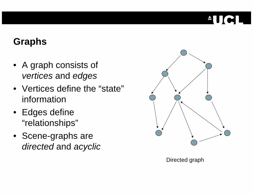
Graphs
• A graph consists of vertices and edges
• Vertices define the “state”information
• Edges define “relationships”
• Scene-graphs are directed and acyclic
Directed graph

Graphs
• A graph consists of vertices and edges
• Vertices define the “state”information
• Edges define “relationships”
• Scene-graphs are directed and acyclic
Directed acyclic graph

Graphs
• A graph consists of vertices and edges
• Vertices define the “state”information
• Edges define “relationships”
• Scene-graphs are directed and acyclic
Arbitrary graphDirected graphDirected acyclic graph

Scene-graphs
• In a scene-graph, vertices are often called nodes– Store state information– Can include arbitrary property
information• All graphs have a root node
which defines the base of the tree
• All other nodes divided into two types:– Group nodes– Leaf Nodes
Root node
Group nodes
Leaf nodes

Group Nodes
• Group nodes have multiple nodes as children– Child nodes can be other group nodes or leaf nodes
• Applies common state information to multiple objects– State information propagates down the graph
• Examples include:– Transformations– Switch nodes– Effects
• Bump mapping, scribing, specular highlights

Examples (OpenSceneGraph)
Anisotropic Lighting
ScribingCartoon
Bumpmapping

Leaf Nodes
• Leaf nodes cannot have children• State information relates to the appearance of specific
objects• Examples include:
– Geometry– Image based rendering
• Billboards• Impostors
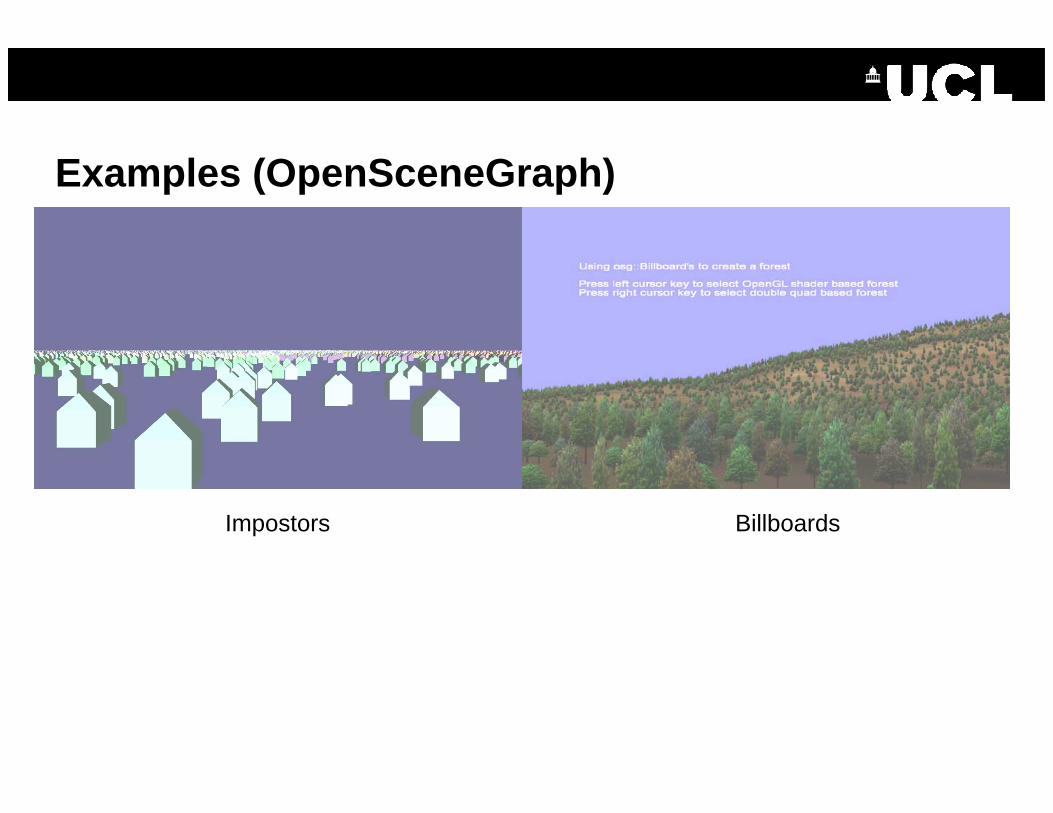
Examples (OpenSceneGraph)
Impostors Billboards

Dynamics
• These are the rules of interaction between the contents
• These can be:– Differential equations of Newtonian dynamics to describe
kinematic and dynamic relationships– Grammatical rules for pattern-matched triggered actions
• Many different ways of doing this from imposing numerical approximations to Newtonian physics, through to plain old C++ / Java / XVR coding
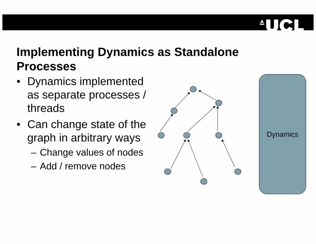
Implementing Dynamics as Standalone Processes• Dynamics implemented
as separate processes / threads
• Can change state of the graph in arbitrary ways– Change values of nodes– Add / remove nodes
Dynamics

Implementing Dynamics Within the Scene-Graph
• Fairly “autonomous”dynamics can be achieved by embedding dynamics within the scenegraph
• Animations are group nodes which apply state changes to their children
• Examples include:– Animation paths– Particle systems
Animation Node
Animated nodes

Example Animation and Particle System

Generalised Dynamics: Application Nodes
• Pre-defined behaviours allow lots of effects but are autonomous– Script nodes (e.g., in VRML) can be used to generalise behaviour
• Most extreme example are application nodes:– Entire VR application is written as a group node in the scenegraph– Application contains certain resources (e.g., viewport to display graphics)– Application owns and manages all of the nodes beneath it– Unifies application and environment state
• Capabilities include:– Multiple applications in same environment– Load balancing– Dynamic workgroup management

User Dynamics
• Problem Statement
• Representing the Environment
• User dynamics
• Execution Models
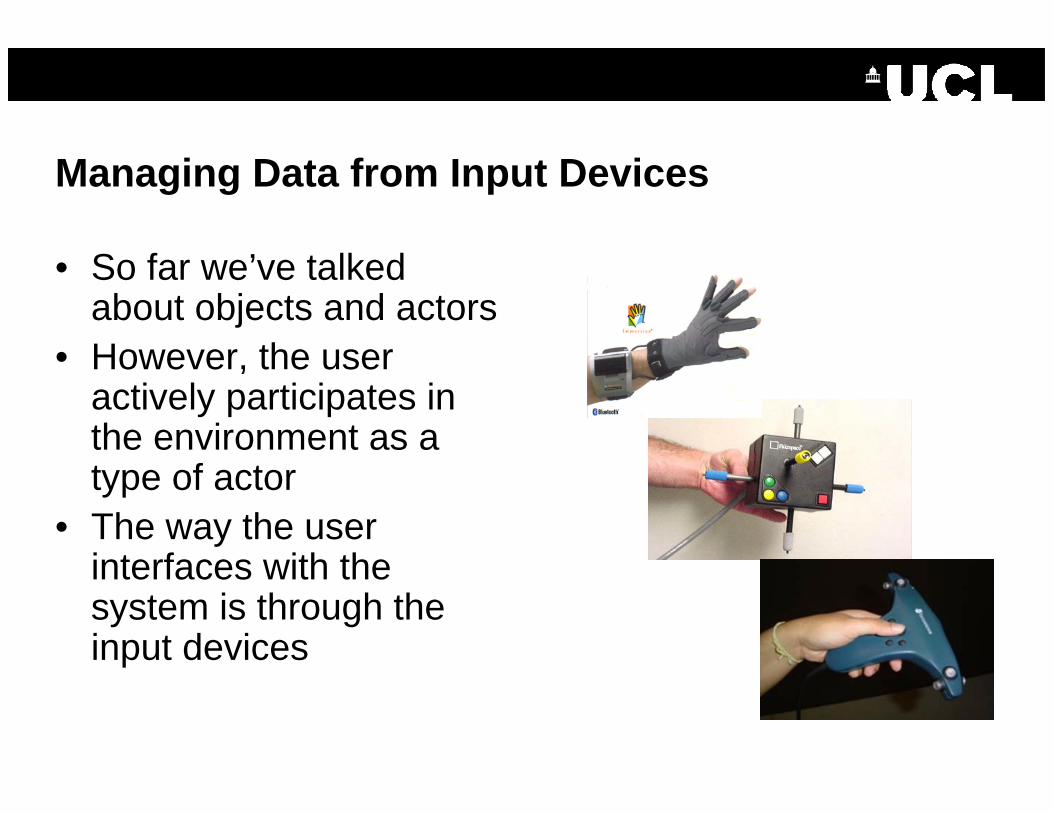
Managing Data from Input Devices
• So far we’ve talked about objects and actors
• However, the user actively participates in the environment as a type of actor
• The way the user interfaces with the system is through the input devices

Complexity of Input Devices
• VR systems present unique challenges to the design of user interfaces:– 6 degrees of freedom– Many types of interactions– Lots of different configurations of devices available– No agreed standards on what is the “right way” to navigate /
interact with the environment• One means of capturing the flexibility is to use a
dataflow model

Data Flow Model
• Processing consists of a series of filters• Each filter has multiple input ports and a single output port• Outputs from one filter can be treated as inputs to other filters• Information sources are raw source of information (e.g.,
devices)• Information sinks are final destination (e.g., applications)
Source 1
Filter
Source 2
Port 1
Port 2
Output
Filter Sink
Source 3
OpenTracker

Example Hybrid System
• Combines 2D tracker (blue) with 3D vision-based tracker (black square is fiducial marker)

Execution Models
• Problem Statement
• Representing the Environment
• User dynamics
• Execution Models

Execution Model Ties Everything Together
• So far we we’ve talked about a disparate set of systems:– A master environment– Separate representations for different output modes– User interfaces for controlling the environment
• The execution model “glues” all these parts together– Closely related to distributed systems as well

Execution Models Tying Things Together
• Example:– The position on an object is changed– The update needs to be reflected in:
• The master database• The different scenegraphs• Over the network (if connected)
– How can all of this be coordinated?• Two main models:
– Kernel model– Actor/object model (events)

Simplified Kernel Model
• Treats a VR application like a traditional graphical application:
• In practice, it’s never as simple as this…
while(true){
read_trackers();
set_body_position();do_animation();
render_left_eye();render_right_eye();render_sound();
poll_trackers();
}

Kernel: Application Runtime
App: Frame FunctionsDraw Manager
App: Initialization
Gadgeteer: Device UpdateKernel: System Reconfig
Kernel Model for VRJuggler

Pros / Cons of the Kernel Model
• Advantages:– Simple to understand– Application programmer keeps their own data structures (no need for a
scene-graph)
• Disadvantages:– Implementation needs care because of different update rates– Usually requires some awareness of parallel programming issues– Lots of complexity ends up in the do_animation()method
• XVR addresses some of these issues through its threading / event model

XVR Threading Model

Actor Model• Virtual environment is
realised by a set of collaborating asynchronous processes (actors)
• Actors send messages to one another
• Processes share a common database
• Database typically organised around a scene-graph
DatabaseAudio
Video1
Video2
TrackingSpeech
Collision
Application

Setting Object State Using in the Actor Model
• Setting the object state is often achieved using thesubject-observer design pattern
• The object in the database is the subject• Different renderers / networking systems are the
observers• When the subject’s state is updated, the observers are
automatically notified

Pros / Cons of the Actor Model
• Advantages:– Application program does not care about distribution / what
rendering systems used– Update rates and parallel processing issues handled by
mutexes and buffering event objects– Complex chains of events can be implemented
• Disadvantages:– Difficult to understand– Difficult to code– Can lead to strange cyclic dependency effects

Summary
• Representing the environment is difficult– The representation has to be rich enough to capture the contents,
geometry and dynamics– Each display mode requires its own form of the environment to optimise
the display
• Want to make content as rich as possible to support dynamic models– Otherwise behaviour is expressed only in code.
• At run-time there are logically concurrent processes (rendering, collision, audio etc…)
• Execution models need to reflect this concurrency


