+ All Categories
Home > Documents > Virtual Laboratories for Reinforced Concreteconcrete/java/papers/... · Virtual Laboratories for...

Virtual Laboratories for Reinforced Concreteconcrete/java/papers/... · Virtual Laboratories for...

Date post: 27-Apr-2018
Category:
Upload: buidan
View: 220 times
Download: 2 times
Share this document with a friend
26
1 WWW-Based Virtual Laboratories for Reinforced Concrete Education 1 HUA JIANG Graduate Assistant, Civil Engineering and Geological Sciences, University of Notre Dame, Notre Dame, Indiana YAHYA C. KURAMA Assistant Professor, Civil Engineering and Geological Sciences, University of Notre Dame, Notre Dame, Indiana DAVID A. FANELLA Manager, Buildings and Special Structures, Portland Cement Association, Skokie, Illinois ABSTRACT: This paper introduces three interactive virtual laboratory modules for undergraduate and graduate level education on the behavior and design of reinforced concrete structures using the World Wide Web (WWW). Users can select and configure module parameters (such as reinforcement) to investigate the design and behavior of a reinforced concrete member or section. Keywords: interactive, Java, reinforced concrete, virtual laboratory, World Wide Web INTRODUCTION This paper describes the development and use of three WWW-based interactive virtual laboratory modules for undergraduate and graduate level education on the analysis, behavior, and design of reinforced concrete (RC) structures. Recent studies show that engineering students can be educated most effectively through examples and experiments (i.e., experiential learning) [1]. Conventional methods of conducting examples are based on analytical methods and/or laboratory tests. However, limitations on time and other resources (e.g., space and financial resources) often restrict the number of examples and what-if studies that can be covered in class, in the laboratory, or as homework assignments. It may be possible to overcome some of these limitations by using the WWW as a means to develop interactive educational tools geared towards experiential learning. The rapid growth of the WWW has provided educators with unprecedented flexibility in recent years [2-5]. As described by Wallace and Weiner [6], WWW-based instructional materials 1 © Wiley Periodicals, Inc. Computer Applications in Engineering Education 10: 1-16, 2002
Transcript

1

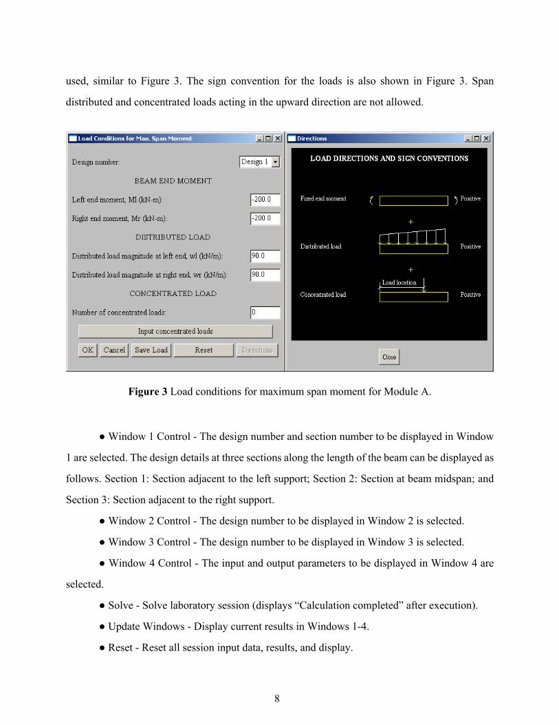
WWW-Based Virtual Laboratories for Reinforced Concrete Education1

HUA JIANG Graduate Assistant, Civil Engineering and Geological Sciences, University of Notre Dame, Notre Dame, Indiana YAHYA C. KURAMA Assistant Professor, Civil Engineering and Geological Sciences, University of Notre Dame, Notre Dame, Indiana DAVID A. FANELLA Manager, Buildings and Special Structures, Portland Cement Association, Skokie, Illinois

ABSTRACT: This paper introduces three interactive virtual laboratory modules for

undergraduate and graduate level education on the behavior and design of reinforced concrete

structures using the World Wide Web (WWW). Users can select and configure module parameters

(such as reinforcement) to investigate the design and behavior of a reinforced concrete member or

section.

Keywords: interactive, Java, reinforced concrete, virtual laboratory, World Wide Web

INTRODUCTION

This paper describes the development and use of three WWW-based interactive virtual laboratory

modules for undergraduate and graduate level education on the analysis, behavior, and design of

reinforced concrete (RC) structures. Recent studies show that engineering students can be

educated most effectively through examples and experiments (i.e., experiential learning) [1].

Conventional methods of conducting examples are based on analytical methods and/or laboratory

tests. However, limitations on time and other resources (e.g., space and financial resources) often

restrict the number of examples and what-if studies that can be covered in class, in the laboratory,

or as homework assignments. It may be possible to overcome some of these limitations by using

the WWW as a means to develop interactive educational tools geared towards experiential

learning.

The rapid growth of the WWW has provided educators with unprecedented flexibility in

recent years [2-5]. As described by Wallace and Weiner [6], WWW-based instructional materials 1 © Wiley Periodicals, Inc. Computer Applications in Engineering Education 10: 1-16, 2002

2

have a wide range of sophistication and intended use, varying from course administration, lecture,

and assignment tools, to laboratory simulation and experiment platforms. While the use of these

materials in engineering education is increasing at a fast rate, most of the instructional courseware

that can be found on the WWW is completely “static” and “non-interactive”, offering little

advantage over conventional methods in experiential learning. Recent advances in technology

demand a more significant evolution in education, which is the main motivation for the

development of the virtual laboratories described herein.

One of the most exciting recent developments for engineering education is the availability

of computer programs, referred to as Java™ applets, specifically designed for the WWW. This

paper uses these advancements to achieve four specific objectives: (1) to develop effective and

modern educational tools in order to overcome some of the limitations of conventional teaching

methods in experiential learning; (2) to develop interactive tools that allow the students to

investigate the subject matter at their own pace and in the order that they choose, rather than follow

a limited number of examples selected and designed by the instructor; (3) to use these tools to

demonstrate fundamental concepts on the analysis, behavior, and design of RC structures; and (4)

to stimulate the students’ interest, creativity, and thinking, and thus, encourage them to pursue

higher degrees.

The virtual laboratory modules described in the paper address the following topics in

structural engineering: (1) flexural design of RC beams; (2) axial-force-moment-curvature

relationships for RC sections; and (3) uniaxial stress-strain relationships for confined and

unconfined concrete. Users can configure the system parameters (e.g., geometry, reinforcement,

concrete confinement, material properties, loading) in each module and observe the effects of

these parameters on the behavior and design of a RC member or section. These capabilities allow

the users to interactively design and conduct their own examples, what-if studies, and experiments

on the Web.

An overview of the modules and their interactive capabilities are described below. A brief

background on Java applets, which form the core computational algorithm for the modules, is also

given. Structural engineering students, educators, and practicing engineers can utilize the modules

freely by accessing the URL at http://www.nd.edu/~concrete/java. The paper includes three

3

introductory sample laboratory sessions to facilitate the use of the modules by interested

individuals.

BACKGROUND

This section provides a brief overview regarding the use of Java applets on the development of the

virtual laboratory modules. The results of a literature survey on other Java-based educational

resources are also discussed.

Java Applets

As stated above, Java applets are computer programs that have been specifically engineered for the

WWW [7, 8]. Users download the applets through a Java-enabled browser such as Netscape™ or

Microsoft Explorer™, and then run the applets on their computer. Java provides significant

advantages for the development of educational software using the Internet, including [9]:

1) One of the most important features of Java applets is that they are completely browser

and platform (i.e., computer hardware and operating system) independent. In other words, a Java

applet can run as well on a PC or MacintoshTM as it does on a SunTM, IBMTM, or Hewlett-

PackardTM workstation.

2) Once downloaded, the running speed of a Java applet is governed by the speed of the

user’s computer. Thus, the performance of an applet on the user’s computer does not depend on the

network connections.

3) Java applets are full-featured, fully-interactive, and easily-maintainable computer

programs, which make them extremely versatile for use in engineering education. The fact that

they are full-featured computer programs means that complex engineering procedures can be

coded using them.

4) Java is interactive. Once an applet is downloaded, the user has full control over the

executable and can utilize its full capabilities on his/her own computer to conduct virtual

experiments and what-if studies. Java applets can display graphics (still or animated), play audio

or video files, and receive user input from a mouse and keyboard.

4

More information on Java is available over the Internet [10]. There are specially designed

utility software packages that can be used in the development of Java applets. These software

packages are readily available from many sources, including free software that can be downloaded

from the Internet [10].

Other Java-Based Laboratory Modules

An extensive review of the WWW and the published media indicate that Java-based interactive

courseware in the area of RC structures, other than the modules described in this paper, is not

available over the Internet. Java-based virtual laboratories that focus on other areas of engineering

do exist (e.g., Earthquake Engineering [11], Electrical Engineering [12], Industrial Engineering

[13], Computational Science and Engineering [14]). However, an overview of these laboratories is

not within the scope of this paper.

Today, Java applets are widely used on the WWW but, in spite of their potential, they are

not utilized much for education purposes. Java has given the Web the power of continuous,

interactive, real-time, visual, and aural instruction. The laboratory modules that are described

below aim to utilize this power in engineering education on RC structures.

DESCRIPTION OF THE LABORATORY MODULES

This section describes three new WWW-based laboratory modules on the analysis, behavior, and

design of RC structures. The verification of the modules is also discussed.

Flexural Design of RC Beams

This virtual laboratory module, referred to as Module A, allows the users to investigate the flexural

design of rectangular RC beams with various support and span loading conditions. The beams are

designed as singly-reinforced prismatic members (i.e., the compression reinforcement is ignored

in the design) with straight reinforcing bars. The design is conducted in accordance with ACI-318

Building Code Requirements for Structural Concrete and Commentary published by the American

Concrete Institute [15].

5

The module follows general design procedures that can be found in any undergraduate

level textbook on RC (e.g., Nilson [16]). Thus, these procedures are not described herein. Up to

five designs can be conducted during a laboratory session to allow for parametric exercises. As

shown in Figure 1, the module-user interface consists of four windows and a control panel. The

four windows display the results from the laboratory session as follows:

Window 1 displays the design details at selected sections along the length of the beam,

including section dimensions, amount of reinforcement, and placement of reinforcement. As an

example, Figure 1 shows the details at Section 1 (section adjacent to the left support) from a

sample laboratory session referred to as Laboratory Session A. More information on this session is

given later.

Figure 1 User interface for Module A.

6

Window 2 displays the design details along the length of the beam, including the amount,

placement, and beginning and end points (i.e., cut-off locations) of the reinforcement. In Figure 1,

the details for Design 1 from Laboratory Session A are shown.

Window 3 shows comparisons between the design flexural capacity (after the application

of a capacity reduction factor, φ=0.90) and the factored design flexural demand along the length of

the beam for positive and negative bending. In Figure 1, the capacity-demand comparisons for

Design 1 are shown.

Finally, Window 4 plots user-selected design output parameters as functions of input

parameters to allow for a comparative investigation and evaluation of the results. As an example,

Figure 1 shows the variation in the area of the bottom steel reinforcement at Sections 1-3 as a

function of the maximum positive factored moment demand along the length of the beam for three

different designs conducted in Laboratory Session A. These three parametric design examples are

described in more detail later.

The control panel for Module A includes the following information:

● Number of Designs - Up to five designs may be conducted during a laboratory session.

● Design Control Option - One of two design control options may be selected for the

session as follows. Option 1: Design using known cross-section height, h, and height-to-width

ratio, h/b; or Option 2: Design using known reinforcement ratio, ρ, and cross-section height-to-

width ratio, h/b.

● Units - English or metric units may be selected. The units may be changed at any time

during the session.

● Design Data - Required design data is specified based on the design control option

selected above. The required data for Control Option 1 (i.e., known cross-section dimensions) and

Control Option 2 (i.e., known reinforcement ratio) are shown in Figure 2. The small rectangular

boxes in Figure 2 indicate areas for user input. The module displays error messages for invalid user

input (e.g., negative h) and warning messages for user input that does not conform to the ACI-318

[15] provisions.

7

(a) (b)

Figure 2 Design data for Module A: (a) control option 1; (b) control option 2.

● Load Conditions for Maximum Span Moment - These load conditions are used to specify

the factored beam moment demand (along the beam length) corresponding to the maximum

moment within the span. A combination of factored design beam end moments, span distributed

loads, and span concentrated loads may be used, as shown in Figure 3. The sign convention for the

loads is also shown in Figure 3. Beam span distributed and concentrated loads acting in the upward

direction are not allowed.

● Load Conditions for Maximum Support Moment - In order to allow for the consideration

of pattern loading in design, a different set of loads may be used to specify the factored beam

moment demand corresponding to the maximum moments at the supports. A combination of

factored design beam end moments, span distributed loads, and span concentrated loads may be

8

used, similar to Figure 3. The sign convention for the loads is also shown in Figure 3. Span

distributed and concentrated loads acting in the upward direction are not allowed.

Figure 3 Load conditions for maximum span moment for Module A.

● Window 1 Control - The design number and section number to be displayed in Window

1 are selected. The design details at three sections along the length of the beam can be displayed as

follows. Section 1: Section adjacent to the left support; Section 2: Section at beam midspan; and

Section 3: Section adjacent to the right support.

● Window 2 Control - The design number to be displayed in Window 2 is selected.

● Window 3 Control - The design number to be displayed in Window 3 is selected.

● Window 4 Control - The input and output parameters to be displayed in Window 4 are

selected.

● Solve - Solve laboratory session (displays “Calculation completed” after execution).

● Update Windows - Display current results in Windows 1-4.

● Reset - Reset all session input data, results, and display.

9

● Zoom - Zoom Windows 1-4.

● Help - Display module help and background information (currently under development).

Axial-Force-Moment-Curvature Relationships for RC Sections

This virtual laboratory module, referred to as Module B, allows the users to investigate the

nonlinear axial-force-moment-curvature relationships for rectangular RC beam-column cross-

sections. The module determines the expected behavior of a user-defined cross-section by first

dividing the section into a number of parallel concrete and steel “fibers”. Then, the section forces

and deformations are determined from the fiber strains and stresses using fundamental principles

of equilibrium, strain compatibility, and constitutive relationships assuming that plane sections

remain plane. A total of fifty fibers are used to model the concrete in compression.

More detailed information on the procedure used to develop the axial-force-moment-

curvature relationship of a cross-section can be found in most undergraduate/graduate level

textbooks on RC structures (e.g., Nilson [16]). Up to five cross-sections can be analyzed during a

laboratory session to allow for parametric exercises. Figure 4 shows the module-user interface,

which consists of four windows and a control panel similar to Module A above. The four windows

display the results from the laboratory session as follows:

Window 1 displays some of the user-defined properties of the cross-sections investigated

in the session. The cross-section dimensions, material properties, amount of reinforcement, and

placement of reinforcement are shown. As an example, Figure 4 shows the properties of Section 1

from a sample laboratory session, referred to as Laboratory Session B. More information on this

session is given later.

Window 2 displays the estimated nonlinear bending-moment-curvature relationships for

the cross-sections investigated in the session. The bending moment is assumed to act such that the

top of the cross-section is in compression. In Figure 4, the moment-curvature relationships for

Section 1 from Laboratory Session B are shown for three user-specified axial force values, P1-P3.

The last point on each curve represents the ultimate curvature (curvature at crushing of the

concrete in the extreme fiber).

10

Figure 4 User interface for Module B.

Window 3 shows the estimated axial-force-bending-moment (P-M) interaction diagrams

corresponding to user-specified strain conditions for the cross-sections investigated in the session.

In Figure 4, the interaction diagrams corresponding to a maximum concrete compression strain of

εc=0.003 are shown for three different cross-sections, S1-S3, from Laboratory Session B. These

cross-sections are described in more detail later.

Finally, Window 4 plots user-selected analysis output parameters as functions of input

parameters to allow for a comparative investigation and evaluation of the results. As an example,

Figure 4 shows the estimated variation in the ultimate curvature (i.e., curvature at crushing of

concrete) as a function of the applied axial forces for the three cross-sections analyzed in

Laboratory Session B.

The control panel for Module B includes the following information:

● Number of Sections - Up to five cross-sections may be investigated during a laboratory

session.

11

● Units - English or metric units may be selected. The units may be changed at any time

during the session.

● Section Properties - The properties of the cross-sections to be investigated in the session

are specified. As shown in Figure 5, the section properties that need to be defined by the user

include the material properties for concrete and reinforcing steel, cross-section dimensions, and

reinforcement amount and location. The concrete is assumed to be unconfined. The compressive

stress-strain relationship of the unconfined concrete is determined using a model described in

Mander et al. [17]. The tensile strength of concrete is assumed to be equal to 'cf7.5 .The module

displays error messages for invalid user input (e.g., negative h) and warning messages for user

input that does not conform to the ACI-318 [15] provisions.

Figure 5 Section properties for Module B.

12

● Axial Forces - Up to five compressive axial forces may be specified to generate moment-

curvature relationships for each cross-section. One of the following three formats may be selected

to input the axial forces for each section: (1) percentage of the balanced axial force, Pb; (2)

percentage of the axial force capacity under concentric loading, Po; and (3) numeric values of the

axial forces.

● Strain Condition for P-M Interaction - The P-M interaction diagrams in Window 3

correspond to a user-specified maximum concrete strain in each cross-section. A strain value less

than or equal to the concrete crushing strain may be used.

● Window 1 Control - The cross-section number to be displayed in Window 1 is selected.

● Window 2 Control - The cross-section number to be displayed in Window 2 is selected.

● Window 3 Control - The cross-section number(s) to be displayed in Window 3 are

selected.

● Window 4 Control - The cross-section number(s) as well as analysis input and output

parameters to be displayed in Window 4 are selected.

● Solve - Solve laboratory session (displays “Calculation completed” after execution).

● Update Windows - Display current results in Windows 1-4.

● Reset - Reset all session input data, results, and display.

● Zoom - Zoom Windows 1-4.

● Help - Display module help and background information (currently under development).

Uniaxial Stress-Strain Relationships for Confined and Unconfined Concrete

This virtual laboratory module, referred to as Module C, allows the users to investigate the effect

of lateral confinement on the uniaxial compressive stress-strain relationship of concrete, including

the effect of confinement on concrete ductility and strength. Concrete confinement in the form of

steel ties, hoops, or spirals is usually needed to increase the ductility of concrete in seismic regions.

A number of confinement models are available in the literature to estimate the compressive

stress-strain behavior of concrete (e.g., Mander et al. [17], Kent and Park [18], Sheikh and

Uzumeri [19]). The model developed by Mander et al. [17] is used in Module C.

13

Detailed information on the compressive stress-strain behavior of confined concrete can be

found in many graduate-level textbooks, particularly in textbooks that focus on the seismic

behavior and design of RC structures (e.g., Paulay and Priestley [20]). Thus, this topic is not

discussed further in this paper. Up to five concrete specimens can be investigated during a

laboratory session to allow for parametric exercises. Figure 6 shows the module-user interface,

which consists of four windows and a control panel similar to Modules A and B above. The four

windows display the results from the laboratory session as follows:

Figure 6 User interface for Module C.

Window 1 shows the user-defined properties of the concrete specimens investigated in the

session. The material properties and amount of reinforcement are displayed. As an example,

Figure 6 shows the properties of Specimen 3 from a sample laboratory session referred to as

Laboratory Session C. More information on this session is given later.

Window 2 displays the estimated stress-strain relationships for the concrete specimens

investigated in the session. In Figure 6, the stress-strain relationships for three specimens, S1-S3,

from Laboratory Session C are shown. More information on these specimens is given later.

14

Windows 3 and 4 are used to plot user-selected analysis output parameters as functions of

input parameters to allow for a comparative investigation and evaluation of the results. As an

example, Windows 3 and 4 in Figure 6 show the estimated variation in the concrete strength and

ultimate strain (i.e., strain at crushing of concrete), respectively, as a function of the confining steel

ratio, ρ (defined as the ratio of the volume of lateral confining steel to the volume of confined

concrete core [17]), for the three specimens analyzed in Laboratory Session C.

The control panel for Module C includes the following information:

● Number of Specimens - Up to five concrete specimens may be investigated during a

laboratory session.

● Units - English or metric units may be selected. The units may be changed at any time

during the session.

● Specimen Type - Currently, only circular specimens can be investigated by the module.

Rectangular specimens will be included in the future.

● Specimen Properties - The properties of the specimens to be investigated in the session

are specified. As shown in Figure 7, the specimen properties that need to be defined by the user

include the material properties for concrete and steel, and the amount of reinforcement. The

module displays error messages for invalid user input (e.g., negative s) and warning messages for

user input that does not conform to the ACI-318 [15] provisions.

● Window 1 Control - The specimen number to be displayed in Window 1 is selected.

● Window 2 Control - The analysis output parameters, stress and strain, to be displayed in

Window 2 are specified.

● Window 3 Control - The analysis input and output parameters to be displayed in Window

3 are selected.

● Window 4 Control - The analysis input and output parameters to be displayed in Window

4 are selected.

● Solve - Solve laboratory session (displays “Calculation completed” after execution).

● Update Windows - Display current results in Windows 1-4.

● Reset - Reset all session input data, results, and display.

15

● Zoom - Zoom Windows 1-4.

● Help - Display module help and background information (currently under development).

Figure 7 Specimen properties for Module C.

Verification of the Modules

This section describes the verification of the laboratory modules. Module A was verified by

comparing the results with designs from manual calculations as well as from a widely-available RC

beam design software package, PCABEAM [21], developed by the Portland Cement Association

(PCA). Similarly, Module B was verified based on manual calculations and comparisons with a

structural analysis software, DRAIN-2DX [22]. The fiber beam-column element in DRAIN-2DX

[22] was used for this purpose. Finally, Module C was verified by comparing the results with

manual calculations based on the procedure described by Mander et al. [17].

16

In order to minimize the number of errors in the modules, the computational algorithms

were first coded and verified using the MatlabTM Program [23]. Then, the Matlab codes were

converted into Java codes. A large number of verification analyses and designs were conducted to

identify and correct any errors in the modules. However, it is recognized that like any software,

unidentified errors may still exist.

USE OF THE LABORATORY MODULES

The WWW laboratories described in this paper may be utilized for a variety of purposes in

structural engineering. Firstly, the modules can be used as tools to supplement classroom, home,

and laboratory exercises and assignments in undergraduate and graduate level RC design and

analysis courses. Three courses offered at the University of Notre Dame use the modules: (1)

CE486-Reinforced Concrete Design (senior level); (2) CE598E-Advanced Behavior and Design

of Concrete Structures (graduate level); and (3) CE598G-Earthquake Engineering (graduate

level).

Flexural design of RC beams is one of the fundamental topics covered in undergraduate

curricula, and thus, Module A would be suitable for use in undergraduate level courses on RC

design. Moment-axial-force interaction diagrams are usually covered in undergraduate curricula,

while nonlinear moment-curvature relationships may be more suitable for graduate level students.

Thus, Module B can be used in both undergraduate and graduate level courses. Finally, Module C

may be more suitable in graduate courses on the seismic behavior and design of RC structures.

Secondly, the modules may be used by practicing engineers to carry out routine design

calculations and checks. Clearly, the complete design and analysis of a RC structure cannot be

conducted using these modules. However, some engineers may find it convenient and attractive to

complete or verify isolated components of the design or analysis over the Internet. Furthermore, it

may be possible to develop more sophisticated and comprehensive design and analysis modules in

the future.

Finally, the modules may provide new opportunities for distance education, outreach

activities, and education of local communities. Because of their free and instant availability and

accessibility over the Internet, the modules can be used to give demonstrations as part of a distance

17

education/outreach program. Java applets provide an excellent means for these applications, since

they are platform independent and their performance is not affected by network connections.

In order to facilitate the use of the modules by interested individuals, three introductory

sample laboratory sessions, Sessions A, B, and C, are described below. In general, any valid

user-specified data can be selected to conduct a parametric investigation using the modules.

However, because of limited space, only a limited number of design and analysis parameters are

demonstrated in the sample sessions below. As part of a design/analysis course, it is recommended

that the students are asked to first conduct similar sample sessions and verify the results based on

manual calculations. Then, the students can select and conduct their own parametric

investigations, possibly within a set of guidelines provided by the instructor.

Sample Laboratory Session A

This sample laboratory session demonstrates the use of Module A on the flexural design of

rectangular RC beams. A parametric investigation is carried out with three different designs using

Design Option 1 (i.e., known cross-section dimensions). The three designs are conducted for

increasing amounts of loading as shown in Figure 8. Table 1 summarizes the data input for the

session. The values in italics show the data that are varied between the different designs.

200kN-m

200kN-m

90 kN/m

7.5 m

300kN-m

300kN-m

70 kN/m

7.5 m

300kN-m

300kN-m

110 kN/m

7.5 m

400kN-m

400kN-m

90 kN/m

7.5 m

110 kN/m

400kN-m

400kN-m

130 kN/m

7.5 m

500kN-m

500kN-m

7.5 m

Design 1 Design 2 Design 3

Load conditions for max. span moment

Load conditionsfor max. support moment

Figure 8 Load conditions for Sample Laboratory Session A.

18

Table 1 Sample Laboratory Session A

Session Input Design 1 Design 2 Design 3 Design control option Known h, h/b Concrete compressive strength, fc' (MPa) 27.5 27.5 27.5 Steel yield strength, fy (MPa) 400 400 400 Beam length, l (m) 7.5 7.5 7.5 Section height, h (cm) 60 60 60 Section height/width, h/b 1.75 1.75 1.75 Minimum bar size number 19 19 19 Maximum bar size number 25 25 25 Vertical clear cover, cv (cm) 4 4 4 Side clear cover, cs (cm) 4 4 4 Minimum clear bar spacing, sb (cm) 3 3 3 Stirrup diameter, ds (cm) 0.95 (No. 10) 0.95 (No. 10) 0.95 (No. 10) Max. cut-off ratio of span reinforcement, rb (%) 66.7 66.7 66.7 Max. cut-off ratio of support reinforcement, rt (%) 60 60 60

Load Condition Maximum Span Moment Left end moment, Ml (kN-m) -200 -300 -400 Right end moment, Mr (kN-m) -200 -300 -400 Distributed load magnitude at left end, wl (kN/m) 90 110 130 Distributed load magnitude at right end, wr (kN/m) 90 110 130 Number of concentrated loads 0 0 0

Load Condition Maximum Support Moment Left end moment, Ml (kN-m) -300 -400 -500 Right end moment, Mr (kN-m) -300 -400 -500 Distributed load magnitude at left end, wl (kN/m) 70 90 110 Distributed load magnitude at right end, wr (kN/m) 70 90 110 Number of concentrated loads 0 0 0

Selected results from the session are displayed in Figure 1. Window 1 shows the beam

dimensions, amount of reinforcement, and placement of reinforcement at Section 1 (section

adjacent to the left support) from Design 1 and Window 2 shows the reinforcement along the

length of the beam in Design 1. Window 3 shows comparisons between the design flexural

capacity (after the application of a capacity reduction factor, φ=0.90) and the factored design

19

flexural demand along the length of the beam for positive and negative bending. Finally, Window

4 is used to plot the area of the bottom steel reinforcement at Sections 1-3 as a function of the

maximum positive factored moment demand along the length of the beam for the three designs. As

expected, the reinforcement area in Section 2 increases with the applied moment.

Sample Laboratory Session B

This sample laboratory session demonstrates the use of Module B on the axial-force-moment-

curvature relationships of rectangular RC beam-column cross-sections. A parametric investigation

is carried out using three cross-sections (S1-S3) with different amounts of steel reinforcement as

shown in Figure 9. Table 2 summarizes the data input for the session. The values in italics show the

data that are varied between the different sections. As described earlier, the required module data

input includes the material properties for concrete and reinforcing steel, cross-section dimensions,

reinforcement amount and placement, magnitudes of axial forces, and strain condition for P-M

interaction.

11cm

49cm 54

cm60cm

6 cm4#19

2#19

4#19

4#19

Section 3

54cm

6 cm

2#19

4#19

Section 2Section 1

3#19

60cm

54cm

36 cm

60cm

36 cm 36 cm

Figure 9 Section reinforcement for Sample Laboratory Session B.

20

Table 2 Sample Laboratory Session B

Session Input

Section 1 (S1)

Section 2 (S2)

Section 3 (S3)

Concrete compressive strength, fc' (MPa) 27.5 27.5 27.5 Concrete strain at peak stress, εc0 0.002 0.002 0.002 Steel yield strength, fy (MPa) 400 400 400 Steel Young’s Modulus, Es (MPa) 200000 200000 200000 Section height, h (cm) 60 60 60 Section width, b (cm) 36 36 36 Stirrup diameter, ds (cm) 0.95 (No. 10) 0.95 (No. 10) 0.95 (No. 10) Number of layers of longitudinal bars, nl 1 2 4

4 4

4 2

Number of longitudinal bars in each layer 3 2

4 1.91 (No. 19)

1.91 (No. 19) 1.91 (No. 19)1.91 (No. 19)

Diameter of longitudinal bars, db (cm) in each layer 1.91 (No. 19)

1.91 (No. 19) 1.91 (No. 19)54

54 49 11

Distance of each layer of longitudinal bars to compression face, d (cm) 54

6 6

Number of axial forces 3 3 3 0 0 0 50 50 50 Axial force, P (as percentage of Pb)

(P1, P2, and P3) 100 100 100

Strain condition for P-M interaction 0.003 0.003 0.003

Selected results from the session are displayed in Figure 4. Window 1 shows the user-

defined properties of Section 1 and Window 2 shows the estimated bending-moment-curvature

relationships for Section 1 under the three axial forces given in Table 2. Window 3 shows the

estimated axial-force-bending-moment (P-M) interaction diagrams for Sections 1-3 corresponding

to a maximum concrete compression strain of εc=0.003. Finally, Window 4 is used to plot the

21

ultimate curvature (corresponding to concrete crushing) as a function of the applied axial force. As

expected, the ultimate curvature decreases as the axial force is increased. Note that crushing of the

concrete is assumed to occur at a strain of 2εc0 (where εc0 is the strain at the peak stress), according

to the model [17] used to generate the concrete stress-strain relationship. Thus, the concrete

crushing strain for Sections 1-3 is assumed to be equal to (2)(0.002)=0.004 (εc0=0.002 is assumed,

see Table 2).

Sample Laboratory Session C

This sample laboratory session demonstrates the use of Module C on the compressive stress-strain

relationships of confined and unconfined concrete. A parametric investigation is carried out using

three specimens (S1-S3) with different amounts of spiral confining reinforcement as shown in

Figure 10. Table 3 summarizes the data input for the session. The values in italics show the data

that are varied between the different specimens. As described earlier, the required module data

input includes the steel and concrete properties, and the amount of reinforcement [17].

Specimen 2

50 cm

8 cm

50 cm

Specimen 3

4 cm

Specimen 1

f =400 MPayh f =400 MPayh

cf =40 MPa’ cf =40 MPa’ cf =40 MPa’

Figure 10 Specimen details for Sample Laboratory Session C.

22

The spiral pitch, s, is chosen as the main parameter to vary the amount of confinement.

Specimen 1 has no confinement and Specimen 3 has the largest amount of confinement (Table 3).

Selected results from the session are shown in Figure 6. Window 1 displays the user-defined

properties of Specimen 3 and Window 2 displays the estimated stress-strain relationships of the

three specimens. Windows 3 and 4 are used to plot the concrete strength and ultimate strain,

respectively, as functions of the spiral confinement ratio [17], ρ=(πdsb2)/(dss). As expected, the

concrete strength and ultimate strain increase as the confinement ratio is increased.

Table 3 Sample Laboratory Session C

Session Input

Specimen 1 (S1)

Specimen 2 (S2)

Specimen 3 (S3)

Unconfined concrete comp. strength, fc' (MPa) 40 40 40 Unconfined concrete strain at peak stress, εc0 0.002 0.002 0.002 Confinement type None Spiral Spiral Spiral/hoop diameter, ds (cm) - 50 50 Spiral/hoop bar diameter, dsb (cm) - 0.95 (No. 10) 0.95 (No. 10) Spiral/hoop pitch, s (cm) - 8 4 Steel yield strength, fyh (MPa) - 400 400 Steel strain at peak stress, εsm - 0.09 0.09 Longitudinal bar diameter, db (cm) - 2.54 (No. 25) 2.54 (No. 25) Number of longitudinal bars, nlb - 8 8

ONGOING AND FUTURE WORK

The WWW is an extremely dynamic environment that continually undergoes significant changes

over short periods of time. One of the primary tasks for future work is the maintenance and

upgrade of the existing laboratory modules to keep up with these changes and new developments,

as well as changes in ACI-318 provisions [15]. In addition, comments are sought from the users for

the identification of possible errors and areas of improvement for the modules.

Some of the efforts that are underway for the existing modules include: (1) printing

capabilities; and (2) incorporation of video files from actual laboratory experiments. Print

23

capability is a feature that is necessary for the reporting and saving of the module results in hard

format. Currently, the module results can be printed using the “print screen” option on the user’s

computer. The use of videos and results from actual experiments is envisioned to supplement the

virtual environment of the WWW. For this purpose, experiments of confined and unconfined

concrete cylinder specimens to be used in Module C are being conducted at the University of Notre

Dame.

Plans for the development of new modules are also ongoing. Possible topics for these

future modules are: (1) load-deflection behavior of RC beams; (2) design of RC structures under

earthquake loads; and (3) analysis of RC structures under earthquake loads. The last module may

require the use of nonlinear static and/or nonlinear dynamic time-history analyses using a built-in

analysis subroutine. The results from this module may be presented using hysteretic

load-deformation plots, time-history plots, and animation of dynamic response.

SUMMARY AND CONCLUSIONS

This paper introduces three interactive Java-based educational laboratory modules using the WWW

to demonstrate and investigate fundamental concepts on the analysis, behavior, and design of

reinforced concrete structures. Structural engineering students, educators, and practicing engineers

can utilize the modules freely by accessing the URL at http://www.nd.edu/~concrete/java. The

following conclusions are made regarding the development and use of the modules.

1. The modules allow the users to configure the system parameters (e.g., geometry,

reinforcement, concrete confinement, material properties, loading) and observe the effects of these

parameters on the behavior and design of a reinforced concrete member or section. The users can

interactively configure and conduct their own examples, what-if studies, and experiments on the

Web to investigate the subject matter at their own pace and in the order that they choose, rather

than follow a limited number of examples selected and designed by the instructor.

2. The modules can be utilized for a variety of purposes in structural engineering, such as

undergraduate and graduate level courseware, design and analysis tools for practicing engineers,

and tools for distance education and outreach activities.

24

3. The Java programming language is well-suited to code complex engineering procedures.

Furthermore, Java-based modules have two important characteristics: (1) the modules are platform

independent and can be executed on any type of computer and operating system connected to the

Internet and running a Java-enabled Web browser; and (2) the performance of the modules on the

user’s computer does not depend on the network connections. The future of engineering education

utilizing Java-based courseware appears to be very promising.

4. The WWW has given educators the power of continuous, interactive, real-time, visual,

and aural instruction. The laboratory modules described in this paper are effective in utilizing this

power to supplement conventional teaching methods in experiential learning.

ACKNOWLEDGMENTS

The development of the WWW-based laboratories described in this paper is funded by the

National Science Foundation (NSF) under Grant No. CMS 98-74872 as a part of the CAREER

Program and by the Portland Cement Association (PCA). The support of the NSF Program

Directors Dr. S. C. Liu and Dr. P. Chang, is gratefully acknowledged. The authors also thank

Professor B. F. Spencer of the University of Notre Dame for his comments and suggestions. The

opinions, findings, and conclusions expressed in the paper are those of the authors and do not

necessarily reflect the views of the NSF, PCA, or the individuals and organizations acknowledged

above.

DISCLAIMER

No responsibility is assumed by the authors, the University of Notre Dame, or the Portland Cement

Association for any errors or misrepresentations in the laboratory modules, or that occur from the

use of these modules.

25

REFERENCES

[1] M. Lumsdaine and E. Lumsdaine, Thinking preferences of engineering students:

implications for curriculum restructuring, Journal of Engineering Education, American

Society for Engineering Education, 84 (no. 2), (1995), 193-202.

[2] P. Doulai, Engineering and science laboratory courseware delivery using the World Wide

Web technology, IEEE International Conference on Multi Media Engineering Education,

The Institute of Electrical and Electronics Engineers, Melbourne, Australia, (1996), 339-344.

[3] C. Boroni, F. Goosey, M. Grinder, R. Ross, and P. Wissenbach, WebLab! A universal and

interactive teaching, learning, and laboratory environment for the World Wide Web,

SIGCSE Bulletin, 29 (no. 1), (1997), 199-203.

[4] D. Wallace and P. Mutooni, A comparative evaluation of World Wide Web-based and

classroom teaching, Journal of Engineering Education, American Society for Engineering

Education, 86 (no. 3), (1997), 211-219.

[5] F. Naeim, Internet frontiers for earthquake engineering design and education, Sixth U.S.

National Conference on Earthquake Engineering, Earthquake Engineering Research

Institute, May-June 1998.

[6] D. Wallace and S. Weiner, How might classroom time be used given WWW-based lectures,

Journal of Engineering Education, American Society for Engineering Education, 87 (no. 3),

(1998), 237-248.

[7] A. Freeman and D. Ince, Active Java - Object oriented programming for the World Wide

Web, Addison-Wesley, (1996), 235 pp.

[8] B. Eckel, Thinking in Java, Prentice-Hall, Inc., (1998), 848 pp.

[9] B. Cabell, J. Alam, and H. Grandin, Using Java to develop interactive learning material for

the World-Wide-Web, http://www.ijee.dit.ie/articles/999971/article.html, 1997.

[10] The source for Java technology, http://java.sun.com/.

[11] Virtual laboratory for earthquake engineering, http://www.nd.edu/~quake/java/.

[12] A. Xavier and A. Spanias, An adaptive system identification for internet based courseware,

FIE Conference, The Institute of Electrical and Electronics Engineers, (1998), 348-353.

26

[13] T. Veith, J. Kobza, and C. Koelling, Netsim: Java-based simulation for the World Wide

Web, Computers and Operations Research, Elsevier Science Ltd., (no. 26), (1999), 607-621.

[14] T. Singh, M. Zhu, U. Thakkar, and U. Ravaioli, Impact of World Wide Web, Java, and

virtual environments on education in computational science and engineering, FIE

Conference, The Institute of Electrical and Electronics Engineers, (1996), 1007-1010.

[15] ACI-318, Building code requirements for structural concrete (318-99) and commentary

(318R-99), American Concrete Institute, Farmington Hills, MI, (1999), 391 pp.

[16] A. Nilson, Design of concrete structures, Mc-Graw Hill, Twelfth edition, (1997), 779 pp.

[17] J. Mander, M. Priestley, and R. Park, Theoretical stress-strain model for confined concrete,

Journal of Structural Engineering, American Society of Civil Engineers, 114 (no. 8), (1988),

1804-1826.

[18] D. Kent and R. Park, Flexural members with confined concrete, Journal of Structural

Engineering, American Society of Civil Engineers, 97 (no. ST7), (1971), 1969-1990.

[19] S. Sheikh and S. Uzumeri, Analytical model for concrete confinement in tied columns,

Journal of Structural Engineering, American Society of Civil Engineers, 108 (no. ST12),

(1982), 2703-2722.

[20] P. Paulay and M. Priestley, Seismic design of reinforced concrete and masonry buildings,

John Wiley & Sons, Inc., 1992.

[21] PCABEAM: Design and investigation of reinforced concrete continuous beams, Portland

Cement Association, IL, 1992.

[22] V. Prakash, G. Powell, and S. Campbell, DRAIN-2DX base program description and user

guide; Version 1.10, Report No. UCB/SEMM-93/17, Department of Civil Engineering,

University of California, Berkeley, CA, 1993.

[23] Matlab, The Math Works, Inc., Natick, MA, 2000.


Recommended