RTO-MP-MSG-069 20 - 1 Virtual Ships: NATO Standards Development and Implementation Dr. Gary Henry and Mr Ian Cox Systems Engineering and Assessment Ltd Beckington Castle, P.O. Box 800 Frome BA11 6TB, United Kingdom [email protected] / [email protected]Mr. Paul Crossland QinetiQ, Consulting Division – Maritime Platforms Haslar Marine Technology Park, Haslar Road, Gosport Hampshire PO12 2AG, United Kingdom [email protected]Dr. John Duncan Chairman, NATO Naval Group 6 Sub-Group 61 Defence Equipment and Support, Abbey Wood, #8014 Bristol BS34 8JH, United Kingdom [email protected]ABSTRACT The NATO Naval Armaments Group Sub-group 61 on Virtual Ships is developing standards for modelling and simulation applied to ship and maritime systems acquisition. Its objective is to enable multi-national simulation re-use and interoperability, employing modular simulation components and standardised interfaces. Technical activity encompasses product data modelling, runtime simulation, and practical demonstration of virtual ship applications. A standard agreement (STANAG) has been drafted which will codify SG61 results. A companion ‘User Guide’ will be published as an Allied Naval Engineering Publication (ANEP). The Virtual Ships STANAG (STANAG 4684) is based on the High Level Architecture (HLA) for simulation; it is oriented toward HLA federations performing physics-based calculations where fidelity is generally of higher priority than runtime performance. The STANAG provides specific Federation Object Model (FOM) extensions to the standard Real-time Platform Reference FOM (RPR FOM). They include constructs for highly coupled ship systems, hydrodynamic forces, and propulsion. These extensions together form the Virtual Ship Reference FOM. It is envisaged that the Virtual Ship Reference FOM will ultimately be used to improve the next generation RPR FOM open international standard, thus achieving maximum dissemination and use. Member nations’ experience with development of HLA federations is providing valuable input to the Virtual Ships STANAG. Example federations have been applied to: landing of aircraft on moving ships, launch and recovery of smaller ocean vessels from a mother ship, and replenishment at sea with coupled ship motions. A multi-nation Memorandum of Understanding has been established to facilitate practical application of the STANAG. Draft Project Arrangements will further international cooperation in systems design and testing for replenishment at sea operations, and for quiescent period prediction in seakeeping. This paper provides a progress report on the work of Sub-group 61 and highlights selected practical applications.
Transcript
RTO-MP-MSG-069 20 - 1
Virtual Ships: NATO Standards Development and Implementation
The NATO Naval Armaments Group Sub-group 61 on Virtual Ships is developing standards for modelling
and simulation applied to ship and maritime systems acquisition. Its objective is to enable multi-national
simulation re-use and interoperability, employing modular simulation components and standardised
interfaces. Technical activity encompasses product data modelling, runtime simulation, and practical
demonstration of virtual ship applications.
A standard agreement (STANAG) has been drafted which will codify SG61 results. A companion ‘User
Guide’ will be published as an Allied Naval Engineering Publication (ANEP). The Virtual Ships STANAG
(STANAG 4684) is based on the High Level Architecture (HLA) for simulation; it is oriented toward HLA
federations performing physics-based calculations where fidelity is generally of higher priority than
runtime performance. The STANAG provides specific Federation Object Model (FOM) extensions to the
standard Real-time Platform Reference FOM (RPR FOM). They include constructs for highly coupled
ship systems, hydrodynamic forces, and propulsion. These extensions together form the Virtual Ship
Reference FOM. It is envisaged that the Virtual Ship Reference FOM will ultimately be used to improve
the next generation RPR FOM open international standard, thus achieving maximum dissemination and
use.
Member nations’ experience with development of HLA federations is providing valuable input to the
Virtual Ships STANAG. Example federations have been applied to: landing of aircraft on moving ships,
launch and recovery of smaller ocean vessels from a mother ship, and replenishment at sea with coupled
ship motions. A multi-nation Memorandum of Understanding has been established to facilitate practical
application of the STANAG. Draft Project Arrangements will further international cooperation in systems
design and testing for replenishment at sea operations, and for quiescent period prediction in seakeeping.
This paper provides a progress report on the work of Sub-group 61 and highlights selected practical
applications.
Report Documentation Page Form ApprovedOMB No. 0704-0188
Public reporting burden for the collection of information is estimated to average 1 hour per response, including the time for reviewing instructions, searching existing data sources, gathering andmaintaining the data needed, and completing and reviewing the collection of information. Send comments regarding this burden estimate or any other aspect of this collection of information,including suggestions for reducing this burden, to Washington Headquarters Services, Directorate for Information Operations and Reports, 1215 Jefferson Davis Highway, Suite 1204, ArlingtonVA 22202-4302. Respondents should be aware that notwithstanding any other provision of law, no person shall be subject to a penalty for failing to comply with a collection of information if itdoes not display a currently valid OMB control number.
1. REPORT DATE OCT 2009
2. REPORT TYPE N/A
3. DATES COVERED -
4. TITLE AND SUBTITLE Virtual Ships: NATO Standards Development and Implementation
5a. CONTRACT NUMBER
5b. GRANT NUMBER
5c. PROGRAM ELEMENT NUMBER
6. AUTHOR(S) 5d. PROJECT NUMBER
5e. TASK NUMBER
5f. WORK UNIT NUMBER
7. PERFORMING ORGANIZATION NAME(S) AND ADDRESS(ES) Systems Engineering and Assessment Ltd Beckington Castle, P.O. Box800 Frome BA11 6TB, United Kingdom
8. PERFORMING ORGANIZATIONREPORT NUMBER
9. SPONSORING/MONITORING AGENCY NAME(S) AND ADDRESS(ES) 10. SPONSOR/MONITOR’S ACRONYM(S)
11. SPONSOR/MONITOR’S REPORT NUMBER(S)
12. DISTRIBUTION/AVAILABILITY STATEMENT Approved for public release, distribution unlimited
13. SUPPLEMENTARY NOTES See also ADA562563. RTO-MP-MSG-069 Current Uses of M&S Covering Support to Operations, HumanBehaviour Representation, Irregular Warfare, Defence against Terrorism and Coalition Tactical ForceIntegration (Utilisation actuelle M&S couvrant le soutien aux operations, la representation ducomportement humain, la guerre asymetrique, la defense contre le terrorisme et l’integration d’une forcetactique de coalition). Proceedings of the NATO RTO Modelling and Simulation Group Symposium held inBrussels, Belgium on 15 and 16 October 2009., The original document contains color images.
14. ABSTRACT The NATO Naval Armaments Group Sub-group 61 on Virtual Ships is developing standards for modellingand simulation applied to ship and maritime systems acquisition. Its objective is to enable multi-nationalsimulation re-use and interoperability, employing modular simulation components and standardisedinterfaces. Technical activity encompasses product data modelling, runtime simulation, and practicaldemonstration of virtual ship applications. A standard agreement (STANAG) has been drafted which willcodify SG61 results. A companion User Guide will be published as an Allied Naval Engineering Publication(ANEP). The Virtual Ships STANAG (STANAG 4684) is based on the High Level Architecture (HLA) forsimulation; it is oriented toward HLA federations performing physics-based calculations where fidelity isgenerally of higher priority than runtime performance. The STANAG provides specific Federation ObjectModel (FOM) extensions to the standard Real-time Platform Reference FOM (RPR FOM). They includeconstructs for highly coupled ship systems, hydrodynamic forces, and propulsion. These extensionstogether form the Virtual Ship Reference FOM. It is envisaged that the Virtual Ship Reference FOM willultimately be used to improve the next generation RPR FOM open international standard, thus achievingmaximum dissemination and use. Member nations experience with development of HLA federations isproviding valuable input to the Virtual Ships STANAG. Example federations have been applied to: landingof aircraft on moving ships, launch and recovery of smaller ocean vessels from a mother ship, andreplenishment at sea with coupled ship motions. A multi-nation Memorandum of Understanding has beenestablished to facilitate practical application of the STANAG. Draft Project Arrangements will furtherinternational cooperation in systems design and testing for replenishment at sea operations, and forquiescent period prediction in seakeeping. This paper provides a progress report on the work of Sub-group61 and highlights selected practical applications.
15. SUBJECT TERMS
16. SECURITY CLASSIFICATION OF: 17. LIMITATION OF ABSTRACT
SAR
18. NUMBEROF PAGES
16
19a. NAME OFRESPONSIBLE PERSON
a. REPORT unclassified
b. ABSTRACT unclassified
c. THIS PAGE unclassified
Standard Form 298 (Rev. 8-98) Prescribed by ANSI Std Z39-18
Virtual Ships: NATO Standards Development and Implementation
20 - 2 RTO-MP-MSG-069
1.0 INTRODUCTION
The requirements driving the designs of modern ships are becoming increasingly complex and demanding
as new technologies are introduced and as ships take on increasingly diverse tasks. To reduce risks,
simulation methods have been successful in discovering design, interface and safety flaws for such
systems. Unfortunately, the production of simulations is often omitted because traditional simulation
methods often incur long lead times and high costs. The NATO Study Group SG/61 on Virtual Ships has
been given the task of creating an international standard (Standard Agreement, or STANAG) that will
allow the rapid construction of simulations at significantly lower cost to support the ship and equipment
design process. The STANAG is initially aimed at a class of simulations which feature closely coupled
hydrodynamic, aerodynamic and mechanical interactions that typically arise when testing the interfaces
between different equipment. Examples of such systems are given below.
1.1 The NATO Submarine Rescue System
The NATO Submarine Rescue System (NSRS) is a jointly funded project by France, Norway and the
United Kingdom and managed by the UK Defence Equipment & Support organisation. In the event of a
serious submarine incident, a submersible (the Submarine Rescue Vessel, or SRV) would be launched to
rescue and transport submariners from a distressed submarine to a surface vessel. The SRV is launched
and recovered from the surface vessel using a complex A-frame system known as the Portable Launch
And Recovery System (PLARS). Figure 1 shows the live system in action. The surface vessel is not a
dedicated NSRS ship, but a 'ship of opportunity', chosen from ships that happen to be near to the
distressed submarine at the time. The ability to safely recover the SRV in high sea states is strongly
influenced by the surface vessel sea keeping performance, helm control and its generated stern-wake.
Recovery of the SRV requires attaching a lift cable to the lift point on the SRV while it is being towed by
the surface vessel. A key user requirement is to be able to recover the SRV in high sea states, when it is
not safe to use swimmers to attach the lift cable. To meet this requirement, a 'catcher' mechanism has been
designed which can be attached to the lift cable and lowered down a guide wire to automatically latch onto
the SRV lift point.
Figure 1: Deploying the SRV on NSRS trials in Norway (left) and using the catcher to recover the SRV off the Scottish coast (right)
Illustrated at Figure 2 are some of the physical couplings between the NSRS systems. The interactions
shown are limited to the physical interactions between the major systems - the mechanical handling
system (PLARS), the submersible (SRV), the ship and the seaway. Clearly, there are more complex
interactions present inside the mechanical handling system. For a full picture, the interactions of the
control systems (e.g. ship helm) would need to be added.
Virtual Ships: NATO Standards Development and Implementation
RTO-MP-MSG-069 20 - 3
Figure 2: Physical interactions for the SRV recovery system
1.2 Replenishment At Sea
Replenishment At Sea (RAS) is an important naval operation where two ships come alongside to transfer
supplies between them. Two different mechanical systems are used to transfer solids and liquids supplies.
The physical interactions for the transfer of solids are illustrated at Figure 3. Mechanical coupling between
the ships occurs through the RAS transfer system, while hydrodynamic coupling occurs through the
common seaway between the ships.
Figure 3: Physical interactions for solids RAS
1.3 Aircraft Recovery
The recovery of aircraft to ships is another important naval operation that features aerodynamic and
hydrodynamic coupling. In Figure 4 the air flow is disturbed as it flows over the moving ship's
superstructure, creating a turbulent airwake for the incoming aircraft.
Virtual Ships: NATO Standards Development and Implementation
20 - 4 RTO-MP-MSG-069
Figure 4: Physical interactions for aircraft recovery
1.4 A Variety of Interfaces
The forgoing scenarios illustrate that the ship system designer needs to cater for a wide variety of
interfaces. In the case of NSRS, external interfaces include the surface vessels the PLARS is fitted to, and
the large variety of submarines the SRV needs to mate with. NSRS internal interfaces include mechanical
interfaces between the SRV and the catcher and the SRV and the surface vessel decompression chambers,
all of which have been designed and built by different manufacturers.
In the case of RAS, ships from different navies need to come together in close proximity and maintain safe
relative positions. The different hull forms will produce widely varying hydrodynamic interaction forces
that are unique to that pair of ships. Furthermore, ships will need to interface with different designs of
RAS rigs, which will have different performance characteristics and which will be influenced by the
seakeeping performances of both ships.
It is clearly no longer sufficient to design a ship or equipment in isolation. A ship or equipment design
needs to support interfaces with other equipment and platforms, which can be from other navies and
different manufacturers.
2.0 THE CASE FOR SIMULATION
The design of these interfaces needs to be assessed as early as possible to discover design and safety flaws.
At the design stage the ship or equipment does not exist in physical form, so the best means of testing the
interfaces is often through simulation. In the case of testing the interoperability between existing ships and
their equipment that are to meet for the first time, it is clearly preferable to try this out in the simulated
world in order to anticipate possible safety and operational issues.
2.1 Simulation Road Blocks
The testing of such interfaces requires the simulation of systems that are closely coupled mechanically,
hydrodynamically and aerodynamically. Traditionally, such simulations were constructed from the ground
up, which resulted in a large, monolithic simulation built using custom interfaces. Such simulations were
unable to be re-used for other applications because they were too application specific and too highly
customised. Considerable time and money was invested in the creation of such simulations. When faced
with trying to solve another similar problem, it was often easier to start the simulation development all
over again rather than attempt to adapt the original simulation. This was a major obstacle to the use of
simulation in the early design phases. The costs to create the simulations were too high and the time to
realise them was simply too long.
Virtual Ships: NATO Standards Development and Implementation
RTO-MP-MSG-069 20 - 5
2.2 The Solution – A Repository
Clearly another method of creating simulations is needed that is quicker and less costly. It was noticed
that the large simulations built in the past often contained within them re-usable components. If these
components could somehow be given standard interfaces, this would allow the rapid construction of new
simulations from the re-usable components. From this, the idea of a repository of re-usable simulation
components was born. Such a repository could ultimately be populated by contributions from many
different nations and companies.
3.0 REALISING A REPOSITORY
The creation of a repository, however, does introduce additional challenges:
How can we ensure that the contributions to the repository will inter-operate?
How can we protect the Intellectual Property Rights (IPR) of the repository contributors?
How can we protect sensitive simulation components?
How do we ensure the contributions are fit for purpose and have been sufficiently validated?
The NATO Study Group SG/61 on Virtual Ships has been tasked to meet these challenges by developing a
standard known as the Virtual Ship Standard Agreement (STANAG) [1], supported by an on-line
repository. We discuss each challenge in turn.
3.1 Simulation Interoperability
To enable simulations to interoperate and exchange data requires simulations to share a common
understanding of the data content, format and data exchange protocol. This common understanding needs
to be expressed in the form of a simulation standard.
Fortunately, such standards already exist and in this case SG/61 has adopted the IEEE 1516 High Level
Architecture (HLA) [2]. This is a well proven standard used for assembling a large simulation (federation)
from a number of smaller simulations (federates). While this looks as if this has solved our simulation
interoperability problems, unfortunately it hasn't quite. The problem is that the HLA gives the user
complete freedom to design their own federation data exchange content and format. This data content and
format is known as the Federation Object Model (FOM). So while the HLA allows wide classes of
simulations to be connected, they will still need to agree upon a common FOM.
Now it is impractical to design a FOM that can be used by every possible kind of simulation - the
simulation world is just too diverse. What can be done, however, is to design a FOM for a particular class
of simulations - in our case, ship and equipment simulations for the purpose of ship and equipment design
and naval operations. This FOM forms a key part of the Virtual Ship STANAG, and is known as the
Virtual Ship Reference FOM (VSR FOM). The Virtual Ship STANAG is therefore defined by the
combination of the HLA IEEE 1516 standard and the VSR FOM.
3.1.1 The Virtual Ship Reference Federation Object Model
The Virtual Ship Reference FOM is an extension of the Real-time Platform Reference FOM (RPR FOM)
[3] which is frequently used for HLA federations. It is an orthogonal extension, in that if one were to
delete the classes introduced by the VSR FOM, one would be left with an unaltered RPR FOM. The VSR
FOM specifically addresses the needs of naval simulations featuring coupled, multi-physics interactions.
Table 1 shows the Object classes of the VSR FOM in the shaded cells. Some of the RPR FOM classes are
Virtual Ships: NATO Standards Development and Implementation
20 - 6 RTO-MP-MSG-069
shown in the un-shaded cells. The VSR FOM is currently under review, so its final form may differ from
that presented here. To give an idea of how the VSR FOM has been structured, some of the classes have
some of their attributes listed as bullets in the table. The VSR FOM classes fall into two groups. The first
group, VS_Body, represents physical objects within the simulation, such as rudders and cables. The
second group, VS_Env, represents environmental effects, such as aerodynamic and hydrodynamic effects.
Table 1: The Virtual Ship Reference FOM object classes.
Object classes are used when the entity being represented has some persistence in the simulation world.
Physical objects and requests for aerodynamics and hydrodynamics data are usually persistent. These
requests apply on a per object basis and usually do not have to be sent more than once. Another kind of
class exists in HLA known as interaction classes. These are used for transmitting data that is viewed as
transient in nature (lacking persistence). Interaction classes are often used to represent communications
messages, for example. It is sometimes not clear whether one should use object classes or interaction
classes. In fact either can be used in practice. However, object classes have the distinction that an HLA
object must be created in order to transmit the object's attributes. Table 2 shows the interaction classes
introduced by the VSR FOM.
Table 2: The Virtual Ship FOM interaction classes
Virtual Ships: NATO Standards Development and Implementation
RTO-MP-MSG-069 20 - 7
For representing the environmental effects, we distinguish between the large scale, slowly changing
environmental data (such as the wave spectrum, wind and current) and the more rapidly changing data as a
result of an object disturbing the environment (such as a ship wake). The slowly changing data is handled
by the VS_EnvironmentRequest interaction class and the VS_EnvironmentResponse object class. The
the rapidly changing data is handled by the VS_FluidDynamicsRequest object class and the
VS_FluidDynamicsResponse interaction class. These classes of data have to be attached to a VS_Body or
Platform object, as environmental effects are spatially dependent. Object classes have been used for the
VS_EnvironmentResponse because the response data is rarely changing data that many federates need
access to, and so could be obtaining simply by discovering the environment response object, or by raising
an interaction to request creation of the response object. Object classes have been used for the
VS_FluidDynamicsRequest because requests are typically issued only once, while the responses will be
frequently updated.
The ForceAndMoment attribute of the VS_Body class is used to communicate forces and moments. This
attribute is updated for each of the objects in other federates the body is applying forces to.
The VS_Body class divides into VS_RigidBody and VS_SoftBody classes. The VS_RigidBody class
represents rigid objects whose position and orientation can be defined using a single spatial attribute.
Rigid bodies have a constant shape and so their bounding box (given by the Dimensions attribute) is well
defined. The Spatial attribute defines the world location and orientation (and their rates of change) of the
rigid body. A mechanically attached rigid body is described by the VSRelativeSpatial attribute. This is a
compound data structure which identifies the parent object and the relative location and orientation (and
rates of change) of the object with respect to the parent, expressed in the coordinate frame of the parent.
The VS_SoftBody class represents objects such as cables, nets and other deformable objects that require a
different representation of their shape and location. This is done using a vertex array (Vertices) for cables
and an additional indexed array (Indices) for volumetric shapes.
Finally, in the interaction classes, the VS_Controller class allows controller federates to send demand
values for various types of actuators.
It is important to realise that the FOM classes are only used to define information that is passed between
federates. For example, it is not the intention for a federate to completely describe to all other federates the
insides of a mechanical system that it is simulating. As an illustration, a ship may have many federates
simulating mechanical systems attached to the ship. These federates will publish the forces and moments
acting on the ship, but have no need to publish the internal forces acting within each mechanism.
Furthermore, there is usually no need for the ship federate to publish information saying that it is part of
the mechanical systems.
3.2 Sensitivity Issues and IPR
A key method to overcoming obstacles in protecting Intellectual Property Rights (IPR) and other
sensitivity issues is to make use of data driven models. A data driven model is a generic model of a
system that requires an external data file to be able to model a specific instance of a system. The generic
model is free of IPR and other sensitive issues as it does not, on its own, simulate any particular system. It
can only do so when provided with a data file that enables the generic model to simulate a specific system.
The means by which the data file is created is typically where the IPR is held. Companies will use their
own private methods to generate the data file content. From the point of view of sensitivity, only the data
file needs to be protected. Clearly, the format and structure of the data file needs to be open source.
Virtual Ships: NATO Standards Development and Implementation
20 - 8 RTO-MP-MSG-069
For hydrodynamics applications, a data-driven approach may take output from off-line Computational
Fluid Dynamics (CFD) models in the form of computed hydrodynamic coefficients, which can then be
used as source data for a model that calculates the hydrodynamics forces and moments acting on a ship as
it moves through the seaway. This is an example of a data driven dynamics. An example of data-driven
kinematics is in the use of conventional Response Amplitude Operators (RAOs) for generating ship
motion.
3.3 Quality Assurance
The VS STANAG ensures that simulations that are VS STANAG-compliant, in the sense that they are
HLA federates that use the VSR FOM, will be interoperable and can be found within a VS Repository.
However there is a large amount of information to be absorbed by the engineer that uses the VS
STANAG, VSR FOM and repository for the first time.
To assist the engineer, a user guide is being created in the form of an Allied Naval Engineering
Publication (ANEP). The user guide describes the details of the VSR FOM and recommends a process by
which the new federation can be constructed and verified. The repository will be managed by a small team
that will ensure the required verification and validation documentation is provided for VS STANAG-
compliant federates.
Virtual Ships: NATO Standards Development and Implementation
RTO-MP-MSG-069 20 - 9
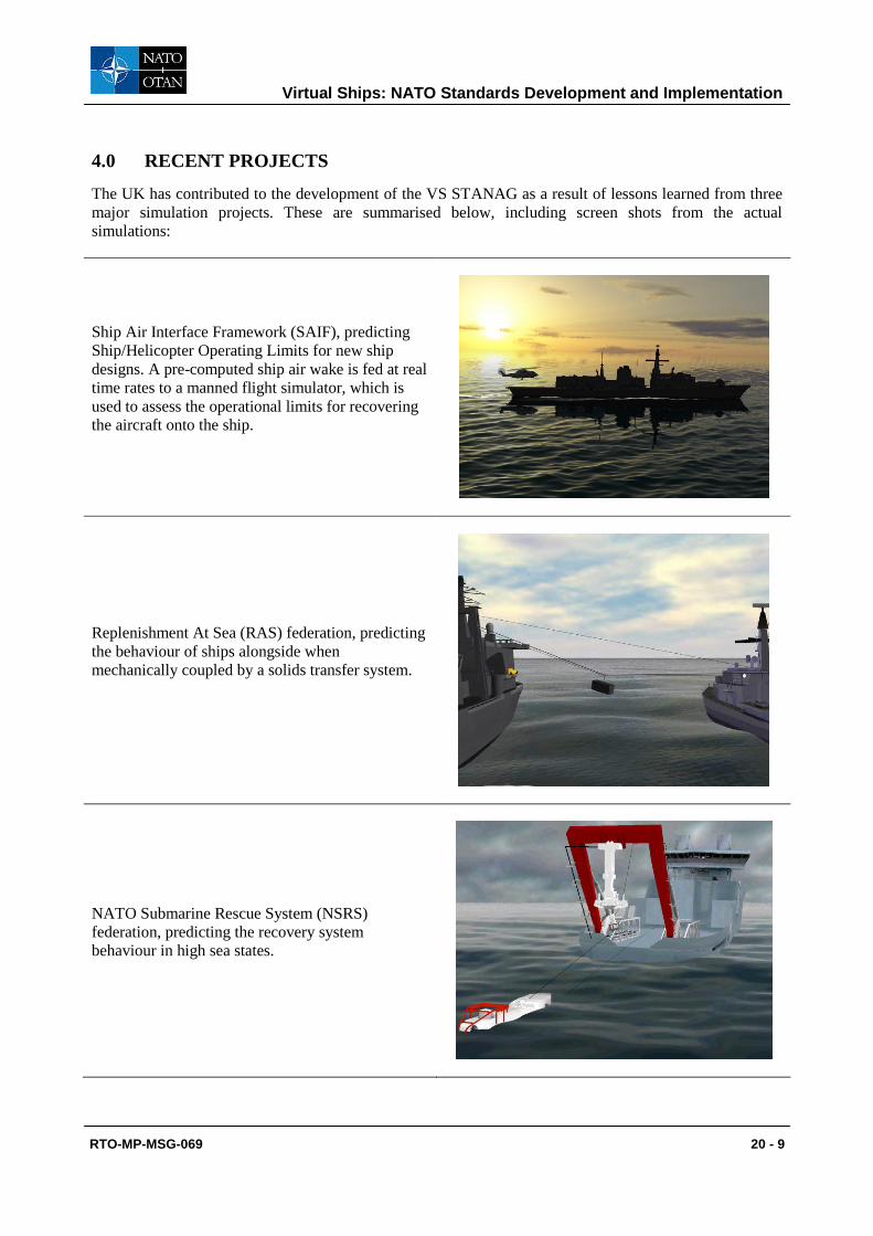
4.0 RECENT PROJECTS
The UK has contributed to the development of the VS STANAG as a result of lessons learned from three
major simulation projects. These are summarised below, including screen shots from the actual
simulations:
Ship Air Interface Framework (SAIF), predicting
Ship/Helicopter Operating Limits for new ship
designs. A pre-computed ship air wake is fed at real
time rates to a manned flight simulator, which is
used to assess the operational limits for recovering
the aircraft onto the ship.
Replenishment At Sea (RAS) federation, predicting
the behaviour of ships alongside when
mechanically coupled by a solids transfer system.
NATO Submarine Rescue System (NSRS)
federation, predicting the recovery system
behaviour in high sea states.
Virtual Ships: NATO Standards Development and Implementation
20 - 10 RTO-MP-MSG-069
Table 3 summarises how each simulation (HLA Federation) was broken down into interoperable federates
(we omit the visualisation federate that is common to all of these federations).
Table 3: Breakdown of the SAIF, RAS and NSRS federations into federates.
The RAS federation was a little inconsistent with the other federates in that it included the hydrodynamics
and aerodynamics within the Environment federate. The most mature of these federations is the NSRS
federation, which utilises the following seven federates:
Environment federate: Responsible for providing the basic environmental data to all other
federates that request it. This includes the wave spectrum, water density, ocean current, air density
and wind velocity.
Aerodynamics federate: Calculates the air flow field and provides air flow field data (including air
flow induced forces and moments) to other federates that request it.
Hydrodynamics federate: Calculates the water flow field and provides water flow field data
(including water flow induced forces and moments and added masses) to other federates that
request it.
Ship motion federate: Responsible for collecting together all the forces and moments that act on
the ship and integrating them to evolve the ship motion. The NSRS federation also included the
ship propulsion forces and helm control within the same federate.
Submersible federate: Responsible for collecting together all the forces and moments that act on
the submersible and integrating them to evolve the SRV motion.
PLARS federate: Responsible for simulating the behaviour of the PLARS mechanical handling
system and providing the forces and moments it exerts on the SRV and ship.
Visualisation federate: Responsible for providing one or more interactive displays of the
simulation using three-dimensional graphics.
Virtual Ships: NATO Standards Development and Implementation
RTO-MP-MSG-069 20 - 11
4.1 Quiescent Period Prediction Project Arrangement
One of the current activities of SG/61 is setting up a Project Arrangement (PA) for a Quiescent Period
Prediction (QPP) simulation capability. This QPP PA aims at better prediction of quiescent periods for
wave induced ship motions. Such motions, particularly in bad weather, limit the operational capability of
the ship, for example they may hinder tasks like launch and recovery of Rigid Hulled Inflatable Boats
(RHIBs), RAS, and Landing Platform Dock (LPD) – Landing Craft Utility (LCU) interactions. The use of
QPP allows for better timing of these tasks to reduce operational limitations.
Classical prediction approaches use statistical data to assess whether a task can be executed or not.
However, this may result in the outcome that an operation is never executed, whereas quiescent periods do
exist. The basic principles QPP are illustrated in Figure 5. It shows an example where current methods
indicate high wave induced motion (red rectangle) while short quiescent periods actually are present
(green rectangles).
Figure 5: Basic principles of Quiescent Period Prediction
One important aspect to consider for a task is the required length of the quiescent period. The available
prediction horizon must be larger than this required time. A short prediction horizon, i.e. up to about five
seconds, is sufficient for tasks like, for example, unassisted landing of Unmanned Air Vehicles (UAVs).
Other tasks, including the tasks mentioned previously, require extended prediction horizons. It is
recognised that for many wave limited tasks the length of the prediction horizons are about one minute [4].
The aim of the QPP PA is to develop a high fidelity simulation of a new QPP system that is capable of
delivering such extended prediction horizons. This simulation is intended as a technology demonstrator
utilising the VS STANAG, which can be further developed into an actual on-board prediction system.
It is envisioned that such predictions can be achieved by remotely measuring waves, using a ship-mounted
radar or lidar system, combined with advanced signal processing and wave prediction. The draft
conceptual model for this system is shown in Figure 6. The components in light blue represent the true
wave environment and ship motions. These are required to provide an environment in which the
measurements and predictions can be made. The green components represent the different sensors, which
simulate measuring the waves and the ship motions. The dark blue components constitute the advanced
motion prediction system. This comprises of the signal processor, wave predictor and the vessel motion
predictor, which are controlled by a process manager that optimizes the prediction quality by tuning
various simulation parameters. Further background and discussion on the feasibility of a QPP simulation
can be found in Crossland et.al. [5].
5m
-5m
5m
-5m
Wave induced motion Limits for given Operation Typical Large Swell
Sea
Decision Method
Classical approach (Statistical
Data)
Never Execute
Operation
Deterministic Look Ahead Prediction for tens of seconds
Often Execute
Operation in safe
prediction window
Outcome
tens of seconds
Short term prediction
Significant periods within operating limits
Extended prediction
Virtual Ships: NATO Standards Development and Implementation
20 - 12 RTO-MP-MSG-069
Figure 6: Draft QPP Conceptual Model
The status of the QPP PA is that an agreement is currently being drafted, which includes descriptions of
the contributions from the participating nations, milestones and deliverables. It is expected that the actual
QPP simulation development will commence in 2010.
5.0 FUTURE VISION
Here we describe our future vision of what it will be like to construct simulations when the VS STANAG
and supporting tools have been well established. As an example, we assume there is a requirement to
determine the highest sea state for which the replenishment of a large ship can be safely undertaken. The
replenishment involves the following processes:
Fuel transfer from a tanker supply ship.
Solids transfer from a fleet supply ship.
Solids transfer from a fleet supply ship via helicopter.
It is clear that federates from the RAS, NSRS and SAIF federations can be re-used to construct the large
ship replenishment federation. Although a federation using QPP has not yet been designed, we shall
assume for the purpose of this exercise that a Ship Motion Sensor federate is available along with a QPP
federate that predicts the quiescent periods. Federates from other nations may also be required. We will
therefore assume the following VS STANAG compliant federates are available from the repository, this
list of federates being sufficient to build the large ship replenishment simulation:
Environment federate
Aerodynamics federate
Vessel motion predictor
Wave predictor
Signal processor
Process manager
Wave sensors
Motion sensors
True ship motions
True global wave environment
Virtual Ships: NATO Standards Development and Implementation
RTO-MP-MSG-069 20 - 13
Hydrodynamics federate
Ship motion federate
Lead ship helm control federate
Following ship helm control federate
Rudder federate
Propeller federate
Roll stabilisation federate
Air vehicle federate
Landing aids federate
Liquids RAS federate
Solids RAS federate
Ship motion sensor federate
QPP federate
Visualisation federate
Most of the preparation work to create the large ship replenishment federation will be in the creation of the
data files to drive the hydrodynamics and aerodynamics federates for the chosen classes of ships. Once
that work has been completed, the federation experiment can begin.
We will assume that a tool is available to help the user construct and execute the federation. We will call
the tool the Virtual Ship Federation Configuration Manager. This tool will guide the user through the
following steps:
Choosing the federates from the list of available federates in the repository.
Downloading of federate executables.
Allocation of federates to each computer in the network.
Configuration of each federate, in terms of what data files they will access.
Copying the federate executables and their data files to each computer.
Initiating the federation execution, ensuring that all required federates join the federation
execution.
Controlling the rate of execution of the federation and allowing pause and continue.
Closing down the federation execution.
Collecting the data files generated by the federation execution for results analysis.
This example clearly shows the power of the framework, in being able to rapidly assemble a completely
new simulation from existing modules, with time being spent only on where it is needed most - on the
aerodynamic and hydrodynamic analyses.
Virtual Ships: NATO Standards Development and Implementation
20 - 14 RTO-MP-MSG-069
6.0 CONCLUSIONS
The goal of rapidly creating simulations of complex ship systems from re-usable components can be
achieved by mandating a standard data exchange mechanism and creating and maintaining a repository of
components that respect that standard. The Virtual Ship STANAG and associated repository will be able
to realise this goal. As part of the modularisation effort, data driven methods have evolved which help to
protect Intellectual Property Rights and deal with other sensitivity issues. Multi-national simulation
projects can be realised with greater efficiency by taking full advantage of the VS STANAG and
repository.
7.0 ACKNOWLEDGEMENTS
This work would not have been possible without the support of the Projects and the Sea Systems Group
within the Defence Equipment and Support organisation.
8.0 REFERENCES
[1] NATO STANAG 4684 "Virtual Ship", 2009.
[2] IEEE 1516-2000 Standard for Modeling and Simulation High Level Architecture: 1516
Framework and Rules, 1516.1 Federate Interface Specification, 1516.2 Object Model Template
(OMT) Specification.
[3] SISO RPR FOM 2.0, Draft 17v3, October 2003.
[4] D R Edgar, J M K Horwood, M R Belmont (2000). ‘The effects of parameters on the maximum
prediction time possible in short term forecasting of the sea surface shape’. International
Shipbuilding Progress, 47 No. 451 pp 287-301.
[5] P. Crossland, B. Ferrier, J. Duncan (2009). ‘The feasibility of developing a quiescent period
prediction system in a simulation environment’, Proceedings of the RINA International
Conference on Computer Applications in Shipbuilding (ICCAS 2009), September 2009,
Shanghai.
Virtual Ships: NATO Standards Development and Implementation
RTO-MP-MSG-069 20 - 15
9.0 ACRONYMS AND ABBREVIATIONS
ANEP Allied Naval Engineering Publication
CFD Computational Fluid Dynamics
FOM Federation Object Model
HLA High Level Architecture
IEEE Institute of Electrical and Electronics
Engineers
IPR Intellectual Property Rights
LPD Landing Platform Dock
LCU Landing Craft Utility
MOU Memorandum Of Understanding
NATO North Atlantic Treaty Organisation
NSRS NATO Submarine Rescue System
PA Project Arrangement
PLARS Portable Launch And Recovery System
QPP Quiescent Period Prediction
RAS Replenishment At Sea
RAO Response Amplitude Operator
RHIB Rigid Hulled Inflatable Boat
RPR Real-time Platform Reference
SAIF Ship Air Interface Framework
SG Study Group
SRV Submarine Rescue Vessel
STANAG Standard Agreement
UAV Unmanned Air Vehicle
VS Virtual Ship
VSR VS Reference
XML eXtensible Mark-up Language
Virtual Ships: NATO Standards Development and Implementation