1 This document contains information property of CNH, Iveco and Fiat Industrial. This document and the contained information cannot be used, copied, transmitted, fully or partly, without prior written authorization of CNH, Iveco and Fiat Industrial. DESIGN ANALYSIS AND SIMULATION Virtual stability simulation of a telescopic handler machine according to the standard UNI EN 1459 Gennaro Monacelli, Stefano Largo, Roberto D’Aria 2013 European Altair Technology Conference, Turin
Transcript
1
This document contains information property of CNH, Iveco and Fiat
Industrial. This document and the contained information cannot be used,
copied, transmitted, fully or partly, without prior written authorization of
CNH, Iveco and Fiat Industrial.
DESIGN ANALYSIS AND SIMULATION
Virtual stability simulation of a telescopic
handler machine according to the standard
UNI EN 1459
Gennaro Monacelli, Stefano Largo, Roberto D’Aria
2013 European Altair Technology Conference, Turin
2
This document contains information property of CNH, Iveco and Fiat
Industrial. This document and the contained information cannot be used,
copied, transmitted, fully or partly, without prior written authorization of
CNH, Iveco and Fiat Industrial.
FOREWORD
• A telescopic handler, or telehandler, is similar
to a forklift with the versatility of a single
telescopic boom that can extend forwards
and upward.
• The development of telehandlers in both
capacity and reach makes them so useful, but
provides scope for unsafe use.
• It is fundamental the understanding of the
kinematic stability behaviour of this
machine.
3/29/2013
DESIGN ANALYSIS AND SIMULATION
3
This document contains information property of CNH, Iveco and Fiat
Industrial. This document and the contained information cannot be used,
copied, transmitted, fully or partly, without prior written authorization of
CNH, Iveco and Fiat Industrial.
DESIGN ANALYSIS AND SIMULATION
PROJECT DESCRIPTION
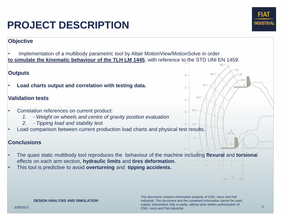
Objective
• Implementation of a multibody parametric tool by Altair MotionView/MotionSolve in order
to simulate the kinematic behaviour of the TLH LM 1445, with reference to the STD UNI EN 1459.
Outputs
• Load charts output and correlation with testing data.
Validation tests
• Correlation references on current product:
1. - Weight on wheels and centre of gravity position evaluation
2. - Tipping load and stability test
• Load comparison between current production load charts and physical test results.
Conclusions
• The quasi static multibody tool reproduces the behaviour of the machine including flexural and torsional
effects on each arm section, hydraulic limits and tires deformation.
• This tool is predictive to avoid overturning and tipping accidents.
3/29/2013
4
This document contains information property of CNH, Iveco and Fiat
Industrial. This document and the contained information cannot be used,
copied, transmitted, fully or partly, without prior written authorization of
CNH, Iveco and Fiat Industrial.
DESIGN ANALYSIS AND SIMULATION
MULTIBODY SIMULATION TOOL FOR TELEHANDLER METHODOLOGY
Step 1: Model setup according to standard EN 1459
Step 3: Instability load evaluation for a discrete number of
angles and payloads
Step 2: Payloads and angles definition by DOE FULL FACTORIAL approach
Step 5: Experimental data Step 4: Load chart diagram output
Boom angle Payload
Reach
He
igh
t
3/29/2013
Correlation
5
This document contains information property of CNH, Iveco and Fiat
Industrial. This document and the contained information cannot be used,
copied, transmitted, fully or partly, without prior written authorization of
CNH, Iveco and Fiat Industrial.
DESIGN ANALYSIS AND SIMULATION
MULTIBODY MODEL OVERVIEW COMPLETE ASSY
Vehicle body
Platform The vehicle model is composed by:
1. Platform (suitable for each angle condition)
2. Vehicle body (condensed masses )
3. Boom (3 arms with simplified shape and
condensed masses + payload)
4. Axle with pivot option
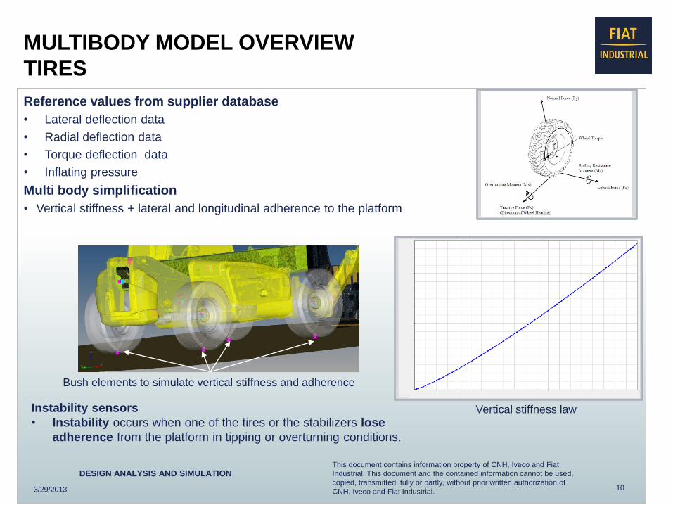
5. Tires (simulated as 3D stiffness)
6. Optional stabilizers to increase the load
capacity if required
Tires Rear axle with pivot
Boom
Stabilizers
Payload
Stabilizers down
in working position
3/29/2013
6
This document contains information property of CNH, Iveco and Fiat
Industrial. This document and the contained information cannot be used,
copied, transmitted, fully or partly, without prior written authorization of
CNH, Iveco and Fiat Industrial.
DESIGN ANALYSIS AND SIMULATION
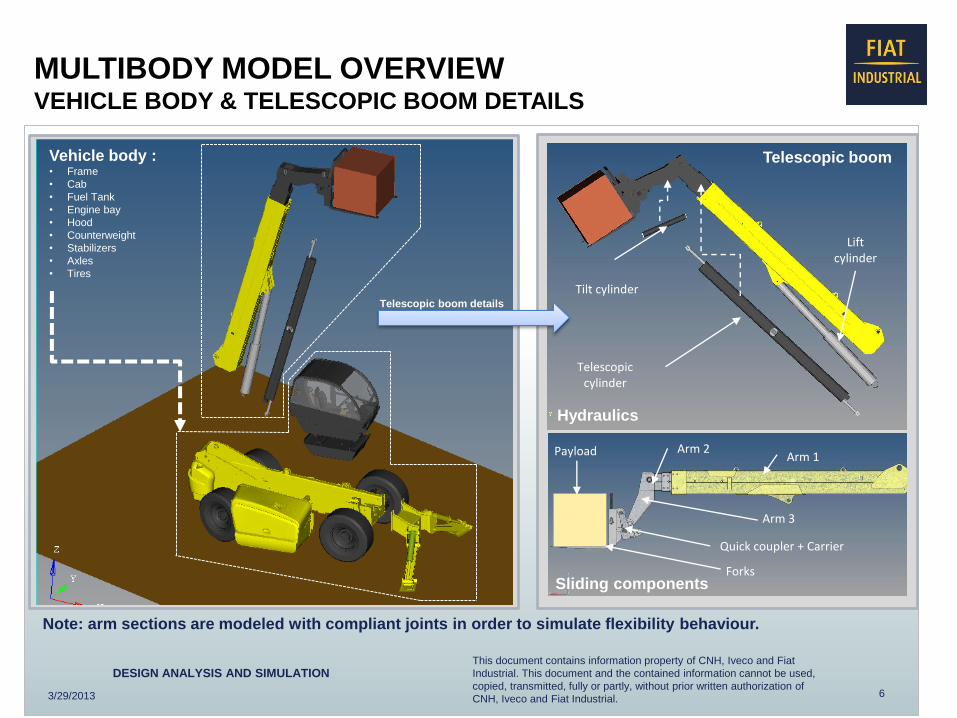
Vehicle body : • Frame
• Cab
• Fuel Tank
• Engine bay
• Hood
• Counterweight
• Stabilizers
• Axles
• Tires
MULTIBODY MODEL OVERVIEW VEHICLE BODY & TELESCOPIC BOOM DETAILS
Telescopic cylinder
Tilt cylinder
Lift cylinder
Arm 3
Arm 2 Arm 1 Payload
Telescopic boom details
Quick coupler + Carrier
Forks
Telescopic boom
Note: arm sections are modeled with compliant joints in order to simulate flexibility behaviour.
3/29/2013
Hydraulics
Sliding components
7
This document contains information property of CNH, Iveco and Fiat
Industrial. This document and the contained information cannot be used,
copied, transmitted, fully or partly, without prior written authorization of
CNH, Iveco and Fiat Industrial.
DESIGN ANALYSIS AND SIMULATION
INSTABILITY CONFIGURATIONS OVERVIEW
1) Boom in horizontal position parallel to platform: Tipping instability
2) Boom in intermediate position (40°- 50°): Border line between tipping and overturning instability 3) Boom at max angle : Overturning instability
3/29/2013
ISO VIEW FRONT VIEW
8
This document contains information property of CNH, Iveco and Fiat
Industrial. This document and the contained information cannot be used,
copied, transmitted, fully or partly, without prior written authorization of