10
VIS Standard and Wheel Motors 30 Series Parts and Repair Information -005
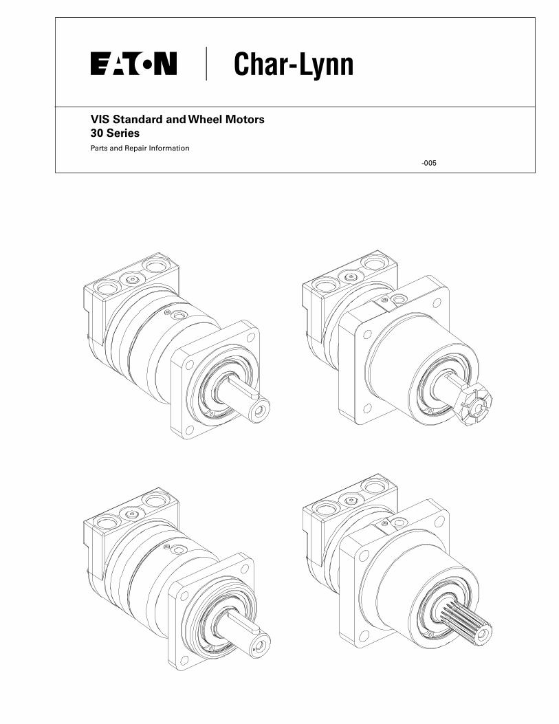
VIS Standard and Wheel Motors30 SeriesParts and Repair Information
-005

Cap Screw23
End Cap1
Seal, Square Cut12
Seal, Square Cut12
O-ring26
End Cap
Seal, Square Cut12
Valve Plate13
Geroler14
Check Ball15
Drive22
Relief Valve Parts
Relief Valve Parts(Shown Enlarged)
Plug/O-ring2
Spring4Shims5Poppet3
O-ring27
Seal, Square Cut12
O-Ring18
Balance Plate (Outer)16
Balance Plate (Inner)17
Back-Up Ring19
Belleville Disc28
Bearing Housing(See Page 3)
Plug/O-ring11
Spring9
Shuttle Piston10
Poppet8Shuttle Valve Parts
(Shown Enlarged)
Dash Pot7
Spring9
Dash Pot7
Poppet8
VIS Standard and Wheel Motors - 30 SeriesTable of Contents
2 EATON Char-Lynn VIS Standard and Wheel Motors C-MOLO-TM004-E March 2008
Parts List .....................................................................................................................................................................................4
Disassembly ...............................................................................................................................................................................5
Reassembly ................................................................................................................................................................................7
Final Assembly ...........................................................................................................................................................................9
How to Order Replacement Parts ............................................................................................................................................10
Exploded View - 30 Series Geroler Motors

VIS Standard and Wheel Motors - 30 Series Geroler Motors
1-3/4 Tapered
40mm Straight
1-1/2” 17T Spline
45mm Tapered
40mm Straight
1-1/2” 17T Spline Wheel Mount (ISO)
Standard Mount (ISO)
Wheel Mount (SAE)
Standard Mount (SAE)
Shaft Face Seal
Shaft Sub-Assembly
Shaft Seal
O-ring
Front Retainer
Retaining Ring
1-3/4 Tapered
40mm Straight
1-1/2” 17T Spline
45mm Tapered
40mm Straight
1-1/2” 17T Spline Wheel Mount (ISO)
Standard Mount (ISO)
Wheel Mount (SAE)
Standard Mount (SAE)
Shaft Face Seal
Shaft Sub-Assembly
Shaft Seal
O-ring
Front Retainer
Retaining Ring
1-3/4 Tapered
40mm Straight
1-1/2” 17T Spline
45mm Tapered
40mm Straight
1-1/2” 17T Spline Wheel Mount (ISO)
Standard Mount (ISO)
Wheel Mount (SAE)
Standard Mount (SAE)
Shaft Face Seal
Shaft Sub-Assembly
Shaft Seal
O-ring
Front Retainer
Retaining Ring
31
31
31
31
31
3120
20
20
20
EATON Char-Lynn VIS Standard and Wheel Motors C-MOLO-TM004-E March 2008 3
21
31
32
30
33
29

VIS Standard and Wheel Motors - 30 SeriesParts List
4 EATON Char-Lynn VIS Standard and Wheel Motors C-MOLO-TM004-E March 2008
Ref. No. Part No. Description Quantity 1 5986496-001 End Cap Assembly 1-1/16-12 O-ring Ports (2) - SAE 1 5986496-002 End Cap Assembly G 3/4 (BSP) O-ring Ports (2) - ISO 1 2 9072-004 Plug Sub Assembly 1X 250003-905 O-ring 1 3 113538-001 Poppet (for relief valve unit only) 1 4 113186-001 Spring (for relief valve unit only) 1 5 16048-500 Shim (for relief valve unit only) A/R 7 112126-001 Sleeve, Dash Pot 2 8 8567-000 Poppet 2 9 230079-000 Spring 2 10 201494-002 Piston, Shuttle 1 11 9266-006 Plug Sub Assembly 1X 250003-906 O-ring 1X 12 14559-015 Seal 4 13 5986477-001 Plate, Valve 1 14 * Geroler 1 15 285020-060 Ball 2 16 5986478-001 Plate, Balancing (Outer) 1 17 203516-001 Plate, Balancing (Inner) 1X 18 112530-135 O-ring 1X 19 14649-001 Ring, Back-up 1 20 4994803-008 Bearing Housing (Standard) 9/16-18 O-ring Case Drain Port - SAE 1 4994803-009 Bearing Housing (Wheel) 9/16-18 O-ring Case Drain Port - SAE 1 4994803-010 Bearing Housing (Standard) G 1/4 (BSP) O-ring Case Drain Port - ISO 1 4994803-004 Bearing Housing (Wheel) G 1/4 (BSP) O-ring Case Drain Port - ISO 1X 21 9080-001 Seal, Shaft Face 1 22 * Drive 1 23 * Screw, 12 PT 9X 26 250183-002 O-ring 1X 27 112530-179 Seal 1 28 203542-001 Spring, Belleville Disc 1 29 16077-063 Ring, Retaining 1 30 112530-044 O-ring 1 31 4992985-010 Shaft S/A (40mm Straight) - SAE 1 4992985-009 Shaft S/A (1-1/2” 17 Tooth Splined) - SAE 1 4992985-006 Shaft S/A (1-3/4” Tapered) - SAE 1 4992985-012 Shaft S/A (40mm Straight) - ISO 1 4992985-014 Shaft S/A (1-1/2” 17 Tooth Splined) - ISO 1 4992985-004 Shaft S/A (45mm Tapered) - ISO 1X 32 14812-001 Seal, Shaft 1 33 202243-001 Front Retainer 1 9900349-000 Seal Kit - Contains Parts Indicated by X * = See Chart A/R = As Required
Displacement Ref. No. 14 Width Ref. No. 22 Length Ref. No. 23 Length cm3/r [in3/r] Geroler mm [inch] Drive mm [inch] Cap Screw mm [inch]
325 [19.8] 5986481-002 28,9 [1.14] 114005-002 129,0 [5.08] 114154-003 115,3 [3.54] 400 [24.4] 5986481-004 35,6 [1.40] 114005-004 135,6 [5.34] 114154-005 122,4 [4.82] 505 [30.7] 5986481-006 44,7 [1.76] 114005-006 144,8 [5.70] 114154-006 131,1 [5.16] 570 [34.9] 5986481-010 50,8 [2.00] 114005-010 151,1 [5.95] 114154-007 135,6 [5.34]

EATON Char-Lynn VIS Standard and Wheel Motors C-MOLO-TM004-E March 2008 5
Tools Required
• 1/4 inch Hex Key (Relief Valve Plug)
• 3/16 inch Hex Key (Shuttle Valve Plug)
• 1/2 Socket (12 Point Drive)
• Torque wrench - 68 Nm [600 lb-in] capacity
Disassembly
1. Cleanliness is extremely important when repairing hydraulic motors. Work in a clean area. Before disconnecting the hydraulic motor thoroughly clean the exterior. Remove motor from application and drain the oil from the motor before disassembly.
2. Remove the 9 cap screws and disassemble the motor in the vertical position as shown in Figure 1. Note placement of small ball checks in Geroler.
3. Remove shuttle valve (and relief valve if applicable) from end cap.
4. Check all mating surfaces. To reduce the chance of leakage, replace any parts that have scratches or burrs. Wash all metal parts in clean solvent. Blow them dry with pressurized air. Do not wipe parts dry with paper towels or cloth as lint in a hydraulic system will cause damage.
VIS Standard and Wheel Motors - 30 SeriesDisassembly
Figure 1
End Cap
Seal, Square Cut
Valve Plate
Geroler
Check Ball
Seal, Square Cut
O-ring
Seal, Square Cut
Drive
Balance Plate (Inner)
Balance Plate (Outer)
O-ring
O-ringBack-Up Ring
Belleville Disc
Bearing Housing
Cap Screw

1-3/4 Tapered
40mm Straight
1-1/2” 17T Spline
45mm Tapered
40mm Straight
1-1/2” 17T Spline Wheel Mount (ISO)
Standard Mount (ISO)
Wheel Mount (SAE)
Standard Mount (SAE)
Shaft Face Seal
Shaft Sub-Assembly
Shaft Seal
O-ring
Front Retainer
Retaining Ring
VIS Standard and Wheel Motors - 30 Series Disassembly Geroler Motors
5. Disassemble bearing housing (4 bearing housings, and 6 shaft sub-assembly options are shown).
Note: Do NOT disasemble shaft sub-assembly.
1-3/4 Tapered
40mm Straight
1-1/2” 17T Spline
45mm Tapered
40mm Straight
1-1/2” 17T Spline Wheel Mount (ISO)
Standard Mount (ISO)
Wheel Mount (SAE)
Standard Mount (SAE)
Shaft Face Seal
Shaft Sub-Assembly
Shaft Seal
O-ring
Front Retainer
Retaining Ring
1-3/4 Tapered
40mm Straight
1-1/2” 17T Spline
45mm Tapered
40mm Straight
1-1/2” 17T Spline Wheel Mount (ISO)
Standard Mount (ISO)
Wheel Mount (SAE)
Standard Mount (SAE)
Shaft Face Seal
Shaft Sub-Assembly
Shaft Seal
O-ring
Front Retainer
Retaining Ring
6 EATON Char-Lynn VIS Standard and Wheel Motors C-MOLO-TM004-E March 2008

Reassembly
Note: Always use new seals when reassembling hydraulic motors. Refer to parts information for seal kit number, replacement parts, and ordering information.
Important: During reassembly, lubricate the new seals with a petroleum jelly such as Vaseline®. Also lubricate machined surfaces with clean hydraulic fluid.
6. Install one poppet, spring and dash pot into shuttle valve bore from valve plate side of end cap.
7. Install shuttle piston from opposite end of shuttle valve cavity.
VIS Standard and Wheel Motors - 30 SeriesReassembly
8. I nstall one shuttle valve poppet, spring and dash pot onto piston.
9. Install one shuttle valve threaded internal hex plug with O-ring. Shuttle plug threads may have light coat of oil or preservative. Torque plug to 360+/-36 lb-in.
10. For a motor with low pressure relief valve, install poppet, shims, spring and plug. Plug threads may have light coat of oil or preservative. Torque plug to 180+/-18 lb-in.
Figure 2
Plug/O-ring
Spring
Shuttle Piston Poppet
Dash Pot
Spring
Dash Pot
Shuttle Valve Parts(Shown Enlarged)
Relief Valve Parts(Shown Enlarged)
End Cap
Optional Relief Valve
Shuttle Valve
Plug/O-ring
Plug/O-ring
Spring
Spring
Spring
SpringPlug/O-ring
Shuttle Valve
Relief Valve
Poppet
Poppet
Poppet
Poppet
Dash Pot
Dash Pot
Shims
Shims
Shuttle Piston
EATON Char-Lynn VIS Standard and Wheel Motors C-MOLO-TM004-E March 2008 7

Note: Always use new seals when reassembling hydraulic motors. Refer to parts list for seal kit number, replacement parts, and ordering information.
Important: During reassembly, lubricate the new seals with a petroleum jelly such as Vaseline®. Also lubricate machined surfaces with clean hydraulic fluid.
11. Install shaft face seal into bearing housing. Use an installa-tion tool as shown, lubricate seal with Mobil EP -2 grease or petroleum jelly (e.g. Vaseline) and compress seal into place.
12. Lightly lubricate seal with Mobil EP -2 grease or petroleum jelly (e.g. Vaseline). Install in groove on front retainer.
13. Lightly lubricate seal lip of shaft pressure seal with Mobil EP-2 grease or petroleum jelly (e.g. Vaseline). Place seal on assembly tool, and press into bore of front retainer. Press until seal makes positive stop with front retainer shoulder. Protect inside diameter shaft seal area from damage.
8 EATON Char-Lynn VIS Standard and Wheel Motors C-MOLO-TM004-E March 2008
VIS Standard and Wheel Motors - 30 SeriesReassembly
Figure 4
Figure 6
Shaft Face SealInstallation Tool
Shaft Face Seal(in Installation Tool)
Shaft Face Seal(Installed in Bearing Housing)
Bearing Housing
O-RingInstallation Tool
Shaft Seal
Front Retainer
Retaining Ring
Front Retainer with Seals
Tool (Shaft Bullet)
Shaft and Bearing Assembly
Housing
Shaft Face SealInstallation Tool
Shaft Face Seal(in Installation Tool)
Shaft Face Seal(Installed in Bearing Housing)
Bearing Housing
O-RingInstallation Tool
Shaft Seal
Front Retainer
Retaining Ring
Front Retainer with Seals
Tool (Shaft Bullet)
Shaft and Bearing Assembly
Housing
14. Install shaft and bearing assembly in bearing housing, you may need a press to install shaft and bearing assembly.
15. Before installing retainer, place a protective sleeve of bullet over shaft. Grease inside diameter of shaft seal. To prevent damage to seal, install front retainer over shaft with a twisting motion. Do not cut or distort shaft seal. Damage to shaft seal will cause external leakage.
Figure 5
Shaft Face SealInstallation Tool
Shaft Face Seal(in Installation Tool)
Shaft Face Seal(Installed in Bearing Housing)
Bearing Housing
O-RingInstallation Tool
Shaft Seal
Front Retainer
Retaining Ring
Front Retainer with Seals
Tool (Shaft Bullet)
Shaft and Bearing Assembly
Housing

End Cap
Seal, Square Cut
Valve Plate
Shuttle Flow Hole
Geroler
Check Ball
Seal, Square Cut
O-ring
Shuttle Flow Hole
Seal, Square Cut
Drive
Longest Spline(if assymetric)
Balance Plate (Inner)
Balance Plate (Outer)
Shuttle Flow Hole
O-ring
O-ringBack-Up Ring
Belleville Disc
Bearing Housing
Cap Screw
End Cap
Seal, Square Cut
O-ring
Geroler
Check Ball
Seal,SquareCut End Cap
Seal, Square Cut
O-Ring
Geroler
Check Ball
SealSquare Cut
Figure 7
91
4
7
2
5
8
3
6
Figure 8
16. Install two O-ring seals (130,9 [5.16] ID & 92,3 [3.63] ID) into the face grooves of the bearing housing. Install back-up ring (56,1 [2.21] OD) over O-ring (48,9 [1.93] ID) with flat side up. Back-up ring and O-rings may be greased to assist in retaining parts.
17. Install main drive with longest spline length (if asymmetric) into output shaft spline.
18. Place outer and inner balance plate on the bearing housing. Align shuttle flow cavity of outer balance plate with the shuttle flow cavity of the bearing housing.
19. Grease and place two O-ring seals (130,9 [5.16] ID) into the grooves on both sides of the Geroler.
20. Place two steel balls into seats of star (one per seat). Grease sufficiently to retain balls when Geroler is assembled.
21. Place Geroler onto the outer bal-ance plate making sure that the steel balls stay seated. Align the shuttle flow cavity of the Geroler with the shuttle flow cavity of the outer balance plate.
22. Install valve plate on Geroler making sure to align necessary shuttle flow holes.
23. Place O-ring (130,9 [5.16] ID) into large face groove of the end cap. Place O-ring (21,0 [0.83] ID) into small face groove of the end cap. Seals must have sufficient coating of petroleum jelly to assist in retain-ing the seal in the groove.
24. Carefully invert end cap and place onto valve plate making sure that the shuttle flow cavities are aligned.
25. Lubricate nine caps screws with DTE-26 and install into flange- Geroler-end cap stack. In a crisscross pattern (See Figure 8), pre-torque screws to 60+/-10 lb-ft. Finally, in a crisscross pattern, tighten screws to 105+/-5 lb-ft.
26. Install two cap plugs in main ports (Optional).
27. Install key and hex nut into shaft if required.
EATON Char-Lynn VIS Standard and Wheel Motors C-MOLO-TM004-E March 2008 9
VIS Standard and Wheel Motors - 30 SeriesFinal Assembly

160 0000 005159 0000 005
© 2008 Eaton CorporationAll Rights ReservedPrinted in USADocument No. C-MOLO-TM003-EMarch 2008
Each order must include the following:
1. Product Number 2. Date Code 3. Part Name4. Part Number5. Quantity of Parts
For more detailed information, please contact:
Eaton’s Hydraulics Operations14615 Lone Oak RoadEden Prairie, MN 55344
For specification and performance data, refer to catalog E-MOLO-MC001-E3.
Eaton Hydraulics Operations EuropeRoute de la Longeraie 71110 MorgesSwitzerlandTel: +41 (0) 21 811 4600Fax: +41 (0) 21 811 4601
Eaton Hydraulics Operations USA14615 Lone Oak RoadEden Prairie, MN 55344USATel: 952-937-9800Fax: 952-294-7722www.hydraulics.eaton.com
Eaton Hydraulic Operations Asia Pacific 11th Floor Hong Kong New World Tower 300 Huaihai Zhong Road Shanghai 200021 China Tel: 86-21-6387-9988 Fax: 86-21-6335-3912
VIS Standard and Wheel Motors - 30 SeriesHow to Order Replacement Parts


