5.6 Piping Loads (P) for Pipe Supports/Trestles 14
6 DESIGN REQUIREMENTS FOR SPECIFIC APPLICATIONS 15
6.1 Vertical Loading 15
6.2 Friction Force (Longitudinal and Transverse) 15
6.3 Anchor and Guide Force (Thermal load) 15
6.4 Loading on Intermediate Beam at Tier Level 15
6.5 Loading on Longitudinal Beams 16
6.6 Cable Tray/Ducts and Walkway Loads 16
6.7 Wind Force 16
7 Live Loads (L) 16
7.1 General 16
7.2 Live Loads on different structures/buildings 17 7.2.1 Service Platform 17 7.2.2 Substation/Control Room 17 7.2.3 Office building 17 7.2.4 Staircase 17
8 Contingency Loads 18
8.1 RCC Structures 18
VISAKH MARKETING INSTALLATION REISTEMENT
PROJECT WHITE OIL TERMINAL
Doc No:254624-400-DB-CIV-001 Rev: B Page 4 of 45
P:\Andheri\IndiaProject\254624 HPCL- White Oil Terminal\02 Civil\1-DELIVERABLE LIST (ISSUED
FOLDER)\DOCUMENT\DESIGN BASIS\Design Basis_B.doc
8.2 Structural Steel 18
9 Earth pressure (H) & Buoyancy: 18
10 Wind Loads (W) 18
11 Seismic Loads (S) 19
12 Thermal Loads (TL) 20
13 Impact Loads (I) 21
14 Vibration Loads (V) 21
15 Surcharge/Overburden Loads (B) 21
16 Load Combinations 21
16.1 General 21
16.2 Load Factors and Combinations 21
17 Concrete Structures – Design 23
17.1 General 23
17.2 Foundations 24
17.3 Minimum Foundation Sizes 24
17.4 Piles and Pile Caps 24
17.5 Anchor Bolts 25
17.6 Minimum Cover Requirements to Main Reinforcement 25
17.7 Staircase 25
17.8 Concrete Grade 26
17.9 Reinforcement Bars 26
17.10 Minimum Thickness of concrete members 26
17.11 Allowable Deflections for concrete buildings 26
18 Masonry Structures 27
18.1 General 27
19 Steel Structures design 27
19.1 General 27
19.2 Miscellaneous 28
20 Allowable Deflections for structural steel buildings 28
20.1 General 28
20.2 Crane Beams or Girders 28
21 Surface Drainage, Paving & Sewerage: - 29
21.1 Table showing paving type selection 29
VISAKH MARKETING INSTALLATION REISTEMENT
PROJECT WHITE OIL TERMINAL
Doc No:254624-400-DB-CIV-001 Rev: B Page 5 of 45
P:\Andheri\IndiaProject\254624 HPCL- White Oil Terminal\02 Civil\1-DELIVERABLE LIST (ISSUED
FOLDER)\DOCUMENT\DESIGN BASIS\Design Basis_B.doc
21.2 Joints 30
22 Drainage General 31
22.1 Drain details 31
22.2 Storm Water Drainage 31
22.3 Oily Water Sump system (OWS): 32
23 Site grading & roads: - 32
23.1 Site Grading: - 32
23.2 Roads:- 32
24 RCC bund walls & bunded area discharge: 33
24.1 Bunded area discharge: 33
25 Substations buildings and blast resistant design: 33
25.1 General 33
25.2 General principles of steel tank foundation design: 34
25.3 Analysis & design procedure for RCC underground tanks: 34
26.3 Building Services 38 26.3.1 Water supply, Distribution and Drainage Sanitary Services 38 26.3.2 Electrical Services 38 26.3.3 Air conditioning and Heating 39
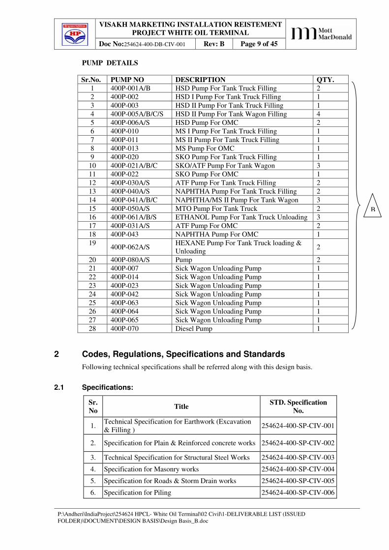
All Pipe/Cable racks shall be Structural Steel with Pile foundations as per soil report. All
Pipe/Cable Tracks shall be Slippers with Either Open/Pile foundations as per soil report.
All Tanks shall be supported on pile foundations.
The shed type buildings shall be following
Engineering Store & Lube Godown, T/T Loading Gantry sheds, Product Pump House TT
Loading, Pump House TW Gantry, Calibration Shed, Lube Yard, Garrage and Fire Stations.
5 Design Loads
5.1 General
5.1.1 Structures shall be designed to have sufficient structural capacity and integrity to resist safely
and effectively all loads and effects of load combinations that may reasonably be expected.
5.1.2 The design loads used for the structures, buildings and foundations shall conform to the
requirements of the governing codes and specifications. As a minimum the design loads shall
include dead load, operating loads, live load, rain load, wind load and seismic load. Where
applicable, the design loads shall also include thermal load, anchor loads, hydro test load,
impact load, vibration load, surcharge load and bundle pull loads.
5.1.3 The units to be used for design and drawings are SI units.
5.2 Dead Loads (D)
5.2.1 Dead load comprises of the weight of all permanent construction including walls, fire-
proofing, floors, roofs, partitions, stairways, fixed services and other equipments excluding
their content.
Dead loads (D) shall consist of total loads due to the structure (framing, walls, roofing etc.),
equipment, piping, insulation, refractory, overburden soil, and other load permanently
supported by the structure. If in-situ hydro test is planned, the dead load shall include water
VISAKH MARKETING INSTALLATION REISTEMENT
PROJECT WHITE OIL TERMINAL
Doc No:254624-400-DB-CIV-001 Rev: B Page 13 of 45
P:\Andheri\IndiaProject\254624 HPCL- White Oil Terminal\02 Civil\1-DELIVERABLE LIST (ISSUED
FOLDER)\DOCUMENT\DESIGN BASIS\Design Basis_B.doc
filled vessels and piping. Foundation dead loads shall contain the weight of the soil
immediately above the foundation.
Weight of the structure: The self-weight of the structure shall be calculated based on the
following unit weights of the structure:
Items Unit Weight (kN/m3)
Steel 78.5
Reinforced Concrete 25
Plain Concrete 24
Water 10
Soil (dry earth ) 18
Soil in Ground Water 8
Bricks Masonry 20
Dry Sand 18
5.3 Static & Dynamic Equipment Empty Loads (E)
Equipment loads shall be supplied by Vendor drawings and/or data sheets and shall include
empty weight.
The empty weight of the static process equipment including all fixtures, platforms, ladders,
attached piping, pipe supports & insulation (if applicable) shall be considered. If piping
weight is not indicated separately or included in the weight of the equipment, the same shall
be considered as 10% of the weight of the equipment. The empty (dead) weight shall be
considered as per inputs received from vendors. Static equipments viz. Vessels, tanks etc.
Dead/Empty Weight of equipment – Weight of dynamic/rotary equipment like pumps/motors,
D.G. Sets, and skid-mounted equipment shall be derived as far as possible from
manufacturer’s data and includes piping data. Insulation installed on piping and equipment
shall be also considered.
Empty/dead weight – Fabricated/Erected equipment weight from manufacturer’s data.
5.4 Equipment Operating Loads (EO)
Operating Weight of equipment – Weight of equipment like pumps, tanks and vessels shall be
derived as far as possible from manufacturer’s data and includes mechanical/piping data.
Insulation installed on piping and equipment shall be also considered.
The operating loads (OP) for the process and utility equipment, including piping (P), shall be
the dead loads plus weight of the liquid / contents under normal conditions at maximum
operating level. Permanent stored materials for operation shall be included as operating loads.
Vessels, Tanks etc. – The weight to be included in the calculations depend on the extent to
which it is filled with liquid.
Operating weight = Weight of the maximum contents of the equipment during operating
condition of plant plus the empty weight.
5.5 Equipment Hydro-Test Load (EH)
Hydrostatic test load = The weight of Full volume of the water filled in Equipment plus the
empty weight.
VISAKH MARKETING INSTALLATION REISTEMENT
PROJECT WHITE OIL TERMINAL
Doc No:254624-400-DB-CIV-001 Rev: B Page 14 of 45
P:\Andheri\IndiaProject\254624 HPCL- White Oil Terminal\02 Civil\1-DELIVERABLE LIST (ISSUED
FOLDER)\DOCUMENT\DESIGN BASIS\Design Basis_B.doc
Equipment hydro test loads (EH) shall consist of the equipment empty weight plus the weight
of the test content (usually water) contained in the system to be considered.
Foundation design to take account of:
- fully dressed load with hydro test.
- undressed condition with worst wind load effects.
For hydro testing of vessels, piping and the like allow for test case full of water.
Under hydro-test condition the wind force shall be considered as 25% of normal loading.
5.6 Piping Loads (P) for Pipe Supports/Trestles
5.6.1 Pipe loads (P) in Operating Condition shall be considered as follows:
Up to 300 mm diameter 1.0 KN/ Sq. m Dead Load (Self weight)
1.8 KN/ Sq. m Live Load (Contents weight)
300 mm dia. and over Consider individual/actual point loads as per piping inputs
For pipe racks, where actual loads from pipes are used, they shall not be less than 2.0 KN/ Sq.
m on each level.
Friction Force (Longitudinal & Transverse)
Longitudinal & transverse friction force in (both directions) 10 % of design vertical load of
pipes for four or more pipes supported on a tier. (This is done due to reversible flow directions
and forces)
Longitudinal friction force (30 % of design vertical load of pipes) & transverse force (10 % of
design vertical load of pipes) for single to three pipes supported on a tier for global design
where as for local beam member design for single pipe frictional force of 30% to be
considered in longitudinal and transverse direction or as per piping/stress load inputs. The
local beam member design shall not be combined with seismic/wind loads.
For Pipe-racks; longitudinal friction force shall be considered as uniformly distributed over
the entire span of the beam at each tier and transverse friction force shall be considered as a
concentrated load at each tier level.
Friction forces on T-supports & trestles shall be considered as longitudinal 30% of the vertical
loading & transverse 10% of the vertical loading. Both longitudinal and transverse friction
forces shall be considered to act simultaneously.
5.6.2 Electrical and Instrumentation information shall be investigated to determine the approximate
weight, location of the electrical trays and/or conduits. A minimum weight of 1.2 KN/ Sq. m
shall be used for single level trays and 3.0 KN/ Sq. m for double trays, regardless of the tray
width.
5.6.3 Special consideration shall be given to unusual loads such as large valves, unusual piping or
electrical configurations, etc.
5.6.4 Anchor loads (TA) shall be as per the Stress analysis piping loads provided by Stress Group.
5.6.5 If no Stress analysis piping loads is available at the time of design, the following minimum
anchor loads shall be used:
(a) for pipe rack span less than 3600mm, apply 5 KN at the middle of the span;
(b) for pipe rack span more than 3600mm, apply 5 KN at 1/4 and 3/4 of the span;
5.6.6 Anchor loads shall be only applied on piping level.
VISAKH MARKETING INSTALLATION REISTEMENT
PROJECT WHITE OIL TERMINAL
Doc No:254624-400-DB-CIV-001 Rev: B Page 15 of 45
P:\Andheri\IndiaProject\254624 HPCL- White Oil Terminal\02 Civil\1-DELIVERABLE LIST (ISSUED
FOLDER)\DOCUMENT\DESIGN BASIS\Design Basis_B.doc
6 DESIGN REQUIREMENTS FOR SPECIFIC APPLICATIONS
PIPE RACK
For designing the pipe rack superstructure and foundation the following loads shall be
considered.
6.1 Vertical Loading
Actual weights of pipes coming at each tier shall be calculated. In calculating the actual weight of
pipe, the class of pipe, material content and insulation, if any, shall be taken into consideration.
Minimum Insulation density shall be taken as 2600 N/m3. In case of gas/steam carrying pipes,
the material content shall be taken as 1/3rd volume of pipe filled with water. The total actual
weight thus calculated shall then be divided by the actual extent of the span covered by the pipes
to get the uniform distributed load per unit length of the span. To obtain the design uniformly
distributed load over the entire span, the udl (uniformly distributed load) obtained as above shall
be assumed to be spread over the entire span. However, minimum loading for any pipe rack shall
not be less than 2.0 KN/m2. In case, the calculated loading is higher than 2.0 kN/m2, this shall be
rounded off to the nearest multiple of 0.25 (i.e. 2.25, 2.50, 2.75 kN/m2).
6.2 Friction Force (Longitudinal and Transverse)
Where the pipes are of similar diameter and service condition, the friction force at each tier on
every portal, both in longitudinal and transverse directions shall be 10% of the design vertical
loading of the pipes for four or more pipes supported on a tier for global design, and 30% of the
design vertical loading of the pipes in longitudinal direction & 10% of the design vertical loading
of the pipes in transverse direction for single to three pipes supported on a tier. Longitudinal
friction force shall be considered as uniformly distributed over the entire span of the beam at each
tier and transverse friction force shall be considered as a concentrated load at each tier level.
Friction force on T-supports and trestles shall be taken as 30% and 10% in longitudinal and
transverse directions respectively of the vertical loading. Both longitudinal and transverse friction
forces shall be considered to be acting simultaneously.
For local beam/member design shall be checked for frictional forces 30% of the vertical loads in
both longitudinal and transverse directions acting simultaneously. The local beam design shall
not be checked for seismic/wind loads acting simultaneously along with the frictional forces.
6.3 Anchor and Guide Force (Thermal load)
The Anchor or Guide Forces in longitudinal and transverse directions shall be as per piping
inputs.
6.4 Loading on Intermediate Beam at Tier Level
Intermediate beam at tier level shall be designed for 25% of load on main portal beams in
transverse direction. A reduction of 10% in vertical loading shall be considered for main portal
beams if intermediate beams are provided.
VISAKH MARKETING INSTALLATION REISTEMENT
PROJECT WHITE OIL TERMINAL
Doc No:254624-400-DB-CIV-001 Rev: B Page 16 of 45
P:\Andheri\IndiaProject\254624 HPCL- White Oil Terminal\02 Civil\1-DELIVERABLE LIST (ISSUED
FOLDER)\DOCUMENT\DESIGN BASIS\Design Basis_B.doc
6.5 Loading on Longitudinal Beams
Longitudinal beams connecting portal columns shall be sufficiently strong to sustain 50% of the
load on the transverse beams. This total load shall be assumed as two equal concentrated loads
acting at 1/3rd span. Other longitudinal axial forces coming on it from the design of the
supporting system shall also be simultaneously taken into account in the design of the
longitudinal beam. Friction and Anchor Forces, if specifically given by the piping stress engineer
shall also be catered for in the design. Loads from monorails, when supported from these beams,
shall also be considered to be acting simultaneously along with all other loads mentioned above.
These beams shall be designed locally for monorail loads. The monorail loads shall not be
combined with wind & seismic. It shall be considered for local monorail member design.
6.6 Cable Tray/Ducts and Walkway Loads
The estimated actual load from electrical trays and instrumentation ducts shall be considered at
the specified locations, together with walkways, if provided.
6.7 Wind Force
Transverse wind loading shall be calculated depending on the width of the Pipe Rack as follows:
a) Basic wind pressure shall be considered as per IS: 875.
b) To calculate wind load in transverse direction of pipe-rack, a projected height of 1.25m/1.5m/2.0m shall be considered on all tiers irrespective of height between two tiers of rack widths of 4m/6m/8m and 10m respectively. For pipe-racks of widths greater than 10m, the above projected height shall be taken as 0.8[diameter of largest pipe including insulation (m)] + tan 10° [width of rack (m)]. However, this shall not exceed the height between consecutive tiers.
7 Live Loads (L)
7.1 General
7.1.1 Live loads (L) shall consist of loads due to the intended use and occupancy of the structure.
Minimum live loads due to use and occupancy shall be as follows, unless otherwise specified
on process / assignment drawings. Reduction in Live load shall be per Cl 3.2 of IS: 875 - Part
II.
Area Specified Uniform Loads
(KN/m2)*
Specified Point Loads
(KN)**
Ladder Rungs - 2.2
Office floor, labs, walkways 5.0 9.0
Minimum roof load 1.5 3.75
Operating, maintenance, platform 5.0 6.7
Suspended piping on main roof 1.0 None
Vessel platform 5.0 None
Access platform 3.0 None
Electrical, computer and control room 10.0 9.0
VISAKH MARKETING INSTALLATION REISTEMENT
PROJECT WHITE OIL TERMINAL
Doc No:254624-400-DB-CIV-001 Rev: B Page 17 of 45
P:\Andheri\IndiaProject\254624 HPCL- White Oil Terminal\02 Civil\1-DELIVERABLE LIST (ISSUED
FOLDER)\DOCUMENT\DESIGN BASIS\Design Basis_B.doc
Toilet bathroom 2.0 9.0
Stair / Corridors / Passages 5.0 4.5
* Minimum specified uniform loads and minimum specified concentrated loads do not act
concurrently. ** Distribute concentrated loads over 300mm x 300mm area. For evaluation of local effects
of crushing (Ref. Cl 3.1.1 IS 875 Part II).
7.1.2 For railings, a horizontal force of 1.0kN at any one point or uniform load of 0.75kN/m shall be
used.
7.1.3 For structural calculations, the actual loading situation shall be adhered to if these are more
stringent. If heavy equipment has to be supported, the weight of this equipment in excess of
the live load specified above shall be taken into account.
7.1.4 For garages and fire stations, the live loads shall also include the maximum weight of the
trucks and/or fire fighting equipment.
7.2 Live Loads on different structures/buildings
Live loads shall, in general, be as per IS: 875. However, the following minimum live loads
shall be considered in the design of structures to account for maintenance and erection as
well:\
7.2.1 Service Platform
Vessel/Tower 3.0 KN/m2
Isolated platform (for valve operation) 3.0 KN/m2
Access way 2.5 KN/m2
Cross over 2.0 KN/m2
7.2.2 Substation/Control Room
Panel floor 10.0 KN/m2
Partitions 1.0 KN/m2
7.2.3 Office building
Office area 3.0 KN/m2
Lobby 5.0 KN/m2
Exit way 5.0 KN/m2
Partitions 1.0 KN/m2
7.2.4 Staircase
Office 5.0 KN/m2
Substation/Control Room 5.0 KN/m2
Laboratory 3.0 KN/m2
Service platform 2.5 KN/m2
VISAKH MARKETING INSTALLATION REISTEMENT
PROJECT WHITE OIL TERMINAL
Doc No:254624-400-DB-CIV-001 Rev: B Page 18 of 45
P:\Andheri\IndiaProject\254624 HPCL- White Oil Terminal\02 Civil\1-DELIVERABLE LIST (ISSUED
FOLDER)\DOCUMENT\DESIGN BASIS\Design Basis_B.doc
8 Contingency Loads
8.1 RCC Structures
All floor slabs and beams shall be designed for a concentrated load of 10 KN acting
simultaneously with the uniform live load, but not with actual concentrated loads from
equipment, piping etc. This load shall be placed to result in maximum moment and / or
maximum shear, it shall not be considered for the design of columns, foundations and in
overall frame analysis. For floor slabs, the load shall be considered to be distributed over an
area of 0.75 m x 0.75 m.
8.2 Structural Steel
For process plants, the following contingency additional loading shall be applied to individual
beam elements. These shall be applied as point loads to produce worst shear and bending
stresses:
Platform Walkways 3 KN
Secondary Floor Trimmers 5 KN
Primary beams 10 KN
9 Earth pressure (H) & Buoyancy:
For evaluating earth pressure on walls of trenches and pits co-efficient of earth pressure at rest
shall be considered, its minimum value being taken as 0.5. If a higher value is obtained from
soil characteristics, the same shall be adopted.
Temporary rise of ground water level shall be duly considered and hydrostatic pressure arising
there from shall be considered for design of trenches, pits and basements more than 1.25 m in
depth.
Maximum ground water level is around 0.7 m below Finished Ground Level.
Factor of safety for underground tanks etc against floatation shall be greater than 1.2. During
construction, factor of safety shall be at least greater than 1.05.
10 Wind Loads (W)
Wind loads (W) shall be in accordance with the applicable codes, specifications and
recommended practices listed in IS 875, Part III.
The effects of wind induced vibration shall be taken into effect as required by the applicable
codes, specifications and recommended practices listed in Section 2.1.
11.2 Seismic load (S) induced on structures, buildings, equipments, and foundations shall be calculated in accordance of the requirements the IS standard as mentioned in Section 2.
11.3 Factors for the calculation of the seismic loading, i.e. seismic zone, soil profile, etc. shall be as per Geotechnical Investigation and in accordance with the requirements of the IS standard as mentioned in Section 2.
11.4 Basic Seismic Loading parameters:
Ref. Annex E, IS 1893 Part 1, 2002, Seismic Zone for HPCL site – II,
Seismic Zone factor, Z = 0.10,
Design horizontal seismic coefficient, Ref. Cl 6.4.2, IS 1893: 2002
The Fundamental natural period shall be as per, Ref. Cl 7.6, IS 1893: 2002
For percentage of live load to be considered during seismic action for load evaluation, Ref
Table 8, IS 1893, Pt 1, 2002.
The seismic base shear VB = Ah* W
12 Thermal Loads (TL)
Generally the thermal loads shall be issued by piping stress analysis group. These loads shall be used for design of pipe supports/structures.
The design of structure and foundation shall satisfy following minimum requirements.
12.1 The calculation of thermal loads (TL) shall be as per the requirements of the governing codes and specification.
12.2 Thermal Loads caused by expansion and contraction due to a change in temperature from the erection condition shall be carefully considered. Included are forces due to anchorage of piping and equipment, sliding and rolling of equipment, and expansion and contraction of structures.
12.3 Thermal loads due to the constraints and frictional forces of piping shall be considered as follows:
(a) A minimum of 10% (in both longitudinal & transverse directions) of the gravity load for the
pipe supports / sleepers carrying 4 or more lines.
(b) A minimum of 30% of the gravity load in longitudinal direction & 10% in transverse
direction on pipe supports / sleepers carrying less than 4 lines.
Equipment on structural supports shall be analyzed for thermal loads to be resisted by the structure and provisions shall be made to relieve the forces too large for the equipment or the supporting structure. The friction factors to be used are the ones defined hereunder.
Steel To Steel = 0.3
VISAKH MARKETING INSTALLATION REISTEMENT
PROJECT WHITE OIL TERMINAL
Doc No:254624-400-DB-CIV-001 Rev: B Page 21 of 45
P:\Andheri\IndiaProject\254624 HPCL- White Oil Terminal\02 Civil\1-DELIVERABLE LIST (ISSUED
FOLDER)\DOCUMENT\DESIGN BASIS\Design Basis_B.doc
Steel to PTFE Pad = 0.08
Steel to Concrete = 0.4
13 Impact Loads (I)
Impact loads (I) shall be calculated in accordance with the requirements of IS: 875 (Part 5) and IS: 2974 codes. For loads being given by equipment supplier, impact loads shall be as per information given on civil assignment drawing of equipment supplier. Impact loads shall be considered for local member design & it shall not be used with wind/seismic load cases.
14 Vibration Loads (V)
Vibration loads (V) shall be as per manufacturer’s recommendations & Indian standards.
A three-dimensional vibration analysis for rotating equipment foundations shall be done to satisfy manufacturer’s recommendation if any, and provisions of Indian standards.
The natural frequency of the supporting structures and foundations shall be below 80 % or above 120 % of the natural frequency of the machine in the first mode.
15 Surcharge/Overburden Loads (B)
Surcharge loads (B) shall be considered for structures (tanks, pits etc.) and walls retaining soil, if any, in addition to usual soil pressure.
Surcharge pressure shall be generally considered as 15kN/m2 on top slab and also on adjacent ground.
16 Load Combinations
16.1 General
16.1.1 Structures, buildings and foundations shall be designed for all individual load cases and the various load combinations that may act together.
16.1.2 Load combinations using Working Stress Design or Limit State Design shall be as per the requirements of the IS standard as mentioned in Section 2.
16.2 Load Factors and Combinations
16.2.1 Load notations shall be as follows :
D – Dead Load
L – Live / Imposed Load
E – Equipment Load (Empty Equipment)
EH – Equipment Hydro test Load (Equipment with water load)
EO – Equipment Operating Load (Equipment with operating fluid)
W – Wind Load
S – Seismic / Earthquake Load
OP – Operating Load of piping and fluids
TL – Thermal Load
TA – Thermal Anchor Load
BP – Bundle Pull Load
V – Vibration Loads
H – Earth Pressure Load
VISAKH MARKETING INSTALLATION REISTEMENT
PROJECT WHITE OIL TERMINAL
Doc No:254624-400-DB-CIV-001 Rev: B Page 22 of 45
P:\Andheri\IndiaProject\254624 HPCL- White Oil Terminal\02 Civil\1-DELIVERABLE LIST (ISSUED
FOLDER)\DOCUMENT\DESIGN BASIS\Design Basis_B.doc
B – Surcharge Load
f1 – factor for Load
16.2.2 Strength load combinations for buildings with or without equipment shall be as per IS: 456-2000.
1.5*D
1.5*D + 1.5*L
1.5*D + 1.5*L + 1.5*E
1.5*D + 1.5*EH
1.5*D + 1.5*L + 1.5*EO
1.5*D + 1.5*(W or S)
0.9*D + 1.5*(W or S) reversible wind/seismic forces
1.5*D + 1.5*E + 1.5*(W or S) reversible wind/seismic forces
0.9*D + 0.9*E + 1.5*(W or S) reversible wind/seismic forces
1.5*D + 1.5*EO + 1.5*(W or S) reversible wind/seismic forces
1.2*D + 1.2*L + 1.2*(W or S) reversible wind/seismic forces
16.2.4 IS: 800 Allowable stress design method shall be used with following load combinations for design of structural steel open structures/sheds/pipe-racks. This is done in view of use of STAAD PRO software for the analysis & design.
D + OP + TA + TL + V
D + OP + TA + TL + V +E
D + OP + TA + TL + V +EH
D + OP + TA + TL + V +EO
D + OP + L + TA + TL + V
D + OP + L + TA + TL + V +E
D + OP + L + TA + TL + V +EH
D + OP + L + TA + TL + V +EO
D + OP + TA + TL + EO
D + OP + TA + TL + EO + W reversible wind forces
D + OP + TA + TL + EO + S reversible seismic forces
D + OP +H + L
D + OP + H + B
0.9*D +0.9*OP +W reversible wind/seismic forces
VISAKH MARKETING INSTALLATION REISTEMENT
PROJECT WHITE OIL TERMINAL
Doc No:254624-400-DB-CIV-001 Rev: B Page 23 of 45
P:\Andheri\IndiaProject\254624 HPCL- White Oil Terminal\02 Civil\1-DELIVERABLE LIST (ISSUED
FOLDER)\DOCUMENT\DESIGN BASIS\Design Basis_B.doc
B
0.9*D + 0.9*OP +S reversible wind/seismic forces
16.2.5 Strength load combinations for design of foundations shall be as per IS: 456-2000.
16.2.7 The factor f1 for load L (Live loads) shall be as following:
• 1.0 for floors in places of public assembly, for live loads in excess 5 kN/m2, and for
garage live loads; • 0.5 for other loads.
16.2.8 The load combinations for deflection calculations shall be:
1.0*(D or/& OP) + y* (L + E + W or S + TL or TA)
y = 1.0 when one of the loads L/E, W/S, or T act.
y = 0.7 when two of the loads L/E, W/S, or T act.
Y = 0.6 when all of the loads L/E, W/S, and T act.
16.2.9 Where loads other than those mentioned in Section 16.2.5 are to be considered in design, each applicable load shall be added to the above load combinations with a factor of 1.0 for service load combinations and 1.5 or 1.2 for strength load combinations. For permanent loads for strength design factor 1.5 shall be used & for transient loads .factor 1.2 shall be used.
17 Concrete Structures – Design
17.1 General
17.1.1 All structures shall be analysed/designed in STAAD PRO and mainly in limit state as per IS:
456-2000, by allowable stress design as per IS 3370. Generally the concrete beam members
shall be designed to meet the deflection criteria as given in clause 17.11.12
VISAKH MARKETING INSTALLATION REISTEMENT
PROJECT WHITE OIL TERMINAL
Doc No:254624-400-DB-CIV-001 Rev: B Page 24 of 45
P:\Andheri\IndiaProject\254624 HPCL- White Oil Terminal\02 Civil\1-DELIVERABLE LIST (ISSUED
FOLDER)\DOCUMENT\DESIGN BASIS\Design Basis_B.doc
B
17.2 Foundations
17.2.1 All major foundations shall be piled Foundations for minor structures shallow spread foundations or mat/raft foundations shall be designed if specified in soil report.
17.3 Minimum Foundation Sizes
17.3.1 The minimum width for a strip footing is 1000 mm. The minimum width for a spread footing
is 1200 mm. The minimum thickness of footing shall be 300mm.
17.3.2 Minimum cover to the Foundation/Anchor bolts:
Minimum distance from the centre line of the foundation anchor bolts to the edge of the
pedestal shall be the maximum of the following:-
(a) Clear distance from the edge of the base-plate/base frame to the outer edge of the pedestal
shall be minimum 50 mm
(b) Clear distance from the face of the pocket/ edge of pipe sleeve to the outer edge of the
pedestal shall be minimum 100 mm
Generally the distance of the bolt centre from the pedestal face shall be 125-150 mm. The
centre to centre distance between the anchor bolts shall be 8 times bolt diameter and the edge
distance from the bolt centre to the face of pocket 4 times bolt diameter.
17.3.3 The top of concrete elevation shall be a minimum of 300 mm above grade for pedestals, piers
and pads and 150 mm above finished floors (concrete grade slabs).
17.3.4 For the support of items at close spacing, such that the footings utilize more than 50 percent of
the gross plan area, it is common to use a mat type of spread footing that supports several
items.
17.4 Piles and Pile Caps
(a) All major foundations are considered to be supported on 500, 600 & 750 mm diameter
piles, the capacity shall be arrived per calculation based on soil strata or as per pile load
test whichever is less.
(b) Pile shall be spaced at 3.0* d (d = diameter of piles) apart in regular grids in rectangular
square, trapezoidal or triangular pile cap system or along concentric rings for pile cap
supporting tank.
(c) Piles shall be cast in situ approximately 27 m long. For piling specification refer
document no 254624-400-CIV-006.
(d) Pile cap shall be designed in flexure and shear. Minimum thickness shall be 750 mm
for individual piles and group piles Except for Vertical storage tanks and lube godown
and are to be designed per IS 2911.
(e) The capacity of the piles shall be per final soil investigation report.
TABLE FOR PILE CAPACITIES
Pile Description Pile load capacities Sr.
No. Dia in
MM
Length
in
Metres
Compression
KN
Tension
KN
Shear
KN
Remarks
1 500 27 1000 75 50
2 600 27 1200 100 60
3 750 27 1600 150 60
As per soil
report
VISAKH MARKETING INSTALLATION REISTEMENT
PROJECT WHITE OIL TERMINAL
Doc No:254624-400-DB-CIV-001 Rev: B Page 25 of 45
P:\Andheri\IndiaProject\254624 HPCL- White Oil Terminal\02 Civil\1-DELIVERABLE LIST (ISSUED
FOLDER)\DOCUMENT\DESIGN BASIS\Design Basis_B.doc
17.5 Anchor Bolts
For reference of standard details of anchor bolts refer standard drawing.
17.5.1 Anchor bolts shall be designed to resist the applied tensile loads and shear.
17.5.2 Anchor bolts that resist tensile loads shall be designed with an anchor head or plate to transfer
the load through tension in the concrete.
17.5.3 Anchor bolts for all equipments viz. vertical vessels/tanks & structural steel structures like
columns of pipe-racks, sheds, trestles, portals shall have double nuts.
17.5.4 Anchor bolts on horizontal vessels shall have 1 nut per anchor bolt at the fixed end and 2 nuts
per anchor bolt at the sliding end, 1 loose nut and 1 locknut.
17.6 Minimum Cover Requirements to Main Reinforcement
17.6.1 All reinforcement shall have clear concrete cover requirements as per following table &
General Notes, Legend & Abbreviation Drg. No. 254624-400-CIV-2801 whichever is more.
Cast-in-place Concrete Minimum cover (mm)
Cast against and permanently exposed to
earth for major foundation
75 bottom for open footing, (Ref Table 16, IS
456)
50 top & sides
Exposed to earth, weather or water for less
important structures
50 for foundations, walls, beams, columns in
contact with earth
70 pedestals/columns in contact with earth
Not exposed to weather or in contact with
the ground
40 for beams & 50 for columns/pedestals
above ground
25 for walls & slabs above ground
Precast Concrete Minimum cover
(mm)
Exposed to earth, weather or
water
Wall panels
Other members
40
50
Not exposed to earth, weather
or in contact with the ground
Slabs, walls, joints
Beams, girders, columns
30
50
In contact with or above sea
water
Underside and sides of slab
Top side of slab
Beams
75
50
75
17.7 Staircase
17.7.1 Minimum width of stairs shall be 900 mm. Stairs shall have a maximum riser height of 175
mm and a minimum tread width of 250 mm for equipment support platform, maximum riser
height of 150 mm and a minimum tread width of 300 mm for buildings. No of risers shall be
restricted preferably to 12 depending on occupancy. At least one staircase/cage ladder shall be
provided for access to the roofs for maintenance.
VISAKH MARKETING INSTALLATION REISTEMENT
PROJECT WHITE OIL TERMINAL
Doc No:254624-400-DB-CIV-001 Rev: B Page 26 of 45
P:\Andheri\IndiaProject\254624 HPCL- White Oil Terminal\02 Civil\1-DELIVERABLE LIST (ISSUED
FOLDER)\DOCUMENT\DESIGN BASIS\Design Basis_B.doc
B
17.7.2 Stairway in a single run shall have the same slope. The vertical rise of the stairways shall not
exceed 2.5 m for a single flight.
17.8 Concrete Grade
The minimum M30 grade of reinforced cement concrete shall be used for all structures and foundations except for grade slabs / paving for which M20 may be used. Severe condition of exposure as per IS: 456 shall be considered for concrete mix designing for all RCC structures except for RCC in pavements which shall be designed for moderate exposure condition.
If soil investigation report recommendations require a higher cement content and/or specific type of cement the same shall have precedence.
75 mm thick lean concrete of grade M10 (nominal mix) shall be provided under all RCC foundations except under base slab of liquid retaining structures where 100 thick concrete of mix M-10 (nominal mix) shall be used. The lean concrete shall extend 75 mm beyond the foundation for normal foundations and under liquid retaining structures.
Concrete for encasing shall be M20 with 10 mm down aggregate.
Plain cement concrete (PCC) of grade M10 (nominal mix) of minimum 150 mm thickness shall be provided under all masonry wall foundations.
17.9 Reinforcement Bars
High strength deformed steel bars of grade Fe 500 conforming to IS: 1786 shall be used.
M.S. round bars (Grade-I) conforming to IS: 432 may be used for holdfasts of inserts.
17.10 Minimum Thickness of concrete members
For structural concrete elements, the following minimum thickness shall be followed:
Footings (all types including raft foundations 300 mm
with out beams)
Slab thickness in raft foundations with beam 300 mm
& slab construction.
Floor / Roof slab, Walkway canopy, slab 125 mm
resting on beams
Cable / Pipe Trench / Launder Walls & 100 mm
Base Slab.
Pre-cast Trench Cover / Floor Slab 100 mm
Blast resistant wall 230 mm
Parapets, Louvre, fins, cantilever canopy 75 mm
Liquid retaining structure wall/ base slab above ground 150 mm
17.11 Allowable Deflections for concrete buildings
17.11.1 The deflections of the structures and buildings based on the worst load combination shall be
limited to an acceptable level as defined below.
VISAKH MARKETING INSTALLATION REISTEMENT
PROJECT WHITE OIL TERMINAL
Doc No:254624-400-DB-CIV-001 Rev: B Page 27 of 45
P:\Andheri\IndiaProject\254624 HPCL- White Oil Terminal\02 Civil\1-DELIVERABLE LIST (ISSUED
FOLDER)\DOCUMENT\DESIGN BASIS\Design Basis_B.doc
17.11.2 Deflections in concrete structures shall be limited by adherence to the limits on span/depth
ratio for beams, slabs & length/lateral dimensions for columns as specified in IS: 456.
For concrete structures (Ref. Cl 23.2.1 of IS 456: 2000):
(a ) For cantilever beams 7
(b) For simply supported beams 20
(c) For continuous beams 26
Calculated vertical deflections for structural members shall not exceed the following:
17.11.3 Total vertical deflection due to all loads including the effects of temperature, creep &
shrinkage = Span/250
17.11.4 The calculated lateral deflections due to load combinations for building shall not exceed the
following:
(a) Occupied buildings = h/250
(b) Wall stanchions = h/350 or 20 mm whichever is less
18 Masonry Structures
18.1 General
Where needed, masonry structure design shall be in accordance with the applicable codes, specifications and recommended practices listed in Section 2.2.6
19 Steel Structures design
19.1 General
19.1.1 All steel structures shall be modelled, analyzed in STAAD PRO and designed as per IS 800-
1984.
All structures shall be framed in transverse direction and braced in longitudinal direction.
Both induced stresses and deflection shall be kept within provisions of IS codes & good
engineering practices.
Structural Components
The minimum thickness of structural sections shall as given below;
Trusses/bracings 6 mm
Purlins, side girts/runners 6 mm
Columns, beams 7 mm
Gussets in trusses & girders
Up to & inclusive of 12 m span 8 mm
Above 12 m span 10 mm
Stiffeners 8 mm
Base-plates 12 mm
Chequered plates 6 mm on plain
VISAKH MARKETING INSTALLATION REISTEMENT
PROJECT WHITE OIL TERMINAL
Doc No:254624-400-DB-CIV-001 Rev: B Page 28 of 45
P:\Andheri\IndiaProject\254624 HPCL- White Oil Terminal\02 Civil\1-DELIVERABLE LIST (ISSUED
FOLDER)\DOCUMENT\DESIGN BASIS\Design Basis_B.doc
Grating 25 mm
Grout for structural columns As required but minimum 25 mm
Grout for equipments As required but minimum 40 mm
19.2 Miscellaneous
19.2.1 Gutter shall be made of mild steel quality of minimum 6 mm thickness; the section shall be
trapezoidal with proper supporting arrangement from purlin at regular interval of 1m to 1.5 m
spacing.
19.2.2 Materials for sheeting: (hold)
Roof sheeting for structural buildings shall be pre-coated/ corrugated GI sheeting 20 CGI
sheet & 22 CGI sheet (corrugated) for side cladding. Translucent sheet shall be used covering
5 %of the area of side sheet & roof sheet with polycarbonate.
19.2.3 Down comer pipes at suitable positions as per design shall be fixed below gutter made of mild
steel of 3.55 mm thickness and minimum 150 mm diameter.
19.2.5 Wind bracing/tie runners of minimum size L50X50X6 shall be provided at 4 points in a truss
(one at each corner) for structural roof system i.e. this shall be designed as structural members
for proper transfer of wind forces to the foundation.
19.2.6 Forms of construction shall be rigid as per Cl. 4.2.1.1 of IS: 800-2007.
Class of sections to be used shall be Class 3 semi compact per Cl 3.7.2 of IS: 800- 2007.
All steel sections shall be of minimum thickness 8 mm except rolled sections (e.g. web of
ISMB, ISMC etc)
For trusses , camber shall be provided in such a way that for truss span > 15 m , that maximum
deflection due to Dead Load + 50% of superimposed load = Maximum camber.
20 Allowable Deflections for structural steel buildings
20.1 General
20.1.1 The deflections of the structures and buildings based on the worst load combination shall be
limited to an acceptable level as defined below. Generally the structural steel members shall
be so designed that the span/depth ratio is 20.
20.2 Crane Beams or Girders
20.2.1 Calculated deflection of crane beams or girders (without impact) shall not exceed the
following:
a) Vertical (Ref. Table 6, IS 800 - 2007)
• L/500, light manual operated cranes
• L/750, electric operation up to 50T
• L/1000, electric operation over 50T
a) Lateral (Ref. Table 6, IS 800 – 2007)
• L/400, but not to exceed 10 mm
VISAKH MARKETING INSTALLATION REISTEMENT
PROJECT WHITE OIL TERMINAL
Doc No:254624-400-DB-CIV-001 Rev: B Page 29 of 45
P:\Andheri\IndiaProject\254624 HPCL- White Oil Terminal\02 Civil\1-DELIVERABLE LIST (ISSUED
FOLDER)\DOCUMENT\DESIGN BASIS\Design Basis_B.doc
20.2.2 for steel structures, (Ref. Table 6, IS 800 -2007):
a) Pipe rack, Industrial Shed spans = L/240 ( Simple span, Elastic cladding for sheds )
b) Spans supporting equipment = L/360 ( Buildings, elements susceptible to cracking )
f) Spans supporting plastered ceilings = L/300 ( Buildings , spans not susceptible to cracking )
g) Gratings/Chequered plates= L/200 or 6 mm which ever is lesser
20.2.3 Lateral deflections shall be as per Table 6, IS 800 -2007.
The maximum total horizontal deflections of the portal frames for sheds shall not exceed L/200
of the height.
21 Surface Drainage, Paving & Sewerage: -
21.1 Table showing paving type selection
The surface treatment for the various areas shall be provided as enumerated in the table below.
AREA Concrete Paving Asphalt (Bituminous)
Paving
Concrete/Brick Tiles
Gravels Or
Stones
Compacted Dressed
Earth Surface
Acid/ Alkali Proof
Coating
Roads √
Approaches to units
√
Tank Farm √
T/T Loading
Gantry Sheds
√
Pump Sheds √
Area Around
Non plant
Bldgs.
√
Transformer
Yard
√
1) Existing services where interfering with the new construction should be located and rerouted as instructed by HPCL.
2) Micro grading shall be carried out by the Contractor over graded areas to bring the FGL to indicated levels including provision of required slopes and finishes.
3) 75 thick PCC (1:3:6) over compacted earth shall be provided under pipe rack-track areas to prevent vegetation growth in case the area is not concrete/asphalt paved.
21.1.1 Paving within areas for Maintenance / Dropout/ Loading / Unloading / Vehicular movement-
Type 1 (200 mm thick RCC M20)
VISAKH MARKETING INSTALLATION REISTEMENT
PROJECT WHITE OIL TERMINAL
Doc No:254624-400-DB-CIV-001 Rev: B Page 30 of 45
P:\Andheri\IndiaProject\254624 HPCL- White Oil Terminal\02 Civil\1-DELIVERABLE LIST (ISSUED
FOLDER)\DOCUMENT\DESIGN BASIS\Design Basis_B.doc
21.1.2 Non vehicular movement areas
i. Units & Tank Farm area - Type 2 (150 mm thick RCC M20)
ii. Pump Sheds - Type 2 (150 mm thick RCC M20)
iii. Utilities - Type 2 (150 mm thick RCC M20)
21.1.3 Pipe rack where crane movement for maintenance is envisaged paving shall be designed for the
loads arising from the same as per equipment layout requirements
21.1.4 Hard surface of 75 thick PCC (1:3:6) over compacted earth shall be provided below all new pipe
rack. This shall extend as indicated in respective layouts and it shall have approach @ 500 m c/c
from nearest road.
21.1.5 Hard surface in PCC 1:3:6 (100 mm thick) over suitable bedding (gravel soiling) of suitable size
(1 m x 1 m or as specified) shall be provided with proper approach near drain point of offsite
piping, near drinking water installations, at washing facilities and at other places as required /
instructed by Engineer in charge, with suitable curbing and drainage arrangements as required for
the fluid being handled.
21.1.6 Suitable drainage arrangements will be provided within curbed areas around pumps, for draining
leaks, floor washes, rainwater falling in the area etc. Finishes, slopes will be as per materials
handled in the area.
21.1.8 Concrete Paving (Within Plant Areas)
Concrete paving shall be laid in alternate cast-in-situ panels of suitable size laid edge to edge,
except at expansion joints spaced not more than 15.0 m c/c.
21.1.9 Hard stands should be designed and provided based on required crane capacity, demolished and
surface made good on completion.
Provision of trenches, drains, sealing of trench covers, inserts, thickening for pipe / equipment
supports etc. shall be made while constructing pavements, as detailed in drawings.
21.1.10 Acid / alkali / chemical resistant coating as specified in equipment layout shall be applied in
areas where they are likely to come in contract with concrete.
21.2 Joints
Expansion joint of 20 mm shall consist of 20 thick impregnated fibre board, filled at top with
joint sealing compound 20 x 25.
Equipment / column pedestals will be separated from paving with 20 thick sand fill and sealing
compound 20 x 25 as shown in standard / drawings.
Contraction joints will be sealed by sealing compound 20 x 40 as shown in the drawings.
Moving Machinery foundation/column pedestals will be separated from paving with 25 thk.
Shalitex Board.
VISAKH MARKETING INSTALLATION REISTEMENT
PROJECT WHITE OIL TERMINAL
Doc No:254624-400-DB-CIV-001 Rev: B Page 31 of 45
P:\Andheri\IndiaProject\254624 HPCL- White Oil Terminal\02 Civil\1-DELIVERABLE LIST (ISSUED
FOLDER)\DOCUMENT\DESIGN BASIS\Design Basis_B.doc
22 Drainage General
22.1 Drain details
Surface drainage includes all surface water discharge from clean plant areas attributable to
rainwater, firewater (except from bunds) and overflow water from water tank to drain via open
surface water drains, trenches and natural water courses to ultimate discharge point avoiding
accidental oily contaminated water system.
Drain section shall be rectangular type in and around units and in other areas. Material of
construction shall be brick drains with 20thk. Cement mortar plaster (1:4) and neat cement
punning shall be provided.
Hot dipped Galvanised electro forged steel grating covers, or pre-cast RCC (M20) covers of
designed thickness, hand railing, chain link fencing wherever necessary shall be provided to
minimise the risk of falls by personnel. Oil water separator shall be provided with trenches,
sumps, valves and pipes including connecting to nearest OWS network for disposing the
collected oil to OWS. The separated oil to be transferred to slop tank and the remaining water to
the nearest storm water drain outlet/nallah.
Design rainfall intensity of 75 mm /hr shall be considered for design of storm water drainage
system.
Generally, the slope of the paving shall be 1:100 but the maximum drop in paving shall be
limited to 150 mm. Two way slopes in paving shall be avoided as far as possible.
Slope of main drain along shall be 1:1000. Slope of secondary drain shall be 1:750. Slope of
tertiary drains along east-west shall be 1:500.
22.2 Storm Water Drainage
Storm water drains shall be sized for the higher discharge arising out of either rain water or
fire fighting water and shall be connected to existing drain of adequate capacity.
Rain water run-off shall be computed by the formula:-
Q= (KIA)/360 where,
K= Surface run off coefficient
A= Catchments’ Area in hectares contributing towards the drain
I= Design Rainfall intensity in mm per hour
Q= Discharge
Runoff Coefficient shall be considered as follows;
a) Concrete Paved area = 1.0
b) Bituminous Paved area = 0.9
c) Compacted but Unpaved areas = 0.7
d) Unusable/Green Belt area = 0.4
Design of drains shall be based on Manning’s formula:-
V= [(R2/3
) * (S1/2
)] / n
V= Flow velocity in m/s
R= Hydraulic radius
S= Slope
n= Roughness Coefficient
VISAKH MARKETING INSTALLATION REISTEMENT
PROJECT WHITE OIL TERMINAL
Doc No:254624-400-DB-CIV-001 Rev: B Page 32 of 45
P:\Andheri\IndiaProject\254624 HPCL- White Oil Terminal\02 Civil\1-DELIVERABLE LIST (ISSUED
FOLDER)\DOCUMENT\DESIGN BASIS\Design Basis_B.doc
B
Roughness Coefficient shall be considered as follows;
a) Plastered surfaces = 0.013
b) Cast in situ concrete = 0.015
c) Concrete/Brick Lining = 0.017
The following points are to be followed while sizing the storm water drains
Minimum velocity in drains = 0.6 m/s
Maximum (Scouring) velocity in drains = 2.4 m/s
Preferred (Self cleansing) velocity in drains = 1.0 m/s
Minimum depth of drains = 300 mm
Minimum width of rectangular drains = 300 mm (for depths ≤ 500 mm)
Minimum width of rectangular drains = 500 mm (for depths ≥ 500 mm)
Contaminated rain water/Oily water drainage are routed underground to OWS tanks as
appropriate. Sewage to be passed to septic tank and then routed through soak pit & sewage
treatment plant.
Concrete pavement run-off surfaces shall slope at 1:100 to perimeter channels. Systems
shall be sized to cope with worst of storm water run-off or fire water run-off.
22.3 Oily Water Sump system (OWS):
Oily water sewers carry water contaminated with oil, e.g. from tank dykes, pump, floor and
paving drains in oily areas etc. These are conveyed to oil separators by means of pipes
through trenches/pipes.
RCC oily water sumps shall be provided as per requirement. All of these shall be connected
through pipes to convey the contaminated water to OWS.
Trenches
The electrical cables are buried in trenches and these cables enter in cellar below the
substation floor.
23 Site grading & roads: -
23.1 Site Grading: -
The site is to be rough graded to RL 4.2 m level .
23.2 Roads:-
All roads shall be asphalt roads and shall be designed for heavy vehicular traffic movements
per IRC loadings.
Design of cross section of roads, including roads for crane access shall be as per IRC 37.
However, the minimum section to be adopted shall be as given below under minimum cross
section.
Main plant road widths shall be 7.5 m inclusive of 0.75 m wide shoulders on either side. The
internal access roads to individual areas shall be minimum 4.0 m wide with 0.75 m wide
VISAKH MARKETING INSTALLATION REISTEMENT
PROJECT WHITE OIL TERMINAL
Doc No:254624-400-DB-CIV-001 Rev: B Page 33 of 45
P:\Andheri\IndiaProject\254624 HPCL- White Oil Terminal\02 Civil\1-DELIVERABLE LIST (ISSUED
FOLDER)\DOCUMENT\DESIGN BASIS\Design Basis_B.doc
B
shoulders. Design life of the same shall be 15 years (Ref. Cl 3.3.3 IRC 37-2001- ‘pavements
for Nationals and State highways shall be designed for a life of 15 years’).
Category Width Carriageway Width
i. All Internal Roads around tank farms/Dyked Areas 7.5 m 6 m
ii. Access to building 4 m 2.5 m
Camber: 2.5% on bitumen surfacing.
3% on shoulder.
2% on Cement concrete surfacing
Radius Of horizontal Curve: 12 to 15 m for 7.5 m wide road.
Extent: As per Plot Plan & Equipment (Unit Area) Layouts.
Headroom Clearance: Minimum 7 meter to underside of pipe-racks at overhead road
crossing.
24 RCC bund walls & bunded area discharge:
24.1 Bunded area discharge:
Dyke walls shall be provided as per piping equipment layout requirements shown in plot plan.
All oil tank fluids shall be surrounded by RCC bund walls of height as shown in equipment
layouts. The maximum height of dyke wall shall be as per equipment layout measured from
top of inside paving, to take care of any incidence of leakage from oil tanks.
Analysis & design procedure of RCC bund wall: Concrete grade M30 shall be used for Dyke
walls. Dyke walls shall be designed for retaining liquid in case of rupture of the largest tank in
the farm.
RCC bund walls shall be designed against water pressure from inside for full height as
cantilever as per provisions of IS 3370, Pts I –IV as cracked section. Adequate number of
structural steel/masonry crossovers & stair shall be provided for access.
25 Substations buildings and blast resistant design:
25.1 General
These buildings house electrical switchgear and motor control centres with associated HVAC,
telecoms and battery accommodation. The buildings shall provisionally be designed as
indicated in equipment layout.
The screeded concrete floor shall be finished with an epoxy based hardener and sealant with
corrosion resistant finishes used in battery rooms. Overhead monorail of nominal capacity if
indicated in equipment layouts shall be provided in the main switchgear rooms per detailed
design requirements. There shall be cut-outs provided in cellar floor slab for supporting the
panels. The c/c distance between the stub columns shall be 2.0 m on which the cable trays
shall be supported. There shall be channels/insert plates all around cut-outs to support panels.
In cable cellar, cable tray support shall be of structural steel fixed with mild steel base plate at
bottom or top, at regular interval as per electrical requirement.
Access to the raised floor level shall be via concrete stair and platforms with equipment access
and demountable steel handrails. All doors shall be insulated metal construction with the
addition of removable transformer panels for equipment access where required. A roller
shutter door shall be provided for equipment entry to the main switchgear room.
VISAKH MARKETING INSTALLATION REISTEMENT
PROJECT WHITE OIL TERMINAL
Doc No:254624-400-DB-CIV-001 Rev: B Page 34 of 45
P:\Andheri\IndiaProject\254624 HPCL- White Oil Terminal\02 Civil\1-DELIVERABLE LIST (ISSUED
FOLDER)\DOCUMENT\DESIGN BASIS\Design Basis_B.doc
Fire rated concrete walls shall be provided between the transformers and cable basement and
the transformer compound where required, for the separation of the larger non-sealed type of
transformers.
All mesh infill panels; gates, doors, locks etc. shall be specified to meet the requirements of
relevant codes and standards.
25.2 General principles of steel tank foundation design:
Tanks are utilised for storage of liquids – water, oil and hazardous chemicals. Tanks are often
with piled foundation.
25.3 Analysis & design procedure for RCC underground tanks:
i) Underground RCC tank has to be stable against buoyant water pressure from below.
Critical load case shall be for tank empty condition. Factor of safety for buoyancy
during operation of the tank shall be 1.2. Factor of safety against buoyancy for tank
empty condition during construction shall be at least greater than 1.05.
ii) For tanks with top slab, wall shall be taken as propped at top & fixed at bottom. For
tanks without top slab or major portion of top slab is cut out due to system requirements
the wall shall be designed as pure cantilever.
iii) Outside water pressure up to FGL shall be added on to earth pressure to find out wall
reinforcement for tank empty condition.
iv) Evaluate dead load of RCC tank wall, RCC tank top slab & RCC tank raft.
v) Evaluate water load and product load inside tank.
vi) Evaluate earth pressure & surcharge pressure from outside. These loads shall be critical
for wall reinforcement when tank is empty. Underground RCC tank shall be a rigid
structure and earth pressure coefficient shall be earth pressure at rest (Ka=0.5) bearing
against tank wall.
vii) Evaluate water pressure from inside when tank is full.
viii) The coefficient for wall moments & shear shall be taken from IS: 3370 (Pts I –IV) &
Reynolds’s /Moody’s charts. The boundary conditions for the tank walls considered as
plate elements shall be fixed at bottom & hinged (tank slab at top) or free (no slab at
top).
ix) Tank raft & wall shall be designed as un-cracked section.
x) Depending on criticality of underground tank analysis & design may be checked by
STAAD-PRO software using finite element method also after routine calculation in
excel.
26 Design Philosophy/Criteria
26.1 Architectural Design
Architectural design of buildings/sheds shall be in accordance with this design basis and
references as stated herein, in addition to the applicable statutory requirements, layout
planning requirements and so on.
VISAKH MARKETING INSTALLATION REISTEMENT
PROJECT WHITE OIL TERMINAL
Doc No:254624-400-DB-CIV-001 Rev: B Page 35 of 45
P:\Andheri\IndiaProject\254624 HPCL- White Oil Terminal\02 Civil\1-DELIVERABLE LIST (ISSUED
FOLDER)\DOCUMENT\DESIGN BASIS\Design Basis_B.doc
26.1.1 Spatial Requirements
Spatial requirements inside a building/shed shall be decided based on activities to be
performed in the building and consequent occupancy pattern, equipment layout etc. Spaces
can be generally classified as follows, which shall be provided in all the buildings/sheds.
26.1.2 Functional Spaces
Functional area of any building/shed is constituted by the main activity for which the building
is required. Various spaces/rooms shall be judiciously sized and shall be integrated logically
to generate the total building plan taking into account the following parameters.
Activities, group of activities and consequent work-flow pattern
Site conditions i.e. dimensions, contours etc.
Climatic conditions vis-à-vis orientation
Safety regulations
Lighting and ventilation
Acoustics
Services
Security
Economy
Aesthetics
Any specific requirement pertaining to particular buildings
All other established architectural design parameters
The objective of spatial arrangement shall be to satisfy functional requirements and physical
comfort and safety regulations as well as aesthetics which has significant role in creating a
favourable working and living condition.
26.1.3 Circulation Spaces
Following spaces are classified as circulation spaces. These spaces shall be provided as per
required building services for integrating various types of spaces and as means of
access/exit/escape.
Corridors & passages
Staircases
Entrance lobby/Foyer including Reception & waiting
Gangway/walkways
Equipment loading/unloading platforms
Emergency Exits
26.1.4 Amenity Spaces
Following spaces are classified as amenity spaces. Out of the following areas, Toilet, Drinking
water, First Aid enclosures shall be mandatory requirement for human occupied
buildings/sheds. Other facilities shall be provided as required.
VISAKH MARKETING INSTALLATION REISTEMENT
PROJECT WHITE OIL TERMINAL
Doc No:254624-400-DB-CIV-001 Rev: B Page 36 of 45
P:\Andheri\IndiaProject\254624 HPCL- White Oil Terminal\02 Civil\1-DELIVERABLE LIST (ISSUED
FOLDER)\DOCUMENT\DESIGN BASIS\Design Basis_B.doc
Toilet (Gents & Ladies)
Drinking Water Facility
Locker & Change Room
Rest room/Lunch room
Canteen/Pantry room
Wash rooms & space for drying clothes
First-aid room
26.1.5 Utility Spaces
Utility spaces are space requirements, which materialise due to provision of services like air-
conditioning, pressurisation, fire fighting, electrical, telephone etc. Following are examples.
These spaces shall be provided as per required building services.
Air-conditioning plant room
Air handling rooms
Pressurisation blower plant room
Electrical distribution panels rooms
Service ducts
Fire fighting equipment room
UPS room (UPS Room for C&A will be located in Control Room)
Battery room
26.1.6 Sizes of Spaces
Sizes of various types of spaces shall be decided based on occupancy / equipment/


![INDEX [tenders.hpcl.co.in]tenders.hpcl.co.in/tenders/tender_prog/TenderFiles/3744/Tender/SS... · VIII Underground Piping Works(RCC (I) IX ... ITP’s and submit to Owner/ Consultant](https://static.documents.pub/doc/80x56/5ae51a667f8b9a8b2b8b5fcc/index-underground-piping-worksrcc-i-ix-itps-and-submit-to-owner-consultant.jpg)


