113
Microsoft Visio 2013 Foundation Level Microsoft Visio 2013 Foundation SAMPLE

Microsoft Visio 2013 Foundation Level
Micro
soft V
isio 2
01
3 F
ou
nd
atio
n
SAMPLE

Visio 2013 Foundation - Page 2
FOR USE AT THE LICENCED SITE(S) ONLY 2013 Cheltenham Group Pty. Ltd. www.cheltenhamcourseware.com.au
© 2013 Cheltenham Group Pty. Ltd. All trademarks acknowledged. E&OE. No part of this document may be copied without written permission from Cheltenham Group unless produced under the terms of a courseware site license agreement with Cheltenham Group. All reasonable precautions have been taken in the preparation of this document, including both technical and non-technical proofing. Cheltenham Group and all staff assume no responsibility for any errors or omissions. No warranties are made, expressed or implied with regard to these notes. Cheltenham Group shall not be responsible for any direct, incidental or consequential damages arising from the use of any material contained in this document. If you find any errors in these training modules, please inform Cheltenham Group. Whilst every effort is made to eradicate typing or technical mistakes, we apologize for any errors you may detect. All courses are updated on a regular basis, so your feedback is both valued by us and will help us to maintain the highest possible standards. Sample versions of courseware from Cheltenham Group: (Normally supplied in Adobe Acrobat format): If the version of courseware that you are viewing is marked as NOT FOR TRAINING, SAMPLE, or similar, then it cannot be used as part of a training course, and is made available purely for content and style review. This is to give you the opportunity to preview our courseware, prior to making a purchasing decision. Sample versions may not be re-sold to a third party. For current license information: This document may only be used under the terms of the license agreement from Cheltenham Group. Cheltenham Group reserves the right to alter the licensing conditions at any time, without prior notice. Please see the site license agreement available at: www.cheltenhamcourseware.com.au/agreement Contact Information Australia / Asia Pacific / Europe (ex. UK) / Rest of the World Email: [email protected] Web: www.cheltenhamcourseware.com.au USA / Canada Email: [email protected] Web: www.cheltenhamcourseware.com UK Email: [email protected] Web: www.cctglobal.com
SAMPLE

Visio 2013 Foundation - Page 3
FOR USE AT THE LICENCED SITE(S) ONLY 2013 Cheltenham Group Pty. Ltd. www.cheltenhamcourseware.com.au
COURSE SETUP INSTRUCTIONS................................................................................................................ 6
FINDING YOUR WAY AROUND MICROSOFT VISIO 2013......................................................................... 7
WHAT IS MICROSOFT VISIO 2013? ..........................................................................................................................7 OPENING THE VISIO 2013 PROGRAM .......................................................................................................................7 OPENING A DRAWING WITHIN VISIO 2013 ................................................................................................................8 THE SHAPES WINDOW ............................................................................................................................................10 SHAPE WINDOW STENCILS .....................................................................................................................................11 MASTERS.................................................................................................................................................................11 QUICK SHAPES........................................................................................................................................................12 THE DRAWING WINDOW .........................................................................................................................................13 THE CURRENT DRAWING PAGE..............................................................................................................................13 SPLITTING THE WINDOW DISPLAY ...........................................................................................................................14 MINIMIZING THE SHAPES WINDOW .........................................................................................................................15 MINIMIZING THE RIBBON .........................................................................................................................................17 RULERS ...................................................................................................................................................................18 PAGE TABS..............................................................................................................................................................19 SCROLL BARS ..........................................................................................................................................................19 VISIO STATUS BAR..................................................................................................................................................20 ZOOM CONTROLS ...................................................................................................................................................21 FIT PAGE TO CURRENT WINDOW ...........................................................................................................................22 SWITCHING BETWEEN VISIO WINDOWS...................................................................................................................22 VISIO HELP ..............................................................................................................................................................22 HELP VIDEOS ..........................................................................................................................................................24
USING TEMPLATES......................................................................................................................................26
CREATING A NEW DIAGRAM BASED ON THE BLANK DIAGRAM TEMPLATE ..............................................................26 USING A DIFFERENT TEMPLATE...............................................................................................................................28 SEARCHING FOR VISIO TEMPLATES ........................................................................................................................30
SHAPES AND CONNECTORS .....................................................................................................................34
ADDING SHAPES TO THE DRAWING AREA................................................................................................................34 THE CONNECTOR TOOL ..........................................................................................................................................37 THE POINTER TOOL ................................................................................................................................................37 INSERTING A DIFFERENT SHAPE..............................................................................................................................38 ADDING TEXT TO THE SHAPE...................................................................................................................................39 ADDING TEXT TO A CONNECTOR.............................................................................................................................41 DELETING A CONNECTOR .......................................................................................................................................42 MOVING SHAPES .....................................................................................................................................................42 RESIZING SHAPES ...................................................................................................................................................43 DELETING SHAPES ..................................................................................................................................................43
BACKGROUNDS, BORDERS, TITLES & THEMES....................................................................................44
ADDING A BACKGROUND .........................................................................................................................................44 APPLYING BORDERS AND TITLES ...........................................................................................................................45 APPLYING DESIGN THEMES ....................................................................................................................................47
FORMATTING TEXT & SHAPES..................................................................................................................51
FORMATTING COMMANDS.......................................................................................................................................51 CHANGING THE FONT TYPE ....................................................................................................................................51 FONT SIZE ...............................................................................................................................................................52
SAMPLE

Visio 2013 Foundation - Page 4
FOR USE AT THE LICENCED SITE(S) ONLY 2013 Cheltenham Group Pty. Ltd. www.cheltenhamcourseware.com.au
FONT STYLE, BOLD, ITALIC AND UNDERLINE .........................................................................................................53 FONT COLOR...........................................................................................................................................................53 FONT CASE .............................................................................................................................................................54 MORE FONT FORMATTING OPTIONS .......................................................................................................................54 MORE PARAGRAPH FORMATTING OPTIONS ............................................................................................................55 HORIZONTALLY TEXT ALIGNMENT ..........................................................................................................................56 VERTICAL TEXT ALIGNMENT ...................................................................................................................................56 CHANGING THE LINE INDENT ..................................................................................................................................57 TEXT ROTATION ......................................................................................................................................................57 BULLETS ..................................................................................................................................................................57
FORMATTING SHAPES ................................................................................................................................59
SHAPE FILL COLOR .................................................................................................................................................59 SHAPE LINE COLOR AND THICKNESS.......................................................................................................................60 SHAPE EFFECTS .....................................................................................................................................................61 MODIFYING CONNECTION ARROWS .......................................................................................................................62 ROUNDING SHAPE CORNERS .................................................................................................................................63
MANIPULATING SHAPES ............................................................................................................................66
GROUPING SHAPES .................................................................................................................................................66 UNGROUPING SHAPES ............................................................................................................................................68 ORDERING SHAPES .................................................................................................................................................69 BRINGING A SHAPE TO THE FRONT .........................................................................................................................69 SENDING A SHAPE TO THE BACK .............................................................................................................................70 SENDING SHAPES FORWARDS OR BACKWARDS .....................................................................................................71 ROTATING A SHAPE TO THE LEFT OR RIGHT ...........................................................................................................72 FREE ROTATING A SHAPE........................................................................................................................................73 ROTATING TEXT WITHIN A SHAPE............................................................................................................................74 FLIPPING A SHAPE HORIZONTALLY AND VERTICALLY ..............................................................................................74 ALIGNING SHAPES VERTICALLY AND HORIZONTALLY ..............................................................................................75 DISTRIBUTING SHAPES ............................................................................................................................................77 ADJUSTING SHAPE LAYOUT .....................................................................................................................................80
FORMATTING CONNECTORS.....................................................................................................................83
USING CURVED CONNECTORS ................................................................................................................................83 USING STRAIGHT CONNECTORS..............................................................................................................................84 USING RIGHT ANGLE CONNECTORS .......................................................................................................................85 SETTING LINE JUMP OPTIONS..................................................................................................................................85
USING SNAP AND GLUE .............................................................................................................................88
SNAPPING AND GLUING ...........................................................................................................................................88 DISPLAYING THE SNAP AND GLUE DIALOG BOX ....................................................................................................88 USING GLUE TO SHAPE ..........................................................................................................................................89 USING GLUE TO CONNECTION POINT.....................................................................................................................90
USING LAYERS .............................................................................................................................................92
LAYERS....................................................................................................................................................................92 ASSIGNING A SHAPE TO A LAYER ............................................................................................................................92 SHOWING AND HIDING LAYERS................................................................................................................................96
MANAGING PAGES ......................................................................................................................................98
MOVING BETWEEN PAGES.......................................................................................................................................98 INSERTING A NEW PAGE ..........................................................................................................................................98
SAMPLE

Visio 2013 Foundation - Page 5
FOR USE AT THE LICENCED SITE(S) ONLY 2013 Cheltenham Group Pty. Ltd. www.cheltenhamcourseware.com.au
RENAMING A PAGE ..................................................................................................................................................99 REORDERING PAGES.............................................................................................................................................100 DELETING A PAGE .................................................................................................................................................102 CREATING A BACKGROUND PAGE ........................................................................................................................102 ASSIGNING A BACKGROUND PAGE ........................................................................................................................106
PRINTING AND SHARING DRAWINGS ....................................................................................................109
SPELL CHECKING ..................................................................................................................................................109 PAPER SIZE AND ORIENTATION .............................................................................................................................110 PRINT PREVIEW ....................................................................................................................................................111 SETTING ADDITIONAL PRINTER OPTIONS ..............................................................................................................112
SAMPLE

Visio 2013 Foundation - Page 6
FOR USE AT THE LICENCED SITE(S) ONLY 2013 Cheltenham Group Pty. Ltd. www.cheltenhamcourseware.com.au
Course Setup Instructions
Create a folder called Visio 2013 Foundation under the My Documents folder.
Copy the sample files to the folder called Visio 2013 Foundation.
SAMPLE

Visio 2013 Foundation - Page 7
FOR USE AT THE LICENCED SITE(S) ONLY 2013 Cheltenham Group Pty. Ltd. www.cheltenhamcourseware.com.au
Finding your way around Microsoft Visio 2013
What is Microsoft Visio 2013? Microsoft Visio 2013 is a tool to create a great variety of drawings ranging from
network diagrams to calendars and from office layouts to flowcharts. Visio 2013 creates professional visual documents to help analyses and
communicate complex information, systems, and processes. With Visio 2013 you can improve your understanding of systems and processes,
gaining insight into complex information.
Opening the Visio 2013 program The way you start the Visio program depends on the version of Microsoft
Windows that you have installed on your computer. Using Windows 7 and earlier versions, you can click on the Start button, at the bottom left of the screen which will display the Start menu.
Click on All Programs.
Click on the Microsoft Office 2013 link and from the sub-menu select Visio 2013.
The Visio 2013 program window will be displayed.
SAMPLE

Visio 2013 Foundation - Page 8
FOR USE AT THE LICENCED SITE(S) ONLY 2013 Cheltenham Group Pty. Ltd. www.cheltenhamcourseware.com.au
Opening a drawing within Visio 2013 By default when you start Visio your screen will look like this.
To open an existing Visio drawing, click on the Open Other Drawings link.
This will display the Open screen. You can access files from a variety of locations, including a SkyDrive.
SAMPLE

Visio 2013 Foundation - Page 9
FOR USE AT THE LICENCED SITE(S) ONLY 2013 Cheltenham Group Pty. Ltd. www.cheltenhamcourseware.com.au
In this case click on the Computer link and then click on the Browse button. This will display the Open dialog box.
Navigate to the Visio 2013 Foundation folder, located under the My Documents folder.
SAMPLE

Visio 2013 Foundation - Page 10
FOR USE AT THE LICENCED SITE(S) ONLY 2013 Cheltenham Group Pty. Ltd. www.cheltenhamcourseware.com.au
Double click on a file called First Look to open it. Your screen will look like this.
Before we starting creating drawings within Visio it is important that you know what the various parts of the screen are called, what they do and how to interact with the Visio screen.
The Shapes Window The Shapes window is displayed to the left, as shown below and as the name
implies contains the shapes that you use to create your drawing.
SAMPLE

Visio 2013 Foundation - Page 11
FOR USE AT THE LICENCED SITE(S) ONLY 2013 Cheltenham Group Pty. Ltd. www.cheltenhamcourseware.com.au
Shape Window Stencils The Shapes window contains a number of stencils. In the example shown you
can see More Shapes, Arrow Shapes etc. These are stencils.
A stencil is a collection of Masters.
Masters Masters are contained within your Stencils. In the example below, the Stencil is
called Basic Flowchart Shapes.
SAMPLE

Visio 2013 Foundation - Page 12
FOR USE AT THE LICENCED SITE(S) ONLY 2013 Cheltenham Group Pty. Ltd. www.cheltenhamcourseware.com.au
Within this stencil are masters, such as Process, Decision and Sub-process etc. I.e. your shapes. The way you use these master shapes is to first select the relevant stencil and then select the required shape master. You can then simply drag and drop the shape master to your diagram and the shape will be displayed. So the master shape is contained within the stencil and when you drag a master to your diagram, the object created is called a shape.
Quick Shapes The Quick Shapes item displays the shape masters that will more commonly be
used for a particular type of Stencil. Some stencils contain a large amount of master shapes, so the Quick Shape option can make your life easier as only the commonly used shapes are displayed.
SAMPLE

Visio 2013 Foundation - Page 13
FOR USE AT THE LICENCED SITE(S) ONLY 2013 Cheltenham Group Pty. Ltd. www.cheltenhamcourseware.com.au
The Drawing Window The Drawing Window is displayed to the right, as shown below.
The Current Drawing Page The Current Drawing Page is the area within the Drawing Window that normally
contains faint vertical and horizontal grid lines, making up squares, as illustrated
SAMPLE

Visio 2013 Foundation - Page 14
FOR USE AT THE LICENCED SITE(S) ONLY 2013 Cheltenham Group Pty. Ltd. www.cheltenhamcourseware.com.au
below.
Splitting the window display Move the mouse pointer to the vertical separator and you can use normal drag
and drop techniques to drag the vertical divide to the left or to the right. This can be useful when working with very complicated diagrams, as you can utilize more space on the screen to view your diagrams.
SAMPLE

Visio 2013 Foundation - Page 15
FOR USE AT THE LICENCED SITE(S) ONLY 2013 Cheltenham Group Pty. Ltd. www.cheltenhamcourseware.com.au
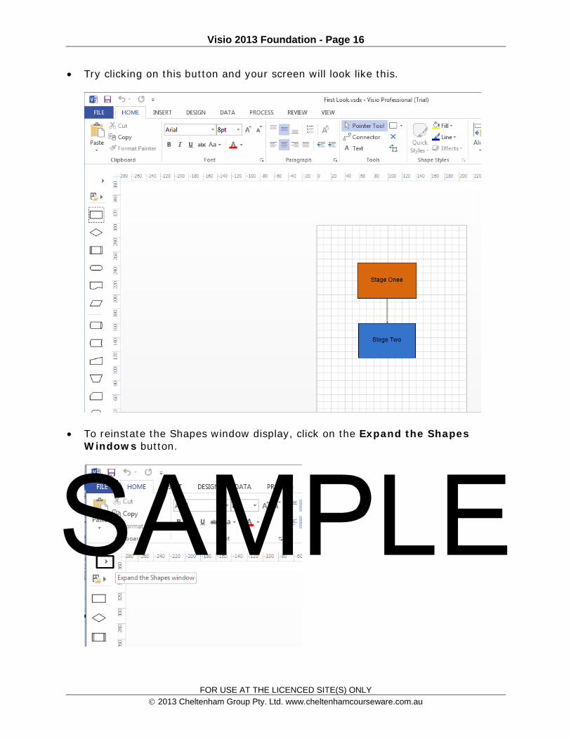
Minimizing the Shapes Window You can click on the Minimize the Shapes window button to allow even more
room on the screen to display the details of your diagram.
SAMPLE
Visio 2013 Foundation - Page 16
FOR USE AT THE LICENCED SITE(S) ONLY 2013 Cheltenham Group Pty. Ltd. www.cheltenhamcourseware.com.au
Try clicking on this button and your screen will look like this.
To reinstate the Shapes window display, click on the Expand the Shapes Windows button.
SAMPLE
Visio 2013 Foundation - Page 17
FOR USE AT THE LICENCED SITE(S) ONLY 2013 Cheltenham Group Pty. Ltd. www.cheltenhamcourseware.com.au
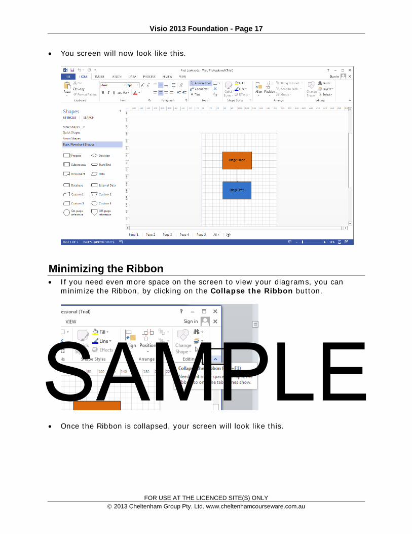
You screen will now look like this.
Minimizing the Ribbon If you need even more space on the screen to view your diagrams, you can
minimize the Ribbon, by clicking on the Collapse the Ribbon button.
Once the Ribbon is collapsed, your screen will look like this.
SAMPLE

Visio 2013 Foundation - Page 18
FOR USE AT THE LICENCED SITE(S) ONLY 2013 Cheltenham Group Pty. Ltd. www.cheltenhamcourseware.com.au
To reinstate the Ribbon, click on one of the tabs (such as Home, Insert etc. and the ribbon will temporally be displayed again. To make the display of the Ribbon permanent again. Click on the Pin the Ribbon control (displayed towards the top-right of your screen).
Rulers A vertical and horizontal ruler are displayed around the edge of the Drawing
Window SAMPLE

Visio 2013 Foundation - Page 19
FOR USE AT THE LICENCED SITE(S) ONLY 2013 Cheltenham Group Pty. Ltd. www.cheltenhamcourseware.com.au
Page Tabs You can have more than one page making up your drawing file. This is very
similar to Excel, where an Excel workbook can contain multiple worksheets. In the example shown, the drawing has five pages.
To move from one page to another page simply click on the tabs. If you are familiar with using Excel the page tabs in Visio can be renamed, copied, moved and deleted in exactly that same ways as you would manipulate them within Excel.
Scroll bars There is normally a horizontal and vertical scroll bar which you can use to move
around within the diagram which is especially useful when you have zoomed in to see detail within the diagram.
SAMPLE

Visio 2013 Foundation - Page 20
FOR USE AT THE LICENCED SITE(S) ONLY 2013 Cheltenham Group Pty. Ltd. www.cheltenhamcourseware.com.au
Visio Status Bar The Visio Status bar is display across the bottom of the Visio screen.
The language used by the diagram is displayed within the Status Bar. For example in the example shown, the language is set to English (United States). Other examples include English (Australia) or English (United Kingdom).
If you select a shape within your diagram, then details about the selected item will be displayed within the Status bar. In the example shown below, the lower shape was selected and you can see information about the width and height of the sample plus the degree of rotation (which is 0 as the shape has not been rotated).
SAMPLE

Visio 2013 Foundation - Page 21
FOR USE AT THE LICENCED SITE(S) ONLY 2013 Cheltenham Group Pty. Ltd. www.cheltenhamcourseware.com.au
Presentation Mode If you click on the Presentation Mode button, within the Status Bar you will see
the diagram display within a special presentation mode display.
Click on this button now and you will see the diagram displayed as illustrated.
Press the Esc key a few times to exit from this special mode.
Zoom Controls You can use the Zoom slider to zoom the view in or out. Try this now.
SAMPLE

Visio 2013 Foundation - Page 22
FOR USE AT THE LICENCED SITE(S) ONLY 2013 Cheltenham Group Pty. Ltd. www.cheltenhamcourseware.com.au
Set the zoom level back to its original value.
Fit Page to Current Window Click on the Fit page to current window control to fit the current page into
the window as displayed on your screen.
Switching between Visio windows If you have multiple copies of Visio running you can use the Switch Windows
control to switch between the various open windows.
Visio Help To get help within Visio press the F1 key. This will display the Visio help screen.
SAMPLE

Visio 2013 Foundation - Page 23
FOR USE AT THE LICENCED SITE(S) ONLY 2013 Cheltenham Group Pty. Ltd. www.cheltenhamcourseware.com.au
Take a few moments to quickly examine what sort of help is available. For instance click on the See What’s New link. SAMPLE

Visio 2013 Foundation - Page 24
FOR USE AT THE LICENCED SITE(S) ONLY 2013 Cheltenham Group Pty. Ltd. www.cheltenhamcourseware.com.au
This will display a page listing all the new features of this version of Visio.
Help Videos Type the word Video into the Help page search box and press the Enter key.
You will see a series of videos listed.
SAMPLE

Visio 2013 Foundation - Page 25
FOR USE AT THE LICENCED SITE(S) ONLY 2013 Cheltenham Group Pty. Ltd. www.cheltenhamcourseware.com.au
Click on any one of these videos and watch the video. This is an easy way of leaning more about Visio.
Close the Visio program. SAMPLE

Visio 2013 Foundation - Page 26
FOR USE AT THE LICENCED SITE(S) ONLY 2013 Cheltenham Group Pty. Ltd. www.cheltenhamcourseware.com.au
Using Templates
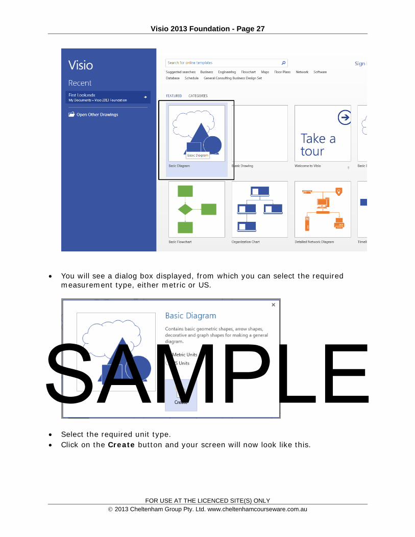
Creating a new diagram based on the Blank Diagram Template Start Visio. The starting screen will look similar to the illustration below.
Scroll down and you will see a number of commonly used Visio templates displayed.
Click on the Basic Diagram template.
SAMPLE
Visio 2013 Foundation - Page 27
FOR USE AT THE LICENCED SITE(S) ONLY 2013 Cheltenham Group Pty. Ltd. www.cheltenhamcourseware.com.au
You will see a dialog box displayed, from which you can select the required measurement type, either metric or US.
Select the required unit type. Click on the Create button and your screen will now look like this.
SAMPLE

Visio 2013 Foundation - Page 28
FOR USE AT THE LICENCED SITE(S) ONLY 2013 Cheltenham Group Pty. Ltd. www.cheltenhamcourseware.com.au
As you can see you now have the tools available to create a new diagram from scratch.
Press Alt+F4 to close the Visio program.
Using a different template Start Visio and from the opening screen select Home Plan.
SAMPLE

Visio 2013 Foundation - Page 29
FOR USE AT THE LICENCED SITE(S) ONLY 2013 Cheltenham Group Pty. Ltd. www.cheltenhamcourseware.com.au
Select the unit type.
If you look carefully, you will see that the masters all relate to House Plans. SAMPLE
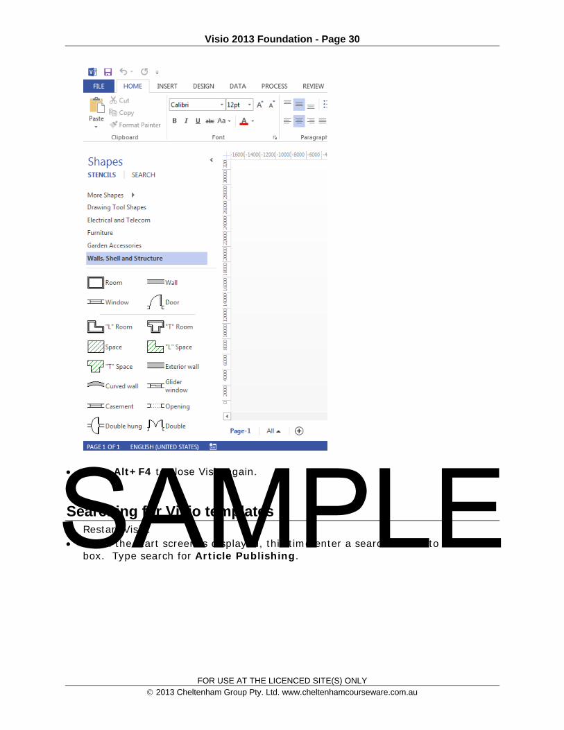
Visio 2013 Foundation - Page 30
FOR USE AT THE LICENCED SITE(S) ONLY 2013 Cheltenham Group Pty. Ltd. www.cheltenhamcourseware.com.au
Press Alt+F4 to close Visio again.
Searching for Visio templates Restart Visio. When the start screen is displayed, this time enter a search term into the search
box. Type search for Article Publishing.
SAMPLE

Visio 2013 Foundation - Page 31
FOR USE AT THE LICENCED SITE(S) ONLY 2013 Cheltenham Group Pty. Ltd. www.cheltenhamcourseware.com.au
You should see the following displayed.
Click on this template and you will see the following. SAMPLE

Visio 2013 Foundation - Page 32
FOR USE AT THE LICENCED SITE(S) ONLY 2013 Cheltenham Group Pty. Ltd. www.cheltenhamcourseware.com.au
Click on the Create button and the template will be downloaded to your computer. Once downloaded your screen will look like this.
If you look in detail at the diagram you will see the following.
SAMPLE

Visio 2013 Foundation - Page 33
FOR USE AT THE LICENCED SITE(S) ONLY 2013 Cheltenham Group Pty. Ltd. www.cheltenhamcourseware.com.au
As you can see in this case the template also created content for you which you can modify to suite your particular needs.
Press Alt+F4 to close Visio.
SAMPLE

Visio 2013 Foundation - Page 34
FOR USE AT THE LICENCED SITE(S) ONLY 2013 Cheltenham Group Pty. Ltd. www.cheltenhamcourseware.com.au
Shapes and Connectors
Adding shapes to the drawing area To add a shape to the drawing simply click and drag a shape from the shapes
pane to your drawing area. In this case move the mouse pointer over the Rectangle shape master.
Depress the left mouse button and while keeping it depressed, drag the Rectangle shape into the current drawing page. Release the mouse button and your screen should now look like this. SAMPLE
Visio 2013 Foundation - Page 35
FOR USE AT THE LICENCED SITE(S) ONLY 2013 Cheltenham Group Pty. Ltd. www.cheltenhamcourseware.com.au
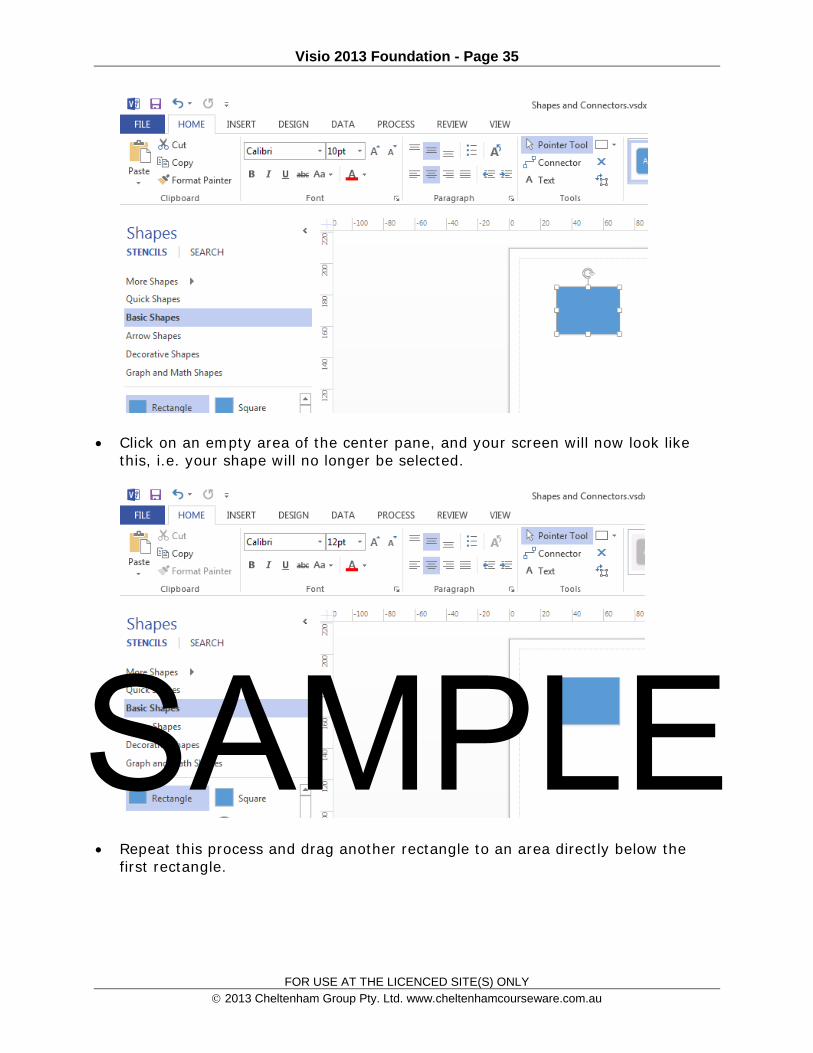
Click on an empty area of the center pane, and your screen will now look like this, i.e. your shape will no longer be selected.
Repeat this process and drag another rectangle to an area directly below the first rectangle.
SAMPLE
Visio 2013 Foundation - Page 36
FOR USE AT THE LICENCED SITE(S) ONLY 2013 Cheltenham Group Pty. Ltd. www.cheltenhamcourseware.com.au
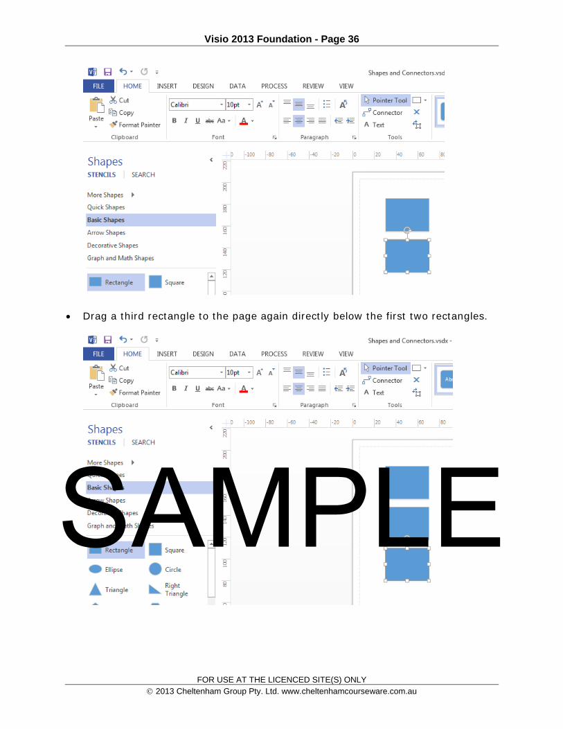
Drag a third rectangle to the page again directly below the first two rectangles.
SAMPLE

Visio 2013 Foundation - Page 37
FOR USE AT THE LICENCED SITE(S) ONLY 2013 Cheltenham Group Pty. Ltd. www.cheltenhamcourseware.com.au
The Connector tool Click on the Connector button.
Click on the top shape and then drag down to the second shape. A connector will be inserted from the first shape to the second shape.
Repeat the process so that a connector is inserted from the second shape to the third shape.
The Pointer Tool Currently the mouse pointer is in ‘connector’ mode. To switch back to the
default ‘pointer’ mode, click on the Pointer Tool button.
SAMPLE

Visio 2013 Foundation - Page 38
FOR USE AT THE LICENCED SITE(S) ONLY 2013 Cheltenham Group Pty. Ltd. www.cheltenhamcourseware.com.au
Inserting a different shape Within the Shapes windows, scroll down and select the Diamond shape. The
diamond shape is often used in diagrams to indicate yes/no type decisions.
Click on the Connector button again and add a connector from the third rectangle to the diamond shape.
Also add connectors from the diamond shape to the last two rectangles you inserted into the diagram. SAMPLE

Visio 2013 Foundation - Page 39
FOR USE AT THE LICENCED SITE(S) ONLY 2013 Cheltenham Group Pty. Ltd. www.cheltenhamcourseware.com.au
Adding text to the shape So far we have created a very basic flow chart, but without any text within the
shapes, it is meaningless. To add text to the shape, double click on the shape and type your text. In this case, select the top shape, and double click on it. You will notice that the shape is zoomed to make it easier to see. Type in the text Specify Content, as illustrated below.
SAMPLE

Visio 2013 Foundation - Page 40
FOR USE AT THE LICENCED SITE(S) ONLY 2013 Cheltenham Group Pty. Ltd. www.cheltenhamcourseware.com.au
Double click on the next shape down and enter the text Draft Copy.
Carry on adding the following text. Technical Proof Technical Proof OK? Fix Errors Publish Article
Your page will now look like this.
SAMPLE
Visio 2013 Foundation - Page 41
FOR USE AT THE LICENCED SITE(S) ONLY 2013 Cheltenham Group Pty. Ltd. www.cheltenhamcourseware.com.au
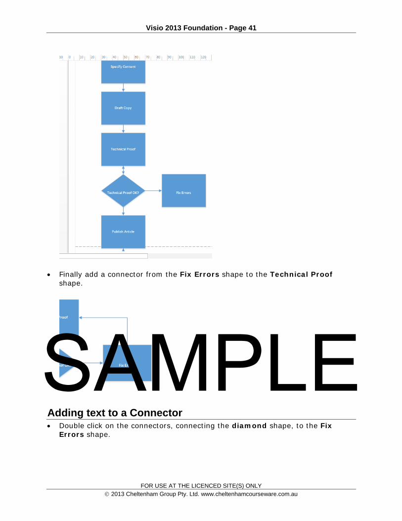
Finally add a connector from the Fix Errors shape to the Technical Proof shape.
Adding text to a Connector Double click on the connectors, connecting the diamond shape, to the Fix
Errors shape.
SAMPLE

Visio 2013 Foundation - Page 42
FOR USE AT THE LICENCED SITE(S) ONLY 2013 Cheltenham Group Pty. Ltd. www.cheltenhamcourseware.com.au
A box will be displayed within the connector. Type in the word No.
Double click on the connector leading from the diamond shape to the Publish Article shape. Type in the word Yes.
The diagram will now look like this.
Deleting a Connector To delete a connector, first click on the connector to select it and then press the
Del key. Try deleting other connectors within your diagram. Press the Undo button to restore the deleted connectors.
Moving shapes Click on the Pointer Tool button.
SAMPLE

Visio 2013 Foundation - Page 43
FOR USE AT THE LICENCED SITE(S) ONLY 2013 Cheltenham Group Pty. Ltd. www.cheltenhamcourseware.com.au
To move a shape, click on the shape and drag it to where you want it to move. Experiment with moving some of the shapes.
Resizing shapes To resize a shape, click on the shape to select it, and then drag the shape from
the corners to resize it.
Deleting shapes To delete a shape, click on the shape to select it and then press the Del key.
Experiment with deleting some of the shapes.
Save your changes and close the diagram file. SAMPLE
Visio 2013 Foundation - Page 44
FOR USE AT THE LICENCED SITE(S) ONLY 2013 Cheltenham Group Pty. Ltd. www.cheltenhamcourseware.com.au
Backgrounds, Borders, Titles & Themes
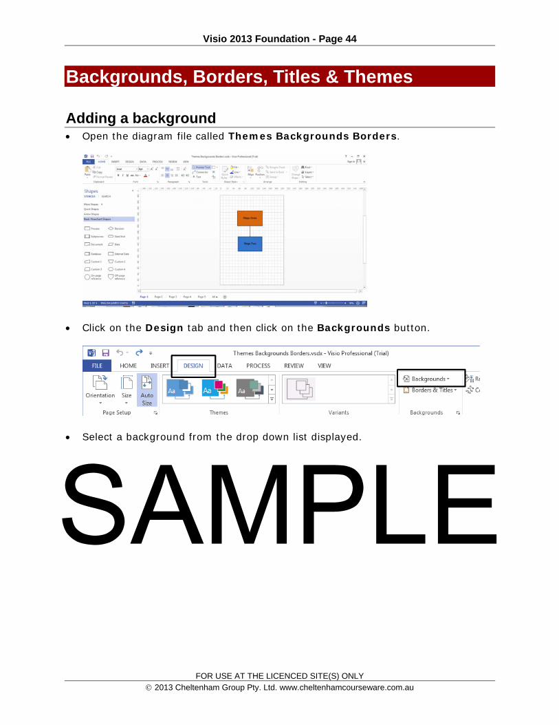
Adding a background Open the diagram file called Themes Backgrounds Borders.
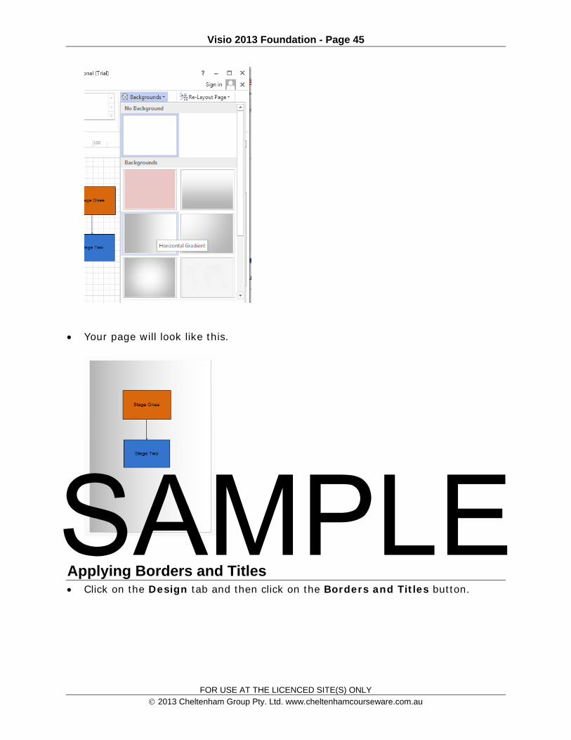
Click on the Design tab and then click on the Backgrounds button.
Select a background from the drop down list displayed.
SAMPLE
Visio 2013 Foundation - Page 45
FOR USE AT THE LICENCED SITE(S) ONLY 2013 Cheltenham Group Pty. Ltd. www.cheltenhamcourseware.com.au
Your page will look like this.
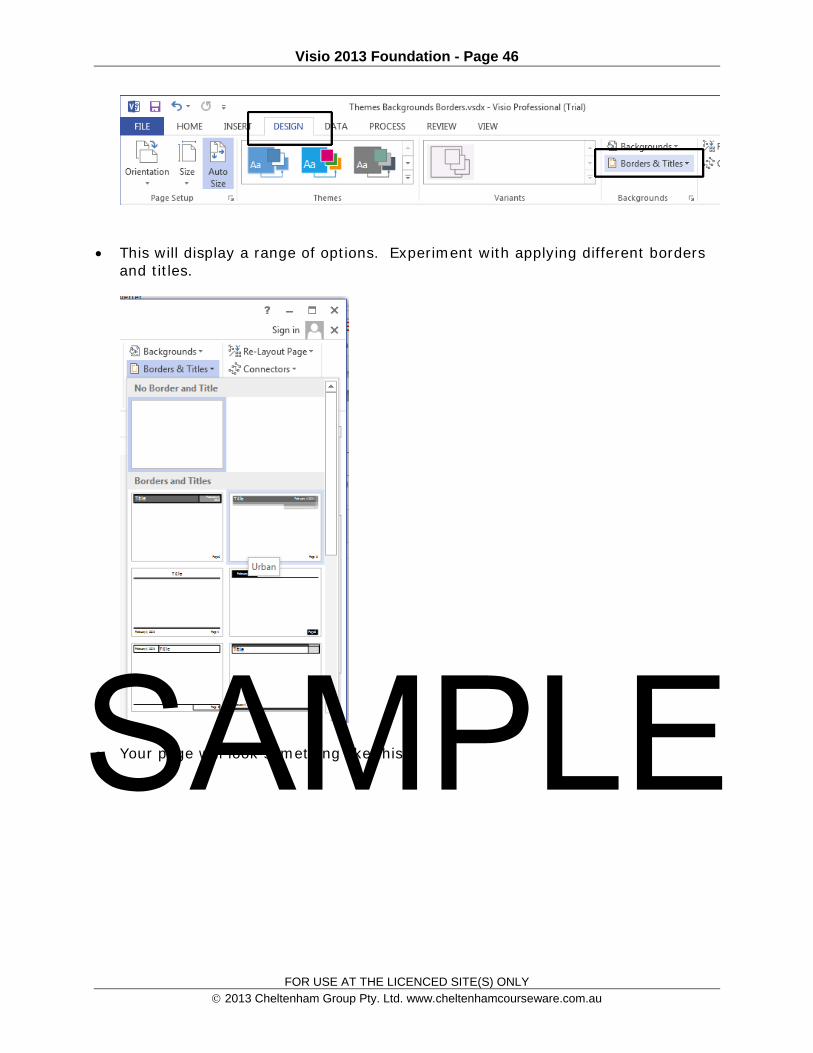
Applying Borders and Titles Click on the Design tab and then click on the Borders and Titles button.
SAMPLE
Visio 2013 Foundation - Page 46
FOR USE AT THE LICENCED SITE(S) ONLY 2013 Cheltenham Group Pty. Ltd. www.cheltenhamcourseware.com.au
This will display a range of options. Experiment with applying different borders and titles.
Your page will look something like this. SAMPLE

Visio 2013 Foundation - Page 47
FOR USE AT THE LICENCED SITE(S) ONLY 2013 Cheltenham Group Pty. Ltd. www.cheltenhamcourseware.com.au
Applying Design Themes Click on the Design tab and then click on a theme within the Ribbon.
You can use the drop down control to display more themes. SAMPLE

Visio 2013 Foundation - Page 48
FOR USE AT THE LICENCED SITE(S) ONLY 2013 Cheltenham Group Pty. Ltd. www.cheltenhamcourseware.com.au
The example below shows the effect of applying a theme.
You can also use the Theme Variants section to customize your effects.
SAMPLE

Visio 2013 Foundation - Page 49
FOR USE AT THE LICENCED SITE(S) ONLY 2013 Cheltenham Group Pty. Ltd. www.cheltenhamcourseware.com.au
Click on the More button in the Variants section to display a drop down allowing even more choices.
Your choices include Colors, Effects, Connections and Embellishments.
Save your changes and close the diagram file. Close the Visio program.
SAMPLE

Visio 2013 Foundation - Page 50
FOR USE AT THE LICENCED SITE(S) ONLY 2013 Cheltenham Group Pty. Ltd. www.cheltenhamcourseware.com.au
SAMPLE
Visio 2013 Foundation - Page 51
FOR USE AT THE LICENCED SITE(S) ONLY 2013 Cheltenham Group Pty. Ltd. www.cheltenhamcourseware.com.au
Formatting Text & Shapes
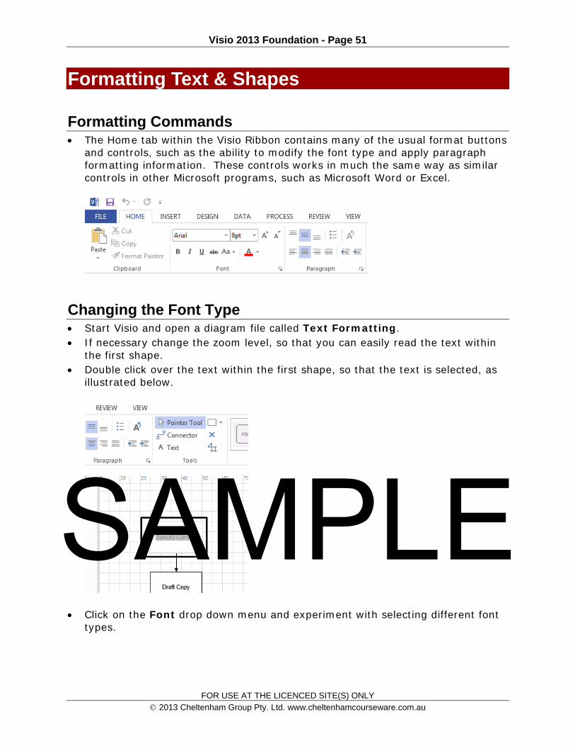
Formatting Commands The Home tab within the Visio Ribbon contains many of the usual format buttons
and controls, such as the ability to modify the font type and apply paragraph formatting information. These controls works in much the same way as similar controls in other Microsoft programs, such as Microsoft Word or Excel.
Changing the Font Type Start Visio and open a diagram file called Text Formatting. If necessary change the zoom level, so that you can easily read the text within
the first shape. Double click over the text within the first shape, so that the text is selected, as
illustrated below.
Click on the Font drop down menu and experiment with selecting different font types.
SAMPLE

Visio 2013 Foundation - Page 52
FOR USE AT THE LICENCED SITE(S) ONLY 2013 Cheltenham Group Pty. Ltd. www.cheltenhamcourseware.com.au
This will change the font of the selected text.
Font Size Select the text within the first shape. Click on the down arrow next to the Font
Size drop down menu and experiment with applying different font sizes.
SAMPLE

Visio 2013 Foundation - Page 53
FOR USE AT THE LICENCED SITE(S) ONLY 2013 Cheltenham Group Pty. Ltd. www.cheltenhamcourseware.com.au
Reset the font size to a more useful size before continuing.
Font Style, Bold, Italic and Underline Select the text within the first shape and experiment with clicking on the Bold,
Italic, and Underline buttons.
Font Color Select the text within the first shape. Experiment with applying different font
colors, by clicking on the down arrow next to the Font Color drop down menu, and selecting a color. SAMPLE

Visio 2013 Foundation - Page 54
FOR USE AT THE LICENCED SITE(S) ONLY 2013 Cheltenham Group Pty. Ltd. www.cheltenhamcourseware.com.au
Font Case Select the text within the first shape. Click on the Change Case drop down
arrow and experiment with applying different types of font case, such as All Caps.
More Font formatting options Click on the More button within the Font section of the Ribbon.
SAMPLE

Visio 2013 Foundation - Page 55
FOR USE AT THE LICENCED SITE(S) ONLY 2013 Cheltenham Group Pty. Ltd. www.cheltenhamcourseware.com.au
This will display the Text dialog box, from which you can apply further font formatting options.
Experiment with applying different types of underlining and also strike through effects.
Also experiment with adjusting the transparency percentage of the font.
More Paragraph formatting options Click on the More button within the Paragraph section of the Ribbon.
SAMPLE
Visio 2013 Foundation - Page 56
FOR USE AT THE LICENCED SITE(S) ONLY 2013 Cheltenham Group Pty. Ltd. www.cheltenhamcourseware.com.au
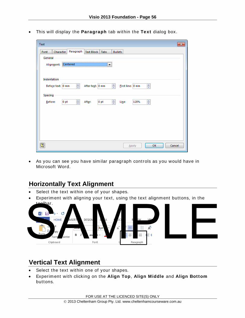
This will display the Paragraph tab within the Text dialog box.
As you can see you have similar paragraph controls as you would have in Microsoft Word.
Horizontally Text Alignment Select the text within one of your shapes. Experiment with aligning your text, using the text alignment buttons, in the
toolbar.
Vertical Text Alignment Select the text within one of your shapes. Experiment with clicking on the Align Top, Align Middle and Align Bottom
buttons.
SAMPLE

Visio 2013 Foundation - Page 57
FOR USE AT THE LICENCED SITE(S) ONLY 2013 Cheltenham Group Pty. Ltd. www.cheltenhamcourseware.com.au
Changing the Line Indent Select the text within one of your shapes. Experiment with clicking on the Decrease Indent or Increase Indent buttons
in the toolbar.
Text Rotation Select the text within one of your shapes. Click on the Rotate Text button in the toolbar.
See what happens when you repeatedly click on this button.
Bullets Select the text within one of your shapes.
SAMPLE

Visio 2013 Foundation - Page 58
FOR USE AT THE LICENCED SITE(S) ONLY 2013 Cheltenham Group Pty. Ltd. www.cheltenhamcourseware.com.au
Click on the Bullets button in the toolbar.
Save your changes and close the file.
SAMPLE
Visio 2013 Foundation - Page 59
FOR USE AT THE LICENCED SITE(S) ONLY 2013 Cheltenham Group Pty. Ltd. www.cheltenhamcourseware.com.au
Formatting Shapes
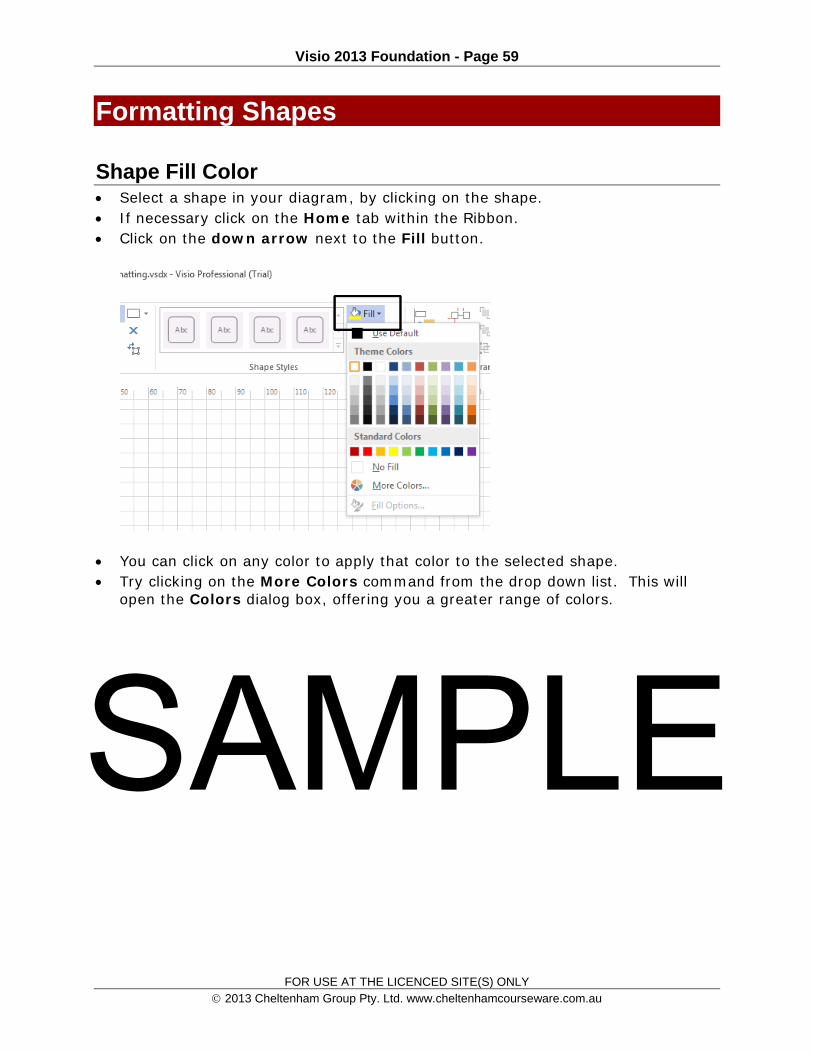
Shape Fill Color Select a shape in your diagram, by clicking on the shape. If necessary click on the Home tab within the Ribbon. Click on the down arrow next to the Fill button.
You can click on any color to apply that color to the selected shape. Try clicking on the More Colors command from the drop down list. This will
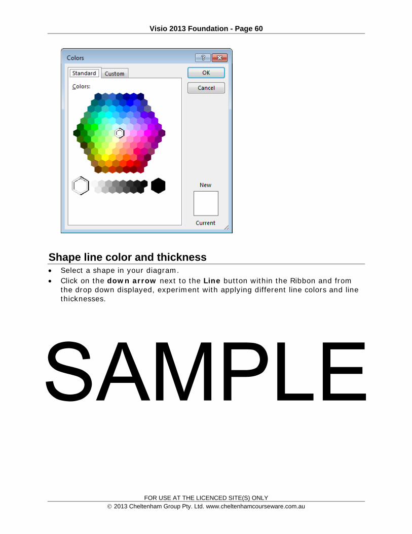
open the Colors dialog box, offering you a greater range of colors.
SAMPLE
Visio 2013 Foundation - Page 60
FOR USE AT THE LICENCED SITE(S) ONLY 2013 Cheltenham Group Pty. Ltd. www.cheltenhamcourseware.com.au
Shape line color and thickness Select a shape in your diagram. Click on the down arrow next to the Line button within the Ribbon and from
the drop down displayed, experiment with applying different line colors and line thicknesses.
SAMPLE

Visio 2013 Foundation - Page 61
FOR USE AT THE LICENCED SITE(S) ONLY 2013 Cheltenham Group Pty. Ltd. www.cheltenhamcourseware.com.au
Shape Effects Select a shape in your diagram, by clicking on the shape. Click on the down arrow next to the Effects button and investigate the many
Effect options. SAMPLE

Visio 2013 Foundation - Page 62
FOR USE AT THE LICENCED SITE(S) ONLY 2013 Cheltenham Group Pty. Ltd. www.cheltenhamcourseware.com.au
The example below shows a rectangle shape which has had a 3-D Rotation effects applied to it.
Modifying Connection Arrows Select a connector between two shapes within your diagram.
SAMPLE

Visio 2013 Foundation - Page 63
FOR USE AT THE LICENCED SITE(S) ONLY 2013 Cheltenham Group Pty. Ltd. www.cheltenhamcourseware.com.au
Click on the down arrow next to the Line button within the Ribbon. From the drop down list displayed select Arrows.
Experiment with applying different arrow styles to the connectors.
Rounding Shape Corners Select a shape in your diagram, by clicking on the shape.
Click on the down arrow next to the Line button within the Ribbon. SAMPLE

Visio 2013 Foundation - Page 64
FOR USE AT THE LICENCED SITE(S) ONLY 2013 Cheltenham Group Pty. Ltd. www.cheltenhamcourseware.com.au
From the drop down list displayed select the Line Options command. This will display the Format Shape pane to the right of the screen.
You will notice that be default the Rounding Size is 0. Use a larger value and experiment with the effect produced.
SAMPLE

Visio 2013 Foundation - Page 65
FOR USE AT THE LICENCED SITE(S) ONLY 2013 Cheltenham Group Pty. Ltd. www.cheltenhamcourseware.com.au
You can also modify the Rounding Preset Type.
Save your changes and close the Visio program.
SAMPLE

Visio 2013 Foundation - Page 66
FOR USE AT THE LICENCED SITE(S) ONLY 2013 Cheltenham Group Pty. Ltd. www.cheltenhamcourseware.com.au
Manipulating Shapes
Grouping shapes Grouping shapes is used to group multiple shapes together, so that these
grouped shapes act as a single object. When two or more shapes are grouped together, making changes to one shape such as resizing or moving etc. will also apply the same changes to the other shapes that are grouped together.
Open the Visio program and open a diagram file called Managing shapes. If necessary change to Page 1 of the diagram.
Page one of this file contains three shapes.
Try dragging the top shape to a new location on your work area. You will find that when you do this, just the selected shape moves, as you would expect. Click on the Undo button to reset the position of the shape.
Press and hold the Shift key on your keyboard. Click on each shape. All three shapes will now be selected, as illustrated below. Release the Shift key. SAMPLE

Visio 2013 Foundation - Page 67
FOR USE AT THE LICENCED SITE(S) ONLY 2013 Cheltenham Group Pty. Ltd. www.cheltenhamcourseware.com.au
Click on the Group button within the Home tab on the Ribbon.
From the drop down displayed, select Group.
This will group all the selected shapes together. SAMPLE

Visio 2013 Foundation - Page 68
FOR USE AT THE LICENCED SITE(S) ONLY 2013 Cheltenham Group Pty. Ltd. www.cheltenhamcourseware.com.au
Click on an empty part of the working area, so that the shapes are no longer selected.
Try selecting one of the shapes and you will find that when you drag to a new position, all three shapes act as a single item, and all three are dragged to the new position.
Ungrouping shapes Display page 2, by clicking on the Page-2 tab at the bottom-left of the screen.
This will display a page with three, grouped shapes, on it. Try moving one shape, and because they are grouped, they will all move.
Click on the Home tab within the Ribbon and then click on the Group button. From the drop down menu displayed click on the Ungroup command.
SAMPLE

Visio 2013 Foundation - Page 69
FOR USE AT THE LICENCED SITE(S) ONLY 2013 Cheltenham Group Pty. Ltd. www.cheltenhamcourseware.com.au
Your screen will now look like this.
Click on an empty part of the working area, so that the shapes are no longer selected. Try dragging each of the shapes in turn to a different position on the screen. You should find that all three shapes can now be moved independently.
Ordering shapes Ordering shapes is useful when you have multiple shapes on your drawing page
and you want to bring some shapes to the front, and some to the background.
Bringing a shape to the front Display page 3, by clicking on the Page-3 tab, at the bottom-left of the screen.
This page contains the following layered shapes. The diamond shape is at the top layer, the rectangle is at the middle layer and the cylinder is at the bottom of the layer stack.
SAMPLE
Visio 2013 Foundation - Page 70
FOR USE AT THE LICENCED SITE(S) ONLY 2013 Cheltenham Group Pty. Ltd. www.cheltenhamcourseware.com.au
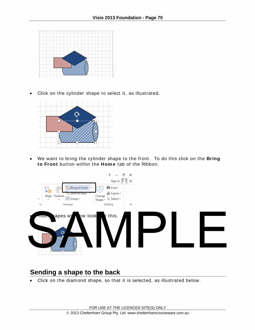
Click on the cylinder shape to select it, as illustrated.
We want to bring the cylinder shape to the front. To do this click on the Bring to Front button within the Home tab of the Ribbon.
Your shapes will now look like this.
Sending a shape to the back Click on the diamond shape, so that it is selected, as illustrated below.
SAMPLE
Visio 2013 Foundation - Page 71
FOR USE AT THE LICENCED SITE(S) ONLY 2013 Cheltenham Group Pty. Ltd. www.cheltenhamcourseware.com.au
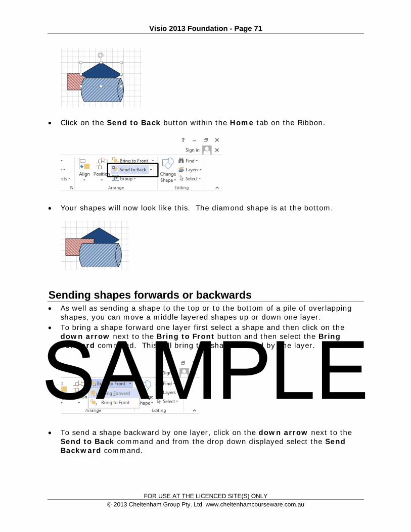
Click on the Send to Back button within the Home tab on the Ribbon.
Your shapes will now look like this. The diamond shape is at the bottom.
Sending shapes forwards or backwards As well as sending a shape to the top or to the bottom of a pile of overlapping
shapes, you can move a middle layered shapes up or down one layer. To bring a shape forward one layer first select a shape and then click on the
down arrow next to the Bring to Front button and then select the Bring Forward command. This will bring the shape forward by one layer.
To send a shape backward by one layer, click on the down arrow next to the Send to Back command and from the drop down displayed select the Send Backward command.
SAMPLE

Visio 2013 Foundation - Page 72
FOR USE AT THE LICENCED SITE(S) ONLY 2013 Cheltenham Group Pty. Ltd. www.cheltenhamcourseware.com.au
Rotating a shape to the left or right Display page 4, by clicking on the Page-4 tab, at the bottom-left of the screen.
Select the top shape on the page. Click on the Position button on the Home tab in the Ruler.
From the drop down menu displayed click on the Rotate Shape command. From the submenu displayed, select either Rotate Right 90 degrees or Rotate Left 90 degrees. SAMPLE

Visio 2013 Foundation - Page 73
FOR USE AT THE LICENCED SITE(S) ONLY 2013 Cheltenham Group Pty. Ltd. www.cheltenhamcourseware.com.au
Free rotating a shape Click on the Pointer button within the Standard Toolbar. Click and select a shape that you want to rotate. Move your mouse over the point that appears like a small circle. You will notice
that your mouse pointer has changed to a rotating circle.
Press and hold the left mouse button and move your mouse to the left or to the right. This will rotate the shape. Release the mouse button when your shape is rotated to the desired angle.
SAMPLE

Visio 2013 Foundation - Page 74
FOR USE AT THE LICENCED SITE(S) ONLY 2013 Cheltenham Group Pty. Ltd. www.cheltenhamcourseware.com.au
Rotating text within a shape Display page 5, by clicking on the Page-5 tab, at the bottom-left of the screen.
Click on the top shape to select it. Click on the Rotate Text button, within the Home tab on the Ribbon.
This will rotate the text in the selected shape by 90-degrees.
Experiment with rotating the text in the other two shapes.
Flipping a shape horizontally and vertically Display page 6, by clicking on the Page-6 tab, at the bottom-left of the screen.
Click and select the top shape. Click on the Position button within the Home tab of the Ribbon. From the drop down menu displayed click on Rotate Shapes.
SAMPLE

Visio 2013 Foundation - Page 75
FOR USE AT THE LICENCED SITE(S) ONLY 2013 Cheltenham Group Pty. Ltd. www.cheltenhamcourseware.com.au
From the submenu displayed click on one of the Flip options.
Aligning shapes vertically and horizontally Multiple shapes can be aligned, vertically or horizontally.
Display page 7, by clicking on the Page-7 tab, at the bottom-left of the screen.
First we will vertically align the 3 shapes at the top of the page. Click on the
first, top, rectangle shape, and while pressing the Shift key, click on the other two rectangle shapes. The top three shapes will now be selected.
Click on the Align button within the Ribbon (under the Home tab). From the drop down menu select the required alignment command.
SAMPLE

Visio 2013 Foundation - Page 76
FOR USE AT THE LICENCED SITE(S) ONLY 2013 Cheltenham Group Pty. Ltd. www.cheltenhamcourseware.com.au
The three shapes are now aligned, as illustrated above.
Now we will horizontally align the three diamond shapes. First select all three diamond shapes.
Then click on the Align button and from the drop down menu displayed select the required alignment option. SAMPLE

Visio 2013 Foundation - Page 77
FOR USE AT THE LICENCED SITE(S) ONLY 2013 Cheltenham Group Pty. Ltd. www.cheltenhamcourseware.com.au
The diamond shapes will now be aligned, as illustrated below.
Distributing shapes Three or more shapes can be distributed, so that the interval or space between
them becomes uniform.
Display page 8, by clicking on the Page-8 tab, at the bottom-left of the screen. SAMPLE

Visio 2013 Foundation - Page 78
FOR USE AT THE LICENCED SITE(S) ONLY 2013 Cheltenham Group Pty. Ltd. www.cheltenhamcourseware.com.au
First we will change the horizontal distribution of the three rectangular shapes. First select the three rectangular shapes.
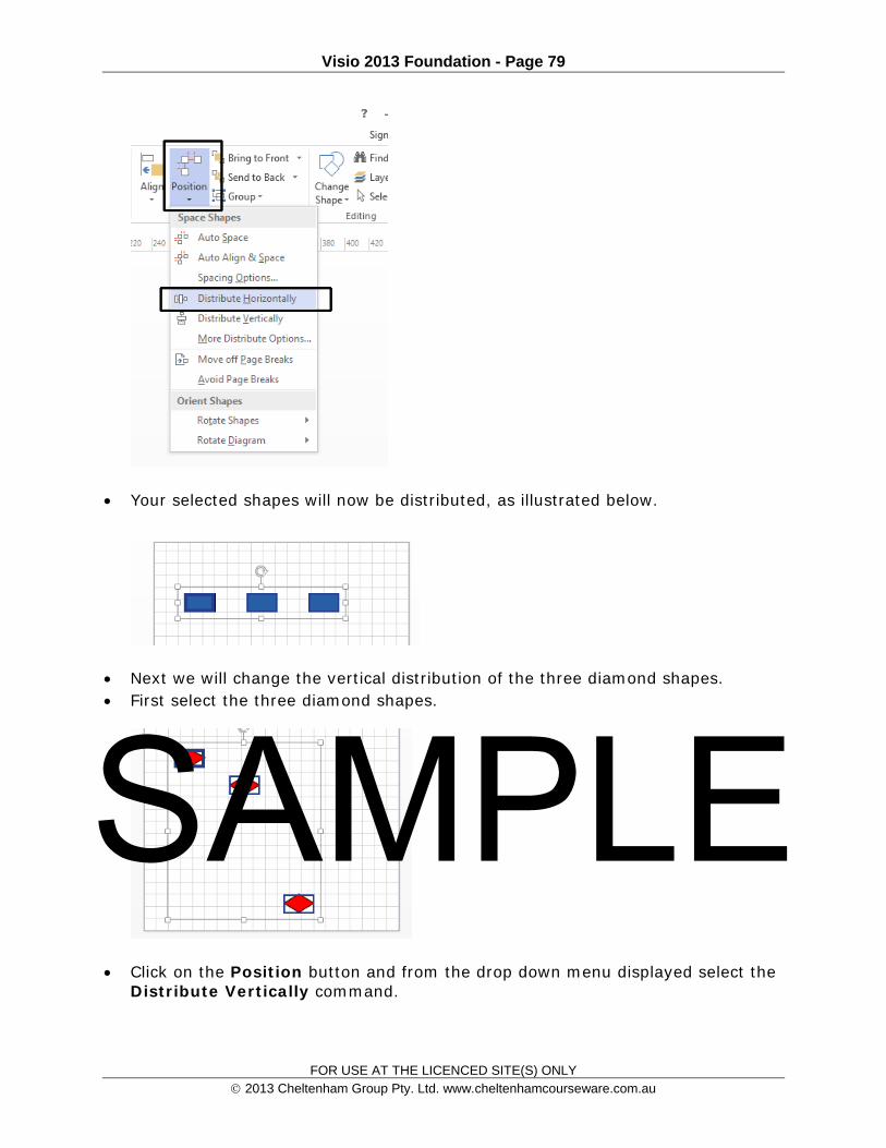
Click on the Position button and from the drop down menu displayed select the Distribute Horizontally command.
SAMPLE
Visio 2013 Foundation - Page 79
FOR USE AT THE LICENCED SITE(S) ONLY 2013 Cheltenham Group Pty. Ltd. www.cheltenhamcourseware.com.au
Your selected shapes will now be distributed, as illustrated below.
Next we will change the vertical distribution of the three diamond shapes. First select the three diamond shapes.
Click on the Position button and from the drop down menu displayed select the Distribute Vertically command.
SAMPLE

Visio 2013 Foundation - Page 80
FOR USE AT THE LICENCED SITE(S) ONLY 2013 Cheltenham Group Pty. Ltd. www.cheltenhamcourseware.com.au
An example is illustrated below.
Adjusting shape layout Display page 9, by clicking on the Page-9 tab, at the bottom-left of the screen.
If necessary, adjust the zoom level so that you can read the text within the shapes. SAMPLE
Visio 2013 Foundation - Page 81
FOR USE AT THE LICENCED SITE(S) ONLY 2013 Cheltenham Group Pty. Ltd. www.cheltenhamcourseware.com.au
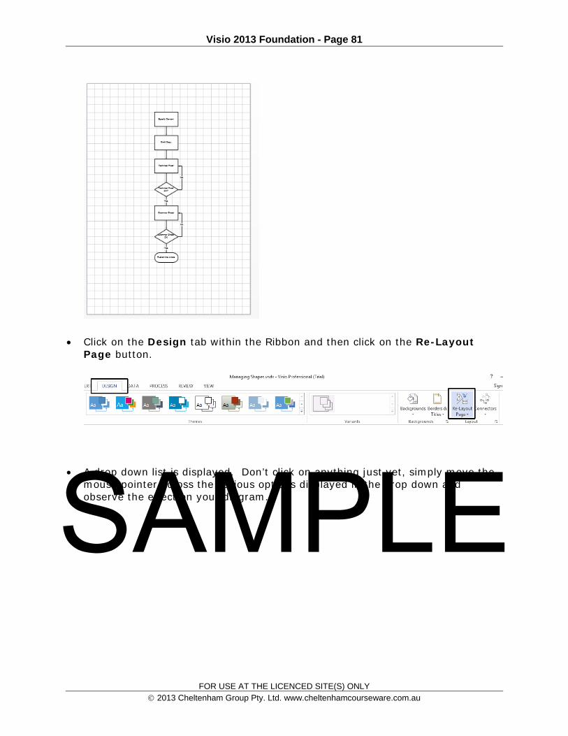
Click on the Design tab within the Ribbon and then click on the Re-Layout
Page button.
A drop down list is displayed. Don’t click on anything just yet, simply move the mouse pointer across the various options displayed in the drop down and observe the effect on your diagram. SAMPLE
Visio 2013 Foundation - Page 82
FOR USE AT THE LICENCED SITE(S) ONLY 2013 Cheltenham Group Pty. Ltd. www.cheltenhamcourseware.com.au
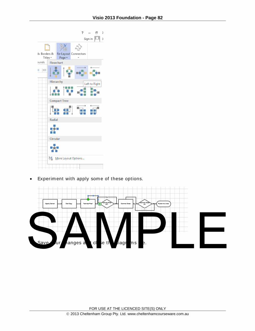
Experiment with apply some of these options.
Save your changes and close the diagrams file. SAMPLE

Visio 2013 Foundation - Page 83
FOR USE AT THE LICENCED SITE(S) ONLY 2013 Cheltenham Group Pty. Ltd. www.cheltenhamcourseware.com.au
Formatting Connectors
Using curved connectors Open a diagram called Formatting Connectors. Make sure that Page 1 is displayed.
Click on the connector between Stage One and Stage Two.
Click on the Design tab in the Ribbon and then click on the Connections button.
From the drop down menus displayed, select the Curved Lines command.
The connector will now look like this.
SAMPLE

Visio 2013 Foundation - Page 84
FOR USE AT THE LICENCED SITE(S) ONLY 2013 Cheltenham Group Pty. Ltd. www.cheltenhamcourseware.com.au
Using straight connectors Click on a connector between Stage One and Stage Two. Click on the Design tab in the Ribbon and then click on the Connections
button.
From the drop down menus displayed, select the Straight Line command.
The connector will now look like this.
SAMPLE
Visio 2013 Foundation - Page 85
FOR USE AT THE LICENCED SITE(S) ONLY 2013 Cheltenham Group Pty. Ltd. www.cheltenhamcourseware.com.au
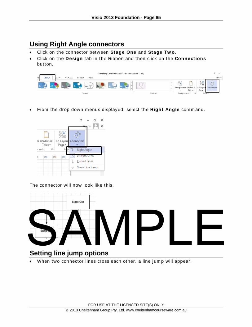
Using Right Angle connectors Click on the connector between Stage One and Stage Two. Click on the Design tab in the Ribbon and then click on the Connections
button.
From the drop down menus displayed, select the Right Angle command.
The connector will now look like this.
Setting line jump options When two connector lines cross each other, a line jump will appear.
SAMPLE

Visio 2013 Foundation - Page 86
FOR USE AT THE LICENCED SITE(S) ONLY 2013 Cheltenham Group Pty. Ltd. www.cheltenhamcourseware.com.au
Display page 2, by clicking on the Page-2 tab, at the bottom-left of the screen. Click on a connector line that connects the Technical Proof OK diamond to the
Technical Proof rectangle.
Click on the Design tab in the Ribbon and then click on the Connections button.
Within the drop down menu displayed you will notice that the Show Line Jump option is ticked.
Try un-ticking this option and you will see that line jumps are no longer displayed within the diagram.
Reinstate the line jumps before continuing. Save your changes and close the Visio program.
SAMPLE

Visio 2013 Foundation - Page 87
FOR USE AT THE LICENCED SITE(S) ONLY 2013 Cheltenham Group Pty. Ltd. www.cheltenhamcourseware.com.au
SAMPLE

Visio 2013 Foundation - Page 88
FOR USE AT THE LICENCED SITE(S) ONLY 2013 Cheltenham Group Pty. Ltd. www.cheltenhamcourseware.com.au
Using Snap and Glue
Snapping and gluing Snapping: The snapping settings determine how shapes are placed on the
Drawing page, in relation to other elements such as Grid, Guides and Rulers. Gluing: The gluing settings determine which elements of a shape are used to glue connectors.
Displaying the Snap and Glue Dialog Box Open the Visio program and open a file called Snap and Glue.
Click on the View tab and then click on the More button within the Visual Aids
section of the Ribbon.
This will display the Snap and Glue dialog box.
SAMPLE

Visio 2013 Foundation - Page 89
FOR USE AT THE LICENCED SITE(S) ONLY 2013 Cheltenham Group Pty. Ltd. www.cheltenhamcourseware.com.au
As you can see in the example above both Snap and Glue are active (they are both ticked). Examine some of the Snap options and also the Glue options.
Using Glue to Shape When connected with Dynamic Glue, the connectors adjust automatically when
moving the shapes, and reposition to the closest point between the two shapes.
To connect the two top shapes with Dynamic Glue, click on the Home tab and then click on the Connector button.
Move your cursor over the first Shape and then click and press the left mouse button. While keeping the mouse button pressed, move your mouse over the second shape.
Now release the mouse. It will connect the two shapes with Dynamic Glue.
Click on the Pointer Tool within the Ribbon.
Move one of the shapes and you will notice that the connector will reposition itself on the shape.
SAMPLE

Visio 2013 Foundation - Page 90
FOR USE AT THE LICENCED SITE(S) ONLY 2013 Cheltenham Group Pty. Ltd. www.cheltenhamcourseware.com.au
Using Glue to Connection Point Static Glue is also known as Point-to-Point Glue. It connects two shapes to
specific points. When connected with Static Glue, the connectors stay connected to the original points when the shapes are moved.
Click on the Home tab and then click on the Connector button.
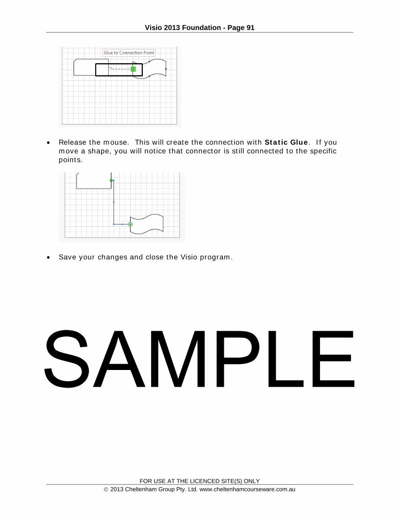
Move your cursor over a point on the bottom-left Shape until you see a green color box appear around the point.
Click on it and drag it to a specific point on the second shape until you see a green color box appear around the point.
SAMPLE
Visio 2013 Foundation - Page 91
FOR USE AT THE LICENCED SITE(S) ONLY 2013 Cheltenham Group Pty. Ltd. www.cheltenhamcourseware.com.au
Release the mouse. This will create the connection with Static Glue. If you move a shape, you will notice that connector is still connected to the specific points.
Save your changes and close the Visio program.
SAMPLE
Visio 2013 Foundation - Page 92
FOR USE AT THE LICENCED SITE(S) ONLY 2013 Cheltenham Group Pty. Ltd. www.cheltenhamcourseware.com.au
Using Layers
Layers Layers are used to organize related shapes on a Drawing page. As an example
imagine you are creating a plan for a new office. You could assign the structural elements, such as walls, doors and windows to
one level. The utilities such as electric, water and gas details could be assigned to another
layer. Finally the office furniture could be assigned to a third layer. This use of layers allows you to groups related items together and only
concentrate on what is of importance to a particular viewer of the information, such as a furniture designer.
Assigning a shape to a layer Start the Visio program and open a file called Layers.
We are going to add layering to this diagram so that we can choose to view the
diagram, with or without, the diamond shapes.
If necessary adjust the view so that you can view all the shapes within the diagram.
SAMPLE
Visio 2013 Foundation - Page 93
FOR USE AT THE LICENCED SITE(S) ONLY 2013 Cheltenham Group Pty. Ltd. www.cheltenhamcourseware.com.au
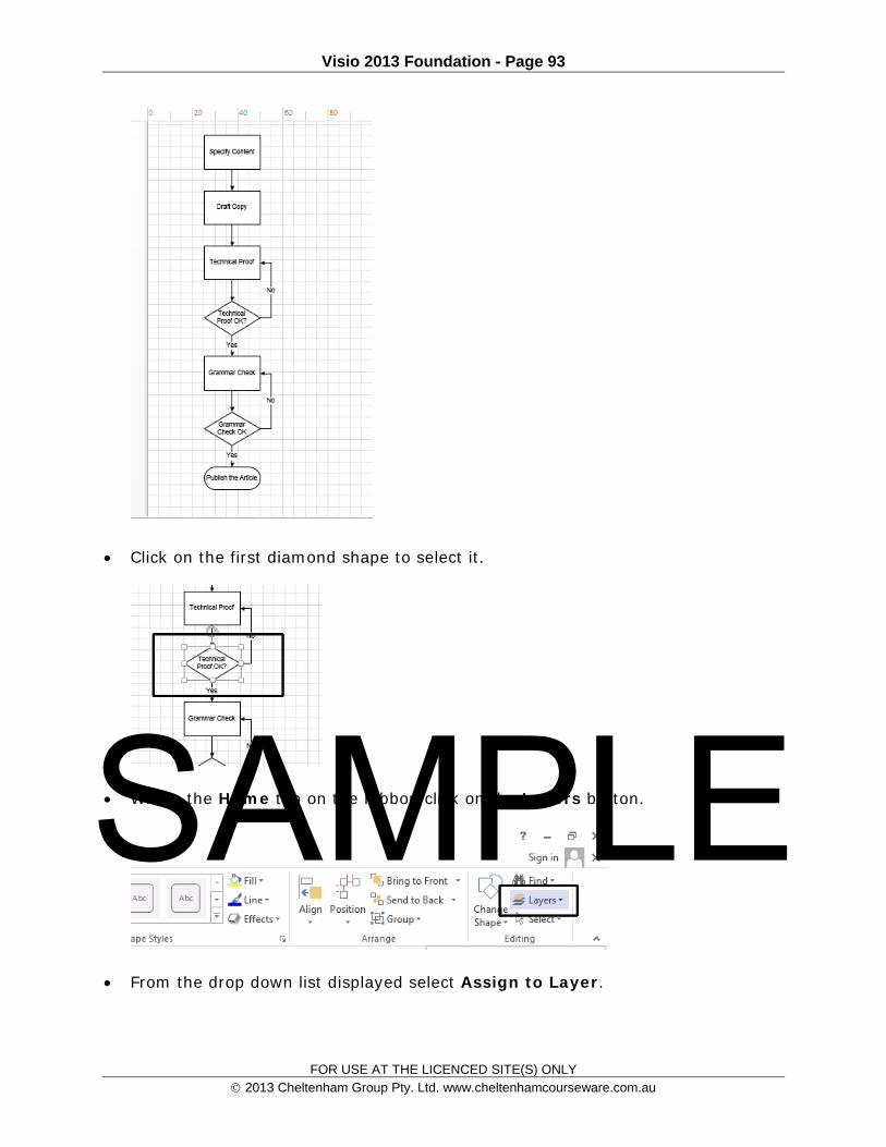
Click on the first diamond shape to select it.
Within the Home tab on the Ribbon click on the Layers button.
From the drop down list displayed select Assign to Layer.
SAMPLE

Visio 2013 Foundation - Page 94
FOR USE AT THE LICENCED SITE(S) ONLY 2013 Cheltenham Group Pty. Ltd. www.cheltenhamcourseware.com.au
This will open the Layer dialog box.
To create a new layer that will be used by the diamond shape, click on the New button within the dialog box. This will display the New dialog box. Type in the name Diamond, and click on the OK button.
The dialog box will now look like this.
SAMPLE
Visio 2013 Foundation - Page 95
FOR USE AT THE LICENCED SITE(S) ONLY 2013 Cheltenham Group Pty. Ltd. www.cheltenhamcourseware.com.au
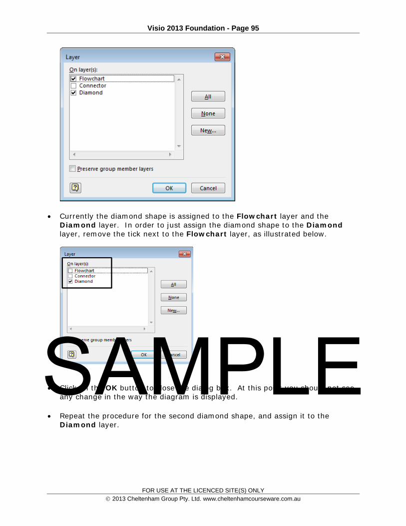
Currently the diamond shape is assigned to the Flowchart layer and the Diamond layer. In order to just assign the diamond shape to the Diamond layer, remove the tick next to the Flowchart layer, as illustrated below.
Click on the OK button to close the dialog box. At this point you should not see any change in the way the diagram is displayed.
Repeat the procedure for the second diamond shape, and assign it to the Diamond layer.
SAMPLE

Visio 2013 Foundation - Page 96
FOR USE AT THE LICENCED SITE(S) ONLY 2013 Cheltenham Group Pty. Ltd. www.cheltenhamcourseware.com.au
Showing and hiding layers Click on the Home tab and then click on the Layers button. From the drop
down displayed, click on the Layer Properties command.
This will display the Layer Properties dialog box.
Within the Diamond row, remove the tick under the Visible column. Within the Connector row, remove the tick under the Visible column.
SAMPLE

Visio 2013 Foundation - Page 97
FOR USE AT THE LICENCED SITE(S) ONLY 2013 Cheltenham Group Pty. Ltd. www.cheltenhamcourseware.com.au
Click on the OK button and you will now see your diagram displayed, without the Connector layer, and also without the Diamond layer.
Save your changes and close the Visio program.
SAMPLE

Visio 2013 Foundation - Page 98
FOR USE AT THE LICENCED SITE(S) ONLY 2013 Cheltenham Group Pty. Ltd. www.cheltenhamcourseware.com.au
Managing Pages
Moving between pages Open the Visio program and open a file called Managing Pages. If you look at the bottom-left of the diagram you will see the Page tabs,
indicating that this file contains 5 pages.
Click on each of the tabs in turn, to display the page contents.
Inserting a new page Click on the Page-1 tab. Right click over the Page-1 tab, and from the pop-up menu displayed, select
the Insert Page command.
This will display the Page Setup dialog box, with the Page Properties tab selected. SAMPLE

Visio 2013 Foundation - Page 99
FOR USE AT THE LICENCED SITE(S) ONLY 2013 Cheltenham Group Pty. Ltd. www.cheltenhamcourseware.com.au
Enter a name for the new page, in the name section of the dialog box. Call it My New Page. Click on the OK button. Your screen will now look like the illustration below.
Renaming a page Right click on the page tab of the new page that you have just created. From
the pop-up menu displayed click on the Rename Page command.
The Page tab will be selected as illustrated.
SAMPLE

Visio 2013 Foundation - Page 100
FOR USE AT THE LICENCED SITE(S) ONLY 2013 Cheltenham Group Pty. Ltd. www.cheltenhamcourseware.com.au
Type in a new name. In this case type the word Introduction and press Enter.
Reordering pages Right click on the Introduction page tab and from the pop-up menu displayed,
select the Reorder Pages command.
This will display the Reorder Page dialog box, as illustrated below.
SAMPLE

Visio 2013 Foundation - Page 101
FOR USE AT THE LICENCED SITE(S) ONLY 2013 Cheltenham Group Pty. Ltd. www.cheltenhamcourseware.com.au
Select the Introduction page within the dialog box.
Click on the Move Down button, until the Introduction page is displayed at the bottom of the list.
SAMPLE

Visio 2013 Foundation - Page 102
FOR USE AT THE LICENCED SITE(S) ONLY 2013 Cheltenham Group Pty. Ltd. www.cheltenhamcourseware.com.au
Click on the OK button and you will see your new page displayed.
Deleting a page Right click over the Page-6 tab and from the pop-up menu displayed, select the
Delete Page command.
Your screen will now look like this.
Save your changes and close the Visio program.
Creating a Background Page A background page is similar to a master page. A background page appears in
the background of your Drawing page. Open the Visio program and open a file called Background. If necessary change the zoom level so that you can see all the shapes making
up the diagram. To create a background page, click on the Insert tab and select the New Page
command. From the drop down menu displayed click on Background Page.
SAMPLE

Visio 2013 Foundation - Page 103
FOR USE AT THE LICENCED SITE(S) ONLY 2013 Cheltenham Group Pty. Ltd. www.cheltenhamcourseware.com.au
This will open the Page Setup dialog box. Within the Type section of the dialog box, make sure that the Background option is selected.
Enter a name for this background page in the Name box. In this case, enter the name My Background and then click on the OK button. Your screen will now look like this. SAMPLE
Visio 2013 Foundation - Page 104
FOR USE AT THE LICENCED SITE(S) ONLY 2013 Cheltenham Group Pty. Ltd. www.cheltenhamcourseware.com.au
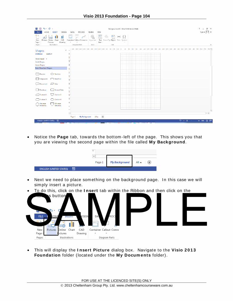
Notice the Page tab, towards the bottom-left of the page. This shows you that you are viewing the second page within the file called My Background.
Next we need to place something on the background page. In this case we will simply insert a picture.
To do this, click on the Insert tab within the Ribbon and then click on the Pictures button.
This will display the Insert Picture dialog box. Navigate to the Visio 2013 Foundation folder (located under the My Documents folder).
SAMPLE

Visio 2013 Foundation - Page 105
FOR USE AT THE LICENCED SITE(S) ONLY 2013 Cheltenham Group Pty. Ltd. www.cheltenhamcourseware.com.au
Double click on a picture file called Clouds. The picture is far too large for what you need, so you will have to use the usual
drag and drop picture re-sizing techniques to make the picture small, as illustrated below.
SAMPLE

Visio 2013 Foundation - Page 106
FOR USE AT THE LICENCED SITE(S) ONLY 2013 Cheltenham Group Pty. Ltd. www.cheltenhamcourseware.com.au
Now that we have created a background page we need to assign it to other pages
Assigning a background page Click on the Page-1 tab so that the contents of the first page are displayed.
SAMPLE

Visio 2013 Foundation - Page 107
FOR USE AT THE LICENCED SITE(S) ONLY 2013 Cheltenham Group Pty. Ltd. www.cheltenhamcourseware.com.au
Click on the Design tab and then click on the More control in the Page Setup section, as illustrated below.
This will display the Page Setup dialog box. Click the Page Properties tab. In the Type section make sure that Background is selected.
Click on the down arrow within the Background section and select the name of the background that you want to assign to the selected page. In this case select My Background.
SAMPLE

Visio 2013 Foundation - Page 108
FOR USE AT THE LICENCED SITE(S) ONLY 2013 Cheltenham Group Pty. Ltd. www.cheltenhamcourseware.com.au
Click on the OK button and the background will be assigned to the page. An example is illustrated below. The background is displayed beneath the diagram.
NOTE: You could use this technique to display text, such as DRAFT, or CONFIDENTIAL, behind diagrams that are still in a draft stage, or that are confidential.
Save your changes and close the Visio program. SAMPLE
Visio 2013 Foundation - Page 109
FOR USE AT THE LICENCED SITE(S) ONLY 2013 Cheltenham Group Pty. Ltd. www.cheltenhamcourseware.com.au
Printing and Sharing Drawings
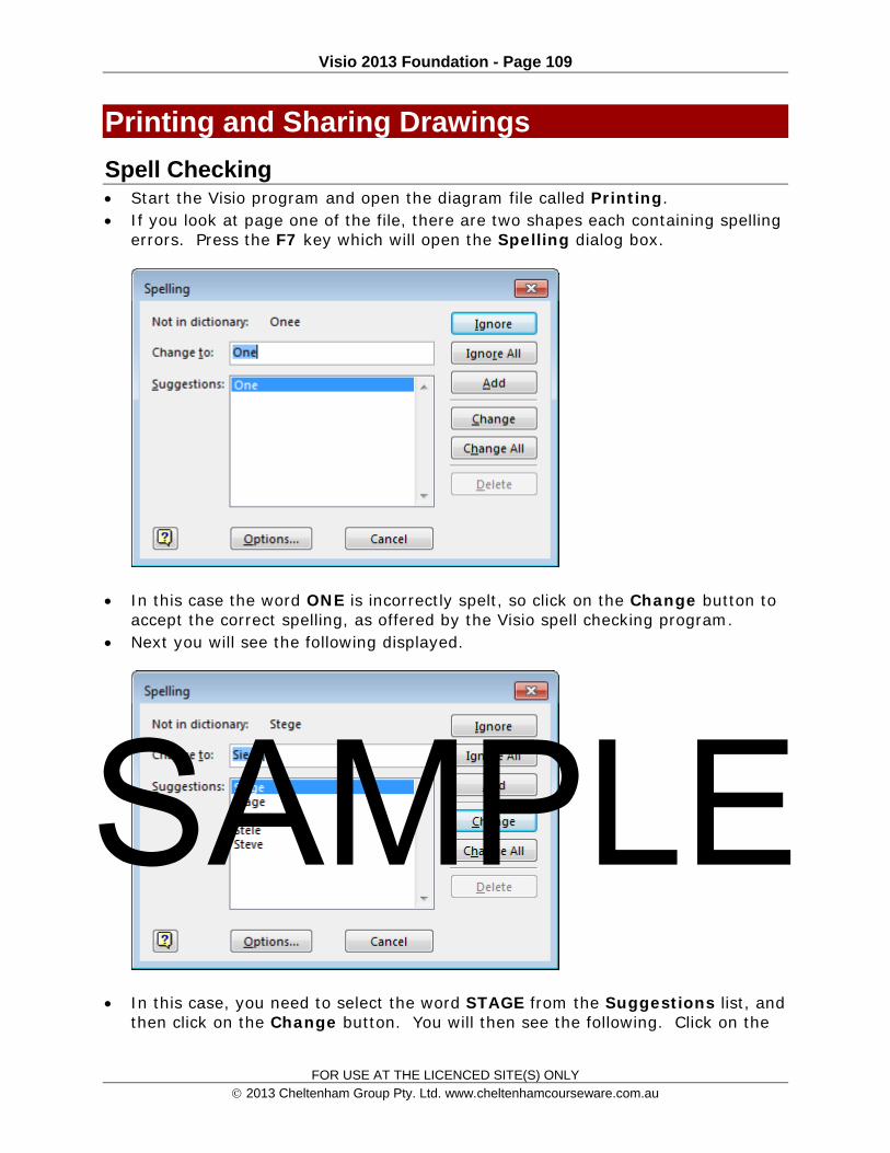
Spell Checking Start the Visio program and open the diagram file called Printing. If you look at page one of the file, there are two shapes each containing spelling
errors. Press the F7 key which will open the Spelling dialog box.
In this case the word ONE is incorrectly spelt, so click on the Change button to accept the correct spelling, as offered by the Visio spell checking program.
Next you will see the following displayed.
In this case, you need to select the word STAGE from the Suggestions list, and then click on the Change button. You will then see the following. Click on the
SAMPLE

Visio 2013 Foundation - Page 110
FOR USE AT THE LICENCED SITE(S) ONLY 2013 Cheltenham Group Pty. Ltd. www.cheltenhamcourseware.com.au
OK button.
The words are now all spelt correctly.
Paper size and orientation Click on the Design tab and within the Page Setup section click on the Size
button.
From the drop down list displayed select the required paper size, normally Letter within North America and A4 elsewhere.
SAMPLE

Visio 2013 Foundation - Page 111
FOR USE AT THE LICENCED SITE(S) ONLY 2013 Cheltenham Group Pty. Ltd. www.cheltenhamcourseware.com.au
You can also click on the Orientation button to change the page orientation.
Print Preview Before printing a drawing you can preview the drawing to see how it will print. Click on the File tab.
Click on the Print tab and your screen will look like this.
SAMPLE

Visio 2013 Foundation - Page 112
FOR USE AT THE LICENCED SITE(S) ONLY 2013 Cheltenham Group Pty. Ltd. www.cheltenhamcourseware.com.au
The page is displayed within the right side of the screen and you can use the navigation controls in zoom in or out and to move between pages.
Setting additional printer options Click on the Design tab and then click on the More button within the Page
Setup section of the Ribbon.
This will display the Page Setup dialog box.
Checkout the tabs within this dialog box to see what other options are available. The Page Size tab is shown below. SAMPLE

Visio 2013 Foundation - Page 113
FOR USE AT THE LICENCED SITE(S) ONLY 2013 Cheltenham Group Pty. Ltd. www.cheltenhamcourseware.com.au
Save any changes that you may have made and close the Visio program.
SAMPLE


