Vision-based adaptive assistance and haptic guidance for safe wheelchair corridor following Vishnu K.Narayanan a , Fran¸cois Pasteau b , Maud Marchal c , Alexandre Krupa a , Marie Babel c a Inria Rennes - Bretagne Atlantique and IRISA, France. b Ergovie, France. c Inria Rennes - Bretagne Atlantique, INSA Rennes and IRISA, France. Abstract In case of motor impairments, steering a wheelchair can become a hazardous task. Joystick jerks induced by uncontrolled motions may lead to wall colli- sions when a user steers a wheelchair along a corridor. This work introduces a low-cost assistive and guidance system for indoor corridor navigation in a wheelchair, which uses purely visual information, and which is capable of providing automatic trajectory correction and haptic guidance in order to avoid wall collisions. A visual servoing approach to autonomous corridor fol- lowing serves as the backbone to this system. The algorithm employs natural image features which can be robustly extracted in real time. This algorithm is then fused with manual joystick input from the user so that progressive assistance and trajectory correction can be activated as soon as the user is in danger of collision. A force feedback in conjunction with the assistance is provided on the joystick in order to guide the user out of his dangerous tra- jectory. This ensures intuitive guidance and minimal interference from the trajectory correction system. In addition to being a low-cost approach, it can be seen that the proposed solution does not require an a-priori environment model. Experiments on a robotised wheelchair equipped with a monocular camera prove the capability of the system to adaptively guide and assist a user navigating in a corridor. Keywords: Vision-based robotics, Visual servoing, Assistive robotics, Wheelchair navigation Email address: [email protected](Vishnu K.Narayanan) Preprint submitted to Computer Vision and Image Understanding February 3, 2016
Transcript
Vision-based adaptive assistance and haptic guidance for
safe wheelchair corridor following
Vishnu K.Narayanana, Francois Pasteaub, Maud Marchalc, AlexandreKrupaa, Marie Babelc
aInria Rennes - Bretagne Atlantique and IRISA, France.bErgovie, France.
cInria Rennes - Bretagne Atlantique, INSA Rennes and IRISA, France.
Abstract
In case of motor impairments, steering a wheelchair can become a hazardoustask. Joystick jerks induced by uncontrolled motions may lead to wall colli-sions when a user steers a wheelchair along a corridor. This work introducesa low-cost assistive and guidance system for indoor corridor navigation ina wheelchair, which uses purely visual information, and which is capable ofproviding automatic trajectory correction and haptic guidance in order toavoid wall collisions. A visual servoing approach to autonomous corridor fol-lowing serves as the backbone to this system. The algorithm employs naturalimage features which can be robustly extracted in real time. This algorithmis then fused with manual joystick input from the user so that progressiveassistance and trajectory correction can be activated as soon as the user isin danger of collision. A force feedback in conjunction with the assistance isprovided on the joystick in order to guide the user out of his dangerous tra-jectory. This ensures intuitive guidance and minimal interference from thetrajectory correction system. In addition to being a low-cost approach, it canbe seen that the proposed solution does not require an a-priori environmentmodel. Experiments on a robotised wheelchair equipped with a monocularcamera prove the capability of the system to adaptively guide and assist auser navigating in a corridor.
Preprint submitted to Computer Vision and Image Understanding February 3, 2016
1. Introduction
Wheelchairs are versatile assistive devices that are able to address virtu-ally all physically disabling pathologies, and they help millions of people inachieving mobility. But severe motor disabilities like Parkinson’s disease aswell as visual impairments prevent people from steering a wheelchair effec-tively, particularly in constrained environments [1]. In addition, difficultiesappear during long-term driving. Depending on the handicap, steering awheelchair along a corridor can then become a difficult task especially whencorridors are narrow enough to induce an uncomfortable sensation in navi-gation [2].
It is well known that individual mobility is an integral part of the mentaland social well-being of a disabled person [3]. Therefore smart devices haveto be designed in order to help a wheelchair user navigate efficiently withoutthe help of another person. One can say that recent advances in roboticshave facilitated the enhancement of a simple electric wheelchair into a smartwheelchair. Here the idea is to assist a user in fundamental navigation taskslike corridor following, doorway passing and to perform local obstacle avoid-ance. Different projects like the TAO Project [4], the NavChair [5], EuropeanFP7 Radhar project [6] and the recent SYSIASS project [2] were indeed ableto design systems that take partial/full control from the user for safe andeffective navigation assistance.
The aim of this paper is to then introduce an adaptive assistive andguidance system in order to prevent wall collisions when a user manuallysteers a wheelchair in a corridor. While the systems mentioned above considera multi-sensor architecture and known maps of the operating environment,the proposed solution relies on low-cost architecture which includes a singlemonocular camera and a haptic joystick. Moreover, the general directiontaken in Smart Wheelchair design is to propose a complete system built fromthe ground up. While some recent works introduce adaptable designs forincreasing the assistive capabilities in an off-the-shelf electric wheelchair [4,5, 6, 7, 8], the systems are tested and validated on specially built wheelchairsor mobile robots with the exception of a few projects which adapt existingpowered wheelchairs with the requisite software or hardware [2, 9, 10].
Therefore the aim here is to design a modular system tested on an off-the-shelf electric wheelchair. In addition, a fully vision-based setup along with
2
a map-less design facilitates easier commercialization and widespread usage.Thus the goal is to design a robust vision-based control system that could beused in order to augment user teleoperation to derive a semi-autonomoussolution for corridor following. Such semi-autonomous or shared controlwheelchair systems would be helpful in conditions where motor impairmentsmay hinder secure and effective navigation, by providing safe assistance inperforming fundamental tasks like corridor following while maintaining highlevel control with the user.
A variety of solutions have been proposed in the area of corridor followingwith mobile/wheeled robots [11]. While specifically considering vision-basedcorridor following using a mobile robot, in [12] a visual approach was de-signed using an omni-directional camera with the system utilizing a visualmemory framework. Furthermore, in [13] two vision-based control algorithmsfor corridor navigation were presented that exploited the geometry of a typ-ical corridor. The first one used the optical flow measured from the corri-dor’s lateral walls to generate an angular velocity command for the mobilerobot. The second scheme found the perspective lines of the walls meetingthe floor to generate the angular velocity command for the robot. More-over [14] demonstrates a stable image-based and position-based controllerfor autonomous mobile robot navigation in corridors that considers parallelperspective lines on the floor. Whereas in [15], visual servoing based on avanishing point detection is fused with appearance-based process to monitorand control the position of a mobile robot in a corridor. Therefore, the geom-etry of a corridor in an image is a viable solution to employ while designingvision-based algorithms (or visual tasks) around it for realising the task ofcorridor following.
But this visual task has to be blended with manual control/user intentionso that the user maintains a higher level control over the wheelchair motion.Most smart wheelchair designs give the high-level control (e.g. goal selection,path planning) to the user, and the low-level control (e.g. motion controlcommands, obstacle avoidance) to the robot [2, 4, 5, 6, 16]. Recently, a va-riety of solutions have been proposed that use non-invasive Brain-ComputerInterfaces (BCI) for assessing the user intent and then augment the user in-tent using external sensors for safe navigation [9, 10, 17]. Using BCIs mayprovide an accurate estimate of user intention, but the major drawback liesin the fact that the user must concentrate very hard to convey his intent.This may be a difficult task, especially for people with motor disabilities. Onthe other hand, using voice [18] and/or gaze [19] as user tele-operation have
3
limited scope in terms of modularity as well. Therefore straightforward andmodular solution would be to blend manual control from a joystick with robotcontrol in order to create a co-operative/collaborative system with the useras the high level controller. This concept was demonstrated in [16] wherethe manual control from the joystick was augmented with an autonomouscontroller capable of obstacle avoidance. Moreover in [7], a linear controlblending formalism was introduced in order to fuse user and robot controlfor assisted doorway traversal in a wheelchair.
Also, to maximize the acceptability of the assistance solution, this as-sistance has to be progressively activated only when necessary and to bedeactivated as soon as the user wants to act by himself [1]. As a conse-quence, the control process has to be designed as a man-in-the-loop schemewhere the user remains the leader of the navigation process and automatictrajectory correction is adaptively activated when in danger.
In conjunction with automatic trajectory correction, a guiding joystickforce is necessary in the case where users suffer from visual and/or cognitiveimpairments and are not able to clearly observe their unsafe trajectory. It canalso be seen as a communication channel between the user and the wheelchaircontroller for a better user experience where such an active feedback canlead to minimal interference from the automatic trajectory correction system[20]. This concept of haptic feedback for wheelchair navigation assistancehas been previously explored mainly as a mechanism for obstacle avoidancewhere the feedback was calculated from the classical potential field method[21, 22, 23, 24]. Recently in the context of the European FP7 Radhar project,haptic feedback was provided in order to achieve a bilateral guidance channelwhere the haptic controller relays the intention of the system so that the useris able to overrule actions if needed [20]. Therefore it is efficient to provide aforce feedback which is in conjunction or in proportion with the automatictrajectory correction so that there is an intuitive form of communication withthe user.
The proposed work therefore presents an image-based control scheme tointegrate an autonomous visual navigation task with user teleoperation whilea user is manually driving a wheelchair. This provides progressive assistancewhenever the user is in danger of collision. In addition, a guiding force, whichis also explicitly modelled from visual information, is applied on the joystickin order to notify the user of his/her unsafe trajectory. The system is thenanalysed on an off-the-shelf wheelchair equipped with a monocular cameraand a haptic joystick.
4
Consequently, Section 2 details the proposed approach and contributionsof the work. Section 3 presents the geometric modelling of the system, Sec-tion 4 illustrates the image features extraction processes and Section 5 ex-plains the image-based controller along with the design of the haptic guidancescheme. The experimental analysis is presented in Section 6.
2. Proposed System and Contributions
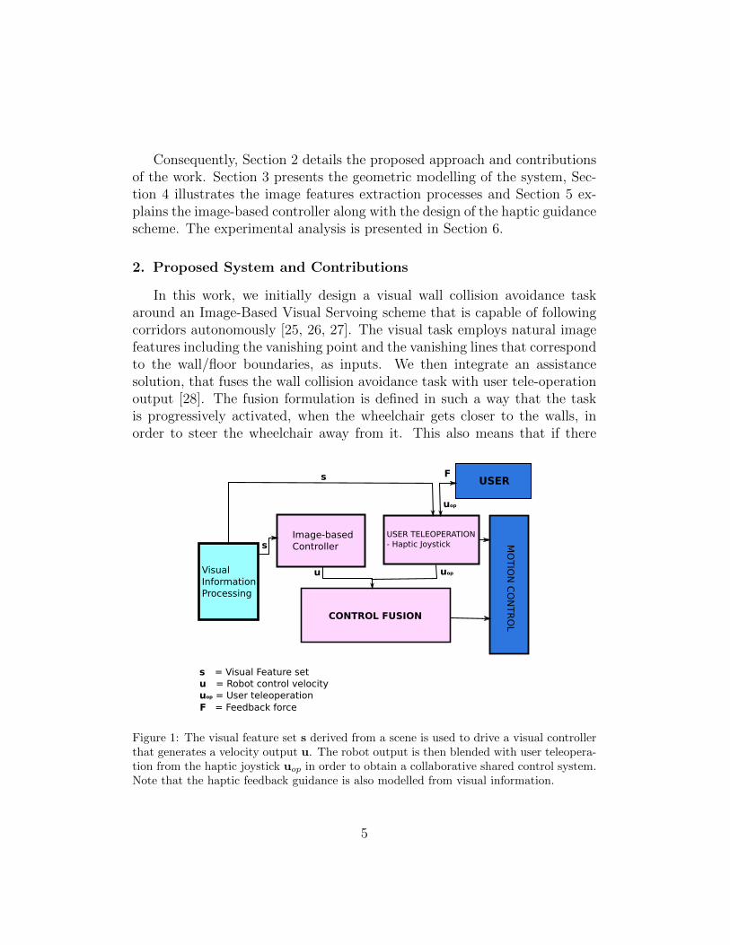
In this work, we initially design a visual wall collision avoidance taskaround an Image-Based Visual Servoing scheme that is capable of followingcorridors autonomously [25, 26, 27]. The visual task employs natural imagefeatures including the vanishing point and the vanishing lines that correspondto the wall/floor boundaries, as inputs. We then integrate an assistancesolution, that fuses the wall collision avoidance task with user tele-operationoutput [28]. The fusion formulation is defined in such a way that the taskis progressively activated, when the wheelchair gets closer to the walls, inorder to steer the wheelchair away from it. This also means that if there
USER TELEOPERATION- Haptic Joystick
CONTROL FUSION
MO
TIO
NC
ON
TR
OL
s = Visual Feature setu = Robot control velocityuop = User teleoperation
s
s
u uop
USER
uop
F
F = Feedback force
Image-based Controller
VisualInformationProcessing
Figure 1: The visual feature set s derived from a scene is used to drive a visual controllerthat generates a velocity output u. The robot output is then blended with user teleopera-tion from the haptic joystick uop in order to obtain a collaborative shared control system.Note that the haptic feedback guidance is also modelled from visual information.
5
is no threat of collision, the user will have full control over the wheelchairmotion. Finally, we design an optimal joystick force feedback in conjunctionwith the trajectory correction process that helps the user to understand thedangerousness of the situation and which intuitively guides him over to a safetrajectory. The progressive assistance and the force fed back in order to guidethe user, are both explicitly modelled from visual information. Therefore theguiding force applied on the joystick will be in conjunction with the automaticcorrection. This will lead to a more intuitive experience since the feedbackforce will concurrently help in trajectory correction (thereby decreasing thesystem effort). An overview of the approach is presented in Figure 1.
As a result, information from an on-board monocular camera is used toexplicitly design an assistive semi-autonomous solution for corridor naviga-tion in a wheelchair that also communicates the intention of the providedassistance to the user.
3. Modelling
We model the wheelchair as a non-holonomic unicycle type robot that isable to move on a horizontal/inclined plane. Two differential wheels locatedin the middle of the robot body provide motion while two passive casterwheels each at the front and rear are required for balance. Therefore the twocomponents of the control velocity (u) are the translational component ualong its forward/backward direction and the angular (steering) componentω.
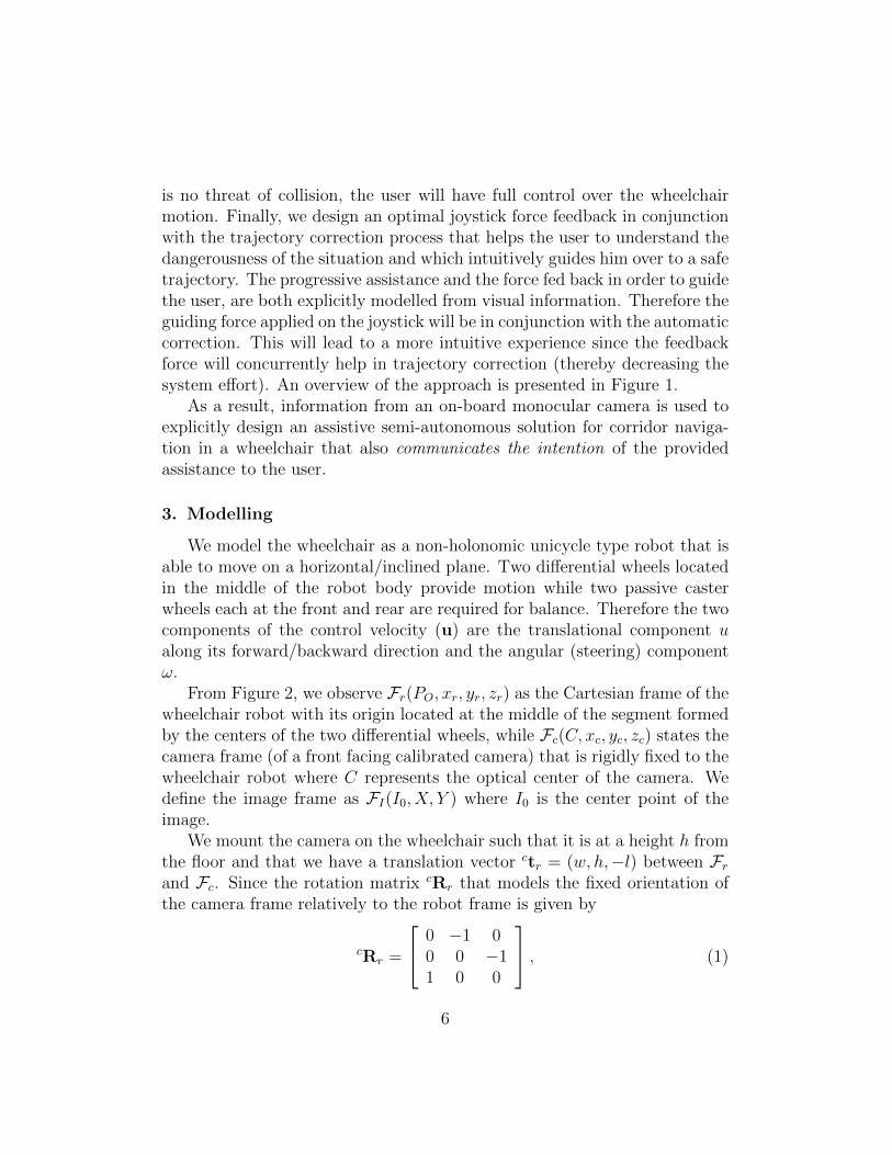
From Figure 2, we observe Fr(PO, xr, yr, zr) as the Cartesian frame of thewheelchair robot with its origin located at the middle of the segment formedby the centers of the two differential wheels, while Fc(C, xc, yc, zc) states thecamera frame (of a front facing calibrated camera) that is rigidly fixed to thewheelchair robot where C represents the optical center of the camera. Wedefine the image frame as FI(I0, X, Y ) where I0 is the center point of theimage.
We mount the camera on the wheelchair such that it is at a height h fromthe floor and that we have a translation vector ctr = (w, h,−l) between Frand Fc. Since the rotation matrix cRr that models the fixed orientation ofthe camera frame relatively to the robot frame is given by
cRr =
0 −1 00 0 −11 0 0
, (1)
6
zc
yc
xc
zc
xcyc
zryr
xr uω
zr
yr
xr
(a)
(b) (c)
P0
C
w
h
lzc
xcyc
zryr
xr uω
Cf
xf
y
Corridor
Wall
(d)
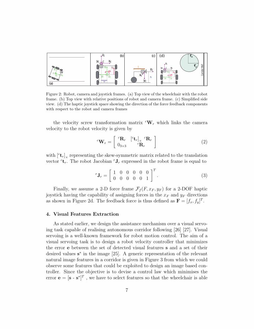
Figure 2: Robot, camera and joystick frames. (a) Top view of the wheelchair with the robotframe. (b) Top view with relative positions of robot and camera frame. (c) Simplified sideview. (d) The haptic joystick space showing the direction of the force feedback componentswith respect to the robot and camera frames
the velocity screw transformation matrix cWr which links the cameravelocity to the robot velocity is given by
cWr =
[cRr [ctr]×
cRr
03×3cRr
](2)
with [ctr]× representing the skew-symmetric matrix related to the translationvector ctr. The robot Jacobian rJr expressed in the robot frame is equal to
rJr =
[1 0 0 0 0 00 0 0 0 0 1
]T. (3)
Finally, we assume a 2-D force frame Ff (F, xF , yF ) for a 2-DOF hapticjoystick having the capability of assigning forces in the xF and yF directionsas shown in Figure 2d. The feedback force is thus defined as F = [fx, fy]
T .
4. Visual Features Extraction
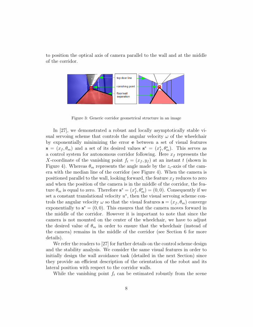
As stated earlier, we design the assistance mechanism over a visual servo-ing task capable of realising autonomous corridor following [26] [27]. Visualservoing is a well-known framework for robot motion control. The aim of avisual servoing task is to design a robot velocity controller that minimizesthe error e between the set of detected visual features s and a set of theirdesired values s∗ in the image [25]. A generic representation of the relevantnatural image features in a corridor is given in Figure 3 from which we couldobserve some features that could be exploited to design an image based con-troller. Since the objective is to devise a control law which minimises theerror e = [s - s∗]T , we have to select features so that the wheelchair is able
7
to position the optical axis of camera parallel to the wall and at the middleof the corridor.
Figure 3: Generic corridor geometrical structure in an image
In [27], we demonstrated a robust and locally asymptotically stable vi-sual servoing scheme that controls the angular velocity ω of the wheelchairby exponentially minimizing the error e between a set of visual featuress = (xf , θm) and a set of its desired values s∗ = (x∗f , θ
∗m). This serves as
a control system for autonomous corridor following. Here xf represents theX-coordinate of the vanishing point ft = (xf , yf ) at an instant t (shown inFigure 4). Whereas θm represents the angle made by the zc-axis of the cam-era with the median line of the corridor (see Figure 4). When the camera ispositioned parallel to the wall, looking forward, the feature xf reduces to zeroand when the position of the camera is in the middle of the corridor, the fea-ture θm is equal to zero. Therefore s∗ = (x∗f , θ
∗m) = (0, 0). Consequently if we
set a constant translational velocity u∗, then the visual servoing scheme con-trols the angular velocity ω so that the visual features s = (xf , θm) convergeexponentially to s∗ = (0, 0). This ensures that the camera moves forward inthe middle of the corridor. However it is important to note that since thecamera is not mounted on the center of the wheelchair, we have to adjustthe desired value of θm in order to ensure that the wheelchair (instead ofthe camera) remains in the middle of the corridor (see Section 6 for moredetails).
We refer the readers to [27] for further details on the control scheme designand the stability analysis. We consider the same visual features in order toinitially design the wall avoidance task (detailed in the next Section) sincethey provide an efficient description of the orientation of the robot and itslateral position with respect to the corridor walls.
While the vanishing point ft can be estimated robustly from the scene
8
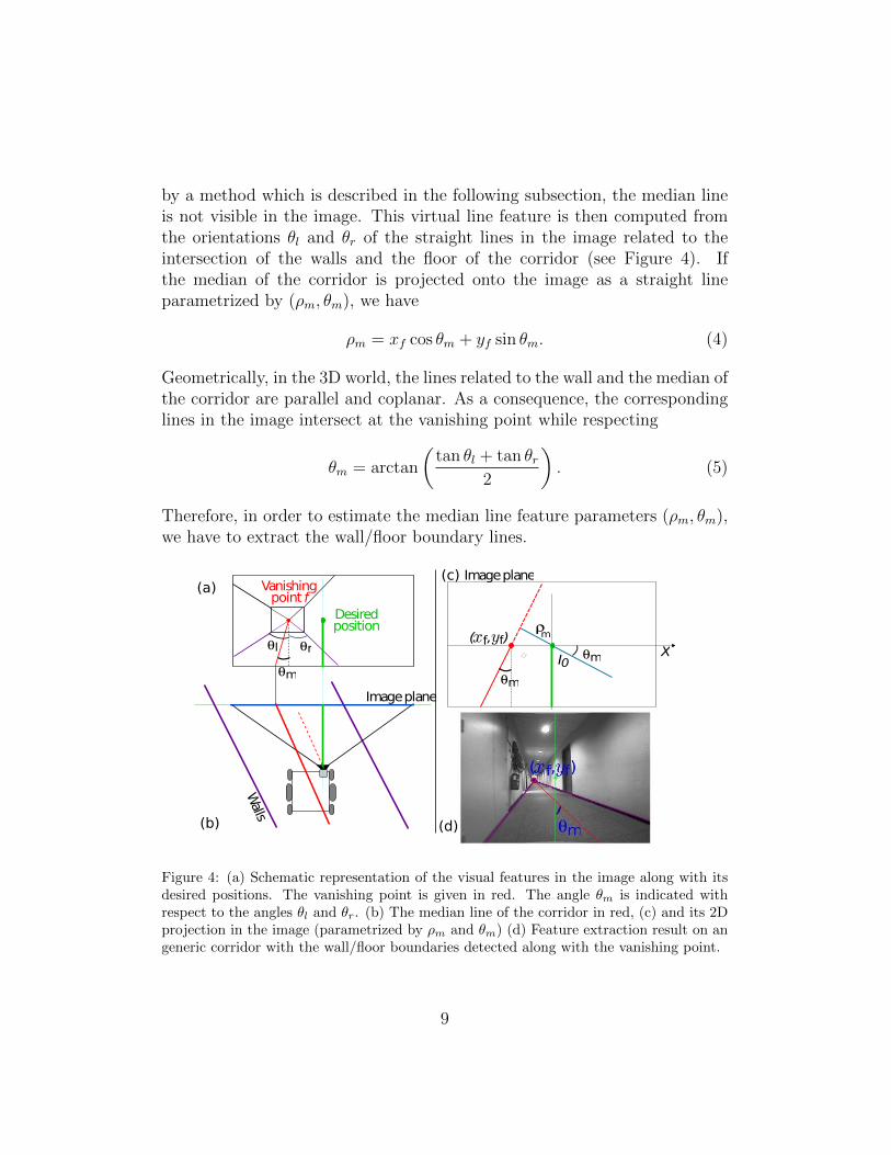
by a method which is described in the following subsection, the median lineis not visible in the image. This virtual line feature is then computed fromthe orientations θl and θr of the straight lines in the image related to theintersection of the walls and the floor of the corridor (see Figure 4). Ifthe median of the corridor is projected onto the image as a straight lineparametrized by (ρm, θm), we have
ρm = xf cos θm + yf sin θm. (4)
Geometrically, in the 3D world, the lines related to the wall and the median ofthe corridor are parallel and coplanar. As a consequence, the correspondinglines in the image intersect at the vanishing point while respecting
θm = arctan
(tan θl + tan θr
2
). (5)
Therefore, in order to estimate the median line feature parameters (ρm, θm),we have to extract the wall/floor boundary lines.
Imageplane
Walls
( , )
Y
θm
ρ
ImageplaneVanishingpoint f
θl
Desiredposition
θr XθmI0
xf yf
(a)
(b)
(c)
(d)
θm
m
Figure 4: (a) Schematic representation of the visual features in the image along with itsdesired positions. The vanishing point is given in red. The angle θm is indicated withrespect to the angles θl and θr. (b) The median line of the corridor in red, (c) and its 2Dprojection in the image (parametrized by ρm and θm) (d) Feature extraction result on angeneric corridor with the wall/floor boundaries detected along with the vanishing point.
9
4.1. Estimation of xf
For indoor scenes, estimating the vanishing point robustly and in realtime is still an open area of research in computer vision. The vanishing pointcorresponds to the point where a significant number of straight lines mayintersect. Therefore in the case of navigating through a corridor the problemis much easier to tackle.
We use the classical Gaussian sphere projection framework [29] [30], wherethe idea is to project onto this sphere, the set of detected non-vertical straightlines in the image. The point where a maximum number of these non-verticallines intersect is chosen as the vanishing point. For extracting these non-vertical straight lines in the image, the Line Segment Detection (LSD) algo-rithm is used [31]. The algorithm is based on local gradient orientations inthe image, from which major segments are detected. The detected segmentsare then classified into vertical lines and non-vertical lines and latter is usedfor estimating the vanishing point.
However, the main issue of the LSD algorithm is the removal of one linewhen the direction of the observed gradient changes. Thus, to increase therobustness, a dedicated merging process is applied to a group of segmentsthat can be considered as a single straight line. For two segments, this processis done by taking into account the slope and extremities, and if they are closeenough, they are merged to form a unique line. More details are given in[32].
Since the vanishing point ft is estimated at each frame during a sequence,a factor αf ∈ ]0, 1[ is introduced for temporal filtering as
ft = αfft−1 + (1− αf )ft
in order to ensure a smooth variation of the resulting estimated vanishingpoint in the current frame. The value of αf is empirically tuned and hasbeen chosen for the experiments at αf = 0.1. It can be postulated that sincethe temporal variation of the vanishing point is not very high as a wheelchairwith a front facing camera moves forward in a corridor, the filtering processwill be robust to variations in the factor αf .
4.2. Estimation of θm
As we can see from Eqn. 5, θm is a function of θl and θr and thereforethey have to be determined in order to estimate θm. We can say that theangles θl and θr can be easily calculated if we have an accurate estimate
10
of the wall/floor boundaries. Among the variety of techniques that havebeen proposed in the area of wall/floor boundary detection, in [33] wall/floorfeatures are defined by the corners corresponding to the intersection of avertical line and the floor plane. Whereas in [34], floor boundary is estimatedby a dynamical Bayesian network model which is applied on each column ofthe image.
But we know that in an indoor corridor scene (see Figure 3) wall/floorboundary lines correspond to non-vertical lines that intersect the vanishingpoint. Therefore in our proposed scheme, a set of non-vertical lines aresearched for along the image that correspond to the wall/floor boundarybased on two criteria: the first one being that they contribute to the vanishingpoint and, the second one being that they cross the bottom extremities ofmost number of vertical lines. Again the non-vertical lines are detected andclassified using the LSD algorithm. In order to minimize false positives andimprove robustness, a maximal distance between the vertical line extremityand the vanishing line is defined. The result of the feature extraction processon a generic image can be seen in Figure 4d.
Then, from the angles θl and θr, the value of θm is directly obtained usingEqn (5).
4.3. Robustness of Feature Extraction
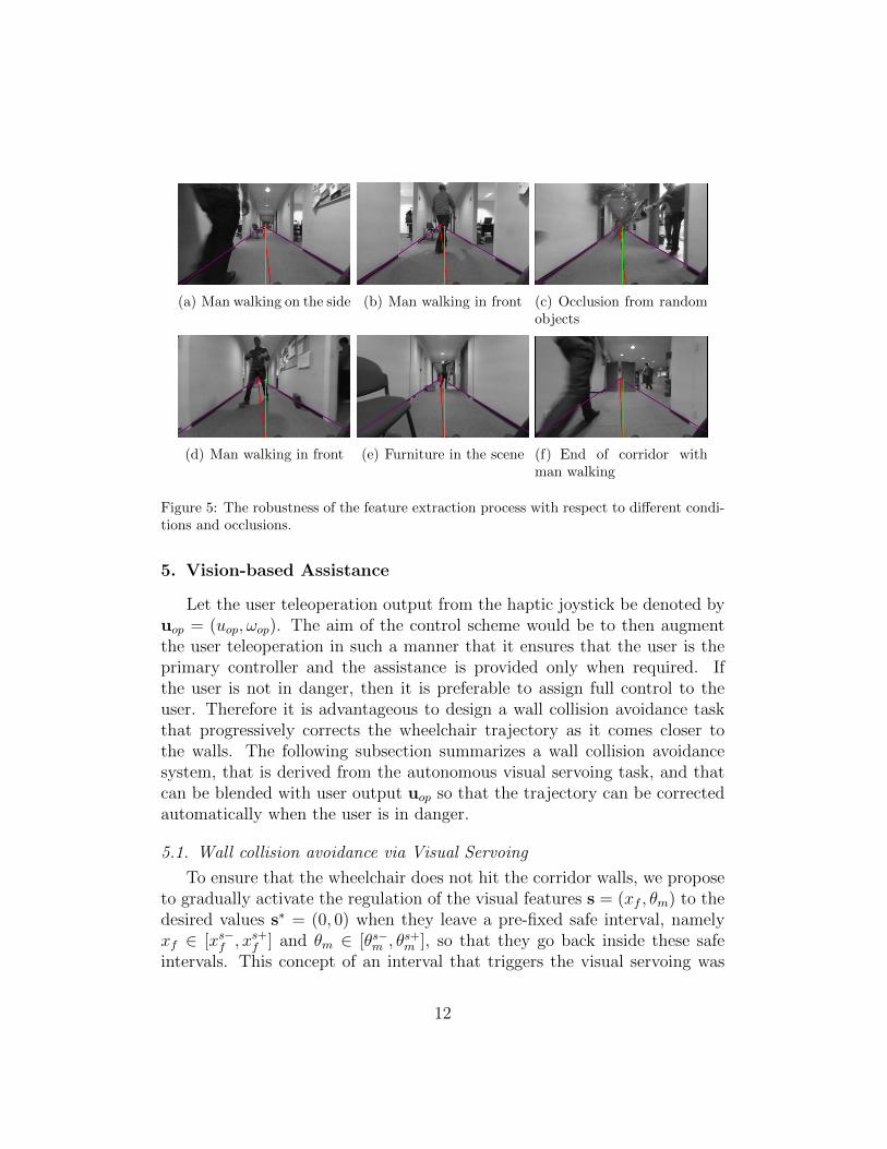
Since the control scheme detailed in the following Section is driven bythe visual features xf and θm, the estimation of the features should be fairlyrobust with respect to different conditions occurring in a indoor corridordriving scene. We present a small driving sequence in Figure 5 with a varietyof disturbances occurring in the scene. On each camera frame output thevanishing point is represented by the red cross (the intersection of all thelines in the image) and the median line of the corridor is represented by thered line. The wall/floor boundaries are shown in purple. It can be observedin all the examples that the estimation of the features is quite accurate.Even when there is a direct occlusion with persons moving in front of thecamera, the vanishing point position and the median line is correct. At theend of the corridor when there is very little composite wall/floor boundarythe estimation is consistent, owing partly to the temporal filter used in theestimation of xf .
11
(a) Man walking on the side (b) Man walking in front (c) Occlusion from randomobjects
(d) Man walking in front (e) Furniture in the scene (f) End of corridor withman walking
Figure 5: The robustness of the feature extraction process with respect to different condi-tions and occlusions.
5. Vision-based Assistance
Let the user teleoperation output from the haptic joystick be denoted byuop = (uop, ωop). The aim of the control scheme would be to then augmentthe user teleoperation in such a manner that it ensures that the user is theprimary controller and the assistance is provided only when required. Ifthe user is not in danger, then it is preferable to assign full control to theuser. Therefore it is advantageous to design a wall collision avoidance taskthat progressively corrects the wheelchair trajectory as it comes closer tothe walls. The following subsection summarizes a wall collision avoidancesystem, that is derived from the autonomous visual servoing task, and thatcan be blended with user output uop so that the trajectory can be correctedautomatically when the user is in danger.
5.1. Wall collision avoidance via Visual Servoing
To ensure that the wheelchair does not hit the corridor walls, we proposeto gradually activate the regulation of the visual features s = (xf , θm) to thedesired values s∗ = (0, 0) when they leave a pre-fixed safe interval, namelyxf ∈ [xs−f , xs+f ] and θm ∈ [θs−m , θs+m ], so that they go back inside these safeintervals. This concept of an interval that triggers the visual servoing was
12
introduced in [35] and used in [36] to ensure the visibility of an organ sectionduring remote ultrasound tele-echography.
Let H = Diag(hxf , hθm) be a diagonal matrix that weights the visual errorwhere hxf ∈ [0; 1] and hθm ∈ [0; 1] are varying weights respectively associatedto the visual features xf and θm. Owing to this definition we can proposethe following control law that sets the system velocity u = (u, ω) aimed atkeeping the visual features inside their interval:
u = −λ(HJs)+He, (6)
where λ > 0 is the control gain, e = s − s∗ is the visual error and Js is theimage Jacobian that links the variation of the visual features to the robotcontrol input such that s = Jsu. Whereas (HJs)
+ is the Moore-Penrosepseudo-inverse of (HJs).
The image Jacobian Js was determined in [26] and was formulated asfollows:
Js = LscWr
rJr (7)
with Ls being the interaction matrix that relates the variation of the visualfeatures to the camera velocity screw. It is defined as
]with λθm = cos(θm)/h where h is the distance of the camera from the floor(see the definition of ctr in Section 3). By combining the expression for therobot Jacobian rJr in Eqn. (3) and the expression for the velocity transfor-mation matrix cWr in Eqn. (2), we reformulate Eqn. (7) as
Js=
[0 1 + x2f
−λθmρm −λθml cos(θm) + λθmwρm + ρm sin(θm)
]=
[JxfJθm
]. (8)
In the definition of the weight matrix H = Diag(hxf , hθm), a zero weightmeans that the related visual feature is not regulated by the visual servoing.The matrix H allows then to add or remove any visual feature in the controllaw when desired and can totally deactivate the visual servoing when H iszero. In order to gradually activate the wall avoidance task when a visualfeature leaves its safe interval, we propose to define the weight related to xf
13
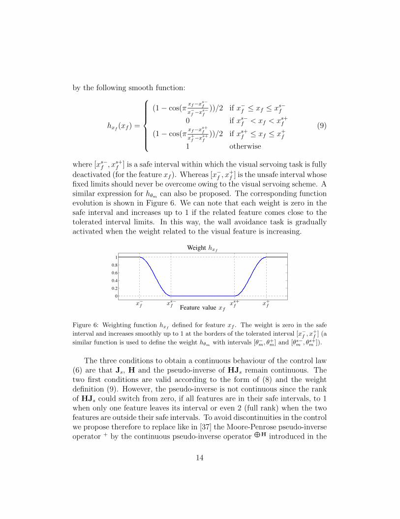
by the following smooth function:
hxf (xf ) =
(1− cos(π
xf−xs−fx−f −x
s−f
))/2 if x−f ≤ xf ≤ xs−f
0 if xs−f < xf < xs+f
(1− cos(πxf−xs+fx+f −x
s+f
))/2 if xs+f ≤ xf ≤ x+f
1 otherwise
(9)
where [xs−f , xs+f ] is a safe interval within which the visual servoing task is fully
deactivated (for the feature xf ). Whereas [x−f , x+f ] is the unsafe interval whose
fixed limits should never be overcome owing to the visual servoing scheme. Asimilar expression for hθm can also be proposed. The corresponding functionevolution is shown in Figure 6. We can note that each weight is zero in thesafe interval and increases up to 1 if the related feature comes close to thetolerated interval limits. In this way, the wall avoidance task is graduallyactivated when the weight related to the visual feature is increasing.
0
0.2
0.4
0.6
0.8
1
x�f x+
fxs+fFeature value xf
Weight hxf
xs�f
Figure 6: Weighting function hxfdefined for feature xf . The weight is zero in the safe
interval and increases smoothly up to 1 at the borders of the tolerated interval [x−f , x+f ] (a
similar function is used to define the weight hθm with intervals [θ−m, θ+m] and [θs−m , θs+m ]).
The three conditions to obtain a continuous behaviour of the control law(6) are that Js, H and the pseudo-inverse of HJs remain continuous. Thetwo first conditions are valid according to the form of (8) and the weightdefinition (9). However, the pseudo-inverse is not continuous since the rankof HJs could switch from zero, if all features are in their safe intervals, to 1when only one feature leaves its interval or even 2 (full rank) when the twofeatures are outside their safe intervals. To avoid discontinuities in the controlwe propose therefore to replace like in [37] the Moore-Penrose pseudo-inverseoperator + by the continuous pseudo-inverse operator
⊕H introduced in the
14
framework of varying-feature-set [38]. This operator allows the inversion of amatrix say J weighted by a diagonal matrix say H by applying the followingdefinition:
J⊕
H =∑P∈B(k)
(∏i∈P
hi
)(∏i/∈P
(1− hi)
)J+P (10)
where J is a matrix of size (k × n), H is a diagonal activation matrix of size(k× k) whose components (hi)i∈[1...k] are included in the interval [0, 1]. B(k)is the set of all the combinations formed by the integers belonging between1 and k (for example B(2) = {∅, {1}, {2}, {1, 2}}). P is any element of thisset and JP = H0J with H0 being a (k × k) diagonal matrix whose diagonalcomponent (i, i) is equal to 1 if i ∈ P and to 0 otherwise. All the theoreticalbases including the proof of continuity of this inversion operator are presentedin [38]. By applying this operator (with k = 2), the continuous inversion ofthe image Jacobian Js activated by the weight matrix H can be obtained as
J⊕
Hs = hxf (1− hθm)
[Jxf01×2
]++ (1− hxf )hθm
[01×2Jθm
]++ hxfhθmJ
+s
(11)We can note that if both the weights of H are equal to 1 (full activation of
the wall avoidance task) then the matrix J⊕
Hs is exactly equal to (HJs)
+Hand we have the same equality if all the weights are zero (deactivation of thewall avoidance task).
Hence the control law (6) can be replaced by the following control lawensuring the wall avoidance task with a continuous behaviour:
u = −λJ⊕
Hs e. (12)
5.2. Fusion of User and Robot Control
In order to create a semi-autonomous system that prevents the user fromhitting the lateral walls while he is manually driving the wheelchair, manualcontrol has to be fused with the wall collision avoidance task. The abovevisual task constraints only the DOFs that regulates the activated featuresinto their safe interval. It is then possible to control the remaining DOFsusing the well established redundancy formalism [39]. Therefore when boththe features have returned to their safe intervals, all the DOFs are fullyavailable for the manual control since the visual task is fully deactivated.
This also means that the desired features s∗ will never be reached (whichis not a problem since the objective of the visual servoing is only to bring
15
them back in their safe intervals). The wall avoidance task can therefore beblended with user teleoperation output uop from the haptic joystick so that
u = −λJ⊕
Hs e + P⊕uop (13)
where P⊕ = I2 − J⊕
Hs Js is the projection operator presented in [37]. The
projection operator P⊕ projects the components of uop (which is the desireduser teleoperation velocity output) onto the null space of the wall collisionavoidance task so that manual control does not disturb the visual task whichhas higher priority when in danger. But when both features are in their safeintervals, the visual task is fully deactivated and the user has full control asP⊕ = I2. We then obtain a smooth and progressive trajectory correctionframework that is only activated in case of danger.
5.3. Design of Haptic Guidance
Such a semi-autonomous assistive system which provides adaptive assis-tance in the form of wall collision avoidance is an extremely helpful tool forwheelchair users. But in the case of users suffering from severe motor disabil-ities and visual/cognitive impairments, automatic trajectory correction mayreduce the quality of experience, mainly if the user is not able to immediatelyperceive the danger. In order to communicate the objective of the system tothe user and to notify the user of his unsafe trajectory, we have to design ajoystick force feedback mechanism that intuitively guides the user out of thisunsafe trajectory. Thus we have to set an optimal mapping function thatmaps the assistance provided to the force fed back for guidance.
As mentioned in Sec. 3, we assume a 2-DOF haptic joystick having thecapability of assigning forces in the xF and yF directions with F = (fx, fy)
T asillustrated in Figure 2d. If we observe Equation (13), it is possible to identify
that the projection operator P⊕ = I2 − J⊕
Hs Js represents the amount of
control that the user has at a particular configuration.Naturally, if all the visual features are in their safe intervals, J
⊕H
s e is nullwhich makes P⊕ = I2, and the system does not realize any control. At thispoint the user has full control over the motion (as there is no risk of collision).
As soon as the features leave their safe intervals, J⊕
Hs becomes non-zero and
the system progressively takes up some control over the motion. When boththe features are constrained by the visual task we have J
⊕H
s Js = I2 and atthis point the system has full control.
16
-1
-0.5
0
0.5
1-2-1.5
-1-0.5
00.5
11.5
2
00.20.40.60.8
11.21.41.6
Force field fy (Newtons)
xf (m) θm (rad)
0
0.2
0.4
0.6
0.8
1
1.2
1.4
1.6
Figure 7: Model variation in the absolute value of fy with respect to the variation in visualfeatures xf and θm. Generated using xs−f = −0.3m, xs+f = 0.3m, x−f = −0.9m, x+f =
0.9m, θs−m = −0.5rad, θs+m = 0.5rad, θ−m = −0.8rad, θ+m = 0.8rad. The upper bound fmaxwas set at 1.5 N and α at 1. We can observe the progressive increase in force from 0 to1.5 as the visual features leave their safe interval.
If the maximum exertable force at nominal position by the haptic joy-stick is denoted by fmax (expressed in Newtons), we can determine the forcefeedback F as
F = αJ⊕
Hs JsFmax (14)
where Fmax = (±fmax,±fmax)T and α is a factor required to normalizethe force so that it can be handled by the user. The sign of the xF and yFcomponents in Fmax depends on the visual features xf and θm at a particularinstant. We have
Fmax =
(−fmax,−fmax)T if xf ≤ x∗f and θm > θ∗m(−fmax, fmax)T if xf ≤ x∗f and θm ≤ θ∗m(fmax,−fmax)T if xf > x∗f and θm > θ∗m(fmax, fmax)
T if xf > x∗f and θm ≤ θ∗m
(15)
Therefore, when J⊕
Hs is null, no force is applied on the joystick. As the
matrix becomes non-zero and eventually reaches rank 2, the force F increasesadaptively and reaches αFmax. At this point the control system has full
17
control and a maximum force is applied on the joystick to notify the user ofhis dangerous trajectory. A model force variation in the absolute value of fyis shown in Figure 7 with respect to variations in the visual features.
It has to be noted that the force applied modifies the position of the joy-stick at a particular configuration (in a direction which corrects the motionof the wheelchair) thereby affecting uop. This does not affect the system sta-bility since the user output is explicitly considered in the control design. Thisalso ensures that a minimal automatic correction will be required from thesystem for collision avoidance thus leading to a higher quality of experience.
But it is also possible to design a system that passively guides the userby taking into account the force fed back F as well as the force applied bythe user F∗ against the feedback force. In that case, we have
u = −λJ⊕
Hs e + P⊕(uop − uf ) (16)
where uf represents the velocity that would be transmitted to the wheelchairmotion control system as a result of the feedback force F and the user forceF∗. In this study we refrain to active feedback as the preliminary tests haveconcluded that it is more intuitive and helpful in guiding a user than a passivefeedback scheme.
6. Experimental Analysis
6.1. Test Setup
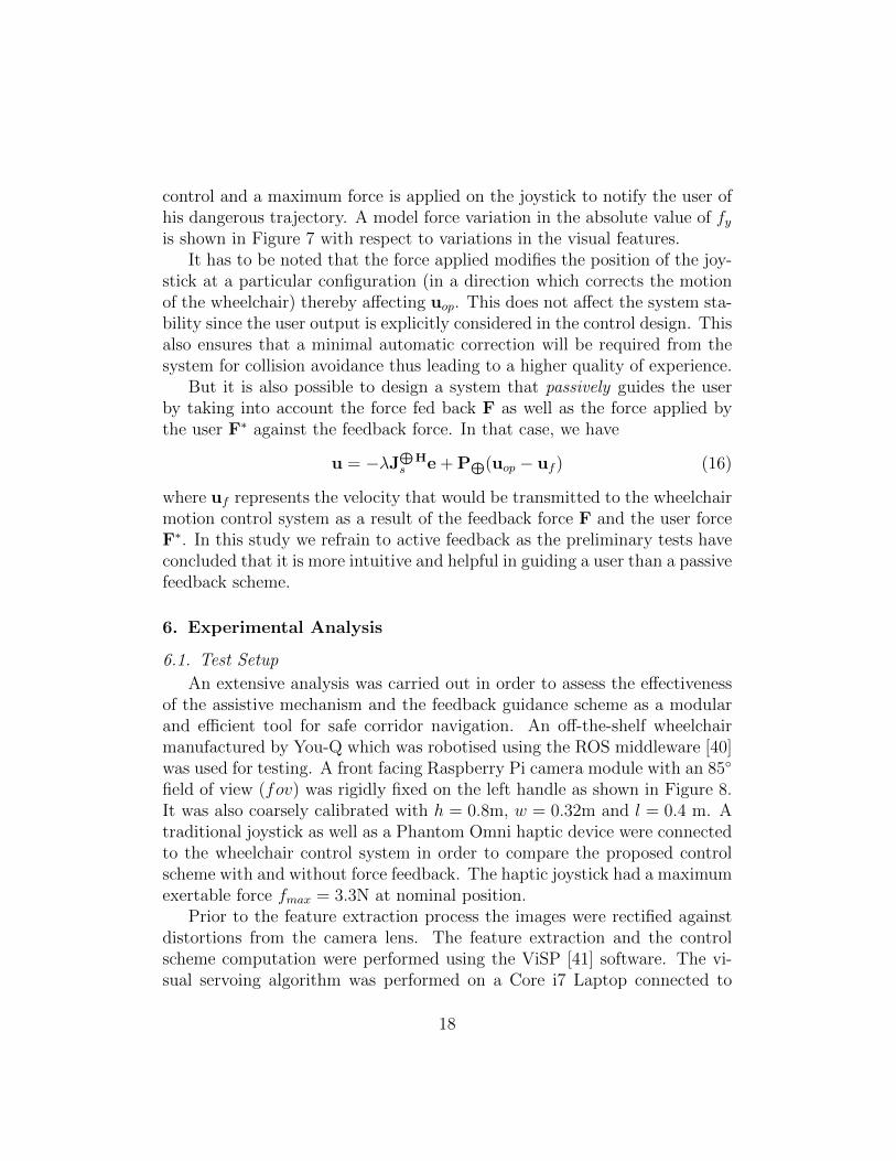
An extensive analysis was carried out in order to assess the effectivenessof the assistive mechanism and the feedback guidance scheme as a modularand efficient tool for safe corridor navigation. An off-the-shelf wheelchairmanufactured by You-Q which was robotised using the ROS middleware [40]was used for testing. A front facing Raspberry Pi camera module with an 85◦
field of view (fov) was rigidly fixed on the left handle as shown in Figure 8.It was also coarsely calibrated with h = 0.8m, w = 0.32m and l = 0.4 m. Atraditional joystick as well as a Phantom Omni haptic device were connectedto the wheelchair control system in order to compare the proposed controlscheme with and without force feedback. The haptic joystick had a maximumexertable force fmax = 3.3N at nominal position.
Prior to the feature extraction process the images were rectified againstdistortions from the camera lens. The feature extraction and the controlscheme computation were performed using the ViSP [41] software. The vi-sual servoing algorithm was performed on a Core i7 Laptop connected to
18
Traditional Joystick
Figure 8: Wheelchair test platform
the wheelchair control system using Ethernet. For ground truth estimationand visualisation purposes, the wheelchair had been equipped with a laserrange finder. This laser range finder was used neither in the visual featureextraction process nor in the control law. It only acted as a validation tool.
An analysis of the convergence and stability of the visual servoing taskfor corridor following is presented in [27]. Experimental validation is alsopresented where a wheelchair equipped with a single monocular camera isused to autonomously follow a corridor using the features detailed in Section4.
Now to be able to perform experiments using the control law proposed inthe present work, the parameters to be determined include the boundariesof the activation intervals (i.e x+f , xs+f , x−f , xs−f , θ+m, θs+m , θ−m and θs−m ), thecontrol gain λ and the factor α (see Eqn. (14)).
x+f , xs+f , x−f , xs−f are directly dependent to the field of view (fov) of thecamera. In our setup, the maximum and minimun possible values of xf arerespectively equal to tan(fov/2) ≈ 0.916 and − tan(fov/2) ≈ −0.916. Underthese constraints, we chose x+f = 0.9 and x−f = −0.9 to ensure the visibilityof the vanishing point. As the visual feature extraction algorithm needs todetect both floor/wall boundary lines, we chose xs+f = 0.3 and xs−f = −0.3,to ensure the visibility of these features.
θ+m, θs+m , θ−m and θs−m are directly dependent to the width of the cor-ridor used during the experimentation. The width of the corridor Wcor
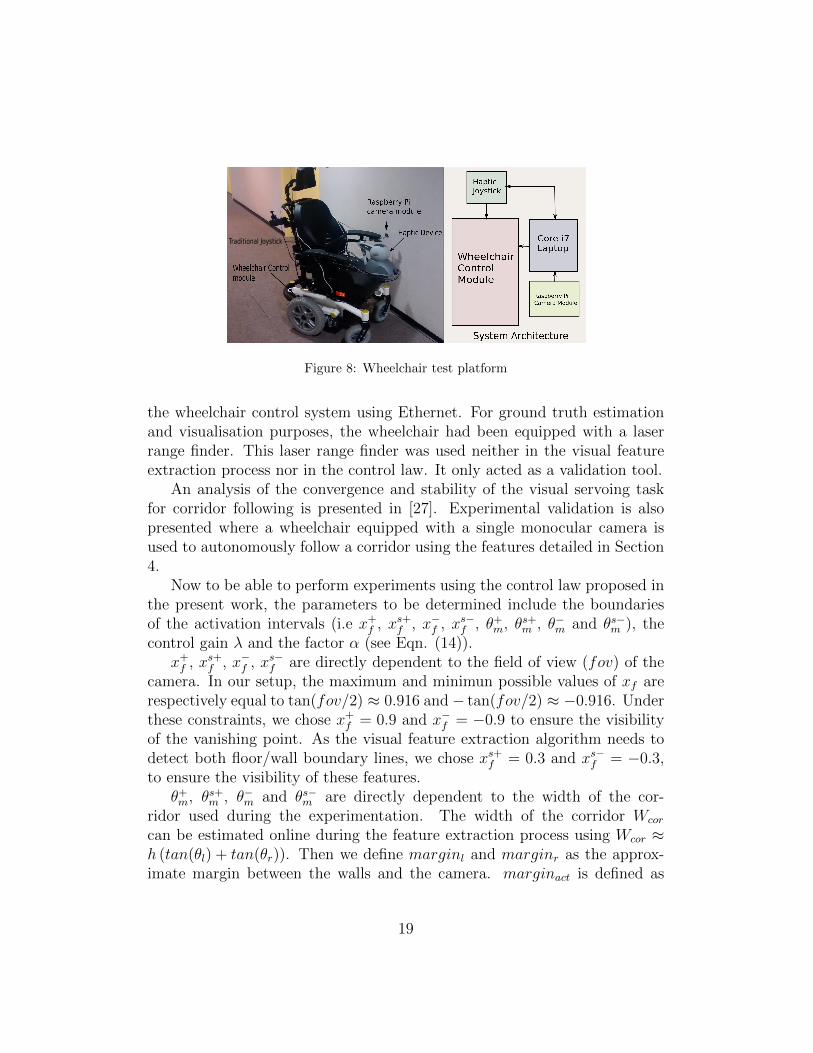
can be estimated online during the feature extraction process using Wcor ≈h (tan(θl) + tan(θr)). Then we define marginl and marginr as the approx-imate margin between the walls and the camera. marginact is defined as
19
marginact
marginact
Wcor
marginl
marginr
Figure 9: Margin definition
depicted in Figure 9. We can then determine
θ+m = arctan
(Wcor − 2marginr
h
)(17)
θs+m = arctan
(Wcor−2marginr−2marginact
h
)
θ−m = arctan
(2marginl −Wcor
h
)(18)
θs−m = arctan
(2marginl+2marginact−Wcor
h
)In our experiments, we choose marginl = 0.15m, marginr = 0.60m and
marginact = 0.30m and Wcor is estimated using the camera at initialisationand is kept constant for the rest of the experiments. This is done in order tonegate the effects of a varying θm interval. Finally the gain λ was empiricallydetermined and set at 0.3 and the normalizing factor α at 0.7 so that themaximum force experienced by the user is capped at 2.2N.
For analysing the full potential of the control system, a non-disableduser was asked to steer the wheelchair along corridors. Initial tests werecarried out using a traditional joystick with no feedback in order to assessthe efficiency of the automatic trajectory correction mechanism. Later testswere carried out using the haptic joystick in order to gauge the effects of forcefeedback on trajectory correction and user experience. The results presentedhere pertains to experiments carried out inside the Inria building in Rennes,France. The visual task is activated as soon as the wheelchair starts themotion and it is switched off as the user reaches the end of the corridor.
20
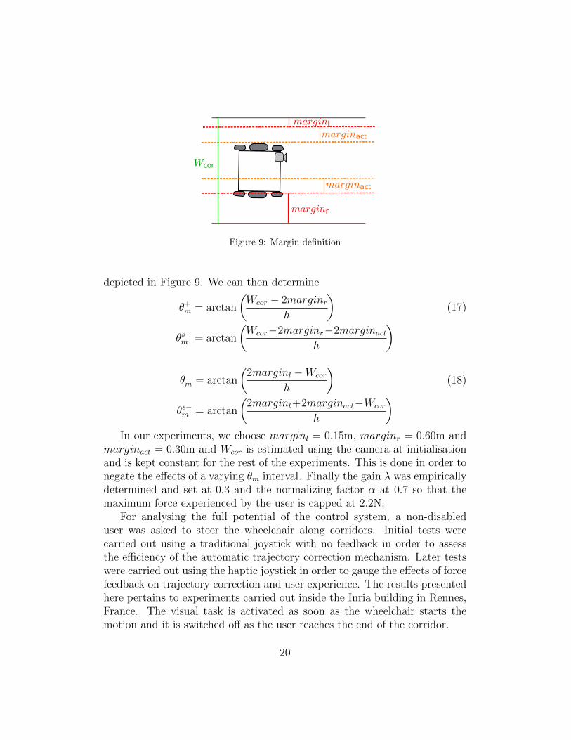
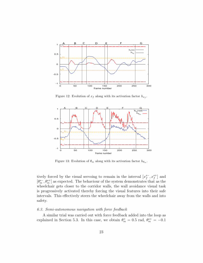
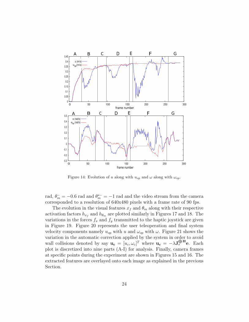
6.2. Semi-autonomous navigation without force feedbackAs the user drives the wheelchair manually in the corridor, Figures 12
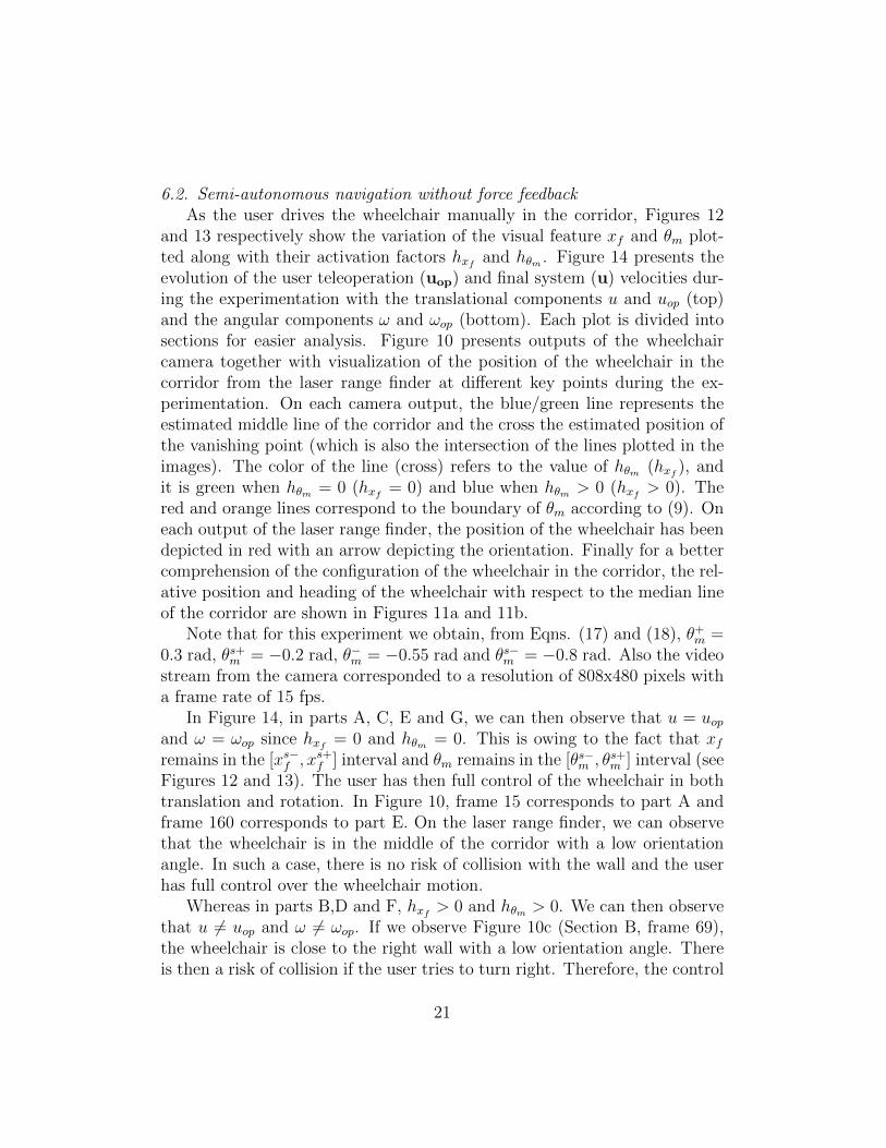
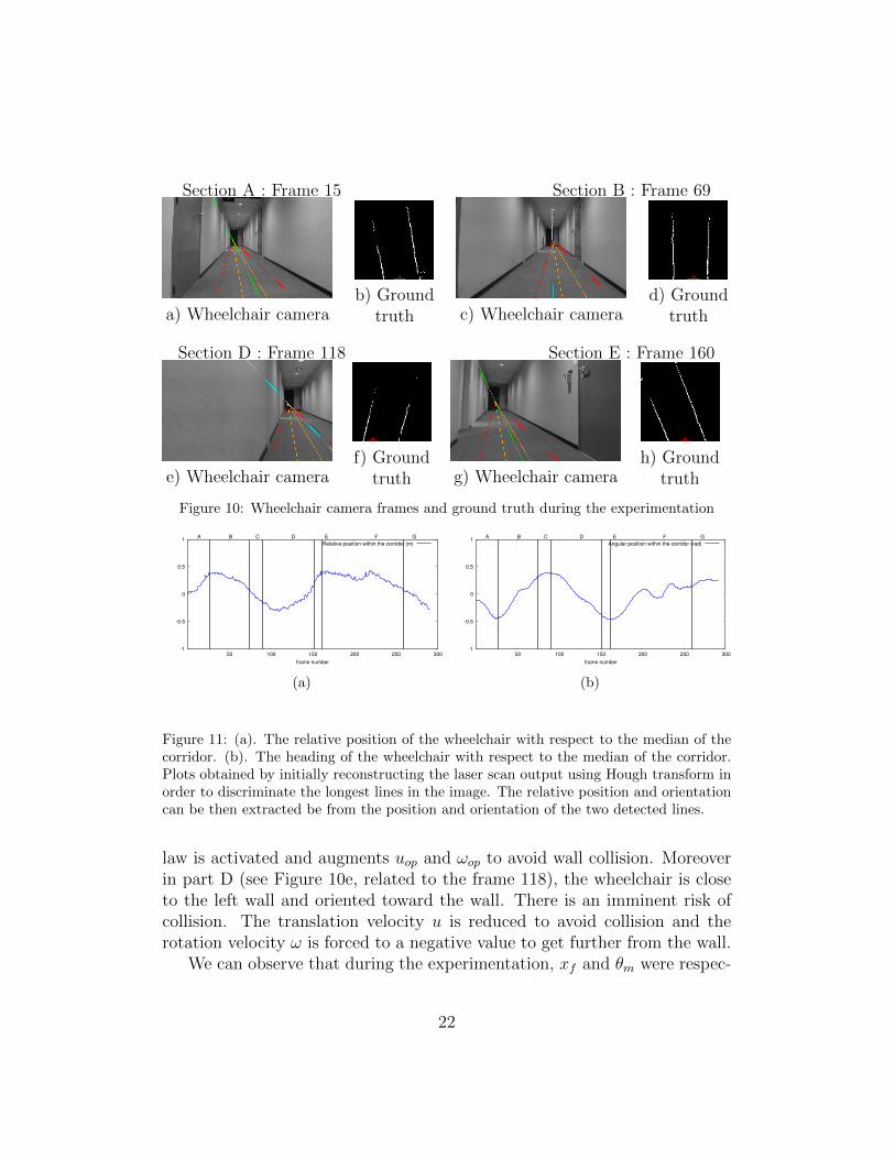
and 13 respectively show the variation of the visual feature xf and θm plot-ted along with their activation factors hxf and hθm . Figure 14 presents theevolution of the user teleoperation (uop) and final system (u) velocities dur-ing the experimentation with the translational components u and uop (top)and the angular components ω and ωop (bottom). Each plot is divided intosections for easier analysis. Figure 10 presents outputs of the wheelchaircamera together with visualization of the position of the wheelchair in thecorridor from the laser range finder at different key points during the ex-perimentation. On each camera output, the blue/green line represents theestimated middle line of the corridor and the cross the estimated position ofthe vanishing point (which is also the intersection of the lines plotted in theimages). The color of the line (cross) refers to the value of hθm (hxf ), andit is green when hθm = 0 (hxf = 0) and blue when hθm > 0 (hxf > 0). Thered and orange lines correspond to the boundary of θm according to (9). Oneach output of the laser range finder, the position of the wheelchair has beendepicted in red with an arrow depicting the orientation. Finally for a bettercomprehension of the configuration of the wheelchair in the corridor, the rel-ative position and heading of the wheelchair with respect to the median lineof the corridor are shown in Figures 11a and 11b.
Note that for this experiment we obtain, from Eqns. (17) and (18), θ+m =0.3 rad, θs+m = −0.2 rad, θ−m = −0.55 rad and θs−m = −0.8 rad. Also the videostream from the camera corresponded to a resolution of 808x480 pixels witha frame rate of 15 fps.
In Figure 14, in parts A, C, E and G, we can then observe that u = uopand ω = ωop since hxf = 0 and hθm = 0. This is owing to the fact that xfremains in the [xs−f , xs+f ] interval and θm remains in the [θs−m , θs+m ] interval (seeFigures 12 and 13). The user has then full control of the wheelchair in bothtranslation and rotation. In Figure 10, frame 15 corresponds to part A andframe 160 corresponds to part E. On the laser range finder, we can observethat the wheelchair is in the middle of the corridor with a low orientationangle. In such a case, there is no risk of collision with the wall and the userhas full control over the wheelchair motion.
Whereas in parts B,D and F, hxf > 0 and hθm > 0. We can then observethat u 6= uop and ω 6= ωop. If we observe Figure 10c (Section B, frame 69),the wheelchair is close to the right wall with a low orientation angle. Thereis then a risk of collision if the user tries to turn right. Therefore, the control
21
Section A : Frame 15 Section B : Frame 69
a) Wheelchair camerab) Ground
truth c) Wheelchair camerad) Ground
truth
Section D : Frame 118 Section E : Frame 160
e) Wheelchair cameraf) Ground
truth g) Wheelchair camerah) Ground
truth
Figure 10: Wheelchair camera frames and ground truth during the experimentation
-1
-0.5
0
0.5
1
50 100 150 200 250 300frame number
A B C D E F GRelative position within the corridor (m)
(a)
-1
-0.5
0
0.5
1
50 100 150 200 250 300frame number
A B C D E F GAngular position within the corridor (rad)
(b)
Figure 11: (a). The relative position of the wheelchair with respect to the median of thecorridor. (b). The heading of the wheelchair with respect to the median of the corridor.Plots obtained by initially reconstructing the laser scan output using Hough transform inorder to discriminate the longest lines in the image. The relative position and orientationcan be then extracted be from the position and orientation of the two detected lines.
law is activated and augments uop and ωop to avoid wall collision. Moreoverin part D (see Figure 10e, related to the frame 118), the wheelchair is closeto the left wall and oriented toward the wall. There is an imminent risk ofcollision. The translation velocity u is reduced to avoid collision and therotation velocity ω is forced to a negative value to get further from the wall.
We can observe that during the experimentation, xf and θm were respec-
22
-1
-0.5
0
0.5
1
0 50 100 150 200 250 300
xf+
xfs+
xfs-
xf-
xfhxf
(m)
frame number
A B C D E F G
Figure 12: Evolution of xf along with its activation factor hxf.
-1
-0.5
0
0.5
1
0 50 100 150 200 250 300
A B C D E F G
θm+
θms+
θms-
θm-
θmhθm
frame number
(rad)
Figure 13: Evolution of θm along with its activation factor hθm .
tively forced by the visual servoing to remain in the interval [xs−f , xs+f ] and[θs−m , θs+m ] as expected. The behaviour of the system demonstrates that as thewheelchair gets closer to the corridor walls, the wall avoidance visual taskis progressively activated thereby forcing the visual features into their safeintervals. This effectively steers the wheelchair away from the walls and intosafety.
6.3. Semi-autonomous navigation with force feedback
A similar trial was carried out with force feedback added into the loop asexplained in Section 5.3. In this case, we obtain θ+m = 0.5 rad, θs+m = −0.1
23
0
0.05
0.1
0.15
0.2
0.25
0.3
0.35
0.4
0.45
0 50 100 150 200 250 300
u (m/s)uop(m/s)
frame number
A B C D E F G
-0.3
-0.2
-0.1
0
0.1
0.2
0.3
0.4
0.5
0 50 100 150 200 250 300frame number
ω (rad/s)ωop (rad/s)
A C D E F GB
Figure 14: Evolution of u along with uop and ω along with ωop.
rad, θ−m = −0.6 rad and θs−m = −1 rad and the video stream from the cameracorresponded to a resolution of 640x480 pixels with a frame rate of 90 fps.
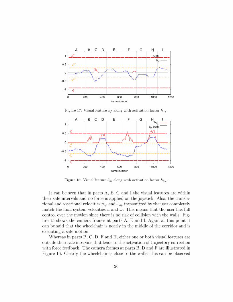
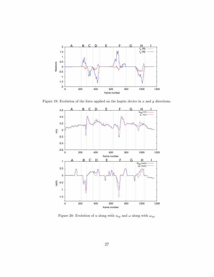
The evolution in the visual features xf and θm along with their respectiveactivation factors hxf and hθm are plotted similarly in Figures 17 and 18. Thevariations in the forces fx and fy transmitted to the haptic joystick are givenin Figure 19. Figure 20 represents the user teleoperation and final systemvelocity components namely uop with u and ωop with ω. Figure 21 shows thevariation in the automatic correction applied by the system in order to avoidwall collisions denoted by say uc = [uc, ωc]
T where uc = −λJ⊕
Hs e. Each
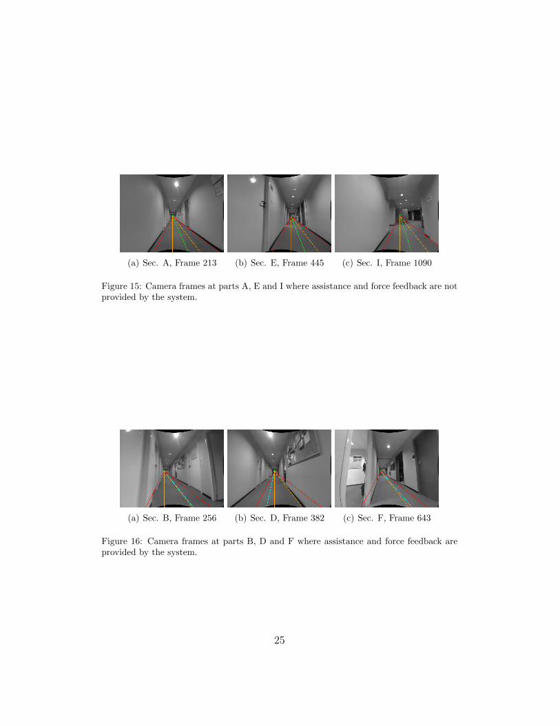
plot is discretized into nine parts (A-I) for analysis. Finally, camera framesat specific points during the experiment are shown in Figures 15 and 16. Theextracted features are overlayed onto each image as explained in the previousSection.
24
(a) Sec. A, Frame 213 (b) Sec. E, Frame 445 (c) Sec. I, Frame 1090
Figure 15: Camera frames at parts A, E and I where assistance and force feedback are notprovided by the system.
(a) Sec. B, Frame 256 (b) Sec. D, Frame 382 (c) Sec. F, Frame 643
Figure 16: Camera frames at parts B, D and F where assistance and force feedback areprovided by the system.
25
-1
-0.5
0
0.5
1
0 200 400 600 800 1000 1200frame number
hxf
xf (m)
A B C D E F G H I+xf
xf
xf
xfs+
s-
-
Figure 17: Visual feature xf along with activation factor hxf.
-1
-0.5
0
0.5
1
0 200 400 600 800 1000 1200frame number
hθm
θm (rad)
A B C D E F G H I
θm
θm
θm
θm
s+
-
+
s-
Figure 18: Visual feature θm along with activation factor hθm .
It can be seen that in parts A, E, G and I the visual features are withintheir safe intervals and no force is applied on the joystick. Also, the transla-tional and rotational velocities uop and ωop transmitted by the user completelymatch the final system velocities u and ω. This means that the user has fullcontrol over the motion since there is no risk of collision with the walls. Fig-ure 15 shows the camera frames at parts A, E and I. Again at this point itcan be said that the wheelchair is nearly in the middle of the corridor and isexecuting a safe motion.
Whereas in parts B, C, D, F and H, either one or both visual features areoutside their safe intervals that leads to the activation of trajectory correctionwith force feedback. The camera frames at parts B, D and F are illustrated inFigure 16. Clearly the wheelchair is close to the walls: this can be observed
26
-2
-1.5
-1
-0.5
0
0.5
1
1.5
2
0 200 400 600 800 1000 1200
New
tons
frame number
fx (N)fy (N)
A B C D E F G H I
Figure 19: Evolution of the force applied on the haptic device in x and y directions.
-0.6
-0.4
-0.2
0
0.2
0.4
0.6
0 200 400 600 800 1000 1200frame number
uopu
A B C D E F G H I
m/s
(m/s)
(m/s)
-1.5
-1
-0.5
0
0.5
1
0 200 400 600 800 1000 1200frame number
ωopω
A B C D E F G H I
rad/
s
(rad/s)
(rad/s)
Figure 20: Evolution of u along with uop and ω along with ωop.
27
-0.4
-0.3
-0.2
-0.1
0
0.1
0.2
0.3
0.4
0 200 400 600 800 1000 1200frame number
ωc
A B C D E F G H I
rad/
s
(rad/s)
-0.2
-0.15
-0.1
-0.05
0
0.05
0.1
0.15
0.2
0 200 400 600 800 1000 1200frame number
uc
A B C D E F G H I
m/s
(m/s)
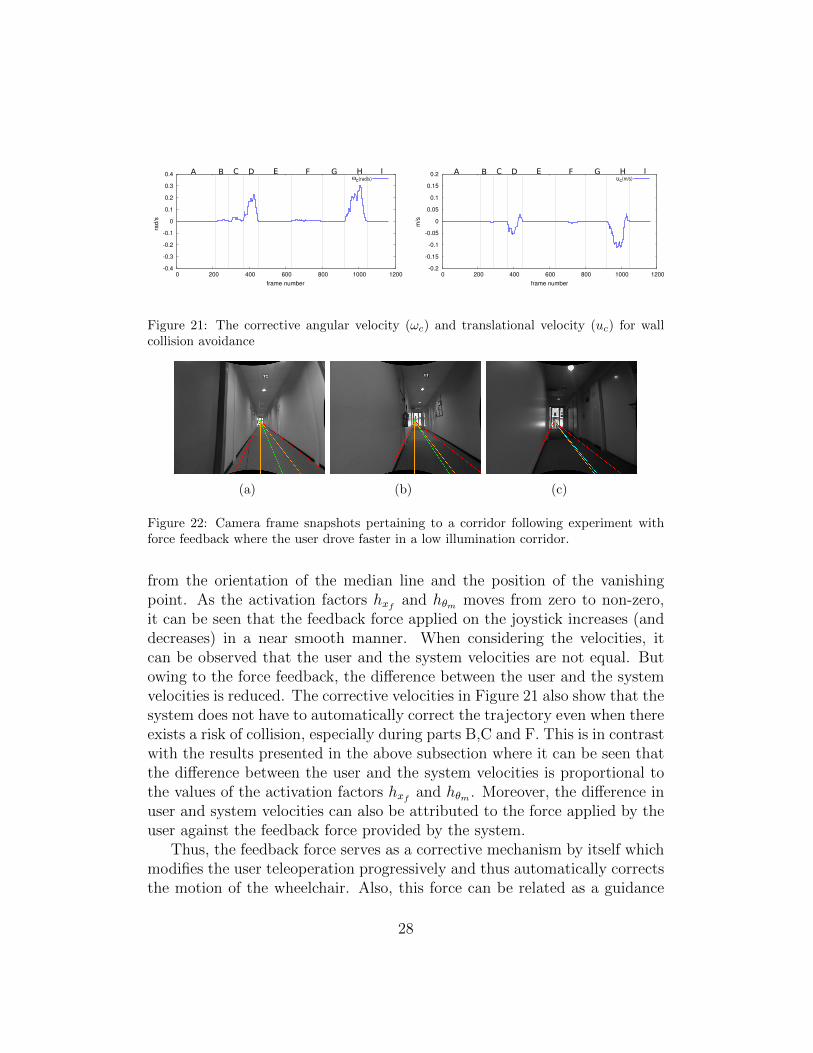
Figure 21: The corrective angular velocity (ωc) and translational velocity (uc) for wallcollision avoidance
(a) (b) (c)
Figure 22: Camera frame snapshots pertaining to a corridor following experiment withforce feedback where the user drove faster in a low illumination corridor.
from the orientation of the median line and the position of the vanishingpoint. As the activation factors hxf and hθm moves from zero to non-zero,it can be seen that the feedback force applied on the joystick increases (anddecreases) in a near smooth manner. When considering the velocities, itcan be observed that the user and the system velocities are not equal. Butowing to the force feedback, the difference between the user and the systemvelocities is reduced. The corrective velocities in Figure 21 also show that thesystem does not have to automatically correct the trajectory even when thereexists a risk of collision, especially during parts B,C and F. This is in contrastwith the results presented in the above subsection where it can be seen thatthe difference between the user and the system velocities is proportional tothe values of the activation factors hxf and hθm . Moreover, the difference inuser and system velocities can also be attributed to the force applied by theuser against the feedback force provided by the system.
Thus, the feedback force serves as a corrective mechanism by itself whichmodifies the user teleoperation progressively and thus automatically correctsthe motion of the wheelchair. Also, this force can be related as a guidance
28
-1
-0.5
0
0.5
1
0 100 200 300 400 500 600
m
frame number
hxfxf (m)
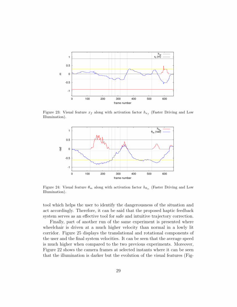
Figure 23: Visual feature xf along with activation factor hxf(Faster Driving and Low
Illumination).
-1
-0.5
0
0.5
1
0 100 200 300 400 500 600
rad
frame number
hθm
θm (rad)
Figure 24: Visual feature θm along with activation factor hθm (Faster Driving and LowIllumination).
tool which helps the user to identify the dangerousness of the situation andact accordingly. Therefore, it can be said that the proposed haptic feedbacksystem serves as an effective tool for safe and intuitive trajectory correction.
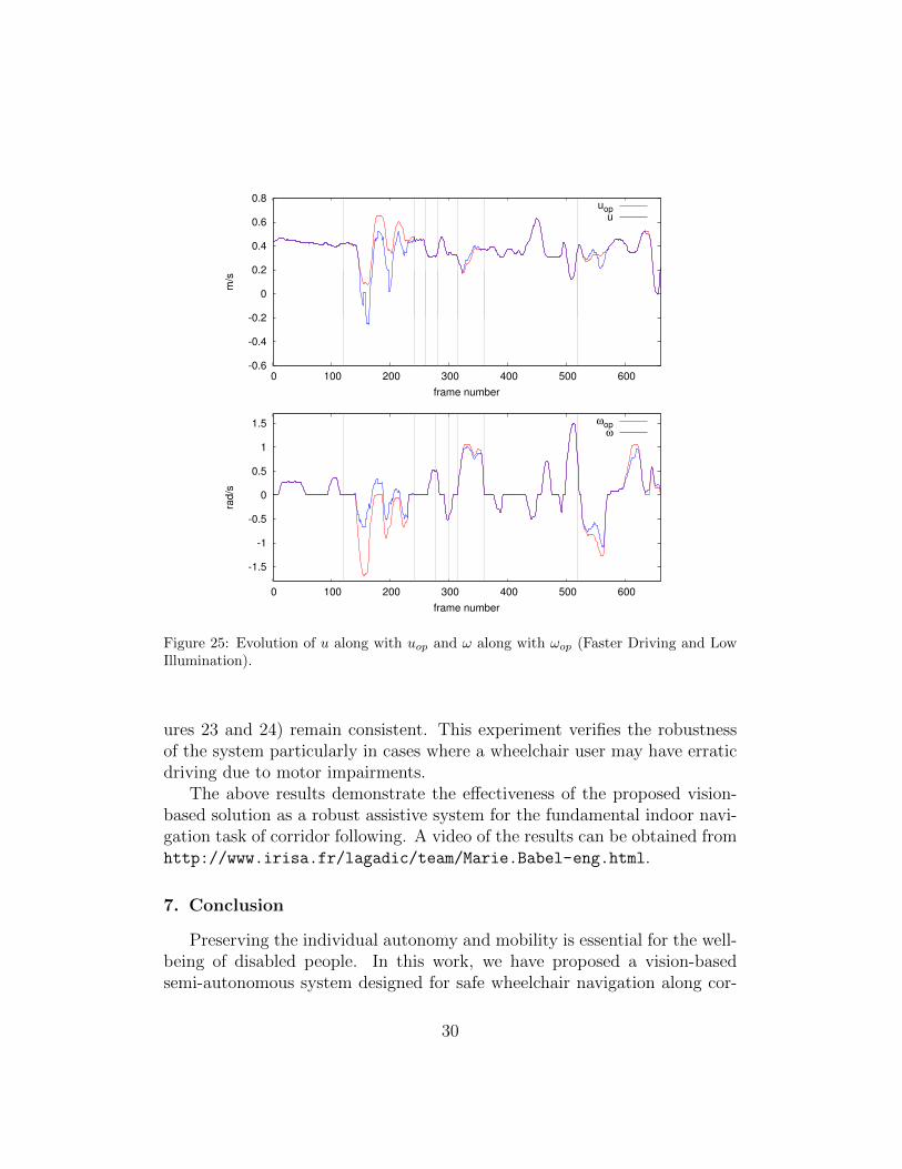
Finally, part of another run of the same experiment is presented wherewheelchair is driven at a much higher velocity than normal in a lowly litcorridor. Figure 25 displays the translational and rotational components ofthe user and the final system velocities. It can be seen that the average speedis much higher when compared to the two previous experiments. Moreover,Figure 22 shows the camera frames at selected instants where it can be seenthat the illumination is darker but the evolution of the visual features (Fig-
29
-0.6
-0.4
-0.2
0
0.2
0.4
0.6
0.8
0 100 200 300 400 500 600
m/s
frame number
uopu
-1.5
-1
-0.5
0
0.5
1
1.5
0 100 200 300 400 500 600
rad/s
frame number
ωopω
Figure 25: Evolution of u along with uop and ω along with ωop (Faster Driving and LowIllumination).
ures 23 and 24) remain consistent. This experiment verifies the robustnessof the system particularly in cases where a wheelchair user may have erraticdriving due to motor impairments.
The above results demonstrate the effectiveness of the proposed vision-based solution as a robust assistive system for the fundamental indoor navi-gation task of corridor following. A video of the results can be obtained fromhttp://www.irisa.fr/lagadic/team/Marie.Babel-eng.html.
7. Conclusion
Preserving the individual autonomy and mobility is essential for the well-being of disabled people. In this work, we have proposed a vision-basedsemi-autonomous system designed for safe wheelchair navigation along cor-
30
ridors. This control system relies on a collaboration between two tasks: firstthe manual steering and second wall avoidance task obtained by a dedicatedvisual servoing approach. The idea is then to correct the trajectory indi-cated by the user by servoing only the necessary degrees of freedom. Thisvisual servoing process is based on both the vanishing point and wall planedetection. A smooth transition from manual driving to assisted navigation isobtained owing to an adapted weighting function, thus avoiding discontinu-ities that can lead to unpleasant experience. Results clearly show the abilityof the approach to provide an efficient solution for wall avoiding purposes.
Moreover haptic force feedback in conjunction with the assistance wasprovided in order to notify the user of danger and guide him over to a saferzone. We observe that the guidance force serves as an automatic correc-tive mechanism which ensures minimal interference from the visual controlprocess thus leading to a better quality of experience.
Future research aims at integrating local obstacle avoidance to the systemwhile tackling other fundamental navigation problems like doorway passing.Delving into user intention analysis may also help in formulating adapted al-gorithms for vision-based wheelchair navigation assistance. A series of testswith the help of voluntary patients at a Rehabilitation Center (Pole St. He-lier, Rennes, France) is also underway.
AcknowledgementThis work is supported by the Inria large-scale initiative action Personally
Assisted Living (PAL). The authors would like to thank Daniel Guillard andLuc Le Pape from Ergovie, and Eric Bazin from INSA Rennes.
References
[1] B. Krieg-Bruckner, D. Crombie, B. Gersdorf, A. Juptner, M. Lawo,C. Mandel, A. B. Martınez, T. Rofer, C. Stahl, Challenges for Indoor andOutdoor Mobility Assistance, Technik fur ein selbstbestimmtes Leben.
[2] A. Kokosy, T. Floquet, G. Howells, H. Hu, M. Pepper, C. Donze, SYSI-ASS An Intelligent Powered Wheelchair, International Conference onSystems and Computer Science, 2012.
[3] L. Nordenfelt, Dignity in Care for Older People, Wiley-Blackwell, 2009.
[4] T. Gomi, A. Griffith, Developing intelligent wheelchairs for the hand-icapped, Assistive Technology and Artificial Intelligence, Vol. 1458 of
31
Lecture Notes in Computer Science, Springer Berlin Heidelberg, 1998,pp. 150–178.
[5] S. P. Levine, D. A. Bell, L. A. Jaros, R. C. Simpson, Y. Koren, J. Boren-stein, The NavChair Assistive Wheelchair Navigation System, IEEETransactions on Rehabilitation Engineering, 1999, pp. 443–451.
[6] E. Demeester, E. EB Vander Poorten, A. Huntemann, J. De Schutter,Wheelchair navigation assistance in the FP7 project radhar: Objectivesand current state, IROS Workshop on Progress, Challenges and FuturePerspectives in Navigation and Manipulation Assistance for RoboticWheelchairs, 2012.
[7] B. D. Argall, Modular and Adaptive Wheelchair Automation, Proceed-ings of the International Symposium on Experimental Robotics, Mar-rakech, Morrocco, 2014.
[8] R. A. M. Braga, M. Petry, A. P. Moreira, L. P. Reis, Intellwheels: ADevelopment PlatForm for intelligent wheelchairs for disabled people,5th International Conference on Informatics in Control, Automation andRobotics, 2008, pp. 115–121.
[9] F. Galan, M. Nuttin, E. Lew, P. W. Ferrez, G. Vanacker, J. Philips,J. D. R. Millan, A brain-actuated wheelchair: asynchronous and non-invasive Brain-computer interfaces for continuous control of robots.,Clinical neurophysiology, 119 (9), 2008, pp. 2159–2169.
[10] T. Carlson, J. del R. Millan, Brain-Controlled Wheelchairs: A RoboticArchitecture, IEEE Robotics & Automation Magazine, 20 (1), 2013, pp.65–73.
[11] S. Thrun, et al., Robotic mapping: A survey, Exploring artificial intel-ligence in the new millennium, 2002, pp. 1–35.
[12] N. Winters, J. Gaspar, G. Lacey, J. Santos-Victor, Omni-directionalvision for robot navigation, Proceedings of IEEE Workshop on Omnidi-rectional Vision, 2000.
[13] R. Carelli, C. Soria, O. Nasisi, R. Freire, Stable agv corridor navigationwith fused vision-based control signals, 28th Annual Conference of theIndustrial Electronics Society, Vol. 3, 2002, pp. 2433–2438.
32
[14] J. Toibero, C. Soria, F. Roberti, R. Carelliz, P. Fiorini, Switching visualservoing approach for stable corridor navigation, International Confer-ence on Advanced Robotics, 2009, pp. 1–6.
[15] R. F. Vassallo, H. J. Schneebeli, J. Santos-Victor, Visual servoing andappearance for navigation, Robotics and Autonomous Systems, 31 (12),2000, pp. 87 – 97.
[16] R. C. Simpson, D. Poirot, F. Baxter, The hephaestus smart wheelchairsystem, IEEE Transactions on Neural Systems and Rehabilitation En-gineering, 10 (2), 2002, pp. 118–122.
[17] J. Philips, J. del R. Millan, G. Vanacker, E. Lew, F. Galan, P. W.Ferrez, H. Van Brussel, M. Nuttin, Adaptive Shared Control of a Brain-Actuated Simulated Wheelchair, International Conference on Rehabili-tation Robotics, 2007, pp. 408–414.
[18] R. Simpson, S. Levine, Adaptive shared control of a smart wheelchairoperated by voice control, IEEE/RSJ International Conference on In-telligent Robot and Systems, Vol. 2, 1997, pp. 622–626.
[19] A. Escobedo, A. Spalanzani, C. Laugier, Using social cues to estimatepossible destinations when driving a robotic wheelchair, IEEE/RSJ In-ternational Conference on Intelligent Robots and Systems, 2014, pp.3299–3304.
[20] E. Vander Poorten, E. Demeester, E. Reekmans, J. Philips, A. Hunte-mann, J. De Schutter, Powered wheelchair navigation assistance throughkinematically correct environmental haptic feedback, IEEE Interna-tional Conference on Robotics and Automation, 2012, pp. 3706–3712.
[21] R. Luo, Force reflective feedback control for intelligent wheelchairs,IEEE/RSJ International Conference on Intelligent Robots and Systems,Vol. 2, 1999, pp. 918–923.
[22] L. Kitagawa, T. Kobayashi, T. Beppu, K. Terashima, Semi-autonomousobstacle avoidance of omnidirectional wheelchair by joystick impedancecontrol, IEEE/RSJ International Conference on Intelligent Robots andSystems, Vol. 4, 2001, pp. 2148–2153.
33
[23] A. Fattouh, M. Sahnoun, G. Bourhis, Force feedback joystick control of apowered wheelchair: preliminary study, IEEE International Conferenceon Systems, Man and Cybernetics, Vol. 3, 2004, pp. 2640–2645.
[24] G. Bourhis, M. Sahnoun, Assisted Control Mode for a Smart Wheelchair,International Conference on Rehabilitation Robotics, 2007, pp. 158–163.
[25] F. Chaumette, S. Hutchinson, Visual servo control, Part I: Basic ap-proaches, IEEE Robotics and Automation Magazine, 13 (4), 2006, pp.82–90.
[26] F. Pasteau, M. Babel, R. Sekkal, Corridor following wheelchair by visualservoing, IEEE/RSJ International Conference on Intelligent Robots andSystems, 2013, pp. 590–595.
[27] F. Pasteau, V. Karakkat-Narayanan, M. Babel, F. Chaumette, A vi-sual servoing approach for autonomous corridor following and doorwaypassing in a wheelchair, Robotics and Autonomous Systems, 2015.
[28] F. Pasteau, A. Krupa, M. Babel, Vision-based assistance for wheelchairnavigation along corridors, IEEE International Conference on Roboticsand Automation, 2014.
[29] C. Rother, A new approach for vanishing point detection in architecturalenvironments, 11th British Machine Vision Conference, 2000, pp. 382–391.
[30] K. Boulanger, K. Bouatouch, S. Pattanaik, ATIP: A Tool for 3D Nav-igation inside a Single Image with Automatic Camera Calibration, EGUK conference, 2006.
[31] R. Grompone von Gioi, J. Jakubowicz,J.-M. Morel, G. Randall, LSD: aLine Segment Detector, Image Processing On Line, 2012.
[32] R. Sekkal, F. Pasteau, M. Babel, B. Brun, I. Leplumey, Simple Monoc-ular door detection and tracking, IEEE International Conference on Im-age Processing, 2013.
[33] K. Ok, D.-N. Ta, F. Dellaert, Vistas and wall-floor intersection features- enabling autonomous flight in man-made environments, Workshop onVisual Control of Mobile Robots, 2012.
34
[34] E. Delage, H. Lee, A. Ng, A dynamic bayesian network model for au-tonomous 3d reconstruction from a single indoor image, IEEE Confer-ence on Computer Vision and Pattern Recognition, Vol. 2, 2006, pp.2418 – 2428.
[35] O. Kermorgant, F. Chaumette, Combining IBVS and PBVS to ensurethe visibility constraint, IEEE/RSJ International Conference on Intelli-gent Robots and Systems, 2011, pp. 2849–2854.
[36] T. Li, O. Kermorgant, A. Krupa, Maintaining visibility constraints dur-ing tele-echography with ultrasound visual servoing, IEEE InternationalConfernence on Robotics and Automation, 2012, pp. 4856–4861.
[37] N. Mansard, F. Chaumette, Task Sequencing for High-Level Sensor-Based Control, IEEE Transactions on Robotics, 23 (1), 2007, pp. 60–72.
[38] N. Mansard, A. Remazeilles, F. Chaumette, Continuity of Varying-Feature-Set Control Laws, IEEE Transactions on Automatic Control,54 (11), 2009, pp. 2493–2505.
[39] C. Samson, B. Espiau, M. L. Borgne, Robot Control: The Task FunctionApproach, Oxfored University Press, 1991.
[40] M. Quigley, K. Conley, B. Gerkey, J. Faust, T. Foote, J. Leibs,R. Wheeler, A. Y. Ng, Ros: an open-source robot operating system,ICRA workshop on open source software, 3 (3.2), 2009.
[41] E. Marchand, F. Spindler, F. Chaumette, ViSP for visual servoing: ageneric software platform with a wide class of robot control skills, IEEERobotics and Automation Magazine, 12 (4), 2005, pp. 40–52.