Electronic Letters on Computer Vision and Image Analysis 11(1):54-67, 2012 Vision Based Object Recognition and Localisation by a Wireless Connected Distributed Robotic Systems M Shuja Ahmed, Reza Saatchi and Fabio Caparrelli Material and Engineering Research Institute, Sheffield Hallam University, Sheffield, United Kingdom Received 7 th Feb 2012; accepted 13 th Oct 2012 Abstract Object recognition and localisation are important processes in computer vision and robotics. Advances in computer vision have resulted in many object recognition techniques, but most of them are computation- ally very intensive and require robots with powerful processing systems. For small robots, these techniques are not applicable because of the constraints of execution time. In this study, an optimised implementation of SURF based recognition technique is presented. Suitable image pre-processing techniques were devel- oped which reduced the recognition time on small robots with limited processing resources. The recognition time was reduced from 39 seconds to 780 milliseconds. This recognition technique was adopted by a team of small robots which were given prior training to search for objects of interest in the environment. For the localisation of the robots and objects a new template, designed for passive markers based tracking, was introduced. These markers were placed on the top of each robot and they were tracked by the two ceil- ing mounted cameras. The information from both sources, that is ceiling mounted cameras and team of robots, was used collectively to localise the objects in the environment. The objects were localised with an error ranging from 2.8cm to 5.2cm from their actual positions in the test arena which has the dimensions of 150x163cm. Key Words: Object Recognition, Localisation, Multi-camera tracking. 1 Introduction In robotics, object recognition and localisation are considered essential operations. In most robotic applications, robots are required to search and recognise the target objects in an environment. They also need to determine their own positions. In an earlier research, the use of a single robot was made for such objectives [1], but in those cases, the malfunctioning of the robot can result in the failure of the complete mission. In the latest research, the trend is shifting towards Network Connected Distributed Robotic Systems [2] [3], where the provision of multiple robots is made for the collective achievement of the common objective efficiently. In such systems, the tasks are distributed over a network of computing units or robots, where each unit has defined responsibilities which contribute to achieve a common objective. This approach also reduces the possibility of mission failure by providing redundancy in the number of robot units. To make such systems cost effective, the embedded robotic platform with limited memory and processing resources are deployed. The problem of using Network Correspondence to: <m [email protected]> Recommended for acceptance by <Xavier Otazu> ELCVIA ISSN:1577-5097 Published by Computer Vision Center / Universitat Aut` onoma de Barcelona, Barcelona, Spain
Transcript
Electronic Letters on Computer Vision and Image Analysis 11(1):54-67, 2012
Vision Based Object Recognition and Localisation by a WirelessConnected Distributed Robotic Systems
M Shuja Ahmed, Reza Saatchi and Fabio Caparrelli
Material and Engineering Research Institute, Sheffield Hallam University, Sheffield, United Kingdom
Received 7th Feb 2012; accepted 13th Oct 2012
Abstract
Object recognition and localisation are important processes in computer vision and robotics. Advancesin computer vision have resulted in many object recognition techniques, but most of them are computation-ally very intensive and require robots with powerful processing systems. For small robots, these techniquesare not applicable because of the constraints of execution time. In this study, an optimised implementationof SURF based recognition technique is presented. Suitable image pre-processing techniques were devel-oped which reduced the recognition time on small robots with limited processing resources. The recognitiontime was reduced from 39 seconds to 780 milliseconds. This recognition technique was adopted by a teamof small robots which were given prior training to search for objects of interest in the environment. Forthe localisation of the robots and objects a new template, designed for passive markers based tracking, wasintroduced. These markers were placed on the top of each robot and they were tracked by the two ceil-ing mounted cameras. The information from both sources, that is ceiling mounted cameras and team ofrobots, was used collectively to localise the objects in the environment. The objects were localised with anerror ranging from 2.8cm to 5.2cm from their actual positions in the test arena which has the dimensions of150x163cm.
In robotics, object recognition and localisation are considered essential operations. In most robotic applications,robots are required to search and recognise the target objects in an environment. They also need to determinetheir own positions. In an earlier research, the use of a single robot was made for such objectives [1], but in thosecases, the malfunctioning of the robot can result in the failure of the complete mission. In the latest research,the trend is shifting towards Network Connected Distributed Robotic Systems [2] [3], where the provision ofmultiple robots is made for the collective achievement of the common objective efficiently. In such systems, thetasks are distributed over a network of computing units or robots, where each unit has defined responsibilitieswhich contribute to achieve a common objective. This approach also reduces the possibility of mission failureby providing redundancy in the number of robot units. To make such systems cost effective, the embeddedrobotic platform with limited memory and processing resources are deployed. The problem of using Network
Recommended for acceptance by <Xavier Otazu>ELCVIA ISSN:1577-5097Published by Computer Vision Center / Universitat Autonoma de Barcelona, Barcelona, Spain
M. Shuja / Electronic Letters on Computer Vision and Image Analysis 11(1):54-67; 2012 55
Connected, Distributed, small size Robot Systems for Object Recognition and Localisation can be broken downinto three parts. These are Object recognition, localisation and information sharing across network connecteddistributed small size robotic systems. These tasks should be performed while keeping in view that the roboticsystem deployed have limited on-board resources (i.e., memory and processing resources).
In computer vision field, object recognition is considered as one of the most complex problems. It presentsseveral challenges such as, view point changes, intensity variations, occlusions and background clutter. Theprovision of this functionality in embedded robotics applications introduces an important challenge given bythe constraints for execution time (i.e., computational complexity) [4]. In real world systems, consideringthe processing demands of the vision algorithms, the robots are equipped with high processing systems. Butsuch systems are not suitable for multi-robotic operations, as a single system alone is very costly and this inturn increases the overall cost of the deployed system. To reduce the cost, small size robots are used, butthey have limited on-board processing and memory resources. For high performance robotic systems, manycomputationally expensive object recognition techniques may be used without significant modifications. Butfor small size robots, the limited resources make the options limited and the tasks more challenging.
During the past few decades, many object recognition techniques have been developed. Some of these arecomputationally less expensive, such as “content based approaches” and “geometric approaches”, but are sensi-tive to changes in lighting conditions. Other approaches are considered more computationally expensive, (suchas context based and appearance based approaches e.g., using SIFT, SURF or PCA feature descriptors), butare found to be more flexible and show invariation to changes in scale, rotation, skew and lighting conditions.Most recent efforts are centered on appearance-based approaches [5]. A SURF based recognition for perform-ing robot navigation tasks is presented in [6], where a core2Duo- 2.66GHz processing system was used toachieve a real time performance, which made the task less challenging. In [7], the authors used a SURF basedapproach to perform traffic sign recognition in an embedded system environment. For faster recognition, theSURF features space clustering approach was used. But the system was dedicated to perform only recognitiontask. The concept of clustering the feature space is called feature space quantization in some approaches [8]and it provides significant savings in memory and thus makes the approach more suited for the implementationon embedded systems. Some researchers have used probabilistic models in conjunction with the SURF featurebased approach to perform robot localisation and mapping [9]. In comparison to this, in some approaches [10],the authors relied on Harris features in place of SURF features to reduce the computation time. The author alsoused Partially Observable Markov Decision Process (POMDP) probabilistic methods to track the probabilitydistribution of the robot where-about and to essentially localising them. In order to perform this, a high pro-cessing system was utilised. In [11], Harris features were used together with SIFT descriptors and then SupportVector Machines (SVM) was used for classification. The use of Harris features together with SIFT made theapproach computationally very heavy, even for high processing systems.
It is to be noted that, in most studies, a high performance system is used for performing recognition. So inspite of excellent results achieved with these recognition techniques, when it comes to small embedded roboticplatforms, the bottle-neck of the slow rate of visual information processing forces the researchers to make hugecompromises with the recognition performance and switch to computationally less expensive algorithms. In onepart of this research, we suggest techniques which make the computationally expensive but efficient recognitionapproaches applicable for small robotic platforms. In this study, we focus on efficiently applying appearancebased approaches to object recognition. For recognising the objects of interest using limited onboard resources,an optimised implementation of SURF features based recognition algorithm is presented. To achieve onboardprocessing of SURF feature based algorithm, some image pre-processing steps are defined. These image pre-processing reduces the amount of data to be processed by the computationally heavy SURF algorithm. Anew approach to switch between different image resolutions is also presented which increases the recognitionperformance significantly.
The second problem addressed in this research is to localise the robots and also the objects of interest inthe environment, once they are found and recognised by the network connected robots. So before localisingthe object of interest, it is necessary to localise the robots first. In a multi-robotic system, localisation is an
56 M. Shuja / Electronic Letters on Computer Vision and Image Analysis 11(1):54-67; 2012
important research topic as it gives the location awareness to the robots. Determining the localisation informa-tion using radio frequency identification (RFID) [14] tags are popular techniques, but the advances in machinevision field have shifted the research trend towards vision based tracking and localisation systems as a singlevision sensor can be used to solve many tasks. In machine vision field, a number of algorithms have been devel-oped which locate objects in the images captured in the natural environment (i.e., unconstrained images). Thevision processing demands of these algorithms are normally high due to the complexity of the environment. Ifthere is a large number of objects to localise, then markers based techniques can be adopted [15], especiallywhen working in an indoor robotic environment. Markers used in these techniques can be identified as active orpassive. Active marker based approaches are computationally less expensive and can be easily run in real time.But their major drawback is energy consumption as they require power to become functional. An active markersolution can be very expensive as presented in [16], where each robot is required to be equipped with a camerafacing vertically upward to detect infrared sensors attached to the ceiling. For small number of robots, activemarker solution can be used. But, if the number of robots is large, then it does not remain an energy efficientsolution, so in this case the passive marker technique is more suitable. The passive markers solution is verycost effective, but the most challenging issue is their robust detection capability. For their reliable detection,they are required to be carefully designed such that their appearance in the environment remains prominent.A use of passive markers approach is presented in [17], where the author has demonstrated its use to identifyand track the robots playing in a robotic soccer team. No colour information is used in designing the markers,which reduces the possible number of robots which may be identified. In [18], an open source implementationof a Marker-based vision system, called Cantag, is described. Cantag represents the markers in the binary formand adopts very complex image processing techniques for their detection. As the density of binary informationstored in the Cantag binary marker is high, so it is likely that it provides false results if the marker is viewedfrom a large distance and at a sharp angle. So, in a multi-robotic environment, marker based technique, whichprovides enough information to identify the robots robustly with less complicated algorithm would be preferred.
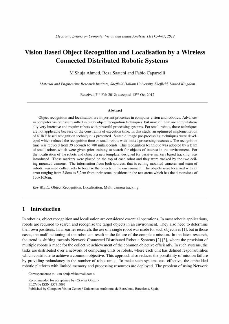
In this study the robot localisation problem is addressed using the information from two ceiling mountedcameras. The approach presented was found to be very cost effective and robust for localisation and tracking.Newly designed passive markers, which use colour information to code robots’ identities (i.e., ID) and orienta-tions, are used on the top of each robot. These markers were tracked by the two ceiling mounted cameras whichgave a collective view of the robots’ working arena. All robots were wirelessly connected with each other andalso with the server which was further connected to the two ceiling mounted cameras. The robots search for theobjects of interest collectively and kept on updating each other and also the server about the object’s identities.For localising the objects of interest, a new approach, which is easy to implement on small robots, is addressed.After recognising the objects of interest, the robots informed the server about the distance at which the objectwas located from the robot’s current position. The server uses the robot’s localisation information obtainedfrom the ceiling cameras together with the “distance to object” information sent from the robot to finally lo-calise the objects in the arena. The manner all the robots and the ceiling mounted cameras were connected,using wireless and wired medium respectively, with the server system is shown in Figure 1.
2 Methodology
2.1 On-board Object Recognition
As indicated in the Introduction Section, in one part of this study, the strengths of computationally expensiveappearance based recognition approaches are explored and they are made to run efficiently on a group of smallrobots. As described in [12] [13], the SURF feature based recognition approach is found to be the fastest tocompute and appears to be more favorable for implementation on embedded systems. There are a number ofopen source implementations of SURF algorithm, such as OpenCV [20] and OpenSURF [21]. In this study,OpenSURF implementation was used as a reference as it is faster and better optimised as compared to itsOpenCV implementation. The target hardware is also an important factor as it strongly influences the method
M. Shuja / Electronic Letters on Computer Vision and Image Analysis 11(1):54-67; 2012 57
Figure 1: Group of robots performing collective search to find and localise the objects of interest.
adopted to solve the object recognition and localisation problem. For this purpose, a group of SRV robots bySurveyor Corporation [23] were used. The onboard processing unit is a 16/32-bit Blackfin BF537E processor.uClinux (micro controller linux), which is a popular operating system customized for embedded systems, wasused as the on-board operating system. Code compilation was performed using GNU cross compilers on aLinux based development platform. The image processing achieved rate, when OpenSURF was cross compiledand ran on the Blackfin processor, was 1 frame in 33 seconds, while the image resolution was set to 320x240pixels. The reason for this slow processing was twofolds. One was the computationally expensive nature of thealgorithm and second was that the algorithm performs many floating point operations and the target Blackfinprocessor lacks the floating point unit (FPU). To reduce the execution time and also to increase the performanceof the algorithm to recognise the objects lying far from the robots, the following optimisation tasks were carriedout.
• Processor specific optimisation was performed to reduce execution time.
• Images were pre-processed to reduce the amount of data to process.
• Multi-resolution analysis operation was performed.
These tasks are explained in the following sections.
2.1.1 Processor Specific Optimisation
To perform processor specific optimisation, the SURF algorithm was coded such that it exploited the architec-tural advantages of the target embedded system. For example, the Blackfin is a fixed point processor, so thefloating point arithmetic operation should be avoided. A further limitation on the fixed point operations is posedby the uClinux operating system as it allows only 1.31 fixed point operations. This also makes it necessary tonormalise the fixed point data at every stage in the program flow in order to guarantee that it lies in the rangeof -0.9 to +0.9, otherwise erroneous results will occur.
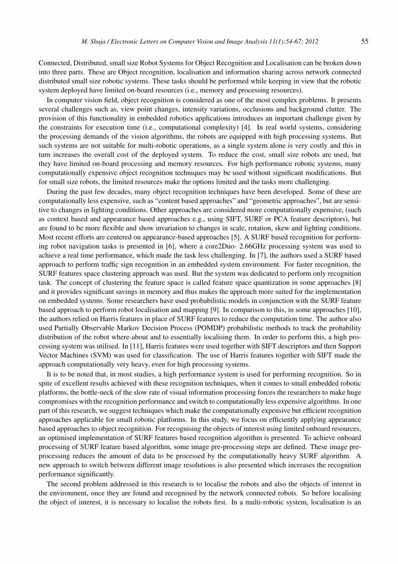
In general, the Blackfin code optimisation can be performed in three different phases, i.e., Compiler optimi-sation, System optimisation and Assembly optimisation [22]. Following these optimisations, the improvement
58 M. Shuja / Electronic Letters on Computer Vision and Image Analysis 11(1):54-67; 2012
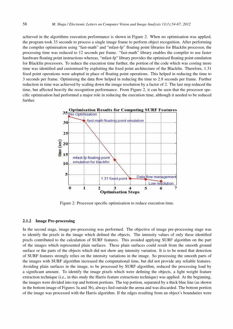
achieved in the algorithms execution performance is shown in Figure 2. When no optimisation was applied,the program took 33 seconds to process a single image frame to perform object recognition. After performingthe compiler optimisation using “fast-math” and “mfast-fp” floating point libraries for Blackfin processor, theprocessing time was reduced to 12 seconds per frame. “fast-math” library enables the compiler to use fasterhardware floating point instructions whereas, “mfast-fp” library provides the optimised floating point emulationfor Blackfin processors. To reduce the execution time further, the portion of the code which was costing moretime was identified and customised by exploiting the fixed point architecture of the Blackfin. Therefore, 1.31fixed point operations were adopted in place of floating point operations. This helped in reducing the time to3 seconds per frame. Optimising the data flow helped in reducing the time to 2.8 seconds per frame. Furtherreduction in time was achieved by scaling down the image resolution by a factor of 2. The last step reduced thetime, but affected heavily the recognition performance. From Figure 2, it can be seen that the processor spe-cific optimisation had performed a major role in reducing the execution time, although it needed to be reducedfurther.
Figure 2: Processor specific optimisation to reduce execution time.
2.1.2 Image Pre-processing
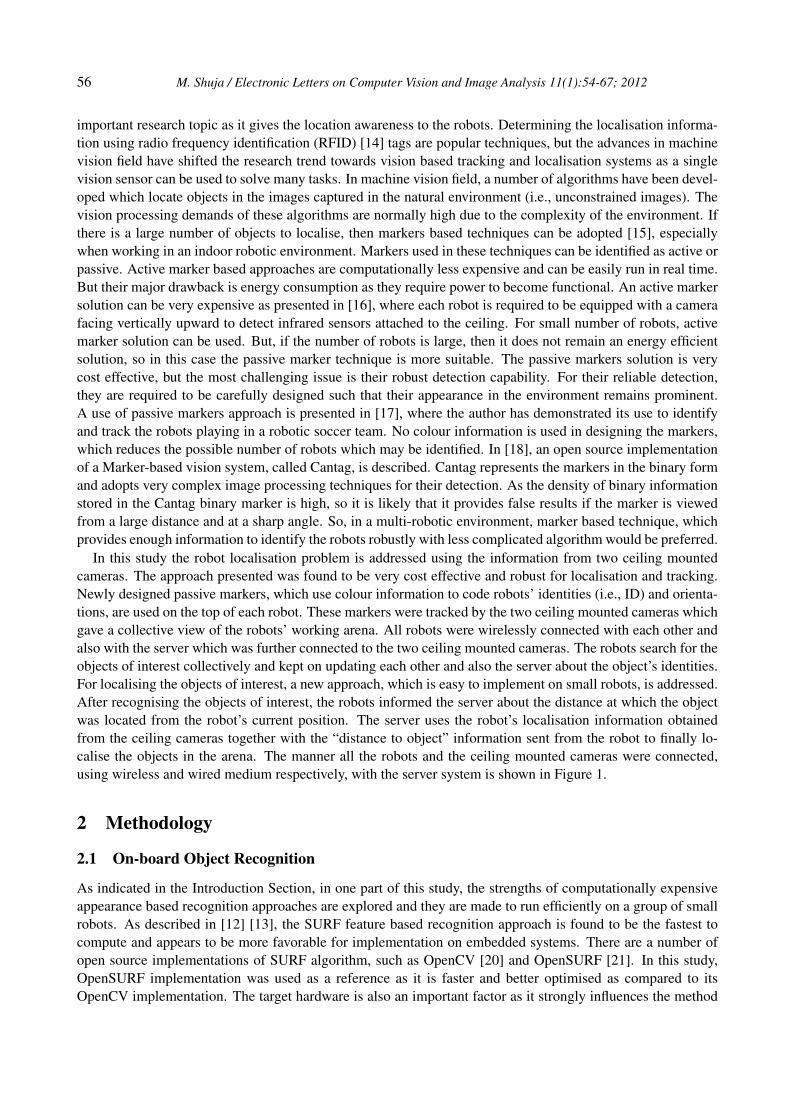
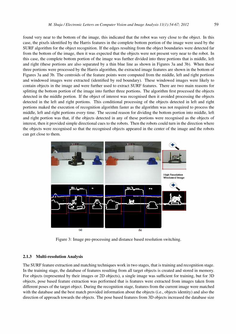
In the second stage, image pre-processing was performed. The objective of image pre-processing stage wasto identify the pixels in the image which defined the objects. The intensity values of only these identifiedpixels contributed to the calculation of SURF features. This avoided applying SURF algorithm on the partof the images which represented plain surfaces. These plain surfaces could result from the smooth groundsurface or the parts of the objects which did not show any intensity variation. It is to be noted that detectionof SURF features strongly relies on the intensity variations in the image. So processing the smooth parts ofthe images with SURF algorithm increased the computational time, but did not provide any reliable features.Avoiding plain surfaces in the image, to be processed by SURF algorithm, reduced the processing load bya significant amount. To identify the image pixels which were defining the objects, a light weight featureextraction technique (i.e., in this study the Harris feature extractions technique) was applied. At the beginning,the images were divided into top and bottom portions. The top portion, separated by a thick blue line (as shownin the bottom image of Figures 3a and 3b), always lied outside the arena and was discarded. The bottom portionof the image was processed with the Harris algorithm. If the edges resulting from an object’s boundaries were
M. Shuja / Electronic Letters on Computer Vision and Image Analysis 11(1):54-67; 2012 59
found very near to the bottom of the image, this indicated that the robot was very close to the object. In thiscase, the pixels identified by the Harris features in the complete bottom portion of the image were used by theSURF algorithm for the object recognition. If the edges resulting from the object boundaries were detected farfrom the bottom of the image, then it was expected that the objects were not present very near to the robot. Inthis case, the complete bottom portion of the image was further divided into three portions that is middle, leftand right (these portions are also separated by a thin blue line as shown in Figures 3a and 3b). When thesethree portions were processed by the Harris algorithm, the extracted image features are shown in the bottom ofFigures 3a and 3b. The centroids of the feature points were computed from the middle, left and right portionsand windowed images were extracted (identified by red boundary). These windowed images were likely tocontain objects in the image and were further used to extract SURF features. There are two main reasons forsplitting the bottom portion of the image into further three portions. The algorithm first processed the objectsdetected in the middle portion. If the object of interest was recognised then it avoided processing the objectsdetected in the left and right portions. This conditional processing of the objects detected in left and rightportions maked the execution of recognition algorithm faster as the algorithm was not required to process themiddle, left and right portions every time. The second reason for dividing the bottom portion into middle, leftand right portion was that, if the objects detected in any of these portions were recognised as the objects ofinterest, then it provided simple directional cues to the robots. Then the robots could turn in the direction wherethe objects were recognised so that the recognised objects appeared in the center of the image and the robotscan get close to them.
Figure 3: Image pre-processing and distance based resolution switching.
2.1.3 Multi-resolution Analysis
The SURF feature extraction and matching techniques work in two stages, that is training and recognition stage.In the training stage, the database of features resulting from all target objects is created and stored in memory.For objects (represented by their images or 2D objects), a single image was sufficient for training, but for 3Dobjects, pose based feature extraction was performed that is features were extracted from images taken fromdifferent poses of the target object. During the recognition stage, features from the current image were matchedwith the database and the best match provided information about the objects (i.e., objects identity) and also thedirection of approach towards the objects. The pose based features from 3D objects increased the database size
60 M. Shuja / Electronic Letters on Computer Vision and Image Analysis 11(1):54-67; 2012
by a large factor, but keeping the resolution low (i.e., 320x240 pixels) helped reducing it. Using the featuresdatabase generated with 320x240 pixels images, if the objects lied close to the robot then it could be recognised,but increasing the distance made the recognition difficult. To overcome this problem a multi-resolution analysiswas performed. The distance to the objects was measured in 320x240pixels resolution. Nearly placed objectswere processed in lower resolution and for far lying objects, windowed image was extracted from the higherresolution image. This way the number of pixels, defining the far lying objects, increased and made the recog-nition possible. The idea of resolution switching is shown in Figure 3b. The two objects on the left and rightside were placed close to the robot vision system and SURF features were extracted from low resolution(i.e.,320x240 pixels) image. The object in the center of the image (i.e., another robot) lied far, so higher resolutionanalysis was performed. The window image extracted from the high resolution image is shown on the rightside of Figure 3b and was used for extracting SURF features to perform object recognition.
2.2 Robot Localisation
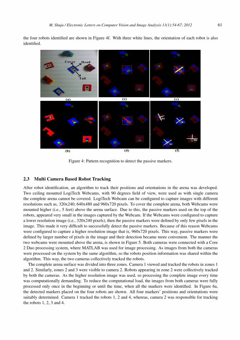
For robot and object localisation, a passive marker based approach was adopted. The markers developed inthis study utilised the colour information based on the fact that colours appearing in some certain pattern canbe very prominent in the environment. In Figure 4a, four markers conveying the unique ID information usingthree colours and following the same design template, are shown. One marker, with blue surrounding cover,was labeled to define the template. Cover, which defines the markers boundary, surrounds the head region fromthree directions and is open from one side of the tail region. Head region is the one which finds the tail regionin one direction and covers regions in three directions. And tail region is defined as the one which is open fromone direction, surrounded by a cover region from two directions, but finds the head and cover region togetherin one direction.
In Figure 4a, markers using all three colours are shown but with this approach, markers of the same colourscan also be designed. With this approach, not only 27 different robots can be identified, but at the same time italso conveys the orientation information. This approach provides an advantage over other approaches, such asthe one used in RoboCup [19], which uses the same number of colours, but can uniquely identify only 9 robots.To identify the markers, a colour blob detection based algorithm was developed. To perform image processing,MATLAB was selected as it provides a good platform for the proof of concept. For colour blobs detection,YUV format was used. The extracted colour blobs are shown in Figure 4b. Then segmentation of the resultingcolour blobs was performed. In other words, statistical information that is the centroid of each blob and thenumber of pixels, was extracted which was used to assign a fixed ID to each blob. This ID information helpedin determining the blobs connectivity when their search has been performed in a specified pattern.
The final stage was template matching and pattern recognition. The localisation system was given a priorknowledge about the identity of the different colours patterns appearing in the form of the designed template inthe given image. For example pattern using blue cover, red head and green tail blob is attached to robot 1. Thecomplete marker detection and identification process is as follows. After assigning a unique ID to all blobs,each blob was processed one by one and checked whether it was resulting from the head blob and followedthe designed pattern. An example, showing the step by step process is shown in Figure 4. When red blob wasconsidered as head region, then to make the process of template validation fast, a window was defined aroundthe selected blob (Figure 4c). Only those blobs which laid within this window were considered for templatevalidation. From the prior knowledge, the algorithm was aware that a green tail blob was in the possible setof patterns. In this case, it found the green blob in the search window as shown in Figure 4c. The algorithmthen determines the slope between the head and the tail blob and for this, it required the statistical informationthat was the centroid of the blobs. After obtaining the slope, it draws a search line (Figure 4d) along whichit searched for the closed cover blob in one direction (head direction) and open cover blob in the oppositedirection (tail direction). On finding the expected pattern, it draws another search line (shown in Figure 4e)perpendicular to the previous line. Along this search line, the algorithm searches for the cover blob on bothsides of head blob and use blob ID information to confirm cover blob connectivity. Following this approach
M. Shuja / Electronic Letters on Computer Vision and Image Analysis 11(1):54-67; 2012 61
the four robots identified are shown in Figure 4f. With three white lines, the orientation of each robot is alsoidentified.
Figure 4: Pattern recognition to detect the passive markers.
2.3 Multi Camera Based Robot Tracking
After robot identification, an algorithm to track their positions and orientations in the arena was developed.Two ceiling mounted LogiTech Webcams, with 90 degrees field of view, were used as with single camerathe complete arena cannot be covered. LogiTech Webcam can be configured to capture images with differentresolutions such as, 320x240, 640x480 and 960x720 pixels. To cover the complete arena, both Webcams weremounted higher (i.e., 5 feet) above the arena surface. Due to this, the passive markers used on the top of therobots, appeared very small in the images captured by the Webcam. If the Webcams were configured to capturea lower resolution image (i.e., 320x240 pixels), then the passive markers were defined by only few pixels in theimage. This made it very difficult to successfully detect the passive markers. Because of this reason Webcamswere configured to capture a higher resolution image that is, 960x720 pixels. This way, passive markers weredefined by larger number of pixels in the image and their detection became more convenient. The manner thetwo webcams were mounted above the arena, is shown in Figure 5. Both cameras were connected with a Core2 Duo processing system, where MATLAB was used for image processing. As images from both the cameraswere processed on the system by the same algorithm, so the robots position information was shared within thealgorithm. This way, the two cameras collectively tracked the robots.
The complete arena surface was divided into three zones. Camera 1 viewed and tracked the robots in zones 1and 2. Similarly, zones 2 and 3 were visible to camera 2. Robots appearing in zone 2 were collectively trackedby both the cameras. As the higher resolution image was used, so processing the complete image every timewas computationally demanding. To reduce the computational load, the images from both cameras were fullyprocessed only once in the beginning or until the time, when all the markers were identified. In Figure 6a,the detected markers placed on the four robots are shown. All four markers’ positions and orientations weresuitably determined. Camera 1 tracked the robots 1, 2 and 4, whereas, camera 2 was responsible for trackingthe robots 1, 2, 3 and 4.
62 M. Shuja / Electronic Letters on Computer Vision and Image Analysis 11(1):54-67; 2012
Figure 5: Ceiling mounted camera setup for robot tracking.
Figure 6: Collective tracking of robots from ceiling mounted cameras.
Once all the markers were identified, then the algorithm made a tracking database of the robots for bothcameras. After this, the algorithm made a search window around each robots’ last identified positions andexpected them to appear within that search window in the subsequent images. If the robots were not identifiedin that window then the algorithm increased the uncertainty about the robots’ positions and also increased thesearch window size. If a robot tracked by camera 1 moved from zone 1 to zone 2, then the algorithm not onlytracked it in camera 1 images, but it also added the robot’s ID in camera 2 tracking database. The algorithmdetermined the robot’s expected position in camera 2 image by solving the Homography between camera 1and 2. Similarly, the removal of robot’s ID from the tracking database was also important when the robot wasmoving from zone 2 to either zone 1 or zone 3. If the robot was moving from zone 2 to zone 1, then removalof robot’s ID was performed from camera 2 database. This case is shown in Figure 6b. Camera 1 was trackingrobots 1, 2 and 4 (Figure 6a) and camera 2 was tracking robots 1, 2, 3 and 4. In Figure 6b, robot 1 moves fromzone 2 to zone 1. The robot is no longer visible by camera 2, so its ID is removed from camera 2 trackingdatabase.
2.4 Robot Communication
For recognising and localising objects in the arena collectively by multiple robots, the robots needed to sharetheir knowledge with each other. For this purpose, a wireless communication medium (in infrastructure mode)was setup between all the robots. In the begining, SURF features of all the target objects were extracted andprovided to all the robots. Then all robots created database of the number of target objects which they were
M. Shuja / Electronic Letters on Computer Vision and Image Analysis 11(1):54-67; 2012 63
looking for. In the experiment, as the robots were not provided with any information about the location ofthe objects (because robots were expected to localise these objects). So all the robots tried to scan the wholescenario and recognised all the target objects on their way. Sometime, the robots revisited the search place,because they missed the target objects in the surrounding due to very small camera field of view (i.e., 60 degree)and slow recognition speed. For synchronising multiple robots, such that the target objects found by one robotneeded to be avoided by the other robots, a very simple knowledge update mechanism was implemented. Oncea robot detected and recognised an object of interest in the environment, then it localised that object with thehelp of robot localisation information provided by the ceiling mounted cameras. After localising the targetobject, robot removed this object from its search database. At the same time, the robot informed the otherrobots in the environment to remove the found object from their databases. Before proceeding to search forother objects in the environment, the robot waited for the acknowledgement from the other robots that they haveupdated their database successfully. Once all the robots removed the found objects from their search databasesthen next time, the robots did not try to match the features of the already found objects with the features of theobjects detected in their view. This speeded up the recognition process as the number of target objects reducedin the search database.
3 Results
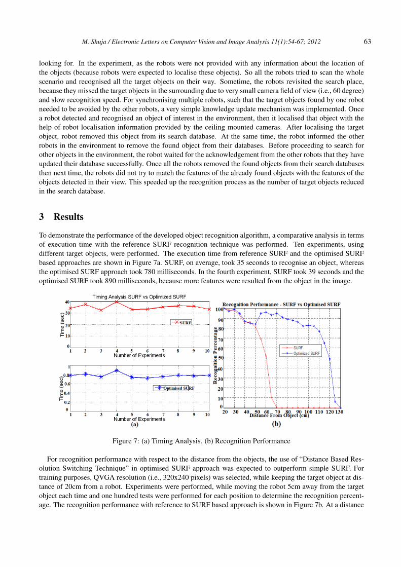
To demonstrate the performance of the developed object recognition algorithm, a comparative analysis in termsof execution time with the reference SURF recognition technique was performed. Ten experiments, usingdifferent target objects, were performed. The execution time from reference SURF and the optimised SURFbased approaches are shown in Figure 7a. SURF, on average, took 35 seconds to recognise an object, whereasthe optimised SURF approach took 780 milliseconds. In the fourth experiment, SURF took 39 seconds and theoptimised SURF took 890 milliseconds, because more features were resulted from the object in the image.
For recognition performance with respect to the distance from the objects, the use of “Distance Based Res-olution Switching Technique” in optimised SURF approach was expected to outperform simple SURF. Fortraining purposes, QVGA resolution (i.e., 320x240 pixels) was selected, while keeping the target object at dis-tance of 20cm from a robot. Experiments were performed, while moving the robot 5cm away from the targetobject each time and one hundred tests were performed for each position to determine the recognition percent-age. The recognition performance with reference to SURF based approach is shown in Figure 7b. At a distance
64 M. Shuja / Electronic Letters on Computer Vision and Image Analysis 11(1):54-67; 2012
of 20cm from the object, both approaches gave 100 percent correct identification. The performance of SURFbased approach degraded gradually as the robot moved away from the object and at a distance of 55cm, recog-nition droped below 70% because the object appeared very small in the QVGA image. From a 70cm distanceonward, recognition was not possible. In the case of Optimised SURF based approach, at a distance of 50cm,the use of “Resolution Switching Technique” determined that the robot was far from the object and processedthe object in the high resolution image which increased the number of SURF features and showed a suddenincrease in recognition performance. With the use of Resolution Switching Technique, the optimised SURFapproach was able to provide reliable performance (as shown in Figure 7b) even at the distance of 2.5 times thedistance at which SURF was able to perform the recognition.
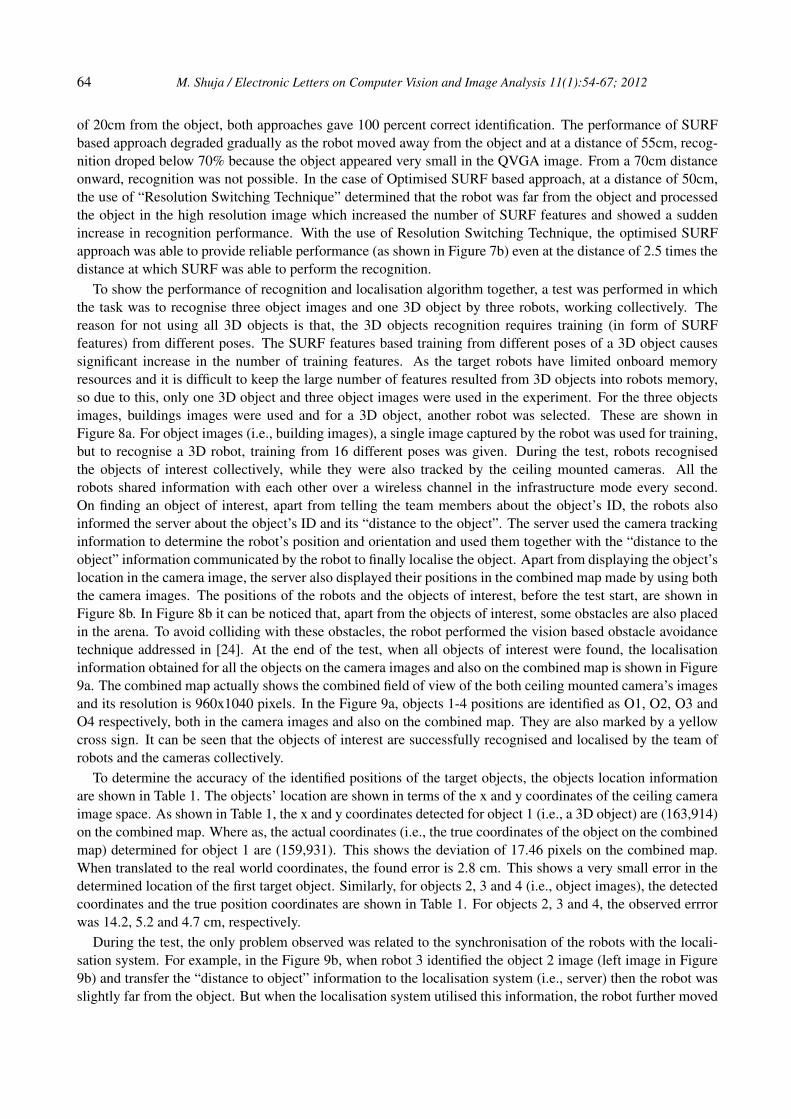
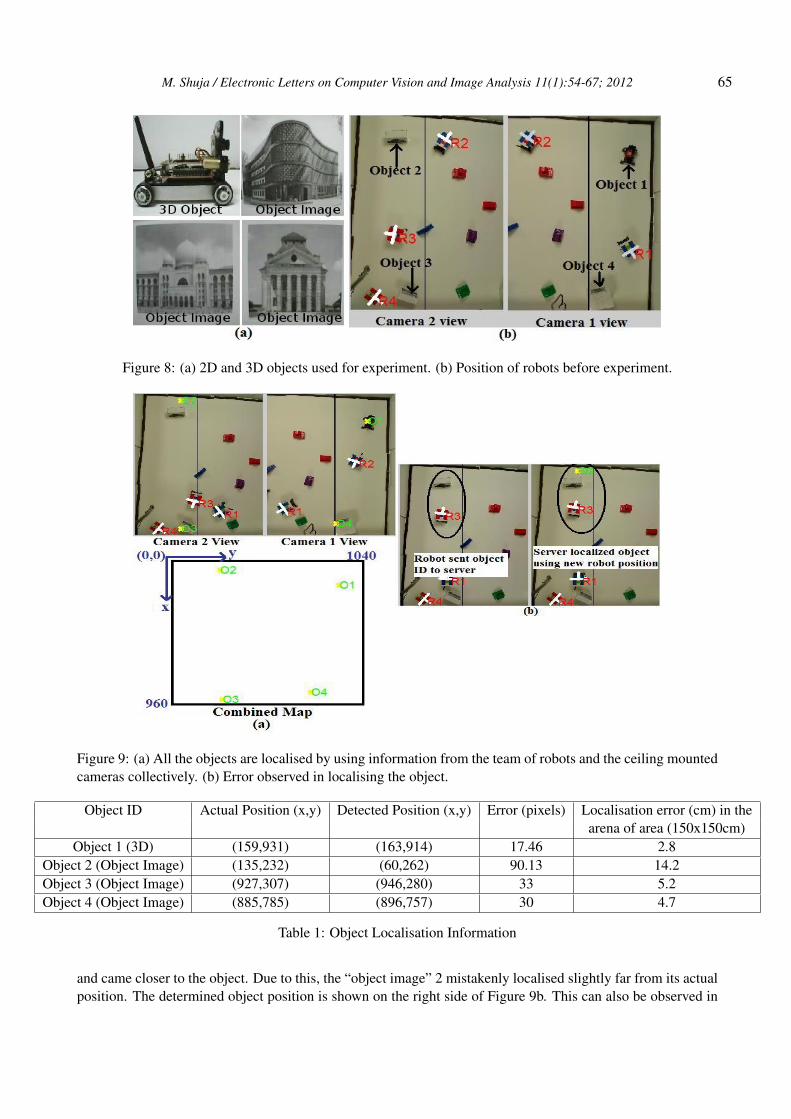
To show the performance of recognition and localisation algorithm together, a test was performed in whichthe task was to recognise three object images and one 3D object by three robots, working collectively. Thereason for not using all 3D objects is that, the 3D objects recognition requires training (in form of SURFfeatures) from different poses. The SURF features based training from different poses of a 3D object causessignificant increase in the number of training features. As the target robots have limited onboard memoryresources and it is difficult to keep the large number of features resulted from 3D objects into robots memory,so due to this, only one 3D object and three object images were used in the experiment. For the three objectsimages, buildings images were used and for a 3D object, another robot was selected. These are shown inFigure 8a. For object images (i.e., building images), a single image captured by the robot was used for training,but to recognise a 3D robot, training from 16 different poses was given. During the test, robots recognisedthe objects of interest collectively, while they were also tracked by the ceiling mounted cameras. All therobots shared information with each other over a wireless channel in the infrastructure mode every second.On finding an object of interest, apart from telling the team members about the object’s ID, the robots alsoinformed the server about the object’s ID and its “distance to the object”. The server used the camera trackinginformation to determine the robot’s position and orientation and used them together with the “distance to theobject” information communicated by the robot to finally localise the object. Apart from displaying the object’slocation in the camera image, the server also displayed their positions in the combined map made by using boththe camera images. The positions of the robots and the objects of interest, before the test start, are shown inFigure 8b. In Figure 8b it can be noticed that, apart from the objects of interest, some obstacles are also placedin the arena. To avoid colliding with these obstacles, the robot performed the vision based obstacle avoidancetechnique addressed in [24]. At the end of the test, when all objects of interest were found, the localisationinformation obtained for all the objects on the camera images and also on the combined map is shown in Figure9a. The combined map actually shows the combined field of view of the both ceiling mounted camera’s imagesand its resolution is 960x1040 pixels. In the Figure 9a, objects 1-4 positions are identified as O1, O2, O3 andO4 respectively, both in the camera images and also on the combined map. They are also marked by a yellowcross sign. It can be seen that the objects of interest are successfully recognised and localised by the team ofrobots and the cameras collectively.
To determine the accuracy of the identified positions of the target objects, the objects location informationare shown in Table 1. The objects’ location are shown in terms of the x and y coordinates of the ceiling cameraimage space. As shown in Table 1, the x and y coordinates detected for object 1 (i.e., a 3D object) are (163,914)on the combined map. Where as, the actual coordinates (i.e., the true coordinates of the object on the combinedmap) determined for object 1 are (159,931). This shows the deviation of 17.46 pixels on the combined map.When translated to the real world coordinates, the found error is 2.8 cm. This shows a very small error in thedetermined location of the first target object. Similarly, for objects 2, 3 and 4 (i.e., object images), the detectedcoordinates and the true position coordinates are shown in Table 1. For objects 2, 3 and 4, the observed errrorwas 14.2, 5.2 and 4.7 cm, respectively.
During the test, the only problem observed was related to the synchronisation of the robots with the locali-sation system. For example, in the Figure 9b, when robot 3 identified the object 2 image (left image in Figure9b) and transfer the “distance to object” information to the localisation system (i.e., server) then the robot wasslightly far from the object. But when the localisation system utilised this information, the robot further moved
M. Shuja / Electronic Letters on Computer Vision and Image Analysis 11(1):54-67; 2012 65
Figure 8: (a) 2D and 3D objects used for experiment. (b) Position of robots before experiment.
Figure 9: (a) All the objects are localised by using information from the team of robots and the ceiling mountedcameras collectively. (b) Error observed in localising the object.
Object ID Actual Position (x,y) Detected Position (x,y) Error (pixels) Localisation error (cm) in thearena of area (150x150cm)
and came closer to the object. Due to this, the “object image” 2 mistakenly localised slightly far from its actualposition. The determined object position is shown on the right side of Figure 9b. This can also be observed in
66 M. Shuja / Electronic Letters on Computer Vision and Image Analysis 11(1):54-67; 2012
Table 1, where the error in the detected position of “object image” 2 is 14.2 cm which is comparatively muchlarger than the error found in the position of object 1, 3 and 4. This problem can be easily fixed by adding anacknowledgment between the robot to the server communication such that the robot did not change its positionunless it was informed by the server that the “distance to object” information has been used.
4 Conclusion
In this study a collective effort, made by the team of small embedded robots together with two ceiling mountedcameras, to recognise and localise objects of interest in an environment, is presented. The manner a com-putationally expensive SURF feature based recognition approach can be made to run efficiently on embeddedrobotic platform is addressed. A new technique of “distance based resolution switching” is addressed which notonly helped the robots to recognise far lying objects, but the fact that it did not require a high resolution training(i.e., it helps keeping the training database size small), made the approach processor and memory efficient. Forlocalisation of the objects, as ceiling mounted cameras were far from the objects and could not identify theobjects in the environment alone, so the use of ceiling camera tracking information together with “distance toobject” information from the robots helped in localising the objects robustly. The research outcome addressedhere can be extended to a team of high performance robots equipped with GPS based localisation system andwhich can replace humans for performing a search operation in hazardeous environment (e.g., nuclear site) forlocalising the important places and updating the current view of the surrounding.
Acknowledgements
This research was funded by European Commission FP7/2007-2013 research project “REPLICATOR”.
References
[1] M. Mata, J. M. Armingol, A. de la Escalera, and M. A. Salichs, “Mobile robot navigation based on visuallandmarks recognition”, In Proc. 4th IFAC Symposium on Intelligent Autonomous Vehicles (IAV 01), BerlinSapporo, Japan, September 2001.
[2] J.A. Janet, W.J. Wiseman, R.D. Michelli, A.L. Walker and S.M. Scoggins, “Using Control Networks forDistributed Robotic Systems”, In Proceedings of the IEEE International Conference on Robotics Automa-tion, Detroit, Michigan. Vol.2, Pages: 1138-1143, May 1999.
[3] REPLICATOR, “Replicator-robotic evolutionary self-programming and self-assembling organisms”,In 7th Framework Programme Project No FP7-ICT-2007.2.1. European Communities., URL:http://symbrion.org/, last accessed on 20 Sep, 2012.
[4] A. Ramisa, S. Vasudevan, D. Scaramuzza, R. Lopez de Mantaras and R. Siegwart, “A Tale of Two ObjectRecognition Methods for Mobile Robots”, ICVS’08 Proceedings of the 6th international conference onComputer vision systems, Berlin, Publisher: Springer-Verlag, Vol.5008, Pages: 353-362, 2008.
[5] D.G. Lowe, “Distinctive image features from scale-invariant keypoints”, International Journal of ComputerVision, 2004, Vol.60, Issue 2, Pages: 91-110, Nov 2004.
[6] M. Tabuse and D. Nakai, “Mobile robot navigation using surf features”, ACS’10 Proceedings of the 10thWSEAS international conference on Applied computer science, Pages: 276-279, 2010.
[7] T. Goedeme, “Traffic sign recognition with constellations of visual words.”, International conference oninformatics in control, automation and robotics ICINCO, Pages: 222-227, 2008.
M. Shuja / Electronic Letters on Computer Vision and Image Analysis 11(1):54-67; 2012 67
[8] D. Asanza and B. Wirnitzer, “Improving feature based object recognition in service robotics by disparitymap based segmentation”, International Conference on Intelligent Robots and Systems (IROS), IEEE/RSJ.,Pages: 2716-2720, 2010.
[9] M. Cummins and P. Newman, “Fab-map: Appearance-based place recognition and mapping using a learnedvisual vocabulary model”, Proceedings of the 27th International Conference on Machine Learning (ICML-10), Haifa, Israel, Vol. 27, Issue 6, Pages: 647-665, 2008.
[10] G. Chrysanthakopoulos and G. Shani, “Augmenting appearance-based localisation and navigation usingbelief update”, Proceedings of AAMAS, Vol. 2, Pages: 559-566, 2010.
[11] M.M. Ullah, A. Pronobis, B. Caputo, J. Luo, P. Jensfelt and H.I. Christensen, “Towards robust placerecognition for robot localisation”, Int’l Conf on Robotics and Automation ICRA, Pages: 530-537, 2008.
[12] C. Ricardo, B. Rodrigues and S. Pellegrino, “An experimental evaluation of algorithms for aerial imagematching”, Eletronic Engineering and Computer Department. IWSSIP 2010 - 17th International Confer-ence on Systems, Signals and Image Processing, Pages: 416-419, 2010.
[13] L. Juan, O. Gwun, “A comparison of sift, pca-sift and surf”, International Journal of Image Processing(IJIP), Vol.3, Issue.4, Pages: 187-245, 2009.
[14] W. Burgard, D. Fox, K. Fishkin and M. Philipose, “Mapping and Localisation with RFID Technology”,In Proceedings of ICRA05, Vol. 1, Pages: 1015-1020, 2005.
[15] H. Lim and Y. S. Lee, “Real-time single camera SLAM using fiducial markers”, ICROS-SICE Interna-tional Joint Conf, Fukuoka International Congress Center, Japan, Pages: 177-182, August 18-21, 2009.
[16] B. Sohn, J. Lee, H. Chae and W. Yu, “Localisation system for mobile robot using wireless communicationwith IR landmark”, RoboComm ’07 Proceedings of the 1st international conference on Robot communica-tion and coordination, IEEE Press, Article.6, Pages: 61-66, 2007.
[17] P. Furgale, J. Anderson and J. Baltes, “Real-Time Vision-Based Pattern Tracking Without PredefinedColours”, In Proc of the Third International Conference on Computational Intelligence, Robotics and Au-tomation, Singapore, December 2005.
[18] A.C. Rice, A.R. Beresford and R.K. Harle, “Cantag: an open source software toolkit for designing anddeploying marker-based vision systems”, Fourth Annual IEEE International Conference on Pervasive Com-puting and Communications, Pages: 10-21, March 2006.
[19] M. Simon, S. Behnke and R. Rojas, “Robust Real Time Colour Tracking”, 4th International Workshop onRoboCup , Springer Vol.2019, Pages: 239-248, 2001.
[20] A. Kaehler and G. Bradski, “Computer vision with the opencv library”, Learning OpenCV, URL:http://opencv.willowgarage.com/, page 576, 2008.
[21] C. Evans, “Notes on the opensurf library.”, Technical Report CSTR-09-001, University of Bristol, URLhttp://www.cs.bris.ac.uk/Publications/Papers/2000970.pdf, January 2009.
[22] D. Katz, T. Lukasiak and R. Gentile, “Enhance processor performance in open-source applications.”,Analog Dialogue, Vol.39, February 2005.
[24] M.S. Ahmed, R. Saatchi, F. Caparrelli, “Vision based obstacle avoidance and odometery for swarms ofsmall size robots.”, In Proceedings of 2nd International Conference on Pervasive and Embedded Comput-ing and Communication Systems, Pages: 115-122, February 2012.


![Visual Localisation and Individual Identification of Holstein ...openaccess.thecvf.com/content_ICCV_2017_workshops/papers/...computer vision techniques in object detection [53, 22]](https://static.documents.pub/doc/80x56/603a2c6f2767bd69b56d8c80/visual-localisation-and-individual-identification-of-holstein-computer-vision.jpg)


