51


Vision Sensor Mounting instructions
Copyright (English)
No part of this document may be reproduced, published or stored in information retrieval systems or
data bases in any manner whatsoever, nor may illustrations, drawings and the layout be copied without
prior written permission from Festo Industriesensorik GmbH.
We accept no responsibility for printing errors and mistakes which occurred in drafting these document.
Subject to delivery and technical alterations.
First publication February 2011
Festo AG & Co. KG
D-73726 Esslingen
Internet: http://www.festo.com
E-Mail: [email protected]
Page 2 Vision Sensor SBSI/SBSC-EN, 8064181 - 1607b - 13/09/2016
Vision Sensor Mounting instructions
Open Source Licences
The SBS Vision Sensor software makes use of a couple of third party software packages that come with
various licenses. This section is meant to list all these packages and to give credit to those whos code
helped in the creation of the SBS Vision Sensor software.
For components that reference the GNU General Public License (GPL) or the GNU Lesser General
Public License (LGPL), please find these licenses and the written offer for source code in this software
installation in \FESTO\SBS Vision Sensor\Eula\OpenSourceLicenses.
The SBS Vision Sensor firmware makes use of Linux Version 2.6.33 (Website: www.kernel.org), which is
distributed under the GNU GPL version 2.
The SBS Vision Sensor firmware makes use of x-loader, an initial program loader for Embedded boards
based on OMAP processors (Website: http://arago-project.org/git/projects/?p=x-load-omap3.git;
a=summary) which is distributed under the GNU GPL version 2 or higher.
The SBS Vision Sensor firmware makes use of u-boot, an initial program loader for Embedded boards
based on OMAP processors (Website: http://arago-project.org/git/projects/?p=x-load-omap3.git;
a=summary) which is distributed under the GNU GPL version 2 or higher
The SBS Vision Sensor firmware makes use of spike Version 0.2,a SPI-driver (Website:
https://github.com/scottellis/spike/blob/master/spike.c ), which is distributed under the GNU GPL version
2 or higher.
The SBS Vision Sensor firmware makes use of Busy-Box Version 1.18.1 ( Website:
http://www.busybox.net/ ), which is distributed under the GNU GPL version 2 or higher
The SBS Vision Sensor firmware makes use of vsftpd Version 2.0.3 ( Website:
https://security.appspot.com/vsftpd.html ), which is distributed under the GNU GPL version 2 or higher.
The SBS Vision Sensor firmware makes use of mtd-utils Version 1.5.0 ( Website: http://www.linux-
mtd.infradead.org/doc/general.html ), which is distributed under the GNU GPL version 2 or higher.
The SBS Vision Sensor firmware makes use of Boa Webserver Version 0.94.13 ( Website:
http://www.boa.org/ ), which is distributed under the GNU GPL version 2 or higher.
The SBS Vision Sensor firmware makes use of Procps Version 3.2.8 ( Website
http://procps.sourceforge.net/download.html), which is distributed under the GNU GPL version 2 or
higher and GNU LGPL version 2.1 or higher.
The SBS Vision Sensor firmware makes use of GnuPG Version 1.4.10 ( Website: https://www.gnupg.org/
), which is distributed under the GNU GPL version 3 or higher.
The SBS Vision Sensor firmware makes use of glibc, which is distributed under GNU LGPL version 2.1 or
higher.
The SBS Vision Sensor firmware makes use of Dropbear - a SSH2 server Version 2012.55 ( Website:
https://matt.ucc.asn.au/ dropbear/dropbear.html ). The Dropbear SSH2 server is distributed under the
terms of the Dropbear License which is a MIT/X Consortium style open source license. Please find this
license in this software installation in \FESTO\SBS \Eula\OpenSourceLicenses
Vision Sensor Configuration Studio software is based in part on the work of the Qwt project
(http://qwt.sf.net).
Vision Sensor SBSI/SBSC-EN, 8064181 - 1607b - 13/09/2016 Page 3

Vision Sensor Mounting instructions
Table of Contents
1 General Information and Safety 6
1.1 Safety notes 6
1.2 Components supplied 6
1.3 Requirements for use 6
2 Intended Use 7
2.1 Field of application 7
2.2 Functions overview 8
2.2.1 Functions overview: Color sensor, Universal 9
2.3 Sensor types 11
2.3.1 Object detection 11
2.3.2 Code Reader 12
2.3.3 Color Sensor 13
2.3.4 Universal 14
2.4 Field of view / Depth of view 15
4 Installation 20
4.1 Mechanical Installation 20
4.1.1 Arrangement for dark-field illumination 20
4.1.2 Arrangement for bright-field illumination 21
4.1.3 Alignment for a vertical illumination 22
4.1.4 Assembly SBS - Mounting bracket MK 45 23
4.2 Electrical installation 23
4.2.1 Connection possibilities 24
4.2.1.1 LED Display 24
4.2.1.2 Focussing screw 25
4.2.1.3 24 V DC Connection 25
4.2.1.4 LAN Connection 25
4.2.1.5 Data Connection 25
4.2.2 Plug connections 26
4.2.2.1 PIN assignment, connection 24 V DC 26
4.2.2.2 PIN assignment, connection LAN 26
4.2.2.3 PIN assignment DATA *A) 27
4.2.2.4 Exemplary connection plan and software settings for the following setup: 27
4.2.2.5 Electrical connection supply voltage and shield 28
4.2.2.6 Electrical connection PNP / NPN 28
4.3 Network settings, Short reference 29
4.3.1 Basic settings for PC and SBS Vision Sensor 29
4.3.2 Direct Connection - Setting the IP Address of the PC 30
4.3.3 Network Connection - Setting the IP address of the SBS Vision Sensor 31
5 SBS – Operating- and configuration software 33
5.1 SBS – Operating- and configuration software - Overview 33
5.1.1 Structure of PC software 33
5.1.2 Context help 33
5.2 SBS – Operating- and configuration software – Short introduction 34
5.2.1 SBS, Short introduction, Starting the software 34
5.2.2 Vision Sensor Device Manager: Open sensors or sensor simulation / Passwords 34
5.2.3 Passwords 36
Page 4 Vision Sensor SBSI/SBSC-EN, 8064181 - 1607b - 13/09/2016

Vision Sensor Mounting instructions
5.2.4 Password levels: 36
5.3 Vision Sensor Configuration Studio: Setting sensor, Job 38
5.3.1 Job Setup 39
5.3.2 Alignment settings 40
5.3.3 Detector settings 41
5.3.4 Output, I/O and data output 42
5.3.5 Result 44
5.3.6 Start sensor 45
5.4 Vision Sensor Visualisation Studio, display images and results 46
6 Technical Data 47
7 Type key 50
Vision Sensor SBSI/SBSC-EN, 8064181 - 1607b - 13/09/2016 Page 5

Vision Sensor Mounting instructions
1 General Information and Safety
1.1 Safety notes
Before starting the SBS Vision Sensor, read these instructions carefully, ensure that you have understood
them and comply with them at all times.
The SBS Vision Sensor should only be connected by a qualified electrician.
Do not tamper with or make alterations on the unit!
The SBS Vision Sensor is not a safety-critical component and its use is prohibited under conditions where
the safety of persons may depend on its function.
The IP address set for the SBS Vision Sensor should be marked on the enclosed label. After installation,
stick the label on the sensor in a clearly visible position.
The IP address of the SBS Vision Sensor must be used once only in any network.
For Use with any Listed (CYJV) cable assembly.
1.2 Components supplied
l SBS Vision Sensor including integrated illumination (or as version with C-Mount lens without
illumination)
l CD-ROM with Computer software and Operating instructions
l Data sheet, mounting clamp, allen key, screwdriver and protective cap for Ethernet plug.
1.3 Requirements for use
Configuration of the SBS Vision Sensor requires a standard PC/Notebook (at least Pentium 4, 1GHz and
1 GB RAM, with Microsoft Windows 7 or Windows 10) with network connection or a network with
TCP-IP protocol. We recommend a Pentium 4 Dual Core > 2GHz and 2GB RAM, for Windows 7 or
Windows 10. We recommend a screen resolution of min. 1024 x 768 pixels. A basic knowledge of
computers is also required. The SBS Vision Sensor is supplied with the IP address 192.168.100.100 and a
subnet mask 255.255.255.0. The SBS Vision Sensor is operated independently of a PC or PLC. A
PC/notebook is only necessary for configuration of the SBS Vision Sensor.
Attention must be paid to sufficient and constant object illumination to ensure reproducible results and
avoid malfunction.
Reflections or varying incident light may affect detection results. If necessary, use an external light source
and/or light-screening / shrouding devices to exclude incident light
Page 6 Vision Sensor SBSI/SBSC-EN, 8064181 - 1607b - 13/09/2016

Vision Sensor Mounting instructions
2 Intended Use
2.1 Field of application
The SBS Vision Sensor is an optical sensor and uses several evaluation methods according to the version:
pattern recognition, contrast detection, grey level, contour detection, barcode or Data Matrix code
reading, Optical character reading as well as wafer detection. The product is designed for industrial use
only. In residential areas possibly additional measures for noise suppression must be done.
Object:
The SBS Vision Sensor precisely detects faulty parts, parts in the wrong place, at the wrong angle or in
the wrong order or a combination of all of these. Several detectors are available for inspection tasks and
interpretation: e.g. pattern matching, contour detection, brightness, grey level, contrast detection, caliper
or BLOB. The advanced version of the SBS Vision Sensor also offers alignment: it is thus now also
possible to reliably detect those features which do not appear with repeated accuracy in the taught
position. All interpretation is carried out relative to the actual position and angle of the part without
having to define an independent characteristic for each possible position. This high capacity tool also
enables you to solve demanding pick and place applications.
The advanced version offers also the calibration in world coordinates for measurement- and robot
applications.
Code Reader:
Identification of products, components or packaging from printed or directly marked – punched or laser-
etched – codes is common practice in many sectors of industry today. The Vision Code Reader from
Festo immediately detects which part is in front of it: it can easily read numerous types of barcodes as
well as printed and directly marked data matrix codes according to ECC 200 standard and read characters
directly via Optical Character Reading (OCR), and this on any base (metal, plastic, paper, glass). The
sensor can even routinely decipher askew or warped codes or codes on convex, reflective or transparent
surfaces. The Vision Code Reader assesses the quality of your printed or directly marked data matrix
codes using standardised ISO and AIM quality parameters. This enables you to introduce early
correctional measures and thus avoid rejects due to illegible codes.
Color:
The SBS Color offers powerful object detection in combination with color detection. This leads to an
increased stability in several object detection applications as well as the possibility to sort colored parts
which would have a similar look in grey image. Beside this even active objects (like e.g. lighting LED´s) or
"non colors" like black and white can be detected.
Universal
In the SBS Universal all functions of SBS Object, Code Reader and Color are available in combination in
one device. The Professional version offers also the Mutishot function to detect smallest surface defects.
The SBS Vision Sensor range is an economic alternative to conventional image processing systems.
Vision Sensor SBSI/SBSC-EN, 8064181 - 1607b - 13/09/2016 Page 7

Vision Sensor Mounting instructions
2.2 Functions overview
Characteristics: Object / Code Reader / Solar
FunctionObject
Std.
Object
Adv.
Code Reader
Std.
Code Reader
Adv.
Frames per second 50 50 50 50
Number of Jobs 8 255 8 255
Alignment Contour only X X
Calibration in world coordinates X
Number of detectors 32 255 2 255
- Pattern matching
(X-, Y- translation)X X X
- Contour matching
(X-, Y- translation and rotation)X X
- Grey level X X X
- Contrast X X X
- Brightness X X X
- Caliper X
- BLOB X
- Data code X X
- Barcode X X
- OCR
4 digital outputs, 2 inputs,
PNP or NPNX X X X
Free definable digital In- / Outputs, PNP or NPN 2 4 2 4
Free shape of ROI contour only X X
Timeout, specified time response X X X X
Variable resolutions X X X X
Illumination quadrant controlled X X X X
Image recorder X X X X
Page 8 Vision Sensor SBSI/SBSC-EN, 8064181 - 1607b - 13/09/2016

Vision Sensor Mounting instructions
FunctionObject
Std.
Object
Adv.
Code Reader
Std.
Code Reader
Adv.
Encoder input X X
Ethernet interface X X X X
PROFINET X X X X
RS422 / RS232 interface X X X
EtherNet/IP interface X X X X
Sensor monitoring by Viewer, Job-Upload X X X X
Sensor monitoring by
SBSxWebViewer(Webviewer)X X X X
R3B integrated 6 / 12 X / X X / X X / X X / X
R2B integrated 12 mm X X
Version with C-Mount X X
2.2.1 Functions overview: Color sensor, Universal
Characteristics SBS Color, Universal
FunctionColor
Standard
Color
Advanced
Monochrome
Universal
Advanced
Frames per second 40 40 40
Number of Jobs 8 255 255
Alignment Contour only X X
Calibration in world coordinates X
Number of detectors 32 255 255
- Pattern matching
(X-, Y- translation)X X
- Contour matching
(X-, Y- translation and rotation)X X
- Grey level X X
- Contrast X X X
- Brightness X X
- Caliper X X
- BLOB X X
Vision Sensor SBSI/SBSC-EN, 8064181 - 1607b - 13/09/2016 Page 9

Vision Sensor Mounting instructions
FunctionColor
Standard
Color
Advanced
Monochrome
Universal
Advanced
- Data code X
- Barcode X
- OCR X
- Color value X
- Color area X X
- Color List X
4 digital outputs, 2 inputs,
PNP or NPNX X X
Free definable digital In- / Outputs, PNP or NPN 2 4 4
Free shape of ROI Contour only X X
Timeout, specified time response X X X
Variable resolutions X X X
Illumination quadrant controlled X X X
Image recorder X X X
Encoder input X X
Ethernet interface X X X
PROFINET X X X
RS422 / RS232 interface X X
EtherNet/IP interface X X X
Sensor monitoring by Viewer, Job-Upload X X X
Sensor monitoring by SBSxWebViewer (Webviewer) X X X
R3B integrated 6 / 12 X / X X / X
R2B integrated 12 mm X
Version with C-Mount X X
Page 10 Vision Sensor SBSI/SBSC-EN, 8064181 - 1607b - 13/09/2016

Vision Sensor Mounting instructions
2.3 Sensor types
2.3.1 Object detection
Part no. Type OpticsDepth of
focus
Internal
illumination
min.
operating
distance /
mm *1
min. Field of
view mm x
mm
R3B Advanced White
8058724 SBSI-Q-AF-R3B-F6-W 6 Normal White 6 5 x 4
8058725 SBSI-Q-AF-R3B-F12-W 12 Normal White 30 8 x 6
R3B Advanced IR
8058726SBSI-Q-AF-R3B-F6-NR*3
6 Normal InfraRed 6 5 x 4
8058727SBSI-Q-AF-R3B-F12-NR*3
12 Normal InfraRed 30 8 x 6
R3B Advanced C-Mount
8058728 SBSC-Q-AF-R3B *2,3 C-Mount Externallens
dependant
lens
dependant
R3B Standard White
2942261 SBSI-Q-R3B-F6-W 6 Normal White 6 5 x 4
2942262 SBSI-Q-R3B-F12-W 12 Normal White 30 8 x 6
R3B Standard IR
2942265 SBSI-Q-R3B-F6-NR *3 6 Normal InfraRed 6 5 x 4
2942266 SBSI-Q-R3B-F12-NR *3 12 Normal InfraRed 30 8 x 6
R2B Advanced White
8058730 SBSI-Q-AF-R2B-F12-W 12 Normal White 30 16 x 13
R2B Advanced C-Mount
8058729 SBSC-Q-AF-R2B*2,3 C-Mount Externallens
dependant
lens
dependant
*1 For longer operating distances (from approx. 200 mm) external illumination may be necessary.
*2 When the C-Mount version of SBS is in use, a C-Mount lens with a 5 mm intermediate ring (delivered
separately) or a C-Mount protective case is required.
*3 External IR illumination is only possible with IR sensors or C-Mount sensors.
Vision Sensor SBSI/SBSC-EN, 8064181 - 1607b - 13/09/2016 Page 11

Vision Sensor Mounting instructions
2.3.2 Code Reader
Part no. Type OpticsDepth of
focus
Internal
illumination
min. operating
distance / mm*1
min. Field of
view mm x
mm
R3B Advanced White
8058715 SBSI-B-AF-R3B-F6-W 6 Normal White 6 5 x 4
8058716 SBSI-B-AF-R3B-F12-W 12 Normal White 30 8 x 6
R3B Advanced Red
8058717 SBSI-B-AF-R3B-F6-R 6 Normal Red 6 5 x 4
8058718 SBSI-B-AF-R3B-F12-R 12 Normal Red 30 8 x 6
R3B Advanced IR
8058719 SBSI-B-AF-R3B-F6-NR *3 6 Normal InfraRed 6 5 x 4
8058720SBSI-B-AF-R3B-F12-NR*3
12 Normal InfraRed 30 8 x 6
R3B Advanced C-Mount
8058721 SBSC-B-AF-R3B *2,3 C-
MountExternal
lens
dependant
lens
dependant
R3B Standard White
2930232 SBSI-B-R3B-F6-W 6 Normal White 6 5 x 4
2930233 SBSI-B-R3B-F12-W 12 Normal White 30 8 x 6
2930242 SBSI-B-R3B-F6-W-D 25 Normal White 140 18 x 14
2930243 SBSI-B-R3B-F12-W-D 6 Enhanced White 6 5 x 4
R3B Standard Red
2930234 SBSI-B-R3B-F6-R 6 Normal Red 6 5 x 4
2930235 SBSI-B-R3B-F12-R 12 Normal Red 30 8 x 6
2930236 SBSI-B-R3B-F6-R-D 25 Normal Red 140 18 x 14
2930237 SBSI-B-R3B-F12-R-D 6 Enhanced Red 6 5 x 4
2930234 SBSI-B-R3B-F6-R 12 Enhanced Red 30 8 x 6
R3B Standard IR
2930238 SBSI-B-R3B-F6-NR *3 6 Normal InfraRed 6 5 x 4
2930239 SBSI-B-R3B-F12-NR *3 12 Normal InfraRed 30 8 x 6
2930240 SBSI-B-R3B-F6-NR-D *3 6 Enhanced InfraRed 6 5 x 4
Page 12 Vision Sensor SBSI/SBSC-EN, 8064181 - 1607b - 13/09/2016

Vision Sensor Mounting instructions
Part no. Type OpticsDepth of
focus
Internal
illumination
min. operating
distance / mm*1
min. Field of
view mm x
mm
2930241 SBSI-B-R3B-F12-NR-D *3 12 Enhanced InfraRed 30 8 x 6
R2B Advanced Red
8058723 SBSI-B-AF-R2B-F12-R 12 Normal Red 30 16 x 13
R2B Advanced C-Mount
8058722 SBSC-B-AF-R2B*2,3 C-
MountExternal
lens
dependant
lens
dependant
*1 For longer operating distances (from approx. 200 mm) external illumination may be necessary.
*2 When the C-Mount version of SBS is in use, a C-Mount lens with a 5 mm intermediate ring (delivered
separately) or a C-Mount protective case is required.
*3 External IR illumination is only possible with IR sensors or C-Mount sensors.
2.3.3 Color Sensor
Part no. Type OpticsDepth
of focus
Internal
illumination
min. operating
distance / mm *1
min. Field of
view mm x
mm
R3B Advanced White
8058733 SBSI-F-AF-R3C-F6-W 6 Normal White 6 5 x 4
8058734 SBSI-F-AF-R3C-F12-W 12 Normal White 30 8 x 6
R3B Advanced C-Mount
8058735 SBSC-F-AF-R3C *2 C-
MountExternal
lens
dependant
lens
dependant
R3B Standard White
8058731 SBSI-F-R3C-F6-W 6 Normal White 6 5 x 4
8058732 SBSI-F-R3C-F12-W 12 Normal White 30 8 x 6
*1 For longer operating distances (from approx. 200 mm) external illumination may be necessary.
*2 When the C-Mount version of SBS is in use, a C-Mount lens with a 5 mm intermediate ring (delivered
separately) or a C-Mount protective case is required.
Vision Sensor SBSI/SBSC-EN, 8064181 - 1607b - 13/09/2016 Page 13

Vision Sensor Mounting instructions
2.3.4 Universal
Part no. Type OpticsDepth of
focus
Internal
illumination
min.
operating
distance /
mm *1
min. Field of
view mm x
mm
R2B Universal C-Mount
8058736 SBSC-U-AF-R2B*2,3 C-Mount Externallens
dependant
lens
dependant
R3B Universal C-Mount
8058737 SBSC-U-AF-R3B*2,3 C-Mount Externobjektiv-
abhängig
objektiv-
abhängig
*1 For longer operating distances (from approx. 200 mm) external illumination may be necessary.
*2 When the C-Mount version of SBS is in use, a C-Mount lens with a 5 mm intermediate ring (delivered
separately) or a C-Mount protective case is required.
*3 External IR illumination is only possible with IR sensors or C-Mount sensors.
Page 14 Vision Sensor SBSI/SBSC-EN, 8064181 - 1607b - 13/09/2016

Vision Sensor Mounting instructions
2.4 Field of view / Depth of view
Field of view R3B 6mm lens, internal
Fig. 1: Field of view R3B 6mm lens, internal
Field of view R3B 12mm lens, internal
Fig. 2: Field of view R3B 12mm lens, internal
Field of view R2B 12mm lens, internal
Vision Sensor SBSI/SBSC-EN, 8064181 - 1607b - 13/09/2016 Page 15

Vision Sensor Mounting instructions
Fig. 3: Field of view R2B 12mm lens, internal
Page 16 Vision Sensor SBSI/SBSC-EN, 8064181 - 1607b - 13/09/2016

Vision Sensor Mounting instructions
Depth of view R3B 6mm lens internal, normal
Fig. 4: Depth of view R3B 6mm lens internal, normal
Depth of view R3B 6mm lens internal, enhanced
Fig. 5: Depth of view R3B 6mm lens internal, enhanced
Vision Sensor SBSI/SBSC-EN, 8064181 - 1607b - 13/09/2016 Page 17

Vision Sensor Mounting instructions
Depth of view R3B 12mm lens internal, normal
Fig. 6: Depth of view R3B 12mm lens internal, normal
Depth of view R3B 12mm lens internal, enhanced
Fig. 7: Depth of view R3B 12mm lens internal, enhanced
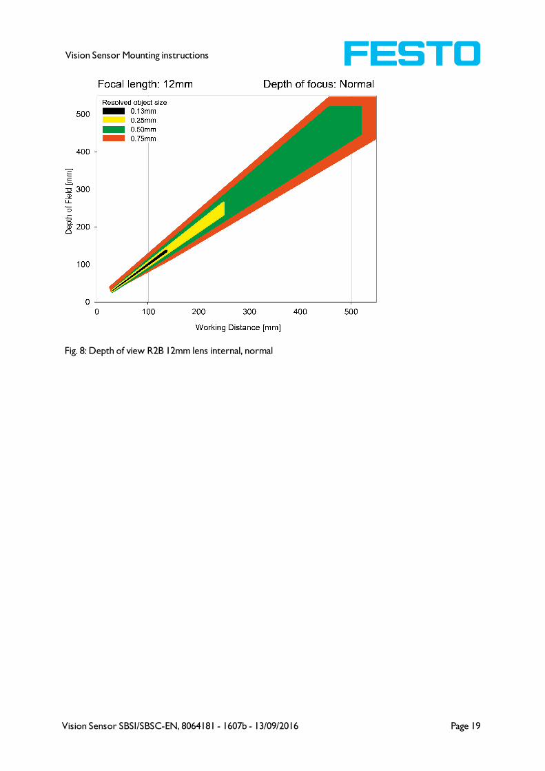
Depth of view R2B 12mm lens internal, normal
Page 18 Vision Sensor SBSI/SBSC-EN, 8064181 - 1607b - 13/09/2016
Vision Sensor Mounting instructions
Fig. 8: Depth of view R2B 12mm lens internal, normal
Vision Sensor SBSI/SBSC-EN, 8064181 - 1607b - 13/09/2016 Page 19

Vision Sensor Mounting instructions
4 Installation
4.1 Mechanical Installation
To ensure maximum accuracy of detection, the SBS Vision Sensor should be protected from vibration.
Secure the supply and I/O cables with cable binders to prevent crushing or slipping.
Select a position for the SBS Vision Sensor in which interfering factors such as slight differences in the
position of the object or variations in illumination have little or no effect.
Screw the SBS Vision Sensor onto the mounting clamp (supplied with the unit) and then onto a suitable
object. Use only the mounting clamp MK 45 (no. 543-11000) or the mounting hinge MG2A (no.543-
11023).
4.1.1 Arrangement for dark-field illumination
For the prevention of direct reflections and accentuation of edges etc.
Fig. 9: Arrangement for dark-field illumination
Page 20 Vision Sensor SBSI/SBSC-EN, 8064181 - 1607b - 13/09/2016

Vision Sensor Mounting instructions
4.1.2 Arrangement for bright-field illumination
For transmitted light/measuring tasks or for the accentuation of highly-reflective objects
Fig. 10: Arrangement for bright-field illumination
Observe the object clearance given in the table Field of View / Working Distance.
To avoid interfering reflection from the detection object, align the SBS Vision Sensor at an angle of
approx. 10°- 15° with reference to the optical axis.
Fine adjustment
Important: Fine adjustment of the SBS Vision Sensor should not be carried out until after electrical
connection and start-up (PC software installation).
Vision Sensor SBSI/SBSC-EN, 8064181 - 1607b - 13/09/2016 Page 21

Vision Sensor Mounting instructions
4.1.3 Alignment for a vertical illumination
In order to assure the absolutely vertical alignment of the SBS to the object surface, put a piece of
reflective foil or a mirror on top of the object and start the SBS operating software. For an image that is
continually updated, select trigger mode „free run ? “ and image update: „continuous ?“. Then align the
sensor to the reflective surface / the mirror as vertical as possible until the integrated illumination LEDs
are directly dazzling in the image of the user interface (Arrangement for bright-field illumination (Page
21)).
Fig. 11: Alignment for a vertical illumination
Page 22 Vision Sensor SBSI/SBSC-EN, 8064181 - 1607b - 13/09/2016

Vision Sensor Mounting instructions
4.1.4 Assembly SBS - Mounting bracket MK 45
Fig. 12: Assembly SBS - Mounting bracket MK 45
For fixing the SBS on a fixing system / machine housing, slide the provided dovetail mounting bracket
MK45 on the dovetail guide at the bottom side of the SBS and fix it at the desired position with the
hexagon socket in the cross hole of the mounting bracket. Then further Festo mounting accessories may
be attached to the mounting bracket or any other attachments may be fixed by using the tapped holes in
the MK45.
4.2 Electrical installation
The electrical installation of the SBS Vision Sensor must be carried out by a qualified person. When
installing the SBS Vision Sensor, disconnect all electrical components from the power supply. When the
unit is being used in a network, ensure that the network address (IP address) of the SBS Vision Sensor
set by the manufacturer at 192.168.100.100 is free and is not in use for any other unit connected to the
system.
If necessary, re-set the IP address of the SBS Vision Sensor as described in the section „Network
settings“.
When the SBS Vision Sensor is in use, the protective caps supplied must be pushed onto the M12
sockets (data and LAN) which are not in use. For error free operation the length of the connecting cables
must not be longer than 30 m.Failure to do this may cause malfunction.
Vision Sensor SBSI/SBSC-EN, 8064181 - 1607b - 13/09/2016 Page 23
Vision Sensor Mounting instructions
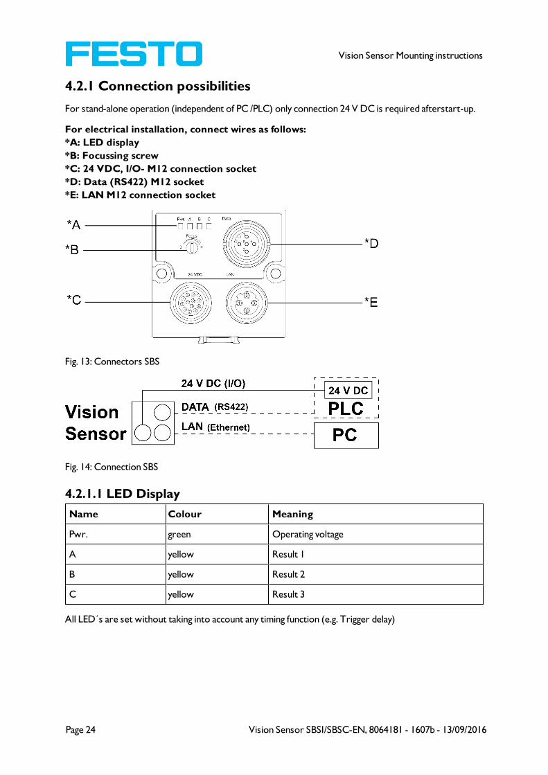
4.2.1 Connection possibilities
For stand-alone operation (independent of PC /PLC) only connection 24 V DC is required afterstart-up.
For electrical installation, connect wires as follows:
*A: LED display
*B: Focussing screw
*C: 24 VDC, I/O- M12 connection socket
*D: Data (RS422) M12 socket
*E: LAN M12 connection socket
Fig. 13: Connectors SBS
Fig. 14: Connection SBS
4.2.1.1 LED Display
Name Colour Meaning
Pwr. green Operating voltage
A yellow Result 1
B yellow Result 2
C yellow Result 3
All LED´s are set without taking into account any timing function (e.g. Trigger delay)
Page 24 Vision Sensor SBSI/SBSC-EN, 8064181 - 1607b - 13/09/2016

Vision Sensor Mounting instructions
4.2.1.2 Focussing screw
Focussing screw to adjust focus.
Focus: Clockwise = higher distance
Counter Clockwise = lower distance
4.2.1.3 24 V DC Connection
M12 Connection socket for 24 V DC voltage supply and digital I/O.
For the exact plug connection see PIN assignment, connection 24 V DC
4.2.1.4 LAN Connection
M12 Connection socket for Ethernet connection.
For the exact plug connection see PIN assignment, connection LAN .
Use only the correct network cables.
4.2.1.4.1 Direct connection of the SBS Vision Sensor to a PC
(recommended)
Fig. 15: Direct connection SBS <> PC
4.2.1.4.2 Connection of the SBS Vision Sensor to a PC via a network:
Fig. 16: Connection via a network
4.2.1.5 Data Connection
M12 Connection socket for DATA serial interface, RS422 / RS232.
s. PIN assignment DATA *A) (Page 27)
Vision Sensor SBSI/SBSC-EN, 8064181 - 1607b - 13/09/2016 Page 25

Vision Sensor Mounting instructions
4.2.2 Plug connections
All pin assignments and signals are referring to the view from the sensor.
4.2.2.1 PIN assignment, connection 24 V DC
PIN Colour Use
1 BN + Ub (24V DC)
2 BU GND
3 WH IN (external trigger)
4 GN READY *1
5 *2, *5 PK IN/OUT (advanced: encoder B+)
6 *2, *5 YE IN/OUT
7 *2 BK IN/OUT, LED B*4
8 *2 GY IN/OUT, LED C*4
9 RD OUT (external illumination)
10 VT IN (advanced: encoder A+)
11 GYPK VALID *3
12 RDBU OUT (ejector, max. 100mA), LED A*4
*1 Ready: Ready for next ext. trigger.
*2 Switchable input- output
*3 VALID: shows available results
*4 All LED´s are set without taking into account any timing function (e.g. Trigger delay)
*5 Not available with all Standard types
For shielded cables use shield, extensively connected.
4.2.2.2 PIN assignment, connection LAN
(M12) 4 pin Signal
1 TxD+
2 RxD+
3 TxD-
4 RxD-
Page 26 Vision Sensor SBSI/SBSC-EN, 8064181 - 1607b - 13/09/2016

Vision Sensor Mounting instructions
4.2.2.3 PIN assignment DATA *A)
PIN ColourUse
RS422
use
RS232
1 brown RxD+ Rx
2 white RxD- NC
3 blue TxD+ NC
4 black TxD- Tx
5 grey GND GND
*A) Not with Object- , Color-;Solar- Standard version
For shielded cables use shield.
4.2.2.4 Exemplary connection plan and software settings for the
following setup:
l Power supply
l Trigger
l 1x digital output
l Encoder
l Ethernet to PC or PLC
Fig. 17: Exemplary connection plan
Vision Sensor SBSI/SBSC-EN, 8064181 - 1607b - 13/09/2016 Page 27

Vision Sensor Mounting instructions
4.2.2.5 Electrical connection supply voltage and shield
Fig. 18: Electrical connection, supply voltage 24VDC in cabinet with shield
4.2.2.6 Electrical connection PNP / NPN
Fig. 19: Connection example SBS in PNP mode. In-/outputs switch to +24V
Fig. 20: Connection example SBS in NPN mode
As the inputs refer to ground, an additional pull-up resistor may be required in order to increase the input
voltage to 24V when unswitched. The outputs switch to ground.
Page 28 Vision Sensor SBSI/SBSC-EN, 8064181 - 1607b - 13/09/2016
Vision Sensor Mounting instructions
4.3 Network settings, Short reference
The following instructions indicate how to change the network configuration of the PC and the SBS
Vision Sensor. If incorrect settings are used, the network connections in the computer may be lost. To be
on the safe side, note the former settings for later use if required.
Following this procedure, it may be necessary to re-start the system. In order to determine which IP
addresses are allowed in your network or locally in your PC, and to carry out the necessary settings on
your PC, contact the system administrator beforehand.
The illustrations, dialogues and menus originate from the operating system Microsoft
WindowsXPTM. The illustrations are similar in other operating systems.
4.3.1 Basic settings for PC and SBS Vision Sensor
To configure the SBS Vision Sensor with a PC it is essential that a network board and the TCP/IP LAN-
connection is installed on the PC (This also applies when the PC is not connected to a network). The SBS
supports the automatic recognition of the Ethernet transmission rate, but 100 MBit at the most.
The internet protocol IPv4 must be activated.
There are two alternatives to configure and parameterize the SBS Vision Sensor.
See also chap. Network connection
1. Direct Connection
2. Network Connection
Vision Sensor SBSI/SBSC-EN, 8064181 - 1607b - 13/09/2016 Page 29

Vision Sensor Mounting instructions
4.3.2 Direct Connection - Setting the IP Address of the PC
To connect the SBS Vision Sensor to a PC via Ethernet the IP addresses of both devices have to
correspond. The default IP of the SBS is 192.168.100.100 with Subnet mask = 255.255.255.0. To establish
a direct connection, the PC must be set to a corresponding, fixed IP address like follows.
1. Click on Start / Control Panel / Network Connection / LAN Connection / Properties, the window
"Local Area Connection Properties" opens.
2. In the list „This connection requires following elements“ select the option „Internet Protocol
(TCP/IP)“ and then click the button „Properties“.
3. In the following window (see fig. 7) set the desired IP address of the PC and the sub-network data.
4. Confirm entries with OK
Example:
The SBS Vision Sensor is pre-set to IP address 192.168.100.100 and subnet mask 255.255.255.0.
In this case, the IP address may be set to any value between 192.168.100.1 and 192.168.100.254, with a
subnet mask 255.255.255.0, with the exception of the sensor IP address (192.168.100.100).
To alter the sensor’s IP address, see chap. Please do also not use the addresses .0 and .255 as these
addresses are reserved for network infrastructure devices such as servers, gateways, etc.
Fig. 21: PC IP Setup
Page 30 Vision Sensor SBSI/SBSC-EN, 8064181 - 1607b - 13/09/2016

Vision Sensor Mounting instructions
4.3.3 Network Connection - Setting the IP address of the SBS
Vision Sensor
Before connecting the sensor in the network, check with the network administrator whether the
sensor’s address has already been assigned (default: 192.168.100.100 with subnet mask 255.255.255.0).
This can otherwise cause network failure. The set IP address is to be noted on the enclosed label. The
label is then to be stuck on the sensor in a clearly visible place after installation.
Network connection speed:
The sensor must only be operated with 100MBit/full-duplex when using VGA resolution (or higher) and
Vision Sensor Visualisation Studio.
Sensor’s IP still free:
Connect sensor to network and then set the sensor’s IP to match the PC according to the
administrator’s specifications, as follows, beginning with 2.
Sensor IP already assigned:
1. First connect sensor and PC directly and set an authorised IP address in the sensor.
2. Connection via the network can then be carried out. First ensure electrical connection and
installation of PC software has been completed. To set the IP address on the SBS Vision Sensor,
the following steps are to be carried out in the PC software:
a. Start Vision Sensor Device Manager software
b. Select the required SBS sensor from the active sensor list ( single left mouse click)
c. Set sensor’s new IP address with the “Set” button. Follow the on screen prompts. The IP
address is assigned by your system administrator. The PC’s IP address is shown in the
status bar under the buttons. (Please note some pc’s have more than one Ethernet
connection i.e. wireless and wired LAN connections
d. When the new IP address has been set, Re-select the sensor and connect. Via Config or
View
Vision Sensor SBSI/SBSC-EN, 8064181 - 1607b - 13/09/2016 Page 31

Vision Sensor Mounting instructions
Fig. 22: Vision Sensor Device Manager
Modification of the standard gateway enables operation in different sub-networks. Only alter this setting
after consultation with your network administrator. Automatic integration of a new computer or sensor
in the existing network without manual configuration is possible through DHCP. Normally, automatic
supply of IP address must only be set on the sensor, the client. When the sensor is started in the
network, it can obtain the IP address, net mask and gateway from a DHCP server. Activation of DHCP
mode is carried out via the “Set” button by activating the checkbox “DHCP“. As one and the same SBS
can thus have different IP addresses at different times, a sensor name must be attributed when activating
the DHCP. Should several SBS s be in one network, different names must be used.
Fig. 23: SBS IP Setup
If a SBS with DHCP is switched on in a network without a DHCP server, the SBS automatically sets the
IP address to 0.0.0.0. This can be the case, e.g. in the case of power/server failure or the restart of the
system after shutdown as the DHCP server may boot slower than the SBS . Make sure that the SBS is
only switched on when the DHCP server is available.
Page 32 Vision Sensor SBSI/SBSC-EN, 8064181 - 1607b - 13/09/2016
Vision Sensor Mounting instructions
5 SBS – Operating- and configuration software
5.1 SBS – Operating- and configuration software - Overview
5.1.1 Structure of PC software
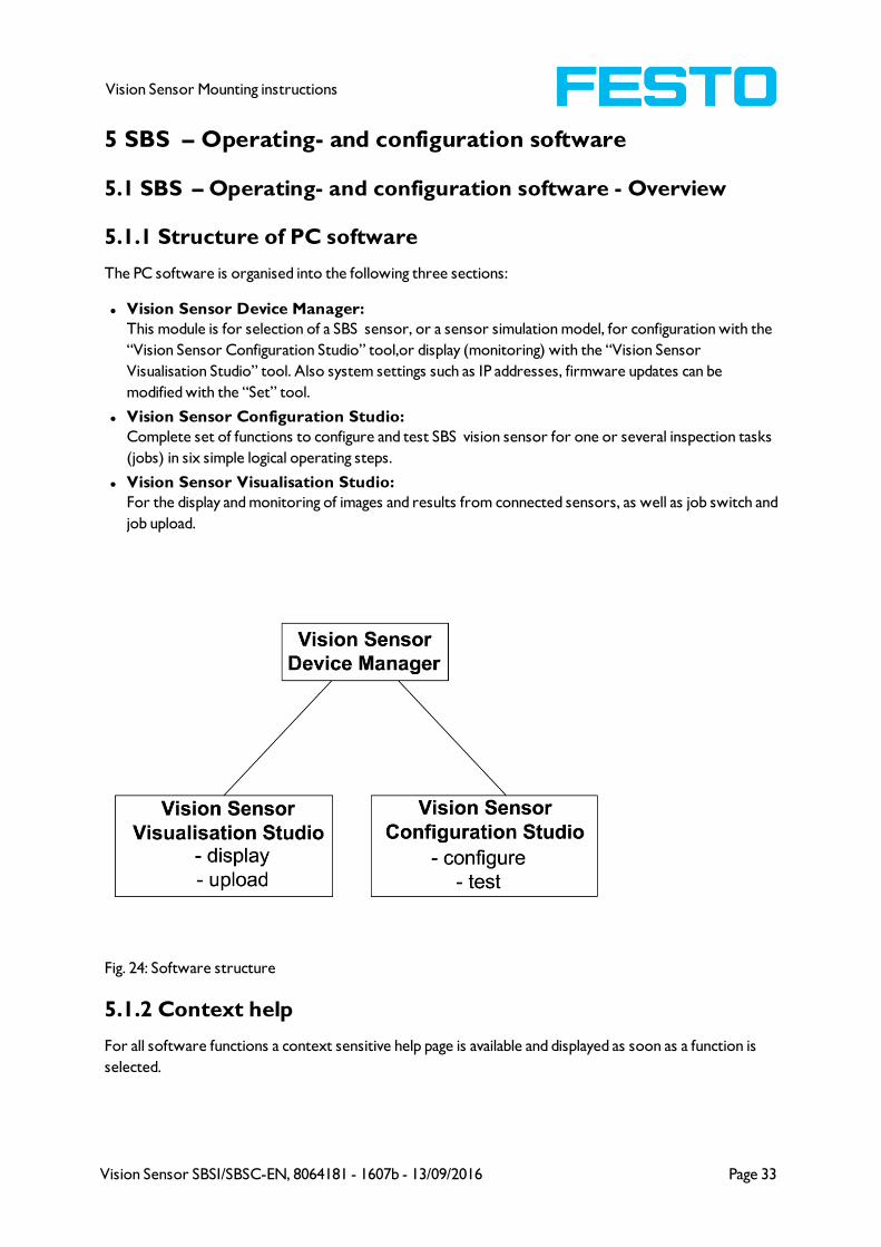
The PC software is organised into the following three sections:
l Vision Sensor Device Manager:
This module is for selection of a SBS sensor, or a sensor simulation model, for configuration with the
“Vision Sensor Configuration Studio” tool,or display (monitoring) with the “Vision Sensor
Visualisation Studio” tool. Also system settings such as IP addresses, firmware updates can be
modified with the “Set” tool.
l Vision Sensor Configuration Studio:
Complete set of functions to configure and test SBS vision sensor for one or several inspection tasks
(jobs) in six simple logical operating steps.
l Vision Sensor Visualisation Studio:
For the display and monitoring of images and results from connected sensors, as well as job switch and
job upload.
Fig. 24: Software structure
5.1.2 Context help
For all software functions a context sensitive help page is available and displayed as soon as a function is
selected.
Vision Sensor SBSI/SBSC-EN, 8064181 - 1607b - 13/09/2016 Page 33

Vision Sensor Mounting instructions
All available help pages can be viewed by pressing the Help- button („?“ symbol) or by double click to the
online help window. There you also can do a keyword search. In comparison to the context help the size
of this help window can be enlarged to view longer text more comfortable.
Used open source software: Open Source Licences (Page 3)
13/09/2016
5.2 SBS – Operating- and configuration software –
Short introduction
(Example: Object sensor)
5.2.1 SBS, Short introduction, Starting the software
This short guide explains step by step the procedure for setting an example inspection task on the vision
sensor
To start the SBS application click to the desktop icon "SBS Vision Sensor“.
Fig. 25: Icon SBS
5.2.2 Vision Sensor Device Manager: Open sensors or sensor
simulation / Passwords
In this program, you can select a sensor or a sensor simulation for configuration or display (monitoring)
and carry out different basic settings.
Next topic: Vision Sensor Configuration Studio: Setting sensor, Job (Page 38)
Configuring or displaying sensors
In order to open a sensor for configuration or display, select with a single left mouse click the required
sensor in the "Active sensors“ list, then click on the button "Config“ to start the "Vision Sensor
Configuration Studio“ software, or on the button "View“ for the "Vision Sensor Visualisation Studio“
software.
Sensor simulation
To open a sensor for offline simulation, select the required sensor in the "Sensors for simulation mode“
list, then click on the button "Config“ to start the module "Vision Sensor Configuration Studio“. Vision
Sensor Visualisation Studio is not available for the simulation mode as there is no device to send the
images for display.
Page 34 Vision Sensor SBSI/SBSC-EN, 8064181 - 1607b - 13/09/2016

Vision Sensor Mounting instructions
Fig. 26: Vision Sensor Device Manager Overview
A) Active sensors
This list displays all the SBS vision sensors available on the network that can be controlled from the PC.
B) Sensors for simulation mode
All the sensors available for offline simulation are displayed here.
C) Add sensors via IP address
Sensors, which are not visible after starting the software or after clicking the "Find" button in Vision
Sensor Device Manager, can be add manually with eheir IP address, if they are available in the network (e.g.
after a gateway) and if the IP address is well-known. Via clicking the button "Add" such sensor con be
found and are added to the list of active sensors, in order to edit them.
D) Functions
l Find
Activates another search procedure on the network to locate SBS products
l Config
Configures a connected sensor or a sensor simulation
l View
Displays image or result data from a connected sensor
l Set
Edits network settings such as the sensor's IP address etc.
E) Context help
Context sensitive help
Vision Sensor SBSI/SBSC-EN, 8064181 - 1607b - 13/09/2016 Page 35

Vision Sensor Mounting instructions
5.2.3 Passwords
When first started-up after installation, password entry is completely deactivated and auto login is preset
to administrator.
If parameter settings are to be protected from unauthorised access, passwords should be given for the
"Admin“ and "User“ password levels, see below. This can be called up via the menu bar File / User
administration or via the button with the key symbol in the toolbar.
Fig. 27: Password button
5.2.4 Password levels:
Fig. 28: Password levels
Password levelVision Sensor Device
Manager
Vision Sensor
Configuration
Studio
Vision Sensor Visualisation
Studio
Administrator
passwordall functions all functions all functions
Worker
password
all functions except
- Config.
- Settings
- Update
none
all functions,
including Job Upload and Image
Recorder
User
(without any
password)
all functions except
- Config.
- Settings
- Update
noneonly display of images,
inspection results and statistics
Page 36 Vision Sensor SBSI/SBSC-EN, 8064181 - 1607b - 13/09/2016

Vision Sensor Mounting instructions
In order to be able to use the function "Config“ after the allocation of passwords, it is now necessary to
login by clicking on the toolbar login button, and then entering the assigned password.
Fig. 29: Login button
Fig. 30: Password input
Allocating an empty password means the password can be confirmed without any further entry.
Activation of the "Deactivate password request“ checkbox, permanently deactivates password request.
If passwords have been assigned and then forgotten, it is possible to reset passwords to delivery status by
reinstalling the software on the local PC.
Vision Sensor SBSI/SBSC-EN, 8064181 - 1607b - 13/09/2016 Page 37
Vision Sensor Mounting instructions
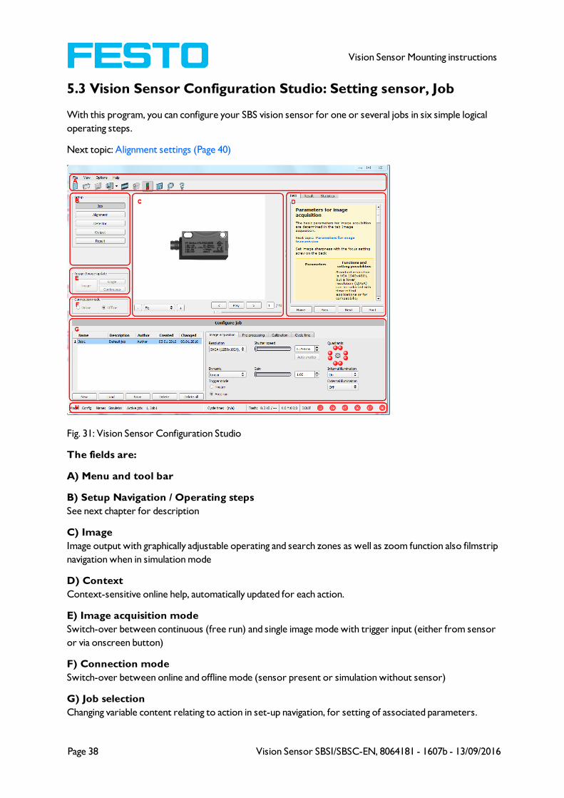
5.3 Vision Sensor Configuration Studio: Setting sensor, Job
With this program, you can configure your SBS vision sensor for one or several jobs in six simple logical
operating steps.
Next topic: Alignment settings (Page 40)
Fig. 31: Vision Sensor Configuration Studio
The fields are:
A) Menu and tool bar
B) Setup Navigation / Operating steps
See next chapter for description
C) Image
Image output with graphically adjustable operating and search zones as well as zoom function also filmstrip
navigation when in simulation mode
D) Context
Context-sensitive online help, automatically updated for each action.
E) Image acquisition mode
Switch-over between continuous (free run) and single image mode with trigger input (either from sensor
or via onscreen button)
F) Connection mode
Switch-over between online and offline mode (sensor present or simulation without sensor)
G) Job selection
Changing variable content relating to action in set-up navigation, for setting of associated parameters.
Page 38 Vision Sensor SBSI/SBSC-EN, 8064181 - 1607b - 13/09/2016
Vision Sensor Mounting instructions
H) Status bar
Different status information including Mode / Name of SBS / Active job. In Run Mode: Cycle time / cursor
x/y location and pixel intensity / individual I/O on /off indication (like configured in "Output/Digital
output").
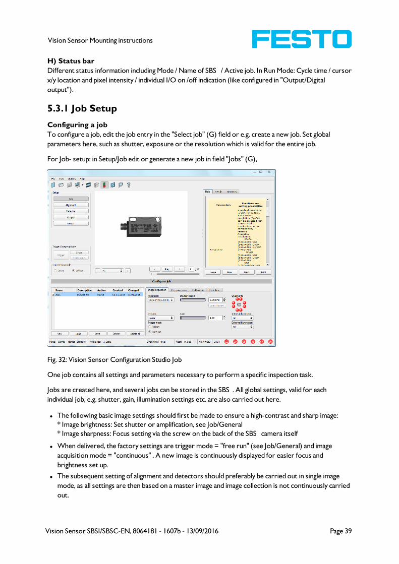
5.3.1 Job Setup
Configuring a job
To configure a job, edit the job entry in the "Select job" (G) field or e.g. create a new job. Set global
parameters here, such as shutter, exposure or the resolution which is valid for the entire job.
For Job- setup: in Setup/Job edit or generate a new job in field "Jobs" (G),
Fig. 32: Vision Sensor Configuration Studio Job
One job contains all settings and parameters necessary to perform a specific inspection task.
Jobs are created here, and several jobs can be stored in the SBS . All global settings, valid for each
individual job, e.g. shutter, gain, illumination settings etc. are also carried out here.
l The following basic image settings should first be made to ensure a high-contrast and sharp image:
* Image brightness: Set shutter or amplification, see Job/General
* Image sharpness: Focus setting via the screw on the back of the SBS camera itself
l When delivered, the factory settings are trigger mode = "free run" (see Job/General) and image
acquisition mode = "continuous" . A new image is continuously displayed for easier focus and
brightness set up.
l The subsequent setting of alignment and detectors should preferably be carried out in single image
mode, as all settings are then based on a master image and image collection is not continuously carried
out.
Vision Sensor SBSI/SBSC-EN, 8064181 - 1607b - 13/09/2016 Page 39
Vision Sensor Mounting instructions
l Alignment and multiple different detectors can subsequently be defined within one job to solve an
inspection task.
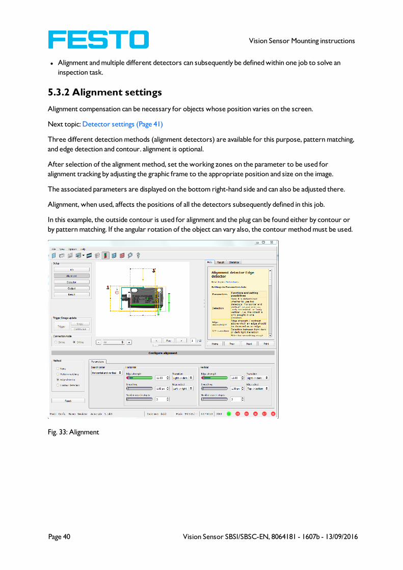
5.3.2 Alignment settings
Alignment compensation can be necessary for objects whose position varies on the screen.
Next topic: Detector settings (Page 41)
Three different detection methods (alignment detectors) are available for this purpose, pattern matching,
and edge detection and contour. alignment is optional.
After selection of the alignment method, set the working zones on the parameter to be used for
alignment tracking by adjusting the graphic frame to the appropriate position and size on the image.
The associated parameters are displayed on the bottom right-hand side and can also be adjusted there.
Alignment, when used, affects the positions of all the detectors subsequently defined in this job.
In this example, the outside contour is used for alignment and the plug can be found either by contour or
by pattern matching. If the angular rotation of the object can vary also, the contour method must be used.
Fig. 33: Alignment
Page 40 Vision Sensor SBSI/SBSC-EN, 8064181 - 1607b - 13/09/2016

Vision Sensor Mounting instructions
5.3.3 Detector settings
Different detectors can be selected and adjusted to solve an inspection task. First the required detector is
selected in the dialog box shown below.
Fig. 34: Detector list, Object sensor
Then the working and search zones are graphically set on the screen. If “teach zones” (red outline) exist,
they are taught immediately after completion of the settings. All the detectors defined in this job are
shown in the bottom left-hand corner. The parameters of the currently selected detector are shown in
the bottom right-hand corner and can be adjusted there.
If other parameters are to be checked on the same part, many other detectors can be created as
described above by clicking on "New".
In the example two brightness detectors are defined to check the presence of metal contacts in a plastic
connector housing.
Detector 1: contact found (brightness value is in defined range as the shiny metal contact is mounted)
result positive.
Detector 2: contact not found (brightness value out of defined range, as only weak reflection from the
black plastic housing background) result negative.
Vision Sensor SBSI/SBSC-EN, 8064181 - 1607b - 13/09/2016 Page 41
Vision Sensor Mounting instructions
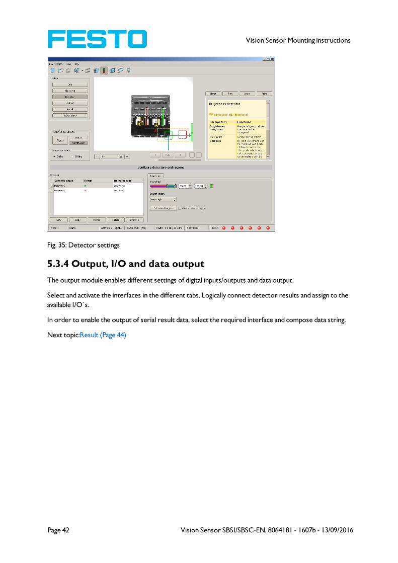
Fig. 35: Detector settings
5.3.4 Output, I/O and data output
The output module enables different settings of digital inputs/outputs and data output.
Select and activate the interfaces in the different tabs. Logically connect detector results and assign to the
available I/O´s.
In order to enable the output of serial result data, select the required interface and compose data string.
Next topic:Result (Page 44)
Page 42 Vision Sensor SBSI/SBSC-EN, 8064181 - 1607b - 13/09/2016
Vision Sensor Mounting instructions
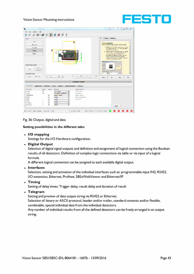
Fig. 36: Output, digital and data
Setting possibilities in the different tabs:
l I/O mapping
Settings for the I/O Hardware configuration.
l Digital Output
Selection of digital signal outputs and definition and assignment of logical connection using the Boolean
results of all detectors. Definition of complex logic connections via table or via input of a logical
formula.
A different logical connection can be assigned to each available digital output.
l Interfaces
Selection, setting and activation of the individual interfaces such as: programmable input IN2, RS422,
I/O extension, Ethernet, Profinet, SBSxWebViewer and Ethernet/IP
l Timing
Setting of delay times: Trigger delay, result delay and duration of result
l Telegram
Setting and preview of data output string via RS422 or Ethernet.
Selection of: binary or ASCII protocol, header and/or trailer, standard contents and/or flexible,
combinable, special individual data from the individual detectors.
Any number of individual results from all the defined detectors can be freely arranged in an output
string.
Vision Sensor SBSI/SBSC-EN, 8064181 - 1607b - 13/09/2016 Page 43
Vision Sensor Mounting instructions
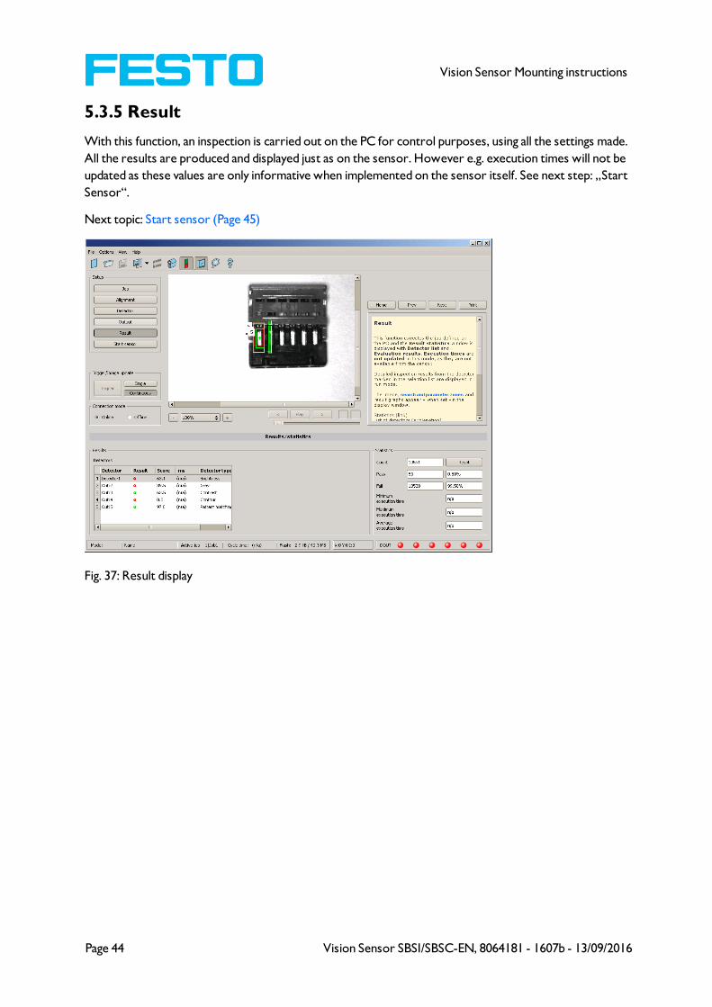
5.3.5 Result
With this function, an inspection is carried out on the PC for control purposes, using all the settings made.
All the results are produced and displayed just as on the sensor. However e.g. execution times will not be
updated as these values are only informative when implemented on the sensor itself. See next step: „Start
Sensor“.
Next topic: Start sensor (Page 45)
Fig. 37: Result display
Page 44 Vision Sensor SBSI/SBSC-EN, 8064181 - 1607b - 13/09/2016

Vision Sensor Mounting instructions
5.3.6 Start sensor
When this function is activated, all settings are transferred to the sensor, stored in the flash memory and
carried out in e.g. in free run or in triggered mode according to the settings made. All information in the
list of detectors, result field or under „Statistics“ is updated here.
If using “triggered mode” then a trigger will be required from the external control system, alternatively a
‘software’ trigger can be sent using the Trigger button the left hand side of the image area.
Next topic: Vision Sensor Visualisation Studio, display images and results (Page 46)
Fig. 38: Start sensor
Vision Sensor SBSI/SBSC-EN, 8064181 - 1607b - 13/09/2016 Page 45
Vision Sensor Mounting instructions
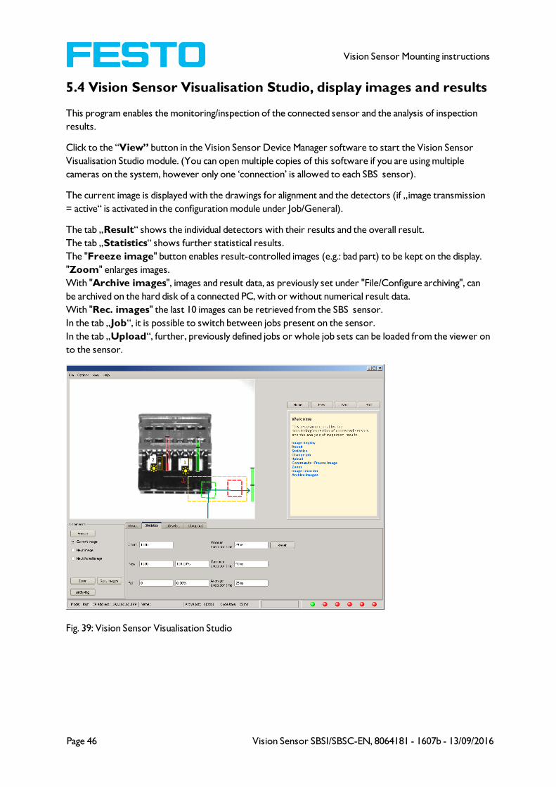
5.4 Vision Sensor Visualisation Studio, display images and results
This program enables the monitoring/inspection of the connected sensor and the analysis of inspection
results.
Click to the “View” button in the Vision Sensor Device Manager software to start the Vision Sensor
Visualisation Studio module. (You can open multiple copies of this software if you are using multiple
cameras on the system, however only one ‘connection’ is allowed to each SBS sensor).
The current image is displayed with the drawings for alignment and the detectors (if „image transmission
= active“ is activated in the configuration module under Job/General).
The tab „Result“ shows the individual detectors with their results and the overall result.
The tab „Statistics“ shows further statistical results.
The "Freeze image" button enables result-controlled images (e.g.: bad part) to be kept on the display.
"Zoom" enlarges images.
With "Archive images", images and result data, as previously set under "File/Configure archiving", can
be archived on the hard disk of a connected PC, with or without numerical result data.
With "Rec. images" the last 10 images can be retrieved from the SBS sensor.
In the tab „Job“, it is possible to switch between jobs present on the sensor.
In the tab „Upload“, further, previously defined jobs or whole job sets can be loaded from the viewer on
to the sensor.
Fig. 39: Vision Sensor Visualisation Studio
Page 46 Vision Sensor SBSI/SBSC-EN, 8064181 - 1607b - 13/09/2016

Vision Sensor Mounting instructions
6 Technical Data
Electrical data
Operating voltage UB 24 V DC , -25% / +10%
Residual ripple < 5 Vss
Current consumption (no I/O) ≤ 200 mA
All inputs PNP / NPN High > UB - 1 V, Low < 3 V
Input resistance > 20 kOhm
Encoder input High > 4 V
Outputs PNP / NPN
Maximum output current (per output) 50 mA, Ejector (Pin 12 / RDBU) 100 mA
Short-circuit protection (all outputs) yes
Inductive load typ.: Relays 17K / 2H, pneumatic valve 1.4K / 190mH
Protection against inverse polarity yes
Interfaces SBS -XX-Standard
Interfaces SBS -XX-Advanced
Ethernet (LAN)
Ethernet (LAN), RS422/RS232
Readiness delay Typ. 13 s after power on
Optical data
Number of pixels , chip size, pixel sizeSBS - R3B...: 736 (H) x 480 (V), 1/3", 6,0 um square
SBS - R2B...: 1280 (H) x 1024 (V), 1/1.8", 5,5 um square
Technology CMOS (mono / color)
Integrated scan illumination 8 LEDs (except C-Mount)
Integrated lens, focal length 6, 12 or 25 mm, adjustable focus
R3B R3B R2B
Lens (adjustable to infinity) 6 12 12
Min. scan distance 6 30 30
Min. field of view X x Y 5 x 4 8 x 6 16 x 13
Mechanical data
Length x width x height 65 x 45 x 45 mm (without plug)
Weight approx.160 g
Vibration / shock EN 60947-5-2
Vision Sensor SBSI/SBSC-EN, 8064181 - 1607b - 13/09/2016 Page 47
Vision Sensor Mounting instructions
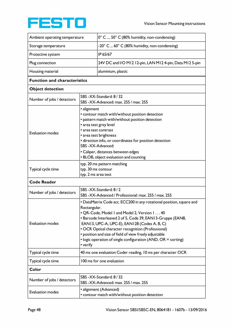
Ambient operating temperature 0° C .... 50° C (80% humidity, non-condensing)
Storage temperature -20° C ... 60° C (80% humidity, non-condensing)
Protective system IP 65/67
Plug connection 24V DC and I/O M12 12-pin, LAN M12 4-pin, Data M12 5-pin
Housing material aluminium, plastic
Function and characteristics
Object detection
Number of jobs / detectorsSBS -XX-Standard: 8 / 32
SBS -XX-Advanced: max. 255 / max. 255
Evaluation modes
• alignment
• contour match with/without position detection
• pattern match with/without position detection
• area test grey level
• area test contrast
• area test brightness
• direction info, or coordinates for position detection
SBS -XX-Advanced:
• Caliper, distances between edges
• BLOB, object evaluation and counting
Typical cycle time
typ. 20 ms pattern matching
typ. 30 ms contour
typ. 2 ms area test
Code Reader
Number of jobs / detectorsSBS -XX-Standard: 8 / 2
SBS -XX-Advanced / Professional: max. 255 / max. 255
Evaluation modes
• DataMatrix Code acc. ECC200 in any rotational position, square and
Rectangular.
• QR-Code, Model 1 and Model 2, Version 1 . . . 40
• Barcode Interleaved 2 of 5, Code 39, EAN13-Gruppe (EAN8,
EAN13, UPC-A, UPC-E), EAN128 (Codes A, B, C)
• OCR Optical character recognition (Professional)
• position and size of field of view freely adjustable
• logic operation of single configuration (AND, OR = sorting)
• verify
Typical cycle time 40 ms one evaluation Coder reading, 10 ms per character OCR
Typical cycle time 100 ms for one evaluation
Color
Number of jobs / detectorsSBS -XX-Standard: 8 / 32
SBS -XX-Advanced: max. 255 / max. 255
Evaluation modes• alignment (Advanced)
• contour match with/without position detection
Page 48 Vision Sensor SBSI/SBSC-EN, 8064181 - 1607b - 13/09/2016

Vision Sensor Mounting instructions
• pattern match with/without position detection
• area test grey level
• area test contrast
• area test brightness
• direction info, or coordinates for position detection
• color value
• color area
• color list
Typical cycle time
typ. 30 ms pattern match
typ. 60 ms contour
typ. 2 ms brightness
typ. 2 ms contrast
typ. 2 ms grey threshold
typ. 2 ms colour value
typ. 30 ms colour area
typ. 2 ms colour list
Universal
Number of jobs / detectors SBS R2B-ALL ... : max. 255 / max. 255
Evaluation modes /
Typical cycle time
All function as
l Object
l Code Reader
l Color
Vision Sensor SBSI/SBSC-EN, 8064181 - 1607b - 13/09/2016 Page 49

Vision Sensor Mounting instructions
7 Type key
Page 50 Vision Sensor SBSI/SBSC-EN, 8064181 - 1607b - 13/09/2016


