VISUAL CUES ON LANDING SITES (MANOEUVRING, TOUCHDOWN AND POSITIONING MARKINGS) Changes: Added ‘above’ the line rather than ‘over’ Page 1 of 17 26 th April 2011 1. INTRODUCTION The helicopter is one of the more versatile of aircraft and can operate to/from a space little larger than its overall length. The smaller the site, and the less known about the hazards presented by obstacles and surface conditions, the more risk will be associated with its use. The risk presented by such hazards can be reduced when: a. the size is substantially beyond the minimum required size; or b. sufficient knowledge about the site is available - and this knowledge is provided as information (that contained on templates and that which is provided as markings on the site); and c. visual cues and positional markings are present. 2. BASIC REQUIREMENTS OF ANY LANDING SITE The basic requirements for a landing site can be separated into two types: a. those associated with the airspace surrounding the site; and b. those which are associated with the surface of the site. 2.1 Airspace Requirements Airspace requirements are mainly concerned with ensuring that approach and departure paths: are free from obstacles that may conflict with the potential helicopter profiles; avoid areas/directions which might be a source of irritation/danger to third parties; and, permit a sequencing system that can minimise the risks associated with simultaneous operations. As this paper is primarily concerned with the facilities on the surface, no more is said on this subject; further information can be found in Annex 14 Volume II – Heliports, or local regulations and/or guidance. 2.2 Surface Requirements It is useful - for the purpose of discussion - to divide the site into four main categories: a. The surface over which the final approach and take off is conducted (FATO) b. The surface on which the touch-down (and lift-off) is conducted (TLOF) c. The surface for parking – and manoeuvring when parking (stands) d. The surface for manoeuvring – when outside stands/FATO (taxiways and associated taxi- routes) Clearly there will be sites where a defined area is used for more than one purpose or they may be co-located – for example on a helideck, the FATO and TLOF. With respect to all of these areas we are principally interested in: the size and the shape; the conditions of the surface over which we may be moving and on which we will touch-down; and the proximity of obstacles – natural and artificial, temporary or permanent. It is necessary to establish the basic requirement for any of the ‘defined’ areas of a heliport. In establishing the requirement, it should include any limitation which might be present and the
Transcript
VISUAL CUES ON LANDING SITES (MANOEUVRING, TOUCHDOWN AND POSITIONING MARKINGS)
Changes: Added ‘above’ the line rather than ‘over’
Page 1 of 17
26th April 2011
1. INTRODUCTION The helicopter is one of the more versatile of aircraft and can operate to/from a space little larger than its overall length. The smaller the site, and the less known about the hazards presented by obstacles and surface conditions, the more risk will be associated with its use. The risk presented by such hazards can be reduced when:
a. the size is substantially beyond the minimum required size; or
b. sufficient knowledge about the site is available - and this knowledge is provided as information (that contained on templates and that which is provided as markings on the site); and
c. visual cues and positional markings are present.
2. BASIC REQUIREMENTS OF ANY LANDING SITE The basic requirements for a landing site can be separated into two types:
a. those associated with the airspace surrounding the site; and
b. those which are associated with the surface of the site.
2.1 Airspace Requirements Airspace requirements are mainly concerned with ensuring that approach and departure paths: are free from obstacles that may conflict with the potential helicopter profiles; avoid areas/directions which might be a source of irritation/danger to third parties; and, permit a sequencing system that can minimise the risks associated with simultaneous operations.
As this paper is primarily concerned with the facilities on the surface, no more is said on this subject; further information can be found in Annex 14 Volume II – Heliports, or local regulations and/or guidance.
2.2 Surface Requirements It is useful - for the purpose of discussion - to divide the site into four main categories:
a. The surface over which the final approach and take off is conducted (FATO)
b. The surface on which the touch-down (and lift-off) is conducted (TLOF)
c. The surface for parking – and manoeuvring when parking (stands)
d. The surface for manoeuvring – when outside stands/FATO (taxiways and associated taxi-routes)
Clearly there will be sites where a defined area is used for more than one purpose or they may be co-located – for example on a helideck, the FATO and TLOF.
With respect to all of these areas we are principally interested in: the size and the shape; the conditions of the surface over which we may be moving and on which we will touch-down; and the proximity of obstacles – natural and artificial, temporary or permanent.
It is necessary to establish the basic requirement for any of the ‘defined’ areas of a heliport. In establishing the requirement, it should include any limitation which might be present and the
VISUAL CUES ON LANDING SITES (MANOEUVRING, TOUCHDOWN AND POSITIONING MARKINGS)
Changes: Added ‘above’ the line rather than ‘over’
Page 2 of 17
26th April 2011
protection which is afforded – with or without such limitations. In some, protection is likely to be conditional upon the conditions which are applied.
2.1 Stands The Stand is an area which contains a circle of 1.2D of the design helicopter. This dimension was established on the assumption that a helicopter turns around its rotor centroid. As can be seen from Figure 1, with such a turn the tail prescribes an arc around the perimeter of the Stand whilst the front of the disc remains at a distance of 0.2D:
Figure 1 – Helicopter located within a 1.2D Stand (rotating around rotor centroid)
With the (empirical established) diameter of the rotor being 0.83 of the D of the helicopter, it can also be seen that, when positioning in this way, there is a space of 0.23D each side from the perimeter.
If the helicopter is positioned accurately in the centre of the Stand and then turned around its centre point, all parts can be kept 0.1D from the perimeter - as shown in Figure 2 below:
Figure 2 – Helicopter located within a 1.2D Stand (rotating around its centre point)
With either placing scheme, if the helicopter is not moving, it can be regarded as an object with respect to helicopters manoeuvring in an adjacent Stand. However, all placing schemes do require that the helicopter is positioned accurately or the safety distances will be eroded.
In order to permit the helicopter to manoeuvre and permit a margin of error, it is necessary to place a protection area around the Stand. In the Second Edition - 1995 of ICAO Annex 14, the size of the Stand was 1D and the minimum clearance between a helicopter using a Stand and an object, or part of a helicopter on an adjacent Stand was stated as 0.5D. With the increase of the size of the Stand to 1.2D, it was logical to reduce the protection area beyond a Stand to 0.4D (thus a Stand plus its protection zone remained as 2.0D).
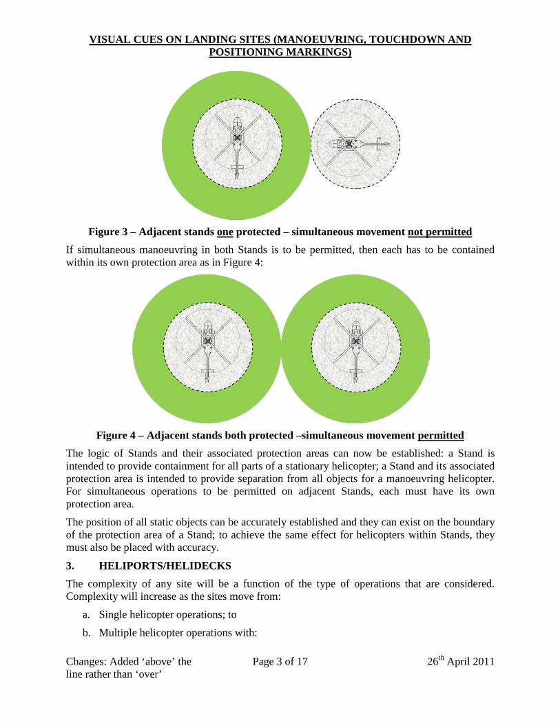
We can now see that to permit manoeuvring in one of two adjacent Stands, at least one should have a protection area as shown in Figure 3:
VISUAL CUES ON LANDING SITES (MANOEUVRING, TOUCHDOWN AND POSITIONING MARKINGS)
Changes: Added ‘above’ the line rather than ‘over’
Page 3 of 17
26th April 2011
Figure 3 – Adjacent stands one protected – simultaneous movement not permitted
If simultaneous manoeuvring in both Stands is to be permitted, then each has to be contained within its own protection area as in Figure 4:
Figure 4 – Adjacent stands both protected –simultaneous movement permitted
The logic of Stands and their associated protection areas can now be established: a Stand is intended to provide containment for all parts of a stationary helicopter; a Stand and its associated protection area is intended to provide separation from all objects for a manoeuvring helicopter. For simultaneous operations to be permitted on adjacent Stands, each must have its own protection area.
The position of all static objects can be accurately established and they can exist on the boundary of the protection area of a Stand; to achieve the same effect for helicopters within Stands, they must also be placed with accuracy.
3. HELIPORTS/HELIDECKS The complexity of any site will be a function of the type of operations that are considered. Complexity will increase as the sites move from:
a. Single helicopter operations; to
b. Multiple helicopter operations with:
VISUAL CUES ON LANDING SITES (MANOEUVRING, TOUCHDOWN AND POSITIONING MARKINGS)
Changes: Added ‘above’ the line rather than ‘over’
Page 4 of 17
26th April 2011
• Non-simultaneous operations; or
• Simultaneous operations
3.1 Rationale for Markings The markings on a site are generally grouped into two types:
a. those which provide information; and
b. those which provide visual cues to the pilot.
3.1.1 Provision of Information Information can be provided in plain language (for the location), or using standard coding (boxes containing maximum size or weight1). For helidecks, the presence of the ‘chevron’ marker also indicates the boundary between the obstacles permitted to be in the Limited Obstacle Sector and the Obstacle Free Sector (seen on the right of the deck in Figure 1 and at the bottom in Figure 2).
Figure 1 – Helideck Markings by Day
3.1.2 Provision of Visual Cues Visual cues for pilots can include ‘aiming points’ (provided on FATOs where touchdown is not anticipated); guidance lines for taxying (both ground and hover); shoulder lines (stop lines); and touchdown and positioning markings. These ‘manoeuvring’ markings provide protection from: obstacles; arriving/departing helicopters; other helicopters parked or manoeuvring; and ground services (permanent and portable equipment).
1 The codes indicating size and mass limitations may be presented either in metric (metres and kilograms) or imperial (feet and pounds).
VISUAL CUES ON LANDING SITES (MANOEUVRING, TOUCHDOWN AND POSITIONING MARKINGS)
Changes: Added ‘above’ the line rather than ‘over’
Page 5 of 17
26th April 2011
Figure 2 – Helideck Markings by Night (experimental configuration)
Generally, visual cues/markings for pilots do not provide information about the (actual) separation from hazards/obstacles on which protection is based; that can only be ascertained by knowledge and understanding of the regulation in which they are stipulated.
Protection is based upon the largest helicopter the site is expected to serve (which is stated in the documentation and in the limitations box on the FATO) and is defined in ‘proportions’ of the design ‘D’ (e.g. 0.25D, 0.5D where D = largest dimension of the helicopter with the rotors running) or ‘RD’ (e.g. 0.5RD where the Rotor Diameter (RD) is generally accepted to be 0.83 of ‘D’). In general terms, RD is used for lateral protection and D when lateral and/or longitudinal protection is provided (for example in turning manoeuvres).
Protection from obstacles is always dependent upon accurate manoeuvring and positioning of the helicopter.
3.2 Commonality of Markings Visual cues/markings at an operating site are intended for the pilot; it is therefore important that when marking schemes are used, they should be common/universal and can be applied to all helicopters using that (or, in fact, any) site.
In order to achieve the maximum efficiency of space, a distinction between uni/bi-directional and omni-directional operations should be made; this can be achieved with the use of guidance lines and stop lines for the former and circles for the latter2.
2 The circle is merely the transformation of the stop line principle into a omni-directional (360°) context.
VISUAL CUES ON LANDING SITES (MANOEUVRING, TOUCHDOWN AND POSITIONING MARKINGS)
Changes: Added ‘above’ the line rather than ‘over’
Page 6 of 17
26th April 2011
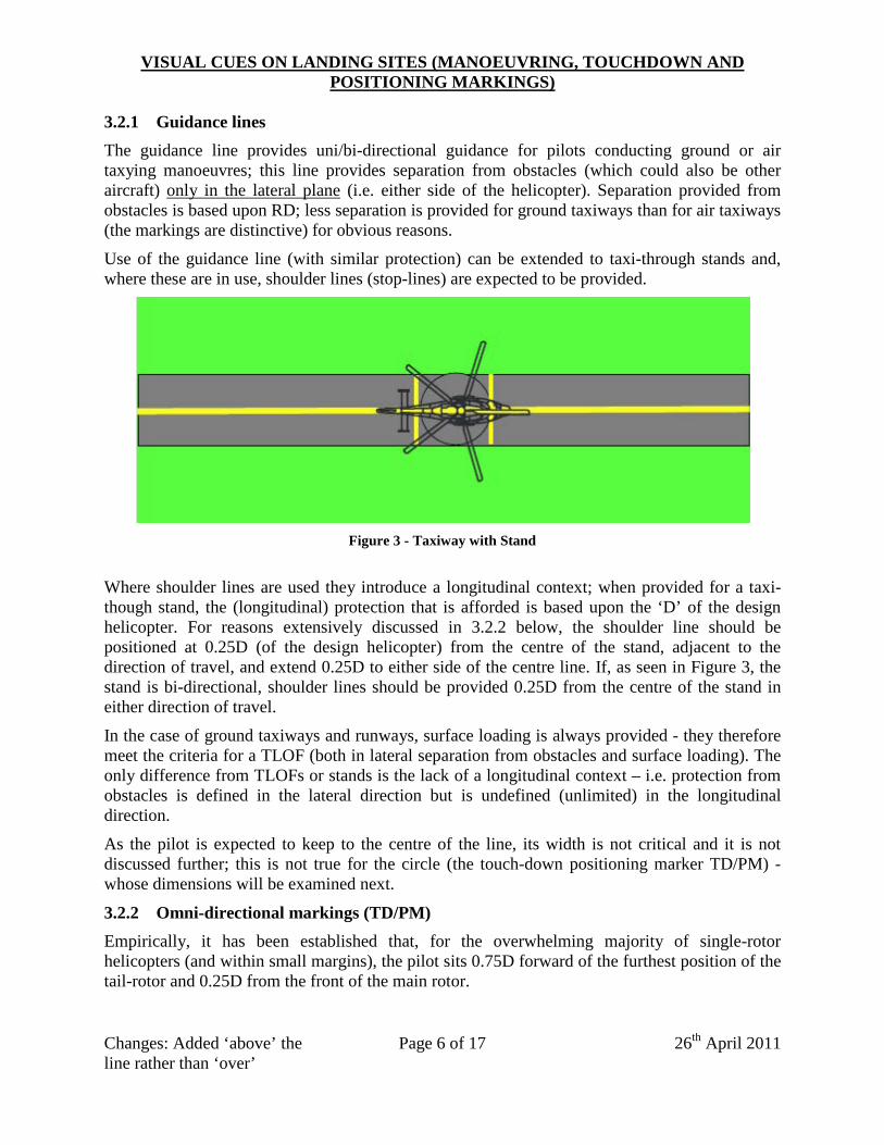
3.2.1 Guidance lines The guidance line provides uni/bi-directional guidance for pilots conducting ground or air taxying manoeuvres; this line provides separation from obstacles (which could also be other aircraft) only in the lateral plane (i.e. either side of the helicopter). Separation provided from obstacles is based upon RD; less separation is provided for ground taxiways than for air taxiways (the markings are distinctive) for obvious reasons.
Use of the guidance line (with similar protection) can be extended to taxi-through stands and, where these are in use, shoulder lines (stop-lines) are expected to be provided.
Figure 3 - Taxiway with Stand
Where shoulder lines are used they introduce a longitudinal context; when provided for a taxi-though stand, the (longitudinal) protection that is afforded is based upon the ‘D’ of the design helicopter. For reasons extensively discussed in 3.2.2 below, the shoulder line should be positioned at 0.25D (of the design helicopter) from the centre of the stand, adjacent to the direction of travel, and extend 0.25D to either side of the centre line. If, as seen in Figure 3, the stand is bi-directional, shoulder lines should be provided 0.25D from the centre of the stand in either direction of travel.
In the case of ground taxiways and runways, surface loading is always provided - they therefore meet the criteria for a TLOF (both in lateral separation from obstacles and surface loading). The only difference from TLOFs or stands is the lack of a longitudinal context – i.e. protection from obstacles is defined in the lateral direction but is undefined (unlimited) in the longitudinal direction.
As the pilot is expected to keep to the centre of the line, its width is not critical and it is not discussed further; this is not true for the circle (the touch-down positioning marker TD/PM) - whose dimensions will be examined next.
3.2.2 Omni-directional markings (TD/PM) Empirically, it has been established that, for the overwhelming majority of single-rotor helicopters (and within small margins), the pilot sits 0.75D forward of the furthest position of the tail-rotor and 0.25D from the front of the main rotor.
VISUAL CUES ON LANDING SITES (MANOEUVRING, TOUCHDOWN AND POSITIONING MARKINGS)
Changes: Added ‘above’ the line rather than ‘over’
Page 7 of 17
26th April 2011
This principle can be utilised in the provision of marking schemes; if a circle of 0.5D of any single-rotor helicopter is drawn, with the pilot on the inner circumference of the TD/PM and with the helicopter continuously aligned on the diameter (in any direction) of the circle, the helicopter will occupy the smallest combined space possible. Thus, any landing site of 1D can contain all parts of the helicopter (within a very small margin) when the 0.5D circle is established on the centre of the site and the pilot is correctly positioned (see this in diagram form in Figure 4 below).
Figure 4 - Effectiveness of Positioning using the TD/P Marking
The main proviso is that “the site must be of sufficient size to contain an area within which can be drawn a circle of diameter not less than 1.0 times D of the largest helicopter the site is intended to serve, where D is the largest dimension of the helicopter when the rotors are running”3.
NB: Regardless of the shape of the site, this circle must first be established before any of the provisions for marking can be made.
The 1D circle will contain the helicopter; hence, obstacle clearance has to be provided by safety areas surrounding the FATO/Stand i.e. beyond the 1D circle.
3.2.3 Construction and positioning of the TD/PM on a Helideck As has already been stated, the TD/PM should be a circle of 0.5D; this is the inner circumference of the TD/PM marking whose line width should be 1m. The centre of the TD/PM should be located at the centre of the TLOF. In Figure 5 below, this arrangement is shown for a helideck with a FATO ( D) of 22m; the circle in which the FATO is contained in shown (for the purpose of this paper only) as a red circle.
3 Which is text taken directly from ICAO Annex 14 Volume II.
VISUAL CUES ON LANDING SITES (MANOEUVRING, TOUCHDOWN AND POSITIONING MARKINGS)
Changes: Added ‘above’ the line rather than ‘over’
Page 8 of 17
26th April 2011
Figure 5 - Helideck with Central TD/P Marking
Preliminary statistical analysis has also shown that, if the pilot is correctly positioned on the TD/PM the undercarriage (skids, tricycle undercarriages, and tail-draggers) can be contained within a circle of 0.83D centred on the site (i.e. concentric with the TD/PM)4.
3.2.4 The Offset Markings In CAP 437 and ICAO Annex 14, there is a provision that the TD/PM may be offset away from the Obstacle Sector by up to 0.1D as shown in Figure 6 below; this provides an increased margin from the known obstacles in the Limited Obstacle Sector (LOS). It can be seen that, if this offset is used, the undercarriage containment circle of 0.83D (equating to the minimum permitted size of the TLOF - shown as the black circle in the diagram) could, in the worst case, be 0.015D off the landing site. This would only present problems if the operating helicopter was one with its undercarriage configuration at the extreme end of the distribution (the two at the extreme of the distribution were the S70 and the AS360 – both tail-draggers). However, containment of the undercarriage does (for some helicopters) depend upon the pilot accurately positioning the helicopter and leaves little margin for error.
Figure 6 - Helideck with Offset TD/P Marking
4 This fact is used when permitting the use of undersized sites - i.e. those which are less than 1D.
VISUAL CUES ON LANDING SITES (MANOEUVRING, TOUCHDOWN AND POSITIONING MARKINGS)
Changes: Added ‘above’ the line rather than ‘over’
Page 9 of 17
26th April 2011
4. USE AND ABUSE OF THE TD/PM ON A HELIDECK 4.1 Pilot Positioning when on a Helideck Clearly, separation from obstacle is only achieved when the pilot is correctly positioned on the inner diameter of the TD/PM circle. Discussion with pilots on this subject indicates that many do not understand the importance of the TD/PM marking (some not even knowing its basic purpose) or the dangers that might be present when the helicopter is not correctly positioned.
It has to be stressed that the correct positioning is achieved when the pilot is situated immediately above the inner circle of the TD/PM, not above the painted portion of the line (which could introduce a positioning error of up to 1m). Although it also may appear intuitive, putting the wheels inside the circle, or choosing a position on the deck to avoid obstacles, is always less safe than positioning correctly on the TD/PM.
Without a TD/PM – or if one is present but is ignored - the tail rotor can, without the pilot being aware of it, be located close to or even over obstacles; thus negating the requirement for a safe margin of clearance to be established. Even when correctly positioned, if a helicopter hovers in a nose-up attitude, the tail rotor can be close to obstacles.
Additionally, when facing towards the Limited Obstacle Sector, if not correctly positioned on the TD/PM, the tail wheel of a tail-dragger could be close to, or even off, the deck (particularly if the offset marking scheme is used – see Figure 6 above).
It is therefore imperative that:
a. The TD/PM is marked on the deck; and
b. Pilots are made aware of the dangers of not positioning correctly on the markings.
It should also be clearly understood that, even when the helicopter is of a size that is less than the design D of the site, the only time that the safety of the helicopter can be guaranteed is when the pilot is positioned correctly on the TD/PM. For any other positioning on the TLOF, although probable that there is clearance from obstructions, there is no certainty.
4.2 Manoeuvring to a Helideck The TD/PM also provides some visual cues when the pilot is making an approach to a helideck. As can be seen in Figure 7 below - taken from a recent accident report from the North Sea - making a final approach to the deck without taking notice, or making use, of the visual cues that are provided by the TD/PM can result in the tail of the aircraft being placed into the Limited Obstacle Sector.
The greyed-out helicopters at the top and bottom of the diagram show the safe routes to landing on the TLOF for two reasons: (1) the front of the TD/PM and deck-edge are being used as positioning references; and (2) from those positions, the Field of View (FOV) is at its widest (i.e. with an uninterupted view from the side window).
VISUAL CUES ON LANDING SITES (MANOEUVRING, TOUCHDOWN AND POSITIONING MARKINGS)
Changes: Added ‘above’ the line rather than ‘over’
Page 10 of 17
26th April 2011
Figure 7 - Accident Site with Potential Approach Directions
Even if flying to a helideck with no obstructions (e.g. a wellhead platform) or few obstructions, a straight-in approach presents a risk because FOV is at its worst when the visual cues are in the front window (the TD/PM will disappear from view when it sinks below the instrument panel). From the moment when the TD/PM has disappeared from view, positioning and obstacle clearance is being achieved only from a picture in the pilot’s memory.
4.2 Manoeuvring on the Helideck Manoeuvring on a helideck should be avoided whenever possible; if manoeuvring on a 1D deck, the ‘spot turn’ presents the most danger because turning around the mast - Figure 8 - or, even worse, the pilot – Figure 9 - could put the tail, and the main rotor, of the helicopter up to 0.25D into the Limited Obstacle Sector and/or place the undercarriage outside the 0.83D circle.
Figure 8 - Turning Around Mast
VISUAL CUES ON LANDING SITES (MANOEUVRING, TOUCHDOWN AND POSITIONING MARKINGS)
Changes: Added ‘above’ the line rather than ‘over’
Page 11 of 17
26th April 2011
Figure 9 - Turning Around Pilot
If it is necessary to turn the helicopter (for example if the wind has changed during a shut-down), the helicopter should be rotated with the pilot on the inner circumference of the TD/PM with the helicopter continuously aligned on the diameter of the circle. Thus for a 90º turn, the manoeuvre would be as shown in Figure 10:
Figure 10 - Turning Around TD/P Marking
5. HELIDECKS LESS THAN 1D Under the revised Annex 14 arrangements, it is possible, for helicopters up to 7,000lbs (3,175kg) to operate to helidecks with a 0.83D TLOF. If the appropriate rules for markings and positioning are observed, the additional hazards should be constrained to: the reduced visual cues afforded by the smaller landing site; and those associated with the reduction of the TLOF (shown diagrammatically in Figure 11 below).
VISUAL CUES ON LANDING SITES (MANOEUVRING, TOUCHDOWN AND POSITIONING MARKINGS)
Changes: Added ‘above’ the line rather than ‘over’
Page 12 of 17
26th April 2011
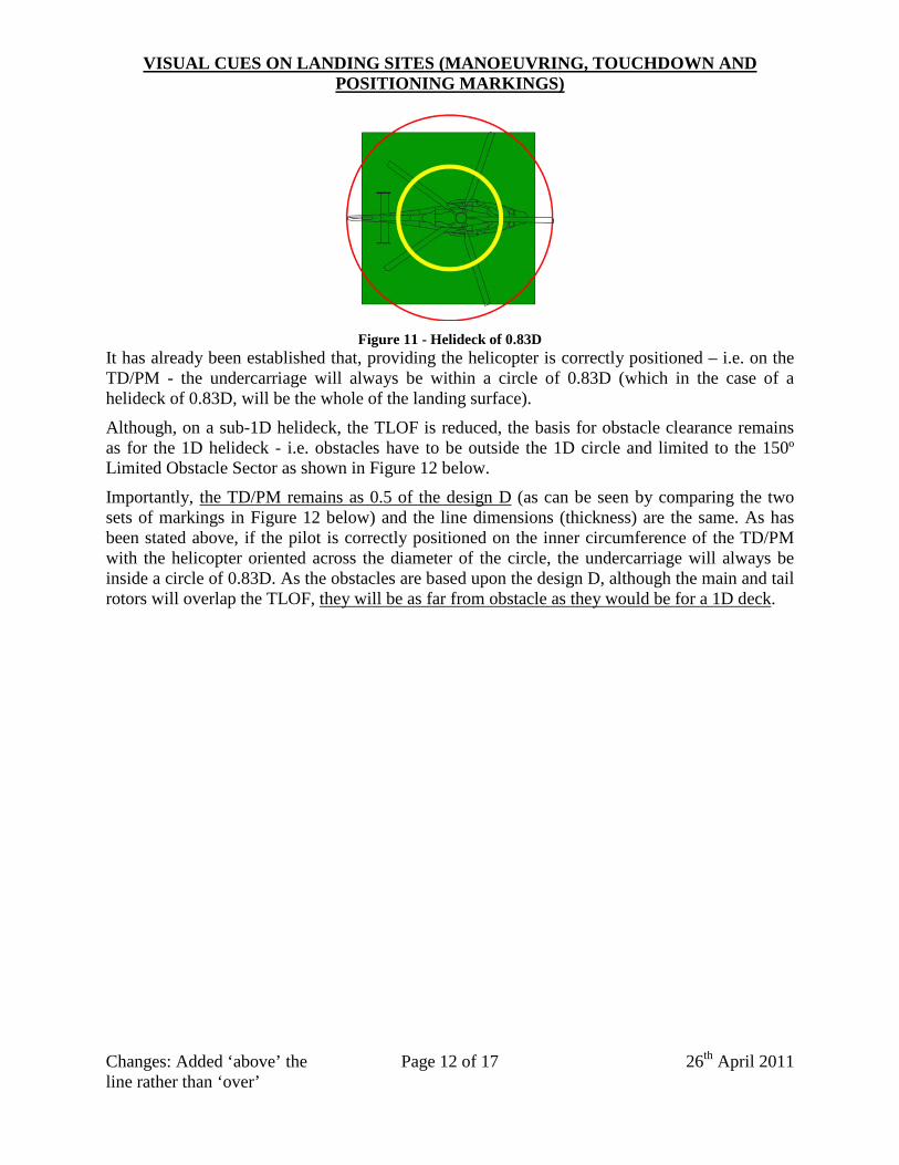
Figure 11 - Helideck of 0.83D
It has already been established that, providing the helicopter is correctly positioned – i.e. on the TD/PM - the undercarriage will always be within a circle of 0.83D (which in the case of a helideck of 0.83D, will be the whole of the landing surface).
Although, on a sub-1D helideck, the TLOF is reduced, the basis for obstacle clearance remains as for the 1D helideck - i.e. obstacles have to be outside the 1D circle and limited to the 150º Limited Obstacle Sector as shown in Figure 12 below.
Importantly, the TD/PM remains as 0.5 of the design D (as can be seen by comparing the two sets of markings in Figure 12 below) and the line dimensions (thickness) are the same. As has been stated above, if the pilot is correctly positioned on the inner circumference of the TD/PM with the helicopter oriented across the diameter of the circle, the undercarriage will always be inside a circle of 0.83D. As the obstacles are based upon the design D, although the main and tail rotors will overlap the TLOF, they will be as far from obstacle as they would be for a 1D deck.
VISUAL CUES ON LANDING SITES (MANOEUVRING, TOUCHDOWN AND POSITIONING MARKINGS)
Changes: Added ‘above’ the line rather than ‘over’
Page 13 of 17
26th April 2011
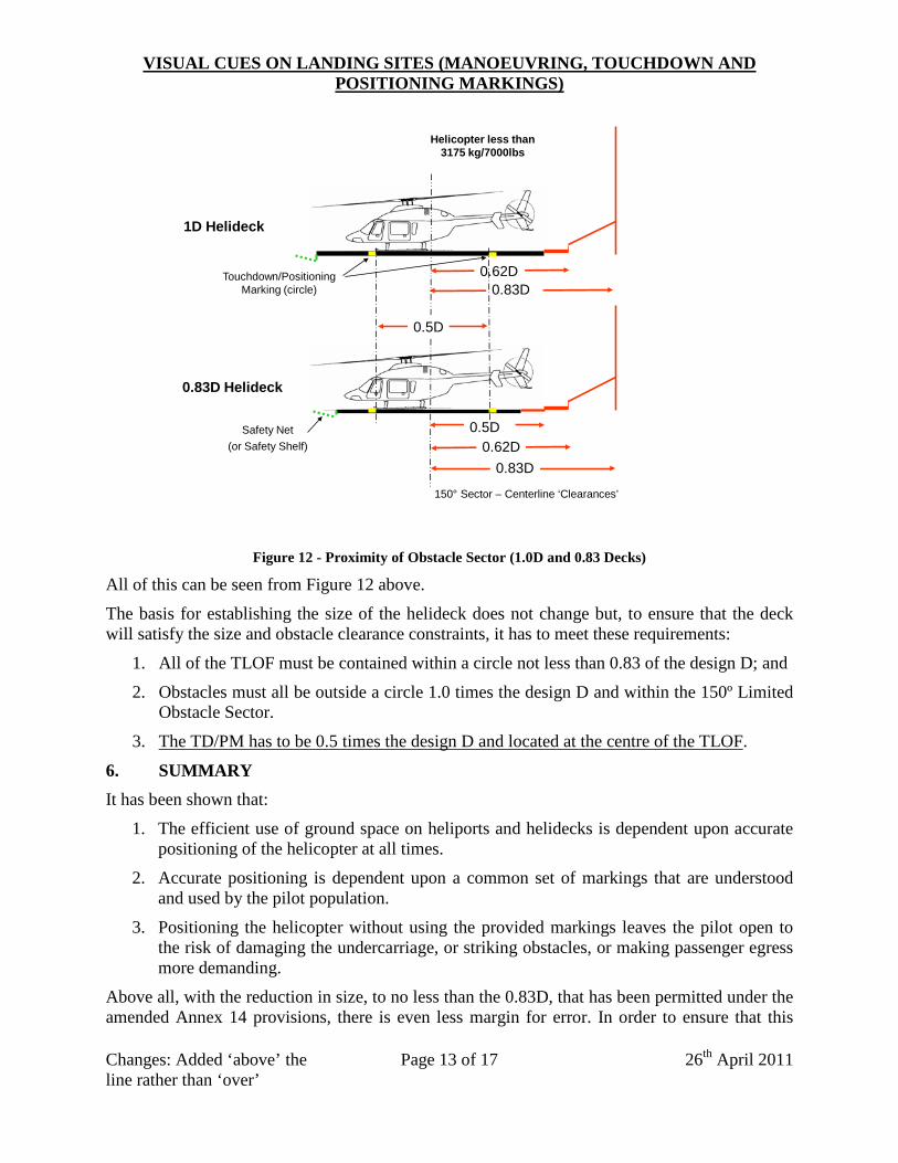
1D Helideck
0.83D Helideck
0.62D0.83D
150° Sector – Centerline ‘Clearances’
Helicopter less than 3175 kg/7000lbs
0.83D0.62D
0.5D
Touchdown/Positioning Marking (circle)
0.5D
Safety Net (or Safety Shelf)
Figure 12 - Proximity of Obstacle Sector (1.0D and 0.83 Decks)
All of this can be seen from Figure 12 above.
The basis for establishing the size of the helideck does not change but, to ensure that the deck will satisfy the size and obstacle clearance constraints, it has to meet these requirements:
1. All of the TLOF must be contained within a circle not less than 0.83 of the design D; and
2. Obstacles must all be outside a circle 1.0 times the design D and within the 150º Limited Obstacle Sector.
3. The TD/PM has to be 0.5 times the design D and located at the centre of the TLOF.
6. SUMMARY It has been shown that:
1. The efficient use of ground space on heliports and helidecks is dependent upon accurate positioning of the helicopter at all times.
2. Accurate positioning is dependent upon a common set of markings that are understood and used by the pilot population.
3. Positioning the helicopter without using the provided markings leaves the pilot open to the risk of damaging the undercarriage, or striking obstacles, or making passenger egress more demanding.
Above all, with the reduction in size, to no less than the 0.83D, that has been permitted under the amended Annex 14 provisions, there is even less margin for error. In order to ensure that this
VISUAL CUES ON LANDING SITES (MANOEUVRING, TOUCHDOWN AND POSITIONING MARKINGS)
Changes: Added ‘above’ the line rather than ‘over’
Page 14 of 17
26th April 2011
reduction does not lead to an increase in accidents, it is important that operators understand their responsibility for ensuring that the appropriate markings are in place but, most of all, pilots understand and take advantage of the safety that is assured when they correctly use the visual cues/markings and adhere to the principles that are set out in the ICAO Standards and in CAP 437.
Appendix A Obstacle-Free Areas – Below Landing Area Level
Changes: Added ‘above’ the line rather than ‘over’
Page 15 of 17
26th April 2011
Appendix B Diagram of Helideck Obstacle Limitation Sectors (1D Deck)
Changes: Added ‘above’ the line rather than ‘over’
Page 16 of 17
26th April 2011
Appendix C Diagram of Helideck Obstacle Limitation Sectors (0.83D Deck)
Changes: Added ‘above’ the line rather than ‘over’