312
A Visual Programming Environment for Functional Languages Joel Kelso This thesis is presented for the degree of Doctor of Philosophy of Murdoch University 2002
| Date post: | 05-Apr-2018 |
| Category: |
Documents |
| Upload: | blancolioni |
| View: | 218 times |
| Download: | 0 times |

7/31/2019 Visual Fp Environment
http://slidepdf.com/reader/full/visual-fp-environment 1/312
A Visual Programming Environment for Functional
Languages
Joel Kelso
This thesis is presented for the degree of Doctor of Philosophy of
Murdoch University
2002

7/31/2019 Visual Fp Environment
http://slidepdf.com/reader/full/visual-fp-environment 2/312
I declare that this thesis is my own account of my research and contains as
its main content work which has not previously been submitted for a degree
at any tertiary education institution.
Joel Kelso
ii

7/31/2019 Visual Fp Environment
http://slidepdf.com/reader/full/visual-fp-environment 3/312
Abstract
The purported advantages of Visual Programming, as applied to generalpurpose programming languages, have remained largely unfulfilled. The essence of this thesis is that functional programming languages have at least one natural visualrepresentation, and that a useful programming environment can be based upon thisrepresentation.
This thesis describes the implementation of a Visual Functional Programming
Environment (VFPE). The programming environment has several significantfeatures.
• The environment includes a program editor that is inherently
visual and interactive: syntactic program components have avisual representation and are assembled via a graphical interface.
• The program editor incorporates a static analysis system that
tracks types for the whole program, making it impossible toconstruct syntactically incorrect or type-incorrect programs. Typeinformation is continually and explicitly available to theprogrammer.
• The environment implements an implicitly typed higher-order
purely functional language without conforming exactly to anyparticular language with respect to syntactic structures orreduction semantics.
• Programs can be output as source code for an existing functional
language.
• The visual representation allows for continued experimentation
with new syntactic features. Some currently included features arealgebraic data types, pattern matching, and guarded expressions.
• The environment includes a visual interpreter which allows any
expression to be reduced in source form, with a choice of reduction behaviors.
Please note that this thesis was written to be read in conjunction with a set of animated examples. The examples should be present on some form of digital mediaaccompanying this thesis: at the points indicated in the thesis text, the reader shouldview the associated example.
iii

7/31/2019 Visual Fp Environment
http://slidepdf.com/reader/full/visual-fp-environment 4/312
Contents
1.Introduction..................................................................................................... 1
1.1 Software and Programming........................................................................ 1
1.2 Programming Languages and Computational Models.............................. 5
1.3 Functional Programming ..........................................................................11
1.4 Visual Programming................................................................................. 17
1.5 Thesis......................................................................................................... 26
2.Related Work.................................................................................................28
2.1 Static Visual Program Representations....................................................28
2.2 Textual Functional Languages..................................................................32
2.3 Language Aware Editors...........................................................................38
2.4 Dataflow Programming.............................................................................44
2.5 Visual Functional Languages................................................................... 50
2.6 Functional Language Debugging and Profiling.......................................57
3.Visual Syntax for Functional Programs.................................................... 67
3.1 Language Grammars and Syntax Trees................................................... 68
3.2 Dynamic Layout........................................................................................77
3.3 Box Representations..................................................................................78
3.4 Graphs Representations, Identifiers and Anonymous Definitions..........81
3.5 Comments..................................................................................................89
3.6 Node Faces and Icons................................................................................91
3.7 Syntactic Redundancy...............................................................................93
3.8 Type representation...................................................................................95
4.VFPE Visual Syntax..................................................................................... 98
4.1 Syntactic Classes....................................................................................... 98
4.1.1 Syntax.................................................................................................100
iv

7/31/2019 Visual Fp Environment
http://slidepdf.com/reader/full/visual-fp-environment 5/312
4.1.2 Values.................................................................................................100
4.1.3 Abstractions....................................................................................... 101
4.1.4 Bindings............................................................................................. 103
4.1.5 Application Expressions....................................................................104
4.2 Syntax Node Flavours.............................................................................105
4.2.1 Placeholder.........................................................................................105
4.2.2 Literal................................................................................................. 108
4.2.3 Variable.............................................................................................. 109
4.2.4 Application.........................................................................................110
4.2.5 Lambda...............................................................................................114
4.2.6 Let.......................................................................................................116
4.2.7 Datatype............................................................................................. 120
4.2.8 Prelude................................................................................................123
4.2.9 Conditional.........................................................................................124
4.2.10 Pattern-Set........................................................................................125
4.2.11 Guard-Set......................................................................................... 128
4.2.12 List....................................................................................................130
4.2.13 Variable Binding..............................................................................132
4.2.14 Literal Binding.................................................................................134
4.2.15 Constructor Binding........................................................................ 135
4.2.16 Datatype Constructor Binding........................................................ 137
4.2.17 Prelude Binding............................................................................... 137
5.Editing Operations......................................................................................139
5.1 Browsing..................................................................................................141
5.1.1 Node Information Windows..............................................................142
5.1.2 Navigation..........................................................................................144
v

7/31/2019 Visual Fp Environment
http://slidepdf.com/reader/full/visual-fp-environment 6/312
5.1.3 Navigational Modifications...............................................................147
5.2 Drag and Drop Editing............................................................................150
5.3 Drag Sources............................................................................................152
5.3.1 Binding Nodes................................................................................... 152
5.3.2 The Pallet: Prelude Functions........................................................... 156
5.3.3 The Pallet: Basic Syntax....................................................................159
5.3.4 Literal Field........................................................................................160
5.3.5 Cut and Copy..................................................................................... 161
5.4 Drag-and-Drop Operations (Drag Targets)............................................162
5.4.1 Constructing Values.......................................................................... 164
5.4.2 Constructing Patterns.........................................................................165
5.4.3 Let on Value Expression................................................................... 166
5.4.4 Pattern-Set on Lambda...................................................................... 167
5.4.5 Value Expression on Delete, Save or Write Textual Code..............168
5.5 Context Sensitive Editing Controls........................................................ 170
5.5.1 Syntax (Common)..............................................................................171
5.5.2 Bindings............................................................................................. 171
5.5.3 Value...................................................................................................172
5.5.4 Lambda and Apply............................................................................ 173
5.5.5 “Now-Showing” Item Controls.........................................................173
5.5.6 Let.......................................................................................................174
5.6 Incremental Syntax Checking.................................................................176
5.7 Editing Operation Summary...................................................................184
5.8 Editor Operation Statistics......................................................................185
5.9 Workspaces..............................................................................................187
6.External Forms............................................................................................193
vi

7/31/2019 Visual Fp Environment
http://slidepdf.com/reader/full/visual-fp-environment 7/312
6.1 Serialised Functional Expressions..........................................................193
6.2 Haskell Code Fragments.........................................................................199
7.Type Checking.............................................................................................201
7.1 The VFPE Type System..........................................................................201
7.2 Visible Types...........................................................................................203
7.3 Incremental Type Checking....................................................................206
7.4 Type Maintenance...................................................................................208
7.4.1 Instantiation (Node creation).............................................................209
7.4.2 Placeholder Update and Binding Update..........................................210
7.4.3 Let Bindings, Empty Let, Datatypes.................................................214
7.4.4 Unoptimised Operations....................................................................215
7.4.5 Type Checking During Execution.................................................... 216
7.5 Empirical Evaluation of R...................................................................... 218
7.6 Type Declarations....................................................................................220
8.Reduction..................................................................................................... 222
8.1 Source-Level Interpretation.................................................................... 223
8.2 Incremental Execution............................................................................ 231
8.3 Reduction Algorithm...............................................................................236
8.3.1 Reduction Algorithm Annotation..................................................... 240
8.4 Interpreter Controls................................................................................. 249
9.Interpreter Examples................................................................................. 251
9.1 Reduction Examples................................................................................251
9.2 Algorithm Animation..............................................................................252
9.3 Profiling................................................................................................... 253
9.4 Simulating Parallel Reduction................................................................253
10.Conclusions and Further Research Directions.....................................256
vii

7/31/2019 Visual Fp Environment
http://slidepdf.com/reader/full/visual-fp-environment 8/312
10.1 Novel Contributions..............................................................................256
10.2 Future Research Directions...................................................................258
10.2.1 Measurement of Visual Programming Environment Operation.. .258
10.2.2 “Visual Haskell”.............................................................................. 259
10.2.3 Functional Program Transformation Tool......................................262
10.2.4 Incremental Type Inference............................................................ 265
11.Appendices.................................................................................................268
11.1 Appendix: Parallel Tuple Syntax Flavour............................................268
11.2 Appendix: Program Construction Measurement Data........................270
11.3 Appendix: Outline of an experiment for evaluating the effectiveness of
Visual Programming with the VFPE........................................................................ 273
11.3.1 Preparation....................................................................................... 274
11.3.2 Group Selection............................................................................... 276
11.3.3 Measurement....................................................................................277
11.4 Appendix: Cognitive Dimensions Usability Analysis of the VFPE...279
11.4.1 Analysis............................................................................................279
11.4.2 Conclusions......................................................................................290
12.References.................................................................................................. 292
viii

7/31/2019 Visual Fp Environment
http://slidepdf.com/reader/full/visual-fp-environment 9/312
Acknowledgements
The author would like to thank Professor Geoff Roy for his supervision andguidance, and for his unflagging patience. He would also like to thank Dr TonyField for his comments on the project and suggestions on the interpreterenvironment.
ix

7/31/2019 Visual Fp Environment
http://slidepdf.com/reader/full/visual-fp-environment 10/312

7/31/2019 Visual Fp Environment
http://slidepdf.com/reader/full/visual-fp-environment 11/312
1. Introduction
Computer software is a complex and important part of the modern world. As
computing hardware shrinks in size and cost, computers are being used in an ever-
widening panoply of devices and situations. Every new device designed, and every
new computational problem posed, demands its own software. Given that the
importance of software is only likely to increase, exploration into new methods of
constructing software is important. This introductory chapter explains the
motivation for this thesis, beginning with the importance of software and
programming environments in general, and moving on to the reasons for the focus on
functional languages and visual programming.
1.1 Software and Programming
What, in essence, is software ? Software is the intermediary between the
problem specifications and designs that exist in the minds of software engineers, and
1
x x
x
mental model of
computation
specification of
computation
embodiment of
computation
authorship, understanding
compilation, interpretation,
execution
Two facets of software
Figure 1

7/31/2019 Visual Fp Environment
http://slidepdf.com/reader/full/visual-fp-environment 12/312
the computing machinery that will be used to carry out a computation to solve the
problem. In short, software is a specification of a computation.
A computation can take many different forms. It can have essentially no
input (for example, a program to list prime numbers, or enumerate all distinct graphs
conforming to a particular constraint), can operate on finite input (e.g. a compiler
compiling a set of source files), or can operate on a continuous stream of input (e.g. a
stream of database transactions). Computations can produce output data in any
number of forms. Output can be as simple as a true/false answer, or as complex as
list of motor instructions for controlling a robot arm; it can be as small as a single bit,
or as large as the terabytes of frames that comprise an animated movie.
Specifications can take different forms, such as pure (mathematical)
functions, procedural algorithms, or state machine descriptions. The essential feature
common to all computational specifications is that they stipulate what output can
(and in the case of a deterministic computation, must) be produced for each possible
input given the computation’s state; and what effect the input has on the
computation’s state. Software is exactly these specifications, encoded.
One facet of a body of software is the final operational product of the
software engineering process: the executable pattern of data running on a computer,
solving some computational problem. The final executables are specified exactly by,
and are derived automatically from, the software’s source code. The source code can
therefore be considered another facet of the same abstract software. In fact, with the
use of interpreted languages and virtual machines, this relationship between source
code and executable can be more than philosophical.
Clearly, if it is to run at all, software must be in a form intelligible to the
target computer system (or commonly, able to be automatically translated into such a
2

7/31/2019 Visual Fp Environment
http://slidepdf.com/reader/full/visual-fp-environment 13/312
form). The behavior and performance of executable code on different computer
architectures, and the design of the architectures themselves, are fields of software
engineering research. Equally, if not more importantly, software must be intelligible
to human beings.
From the human point of view, software consists of the source code for
programs and libraries, written in various programming languages. It also consists of
supporting documentation, which records the problem specifications, designs and
notes created during the engineering process.
The process of producing software has recognisable phases: specification is
the setting down of the intent and requirements of the software in greater or lesser
detail, design is the planning of the overall structure of the software that will fulfill
the specifications, implementation is the process of writing and testing the source
code that actualises the design, and maintenance is the term applied to activity after
the implementation of a product is complete: maintenance involves fixing bugs and
modifying the software to meet changing requirements. Whether a strict “waterfall”
model, where specification, design, implementation and maintenance ideally follow
in turn, or a rapid prototyping approach, where the phases are more finely
interleaved, is adopted, each of the phases is still recognisably present.
One possible classification of the tasks performed by programmers is into
construction, debugging and modification. Construction, the creation of source code
ex nihilo (as it were), is the most commonly thought-of programming activity.
Starting with an abstract notion of the problem to be solved, the programmer writes
down instructions which, when translated, placed in the correct context and fed the
appropriate data, will solve the computational problem.
3

7/31/2019 Visual Fp Environment
http://slidepdf.com/reader/full/visual-fp-environment 14/312
Debugging is the correction of faults. A bug occurs when the outcome of the
software’s execution is at odds with the programmer’s intention. In debugging, the
task is to find and correct whatever is causing the divergence, whether it is a
misunderstanding of the computational problem, a misconceived or incorrectly
executed solution, or (rarely) a fault in the computing machine on which it is being
executed.
Code construction and correction is not the only, or even the most important,
programming activity. Modification of existing code takes place for a number of
reasons, such as to change the code’s performance, to generalise the solution it offers
to a larger set of problems, or to reproduce the same functionality in a differing
underlying environment (“porting”).
Obviously, software must be intelligible to its creator (in some cases, perhaps
only momentarily). More subtly, and these are some of the clear results of the
relatively short history of software engineering, software should be intelligible to
people other than its creator , at times other than its creation, and for purposes other
than its original intent . Intelligibility is important because software engineers make
mistakes (at all levels of the process), because the circumstances that provoke the
creation of a piece of software change over time, and because software is a repository
of solutions to computational problems that can be re-used, or at least ransacked for
ideas. The maintainability of a body of software depends on how intelligible it
remains after its construction.
The focus of this thesis will be programming; defined as the creation and
manipulation of source code. In terms of the software engineering process, this
occurs at the lower level design, the maintenance, and of course the implementation
phases. Note that this focus is not intended to belittle the importance of the vital
4

7/31/2019 Visual Fp Environment
http://slidepdf.com/reader/full/visual-fp-environment 15/312
specification and design phases: it is recognised that there are large problems with
the practice of software engineering in these phases (see e.g. [Brooks 75]). Nor is it
suggested that these activities could not benefit from their own visualisation tools.
The point is rather that one has to focus somewhere, and programming is a distinct
and important activity that could benefit from visualisation tools. With increasing
levels of programming language abstraction, the boundary between implementation,
specification and design is beginning to blur in any case.
A major factor in the effectiveness of programmers is the languages and
programming environments with which they work.
Programming languages are sometimes described as being more or less
powerful. This refers to the degree to which small amounts of code can be made to
solve large problems. Expressive power is a measure of how smaller problem
solutions (existing as library features, or program parts which solve sub-problems)
can be succinctly combined in useful ways. A major thrust of programming
language research is the development of powerful, comprehensible programming
languages and their associated programming tools.
In addition to the language itself, the surrounding apparatus used to enter,
browse, edit and possibly execute the program has a bearing on the effectiveness of
the programmer. Regardless of the skill of the programmer and how well
constructed a language is, tools are needed that allow programmers to express their
intentions as effortlessly as possible.
1.2 Programming Languages and Computational Models
Programming involves the creation of a pattern of data (a program) which,
when fed into some computing machine, solves a particular computation problem.
5

7/31/2019 Visual Fp Environment
http://slidepdf.com/reader/full/visual-fp-environment 16/312
The form of the program depends on the nature of the machine being programmed.
At this point in history, the machine physically performing a computation is likely to
be a microprocessor based machine with the Von Neumann architecture: a central
processing unit with several hundred simple arithmetical and logical instructions
which operate on a large array of memory words, with the executing program being
fetched (essentially one instruction at a time) from the same memory, along with
various other attached input and output devices.
In fact from a programming point of view, for a vast majority of work, we are
instructing no such machine, and haven’t been for decades. With any kind of
programming above the level of raw machine code, we actually program a virtual
machine defined by the programming language. The program is translated and/or
interpreted by a conceptual tower of virtual machines, ultimately grounded in the
physics of the hardware of some real computer. There are at least three motivations
for this drive to program at “higher” levels of abstraction.
The first motivation (also historically the first) is that of programmer
efficiency. The first electronic computers were so expensive, and the restrictions on
the size of programs so severe that it was well worth dedicating programmer time to
crafting each instruction “by hand”. With increasing machine capacity (and
plummeting cost, relative to the cost of the programmer’s time) came a progression
of tools for automating the programming process: assemblers, compilers,
interpreters, static type checking, automated storage management and so forth. The
intention of these tools was originally to serve as labour saving devices, to avoid
tedious duplication of effort, but other benefits followed.
A second motivation for the use of languages with higher levels of
abstraction is in order to hide the details of the machines at lower levels. By defining
6

7/31/2019 Visual Fp Environment
http://slidepdf.com/reader/full/visual-fp-environment 17/312
an abstract machine and re-implementing a relatively small amount of low-level
code, a large amount of code can be re-used for a whole set of different lower level
machines. An enormously successful example of this is the C/UNIX “abstract
machine”. A more recent example, and one deliberately motivated by the attempt to
hide machine dependencies (the machines in this case being mutually incompatible
operating systems), is the Java language/virtual machine [Goslin 00].
A third motivation is the attempt to move the programming effort away from
the domain of the capabilities of the target machine and into a domain more useful
for stating problem solutions. The most successful deliberate moves in this direction
have been the development of object-oriented programming (where the rationale has
been to support the modeling of conceptual objects in the problem domain) and the
declarative programming paradigms of logic and functional programming. The last
of these, where computations are expressed in the form of mathematical functions, is
the particular focus of this thesis. This third motivation is partially an extension of
the first (the increase in programmer productivity), but the goal is approached by
attempting to equip the programming with new, more powerful tools, rather than to
simply automate the tasks carried out by the programmer.
Upon reflection, it seems obvious that once computing capacity became
cheaper than the time of the programmers instructing the machines, efforts to make
programmers more productive would become cost-effective and commercially
inevitable. Using (relatively cheap) computational power to implement
programming languages that enhance programmer efficiency was an obvious step.
Sometimes new programming languages and features have developed in an
evolutionary manner, with later languages adding features to earlier languages in an
7

7/31/2019 Visual Fp Environment
http://slidepdf.com/reader/full/visual-fp-environment 18/312
incremental fashion. The positive side of this evolution is that the familiarity of
programmers with the language is maintained.
The negative side of evolutionary language development is that as new
features are added, it becomes increasingly difficult to preserve a simple
understanding of the translation (and/or interpretation) of programs, and to easily and
exactly predict their behaviour. If compatibility with earlier languages is kept,
finding new niches in the language grammar, and ensuring that the new features
interact with the older features in an intuitive way, becomes increasingly difficult.
The C++ language [Strous 85], an extension to (and superset of) the
ubiquitous C language, is an illustrative example, demonstrating both sides of the
coin of evolutionary language development. Providing a new set of features while
drawing on the large number of programmers experienced with the C languages, it
has become extremely widely used. It is also widely regarded as a requiring extreme
care when making full use of its many features, and stands at the end of its particular
evolutionary line.
If the evolutionary approach is taken but compatibility with earlier languages
is deliberately discarded, then care must be taken to make sure that the differences in
behavior between languages are understood (the “Java for C programmers” sections
that appear at the beginning of many Java programming manuals illustrate this
point).
In contrast to evolutionary language development, some new languages arise
from deliberate attempts to use a new underlying computational model, rather than
extending an older one. The disadvantages of this approach are that a new,
unfamiliar language (and sometimes new modes of thought and problem solving)
8

7/31/2019 Visual Fp Environment
http://slidepdf.com/reader/full/visual-fp-environment 19/312
must be learned by programmers; and that an efficient translation path to existing
languages or hardware must be designed.
The potential advantages of the revolutionary, rather than evolutionary,
approach to language design are great. Solutions to problems can be expressed in a
way that is suited to the understanding of the programmer, who is after all the
complex and expensive part of the process. The high level of abstraction means that
the goal of attaining a solution by simply being able to precisely state the problem
can be approached.
All programming languages define an abstract computing machine on which
their programs run. This fact can be looked at from another angle and turned into a
question: what sort of abstract machines can be programmed to perform useful
computations, and to what sort of programming languages do they give rise ?
There is an application here of a fundamental result (arguably the
fundamental result) of computer science: the equivalence of general purpose
computing machines. Starting with Turing’s result about a Universal Turing
Machine that can emulate any other Turing Machine, the exact equivalence in
problem solving power of various abstract computing models has been proven. Early
results included the equivalence of machines devised independently by Turing’s
contemporaries, such as Emil Post’s machine, and the λ-calculus by Alonzo Church.
In the following decades many more computational systems have been proven
equivalent to the Turing Machine (and hence to all the others). Examples of
computational models include problems in tessellating the plane with connecting
tiles [Berger 66] [Wang 63], systems of certain kinds of integer equations
9

7/31/2019 Visual Fp Environment
http://slidepdf.com/reader/full/visual-fp-environment 20/312
(Diophantine equations) [Matiya 70], and various cellular automata [Neuman 66].
Programs expressed in any one of these architectures can be transformed into a
program for any of the others.1
Now, all of these machines are in fact extremely tedious to program, and are
probably not useful for most practical tasks. This is not surprising, since they were
contrived for the reason that they are simple to describe mathematically, not for the
convenience of programmers. The point is that there is an infinite variety of
computing machines, all capable of performing any computation that any of the
others can. Instead of programming a machine that is based on physical hardware
extended in a piecemeal fashion, why not choose an abstract machine according to
some deliberate goals ?
A useful feature of an abstract machine is the existence of an efficient
translation path to physical hardware. While this is important if we ’t want to
maximise the size of problems we can tackle, its importance can be overstated.
Hardware architecture is a moving target, and today’s carefully tuned programming
model may turn out to be an awkward fit to the next generation of powerful
processors anyway.2
1 A literal example is the outline for a LISP machine “running on” a set of Diophantine
equations has been given [Chaiti 93] i.e. an outline for translating an arbitrary program in a small
subset of LISP into a set of Diophantine equations, the solution of which yields the result of the LISP
program, the lack of solution indicating non-termination of the program.2 This is in essence what has happened with current procedural languages and parallel
computing hardware. The most successful (from a commercial standpoint) improvements in
processor performance have all been completely hidden from the programming model, for example
Intel’s Pentium 4 processor is effectively functionally identical to the i80386, more than a decade old.
Even this success has reached it’s limit: Intel’s succeeding generation of processors (the “Itanium”)
executes explicitly parallel instruction streams. To utilize these processors, the level at which the
programming model is screened from the hardware will have to move up a level, from the binaries
executed by the processor to the compiler that generates the binaries.
10

7/31/2019 Visual Fp Environment
http://slidepdf.com/reader/full/visual-fp-environment 21/312
In the medium term, virtual machines that facilitate clear understanding of
problem domains and computational solutions are a good idea. Where the bottleneck
in effective deployment of computers is the construction and maintenance of
software, this will remain true.3
1.3 Functional Programming
The functional programming paradigm is an example of a programming
model chosen with regard to the expression of solutions to computational problems
rather than for having programs translate simply to stock hardware.
In functional programs, computations are specified by defining and applying
functions. “Functions” here refers to the concept of a mathematical function.
Mathematical functions are mappings between elements of one set (the domain) and
another (the codomain); the mapping can be many-to-one, but not one-to-many.
The programming of massively parallel machines, which have the potential to far outstrip
the performance of current machines, requires different programming language and compiler
technology, and has not been taken up by the mass market.
3 While the world’s population looks like it probably will not double again more than once
[Lutz 01], Moore’s observation that the power of computing machines doubles roughly every two
years, looks set to last for at least another decade or so. Even if developing nations experience great
increases in literacy and education, and the software industry becomes a dominant force in the global
economy, the cost of computing power is still likely to continue to fall compared to the cost of
employing programmers.
The long-term picture may be different again. There are fundamental theoretical limits onthe power of computational devices [Lloyd 00], and it is likely that practical engineering limits will
be met before these are reached. At some point, the current exponential increase in the power of
computers must level out. By this time, it is likely that many of the demands for computing power
will have been extensively studied, and good solutions will have been found. It may then be the case
that programmers may return to low-level programming to gain the most from the hardware.
Candidates for these computationally intensive problems include all kinds of physical modeling (such
as quantum lattice models for high-energy physics, global climate models etc.), detailed extensive
shared virtual environments, artificial intelligences, and artificial life simulations.
11

7/31/2019 Visual Fp Environment
http://slidepdf.com/reader/full/visual-fp-environment 22/312
The computational model for functional programming languages is the
lambda calculus. The λ-calculus was originally developed (by Alonso Church in the
1930’s [Church 41] [Curry 58]) as a means of describing the properties of
mathematical functions in a purely syntactic way. A λ-calculus “program” (a λ-
expression) is a tree-structured syntactic expression. The calculus defines reduction
rules that transform the λ-expression at certain sites (called redexes); evaluation of
the program proceeds by repeated application of the reduction rules. Some
expressions and reduction sequences give rise to an unlimited number of redexes
(these are non-terminating computations), while others terminate in a normal form.
The λ-calculus bears roughly the same relationship to functional
programming languages as the Turing Machine4 does to procedural programming
languages, although the distance between the functional languages and their
underlying theoretical basis is a good deal smaller than for procedural languages.
Like a Turing Machine, the pure λ-calculus operates on symbols in a semantically
empty way. It can be shown, however, that arbitrary structures and computations can
be encoded as λ-expressions.
Functional languages are essentially extended versions of the λ-calculus, with
specified algorithm for selecting redexes for reduction. The λ-calculus can be
extended to include additional reduction rules (for performing arithmetic and list
manipulation, for example) while retaining its important computational properties.
Much has been written on the rationale behind the development and use of
functional languages (e.g. [Hughes 89], [Hudak 00]). This section will outline some
4 The Random Access Machine (RAM), a variant of the Turing Machine, is a better model
for contemporary hardware, and thus for procedural languages.
12

7/31/2019 Visual Fp Environment
http://slidepdf.com/reader/full/visual-fp-environment 23/312
of the properties of the functional language computational model and the
concomitant advantages offered to programmers and language implementers.
Mathematical functions treated as a computational element have a very
important property: the output of the element is determined exactly and only by the
input values. In other words, they are stateless, and for a particular set of input
values will always return the same result. When applied to functional programs, this
means that the same program text appearing in the same scope will always compute
the same result: this property is referred to as referential transparency.
Compare this to a procedure in an imperative programming language
(procedures are sometimes also called functions, since they are often written to
compute a function). The input of a procedure appears to be the parameters supplied
to the procedure, and the output the return value. However, the return value can
depend on the values of any data in the procedure’s scope (including global variables
and reference parameters, for example); and may in turn modify this data. When
treating a procedure as a computing element, all this data must be considered as part
the input and output.
This can cause problems in programming. The expression notation used in
nearly all programming languages (including imperative ones) has its origins in
mathematical notation, and programmers may come to believe, intentionally or not,
that the procedures appearing in expressions will behave in a referentially transparent
way. When writing or reading procedures, symbols referring to a procedure’s
arguments usually look identical to symbols referring to in-scope data. This is
deliberate and generally desirable, since both sorts of references can be used in the
same way in the body of a procedure. Unfortunately, it can make locating all the
procedure’s inputs and outputs difficult. Worse, just because a procedure contains
13

7/31/2019 Visual Fp Environment
http://slidepdf.com/reader/full/visual-fp-environment 24/312
no global data references it does not ensure the procedure is referentially transparent:
it may call some other procedure that does contain such references.
Apart from making programs easier to read and more predictable, referential
transparency has other advantages. Equational reasoning about programs becomes
possible, allowing various sorts of properties for programs to be proven.
Applications of such proofs include proofs of program equivalence, some sorts of
correctness and termination proofs, program synthesis and, most importantly, many
types of optimisation.
Functional languages are syntactically and semantically simple. Compared to
imperative languages, they have fewer basic mechanisms for aggregating smaller
program parts into larger ones. For instance, procedural languages require syntactic
structures for selection (conditional statements), iteration (loops), sequence, and non-
local exits (return and break statements) in addition to procedure calls. In a purely
functional language, selection can be handled by a library function that is not
syntactically distinguished from other functions (built-in or user-defined); iterative
behavior is achieved by writing tail-recursive functions; there is no explicit
sequencing of operations, and no non-local exits.
An inherent feature of the λ-calculus, which can be extended to functional
languages, is the existence of higher-order functions. With higher-order languages,
abstracted computations are treated as first-class citizens and can be manipulated in
the same way as other data types, meaning that they can be passed as arguments to
other computations and stored in data structures for delayed use. It is difficult to
overestimate the usefulness of this programming language feature; its use allows and
14

7/31/2019 Visual Fp Environment
http://slidepdf.com/reader/full/visual-fp-environment 25/312
encourages a high degree of abstraction and modularity in code.5 The presence of
functions as higher-order, referentially transparent building blocks makes the
functional programming model an extremely powerful “glue” for abstracting and re-
using common patterns of problem solving.
The Church-Rosser property (a confluence property) states that the order of
execution of parts of a program has no effect on the result of the program. This
agrees with the familiar convention for mathematical expressions and equations,
where it is taken for granted that the order of evaluation of an expression has no
effect on its value.
The confluence property gives functional languages great potential for
concurrency that is entirely absent from the inherently sequential Turing Machine.
Each redex in a λ-expression can potentially be reduced in parallel without changing
the final result reached. The challenge in writing parallel functional programs is not
in dividing the computation into concurrent parts (i.e. parts that will be executed
simultaneously) that will be guaranteed to give the same result as an equivalent
sequential program; rather, it is in choosing how to allocate processing resources to
redexes in order to maximise utilisation of processing resources and minimise
communication overhead.
Another important property is the standardisation property which states that
there is a reduction order (a way of choosing the next redex at each step in the
5 Its usefulness can be seen by the fact that higher-order behavior shows itself in some form
or another in many languages across language paradigms, although often in an impoverished form. C
and Pascal allow the use of function pointers, although any sort of closures need to be constructed by
hand. Object-oriented languages allow the passing of objects whose methods can be used as higher-
order code (a usually syntactically cumbersome technique). Functional languages (LISP in
particular) were the original motivators in the uniform treatment of functions and data, and it is in
functional languages that higher-order functions really shine.
15

7/31/2019 Visual Fp Environment
http://slidepdf.com/reader/full/visual-fp-environment 26/312
reduction of a λ-expression) that ensures that the reduction sequence will terminate,
provided that the expression has a normal form. This means that in functional
languages that employ so-called normal-order reduction (NOR), computation is
completely demand-driven. This means that only computations that are necessary
for the completion of the program are ever performed, and that programmers are free
to define potentially infinite data structures and computations without worrying
about the order in which they will be performed, or that the program will run away
and compute things needlessly. Constructing potentially infinite structures may
sound like an outlandish thing to want to do, but there are computations that are
much more clearly specified with so called “lazy” evaluation.
Due to the abstract nature of their underlying computational model,
functional programs come much closer to allowing programmers to specify what
computation is to be performed, rather than having to become involved in the
minutiae of how the computation is to be performed. This is the distinction between
the so called declarative and imperative programming paradigms. Functional
programs tend to be more compact, modular and comprehensible than their
imperative counterparts.
Functional languages have been successfully used for a wide variety of
software projects at all scales. A more-or-less random sampling might include the
MACSYMA symbolic mathematics system [Rand 84]; Erlang, Ericsson’s concurrent
functional programming language which has been used to prototype and implement
large telephone switching systems [Armstr 90] [Armstr 96]; the LOLITA natural
language understanding system [Smith 94]; and the widely deployed Yahoo web
shopping engine written in Lisp [Graham 01].
16

7/31/2019 Visual Fp Environment
http://slidepdf.com/reader/full/visual-fp-environment 27/312
As with most implementations of high-level programming languages,
functional languages have had the reputation of having relatively poor run-time
performance (due in a large measure to experiences with early interpreted
implementations). With sophisticated compilation and optimisation techniques
(many of which are feasible due to the program analysis and transformation
techniques possible with functional languages), it has been shown that software
implemented in functional languages can equal or exceed the performance of
imperative languages.6 The potential for the automated or semi-automated
parallelisation of functional programs is also beginning to be realised.
The paragraphs above repeat some of the commonly expounded software
engineering benefits of functional programming languages. More interestingly, from
the point of view of this thesis, the functional programming model may have
advantages (over other computational models) when it comes to the pictorial
representation of programs and computations. This hypothesis is a major focus of
this thesis, and is explored beginning in chapter 3.
1.4 Visual Programming
Programs written in the programming languages in common use today are
encoded in textual form. As pointed out previously, as computing power becomes
cheaper relative to the fixed (or at least more slowly changing) cost of programmer
time, it becomes more worthwhile to devote computing cycles to making the
programmer more productive.
One such transition occurred in the 1950s with the progression from front-
panel and punched tape interaction to teletype based interaction. The choice of the
6 [Cann 92] for instance compares the performance of a functional language (Sisal) with
optimising compiler with that of Fortran.
17

7/31/2019 Visual Fp Environment
http://slidepdf.com/reader/full/visual-fp-environment 28/312
line-based textual interface was an obvious one given that there was already a
technology for converting human readable and writeable symbols into electrical
signals and vice-versa: the electromechanical teletype. The particular alphabet of
symbols (the ASCII) and the layout conventions (a vertical list of variable length
horizontal lines of characters) used almost universally for programming languages
has remained essentially unchanged since this time: our programs are actually
telegrams (for an interesting point of view on textual interface culture, see [Stephe
99]).
The main idea behind Visual Programming is that using pictorial
representations for programs (and manipulating them by gesturing with a pointing
device) is better than the textual status-quo, which involves reading and typing. In
this section the concept of Visual Programming in general is discussed. This is
followed by a digression on the subject of the dominance of textual programming,
and some words on the motivation for the combination of visual and functional
programming.
One immediate attraction of Visual Programming is the opportunity to apply
the Graphical User Interface (GUI) techniques that have been so successful in other
applications to software development. The importance of GUI techniques can be
gauged by the fact that in the space of a decade they almost totally supplanted the
textual command-line interface, and are now the standard method of interaction
expected by nearly all computer users. The difference between GUIs and command-
line interfaces is often expressed as being the difference between a “point and click”
interface as opposed to a “remember and type” interface. Most users find the
prospect of learning the (often arcane) names and syntax of textual commands
daunting. For these users the tasks required by a GUI interface, such as pointing,
18

7/31/2019 Visual Fp Environment
http://slidepdf.com/reader/full/visual-fp-environment 29/312
clicking and dragging, are a more natural and intuitive method of interacting with
computers. A software development environment could benefit from GUI interface
advantages in the same way as any other application, even if only due to the
familiarity of the metaphors and gadgets used.
Beyond this rather shallow but practical attraction, there is a deeper allure:
the prospect of representing the structure of programs in a fundamentally different
way. There is the prospect of using (at least one of) the extra dimensions of colour,
iconography, motion, sculpture, or two- or three-dimensional diagrams to represent
programs. The extra dimensions could be used either to represent programs in new
computational models, or to enhance the representation of programs in existing
languages. The variety of ways in which the extra expressive dimensions could be
used is very large indeed: a few of the more obvious are discussed below.
Textual languages impose a certain kind of encoding on all structures used in
the language. Everything appearing in a program (as part of the language syntax or
as static program data) needs to be encoded as text, regardless of whether its
underlying structure is a sequence, table, array, tree or graph. Programmers wishing
to discern these structures from a textual program need to perform some mental
parsing in order to recover them. Visual languages could provide clearer alternative
representations for some structures, allowing more efficient recognition, navigation
and manipulation.
A problem related to this need to serialise all program structures is a problem
of names. Identifiers appearing in textual languages, such as names for variables,
have at least two distinct roles. One is to refer to the same object or structure in two
or more places: without some sort of identifying tag it is impossible to represent
graph-like structures in a linear encoding. The other role is to describe the purpose
19

7/31/2019 Visual Fp Environment
http://slidepdf.com/reader/full/visual-fp-environment 30/312
or intention of an object. There is a conflict here: for tagging purposes an identifier
should be short so as to reduce space and clutter, while for descriptive purposes the
identifier should be as long as necessary. A visual representation has more scope to
use attributes such as two-dimensional location, positional relationship to other
objects, containment, colour etc. to fulfill one or other role.
Another attraction of visual programs is the possibility for more clearly
representing executing programs, a capability helpful for educational and debugging
purposes. Depending on the underlying computation model, the source code may be
useful for representing the execution state (or parts of it). A conventional debugger
for a procedural programming language, for example, typically shows the source line
corresponding to the current program counter. For other computational models, the
source code may be difficult or impossible to relate to the executing programs. The
training data for a neural network (which can be considered a “program” that
instructs an untrained network how to perform a particular computation) for example
is of no use in explaining the detailed behavior of the network as it processes a
particular input.
In either case, some representation must be found for the parts of the
execution state that are extraneous to the source code: in a visual programming
environment this could of course be a visual representation. Arguably, the
debugging tools included with integrated development environments (IDEs) for
procedural programming languages have already started down this road: while the
program and machine state representations remain textual, they are at least laid out in
a windowing environment and use GUI controls.
In addition to the extra representational expressiveness of a visual syntax,
visual programming environments are, by necessity, also concerned with the
20

7/31/2019 Visual Fp Environment
http://slidepdf.com/reader/full/visual-fp-environment 31/312
provision of language aware programming tools. Unlike textual languages, there is
no single widespread standard for the structures commonly used in visual
programming languages, such as trees and graphs. Consequently, no set of tools for
manipulating such structures is anywhere near as widely used as the equivalent tools
for manipulating text files. To be of any use at all, implementations of a visual
programming environment not only have to define the language, but also provide a
set of tools for creating, browsing and manipulating programs. While this is an
additional task for language implementers, it does allow the creation of tools that are
language-aware. There are several ways in which tools can be tailored to the task of
programming in a particular language, potentially bringing benefits to programmers.
A language aware programming environment can limit the programmer’s
ability to perform meaningless actions, and can focus the attention on the areas of the
program that are candidates for significant editing operations. This is perhaps not so
useful to the experienced programmer, but is a enormous boon to novices. Anecdotal
evidence suggests that for inexperienced programmers, being confronted with the
carte blanche of an empty text editor screen is not at all helpful. The sheer number
of ways that even legal lexical tokens can be strung together in totally meaningless
ways can have a dispiriting effect, especially when compiler or interpreter error
messages are impenetrable.
A programming environment that monitors editing operations can give
immediate feedback on errors, or even refuse to let such operations be performed.
Depending on the language and system, the sort of errors that can be trapped this
way include typographic errors, symbol scope errors, and type errors.
Language awareness also allows additional information that can be derived
from the source code to be made available to the programmer during editing. In a
21

7/31/2019 Visual Fp Environment
http://slidepdf.com/reader/full/visual-fp-environment 32/312
conventional environment, this information (type information, for example) is
usually derived in the compiler, and only reported to the programmer if errors occur.
If made accessible to the programmer, this information may give insight into the
software that is not otherwise possible.
Language aware programming environments are not new: syntax-directed
editors, textual tools that provide some of the aforementioned features, have been
constructed for several languages (see next chapter). Integrated development
environments (IDEs) for the most widely used conventional languages are starting to
provide a few language-aware features, such as lexical-level checking and tree
representations for browsing the top few levels of program syntax (projects, files,
classes and methods, for example).
So why doesn’t everyone use visual programming languages ? There are
several explanations for the continuing dominance of the textual regime.
Firstly, devising and implementing a general purpose visual programming
language is not trivial. Devising a visual programming language is a simultaneous
exercise in programming language design and computer visualisation design. This
may seem like a liberating prospect: from the data visualisation side there is no pre-
defined structure to be represented; from the programming language side the
restriction of encoding the language in conventional textual form is removed. In fact,
it leaves language designers groping in the dark: since the field is so unexplored,
language designers must rely upon accurate leaps of imagination into unknown
territory, or failing that, trial and error. Since trial requires the construction of a
complete programming environment, progress is slow.
22

7/31/2019 Visual Fp Environment
http://slidepdf.com/reader/full/visual-fp-environment 33/312
In addition to the conceptual difficulties, there are practical implementation
issues. Heroic proof-of-concept research implementations notwithstanding, the
emergence of hardware and software capable of supporting complex visual
programming environments is relatively recent. Performing continual edit-time
analysis of a program under construction requires significant processing resources.
Graphical displays, and the processing power needed to handle an interactive
environment with an acceptable degree of performance when handling useful sized
programs, have been affordable for perhaps a decade. Additionally, the construction
of visual programming environments presents an interesting set of demands on the
implementation language. In addition to high-level language features needed for the
symbolic manipulation aspects of any programming language implementation, a
visual programming environment requires a graphical tool-kit that has both the
standard GUI components such as buttons, windows and menus; and components for
constructing lower level interactive diagrammatic displays.
Secondly, to be widely adopted, the advantages offered by a visual
programming language must be large enough to overcome the inertia of the
prevailing programming culture. This inertia comes in at least three forms: tools,
education and practice.
Educational inertia refers to the fact that fundamental concepts of
computation and practical skills are taught in a textual form. The default conception
is thus that computer programs are text, and an entire textual programming literate
culture has developed around textual languages. Each family of languages has a set
of lexical and syntactic conventions: different families of languages overlay different
shades of meaning for the different ASCII symbols and groups of symbols. Patterns
23

7/31/2019 Visual Fp Environment
http://slidepdf.com/reader/full/visual-fp-environment 34/312
of syntax using particular words and punctuation become familiar. After being
immersed in textual source code as a medium, programmers will describe programs
(and entire languages) with terms such as “Spartan”, “baroque”, “elegant”,
“minimalist” and so forth. We are not asserting that is a bad thing, merely that it is
the prevailing mode of thought, and that imagining alternatives to textual languages
requires effort.
Practical inertia exists primarily in the commercial arena. Given the demands
on programmer time, programmers and managers understandably perceive the time
taken to learn and adopt a new any language as a high-risk investment: if the
language is not already widely adopted, this is all the more so.
Visual programming languages have been successful in several domain-
specific areas (examples of which can be found in the next chapter, e.g. LabView or
Cantata). This makes sense in the light of the preceding explanations. Where there
is a clear visual representation of objects in the domain (such as electronic
components, or an image filter), and where users have not been immersed in the
textual programming culture (coming from, say an electronic engineering or
mathematical background), visual programming languages seem to be more readily
taken up.
Thirdly, and more abstractly, perhaps textual programming continues to be
adequate because human visual intelligence is a relatively unimportant factor in
programming. One of the underlying arguments for visual programming is that
human beings have powerful visual image processing hardware built into our brains
of which better use should be made. This may be true, but may overlook the fact that
24

7/31/2019 Visual Fp Environment
http://slidepdf.com/reader/full/visual-fp-environment 35/312
human beings (uniquely, as far as we know) also appear to have neural hardware for
encoding and decoding their thoughts in language [Pinker 95] [Chomsk 57].7.
Whatever form programming languages take, visual, textual or otherwise,
they are still going to be essentially linguistic in the sense that they are discrete
combinatorial systems. Natural languages take atoms of meaning (words and
morphemes from a lexicon) and combine them according to a grammar in order to
describe objects and events in human experience. Programming languages take
atoms of computation (built-in language operators and library functions) and
combine them according to a grammar in order to specify a computation. Given the
human gift for creating and learning languages, perhaps the syntactic details of
programming languages are a relatively unimportant veneer. If this is so, then
perhaps strenuous effort in honing the syntactic features of a language (in the form of
a visual program representation) is premature, and the current churn of textual
programming language development, which is generating a large number of
languages with a variety of semantics but with little variation in syntax, makes sense.
Despite the preceding arguments, we still think that the visual programming
concept has potential worth exploring (obviously, since this thesis doesn’t end here).
7 As far as the author knows, the relationships between natural languages and programming
languages are relatively unexplored. Is part of the appeal of object-oriented programming the factthat it distinguishes a subject (the calling method), object (the object on which the method is being
invoked) and verb (the method being invoked) in method calls; while procedural/functional
languages don’t explicitly distinguish objects ? Do native speakers of languages with sentence-final
verbs (such as Japanese) show a preference for stack languages ? Do the natural-language
acquisition abilities of pre-adolescent children also confer similar advantages in the learning of
programming languages ? Do programmers from bi- or multi-lingual backgrounds (a majority of the
world’s population) show less linguistic conservatism than monoglots ?
25

7/31/2019 Visual Fp Environment
http://slidepdf.com/reader/full/visual-fp-environment 36/312
If the practice of specifying programs as text has so far proven adequate for virtually
all languages in common use, is it worthwhile considering alternatives ?
One prosaic answer is that current programming practices are not in fact
adequate. Despite increasing experience with the management of software
construction, projects by even the largest development concerns continue to suffer
from large cost and time overruns, and even when delivered are expected to contain
significant flaws; a state of affairs that would not be tolerated in other engineering
professions.
On a more philosophical note, the fact that the current state of affairs may be
adequate is not reason enough to stop looking for alternatives. Does the success of
textual languages based on ASCII reflect some fundamental adequacy that cannot
easily be improved upon, or is it “merely” adequate ?
1.5 Thesis
The promises of Visual Programming, as applied to general purpose
programming languages, have remained largely unfulfilled. The essence of this
thesis is that functional programming languages have at least one natural visual
representation and that a useful programming environment can be based upon this
representation.
This thesis describes the implementation of a Visual Functional Programming
Environment (VFPE). The programming environment has several significant
features.
26

7/31/2019 Visual Fp Environment
http://slidepdf.com/reader/full/visual-fp-environment 37/312
• The environment includes a program editor that is inherently
visual and interactive: syntactic program components have a
visual representation and are assembled via a graphical interface.
• The program editor incorporates a static analysis system that
tracks types for the whole program, making it impossible to
construct syntactically incorrect or type-incorrect programs. Type
information is continually and explicitly available to the
programmer.
• The environment implements an implicitly typed higher-order
purely functional language without conforming exactly to any
particular language with respect to syntactic structures or
reduction semantics.
• Programs can be output as source code for an existing functional
language.
• The visual representation allows for continued experimentation
with new syntactic features. Some currently included features are
algebraic data types, pattern matching, and guarded expressions.
• The environment includes a visual interpreter which allows any
expression to be reduced in source form, with a choice of
reduction behaviors.
27

7/31/2019 Visual Fp Environment
http://slidepdf.com/reader/full/visual-fp-environment 38/312
2. Related Work
This chapter is a survey of existing work that has a bearing on the goal of
producing a visual functional programming environment. Research that the VPFE
extends upon or contrasts to is described, although detailed discussions of design
decisions made for the VPFE are delayed until later chapters.
2.1 Static Visual Program Representations
Established engineering fields such as mechanical or electronic engineering
have a body of standards and conventions for engineering drawings. Architectural
plans, machine part designs, genome maps and circuit diagrams are all examples of
visual representations used to specify designs. The use of engineering drawings,
which are inherently two-dimensional and pictorial, allows the presentation of
complex or extensive design information in a form that can be quickly assimilated.
Drawing standards provide a common language that facilitates the storage and
communication of designs; many drawing standards use symbols and conventions
that are independent of any particular spoken or written language. The development
of technical orthography in engineering and science was an important prerequisite for
the rise of industrial society.
The drawing conventions used in paper-and-ink engineering drawings have in
some cases given rise to visual computer-based design tools. Electronic circuit
design and simulation tools, and CAD (Computer Aided Design/Draughting) tools
are both cases in point.
In contrast to more established engineering disciplines, software engineering
has no equivalent set of pictorial conventions for representing software designs. This
discrepancy is not surprising, for several reasons. The visual representations used in
28

7/31/2019 Visual Fp Environment
http://slidepdf.com/reader/full/visual-fp-environment 39/312
traditional engineering disciplines are at some level based on depictions of physically
existing artifacts. The representations may be stylised (as is the case with electronic
circuit diagrams for example), but are all based on some set of real-world objects. In
contrast, software is essentially intangible, so this mapping between artifact and
drawing is simply not applicable.
Software engineering is also still a comparatively young field, and there is
little large scale consensus on which procedures and design techniques should be
employed and documented. There are a few diagramming conventions that have
come into more-or-less common usage.
One of the oldest, and these days least used, software diagram forms is the
flow chart. Flow charts show the path of control through a block of code in a
procedural language. They have a general “beads on a string” appearance: blocks
representing the basic statement types, such conditionals, loops and in some cases
arbitrary branches (the maligned “goto” statement) are threaded together with lines
which represent different execution paths. Flow charts are a useful tool for showing
complex control flow in languages which have little restriction on branching, such as
assembly language, Fortran and BASIC.
Difficulties in comprehending and maintaining code with unrestricted
branching (the problem of “spaghetti code”) led to more strongly block-structured
procedural languages such as Pascal and C. Correspondingly, simplified forms of
control flow diagrams have come into use, which have a smaller tendency to
degenerate into an unreadable mess for large blocks of code. Nassi-Schneiderman
diagrams [Nassi 73] are block diagrams which show program structure with sets of
nested rectangular blocks.
29

7/31/2019 Visual Fp Environment
http://slidepdf.com/reader/full/visual-fp-environment 40/312
Purely functional languages do not have the concept of sequential operations,
so there is no explicit flow of control to visualise. There are some functional
programming techniques where it might be advantageous to make visually explicit
the implicit ordering of computations. Some functions can be concisely expressed as
a functional composition “pipeline”, with the output of one function feeding into the
input of the next. Composition pipelines have a clear ordering of operations: the
function application at the beginning of the pipeline must begin before later stages.8
Another functional programming structure, the monad , allows imperative style
coding in a purely functional context. Function composition pipelines and monads
are candidates for special syntactic support in the VFPE, perhaps along the lines of a
process diagram or special list syntax, although none has been implemented.
Flow charts are fairly low-level descriptions, useful for describing individual
algorithms or procedures. They are of limited value for describing event driven
systems, or systems with a degree of concurrency. An assortment of other
diagramming conventions exist for describing software designs at a higher level of
abstraction. Entity-Relationship diagrams are a modeling tool devised to aid
database design; they show interrelationships between objects in the problem
domain. Dataflow diagrams [DeMarc 78] document the passage and transformation
of data through the parts of a program. State machine diagrams are applicable when
a system can be modeled in terms of identifiable states (or modes, or phases) and
transitions between states. Structure diagrams [Consta 79] show the hierarchical
8 Although, with lazy evaluation, it need not complete before the next stage begins: only
enough data for the next stage to begin need be generated. It is interesting to note that the standard
textual notation for function composition pipelines can appear to be “backwards”, with the beginning
of the pipeline being written at the right-hand end of the line. This is because the standard function
composition operator follows the mathematical convention and has the innermost function on the
right.
30

7/31/2019 Visual Fp Environment
http://slidepdf.com/reader/full/visual-fp-environment 41/312
division of a system into logical tasks and sub-tasks. Existing visual software
engineering tools based on these types of diagrammatic representations tend to be of
the template generation type, where diagrams entered for design and documentation
purposes can be used to output source code skeletons which serve as a starting point
for the actual coding.
While the VFPE is not intended as a general system design tool, its
representation for nested definitions does lend itself to a top-down style of design,
somewhat along the lines of a structure diagram. An outline of a program can be
made by recursively dividing the computation into individual sub-problems (to
performed by a function or group of functions), which can then be fleshed out (in
more-or-less any order) by providing definitions for each function.
The popularity of the object-oriented programming paradigm has given rise
to diagramming standards for describing object-oriented software designs. The
Unified Modeling Language (UML) [Rumbau 98], an extension of the earlier Object
Model Description language, is a diagramming convention for describing the high-
level structure of object-oriented software. The UML formalism includes several
different types of diagram: class diagrams, for instance, show program structure
(classes, interfaces, objects, and the relationships between them such as inheritance,
composition and collaboration), while interaction diagrams trace the sequence of
inter-object communication triggered by some external action.
UML is used as a design and documentation tool, intended to be written and
read by humans as an aid to the comprehension of designs. Software tools exists for
translating UML diagrams to software templates, which constitutes a kind of visual
programming environment. More recently, tools which will translate in both
directions (from a body of code to UML and vice-versa) have become available (e.g.
31

7/31/2019 Visual Fp Environment
http://slidepdf.com/reader/full/visual-fp-environment 42/312
Rational Software’s Rational Rose product.). Such tools should be capable of
providing an up-to-date diagrammatic view of the large-scale structure of an object-
oriented software project, with changes in either the source code or diagrammatic
view being reflected in the other.
2.2 Textual Functional Languages
In this section conventional textual functional programming languages are
examined. Beneath the visual program representation and interactive editing
environment, the VFPE is a purely functional programming language, and shares a
common computational model with existing functional languages. In areas other
than program editing and the visual syntactic structure, the VPFE does not depart
radically from textual functional languages. While it is possible that this approach of
basing the VFPE on textual languages might result in a missed opportunity to create
some fundamentally new and worthwhile programming paradigm, it does have
several advantages. Firstly, it exploits the substantial research into the theory and
practice of functional programming. Theoretically this gives the basis for a sound
and complete programming language. Practically, it means that the syntactic
constructs used (at least, the textual versions) are known to be useful for constructing
real software systems. Secondly, the similarities with existing languages might help
programmers learning the VFPE.
A succession of textual functional languages have introduced various
expressive features, some of which (e.g. automated storage management and higher-
order functions) have made their way outside the functional language family. This
section highlights the functional languages and language features that have played
the greatest role in informing the VFPE’s language design choices.
32

7/31/2019 Visual Fp Environment
http://slidepdf.com/reader/full/visual-fp-environment 43/312
The LISP [Maccar 60] (for “List Processing”) language was created by John
Mcarthy in the 1960s. It is difficult to overestimate the influence of LISP on the
subsequent history of programming language development. The creation of LISP
essentially founded practical functional programming. Although LISP is not a purely
functional language9 (since it allows mutable program state, sequential operations
and assignment to variables), it does use the λ-calculus as its main execution model.
A distinctive feature of LISP is the language’s sparse syntax. Syntactically,
there is only one construct for forming hierarchical structures: LISP programs consist
of hierarchical lists (delimited with parentheses), with lexical tokens (LISP “atoms”)
at the leaves. This tends to lead to a profusion of parentheses, since they must be
used to delimit the smallest of compound structures. The sparse syntax can aid the
apprehension of the scope of expressions, provided the program is sufficiently well
laid out. There is a strong parallel here with the visual syntax of the VFPE, which
uses a single (visual) syntactic construct for forming hierarchical structures.
The influence of LISP has been felt beyond the functional family of
programming languages. LISP credited with the popularisation of many language
features. LISP was one of the first languages to have automatic storage management
i.e. a garbage-collected heap. LISP is a higher-order language with first-class
functions: LISP was instrumental in the uniform treatment of programs and data.
Most importantly, LISP represented the first popular programming language
intended for the purpose of symbolic programming. The concept that programs
could operate on structured, symbolic data (including other programs) rather than on
just numerical data was a vital step in moving programming languages away from
9 LISP does have a purely functional subset, though.
33

7/31/2019 Visual Fp Environment
http://slidepdf.com/reader/full/visual-fp-environment 44/312
being shorthand for some physical machine program and towards being an abstract
description of some computation.
The dynamic nature of interpreted LISP environments (i.e. the ability to
introduce new definitions interactively), its expressive power, and the simplicity of
implementation led to its use as one of the first (and continuing) embedded
programming languages: embedded programming languages are a “glue” for
automating and orchestrating actions within other applications (the Emacs text editor
[Stallm 85] and the AutoCAD [Kreike 01] being prime examples).
The success of LISP led to the existence of many different versions of the
language, each with new features and extensions. There have been two successors to
LISP which have sought to deal with the arising language incompatibilities.
Common LISP (described in, e.g. [Steele 94]) defined a language with standardised
versions of as many of the popular LISP features as possible. LISP has been, and
remains a popular language for software development, especially for large, symbolic
applications.
Scheme [Kelsey 92] is a rationalised dialect of LISP, adopting a minimalist
approach to language features. The Scheme language defines a small set of kernel
features from which more complex language features can be defined if desired.
Interesting characteristics of Scheme are its use of lexical (or static) scoping
of variables, which has advantages in the comprehension of program behavior and in
compilation; its requirement that implementations be properly tail-recursive, which
ensures that iterative algorithms expressed as tail-recursive functions do not consume
more stack space than equivalent imperative versions; and a “hygienic” macro
facility for adding syntactic features to the language in a consistent manner.
34

7/31/2019 Visual Fp Environment
http://slidepdf.com/reader/full/visual-fp-environment 45/312
The LISP language and its immediate descendants are dynamically typed .
There are a few fixed data types in the language, and the types of function arguments
are checked at run-time whenever a primitive function is called. Statically typed
languages perform type checking at compile time. This has at least two advantages
over dynamic typing. Firstly, static typing can detect many programming errors that
would otherwise only show up at run-time. Secondly, code generated from a
statically type-correct program can omit the type checks at run time, speeding
program execution. The advantages of static typing come at a cost of a more
complex compiler.
Explicitly typed languages require the programmer to annotate functions and
variables with their type. Statically typed procedural languages (C and Pascal, for
example) are usually explicitly typed. These annotations are unnecessary in
implicitly typed languages, which are able to infer types for user-defined objects
based on the types of the primitive objects from which they are constructed.10
Implicitly typed languages usually allow programmers to provide optional type
annotations, adding an additional layer of checking that ensures that the
programmer’s intention matches the compiler’s inferences.
Since the 1970s much research has gone into functional programming,
leading to a proliferation of languages that explore (and continue to explore) the
design space of functional languages: languages vary by underlying abstract machine
models, compilation techniques, syntactic structures, reduction semantics and so
forth. Some notable languages include ML [Gordon 78] (evolving into Standard ML
[Milner 90] and Lazy ML [August 84]), which brought together features such as
10 Type inference systems are a kind of automated theorem prover, which tries to prove that
there is a way of assigning a valid type to every sub-expression in the program. The Hindley-Milner
type system is a type-inference system upon which many functional language type systems are based.
35

7/31/2019 Visual Fp Environment
http://slidepdf.com/reader/full/visual-fp-environment 46/312
parametric polymorphic typing, pattern-matching syntax and a higher-order module
system (ML functors); Clean [Brus 87], a lazy purely functional language based on
graph rewriting; Sisal [Feo 90], a single-assignment language designed for efficient
compilation to parallel machines; Miranda [Turner 85], a lazy purely functional
language, implemented by SKI combinator reduction; and Haskell [Hudak 92].
The Haskell language (named after Haskell Curry, a logician who worked on
the theoretical underpinnings of functional programming) which began life in 1987
as a functional language standardisation project, is a particular influence on the
design of the VFPE11
. Haskell is a purely functional, statically-typed, higher-order
lazy functional language. Haskell (and Haskell notation, which is derived from ML,
Clean, Miranda and others) has been taken up as a kind of lingua franca for
expressing functional programming concepts. There are several implementations of
Haskell, and the language has been used to implement large scale “real-world”
applications [Loidl 97]. Where the VFPE retains textual vestiges (in the display of
types, and library function names), it attempts to conform to Haskell, on the grounds
of the de-facto standard syntactic vocabulary that has formed around it is as good as
any other.
Another feature shared by the VFPE and conventional functional languages is
the use of a dynamic development environment.
In a dynamic environment, software can be constructed incrementally, so that
small parts (in the case of functional languages, the parts are individual function
definitions) can be added, tested and debugged without the whole program being
11 Haskell is arguably an example of a successful programming language designed by
committee.
36

7/31/2019 Visual Fp Environment
http://slidepdf.com/reader/full/visual-fp-environment 47/312
complete. The ability to incrementally build and test parts of a program is of great
value in the construction of reliable software. Dynamic environments need not be
visual; the technique is just as applicable to textual languages.
Functional languages were the pioneers in interactive programming
environments. LISP, a landmark programming language for many reasons, stands
out as the seminal dynamic programming environment. Since then, a command-line
interpreter with a read-compile-execute-print cycle has been a feature of virtually all
functional programming languages e.g. the HUGS [Jones 98] and GHCi [GHCi 02]
interpreters for Haskell.12
Dynamically typed languages such as LISP and Scheme allow function
definitions to added and deleted one at a time; these modifications can take place as
side-effects of expressions executed by the interpreter. Whole programs are defined
by simply executing a sequence of such definition expressions read from a file.
Dynamically introducing function definitions is a little more tricky in a
statically typed language, since the type-inference process generally has to be applied
to the whole program at once. Interpreters for such languages usually require code to
be loaded a whole module at a time. Consequently, a whole module-load of
syntactic and type errors have to be dealt with at once.
An ongoing area of research is that of incremental static analysis (primarily,
of incremental type checking), which aims to allow for a finer granularity of editing
and checking feedback. One approach, taken in the series of systems [Nikhil 83],
[Toyn 87a], [Aditya 91] is to make the addition or replacement of a single top-level
12 With enough processing power, a fast compiler and the facility for separate compilation of
modules or libraries, the edit-compile-execute cycle of a fully compiled language begins to resemble
a dynamic development environment, although without the ability to simply type in and execute
expressions.
37

7/31/2019 Visual Fp Environment
http://slidepdf.com/reader/full/visual-fp-environment 48/312
function the increment of development. Another approach, taken in the AIMLESS
ML system [Ophel 88], is to record the state of the system (the current program text
and type information) for each added module. This allows limited analysis to be
performed for added code, and allows additions to be rolled back to an earlier stage if
errors are found.
The VFPE allows finer-grained editing than either of the previously
mentioned dynamic programming techniques. Modifications can be made to sub-
expressions anywhere in the program, with the program’s consistency being checked
at every operation.
2.3 Language Aware Editors
If the typical programming process is taken to follow an edit-compile-execute
cycle, then the tools provided by conventional programming environments operate
during the compilation and execution phases. Language-aware editing tools extend
the environment's operations to the editing phase.
One category of language aware editors are syntax recognising editors, or
“smart text editors”. Such editors display a range of features, such as highlighting
keywords and lexical categories, outlining the extent of syntactic constructs, and
offering editing suggestions for the current cursor position. This last feature that
blurs the boundary between syntax recognition and syntax direction (discussed
below). Some of the earliest syntax aware editing environments were for the LISP
machine systems [Greenb 77], which provided automatic indentation and parenthesis
matching. The features of syntax recognising editors seemed to have developed
steadily with the processing power available to programming environments:
examples are editors included as part of larger programming environments (Babel
38

7/31/2019 Visual Fp Environment
http://slidepdf.com/reader/full/visual-fp-environment 49/312
[Horton 81], SAGA [Kinsli 85], SRE [Budins 85]), and language-specific
customisation modules for extensible text editors such as EMACS [Stallm 85] or
VIM [VIM 02]. All the features mentioned above are now fairly standard in the
editors supplied with professional Integrated Development Environments (e.g.
Borland Software Corporations JBuilder [Liang 01]).
The fundamental concept of a syntax directed editor is that rather than
allowing code to be written free-form, the programming environment provides
editing operations centered around modifications to the program's syntax tree.
Much work was done on syntax directed editors in the 1980's. Sample
systems include the Cornell program synthesizer [Teitel 81], MENTOR [Donzea 84],
Gandalf [Haberm 86] and Pan [Ballan 92]. The distinction between syntax-
recognising and syntax-directed editors is not absolute; some systems (such as Pan)
allow free-form text editing and provide higher level syntactic operations where
these are meaningful.
Several advantages follow from providing language-aware editing tools.
Firstly, the editor can provide instant feedback to the programmer on syntactic and
type errors. Programmers using conventional compilers often face long lists of error
reports, especially after entering a large amount of code, which can be confusing and
disheartening to novice programmers. Having the programming environment
maintain the program under construction in a correct state means, among other
things, that the compiler can avoid repeated application of certain error-checking
phases on code that is known to be correct. Requiring every intermediate editing
state to be correct does however introduce its own problems. Unless the editing
environment provides sufficient flexibility, the result can be paralysing, especially
for programmers accustom to the complete freedom of a text editor.
39

7/31/2019 Visual Fp Environment
http://slidepdf.com/reader/full/visual-fp-environment 50/312
Secondly, the programmer’s attention can be focused on parts of the program
where it is actually needed. Programming can be a mentally demanding task, and is
particularly taxing on short and medium term memory. Alterations and additions
made to programs to change or extend functionality often require coordinated
changes to several widely separated sections of code. Programmers effectively have
to keep mental stacks or queues of tasks to perform, and it is quite common to have
to leave several tasks partially complete while others are attended to. Not
unsurprisingly some tasks tend to drop off the bottom of the stack from time to
time.13
A supervising editor can be made to advertise parts of the code where editing
operations are needed (although hopefully not in a way that distracts from the task at
hand).
Thirdly, a higher level of editing operation can be provided to the
programmer. Editing operations which are laborious to type but syntactically simple
can be provided by an editing environment that keeps track of program syntax. The
actual operations depend on the programming language; examples include the
introduction of a new function or procedure, the addition of an argument to a
function, or the consistent global renaming of an object.
A well known aspect of supervising editing environments that is examined in
in this thesis is the difficulties that they create during program modification. Since
they continually enforce some form of syntactic correctness, program modifications
13 This leads to compilers being used as memory aids, on the strength that jobs left undone
will be flagged as syntax or type errors. Although this is quite useful; it is not necessarily a good
habit to acquire. It does mean waiting for the compiler, and in some cases unfinished tasks will not
show up as compile-time errors and only manifest (after an indeterminate amount of time)
themselves at run time.
40

7/31/2019 Visual Fp Environment
http://slidepdf.com/reader/full/visual-fp-environment 51/312
need to be carried out as a sequence of operations where every intermediate state is
correct.
A syntax-directed editor that is of particular interest is the Cynthia
programming environment [Whittl 97]. Cynthia is a program synthesis editor ,
designed as a programming tool for novice ML programmers. Cynthia is designed to
encourage the solution of programming problems by analogy. The idea is that a
technique used by novice programmers in problem solving is to start with a similar
(hopefully more well understood) example program, and transform it into the desired
target program.
The editor maintains an ML program which can be modified by the
application of certain program transformation rules. At each stage, the resulting
program is checked for correctness. Like the VFPE and other supervising editors,
Cynthia maintains syntactic and type correctness. Cynthia also maintains a proof of
program termination for recursive programs. This is particularly useful for
programmers learning the concept of recursion and attempting to write recursive
functions, since errors made by programmers in this situation often lead to the
creation of functions with unfounded or incorrect recursion. It also means that
Cynthia is restricted to a class of functions14 for which this property is decidable.
Although the VFPE was never explicitly intended to benefit from the
“learning by analogy” approach, the stepwise refinement method of code
construction used in Cynthia is very similar to code construction in the VFPE.
Some of the program transformation rules provided by Cynthia are provided
as editing operations of the VFPE. In particular, the provision for adding and
14 Walther recursive functions.
41

7/31/2019 Visual Fp Environment
http://slidepdf.com/reader/full/visual-fp-environment 52/312
deleting patterns from a pattern-matching expression; the ability to globally rename
bindings consistently; each of the “add construct” operations; the “add component”
operation for constructing pattern expressions; and the addition of recursive calls (an
ordinary construction operation in the VFPE).
Other Cynthia operations, such as altering a term, are achieved in the VFPE
by a short sequence of cut and construction operations. Still other transformations
supported by Cynthia have no direct equivalent, such as re-ordering function
arguments, or changing the type of function arguments.
The Cynthia system has been used as a tool to investigate the acquisition of
programming skills in novice programmers. One experiment that was conducted
compared the types and numbers of errors made by students using Cynthia’s directed
editing operations with those using a conventional ML interpreter environment.
Students using the Cynthia editor made significantly less syntactic (a category
including typographic errors and misuses of syntactic forms) and semantic errors
(including type errors and general logic errors) than students solving the same
problems using the conventional interpreter environment [Whittl 00]. As noted
above, the VFPE provides a similar set of program-forming operations to Cynthia, so
it is not unreasonable to expect the same sort of improvements for similar tasks.
In addition to a numerical breakdown of errors, a more detailed analysis of
the outcome of the experiment showed some general trends. The error feedback,
particularly for type errors, was of definite value to programmers. The
experimenters also felt that use of the Cynthia system helped students be more aware
of the structured nature of ML expressions, and that the system encouraged a more
structured approach to problem solving.
42

7/31/2019 Visual Fp Environment
http://slidepdf.com/reader/full/visual-fp-environment 53/312
The usability testing revealed some shortcomings of the Cynthia system as a
programming tool. These seem to be associated with the accessibility of Cynthia
editing commands at appropriate times and places. In some cases, students spent
considerable time hunting for the correct command which was needed to perform the
next step in a transformation sequence. Cynthia uses a hybrid text/GUI interface.
The representation of programs is textual (the language being a subset of ML);
colouring and highlighting is used to indicate a currently selected expression.
Editing operations are triggered from context-sensitive menus which contain options
that are meaningful for the selected expression. Once an operation is selected, dialog
boxes are used to prompt for any necessary parameters to the editing command.
VFPE also uses context-sensitive dialogs to provide access to some editing
operations. Rather than selecting expressions by textual highlighting, expressions
are selected by clicking on the root node of the expression. The two-dimensional
tree layout of expressions makes the extent of sub-expressions abundantly clear,
helping the programmer to identify the correct target for an editing command. The
context-sensitive operations are not intended to be the primary means of program
construction in the VFPE. The drag-and-drop construction scheme, along with the
cut and copy operations, are intended to take care of a majority of cases, leaving the
more cumbersome context-sensitive operations to deal with more specialised
commands.
Another contrast between Cynthia and the VPFE is in the representation of
incomplete programs. Programs within the Cynthia editor are always complete, in
the sense that there are no explicitly undefined parts. Some editing operations (such
as some argument type changing operations) can however create inconsistencies,
which introduce implicitly undefined expressions to the program. Cynthia always
43

7/31/2019 Visual Fp Environment
http://slidepdf.com/reader/full/visual-fp-environment 54/312
visually flags these expressions, so there is little danger that they will escape
unnoticed, but it does mean that programs within the editor can exist in an
inconsistent state. The VPFE adopts a different approach to partially complete
programs: it has explicit placeholder nodes which indicate a portion of the program
that has yet to be defined. Editing operations which would create inconsistencies
(variables left orphaned by the deletion of a let-binding, for example) require the
programmer to confirm the operation, and replace the inconsistencies with
placeholder nodes. Although they have no defined semantic value, placeholders are
well typed, and clearly show the parts of the program which require completion.
2.4 Dataflow Programming
A computational model that has inspired several visual programming
languages is dataflow programming [Dennis 74]. In dataflow programming,
program data is conceptualised as a kind of fluid that flows through linkages between
computational elements. The elements can be thought of as filters or processors that
use the incoming data to produce a new stream of outgoing data. Control flow and
data flow are not separated: the ordering of computation is governed by the dataflow
firing rule which states that a computational element can execute as soon as enough
incoming data has arrived to begin the computation. The dataflow model is
inherently parallel, since many computational elements can potentially be firing at
once: a algorithm expressed as a dataflow program exposes all the parallelism
present in the computation.
The dataflow model appears to be innately suitable as the basis for a visual
programming language. The conceptual components of the model (the
44

7/31/2019 Visual Fp Environment
http://slidepdf.com/reader/full/visual-fp-environment 55/312
computational elements, the linkages and the data fluid) have real-world analogues
that are natural subjects for manipulating with a visual editor.
The operation of a dataflow machine can be visualised with the same visual
representation used to construct the program, with only a few additions (the progress
and values of the data fluid in the linkages).
The following is a brief survey of dataflow-based visual programming
languages.
“Show and Tell” (“STL”) is a dataflow visual programming language
designed for school children [Kimura 90]. It differs from the conventional dataflow
model by using a concept of consistency and completion to control conditional and
iterative structures. In STL, data flows into a box structure (called a “puzzle”) and
attempts to complete all possible dataflows in order to complete the puzzle. If data
flows into a box with a different value the surrounding box becomes inconsistent ,
and execution halts for that box. Inconsistency can be made to “leak out” of an area
and affect other parts of a computation. Inconsistent areas block the flow of data, so
selection and iteration can be controlled by the placement of several blocks, some of
which will become inconsistent. The consistency mechanism is a novel
computational model, but is combined with STL’s function definition mechanism, is
completely general.
A later development, ESTL [Najork 90] (“Enhanced STL”) has an implicit
polymorphic type system and higher-order functions. The ESTL type system is
interesting in that is has a complete visual syntax. The basic data types (booleans,
characters, integers and reals) have an iconic representation, as do polymorphic type
variables; and the visual type representation can be combined in various ways to
45

7/31/2019 Visual Fp Environment
http://slidepdf.com/reader/full/visual-fp-environment 56/312
form new visual representations for structure types, union types, list types and
function types. Higher-order functions have a natural representation in this visual
type system.
Prograph [Cox 89] is an object-oriented dataflow visual language. Prograph
features two distinct visualisation schemes. Being an object-oriented language in the
usual sense, its type system is based around a type class hierarchy. The class
hierarchy is depicted in the obvious way (as a tree) with icons at tree nodes and
branches representing subclass/superclass relationships.
Prograph also has a visual syntax for code blocks, based on the dataflow
metaphor. A block of code is represented by a frame. At the top of the frame are
input “terminals” representing any input parameters to the block. At the bottom are
output terminals representing any output values of the block. In between, Prograph
has syntactic items representing method calls, (a form of) pattern matching, getting
and setting object fields, object creation, literal constants, loops, and
conditional/selection structures. The items also have terminals representing input
and/or output parameters; programming takes place by instantiating syntactic items
and connecting their terminals with links.
Frames in Prograph, which are shown in separate windows, correspond to
blocks of statements in textual procedural programming languages. The block
syntax is used for method bodies, loop bodies, alternatives in case statements and so
forth. For syntactic constructs such as loops and conditionals, the use of blocks, each
with their own frame and window, is required.
Prograph includes an interpreter that allows the execution state of the
program to be examined. The execution state has a stack window containing a list of
icons representing partially evaluated blocks. The visual representation of executing
46

7/31/2019 Visual Fp Environment
http://slidepdf.com/reader/full/visual-fp-environment 57/312
blocks is an enhanced version of the normal editing version. The node
corresponding to the operation that was suspended flashes, and operations that have
yet to execute are dimmed. The background of the frame has a dotted background to
distinguish it from an ordinary edit window. The debug representation can be
triggered from an error in program execution, or by setting breakpoints at a particular
location.
LabView [Nation 00] uses the metaphor of an electronic circuit as a
programming model; its intended purpose is for simulating and interfacing to real
electronic circuits. Programs are built by assembling components from libraries of
preexisting parts by “wiring” together “pins” on each component. Construction is
more or less free-form, allowing sheets of components to be connected in arbitrary
ways. LabView has a facility for the definition of new user-defined components, so
it could in principle be used as a general-purpose programming language.
LabView programs execute as a “live” dataflow network. Changes made to
input values, or changes to the component network propagate through the network
immediately.
NL [Harvey 96] is an implicitly parallel general-purpose visual dataflow
language. It is somewhat similar to the already described Prograph system, in that its
representation of dataflow expression consists of frames that contain nodes that are
connected together via “ports”. Unlike Prograph, NL is a pure dataflow language
rather than an object-oriented hybrid. Where Prograph has additional syntax for
describing parallelism and sequencing of operations in a program, the parallelism in
NL is entirely inherent in the dataflow execution model. Explicit control is
unnecessary, a node in the dataflow graph can execute once enough data has arrived
at its input ports, so nodes can fire in any order or in parallel.
47

7/31/2019 Visual Fp Environment
http://slidepdf.com/reader/full/visual-fp-environment 58/312
NL has a visual debugging environment that allows code to be executed in
almost exactly the form in which the code was edited. Debugging controls allow
arbitrary stepping of operations, or programs can run to completion, or until a
breakpoint is reached. When single-stepping, operations can be chosen from any of
the nodes that are ready to fire. The data present at any port or on any arc can be
examined.
NL programs can be translated into LOOPN [Lakos 95], a coloured timed
Petri net language and simulator. LOOPN code can be translated to C, allowing NL
programs to execute on UNIX systems.
Cantata [Young 00] is a programming environment for the Khoros software
integration environment. The Khoros system contains a library of image processing,
numerical and data manipulation programs: the Cantata environment allows
networks of these operators to be constructed using a visual interface. Apart from
data flow paths, connections also represent control operations such as sequencing,
iteration and choice in a manner similar to NL. Networks can also be parameterised
and abstracted as procedures.
While the dataflow programming model has characteristics that make it
attractive for visual programming, it does have a few drawbacks. One difficulty is in
the representation of higher-order functions. The natural dataflow visual
representation, with filters and pipes, imposes a clear distinction between functions
or procedures (being the filters and pipes), and the data that they operate upon (the
fluid flowing through the system). The logical extension of this metaphor to higher-
order functions implies that sections of dataflow machinery (the graphs representing
the bodies of higher-order functions) must themselves flow through pipes; which is
48

7/31/2019 Visual Fp Environment
http://slidepdf.com/reader/full/visual-fp-environment 59/312
counter-intuitive. A way around this problem is to include in the visual notation
support for “liquefying” sections of dataflow graph, and “reconstituting” them at
other points, where arguments can be supplied and the function evaluated. This
solution is workable (NL includes an “apply” primitive for this purpose), but it
stretches the visual metaphor and requires additions to the basic syntax.
Debugging environments for dataflow programming languages do better than
their counterparts in textual, procedural languages, in the sense that the visualisation
of the executing program is closer to the source form and thus more readily
understood. There is still scope for improvement, though. In the languages
described above, some additional syntax or tools are required to examine an
executing program. There is also the issue of representing the data being operated on
by the program; most environments simply represent this in textual form. This is
adequate for base data types such as integers and characters, but could be improved
upon for structured data types.
The dataflow programming model is a data-driven model. At any point
during execution of a dataflow program, all operations for which sufficient data has
arrived are candidates for execution. If operations are executed concurrently (either
in parallel or with simulated parallelism), this can mean that computations that are
not actually necessary for the completion of the computation are carried out, only to
have their values discarded.
A feature of dataflow expressions is that they are directed (usually acyclic)
graphs, rather than straight syntax trees. The difference is that an essential part of the
dataflow model is “share” or “split” nodes that replicate data pipelines, allowing
them to become the inputs for more than one other node. This allows anonymous
sharing of local data values, which is a desirable feature, since it eliminates the need
49

7/31/2019 Visual Fp Environment
http://slidepdf.com/reader/full/visual-fp-environment 60/312
for name bindings that exist solely for the purpose of duplicating a local value. It
also means that any automated layout process for a visual dataflow program must
handle DAGs instead of trees, which is a more difficult task. There are graph-
drawing algorithms and techniques for solving this problem, but it appears than none
have been applied to visual dataflow languages: all the dataflow languages surveyed
do not do automated expression layout.
If a distinction is drawn between revolutionary visual programming
languages (those not directly based on a major existing textual programming model)
and evolutionary ones (those that are), the dataflow programming concept seems to
be the most successful revolutionary model: no other revolutionary visual
programming model has gathered as much interest.
2.5 Visual Functional Languages
This section examines projects that have married the visual and functional
programming paradigms. Particular attention is paid to features that the VPFE builds
upon or contrasts with.
Before narrowing the focus on visual functional languages, a brief survey of
the progress of Visual Programming in general will be given, referring mainly to
summaries and surveys.
[Shneid 83] is a seminal paper on “”direct manipulation” interfaces. It
articulates performance requirements of user interfaces that have come to be
expected by users as a matter of course, such as rapid visual feedback to actions and
the ability to easily undo the effects of actions. Although the author was advocating
the direct manipulation style as an alternative to “linguistic” interfaces, the principals
espoused apply equally well to the user interfaces presented by visual programming
50

7/31/2019 Visual Fp Environment
http://slidepdf.com/reader/full/visual-fp-environment 61/312
languages, and have been taken up as such. [Bhu 85] and [Meyers 86] present early
taxonomies of Visual Programming systems. In the former, the term “Visual
Programming” is used consistently to refer to direct manipulation systems for
constructing program code. Although the term still does not have a very precise
meaning, “Visual Programming” is understood most widely in this way (as opposed
to, for instance, systems which present a GUI interface to otherwise textual
programming tools). [Ambler 89] notes the effects of improving visual technology
(taken to mean the capabilities of graphical workstatsions and corresponding
software tools). The article noted that at the time visual programming systems were
increasingly using techniques that did not have any parallels in textual languages..
The late 1980's and the 1990's certainly saw a proliferation of visual
programming environments. [Hills 92], [Ambler 93] and [Burnet 95] review
dataflow, “programming by example”, and object-oriented systems respectively.
Perhaps due to the failure of any general purpose visual programming
environment to gain widespread popularity, an increasing emphasis in Visual
Programming research has been the analysis of visual programming systems and the
practical and cognitive aspects of their use. [Pandy 93], [Stasko 93] and [Wilcox
96], for example, report on empirical studies into various aspects of visual
programming. [Whitle 97] summarises the empirical data available on such
evaluations. Emerging from this analytical research is a picture, more complex than
first suspected, of what makes visual programming environments more or less
usable. Several frameworks or evaluative techniques have been developed to analyse
programming environments along these lines, and to guide the development of new
environments. Examples include the criteria expressed in [Kiper 97], the “Cognitive
Dimension” analysis framework [Green 96], and the “Cognitive Walkthrough”
51

7/31/2019 Visual Fp Environment
http://slidepdf.com/reader/full/visual-fp-environment 62/312
technique [Green 00]. The Cognitive Dimensions analysis has been applied to the
VFPE, see section 11.4.
The “Tinkertoy” programming system provides a graphical development
environment for LISP [Edel 90]. The visual representation used has an exact
correspondence to LISP S-expression syntax. The head of each textual list is shown
as a tree node, while each item from the remainder of the list becomes a branch of
the node. Branches can be LISP atoms (numbers and symbols), other S-expressions,
or can be an “empty” branch, indicating that another expressions needs to be attached
in order to complete the expression. Some LISP special forms, such as λ-expressions
and built in arithmetic functions have special iconic nodes, while other functions and
special forms simply use text to label the tree nodes.
Since there is a one-to-one equivalence between textual LISP expressions and
visual expressions, Tinkertoy expressions and programs can be translated to and
from LISP code. This allows existing textual code to be imported and manipulated
visually, and allows visual code to be exported, executed, and imported back into the
system for inspection.
The simplicity of Tinkertoy’s visual syntax is a particular inspiration to the
VFPE. LISP’s S-expression syntax is both loved and hated by programmers. On
one hand it is elegantly simple, and on the other it requires copious use of
parentheses, and needs careful indentation to retain legibility. Tinkertoy’s visual tree
syntax keeps the elegance, while making plain the structure of expressions without
the parentheses. The VFPE syntax is slightly more complex (due to its pattern
52

7/31/2019 Visual Fp Environment
http://slidepdf.com/reader/full/visual-fp-environment 63/312
matching features), but the guiding principle of having only a single syntactic
mechanism for combining expressions is the same.
Tinkertoy code is constructed by instantiating skeleton expressions in a
workspace, and then connecting heads of expressions in the workspace to empty
argument branches. New expressions are instantiated by entering small textual LISP
expressions, which is something of a impediment to the visual editing process. The
textual expression entry does allow programmers to use previous skills however, and
could easily be augmented with a set of graphically selectable shortcuts for the most
commonly used expressions. Expressions can be disassembled into their constituent
parts by breaking branches from nodes.
VisaVis [Poswig 92] is a visual functional programming language based on
the FP [Backus 78] functional programming algebra. VisaVis has an implicit static
type system and some capability for higher-order functions (FP allows up to second
order functions). The visual representation is a tree-based one15 with functions and
arguments playing the roles of nodes and branches respectively. VisaVis augments
this with an interesting representation for higher (second, in this case) order
functions. Function-valued arguments to second-order functions are not attached to
via the usual branch mechanism; rather they are dropped into “keyholes” which are
drawn on the face of the second-order function’s node (nodes are large and
rectangular in these cases). This provides a useful pictorial way of symbolising
expressions with higher-order functions, which is especially beneficial since the FP
formalism uses second-order functions extensively for providing program-forming
15 The preponderance of tree representations for programming language syntax is probably
becoming clear to the reader: it is seen in the visual dataflow languages and most of the visual
functional languages. The reasons for this prevalence are discussed later.
53

7/31/2019 Visual Fp Environment
http://slidepdf.com/reader/full/visual-fp-environment 64/312
operations such as conditional expressions and function composition. Unfortunately
it does not generalise simply to third and higher order functions.
VisaVis uses colour and shape to enhance its visual expressiveness. When an
expression is selected to act as the “key” in a substitution operation (see below),
colour changes are used to indicate candidate keyhole locations that are legitimate
targets for the substitution. Also, each order of functions (zeroth order for ground
data such as integers, first order for operators such as addition, and second order for
FP’s program forming operators) is associated with a distinctive shape. The shapes
are used in keyholes to indicate what sort of argument functions are expected, and as
keys to indicate the sort of value an expression returns.
The visual feedback provided by node shape and color is an important feature
that gives the programmer cues as to which expressions and editing operations are
currently valid in a program. The VFPE shares this feature, although it provides
more detailed (type) information in a less visual manner.
With VisaVis, programs are built by “substitution” operations: icons
representing functions and ground data values are dragged and dropped into
“keyholes” that represent empty positions for sub-expressions. The structure of
programs can be examined by “resubstituting” (or expanding) a function back to its
constituent parts. The simple drag and drop expression construction system is shared
by the VFPE. Having a single construction operation for different syntactic
constructs makes the system simple to learn and easy to use.
Function definitions are made via the use of “containers”, which represent a
group or library of functions. To define a function, an expression is dragged from
the workspace into the container. To use a function in another expression, function
icons are dragged from containers onto the workspace. This does not remove the
54
7/31/2019 Visual Fp Environment
http://slidepdf.com/reader/full/visual-fp-environment 65/312
definition of the function from the container; rather it instantiates a copy of the
function for use on the workspace. The “workspace” mechanism (shared by the
Tinkertoy system), where anonymous, partially constructed expressions can exist
during program construction, is not explicitly provided by the VPFE, which has no
equivalent drag and drop function definition feature.
The original VisaVis has been extended with an execution animation
environment. Visual programs can be run step-by-step, or as a series of animation
frames.
[Reekie 94] tackles the idea of a visual functional programming language
from a different direction: as a visualisation tool for existing textual functional
(Haskell) programs. The goal of this work was to devise a visual syntax for
representing functional language features such as higher order functions and pattern
matching. The “Visual Haskell” visual syntax is quite complex, and is based around
the data flow metaphor. The work makes some interesting points about where this
attempt to depict functional code as data flow succeeds in clarifying the code (e.g.
functional expressions representing pipelines, process networks and purely
applicative expressions without higher order functions), and where it does not
(expressions with higher order functions, partial application, and expressions with
local definitions).
Although translation from textual code was the primary focus of the work, a
prototype program editor was also produced.
[Standi 97] describes a visual query language for Geographic Information
Systems (GIS). GI systems operate over a domain of geographic map data, plus
55

7/31/2019 Visual Fp Environment
http://slidepdf.com/reader/full/visual-fp-environment 66/312
several other basic data types such as floating point numbers. The operations
supported by GISs are pure functions: the operations accept map layers and data
items as input, and compute new map layers or data items in a side-effect free
manner.16 Complex queries (resulting in new map layers or other data) can be posed
by performing a sequence of GIS operations. The Geographic Visual Functional
Query Language (GVFQL) is a visual language for composing and editing such
queries.
Unlike the other visual functional languages described so far, it does not use a
tree representation for its expressions and programs. Rather, a “nested boxes”
representation is used. A single GIS operation is depicted as a rectangular box. Each
box shows the name of the processing operation it represents, the data type resulting
from the operation, and a “slot” for each of the arguments needed by the operation.
Each argument slot shows the data type required by that argument. Query
expressions are constructed by dropping items representing data into the slots. The
items can either be data available in the geographic database, or other query
expressions. Construction operations are checked for type correctness, and incorrect
operations are disallowed.
Complete queries, or intermediate expressions that might be of use at a later
stage, can be dragged into a library area to be permanently saved. Library
expressions and geographic database data can be instantiated for use in expressions
by dragging icons from libraries onto the workspace (a similar function definition
mechanism to the VisaVis system).
16 Examples of GIS operations are finding the intersection of two map layers of polygon
region data, or creating a polygon map layer representing the regions within a certain distance from
features on a linear data map layer.
56

7/31/2019 Visual Fp Environment
http://slidepdf.com/reader/full/visual-fp-environment 67/312
The relatively small number of basic data types used in GIS makes possible a
pictorial representation for its data types. The GVFQL uses a visual type
representation for data items, query results and argument slots; allowing
programmers to match up available data items with empty argument slots that need
to be filled to complete a query. As noted previously, the VFPE makes type
information available to provide construction hints to the programmer, although not
in a pictorial form.
Visual queries are translated by the system into functional expressions, which
can then be translated into a sequence of operations in a GIS language, which can in
turn be executed by a GIS to perform the actual query. GI systems often operate on
huge amounts of raw data, and perform computationally intensive tasks.
Transforming queries into functional expression form allows them to be
automatically analysed and optimised. The facility for emitting code in an existing
language is shared by the VFPE. This allows alternative (more efficient) execution
environments to be utilised, and capitalises on ongoing research into transformation,
optimisation and parallelisation of functional programming languages.
2.6 Functional Language Debugging and Profiling
As programs grow larger and more complex, they are more likely to contain
errors caused by carelessness or by unexpected interactions between features.
Similarly, complex programs can display performance characteristics (in terms of
time and space usage) that can be difficult to predict. Debugging, examining a
program during execution to determine if its behavior conforms to the programmer’s
expectation; and profiling, gathering information about program performance
characteristics during execution, are unfortunate realities of software development.
57
7/31/2019 Visual Fp Environment
http://slidepdf.com/reader/full/visual-fp-environment 68/312
This section examines debugging and profiling tools for functional programming
languages.
Debugging environments for functional languages are not as well developed
or as widely used as debugging environments for procedural languages. Part of the
reason for this is that the higher level of abstraction of functional languages really
does translate into smaller, less buggy programs, so the need is less pressing. There
is also a more abstract reason for this difference in availability of debugging tools.
The problem is one of the disparity between the abstract language level at which the
program is specified, and the machine level at which the program executes. In other
words, the problem is that compilation effaces the programmer’s mental model of the
program’s operation.
As was previously mentioned, procedural languages have been developed in a
more-or-less evolutionary manner from an assembly language ancestor. This means
that even after compilation it is still possible to closely relate source code and object
code. Many compilers can be made to include additional symbolic information in
the object code, making it possible to step through the source code by executing the
object code that corresponds to each source statement. The state of the program
stack and the values of variables appearing in the source can also be inspected and
altered.17
For efficient execution, functional programs go through several compilation
phases during which the program is translated into successively simpler languages.
For example, one phase is the removal of pattern matching function definitions by
translating them into case expressions; another is the lifting of nested function
17This model of debugging is firmly established: microprocessors even have hardware
support for single-stepping through code, instruction by instruction.
58

7/31/2019 Visual Fp Environment
http://slidepdf.com/reader/full/visual-fp-environment 69/312
definitions to the top level. Eventually the program is translated into code for some
imperative virtual machine18, which is implemented by the language’s run-time
system. Depending on the complexity of the compiler, it might be possible to follow
the behavior of the program at the level of the target hardware (or at the level of the
functional language virtual machine) and relate this back to the original functional
code; but this would be extremely tortuous. Optimisation phases, which transform
the program into a more efficient but functionally equivalent form, further
complicate the relationship between source and object code.
Fortunately, efficiency is of secondary importance in a debugging
environment: the goal is not to perform the computation as fast as possible, but to aid
the programmer’s understanding of the executing program. Debugging interpreters
for functional languages can operate at the source-code level by performing source-
to-source transformations (or transformations very close to the source level).
[Foubis 95] provides a good survey of functional language debugging and
profiling technology. This section summarises that survey and adds a few additional
comments. For this purpose, debugging support is has been divided into several
categories: debugging techniques that require no additional support over and above
that provided by the programming environment; tools that operate at the source code
level; modifications to existing programming environments to provide debugging
support; and environments purpose-built for debugging functional programs.
Incremental development environments, such as HUGS [Jones 98] or Scheme
interpreters (e.g. [Kelsey 01]), allow code to be written and tested in small sections.
18 Based on, say the G-machine [Johnss 84] or a stack machine like the SECD machine
[Landin 64].
59

7/31/2019 Visual Fp Environment
http://slidepdf.com/reader/full/visual-fp-environment 70/312
This development methodology goes a long way towards the production of correct
code, but is not foolproof. Some algorithms are too complex to be easily broken
down into small, separately testable components; and some code cannot be fully
tested in isolation. Another problem encountered in incremental development is
devising suitable example data on which to test newly developed functions; and there
is the converse problem of interpreting test results. Programmers generally have to
write code for the dedicated purpose of constructing useful test data, and code to
analyse test results. The built-in functions for printing and parsing data-types which
some languages provide can help here, by providing a default textual form for
structured data. Some types of data remain difficult to manipulate without special-
purpose handling code: large structured data items, for instance, are printed as long
strings with complex nesting; and closures (partially evaluated or unevaluated
function applications) are usually treated opaquely by the interpreter, providing little
or no information on the state of the computation bound up in the closure.
Depending on how they are implemented, functional language interpreters
can provide a coarse level of profiling information simply by maintaining a count of
the number of primitive reduction steps needed to evaluate an expression (and the
number of heap cells allocated during the process).19 While this information is at too
abstract a level to allow realistic performance predictions (since it lumps together all
kinds of reduction steps that may have very different real-time costs, and does not
account for any kind of optimisations available to a compiled version of the
program), it is certainly good enough to show time and space order-of-complexity
19 The HUGS interpreter provides this feature.
60

7/31/2019 Visual Fp Environment
http://slidepdf.com/reader/full/visual-fp-environment 71/312
differences for various algorithms,20 which is of definite debugging and profiling
value.
Purely functional languages present an additional challenge to programmers
who are used to procedural languages. A ubiquitous debugging practice for
procedural code is the insertion of statements into the code that are functionally inert,
but have a side-effect of emitting some diagnostic information. The side-effect free
nature of purely functional programs makes this technique of instrumenting
impossible without either fundamentally modifying the functions being debugged, or
using some supporting features from the language’s run-time system.
A basic approach to debugging programs is to investigate the return value of
the function when applied to critical argument values. To do this, corresponding sets
of arguments and return values have to be somehow captured and reported without
altering the semantics of the original program. For languages with exception
handling mechanisms (such as the call-with-current-continuation or
call-cc mechanism, originally provided in LISP and inherited by Scheme and
ML), its possible to identify potential error sites in the program and throw exceptions
containing diagnostic information. [Kiebur 85] contains a proposal to use ML’s
exception mechanism for just such a purpose: a debugger implemented in ML as an
extension to the SML-NJ compiler [Tolmac 90] automates this process.
A similar effect can be achieved for functional languages without using an
explicit exception handling mechanism. [ODonel 88] describes a technique for
transforming each user-defined function so that it returns not only its original return
20 Not just gross complexity differences between say O(n) and O(2n) complexities, either:
given a sufficient range of problem sizes, differences in constant factors can be distinguished..
61

7/31/2019 Visual Fp Environment
http://slidepdf.com/reader/full/visual-fp-environment 72/312
value, but also the values of its arguments. In the case where the information is not
required, it is ignored by the transformed program; but for functions of interest, trace
information is accumulated and returned to the top level where it can be examined.
The “HOOD” debugging system for Haskell [Chitil 00] allows values of
interest to be tagged for observation using a supporting library (implemented in
Haskell with a small number of implementation-specific features). During
evaluation information about the computation is collected; afterward values of the
tagged values can be examined.
Several functional language implementations provide support in their run-
time systems for execution tracing, for example the Chalmers Lazy ML and Haskell
Compiler [August 93]. This allows the output (usually of copious amounts) of trace
information, such as notifications of entry into functions and the values of function
arguments, which would otherwise be impossible to capture in a side-effect free
language. A problem with this approach is that debugging necessitates post-mortem
analysis of the information dump, which requires special analysis tools21, and
probably several iterations of refinement of the test program. Another problem is
that requesting that the values of function arguments be printed out during execution
requires them to be evaluated, which may change the behavior of the program,
especially in a lazy language.
For program performance profiling, exact execution information may not be
needed, and statistical data gathered by periodic sampling may be adequate. One
approach to providing detailed profiling information for functional languages is to
21 Or the fabled program dump-walking powers rumored to be possessed by some
programmers.
62

7/31/2019 Visual Fp Environment
http://slidepdf.com/reader/full/visual-fp-environment 73/312
build into their run-time system support for profiling similar to procedural language
tools such as prof. These tools periodically halt a executing program and record
the contents of the program’s instruction pointer (and possibly information from the
program’s stack). Using symbolic debugging information present in the object code,
the profiler can examine the execution trace dump and determine which procedures
were executed, how often they were called, and which other procedures called them.
An example of this sort of profiling environment, with modifications for supporting a
functional run-time system, is the profiler [Appel 88] included in the Standard ML
distribution [Appel 87].
Work on the Glasgow Haskell implementation has included a heap profiling
system [Sansom 94]. Using annotations included by the programmer, the run-time
system accumulates information about “cost centers” in the program. During
evaluation of annotated expressions, the time taken and the number (and total size) of
heap allocations caused by the expression are recorded. The York heap profiler
(described in [Runcim 97], present in the NHC Haskell compiler) is based on a
modified lazy ML compiler which generates profile information; a display program
then generates profile graphs from the data. Both of these systems have
demonstrated the value of heap profiling by producing substantial decreases in
memory usage and execution time in test programs.
There are several functional language debugging tools that take the idea of
detailed post-mortem analysis to its logical extreme. Rather than outputting trace
information for some suspect functions, these tools actually generate complete trace
information for the program run, recording every reduction step. From this
information any state that occurred during the execution can be reconstructed. A
63
7/31/2019 Visual Fp Environment
http://slidepdf.com/reader/full/visual-fp-environment 74/312
browsing environment is provided to scrutinise the trace and home in on the incorrect
code, either in an interrogatory manner [Nilsso 92], or via a hypertext-like navigation
mechanism [Kamin 90].
“Fly” [Toyn 86] and “Glide” [Toyn 87] are interpreter environments for a
strict and lazy purely functional language respectively. The interpreter records trace
information on each expression evaluated by the interpreter, which can then be
printed out.
The “Hat” Haskell debugging system [Chitil 00] consists of a modified
Haskell compiler which builds a redex trail during execution, and then launches a
trace browsing program upon program termination. The browser shows the program
output, and allows the programmer to trace backwards from any part of the result
along the path of redexes from which it arose.
The ultimate in debugging environments is perhaps the ability to run a
program incrementally, stepping forward and backward in step sizes ranging from
single reduction operations to the execution of the entire program; and the ability to
browse arbitrarily through the program at each step. Several functional
programming environments aim at providing this level of support. “Zstep” [Lieber
84] is a LISP step debugging environment that allows the source code associated
with each user-defined function to be displayed as it is applied, and allows
backwards stepping in the case that a program error occurs.
Synder’s “lazy debugging” system [Snyder 90] is based on a combinator
reduction machine. This system allows arbitrary forward and reverse stepping
through the reduction history of a program, with tools to display accessible values
and function bindings at any execution state. The system also contains profiling
tools to show program node reference counts, variable type information, and
64

7/31/2019 Visual Fp Environment
http://slidepdf.com/reader/full/visual-fp-environment 75/312
statistics on the various types of reduction steps. Lazy functional languages present a
particular challenge to debugging. Lazy evaluation deliberately discourages the
programmer from thinking about the order of operations that will take place for a
particular computation, making it difficult for a programmer to discern where
something unexpected is happening.
A similar lazy functional debugging system (“Freja”) is described in [Nilsso
01], featuring an interesting data structure for tracking the dependencies of sub-
expressions during lazy evaluation; and a question-and-answer interface that
selectively refines the programmer’s expectations of what the program should be
doing.
Systems which provide this level of single-stepping through source code in a
graphical manner are closest to the graphical debugging environment provided by the
VFPE. Prospero [Taylor 91] is a teaching tool for students learning Miranda [Turner
85]. The Prospero system uses a graph-based representation of Miranda programs,
and can show a “movie” of a program execution by displaying reduction steps as
graph rewrite operations. An important feature of the system are the techniques,
called filters, used to focus the user’s attention on relevant parts of the program and
its execution. Temporal and spatial filters are rules for simplifying what expressions
are displayed in any given program state, and which reduction steps are shown,
respectively. Methods for combining basic filters into compound user-defined filters
are provided to programmers to help them gain insight into a program and/or
reduction process.
The system described in [Foubis 95], called “Hint” is similar. It displays the
graph reduction of a lazy functional language (a subset of Haskell). It differs from
the Prospero system in that its visual program representation uses trees rather than
65

7/31/2019 Visual Fp Environment
http://slidepdf.com/reader/full/visual-fp-environment 76/312
graphs, and has a meta-language for describing the spatial and temporal filters.
Foubister’s thesis identifies three requirements for useful monitoring of functional
computations. Interestingly, in the VFPE the first two of these (“Let the user adapt
the tracing to particular application” and “Allow the user to step through the
reduction”) occur as a natural consequence of the ability to inspect and reduce any
part of the program, and the third (“Permit the creation of breakpoints”) is trivially
implemented.
The VFPE’s visual interpreter allows any expression in a program (including
the entire program itself) to be reduced in a step-by-step manner, showing the
transformation of the expression from problem specification to result, in a graphical
fashion. In the terminology of the Prospero and Hint systems, it implements a fixed
set of spatial and temporal filters which can be controlled by the programmer. The
VFPE interpreter also collects a basic set of profiling statistics. It counts the number
of reduction steps, classifying them into categories based on execution of named
functions and basic interpreter transformations.
A important aspect of the VFPE debugger/interpreter is the ability to freely
intermix program execution and editing. Although the system has not been used to
perform extensive debugging, several useful techniques made possible by the
integrated editor/interpreter have become apparent.
22
22See chapter 9.
66

7/31/2019 Visual Fp Environment
http://slidepdf.com/reader/full/visual-fp-environment 77/312
3. Visual Syntax for Functional Programs
A necessary, but by no means sufficient, requirement for a successful
visualisation tool is an effective visual representation of objects in the tool’s problem
domain. The prerequisites that make a visual representation effective depend upon
the domain, but there are some general guiding principles. Since a visual
representation is in effect a new language to be learned by its users, simplicity is an
important characteristic. A simple visual syntax will be less daunting to new users,
and will have a gentler learning curve. The representation should make visually
accessible the characteristics of the problem domain that are essential for fulfilling
the purpose of the tool. The tool should allow the user to focus on relevant
information at the expense of less relevant information. If the visualisation tool is
interactive, then the visual representation should support some sort of intuitive
graphical manipulation system.
This chapter introduces a central concept of this thesis: the identification of
the functional expression as the basic subject of a programming environment. In
fact, the remainder of this thesis can be seen as the logical exploration of this
concept. The tree-structured functional expression is treated as the basic unit of
operation at all scales of program development (from whole programs, to the leaves
of the lowest-level expressions) and for each of the essential functions of a
programming environment (visualisation, storage, manipulation and execution).
This chapter describes the approach to representing functional programs used
in the VFPE, explains the motivation behind the approach, and examines some
possible alternatives. A detailed description of the VFPE visual syntax is presented
in next chapter.
67

7/31/2019 Visual Fp Environment
http://slidepdf.com/reader/full/visual-fp-environment 78/312
At this point a note about the general design philosophy of the VFPE is in
order. Where possible, an effort has been made to keep the structure of visual
programs, and interactions with the programmer, simple and consistent - even to the
point of deliberately excluding some features that would fairly obviously be useful.
The rationale for this is threefold. Firstly, simplicity and consistency is a goal in
itself in user interface design. A simple interface is easier to learn and less
intimidating to novices. A consistent interface allows the user to predict the
application’s behavior and allows routine actions to become habitual. Secondly,
since this is a relatively unexplored area of programming language design it is
prudent to evaluate the concepts used in as “bare” a form as possible. If the
implementation were too elaborate, the adornment of accompanying features could
obscure the reasons for the basic concept’s success or failure. Thirdly (and
practically), simpler design makes for simpler implementation.
3.1 Language Grammars and Syntax Trees
The VFPE visual syntax is essentially a rendering of a functional program’s
syntax tree. Since the λ-calculus formalism upon which functional languages are
based deals with syntactic objects that are inherently tree structured, we argue in this
section that a tree representation is a sound choice for program representation.
In textual languages, syntax trees are built during the initial parsing phase of
a compiler: the program is read as a sequence of symbols and interpreted as a formal
language defined by the language grammar. The syntax tree contains all the
syntactic information contained in the source code that is needed for further
processing. Each sub-tree appearing in the syntax tree represents a sub-expression in
68

7/31/2019 Visual Fp Environment
http://slidepdf.com/reader/full/visual-fp-environment 79/312
the program: leaf nodes correspond to identifiers or literal symbols appearing in the
program (the terminal symbols in the grammar), while interior tree nodes correspond
to syntactic constructions (which in turn contain other expressions). Once in syntax
tree form, the program can be efficiently analysed and translated by the compiler.
At this point some nomenclature will be introduced in order to clarify
discussion of program syntax. The definitions introduced are not in common use,
but neither do they seriously conflict with conventional usage.
A syntactic expression category23 refers to a set of syntactic constructs which
can be freely interchanged while still conforming to the language grammar. For
example, type expressions (which denote the data types, and appear in type
signatures of functions or procedures) and value expressions (mathematical
expressions that evaluate to a single value) are different expression categories: a type
expression can never be used where a value expression is expected and vice versa.
Another way of thinking of a syntactic category is as a sub-language, with its own
(possibly recursive) grammar.
Syntactic flavour refers to a particular syntactic construct. Each expression
category will consist of a number of differently flavoured expressions. In the C
language for example, if, while and switch statements are all flavours of the
“statement” category.24
Unless otherwise stated, the word type refers to data types of objects. Types
appear in programs to declare or annotate types of local variables, parameters, and
23 The use of the word “category” here has nothing to do with mathematical category theory.
24 In terms of formal grammars, perhaps the best definition for the categories are the non-
terminal symbols that appear numerous times on the right hand sides of productions. This is not very
precise, but does capture the idea that categories specify “what can go where”.
69

7/31/2019 Visual Fp Environment
http://slidepdf.com/reader/full/visual-fp-environment 80/312
return types: they are used at compile and/or run time to check that the program
applies functions or procedures to the correct type of argument.
From a visualisation point of view, a beneficial property of functional
languages is the fact that they have relatively “narrow” grammars (as compared to
procedural or object-oriented languages). “Narrow” in this context means that there
are few categories of expressions, even if there are many flavours in each category.
With a procedural language, one is faced with providing ways of visually
manipulating mutually incompatible hierarchies of expressions, statements, and
procedure definitions: in a functional language all the equivalent functionality is
provided by a single value expression category. This may go some way to
explaining why, despite the fact that they are the most familiar class of programming
languages, no visual syntax for procedural languages has achieved widespread
acceptance.
The VFPE renders functional expressions as
trees in an obvious way. Each expression in a
program is represented as a tree node, with the
appearance of the node depending on the category
and flavour of the expression. The subordinate
expressions contained within the expression are
represented as the child sub-trees of the node. The
terminal expressions in a program (expressions with
no constituent sub-expressions, such as variables and
literals) thus form the leaves of the tree, while compound expressions (with their own
constituent sub-expressions) form the interior tree nodes. To further elucidate the
tree structure, lines are drawn from each node to its children. Figure 2 shows the
70
syntax node
constituent expressions
(children)
enclosing expression
(parent)
Figure 2

7/31/2019 Visual Fp Environment
http://slidepdf.com/reader/full/visual-fp-environment 81/312
layout of a generic syntax node, while Figure 3 is a concrete example of a VFPE
expression.
Tree layouts of the kind discussed above make a consistent
use of the two-dimensional display space: one dimension (breadth in
our default orientation) is dedicated to nodes at the same hierarchical
level, while the other dimension indicates the parent/child relationship
between nodes. This means that conventions on the ordering of child
nodes (e.g. the identity of arguments in a function application) are preserved, and
that the subordinate/superordinate relationship between nodes is clearly visible by
their relative vertical position in the layout. There is a price for this consistency: it
wastes space that might be filled by a more sophisticated graph layout algorithm. A
more space-efficient layout algorithm would however have to provide child node
ordering information in some other manner (possibly at a layout space cost) and
might obscure the hierarchical structure. The subject of layout algorithms will be
revisited later.
There are several immediate consequences of this rendering scheme. Firstly,
regardless of how large expressions become, it remains abundantly clear which sub-
expressions belong to which parent. This is a problem in textual languages: as the
length and depth of expressions increases, greater and greater effort (“reading” time)
is required to comprehend an expression’s structure. Secondly, the parent node can
be used as a proxy for manipulating the entire sub-expression. It can be used as a
handle by which sub-expressions can be grasped and moved, or by which the view of
a sub-expression can be controlled. This again is a problem in editing textual source
code. Since text editors have at best a limited comprehension of the syntactic
structure of the code they are presenting, operations on expressions must be targeted
71
Figure 3

7/31/2019 Visual Fp Environment
http://slidepdf.com/reader/full/visual-fp-environment 82/312
manually by the programmer, who must correctly identify the beginning and end of
the expression in order to select and manipulate it.
Given the tree structure described above, there is the question of the direction
in which the tree should be oriented. The default25 setting for the VFPE is top-down,
with root nodes drawn above their children, as is the computer-science custom for
rendering trees. This is also the convention for drawing functional expressions used
in textbooks and academic papers. The VFPE can also be configured for the vertical
reflection of this orientation, with the roots drawn below the children. This
orientation is redolent of the dataflow programming paradigm: one can imagine that
data “enters” the expression at the top (though variable leaf nodes) and filters down
until a single value leaves via the root. For reasons explained in the previous
chapter, the VFPE does not attempt to conform to the dataflow metaphor. The
vertical roots-at-bottom orientation also lends itself to a “constructive” program
editing metaphor, where expression are extended by building “on top” of existing
code, and sets of library definitions form a kind of “foundation” upon which more
specific code is assembled.
Horizontal orientations are also possible: the “Tinkertoy” visual LISP
environment mentioned in the previous chapter displays the roots to the right of the
child expressions. Completing the catalogue of compass directions, [Reekie 94] is a
visual syntax which uses the roots-to-left orientation. The vertical orientation was
chosen because we have found with the VFPE that large expressions tend to be wider
rather than than deeper, which fits better with the aspect ratio of standard displays.
Expressions tend to be wider rather than than deeper both because functional
25 The VFPE can be configured for all four orientations mentioned here.
72

7/31/2019 Visual Fp Environment
http://slidepdf.com/reader/full/visual-fp-environment 83/312
expression trees tend to have this structure, and because individual nodes, being
labeled with left-to-right text, are wider than deeper.
In a compositional syntax where expressions consist of some identifying label
and a set of component sub-expressions, an important issue is how the sub-
expressions are distinguished. For each flavour of syntax node there is a set of
“thematic roles” (to borrow a linguistic term) that the child expressions fulfill. For
example, an if-then-else conditional expression has three child expressions, the
condition (if part), the consequent (then part) and alternative (else part).
In a tree layout, the issue is how each child branch is assigned its role. The
VFPE assigns thematic roles simply by the spatial ordering of child branches. Where
possible, textual language conventions are followed (e.g. putting bindings to the left
of the body expression in λ-abstractions, left-to-right if-then-else ordering etc.). An
alternative would be to label each parent-child link according to thematic role. The
labels could be textual, coloured or iconic; and could occur at the top (perhaps as the
bottom part of the parent node), on the link line, and/or at the bottom (at the top of
the child node). Figure 4 depicts how labeled links of this kind might look. While
this might be useful, especially for new users, it would complicate and pad the
layout, reducing the scope of the display. Essentially the same issue is discussed in
section 4.2.4 (the description of the “application” syntax node flavour) in the context
of specifying and identifying function arguments.
73
conditional
if then else
conditional
if then else
Figure 4

7/31/2019 Visual Fp Environment
http://slidepdf.com/reader/full/visual-fp-environment 84/312
It has been assumed in the previous paragraphs that the layout of expression
trees occurs in an automated fashion, with each tree node being positioned according
to some layout algorithm. There is an alternative approach: allow the programmer to
specify the visual layout of the program. The Prograph [Cox 89] and LabView
[Nation 00], for example, allow (and in fact require) the programmer to explicitly
position visual syntactic elements.
Allowing control over the arrangement of visual syntax gives an extra degree
of expression to the programmer. There is an element of this in textual
programming: deliberate use of spacing, comments and indentation can clarify an
otherwise complex and confusing section of code. In visual code the meaningful
arrangement of code is at least, if not more, important than in textual code. Since
they understand the semantics of the code they are writing, programmers may be able
to make better layout choices than an algorithm working purely with the syntax.
The main problem with this approach is that it also requires the programmer
to take care of program layout. In cases where explicit control of layout adds little to
comprehensibility, the programmer is still required to take time to arrange the code.
In the case of incrementally constructed software, the preservation of comprehensible
layout in the face of changing program structure would also be an additional
maintenance task. Another problem with programmer specified layout is the
problem of child expression ordering. If programmers are able to arbitrarily position
nodes, then it becomes impossible to use the spatial ordering of child nodes to
indicate their thematic role (as discussed previously): some other method must be
used.
An improved scheme might be to allow a mixture of approaches: provide an
automatic layout algorithm, but allow the programmer to tweak or override the
74

7/31/2019 Visual Fp Environment
http://slidepdf.com/reader/full/visual-fp-environment 85/312
default layout. The problem here is in maintaining the explicit layout modifications
made by the programmer when new code is added. New additions may change the
visual context of part of the program with programmer-specified layout, which may
degrade or eliminate the effect of the layout optimisations made by the programmer.
Rather than attempt this feat of a hybrid manual/automatic layout
management, the VFPE uses automated layout.26 The automated layout approach is
not without advantages of its own. Layouts made by a deterministic algorithm will
have the advantage of being consistent : the same expression structure will always be
presented in the same way, so that the shape of commonly recurring structures may
come to be recognised by programmers. It would also be possible to provide more
than one layout algorithm that could be applied to an expression, each tailored to
emphasise a particular aspect of the expression, and allow the programmer to switch
between them depending on the particular task being undertaken. Something like
this idea (allowing alternative representations of the same structure) is provided by
the VFPE in several forms, and is discussed in the next section.
Textual programming languages are sometimes derided as being “one-
dimensional”. This is only true from the compiler’s point of view (and only the very
front end of the compiler; since the compiler builds higher-dimensional structures
during its processing anyway). From a human point of view a program presented as
a single long string, or a program compacted so that all layout is removed, is
incomprehensible; outside of code obfuscation contests or tee-shirts no-one writes
26 Actually, the present version of the VFPE retains a vestigial ability to allow the user to
manually position nodes. We do not recommend its use: it is generally time-consuming to
satisfactorily modify a layout and more importantly certain VFPE operations trigger automated
layout which destroys existing manual layout.
75

7/31/2019 Visual Fp Environment
http://slidepdf.com/reader/full/visual-fp-environment 86/312
code like this. Textual programs employ two-dimensional layout as much a visual
ones; they are just limited in the kinds of drawing tools available to them. If we are
going to call visual programs two-dimensional then perhaps “one-and-a-half”
dimensional is an appropriate term for textual programs: more than one-dimensional
but without the opportunities available to deliberate visualisation tools.
Although it is beyond the scope of this thesis, the possibility of three-
dimensional program representations exist. 27 Three-dimensional layout might
provide additional useful ways of representing syntactic structures over and above
those of two dimensions. If there are advantages, they might lie in the fact that
presenting programs as three-dimensional objects may engage the brain’s spatial
reasoning capabilities and allow new insight into the structure of, and relationships
inside, programs. Three dimensional programs would also allow the possibility of
using true tactile interaction. The use of, say, a pair of datagloves, might in fact be a
practical necessity to avoid the frustration of having to manipulate rich and engaging
structures with a mouse’s limited degrees of freedom
The use of dynamic program views (described in the next section) effectively
extends visual representations from being two-dimensional to what might be called
“two-and-a-half” dimensional. This dimensional extension of the “layout space”
allows large programs to be folded into a compact representation, which can be
judiciously expanded to reveal the code of interest. Labeling this as two-and-a-half
dimensional might in fact be misleading in that the extra “half” a dimension gained
through dynamic layout could be more important than the use of an “full” geometric
dimension.
27 The Cube three-dimensional programming language [Najork 91] being an example.
76

7/31/2019 Visual Fp Environment
http://slidepdf.com/reader/full/visual-fp-environment 87/312
3.2 Dynamic Layout
In order to clearly present the tree layout concept, the previous section made
the implicit assumption that the program representation was static. That is, for a
given program there is a fixed, complete view that could in principle be printed out
on a large piece of paper, in the same way that a complete textual program can be
listed on a line printer. Except in trivial cases, a complete program rendered in this
form would be large.
Since human beings can only concentrate their attention on a limited amount
of information at any moment, the successful application of computer visualisation
techniques rests, in part, on the capacity to present useful sub-views of a structure to
the user, and to give the user the ability to navigate between views efficiently. We
employ the term spatial filtering to refer to techniques that produce abridged views
of some larger structure. This term is used by in [Foubis 95] in exactly this context
of optimising the display of functional program syntax trees.
An attractively simple solution to the spatial filtering problem would be to
use a static representation to render the entire program onto a single canvas, and then
provide the user with a single scrollable, zoomable window onto the canvas. A more
sophisticated approach along the same lines would be to employ some type of
“continuous” visual filtering technique based on, for example, a hyperbolic plane
[Lampin 95] or a three-dimensional layout model [Robert 91]. These techniques
concentrate the view on some portion of the structure, but also display the entire
structure (or large parts of it) in a condensed form. Navigation, which involves
changing the focus of the detailed view, occurs as a smooth transition between views.
For the author at least, the static layout approach is attractive because of the way it
77

7/31/2019 Visual Fp Environment
http://slidepdf.com/reader/full/visual-fp-environment 88/312
objectifies a program. A program becomes a single object with a distinct shape and a
fixed relationship amongst its parts. It makes a definite separation between editing
operations, which actually modify the program object, and navigation operations,
which merely show the structure from different perspectives.28 These layout
techniques are however still largely experimental, and the VFPE project adopts a
different approach.
Rather than employ a static representation and use navigational capability to
provide spatial filtering, the VFPE adopts the approach of using a dynamic visual
representation. There are two aspects to this. Firstly, for list-like syntactic structures
that divide their sub-expressions into separate cases, dynamic layout is used to show
one division at a time. Secondly, it allows syntactic structures to have multiple
visual representations between which the user can switch at will. The variable visual
representations in the VPFE are based on alternative renderings of syntax tree nodes;
we call these alternative renderings syntax node conformations. Chapter 4 contains
the details of the VFPE expression flavours that have multiple conformations.
3.3 Box Representations
The selection of a tree-structured visual representation for functional
programs is an obvious one. Are there alternative, less obvious, representations that
allow effective visualisation and manipulation of functional programs ? Two
alternatives in particular were considered in some depth: these are presented below
along with arguments against their use.
28 In hindsight the author would have liked to pursue some of these continuous visualization
techniques. They are however incompatible with the approach to program visualization adopted
early in the project, and the more interesting techniques are still largely experimental.
78

7/31/2019 Visual Fp Environment
http://slidepdf.com/reader/full/visual-fp-environment 89/312
Tree structures can be depicted two-dimensionally by a kind of “nested box”
representation. In this representation, parent tree nodes appear as flat panels
decorated with node information, and the children of a node are represented by
smaller panels enclosed by the parent. Several visual programming environments
use boundary containment to represent the structure of hierarchical expressions; the
geographic information system visual functional query language described in [Standi
97] is an example, and an early prototype of the VFPE used such a box-layout
representation. Several other systems use the containment metaphor for syntactic
purposes: the ESTL language [Najork 90] for instance relies on box structures to
contain and channel the flow of data (and implicitly, program control) within a
program. The VisaVis [Poswig 92] language combines both schemes, using a tree
structure for general expression representation, and special argument slots contained
within function nodes for the passage of higher-order expression arguments.
In terms of area efficiency and simplicity of layout, there is little to choose
between boxes and trees. On one hand, the box layout possibly has an advantage
with the drag-and-drop construction metaphor. The most natural physical
interpretation of the fundamental program construction operation in the VFPE is as
the attachment of small expression sprigs onto the branch-ends of a program. The
same drag-and-drop construction operation applied to box expressions can be
interpreted as the “filling in” of empty holes in the expression with a sub-component.
On the other hand, it is more difficult to locate the root of a particular sub-expression
of large box expression, and the box borders become confusing and intrusive in
deeply nested expressions. Figure 5 shows an expression depicted with contrasting
tree and enclosing box layouts.
79

7/31/2019 Visual Fp Environment
http://slidepdf.com/reader/full/visual-fp-environment 90/312
After trying such a nested-panel box layout, we chose trees rather than boxes
for the VFPE because we found trees less cluttered for large expressions, and
because trees are more familiar in the context of language grammars and functional
expressions. Another factor in the choice of tree expressions was the possibility of
allowing programmer-controlled layout of expressions.
A late realisation in
the development of the
VFPE was that program
layout is largely independent
of the rest of the application.
Provided that for each sub-
expression there is a
location that can serve as a
“handle” by which the
expression can be selected,
and which can be used as a
drag-and-drop source and
target, the editor and
interpreter (described in
chapters 5 and 8) could operate equally well with alternative layouts. With the
additional condition that sub-expressions are rendered in well-defined rectangles, it
would even be possible to allow the programmer to mix layouts within a program
(although the additional expressiveness this would allow might be overshadowed by
the additional complexity it would introduce).
80
Figure 5
x if-then
<
x 1
*
x -1
x
x
if-then
<
x 1
*
x -1
x
Tree layout
Box layout

7/31/2019 Visual Fp Environment
http://slidepdf.com/reader/full/visual-fp-environment 91/312
3.4 Graphs Representations, Identifiers and Anonymous Definitions
Another alternative representation for syntactic expressions is created by
relaxing the restriction that requires expressions to be tree structured, and to allow
them to be represented by directed acyclic graphs (DAGs) or directed graphs with
cycles. The idea of using generalised graphs as a source code form for visual
functional programs is looked at in some depth before, for the purposes of this thesis,
rejecting it.
There are several motivations for using a more general graph structure. The
first is the representation of shared sub-expressions. An expression can contain
within it multiple copies of another sub-expression. An important consequence of
the referential transparency property of functional programs is that two such sub-
expressions are guaranteed to reduce to the same value. Lazy functional languages
exploit this by ensuring that each named expression is evaluated at most once, with
the result being shared among all the expressions that refer to it. For example, in a
purely functional language the expression
(expensive-function x) * (expensive-function x)
is guaranteed to have the same value as the expression
let y = expensive-function x in y*y
The language’s run-time system can determine that the expensive function
application need only be evaluated once, and the result re-used when it is
81

7/31/2019 Visual Fp Environment
http://slidepdf.com/reader/full/visual-fp-environment 92/312
encountered a second time; an obvious run-time saving. Since the second expression
is more succinct, it also represents a programming-time saving: it is exactly this kind
of factoring transformation that makes code easier to understand and maintain.
Shared sub-expressions can be represented by a single sub-graph (an example
of which is shown in Figure 6) which has a pointer to it for each occurrence of the
expression. This representation is very intuitive, showing the singular nature of the
shared expression and marking out the locations where it is used.29 Functional
programming language implementations based on graph reduction essentially use
this mechanism for internally representing shared values, so using a shared node
representation would in fact allow a graph reduction program evaluation system to be
explicitly visualised.
A logical extension of the shared node representation of shared expressions is
the use of cyclic graphs to represent recursive expressions. A recursive expression (a
recursive function definition, for example) is an expression that has itself as a sub-
expression somewhere within it: representing recursive expressions with the
“pointers to shared expressions” scheme results in a program graph containing a
29 Visual representations of dataflow programs use this representation by providing
“splitting” or “copying” nodes, which have a single incoming link and multiple outgoing links which
duplicate the incoming value.
82
*
expensive-function
x
let
*
y y
y
expensive-function
x
with shared nodes strictly tree-structured
Figure 6

7/31/2019 Visual Fp Environment
http://slidepdf.com/reader/full/visual-fp-environment 93/312
cycle (i.e. a outgoing link from a node pointing to one of its ancestors, as shown in
Figure 7).
Apart from the visually symbolic value of having identically valued
expressions represented in one place, the use of graphs with shared nodes can be seen
as a fundamental shift in the method used to identify values in a functional program,
from the use of names for identifying values to the use of layout . The importance of
this shift becomes apparent when the different (and conflicting) purposes of textual
identifier names in programs are considered.
User-introduced name bindings serve in at least two, sometimes conflicting,
roles in programs. They can serve to illuminate the purpose of the function or object
being named (the descriptive role). For this role, identifiers should be as descriptive
as possible and as long as necessary. This role is related to that of program
comments, a subject discussed in section 3.5. Names also serve the purpose of
identifying multiple references to a single (shared) object in different locations in a
program. We refer to this as the plumbing role of an identifier, as it serves solely to
describe which bits of program are connected to which other bits. In the terminology
of linguistics, these identifiers are anaphors whose purpose is to act as a reference to
objects introduced earlier in the discourse. For the plumbing role, all that is
83
Cons
1
Cons
1 ones
let
onesones
recursion via cyclic graphs recursion via labels
Figure 7

7/31/2019 Visual Fp Environment
http://slidepdf.com/reader/full/visual-fp-environment 94/312
important is the fact that the name is distinct; so all other things being equal, the
shortest name possible is desirable.30 Take, for example, the definition of a function
for finding the largest element in a list.
maxList xs = last (sort xs)
Here, three identifiers (maxList, last and sort) are performing
primarily descriptive roles. They can be considered to be performing a plumbing
role, in that they specify that the each of the function objects referred to in the
definition have the same value as some function defined in a library, but this is not
normally uppermost in a programmer’s mind. The xs identifier on the other hand is
performing an almost entirely plumbing role, showing that the actual parameter to
the sort function is the same as the formal parameter in the maxList function
definition. Replacing it with another identifier would make no difference in the
meaning or intelligibly of the code. The only descriptive role taken by such
identifiers is by way of a loose set of conventions for names of common data types in
common roles, such as using i as an integer loop counter in procedural languages, or
suffixing identifiers with ‘s’ to denote list arguments in Haskell. One interesting
feature of functional languages is the existence of higher-order combinator functions
that abstract the essence of common plumbing operations. Higher-order functions
and the guarantee of side-effect free functions allows operators such as “flip” and
30 The dual nature of roles of identifiers is by no means limited to functional languages: it is
present in all textual programming languages (except possibly in stack languages such as Forth
[Forth 97] and concatenative languages such as Joy [Thun 00], where plumbing operations are
performed by re-ordering the argument stack).
84

7/31/2019 Visual Fp Environment
http://slidepdf.com/reader/full/visual-fp-environment 95/312
“compose” to simplify many expressions. The previous example, for instance, could
be written:
maxList = last . sort
(where the dot is the function composition operator). As well as being briefer,
definitions like this reveal patterns of computation that may be obscured in larger,
more complex expressions.
The shared sub-graph representation scheme allows the introduction of
anonymous expression sharing. What this means is that name bindings that have
been introduced solely for the purposes of “plumbing” can be eliminated: the role of
the name in identifying references to a value is effectively replaced by the layout
location of the shared expression. This is a step towards a fundamental goal of visual
programming, that of making programming languages less linguistic and more
visual.
It would be possible, in fact, to entirely eliminate programmer-defined
identifiers from functional programs this way. A textual functional program can in
principle be translated into the pure λ-calculus (or into a purely applicative
combinator form) that includes only built-in primitive functions and λ syntax: the
names of user-defined functions are abstracted and subsumed into the structure of the
resulting λ-expression. With a graph-structured visual functional program it would
be possible to take this process a step further, and eliminate even local variable
names that are introduced in λ-abstractions. Such a program would consist entirely of
85

7/31/2019 Visual Fp Environment
http://slidepdf.com/reader/full/visual-fp-environment 96/312
built-in primitive functions connected by a web of language syntax: the functionality
of the user’s program would be entirely expressed by the shape of the program.31
Despite the previously stated advantages of using the shared node
representation for shared sub-expressions, the VFPE does not use this mechanism,
for several reasons.
Firstly, it seems that the scheme proposed above which has programs devoid
of user-defined names carries the idea of purely visual programming too far. Names
do serve a vital descriptive function; having a named node provides this description
at the point in the program where the named definition is being used, which saves the
programmer the effort of following a reference link to see to which expression the
link refers.
Another reason for avoiding graphs is the problem of graph layout. By using
trees instead of more general graph structures, the layout (by which we mean the
positioning of program syntax nodes and the drawing of lines between them) of
visual programs is greatly simplified. This is not to say that using graph layout is not
feasible. There has been much research into graph and diagram layout algorithms
with the properties that would be necessary for the rendering of graph structured
programs (e.g. [DiBatt 94]). A suitable layout algorithm would have to produce
good (i.e. space efficient) layouts for large, hierarchical graphs; and maintain enough
structure in the layout in the face of incremental changes to the graph, so that the
programmer’s mental model of the program’s shape is not periodically destroyed by
editing operations. Determining a suitable layout scheme for graph-structured
31 In fact the complete elimination of variables is not solely a property of graph-structured
visual programs. Backus’s functional algebra FP and other fixed combinator systems share the
property, as do concatenative functional languages.
86

7/31/2019 Visual Fp Environment
http://slidepdf.com/reader/full/visual-fp-environment 97/312
functional programs might well be an interesting avenue of research, but is not
pursued here.
The choice to eschew graph structured code in favour of a simpler tree
structure was originally made for the aforementioned reasons. It turns out, though,
that graph-structured code causes additional complications in the processing of
programs.
One such difficulty arises in type checking. The VFPE implements an
implicitly, statically typed functional language; in conventional languages of this
sort, a type inference process is performed on the program’s syntax tree after parsing.
If the program is found to be type-correct, then no further type checking need be
done, either during later phases of compilation (assuming the transformations of later
phases are guaranteed to preserve type-correctness) or at run-time. As mentioned
earlier, in a language implementation based on a graph-reduction machine, the
program may be compiled into a graph form, with shared nodes and cycles. Since
these forms are known to be derived from type-correct programs, the application of
type checking of type inference at this stage would be pointless, so compiler
implementers understandably never bother to implement this.
The VFPE is faced with a rather different requirement. An essential feature
of the VFPE is that it maintains an up-to-date type for the entire program being
edited, so that each editing operation can be checked as it occurs, and so that the
programmer can inspect types during editing. If the visual program is a
representation of a syntax tree, then the conventional functional language type
inference techniques can be employed. There are some complications with
efficiently implementing correct type inference in the face of incremental editing
operations, which are discussed an a later chapter, but the techniques are essentially
87
7/31/2019 Visual Fp Environment
http://slidepdf.com/reader/full/visual-fp-environment 98/312
the same as for conventional textual programs. If however the VFPE were to allow
cyclic and shared structures (which would effectively be source-code representations
of structures used in graph reduction), different type inference techniques would be
needed. Some work into type inference for graph-rewriting systems has been done
(see [Banch 92] for instance), but the problem has not been as widely studied as the
conventional type inference problem. The choice of a tree representation for
programs avoids dealing with this complication.
There is a somewhat analogous problem associated with program editing
operations. In textual programming languages, editing takes place on only one form
of the program: the textual source code. The subsequent compilation process is from
the programmers view a “black box”: error messages and warnings might be emitted,
but the intermediate structures used by the compiler are hidden from the
programmer; they certainly can’t be edited. In contrast, the VFPE uses a single
representational form for editing and showing the evaluation of programs. The
editing operations on visual programs (described in a following chapter) are defined
for tree-structured expressions. If the VFPE implemented a form of graph reduction,
and the ability to freely intermix editing and evaluation operations was to be
retained, then the definition of the editing operations would have to be expanded
(and complicated) to include the manipulation of graph structured expressions.
There is another problem with graph-structured expressions and editing
operations of the type supported by the VFPE. In a tree structure, each node can
serve as a “handle” for the sub-tree of which it is the root. This property is used in
the VFPE for targeting editing operations that manipulated entire sub-expressions,
such as cutting and copying. In a graph-structured expression this property breaks
down since each node no longer subdivides the program in a simple way.
88

7/31/2019 Visual Fp Environment
http://slidepdf.com/reader/full/visual-fp-environment 99/312
3.5 Comments
It is widely recognised that source code without adequate explanatory
comments is bad software, and in the long term a serious liability or a dead-end. No
matter how carefully identifier names are chosen and layout standards adhered to,
additional annotation to inform readers of the code is always of value. Of critical
importance to code maintenance is commentary describing such things as the
purpose of the code, the rationale behind a non-obvious design choice, or an implicit
precondition on the use of a routine.
At least two problems exist with comments in conventional textual
programming languages. The first is that comments are constantly visible, and
therefore have to be factored into the layout of a program whether or not they are
relevant to the particular reader of the program. Source code has several different
audiences, and the pertinence of comments depends on the objective of the reader.
For example a programmer may be searching for information about the correct order
of arguments to a function, in which case commentary on the purpose or internal
workings of the function are a distraction. On the other hand, if the programmer is
interested in the details of an algorithm implementation, a quite different set of
comments becomes relevant. As a result, there is conflict between providing an
adequate quantity of meaningfully placed comments, and the succinct presentation of
code.
Related to this problem is the difficulty in placing comments at a fine level of
detail. It is easy enough to comment entire functions, procedures or blocks of
statements, but it is generally impossible to comment structures within an expression
without making a horrible mess of the expression. Most languages are actually very
89

7/31/2019 Visual Fp Environment
http://slidepdf.com/reader/full/visual-fp-environment 100/312
free in allowing placement of comments: this freedom is thankfully not widely
exploited.
Comments are also a source of lexical errors. Since they are intermixed with
code that uses the same set of characters as the compiler interpreted code,
programmers have to explicitly delimit comments, which occasionally causes
problems.
The VFPE takes advantage of the opportunities inherent in a customised
program editing environment to provide a simple commenting mechanism that
alleviates these problems. The VFPE allows a pop-up comment to be placed on any
syntax node. The comment is edited by invoking a context-sensitive control of the
syntax node, and is shown along with the node’s type and syntactic category in a
“tool-tip” window whenever the programmer makes the mouse-pointer linger over a
node32. This mechanism has four essential features. Comment information does not
clutter up program layout, being hidden until required. It is extremely simple to
obtain comment information: this is vitally important, since even a mildly complex
procedure for summoning comment information would seriously impair the ease of
program browsing. Comment information can be attached to any node in an
expression, regardless of the complexity of the expression or the syntactic category
of the node. Comment information cannot be confused with program code, either by
the programming environment (since it is stored quite distinctly in the syntax tree) or
by the programmer (since it appears as text in a pop-up window, rather than as part
of the visual syntax tree).
32 For an example of how this looks, see Figure 37.
90

7/31/2019 Visual Fp Environment
http://slidepdf.com/reader/full/visual-fp-environment 101/312
3.6 Node Faces and Icons
How far should the concept of “programming with pictures” be carried ? The
two dimensional layout of vertices and edges is one form of pictorial representation.
A distinctive feature of computer graphical user interfaces is the use of icon images.
Icons are used to represent commonly occurring objects or actions. Icons are useful
in user interfaces because images can be recognised faster, can take up less space
than a textual label, and can provide a form of language-independence (independence
of human natural languages, that is). Visual programming applications can of course
make use of icons in the same way as any other application with a GUI interface, for
button labels, mouse pointers and so forth; but what sort of use can be made of icons
in the actual visual representation of programs ? In particular, how can icons be used
in visual programming for their common GUI role of replacing textual labels ?
Icons can be used in this way to replace the text of the most common
syntactic items: specifically, to replace the equivalent of keywords in textual
languages. Provided the number of icons is small and the icon images reasonably
apt, the use of icons for the replacement of keywords should allow keywords to be
recognised faster and to take up less layout space.
What about using icon images for replacing textual names of library and/or
user-defined functions ? A well designed set of icons for the most common library
functions, say the mathematical operators and common list manipulation functions,
might be worthwhile. It may be possible to produce a collection of icons for
representing an entire set of library functions for functional languages33, but the
challenge is considerable. Firstly, such a collection would need to be quite large
33 All of the arguments in this section apply equally well to any general-purpose visual
programming language, not just functional languages.
91

7/31/2019 Visual Fp Environment
http://slidepdf.com/reader/full/visual-fp-environment 102/312
(e.g. the HUGS 1.4 standard prelude contains 377 bindings, and does not include the
more specialised preludes for list, array, IO etc handling). Secondly there is the
difficulty inherent in the abstract nature of the icon’s subject matter. In a domain-
specific visual language (e.g. electronic circuit simulation or image processing
scripting), the basic set of operations used by the programmer generally has some
connection with real-world operations (e.g. introducing a switch into a circuit, or
performing a histogram equalisation on an image), so there is some sort of starting
point from which useful metaphors and images can be drawn. For a general purpose
programming language this is not the case, making the graphic design task harder.
The lack of real-world objects from which recognisable and memorable images can
be drawn creates a third difficulty: programmers would effectively learn a new
pictorial vocabulary (ideally, some sort of standardized vocabulary, since the same
functions are present in identical or very similar form in most functional
languages).34
The corresponding problem for user-defined functions (as opposed to
standard library functions) is even worse. There are at least three basic approaches to
generating icons for user-defined functions. Icons for user-defined functions could
be chosen by the programmer from a fixed (although presumably large) set provided
by the programming environment. This is a poor solution, since the same icon would
come to denote two different values would inevitably cause confusion, if not for the
program’s author then for other readers of the code. Alternatively, programmers
could be required to generate their own icons for functions. This is another inferior
choice since this kind of amateur graphic design is very time-consuming and/or
34 The author may be displaying a personal linguistic bias here. A large segment of the
global population has no difficulty in learning a (stylized) pictorial vocabulary of several thousand
Chinese characters.
92

7/31/2019 Visual Fp Environment
http://slidepdf.com/reader/full/visual-fp-environment 103/312
generally has mediocre results (Figure 8 shows a genuine example of what can
happen if programmers are left to design user interface graphics, in this case, an
“execute” button. Nobody wants this). A third possibility is to somehow
automatically generate an image based on the structure of the function being defined .
On the surface this is an appealing idea, until it is realised that a distinctive icon
generated this way could not really be any less complex than the definition itself,
making the visual syntax of the original definition redundant. At least, this is true if
a naïve mapping between the definition and icon is used: there might be a clever way
of generating a kind of pictorial abstract of the definition that is guaranteed to be
distinctive but is still compact enough to be a shorthand for the function.
The VFPE uses a small set of icons (most of which are
actually textual labels anyway - the author is no graphic artist) to
represent syntactic primitives. Library functions have textual names
based on the names of equivalent Haskell library functions, which are at least fairly
compact, and familiar to at least one group of functional programmers. The VFPE
requires that programmers supply textual names for user-defined functions.
3.7 Syntactic Redundancy
The grammar of the VFPE is syntactically redundant, in the sense that it
contains constructs that can be defined entirely in terms of others. For example, an
expression that uses the conditional expression flavour can be translated into an
expression that is semantically equivalent but uses occurrences of the pattern-set
flavour instead.35 In particular, the guard-set and conditional flavours are
35 By “semantically equivalent” it is meant here not only that the two expressions will have
the same normal form, but that they will have the same termination properties (provided the
reduction engine is set to use the same parameters for both, or course).
93
Figure 8

7/31/2019 Visual Fp Environment
http://slidepdf.com/reader/full/visual-fp-environment 104/312
interchangeable (and either can be translated to use pattern-set expressions), and the
list flavour can be converted into applications of the list type constructor functions.
This observation leads to two remarks on redundancy in programming
language grammars and the VFPE in particular.
The fact that syntactic flavours could be removed from the language without
altering its expressive power reveals a tension in the goals of programming language
syntax design. On one hand if too few syntactic constructs are provided (only an
irreducible kernel, say) then programmers will find that they are having to contort
their thinking about a problem’s solution, and the resulting code, into a form that
does not closely match their conceptualisation of the problem. The resulting code
may contain large and/or deeply nested expressions that defy simple comprehension.
On the other hand if the language grammar is large the language becomes
more time consuming to learn. The possible interaction between different syntactic
constructs can make discerning the behavior of the code more difficult.36
While we have no measurable evidence for the assertion, we speculate that
because the tree layout of expressions makes large and deeply nested expressions
easier to assimilate, visual languages should be able to employ a simpler syntax with
fewer drawbacks, relative to textual languages.
The second remark concerns syntactic redundancy and equivalent
expressions. If two syntactic constructs are interchangeable, in the sense that it is
possible to systematically translate expressions using one construct into a form that
uses the other, then the constructs are in some sense different conformations of the
36Take, for example, the C language comma operator, for evaluating a sequence of
expressions in left-to-right order. When used with assignment statements and function call
arguments (which are also comma separated but evaluated right-to-left) the resulting code can be
very difficult to untangle. The comma operator is simply ignored by most programmers.
94

7/31/2019 Visual Fp Environment
http://slidepdf.com/reader/full/visual-fp-environment 105/312
same underlying form. This use of the term conformation is wider than the previous
usage, which applied to different viewers of a single syntactic flavour, but the intent
is the same. For interchangeable expression flavours, it would be possible to provide
the programmer with controls for automatically performing translations between
conformations. The guard-set flavour, for instance, could include a “translate to
nested conditional” control. Allowing trivial switching between alternative
representations of an expression might assist programmers in the search for clearly
comprehensible code.
Maintaining a program in syntax tree form opens up the possibility for these
sorts of program transformations, a fact that was not fully appreciated by the author
until late in the project. Section 10.2.3 outlines a functional programming tool in
which conformation switching browsing operations could be incorporated into a
general program transformation framework.
3.8 Type representation
The syntax used by the VFPE for displaying and entering types is a subset of
that used by Haskell,37 and is purely textual. A pictorial representation of type
expressions is certainly possible, for example see [Najork 90] and [Jung 00]. Such a
representation might be easier to comprehend, and could be the basis for a visual
type expression editing system, which could be used to enter type annotations for
user-defined functions, and when defining data types. A visual type editing system
would allow programmers to construct type expressions in a drag-and-drop fashion
similar to the way VFPE value expression are constructed.38
37 Haskell’s type syntax is describe in [Hudak 92]. The VFPE type syntax does not have the
syntax for type class constraints, since VFPE does not have a type class system.
95

7/31/2019 Visual Fp Environment
http://slidepdf.com/reader/full/visual-fp-environment 106/312
Balanced against the possible advantages of a visual type syntax are several
factors. Firstly, although pleasing icons can be supplied by the system for all the
built-in base types (integers, characters etc.) and compound types (lists, tuples,
functions etc.), none could be supplied for user-defined types. This is essentially the
same argument that appears earlier in the context of iconic representation of function
names (see section 3.6).
Secondly, although visual type expressions could be built from sub-
expressions (with the base types being either textual or pictorial), the resulting
expressions do not grow anywhere near as large and complex as value expressions
used to construct the program, so the effort in providing all the machinery for visual
manipulation will have a comparatively smaller payoff.
Thirdly (and less seriously) it would mean a second visual syntax that
programmers would be compelled to learn. It could be made visually similar to the
value expression visual syntax to make learning easier, but if it were too similar it
might result in even more confusion.
The VFPE does not provide a visual syntax for type expressions; instead a
textual one familiar to Haskell programmers was chosen.
Note that a visual language with a type system more complicated than that of
the VFPE (a full implementation of the Haskell type system with parameterised
classes and instances, for example) might benefit from a type visualisation and
38 For example to declare a data type that is a binary tree containing integer data one would
first start with a completely general type (a new variable), instantiate an object representing the
generic tree type from a pallet of data types, “drop” the empty tree type onto the variable to specialize
it, and then instantiate a integer type object and drop this onto the variable part of the tree type to
specialise the generic tree to a tree containing integers. The concept of building expressions by
specialising generic parts by dropping other expressions will be more familiar once the VFPE editing
operations have been described and demonstrated.
96

7/31/2019 Visual Fp Environment
http://slidepdf.com/reader/full/visual-fp-environment 107/312
editing tool. The VFPE type system and related issues are discussed in a later
chapter.
The VFPE visual syntax for functional programs is based on the translation of
a concept (the syntax tree) used in the processing of textual languages. Is this
inherited relationship to textual languages too restrictive ? In the remainder of this
thesis we argue that it is not. Are there visual program representations that are better
than this one because they are not derived from a textual ancestor, but are based
deliberately on some sort of easily visualised structure ? We think that there almost
certainly are. Finding them will require much imagination and experimentation; the
VFPE will hopefully illuminate some of the issues involved.
97

7/31/2019 Visual Fp Environment
http://slidepdf.com/reader/full/visual-fp-environment 108/312
4. VFPE Visual Syntax
The previous chapter has made references to “visual syntactic elements” and
to syntax “nodes”. In this chapter the VFPE visual syntax for functional expressions
is described in detail. Each syntactic category and flavour, their appearance (or
appearances) to the programmer, and their relationship to the underlying functional
programming model is explained. Where a meaningful comparison can be made, the
concordance between the visual syntax and equivalent textual syntax is discussed,
and the visual representation used by the VPFE is compared to alternative
representations. So as not to overburden the descriptions, discussion of the editing
and evaluation behavior of the VFPE is avoided as much as possible; this is the
subject of later chapters.
4.1 Syntactic Classes
The various sorts of visual syntactic elements form a natural hierarchy
according to shared characteristics: Figure 9 shows this cladistic hierarchy. The
explanation of the visual syntax is divided into two parts. Firstly a description of the
various abstract classes of syntax is given. Most classes correspond to an internal
node of the cladogram, and represent a set of characteristics shared by all elements of
the syntactic class. Following this is a description of the individual syntax flavours,
each of which corresponds to a leaf node of the cladogram and an concrete visual
node flavour.
98

7/31/2019 Visual Fp Environment
http://slidepdf.com/reader/full/visual-fp-environment 109/312
At this point we will take a moment to relate this description to the
terminology introduced earlier (in section 3.1) for syntactic flavours, categories and
types. The VFPE visual syntax has two “incompatible” visual expression categories:
values and bindings. These categories correspond to the value and binding syntax
classes described below. The type-expression grammar is another expression
category used in the VPFE, but has only a textual representation (as discussed in
section 3.8). Both the value and binding categories have their own distinct set of
expression flavours.
The decision to provide visual representations for only two syntactic
categories is based on a desire for simplicity. By strictly limiting the number of, and
interactions between, visual syntactic categories it is hoped that the visual language
will be quickly learned and visual programs easily interpreted.
99
Figure 9
syntax
Variable binding
Literal binding
Constructor binding
Datatype binding
Prelude binding
bindings values
Application
Guard set
List
Conditional
application-like
abstraction
Let-abstraction
Datatype-abstraction
Prelude
abstractions Pattern set Literal Variable

7/31/2019 Visual Fp Environment
http://slidepdf.com/reader/full/visual-fp-environment 110/312
4.1.1 Syntax
At the top of the syntax hierarchy is the syntax class which contains all the
other classes. All syntax elements are shown visually as tree nodes, which may have
zero or more child expressions rendered below them. The shape and labeling of
nodes uniquely identifies the flavour of the syntax element. Every syntax node has
an associated data type, which can be made visible on demand.
The things that are regarded as “syntax” in this description of the VFPE
correspond to the non-comment, non-whitespace parts of textual program code.
4.1.2 Values
Value expressions are the fundamental stuff of functional programs. Every
sub-tree that is headed by a value node is a value expression, including entire visual
functional programs. Value expressions are one of the two grammatical categories
shown visually in the VFPE. In the current implementation value nodes are
distinguished by having a rectangular shape, as opposed to the rounded-end shape of
binding nodes. Since the value/binding category discrimination is the most
fundamental in terms of VPFE editing operations, it might be better to make the node
categories even more visually distinct, by using contrasting colours for example.
The value expression grammar is recursive: value expressions can contain both value
expressions and binding expressions.
Since, as stated earlier, a deliberate choice was made to only provide visual
representations for a limited number (two) of expression categories, the selection of
value expressions as one of these categories is a critical choice. What justification is
there for the selection of value expressions ? The choice is rationalised by the
observation that what are referred to here as value expressions make up the bulk of
100

7/31/2019 Visual Fp Environment
http://slidepdf.com/reader/full/visual-fp-environment 111/312
textual functional programs. In usual programming terminology when the term
“expression” is used, and not qualified (as in “type expression” or “pattern
expression”, for example) it usually refers to value expressions. In addition to
making up the preponderance of source code, value expressions also represent the
largest, most diverse part of functional language grammars (evidenced by the formal
grammars of Scheme [Kelsey 01] and Haskell [Hudak 92], for example).
Value expressions are immutable and have a definite type. Values may be in
an irreducible normal form, or may be redexes (i.e. able to be evaluated further).
Values may be combinators (containing no variables bound outside the expression)
or may contain unbound variables.
As explained in the following chapters, value expressions are the basic units
of manipulation in VFPE programs. It is value expressions that can be created,
grabbed, dropped, copied, saved and evaluated. To this end, one value node in a
VFPE program can be selected , in which case it is rendered in a distinctive manner
(coloured or shaded differently to other nodes).
Values are anonymous, in the sense that they do not have internally defined
names that can be referred to elsewhere in the program. As explained later, value
expressions can have names bound to them through various sorts abstraction
expressions, but the name binding is not itself properly part of the value expression.
4.1.3 Abstractions
Abstraction expressions are a subclass of value expressions, and thus inherit
all the attributes of value expressions mentioned above. The common characteristic
of abstraction expressions is that they introduce a number of name bindings, and
have a “body” child value expression which is the scope of the name bindings i.e. the
101

7/31/2019 Visual Fp Environment
http://slidepdf.com/reader/full/visual-fp-environment 112/312
region in which the names are defined. Figure 10 shows the organisation of an
archetypal abstraction node.
Abstraction nodes are inextricably
related to binding expressions: each name
binding introduced by an abstraction is
represented by a child binding expression of
the abstraction node. Although binding
expressions are a separate category of visual syntax, they can be considered to be an
integral part of abstraction expressions, since bindings expressions are always
connected to some parent abstraction.
Abstractions can be roughly divided into two subclasses. λ-abstractions,
which include the λ-abstraction node flavour and pattern-matching set flavour,
introduce λ-bound variables. λ-abstractions always represent a function-valued
expression i.e. an expression with a function (‘→’) type.
Definition abstractions, which include ‘let’ expressions, algebraic data type
definitions and prelude (or library) definitions, introduce let-bound variables.
Definition abstractions can be considered as markers in an expression tree that
denote the point at which some additional (local) name bindings are defined. From
this point of view, the reduced value (or normal form) and data type of a definition
abstraction is that of the abstraction’s body expression: the node merely serves to
label the location of the bindings.
Abstractions (or the individual bindings of which they are comprised) could
also be marked with a namespace into which the bindings are exported, in order to
102
abstraction node
bindings
body value
Figure 10

7/31/2019 Visual Fp Environment
http://slidepdf.com/reader/full/visual-fp-environment 113/312
facilitate linking of expressions during saving and loading: this is discussed in
chapter 6.
4.1.4 Bindings
As stated previously, bindings are syntax elements that represent the
association of a name with a value. The value can be either a statically defined value
that is present in the program at edit time, as is the case when the binding is part of a
definition abstraction; or a dynamic value that will only become concrete when the
λ-abstraction is applied to arguments, in the case of a λ-binding.
Binding expressions are the second of the two grammar categories with a
visual representation in the VFPE (the other being value expressions). Binding
nodes are shown with rounded ends to distinguish them from value nodes. The
binding expression grammar is recursive in that binding nodes can have zero or more
binding expressions as children, although unlike value expressions binding
expressions cannot contain value expressions.
The equivalents of binding expressions in textual programming languages are
the identifiers (newly introduced names) in the formal parameter lists of function and
procedure declarations, and pattern expressions in pattern-matching definitions.
Textual pattern expressions appear on the left-hand side of equational function
definitions and in “case” expressions used in selecting between alternative
constructor functions of algebraic data types. Like textual pattern expressions, VFPE
binding expressions can serve the dual purpose of binding names to values and
performing a conditional selection operation.
Just as textual pattern expressions mirror the form of a value expression built
from constructor functions and variables; so visual pattern expressions appear similar
103

7/31/2019 Visual Fp Environment
http://slidepdf.com/reader/full/visual-fp-environment 114/312
to value expressions built from visual constructor functions and variable nodes
(Figure 11). In the visual case, however, it is clear that while the pattern expressions
have a corresponding structure, they actually belong to a different syntactic category
than the equivalent value expression.
Each flavour of binding also
has a pattern-matching behavior that
determines what expressions will
successfully match the binding
expression when it appears in a λ-
abstraction.
The relationship between values, variables, bindings and abstractions can be
summarised as follows. Values are programs. Abstractions are a class of values
which bind names to values, the scope of the binding being the body of the
abstraction expression. Bindings are the part of the abstraction that contains the
names, and variables are values which refer to the value of the bound expression.
4.1.5 Application Expressions
The application of a function to one or more argument expressions is the
most fundamental type of aggregate functional expression.
In this class are grouped the actual application node flavour and the other
node flavours that implicitly include the application of a function: the guard-set
nodes and list nodes. This subset of value expressions is distinguished because its
members share similar type checking and reduction behaviour.
104
Figure 11
(\(x:xs) -> x:xs)
Cons
x xs
Cons
x xs
pattern expression value expression

7/31/2019 Visual Fp Environment
http://slidepdf.com/reader/full/visual-fp-environment 115/312
4.2 Syntax Node Flavours
Each syntactic flavour of the VFPE is described in this section. Each entry
describes the appearance and layout of the syntax node, the syntax’s raison d’être,
and the equivalent textual syntax (in Haskell and Scheme) where this makes sense.
Where a syntactic flavour has more than one visual appearance (conformation) these
are described in the entry. Descriptions of program editing behavior and execution
semantics are delayed until future chapters where possible.
Note that some of the descriptions contain extended digressions on the
subject of visual representations of various programming language features. They
tend to break up the systematic presentation of each syntactic flavour somewhat, but
it seemed natural to co-locate these discussions with descriptions of the related VFPE
syntax.
4.2.1 Placeholder
node face: question mark icon39
children: none
textual equivalent: none
Placeholder nodes represent undefined value expressions. They
are depicted as leaf syntax nodes with a distinctive icon face: a question mark,
indicating the unknown or incomplete nature of the value.40 As explained in the
39 The mathematical symbol ⊥ (“bottom”) is another candidate for the icon for these nodes
since it is commonly used to represent undefined values in formal mathematical treatments of
program language semantics, but was rejected in favor of the more widely recognized symbol. The
question mark is used in the Glide system [Toyn 87] for incompletness.
40 An early design for the VFPE included the type signature as part of every placeholder
node [Kelso 95]. This made the type of expression that could be dropped there immediately obvious,
105
Figure 12

7/31/2019 Visual Fp Environment
http://slidepdf.com/reader/full/visual-fp-environment 116/312
following chapter, placeholders are closely involved in the primary program
construction editing operation: they are the sites at which the program can be
extended with new value expressions.
The opportunity to depict (and in fact the necessity for depicting) undefined
parts of a partially constructed program is a characteristic of language-aware editing
tools. Such tools (in effect) continually parse the program being edited, enabling
them to keep an up-to-date catalogue of program locations that need to be edited to
produce a syntactically correct program. As well as drawing the programmer’s
attention to the location of sites that need work, the editing environment can provide
information about how editing should proceed at the site.
The automatic explicit depiction of incomplete programs contrasts with
conventional textual programming environments, where the syntactic interpretation
of the program is separate from the editing process. The text of a program in a
conventional language is created to be the static input into a compilation process; the
existence of a partially complete program is regarded as a temporary state of affairs
that need not be explicitly represented.41
Since the placeholder nodes introduced by the VFPE have no direct
equivalent in textual functional languages, their inclusion as a new syntactic flavour
needs to be justifiable. Even though placeholders represent a “hole” in a program
and are not proper parts of a complete program, they do behave like value
expressions. Placeholders have definite locations. The can appear anywhere it is
but the width of the resulting placeholder nodes turned out to be unwieldy for longer type signatures
(particularly function types). A hybrid scheme where short types such as “Int” or “Char” are labeled
explicitly and longer types are labeled in the style of “FUN” (for function types) might be a favorable
compromise.
41Programmers can define their own “undefined” function (if the language does not provide
it), but they must be manually added and removed by the programmer.
106

7/31/2019 Visual Fp Environment
http://slidepdf.com/reader/full/visual-fp-environment 117/312
legal for a value expression to appear e.g. as arguments to a function application or
as the body of an abstraction. Placeholders also have a definite type. Depending on
the node’s context in a program (if it appears, for example, as the argument to a
function that requires arguments of a specific type), there can be constraints placed
on the type of expression that can replace the placeholder: the combination of all the
constraints make up the “type” of the placeholder. Since placeholders share the
essential characteristics of a value expression, and since it is desirable to show the
location of undefined program areas, it makes sense to depict placeholders explicitly
as a syntax node, rather than just leave a blank in the program.
Is it possible to avoid the additional complexity of a new syntactic flavour by
treating undefined expressions as a special case of some existing syntactic flavour ?
There are a number of “interpretations” that can be consistently placed on
placeholder nodes. By deeming placeholders to be honorary members of another
syntactic flavour, the introduction of a separate node flavour could be avoided.
Placeholders could be considered as free variables, or variables bound outside
the scope of the program. This interpretation is actually consistent with the type and
reduction semantics of functional languages. A problem with representing undefined
expressions as free variables is the necessity of choosing variable names (which are
ultimately meaningless, since as placeholders they will be replaced anyway), either
by generating them automatically or by tasking the programmer with the job. For
editing and reduction purposes, treating undefined expressions as free variables
would also require special-case behavior for free variables (as opposed to bound
ones) in any case, so it is not unnatural to treat undefined expressions as a distinct
expression flavour.
107

7/31/2019 Visual Fp Environment
http://slidepdf.com/reader/full/visual-fp-environment 118/312
Placeholders could also be treated as special literal nodes. Undefined
expressions can be considered to be special additional members of every data type,
the ⊥ (“bottom”) of the lattice of values for the data type.42 Since many
programmers are usually not in the habit of thinking about values (especially
function values) as being a members of a type-space, the treatment of placeholders in
this way is mentioned more as a theoretical curiosity rather than a serious option for
the representation of undefined values in a partially completed programs.
It is argued that neither of these methods is satisfactory, since they shoehorn
an important piece of syntax into a framework in which it doesn’t quite fit. The
central nature of placeholder nodes to the editing process makes it important to treat
undefined expressions in a distinctive way: treating them as special literals or
variables would tend to hide the fact that these nodes are not part of a completed
program.
4.2.2 Literal
textual equivalent: textual literal e.g. integers, chars etc
node face: textual label: literal value text
children: none
Literal nodes represent the values of the simple built-in data
types. The VFPE supports a set of built-in data types, the simple ones (i.e. having no
42 To use a biological metaphor, the placeholder is a kind of undifferentiated stem cell which
can potentially develop into any other kind of cell but which in its current form serves no purpose
other than to give rise to additional cells. The idea of programming as the directing of a biological
growth process is an interesting one but is not explored in this thesis, where we tend more toward the
metaphor of programming as the construction of a machine from components.
108
Figure 13

7/31/2019 Visual Fp Environment
http://slidepdf.com/reader/full/visual-fp-environment 119/312
constituent value expressions, as is the case with the built in list or tuple types) being
integers, floating point numbers and characters. Literals are leaf nodes with a textual
label face; the text is simply the ASCII string that would appear in a textual
language.
Literal nodes correspond exactly to literal tokens in textual code.
4.2.3 Variable
textual equivalent: variable identifier
node face: textual label: variable name
children: none
Variable nodes represent references to named values bound by
an abstraction node. Variables appear as leaf nodes with a textual label face. The
text appearing on the face is the variable name, the same as the text of the binding
node to which the variable refers.
Note that the term “variable” used here is to be widely interpreted to mean all
references to name-bound values. In procedural languages, the term “variable”
commonly refers to a named local memory slot that exists in some scope, and does
not usually refer to other sorts of named objects, such as procedures. In functional
languages, where functions are first-class objects, this distinction is blurred. In the
VFPE, as far as visual syntax is concerned, all references to name-bound values are
treated alike, without regard to their type (whether function-valued or not) or how
they are bound (whether they are statically bound by a let abstraction or whether they
are λ-bound). “Reference” could be used as an alternative term for “variable”.
109
Figure 14

7/31/2019 Visual Fp Environment
http://slidepdf.com/reader/full/visual-fp-environment 120/312
The textual names of variables play a significantly different role in the VFPE
than in textual languages. In textual languages the text of the variable (i.e. the
sequence of characters) determines to which binding it refers. If the variable is
inside the scope of more than one binding with the same name, then some language
rule operates to disambiguate the possible interpretations (usually, the binding made
at the deepest level of nesting take precedence, “shadowing” the higher level
bindings). Since the VFPE maintains program structure separately from its visual
representation, the textual labels appearing on variable nodes do not perform this
identification role: the text is purely for the benefit of the programmer. If a name is
re-used inside a scope where it has already been bound, it appears visually
ambiguous (as is the case in textual programs) but is disambiguated by the fact the
variable is always associated with the binding node from which the variable was
created. The programmer can use a browsing operation to locate the binding from
which a variable was created in order to distinguish between such pairs of variables.
4.2.4 Application
textual equivalent: juxtaposition of expressions
(Scheme) (<operator> <operand>*)
(Haskell) <function exp> <arg> <arg> or
<arg> <operator> <arg>
hidden arrow conformation
node face: textual label: function name
children: one or more argument value expressions
110

7/31/2019 Visual Fp Environment
http://slidepdf.com/reader/full/visual-fp-environment 121/312
unfolded conformation
node face: right-pointing arrow icon43
children: (left-most) function value expression, one or more argument
value expressions
Application expressions are the basic building blocks of compound functional
expressions. Each application node represents the application of a function-valued
expression to one or more argument expressions. Application expressions are shown
in one of two conformations.
In the “unfolded” (or “full”, or “verbose”)
conformation, the application node face shows an
application icon (a right-pointing arrow); the left-most
child expression is the function being applied; and
additional child expressions the arguments supplied to
the function (Figure 15).
In a majority of cases the function expression being
applied is a variable node (i.e. a reference to a named
function), which justifies the second “folded” conformation
that appears more commonly. In the folded conformation
(which is only possible when the function expression is a
variable node), the application node face contains the textual name of the function
being applied; and the child expressions are the function arguments (Figure 16).
Application nodes in the folded conformation thus look like variable nodes. The two
43The “at” sign (“@”) is an alternative which has some currency as a conventional symbol
for function application in other visual representations.
111
Figure 15
Figure 16

7/31/2019 Visual Fp Environment
http://slidepdf.com/reader/full/visual-fp-environment 122/312
flavours can always distinguished, however, by the fact that application nodes always
have at least one child expression while variable nodes never have any.
A conformation-related issue for application nodes is curried vs uncurried
representations of polyadic functions. This issue is discussed later in 5.5.4.
In textual languages such as Haskell and Miranda the syntax for function
application is streamlined to the greatest possible degree, being represented by
simply juxtaposing functions and arguments. Procedural languages use a more
labored syntax based on mathematical notation, with the function44 to the left of a
parenthesised comma separated list of arguments.
Given that the folded conformation is so important and pervasive, is the first
conformation with the application icon actually necessary ? Even if the unfolded
confirmation rarely appears, it is desirable to include it for several reasons. Firstly, it
is required in the case where an anonymous function (built from a λ-abstraction) is
applied. In this case there is no name that can be used on the application node face.45
Secondly, having an explicit “apply” node helps deal with a problem that occurs
when a higher-order variable with a type that is not fully determined is being applied
(this is explained in section 5.3.1). Thirdly, it is included for completeness.
Application expressions are an irreducible part of the λ-calculus, and are central to
44 In procedural languages the function-valued expression being applied is almost always an
identifier. Actually, the C language treats procedure call syntax in a uniform way, allowing
expressions other than identifiers to be applied as procedures.
45 An alternative version of the folded conformation for anonymous functions, where a
textual representation of the lambda-expression was printed on the node face, or the visual form of
the lambda expression was included “inside” the node was considered. It was felt that this would
make an unreadable mess of the node and/or destroy the simplicity of the visual syntax.
112

7/31/2019 Visual Fp Environment
http://slidepdf.com/reader/full/visual-fp-environment 123/312
any description of reduction models. Since the VFPE can show the reduction of λ-
expressions in detail, it needs to have an explicit apply node syntax.
An interesting consequence of the tree visual syntax for application
expressions is that the textual language concerns about operators, precedence and
associativity disappear. From a semantic point of view, there is no distinction
between operators and functions anyway: operators are just functions with a different
application syntax.46 The need to carefully define precedence levels and association
directions for operators, and to introduce parenthesis in some expressions is a result
of flattening a tree structure into a one-dimensional token string.
One feature that the VFPE application syntax does share with textual code is
the ordering of arguments. Programming languages generally use one of two
methods to specify the role that argument expressions are to play when passed to
functions (or procedures) with more than one parameter. One method (available in
the Smalltalk family, and used in the syntax of Unix programs that accept command-
line arguments) is to associate a keyword with each supplied argument to indicate its
role. Like most functional languages, the VFPE uses the more common method,
which relies on the ordering of arguments to specify argument roles.47 There is an
informal body of convention that operates within programming languages (and to
some extent across languages) to help render the ordering of arguments predictable.48
46
The usefulness of being able to treat operators as functions and vice versa is recognized inHaskell, where syntax is provided to convert between the two.
47 Interestingly, human natural languages are in general much closer to the “keyword”
argument passing style. For all but the simplest sentences, inflectional affixes or the inclusion of
marker words are used to identify the case (or thematic role) of “argument” phrases, rather than word
order. In languages where word order is significant (such as English), generally only two or at most
three roles are determined by word order.
48 This occurs at different levels of generality; for example, from the almost universal
convention of arguments to a two-way conditional construct (“if-then-else”) that says that the
113

7/31/2019 Visual Fp Environment
http://slidepdf.com/reader/full/visual-fp-environment 124/312
These conventions facilitate the recall of argument ordering by programmers. Since
there is a left-to-right ordering of arguments in visual syntax used by the VFPE, the
same ordering is used as for textual functional languages where possible.
This problem of identifying the thematic role of
function arguments is essentially the one described at the end of
section 3.1 (identifying thematic roles of syntax node
arguments), the difference being that the number of thematic
roles is much greater in the case of function arguments49. The alternative syntax
mentioned in section 3.1 could equally be applied to function applications. In this
case, it would make sense to use the name of the binding50 corresponding to the
argument (i.e. the formal parameter name) as the link label. Figure 17 shows how
this scheme might appear.
4.2.5 Lambda
textual equivalent: λ expression
(Scheme) (lambda <formals> <body>)
(Haskell) \<pats> -> <body>
node face: lambda icon
ordering is conditional-consequent-alternative, to very specific cases such as the pattern in Clanguage copying procedures where the destination is usually the first argument to the call.
49 Essentially one thematic for each argument of each function, although there is duplication
between related functions e.g. “list to be sorted” is a single thematic role common to different sorting
implementations.
50 Where it can be determined. Where the function expression resolves to a lambda
abstraction the binding name is simple enough, but in the case of pattern sets or higher-order
expressions things are more complicated, possibly requiring the evaluation of the function
expression.
114
map
f xs
Figure 17

7/31/2019 Visual Fp Environment
http://slidepdf.com/reader/full/visual-fp-environment 125/312
children: one or more binding expressions, body value expression (right-
most)
Lambda expressions are the basic function-forming
syntax of the λ-calculus. A λ-abstraction consists of some
sort of identifying keyword or symbol, one or more
pattern expressions which bind names to arguments, and a
body expression which can contain references to the
bindings. In the VFPE, λ-expression node face shows a icon with a Greek lambda
character (keywords such as “lambda”, “function” or “fun” were candidates for the
node face here, but since the lambda character is one of the few symbols that is both
apt and reasonably well recognised, we took the opportunity to use it as an icon).
The right-most child expression is the body of the abstraction, a value expression;
while to the left are one or more pattern expressions. The visual syntax for λ-
expressions corresponds closely to equivalent syntax in textual code, including the
use of a “lambda” keyword and the placement of pattern expressions to the left of the
body expression.
Even though λ-abstractions are one of the fundamental parts of the λ-calculus
(from which the name is drawn), explicit λ-expressions do not appear all that
frequently in functional program code. Because the definition of named functions is
so common in functional languages, function definition has its own syntax which
usurps the role of the λ-expression (this is discussed in the next section). “Raw” λ-
expressions generally only appear when small, anonymous functions need to be
expressed.
115
Figure 18

7/31/2019 Visual Fp Environment
http://slidepdf.com/reader/full/visual-fp-environment 126/312
4.2.6 Let
textual equivalent: local and global definitions
(Scheme top-level) (define (<variable> <formals>)
<body>)
(Scheme) (letrec (<binding spec>*) <body>)
(Haskell top level) <name> <pats> = <body>
(Haskell) let <defs> in <body> or
<body> where <defs>
bindings-as-branches conformation
node face: let icon, with optional list of binding names
children: body value expression (left-most), zero or more binding-
headed value expressions
folded conformation
node face: let icon, with optional list of binding names
children: body value expression
Let expressions are the mechanism for introducing
a set of (possibly mutually recursive) programmer-defined
name bindings in the VFPE. The VFPE let expression
corresponds to any textual syntax that binds a name to a
user-defined expression. This includes both top-level
name bindings and local definitions that can occur inside
expressions.
116
Figure 19

7/31/2019 Visual Fp Environment
http://slidepdf.com/reader/full/visual-fp-environment 127/312
The let node face shows a “Let” icon,51 and can also optionally show a list of
name labels, one for each binding (Figure 19). Each name in the list serves as a
drag-and-drop source that allows the creation of variables that refer to the binding. It
also serves as a control for triggering the display of the binding definition in its own
separate window.52 The node face also contains a control for switching between the
alternative let node conformations, and for toggling the display of binding names.
Like all abstractions, let expressions have a body expression and one or more
bindings. Let expressions bindings actually consist of binding/value expression
pairs: the binding expressions associate one or more textual names with the value
expression with which they are paired.
Let nodes always have a value child expression
which is the body of the let abstraction. In the
“bindings-as-branches” or “unfolded” conformation,
each binding/value pair is rendered as a binding-headed
value expression (a term which is explained below) to
the right of the body expression (Figure 20).
Each binding child expression of a let node represents one of the
binding/value pairs, and is rendered as a combination of the binding and value
expression. The binding expression is rendered in the normal fashion, with the
51 Faced with the difficulty of creating an icon to convey the abstract concept of a set of
name-to-expression bindings, the author has used an icon which is simply the English word “Let”.
The same not-very-pictorial approach has been used for other node flavors where the author has been
unable to devise a simple iconic representation.
52 The inclusion of this list on the node face is important because the creation of variables
from let bindings and the display of binding definitions are both common editing operations (see
section 5.7), which would otherwise require multiple actions (i.e. opening up the node’s control panel
before selecting the binding).
117
Figure 20

7/31/2019 Visual Fp Environment
http://slidepdf.com/reader/full/visual-fp-environment 128/312
difference that the pair’s value is rendered as an additional child of the top-most
binding node. Rendering the pattern expression together with its associated value
expression (as opposed to rendering all the binding expressions in one location and
the value expressions in another, for instance) is necessary so that it is clear which
pattern belongs to which value. These “binding-headed value expressions” are
visually distinctive because they are the only circumstance in which a binding
expression can be drawn with a value expression child. The details of the different
flavours of binding expressions are given in following sections.
In the “folded” conformation the abstraction’s body
expression is the node’s only child (contrast Figure 21 with
Figure 20). When in the folded conformation, each of the
abstraction’s bindings can be rendered in a window separate
from the parent node (Figure 22). These detached
definition windows contain a binding-headed value expression: the same expression
that would appear as a child of the let node if it were in the bindings-as-branches
conformation. The use of definition windows is a form of spatial layout filtering,
and is the VPFE’s main method for dealing with the display of large programs.
A third conformation was considered for let nodes,
in which a single “currently selected” binding would be
shown alongside the body expression. A control on the
let node face would allow the programmer to select which
binding to display (see later descriptions of syntax flavours that use the “now-
showing” layout scheme such as the pattern-set flavour). This was rejected on the
grounds that it introduced too much additional complication to the let node.
118
Figure 21
Figure 22

7/31/2019 Visual Fp Environment
http://slidepdf.com/reader/full/visual-fp-environment 129/312
The introduction of user-defined functions is one of the central parts of a
functional programming language syntax (expressions built from the application of
functions to arguments being the other). Given the importance of function definition,
is it a good idea to incorporate let expressions into the syntax tree in the same way as
the other syntactic flavours, or should let expressions be treated as a syntactic special
case ?
In keeping with the philosophy of making the visual syntax as simple as
possible, the VFPE uses definition windows as the sole type of window containing
program syntax. It was decided that a deliberate attempt would be made to
emphasise the fact that functional programs can be treated as a single functional
expression. Accordingly, the introduction of user-defined functions does not require
a new, separate window to be opened for the new definition. Rather, local
expressions are “offshoots” of the main program tree, the names of which can be
used at any point lower down in the program. In cases where the new definitions are
small expressions, the bindings-as-branches conformation can be used to
comfortably render the expression alongside the body of the definition, without the
introduction of a new window. In the case where one or more large functions are
being defined, possibly with their own complex internal structures, the folded
conformation is more appropriate. The location in the program tree where the
binding is “anchored” is still present, but each definition expression can be hidden, or
shown in its own window. These definition expressions can of course contain their
own local definitions, and so on in a recursive fashion.
One alternative that was seriously considered for the representation of let
expressions is to reserve the use of top-level windows for displaying an entire let
expression, rather than a single definition. Under this scheme, each top-level editor
119

7/31/2019 Visual Fp Environment
http://slidepdf.com/reader/full/visual-fp-environment 130/312
window would have two parts: one part listing each of the let expression’s bindings,
and the other part showing the defining expression of a currently selected binding.
This alternative is discussed in more depth in section 5.9.
4.2.7 Datatype
textual equivalent: algebraic datatype definition
(Haskell) data <name> <vars> = <constructors>
node face: datatype icon
children: (left-most) body value expression, zero or more datatype
binding nodes
Datatype nodes introduce a
programmer-defined algebraic data type
(ADT). Datatype nodes serve as an anchor
in the syntax tree for information and
operations that define the datatype. The
datatype node face shows the datatype icon; datatype nodes have a child value
expression body in the left-most position, and zero or more datatype binding nodes to
the right. Each datatype binding node, described later, represents one of the
constructor functions for the datatype.
The datatype node flavour differs in a few respects to textual language
datatype definition syntax. The type signature of each constructor function is not
visible by default, but is easily accessible. Datatype nodes contain controls for
adding new constructors to the type, and creating variables that refer to the
constructor functions. Unlike datatype definitions in many languages, VFPE
120
Figure 23

7/31/2019 Visual Fp Environment
http://slidepdf.com/reader/full/visual-fp-environment 131/312
datatype definitions are scoped i.e. use of the data type is only valid within the body
expression of the datatype node.
The introduction of user-defined structured data types is an important feature
in most programming languages. In this section we are referring to user-defined
algebraic data types, or “constructed” data types. Types of this sort consist of a set
of variants; where each variant consists of a tag that distinguishes it from the others,
and zero or more constituent expressions. Constructed data types need to support at
least three fundamental operations for each variant of the type. These are
construction, for creating new data objects; projection, for extracting individual
constituents of composite values; and selection, for distinguishing between the
different variants.
The VFPE follows the style of ML, Miranda and Haskell in the use of
constructor functions and pattern matching to express construction, projection and
selection operations. From a syntactic standpoint, constructor functions are just
ordinary functions. The application of constructor functions can be considered as an
operation that would “build” a data structure of the specified type and variant; or
simply as the data structure itself, with the constructor function reference as a variant
tag, and the application arguments as the constituent expressions.
Projection (or decomposition) is achieved through the use of constructor
pattern expressions (see section 4.2.15). Constructor pattern expressions are
structurally similar to constructor value expressions, but consist of constructor
patterns and variable patterns (at the leaves). Each variable pattern appearing as a
child of a constructor pattern binds a name to the value sub-expression in the
121

7/31/2019 Visual Fp Environment
http://slidepdf.com/reader/full/visual-fp-environment 132/312
corresponding argument position of the value expression against which pattern is
being matched. The name can then be used to refer to the matched sub-expression.
While static type checking ensures that any value expression being matched
against a pattern will have the same type as the pattern, it is possible that during a
matching operation the expression being matched will not evaluate to the same
variant as the constructor pattern. In this case the match is said to fail. Pattern
matching failure in pattern-set expressions is the mechanism used to write
conditional code that performs the ADT selection operation for the data type. Pattern
expressions and their semantics are discussed in detail later.
There are extensions to Scheme and various LISP dialects that use a different
approach to programmer-defined data types. Not having pattern matching as a
fundamental part of the language syntax, specification of a new ADT in these
languages usually introduces a number of new, systematically named, ordinary
functions to perform the three ADT operations for each variant (e.g. [Kelsey 01]).
This approach results in a simpler language syntax, but at the cost of
introducing into the program’s namespace at least three new names for each variant.
The pattern matching approach was chosen for the VFPE because it was felt that
pattern matching syntax is a feature that contributes to the concise, comprehensible
nature of functional code; and that this advantage should be translated into a visual
form. It also reduces the proliferation of textual names, which is one goal of visual
programming languages.
122
7/31/2019 Visual Fp Environment
http://slidepdf.com/reader/full/visual-fp-environment 133/312
4.2.8 Prelude
textual equivalent: module import syntax
node face: prelude icon
children: (left-most) body value expression, zero or one prelude binding
nodes
While standard libraries are hidden in most languages
(or are present only in the form of an import directive), the
VFPE makes the binding location of the standard library
functions explicit. Following the principle of depicting
functional programs as a single expression, the prelude node
sits at the root of the program tree and represents an abstraction that contains all the
name bindings for the standard library functions. The primary motivation for the
explicit inclusion of the prelude abstraction is completeness; so that user-defined and
built-in functions are treated uniformly.
The prelude node face shows the “prelude” icon and always has a value
expression child, which is the entire program value. It can also have a single prelude
binding node as an additional child.
Program code rarely exists in isolation. It depends, implicitly and explicitly,
on symbols (objects) provided by other libraries and modules, and in turn it can
make its own symbols available to other programs. It is the job of module or
package syntax to declare the import and export of symbols to and from other
modules.
123
Figure 24

7/31/2019 Visual Fp Environment
http://slidepdf.com/reader/full/visual-fp-environment 134/312
The VFPE prelude expression flavour has some of the characteristics of a
module system, in that provides an interface to a set of objects defined outside the
scope of the program. From the user’s point of view, functions declared in the
prelude can be instantiated and evaluated in the same way as user-defined functions.
The current implementation has several limitations, such as the fact that only
one prelude per program is supported, and that there are no tools for editing the
contents of a prelude. These are not fundamental limitations in the VFPE design: a
more sophisticated module system could allow prelude nodes to appear anywhere in
a program, and to allow preludes themselves to have dependencies.53
The subject of
external storage of visual functional code is discussed in chapter 6.
Despite the operational limitations, we believe that the prelude node
representation for module interfaces is sound. Since prelude expressions bind names
to definitions and have a body expression which is the scope in which the definitions
can be used, they are properly classified as an abstraction expression. By depicting
them as abstraction nodes, it is clear that prelude expressions provide a service (or
layer) upon which higher level code exists.
4.2.9 Conditional
textual equivalent: conditional (if-then-else) syntax
(Haskell) if <cond> then <conseq> else <alt>
(Scheme) (if <test> <consequent> <alternate>)
node face: if icon
children: condition, consequent and alternative value expressions
53 In which case the name of this expression flavor should probably be changed to
“interface” or “import” rather than “prelude”.
124

7/31/2019 Visual Fp Environment
http://slidepdf.com/reader/full/visual-fp-environment 135/312
The conditional node flavour is the classic two-
way conditional structure. The face of conditional nodes
shows the “if-then” icon, and the node always has exactly
three value expression children: one for each of the
condition, the consequent and the alternative, in that
order.
In a language supporting lazy evaluation, the job of the conditional
expression syntax could be carried out by a library function instead of built-in
language syntax. The evaluation of either the consequent or alternative will be
delayed until the condition has been evaluated, meaning that the branch not taken
would never be evaluated. While this would simplify the visual syntax by
eliminating one syntactic flavour, VFPE code can be evaluated strictly (with all
arguments fully evaluated before invoking the function) which disallows the use of
this simplification.
The conditional expression flavour corresponds exactly to the “if-then-else”
syntax present in just about every textual language.
4.2.10 Pattern-Set
textual equivalent: set of pattern matching equations
node face: patterns icon, pattern number indicator and controls
children: one or more binding expressions, body value expression
(right-most)
125
Figure 25

7/31/2019 Visual Fp Environment
http://slidepdf.com/reader/full/visual-fp-environment 136/312
The pattern-set expression flavour
combines the function forming effect of a λ-
abstraction with a conditional selection
mechanism. A pattern-set can be thought of
as an ordered collection of λ-abstractions,
each with the same type. When the pattern-set is applied as a function to a list of
arguments, each λ-abstraction is pattern-matched against the arguments in turn until
a match is found, whereupon the pattern node behaves exactly as if it were the
matching λ-abstraction. The precise details of the pattern-matching and evaluation
are delayed until the chapter on program reduction; only the visual representation of
the pattern-set flavour is described at this point.
The node face of the pattern-set node shows the “patterns” icon. In order to
explain which expressions are shown as the children of the pattern-set, we need to
describe a spatial filtering layout technique that is used for several syntactic flavours.
For syntactic structures that have constituent sub-expressions that can be
divided into distinct groups (which we call cases), the VFPE uses a special style of
dynamic layout. The so-called “now-showing” layout technique renders only one
group of child sub-expressions at a time. The node contains information about which
case is showing, and controls for stepping forwards and backwards through the cases.
Using the terminology of this chapter, the appearance of the node for each grouping
of child expressions is a separate conformation.
The primary motivation for the now-showing mechanism is the efficient use
of layout space. During editing it is likely that the programmer is concentrating only
126
Figure 26

7/31/2019 Visual Fp Environment
http://slidepdf.com/reader/full/visual-fp-environment 137/312
one case at a time (on one pattern-matching equation, or guarded expression, for
example). In this context, rendering every sub-expression would waste display real-
estate on information that is not currently of interest, and which may actually distract
the programmer. This is particularly true in the event where the parent expression
has numerous and/or large component sub-expressions.
For all VFPE syntax flavours that currently use now-showing layout, the
ordering of the sub-expression groups has some semantic significance. The now-
showing mechanism does not hide the important ordering information present in the
sequence of child sub-expressions, since the parent node is clearly labeled with the
currently visible case’s sequence number, and the controls for switching between
conformations operate by stepping through the sequence.
One disadvantage of the now-showing layout technique is that it does not
allow the programmer to inspect an entire set of sub-expressions all at once. When
the sub-expressions are small and can be laid out for clear comparison, this is a very
useful way of checking the completeness of a pattern. This capability could be
included in the VFPE by adding additional conformations to syntax flavours that use
the now-showing layout. For example, the pattern-set flavour could be extended to
include a “show all LHS” conformation which would render each of the λ-
abstraction’s binding expressions side by side, and a “show all RHS” which would
render the abstraction’s body expressions.
The pattern-set flavour uses the now-showing layout technique. For pattern-
sets, the sub-expression cases are the individual λ-abstractions. For each
conformation, the child expressions of the pattern-set node are the same as those of
127

7/31/2019 Visual Fp Environment
http://slidepdf.com/reader/full/visual-fp-environment 138/312
the underlying λ-abstraction. To the left are one or more binding expressions and on
the right is the body value expression. Because each λ-abstraction has the same type,
the number of child expressions does not vary from conformation to conformation.
There are two sorts of textual language syntax that correspond to the pattern-
set flavour. The first is the equational style of function definition, where a function
is defined by a list of equations. Each equation consists of the function name and
argument patterns on the left, a body expression on the right. The appropriate
equation for a set of arguments is selected by pattern-matching the argument patterns
from the topmost equation down. The other corresponding syntax is the Haskell-
style case expression, which is similar but which includes an argument expression
to which the pattern-set (which is always function-valued) is applied. It was felt that
because the primary use of the pattern-set syntax in the VFPE was for the
introduction of user-defined functions, it was more convenient not to include the
application. Including it would necessitate the use of an explicit λ-expression for
each function definition).
4.2.11 Guard-Set
textual equivalent: set of guarded conditional expressions
(Haskell) | <cond1> = <val1>
| <cond2> = <val2>
…
(Scheme) (cond <cond clause>* (else <sequence>))
node face: guards icon, guard number indicator
children: guard and consequent value expressions
128

7/31/2019 Visual Fp Environment
http://slidepdf.com/reader/full/visual-fp-environment 139/312
The guard-set expression flavour
represents a sequential testing conditional
expression. A guard-set consists of an ordered
collection of value expression pairs. The first
member of each pair is the guard , and must be
Boolean typed; the second is the body. Evaluation proceeds by reducing guard
expressions in turn until one found that evaluates to true; the value of the whole
guard-set is the body expression paired with this guard.
The node face of a guard-set node shows the “guards” icon, and the guard-set
flavour uses the now-showing layout style. For guard-set expressions, the sub-
expression cases for each conformation are guard/body pairs. For each
conformation, the guard expression is rendered as the left child of the node and the
body as the right child.
As mentioned in the previous section on the pattern-set flavour, the guard-set
flavour could be enhanced by adding additional layout conformations such as “show
all guards” and “show all bodies”.
The guarded expression syntax is present in LISP in the form of the cond
special form. In Haskell it appears in the top-level function definition syntax, and is
incorporated into thecase
syntax. Miranda has guarded expressions where the
body of each pair appears on the left and is separated by a comma from the guard,
which appears on the right; this arrangement is inspired by the common
mathematical notation for piecewise-defined functions. In procedural languages the
effect of the guard-set expression is commonly implemented using sequences of
else if statements.
129
Figure 27

7/31/2019 Visual Fp Environment
http://slidepdf.com/reader/full/visual-fp-environment 140/312
The reader may have noticed that there is redundancy in the set of syntactic
flavours provided by the VFPE, as is the case in most languages intended for use by
human programmers (as opposed to languages intended as the target of some
automated translation mechanism). Some matters relating to this redundancy are
discussed in section 3.7.
4.2.12 List
textual equivalent: literal list syntax
(Haskell) [<exp1> , <exp2> … ]
(Scheme) ′(<exp1> <exp2> … )
node face: list icon, list element number indicator
children: single list element value expression
List processing occupies an important place in
functional programming languages. The archetypal
function language LISP is fundamentally given over to
list processing: the list is both the sole compound
syntactic structure and the sole compound data
structure, at least in the original dialects. Although other functional languages are
not so dominated by list processing, lists are so simple and versatile a data structure
that list processing functions are ubiquitous in functional languages. Like most
functional languages the VFPE includes syntax for the inclusion of literal lists in
source code.
130
Figure 28

7/31/2019 Visual Fp Environment
http://slidepdf.com/reader/full/visual-fp-environment 141/312
The node face of list syntax nodes show the “list” icon, and the now-showing
layout style is used. The sub-expression cases for each conformation are simply
individual list elements.
Note that like textual literal list syntax this syntax flavour cannot represent
arbitrary list structures. Lists with tails that are unevaluated closures, for example,
cannot be shown. The nature of the VFPE syntax means that circularly defined lists
(commonly used in lazy languages to represent infinite lists) can’t be drawn in the
looping fashion, which is a rather a shame, but a consequence of the decision to keep
the visual syntax strictly tree structured.
The list syntax flavour is syntactically redundant in the sense that it can be
translated into repeated application of the cons list constructor function. The list
flavour is included because, for all but the smallest literal lists, the cons form creates
a long diagonal structure that consumes lots of layout space.
The list syntax flavour could be enhanced by adding additional
conformations. One candidate is the rendering more than one consecutive list
element as children of the list node, either a fixed number (five at a time, say) or the
complete set. For large lists, rendering all the elements will still consume excessive
layout space, but in a horizontal direction rather than diagonally. Another more
marginal enhancement would be to allow lists with closure tails to be depicted; the
tail expression could be rendered in the right-most position.
As mentioned previously, literal list syntax is present in most functional
languages. The form varies slightly: in LISP and descendants literal lists are
ordinary parenthesised expressions marked with a quotation keyword to indicate that
the expression is to be interpreted literally and not evaluated immediately; Haskell
uses a bracket delimited, comma separated list, and so forth.
131

7/31/2019 Visual Fp Environment
http://slidepdf.com/reader/full/visual-fp-environment 142/312
List comprehensions, present in Haskell and Miranda, are a convenient syntax
for defining lists using a “generate and test” procedure similar to mathematical “set
building” notation. It is the case that any list comprehension expression can be
written using λ-expressions and the map and filter list operators: the problem is
that this can require the nesting of large expressions. The list comprehension syntax
improves upon the map/filter/lambda approach by flattening the nesting (possible
because the nesting of list expressions can only occur in the second argument of the
map and filter functions, forming a non-branching pattern of nesting), eliminating the
map and filter function names, and incorporating the λ-expressions. It would
certainly be possible to provide a list comprehension expression flavour in the VFPE,
but the payoff would be comparatively smaller since the main problem in the textual
case (the nesting of large expressions) is less severe.
4.2.13 Variable Binding
textual equivalent: formal parameter identifier
normal conformation
node face: textual label: variable name (initial letter lowercase)
children: none
binding headed value variant
node face: textual label: variable name (initial letter lowercase)
children: single value expression child
132

7/31/2019 Visual Fp Environment
http://slidepdf.com/reader/full/visual-fp-environment 143/312
function binding conformation
node face: textual label: function name (initial letter lowercase)
children: one or more binding expressions, body value expression (right-
most)
Variable bindings are the simplest kind of binding node in the VFPE; they
bind a single textual name to a single value expression. When a variable binding
appears as part of a definition abstraction (i.e. a let expression) the binding plays the
role of a local definition, naming a user-defined function that can be used in the
context of the abstraction. When a variable binding appears as part of a λ-
abstraction, it plays the role of a formal parameter name, giving a name to an
argument value when the abstraction is applied as a function.
The node face of a variable binding contains the (textual) name
of the variable. When appearing as the child of a λ-abstraction or as the
child of a constructor binding, variable bindings never have any child
expressions: along with literal bindings they are the leaves of binding expressions
(Figure 29).
As described earlier, in a let abstraction each binding expression is paired
with the value expression that is the “body” of the binding. When appearing as the
child of a let abstraction, a variable binding node will have at least one child
expression. There are two different conformations in this case, depending on the
flavour of the body expression.
133
Figure 29

7/31/2019 Visual Fp Environment
http://slidepdf.com/reader/full/visual-fp-environment 144/312
If the top node of the body expression is a λ-abstraction54,
then the λ node is hidden and variable binding node takes on the
children of theλ
node (Figure 30). Since let
abstractions are very frequently used to define
functions, this conformation provides a small
simplification of the syntax by hiding the λ node. Nearly all textual
functional languages have an equivalent feature which elides the
lambda keyword when binding a name to a function.
If the node of the body expression has any other flavour, the variable binding
node has a single child expression which is just the body expression itself (Figure
31).
The pattern-matching behavior of variable bindings is very simple: a variable
binding will match any value expression.
4.2.14 Literal Binding
textual equivalent: literal pattern
node face: textual literal
children: none
Literal bindings are a simple binding flavour that exists to perform pattern
matching selection. Each literal binding corresponds to a literal value expression
(i.e. a integer, floating point or character value); the node face of a literal binding
node shows the textual value of the literal.
54 And if the “hide lambda” feature has not been disabled for the λ-abstraction.
134
Figure 30
Figure 31
Figure 32

7/31/2019 Visual Fp Environment
http://slidepdf.com/reader/full/visual-fp-environment 145/312
A literal binding will only pattern-match its corresponding literal value
expression. Since a literal binding can only ever become bound to one particular
value, there is no point in associating a name with the value, or creating variables
that refer to the binding (one might as well just use the literal value). Likewise, there
is no point in using a literal binding in a definition abstraction, only in a λ-
abstraction where its pattern-matching behavior comes into effect.
Literal bindings have a textual equivalent, literal patterns, in languages that
support pattern matching such as ML, Haskell and Miranda.
4.2.15 Constructor Binding
textual equivalent: constructor pattern
normal conformation
node face: textual label: constructor name (initial letter uppercase)
optional “as name” (@) variable name
children: zero or more binding expressions
binding-headed value variant
node face: textual label: constructor name (initial letter uppercase)
optional “as name” (@) variable name
children: zero or more binding expressions; body value
expression (right-most)
As mentioned in the earlier section on the datatype value flavour, constructor
bindings are the mechanism for decomposing and selecting between the variants of a
constructed data type. The node face of constructor bindings shows the textual name
135

7/31/2019 Visual Fp Environment
http://slidepdf.com/reader/full/visual-fp-environment 146/312
of the constructor function that it matches. It can also contain
an optional variable name, which is marked by the “@”
symbol. If the variable name is present, it binds the name to
the root of the entire value expression that matches the
constructor binding. These named constructor binding nodes
behave in the same way as variable binding nodes with respect to creation of
variables.
Constructor bindings are the only compound binding expression flavour i.e.
the only binding flavour that can have binding expression children. A constructor
binding has one binding expression child for each constituent value of the
corresponding variant constructor function (Figure 33).
When constructor bindings occur in
the pattern expressions of let abstractions,
they fulfill their decomposition and naming
roles, but not their selection role. In this
case, the pattern expression can bind names
to more than one sub-expression at the head of the (reduced) value expression.
Permitting constructor bindings as well as variable bindings in let expressions
allows, in effect, a function to return multiple values which can then be named and
used separately (Figure 34). The following example code fragment demonstrates this
technique:
(sort left) ++ (sort right) where
(left,right) = partition xs
partition = . . .
136
Figure 33
Figure 34

7/31/2019 Visual Fp Environment
http://slidepdf.com/reader/full/visual-fp-environment 147/312
A constructor binding will successfully pattern-match a value expression that
is an application of the corresponding constructor function, and if its binding
expression children also pattern-match the argument children of the application.
4.2.16 Datatype Constructor Binding
textual equivalent: part of datatype declaration defining a constructor
node face: textual label: constructor name
children: none
Datatype constructor bindings (shortened here to datatype
binding) are part of the datatype abstraction expression flavour.
Each one represents a constructor function (or variants) of the data
type. Datatype binding nodes show the textual name of the their constructor
function, and have no children.
Like the constructor definitions in a textual language ADT declaration,
datatype bindings declare the name and type of the constructor function, although in
the VFPE the type available on demand rather than appearing explicitly. In the
VFPE they are also an operational necessity since they are needed to instantiate
copies of the constructor function.
4.2.17 Prelude Binding
textual equivalent: built-in function signatures in libraries
node face: textual label: function name
children: none
137
Figure 35

7/31/2019 Visual Fp Environment
http://slidepdf.com/reader/full/visual-fp-environment 148/312
The prelude binding node is only really included in the
visual syntax to complete the symmetry with the other abstraction
node types. A prelude binding node can be shown as the optional
right-hand child of a prelude node. All the useful functions (creating variables,
querying the type) of a prelude binding are provided in a more convenient form by
the editor’s pallet panel, as discussed in the chapter on editing operations.
The syntax flavours described here are by no means the only ones possible,
and without extensive testing by multiple programmers it is not even certain that this
set is completely adequate. With a suitable prelude it does however cover all the
major syntactic features of a purely functional programming language with λ-
abstractions, local definitions, algebraic data types and pattern-matching.
138
Figure 36

7/31/2019 Visual Fp Environment
http://slidepdf.com/reader/full/visual-fp-environment 149/312
5. Editing Operations
This chapter describes the program editing operations of the VFPE and how
they address the problems of browsing, constructing and modifying functional
expressions (i.e. visual programs). This chapter makes use of both static images
(present in the text) and a set of animated examples to describe the editing
operations. These animations should be found on some sort of digital media
accompanying the text of this thesis. It is recommended that the reader pause and
watch the appropriate animation at the points suggested in the text.
In the previous chapter the structure and syntax of the VFPE language was
described, making comparisons with textual functional languages where it was
appropriate. In this chapter we leave the realm where comparisons with textual
languages are useful (although we return there in the chapters on type checking and
program evaluation). This chapter is about interactions between the VFPE and
programmer which have no analogue in conventional textual programming
environments.
Before proceeding to the details of the individual editing operations, a
moment will be taken to consider the of nature of the VFPE in comparison to other
common classes of application programs.
Firstly, the VFPE is a GUI application. It employs standard graphical user
interface gadgets (such as buttons, text fields and icons) and techniques (such as
selection and drag-and-drop). This is in contrast to a command-line tool or an
immersive environment.
139

7/31/2019 Visual Fp Environment
http://slidepdf.com/reader/full/visual-fp-environment 150/312
The VFPE is an editor application. It conforms to the load/edit/save model
of operation, which it shares with applications such as word processors, spreadsheets,
paint programs and so forth. The type of “documents” being edited are functional
programs. The VFPE is not a “tool” that can be used in a higher level language. It is
not a library that can be easily incorporated into other software to provide services.
The VFPE is a data visualisation tool. A visualisation tool provides a
pictorial window onto some structure that would otherwise be impossible or
impractical to display. In essence programs have no concrete existence, so the
visualisation is of an abstract structure (like the relationships in a police database, for
instance) rather than a tool for providing alternative depictions of a physical object
(as is the case in, say, a CAD package).
The VFPE is a visual editor application. The VFPE goes beyond just
depicting programs visually: it also allows graphical editing of programs. In this
respect it is more like a diagram editor or CAD package than a paint program, which
is a visual editor but which operates on a flat canvas rather than on structured
objects.
Finally, the VFPE is also a programming language interpreter . In addition to
their visual syntactic aspect, the structures edited by the VFPE have a semantic (or
operational) aspect, and this semantic aspect can be explored along side the syntactic
in the same application.
Visual programming language implementations require an interesting variety
of attributes not usually seen in combination in other applications.
The VFPE interface consists of two parts. One is the fixed control panel,
which is a permanently visible part of the VFPE application. The other part consists
140

7/31/2019 Visual Fp Environment
http://slidepdf.com/reader/full/visual-fp-environment 151/312
of one or more expression panels which contain visual functional program
expressions. One such panel is a permanent part of the application window, and
contains the main expression (the root value of the current program). Other
expression panels, appearing in their own windows, contain the defining expressions
for user-defined functions; these windows come and go as needed.
Following the general user-interface principle of making the most frequently
used controls the most accessible, the VFPE employs a number of different types of
GUI controls for different types of editing actions. Drag-and-drop sources and
targets occur in both the fixed control panel and the visual expressions themselves,
and are the primary means of expression construction. Each syntax node can be used
to summon a context-sensitive control panel, which contains controls that are
specific to that flavour of syntax. Additionally, the main control panel has a set of
buttons which operate on the currently selected expression, and can be used as a
shortcuts for some operations which would otherwise be invoked through the syntax
node control panel.55
5.1 Browsing
We define browsing (or navigation) operations as those that do not alter the
program tree in any way that would affect the outcome of the program’s execution.
Some browsing operations alter the appearance of the program, and some even alter
the structure by adding or removing nodes, but none have any influence over the
normal form reached when the program is reduced. The primary purpose of
browsing operations is to provide programmers with useful views of their programs.
This includes providing descriptive information on program components,
55 There are also keyboard shortcuts for some of these operations.
141

7/31/2019 Visual Fp Environment
http://slidepdf.com/reader/full/visual-fp-environment 152/312
manipulating the program to bring different parts into view, and altering the program
structure so that it presents a more informative aspect. In this section the
navigational operations of the VFPE are described with the rationale behind their
inclusion.
5.1.1 Node Information Windows
During its operation, a compiler has to deduce enough type and syntax
information about every sub-expression in a program so that it can ensure that the
program is correct, and report a meaningful error in the case that it isn’t. While a
conventional compiler generates this information each time it is invoked and throws
it away afterwards, a syntax-aware editor in effect continually parses the program so
that the information is constantly up-to-date. Of course, this does not actually have
to be implemented with a compilation pass after every editing operation, but the
effect should be the same. Since editing operations can be easily restricted to allow
only well-formed programs, the grammar checking information is not difficult to
maintain, but the correct maintenance to type information is somewhat more
challenging. The details of this are covered in a following chapter.
One of the conjectures of the VFPE project is that this information is useful
to programmers not only for error reporting, but also for program construction,
maintenance and browsing. Accordingly, the VFPE makes this information available
on demand. Three items of information are associated with every sub-expression
(i.e. syntax node) in a program. These are: the syntax flavour of the node, the type of
the node as deduced by the type inference system, and an optional programmer-
supplied comment. The information is displayed in textual form in one of two ways.
It can be summoned as a “tool-tip” (or “flyover”) help window which activates
142

7/31/2019 Visual Fp Environment
http://slidepdf.com/reader/full/visual-fp-environment 153/312
whenever the user lets the cursor linger over a syntax node for a short period of time,
as shown in Figure 37. The same information for the currently selected node (if any)
is also displayed in the information panel at the top of the VFPE application editor
window.
The importance of well-placed comments was discussed in section 3.5. The
helpfulness of the type information is more difficult to gauge since at the time of
writing it is a feature virtually unique to the VFPE. It is expected that detailed type
information will be useful in determining the correct order for function arguments,
and for elucidating sub-expression types in complex expressions, especially those
involving higher-order functions and partial applications. A somewhat similar
feature is provided in some conventional language IDEs, which provide the type of
identifiers on demand. This limited feature (which doesn’t provide information for
arbitrary sub-expressions or placeholders) is worthwhile, so it is argued that the
VFPE feature is at least as useful.
143
Figure 37

7/31/2019 Visual Fp Environment
http://slidepdf.com/reader/full/visual-fp-environment 154/312
5.1.2 Navigation
Navigation operations are those that change the focus and/or extent of the
current program view: “moving around” the program, in other words. Their purpose
is to bring into view different parts of a program at the request of the programmer.
The simplest of the navigational operations is the ability to scroll the view in
an expression panel. When a single expression becomes too large to fit inside its
rectangular window, it is possible to pan the window view by dragging the panel
background as if it were a sheet of paper sliding over a desktop. Adding scroll bars
to the expression panels would achieve the same effect, although in a slightly more
cumbersome way.
For non-trivial programs, the bulk of program code will be in the form of let
bindings, which are by default hidden from view. In order to find a section of code
that is part of a let binding definition, the appropriate branch of the let abstraction has
to be made visible. This can be done either by switching the let node into its
“bindings as branches” conformation, which makes all the bindings visible on the
same panel as the parent node, or by opening the binding in its own window (a
definition window, as shown in Figure 22). The bindings-as-branches conformation
can be toggled back and forth via a button on the let node face. A definition window
can be opened in one of two ways: one can either right-click (or control-click) on the
binding name label on the let node (see Figure 19); or one can open the let node’s
context control panel56, select the appropriate binding from the list there, and click
the “show binding” button (see Figure 50).
The final way in which a section of code might be hidden is if it is part of an
expression flavour that uses the “now-showing” layout technique. Recalling section
56 The context-sensitive controls are introduced in section 5.5.
144

7/31/2019 Visual Fp Environment
http://slidepdf.com/reader/full/visual-fp-environment 155/312
4.2.10 (the pattern-set syntax description), expressions using the now-showing layout
scheme consist of one or more distinct sets of child expressions, only one of which is
shown at a time (guard-set expression nodes, for example, consist of a number of
condition-consequent pairs). Switching between conformations is achieved via a pair
of buttons on the node face. These buttons cause the layout to step backwards and
forwards through the sequence of cases; the number of the current case is always
shown on the node face. Figure 26, Figure 27 and Figure 28 depict now-showing
syntax nodes.
All the aforementioned operations for navigating within a program are
deliberately simple, involving single GUI actions (either a single click or drag). The
rationale for this is that simply “looking” at a program should be as effortless as
possible; ideally it should be as simple as scrolling though a text file or leafing
through a book.
The fact that the VFPE is aware of the syntactic structure of the programs it
displays makes possible a more sophisticated set of navigation operations that are not
possible with a conventional editor. In addition to the parent/child relationship
between expressions, which is shown in a program’s tree structure, there are other
relationships between nodes that are not explicitly visible.
For instance, every variable node is associated with (i.e. refers to) a binding
node. Variables and binding nodes do share the same textual name, but no visual
clue is given as to the relative locations of a binding and its set of variables. The
VFPE provides a feature whereby a variable can be made to indicate its
corresponding binding node. By using a context-sensitive control of the variable
node, the display can be made to change so that the variable’s binding node becomes
145

7/31/2019 Visual Fp Environment
http://slidepdf.com/reader/full/visual-fp-environment 156/312
visible, which may involve opening an definition window, changing conformation of
some nodes and/or panning across a panel. The equivalent textual operation requires
tracing upwards through the code to find the abstraction where the variable is bound.
“Upwards” in this context may in fact require searching through substantial amounts
of code or even multiple files. This feature is valuable for locating the definition
body of a user-defined function given an instance of its use. It can also be used to
disambiguate variables with the same textual name but which refer to different
bindings.
It would certainly be possible to implement the converse operation, that of
showing the location of all variables derived from a particular binding (or at least the
creation of a list which can be used to iterate through them, since there may be a
large number of variables which might not all fit on a single screen), but this is not
currently supported by the VFPE. This operation would be useful for finding out
where, and in what contexts, a bound value is being used, which is a vital capability
when considering changes that might remove or modify the bound value.
A similar operation to a “find variables” operation would be a “find
placeholders” operation, which would show the placeholder nodes (or a list of them,
see above) in a designated expression. This would allow the programmer to obtain a
summary of the work needing to be completed when working on a particular
expression.
Now that the VFPE visual syntax and program browsing operations have
been described, it is suggested that the reader use the VFPE application to open and
browse some of the examples programs included. Instructions for viewing the
example programs can be found on the thesis media index page.
146

7/31/2019 Visual Fp Environment
http://slidepdf.com/reader/full/visual-fp-environment 157/312
Before trying the VFPE application out, it might be beneficial to view the
some of the example applets to get a feel for the VFPE interface: the “Function
generalisation” applet in particular provides examples of the navigation operations
and the load-from-file operation. At this stage there is no need to pay close attention
to the applet commentary.
5.1.3 Navigational Modifications
The last group of browsing operations have the property that they actually
alter the visual program tree by inserting or removing nodes. Despite this, they are
considered browsing operations because they do not alter the semantic value of the
expression.
“Currying” is the representation of polyadic functions (functions with more
than one argument) by functions of a single argument. In the type system of
languages such as Haskell that use currying, there are in fact no functions of more
than one argument. Instead a function which traditionally accepts multiple
arguments (addition, for example) is defined as a function that accepts one argument
and returns a new function, which in turn accepts another argument and so on until
the last argument is accepted and a non-function-valued expression is returned. For
example, take the maximum function:
max :: Int -> Int -> Int
Putting in the full parenthesis in the type signature reveals the single-argument
function types:
147

7/31/2019 Visual Fp Environment
http://slidepdf.com/reader/full/visual-fp-environment 158/312
max :: Int -> (Int -> Int)
An application of the max function that is written as:
max 1 2
can also be written, with full parenthesis, as
(max 1) 2
As can be seen from this example, with the right notational conventions for type
signatures (that the function type operator associates to the right) and function
application (that it associates to the left), currying need not appear any different to
non-curried syntax. The use of currying simplifies the type system, since there is
only one function-forming type operator. It allows some higher-order functions to be
expressed without using a λ-abstraction by partially applying functions i.e. leaving
off one or more leftmost arguments in an application. For example the expression
(max 1)
used by itself denotes a function that when applied to a single argument returns the
larger of the argument and 1. Without partial application this would need to be
written
(\x -> max 1 x)
148

7/31/2019 Visual Fp Environment
http://slidepdf.com/reader/full/visual-fp-environment 159/312
which shows the savings in space and clarity.
The VFPE type system uses curried function application, but application
value expressions can be treated either as curried applications of single argument
functions or as polyadic functions. Every function application contains a context-
sensitive control that allows apply nodes to curried and uncurried by splitting off or
absorbing apply nodes. An example of this transformation is shown in Figure 38.
Although it is not usually called currying, there is a symmetric condition with
λ-abstractions. For example, the multiple-variable λ-abstraction
(\x y -> z)
can be re-written as nested abstractions thus
(\x -> (\y -> z))
The VFPE provides a context-sensitive control for collapsing and expanding
λ-abstractions in this way, an example of which is shown in Figure 39.
149
Figure 38
max x y
max x
y
uncurriedcurried

7/31/2019 Visual Fp Environment
http://slidepdf.com/reader/full/visual-fp-environment 160/312
Another navigational operation of this kind is the application node
conformation changes that hide or reveal the function application node. These are
detailed in the description of
the application node flavour
in section 4.2.4.
5.2 Drag and Drop Editing
One of the innovations introduced as part of the graphical user interface
revolution was the “drag-and-drop”. The VFPE employs drag-and-drop for the
construction of expressions.
Actually, the behavior of the VFPE might be more accurately called “pick-
up-and-drop”. With conventional drag-and-drop the cursor is placed over the source
item, dragged (i.e. moved whilst a button is depressed) and released over the target
item. The VFPE works slightly differently. The cursor is placed over the source
item and clicked, which “picks up” an object, and changes the cursor to visually
indicate that it currently “holds” an object. The operation is completed by moving
the cursor and clicking on the target item, which “drops” the held object onto the
target, freeing the cursor (which reverts to its “empty” appearance). This mechanism
is not the familiar “grab and release” mouse action to which GUI users are
accustomed (being popularised by the Apple Macintosh and Microsoft Windows),
but it does have compensating virtues.
The main difference between the two mechanisms is that the “pick-up-and-
drop” allows the pointer to be used to manipulate other controls whilst the operation
150
Figure 39
x y z
x
y z
multiple binding
lambda abstraction
nested lambda
abstractions

7/31/2019 Visual Fp Environment
http://slidepdf.com/reader/full/visual-fp-environment 161/312
is in progress. The ability to operate other controls whilst performing a construction
operation is vital, since the VFPE employs navigation controls which can be used to
make different source and target items visible. The conventional dragging
mechanism would require both the source and target items to be made visible before
the operation was begun, which restricts the programmer’s navigational freedom
(and may actually be impossible depending on the program).57
Drag-and-drop operations can be described in terms of drag sources and drag
targets. For each sort of item that can be dragged from place to place, there is a set
of controls or areas that serves as the origin of the operation, and a corresponding set
that serves as the destination. This brings us to one of the fundamental interface
design decisions of the VFPE. There is one, and only one, sort of item which can be
the object of drag-and-drop operations: functional value expressions. Although there
are many different sources and targets where they can be picked up and deposited,
only value expressions can be manipulated via drag-and-drop.
The rationale for this design decision is simplicity: it matches the sole use of
the drag-and-drop technique with the most frequent editing operations58. Using drag-
and-drop for a single purpose means that there can be no confusion about what sort
of item is currently held by the cursor and where it can be legitimately placed. Note
that this does not mean that any held expression can be successfully placed on any
drag target (since there are type constraints that must be obeyed), but rather that there
is no “category” confusion caused by, say, trying to fill out the body of a function
definition with a type signature. This narrows the scope of erroneous operations: the
57 The pick-up-and drop mechanism is not unprecedented. Applications such as CAD
packages also use complex mouse operations that employ modal behavior, and allow intermediate
operations to be performed (with, say, a second mouse button) while an operation is in progress.
58 As evidenced by Figure 51, which shows a breakdown of editing operations category.
151

7/31/2019 Visual Fp Environment
http://slidepdf.com/reader/full/visual-fp-environment 162/312
programmer knows that any drag-and-drop operation that is rejected has been
rejected on the grounds of a type conflict.
There are other operations in the VFPE that could expressed with drag-and-
drop. One possible use for drag-and-drop is for the manipulation of definitions (i.e.
bindings); this is discussed in a later section on the idea of an “editing workspace”
(section 5.9). Another opportunity for the use of drag-and-drop editing is for the
manipulation of type expressions; this is discussed in section 3.8. Although these
other domains might profit from the use of drag-and-drop, it was decided that for this
project that the simpler approach would be adopted, and that these less frequent
editing operations would be expressed using other (slightly more cumbersome)
interface techniques.
5.3 Drag Sources
In this section the VFPE controls that serve as drag sources are described.
Clicking on any of these has the effect of creating a new value expression which is
then “held” by the cursor until it is dropped onto a drag target. It is the actual drop
action that triggers the edit, so the details of the operations are given in the next
section, which deals with drop targets. Each of the drag sources is explained below
in rough order of importance.
5.3.1 Binding Nodes
The basic source of value expressions are binding nodes. Clicking on a
binding node creates an expression that refers to that binding. Take the following
textual expression for example:
152

7/31/2019 Visual Fp Environment
http://slidepdf.com/reader/full/visual-fp-environment 163/312
let f = (\x->x + 1) in f 3
There are two bindings in this expression, the let binding f and the λ-binding x. The
expression that is created from a binding node takes one of two forms, depending on
the data type of the binding. When the binding is not known to name a function-
valued expression, the expression that is created is simply a variable that refers to the
binding.59 This is the case for the x binding in the previous example: since there is
no evidence to suggest that the x parameter refers to a function-valued argument, the
expression created is simply the variable x. When the VFPE can determine that the
binding has a function type, the situation is slightly more complicated.
In a majority of cases, when a programmer uses a function, what he intends to
add to the program is an application of the function to some arguments.
Accordingly, the default form of expressions constructed by binding nodes that name
function-values is an application expression. The function (left-most) child
expression of the new application node is a reference to the binding, and the
application has as many argument expressions (filled by placeholder nodes) as called
for by the type of the binding. For example, when the binding for the addition
function is clicked, an application expression is created where the addition function
is applied to two undefined argument expressions. Figure 40 contrasts the two
variable creation modes for an example expression.
59 By “known” here we mean inferred by the VFPE type checker.
153

7/31/2019 Visual Fp Environment
http://slidepdf.com/reader/full/visual-fp-environment 164/312
While this scheme creates an appropriate expression most of the time, there
two situations where it does fall down. The first is when a function-valued argument
itself needs to be passed on to another higher-order function, rather than be applied to
arguments. In this case the default behavior does not help, since it will create an
application expression to apply the function, which will have the wrong value and
type. There are at least two solutions to this problem. One (which would not require
any additional features of the VFPE) is to create a λ-abstraction to be passed to the
higher-order function, create the “incorrect” application mentioned above, add it to
the body of the λ-abstraction, and then fill in the placeholders of the application with
the variables of the abstraction. The problem with this solution is that is roughly as
tortuous operationally as it is to described in text. The VFPE provides a better
solution, which is the ability to temporarily turn off the “create applications” feature
for function-valued bindings. With this solution, one turns off the feature, clicks the
function argument which now creates a “bare” variable rather than the application,
and adds the variable as the argument to the higher-order function (and hopefully
remembers to turn the feature back on again).
The second situation in which the default expression creation scheme is
inappropriate is the converse of the first. It is where a function-valued variable needs
154
Figure 40
Let
f f
x +
x 1
3
xclicking on creates x
f clicking on creates
f ?
7/31/2019 Visual Fp Environment
http://slidepdf.com/reader/full/visual-fp-environment 165/312
to be applied to arguments, but the existing program does not provide any evidence
that the variable has a function type. This can occur because it is perfectly possible
to refer to a binding before its definition is complete. The solution to this problem is
to create an explicit application node with the required number of arguments and add
the bare function node in the function child position.
Since binding nodes are the method by which variables are instantiated,
binding nodes need to be readily accessible. In the case of abstractions with
relatively small scope, such as a small λ-abstraction or function definition, the
binding nodes will be nearby (as children of the abstraction at the head of the
expression). For abstractions with bindings that have an extensive scope, such as the
prelude or a library let expression near the program root, the bindings may be quite
distant (in terms of screen distance, or number of navigation operations needed to
make the bindings visible). The VFPE includes two features to facilitate the creation
of variables for such bindings. One is the prelude function buttons on the pallet
panel, which are described in the next section. The other is the labels for bindings
that appear on the node face of let nodes (as described section Let on the let syntax
flavour). Having these drag source labels on the let node eliminates mouse actions
that would otherwise be necessary to instantiate a variable for a let binding: without
them extra actions would be required to open the binding’s definition window so that
the binding node was visible, and to close the window afterwards. Exposing the
entire definition window in order to use just the binding node at its head is rather
distracting in any case.
155

7/31/2019 Visual Fp Environment
http://slidepdf.com/reader/full/visual-fp-environment 166/312
5.3.2 The Pallet: Prelude Functions
The VFPE pallet panel is the most frequently used source of grabbed
expressions. The pallet is a fixed part of the VFPE application window, appearing to
the right of the main program expression pane. It consists of three columns of
buttons, as shown in Figure 41.
The second and third column of buttons on
the pallet serve as the main interface to the
standard prelude functions. The VFPE prelude
functions are organised into a number of thematic
groups. For example, all the integer arithmetic
functions comprise one group, the built-in
constructed data functions (the Boolean True and
False values, the list constructors Cons and Nil,
tuples, etc.) comprise another group and so on.60
The second column contains one button
for each prelude group: clicking one of these
buttons selects one of the prelude groups. The
third column contains a button for each function in the currently selected group. The
prelude function buttons are labeled with the textual name of their function: clicking
on them creates an expression based on the function. Each button also has a tool-tip
help label which shows the type of the function when the cursor lingers over the
button. This feature assists in the recall of the order of function arguments, and in
60 The Haskell prelude is grouped into sections, giving another possible division of prelude
functions into groups.
156
Figure 41

7/31/2019 Visual Fp Environment
http://slidepdf.com/reader/full/visual-fp-environment 167/312
the choice between the more finely distinguished library functions.61 The actual
expression that is created by the prelude function buttons is either a bare reference to
the function or an application of the function: this is explained in detail in the
previous section on binding node drag sources.
Each of the function buttons represents one binding present in the prelude.
Using these buttons is equivalent to locating the prelude binding node for the
function in the prelude, and then clicking the binding node to create an expression in
exactly the way described in the previous section. In a sense, the pallet panel is an
extension of the prelude node, arranged to allow fast instantiation of prelude
functions. Since the instantiation of standard library functions is such a frequent
occurrence in program construction, the ergonomic layout of the pallet is quite
important62. The design of the pallet involves a tradeoff between layout space and
the “closeness” of frequently used controls, measured in GUI actions such as mouse
clicks. On one hand, a large pallet means more that more of its content can appear
on its surface and be immediately accessible (and conversely, less of its content is
buried, needing additional actions to uncover). On the other hand, a large pallet
takes up space that could otherwise be used for program display.
Two early versions of the VFPE explored the extremes of the pallet size
spectrum. In one of the earliest versions, the pallet was in fact a single pull-down
menu. The menu contained items for each of the built-in syntax flavours, and a
menu item for the prelude (which itself contained sub-menus for each prelude group,
and sub-sub menus for the functions). The pallet was thus extremely compact,
61 It might be even more useful to include a short description of the function and expected
arguments in this tool-tip help.
62 In the data collected on the editor operation frequencies (see section 5.7), the creation of
expressions from the pallet accounted for over a quarter of all editing operations.
157

7/31/2019 Visual Fp Environment
http://slidepdf.com/reader/full/visual-fp-environment 168/312
occupying only a small section of the application menu bar, but required four mouse
actions to select a prelude function (select pallet menu, select prelude sub-menu,
select group sub-menu, select function). A later version went the other way,
including a button for every prelude function on a large rectangular pallet; this
allowed prelude functions to be selected with a single action but at the expense of
taking up half the available display. The current pallet represents a compromise.
Only one prelude group is visible at a time, giving a medium-sized pallet panel, but
any prelude function can be selected with at most two mouse actions.63
The fact that the prelude function buttons appear on a panel separate from the
prelude node is also a compromise. It would have been pleasing to incorporate
access to the prelude bindings into the prelude node at the root of the program since
this would conform to the “program as single expression” precept. This is
outweighed, however, by the need to render the function bindings in a space-efficient
way and the need to keep the pallet permanently visible.
The contents of the standard VFPE prelude is based largely on a cut-down
version of the Haskell prelude. It contains a mix of functions that is typical for a
functional language standard library, including arithmetic functions, data
constructors, higher-order combinator tools (such as compose, flip and apply),
list processing tools and so forth, and seems to be adequate for small programs.
There is the possibility that the use of a visual programming environment will
lead to a substantially different pattern of use of library functions. There may be
63 The point of balance on the pallet size continuum does depend on the available display
space. When the project was first begun, most work took place on a 1024x786 display with testing to
ensure that the VFPE behaved acceptably on smaller displays (down to 640x480). We suspect that
with the decreasing cost of large displays (capable of legibly displaying up 1200x900 and larger),
that it would be worth including an option to use a larger pallet panel, with more than one pallet
group visible at a time.
158

7/31/2019 Visual Fp Environment
http://slidepdf.com/reader/full/visual-fp-environment 169/312
functions that are seldom seen in textual languages because their use is syntactically
unwieldy, but which are easier to use in a visual environment (and vice versa). It
would be interesting to know if this is the case, but would require an extensive
corpus of visual code to ascertain.
5.3.3 The Pallet: Basic Syntax
The buttons in the first column of the pallet (see Figure 41) each create an
expression based on one of the basic value expression flavours that was described in
the previous chapter: the buttons are labeled with the same icons that appear on the
syntax node faces. Thus there is an apply button for creating function applications, a
λ button for creating λ-abstractions and so forth. The expressions created by these
buttons are fairly straightforward. Each button creates a node of the appropriate
flavour. If the node has child expressions these are filled with “empty” expressions:
each value expression child is filled with a placeholder node, and each binding
expression child is filled with a variable binding (with a default name). There are a
few complications.
When clicked, the apply, pattern-set, and λ buttons each pop up a dialog
requesting the arity of expression which will be created.64 For the application
flavour, this is the number of argument expressions. For the λ and pattern-set
flavours, this is the number of bindings (variables) of the node.
64 The pop-up dialog allows for the creation of nodes with arities from one to five.
Applications and λ abstractions expressions with greater arities can be created through the
curry/uncurry operations explained in section 5.1.3.
159

7/31/2019 Visual Fp Environment
http://slidepdf.com/reader/full/visual-fp-environment 170/312
The expression flavours that have a variable number of “alternative” cases of
child expressions (the pattern-set, guard-set and list flavours) are created with a
single, empty case.
The expression flavour column also contains a drag source button for loading
an expression from a file. This brings up the subject of external forms of visual
program expressions, which is substantial enough to warrant its own section (chapter
6).
5.3.4 Literal Field
The literal text field that appears at the
bottom of the pallet panel (Figure 42) is used to
create literal expressions. The text for the required literal is simply typed into the
field; when the “enter” key is pressed (or the “literal” pallet button is clicked) a
literal node is created (if the field contains a valid literal string).
Creating literals thus involves typing textual expressions. This might seem to
go against the grain of a visual programming environment, but there is little choice in
the matter. Obviously, unlike the built-in constructed data types, the sheer number of
members of the integer and floating-point data types precludes the use of a separate
button for each one. There are GUI techniques for specifying numeric or string
literals that do not resort to keyboard input (pop-up “virtual keypads”, or cascading
menus for specifying each digit and so forth), but despite the fact that they eliminate
the a mouse-to-keyboard shift for the user, they are still about as cumbersome as
simply typing in the value.
The VFPE does not extend the textual entry mechanism to expressions other
than literals. It would be possible to parse a larger range of expressions, such as list
160
Figure 42

7/31/2019 Visual Fp Environment
http://slidepdf.com/reader/full/visual-fp-environment 171/312
and tuple literal expressions, and possibly even function names (to be matched
against prelude functions and/or user-defined functions through some search
mechanism).
5.3.5 Cut and Copy
The VFPE supports the familiar GUI “cut” and “copy” operations for value
expressions. While these are not drag source controls that can be clicked on to create
a new value expression, they do have the effect of picking up an existing value
expression, which can then be manipulated in the same way as any other grabbed
expression. Both the cut and copy commands operate on the entire sub-tree rooted at
the currently selected node. The copy operation duplicates the sub-tree and grabs the
duplicate, while the cut command excises the selected sub-tree from the program
(replacing it with a placeholder node) and grabs it. The operations can be triggered
from the selection control panel, from the node’s context control panel, or by a key
combination (control -c and -x, - for copy and cut respectively).
Textual cut/copy/paste tools are indispensable tools for conventional
programming, allowing the easy movement and duplication65 of code fragments. The
VFPE equivalents are simpler to target than their textual counterparts: a single click
suffices to select an expression (as opposed to a drag selection operation) and it is
impossible to select a syntactically malformed expression.
65 Wholesale duplication of code fragments is of course a bad idea. It is useful in a few
situations, such as when the duplicated code is used as a template which is then rewritten, but it often
indicates that an opportunity to abstract the functionality of the fragment has been missed, and the
result is usually a maintenance nightmare. Copying functionality is reproduced in the VFPE on the
grounds that we don’t want to banish the worthwhile uses of code duplication and lose the baby with
the bath-water.
161

7/31/2019 Visual Fp Environment
http://slidepdf.com/reader/full/visual-fp-environment 172/312
Whenever code is relocated from its original context it can become
syntactically incorrect in its new position.66 The resulting expression might be
ungrammatical for example, or variables might be moved out of their original
binding scope. In a conventional programming environment, errors of this type are
detected and reported during compilation if not remedied by the programmer
beforehand. With the VFPE, these errors are detected immediately and prevent the
operation from taking place. The advantages (and disadvantages) of incremental
error checking are discussed later in this chapter.
5.4 Drag-and-Drop Operations (Drag Targets)
VFPE expressions are assembled by picking up constituent expressions (from
one of the drag sources described in the previous section) and dropping them into
some part of the growing program tree. The VFPE only allows syntactically correct
programs to be constructed: in the case of the drag-and-drop edition operations this is
enforced by checking that each attempted operation results in a well-formed
program. The nature of the checking and some of its consequences are discussed in
section 5.6.
The manner in which the grabbed expression is incorporated into the program
depends on the target of the drop operation and, in some cases, the nature of the
expression being dropped. Each drag-and-drop editing operation is described below
with the resulting modification to the program tree. They are classified according to
the flavour of the target node, and are listed in approximate order of importance.
66 Presumably, the fact that the code was edited means that there will be some intentional
semantic difference between the old code and new. We are interested in just the syntactic effects at
this point.
162

7/31/2019 Visual Fp Environment
http://slidepdf.com/reader/full/visual-fp-environment 173/312
In addition to the program syntax nodes that act as drag targets, there are a
few additional items on the VFPE control panel that also serve as drag targets.
Dropping expressions on these does not modify the current program, but does have
some other effect. These items are also described below.
One potentially useful feature not implemented in the VFPE is the
highlighting of valid drop targets. When a drag operation begins, each node in the
currently visible program (or possibly the entire program) could be examined to see
if it is a valid drop target for the currently held expression, and be visually
highlighted accordingly (by changing its background colour, for example). When the
VFPE project was begun, this was not practicable due to the time taken to perform
the necessary type checks, but we suspect that the combination of optimised type
checking for attachment operations (discussed in chapter 7) and general hardware
improvements will render this feasible in the near future if it isn’t already. To avoid
excessive distraction, it may be more beneficial to highlight likely drop targets, for
instance when a user drags a compatible expression near to or over a target.
163

7/31/2019 Visual Fp Environment
http://slidepdf.com/reader/full/visual-fp-environment 174/312
5.4.1 Constructing Values
Replacing or filling a placeholder node with another expression is the most
basic VFPE editing operation (which we call the attachment operation). It is the
method by which expressions are aggregated to construct larger expressions and
whole programs. Whenever an expression is dropped onto a placeholder, the
placeholder is replaced by the grabbed expression. The role that the placeholder
node played as a child of its parent (as the condition of an if-then-else node, for
example) is taken over by the grabbed expression, which is grafted into the position
formally occupied by the placeholder. The operation can be rejected if the resulting
expression would be type-incorrect.
The drag-and-drop action of grasping a component, moving it to a target
location and placing it into a growing structure is metaphorically rich. It recalls a set
of actions learned by most human beings at a very early age.
The expressions with which placeholders are replaced can themselves contain
placeholders, or can be complete expressions. From an initially blank placeholder,
an expression grows with repeated attachment operations: the number of
placeholders in the growing expression fluctuates until it declines to zero and the
expression becomes complete. The placeholders in an expression provide an
indication of the outstanding work needed to complete the expression.
In developing code, the explicit representation of “gaps” that need completion
has a number of benefits. One is the amelioration of the “mental stack overflow”
problem, which occurs when an editing sequence becomes so complex that some of
the outstanding editing tasks are forgotten. A quick scan of the expressions involved
for placeholder nodes will reveal, at least, the most obvious unfinished tasks.
164

7/31/2019 Visual Fp Environment
http://slidepdf.com/reader/full/visual-fp-environment 175/312
Performing the same scan of textual code requires actual reading of the code rather
than just the image recognition of the placeholder icon. Another benefit concerns a
problem faced by novice programmers, a kind of “blank page paralysis”. When
faced with the task of writing a function definition in an unfamiliar language, learner
programmers can be overwhelmed by the sheer number of ways that legal symbols
can be combined into illegal programs. With a syntax-directed editor, if the
programmer can begin with at least one correct choice of construct then he is
prompted with a small set of additional choices which can guide further
development. In effect, a syntax directed editor restricts the syntactic space in which
programs are expressed to exclude whole classes of lexically and syntactically
malformed code.
It is suggested that the reader views the “Basic construction” example applet
at this point. This example reviews the editor interface described above: it
introduces the application’s appearance, and shows the dragging and dropping of
value expressions. It also shows how nodes are selected and how the interpreter is
invoked: this example is the equivalent of firing up a conventional interpreter
environment and typing “1+1” (feel free to ignore the interpreter at this point; it is
not introduced until chapter Reduction).
5.4.2 Constructing Patterns
As mentioned in the previous chapter (in section 4.1.4), binding expressions
used in pattern-matching are structurally similar to value expressions, consisting of
applications of data constructor functions, variable patterns and literals patterns. The
165

7/31/2019 Visual Fp Environment
http://slidepdf.com/reader/full/visual-fp-environment 176/312
VFPE therefore allows construction of binding expressions in a manner similar to
value expressions.
In binding expressions, variable binding nodes play the role of an “empty” or
undifferentiated binding expressions that placeholder nodes play in value expressions
(although unlike placeholders, variable bindings serve a semantic purpose, since they
bind a name to and pattern-match any value). Two flavours of value expression can
be dropped onto a variable binding. One is a data constructor function (or an
application of a constructor function), which causes the variable binding to be
replaced by a constructor binding. The number of arguments for the new constructor
binding depends on the type of the constructor function; each argument position is
filled with a new variable binding. The second value expression flavour that can be
used to construct binding expressions are literal values. These replace the variable
binding with a literal binding in the obvious way.
Note that although value expressions are dropped onto binding nodes in this
operation, the expression that is constructed is a binding expression: the grabbed
value expression is not actually attached to the growing binding expression. Rather,
it serves as a template for the new binding expression and then disappears.
This operation can be rejected if the grabbed expression is not one of the
allowed value flavours; if the resulting program would be type-incorrect; or if a
constructor function is used out of scope (in the case of a user-defined ADT).
5.4.3 Let on Value Expression
The VFPE allows a let expression with an empty (i.e. placeholder) body to be
dropped onto any value expression. The result is that the target node is replaced by
the let expression, where the target node becomes the let node’s body. In this way
166

7/31/2019 Visual Fp Environment
http://slidepdf.com/reader/full/visual-fp-environment 177/312
the original program is unchanged except for the fact that a let node has been inserted
into the tree at a point where it can be used to add local definitions, the scope of the
definitions being target expression. The operation can fail only if the inserted let
expression contains variables in its binding bodies that have been moved out of
scope by the operation.
This operation is included to facilitate the introduction of local definitions
anywhere in a developing program. The insertion of local definitions into existing
code is a very important capability. Without it programmers are forced to
completely plan the set of supporting local definitions before constructing an
expression. While this might be advocated as a good programming discipline, it
does not account for the fact planning mistakes will be made and definitions omitted;
nor does it allow for personal preferences for alternative (but still productive)
programming styles. It also ignores the reality of maintenance programming where
the functionality may need to be extended beyond the capabilities of the original
plan. Without the explicit inclusion of the let insertion operation in the VFPE, the
introduction of new local bindings in the interior of an expression would be
extremely tedious.
5.4.4 Pattern-Set on Lambda
This operation allows a λ-abstraction to be converted to a pattern-set
expression by dropping the latter onto the former. The λ-abstraction is replaced by
the pattern-set expression, and becomes the first pattern in the pattern-set. The
operation can fail if the number of arguments (i.e. the number of binding
expressions) of the two expressions involved does not match.
167

7/31/2019 Visual Fp Environment
http://slidepdf.com/reader/full/visual-fp-environment 178/312
This operation is much less important than the ones described previously, as
there are methods of achieving the same effect with a fairly simple sequence of other
operations. It is included because it is a mildly useful feature; and to show that there
is room in the drag-and-drop semantics for editing operations specialised for
different syntax flavours.
5.4.5 Value Expression on Delete, Save or Write Textual Code
The VFPE control panel contains a set of
drop target items for performing operations on
visual expressions, but which are not associated
with a particular part of the program under construction. These operations are
triggered by grabbing an expression and dropping it onto the “sink” panel controls,
which are shown in Figure 43.
The “delete” control simply causes the cursor to relinquish the currently held
expression. The expression is permanently lost. When combined with the “cut”
operation, this control is the means by which work can be undone. It also allows
expressions grabbed mistakenly from the source pallet to be dropped again. The
delete operation cannot fail.
At this point a digression will be made to examine the issue of supporting
“undo” and “redo” meta-editing operations in the VFPE. The VFPE does not
currently allow deleted expressions to be recovered. A “undelete expression”
operation cannot be implemented simply as a list of recently deleted expressions that
can be reinstated at any time. This is because all expressions in the VFPE, even the
one held by the cursor during a drag-and-drop operation, contain connections from
168
Figure 43

7/31/2019 Visual Fp Environment
http://slidepdf.com/reader/full/visual-fp-environment 179/312
variables to their corresponding binding nodes. A deleted but recorded expression
could contain a variable whose binding node is subsequently removed from the
program, leaving the variable in limbo if the expression were to ever be reinstated.
There are various techniques for getting around this problem; it is related to similar
problems that arise in the context of external forms of expressions and unattached
“temporary” expressions (discussed later in this chapter).
The wider question of supporting universal undo/redo operations involves
either recording each editing operation so that it can be reversed, or recording
multiple complete program snapshots between each operation (or some sort of hybrid
scheme). The first approach is a strong argument for the design of an integrated
program transformation/interpreter/editor tool of the type speculated about in section
10.2.3. No meta-editing mechanism of this type is currently implemented in the
VFPE, other than the load/save mechanism, which can actually a long way to helping
in this regard.
The other two controls are for saving an VFPE expression to a file, and for
translating a VFPE expression into textual functional language code (Haskell in the
current implementation). Dropping an expression on one of these controls first
checks that the expression is of a form that can be exported. If it is not, the operation
is rejected; if it is, the user is prompted to choose the output file with a standard file
requester dialog.
By convention, most applications programs use “file” menu items for the
initiation of document saving and loading. The drag-and-drop interface was used
because it is slightly simpler in terms of mouse actions, and because it fits in with
169

7/31/2019 Visual Fp Environment
http://slidepdf.com/reader/full/visual-fp-environment 180/312
and emphasises the focus on value expressions as the basic unit of functional code.67
Additional issues with external storage of visual functional code are discussed in
chapter 6.
5.5 Context Sensitive Editing Controls
Although the drag-and-drop mechanism provides a convenient interface to
the most common program-construction operations, other operations are necessary to
provide a complete editing environment. The VFPE provides these additional
operations via context sensitive syntax node controls.
By right-clicking (or control-clicking, in the case of single mouse-button
systems) on a syntax node, the node’s control panel window is summoned. The
panel contains GUI controls, some of which are common to all syntax flavours and
some of which are specific to each flavour. In this section a brief description of the
controls provided for each syntactic flavour or set of related flavours is given.
Unless otherwise stated, the term “control” in this context refers to a simple push
button.
For added convenience, some of the most
commonly used controls are replicated on the
editor’s main control panel (Figure 44). These
controls are thus permanently visible; they operate
on the currently selected syntax node. Although
the number of GUI actions needed to use these
67 If the VFPE’s implementation language (Java) had included a drag-and-drop interface to
underlying operating system drag-and-drop mechanisms when the VFPE was being designed, we
could have allowed external expressions to be dragged directly between the operating system file
browser and the VFPE.
170
Figure 44

7/31/2019 Visual Fp Environment
http://slidepdf.com/reader/full/visual-fp-environment 181/312
shortcut controls is actually the same as for the equivalent control on the node
control panel (one click to select node and one to trigger operation, as opposed to one
(control) click to invoke node control panel and one to trigger operation), the use of
the shortcut controls doesn’t involve the creation of a (visually distracting) pop-up
window. The shortcut controls also allow repetition of operations with a single click,
which is useful in the case of the single step “reduce” interpreter operation.
5.5.1 Syntax (Common)
Every control panel bears information similar to that presented by the “tool-
tip” node information pop-up window (i.e. expression type, syntactic flavour and
programmer comment). In addition, controls are provided for editing the node’s
textual comment, and for dismissing the pop-up window. The comment editing
operations can also be triggered from the main control panel selected node shortcut
buttons.
5.5.2 Bindings
The control panel for all binding nodes
(Figure 45) contains four additional controls
specific to all bindings. The first is for creating
and grabbing a variable that refers to the
binding. The effect of this control is identical to
clicking on the binding node itself.
The second control performs a consistent renaming of the binding. This
involves not simply changing the name of the binding node, but also renaming each
of its associated variables. The VFPE can provide this very useful renaming
171
Figure 45
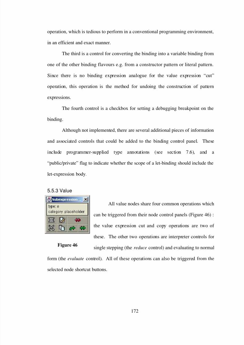
7/31/2019 Visual Fp Environment
http://slidepdf.com/reader/full/visual-fp-environment 182/312
operation, which is tedious to perform in a conventional programming environment,
in an efficient and exact manner.
The third is a control for converting the binding into a variable binding from
one of the other binding flavours e.g. from a constructor pattern or literal pattern.
Since there is no binding expression analogue for the value expression “cut”
operation, this operation is the method for undoing the construction of pattern
expressions.
The fourth control is a checkbox for setting a debugging breakpoint on the
binding.
Although not implemented, there are several additional pieces of information
and associated controls that could be added to the binding control panel. These
include programmer-supplied type annotations (see section 7.6), and a
“public/private” flag to indicate whether the scope of a let-binding should include the
let-expression body.
5.5.3 Value
All value nodes share four common operations which
can be triggered from their node control panels (Figure 46) :
the value expression cut and copy operations are two of
these. The other two operations are interpreter controls for
single stepping (the reduce control) and evaluating to normal
form (the evaluate control). All of these operations can also be triggered from the
selected node shortcut buttons.
172
Figure 46

7/31/2019 Visual Fp Environment
http://slidepdf.com/reader/full/visual-fp-environment 183/312
5.5.4 Lambda and Apply
Although the λ and apply syntax flavours do not
belong to a common class, apart from both being value
expressions, they do both share similar “curry/uncurry”
editing operations. The effect of currying and uncurrying
these nodes is explained in the earlier section on “browsing”
editing operations (section
5.1.3); these operations are triggered from buttons on
the λ and apply node control panels. The apply and λ
controls panels are shown in Figure 47 and Figure 48
respectively.
5.5.5 “Now-Showing” Item Controls
Pattern-sets, guard-sets and
lists all share the common layout
characteristic that they display only a
subset of their child sub-expressions at
a time (this is the “now-showing”
layout scheme described in section 4.2.9). Pattern-sets show one equation (with one
or more “left hand side” patterns and a “right hand size” value), guard-sets show one
Boolean guard value / consequent value pair, and lists show one list element value.
The node control panels for each of these syntax flavours (Figure 49) contain three
controls for manipulating child expression cases.
173
Figure 47
Figure 48
Figure 49

7/31/2019 Visual Fp Environment
http://slidepdf.com/reader/full/visual-fp-environment 184/312
An “add” operation is provided to introduce a new case: for pattern-sets, this
is an “empty” pattern, consisting of a variable binding in each of the pattern positions
and a placeholder in the value position; for guard-sets these are placeholders in the
guard/consequent positions; and for the list this is a placeholder as the new list
element. The new case is inserted into the sequence of existing cases in the position
after the currently showing one. The addition of a new (empty) expression case is
always type- and syntax- correct, so it is never prevented.
A “delete” operation is provided to remove the currently showing expression
case. In the case of pattern-sets and guard-sets, the removal of the last subset would
result in incorrect syntax, and this is disallowed by the editor.
For all three node flavours the semantics of the expression is dependent on
the order of expression cases: the third operation allows arbitrary re-ordering of cases
by swapping the currently showing expression with the succeeding one. Like the
case addition operation, the re-ordering of cases is correctness-preserving.
5.5.6 Let
The most complicated node control panel is that of
the let syntax flavour (Figure 50). The let syntax flavour
control panel contains all the controls necessary for the
manipulation of let bindings. A list box contains one
entry for each binding. The control panel contains
controls for adding a new binding, deleting a binding, and
making the binding’s defining expression visible. The
first and third of these operations can also be triggered
from controls on the node without the node control panel
174
Figure 50

7/31/2019 Visual Fp Environment
http://slidepdf.com/reader/full/visual-fp-environment 185/312
being opened.: the creation of new definitions while editing existing definitions make
these one-click (as opposed to the three-click version triggered from the node control
panel) controls worthwhile.
The “delete binding” operation is complicated by fact the binding may be in
use (i.e. there may be instantiated variables that refer to the binding). If the binding
were simply removed, the resulting program would be badly formed since the
variables would become implicitly undefined, a state of affairs unacceptable in the
VFPE. If a binding deletion would lead to this orphaning of variables, the
programmer is presented with a dialog explaining two choices. The operation can
always be canceled, in which case no modification is made to the program.
Alternatively, the binding removal can go ahead, with all the associated variables
being replaced by placeholder nodes. The resulting program is then guaranteed to be
type correct and have no undefined variables. If the “find all variables” or “find all
placeholders” operations (proposed in section 5.1.2 on navigation) were
implemented, it would be useful to allow them to be triggered at this point, either
after a cancellation (in order to examine the usage of the variables involved) or after
converting the variables to placeholders (to replace the deleted expressions with new
values).
It is suggested that the reader watch the “Recursive construction” example
applet at this point. This example introduces the more sophisticated editing
operations, including:
• Defining new functions.
• Opening definition windows
175

7/31/2019 Visual Fp Environment
http://slidepdf.com/reader/full/visual-fp-environment 186/312
• Building pattern expressions
• Opening node control panel windows
• Adding new cases to pattern-sets
• Use of the “apply functions” switch, creating variables from user-defined
bindings
• Saving programs.
• Watching program types evolve during construction.
The information presented in this applet is quite densely packed, so it is
probably worth viewing several times. After watching the applet play, the reader
may want to re-read the previous sections and then review the applet.
5.6 Incremental Syntax Checking
A fundamental property of the VFPE is that it is a supervising editor that
enforces syntactic correctness for the program being edited. This section discusses
how this is achieved and some of the issues that this correctness constraint
introduces.
Before any modifications are made to a program as a result of an editing
operation, the VFPE performs a number of checks to ensure that the program
remains syntactically correct. If the checks determine that the operation would result
in an incorrect program, the operation does not go ahead. The program remains
unchanged, the expression currently held by the cursor is not dropped, and an error
message is displayed to the user.
The editing checks fall into two groups. The first group consists of the
checks made for each of the context-sensitive operations to ensure that textual
176

7/31/2019 Visual Fp Environment
http://slidepdf.com/reader/full/visual-fp-environment 187/312
information entered is well-formed. An examples of this kind of check are the
requirements that the types entered when adding a new constructor function to a
datatype are valid type expressions and contain only valid type variables. Provided
that the entered information is of the right form, the operations will always leave the
program in a correct state.
The second group of operations are the checks performed on each attempted
drag-and-drop operation. Each operation is first tested to ensure that the particular
combination of grabbed expression type and target site represents a supported editing
operation. Attempting to drop one literal expression onto another, for example, has
no valid interpretation in the current implementation, and is rejected. If the operation
is one that is understood by the editor, then two further tests are applied. Firstly, the
program that would result if the operation were to go ahead is tested to ensure that it
is type-correct. The VFPE type checking system is covered in its own chapter and is
not discussed here, other than to say that to succeed the type inference system must
be able to find a correct type for the program that would be created if the editing
operation were to go ahead. Secondly, variables in the modified expression are
checked to ensure that they remain in their correct binding scope.68 The checking
procedures referred to here correspond to the types of static checking usually
performed by a compiler, including conformance to the language grammar, type
checking and dependency analysis. There are other syntactic tests that can be
applied to a program to disallow (or warn of) potential errors, such as completeness
of pattern-matching sets or guarantees of termination for recursive programs (e.g.
such as [Whittl 97] mentioned in chapter 2). These are much less common in
68 In fact we get the scope checking as a side-effect of the type checking; it isn’t performed
separately.
177

7/31/2019 Visual Fp Environment
http://slidepdf.com/reader/full/visual-fp-environment 188/312
functional programming languages than the checks described above, and are not
implemented in the VFPE.
Since the initial “empty” VFPE program (a prelude node with a placeholder
body) is syntactically correct, and since the checking process ensures that every
editing operation preserves correctness, it follows inductively that every program
constructed with the VFPE must be syntactically correct. Similarly, provided that
the initial program is correct, any program edited via the VFPE will remain correct.
The timing of the checking procedures (i.e. the fact that they occur as the
program is edited rather than as part of an explicitly triggered compilation pass) is a
fundamental difference between the VFPE and conventional programming
environments. It has a number of significant consequences.
The most obvious consequence is that error feedback is immediate and is
directly related to the previous action. This is of great value in pinpointing the
source of the problem. Since only one error is ever reported at a time, the dual
problems of long errors lists and cascade errors (errors caused by previous errors,
which disappear when the first error is fixed) do not occur. The immediate error
feedback means that incorrect code cannot serve as the foundation for newly added
code. This is perhaps not really a problem in the textual case, where it is equally
easy to edit any part of the code, but for a structured object editor like the VFPE it is
somewhat more difficult to edit interior portions of the structure than the fringes, so
the fact that erroneous code cannot be used as the foundation for code added later is
quite important.
A text editor allows complete freedom in the construction of programs.
Programs can be written in any order the programmer pleases, and can occupy any
178

7/31/2019 Visual Fp Environment
http://slidepdf.com/reader/full/visual-fp-environment 189/312
intermediate state during the process. This is not the case with the VFPE (and for
any editor tool which enforces syntactic correctness), which raises an important
question. Is there a legal sequence of editing operations for every possible legal
visual program ? It is conceivable that there might be a legal (i.e. syntactically
correct) program which is impossible to construct because there is no path of editing
operations that leads to it.
What follows is an outline of a proof that this is not the case i.e. that every
finite correct program is in fact constructable. For the sake of clarity a simplified
version of the VFPE that has only variable bindings (i.e. no pattern matching) and no
user-defined data types is considered. The extension of a proof to these cases should
be straightforward.
Proof outline for VFPE editing completeness
Begin with any correct target program, and construct a list of editing
operations in the following way:
1. One by one, replace every literal node by a placeholder.
2. One by one, replace every variable node by a placeholder.
3. If there is a syntax node (not including the prelude) which has only
placeholder children (and in the case of a let node, where the let node
has no bindings), replace the node with a placeholder.
4. If there is a pattern-set, guard-set or list node with more than one
case, where one case has only placeholder children, remove that case.
5. If there is a let abstraction with a binding with a placeholder body,
remove that binding.
179

7/31/2019 Visual Fp Environment
http://slidepdf.com/reader/full/visual-fp-environment 190/312
6. Repeating 3, 4 and 5 will result in a program which is the prelude
node with a placeholder child i.e. the empty program. Note that if the
program is not empty a node matching one of 3, 4 or 5 can always be
found: starting at the prelude node, tracing down a line of non-
placeholder children will eventually come to a node, case or let
binding with only placeholder children, since programs are acyclic69
and all the leaf nodes have been replaced with placeholders in steps 1
and 2.
Each deletion operation preserves program correctness. Deletion of variables
of course does not cause variables to go out of scope (we are deleting occurrences,
not bindings at this stage). Also, deletion of variables and placeholders maintains
type correctness since removal of these nodes only ever removes restrictions on the
types of other nodes70. The same applies for the deletion of empty cases and let
bindings: removing these nodes only ever removes type restrictions. Since the
program we started with is assumed to be correct and the deletion operations
preserve correctness, each intermediate program must be correct.
Now, taking the complete list of deletion operations, build another list of
corresponding constructive editing operations in reverse order . To see that this is
possible, note the following:
1. Literal nodes are simply constructed and attached.
2. Since all variable nodes are constructed after all abstractions and their
bindings are complete (since the deletions occurred before any
69 Note that the presence of cycles in the program graph, considered in section 3.4, would
complicate this proof.
70 This would be the nub of a rigorous proof, and would be related to a proof of the
correctness of the incremental type inference algorithm of section 7.4.2.
180

7/31/2019 Visual Fp Environment
http://slidepdf.com/reader/full/visual-fp-environment 191/312
removal of bindings), the corresponding binding node will always be
available to create the variable.
3. New conditional, application and λ nodes are always added with
placeholder children: these can be created from the pallet. Pattern-set,
guard-set, list, and let abstraction nodes are created with the minimum
number of cases and with placeholder children: again, these are the
form created from the pallet.
4. Addition of new cases to pattern-set, guard-set and list nodes always
adds cases with placeholder children, exactly as the editing operations
do.
5. New let bindings are created with placeholder bodies.
This list of construction operations thus begins with the empty program, uses
only operations provided by the editor, and culminates in the original program.
Since it recreates exactly the same list of partial programs (in reverse order) as the
deletion operations, all of the intermediate programs are correct.
Although it is possible to construct all correct visual programs, there remains
a potential problem with the ease with which a program modification can be made.
It is always possible to get from any program to any other by pruning the original
program back to a single placeholder and building the target program, but this is
hardly practical for any non-trivial modification. In the textual case, it is a
straightforward matter to come up with a minimal (or at least small) sequence of
edits that will modify a program in the desired way.71 For supervising editors like the
71 The ease with which changes to textual code can be accomplished can be misleading. It is
almost never as simple as just moving fragments of code about: unless care is take it is easy for
variables to go out of scope (or be incorrectly captured by another binding), for example. Even if a
181

7/31/2019 Visual Fp Environment
http://slidepdf.com/reader/full/visual-fp-environment 192/312
VFPE there are at least two complications in accomplishing a desired program
modification. Firstly, arbitrary changes are not allowed: the modification must be
accomplished by a sequence of supported editing operations. Furthermore, every
intermediate state must be correct: it is not possible to leave portions of the code
“dangling” to be fixed in later operations. This is a potentially serious problem
inherent in the operation of any correctness-preserving editor.
We claim that the strictures of the supervising editor environment (a) impose
an overhead on the operation of the editor, but (b) not an intolerable overhead. We
cannot offer a formal proof or rigorous experimental evidence for this claim, but we
feel that any attempt to use the VFPE to perform any non-trivial program editing will
reveal (a); and once a few basic techniques are learned, (b). It seems that there is
usually a simple means of accomplishing desired edits while maintaining program
consistency. As illustrative evidence, a few of the techniques for dealing with the
program correctness restrictions are explained below.
It is suggested that the reader view the “Tree interior editing” and “Function
generalisation” example applets at this point. These two examples show editing
sequences that are more complex than straight-forward program construction.
The VFPE’s attachment method of constructing programs operates only at the
boundary (i.e. the leaves) of a program. It is a very unusual piece of software indeed
that is constructed and never again altered, so it is important to show an example of
how the interior of a VFPE program can be modified. The “Tree interior editing”
correct sequence of edits is devised, it is easy to lose track of progress and leave out edits if the
sequence is long.
182

7/31/2019 Visual Fp Environment
http://slidepdf.com/reader/full/visual-fp-environment 193/312
applet shows how an expression can be temporarily moved “sideways” in order to
insert new nodes into a program. The general applicability of this technique can be
seen by noting the following facts.
• Since a new empty let node can be safely inserted as the new head of any
value node in a program, the technique can be applied anywhere.
• Cutting an expression is always safe.
• Any expression can be safely attached to an empty let binding, so any
expression can be moved sideways.
• The moved expression (or part of it) will be able to be transplanted back
if the edit has correctly made room for it.
This is a important editing technique in the VFPE. Without it, it would still
be possible to edit the interior of programs, but at the cost of cutting the program
back to the edit location and rebuilding it.
The “Function generalisation” applet shows a series of editing operations
whereby a function is converted into a more general version of itself: the generalised
function is parameterised by a higher-order function that implements part of its
functionality. The example demonstrates several important techniques.
• Cut and attach operations are used to move a definition body expression
from one function to another.
• Partial function application and the curry/uncurry transformation to deal
with the different types of the old and new functions.
• The example shows an expression being loaded from disk.
• The program modification is tested by constructing a test expression and
evaluating it with the interpreter.
183

7/31/2019 Visual Fp Environment
http://slidepdf.com/reader/full/visual-fp-environment 194/312
5.7 Editing Operation Summary
The organisation of the preceding sections, arranged in terms of different
sorts of GUI actions, does not give a clear overview of the editing system. Here is a
summary of the VFPE editing operations.
Browsing operations
operation actionview expression type and comment let cursor linger over syntax node
show function definition right-click on binding name on letnode
show parts of pattern, guard and listexpressions use < and > arrows on syntax node
toggle visibility of let bindings use < and > arrows on let node
toggle visibility of apply node checkbox in apply node control panelcurry/uncurry function application button in apply node control panel
curry/uncurry λ-abstraction button in λ node control panel
toggle visibility of λ in function definition button in let-binding node controlpanel
Editing operations
operation actioncreate built-in syntax click on pallet syntax button
create library function click on pallet library function button
create variable click on binding node
create literal type value into literal field on palletand press return
attach value expression drop value onto placeholder
attach pattern drop literal or constructor functiononto variable binding
attach (insert) let in interior of expression drop empty let node onto value node
grow a new function click + button on let node
grow a new case for pattern, guard or list button on control panelgrow a new datatype constructor function button on datatype node control panel
rename binding button on binding control panel
re-order cases in pattern, guard or list button on node control panel
detach value (simplify to Placeholder) select (click) node and press cutbutton on control panel
detach pattern (simplify to variablebinding)
button on binding node control panel
184

7/31/2019 Visual Fp Environment
http://slidepdf.com/reader/full/visual-fp-environment 195/312
shrink let (remove function definition) button on let node control panel
shrink (remove case from) pattern, guardor list
button on node control panel
detach (collapse) empty let from interiorof expression
button on let node control panel
shrink (remove) constructor functionfrom datatype
button on datatype node control panel
copy value (duplicate) select node and press copy button oncontrol panel
destroy grabbed expression click on delete button on pallet
5.8 Editor Operation Statistics
In order to test the assumptions about the relative frequency of the different
editing operations, the VFPE was instrumented to output a record of each editing
operation.72 Statistics for the construction of two programs (a parser-combinator
based LISP parser, and a red-black tree finite map implementation) have been
gathered and collated. While only a small code corpus (about 200 lines of Haskell
code), we think they do represent fairly typical function programs. Section 11.2
contains details of the measurement.
The general partition of operations into the categories defined in section 5.7 is
shown in Figure 51. The fact that 85% of editing operations are single-click actions
(43% create, by clicking on pallet buttons or bindings, and 42% attach, by clicking
on placeholders or variable bindings) supports the decision to reserve drag-and-drop
actions for these operations. Consider, for example, the possibility discussed in
section 5.9 of using drag-and-drop operations for function definition. The data
presented here shows the that addition of new definitions accounts for less that 4% of
operations (since the 4% grow operation includes extension of lists, guard-sets and
72 This includes only program-modifying operations, not purely navigational ones.
185

7/31/2019 Visual Fp Environment
http://slidepdf.com/reader/full/visual-fp-environment 196/312
pattern-sets as well as introduction of new let bindings), so the impact in terms of
number of user actions would be marginal.73
In the process the editor was also instrumented to record timing information
for each type-checking operation, in order to evaluated the effectiveness of the type
checking optimisations. These results are shown in section 7.5.
73 It is possible that the existence of drag-and-drop function definition encourage to the
creation of programs with a greater number of definitions; but even this effect, say, doubled the
number of definitions the point would remain valid.
186
Editing Operation Categories
(2474 operations)
7%
42%
43%
4%2%0%2%
rename
attach
create
grow
copy
shrinkdetach
Figure 51

7/31/2019 Visual Fp Environment
http://slidepdf.com/reader/full/visual-fp-environment 197/312
5.9 Workspaces
This section is devoted to the concept of “workspace” editing windows, a
feature considered for but not implemented in the VFPE.
Every sub-expression appearing in the VFPE editor is an integral part of a
program, in the sense that all sub-expressions can trace their ancestry back to the root
of the program expression. A workspace, in this context, is a container for temporary
“unattached” expressions. Expressions would be added to a workspace by dropping
them into the workspace and removed by cutting them from there. Workspaces
would have several uses.
The most attractive use of the workspace is as a temporary “shunting” area
for expressions during editing. It is often the case that while re-arranging the interior
of an expression one needs to, in effect, say to the editor “hold this for a moment”.
Section 5.6 shows examples of how this can be accomplished in the VFPE: having a
workspace would simplify this process.
Workspaces can also be used for constructing and holding expressions to be
evaluated by the interpreter. Test expressions constructed during programming, in
order to test individual components, are not usually permanent parts of the program74.
When testing or running a program, it is often the case that the same computation
needs to be run with slightly varying input data. Similarly, when debugging, the
piece of code being edited usually needs to be run repeatedly with identical input
data. In either case a workspace facilitates the process, since a test expression can be
constructed and then duplicated (and possibly modified) in the workspace as often as
necessary without disturbing the rest of the program.
74 Although documentation describing how the code has been tested should be.
187

7/31/2019 Visual Fp Environment
http://slidepdf.com/reader/full/visual-fp-environment 198/312
Another use of a workspace is to display a copy the expression being edited,
as a reference when making some structural change where an error might be made.
A digression will be made at this point to describe an alternative mechanism
for defining functions which centers around workspaces. The definition of functions
occupies a central role in functional programming: in one sense functional programs
can be considered simply as collections of function definitions.
With the VFPE, function definition has two stages. First, a new “empty”
function is declared by using the “add binding” control of a let node. Secondly, the
function is defined by constructing the binding’s body expression (i.e. filling in the
body’s placeholder nodes). The process is incremental: changes to the function
definition are made step-by-step, and the function can be used at any point after it is
declared.
The alternative function definition mechanism involving workspaces is
transaction oriented rather than incremental. A function is defined by first
constructing its defining body expression in a workspace, and then dragging the
definition into a “library” area where it becomes a new binding, or replaces an
existing definition. In order to edit a function, one drags the binding from the library
area onto the workspace, which creates a copy of definition body. This is modified
in the workspace and dragged back to the library to update the definition. The
primary benefit of this scheme is that function definition becomes an entirely drag-
and-drop action: one takes a definition and inserts it “into” a library. Figure 52
shows how a workspace of this sort might look.
The main disadvantage of this scheme is that it circumvents the incremental
correctness checking when function definitions are being edited. With the standard
188

7/31/2019 Visual Fp Environment
http://slidepdf.com/reader/full/visual-fp-environment 199/312
VFPE scheme, function definitions are edited directly, and every operation is
checked not only to make sure that the function definition is internally consistent, but
that it does not conflict with the function’s use anywhere else in the program. With
the alternative workspace scheme, function definitions are not modified directly. It
would be possible to change a function so that while it is locally correct, it becomes
incompatible with the rest of the program. These errors would be flagged when the
function is re-defined, but by then it is “too late” as it were because (a) the editing
step that caused the problem may have been buried under several others and (b) a
single editing operation may cause multiple errors to be flagged. This is a step back
towards batch compilation and away from the strict incremental correctness property
that is a primary goal of the VFPE.75
75 A hybrid scheme whereby functions are initially defined by dragging expressions into a
library but thereafter edited directly would be possible. It would be fairly easy to incorporate
something like this into the VFPE, allowing value expressions to be dragged onto the “+” button on
let nodes to automatically add a new binding and set its body to the grabbed expression.
189
Figure 52
quicksort
partitionCons if
<x xs
x ?
? ?
++
++quicksort
left ? ?
workspace library

7/31/2019 Visual Fp Environment
http://slidepdf.com/reader/full/visual-fp-environment 200/312
Another complication with this drag-to-define mechanism is the
representation pattern matching. For the introduction of simple bindings such as
named functions, the “drag to library” operation is adequate. For structured
bindings, such as where a constructor pattern is used to return more than one value
from a function76, a more complicated mechanism in needed. The instantiation in the
workspace of objects that are combinations of bindings and value expressions77
becomes necessary. The need for extra binding-oriented drag-and-drop operations
would somewhat blunt the impact of the VFPE’s very simple drag-and-drop
metaphor.
Similarly, another minor complication is the need to instantiate placeholder
nodes. In order to introduce a function with an undefined body (i.e. declaring a
function before defining it, which is necessary for recursive functions or top-down
programming style) under the workspace/library scheme, a placeholder node would
have to be created in the workspace so that it could be dragged to the library.
Instantiating placeholders is never necessary with the VFPE; placeholders simply
appear and disappear where necessary.
The idea of providing a workspace as an unstructured scratch area is
attractive but not without its problems. Although expressions in workspaces appear
to be disconnected from the rest of the program, they must still be consistent with the
program if the incremental correctness checking is to operated within the workspace.
This implies that each workspace must have an “effective location” within the
76 See the description of the VFPE constructor binding syntax flavor in 4.2.15 for an
example of this useful feature.
77 These are actually the “binding headed value expressions” described in section Let.
190

7/31/2019 Visual Fp Environment
http://slidepdf.com/reader/full/visual-fp-environment 201/312
program’s syntax tree78, so that the type and scope checking systems can operate.
This somewhat limits the original intention of having free floating scratch areas,
since the workspaces either need to be explicitly linked to the main program in order
to show their effective location, or be unlinked, and risk the confusion resulting from
having identical looking workspaces behaving differently.
If correctness checking is to operate in workspaces, then what effective
locations should be used for each workspace, and how should these be determined ?
No single location in the program is adequate: workspaces located at the top of the
program cannot contain locally defined functions appearing lower in the syntax tree,
and thus cannot be used for testing local functions. Locations lower in the syntax
tree suffer from the same problem: local definitions of their sibling nodes are
similarly inaccessible. Multiple workspaces, or workspaces with variable locations
are necessary.
One rather complex solution might be for empty workspaces to have an
indeterminate location, and to narrow the location automatically as expressions are
constructed in it, using some rule such as “use the highest location for which all the
expression’s variables are in scope”. For example, consider the case where a prelude
function application is dropped onto such a workspace. Its effective location would
be at the very top of the program, just below the prelude abstraction node. Now if a
local variable from lower in the program replaces one of the placeholders on the
workspace, the effective location will need to move down the tree until the variable
is in scope. This could continue until an attempt is made to add a variable to the
assemblage for which no legal effective location exists. The beauty of this solution
78 Actually, each expression in each workspace requires an effective location, but allowing
different expressions on the same workspace to have different effective locations is too confusing to
consider.
191

7/31/2019 Visual Fp Environment
http://slidepdf.com/reader/full/visual-fp-environment 202/312
is it does not require any programmer attention over and above the usual drag-and-
drop mechanism. Unfortunately, the hidden rules that cause workspace’s rejections
of incompatible additions could be very frustrating indeed.
Another, simpler, solution is to associate each workspace with a let node (and
vice versa). Under this scheme, workspaces are the windows onto the content of let
expressions, and the means by which definitions are made and used.
The current implementation of the VFPE does not provide workspaces.
However, with a little effort a very similar effect can be achieved by creating
temporary bindings in nearby let expressions (or inserting temporary let expressions
for the purpose), and using the binding’s body as scratch space.
192

7/31/2019 Visual Fp Environment
http://slidepdf.com/reader/full/visual-fp-environment 203/312
6. External Forms
It is not the aim of this thesis to tackle all the problems and opportunities
associated with storage and re-use of functional program code. The particular
challenges posed by the VFPE in the storage of visual functional expressions do
however raise some issues worth considering. The current VFPE implementation
offers two external forms for functional programs.
6.1 Serialised Functional Expressions
As described in the previous chapters, the fundamental unit of functional
program code in the VFPE is the value expression. Since value expressions are the
basis for both program visualisation and manipulation at all levels, it seems natural to
also make them the basic unit of program storage as well. This novel approach is
deliberately adopted in the VFPE, despite the problems it introduces, in order to
emphasise the central metaphor of functional expressions as objects. By allowing the
same (drag-and-drop) expression manipulation operations to be applied to the saving
and loading of code, the “functional expressions as objects” metaphor is extended
beyond the VFPE application and into the file system of the underlying platform. In
this domain users can manipulate functional expressions as just another file type, in
all the usual ways.
Allowing arbitrary expressions in a program to be saved and loaded
represents a departure from conventional programming environments. Most
programming languages include as part of their syntax special “top-level” structures
(such as modules, packages and classes) which delineate portions of code that can be
193

7/31/2019 Visual Fp Environment
http://slidepdf.com/reader/full/visual-fp-environment 204/312
saved and loaded as a single unit. The module syntax serves the purpose of defining
the boundaries of the code unit.
All stored software objects (which we call units in this section, be they
programs, modules, scripts, libraries, object modules or what-have-you) have,
implicitly or explicitly, two interfaces which define their boundaries. These are the
points at which the module needs to cooperate with other units in order to fulfill its
function.
One interface is the unit’s dependencies: the set of objects utilised by the unit
but not defined by it. A unit relies on the fact that imported objects conform to some
structural or behavioral contract even though their implementations are opaque. If a
unit does not explicitly import any objects, then its only dependencies are on
“standard library” objects in the language in which it is written.
The other interface is the set of objects it exports to other units. Software
with an empty export set is commonly called a program or an application; otherwise
it is a library (or a module, or a platform).79
The purpose of any software storage format is to draw a boundary around a
body of code and define these interfaces. Any stored software unit must contain
enough information about both boundaries, so that it can be correctly linked with
other units. In a conventional module system the top-level syntax of a source code
unit usually records this information. If arbitrary functional expressions are to be
stored as units (rather than requiring a special syntactic structure for storable
expressions), some way of implicitly determining and recording the expression
boundaries is needed.
79 Actually, we could say that even a stand-alone program has these interfaces. A program
exports its functionality (to human beings or other processes), and imports dependencies in structure
of its input data. But that’s a little too esoteric for this discussion.
194
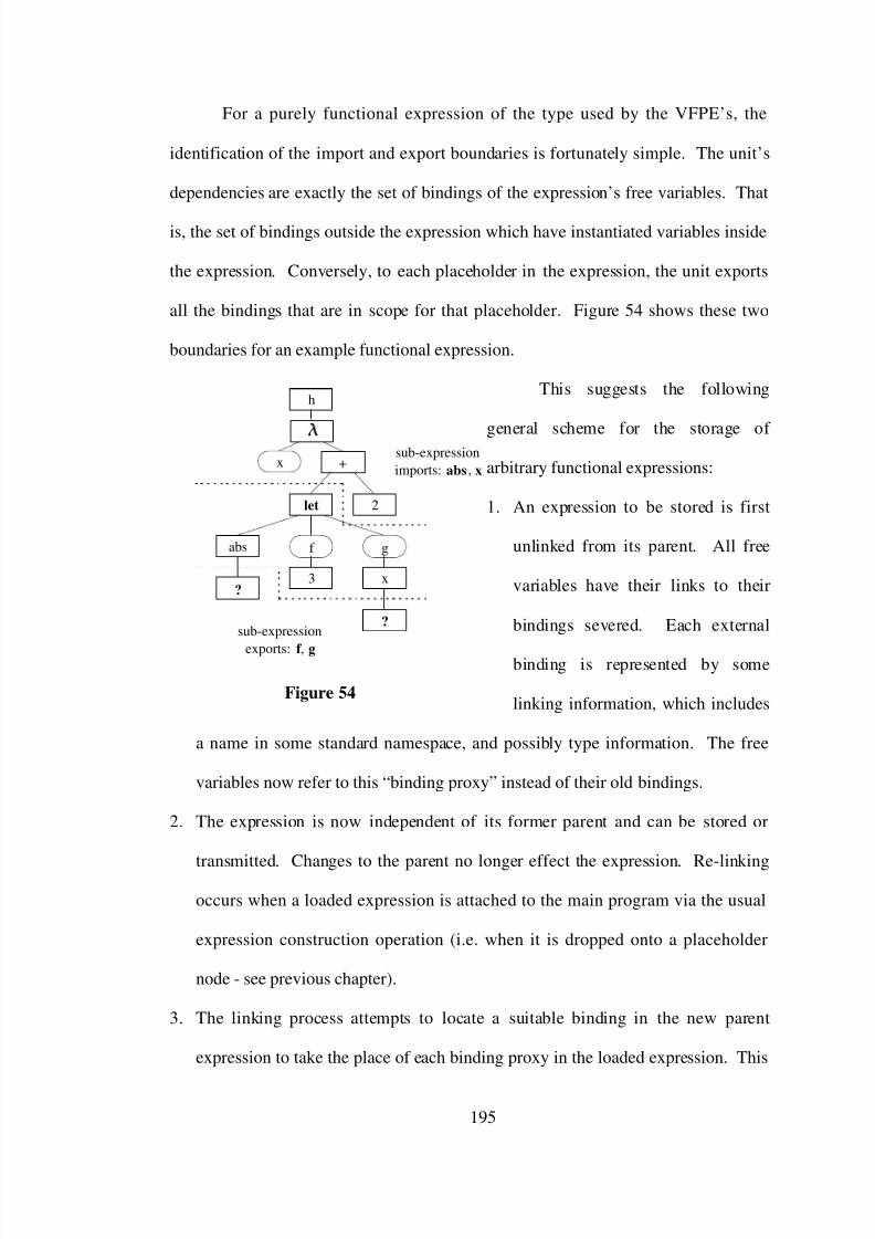
7/31/2019 Visual Fp Environment
http://slidepdf.com/reader/full/visual-fp-environment 205/312
For a purely functional expression of the type used by the VFPE’s, the
identification of the import and export boundaries is fortunately simple. The unit’s
dependencies are exactly the set of bindings of the expression’s free variables. That
is, the set of bindings outside the expression which have instantiated variables inside
the expression. Conversely, to each placeholder in the expression, the unit exports
all the bindings that are in scope for that placeholder. Figure 54 shows these two
boundaries for an example functional expression.
This suggests the following
general scheme for the storage of
arbitrary functional expressions:
1. An expression to be stored is first
unlinked from its parent. All free
variables have their links to their
bindings severed. Each external
binding is represented by some
linking information, which includes
a name in some standard namespace, and possibly type information. The free
variables now refer to this “binding proxy” instead of their old bindings.
2. The expression is now independent of its former parent and can be stored or
transmitted. Changes to the parent no longer effect the expression. Re-linking
occurs when a loaded expression is attached to the main program via the usual
expression construction operation (i.e. when it is dropped onto a placeholder
node - see previous chapter).
3. The linking process attempts to locate a suitable binding in the new parent
expression to take the place of each binding proxy in the loaded expression. This
195
Figure 54
h
x +
let
?
f
3
g
?
2
abs
x
sub-expression
imports: abs , x
sub-expression
exports: f , g

7/31/2019 Visual Fp Environment
http://slidepdf.com/reader/full/visual-fp-environment 206/312
is done by walking up the tree from the attachment site and attempting to match
the information in the binding proxy with a binding in the parent expression. If
some of the matches cannot be made then the parent expression cannot satisfy the
dependencies of the new expression and the operation is disallowed.
The key to the process is the matching of each binding proxy in the stored
expression with a function that is equivalent (in some sense) in the new context. The
intended effect is to restore the original functionality of the stored expression by
replacing its free variables with references to the “same” function present in the new
context.
The usual approach to matching imported and exported symbols from
different code units is to match textual symbol names in some agreed-upon
namespace. In a conventional module system each module defines a namespace
(with module names existing in a single universal namespace); individual import
statements specify from which module (and thus namespace) each symbol is to be
imported.
In a system without explicit syntactic module boundaries, how can the
namespaces for this matching process be specified ? This can be done by allowing
programmers to specify an optional namespace property for each abstraction (or, if a
finer grain of control is desired, each binding) in a program. When an expression is
being unlinked in preparation for storage, the namespace of each free variable (taken
from the abstraction where the variable is bound) is recorded in the binding proxy.
When the stored expression is re-attached, the search for corresponding bindings
must match both binding names and namespaces.
196

7/31/2019 Visual Fp Environment
http://slidepdf.com/reader/full/visual-fp-environment 207/312
This linking system is in some ways more general than a conventional
module system. For instance, it allows for different namespaces to interpenetrate
each other’s scope, it allows for the export of λ-bound values as well as let-bound
values, and so forth. It is not known whether the extra generality would be useful, or
just a source of confusion.
Something that should be noted is that within a VFPE program binding
names are used only as decorations for programmers: the maintenance of the
variable/binding relationships is quite independent of binding names. As a result
bindings can be introduced and renamed without fear of name clashes, and
expressions can be moved within a program without unexpected “captures” of
variables by bindings. The use of binding names in the linking/unlinking process
breaks this property. In a stored expression, where there can be no internal link
between a free variable and its binding to indicate the identity of the variable, some
other piece of information must be used to identify the variable. Conventional
programming languages show that a binding name within some module or library
namespace (with concomitant documentation) adequately serves this purpose.
In a visual programming environment, another approach to matching
bindings during the linking of loaded expressions is to allow (or require) programmer
intervention. Under such a scheme the programmer would be presented with each
binding proxy (or perhaps just those for which counterparts cannot be automatically
located) and asked with which existing binding it should be associated. While this
scheme might be useful for remedial action when there are a few bindings that
cannot be automatically re-linked, it would be too laborious as the primary linking
mechanism for an program involving even moderate-sized modules.
197

7/31/2019 Visual Fp Environment
http://slidepdf.com/reader/full/visual-fp-environment 208/312
Having described a potential solution to the problem of storage of functional
program fragments, it must now be admitted that the VFPE implements only a very
restricted version of this system. The VFPE allows expressions to be serialised only
if the only free variables contained within them all refer to prelude bindings. In
other words, expressions can be saved provided that they are self-contained apart
from the built-in functions declared in the standard library prelude.
It does not therefore allow the storage of code that itself depends on other
stored code, which is an essential requirement for a full module system that allows
proper partitioning of large projects, separate development, and code reuse. On the
other hand, it does relieve the necessity for code fragments to depend implicitly on a
fixed set of library functions (since the VFPE prelude can be replaced); it does allow
the creation of simple code modules as let expressions; and it does demonstrate a
form of the “unlink-store-link” mechanism for storing function expressions outlined
above.
Textual languages all inherit a straightforward translation to binary form from
the character set in which they are encoded (ASCII in a vast majority of cases). As a
result they benefit from a set of common tools such as parser generators,
documentation generators, code formatters, revision control systems, generic text
processing tools and so forth. The familiarity of the structure of textual languages
encourages the creation of tools for automated analysis and manipulation of
programs by other programs.80 The same is not true for visual languages, since there
is no standardised set of visual programming language symbols, nor are there any
80 One example of this is the use of the C language as a portable assembly language.
198

7/31/2019 Visual Fp Environment
http://slidepdf.com/reader/full/visual-fp-environment 209/312
general-purpose standards for the serialisation of tree or graph structures.81 There
has been research into formal two-dimensional/visual grammars (e.g. [Golin89]), but
these remain largely of academic interest. Each visual language must therefore
define its own translation to binary form for external storage, a fact which weighs
against the proliferation of visual languages.
The serialisation format used by the VFPE is based on the standard Java
object serialisation system. Although this was simple to implement, hindsight has
revealed it to be a mistake. The use of the Java object serialisation system
unnecessarily pads each stored object; it makes the stored forms opaque82
to any
language other than Java; it makes hand-editing (invaluable for debugging the
development environment) impossible; and it results in objects that are very brittle to
changes in the VFPE. A better approach would have been to define a suitable format
independent from the implementation details of the VFPE. The following section
discusses the pros and cons of using an existing functional language (or a restricted
subset thereof) as an interchange format.
6.2 Haskell Code Fragments
The second external form provided by the VFPE is the ability to write
fragments of Haskell code. The Haskell export facility is rather primitive: it allows
the bindings of a let expression to be written as a set of Haskell functions, with the
same restrictions described in the previous section (i.e. no free variables unless
they’re prelude bindings).
81 Applications descended from LISP inherit the s-expression tree syntax, but this has never
really taken off as an interchange format. In recent times XML has begun to be come accepted as a
common lexical standard for tree-structured data.
82 Or at least extremely difficult to manipulate.
199

7/31/2019 Visual Fp Environment
http://slidepdf.com/reader/full/visual-fp-environment 210/312
The motivation behind providing a textual export facility for the VFPE is to
treat the textual target language as a compiler back-end, in order to take advantage of
existing compilation and optimisation tools.
A problem not considered in this project is that of providing translations
between visual code and human-readable textual code. Such a facility would allow
the visual and textual programming environments to act as (hopefully
complementary) alternative views of the code. [Reekie 94] is a study of the problem
of translating textual Haskell into a visual form.
While it might be useful to be able to switch to and from textual code, the
practice might smother any tendency for the development of a visual programming
style: programmers might refrain from writing visual programs they know will not
translate into “good” textual code. Since the structures built by programmers with
the visual editor would be degraded or eliminated each time a program was saved
and loaded, any advantage of a uniquely visual style of programming would never
accrue. For this reason, even if effective textual translation tools are provided, it is
probably a good idea to provide a storage format that captures the full details of
visual programs.
The “IO example” applet shows an example of the Haskell export facility
being used. It is suggested that the reader view that example at this point.
200

7/31/2019 Visual Fp Environment
http://slidepdf.com/reader/full/visual-fp-environment 211/312
7. Type Checking
With respect to the structure of the type domain and the assignment of types
to expressions, the VFPE’s type system does not differ from type systems of existing
languages. The novelty of the type system employed in the VFPE is in its interaction
with the program editing operations: it is in that context that it presents a new facility
for programmers and a new implementation challenge. Although prompted by and
implemented in the VFPE, the techniques described in this chapter should be
applicable to any programming environment with a similar type system.
7.1 The VFPE Type System
Briefly put, the VFPE has a strong, static, implicit type system based on
Hindly-Milner polymorphic types [Milner 78]. It is similar to a simplified version of
the type systems of languages such as ML, Miranda or Haskell.
Before the peculiar aspects of the VFPE’s type system are discussed, the
previous description will be expanded upon in order to provide some background,
and to explain the motivation for choosing such a type system.
Strongly typed languages are those that enforce type checks that ensure that
all operators are applied to the correct type of data before executing them. Strong
type checking ensures that programs do not cause execution of badly typed primitive
operations; or if they do, that execution halts rather than continuing with undefined
behaviour.
Static typing refers to the fact that some type-checking is done at compile
time, rather than being delayed until the program is running. Static typing has two
201

7/31/2019 Visual Fp Environment
http://slidepdf.com/reader/full/visual-fp-environment 212/312
great advantages. Firstly, a great number of logical errors can be caught by compile
time checking, saving time-consuming test runs and execution tracing to determine
the location of the faults. Secondly, if the compiler can prove that an operation is
only ever supplied with data of the correct type, run time type checks can be omitted
from the code, speeding execution.
Implicit typing means that types of program objects are inferred from the
types of their constituent parts, and need not be explicitly expressed by the
programmer. Programmer type annotations are a good thing, since they aid the
human comprehensibility of the code and provide an extra check for the compiler on
the intentions of the programmer. Implicit typing (type inference) allows the
programmer to choose the level of type annotation that is appropriate for the
program.
Parametric polymorphism allows compound types to be constructed from
other types and type variables. This allows collections of types that are
“structurally” identical (lists of integers and lists of booleans, for example) to be
represented by a single type. The type is parameterised by one or more type
variables, which can take on the value of other types to yield a whole family of types.
In terms of actual types supported, the VFPE includes the usual suspects:
fixed range integers and floating point numbers, characters, booleans, lists, tuples (up
to arity 5), and a few additional useful types borrowed from Haskell (the Maybe type
and IO monad type). As mentioned in the syntax chapter, there is the facility for
introducing user-defined algebraic data types.
Beyond the parametric polymorphism described above, some of the VFPE
primitive functions implement what is referred to as “ad hoc” polymorphism. The
202
7/31/2019 Visual Fp Environment
http://slidepdf.com/reader/full/visual-fp-environment 213/312
ordering and equality predicates appear to be defined over arbitrary types (i.e. they
have type a -> a -> a): in fact they only work for the atomic types. This is an
ugly but pragmatic measure included to avoid either (a) having to a separate set of
functions for each basic type (the solution adopted for integer and floating point
numbers and the arithmetic functions), or (b) implementing a more complex function
overloading solution.
Ideally the VFPE should provide a more general ad-hoc solution, or a
systematic solution (a la Haskell type classes) to provide the more sophisticated
forms of polymorphism. It is not known what complications this would introduce in
the optimisation techniques described later in this chapter.
7.2 Visible Types
The idea of providing visible types is simple: the programmer can at any time
see the currently inferred most general type of any sub-expression in the program.
As described in section 5.1.1, types are made visible by simply letting the cursor
linger over a syntax node for a second or so, whereupon the type is displayed in a
pop-up information window. This section examines the “why” of the visible-types
mechanism, leaving the “how” to the next section.
Firstly, visible types are an aid to construction. When instantiating variables,
binding types, as well as names, help programmers to distinguish between a
function’s formal parameters. Similarly, when instantiating a library function for
addition to the program, function types are a valuable memory aid for identifying the
desired function, especially when selecting from a large library. On the other side of
expression construction, knowing the type of each placeholder may help prompt the
next editing operation.
203

7/31/2019 Visual Fp Environment
http://slidepdf.com/reader/full/visual-fp-environment 214/312
Secondly, the ability to query the type of sub-expressions helps the
programmer to verify the design. By watching the types as an expression is being
built, the programmer can check to see if the inferred type matches her expectations.
When browsing an unfamiliar program or trying to divine the workings of complex
expression, the ability to query the types of sub-expressions allows the programmer’s
tentative mental model of the expression to be verified or falsified. Another useful
feature that could be added to the VFPE would be the facility to add programmer
type annotations to bindings, and incorporate these into the type inference system as
an additional check.
Thirdly, visible types may have educational value, both for novice
programmers learning about values and types; and for understanding type inference.
Showing the types of expressions while adding and removing sub-expressions may
provide insight into the type inference and unification processes.
The purported advantages of visible types stated above are speculative, based
on the author’s programming experience and use of the VFPE. At the time of
writing, the author is not aware of any similar feature in other programming
environments that provides the same level of type information. In the case that it
turns out to be worthless, it can at least be ignored.
Types are displayed as textual strings
83
, appearing as they would in a Haskell
program [Hudak 92]. The fact that a large number of type expressions are potentially
visible raises an interesting issue with the presentation of type variables. In a
conventional programming environment, the scope of type variables appearing to the
programmer is limited. In the case of programmer-declared types the scope is a
83 See section 3.8 for notes on possible visual representation of types.
204
7/31/2019 Visual Fp Environment
http://slidepdf.com/reader/full/visual-fp-environment 215/312
single type expression, or a small collection of type expressions appearing as part of
a class or instance definition. In the case of the compiler-generated type expressions
that occur in error messages, the scope is generally the type expressions appearing in
the whole error message. . Figure 53 shows two examples of textual type
expressions, as they appear in program type declarations and type-checking error
messages. In either case the programmer or compiler is free to re-use type variable
names; the common practice in Haskell is to use variables from the sequence “a”,
“b”, “c” …
Internally, type inference algorithms can use hundreds (or thousands,
depending on the size of the program) of type variables during their operation. These
type variables are not intended for human consumption (they may not even have
names); if they are ever to be presented to the programmer they are usually translated
from their internal representation to a more palatable form just before display. The
VPFE, on the other hand, requires that the type variables remaining after type
inference is complete be made visible and intelligible to the programmer. There are
at least two issues here. For meaningful browsing, the same type variable name must
denote the same type wherever it appears. Since a type variable may appear in types
in widely separated parts of the program, the scope of the type variables is the entire
program. A type variable name cannot be re-used until every occurrence of the type
it formerly denoted has disappeared from the program.
Secondly, as well as being consistent in space (i.e. everywhere in the
program), type variables should be used as consistently as possible in time; that is,
the names of type variables should be disturbed as little as possible by editing
operations. This requirement is weaker that the previous one: the type inference
205

7/31/2019 Visual Fp Environment
http://slidepdf.com/reader/full/visual-fp-environment 216/312
system could re-assign every type variable name (or generate an entirely new set of
names) with each editing operation and still be perfectly correct. Having the type of
an (unchanged) function renamed from a -> b -> c to c -> a -> b (or
y -> z -> aa) after each operation would however be rather distracting,
especially if the editing operation had nothing to do with that function.
The current implementation of the VFPE strictly observes the first condition.
Although it has not been extensively tested, the algorithm used by the VFPE seems
to perform quite well with respect to the second condition as well.84
7.3 Incremental Type Checking
The goal of an incremental editing type system is essentially the same as for a
conventional batch compilation type system: to infer the most general correct typing
(the principal type) for each sub-expression in the program, or to report that no
correct typing exists. The difference is in how the typing is constructed, and what is
done with the type information afterward. In the conventional case, the type
inference algorithm starts with no type information (apart from the types of library
functions) and analyses the entire program, assigning and updating types for each
syntax node. The algorithm need only retain enough type information at any point so
that the algorithm can proceed, and so that meaningful error messages can be
reported. If the type inference succeeds, the typing generated can be discarded: it is
generally not used in further compilation.85
84 The VFPE uses the Java garbage collection hook to reclaim type variable names that go
out of scope. For some reason this seems to work quite well across Java implementations, despite the
fact that the Java language specification provides no guarantees on the operation of GC.
85 Actually, interpreters such as HUGS and GHCi fall somewhere in between the batch
compilation and visible types extreme. They record and make available the type of each identifiers
visible in the scope of the interactive environment.
206

7/31/2019 Visual Fp Environment
http://slidepdf.com/reader/full/visual-fp-environment 217/312
In the incremental case, the starting point is a principally typed program, and
the inference algorithm must inspect every editing operation and generate a new
principal typing that reflects the modified program (or reject the editing operation if
it would result in a badly typed program). Between edits, enough type information
needs to be retained so that (a) “visible types” can be implemented i.e. requests for
type information from the programmer can be satisfied without delay, and (b) so that
the inference algorithm does not have to start from scratch when checking each
editing operation.
With respect to (b), it is the case that any batch-compilation type inference
algorithm can be naively adapted for use in an incremental environment by the
simple expedient of applying the algorithm to the entire program for every editing
operation. This implementation is obviously inefficient, since it repeatedly re-infers
identical types for the majority of the program unchanged by the editing operation.
At the time of the VFPE’s first implementation, the length of time required for the
type checking pass for a medium sized program was on the order of seconds. While
this may be accepted for a batch compilation system, it is unacceptable for an
interactive system where type checks might be caused at rates on the order of one
every few seconds. Although it is too slow to be used in an incremental setting, the
naïve implementation does have several good points. Firstly, it can rely on well
studied algorithms with proven correctness and known complexity: type inference
for the Hindly-Milner polymorphic type system used by the VFPE is a well-studied
problem. Secondly, the performance problem will be ameliorated by the continuing
advance in computation power, which will presumably overwhelm the increase in the
size of functional programs (or at least the size of separate compilation units) in the
not too distant future. Thirdly, the “complete rebuild” process can be applied for
207

7/31/2019 Visual Fp Environment
http://slidepdf.com/reader/full/visual-fp-environment 218/312
some editing operations as a backup measure if a more efficient inference algorithm
cannot be used.
This last measure is in fact what the VFPE does. A typing table containing
the principal type of each syntax node is maintained. For the constructive editing
operations, the typing is updated to reflect the modified program. For other editing
operations (most notably the “cut” and “cut binding” operations), the typing is
rebuilt. A detailed more description of the VFPE type system and its main
algorithms is presented below.
7.4 Type Maintenance
In this section it is assumed that the reader is somewhat familiar with the
usual presentation of a polymorphic type systems and type inference. [Field 88] or
[Reade 89] are two good textbook sources, while [Milner 78] is one of the original
presentations of polymorphic type inference. It is assumed that a “conventional”
type inference algorithm is available for use when needed, the details of which can
be found in the aforementioned sources.86 87
Additionally, it is assumed that operations such as finding the parent of an
expression, or finding the binding corresponding to a variable are performed
efficiently. This is no additional burden on the VFPE implementation since it
maintains this information for editing purposes anyway.
86 The “conventional” algorithm actually used in the VFPE varies somewhat from those
based on Milner’s W or I. It deals with recursive Let expressions (“letrec”) directly rather than
dealing with non-recursive “let” and “fix” expressions; it distinguishes between generic and non-
generic type variables differently, and it makes use of the optimised algorithm given below in its
operation. This algorithm has not been proved correct: it does however seem to give correct results,
and could always be replaced with a more conventional one if it turns out to be defective.
87 Note that it would not be possible to directly apply a conventional type inference
algorithm if VFPE programs allowed shared nodes or cyclic expressions as discussed in section 3.4.
208

7/31/2019 Visual Fp Environment
http://slidepdf.com/reader/full/visual-fp-environment 219/312
In this section the actions taken to maintain the program typing during each
editing operation are described (see section 5.7 for a summary table of editing
operations).
7.4.1 Instantiation (Node creation)
In some cases, a newly created node can be assigned a type despite not being
connected to the rest of the program. The VFPE infers types for all grabbed
expressions except those generated from cut, copy or load-from-file operations, by
using a standard inference algorithm. The algorithm only refers “up” the syntax tree
when it comes to variables, where it assumes that a type for the identifier has already
been assigned. Since the rest of the program is already typed, including all bindings,
the algorithm works despite the fact that the grabbed expression is not rooted
anywhere in the program, with one proviso. In the type of a variable, the judgment
as to which type variables are generic (being derived from let bindings, and being
able to take on different values in different parts of the program); and which are non-
generic (being derived from λ-bindings and having the same value everywhere),
depends on the location of the variable in the program. The VFPE assumes that all
doubtful type variables are generic in the situation where the lack of location gives
rise to this ambiguity. Since the only situation where a type for such a disconnected
expression is required is to show a type for the currently grabbed expression, and not
for determining the correctness of any editing operations, this ambiguity is not a
serious problem.
We suspect that it is possible to consistently infer types for a wider class of
detached expressions. This would extend the number of optimised editing
operations, and may also be useful (or necessary) for implementing the workspace
209

7/31/2019 Visual Fp Environment
http://slidepdf.com/reader/full/visual-fp-environment 220/312
areas discussed in section 5.9, where expressions might be able to float around
without a strictly defined location in the syntax tree.
7.4.2 Placeholder Update and Binding Update
When a typed grabbed expression (see above) replaces a placeholder in an
expression construction operation, the algorithm below is used to update the program
typing.
The algorithms in this chapter are stated in the imperative style. Use is made
of several other algorithms in the process: “infer” is a standard type inference
algorithm, “copy” duplicates a type, substituting new type variables for generic type
variables, and “unify” either fails because the types cannot be unified, in which case
the editing operation would result in a badly typed program, and should be
disallowed (and all preceding unifications undone); or succeeds, and the resulting
substitution is applied to the entire typing. The unification procedure is that of
Robinson [Robins 65], which finds the most general substitution if such a
substitution exists.
Value Construction Type Maintenance Algorithm
Given a typed program containing placeholder ?e, and typed expression E:
replace ?e with E. 1infer(E) 2unify(type(?e),type(E)) 3
R(E) 4
The type inference step is necessary even though there may already be a type
for E. The type needs to be re-infer in the target location to get the correct type for
210
7/31/2019 Visual Fp Environment
http://slidepdf.com/reader/full/visual-fp-environment 221/312
let-bound variables, as noted in the previous section. In most cases E is a very small
expression and the inference fast. Algorithm R is given later in this section.
Although not a proof of correctness, the following rationale for this algorithm
is offered. The type of the placeholder ?e is the most general type possible for an
expression appearing in that position in the program. By definition, the placeholder
places no constraints itself on its type (since it can potentially become any
expression), but is constrained by the rest of the program to have a particular type
(call it τ)88. So whatever expression occupies the placeholder position, its type must
be a subtype of τ. Now expression E is independent of the rest of the program, so all
the constraints on its type (call the type σ) originate within E itself. Regardless of
where E appears in the program, its type must be a subtype of σ. The type of E as it
replaces ?e must therefore be a subtype of τ and σ, and to be the principal type, it
must be the most general type with this property. The substitution found by
unify(τ,σ) generates exactly this type.
The only node being removed from the program is a placeholder, which
placed no restrictions on expression types, so types in the resulting program can only
become narrower. Applying the substitution unify(τ,σ) ensures that the type
constraints imposed the type rules for all nodes are met, except possibly for let
bindings and their variables.
The remaining problem is that because the generic type variables appearing in
types of let-bound variables are not shared by the let bindings (they are copies of
those type variables), a change in the type of a let binding (caused by a change in the
88 In this case the placeholder can be thought of as a unique free variable.
211

7/31/2019 Visual Fp Environment
http://slidepdf.com/reader/full/visual-fp-environment 222/312
type of the corresponding definition body expression) will not be reflected in the
types of the variables.
The “type repair” algorithm (denoted by R) remedies this situation.
Whenever the type of an expression is narrowed, a check is made to see if this also
narrows the type of the let definition that the expression is part of (if any). If so, the
binding type is updated, and each of the variables for the binding is re-inferred from
its current type and the updated binding type. Since the variable may in turn be part
of another let definition, the algorithm is applied recursively, the with the variable as
the expression that is possibly causing a problem.
Note that without the strict tree structure of VFPE programs (e.g. if shared
nodes or cyclic expressions were allowed as considered in section 3.4) this algorithm
would be more complicated since an expression could be directly part of more than
one let definition.
Type Repair Algorithm R
Given a typed program containing expression E who’s type has possibly been
narrowed:
if D is not part of any let definition body 1
terminate 2
D ← definition body containing E 3
P ← let binding pattern corresponding to D 4
if type(P) is isomorphic to type(D) 5terminate 6
unify(type(P),type(D)) 7
for each variable V with binding B in P 8
τ ← copy(type(B)) 9
unify(type(V),τ) 10
R(V) 11
212

7/31/2019 Visual Fp Environment
http://slidepdf.com/reader/full/visual-fp-environment 223/312
R will either detect that the updated program is badly typed (for example
when a binding B with type α has a variable specialised to Int, and the type of B’s
defining expression is narrowed to Char), or it will terminate having narrowed the
types of all affected let-bound variables. To see that the algorithm terminates, note
that its operation is bounded by the number of type variables appearing in the
program’s typing. At every invocation a definition type is compared to a binding
type before any recursive calls occur. Either the types are isomorphic and this
branch of the recursion terminates, or a substitution is made which eliminates at least
one type variable. If the program becomes monomorphic (i.e. having zero type
variables) any further unifications must fail or be comparing identical (and thus
isomorphic) types. The type copy step can rename existing type variables, but
cannot increase the number of variables in the typing. In practice the algorithm
usually terminates well before eliminating all the program’s type variables.
A similar algorithm, shown below, is employed for the binding construction
operation. Replacing a variable binding (which occupies a role in binding
expressions analogous to the placeholder in value expressions) with a constructor or
literal binding can narrow the type of the pattern that it is part of. If the pattern is
part of a λ-abstraction, this may narrow the type of the abstraction, so algorithm R is
applied to correct this. If the pattern is part of a let abstraction, this may narrow the
type of the definition, so R is applied to the definition body.
Binding Construction Type Algorithm
Given a typed program containing variable binding Bv, and new binding Bnew
213

7/31/2019 Visual Fp Environment
http://slidepdf.com/reader/full/visual-fp-environment 224/312
replace Bv with Bnew. 1unify(type(Bv),type(Bnew)) 2
P ← binding at head of Bnew 3
A ← abstraction containing P 4
if A is a λ abstraction 5
R(A) 6
else A is a let abstraction 7
R(let definition body corresponding to P) 8
7.4.3 Let Bindings, Empty Let, Datatypes
The declaration of a new function (i.e. the addition of a new binding to a let
expression, with a placeholder as the corresponding definition body) presents no
difficulty: the binding and placeholder are assigned the type of a fresh type variable.
No other types in the program are affected.
Similarly, the deletion of a let binding with an empty (placeholder) body and
which has no instantiated variables has no consequences for program types. If the
body is not empty, or there are outstanding variables, the deletion of the binding
(which is allowed if the variables are converted to placeholders) could cause the
widening of other program types: this case is not optimised.
The insertion of an empty let node between two value nodes is handled by
setting the type of the new node to that of the lower value (which becomes the body
of the new let). Empty let nodes (i.e. with no bindings) can be removed without
consequence.
The type of datatype bindings are a special case in that the type of the new
constructor function is explicitly set by the programmer as part of the constructor
declaration. Deletion of datatype bindings is essentially the same as for let bindings.
214

7/31/2019 Visual Fp Environment
http://slidepdf.com/reader/full/visual-fp-environment 225/312
Pattern Sets, Guard Sets and Lists
The addition of new cases to pattern-set, guard-set and list expressions is
straightforward. In each case, the existing cases (λ-abstractions,
condition/consequent pairs, and list elements respectively) already have identical
types, and that type restricts the type of the new case. The new case is assigned that
same type, with the constituent placeholders (and variable bindings in the pattern-set
case) taking the types of the corresponding parts of the existing cases.
Deletion of a case is not optimised (although deletion of an empty case could
be). Although re-ordering of cases is semantically significant, it has no significance
for typing, and requires no action.
7.4.4 Unoptimised Operations
The remaining editing operations, which are all operations for decomposing
or simplifying programs, are handled by rebuilding types for the entire program. For
this complete reconstruction of program types, a conventional type inference
algorithm is used.
215
7/31/2019 Visual Fp Environment
http://slidepdf.com/reader/full/visual-fp-environment 226/312
Optimised type inference for the program pruning operations seems to
intrinsically more difficult than for the construction operations. Unlike the
construction operations, the pruning operations can result in the widening of program
types. The essential difficulty is that types can revert from simple types to more
complex types. Every time a unification and substitution occurs during construction,
the substitution of types for type variables effaces some information about how the
original type was inferred. This means that when a sub-expression reverts to less
defined state, that information must be reconstructed. The simplest way of doing this
is to re-run the type inference algorithm on the whole program.
We can see at least two approaches to optimising deletion operations. The
first is to try to determine the part of the program where types are affected by the
change, and perform a restricted type inference on that part (perhaps in a manner
similar to R). The second approach would be to record more detailed type
information for each node. Instead of simply recording the current type, there might
be some way of recording the derivation of the type (i.e. to which other types it is
related, and how) so that when a sub-expression is pruned the restrictions it places on
other program types can be quickly undone.89 Neither of these approaches have been
explored in the VFPE.
7.4.5 Type Checking During Execution
All the opportunities and requirements for incremental type checking during
program editing apply to program reduction (execution). For the purposes of type
checking, individual reduction steps can be treated as editing operations that can
89 Note that this cannot be a simple recording of types during the construction process, since
pruning operations need not be performed in strict reverse order of construction.
216

7/31/2019 Visual Fp Environment
http://slidepdf.com/reader/full/visual-fp-environment 227/312
never create incorrect programs. Some program reduction operations are most like
the “decomposition” editing operations in that they can possibly widen program
types; while other are syntactic re-arrangements with no consequences for program
types.
Although optimised type inference is possible for some reduction operations,
the VFPE type system treats program reduction simplistically. Any reduction
operation temporarily puts the program into a “typeless” mode, where the program is
known to be type correct, but types are not maintained. When another editing
operation is performed, or a visible type is requested by the programmer, program
types are rebuilt. Reduction operations are very often used in sequence (when
reducing an expression to normal form, or single stepping), so this greatly increases
the speed of the interpreter, since many intermediate type rebuilds are avoided.
217

7/31/2019 Visual Fp Environment
http://slidepdf.com/reader/full/visual-fp-environment 228/312
7.5 Empirical Evaluation of R
We have not analysed the complexity of the optimised type inference
algorithm. We have however instrumented the VFPE and recorded timing
information for the construction of two programs (the red-black tree and LISP parser
example programs, details of the method used appear in section 11.2). The time
taken for each type maintenance operation, with the attachment optimisation turned
off, are shown in Figure 55. It can be seen that, apart from the create-new-node
operations, the time taken for the type maintenance grows steadily with the size of
218
Unoptimised Type Checking
0
100
200
300
400
500
600
700
800
900
0 200 400 600 800 1000
Program Size (Nodes)
T i m e ( m
s )
create
attachgrow
detach
Figure 55

7/31/2019 Visual Fp Environment
http://slidepdf.com/reader/full/visual-fp-environment 229/312
the program, which is consistent with the fact that the program’s entire types are
being rebuilt.
Figure 56, in contrast, shows the construction of the same program with the
attachment optimisation turned on. Notice how the time taken for the unoptimised
operations90 is almost constant throughout the construction. The unoptimised
operations follow the same increasing profile consistent with the whole-program type
inference.
90 Including some attachment operations; these correspond to an attachment after a cut or
copy operation, which are not optimised.
219
Optimised Type Checking
0
100
200
300
400
500
600
0 100 200 300 400 500 600 700 800 900 1000
Program Size (Nodes)
T i m e ( m s ) create
attach
grow
detach
Figure 56

7/31/2019 Visual Fp Environment
http://slidepdf.com/reader/full/visual-fp-environment 230/312
7.6 Type Declarations
It was stated at the beginning of this chapter that the VFPE is an implicitly
typed language, meaning that programmers need not supply type declarations of
values and functions. Most statically, implicitly typed languages do allow
programmers to provide their own optional type annotations, in order to provide an
extra level of checking. The type annotations made by the programmer declare his
understanding of the function, and allows the compiler, to a limited extent, to check
that the programmer has written what she thinks she has written.
It is possible that the VFPE could be supplemented with this feature. Let
bindings (or, for that matter, any syntax node) could be augmented with an extra
field for a type declaration (with corresponding controls on the appropriate control
panels) and the type-checker modified to check that inferred types match.
The nature of the VFPE type checker does present a few complications.
Firstly, discrepancies between declared and inferred types should only be flagged as
warnings (perhaps by colouring the offending bindings), rather than as errors that
disallow editing operations. If a type declaration is added to a newly created let
binding, the declared type will almost certainly be much stricter than the inferred
type of the binding definition body (which, to begin with, will be a placeholder and
therefore have a very general type). As the function is constructed, the inferred type
should approach the declared type: only when the function is complete (or when the
programmer believes that the type should now be correct) and the warning persists is
a problem indicated.
Secondly, like conventional languages, the scope of type variables in type
declarations should be restricted to the declaration itself. The alternative, that the
220

7/31/2019 Visual Fp Environment
http://slidepdf.com/reader/full/visual-fp-environment 231/312
declarations be made in the same scope as the inferred (visible) types, while allowing
complex dependencies to be described, would be too onerous for the programmer.
Not only would the type variables in these types be subject to change by the type
system (which might be disconcerting and confusing), but programmers would have
to check the usage of each variable before including it.
221

7/31/2019 Visual Fp Environment
http://slidepdf.com/reader/full/visual-fp-environment 232/312
8.Reduction
Functional programming environments generally operate in one of two
modes. The first is batch compilation mode, where the compiler translates source
code into executable code (or bytecode). The second mode is interpreted mode,
where commands and functional expressions (“immediate” expressions) are entered
onto a command line and are acted upon one at a time. Many programming
environments provide both modes, allowing source files (and possibly compiled
object files) to be loaded into the interpreter.
Interpreters are valuable programming tools. Their primary advantage is that
they allow a significant reduction in the edit-compile-execute programming cycle
time during the testing and debugging phase of software development. The behavior
of a program or module can be explored by evaluating a series of small test
expressions, without having to recompile the whole program. Interpreter
environments are also valuable for teaching purposes, and for exploratory
programming (a term explained in the next section).
The VFPE includes an interpreter which, in addition to offering the usual
feature of evaluating immediate expressions, expands upon the functionality of
conventional interpreters in several ways. Most notably, the VFPE interpreter is
integrated into the editing environment in the closest way possible: individual editing
and reduction operations can be freely intermixed anywhere in the program, and at
any time during construction or execution. The VFPE interpreter has several other
novel features: it operates at source level, it is incremental, and allows a choice of
reduction semantics. This chapter examines the motivation for and the
implementation of the VFPE interpreter.
222

7/31/2019 Visual Fp Environment
http://slidepdf.com/reader/full/visual-fp-environment 233/312
8.1 Source-Level Interpretation
In this section the motivation for providing a source-level interpreter is
explained. The discussion concentrates on debugging, but looks at the possibility
that the interpreter machinery provided for debugging may also facilitate other
activities.
In the opening chapter of this thesis it was posited that software forms the
connection between a programmer’s mental model of a problem-solving
computation, and that computation’s implementation on some computing machine.
With a semantically incorrect program (i.e. a program with at least one bug) it must
be the case that the computation expressed by the source code is at variance with
what the programmer intends that it express. Before any remedy can be applied this
variance must be understood, which means understanding the operation of the
program.91
Is a dedicated debugging environment actually worthwhile for very high-level
programming languages ? Functional language code is generally more concise than
the equivalent imperative code. When it comes to maintaining and debugging code,
brevity is of real value. In a concise language, more of the code is given over to
algorithmic detail and less to merely “administrative” detail. Put another way: the
smaller the code, the fewer places there are for bugs to hide.
Functional languages also make it easy to structure code from small
independent units, making it easier to perform “black box” testing. Bugs in large
91 Actually, there are alternatives for repairing code that do not require understanding of the
problem, such as the replacement of the code with an alternative implementation, or the horrific
expedient of “just changing things until it works”. Unfortunately the pressures placed on
programmers sometimes do lead to this abominable practice.
223

7/31/2019 Visual Fp Environment
http://slidepdf.com/reader/full/visual-fp-environment 234/312
complex functions can be located by successively decomposing a function and unit
testing the components until the defective part is found.
The powerful composition and testing capabilities of the high languages can
drastically reduce the need for low-level debugging. There are however occasions
when tracing the execution of a functional program is desirable or unavoidable.
A source-level debugger is a tool which shows a representation of the state of
a program under execution, and allows the execution to proceed incrementally so that
the source code responsible for each execution step can be traced.
Source-level debuggers (also called symbolic debuggers) are a well
established and mature technology in the realm of compiled imperative languages.
For the most part they operate by interpreting the compiled code in a special
debugging environment. By using extra debugging information such as symbol
tables and source code annotations in the executable code, a debugger can show
symbolic names for memory locations, and can relate every executable instruction
back to some part of the source code. The operation of the imperative language
symbolic debugger hinges on the fact that the translation from source to executable
code, though tedious, is straightforward. Since most imperative language features
have their origins as abbreviations for common machine-language constructs, a trace
of the machine-code execution of the program maps closely to a trace of the source
code.
Why is this approach not used in the debugging of high-level languages ?
High-level programming languages require complex translation processes in order to
operate efficiently; and at every stage of code translation (on its way from editor to
processor) it moves away from the original domain of the programmer’s mental
model of the computation. Compilation and optimisation play a vital role in the
224

7/31/2019 Visual Fp Environment
http://slidepdf.com/reader/full/visual-fp-environment 235/312
efficient implementation of functional programming languages. Unlike imperative
languages, the computational model of functional languages does not map simply
onto the architecture of present hardware. Figure 57 shows a typical compilation
sequence for a functional language. Each phase moves the program away from the
source form and towards an executable form. This is obviously good for the
performance of the program, but is bad for the prospect of tracing the execution of
the code in roughly the same measure. The problem is that each compilation
transformation effaces some of the structure deliberately included by the programmer
to make the program comprehensible: each compilation phase successively
obfuscates the code
Such is the popularity of the symbolic debugger that it is supported at the
CPU hardware level on many processors. By including a mode where a trap or
exception is raised after each instruction, the debugger can simply update the
representation of the computation state after each instruction, rather than interpreting
CPU instructions itself. It is interesting to note that the problem of translation
obfuscating execution has now occurred at the CPU level. With features such as
multiple execution units operating in parallel, pipelining, branch prediction and
speculative execution, it is now the case that the actual sequence of states occupied
by a processor may be difficult to relate even to the machine-code instruction
sequence it is executing. The advent of incremental compilation in software (such as
“just in time” compilers for Java virtual machine implementations) and hardware
(such as that performed by the Transmeta corporation’s Crusoe processor) adds an
additional layer of complexity to the situation. With the continued push to produce
processors which can execute existing instruction sets (which were designed for
hardware several generations simpler), the need to perform these translations is
225

7/31/2019 Visual Fp Environment
http://slidepdf.com/reader/full/visual-fp-environment 236/312
unlikely to disappear. In the face
of such complexity, source-level
debuggers have sensibly retreated
from the machine instruction level
and generally execute the code
associated with a single statement
or line of code as a single step.
Optimisation at the compiler level
also has the effect of obfuscating
program execution; compiler
optimisation is usually switched
off during debugging.
Inserting diagnostic output
statements into the regular
execution sequence is another
time-honoured tracing technique in
imperative languages (“printf”
debugging). It is usually simple to ensure that the statements do not otherwise alter
the semantics of the computation, and provided that the language has a useful set of
text output primitives and the programming environment has a fast edit-compile-
execute turnaround time, this is a very useful technique that can provide tightly
targeted execution trace information. This technique is not nearly as profitable in a
purely functional language, since no side-effects are possible: either the structure of
the program must be corrupted to include the diagnostic IO operations, or some sort
of language debugging extension is needed to allow side effects. There is a curious
226
source code
parsing
type checking
translate to kernel
remove pattern
matching
translate to
combinators
optimise
translate (abstract)
machine code
comments, layout
type information
syntactic sugar
pattern matching
local definition
structure
just about anything
functional nature
compilation phase information effaced
Figure 57

7/31/2019 Visual Fp Environment
http://slidepdf.com/reader/full/visual-fp-environment 237/312
but logical tradeoff at work here: the more concise a language is, the more
cumbersome it becomes to insert extraneous elements i.e. elements not contributing
to the computation.
Fortunately, in a debugging environment obtaining high performance
execution is not of primary importance. Instead of attempting to trace the compiled
code, another approach to source-level debugging is to interpret the source code
directly. In other words, to directly depict the actions of the abstract computational
model without regard to the additional computational cost. This is the approach
taken by the VFPE.
At the conceptual level at least, the execution of functional programs can be
represented by the λ-calculus computational model. In the context of the current
discussion, the most important feature of the λ-calculus is that “executing” a λ
expression consists of locating redex sub-expressions and replacing the redex with
the reduced form according to a fixed set of rules. In simple terms, a redex is the
application of a function to a set of arguments, and the reduction rules represent the
evaluation of the function for those arguments. The VFPE interpreter carries out
program execution in exactly this way. Since VFPE expressions are, at the core,
sugared λ-expressions, each the reduction rule can be represented as a local rewrite
of a visual sub-expression. The execution of a VFPE program is the successive
application of the reduction rules to an expression, transforming the initial “input”
expression to the final “output” expression. There are complications caused by the
different types of syntactic sugar, but these are dealt with by the introduction of
(simple) additional reduction rules which move the expressions towards one of the
227

7/31/2019 Visual Fp Environment
http://slidepdf.com/reader/full/visual-fp-environment 238/312
basic λ-calculus reduction rules. The details of the reduction rules and how they are
applied is the subject of section 8.3.
This approach to the interpretation of functional programs sustains the
“program as value expression” idea that is central to the VFPE. Just as value
expressions are the primary focus of the visual syntax and editing operations, so
program execution is represented as the step-by-step transformation of value
expressions. This means that the representation of initial, intermediate and final
forms of a visual functional computation are the same; and so the same tools
available for examining (and editing) programs are available during execution.
Contrast this with the representation of an executing program in an imperative
language, where the program being executed requires at least three additional
elements to fully represent the execution state: global variable contents, stack frames
and program counter. An executing functional program does of course have a stack
structure and variable binding environments, but with the VFPE they are “built into”
the executing program instead of being displayed separately.
In addition to providing a new kind of window for examining an active
functional computation, the fact that the interpreter is part of an integrated editing
environment also opens up new possibilities. The fact that input data has a
representation in source form means that all the VFPE editing (and execution) tools
are available for use in the construction and manipulation of test data. The ability to
duplicate expressions is definitely useful in this context: a few small expressions can
be constructed and then combined in different ways to perform various tests.
Complementarily, a single test case (or a small exemplary set of cases) can be
constructed, and then be used to test different implementations of a function for
correctness or efficiency.
228

7/31/2019 Visual Fp Environment
http://slidepdf.com/reader/full/visual-fp-environment 239/312
Some conventional interpreters allow previous expressions and results to be
incorporated into new immediate expressions92. Since the result of executing a
VFPE expression is again in the same source form, VFPE source-level execution
provides this feature for free. In fact the VFPE goes further than simply allowing
previous expressions and results to be referenced: since the VFPE editing operations
are also available, these intermediate expressions can be decomposed and arbitrarily
manipulated.
This is valuable in a number of contexts, especially when testing code written
in the imperative style, where the output of a state transformer function can be used
as the input to further tests. An example of this might be the testing a balanced
binary tree finite map implementation. Testing the more complex cases of insertion
and deletion or records from non-trivial trees in a textual environment involves either
painstakingly entering the textual form of the test trees into the source code, or
repeatedly typing them on a command line (which is even more error-prone). With
the VFPE, the trees resulting from earlier tests can be re-used. Equally importantly,
the tree can be duplicated at any point so that a test can be easily repeated, extended
in different ways, or used as the input to a further test.
It also makes possible what might loosely be called “exploratory
programming” environments, where a functional language interpreter is used to
dynamically sculpt some structure by a process of trial, error and programming.
Examples of exploratory programming environments are the Haskore music
92 Symbolic mathematical languages such as Mathematica and Maple are probably the most
advanced in this respect.
229

7/31/2019 Visual Fp Environment
http://slidepdf.com/reader/full/visual-fp-environment 240/312
composition notation (an application of Haskell) [Hudak 96]93, the geographic
information system (GIS) visual query language of [Standi 97], and perhaps most
commonly, spreadsheet applications. Unlike the iterative testing technique
mentioned above, the value of the VFPE as an exploratory programming
environment is unknown. Adapting the VFPE for use in this way would require the
creation of domain specific function libraries, and possibly an interface to an external
high performance execution engine.
Quite apart from debugging, the ability to trace execution at source level is
also a valuable tool for the understanding of a computation.94 This is true in two
respects. Firstly, the operation of the λ-calculus and of the functional programming
computation model can be explored in a “hands-on” manner.
Secondly, execution tracing is useful for elucidating the operation of
functional algorithms. The traditional way of doing this is with a pencil and paper: it
is hoped that the VFPE’s interpreter will make this process of executing an algorithm
“by hand” considerably less tedious. A few examples of this demonstrative capacity
of the VFPE interpreter are presented in the next chapter.
The “visual expression reduction” interpreter implemented in the VFPE has
an attractive simplicity, but is not without its own complications.
One such complication, as mentioned above, is the additional reduction rules
required to deal with the VFPE syntactic sugar. These reduction rules, which
93 Additional Haskell exploratory programming examples by the author of Haskore can be
found in [Hudak 00].
94 In the words of Donald Knuth, “An algorithm must be seen to be believed, and the best
way to learn what an algorithm is all about is to try it.” [Knuth 97].
230

7/31/2019 Visual Fp Environment
http://slidepdf.com/reader/full/visual-fp-environment 241/312
typically perform a small transformation to “unfold” a sugared expression into a
simpler form, are necessary to avoid obscuring the basic λ-calculus reduction rules,
which would become extremely complicated if extended to deal with the sugared
forms. The issue of reduction rule granularity is discussed in the next section.
Another complication is that the high-level source interpretation does not tell
us much about the performance of a compiled implementation of the same program.
This is pretty much an unavoidable problem with high-level interpretation, since the
interpreted reduction steps are likely to have markedly different execution times than
their compiled counterparts. The VFPE interpreter does keep count of the number
and type of each sort of reduction operation during execution, so performance can be
measured in abstract way. Although limited, this profiling capability does allow
meaningful comparisons of different algorithms and implementations. An example
of this sort of profiling is presented in the next chapter.
Similarly, because the interpreter operates on syntax trees, it does not
elucidate the operation of any virtual machine that might exist on the compilation
path of a corresponding compiled program. For example, the G-machine [Johnss 87]
[August 87] is a abstract virtual machine targeted by the upper stages of some
functional language compilers. The G-machine (for “graph” machine) represents the
executing program as a directed graph structure, and represents shared expressions
and recursion by shared nodes and cyclic graphs respectively. These details, and
concomitant performance consequences, are not present in the VFPE representation.
8.2 Incremental Execution
In order to realise the goal of a graphical reduction-step based functional
language interpreter articulated in the previous section, there are a number of
231
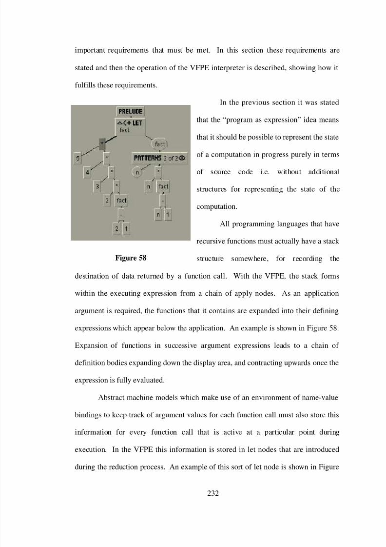
7/31/2019 Visual Fp Environment
http://slidepdf.com/reader/full/visual-fp-environment 242/312
important requirements that must be met. In this section these requirements are
stated and then the operation of the VFPE interpreter is described, showing how it
fulfills these requirements.
In the previous section it was stated
that the “program as expression” idea means
that it should be possible to represent the state
of a computation in progress purely in terms
of source code i.e. without additional
structures for representing the state of the
computation.
All programming languages that have
recursive functions must actually have a stack
structure somewhere, for recording the
destination of data returned by a function call. With the VFPE, the stack forms
within the executing expression from a chain of apply nodes. As an application
argument is required, the functions that it contains are expanded into their defining
expressions which appear below the application. An example is shown in Figure 58.
Expansion of functions in successive argument expressions leads to a chain of
definition bodies expanding down the display area, and contracting upwards once the
expression is fully evaluated.
Abstract machine models which make use of an environment of name-value
bindings to keep track of argument values for each function call must also store this
information for every function call that is active at a particular point during
execution. In the VFPE this information is stored in let nodes that are introduced
during the reduction process. An example of this sort of let node is shown in Figure
232
Figure 58

7/31/2019 Visual Fp Environment
http://slidepdf.com/reader/full/visual-fp-environment 243/312
59. Once introduced, these let expressions
identical to ordinary let expressions with the
exception that they disappear automatically once
they become redundant (i.e. once all their
variables disappear from the program). The
stepwise reduction execution method does not
have an equivalent to a “program counter”, which
is the other major piece of execution state in
imperative program execution. Each reduction
cycle incorporates the process of locating the next active redex: the only information
needed to start the reduction cycle is the location of the node (expression) to be
executed. In the VFPE this is simply the currently selected node.
Another important requirement of the interpreter is that it display reduction
steps of the right granularity. Each interpreter step displays a snapshot of the
executing program, and it is important that this sequence of snapshots conveys the
information required by the programmer. There are two opposite dangers here. One
is that if the individual reduction steps are too coarsely grained then some important
operation that needs to be recognised and understood is obscured by other operations
with which it is conglomerated. The other danger is that if individual reduction steps
are too finely grained, then it either takes too long to step through to an important
operation, or that an important operation is spread over too many small steps and is
difficult to recognise. On one hand we do not want to drown in detail; on the other
hand we do not want to throw the baby out with the bath-water.
The VFPE tackles this dilemma by ensuring that the very smallest
meaningful reduction step can be displayed, but to aggregate these atomic reduction
233
Figure 59

7/31/2019 Visual Fp Environment
http://slidepdf.com/reader/full/visual-fp-environment 244/312
steps into interpreter steps in flexible and useful ways. By making the indivisible
reduction steps as small as possible we ensure that no significant computation step
“slips through the cracks” to be hidden in the workings of the interpreter. By
aggregating reduction steps the interpreter is able to “fast forward” though
uninteresting detail and move the execution forward in meaningful increments.
In order to expose the detailed workings of a computation, nothing that could
be of importance can be hidden or abbreviated. To ensure this, the reduction engine
performs only a fixed amount of work with each reduction step. It does not perform
any reduction steps which could be decomposed into simpler operations; most
especially, it does not invoke itself recursively. Working with simple execution steps
also has the advantage of requiring only simple layout changes for each step, which
makes implementation simple and aids the coherence of the programmer’s mental
model of the program. It also precludes the possibility of the interpreter getting
stuck in a loop: any program non-termination will show up as a cycle of repeated
reduction steps, not as a frozen interpreter.
An apt term for the process of abridging the sequence of reduction steps in
order to concentrate the useful information is “temporal filtering”, used in [Foubis
95].95 The VFPE implements three different temporal filters. The first is, quite
simply, the ability to choose any sub-expression and reduce it fully. If the
programmer knows (or suspects) that an interesting part of the execution takes place
on a particular branch of the computation, then that branch can be evaluated
independently of the larger expression. This technique can be applied successively
to the expanding program, allowing the programmer to zero in on an interesting part
95 The complementary term “spatial filtering” refers to the visual abbreviation of a single
program tree.
234

7/31/2019 Visual Fp Environment
http://slidepdf.com/reader/full/visual-fp-environment 245/312
of the computation. Note that picking and choosing amongst redexes in order to
guide the debugging execution process is perfectly safe in terms of the computation’s
final value. In a purely functional language, it is guaranteed that the result of the
computation is independent of the order in which redexes are evaluated.
The second temporal filter is the ability to set breakpoints on any definition
(see section 4.1.4). This is a staple of any debugging system, allowing execution to
be suspended whenever a particular definition becomes active.
The third temporal filter is the ability to execute a specified number of atomic
reduction steps, allowing an computation to be periodically interrupted. This feature
has several uses. One is as insurance against non-terminating computation: the
progress of a long-lived computation can be inspected to see if it is making headway.
Another use is for periodically sampling a computation in order to give an overview
of an algorithm’s behavior.
A fourth filter (not implemented) would be the ability to optionally
incorporate some or all of the de-sugaring reduction steps into a nearby (i.e. previous
or subsequent) “more significant” reduction step. The de-sugaring reductions are
necessary for the operation of the interpreter, but might be an unnecessary distraction
for the programmer.
235

7/31/2019 Visual Fp Environment
http://slidepdf.com/reader/full/visual-fp-environment 246/312
8.3 Reduction Algorithm
In this section an algorithm for performing a single source-level reduction
step for a visual functional program is given. The cumulative effect of applying the
algorithm to a program sub-expression is to reduce that expression to normal form
i.e. to execute the expression. The algorithm and issues arising from it are discussed
in the form of an annotation of the algorithm (the algorithm steps are numbered for
clear reference).
Before the annotation begins some general comments are in order. Where
Reduce appears to be invoked recursively, the invocations are actually jumps (with
a re-setting of the expression to be reduced), not procedure calls. Reduce always
terminates, it does not return to the statement after the invocation. The
PatternMatch sub-algorithm either terminates by jumping back to Reduce, or
returns a Boolean value to the invoking expression. The algorithm could have been
expressed in strict functional or procedural style, but the flow-control style is clearer
than either.
Reduction Algorithm Reduce
Given a program containing an expression to be reduced E, and reduction
semantics settings:
reduction order , NOR (normal order) or AOR (applicative order);
call type, call-by-need or call-by-value;
strict constructors, true or false;
expand cycles, true or false;
the algorithm either (a) succeeds by altering the program to perform a single
reduction step, (b) succeeds by detecting that the program is in normal form, or (c)
detects a program error (e.g. a pattern-set fall-through). The notation Reduce(X) is
shorthand for “E ← X; goto reduce expression” .
236

7/31/2019 Visual Fp Environment
http://slidepdf.com/reader/full/visual-fp-environment 247/312
Visited← ∅ 0
label: reduce expression 1
switch flavour(E) of 2
caseVar:
3
if E is λ-bound 4
fail: evaluating λ-bound variable 5
CycleExpansion← false 6
if E ∈ Visited 7
if expand cycles 8
CycleExpansion← true 9
else 10
fail: non-termination 11
Visited← Visited∪ {E} 12
B ← binding(E) 13PB ← binding at root of B 14
while PB ≠ B 15
PE← part of definition body corresponding to PB 16
if PE is in normal form 17
if PE is Let 18
promote bindings of PE to LE 19
succeed: promote let bindings 20
if function(PE) does not match PB 21
fail: pattern mismatch in Let binding 22
PB←
next binding on path to B23
else PE is not in normal form 24
Reduce(PE) 25
VE ← part of definition body corresponding to B 25
if VE is in normal form or CycleExpansion 26
replace E with copy of VE 27
succeed: unfolded variable 28
else 29
Reduce(VE) 30
case Placeholder: 31
fail: evaluating placeholder 32
case Conditional: 33
if condition(E) is in normal form 34
if condition(ground(E)) 35
replace E with consequent(E) 36
succeed: chose consequent 37
else 38
replace E with alternative(E) 39
succeed: chose alternative 40
Reduce(condition(E)) 41
case Guards: 42
237

7/31/2019 Visual Fp Environment
http://slidepdf.com/reader/full/visual-fp-environment 248/312
(C,V) ← first guard/value pair of E 43
if C is in normal form 44
if ground(C) 45
replace E with V 46
succeed: guard match 47
else not C 48 if (C,V) is last guard/value pair 49
fail: guard fall-through 50
else 51
remove (C,V) from guard 52
succeed: guard mismatch 53
else C is not in normal form 54
Reduce(C) 55
case Let, Datatype: 56
if E has no bindings 57
replace E with body(E) 58
succeed: removed empty Let 59
else 60
Reduce(body(E)) 61
case List: 62
CL ← make constructor function version of E 63
replace E with CL 64
succeed: list to cons form 65
case Apply: 66
F ← function(E) 67
if F is a Let 68
promote Let 69 succeed: promoted Let 70
(F,Args) ← search down spine for function collecting arguments 71
if F is a constructor function 72
if not strict constructors or length(Args) < arity(F) 73
succeed: normal form 74
if reduction order is AOR and if some Arg not in normal form 75
Reduce(non-normal Arg) 76
if F is not in normal form 80
Reduce(F) 81
if length(Args) is < arity(F) 82 succeed: in normal form 83
if F is built-in 84
ApplyPrimitive(F,E) 85
if F is constructor function 86
succeed: in normal form 87
if F is a Pattern-Set 88
L ← first LambdaAbs of F 89
if not PatternMatch(bindings(L),Args) 90
if A is last LambdaAbs of F 91
238

7/31/2019 Visual Fp Environment
http://slidepdf.com/reader/full/visual-fp-environment 249/312
fail: pattern-set fall-through 92
else 93
remove first A from F 94
succeed: pattern mismatch 95
goto perform beta reduction 96
if F is LambdaAbs 97L ← F 98
if not PatternMatch(bindings(L),Args) 99
fail: lambda-pattern mismatch 100
label: perform beta reduction 101
if call type is call-by-need 102
Env ← new LetAbs(body(L),bindings of L, Args) 103
replace E by Env 104
else 105
for each binding B in L 106for each variable V for binding B 107
replace V with copy of argument in Args corresponding to B 108replace E with body of L 109
succeed: beta reduction 110
fail: bad function node 111
default: 112
succeed: in normal form 113
The PatternMatch procedure is part of Reduce, it is listed separately for clarity.
The procedure determines whether or not the list of pattern expressions BS match the
list of specified argument value expressions Args, performing reduction operations
on value expressions as necessary. PatternMatch can either terminate (terminating
the entire Reduce procedure) by performing a program reduction or detecting a
program error; or returns to the part of the reduce procedure that invoked it
indicating whether or not the pattern matches the arguments.
foreach B in BS 114
A ← argument value corresponding to B 115 if B is VariableBinding 116
continue 117
if A is not in normal form 118
Reduce(A) 119
if B is LiteralBinding 120
if literal ground(A) matches literal binding B 121
continue 122
else literal mismatch 123
return false 134
239

7/31/2019 Visual Fp Environment
http://slidepdf.com/reader/full/visual-fp-environment 250/312
if B is ConstructorBinding 125
if constructor function of ground(A) matches constructor binding B 126
if PatternMatch(children(B),arguments of application(A)) 127
continue 128
else mismatch in argument matching 129
return false 130 else constructor function mismatch 131
return false 132
return true 133
8.3.1 Reduction Algorithm Annotation
Outline (2). At the top level, the algorithm is a switch governed by the
expression’s flavour and whether its constituent parts are in normal form. Glossing
over the details it can be described thus:
• Placeholders and λ-bound variables constitute a program error;
• Let-bound variables either have their defining expression reduced, or are
replaced with a copy of the definition;
• Conditional expressions reduce the condition, or are replaced with the
appropriate branch;
• function applications reduce the function (and possibly the arguments,
depending on the semantics), or perform a λ-calculus reduction step
(primitive function or beta-reduction);
• Otherwise the expression is in normal form.
Definition cycles (0,6-12,26). When a variable is encountered and its
definition is not in normal form, the definition is reduced. Whenever this occurs, the
variable’s binding is remembered in the Visited set. If the same variable is
encountered again, this is a sufficient condition to determine that the program being
240

7/31/2019 Visual Fp Environment
http://slidepdf.com/reader/full/visual-fp-environment 251/312
reduced is non-terminating, so the reduction algorithm terminates and reports this
fact. Apart from the reduction of variable definitions, branches back to the main
label always move E down the tree. This fact, along with the maintenance of the
Visited set, guarantees that the Reduce algorithm terminates.
For illustrative purposes, this feature can be switched off with the expand
cycles.
λ-bound variables (4,5). This case (attempts to evaluate a λ-bound variable)
does not occur in an ordinary interpreter, since λ-bound variables always occur in the
body of a λ-abstraction, which is already in normal form. It needs to be dealt with in
the VFPE because programmers can select any node in the program for reduction,
even those inside expressions in normal form.
Let constructor patterns (13-25). The existence of constructor patterns
complicates the evaluation of variables. The basic reduction step is to reduce the
definition of the variable to normal form and then replace the variable with the
definition. If the variable’s binding is part of a constructor pattern, then it is first
necessary to reduce enough of the expression containing the definition before the
definition is reduced. This is done by starting at the root of the definition expression
and proceeding down the expression (which must be a series of constructor function
applications since the program is type correct) until the sub-expression
corresponding to the variable’s binding is reached. Figure 60 shows an example of a
reduction step of this kind.
241

7/31/2019 Visual Fp Environment
http://slidepdf.com/reader/full/visual-fp-environment 252/312
Normal form tests (17, et
al). At several points in the
algorithm a test is made so see if
some expression is in (weak head)
normal form. We have not written
down the algorithm for this, since
it has virtually the same structure
as reduction algorithm. To test
whether an expression is in normal
form, the reduction algorithm is
executed right up to its final step.
If the step would succeed with a
reduction step the test returns
false; if it succeeds and reports the
expression in normal form the test returns true; if it fails then the main algorithm
fails in the same manner. Since the action upon determining that an expression is not
in normal form is usually to go ahead and reduce the expression, the actual
implementation avoids doing the work twice by going ahead and attempting the
reduction during the test, and catching the case where the expression is in normal
form.
Let promotion (18-20). This case is necessitated by the way let expressions
and applications are reduced. It was stated previously that the expression defining
the body of constructor pattern binding must consist (when reduced to normal form)
of applications of data constructor functions. Actually, these applications can have
let abstractions sandwiched between them. Since the lower parts of these
242
Figure 60

7/31/2019 Visual Fp Environment
http://slidepdf.com/reader/full/visual-fp-environment 253/312
expressions are duplicated and copied to the site of the variable, bindings that appear
in these let abstractions need to be “promoted” up to the main let abstraction. If this
were not done then variables for these bindings would escape from their binding’s
scope when the copy was made. Figure 61 shows a binding (‘x’) being promoted
upwards in this fashion.
In the VFPE the binding promotion
operation is always safe. That is, moving a let
binding upwards to an enclosing let abstraction
never invalidates a program. Upwards motion of
a binding never decreases the binding’s scope, so
its variables will never be orphaned; and because
the relationship between variables and bindings is
kept by internal pointers and not by textual names,
the promoted binding never “captures” another
binding’s variables even if they happen to have
the same name.
Breakpoints (28,85). If this variable’s
binding has been marked as a breakpoint, this fact
is flagged along with the successful termination. In the case that Reduce is being
applied repeatedly to reduce an expression to normal form, this signals that execution
has encountered a breakpoint and should be halted.
Breakpoints can also be set on primitive functions.
Placeholders (31). The VFPE interpreter allows the execution of incomplete
programs. Provided that the reduction sequence does not cause the evaluation of a
243
Figure 61

7/31/2019 Visual Fp Environment
http://slidepdf.com/reader/full/visual-fp-environment 254/312
placeholder node (e.g. it lies on a branch of a conditional or guarded expression that
is not selected, or is an unused function argument in normal-order reduction mode),
the presence of placeholders does not affect execution. It is usually desirable to
explicitly indicate any undefined cases in an algorithm: in this context placeholders
play the role of an execution-halting error function that is provided in most
functional languages.
Ground values (34,45,121,126). Wherever the algorithm must examine a
sub-expression in normal form in order to proceed (in the conditional expression
types and in pattern matching), the notation “ground(E)” indicates that the algorithm
should look past any intervening let definitions by following the let body spine until
the required literal is found. The program’s type correctness ensures that it will be
present.
Guards (42-55). Since the evaluation of a guard-set conditional expression
involves evaluating each guard in turn, the program must in some way record which
guards have been tested, so that subsequent reduction cycles resume evaluation in the
right place. A simple way of doing this is to always work on the first guard in the
list, and to remove the first guards from the list if the test fails. In a purely functional
language the value of an expression is immutable, so once it is determined that a
guard expression evaluates to false it will always be false and the guard expression
(and its corresponding consequent expression) can be removed from the program,
since neither will take part in further evaluation.
Environment clean-up (57-59). At this point it is possible to insert a
reduction step that, while computationally expensive, results in more comprehensible
programs. Let expressions that are created by call-by-need beta reduction (see 90-
92) are specially marked. Whenever such a let expression is encountered, a
244

7/31/2019 Visual Fp Environment
http://slidepdf.com/reader/full/visual-fp-environment 255/312
dependency analysis can be done to check whether any of its bindings are referred to
in the let body value (either directly, or through a dependency chain). If there are
bindings for which there are no outstanding variables, the bindings can be removed.
The inclusion of this reduction step results in environment let expressions being
cleaned up as soon as they become redundant. Initial experience with the interpreter
shows that this makes a significant improvement in the comprehensibility of
executing programs.
Lists (63-65). Normal form for expressions with a constructor types
(including lists) is an application of a constructor
function. Since the interpreter (in particular, the
pattern-matching mechanism) requires expressions
to be in this normal form, a de-sugaring step to
convert list flavoured expressions into constructor
function application form takes effect whenever a list node is encountered.
Let promotion on application spine (68-70). Let abstractions that occur on
the spine (the left-hand chain branch of a chain of apply nodes) of an application are
made to percolate upwards until the spine is free from let nodes. An example of this
reduction step is shown in Figure 62. The reason for this is similar to that noted for
step 18: when the head application node is replaced by the result of a reduction step,
any bindings of let abstractions existing on the spine would be lost, possibly
orphaning variables.
Argument collection (71). This is really just an administrative step, to give
algorithm variable names (F and Args) to parts of the expression. Proceeding down
the left-hand branch of the application spine, all the non-leftmost branches are added
to the Args collection; F is the first non-Application node encountered on the spine.
245
Figure 62

7/31/2019 Visual Fp Environment
http://slidepdf.com/reader/full/visual-fp-environment 256/312
This step deals with the fact that due to currying, function arguments may be spread
across several different apply nodes.
Constructor functions (72-74, 86-87).. The VFPE allows both strict and
non-strict constructor functions. Non-strict constructor functions allow the
manipulation of potentially infinite data structures in otherwise strict languages (e.g.
the standard implementation of Hope [Perry 87]).
Partial application (82). At this point the function F will be a function
expression (guaranteed by the program’s type correctness) and will be in normal
form (guaranteed by the previous steps). Since F is either a primitive function, λ-
abstraction or pattern-set it is assumed that the arity of F is immediately available.
Primitive functions (85). It is assumed that each primitive function has its
own reduction algorithm, each of which can terminate in the same ways as Reduce
and conform to the same single-stepping behavior. The primitive reduction
algorithms typically make use of Reduce to ensure that one or more of their
arguments are in normal form, and replace the whole application expression (E) with
the result of the primitive function computation.
Pattern sets (88-95). Pattern sets operate in a similar fashion to guard-set
expressions. The pattern-set’s first λ-abstraction is matched against the arguments
using the PatternMatch procedure. If the match succeeds, execution proceeds as if
the pattern-set were actually the λ-abstraction. If it fails, the abstraction is removed
from the pattern-set.
Call-by-need (102-104). Call-by-need semantics are implemented by
creating a new environment with binding for each λ-binding/argument expression
246

7/31/2019 Visual Fp Environment
http://slidepdf.com/reader/full/visual-fp-environment 257/312
pair. The beta reduction is performed by converting the λ-abstraction body into a let
abstraction (with the application arguments becoming each binding’s defining
expression), and replacing the application with the new let abstraction..
When a variable value is needed the reduction rules for variables (3-30) take
effect and reduce the definition body of the variable before copying the argument
value, ensuring that the work is shared with subsequent evaluations of the variable.
Since VFPE programs remain strictly tree structured, call-by-need semantics
cannot be implemented via graph reduction. In a graph-reduction implementation
each variable participating in the beta-reduction is replaced by a pointer to a
(possibly shared) argument expression. Any reduction work done on the argument is
shared as the expression is updated with its reduced value. The VFPE semantics are
not quite the same, in that if the reduced argument body contains any redexes
(“beneath” the weak head normal form) and these redexes are reduced, this work is
not shared, since the argument is copied once it is in normal form: the VFPE thus
does not implement so-called “full-laziness” (as defined in e.g. [Field 88]).
“Lazy” semantics in functional languages is commonly defined as the
combination of call-by-need and normal-order reduction, while “strict” (or “eager”)
semantics refers to call-by-value and applicative-order reduction. Although the other
combinations of reduction order and call type are not normally seen96 the VFPE
allows them anyway: they may be of some educational use.
Call-by-value (106-109). Call-by-value reduction is implemented by simply
locating each participating variable and replacing it with a copy of the corresponding
application argument. These updates have been written as a single reduction step,
96 With AOR and call-by-need, creation of the environment to share reduction work is
redundant, since each argument is fully reduced already; NOR and call-by-value potentially creates
copies of argument expressions which are not in normal form, duplicating work.
247

7/31/2019 Visual Fp Environment
http://slidepdf.com/reader/full/visual-fp-environment 258/312
which could be considered to be breaking the
“single program modification” principle of
the interpreter. As an alternative, the body
expression could be searched and a single
variable replaced on each cycle (with the
final replacement of the application being
performed when no more variables remain in
the λ-body). Figure 63 contrasts the
reduction of a beta-redex in call-by-need and
call-by-value modes.
111. This step should never be reached in a correct program since the only
expressions which can have a function type (apart from the body of a let expression)
are constructor functions, primitives, pattern-sets and λ-abstractions.
Normal form syntax (113). The remaining expression flavours are λ-
abstractions, pattern-sets, primitive functions and literals, which are in normal form.
Pattern matching (114-133). The basic operation of the PatternMatch
routine is to examine each binding/value expression pair in turn looking for either (a)
reduction work required to match the pair, or (b) for a pattern mismatch. If all pairs
match then success is reported, otherwise pattern match failure or a reduction step is
indicated. Pattern matching is performed left-to-right and terminates prematurely if a
match failure is detected.
Many of the different sorts of reduction steps can be seen in the example
applets which demonstrate the interpreter (the “Reduction order”, “Lazy
248
Figure 63

7/31/2019 Visual Fp Environment
http://slidepdf.com/reader/full/visual-fp-environment 259/312
constructors” and “Tail recursion” applets). Perhaps the best way of clarifying the
individual step operations is to run the VFPE, construct a case one is interested in,
and single step through it.
8.4 Interpreter Controls
Operation of the VFPE
interpreter is quite simple.
Reduction is triggered by first
selecting a value node, and then
pressing either of the single-step or
reduce-to-normal-form buttons on
the control panel at the top of the
main application window (or by
using the control - r and control - e
key shortcuts). The interpreter
either reports that the expression is
in normal form, reports a program error, or replaces the selected node with the
reduced expression (and selects the root of this expression so that the single-step
button can be pressed repeatedly). Reduction can also be triggered from the value
node’s control panel.
The interpreter’s other features are controlled from a reduction control panel
(Figure 64), which can be summoned by pressing a button on the main control panel.
This control panel has two main sections. The upper section contains controls for
selecting reduction semantics, while the lower section shows accumulated profiling
statistics.
249
Figure 64

7/31/2019 Visual Fp Environment
http://slidepdf.com/reader/full/visual-fp-environment 260/312
In the upper section, check-boxes allow the programmer to choose reduction
order (applicative order verses normal order), function call type (call-by-value verses
call-by-name) and constructor function semantics (strict verses lazy constructors).
Section 8.3.1 describes the effects of each of these settings. The panel also contains
a control for setting the reduction count limit.
The lower section of the reduction control panel shows execution profile
information. The VFPE interpreter maintains a very simple collection of profile
data: it records the number of times a variable with a particular name is instantiated.
While rather unsophisticated, this mechanism is useful enough for verifying (or
falsifying) a programmer’s expectations about relative numbers of function
invocations, and for performance comparisons between algorithms.
Breakpoints are set and cleared from the node control panel of the
definition’s binding syntax node.
250

7/31/2019 Visual Fp Environment
http://slidepdf.com/reader/full/visual-fp-environment 261/312
9. Interpreter Examples
This chapter offers concrete examples of the VFPE in operation, and is
intended to be read in conjunction with the example applets, slideshows and
programs that accompany this thesis. This chapter has two main purposes.
Firstly, these examples act as a visual tutorial on the operation of the
interpreter, complementing the text and images in this document.
Secondly, the examples are presented to offer some evidence for the
assertions (made in the previous chapter) that the VFPE’s interpreter may be useful
for demonstrating functional program reduction concepts; for algorithm animation;
and for simple profiling. None of these examples are pursued here to great length:
the idea rather is to present a sample of the kind of things that the VFPE visual
editor/interpreter combination makes possible.
9.1 Reduction Examples
The first pair of examples introduce the general operation of the interpreter,
and make use of the interpreter’s incremental reduction capability to illustrate the
evaluation of an expression under two alternative reduction settings.
The “Reduction order” example applet should be viewed at this point.
The salient features of the first example applet are:
• the use of the interpreter control panel to change reduction strategy settings,
• a simple reduction sequence involving the application of both user defined
and primitive functions,
251

7/31/2019 Visual Fp Environment
http://slidepdf.com/reader/full/visual-fp-environment 262/312
• reduction at the finest level of execution granularity: each single-step
operation corresponds to one application of the reduction algorithm
described in the previous chapter, and makes a single alteration to the
program, and
• the contrast between normal-order and applicative-order reduction
strategies.
The “Lazy constructors” example applet should be viewed here.
Interesting features of the second example applet include:
• the creation and duplication of a test expression,
• the use of the “evaluate to normal form” operation,
• the ability to reduce arbitrary sub-expressions in a program, not just at the
site originally constructed for testing, and
• the contrast between strict and lazy constructor function reduction
strategies.
9.2 Algorithm Animation
The next set of examples demonstrates the use of breakpoints for stepping
though a program. The examples show that with the judicious placement of
breakpoints, and for reasonably small programs, the VFPE interpreter can be used to
exhibit a form of algorithm animation.
252

7/31/2019 Visual Fp Environment
http://slidepdf.com/reader/full/visual-fp-environment 263/312
The “Tail recursion” example applet, and the “Tree insertion algorithm
animation” and “Sorting algorithm animation” slideshows a should be viewed here.
9.3 Profiling
The next set of examples show how the count of reduction operations can be
used to investigate the efficiency of different functional algorithms. While the
reduction count is not calibrated against any model of compiled program
performance, it is sufficient to examine the abstract algorithmic complexity of
different algorithms.
The “Sorting profiling” example slideshow should be viewed at this point.
This kind of simple profiling is by no means novel (being inspired by e.g. the
HUGS interpreter). What is interesting is the ease with which test code can be
manipulated; and, as will be seen in the next section, how the ongoing reduction
process can be explored interactively.
9.4 Simulating Parallel Reduction
Another interesting feature of the interpreter is that it can be used (in a rather
crude way) to gauge the potential for parallel execution of a program. The ability to
select different sub-expressions of a single program and evaluated then
independently provides a measure of how much reduction “work” exists in different
parts of an executing algorithm.
253

7/31/2019 Visual Fp Environment
http://slidepdf.com/reader/full/visual-fp-environment 264/312
The “Quicksort parallelism profiling” example slideshow should be viewed
here.
The VFPE includes a simple parallel reduction simulator, based on the idea
of expressing parallel computations through parallel functional skeletons. This
functional programming approach to specifying parallel computations is described in
[Darlin 95]. In summary, the idea is to express a parallel algorithm in terms a fixed
set of primitive parallel operators, each of which has (a) precise semantics (expressed
in terms of the source language) and (b) a compilation path to some piece of parallel
hardware upon which it can be efficiently implemented.
The VFPE provides a single primitive parallel operator, the parallel tuple.
Essentially, this is a parallel version of the ordinary tuple constructor function,
except that each element is conceptually reduced in parallel. After trying several
alternative parallel primitive sets (including arbitrary length parallel arrays, and
parallel tuples implemented via a built-in function library), it was felt that including
parallel tuples as a primitive syntactic type was more illuminating.97 A syntactic and
operational description of this expression flavour is included in section 11.1; it was
not included earlier because, unlike the other elements of the VFPE syntax, it is not a
widely understood or implemented part of existing functional programming
languages, and can be safely ignored outside the present section.
The performance model of the parallel tuple is very simple: the number of
reduction steps needed to evaluate the tuple to normal form is the maximum of the
number of reduction steps needed to bring each element of the tuple to normal form.
97 By making use of the existing (sequential) interpreter machinery, adding different
simulated parallel reduction models turns out to be easy.
254

7/31/2019 Visual Fp Environment
http://slidepdf.com/reader/full/visual-fp-environment 265/312
The “Parallel quicksort” example slideshow should be viewed here.
The relative ease in which the VFPE interpreter has been pressed into the
various uses described in this chapter is encouraging. At the outset of the interpreter
development, little specific thought was given to these applications. The thought
was rather to start with the idea that the program is the computation state (inherent in
the λ-calculus computational model) and make this idea clear by means of a source-
level interpreter for the visual functional syntax. Once this goal was achieved,
several interesting new uses for the VFPE seemed to occur naturally.
255

7/31/2019 Visual Fp Environment
http://slidepdf.com/reader/full/visual-fp-environment 266/312
10.Conclusions and Further Research Directions
10.1 Novel Contributions
This thesis makes several novel contributions to the understanding and
practice of programming environment development. These are summarised below in
rough order of significance.
The identification of functional language value expressions as a useful
basis for a visual programming environment. Although this is a simple idea, the
success of a visual editing environment depends on the selection of a practical set of
objects to represent the problem domain, so its importance should not be overlooked.
Functional value expressions are both simple, since as a class functional expressions
can all be manipulated in the same way (for drag-and-drop editing, external storage,
type queries, and execution), yet contain sufficient internal complexity (though the
various expression flavours and hierarchical structure) to encode a general-purpose
programming language. As stated in Chapter 3, this thesis can be read as an
exposition of this idea.
The incremental type inference algorithm and the availability of type
information to the programmer. Major goals of the VFPE project were to produce
a programming environment that offered instant feedback on static (type and syntax)
programming errors; and to make as much type information as possible easily
accessible to the programmer, as an aid to program construction and comprehension.
The major challenge in implementing these goals is the timely provision of
type information to the programmer. The simple expedient of performing a complete
program type-check with every editing operation is too slow: the VFPE includes an
256

7/31/2019 Visual Fp Environment
http://slidepdf.com/reader/full/visual-fp-environment 267/312
optimisation for the most common types of editing operations, which provides
adequate performance.
Of course, if the continued advance in hardware performance persists to a
point where the time taken to completely type-check a module from scratch becomes
inconsequential compared to human reaction time, then the need for optimisations
becomes moot. Until then, and because the idea of incremental type checking is
interesting in itself, such optimisations are worthwhile objects of study.
The single-step source level interpretation of visual functional programs.
Single-stepping source level execution, and visual display of executing functional
programs have both been demonstrated before. We believe, however, their
successful combination, and their integration with a visual editing environment, is
new in the VFPE. Although the VFPE interpreter does not present a fundamentally
new functional program execution model (being based on functional language
compilation techniques and term-rewriting λ-calculus implementations), a stepwise
interpretation algorithm that incorporates stateless execution (i.e. requires no stack or
environment external to the expression being reduced), which executes pattern-
matching directly, and which allows for several different reduction semantics, has
not been described in detail before.
We believe that the close integration of the interpreter and the editing
environment allows an unprecedented flexibility in the testing and tracing of
functional programs. The ability to quickly build expressions, and then to copy and
manipulate them; and the ability to direct a sequence of reductions “by hand” (as
well as by the use of breakpoints) enables techniques that are laborious and/or
257

7/31/2019 Visual Fp Environment
http://slidepdf.com/reader/full/visual-fp-environment 268/312
impossible in a conventional execution environment. The practical value of these
techniques is unknown.
The visual syntax itself. The VFPE visual syntax is an evolutionary
development of the de-facto standard for tree representations of functional programs.
Its major innovations are its depiction of pattern-matching structures (i.e. the set of
visually distinct but corresponding tree representations for both bindings and value
expressions) and the various decorations added to nodes to enable space-efficient
display. The rationale behind the selection of categories of objects for visual
manipulation (e.g. functional value and binding expressions, but not type expressions
or function definitions), and the rationale for selecting a tree representation (ahead of
a nested box representation, or the use of acyclic or cyclic graphs), although
presumably implicit in other systems that render functional programs as trees, is
articulated in detail here.
10.2 Future Research Directions
Even though he is excited by the idea of radically new and powerful forms of
program representation and manipulation, the author admits that he has very little
idea about where to begin in designing and testing them. On the other hand, several
clear directions for future research stem from this project.
10.2.1 Measurement of Visual Programming Environment Operation
Perhaps the greatest shortcoming of this thesis is the lack of diverse testing of
the VFPE. While we contend that the VFPE is a useful tool (and could be made
more so), we have been scrupulous in avoiding statements to the effect that the VFPE
is superior to textual programming environments or other visual programming
258

7/31/2019 Visual Fp Environment
http://slidepdf.com/reader/full/visual-fp-environment 269/312
environments. While we suspect for many purposes and situations (for novice
programmers, for example) that this is the case, we have no measurable evidence
either way. To produce truly significant results, experiments to perform this kind of
evaluation should be carefully prepared and use a large a sample of programmers as
possible. Section 11.3 contains an outline for such an experiment.
On a different tack, having a sizable body of visual code for analysis (such as
that generated by user experimentation), would allow an examination of how visual
programming effects the design and coding style of programmers. Do they change
the granularity of their introduction of local definitions ? Do they use more or less
higher-order functions ? Do they use more combinators and less variables, or vise
versa ? Such analysis might provide insight into the thought processes of
programmers, and might help guide the development of new flavours of visual
syntax.
10.2.2 “Visual Haskell”
The current implementation of the VFPE falls short of being an “industrial
strength” programming environment in several areas. The VFPE has been tested
with (and performs adequately for) some small, and a few medium-sized programs.
To successfully handle larger and more diverse programs the VFPE needs to be
expanded upon in several ways. We have dubbed the imaginary result of this
expansion work “Visual Haskell”, although like the VFPE it need not be tied to any
particular existing functional language.
Improved program layout. The VFPE layout system struggles with large
expressions. This is especially true of expressions generated during lengthy
259

7/31/2019 Visual Fp Environment
http://slidepdf.com/reader/full/visual-fp-environment 270/312
computations.98 The shortcomings of the current implementation become apparent
during the execution of large, recursive programs. These build up large program
trees that the system is hard pressed to render quickly. There are at least four
avenues for improvement in program layout.
The first is simply an optimised re-write: the current implementation suffers
from its experimental heritage, containing unused features and a rather evolutionary
architecture. For instance the VFPE allows syntax nodes to be re-positioned by the
programmer, a feature considered and rejected.
Secondly, there is much scope for layout “spatial filtering” in order to make
the most of limited display space. Examples of techniques for showing a condensed
view of large expressions might include “abbreviation” nodes that collapse stable
sections (i.e. sections that remain unchanging throughout many editing or reduction
steps) of the program tree to a single node; or certain types of “skeletal” program
layout (e.g. show only non-library functions, show only let-nodes etc.).
Thirdly, the existing VFPE syntax flavours are very much a first cut at
choosing a set of visual syntactic operators. There are almost certainly new syntax
flavours, or alternative layouts of existing flavours, that are more comprehensible
and/or make better use of layout space. For example, it might be advantageous to
relax the “draw sub-expressions in a line below the parent” layout rule scheme for
some flavours, and render particular sub-expressions in different locations or in
different directions.
98 And, presumably, code generated by a programming style that favors large expressions.
Visual expressions that take up several pages of layout space correspond to long multi-line (and
difficult to comprehend) textual expressions, and it could be argued that this is bad programming
style and should not be encouraged. It could also be argued that visual expressions might not suffer
the same comprehensibility problems and that new programming styles should be allowed, at least
for experimentation purposes.
260

7/31/2019 Visual Fp Environment
http://slidepdf.com/reader/full/visual-fp-environment 271/312
Fourthly, it would be interesting to explore the use of high-resolution displays
backed by powerful processors to show a single “continuous” view of a program at
various levels of magnification, rather than the VFPE approach of dividing up a
program tree according to let-definitions and showing parts in separate windows.
Interpreter development. Compared to some proposed functional language
execution tracing techniques (e.g. those described in section 2.6) the VFPE
interpreter is rather simple. Since the VFPE interpreter seems to be quite adaptable,
it might be possible to implement some more sophisticated debugging techniques in
the VFPE. Alternatively, some of the VFPE visualisation and editing ideas could be
used to complement other systems.
Textual code import and export. The ability to import from and export to
existing functional languages would probably do more to make the VFPE a serious
industrial tool than anything else. Textual import would allow the VFPE to be
immediately pressed into service on “real-world” sized projects, while improved
textual output (perhaps with the ability to automatically trigger external compilation
and linking) would allow end-to-end development with the VFPE.
Modules. A more flexible system for permanently recording visual
functional programs is needed. The ability to declare set of services for export, and
conversely to import services in the absence of a their implementation, is a vital
feature for partitioning of large projects into manageable pieces, and for the
development of re-usable code. A textual code import/export mechanism could be
used for this purpose, but this would not be recording visual programs (see section
6.2). We can see two avenues of further development in this area.
261

7/31/2019 Visual Fp Environment
http://slidepdf.com/reader/full/visual-fp-environment 272/312

7/31/2019 Visual Fp Environment
http://slidepdf.com/reader/full/visual-fp-environment 273/312
the editing operations, the semantic value of the program changes, becoming either
more defined (in the case of the constructive operations) or less defined (in the case
of the “cutting” operations). The interpreter steps on the other hand (by definition)
do not alter the value of the program, but rather simplify it. There are other
meaning-preserving program transformation steps, such as inverse reduction steps,
and algebraic identities of common functions.
A program transformation tool would record (and perhaps display pictorially)
the chain of program operations executed during an session. We envisage a program
transformation session as a (possibly branching) chain of successive program states,
connected by transformations. Key states of could be cached for quick reference;
other states could be derived from these by following the transformation chain from a
cached point. The user could select and inspect any program state with the VFPE;
any transformation (editing operation, reduction step or otherwise) would create a
263
saved 10/10/2002
unfold/foo
unfold/xs
theorem/map-compose
attach/bar
attach/testlist1
reduce:unfold bar
collapsed reduction
sequence
map
compose
f g
ys
let
barbar
?
collapsed editing
sequence
Figure 65

7/31/2019 Visual Fp Environment
http://slidepdf.com/reader/full/visual-fp-environment 274/312
new linked program state. Graphical tools would be provided for storing, browsing
(e.g. collapsing long chains into single nodes) and pruning the transformation
session. Figure 65 is a speculative depiction of how this sort of transformation
session might look.
Applied as a program editor, this tool would provide all the features of the
VFPE and would additionally allow an unlimited level of undo/redo actions.
Applied to the interpreter, it would provide a tool for examining the complete record
of a reduction sequence: a powerful profiling and debugging tool. The real
motivation, though, for such a tool would be as a program proof assistant and/or
program synthesiser tool.
States linked by sequences of meaning-preserving transformations (perhaps
linked with a common colour) would constitute a proof of equivalence between the
two programs. Program proofs could be searched for by extending chains of
meaning-preserving transformations. The ability to branch off in different directions
and to backtrack to any intermediate point would be useful; what would be really
valuable would be the ability to mark off a sub-expression in a transformation chain
and have the transformation tool generalise it as a theorem or lemma, after which it
could be added as a new basic transformation step.
Functional program transformation tools and proof assistants are not new (see
e.g. [Kahl 99], [Paulso 87]). Expressions that occur in the course of function
program proofs can be both long and deep, and it seems that a visual expression
editor could be a valuable addition to such tools.
264

7/31/2019 Visual Fp Environment
http://slidepdf.com/reader/full/visual-fp-environment 275/312
10.2.4 Incremental Type Inference
We think that the VFPE type inference system raises at least three further
questions.
Firstly, are there optimisations for the “cutting” editing operations (i.e. those
that make the program less defined) ? As explained in the chapter on types, the
constructive editing operations, such as updating a placeholder node or specialising a
variable pattern, only ever narrow program types. An algorithm that performs the
narrowing (type unification) at the update site, and then chases any further induced
narrowings of let bindings, quickly restores correct program types (or determines that
no correct typing is possible). The situation with the cutting operations is different.
Replacing a sub-expression with a placeholder, for example, can cause the
placeholder site’s type to widen (i.e. become more general). Unlike the narrowing
case, this change in type invalidates the inferred types of the node’s parent
expression. It may be possible to design an algorithm analogous to the one for
constructive operations that starts at the update site and progressively re-infers only
the types affected, but our preliminary examination of the idea has yielded no
solutions.
It might be better to take a more sophisticated approach to recording type
information. Instead of simply recording a current type for each node, there might be
some way of recording the interrelationship of node types. This could serve two
purposes. It might make possible a type restoration algorithm for cut operations; it
might also enable better reporting of type errors.
A second question is: can type errors be better reported ? Although the
immediate feedback given by the VFPE greatly narrows down the cause of a type
265

7/31/2019 Visual Fp Environment
http://slidepdf.com/reader/full/visual-fp-environment 276/312
error, it is still possible that the nodes responsible for the problem are not readily
apparent. A closer coupling of the type system with the program syntax would make
possible additional feedback: colouring of the nodes most responsible for the type
error, for instance.
Thirdly, although the “type repair” algorithm was originally created as an
augmentation to the usual recursive decent type inference algorithm, we think it can
be considered as special case of a “random-order” constraint satisfaction type
inference algorithm. Such an algorithm would start with the assignment of a
different type variable to every node in the program and a set of constraints that each
node imposes on the types of connected nodes, and the algorithm would proceed by
altering the type assignments to satisfy the constraints one by one. If such an
algorithm were implemented and proven correct, the correctness of an optimised type
inference algorithm for attachment operations (where a new nodes and new
constraints are introduced) would follow immediately.
We would like to know if such an algorithm (or an equivalent algorithm) has
been described before, whether it has been proven correct, and whether it can be
applied to the incremental type inference problem posed by the VFPE.
We believe that the programming environment described in this thesis solves,
or describes the solution to, many of the practical problems with building a useful
general purpose visual programming language.
We also believe that the design of programming languages, programming
environments, and underlying computational models that are tailored both to humans
(in that they give programmers powerful ways of expressing, understanding and
transforming computations) and machines (in that they can be compiled to efficient
266

7/31/2019 Visual Fp Environment
http://slidepdf.com/reader/full/visual-fp-environment 277/312
executable code for various hardware architectures) is only beginning to be explored.
The amount, and diversity, of software that remains to be written (and, given the
state of the art, re-written) is uncertain, so the question as to which computational
models and programming languages will most effectively bridge the human/machine
interface is wide open. Perhaps textual languages of the kind commonly in use today
are powerful enough to meet the requirements of future programs. This thesis
shows, however, that programming languages need not be limited to that form.
267

7/31/2019 Visual Fp Environment
http://slidepdf.com/reader/full/visual-fp-environment 278/312
11.Appendices
11.1 Appendix: Parallel Tuple Syntax Flavour
Syntax
textual equivalent: none
node face: textual label: “parallel”
children: one or more argument value expressions
The “parallel” syntax node represents a set of
expressions that have conceptually been allocated to
different processing elements, and are to be reduced in
parallel. The type of the expression is the same as a
“tuple” data structure of the same arity.
The syntax node shows a textual label with the world “parallel” on it, and
each of the parallel tuple elements is rendered as a child expression.
Reduction
An extension to the source-level reduction algorithm, to deal with the
(simulated parallel) reduction of parallel tuple nodes, is stated below. Note that the
inclusion of simulated parallel reduction breaks the property of the interpreter that a
single reduction step makes only a single modification to the expression tree: each
parallel sub-tree that is not in normal form will be modified in a single reduction.
For this reason the recursive call-and-return invocation of the Reduce algorithm has
been make explicit, to distinguish it from the “goto” invocation that appears in the
268
Figure 66

7/31/2019 Visual Fp Environment
http://slidepdf.com/reader/full/visual-fp-environment 279/312
rest of the algorithm. It is assumed that the recursive Reduce call mutates its
argument and returns its success status.
case Parallel: 111.1
if all children are in normal form 111.2
replace E with an application of a tuple constructor of same arity 111.3
succeed: parallel decay 111.4
else 111.5
OK ← true 111.6
foreach C in non-normal form children 111.6
R ← call Reduce(C) 111.7
OK ← OK and R not a program error 111.8
if OK 111.9
succeed: parallel step 111.10 else 111.11
fail: error during parallel reduction 111.12
269
7/31/2019 Visual Fp Environment
http://slidepdf.com/reader/full/visual-fp-environment 280/312
11.2 Appendix: Program Construction Measurement Data
The data presented here was collected by instrumenting the VFPE to record
every editing and type checking operation. The method used to obtain the data was
as follows.
First, the VFPE application was instrumented to collect the data. The
modifications were of two types. Each code location that handles a successful
editing operation (data on editing errors was not collected) was modified to record
the identity of the operation. Also, the entry point to the code that performs type
checking and/or type inference was modified to record the total time spent inside the
operation, and the total size of the program (i.e. the number of syntax nodes
reachable from the root node, regardless of current node visibility).
Second, the textual test programs were selected and examined to ensure that
equivalent VFPE programs could be constructed. The two programs used, a Lisp
parser built using parser combinators, and a red-black balanced binary tree
implementation, had been written previously by the author as part of projects
unrelated to the VFPE. Although small (together they comprise about 200 lines of
Haskell) the examples are practical, working code.
Third, each program was constructed with the type inference optimisations
turned on, and both type timing and editing operation counts were recorded. During
the editing process, notes were made so that the exact sequence of operation could be
reproduced. The program constructions were then repeated from scratch with the
type inference optimisations turned off, and type timings recorded.
Lastly the data from both programs (editor operations and type timings) were
merged.
270

7/31/2019 Visual Fp Environment
http://slidepdf.com/reader/full/visual-fp-environment 281/312
The VFPE programs, and the textual programs they were based upon, can be
found on the media that should accompany this thesis. The raw type checking data
(a record for every editing operation including basic operation category, program
size and time taken in milliseconds (with 10 ms resolution), can be found in a
spreadsheet on the accompanying media. The timing information was gathered on a
1400 MHz Athlon Thunderbird CPU, 256 Mb Ram, running Windows 2000
Professional Edition, with the VFPE running on the Java 1.3.0 Windows VM.
271
basic categories
statistics category create 1069
statistics category attach 1049statistics category rename 167statistics category grow 98statistics category copy 44statistics category detach 41statistics category shrink 6
Figure 67

7/31/2019 Visual Fp Environment
http://slidepdf.com/reader/full/visual-fp-environment 282/312
other statistics
creation operations: 1069
creation of variables for user-defined bindings: 369 (35 %)creation of variables for prelude bindings: 496 (46 %)creation of built-in syntax (including literals) 204 (19 %)
creation from pallet (syntax + primitives): 700 (65%)
variables created: 865
variables created as function application: 302 (35 %)variables created without function application: 563 (65%)
uses of tool for introduction function-with-arguments let binding: 7introduction of plain let bindings: 49
272
operation counts
attach value 875create var 855
rename binding 167attach binding 156create apply 86create literal 60copy value 44grow let 41detach value 41grow pattern 28create lambda 17create let 17create pattern 8
create load 8attach empty let 8grow list 8grow guard 6shrink let 6create guard 5create list 2create datatype 1

7/31/2019 Visual Fp Environment
http://slidepdf.com/reader/full/visual-fp-environment 283/312
11.3 Appendix: Outline of an experiment for evaluating the
effectiveness of Visual Programming with the VFPE
As noted in the conclusion, the effectiveness of the VFPE as compared to a
conventional textual programming environment has not been quantitatively
evaluated. We can see two avenues for empirical evaluation of the VFPE. The first
is to conduct experiments to assess the general adequacy of the VFPE. Such
experiments would focus on showing quantitatively that for programmers already
experienced with textual languages, using the VFPE is not significantly worse than
the textual alternative. Qualitatively, these experiments could also give valuable
insight into the usability aspects of different parts of the VFPE syntax and interface.
A second avenue of experimentation would be to use the VFPE to investigate
Visual Programming. Since, in terms of semantics and abstract syntax, the VFPE
functional language is very similar to certain textual functional languages (those of
the ML family), a carefully constructed experiment should reveal differences that are
due only to the respective modes of display (textual vs. graphical tree layout) and the
programming environment tools (text editor/interpreter vs. supervising editor/source
form interpreter). This appendix outlines an experiment of the second type.
There are many possible aspects of the interaction between programmers and
visual programming environments that could be investigated. How does visual
programming change the number and type of programmer errors ? Does it change
the size and structure of code written ? Does it change the editing/testing cycle ?
Does it change the order of problem solving ? Does it lead to more or less efficient
code ? Is the resulting visual code more or less comprehensible ?
273

7/31/2019 Visual Fp Environment
http://slidepdf.com/reader/full/visual-fp-environment 284/312
The experiment outlined here focuses narrowly on the questions of the time
taken for programmers to construct solutions to a series of programming problems
and the correctness of those solutions, on the grounds that these are the most obvious
questions and the simplest to measure.
11.3.1 Preparation
It is proposed that the experiment is conducted as a part of an introductory
programming unit (or some sort of introductory computing unit with a programming
component). The idea is that the unit’s practical programming exercises and tests be
posed in VFPE and in an equivalent textual programming environment form, and
that programmer performance be measured several times during the unit by
programming tests. The focus on novice students is important, since any extensive
experience with textual programming languages will affect the learning experience,
especially if the experience is in the form of formal education where a mindset that
programs are text is formed.
The exercises themselves should be a series of increasingly complex
programming problems, broken down into progressive problem sets. The experiment
places a number of constraints on problems and the programming environments
provided for the students' use.
Firstly, a textual programming language and environment should be selected
for comparison. We suggest Haskell, and either the GHCi or HUGS interpreter
environments, primarily because the VFPE type system and syntax is based on
Haskell’s, as is the set of standard library functions. Miranda, Clean or ML would
also be suitable choices. Scheme or LISP would be less suited, because of the
274

7/31/2019 Visual Fp Environment
http://slidepdf.com/reader/full/visual-fp-environment 285/312
difference in type systems: the experiment would be in effect be testing static vs.
dynamic typing in addition to the textual vs. visual dimension.
Languages from outside the functional language family are unsuitable,
because this would introduce the functional vs. procedural dimension. Conversely,
other visual languages (e.g. Prograph) are unsuitable since this fails to compare
visual and textual languages.
Similarly, the choice of an interpreted environment approximating that of the
VFPE is important, otherwise the incremental interpreted vs. batch compiled
dimension would be introduced.
Secondly, each problem in the series needs to have equivalent textual and
VFPE forms. What we mean by this is that any example or template code provided
should exist in both forms; and for each problem it should be checked that there are
some equivalent solutions. It is not necessary for there to be a close syntactic
correspondence; but examples and solutions that use the same algorithms should
exist for both. This requirement ensures that the tasks used in the experiment are in
fact “the same” in both cases.
A third important (and quite difficult) constraint is to ensure that the material
made available to students during the course be presented in the appropriate form. In
the case where the study groups are mixed in the same course, all examples
(including small code fragments) should appear in both forms and be given equal
prominence. This principle should extend to all aspects of the course including
lecture notes and slides, printed problem sheets, and conduct of demonstration staff
in tutorials and laboratory classes.
275

7/31/2019 Visual Fp Environment
http://slidepdf.com/reader/full/visual-fp-environment 286/312
11.3.2 Group Selection
Ideally, the students participating in the course (the larger number the better)
should be randomly divided into two equal groups (a textual group and a visual
group) and each group should participate in a version of the course using the
appropriate form of code exclusively. For several reasons99 this is unlikely to be
practical. Below we list some alternative methods of selecting and operating the two
experimental groups.
Run the different groups in the same course in consecutive
years/semesters. A slight disadvantage of this approach is that the student
cohort in successive years will have a slightly different exposure to
computing concepts and programming, and course choice and expectations
may be influenced by reports of former students (random differences in
absolute cohort ability should reduce with sample size, and can be
eliminated by normalising score distribution between years). An
advantage of this approach is the doubling of the sample size.
Divide the students randomly, run a single lecture series presenting both
code forms, and run dual laboratory sessions. This might be suitable
where the class is large enough to require separate laboratory groups
anyway.
99Student equity rules, for instance, and the need to run a double series of lectures and
tutorials.
276
7/31/2019 Visual Fp Environment
http://slidepdf.com/reader/full/visual-fp-environment 287/312
Run a single lecture and laboratory series, but allow students to choose
which code form to use for practical work and tests. This is an inferior
option but may be necessary to ensure student equity requirements are
met. Student preferences are likely to bias the group composition in
difficult-to-measure ways.
Divide the students randomly into two groups. Half way through the
course, swap the groups over so that those that had been working with
textual code use the VFPE and vice versa (the crossover being used to
measure bias introduce by the VFPE environment being disproportionately
advantageous or disadvantageous during either the initial introductory
exercises or the later stages with the more complex problems). This
compromise solution eliminates group composition bias, and addresses
student equity concerns by having all students use both environments.100
11.3.3 Measurement
Measurement should consist of at least two (if possible, three or four)
programming tests set for students during the course. Each test should consist of a
set of problems, and students should be instructed to complete as many as possible in
the given time (and to indicate which questions they believe they have completed).
The exact nature of the problems can be tailored to the particular course, the
only additional constraint imposed by the experiment is that any code appearing in
the questions should match the programming environment (VFPE or textual). The
later test(s) could consist of an extended programming problem (which could be
100 Unfortunately, students could still complain that they were forced to complete the “hard”
exercises and tests (whatever they see them to be) with the inferior environment.
277

7/31/2019 Visual Fp Environment
http://slidepdf.com/reader/full/visual-fp-environment 288/312
attempted over several hours), provided that it is broken down into assessable sub-
objectives that can be individually graded.
Each student's submission should have questions graded at least as “correct”
or “incorrect/not attempted”. This will allow the general effectiveness of the VFPE
to be quantitatively compared to that of a conventional textual programming
environment. If finer gradings are used to divide answers into “correct”, “incorrect”,
“incomplete” or “not attempted” additional data could be gathered on how each
environment encourages or discourages the creation of code at the expense of
correctness.
278

7/31/2019 Visual Fp Environment
http://slidepdf.com/reader/full/visual-fp-environment 289/312
11.4 Appendix: Cognitive Dimensions Usability Analysis of the VFPE
The “Cognitive Dimensions” framework is a set of qualitative criteria for
assessing the usability of visual interfaces and notations [Green 89] [Green 96].
Given the difficulty of assessing and comparing programming environments
experimentally, the Cognitive Dimensions framework provides at least a vocabulary
and a set of criteria upon which different programming environments can be
qualitatively compared.
[Green 96] applies the cognitive dimensions methodology to the analysis of
one textual (BASIC, specifically Microsoft Basic [MSBasi 98]) and two visual
(LabView and Prograph) programming languages. In order to evaluate the usability
of the VFPE, and to amplify the aforementioned survey, we apply the cognitive
dimensions criteria to three additional languages: the textual functional language
Haskell; the widely used textual object-oriented language Java; and the VFPE. To
provides points of comparison, we recapitulate the LabView and Prograph analyses
in brief.
Each of the individual cognitive dimensions is presented as a number of
questions to be answered with respect to the visual interface or notation. The
dimensions are by no means orthogonal or exhaustive - the reader is referred to the
aforementioned references for additional details.
11.4.1 Analysis
Abstraction Gradient: What are the minimum and maximum levels of
abstraction ? Can fragments be encapsulated ?
279

7/31/2019 Visual Fp Environment
http://slidepdf.com/reader/full/visual-fp-environment 290/312
In this context “abstraction” refers to the ability to form solutions to complex
problems by composing solutions to simpler problems (and then in turn make that
solution available for further aggregation).
The VFPE and Haskell have very low minimum levels of abstraction i.e. very
little needs to be constructed (and learned) in order to begin making the
programming environment do things. Their interpreters allow both languages to be
used as “calculators” where simple computations can be entered and executed.
Abstractions can be added bit by bit, allowing programs to grow in sophistication in
small increments.
C and LabView have slightly higher minimum levels of abstraction, requiring
a slightly larger set of programming machinery to be used (and understood) to
achieve a minimal task. Java’s minimum level of abstraction is slightly higher again
compared to C (requiring the creation of a class and understanding of either object
instantiation and/or static class methods; and possibly the use of the bytecode
interpreter, depending on the environment).
In terms of maximum levels of abstraction, there appears to be no limit in any
of the environments. The VFPE, Haskell, C and Java allow functions (or procedures,
or methods) to aggregate ever higher levels of functionality.
Closeness of Mapping: what “programming games” need to be learned ?
“Closeness of Mapping” is a measure of how much of the code appearing in a
program relates to the solution of the problem in terms of elements in the problem
domain, as opposed to other parts of the program that are “merely administrative”.
The closeness of mapping dimension can be refined into two separate issues.
The first is: “what closeness of mapping does the language’s standard libraries
achieve ?”. In terms of standard libraries, both Java and LabView have extensive
280

7/31/2019 Visual Fp Environment
http://slidepdf.com/reader/full/visual-fp-environment 291/312
libraries which automate many common tasks from the domains in which they
specialise (networking and graphics in the case of Java; electronics simulation for
LabView). Haskell and the VFPE (particularly the VFPE) have smaller standard
libraries, and so require more intervening code to achieve similar results.
The second, related, issue is: “does the language allow constructs to be built
that improve closeness of mapping ?”. VFPE and Haskell can use higher-order
functions to enable different programming “idioms”, which go a long way to
changing the mapping matching. Java’s object orientation gives a similar capability,
but it is blunted by verbose syntax for expressing higher-order constructs (an entire
class needs to be defined to encapsulate a higher-order function). C is similarly
cumbersome in expression higher-order behaviour using function pointers. The
extensibility of mapping of LabView is unknown, but we suspect it may be difficult
to escape from the data flow programming idiom.
Consistency: when some of the language has been learned, how much of the
rest can be inferred ?
As noted in [Green 96], visual languages (including LabView) tend to score
well in consistency/predictability, primarily because of their simpler syntax. This is
true of the VFPE: given the small size of the syntax there is not much to infer, but
where there is, the VFPE is consistent (e.g. in the appearance and layout of the
different flavors of abstraction nodes and their constituent bindings).
Of the textual languages, Java has a moderately-sized grammar which is
mostly consistent (although it runs into some trouble in the constructions use in the
inner class syntax; a case of new language features having to be inserted into gaps in
the language’s grammar in order to preserve backwards compatibility and avoid
281

7/31/2019 Visual Fp Environment
http://slidepdf.com/reader/full/visual-fp-environment 292/312
introducing new keywords). Haskell has a larger, somewhat idiosyncratic grammar.
C’s grammar is not as large as Haskell’s. but is has its own irregularities.
Library regularity is a related issue. The VFPE standard library is based on
Haskell which, where possible, keeps naming and argument ordering regular. The
Java libraries display a great degree of regularity. C libraries, being written over a
longer period of time and by a great many authors, display much variety, and
generally strong inferences about function names and argument orders are not
possible across different libraries.
Diffuseness / Terseness: how many symbols or graphic entities are required
to express a meaning ?
In this context terseness refers to the size of a program in terms of the number
of basic lexical tokens. Operating at a high levels of abstraction, functional
languages are terse. In terms of numbers of symbols needed to express something
(and the total number of symbols in the language), the VFPE is the most terse of the
considered languages101.
In terms of diffuseness (taken to be a measure of the overall compactness of
programs), Haskell and Java score the best. The example rocket program, like the
BASIC program on which it was based, easily fit onto one screen for both Haskell
and Java. The VFPE doesn’t score as well as LabView (which fits onto a single
large screen), but much better than Prograph. With better layout the VFPE rocket
program might just fit on a large screen: as it is, it becomes too wide unless some
parts are hidden. Sub-definitions can be opened in their own window, but need not
be (unlike Prograph, where separate windows are mandated).
101 Using the rocket example program from the survey, the VFPE version comprises 98
graphic entities (syntax nodes: we did not count node-joining lines because unlike LabView , they are
semantically redundant.
282

7/31/2019 Visual Fp Environment
http://slidepdf.com/reader/full/visual-fp-environment 293/312
Note that in the face of dynamic layout schemes such as is used in the VFPE
(and to a lesser extent in LabView, for conditional branches), diffuseness and its
importance in program comprehensibility and navigability becomes difficult to
define. A completely collapsed VFPE program (with all Let nodes in the most
compact conformation possible) is very compact indeed. The level of diffuseness
can in effect be dynamically traded off against the level of detail.
Error-Proneness: does the design of the notation induce “careless
mistakes” ?
Here again the textual/visual division is most significant: all the textual
languages fare the same when it comes to typographical and syntax errors. Both
Haskell and Java have strong static type checks: Haskell advanced type system
allows a more detailed (and optional) annotation of program types, which catches
more logical errors prior to run time.
Prograph, LabView and the VFPE essentially eliminate typographical and
syntax errors. We suspect that between themselves, Prograph’s and the VFPE’s type
systems compare analogously to Java and Haskell: Prograph being object-oriented
and the VFPE having a similar type checking/inference system to Haskell.
Hard Mental Operations: are there places where the user needs to resort to
fingers or penciled annotation to keep track of what is happening ?
The existence of “hard mental operations” in a language is essentially a sign
that some structure, effect or functionality can only be expressed in a difficult to
understand manner. In any situation where a piece of code is too large or
complicated to understand, the remedy is to break it down into simpler
understandable pieces, and show how the pieces go together in an understandable
283

7/31/2019 Visual Fp Environment
http://slidepdf.com/reader/full/visual-fp-environment 294/312
way. The ability to give indicative names, and/or the ability to place telling
comments is vital in this regard.
The ability in Haskell and the VFPE to introduce collections of named
expressions literally anywhere in a program solves the hard mental operations
problem (this being more natural in the VFPE, since the indentation overhead in
Haskell is larger). Arguably, this is not a problem in procedural languages such as
Java either so long as enough appropriately name can be introduced and comments
added. The VFPE has the most tightly targeted commenting solution.
The problem in LabView and Prograph seems to be the difficulty in
introducing names for intermediate parts of (e.g. Boolean) expressions. This appears
to be a real problem for dataflow languages. Perhaps the ability to add pop-up
comments to data flow lines (e.g. “true if such-and-such holds”) would alleviate this
situation: at least then someone else’s “fingerwork” can be recorded and reused.
Hidden Dependencies: is every dependency overtly indicated in both
directions ? Is the indication perceptual or only symbolic ?
There is a broad spectrum of evaluations for this dimension among our
studied languages. As far as we know LabView, with its linking wires, suffers from
virtually no hidden dependencies. On a local (method-body) scale Prograph is
similar, but on a larger scale Prograph suffers from the same hidden global
dependencies as textual languages such as Haskell and Java.
The VFPE’s hidden dependencies problem is similar to that of a textual
language, worse than that of a dataflow language. Mitigating this are two factors.
First is the consistent binding/scope layout system, which restricts the search for a
variable binding to a path up the tree, rather than (possibly multiple-file) text search.
Second is the “show binding” control. The converse “variable search” has not been
284

7/31/2019 Visual Fp Environment
http://slidepdf.com/reader/full/visual-fp-environment 295/312
implemented in the VFPE, but is perhaps necessary since there is no data-flow
marking or data destinations or brute-force text searching.
Premature Commitment: do programmers have to make decisions before
they have all the information they need ?
Commitment to order of creation, commitment to construct:
In terms of editing, no batch-compiled text language has any restrictions on
program creation order. A text editor allows random read-write access to all parts of
a program. Syntactic structures may suggest an order of editing, but this is purely
conventional or cultural, and not inherent in the language. Programmers are free to
(and in fact do) write blocks of code (such as loops) backwards, forwards, inside-out
or in random order.
Environments of the create-and-connect type (such as LabView and
Prograph) approach this freedom, although there may be restrictions on e.g. having to
create a loop structure before defining the termination condition (a problem attended
to in later version of LabView).
Any syntax-directed editor like the VFPE will suffer from construction order
and construction commitment problems unless it allows easy relocation of code,
including the ability to temporarily place code in “meaningless” locations. In other
words, a syntax-directed editor is saved from premature commitment by low
viscosity (see Viscosity).
The converse of the complete freedom of the text editor is the complete lack
of guidance (which is of course the motivation for the syntax-directed editor).
Commitment to layout, commitment to connections:
This is actually a problem for both textual languages and box-and-link visual
languages: the need to keep rearranging code to maintain clarity exists for both. This
285

7/31/2019 Visual Fp Environment
http://slidepdf.com/reader/full/visual-fp-environment 296/312
is a non-issue in the automatically laid-out VFPE. The trade-off here is that layout
cannot be used for additional expressiveness (see Secondary Notation).
Progressive Evaluation: can a partially complete program be executed to
obtain feedback on “How am I doing” ?
Java and LabView require a complete program to be written before any
execution can take place. The interactive interpreted environments for Haskell (e.g.
GHCi, HUGS) allow code fragments to be executed, but the fragments themselves
must come from a complete program (in the sense that fragments must not contain
any undefined objects). In this respect Haskell is similar to Java and LabView,
except that its low minimum level of abstraction and terseness means that it is
possible to add useful, fragments in very small, testable increments.
Prograph allows program code fragments to be executed; these fragments
may contain unfinished structures - the interpreter stops and reports cases when it
attempts to execute unfinished code. The VFPE is similar in this respect, except that
it shares Haskell’s incremental development advantages.
The VFPE’s progressive evaluation capabilities go beyond execution of
program fragments. With the VFPE, previous results (and even partially executed
results) can not only be referred to, but also decomposed and incorporated back into
code and further tests. In this respect the VFPE is possibly not even matched
environments which remember the results of previous results in a session (e.g.
Mathematica and Matlab).
Role-Expressiveness: can a reader see how each component of a program
relates to the whole ?
[Green 96] cites four specific items that contribute to role expressiveness (i.e.
to helping answer a reader's query of "what is this bit for ?"): identifiers, modularity,
286

7/31/2019 Visual Fp Environment
http://slidepdf.com/reader/full/visual-fp-environment 297/312
secondary notation (see below), and "beacons" (patterns of syntax that signify highly
diagnostic code structures). These are all present in our baseline textual languages.
The LabView analysis indicates that it lacks these items except for helpful
modularity through grouping of objects into well-defined subroutines; while
Prograph has the other items but lacks expressiveness in modularity due to the fact
that grouping into separate windows is forced at method boundaries.
VFPE programs have as many or as few identifiers as the programmer
chooses to introduce. Secondary notation is rather light-on, being restricted to pop-
up comments. In our experience we have come to recognise several "beacon"
structures. Compositional pipelines (where the output of one function is fed into
another and so on in a series) appear as a vertical string of beads; arithmetic
expressions tend to form pyramids; continuation-passing style expressions (such as
extended IO sequences) form right-branching trees; we suspect that programmers
could come to recognise other beacon structures.
Secondary Notation: can programmers use layout, colour, or other cues to
convey extra meaning , above and beyond the “official” semantics of the language ?
Textual languages can use layout and comments to achieve some degree of
secondary notation. LabView gives a very high degree of control over program
layout which, although expensive to set up and maintain, can enhance program
understanding. LabView also allows comments to be placed on components and
wires, but not on groups of components. Prograph has similar features in terms of
layout and commenting, but they turn out to be much less useful. Node placement is
restricted by the position of input and output terminals and the need to minimise link
crossings; and the ability to group nodes is rendered almost irrelevant by the fact that
287

7/31/2019 Visual Fp Environment
http://slidepdf.com/reader/full/visual-fp-environment 298/312

7/31/2019 Visual Fp Environment
http://slidepdf.com/reader/full/visual-fp-environment 299/312
of relieving the programmer of layout duties is blunted somewhat due to the
inefficiency of layout of large expressions.
The third issue is not raised in [Green 96] is the editing impediment caused
by a correctness-enforcing editor. As noted in the thesis, to achieve low viscosity in
the VFPE, the “hold this” temporary binding technique must be learned and correctly
applied. The environment itself gives no clue as to the importance of this technique.
The VP Survey describes a "straw test" of editing viscosity performed for
Basic, LabView and Prograph (involving making a small addition to the example
"rocket" program). We repeated this experiment using the VFPE version of the
rocket program. We found the viscosity to be somewhat better than Prograph and
substantially better than LabView (on the order of 105 seconds). Note that this is
still a factor of two slower than the corresponding textual edit, even for an
experienced user.
Visibility and Juxtaposability: is every part of the program simultaneously
visible (assuming a large enough display), or is it at least possible to juxtapose any
two parts side by side at will ? If the code is dispersed, is it at least possible to know
in what order to read it ?
All the textual languages score essentially equally with respect to
navigational visibility, with the number of actions needed to locate a sought piece of
code rising with the size and number of textual source files. With respect to
navigational visibility, the VFPE scores well primarily due to the binding-name lists
on Let nodes, tree of which can be navigated with a single-click on each step. The
“everything in its own rat-hole” problem (experienced with Prograph, where each
method appears in its own window) is alleviated by the fact that local definitions
need not have their own window, and by the fact that the programmer can
289

7/31/2019 Visual Fp Environment
http://slidepdf.com/reader/full/visual-fp-environment 300/312
dynamically switch this setting. As noted in the text, a “one binding at a time” view
for Let nodes would be further improve single-window navigability.
Juxtaposability in textual languages is all down to the editing environment:
arbitrary pieces of code can be juxtaposed provided that multiple windows can be
opened (including multiple windows onto a single file), and provided that the
windows can be made large enough. The VFPE has two failings with respect to
juxtaposability.
The first and most serious is that the nodes that employ the “now showing”
layout technique do not have a “show all” mode which would put all cases on the
screen. This should certainly be possible, although see below. As noted in [Green
96], LabView suffers from the same juxtaposability problem with branches of
conditional constructs.
Secondly, some expressions are rendered too large to be fully visible on a
single screen, making it impossible to juxtapose distant parts of the same expression.
This could be tackled in several ways. The VFPE layout algorithm could be
improved to make better use of space, particularly the space wasted below argument
nodes (which could be listed vertically). Another way of dealing with large
expressions would be to allow arbitrary sub-trees to be folded away into a single
layout node.
11.4.2 Conclusions
One thing that is clear is that blanket statements about the effectiveness of
"Visual Programming" are bound to be oversimplifications. This brief survey
combined with the earlier one [Green 96] surveys 6 languages (three visual, three
textual), and groups them differently for nearly every cognitive dimension. The
290

7/31/2019 Visual Fp Environment
http://slidepdf.com/reader/full/visual-fp-environment 301/312
VFPE is an interesting case: in some ways it is most similar to Haskell (Abstraction
Gradient, Closeness of Mapping, Library Consistency, Terseness, Hard Mental
Operations, Progressive Evaluation); in some ways it has more in common with
other visual languages such as LabView (Diffuseness, Error Proneness, Visibility); in
some ways it is more “textual” and similar to Basic, Haskell and Java (Role
Expressiveness); while in still others it is significantly different from all the other
languages (Hidden Dependencies, Premature Commitment, Secondary Notation,
Viscosity).
291

7/31/2019 Visual Fp Environment
http://slidepdf.com/reader/full/visual-fp-environment 302/312
12.References
[Aditya 91] S. Aditya, R. Nikhil. Incremental Polymorphism. Proc 1991Conference on Functional Programming Languages and ComputerArchitecture (LNCS 523), pp 379-405, Springer Verlag, 1991.
[Ambler 89] A. Ambler, M. Burnette. Influence of Visual Technology on Evolutionof Language Environments. IEEE Computer, 9(22), pp 9-22, 1989.
[Ambler 93] A. Ambler, Y-I. Hsia. Generalizing Selection in By-demonstration
Programming. Journal of Visual Languages and Computing 4(3), pp283-300, 1993.
[Appel 87] A. Appel, D MacQueen. A Standard ML compiler . Proc 1987Conference on Functional Programming Languages and ComputerArchitecture (LNCS 274), pp 301-324. Springer Verlag, 1987.
[Appel 88] A. Appel, B. Duba, D MacQueen. Profiling in the presence of
optimisation and garbage collection. Tech report CS-TR-197-88,
Princeton University, 1988.
[Armstr 90] J. Armstrong, R. Virding. Erlang - An Experimental Telephony
Programming Language. Proc XIII International SwitchingSymposium., 1990.
[Armstr 96] J. Armstrong. Erlang - A survey of the language and its industrial
applications. Proc INAP'96 - The 9th Exhibitions and Symposium onIndustrial Applications of Prolog, 1996.
[August 84] L. Augustsson. A compiler for Lazy ML. Proc ACM Symposium onLisp and Functional Programming (1984) pp 218-227, 1984.
[August 87] L. Augustsson. Compiling Lazy Functional Languages, part II. PhDthesis, Chalmers University, 1987.
[August 93] L. Augustsson, T. Johnsson. Lazy ML User's Manual. Distributedwith the LML compiler, Programming Methodology Group,Department of Computer Sciences, Chalmers University, 1993.
[Backus 78] J. Backus. Can programming be liberated from the von Neumann
style ? A functional style and its algebra of programs.Communications of the ACM, 21 pp 280--294, August, 1978.
[Ballan 92] R. balance, S. Graham M. Van de Vanter. The Pan language-based
editing system. ACM Transactions on Software Engineering andMethodology (1)1, pp 97-127, 1992.
292

7/31/2019 Visual Fp Environment
http://slidepdf.com/reader/full/visual-fp-environment 303/312
[Banch 92] R. Banach. Simple type inference for term graph rewriting systems.
Proc CTRS'92 (LNCS 656), Springer-Verlag, 1992.
[DiBatt 94] G. Di Battista, P. Eades, R. Tamassia, I. Tollis. Algorithms for
Automatic Graph Drawing: An Annotated Bibliography,Computational Geometry 4, pp 235-282, 1994.
[Berger 66] R. Berger, The undecidability of the domino problem. Memoirs of theAMS, 66 pp 1--72, 1966.
[Burnet 95] M. Burnett, A. Goldberg, T. Lewis (Eds). Visual Object-Oriented
Programming: Concepts and Environments. Manning Publications,1995.
[Brooks 75] Jr. Brooks, P. Frederick. The Mythical Man-Month, Addison-Wesley,
1975.
[Brus 87] T. Brus, M. van Eekelen, M. van Leer, M. Plasmeijer, H. Barendregt.CLEAN - A Language for Functional Graph Rewriting. Proc. of Conference on Functional Programming Languages and ComputerArchitecture (FPCA '87) (LNCS 274), pp 364-384, Springer-Verlag,1987.
[Budins 85] F. Budinsky, S. Zaky, R. Hold. SRE: A Syntax Recognizing Editor .Software Practice and Experience, Vol. 15(5), pp. 489-497, 1985.
[Cann 92] D. Cann. Retire FORTRAN? A debate rekindled . Communications of the ACM, 35(8), pp 81-89, August 1992.
[Chaiti 93] G. Chaitin. The limits of mathematics Course outline & software forchao-dyn/9312006, IBM Research Report RC-19324, 1993.
[Chitil 00] O. Chitil, C. Runciman, M. Wallace. Freja. Hat and Hood - AComparative Evaluation of Three Systems for Tracing and
Debugging Lazy Functional Programs. Proc 12th InternationalWorkshop on Implementation of Functional Languages (LNCS 2011),pp 176-193, Springer-Verlag, 2000.
[Chomsk 57] N. Chomsky. Syntactic Structures. Mouton, 1957.
[Church 41] A. Church, The Calculi of Lambda Conversion. Annals of Mathematics 6, Princeton University Press, 1941.
[Consta 79] L. Constantine, E. Yourdon. Structured Design. Prentice-Hall, 1979.
[Cox 89] P. T. Cox, F. R. Giles, and T. Pietrzykowski, Prograph: A Step
towards Liberating Programming from Textual Conditioning. Proc1989 IEEE Workshop on Visual Languages, pp 150-156, 1989.
293

7/31/2019 Visual Fp Environment
http://slidepdf.com/reader/full/visual-fp-environment 304/312
[Curry 58] H. Curry, R. Feys. Combinatory logic. North-Holland Publishing
Company, 1958.
[Darlin 95] J. Darlington, Y.-K. Guo, H. W. To, and J. Yang. Functional
skeletons for parallel coordination. Proc EuroPar '95 (LNCS 966), pp55-66, Springer-Verlag, 1995.
[DeMarc 78] T. DeMarco. Structured Analysis and System Specification. YourdonPress, 1978..
[Dennis 74] J. Dennis. First version of a data flow procedure language. LNCS 19, pp 362-376, Springer-Verlag, 1974.
[Donzea 84] V. Donzeau-Gouge, G. Huet, G. Kahn, B. Lang. Programming
environments based on structured editors: the MENTOR experience .
In Interactive Programming Environments, McGraw-Hill, 1984.
[Edel 90] M. Edel. The Tinkertoy Graphical Programming Environment. InVisual Programming Environments: Paradigms and Systems, pp 299-304, IEEE-CS Press, 1990.
[Feo 90] J. Feo et al. A Report on the SISAL Language Project . Journal Paralleland Distributed Computing 10(4), pp 349-366, 1990.
[Field 88] A. Field, P. Harrison. Functional Programming. Addison-Wesley,
1988.
[Forth 97] ISO/IEC 15145:1997 Information technology -- Programming
languages : Forth. ISO, 1997.
[Foubis 95] S. Foubister. Graphical application and visualization of lazy
functional computation. D.Phil thesis, University of York, 1995.
[GHCi 02] The Glasgow Haskell Compiler Users's Guide. Available atwww.haskell.org/ghc , 2002.
[Golin89] J. Golin, P. Reiss. The Specification of Visual Language Syntax. Proc
1989 IEEE Workshop on Visual Languages, pp 105-110, 1989.
[Gordon 78] M. Gordon, et al. A Metalanguage for Interactive Proof in LCF . Proc5th POPL, ACM, 1978.
[Goslin 00] J. Gosling, B. Joy, G. Steele, G. Bracha. The Java Language
Specification, Second Edition. Available at http://java.sun.com
[Graham 01] P. Graham. Beating the Averages. Article based on a talk given at theFranz Developer. Symposium in Cambridge, MA, on March 25, 2001.Available at http://www.paulgraham.com/lib/paulgraham/sec.txt .
294
7/31/2019 Visual Fp Environment
http://slidepdf.com/reader/full/visual-fp-environment 305/312
[Green 89] T. Green. Cognitive dimensions of notations. Proc People and
Computers V, pp 443-460, Cambridge University Press, 1989.
[Green 91] T. Green, M. Petre, R. Bellamy. Comprehensibility of visual and
textual programs: A test of superlativism against the “match-mismatch” conjecture. Proc 4th Workshop on Empirical Studies of Programmers (ESP '91), pp 121-146, Ablex Publishing Corp, 1991.
[Green 96] T. Green, M. Petre. Usability analysis of visual programming
environments: a 'cognitive dimensions' framework. Journal of VisualLanguages and Computing 7(2), pp 131-174, 1996.
[Green 00] T. Green, M. Burnette, A. Ko et al. Using the Cognitive Walkthrough
to Improve the Design of a Visual Programming Environment . Proc2000 IEEE Symposium on Visual Languages, pp 172-179, IEEE
Computer Society, 2000.
[Greenb 77] R. Greenblatt. LISP Machine Progress Report Memo 444. A.I. Lab.M.I.T.,1977.
[Haberm 86] A. Habermann, D. Notkin. Gandalf: Software development
environments. IEEE Transactions on Software Engineering SE-12, pp1117-1127, 1986.
[Hartel 96] P. Hartel et al. Benchmarking implementations of functional
languages with 'Pseudoknot', a float-intensive benchmark . Journal of
Functional Programming, (6)4, pp 621-655, 1996.
[Harvey 96] N. Harvey, J. Morris NL: A Parallel Programming Visual Language.
Australian Computing Journal (28)1, 1996.
[Hills 92] D. Hills. Visual Languages and Computer Survey: Data Flow Visual
Programming Languages. Journal of Visual Languages 3(1), pp 69-101, 1992.
[Horton 81] M. Horton. Design of a multi-language editor with static error
detection capabilities. PhD thesis, University of California at
Berkeley, 1981.
[Hudak 92] P. Hudak, S. Peyton Jones, P. Wadler, et al. Report on the functional
programming language Haskell: Version 1.2. ACM SIGPLANNotices, 27(5), 1992.
[Hudak 96] P. Hudak, T. Makucevich. Haskore Music Notation - An Algebra of
Music. Journal of Functional Programming 6(3), pp 465-483, 1996.
[Hudak 00] P. Hudak. The Haskell School of Expression. Cambridge UniversityPress, 2000.
295

7/31/2019 Visual Fp Environment
http://slidepdf.com/reader/full/visual-fp-environment 306/312
[Hughes 89] J. Hughes. Why Functional Programming Matters. Computer Journal,
32(2), 1989.
[Johnss 84] T. Johnsson. Efficient compilation of lazy evaluation. Proc. ACM
Conference on Compiler Construction, pp 58-69, 1984.
[Johnss 87] T. Johnsson. Compiling Lazy Functional Languages. PhD thesis,Chalmers University, 1987.
[Jones 98] M. Jones, A. Reid. The Hugs 98 User Manual. Available athttp://haskell.cs.yale.edu/hugs/, 1998.
[Jung 00] Y. Jung, G. Michaelson. A visualisation of polymorphic type
checking. Journal of Functional Programming 10(1), pp 57-75, 2000.
[Kamin 90] S. Kamin. A debugging environment for functional programming inCentaur . Technical Report 1265, INRIA, Sophia Antipolis, 1990.
[Kimura 90] T. D. Kimura, J. W. Choi, and J. M. Mack. Show and Tell: A Visual
Programming Language. Visual Computing Environments, IEEEComputer Society Press, pp 397-404, 1990.
[Kirsli 85] P. Kirslis. The SAGA Editor: A Language-Oriented Editor Based on
an Incremental LR(1) parser . PhD thesis, University of Illinois atUrbana-Champaign, 1985.
[Kahl 99] W. Kahl. The Term Graph Programming System HOPS. In ToolSupport for System Specification, Development and Verification,Advances in Computing Science, pp 136-149, Springer-Verlag, 1999.
[Kelsey 92] R. Kelsey, W. Clinger, J. Rees, (eds). Revised(5) Report on theAlgorithmic Language Scheme. Available at www.scheme.org .
[Kelsey 01] R. Kelsey, J. Rees. Scheme 48 Reference Manual. Available athttp://s48.org
[Kelso 95] J. Kelso. A Visual Representation for Functional Programs. Technical
Report CS/95/01, Murdoch University School of Mathematical andPhysical Sciences, 1995.
[Kiebur 85] R. Kieburtz. A Proposal for Interactive Debugging of ML Programs.Proc Workshop on Implementation of Functional Languages, pp 151-155.
[Kiper 97] J. Kiper, E. Howard, C. Ames. Criteria for Evaluation of Visual
Programming Languages. Journal of Visual Languages andComputing, (8)2, pp 175-192, 1997.
296

7/31/2019 Visual Fp Environment
http://slidepdf.com/reader/full/visual-fp-environment 307/312
[Knuth 97] D. Knuth. The Art of Computer Programming Volume 1, Third Edition. Addison-Wesley, 1997.
[Kramer 96] A. Kramer. Translucent Patches. Journal of Visual Languages andCompters 7(1), pp 57-77, 2996.
[Krieke 01] P. Krieker. Visual LISP: A Guide To Artful Programming. Autodesk Press, 2001.
[Lakos 95] C. Lakos. LOOPN user manual Technical Report R95-1, Departmentof Computer Science, University of Tasmania, 1995.
[Lampin 95] J. Lamping, R. Rao, P. Pirolli. A focus+context technique based onhyperbolic geometry for visualizing large hierarchies. Proc ACMConference on Human Factors in Software (CHI '95), ACM, 1995.
[Landin 64] P. Landin. The mechanical evaluation of expressions. ComputerJournal, 6, pp 308-20, 1964.
[Liang 01] Y. Liang. Introduction to Java Programming With JBuilder . PrenticeHall, 2001.
[Lieber 84] H. Lieberman. Steps Toward Better Debugging Tools for Lisp. ProcACM Symposium of LISP and Functional Programming, pp 247-255,1984.
[Lindho 96] T. Lindholm. The Java Virtual Machine Specification. Addison
Wesley, 1996.
[Lloyd 00] S. Lloyd. Ultimate Physical Limits to Computation, Nature 406, pp1047-1054, 2000.
[Loidl 97] H. Loidl, R. Morgan, P. Trinder, et al. Parallelising a LargeFunctional Program; Or: Keeping LOLITA Busy. Proc InternationalWorkshop on the Implementation of Functional Languages 1997,Springer-Verlag, 1997.
[Lutz 01] W. Lutz, W. Sanderson, S. Scherbov. The end of world population
growth. Nature 412, pp 543-545, 2001.
[Pane 96] J. Pane, B. Myers. Usability Issues in the Design of NoviceProgramming Systems. Technical Report CMU-CS-96-132, CarnegieMellon University School of Computer Science, 1996.
[Paulso 87] L. Paulson. Logic and Computation: Interactive proof withCambridge LCF . Cambridge University Press, 1987.
297

7/31/2019 Visual Fp Environment
http://slidepdf.com/reader/full/visual-fp-environment 308/312
[Poswig 92] J. Poswig, K. Teves, G Vrankar, C. Moraga. VisaVis -- Contributionsto Practice and Theory of Highly Interactive Visual Languages Proc
IEEE Workshop on Visual Languages, pp 155-161, 1992.
[Maccar 60] J. Maccarthy. Recursive Functions of Symbolic Expressions and Their
Computation by Machine, Part 1. CACM, April, 1960.
[Matiya 70] Y. Matiyasevich. Enumerable sets are diophantine. Soviet Math, Vol11, pp 354-357, Doklady, 1970.
[Meyers 86] B. Meyers. Visual Programming, Programming by Example, and Program Visualisation: a Taxonomy. Proc ACM Conference onHuman Factors In Computing Systems (CHI '86), pp 59-66, ACMPress, 1986.
[Milner 78] R. Milner. A theory of type polymorphism in programming. Journal of
Computer and System Sciences, 17(3), pp 348-375, 1978.
[Milner 90] R. Milner, T. Mads, R. Harper The Definition of Standard ML, MITPress, 1990.
[MSBasi 96] Microsoft Visual Basic 6.0 Programmer's Guide. Microsoft Press,1998.
[Najork 90] Najork, M. and Golin, E. Enhancing Show-and-Tell with a polymorphic type system and higher-order functions. Proc. 1990 IEEE
Workshop on Visual Languages, pp 215--220, 1990.
[Najork 91] M. Najork, S. Kaplan. The Cube Language. Proc IEEE Workshop onVisual Languages, pp 218-224 ,1991.
[Nassi 73] I. Nassi, B. Scheiderman. Structured Flowcharts, SIGPLAN Notices,1973.
[Nation 00] LabView User Manual. National Instruments Corporation, 2000.Available at http://digital.ni.com
[Nikhil 85] R. Nikhil. Practical Polymorphism. Proc 1985 Conference on
Functional Programming Languages and Computer Architectures(LNCS 201), Springer-Verlag, 1985.
[Nilsso 92] H. Nilsson, P. Fritzson. Algorithmic Debugging of Lazy Functional Languages. In Programming Language Implementation and LogicProgramming, pp 385-389, Springer Verlag, 1992.
[Nilsso 01] H. Nilsson. How to look busy while being as lazy as ever: the Implementation of a lazy functional debugger . Journal of FunctionalProgramming 11(6), pp 591-671, 2001.
298

7/31/2019 Visual Fp Environment
http://slidepdf.com/reader/full/visual-fp-environment 309/312
[Neuman 66] J. von Neumann. Theory of Self-Reproducing Automata. University of Illinois Press, 1966.
[ODonel 88] J. O’Donell, C. Hall. Debugging in applicative languages. Lisp andSymbolic Computation, 1, pp 113-145, 1998.
[Okasak 98] C. Okasaki. Purely Functional Data Structures. CambridgeUniversity Press, 1998.
[Ophel 88] J. Ophel. AIMLESS: A Programming Environment for ML. TechReport TR-CS-88-20, Australian National University, 1988.
[Pandy 93] R. Pandey, M. Burnette. Is It Easer to Write Matrix Manipulation
Programs Visually or Textually ? Proc 1993 IEEE Symposium onVisual Languages, pp 244-351, IEEE Computer Society Press, 1993.
[Perry 87] N. Perry. Hope+. Technical Report IC/FPR/LANG/2.5.1/7,Functional Programming Section, Department of Computing, ImperialCollege, University of London, 1987.
[Pinker 95] S. Pinker. The Language Instinct . Penguin, 1995.
[Rand 84] R. Rand. Computer Algebra in Applied Mathematics: An introduction
to MACSYMA. Pittman, 1984.
[Reade 89] C. Reade. Elements of Functional Programming. Addison-Wesley,
1989.
[Reekie 94] H. Reekie. Visual Haskell: A First Attempt . Technical Report 94.5,Key Center for Advanced Computing Sciences, University of Technology Sydney, 1994.
[Robert 91] G. Robertson, J. Mackinlay, S. Card. Cone trees: Animated 3Dvisualizations of hierarchical information. Proc ACM Conference onHuman Factors in Computing Systems (CHI '91), pp 189-194, ACM,1991.
[Robins 65] J. Robinson. A machine-oriented logic based on the resolution
principal. Journal of the ACM, 12(1), 23-41, 1965.
[Rumbau 98] J. Rumbaugh, I. Jacobson, G. Booch. The Unified Modeling
Language Reference Manual. Addison-Wesley, 1998.
[Runcim 97] C. Runciman, J. Sparud. Tracing Large Functional Computations
Using Partial Redex Trails. Proc International Workshop onImplementation of Functional Languages (LNCS 1467), Springer-Verlag, 1997.
299

7/31/2019 Visual Fp Environment
http://slidepdf.com/reader/full/visual-fp-environment 310/312
[Sabry 97] A. Sabry, J. Sparud. Debugging reactive systems in Haskell. ProcHaskell Workshop, Amsterdam, 1997.
[Sansom 94] P. Sansom. Execution Profiling for Non-strict Functional Languages.PhD thesis, University of Glasgow, 1994.
[Sedgew 98] R. Sedgewick. Algorithms in C Third Edition, Parts 1-4:
Fundamentals, Sorting, Searching, and Strings. Addison-Wesley,1998.
[Shneid 83] B. Schneiderman. Direct Manipulation: A step beyond Programming
Languages. IEEE Computer 16(8), pp 56-69, 1983.
[Shu 85] N. Shu. Visual Programming languages: A Perspective and
Dimensional Analysis. Proc 1985 International Symposium on NewDirections in Computing, pp 326-334, IEEE Computer Society Press,
1985.
[Smith 94] M. Smith, R. Garigliano, R. Morgan. Generation in the LOLITA
system: An engineering approach. Proc 7th International NaturalLanguage Generation Workshop, 1994.
[Snyder 90] R. Snyder. Lazy Debugging of Functional Programs. New GenerationComputing, 8:139-161, 1990.
[Stallm 85] R. Stallman. GNU Emacs Reference Manual. Free Software
Foundation Press, 1985.
[Standi 97] R. Standing, A Visual Functional Query Language for Geographical
Information Systems. PhD Thesis, University of Western Australia,1997.
[Stasko 93] J. Stasko, A. Badre, C. Lewis. Do Algorithm Animations Assist Learning ? An Empirical Sutdy and Analysis. Proc ACM Conferenceon Human Factors in Computing Systems (CHI '93), pp 61-66, ACMPress, 1993.
[Steele 94] G. Steele. Common Lisp the Language, 2nd edition. Digital Press,
1994.
[Stephe 99] N. Stephenson. In the Beginning was the Command Line. Available athttp://www.cryptonomicon.com/beginning.html
[Storey 99] M. Storey, F. Fracchia, H. Muller. Customising a Fisheye View
Algorithm to Preserve the Mental Map. Journal of Visual Languagesand Computing 10(3), pp 245-267, 1999.
[Strous 85] B. Stroustrop. The C++ Programming Language. Addison Wesley,1985.
300

7/31/2019 Visual Fp Environment
http://slidepdf.com/reader/full/visual-fp-environment 311/312
[Taylor 91] J. Taylor. A System For Representing The Evaluation of Lazy
Functions. Technical Report 522, Department of Computer Science,Queen Mary and Westfield College, 1991.
[Teitel 81] T. Teitelbaum, T. Reps. The Cornell program synthesizer: a syntax-directed programming environment . Communication of the ACM,24(9), pp 563-573, 1981.
[Thun 00] M. von Thun. Synopsis of the language Joy. Available athttp://www.latrobe.edu.au/philosophy/phimvt/joy.html
[Tolmac 90] A. Tolmach, A. Appel. Debugging Standard ML Without Reverse Engineering. Proc ACM conference on LISP and FunctionalProgramming, pp 1-12, ACM Press, 1990.
[Toyn 86] I. Toyn, C. Runciman. Adapting combinator and SECD machines todisplay snapshots of functional computations. New GenerationComputing, 4:339-363, 1986.
[Toyn 87] I. Toyn. Exploratory Environments for Functional Programming.PhD Thesis, University of York, 1987.
[Toyn 87a] I. Toyn, A. Dix, C. Runciman. Performance Polymorphism. Proc1987 Conference on Functional Programming Languages andComputer Architectures (LNCS 274), pp 325-346, Springer-Verlag,
1987.
[Turner 85] D. Turner. Miranda: A Non Strict Functional Language withPolymorphic Types. In Functional Programming Languages andComputer Architecture, LNCS 201, Springer-Verlag, 1985.
[VIM 02] VIM User Manual 6.1, available at sourceforge.net, 2002.
[Wadge 85] A. Ashcroft, W. Wadge. Lucid, the Data-Flow Programming Language. Academic Press, 1985.
[Wang 63] H. Wang. Dominoes and the AEA case of the decision problem. Proc
Symp. Math. Theory of Automata, pp 23-55, Polytechnic Press, 1963.
[Whitle 97] K. Whitley. Visual Programming Languages and the Empirical Evidence For and Against . Journal of Visual Languages andComputing 8(1), pp 109-142, 1997.
[Whittl 97] J. Whittle, A. Bundy, H. Lowe. An editor for helping novices to learnStandard ML. Proc Ninth International Symposium on ProgrammingLanguages, Implementations, Logics and Programs, pp 389-405,1997.
301

7/31/2019 Visual Fp Environment
http://slidepdf.com/reader/full/visual-fp-environment 312/312


