Visual Navigation for Micro Air Vehicles Abraham Bachrach * , Albert S. Huang * , Daniel Maturana † , Peter Henry ‡ , Michael Krainin ‡ , Dieter Fox ‡ , and Nicholas Roy * * Computer Science and Artificial Intelligence Laboratory, Massachusetts Institute of Technology, Cambridge, MA Email: {abachrac,albert,nickroy}@csail.mit.edu † Department of Computer Science, Pontificia Universidad Cat´ olica de Chile, Santiago, Chile. Email: [email protected]‡ Department of Computer Science & Engineering, University of Washington, Seattle, WA Email:{peter, mkrainin, fox}@cs.washington.edu Abstract—Recent advances in state estimation, planning, map- ping, and control algorithms combined with ever-increasing computational power available onboard micro air vehicles have enabled a number of researchers to demonstrate advanced autonomous capabilities in GPS-denied environments. Much of this work has focused around the use of laser range-finder sensors, however the use of a 2D sensor in a 3D environment requires a number of assumptions that limit the ability of the MAV to operate in unconstrained environments. In this talk, we describe a system for visual odometry and mapping using a stereo or RGB-D camera. By leveraging results from recent state-of-the-art algorithms and hardware, our system enables 3D flight and planning in cluttered environments using only onboard sensor data. I. I NTRODUCTION Stable and precise control of an autonomous micro-air vehicle (MAV) demands fast and accurate estimates of the vehicle’s pose and velocity. Previously, we have developed algorithms for MAV flight in cluttered environments using pla- nar LIDAR [2]. LIDAR sensors provide range measurements with unparalleled precision, but are unable to detect objects that do not intersect the sensing plane. Thus, they are most useful in environments characterized by vertical structures, and less so in more complex scenes. We have also developed a system for controlling the vehicle using stereo cameras [1], however that algorithm was too slow to run on the vehicle. Estimating a vehicle’s 3D motion from sensor data typically consists of first estimating its relative motion at each time step from successive frames or scans. The 3D trajectory is then ob- tained by integrating the relative motion estimates. While often useful for local position control and stability, these methods suffer from long-term drift and are not suitable for building large-scale maps. To solve this problem, we incorporate our previous work on RGB-D Mapping [8], which detects loop closures and maintains a representation of consistent pose estimates for previous frames. This paper presents our approach to providing an au- tonomous micro-air vehicle (MAV) with fast and reliable state estimates and a 3D map of its environment by using an on- board stereo or RGB-D camera and inertial measurement unit (IMU). Together, these allow the MAV to safely operate in cluttered, GPS-denied indoor environments. A more detailed coverage of the work presented here can be found in Huang et al. [12]. Fig. 1. Our quadrotor micro-air vehicle (MAV). The RGB-D camera is mounted at the base of the vehicle, tilted slightly down. II. APPROACH The problem we address is that of a quadrotor helicopter navigating in an unknown environment. The quadrotor must use the onboard sensors to estimate its own position (local estimation), build a dense 3D model of the environment (global simultaneous localization and mapping) and use this model to plan trajectories through the environment. Our algorithms are implemented on the vehicle shown in Figure 1. The vehicle is a Pelican quadrotor manufactured by Ascending Technologies GmbH. The vehicle has a maximal dimension of 70 cm, and a payload of up to 1000 g. We have mounted a stripped down Microsoft Kinect sensor which is connected to the onboard flight computer. The flight computer, developed by the Pixhawk project at ETH Zurich [15], is a 1.86 GHz Core2Duo processor with 4 Gb of RAM. The computer is powerful enough to allow all of the real-time estimation and control algorithms to run onboard the vehicle. Following our previous work, we developed a system that decouples the real-time local state estimation from the global simultaneous localization and mapping (SLAM). The local state estimates are computed from visual odometry (section II-A), and to correct for drift in these local estimates the estimator periodically incorporates position corrections pro- vided by the SLAM algorithm (section II-B). This architecture allows the SLAM algorithm to use much more processing time than would be possible if the state estimates from the SLAM algorithm were directly being used to control the vehicle.
Transcript
Visual Navigation for Micro Air VehiclesAbraham Bachrach∗, Albert S. Huang∗, Daniel Maturana†, Peter Henry‡,
Michael Krainin‡, Dieter Fox‡, and Nicholas Roy∗∗Computer Science and Artificial Intelligence Laboratory, Massachusetts Institute of Technology, Cambridge, MA
Email: {abachrac,albert,nickroy}@csail.mit.edu†Department of Computer Science, Pontificia Universidad Catolica de Chile, Santiago, Chile. Email: [email protected]
‡Department of Computer Science & Engineering, University of Washington, Seattle, WAEmail:{peter, mkrainin, fox}@cs.washington.edu
Abstract—Recent advances in state estimation, planning, map-ping, and control algorithms combined with ever-increasingcomputational power available onboard micro air vehicles haveenabled a number of researchers to demonstrate advancedautonomous capabilities in GPS-denied environments. Much ofthis work has focused around the use of laser range-findersensors, however the use of a 2D sensor in a 3D environmentrequires a number of assumptions that limit the ability of theMAV to operate in unconstrained environments. In this talk,we describe a system for visual odometry and mapping usinga stereo or RGB-D camera. By leveraging results from recentstate-of-the-art algorithms and hardware, our system enables 3Dflight and planning in cluttered environments using only onboardsensor data.
I. INTRODUCTION
Stable and precise control of an autonomous micro-airvehicle (MAV) demands fast and accurate estimates of thevehicle’s pose and velocity. Previously, we have developedalgorithms for MAV flight in cluttered environments using pla-nar LIDAR [2]. LIDAR sensors provide range measurementswith unparalleled precision, but are unable to detect objectsthat do not intersect the sensing plane. Thus, they are mostuseful in environments characterized by vertical structures, andless so in more complex scenes. We have also developed asystem for controlling the vehicle using stereo cameras [1],however that algorithm was too slow to run on the vehicle.
Estimating a vehicle’s 3D motion from sensor data typicallyconsists of first estimating its relative motion at each time stepfrom successive frames or scans. The 3D trajectory is then ob-tained by integrating the relative motion estimates. While oftenuseful for local position control and stability, these methodssuffer from long-term drift and are not suitable for buildinglarge-scale maps. To solve this problem, we incorporate ourprevious work on RGB-D Mapping [8], which detects loopclosures and maintains a representation of consistent poseestimates for previous frames.
This paper presents our approach to providing an au-tonomous micro-air vehicle (MAV) with fast and reliable stateestimates and a 3D map of its environment by using an on-board stereo or RGB-D camera and inertial measurement unit(IMU). Together, these allow the MAV to safely operate incluttered, GPS-denied indoor environments. A more detailedcoverage of the work presented here can be found in Huanget al. [12].
Fig. 1. Our quadrotor micro-air vehicle (MAV). The RGB-D camera ismounted at the base of the vehicle, tilted slightly down.
II. APPROACH
The problem we address is that of a quadrotor helicopternavigating in an unknown environment. The quadrotor mustuse the onboard sensors to estimate its own position (localestimation), build a dense 3D model of the environment(global simultaneous localization and mapping) and use thismodel to plan trajectories through the environment.
Our algorithms are implemented on the vehicle shown inFigure 1. The vehicle is a Pelican quadrotor manufactured byAscending Technologies GmbH. The vehicle has a maximaldimension of 70 cm, and a payload of up to 1000 g. We havemounted a stripped down Microsoft Kinect sensor which isconnected to the onboard flight computer. The flight computer,developed by the Pixhawk project at ETH Zurich [15], isa 1.86 GHz Core2Duo processor with 4 Gb of RAM. Thecomputer is powerful enough to allow all of the real-timeestimation and control algorithms to run onboard the vehicle.
Following our previous work, we developed a system thatdecouples the real-time local state estimation from the globalsimultaneous localization and mapping (SLAM). The localstate estimates are computed from visual odometry (sectionII-A), and to correct for drift in these local estimates theestimator periodically incorporates position corrections pro-vided by the SLAM algorithm (section II-B). This architectureallows the SLAM algorithm to use much more processing timethan would be possible if the state estimates from the SLAMalgorithm were directly being used to control the vehicle.
Fig. 2. The input RGB-D data to the visual odometry algorithm alongside thedetected feature matches. Inliers are drawn in blue, while outliers are drawnin red.
A. Visual Odometry
The visual odometry algorithm that we have developed isbased around a standard stereo visual odometry pipeline, withcomponents adapted from existing algorithms. While mostvisual odometry algorithms follow a common architecture,a large number of variations and specific approaches exist,each with its own attributes. Our overall algorithm is mostclosely related to the approaches taken by Mei et al. [14] andHoward [11].
1) Preprocessing: A Gaussian pyramid is constructed toenable more robust feature detection at different scales.Each level of the pyramid corresponds to one octavein scale space. Features at the higher scales generallycorrespond to larger image structures in the scene, whichgenerally makes them more repeatable and robust tomotion blur.
2) Feature Extraction: Features are extracted at eachlevel of the Gaussian pyramid using the FAST featuredetector [16]. The threshold for the FAST detectoris adaptively chosen to ensure a sufficient number offeatures are detected in each frame. Feature bucketingis employed to maintain a more uniform distributionof features. The depth corresponding to each feature iscomputed using either sparse stereo, or by querying thedepth image provided by the RGB-D camera.
3) Initial Rotation Estimation: For small motions suchas those encountered in successive image frames, themajority of a feature’s apparent motion in the imageplane is caused by 3D rotation. Estimating this rotationallows us to constrain the search window when matchingfeatures between frames. We use the technique proposedby Mei et al. [14] to compute an initial rotation bydirectly minimizing the sum of squared pixel errors be-tween downsampled versions of the current and previousframes.
4) Feature Matching: Each feature is assigned a descrip-tor consisting of the intensity values of the 9 × 9 pixelpatch around the feature. Features are then matchedacross frames using a mutual-consistency check. Thescore of two features is the sum-of-absolute differences
(SAD) of their feature descriptors [11]. A feature matchis declared when two features have the lowest scoringSAD with each other, and they lie within the searchwindow defined by the initial rotation estimation.Once an initial match is found, the feature locationin the newest frame is refined to obtain a sub-pixelmatch. Refinement is computed by minimizing the sum-of-square errors of the descriptors, using ESM [3].
5) Inlier Detection: Although the constraints imposed bythe initial rotation estimation substantially reduce therate of incorrect matches, an additional step is necessaryto further remove bad matches. We follow Howard’sapproach of computing a graph of consistent featurematches, and then using a greedy algorithm to approxi-mate the maximal clique in the graph [11, 9].The graph is constructed to leverage the fact that rigidbody motions are distance-preserving operations – theEuclidean distance between two features at one timeshould match their distance at another time. Thus, eachfeature match is a vertex in the graph, and an edge isformed between two feature matches if the 3D distancebetween the features does not change substantially. Fora static scene, the set of inliers make up the maximalclique of consistent matches. The max-clique search isapproximated by starting with an empty set of featurematches and iteratively adding the feature match withgreatest degree that is consistent with all feature matchesin the clique (Fig. 2). Overall, this algorithm has aruntime quadratic in the number of feature matches, butruns very quickly due to the speed of the consistencychecking.
6) Motion estimationThe final motion estimate is computed from the featurematches in three steps. First, an initial motion is esti-mated using an absolute orientation method to find therigid body motion minimizing the Euclidean distancebetween the inlier feature matches [10]. Second, themotion estimate is refined by minimizing feature repro-jection error. This refinement step implicitly accountsfor the fact that the depth uncertainty originates fromthe stereo matching in image space. Finally, featurematches exceeding a fixed reprojection error thresholdare discarded from the inlier set and the motion estimateis refined once again.To reduce short-scale drift, we additionally use akeyframe technique. Motion is estimated by comparingthe newest frame against a reference frame. If the cameramotion relative to the reference frame is successfullycomputed with a sufficient number of inlier features,then the reference frame is not changed. Otherwise,the newest frame replaces the reference frame after theestimation is finished. This simple heuristic serves toeliminate drift in situations where the camera viewpointdoes not vary significantly, a technique especially usefulwhen hovering.
The algorithms have been heavily optimized, using SIMDinstructions to speed up computations where possible. On a2.6 Ghz laptop computer, our algorithm requires roughly 15 msper frame. The timing per stage is as follows. Preprocessing:2.1 ms, feature extraction: 3.1 ms, initial rotation estimation:1.0 ms, feature matching: 6.0 ms, inlier detection: 2.2 ms, andmotion estimation required less than 0.1 ms. Runtimes on theMAV are slightly higher due to the slower clock speed, butare well within real-time.
B. Mapping
Visual odometry provides locally accurate pose estimates;however global consistency is needed for metric map gen-eration and navigation over long time-scales. We thereforeintegrate our visual odometry system with our previous workin RGBD-Mapping [8]. This section focuses on the keydecisions required for real-time operation; we refer readers toour previous publication for details on the original algorithmthat emphasizes mapping accuracy [8].
Unlike the local pose estimates needed for maintainingstable flight, map updates and global pose updates are notrequired at a high frequency and can therefore be processedon an offboard computer. The groundstation computer detectsloop closures, computes global pose corrections, and con-structs a 3D log-likelihood occupancy grid map. For coarsenavigation, we found a 10 cm resolution to provide a use-ful balance between map size and precision. Depth data isdownsampled to 128×96 prior to a voxel map update toincrease the update speed, resulting in spacing between rays ofapproximately 5 cm at a range of 6 m. Incorporating a singleframe to the voxel map currently takes approximately 1.5 ms.
We emoploy a keyframe approach to loop closure – newframes are matched against a small set of keyframes to detectloop closures, using a fast image matching procedure [8].When a new keyframe is added, a RANSAC procedure overFAST keypoints [16] with Calonder randomized tree descrip-tors [5] is run. The correspondence is accepted if there areat least 10 inliers with small enough reprojection errors afterRANSAC. The final refined relative pose between keyframesis obtained by solving a two-frame sparse bundle adjustmentsystem [13], which minimizes overall reprojection error. Thefinal pose graph is optimized using TORO [6].
C. State estimation and control
To control the quadrotor, we integrate the new visualodometry and RGB-D Mapping algorithms into our systempreviously developed around 2D laser scan-matching andSLAM [2]. The motion estimates computed by the visualodometry are fused with measurements from the onboard IMUin an Extended Kalman Filter. The filter computes estimatesof both the position and velocity, which are used by the PIDposition controller to stabilize the position of the vehicle.
We keep the SLAM process separate from the real-timecontrol loop, instead having it provide corrections for the real-time position estimates. Since these position corrections aredelayed significantly from when the measurement upon which
Fig. 3. A plot showing the ground truth trajectory of the vehicle duringposition hold. The red dot near the center is the origin around which thevehicle was hovering.
they were based was taken, we incorporate the correction byretroactively modifying the appropriate position estimate in thestate history. All future state estimates are then recomputedfrom this corrected position, resulting in globally consistentreal-time state estimates.
III. EXPERIMENTS
We have conducted a number of autonomous flight exper-iments, both in a motion capture studio, and in larger envi-ronments at a number of locations around the MIT campus,and the Intel Research office in Seattle. The vehicle flewautonomously with state estimates provided by the algorithmspresented in this paper. The vehicle was commanded throughthe environment by a human operator selecting destinationwaypoints using a graphical interface.
Figure 3 shows an example where the MAV was com-manded to hover at a target point, along with statistics abouthow well it achieved this goal. Ground truth was recorded bya motion capture system. In larger environments, the SLAMalgorithm limits the global drift on its position estimates bydetecting loop closures and correcting the trajectory estimates.The trajectory history can then be combined with the depthdata to automatically generate maps that are useful both for ahuman operator’s situational awareness, and for autonomouspath planning and decision making. Figure 5a shows anoccupancy voxel map constructed during a flight. Figure 5bshows a rendering of the MAV’s internal state estimatesas it flew through the environment depicted in Figure 6b,and a path planned using the occupancy map and a simpledynamic programming search strategy. A video demonstrating
(a) (b)
Fig. 4. Trajectories flown by the MAV in two navigation experiments.
(a) (b)
Fig. 5. (a) Dense maximum-likelihood occupancy voxel map of the environment depicted in Fig. 4a, false-colored by height. Unknown/unobserved cells arealso tracked, but not depicted here. (b) Using the voxel map generated for Fig. 4b, the vehicle plans a collision-free 3D trajectory (green).
autonomous flight and incremental mapping is available at:http://groups.csail.mit.edu/rrg/rss2011-mav.
IV. DISCUSSION AND FUTURE WORK
The system described in this paper enables autonomousMAV flight in many unknown indoor environments. However,there remain a great number more challenging situations thatwould severely tax our system’s abilities. Motion estimationalgorithms based on matching visual features, such as ours andvirtually all other visual odometry techniques, do not performas well in regions with few visual features. In large open areas,the visible structure is often far beyond the maximum rangeof the stereo based sensors.
Handling these challenges will likely require integration ofother sensors such as laser range-finders. As these sensorshave different failure modes, they serve to complement eachother’s capabilities. Additional sensing modalities can reduce,but not eliminate, state estimation failures. Further robustnesscan be gained by designing planning and control systemsable to respond appropriately when the state estimates are
extremely uncertain [4], or to plan in ways that minimizefuture uncertainty [7].
Looking further afield, the current system allows the vehicleto reason about the world in places that is has mapped, orthat are within the sensing horizon of the range sensors.However, it will usually not have information in the directionof travel. Extending the planning horizon will require us tobreak the dependence on metric range sensing, and leveragethe qualitative information about the environment availablein monocular imagery. In doing so, we hope to continue toincrease the capabilities of the vehicle to plan and explore inlarge scale unknown environments.
ACKNOWLEDGMENTS
This research was supported by the Office of Naval Re-search under MURI N00014-07-1-0749 and the Army Re-search Office under the MAST CTA.
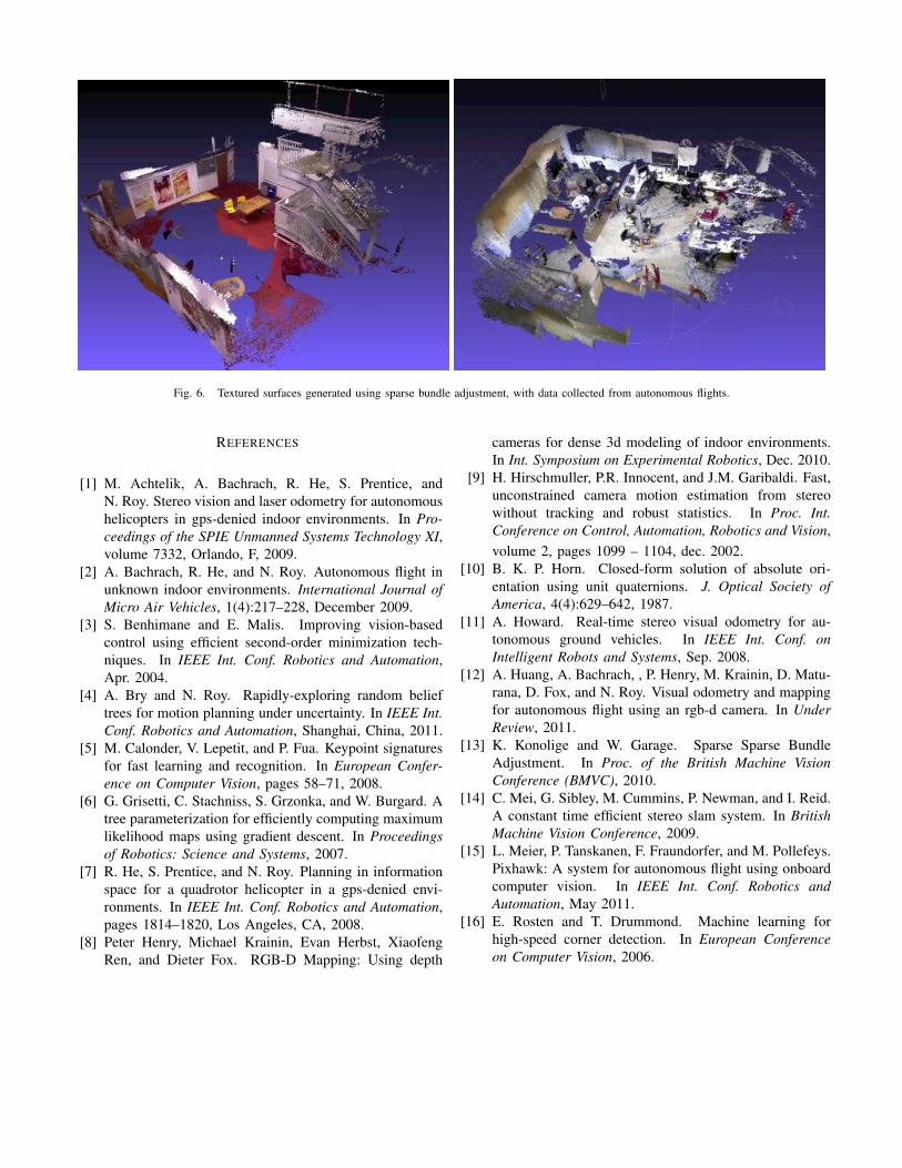
Fig. 6. Textured surfaces generated using sparse bundle adjustment, with data collected from autonomous flights.
REFERENCES
[1] M. Achtelik, A. Bachrach, R. He, S. Prentice, andN. Roy. Stereo vision and laser odometry for autonomoushelicopters in gps-denied indoor environments. In Pro-ceedings of the SPIE Unmanned Systems Technology XI,volume 7332, Orlando, F, 2009.
[2] A. Bachrach, R. He, and N. Roy. Autonomous flight inunknown indoor environments. International Journal ofMicro Air Vehicles, 1(4):217–228, December 2009.
[3] S. Benhimane and E. Malis. Improving vision-basedcontrol using efficient second-order minimization tech-niques. In IEEE Int. Conf. Robotics and Automation,Apr. 2004.
[4] A. Bry and N. Roy. Rapidly-exploring random belieftrees for motion planning under uncertainty. In IEEE Int.Conf. Robotics and Automation, Shanghai, China, 2011.
[5] M. Calonder, V. Lepetit, and P. Fua. Keypoint signaturesfor fast learning and recognition. In European Confer-ence on Computer Vision, pages 58–71, 2008.
[6] G. Grisetti, C. Stachniss, S. Grzonka, and W. Burgard. Atree parameterization for efficiently computing maximumlikelihood maps using gradient descent. In Proceedingsof Robotics: Science and Systems, 2007.
[7] R. He, S. Prentice, and N. Roy. Planning in informationspace for a quadrotor helicopter in a gps-denied envi-ronments. In IEEE Int. Conf. Robotics and Automation,pages 1814–1820, Los Angeles, CA, 2008.
[8] Peter Henry, Michael Krainin, Evan Herbst, XiaofengRen, and Dieter Fox. RGB-D Mapping: Using depth
cameras for dense 3d modeling of indoor environments.In Int. Symposium on Experimental Robotics, Dec. 2010.
[9] H. Hirschmuller, P.R. Innocent, and J.M. Garibaldi. Fast,unconstrained camera motion estimation from stereowithout tracking and robust statistics. In Proc. Int.Conference on Control, Automation, Robotics and Vision,volume 2, pages 1099 – 1104, dec. 2002.
[10] B. K. P. Horn. Closed-form solution of absolute ori-entation using unit quaternions. J. Optical Society ofAmerica, 4(4):629–642, 1987.
[11] A. Howard. Real-time stereo visual odometry for au-tonomous ground vehicles. In IEEE Int. Conf. onIntelligent Robots and Systems, Sep. 2008.
[12] A. Huang, A. Bachrach, , P. Henry, M. Krainin, D. Matu-rana, D. Fox, and N. Roy. Visual odometry and mappingfor autonomous flight using an rgb-d camera. In UnderReview, 2011.
[13] K. Konolige and W. Garage. Sparse Sparse BundleAdjustment. In Proc. of the British Machine VisionConference (BMVC), 2010.
[14] C. Mei, G. Sibley, M. Cummins, P. Newman, and I. Reid.A constant time efficient stereo slam system. In BritishMachine Vision Conference, 2009.
[15] L. Meier, P. Tanskanen, F. Fraundorfer, and M. Pollefeys.Pixhawk: A system for autonomous flight using onboardcomputer vision. In IEEE Int. Conf. Robotics andAutomation, May 2011.
[16] E. Rosten and T. Drummond. Machine learning forhigh-speed corner detection. In European Conferenceon Computer Vision, 2006.