Visual OpenGL: An OpenGL-Based Integrated Development Environment Submitted to Committee Members Kai H. Chang, Ph.D. W. Homer Carlisle, Ph.D. David A. Umphress, Ph.D. by Thomas Benjamin Jones, IV in Partial Fulfillment of the Requirements for the Degree of Master of Computer Science and Engineering May 11, 2002
Transcript
Visual OpenGL: An OpenGL-Based Integrated Development Environment
Submitted to Committee Members
Kai H. Chang, Ph.D. W. Homer Carlisle, Ph.D. David A. Umphress, Ph.D.
by
Thomas Benjamin Jones, IV
in Partial Fulfillment of the
Requirements for the
Degree of Master of Computer Science and Engineering
May 11, 2002
1
Abstract: This project report presents the design and implementation of an integrated development environment developed using and for OpenGL. The environment consists of a suite of utilities that are combined to form an overall system-independent package called Visual OpenGL. This environment addresses a number of problems facing developers of graphics applications by providing graphical interfaces to some of the more inherently visual aspects of OpenGL programming, by providing the means to extend the user interaction capabilities of OpenGL applications, and by automatically generating most of the support code needed to form the basis for OpenGL applications. While Visual OpenGL is targeted mainly at students who are new to graphics programming, it is also suitable for veteran OpenGL programmers who wish to speed up the development of their projects. The report concludes with two detailed examples of how to use the application and suggestions for possible future work in the area.
2
Table of Contents 1 Introduction ............................................................................................................ 3 2 Literature Review ................................................................................................... 4
2.1 OpenGL, the Open Graphics Library..................................................................... 4 2.1.1 Projection....................................................................................................... 4 2.1.2 Modeling........................................................................................................ 5 2.1.3 Rasterization .................................................................................................. 7
2.2 GLUT, the OpenGL Utility Toolkit ....................................................................... 7 2.2.1 Windowing Tasks........................................................................................... 7 2.2.2 User Input ...................................................................................................... 9
3 Project Details ............................................................................................................10 3.1 System Requirements...........................................................................................10
3.2 System Implementation........................................................................................20 3.2.1 GUI Library Implementation .........................................................................21 3.2.2 Color Picker Utility Implementation..............................................................25 3.2.3 GUI Editor Utility Implementation................................................................27 3.2.4 Camera Editor Utility Implementation...........................................................32 3.2.5 Polygon Editor Utility Implementation..........................................................34 3.2.6 Text Editor Utility Implementation................................................................36 3.2.7 Project Wizard Implementation .....................................................................37
4 Example Usage Scenarios ...........................................................................................40 4.1 Example 1: A Basic 2D OpenGL Application ......................................................41 4.2 Example 2: A 3D Application with GUI...............................................................45
5 Conclusions and Future Work.....................................................................................52
3
1 Introduction Graphics applications are inherently visual in nature. Programming languages,
however, are inherently not visual in nature. This fact makes the learning curve for a graphics API (application programming interface) such as OpenGL quite steep. One has to "see" the resulting program in order to know that the underlying code is correct, which leads to more (and more frequent) compilations of the code, which in turn starts to promote a more haphazard programming style ("trial and error" or "build and fix"). A relatively large amount of code is required to produce a relatively small effect; for example, it takes 32 lines of code to draw a simple cube. As a result, syntax errors become more probable.
To complicate matters further, OpenGL has no facilities for handling windowing tasks or user input, so in order to begin learning OpenGL, one must first learn enough of a windowing toolkit such as GLUT (the OpenGL Utility Toolkit) to write the most basic program. Even with GLUT, there is only low-level user interaction capability. There is no library of GUI (graphical user interface) elements such as textboxes, buttons, and other "widgets" that most users tend to take for granted.
The purpose of this project is to implement an integrated development environment
for OpenGL that addresses these issues. The resulting application is targeted mainly at students who are learning OpenGL, but may also be suitable for anyone who wishes to speed up development for an OpenGL application by taking advantage of some of the built-in tools.
More specifically, this project seeks to accomplish the following goals: 1) To provide a set of reusable, purely OpenGL/GLUT-based GUI elements that can
be incorporated into others’ applications and that will be used by this project itself.
2) To provide graphical interfaces to some of the more inherently visual aspects of OpenGL programming, such as color specification, camera placement, and even basic polygon modeling.
3) To provide a "project wizard" that automatically generates a template program based on user-specified parameters, complete with all the code necessary to place and initialize any GUI elements.
4) To provide a basic text editor with built-in macros to help reduce the amount of actual typing needed to add additional code.
4
2 Literature Review This section provides a cursory review of the key concepts from OpenGL and GLUT
that led to the inception of this project. It is not intended to be a lesson in computer graphics concepts or in how to program in OpenGL, but rather to show through discussion of these concepts that this project was in fact justified.
2.1 OpenGL, the Open Graphics Library OpenGL is a software interface to graphics hardware [1]. It is designed as a platform-
independent means of specifying the objects and operations necessary to make three-dimensional graphics applications. Since OpenGL is hardware-independent, user input and windowing tasks are not part of the library and are left up to the specific window system on which the OpenGL application resides.
OpenGL takes the form of a library for ANSI C and contains around 250 commands
as well as several predefined types. Rather than discuss each command in turn, it should suffice to break them down into the three categories relevant to this project: projection, modeling, and rasterization.
2.1.1 Projection In general, projections transform points in a coordinate system of dimension n into
points in a coordinate system of dimension less than n [3]. More specifically for OpenGL, the projection matrix transforms coordinates in 3D space into coordinates on a 2D plane suitable for viewing on a computer screen. The main two methods of performing this transformation are parallel and perspective.
The easiest way to explain the difference in the two without delving into the
underlying linear algebra is to point out that a human being’s vision is essentially a perspective projection; objects farther away from the viewer appear smaller than objects closer to the viewer. Parallel projection, on the other hand, results in objects appearing the same size regardless of their distance from the viewer.
On a slightly more technical level, in perspective projection, the distance from the
center of projection to the plane onto which the projection is taking place is finite, so lines drawn from the center of projection that pass through points of an object and intersect the projection plane (called projectors) are not parallel to each other and converge at the center of projection. In parallel projection, however, the projectors are parallel to each other because the distance from the center of projection to the projection plane is considered to be infinite.
Generally speaking, perspective projection is more appropriate for 3D graphics as the
results look more realistic, like one would see in real life or a photograph, and parallel projection is more appropriate for 2D graphics or for CAD (computer aided design)
5
applications where it is important to get an accurate sense of the dimensions of the objects.
OpenGL has the facilities to handle both perspective projection and orthographic
projection (a special type of parallel projection in which the projectors are perpendicular to the projection plane) using gluPerspective() and glOrtho() respectively. When gluPerspective() is used, it is usually desirable to use it in conjunction with gluLookAt() to produce the best results.
To use gluPerspective(), one needs to specify the field of view angle of the viewing
volume, the aspect ratio of the viewing volume, and the distance range from the “camera” in which an object must lie to be seen (called the near clipping plane and the far clipping plane). Suitable values for these parameters can be rather difficult to establish even for a seasoned OpenGL programmer. Whether or not the objects one draws can even be seen at all depends on first setting these parameters to reasonable values. So, as a result, it may not be clear to a beginner whether a problem with his OpenGL application is resulting from errors in the objects he is drawing or from the parameters he is using for the perspective projection.
A call to gluLookAt() does not affect the projection and is thus more of a modeling
issue, but because it is conceptually so closely related it is discussed here. One can think of the call to gluPerspective() as setting up the “lens” of the camera—it does not actually move the camera to a specific location in space. To do that, one makes a call to gluLookAt() to place the camera and point it toward another location in space. One must keep in mind that because of the nature of perspective projection, placing the camera ten units away from an object that is ten units large does not ensure that the entire object will be visible. So, setting the parameters for gluLookAt() can be as difficult as setting those for gluPerspective(), thus adding another problem a programmer may face while trying to get started with OpenGL.
The best way to learn how to use these function calls effectively is to be able to
experiment with the parameters interactively. It is for this reason that a tool to help set up perspective projection was included in this project.
To use glOrtho(), one must simply establish a correspondence between the corners of
the viewing volume and OpenGL’s coordinate system. There is significantly less “guesswork” in setting up a projection of this type because there are only right angles involved. So, an interactive tool to help set up this sort of projection is not necessary.
2.1.2 Modeling While projection-related commands specify how objects will be transformed in order
to display them on the screen, modeling-related commands specify the actual geometry of these objects as well as the colors present in them. Typically, these commands operate at the vertex level. Multiple vertices are grouped together by OpenGL to form polygons,
6
and the programmer specifies multiple polygons drawn adjacent to each other to build objects.
An individual vertex is usually specified using a command from the glVertex*()
family, such as glVertex3f(), which simply takes the floating point x, y, and z coordinates of the vertex as parameters. At this point it should be noted that OpenGL uses a right-handed coordinate system; for example, when looking at a computer screen, if the positive x-axis points to the right of the screen and the positive y-axis points to the top of the screen, then the positive z-axis points “out of” the screen.
Vertices must be specified between a glBegin() and glEnd() pair of function calls so
that OpenGL can determine what type of primitive to draw (e.g. triangle, rectangle, etc.). Each vertex can be drawn in a different color (which will be discussed shortly) and with a different normal vector (which will also be discussed shortly). Because it can often be difficult to visualize the geometry of vertices and polygons in one’s head, a basic modeling tool was created as part of this project. This tool employs both orthographic projection to help design the actual geometry as well as perspective projection to see how the finished object would look using the parameters taken from the projection tool mentioned above.
A color in OpenGL is normally specified using the respective red, green, and blue
components of that color, which are floating point values that fall in the range of 0.0 to 1.0. For example, black is specified as (0.0, 0.0, 0.0), white is specified as (1.0, 1.0, 1.0), green is specified as (0.0, 1.0, 0.0), etc. However, there is no intuitive relationship between these numbers and the actual color produced. It takes either experience or trial and error to think of a color and translate that color into the proper RBG values. For this reason, a tool to help relate actual colors to their RGB components was created for this project.
A normal vector usually describes a direction that is perpendicular to the surface of a
polygon (there are exceptions, such as if one is trying to create a smooth curved surface such as a sphere, but those exceptions do not apply for purposes of this discussion). Essentially, a normal vector answers the question, “In what direction does this polygon face?” It is necessary to specify normal vectors if one intends to enable lighting calculations in OpenGL, which approximate how a material will reflect light of given properties from a given source, thus making the overall drawing appear much more realistic.
To calculate a normal vector for a polygon, one only needs three vertices. Recall
from geometry that only three points are needed to define a plane. In fact, it is a requirement of OpenGL that all the vertices of a polygon lie on the same plane—the results are unpredictable if they do not—so it is to the programmer’s advantage to use triangles wherever possible (the vertices of a triangle are guaranteed to lie on the same plane). These vertices are used to establish two vectors, and the normalized cross product of these vectors is the direction in which the overall polygon points. Since this process is
7
mathematically intense, a tool to assist in these calculations was included within the modeling tool.
In addition to modeling commands that specify the locations of vertices, there are
commands to transform these vertices by moving them to other locations in space (translation), rotating them around an axis, and changing the apparent size of the objects they form (scaling). While these transformations can sometimes pose problems for the programmer, this project concentrates on assisting with the other aspects of OpenGL already discussed.
2.1.3 Rasterization Rasterization refers to the drawing of actual pixels on the screen, whether they are a
result of the geometry and projection specified earlier or are specified directly. This process is mentioned in this report simply because this project uses the latter method to draw most of the text that appears in the application. There are two things one should keep in mind when rasterizing something directly. First, things that are rasterized directly are not affected by the projection, rotation, or scaling discussed earlier, but are affected by any translation performed. Second, things that are rasterized directly are not specified using vertices, but rather bitmaps. So in this case, a collection of bitmaps representing all the printable ASCII characters was used to rasterize text.
2.2 GLUT, the OpenGL Utility Toolkit The OpenGL Utility Toolkit (GLUT) is a programming interface with ANSI C and
FORTRAN bindings for writing window system independent OpenGL programs [2]. GLUT therefore complements the hardware-independent nature of OpenGL by making windowing tasks and low-level user input independent of the operating system/windowing system on which an OpenGL application resides. Thus, an application written using only OpenGL and GLUT will compile and run the same way on any system for which those libraries exist. For example, this project itself was written entirely in this manner, and thus the exact same code compiles and runs the exact same way on Linux, Solaris, and Windows systems.
2.2.1 Windowing Tasks In order to draw graphics using OpenGL, one must first have somewhere to put the
results. So, a window or full screen console of some sort is needed. Every operating system has a different idea of how such a drawing area should be created, so in order to develop an OpenGL application, one must first learn how to create this drawing area on a given system before one can use any actual OpenGL. This fact can present an especially large problem to a new student of computer graphics because it does not really have much to do with actual graphics programming.
8
So, GLUT provides a more universal way to create a window for drawing or even multiple windows for drawing—this project uses up to twelve such windows at once—and sets up the various display parameters for these windows.
Despite this simplified method for handling windows, a beginner still must learn
enough of GLUT before progressing into actual OpenGL programming, which can still cause some confusion. This project tries to simplify matters even further by automatically generating the necessary code to create and display windows using GLUT.
9
2.2.2 User Input GLUT provides rudimentary facilities for user interaction in the form of callback
functions. The respective functions are called in response to events such as keys being pressed on the keyboard, the mouse moving or one of its buttons being clicked, or events generated by other types of input devices that are not normally used by students of OpenGL (e.g. spaceballs, digitizing tablets).
In the case of a keyboard-related event, the identity of the key that was pressed and
the coordinates of the mouse at the time the key was pressed are sent to the user-defined callback function to handle as the programmer sees fit. For events relating to the movement of the mouse, the coordinates of the mouse are sent to the respective callback. For events relating to mouse buttons being clicked, the identity of the button, the state of the button (whether it was pushed down or released), and the coordinates of the mouse are sent to the respective callback. In addition, GLUT offers a small cascading popup menu system that can be attached to one of the mouse buttons and handled by a similar callback function.
While these facilities do vastly increase the amount of user-interaction possible in
OpenGL/GLUT programs, they are still rather low-level. For example, there is no way other than using standard I/O functions in C to ask the user to enter a number or a name. There is no way other than online documentation of some sort for a user to know the effects of pressing certain keys or clicking with the mouse in certain areas. There are no standard user interface elements one can create in an application (e.g. textboxes, checkboxes, buttons).
It was clear from the beginning that this project would need some of those standard
GUI widgets. In keeping with the spirit of OpenGL and GLUT being platform-independent, part of this project was to construct a set of reusable GUI elements built entirely with OpenGL and GLUT, and a visual layout tool to help one incorporate these elements into an OpenGL application. These widgets can be used to retrieve data from the user, set parameters within the application, remove the need to memorize a long list of “hotkeys,” and make the application look a bit more professional overall.
10
3 Project Details
3.1 System Requirements Visual OpenGL is an integrated development environment specifically geared toward
OpenGL. Since OpenGL is designed to be hardware-independent and GLUT is designed to be window system-independent, one of the governing requirements is that the overall Visual OpenGL package must also be system-independent. This first requirement automatically dictates the next, which is that it must provide its own user interface elements; in other words, it cannot rely on system-specific libraries such as Motif or MFC. The Visual OpenGL project can be broken down into the following pieces, the requirements of which will be discussed in greater detail in the coming sections: GUI library, Color Picker utility, GUI Editor utility, Camera Editor utility, Polygon Editor utility, Text Editor utility, and a Project Wizard that combines all of the other utilities in a logical manner to create the overall environment.
11
3.1.1 GUI Library Requirements A graphical user interface widget is inherently object-oriented in nature. It has an
appearance, a location on the screen, data of some sort that it maintains, and actions that it performs when the user interacts with it by clicking on it with the mouse, pressing a key on the keyboard while it is selected, etc. It therefore makes sense that the GUI library itself should be object-oriented in its design. In fact, since all user interface widgets have so much in common, it makes sense to derive them all from an abstract “GLWidget” base class. In this manner, it becomes easier for polymorphism to be incorporated into the design, meaning a user of the library is able to invoke methods on a user interface widget object without worrying about its type.
A widget should provide methods to allow a calling program to set and retrieve
various state information pertaining to it, such as position, size, color, and content. Such state retrieval methods allow for the creation of the GUI Editor utility, which will be discussed later.
Not every conceivable type of widget is needed for the Visual OpenGL application,
so the GUI library should be easily expandable to allow new types to be added in the future. The following is a table summarizing the types of widgets developed for this project and their respective capabilities:
12
Widget Type Description Keyboard Actions Mouse
Actions Label A string of text. (None) (None)
Textbox A box with an optional label
containing a single line of text, which the user can edit.
Adds, deletes text. Positions cursor.
Copies, cuts, pastes text.
Positions cursor. Selects
text.
TextArea
Essentially a textbox that can hold multiple lines of text; has horizontal and vertical scrollbars that appear as
needed. Can read its content from and write it to files.
Same as Textbox. Plus, automatically scrolls text when
applicable.
Same as Textbox. Plus,
scrolls text when
applicable.
Floatbox A textbox that can only hold floating-point numbers. Same as Textbox. Same as
Textbox. Clamped Floatbox
A floatbox limited to a range of possible values. Same as Textbox. Same as
Textbox.
Intbox A textbox that can only hold integer values. Same as Textbox. Same as
Textbox.
Button A labeled rectangular object
that performs a function when clicked.
(None) Executes function.
Checkbox A small, labeled box
representing two possible states: checked, unchecked.
(None) Toggles state.
RadioGroup A group of checkboxes,
exactly one of which can be “checked” at a time.
(None) “Checks” respective member.
Slider
A vertical strip with a “handle” that can be moved
between its top and bottom to represent a value in a given
range.
(None) Moves “handle.”
Table 3.1.1-1: Widget Requirements
13
3.1.2 Color Picker Utility Requirements The purpose of the Color Picker is to provide a graphical interface to the process of
specifying a color in OpenGL. Recall that a color in OpenGL is specified using three floating-point numbers between 0.0 and 1.0, one for each component. Therefore, the main requirement of this utility is that there should be an object drawn using a particular color, and the corresponding numeric components of that color should be displayed.
Next, the user should be able to change the particular color used to draw the object.
To maintain the correspondence between the actual color and its numeric components, the user should be able to specify the color numerically or visually. In order to specify the color visually, a user should be able to see the color he wishes to use and click on it with the mouse. In order for the user to see the desired color, all possible colors, or a reasonable subset, should be displayed at once. There should be an online reference of some sort that explains how to use the utility.
Finally, since there is no system-independent version of a “clipboard,” the user should
be able to print the OpenGL representation of the color to the standard output device to facilitate use of this utility in conjunction with other applications.
From these requirements, something about the design is already apparent. Since a
color is made up of three components, but a computer screen is only two-dimensional, it is not very practical to try to display all possible colors at once. Therefore, the colors can be displayed in two sections: One section that shows all possible colors resulting from altering the current red and green components while leaving the blue component unchanged, and another section that shows all possible colors resulting from altering the current blue component while leaving the red and green components unchanged.
14
3.1.3 GUI Editor Utility Requirements Since this project makes extensive use of GUI elements, it makes sense to develop a
tool that allows one to design a user interface interactively and visually. That way, as the project progresses, the tool can be used to “bootstrap” other parts of the project as well as parts of itself. As with the Color Picker, there should be an extensive online reference for using the tool.
The GUI Editor should allow the user to do four main things: 1) Create an arbitrary number of user interface widgets of any given type from the
GUI library and delete any widgets already created. 2) Edit the properties of any widgets created. The applicable properties will change
depending on the type of widget to be edited. Since some of these properties are related to color, a facility to use the Color Picker utility where appropriate should be included.
3) Arrange the locations of the any widgets created within a window to establish the look and feel of the resulting interface.
4) Initialize the widgets to default values that will be used when the resulting program is started.
15
3.1.4 Camera Editor Utility Requirements The purpose of the Camera Editor is to provide a graphical interface to the process of
specifying a “camera” in OpenGL. This process involves two separate but related parts: a projection transformation using gluPerspective(), and a modeling transformation using gluLookAt(). The user should have access to the main parameters of each of these functions, and the results of changing these parameters should appear visually. More specifically, for gluPerspective(), the user should be able to change the field of view angle, the near clipping plane, and the far clipping plane. For gluLookAt(), the user should be able to change the (x, y, z) position of the camera and the (x, y, z) target of the camera.
In order to see how different parameters produce different results, it is necessary to
draw a reference object of a known size and position. In addition, to help a user set up the camera for a particular scene, it should be possible to change the position and size of this reference object. Ideally, the user would be able to import any geometry from his application into this utility to use as a reference, but such a facility would go well beyond the scope of this project, as it would essentially require a small OpenGL interpreter.
Finally, as with the Color Picker, an extensive online reference should be provided as
well as a way to print the OpenGL representation of the resulting parameters to the standard output device.
16
3.1.5 Polygon Editor Utility Requirements The purpose of the Polygon Editor is twofold: To provide a graphical interface to the
process of specifying basic geometric primitives in OpenGL, and to assist with calculating normal vectors for these primitives to be used in conjunction with lighting. The Polygon Editor is not intended to be a full-featured modeling program such as Lightwave or 3DS Max. Such a tool would be well beyond the scope of this project.
It is generally a bad idea to use polygons that are made up of more than 4 vertices;
each such polygon must be surrounded by calls to glBegin(GL_POLYGON) and glEnd(), adding more overhead to the drawing code, and the more vertices there are, the greater the chance that not all of them lie on the same plane. A polygon made up of less than three vertices will not have a normal vector, and will therefore not respond to lighting. Such polygons are not very useful in most OpenGL applications, so the Polygon Editor should deal just with three-sided and four-sided polygons.
The Polygon Editor should allow the user to choose between GL_TRIANGLES and
GL_QUADS, and it should allow the user to enter the appropriate number of vertices for each. It is necessary to define the vertices of a polygon in counterclockwise order with respect to the direction the polygon is facing, so the portion of the Polygon Editor’s interface that allows the user to enter vertices should be arranged with that fact in mind. Additionally, since each vertex can be drawn using a different color, the ability to use the Color Picker to select a color for each vertex should be included.
The normal vector for each polygon should be calculated and reported to the user.
However, the user should not be able to edit the normal vector since it is calculated based on the polygon’s vertices. In the case of a four-sided polygon, only the first three vertices are needed to calculate the normal vector. A four-sided polygon is somewhat of a special case since there is a chance that not all four vertices lie on the same plane, and as it turns out, the normal vector is a good way to check for this problem: If the normal vector calculated using the first three vertices of the polygon does not agree with the normal vector calculated using the last three vertices of the polygon, then the polygon is non-planar and the user should be warned of that fact.
There should be a way for the user to add more polygons and delete existing ones, but
this facility need not be too sophisticated else this one utility will be more complex than the project as a whole.
There should be several visual representations of the polygons. Since it is important
to get an accurate sense of the dimensions of the polygons, three orthographic views of the polygons—front, top, and left—should be provided. The user should be able to set the coordinate system used for these views to suit the needs of a particular application. In addition, a perspective view of the polygons with optional lighting that allows the user to see the geometry from all possible angles should be provided. The perspective view should use the parameters set by the Camera Editor utility. The normal vector of each
17
polygon should be represented, most likely with a line originating from center of the polygon and pointing in the proper direction.
Finally, as with the Color Picker and Camera Editor, there should be an online
reference and a way to print the resulting geometry to the standard output device. Ideally, the geometry should be output in an optimized way, with any and all triangles listed first, followed by any and all rectangles. Since the color and the normal vector are states in OpenGL, the code to set these states may not always be needed (e.g. if the current color is already black, there is no need to set it to black). As such, the code that is output should also be optimized with respect to color and normal vector changes.
18
3.1.6 Text Editor Utility Requirements The purpose of the Text Editor is to allow the user to view and manipulate any
program code generated by Visual OpenGL. Since any such program code will be ASCII text, and since a user may wish to write or edit code not generated by Visual OpenGL, the Text Editor should be able to load and save files using user-specified names.
The actual text editing capabilities of this utility may be fairly basic. Essentially, the
utility may rely on a Text Area widget from the GUI library for most of its functionality. In addition, templates for commonly used OpenGL code segments that can be easily inserted into the text should be included. Finally, data from the Color Picker and the Polygon Editor should be available as code that can be easily inserted into the text.
19
3.1.7 Project Wizard Requirements The Project Wizard is essentially the heart of the whole project since it ties all of the
other utilities together to form a coherent environment for developing OpenGL applications. Its overall purpose is to generate an OpenGL program according to parameters set by the user, including the necessary code to place and initialize any user interface elements created using the GUI Editor.
The Project Wizard should allow the user to designate a filename to use for the
generated code as well as the title of the corresponding window that code will produce. Also, the user should be able to specify the background color of the generated window (using the Color Picker if desired), the shading model to use in the window, and whether or not lighting will be used.
The user should be able to choose from among several different types of applications
to develop, which mainly differ with respect to projection options. For example, perhaps the user wishes to create a simple 2D application, or perhaps the user wishes to develop a more advanced 3D application containing GUI elements. For 2D applications, the user should be able to specify the coordinate system to use (i.e. the parameters that will be used by glOrtho() within the application). For 3D applications, the user should have access to the Camera Editor to set up the perspective projection. For applications containing user interface elements, the user should have access to the GUI Editor. Finally, for applications containing multiple coordinate systems (e.g. a 3D application that also has a GUI), the user should be able to place the secondary coordinate system within the overall window.
When all the parameters are set as desired, the Project Wizard should then generate
the necessary program code, write this code to the specified file, and open the finished file in the Text Editor so that the user can inspect it and edit it as required.
20
3.2 System Implementation The entirety of the Visual OpenGL package was written using only OpenGL and
GLUT for all drawing and windowing functions. The underlying language used was C++ along with the Standard Template Library (STL). These facts guarantee that Visual OpenGL will run on any system for which OpenGL and GLUT exist, and that it will compile on any system that also has a C++ compiler with the STL. The top-level window of the application looks like Figure 3.2-1 below.
Figure 3.2-1: Main Visual OpenGL Window
This main window provides access to some online reference information as well as access to each of the application’s utilities. The code behind this window as well as most of the code behind all the other windows in the project was in fact generated using the project itself. The following sections will describe the implementation of each of the project’s pieces in more detail.
21
3.2.1 GUI Library Implementation The user interface elements described in Table 3.1.1-1 were implemented using C++
in conjunction with OpenGL and GLUT. These widgets were all derived from an abstract GLWidget class to collect common functionality and to allow a programmer using the library to take advantage of polymorphism. An intermediate class derived from GLWidget called TextWidget was created to collect the common functionality of all widgets that contain text data, and all such widgets were derived from TextWidget rather than GLWidget. Figure 3.2.1-1 shows the final appearances of all the widgets.
Figure 3.2.1-1: GUI Elements
Rather than describing every detail relating to how these widgets were programmed, this report will focus only on the relevant methods used by the rest of the Visual OpenGL package.
Every class of widget inherits the following methods from the base class related to
GLUT, whether it chooses to override those methods or not: • itsKeyboardFunc(unsigned char key, int x, int y):
Called when: an ASCII key being pressed on the keyboard. Parameters passed: the identity of the key and the mouse coordinates at the time the key was pressed. Applies to: members of class TextWidget. o CTL-C copies any selected text to Visual OpenGL’s clipboard, CTL-X cuts
(deletes and copies to the clipboard) any selected text, and CTL-V pastes the contents of Visual OpenGL’s clipboard.
o For all keys except CTL-C, any selected text is first deleted. The backspace and delete keys delete the character to the left and the right of the cursor, respectively, assuming that it exists. All other keys insert the corresponding character into the text, assuming it is allowed by the particular widget type (e.g. only numbers, a negative sign, and a decimal point are allowed in a Floatbox).
• itsSpecialFunc(int key, int x, int y): Called when: a non-ASCII key (e.g. arrow key) is pressed. Parameters passed: the identity of the key and the mouse coordinates at the time the key was pressed. Applies to: members of class TextWidget.
22
o The arrow keys move the cursor one unit in the respective direction. HOME and END move the cursor to the beginning of the line and the end of the line, respectively.
o In the case of a TextArea, PAGE UP and PAGE DOWN move the cursor up and down about a page, respectively.
• itsMouseFunc(int button, int state, int x, int y): Called when: a mouse button is pressed or released. Parameters passed: the identity of the button, whether the button was pressed or released, and the mouse coordinates at the time the button was pressed or released. Applies to: all widgets. o For members of TextWidget, the text insertion cursor is positioned at the
nearest character to the mouse. For a TextArea, if the mouse is clicked on one of the scrollbars, nothing happens; if the mouse is clicked in the area between one of the scrollbars and an edge of the TextArea, the text scrolls by approximately 10% in the respective direction.
o For a Button, if the mouse is clicked and subsequently released on the Button, the Button will perform its assigned function.
o For a Checkbox, if the mouse is clicked and subsequently released on the Checkbox, the state of the Checkbox will toggle.
o For a RadioGroup, the option nearest the mouse will be selected if the mouse is clicked and subsequently released on that option.
o For a Slider, if the mouse is clicked on the handle, nothing will happen. If the mouse is clicked between the handle and the top or bottom of the Slider, the value will be incremented very slightly or decremented very slightly, respectively.
• itsMotionFunc(int x, int y): Called when: the mouse is moved while a button is held down. Parameters passed: the mouse coordinates. Applies to: members of class TextWidget and members of class Slider. o For members of class TextWidget, any text between the cursor’s original
position and the mouse’s current position is selected. For a TextArea, if the mouse was previously clicked on a scrollbar, the scrollbar will move along with the mouse cursor and the text will scroll in proportion to the scrollbar’s new location. If the mouse was clicked on the lower-right corner of the TextArea and the TextArea has permission to be resized, the lower-right corner of the TextArea will move to the mouse’s new location, thus resizing the TextArea. If the mouse was clicked on the TextArea’s label and the TextArea has permission to be moved, the entire TextArea will move to the mouse’s new location.
o For a Slider, if the mouse was previously clicked on the handle, the handle will move along with the mouse cursor and the Slider’s value will be set in proportion to the handle’s new location.
• itsIdleFunc(): Called when: there are no other pending events or commands.
23
Parameters passed: none. Applies to: members of class TextWidget. o This function is responsible for making the cursor blink.
• draw(): Called when: the window needs to be redrawn. Parameters passed: none. Applies to: all widgets. This method is what actually uses OpenGL code to give a widget its appearance and display it on the screen.
The above methods were designed to correspond to the callback functions present in a typical GLUT program. The programmer must register his own callback functions of the same form with GLUT, and within those callback functions, call the respective methods for any widgets present in the program. Note that the Project Wizard automatically sets up and registers all the necessary callback functions, so only a user of the GUI library who is not using the Project Wizard needs to worry about these methods.
In addition to the methods related to GLUT, the GUI library provides methods to set
and retrieve state information about a widget. Similar to the way OpenGL has “families” of closely related functions (e.g. glVertex2f(), glVertex3f(), glVertex2d(), etc.), these accessor methods can be grouped into two families: glwidgetSet*() and glwidgetGet*(). These methods all require a property name (from an enumerated PROPERTY type) and zero or more other parameters. The following is a description of each method from these families:
• void glwidgetSetPropertyi(PROPERTY propertyname, int value), int glwidgetGetProperyi(PROPERTY propertyname): Called when: the widget property to be set or retrieved is an integer. Parameters: the name of the property, and the integer value to which the property should be set.
• void glwidgetSetPropertyf(PROPERTY propertyname, float value), float glwidgetGetPropertyf(PROPERTY propertyname): Called when: the widget property to be set or retrieved is a floating-point value. Parameters: the name of the property, and the floating-point value to which the property should be set.
• void glwidgetSetProperty2f(PROPERTY propertyname, float value1, float value2), void glwidgetGetProperty2f(PROPERTY propertyname, float &value1, float &value2): Called when: the widget property to be set or retrieved is made up of two floating-point values. Parameters: the name of the property, and the floating point values either to which the property should be set, or into which the retrieved property should be placed.
• void glwidgetSetProperty3f(PROPERTY propertyname, float value1, float value2, float value3), void glwidgetGetProperty3f (PROPERTY propertyname, float &value1, float &value2, float &value3): Called when: the widget property to be set or retrieved is made up of three floating-point values.
24
Parameters: the name of the property, and the floating point values either to which the property should be set, or into which the retrieved property should be placed.
• void glwidgetSetPropertys(PROPERTY propertyname, const char *value), string glwidgetSetPropertys(PROPERTY propertyname): Called when: the widget property to be set or retrieved is a string. Parameters: the property name, and the string value to which the property should be set.
• void glwidgetSetPropertyis(PROPERTY propertyname, int offset, const char *value), string glwidgetGetPropertyis(PROPERTY propertyname, int offset): Called when: the widget property to be set or retrieved is a string, and the widget contains multiple instances of this type of property. Parameters: the property name, the particular instance of this property that should be set or retrieved, and the string value to which this property should be set.
If any of these methods is used to attempt to set a non-existent property of any widget, an error is returned and an error message is printed to the standard error device; perhaps in a future revision it may be more appropriate to throw a runtime exception in such instances.
The available widget properties for all widgets (and the suffixes of the corresponding
glwidget*() family members with which they are associated) that a user of the GUI library is most likely to need are:
• Position: POS (2f), POS_X (f), POS_Y (f) • Dimensions: WIDTH (f), HEIGHT (f) • Text in a TextWidget: TEXT (s) • State of a Checkbox: CHECKBOX_STATE (i) • Selected Button in a Radio Group: SELECTED_RADIOBUTTON (i) • Current Value of a Slider: SLIDER_VALUE (f)
Most of the other available properties pertain to the colors of certain parts of a widget,
both under normal circumstances and when that widget is selected. As such, these properties are omitted from this discussion.
25
3.2.2 Color Picker Utility Implementation The Color Picker was implemented using several elements from the GUI library as
well as additional OpenGL drawing code. Figure 3.2.2-1 shows the finished utility.
Figure 3.2.2-1: The Color Picker
The utility consists of seven main areas: • The red-green area (the largest rectangle). This rectangle was made using a single
polygon with different colors for each vertex; the color of the lower-left corner is (0, 0, current blue component) and the color of the upper-right corner is (1, 1, current blue component). This area shows all possible colors given the current blue component. Clicking or dragging the mouse in this area will set the current red and green components based on the mouse’s location and will leave the crosshair at this new location. The color of the crosshair will be white or black depending on the overall intensity of the color nearest it.
• The blue area (the tall, narrow rectangle). This rectangle was made using a single polygon with different colors for each vertex. The color of the bottom vertices is (current red component, current green component, 0) and the color of the top vertices is (current red component, current green component, 1). This area shows all possible colors given the current red and green components. Clicking or dragging the mouse in this area will set the current blue component based on the mouse’s location and will leave the small arrow indicator at this new location.
• The RBG boxes. These boxes were made using ClampedFloatboxes from the GUI library, limited to values between 0.0 and 1.0. These boxes display the numeric components of the currently selected color. Changing the values in these boxes changes the selection indicators in the red-green and blue areas appropriately.
• The current color (the smallest rectangle). This rectangle was made using a polygon drawn in the currently selected color, as read from the RGB boxes. In
26
other words, this is without any doubt the color that would appear should one use the reported numeric values in an OpenGL program.
• stdout: Clicking this button causes the utility to print an appropriate glColor3f() function call to the standard output device (stdout) based on the currently selected color.
• Help: Clicking this button brings up a window containing reference information for the Color Picker.
• Close: Clicking this button closes the Color Picker. Important: On Microsoft Windows™ systems, clicking the “X” in the top-right corner will exit the entire Visual OpenGL application, not just the Color Picker.
27
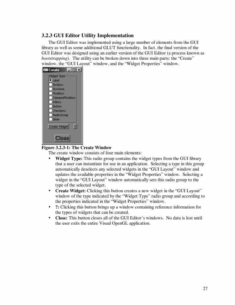
3.2.3 GUI Editor Utility Implementation The GUI Editor was implemented using a large number of elements from the GUI
library as well as some additional GLUT functionality. In fact, the final version of the GUI Editor was designed using an earlier version of the GUI Editor (a process known as bootstrapping). The utility can be broken down into three main parts: the “Create” window, the “GUI Layout” window, and the “Widget Properties” window.
Figure 3.2.3-1: The Create Window
The create window consists of four main elements: • Widget Type: This radio group contains the widget types from the GUI library
that a user can instantiate for use in an application. Selecting a type in this group automatically deselects any selected widgets in the “GUI Layout” window and updates the available properties in the “Widget Properties” window. Selecting a widget in the “GUI Layout” window automatically sets this radio group to the type of the selected widget.
• Create Widget: Clicking this button creates a new widget in the “GUI Layout” window of the type indicated by the “Widget Type” radio group and according to the properties indicated in the “Widget Properties” window.
• ?: Clicking this button brings up a window containing reference information for the types of widgets that can be created.
• Close: This button closes all of the GUI Editor’s windows. No data is lost until the user exits the entire Visual OpenGL application.
28
Figure 3.2.3-2: The GUI Layout Window Figure 3.2.3-2 shows an example of what the “GUI Layout” window might contain.
Mainly, it contains all of the widgets created using the “Create” window. Clicking on a widget with the mouse will select the widget. Clicking and dragging a widget will change the widget’s location in the window and update the “Widget Properties” window to reflect the new location. The white rectangle in the figure represents the section of the window that will use a different coordinate system than the GUI elements. This rectangle is drawn using the background color set in the Project Wizard (discussed later), and will only appear when Visual OpenGL is being used to create a more advanced type of project.
The appearance of the “Widget Properties” window depends on the type of widget
indicated in the “Widget Type” radio group in the “Create” window. Figure 3.2.3-3 shows enough screenshots of the “Widget Properties” window to depict all the possible controls.
a) b)
29
c) d) Figure 3.2.3-3: The Widget Properties Window a) for a TextArea, b) for a
ClampedFloatbox, c) for a Button, and d) for a RadioGroup.
30
The available widget property controls in this window are: • Name: This box contains a name that will be associated with a given widget in
the generated program. All the widgets will be placed into a single vector of type GLWidget* to take advantage of polymorphism, so these names will appear as preprocessor definitions that associate the name with the index of the widget in the vector.
• Label: This box contains the text of the label that will appear on the widget. • Edit Mode: When this radio group is set to the “Place” option, clicking and
dragging a widget with the mouse in the “GUI Layout” window will change the location of the widget. When this radio group is set to the “Initialize” option, the widgets in the “GUI Layout” window behave just as they will in the final program, and the initial values that they should have on program startup can be set.
• X, Y: These boxes contain the (x, y) coordinates of the widget. • Colors: This button brings up a window that allows the user to specify all the
available colors for a given widget: normal color, color when selected, normal label color, label color when selected, normal text color, and text color when selected. These colors can optionally be set using the Color Picker.
• Help: This button brings up a window containing online reference information pertaining to the available widget properties.
• Apply: This button appears only when a widget is selected in the “GUI Layout” window. Clicking it will assign all the properties specified in the “Widget Properties” window to the selected widget.
• Delete: This button appears only when a widget is selected in the “GUI Layout” window. Clicking it will delete the currently selected widget.
• Length: For widgets of class Textbox, Floatbox, ClampedFloatbox, and Intbox, this box sets the number of characters that the widget will hold.
• Write Permission: For members of class TextWidget, this box specifies whether the user will be able to alter the text contained in the widget.
• MinValue, MaxValue: The number in a ClampedFloatbox must fall within this range. These two parameters also specify the range of a Slider.
• Width: This parameter sets the minimum width of a TextArea or Button. For a Button, setting this width to a value smaller than the label’s width will force the Button to use the minimum width required in order for the label to fit.
• Height: This parameter sets the minimum height of a TextArea or Slider. • Font: This radio group sets the font for a TextArea or Button. There are seven
fonts available for a TextArea and two available for a Button. • Resize Permission: This box determines whether the user will be able to resize a
TextArea. • Move Permission: This box determines whether the user will be able to move a
TextArea. • Entry: This parameter sets the text of an option in a radio group. • Add Entry: This button adds an option with the text specified by “Entry” to the
selected radio group.
31
• Delete Entry: If an option in the radio group has been selected, this button will delete that option from the group. If no option has been selected, the last option in the group will be deleted.
32
3.2.4 Camera Editor Utility Implementation The Camera Editor was implemented using the GUI Editor Utility and an additional
perspective projection coordinate system. The additional coordinate system contains a reference object to give the user feedback about how the parameters affect the viewing volume.
Figure 3.2.4-1: The Camera Editor
33
The Camera Editor controls are divided into the following sections: • Projection: These controls deal with the parameters for gluPerspective(), which
sets up a perspective projection viewing volume. o FOV: This slider sets the field of view angle. This parameter can be set to
any value between 0.0 and 180.0 normally, but the Camera Editor restricts this parameter to values that generally produce more reasonable result: 45.0 minimum and 70.0 maximum.
o NearClip: This value represents the near clipping plane of the viewing volume. In other words, anything closer to the camera than this distance will not be seen.
o FarClip: This value represents the far clipping plane of the viewing volume. In other words, anything farther away from the camera than this distance will not be seen.
• Camera Position/Target: These controls deal with the parameters for gluLookAt(), which applies a series of modeling transformations to place the camera in space. o Camera Position: These boxes set the (x, y, z) position of the camera in
space. o Camera Target: These boxes set the (x, y, z) position toward which the
camera is pointed. • Reference Object: These controls deal with the reference object (the spinning 3D
cube). o Object Position: These boxes set the position of the reference object in space. o Object Size: These boxes set the size of the reference object along each of the
three axes. • stdout: Clicking this button prints the gluPerspective() and gluLookAt() function
calls needed to specify the current camera setup in OpenGL to the standard output device.
• Help: Clicking this button brings up a window containing reference information for the Camera Editor.
• Close: This button closes the Camera Editor.
34
3.2.5 Polygon Editor Utility Implementation The Polygon Editor was implemented using the GUI Editor and four additional
coordinate systems to represent the geometry. Three of these coordinate systems are orthographic: Front (XY plane), Top (XZ plane), and Left (ZY plane). The other coordinate system uses perspective projection based on the parameters in the Camera Editor and the geometry within this system is constantly rotating to display it from all possible angles.
Figure 3.2.5-1: The Polygon Editor
35
The Polygon Editor controls are divided into the following sections: • View: These controls set up the orthographic coordinate systems (the Front, Top,
and Left views). The user can adjust these to get a better view of the geometry in the scene.
• Polygon Type: This radio group determines whether the current polygon is a triangle (GL_TRIANGLES) or a rectangle (GL_QUADS).
• Vertices: These boxes specify the (x, y, z) coordinates of the vertices of the current polygon. Three vertices are shown when the current polygon is a triangle, and four are shown when the current polygon is a rectangle. The vertices are arranged in counterclockwise order so that the user can get a sense of how the vertices should be arranged in space.
• Normal Vector: These boxes contain the components of the calculated normal vector for the current polygon. Since these are calculated, the user cannot change these. Recall that the normal vector is used in conjunction with lighting and essentially answers, “In which direction does this polygon point?”
• Enable Lighting: If this box is checked, a default light will be turned on in the Perspective view.
• Add: Clicking this button commits the current polygon to memory and adds another one to the object that has the same parameters. This new polygon then becomes the current polygon, and all subsequent operations will affect it, but not the polygon previously committed to memory.
• Colors: Clicking this button brings up a window that allows the user to specify the color of each vertex, optionally by using the Color Picker.
• Delete: Clicking this button deletes the current polygon (if there are more than one defined) and sets all controls to match the parameters of the polygon previously created.
• stdout: Clicking this button prints to the standard output device the OpenGL code necessary to draw the current geometry. The code is optimized such that any and all triangles are drawn first, followed by any and all rectangles. Code to change the color and normal vector is printed only as needed to avoid redundancy.
• Help: Clicking this button brings up a window containing reference information for the Polygon Editor.
• Close: Clicking this button closes the Polygon Editor.
36
3.2.6 Text Editor Utility Implementation The Text Editor was implemented by manually creating a TextArea widget and a few
other user interface elements. Also, a menu was attached to the right mouse button to allow the user to insert several types of OpenGL code templates as well as change the font used to draw the text.
Figure 3.2.6-1: The Text Editor Window
The controls of the Text Editor are: • Close: Clicking this button closes the Text Editor. The text is not lost until the
user exits the entire Visual OpenGL application. • File: This box contains the name of the text file. • Load: Clicking this button loads the file specified in the “File” box and displays it
in the text area. The label of the text area is changed to reflect the file name. • Save: Clicking this button saves the text in the text area to the file specified in the
“File” box.
37
3.2.7 Project Wizard Implementation The project wizard was implemented using the GUI Editor. It gives the user access to
all parameters needed to generate the code for an OpenGL/GLUT application.
Figure 3.2.7-1: The Project Wizard Window
38
The Project Wizard contains the following controls: • Window Title: The text in this box will be used as the title of the window that the
generated program will create. For example, the title of the Project Wizard window is “Project Wizard.”
• Main Background: These boxes set the main background color of the window that the generated program will create. Clicking the “Get” button next to these boxes automatically fills in the values based on the color selected in the Color Picker.
• Shading: This radio group sets the shading model that the generated program will use. This is either GL_FLAT, meaning that a polygon will be filled with a single color, or GL_SMOOTH, meaning that the color of a polygon will vary across its surface depending on the colors of its vertices.
• Enable Lighting?: If this box is checked, the generated program will set up and turn on a default light.
• Help: Clicking this button brings up a window containing reference information about the Project Wizard.
• Close: Clicking this button closes the Project Wizard. None of the current settings are lost until the user exists the entire Visual OpenGL application.
• Projection: This radio group specifies the overall type of application to be generated. o 2D: A program that uses a simple orthographic projection coordinate system
will be generated. o 3D: A program that uses a simple perspective projection coordinate system
will be generated, the parameters for which are taken from the Camera Editor. o GUI Only: A program that uses a coordinate system appropriate for user
interface elements will be generated. In other words, the OpenGL coordinates will be set up to be the same as the window/mouse coordinates.
o 2D w/ GUI: A program that uses two coordinate systems will be generated. One coordinate system will be appropriate for user interface elements. The other coordinate system will be restricted to part of the window and will use a simple orthographic projection coordinate system.
o 3D w/ GUI: A program that uses two coordinate systems will be generated. One coordinate system will be appropriate for user interface elements. The other coordinate system will be restricted to part of the window and will use a simple perspective projection coordinate system.
• GUI Background: These boxes set the background color of the GUI portion of the window that the generated program will create. Clicking the “Get” button next to these boxes automatically fills in the values based on the color selected in the Color Picker.
• Coordinate System: For 2D applications, this section allows the user to set the relevant parameters for the orthographic projection. For 3D applications, this section contains a button that, when clicked, brings up the Camera Editor to allow the user to set the relevant parameters for the perspective projection.
• Placement: For 2D w/GUI and 3D w/GUI applications, this section allows the user to set the location and size of the 2D or 3D portion of the window.
39
o OffsetX, OffsetY: These boxes specify the offset in window coordinates of the 2D or 3D portion of the window.
o BorderX, BorderY: These boxes specify how much space should be left between the 2D or 3D portion of the window and the edge of the window. In other words, resizing the window also resizes the 2D or 3D portion of the window.
• File: This box contains the name of the file that will be generated. This name will also be used as a base for the names of the functions within the generated program.
• Include Main?: If this box is checked, the generated program will include the necessary libraries and will contain a main function that will initialize and display the window generated by Visual OpenGL. A user developing an application that contains multiple windows would not want this box to be checked for each window.
• Generate Code: This button generates the code needed to produce an OpenGL application that conforms to all of the specified parameters. This includes the code necessary to place and initialize any GUI elements as well as the code to allow the user to interact with these elements. The generated program contains sufficient comments so that a user of Visual OpenGL can understand how it works.
40
4 Example Usage Scenarios This section presents two detailed examples of how to use the Visual OpenGL
application. This section can be thought of as a “Getting Started” manual addressed to the end user of Visual OpenGL. The first example provides sufficient information for a user to get started with the application and use it to create a basic template for an OpenGL program. The second example demonstrates some of the more advanced features of the application, such as designing a user interface and using the polygon modeler. The following style conventions are used:
• Actions that the user should perform are written in italics. • Text and numbers that the user should type are enclosed in “quotation marks”—
the user should not actually type the quotation marks. • The names of windows and labels of user interface elements are written in bold. • Explanations of actions and the concepts related to them are written in regular
type. • Program code and file names are represented in a monospace font.
41
4.1 Example 1: A Basic 2D OpenGL Application This example will introduce you to the basic features of Visual OpenGL and show
you how to use it to create a simple 2D OpenGL application that draws a single smooth-shaded triangle. The resulting application will look like this:
Figure 4.1-1: Completed Example 1
• Start the Visual OpenGL program. The main window of the program should look like Figure 3.2-1.
• Click the Project Wizard button. The Project Wizard window will appear. • Change the Window Title to “Visual OpenGL Example 1”—this text will appear
as the name of our final application window. • Click the GL_SMOOTH option in the Shading radio group. This indicates that
we will be using smooth shading in the application we are creating. Recall that with smooth shading, the color of a polygon will vary across its surface based on values interpolated among the colors of its vertices.
• Change the File to “example1”—the resulting file will be named example1.cpp and all the function names will begin with example1 as a prefix.
• Click the Get button next to the Main Background color boxes. The Color Picker window, shown in Figure 3.2.2-1, will appear. This tool reports the RGB components of the currently selected color. The largest rectangle represents the possible values for the red and green components of the color, and the currently selected red and green components are indicated by a crosshair-style cursor and are reported numerically in the R and G boxes respectively. The tall, thin rectangle represents the possible values for the blue component of the color, and the currently selected blue component is indicated by a small arrow and is reported numerically in the B box. The small rectangle underneath the RGB boxes represents the current color. The color of this rectangle is set by actually
42
reading the numeric values from the RGB boxes, so the color you see here is absolutely the color you will get using those values in your own applications.
• Click and drag the mouse along the tall, thin rectangle until you see your desired color somewhere in the largest rectangle. Then click your desired color in the largest rectangle. This is possibly the easiest way to pick a color using this utility. For more information on the Color Picker, consult its online help (click the Help button).
• Pick a color suitable for the main background color of the application we are creating, and click the Get button next to the Main Background color boxes again. This will copy the RGB values from the Color Picker window to the Main Background RGB boxes in the Project Wizard window. For purposes of this tutorial use (.5, .5, .5) here.
• Click the Close button in the Color Picker window to move it out of the way. • Select the 2D option in the Projection radio group. This choice means that we
will be using an orthographic coordinate system in our application, which is ideal for simple 2D drawing. The Project Wizard window will change to reflect the options that are available with this new type of projection.
• Change the Coordinate System so that “-2.0” is in the Xmin box, “2.0” is in the Xmax box, “-2.0” is in the Ymin box, and “2.0” is in the Ymax box. Recall that the coordinate system that OpenGL uses is independent of the size of the window. Thus, the bottom-left corner of the application window we are making will always be (-2.0, -2.0), and the top-right corner of the window will be (2.0, 2.0) as far as OpenGL is concerned. The origin, therefore, will always be in the center of the window.
• We have now made all the necessary settings in the Project Wizard window, so we are ready to generate our OpenGL application. The final appearance of the Project Wizard window is shown in Figure 4.1-2.
43
Figure 4.1-2: Example 1 Completed Project Settings
• Click the Generate Code button in the Project Window. The Text Editor window will appear and contains the code for the application we have just created. A file called example1.cpp has been created on the hard drive in the directory from which the program was run. At this point, we no longer need the Project Wizard window, so you can move it out of the way: Click the Close button in the Project Wizard window.
Figure 4.1-3: The Text Editor Window Containing Our Code
44
• We now have a complete OpenGL/GLUT program. The result will compile and run, but will not do anything other than display a window named Visual OpenGL Example 1 that has a gray background. To complete our example application, we will now add the code necessary to draw a triangle centered in the window with different colors for each vertex.
• First, a little housekeeping: Resize the Program Editor window to a comfortable size, preferably as large as will fit on your screen. Resize the example1.cpp text area by clicking and dragging the lower-right corner. In this manner, the program text will be easier to see and manipulate.
• Scroll down in the program text until you see the comment in the code that says INSERT YOUR DRAWING CODE HERE. Place your cursor directly below this comment. This is where we will insert our drawing code.
• Click the right mouse button, and select Insert->Geometry->triangle from the menu that appears. This will automatically insert a template for an OpenGL triangle in your program; you will fill in the coordinates of the vertices shortly.
• Insert a blank line before each vertex in turn, place your cursor on the newly created blank line, click the right mouse button, and choose Insert->Color Change-> glColor3f() from the menu that appears. Since we are using smooth shading for our application, we may as well change the color for each vertex in order to see its effects. Notice that if you wish, you can insert colors based on the values from the Color Picker window.
• Fill in the missing vertex coordinates and color component values. You are of course free to use any values you wish, but for purposes of this example, the final drawing code should look like this:
• Click the Save button in the Text Editor window. The updated program will be written to disk. You can now compile and run the program on your system. As this procedure varies among different platforms, it is left to you to accomplish this on your own. Make sure that the GLWidget.cpp file is in the same directory as the example1.cpp file in order to ensure that the proper libraries are included.
45
4.2 Example 2: A 3D Application with GUI This example will show you how to use some of the more advanced features of
Visual OpenGL, including the GUI Editor, the Camera Editor, and Polygon Editor to create an interactive 3D application that draws a lit, smooth-shaded, 3D pyramid. The user of this application can rotate this pyramid as desired. The resulting application will look like this:
Figure 4.2-1 Completed Example 2
• Start the Visual OpenGL program. The main window of the program should look like Figure 3.2-1.
• Click the Project Wizard button. The Project Wizard window will appear. • Change the Window Title to “Visual OpenGL Example 2”—this text will appear
as the name of our final application window. • Click the GL_SMOOTH option in the Shading radio group. • Click the Enable Lighting? checkbox. This action will make Visual OpenGL
generate the necessary code to turn on a default light in our application. • Change the File to “example2”—the resulting file will be named
example2.cpp and all the function names will begin with example2 as a prefix.
• Select the 3D w/ GUI option in the Projection radio group. This choice means that we will be using a perspective projection coordinate system in our application as well as a user interface. The Project Wizard window will change to reflect the options that are available with this new type of projection.
• Set the Main Background and GUI Background colors. The Main Background color will be used for the 3D portion of our window, and the GUI Background color will be used for the GUI portion of our window. For this example, use (0.0, 0.0, 0.0) for the Main Background and (0.5, 0.5, 0.5) for the GUI Background.
46
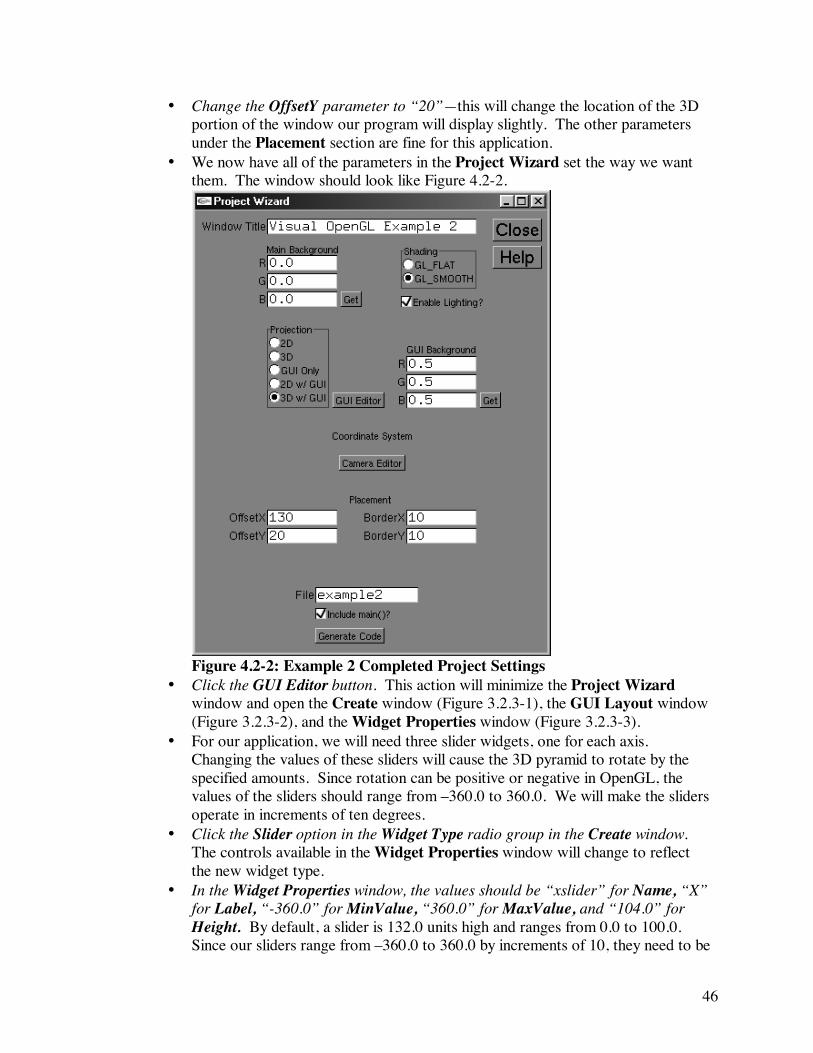
• Change the OffsetY parameter to “20”—this will change the location of the 3D portion of the window our program will display slightly. The other parameters under the Placement section are fine for this application.
• We now have all of the parameters in the Project Wizard set the way we want them. The window should look like Figure 4.2-2.
Figure 4.2-2: Example 2 Completed Project Settings
• Click the GUI Editor button. This action will minimize the Project Wizard window and open the Create window (Figure 3.2.3-1), the GUI Layout window (Figure 3.2.3-2), and the Widget Properties window (Figure 3.2.3-3).
• For our application, we will need three slider widgets, one for each axis. Changing the values of these sliders will cause the 3D pyramid to rotate by the specified amounts. Since rotation can be positive or negative in OpenGL, the values of the sliders should range from –360.0 to 360.0. We will make the sliders operate in increments of ten degrees.
• Click the Slider option in the Widget Type radio group in the Create window. The controls available in the Widget Properties window will change to reflect the new widget type.
• In the Widget Properties window, the values should be “xslider” for Name, “X” for Label, “-360.0” for MinValue, “360.0” for MaxValue, and “104.0” for Height. By default, a slider is 132.0 units high and ranges from 0.0 to 100.0. Since our sliders range from –360.0 to 360.0 by increments of 10, they need to be
47
((360.0 – (-360.0))/10.0)+32.0 = 104.0 units high. It is safe to leave the (x, y) location of the slider alone for now.
• Click the Create Widget button in the Create window. A Slider widget will be created in the GUI Layout window according to our specifications.
• Change the values in the Widget Properties window to “yslider” for Name and “Y” for Label, and click the Create Widget button in the Create window again. This will create another slider widget at the same place in the GUI Layout window.
• Change the values in the Widget Properties window to “zslider” for Name and “Z” for Label, and click the Create Widget button in the Create window one last time. A third slider widget will be created in the same place in the GUI Layout window.
• Click the Label option in the Widget Type radio group in the Create window. The Widget Properties window will be updated to reflect this change.
• Change the value in the Widget Properties window to “Rotation” for Label, and click the Create Widget button in the Create window. This action creates a small text label that we will use in our application to make it clear that our sliders control the rotation of the 3D pyramid. At this point, the GUI Layout window should look like Figure 4.2-3.
Figure 4.2-3: The Incomplete GUI
• We now need to arrange the user interface elements to make the application useable. Click and drag the widgets in the GUI Layout window to move them. If multiple widgets are in the same location (as they are here), then whichever one was created last will move along with the mouse while the others will remain where they are. In addition, the X and Y boxes in the Widget Properties window will be updated to reflect the widget’s new position as it is moved.
• Select the X slider in the GUI Layout window. The values in the Widget Properties window will change to match the selected widget’s properties.
48
• Change the values in the Widget Properties window to “25” for X and “10” for Y, and click the Apply button in the Widget Properties window. The X slider will take on the new properties; since only the location was changed, the widget will move to that new location in the GUI Layout window but remain otherwise unchanged.
• Arrange the other widgets. You can either type the coordinates directly or drag the widgets using the mouse. The finished GUI should look something like Figure 4.2-4.
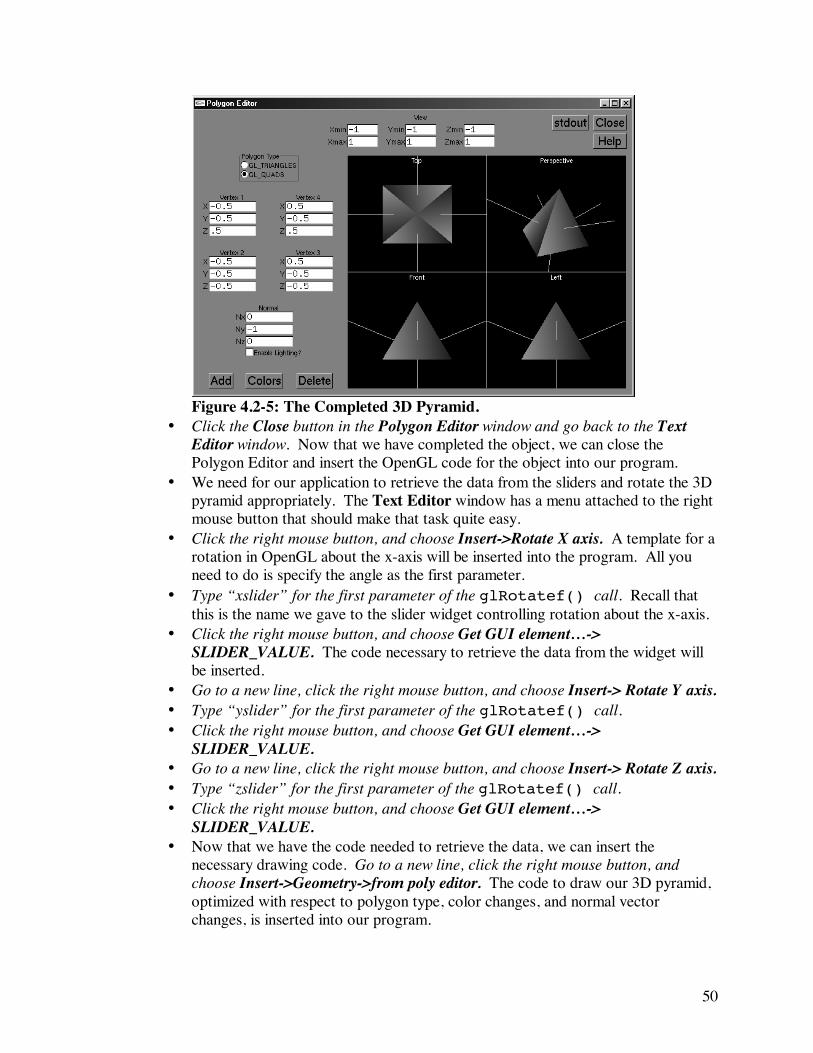
Figure 4.2-4: The completed GUI.
• Click the Close button in the Create window. This closes the GUI Editor windows and restores the Project Wizard window.
• Click the Camera Editor button in the Project Wizard window. The Camera Editor window, shown in Figure 3.2.4-1, will appear. You can use the Camera Editor to set up the camera for your 3D OpenGL applications. A spinning reference object, the position and size of which can be changed, is provided to help you see the effects of changing the parameters and to get a sense of what settings you should use for your own scene.
• Change the values in the Camera Editor window to “20.0” for FarClip and “2.0” for Camera Position Z. The 3D pyramid we are going to draw is only a unit large, thus the camera should be moved closer than the default of (0, 0, 10) to get a better view. The far clipping plane specifies that anything farther away from the camera than its value will not be seen. For our small scene, 20.0 units should be sufficient. The other Projection settings and the Camera Target settings are already set to appropriate values for our application.
• Click the Close button in the Camera Editor window. We now have the camera set up like we wish for our project, so we no longer need it.
• Click the Generate Code button in the Project Wizard window, and then click the Close button in the Project Wizard window. Since we now have all the options set correctly for our project, we can go ahead and generate the template program
49
and move the Project Window out of the way. Our code will appear in the Text Editor window, similar to Figure 4.1-3.
• Adjust the Text Editor to a comfortable size, and scroll down to find the comment that says INSERT YOUR DRAWING CODE HERE. In a little while, we will come back and add the necessary code here, but first, we will create the geometry.
• Click the Polygon Editor button in the Visual OpenGL window. This action brings up the Polygon Editor window, shown in Figure 3.2.5-1.
• Click the Colors button in the Polygon Editor window. This action brings up a window that allows you to set the color for each vertex of the current polygon. You can use the Color Picker to choose these values or type them directly. Set the color for Vertex 1 to red (1.0, 0.0, 0.0), the color for Vertex 2 to green (0.0, 1.0, 0.0), and the color for Vertex 3 to blue (0.0, 0.0, 1.0). Click the Close button in the Vertex Colors window. Changing the colors in this way makes our geometry look more interesting.
• Change the values in the View area to “-1.0” for Xmin, Ymin, and Zmin, and to “1.0” for Xmax, Ymax, and Zmax. Changing these values will give us a better view of the object we are going to create.
• Change Vertex 1 to (0.0, 0.5, 0.0). Change Vertex 2 to (-0.5, -0.5, 0.5). Change Vertex 3 to (0.5, -0.5, 0.5). Notice that the appropriate normal vector for this polygon is automatically calculated.
• Click the Add button. This action commits the current polygon to memory and creates a new one with the same parameters.
• Change Vertex 2 to (0.5, -0.5, 0.5). Change Vertex 3 to (0.5, -0.5, -0.5). • Click the Add button. • Change Vertex 2 to (0.5, -0.5, -0.5). Change Vertex 3 to (-0.5, -0.5, -0.5). • Click the Add button. • Change Vertex 2 to (-0.5, -0.5, -0.5). Change Vertex 3 to (-0.5, -0.5, 0.5). • Click the Add button. • Change the Polygon Type to GL_QUADS. So far our object has four sides, each
made of a triangle. We need a bottom for the object so it will be completely enclosed, thus giving the illusion that it is solid.
• Change Vertex 1 to (-0.5, -0.5, 0.5). Change Vertex 2 to (-0.5, -0.5, -0.5). Change Vertex 3 to (0.5, -0.5, -0.5). Change Vertex 4 to (0.5, -0.5, 0.5). Our 3D pyramid is now complete. At this point, the Polygon Editor window should look like Figure 4.2-5.
50
Figure 4.2-5: The Completed 3D Pyramid.
• Click the Close button in the Polygon Editor window and go back to the Text Editor window. Now that we have completed the object, we can close the Polygon Editor and insert the OpenGL code for the object into our program.
• We need for our application to retrieve the data from the sliders and rotate the 3D pyramid appropriately. The Text Editor window has a menu attached to the right mouse button that should make that task quite easy.
• Click the right mouse button, and choose Insert->Rotate X axis. A template for a rotation in OpenGL about the x-axis will be inserted into the program. All you need to do is specify the angle as the first parameter.
• Type “xslider” for the first parameter of the glRotatef() call. Recall that this is the name we gave to the slider widget controlling rotation about the x-axis.
• Click the right mouse button, and choose Get GUI element…-> SLIDER_VALUE. The code necessary to retrieve the data from the widget will be inserted.
• Go to a new line, click the right mouse button, and choose Insert-> Rotate Y axis. • Type “yslider” for the first parameter of the glRotatef() call. • Click the right mouse button, and choose Get GUI element…->
SLIDER_VALUE. • Go to a new line, click the right mouse button, and choose Insert-> Rotate Z axis. • Type “zslider” for the first parameter of the glRotatef() call. • Click the right mouse button, and choose Get GUI element…->
SLIDER_VALUE. • Now that we have the code needed to retrieve the data, we can insert the
necessary drawing code. Go to a new line, click the right mouse button, and choose Insert->Geometry->from poly editor. The code to draw our 3D pyramid, optimized with respect to polygon type, color changes, and normal vector changes, is inserted into our program.
51
• Click the Save button in the Text Editor window. The updated program will be written to disk. You can now compile and run the program on your system.
52
5 Conclusions and Future Work This report has presented the design and implementation of an integrated
development environment for OpenGL. This environment, called Visual OpenGL, provides graphical interfaces to some of the more visual aspects of OpenGL development, all of which were covered in detail. Also, it enhances the ability of users to interact with OpenGL applications by providing a system-independent library of some of the most common graphical user interface elements. This library was also discussed at great length. The resulting application is made up of several smaller utilities that can be used individually or in combination with each other to produce a full application. Finally, the report gave two detailed examples of how to use Visual OpenGL.
Overall, Visual OpenGL appears useful to students who are beginning to learn
OpenGL, especially students who may have only a cursory understanding of programming concepts, such as students from other departments. Visual OpenGL also appears useful to seasoned OpenGL developers. It eliminates a lot of the uncertainty with which one can be faced during development and saves time by automatically generating an appropriate template program based on the needs of the application. Even if one already has a template program written for his application, he can use Visual OpenGL to help add additional code to it, such as color changes and additional geometry.
While Visual OpenGL is useful for developing relatively simple OpenGL
applications, there are improvements that can be made and additional work that can be done to make the system even better. More user interface types could be added to the GUI library, and the appearance and behavior of the ones currently in the library could likely be improved. Some of the utilities could be made more advanced. For example, the ability to use the mouse to place the camera interactively or to draw polygons directly would be quite useful. Advanced options in the Project Wizard and additional utilities to assist with those options could be added; for example, more advanced lighting options and perhaps even texture mapping could be included. Finally, the ability to parse existing OpenGL programs, check for syntax errors in those programs, and extract geometry from those programs would be quite useful to all OpenGL developers.
53
References [1] T. Davis, J. Neider, D. Shreiner, and M. Woo. OpenGL Programming Guide: The
Official Guide to Learning OpenGL, Version 1.2. Addison-Wesley, 1999. [2] Kilgard, Mark J. The OpenGL Utility Toolkit (GLUT) Programming Interface
API Version 3. http://www.opengl.org/developers/documentation/glut/spec3/spec3.html
[3] Feiner, Foley, Hughes, van Dam. Computer Graphics: Principles and Practice. Addison-Wesley, 1997.