Visualization of Submerged Arc Welding Phenomena by X-ray Observation and Direct Observation Hisaya Komen a* , Yohei Abe b , Takahiro Fujimoto b , Masaya Shigeta a , Mitsuyoshi Nakatani b and Manabu Tanaka a a Joining and Welding Research Institute, Osaka University, Osaka, Japan b Hitachi Zosen corporation, Osaka, Japan Behaviors of flux, slag and molten metal during a submerged arc welding with a large current were observed by the X-ray observation system including a high speed video camera. Moreover, the direct observation using a high speed video camera was also carried out to observe the arc phenomena, which could not be observed by the X-ray observation. From X-ray observation results, the weld part during a submerged arc welding was classified broadly into 4 regions. Then, it was clarified that a slag was pushed backward in a welding direction when it approached to a wire which an arc plasma existed around. As a result of this series of slag behaviors, the preformed cavity was filled by the slag at the backward of the heat source. In addition, from a direct observation, it was made clear that there were bluish white plasma at beneath a molten metal droplet and orange emitting region around the plasma. Key Words: Submerged arc welding, X-ray observation, Droplet transfer phenomena 1. INTRODUCTION Submerged arc welding (SAW) is a welding process in which large current can be used. This process is applied to large constructions such as bridges, ships and so on. In this welding, a weld part including a wire and a base metal surface is covered with powder flux and slag, which protect the weld part from air. Moreover, it also has an advantage that amounts of generation of fume and spatters are smaller than other welding processes. On the other hand, observation of these welding phenomena during this welding from outside is difficult since the weld part is covered with flux. Because of difficulty of the observation and multiple compositions of flux, understanding of this welding process is insufficient. In addition, since high performance welding power sources that can control its waveform precisely have been developed, number of welding parameters for the SAW is increased. To control this welding process using those welding parameters, understanding of the welding phenomena is necessary. Therefore, some researchers have recently tried to visualize the welding phenomena by direct observation. Mendez et al. 1) and Gött et al. 2) set a tunnel in a direction perpendicular to a weld line. They observed molten metal droplets while a wire is traversed in the tunnel. As a result, they successfully observed the molten metal droplet transfer phenomena inside of a space which was called cavity and formed by the evaporation of fluxes. Moreover, Li et al. 3) also directly observed SAW phenomena. In their study, molten metal droplet transfer phenomena were observed with a laser as a light source when a wire was traversed in a tunnel which was set in a direction perpendicular to the weld line. These experimental observation results were significant knowledges for understanding the SAW phenomena which have been unknown so far. However, it was unknown whether the observed phenomena in these experimental methods were equivalent to actual phenomena or not. On the other hand, X-ray observation is one of experimental methods to observe SAW phenomena without destructing an environment in a cavity. Although there were some previous studies using the X-ray observation 4) , they could not observe the welding phenomena at a high frame rate. Therefore, the actual welding phenomena have not been clarified yet. In this study, behaviors of flux, slag and molten metal during an SAW with a large current were observed by the X-ray observation system including a high speed video camera. Moreover, a direct observation using a high speed video camera was also carried out to observe the arc phenomena, which cannot be observed by the X-ray observation. 2. EXPERIMENTAL SETUP 2.1 X-ray observation system Figure 1 shows a photograph of the X-ray observation system. This system was composed of two sets of an X-ray source, an intensifier and a high speed video camera. In this study, one set of them was used for the observation. Fig. 1 Appearance of X-ray observation system. received: 2018.10.31; accepted: 2018.12.3 *Corresponding author E-mail address: [email protected]Welding Letters Welding Letters Vol.36 No.4 (2018) p.9 WL –12 WL
Transcript
Visualization of Submerged Arc Welding Phenomenaby X-ray Observation and Direct Observation
a Joining and Welding Research Institute, Osaka University, Osaka, Japanb Hitachi Zosen corporation, Osaka, Japan
Behaviors of flux, slag and molten metal during a submerged arc welding with a large current were observed by the X-ray observation system including a high speed video camera. Moreover, the direct observation using a high speed video camera was also carried out to observe the arc phenomena, which could not be observed by the X-ray observation. From X-ray observation results, the weld part during a submerged arc welding was classified broadly into 4 regions. Then, it was clarified that a slag was pushedbackward in a welding direction when it approached to a wire which an arc plasma existed around. As a result of this series of slag behaviors, the preformed cavity was filled by the slag at the backward of the heat source. In addition, from a direct observation, it was made clear that there were bluish white plasma at beneath a molten metal droplet and orange emitting region around the plasma.
Key Words: Submerged arc welding, X-ray observation, Droplet transfer phenomena
1. INTRODUCTION
Submerged arc welding (SAW) is a welding process in which large current can be used. This process is applied to large constructions such as bridges, ships and so on. In this welding, a weld part including a wire and a base metal surface is covered with powder flux and slag, which protect the weld part from air. Moreover, it also has an advantage that amounts of generation of fume and spatters are smaller than other welding processes. On the other hand, observation of these welding phenomena during this welding from outside is difficult since the weld part is covered with flux. Because of difficulty of the observation and multiple compositions of flux, understanding of this welding process is insufficient. In addition, since high performance welding power sources that can control its waveform precisely have been developed, number of welding parameters for the SAW is increased. To control this welding process using those welding parameters, understanding of the welding phenomena is necessary. Therefore, some researchers have recently tried to visualize the welding phenomena by direct observation.
Mendez et al.1) and Gött et al.2) set a tunnel in a direction perpendicular to a weld line. They observed molten metal droplets while a wire is traversed in the tunnel. As a result, they successfully observed the molten metal droplet transfer phenomena inside of a space which was called cavity and formed by the evaporation of fluxes. Moreover, Li et al.3) also directly observed SAW phenomena. In their study, molten metal droplet transfer phenomena were observed with a laser as a light source when a wire was traversed in a tunnel which was set in a direction perpendicular to the weld line. These experimental observation results were significant
knowledges for understanding the SAW phenomena which have been unknown so far. However, it was unknown whether the observed phenomena in these experimental methods were equivalent to actual phenomena or not. On the other hand, X-ray observation is one of experimental methods to observe SAW phenomena without destructing an environment in a cavity. Although there were some previous studies using the X-ray observation4), they could not observe the welding phenomena at a high frame rate. Therefore, the actual welding phenomena have not been clarified yet. In this study, behaviors of flux, slag and molten metal during an SAW with a large current were observed by the X-ray observation system including a high speed video camera. Moreover, a direct observation using a high speed video camera was also carried out to observe the arc phenomena, which cannot be observed by the X-ray observation.
2. EXPERIMENTAL SETUP
2.1 X-ray observation system
Figure 1 shows a photograph of the X-ray observation system. This system was composed of two sets of an X-ray source, an intensifier and a high speed video camera. In this study, one set of them was used for the observation.
Fig. 1 Appearance of X-ray observation system.received: 2018.10.31; accepted: 2018.12.3
Figure 2 shows a schematic illustration of the experimental setup. By setting an X-ray source, an intensifier and a high speed video camera in a direction perpendicular to the weld line, welding phenomena were captured as two-dimensional images. Tube current and tube voltage of the X-ray source were set to be 125 kV and 6 mA, respectively. Moreover, a welding current waveform, an arc voltage waveform and a trigger signal for a high speed video camera were measured by a logger simultaneously. The frame rate was set to be 3000 fps and the exposure time was set to be 331 s.
Fig. 2 Schematic illustration of experimental arrangement to observe inside of the weld part in an SAW.
2.2 Direct observation
Figure 3 shows a schematic illustration of experimental setup for the direct observation. A steel tube was inserted into flux to see inside of a cavity. Fig. 4 shows a magnified figure around a weld part. The tube was inclined about 17 degrees angle for the base metal surface to prevent the slag inflow. CO2 gas was flowed in the cavity from the tubeabout 35 L/min to keep pressure inside of it following previous studies1, 2). The inside of the cavity was observed by high speed video camera during the time a wire traversed in front of the tube. The frame rate and the exposure time were set to be 3000 fps and 5 s, respectively. In addition, neutral density filters were set in front of a camera lens to reduce amount of light from an arc about 1/64.
Fig. 3 Schematic illustration of experimental setupfor direct observation.
Fig. 4 Magnified figure around weld part.
2.3 Welding conditions
Table 1 shows the welding conditions. 2.25Cr-1Mo steel whose size was 400 mm×50 mm×20 mmt was used as a base metal. JIS Z3351 YS-2CM2 whose diameter was 4 mm was used as a wire and JIS Z3352 SACG1 which was one of the bond fluxes was also used. Height of the flux was set to be about 30 mm that was the same as CTWD.
Table 1 Welding conditions for X-ray and direct observations.
Welding current 600 AArc voltage 33 VWelding speed 5 mm/sCTWD 30 mmPolarity of the welding current DCEP
3. RESULTS AND DISCUSSION
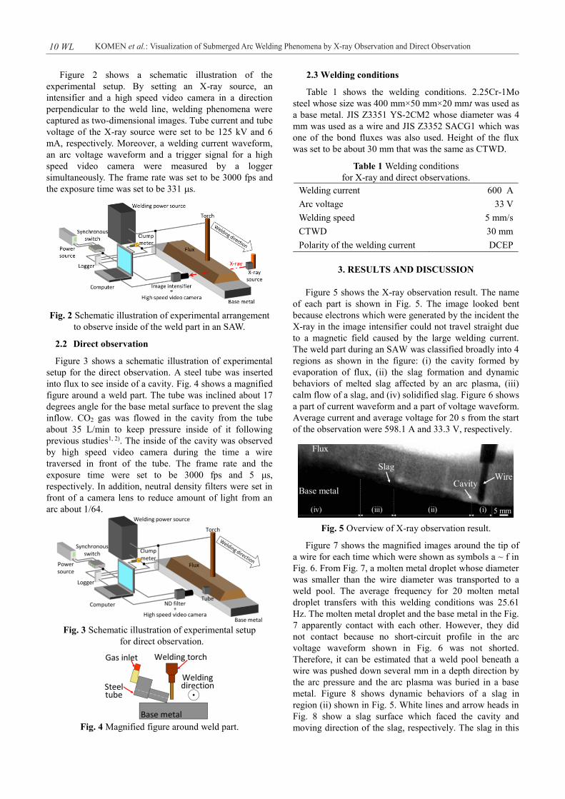
Figure 5 shows the X-ray observation result. The name of each part is shown in Fig. 5. The image looked bent because electrons which were generated by the incident the X-ray in the image intensifier could not travel straight due to a magnetic field caused by the large welding current. The weld part during an SAW was classified broadly into 4 regions as shown in the figure: (i) the cavity formed by evaporation of flux, (ii) the slag formation and dynamic behaviors of melted slag affected by an arc plasma, (iii) calm flow of a slag, and (iv) solidified slag. Figure 6 shows a part of current waveform and a part of voltage waveform. Average current and average voltage for 20 s from the start of the observation were 598.1 A and 33.3 V, respectively.
Fig. 5 Overview of X-ray observation result.
Figure 7 shows the magnified images around the tip of a wire for each time which were shown as symbols a ~ f in Fig. 6. From Fig. 7, a molten metal droplet whose diameter was smaller than the wire diameter was transported to a weld pool. The average frequency for 20 molten metal droplet transfers with this welding conditions was 25.61 Hz. The molten metal droplet and the base metal in the Fig. 7 apparently contact with each other. However, they did not contact because no short-circuit profile in the arc voltage waveform shown in Fig. 6 was not shorted. Therefore, it can be estimated that a weld pool beneath a wire was pushed down several mm in a depth direction by the arc pressure and the arc plasma was buried in a base metal. Figure 8 shows dynamic behaviors of a slag in region (ii) shown in Fig. 5. White lines and arrow heads in Fig. 8 show a slag surface which faced the cavity and moving direction of the slag, respectively. The slag in this
KOMEN et al.: Visualization of Submerged Arc Welding Phenomena by X-ray Observation and Direct Observation10 WL
region was pushed backward in a welding direction when it approached to a wire which an arc plasma existed around (Fig. 8(a) ~ Fig. 8(c)). Then, the preformed cavity was filled by the slag at the backward of the arc. After that, the slag flows to the arc, whose behavior was like the waviness (Fig. 8(d) ~ Fig. 8(f)). The slag in region (ii) repeated those behaviors during the welding which were explained above. Then, the slag behaviors became small as the heat source travelled, and the slag was finally solidified.
Fig. 6 Current waveform (up) and voltage waveform (down) in X-ray observation.
Figure 9 shows the arc appearance during one droplet transfer in an SAW obtained by the direct observation. A molten metal droplet was formed at tip of wire (Fig. 9(a) ~Fig. 9(c)), it was pinched at middle of the droplet (Fig. 9(d)~ Fig. 9(g)). Finally, the droplet was detached from tip of a wire (Fig. 9(h)). The average frequency for 20 molten metal droplet transfers with this welding conditions was 23.55 Hz. During the droplet transfer, there was bluish white plasma at beneath a molten metal droplet like a globular transfer. Moreover, there was also orange emitting regions around the plasma. The previous study1) suggested that the gas which was flowed artificially from outside to keep a pressure in a cavity did not become a plasma. Then, it was also suggested that an atmosphere inside a cavity was composed of CO2
1) or CO5). Therefore, bluish white plasma was composed of the metal vapor, CO2 and CO in the cavity. In standard CO2 gas welding, the plasma did not emit the light whose color was the range from orange to red6). So it is suggested that the orange bright region around the bluish white plasma was generated from flux and slag. Focusing on the positional relationship similarly to X-ray observation, the arc plasma was kept beneath a droplet like the standard CO2 gas welding. Although the positional relationship between arc plasma and molten metal droplet was similar to a globular transfer, molten metal droplet whose diameter was smaller than a wire diameter was detached from the tip of a wire like a spray
transfer. This is because a current density in a molten metal droplet and the Lorentz force acting on the droplet became smaller since a wire diameter for an SAW was larger than that for a gas metal arc welding. The plasma flow caused by the Lorentz force became smaller due to the decrease of the force. So, it could be considered that the molten metal droplet was easily detached by reducing the plasmapressure under the droplet. Finally, Fig. 10 shows the current waveform and the voltage waveform during this direct observation. t = 0 s was the time at which a wire started to course in front of the steel tube, which was also equivalent to the camera trigger. From these waveforms, although an environment in a cavity was affected by the tube and CO2 gas inflow, it was checked that the welding current and the arc voltage during the wire coursed in front of a steel tube were similar to them before the wire reached to the tube.
(a) t = 0.0310 s (b) t = 0.0400 s (c) t = 0.0427 s
(d) t = 0.0430 s (e) t = 0.0440 s (f) t = 0.0443 sFig. 7 X-ray observation results in a droplet transfer.
(a) t = 0 s (b) t = 0.0337 s
(c) t = 0.0530 s (d) t = 0.1303 s
(e) t = 0.1713 s (f) t = 0.2183 sFig. 8 Slag behaviors in region (ii) with time evolution.
Figure 2 shows a schematic illustration of the experimental setup. By setting an X-ray source, an intensifier and a high speed video camera in a direction perpendicular to the weld line, welding phenomena were captured as two-dimensional images. Tube current and tube voltage of the X-ray source were set to be 125 kV and 6 mA, respectively. Moreover, a welding current waveform, an arc voltage waveform and a trigger signal for a high speed video camera were measured by a logger simultaneously. The frame rate was set to be 3000 fps and the exposure time was set to be 331 s.
Fig. 2 Schematic illustration of experimental arrangement to observe inside of the weld part in an SAW.
2.2 Direct observation
Figure 3 shows a schematic illustration of experimental setup for the direct observation. A steel tube was inserted into flux to see inside of a cavity. Fig. 4 shows a magnified figure around a weld part. The tube was inclined about 17 degrees angle for the base metal surface to prevent the slag inflow. CO2 gas was flowed in the cavity from the tubeabout 35 L/min to keep pressure inside of it following previous studies1, 2). The inside of the cavity was observed by high speed video camera during the time a wire traversed in front of the tube. The frame rate and the exposure time were set to be 3000 fps and 5 s, respectively. In addition, neutral density filters were set in front of a camera lens to reduce amount of light from an arc about 1/64.
Fig. 3 Schematic illustration of experimental setupfor direct observation.
Fig. 4 Magnified figure around weld part.
2.3 Welding conditions
Table 1 shows the welding conditions. 2.25Cr-1Mo steel whose size was 400 mm×50 mm×20 mmt was used as a base metal. JIS Z3351 YS-2CM2 whose diameter was 4 mm was used as a wire and JIS Z3352 SACG1 which was one of the bond fluxes was also used. Height of the flux was set to be about 30 mm that was the same as CTWD.
Table 1 Welding conditions for X-ray and direct observations.
Welding current 600 AArc voltage 33 VWelding speed 5 mm/sCTWD 30 mmPolarity of the welding current DCEP
3. RESULTS AND DISCUSSION
Figure 5 shows the X-ray observation result. The name of each part is shown in Fig. 5. The image looked bent because electrons which were generated by the incident the X-ray in the image intensifier could not travel straight due to a magnetic field caused by the large welding current. The weld part during an SAW was classified broadly into 4 regions as shown in the figure: (i) the cavity formed by evaporation of flux, (ii) the slag formation and dynamic behaviors of melted slag affected by an arc plasma, (iii) calm flow of a slag, and (iv) solidified slag. Figure 6 shows a part of current waveform and a part of voltage waveform. Average current and average voltage for 20 s from the start of the observation were 598.1 A and 33.3 V, respectively.
Fig. 5 Overview of X-ray observation result.
Figure 7 shows the magnified images around the tip of a wire for each time which were shown as symbols a ~ f in Fig. 6. From Fig. 7, a molten metal droplet whose diameter was smaller than the wire diameter was transported to a weld pool. The average frequency for 20 molten metal droplet transfers with this welding conditions was 25.61 Hz. The molten metal droplet and the base metal in the Fig. 7 apparently contact with each other. However, they did not contact because no short-circuit profile in the arc voltage waveform shown in Fig. 6 was not shorted. Therefore, it can be estimated that a weld pool beneath a wire was pushed down several mm in a depth direction by the arc pressure and the arc plasma was buried in a base metal. Figure 8 shows dynamic behaviors of a slag in region (ii) shown in Fig. 5. White lines and arrow heads in Fig. 8 show a slag surface which faced the cavity and moving direction of the slag, respectively. The slag in this
Welding Letters Vol.36 No.4 (2018) 11 WL
(a) t = 3.0203 s (b) t = 3.0367 s
(c) t = 3.0387 s (d) t = 3.0420 s
(e) t = 3.0427 s (f) t = 3.0437 s
(g) t = 3.0443 s (h) t = 3.0450 sFig. 9 Arc appearances during one droplet transfer.
Fig. 10 Current waveform (up) and voltage waveform (down) in direct observation.
4. CONCLUSIONS
Dynamic behaviors of molten metal droplet, slag, fluxand arc plasma were successfully observed by X-ray observation and direct observation. The conclusions of this study are summarized as follows: [1] From the X-ray observation, the weld part during an
SAW was classified into 4 regions, which were (i) the cavity foaming by evaporation of a flux, (ii) the slag formation and dynamic behaviors of melted slag affected by an arc plasma, (iii) calm flow of a slag, and (iv) solidified slag.
[2] It was clarified that a slag was pushed backward in a welding direction when it approached to a wire which an arc plasma existed around. As a result of this series of slag behaviors, the preformed cavity was filled by the slag at the backward of the heat source.
[3] From the direct observation results, it was made clear that there were bluish white plasma beneath a molten metal droplet and orange emitting region around the plasma.
[4] Although the positional relationship between arc plasma and molten metal droplet was similar to a globular transfer, molten metal droplet whose diameter was smaller than the wire diameter was detached from the tip of the wire. This was because the current density in the droplet and the Lorentz force acting on the droplet became smaller since a wire diameter for an SAW was larger than it for a gas metal arc welding. So, the plasma flow caused by the Lorentz force became smaller due to the decrease of the force. Then, it could be considered that molten metal droplet was easily detached by reducing the pressure increase under the droplet.
References
2) G. Gött, A. Gericke, K. M. Henkel and D. Uhrlandt: Optical and Spectroscopic Study of a Submerged Arc Welding Cavern, Weld. J., 95-12 (2016), 491s-499s.
3) K. Li, Z. Wu, Y. Zhu and C. Liu: Metal transfer in submerged arc welding, J. of Mater. Process. Technol., 244 (2017), 314-319.
4) K. Akahide, T. Ukibe and J. Tsuboi: Correlation between Arc Phenomena and Welding Parameters in Submerged-Arc Welding, J. of the Jpn Weld. Soc., 50-5 (1981), 520-524 (in Japanese).
5) H. Terashima, N. Nishiyama and J. Tsuboi: Influence of Slag Basicity on Deoxidation in Submerged-Arc Welding -Deoxidation in Submerged-Arc Welding (Report 1)-, J. of the Jpn Weld. Soc., 46-3 (1977), 165-171 (in Japanese).
6) T. Methong: Influence of rare earth metal added to electrode on plasma characteristics in gas metal arc welding, Ph. D. Thesis, Osaka University, (2015), Osaka.
1) P. F. Mendez, G. Goett and S. D. Guest: High Speed Video of Metal Transfer in Submerged Arc Welding, Weld. J., 94-10 (2015), 325s-332s.
KOMEN et al.: Visualization of Submerged Arc Welding Phenomena by X-ray Observation and Direct Observation12 WL