51
TRANSLATE for CATIA V5 - JT USER GUIDE Revision: 1.0 Issued: 27/03/2019 © THEOREM SOLUTIONS 2020

TRANSLATE for CATIA V5 - JT
USER GUIDE
Revision: 1.0
Issued: 27/03/2019
© THEOREM SOLUTIONS 2020
TRANSLATE for CATIA V5 - JT
1 | P a g e ©Theorem Solutions 2020
Contents
Overview of TRANSLATE ............................................................................................................ 3
About Theorem ......................................................................................................................3
Theorem’s Product Suite ........................................................................................................4
The CATIA V5 Bi-directional JT Translator ..............................................................................5
Primary Product Features .......................................................................................................5
Primary Product benefits? ......................................................................................................6
Getting Started .......................................................................................................................... 7
Documentation & Installation Media .....................................................................................7
Installation ..............................................................................................................................7
License Configuration .............................................................................................................7
Using the Product ...................................................................................................................7
Using the Product ...................................................................................................................... 8
Default Translations ...............................................................................................................8
Default Translation – via the Unified Interface ..................................................................8
Default Translation – via the Command Line .................................................................. 10
Translator Customization ........................................................................................................ 11
Common Options for CATIA V5 to JT ................................................................................... 11
CATIA V5 Read Arguments .............................................................................................. 11
JT Write Arguments ......................................................................................................... 13
CATIA V5 to JT Entity Masking Arguments ...................................................................... 14
CATIA V5 to JT General Arguments ................................................................................. 15
Processing CATIA V5 FTA data to JT PMI ......................................................................... 16
Options for Processing FTA Data with Filled Text............................................................ 16
Options for Processing FTA Data using Outline Text ....................................................... 19
Common Options for JT to CATIA V5 ................................................................................... 20
JT Read Arguments .......................................................................................................... 20
CATIA V5 Write Arguments ............................................................................................. 22
JT to CATIA V5 General Arguments ................................................................................. 23

TRANSLATE for CATIA V5 - JT
2 | P a g e ©Theorem Solutions 2020
Command Line Advanced Arguments ..................................................................................... 24
CATIA V5 Advanced Arguments........................................................................................... 24
JT Advanced Arguments ...................................................................................................... 24
CATIA V5 – JT PDF Add On Products ........................................................................................ 25
Translating Interactively from within CATIA V5 ...................................................................... 25
Save As JT ............................................................................................................................. 26
Open JT Data........................................................................................................................ 27
Appendix A – CATIA V5 Configuration ..................................................................................... 28
Introduction ......................................................................................................................... 28
Conventions ......................................................................................................................... 28
CATIA V5 Installation Directory ........................................................................................... 28
CATIA V5 Environment DIRENV & ENV ................................................................................ 29
Checking the CATIA V5 Environment .................................................................................. 30
Checking the Theorem Shared Library ................................................................................ 30
Appendix B – JT Configuration File .......................................................................................... 31
Introduction ......................................................................................................................... 31
The Setup Section ................................................................................................................ 31
The Level of Detail Section .................................................................................................. 33
The Filter Section ................................................................................................................. 35
The Metadata section .......................................................................................................... 36
The Special Section .............................................................................................................. 37

TRANSLATE for CATIA V5 - JT
3 | P a g e ©Theorem Solutions 2020
Overview of TRANSLATE
About Theorem
Theorem Solutions is a world leader in the field of
Engineering Data Services and Solutions. This
leadership position stems from the quality of our
technology and the people in the company. Quality
comes not only from the skills and commitment of
our staff, but also from the vigorous industrial use of
our technology & services by world leading customers.
We are proud that the vast majority of the world's leading Automotive, Aerospace, Defense,
Power Generation and Transportation companies and their Supply chains use our products
and services daily. Working closely with our customers, to both fully understand their
requirements and feed their input into our development processes has significantly
contributed to our technology and industry knowledge.
Theorem Solutions is an independent UK headquartered company incorporated in 1990,
with sales and support offices in the UK and USA. Theorem has strong relationships with the
major CAD and PLM vendors, including; Autodesk, Dassault Systemes, ICEM Technologies (a
Dassault company), PTC, SolidWorks, Spatial Technology and Siemens PLM Software. These
relationships enable us to deliver best in class services and solutions to engineering
companies worldwide.
TRANSLATE for CATIA V5 - JT
4 | P a g e ©Theorem Solutions 2020
Theorem’s Product Suite
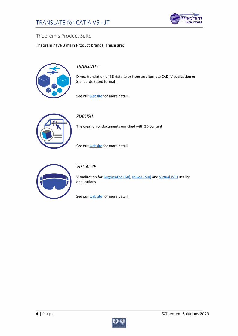
Theorem have 3 main Product brands. These are:
TRANSLATE Direct translation of 3D data to or from an alternate CAD, Visualization or Standards Based format. See our website for more detail.
PUBLISH The creation of documents enriched with 3D content See our website for more detail.
VISUALIZE Visualization for Augmented (AR), Mixed (MR) and Virtual (VR) Reality applications See our website for more detail.
TRANSLATE for CATIA V5 - JT
5 | P a g e ©Theorem Solutions 2020
The CATIA V5 Bi-directional JT Translator
The CATIA V5 to JT translator may be installed on a number of machines each accessing a central network-floating license. The CATIA V5-JT Translator is a bi-directional direct database converter between the Dassault Systèmes CATIA V5 Modelling Application and the JT file format, used by the Siemens Teamcenter Visualization products. It enables the user to convert all forms of 3D Mechanical Design Geometry and Assembly data, together with system defined attribute information, colour information, between these two systems. This product is designed for companies using CATIA V5 who have selected JT to be their main method of collaboration and communication between OEMs and their customers or suppliers. It is also a major method of visualization and therefore companies using JT based solutions need to translate their CATIA V5 data into the JT format. The translator can be invoked in either an interactive or batch mode with the command line interface allowing the conversion process to be integrated into any process oriented operation. Alternatively from Theorem R18 the conversion process may be operated by using the new Theorem Unified Interface.
Primary Product Features
Converts all types of geometry, wire frame, surfaces, trimmed surfaces (faces) and solid models.
Converts assembly structure between both systems.
Converts attribute data including colour and layer information.
Integrated with the CATIA V5 installation.
The conversion process can be run Interactively, Batch Mode or using the new Unified Interface
Command line interface allows process integration.
Data can be filtered by layer and entity type during processing. Geometry can be filtered and selectively processed.
Uses the CATIA V5 API and Siemens JTOpen API to read and write data.
In creating JT files a number of data types can be generated. A facetted representation, a JT Brep definition or an XT Brep definition. As standard a facetted representation is created with the user selecting whether JT or XT Brep definition is created. Converts all types of geometry, wire frame, surfaces, trimmed surfaces (faces) and solid models

TRANSLATE for CATIA V5 - JT
6 | P a g e ©Theorem Solutions 2020
Primary Product benefits?
Being a direct database converter all pre and post processing is eliminated, saving time.
Reduce costs due to processing time and increase overall conversion success levels by filtering input data and focusing the conversion to only those elements required.
Reduce costs and risks associated to accessing the wrong version of data by integrating the conversion process into a related business processes.
With over 20 years of industrial use Theorem translation products robustness and quality is well proven, reducing your business risk.
This document will focus specifically on guidance for the use of the Visualize 3D for CATIA V5 – JT product. For information regarding any of Theorem’s product ranges please contact [email protected]
TRANSLATE for CATIA V5 - JT
7 | P a g e ©Theorem Solutions 2020
Getting Started
Documentation & Installation Media The latest copy of the User Guide documentation can be found on our web site at:
http://www.theorem.com/Documentation
Each product has a specific link that provides user documentation in the form of PDF and
Tutorials.
The latest copy of Theorem software can be found via the link above and by searching for
the specific product. Each product has a specific link to the Product Release Document,
which contains a link to the download location of the installation CD.
Alternatively, you can request a copy of the software to be shipped on a physical CD.
Installation The installation is run from the .msi file download provided. For full details of the installation
process, visit www.theorem.com/documentation and select UI from the product selection
list.
License Configuration To run any product a valid license file is required. The Flex License Manager is run from the
.msi file download provided. For full details of the installation process, visit
www.theorem.com/documentation
Using the Product To use the product, follow the documented steps found in this document or follow the
online video tutorials which can be found from www.theorem.com/documentation
TRANSLATE for CATIA V5 - JT
8 | P a g e ©Theorem Solutions 2020
Using the Product
Default Translations Default Translation – via the Unified Interface The Unified Interface can be started via the Start Menu – if a shortcut was added during
installation.
Alternatively, the Unified Interface can be run via a Windows Explorer selection in:
<UI_installation_directory>\bin\Unified_Interface.cmd
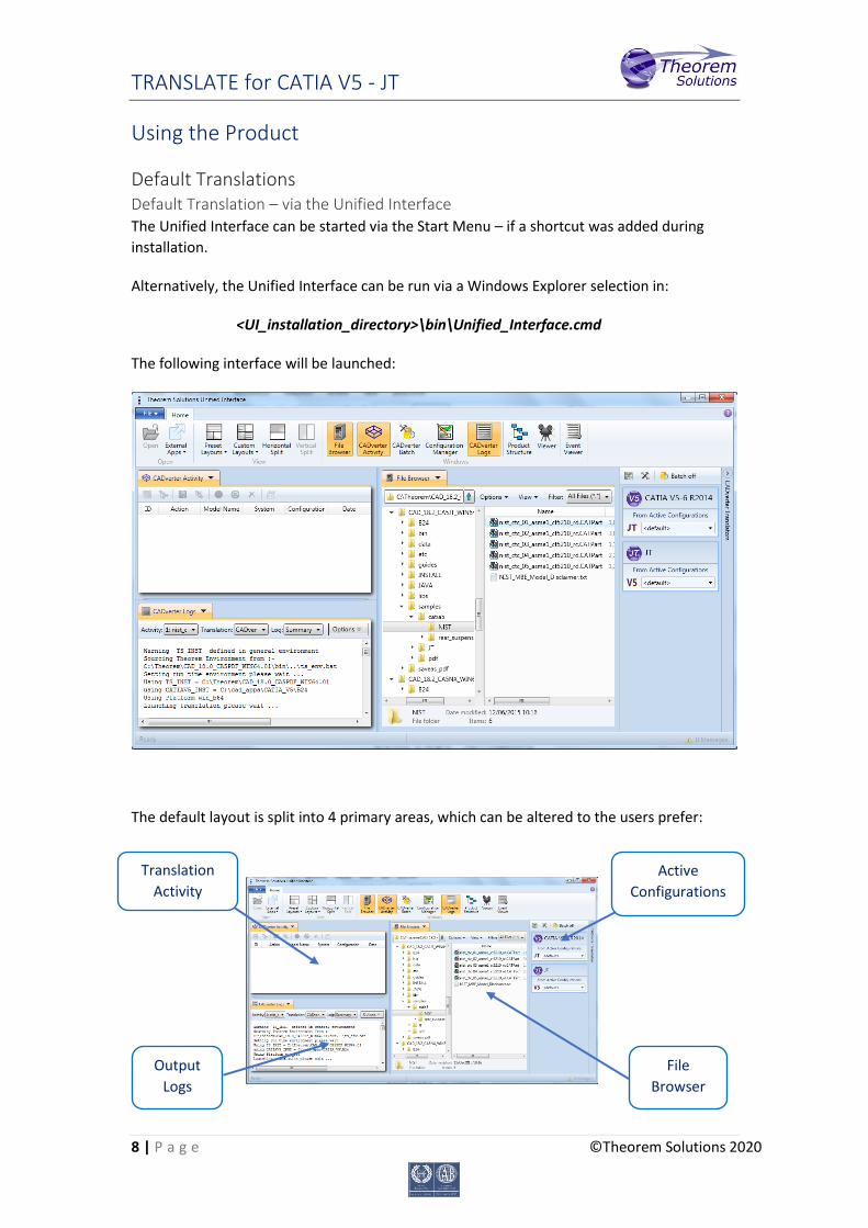
The following interface will be launched:
The default layout is split into 4 primary areas, which can be altered to the users prefer:
File
Browser
Active
Configurations
C
Output
Logs
Translation
Activity
TRANSLATE for CATIA V5 - JT
9 | P a g e ©Theorem Solutions 2020
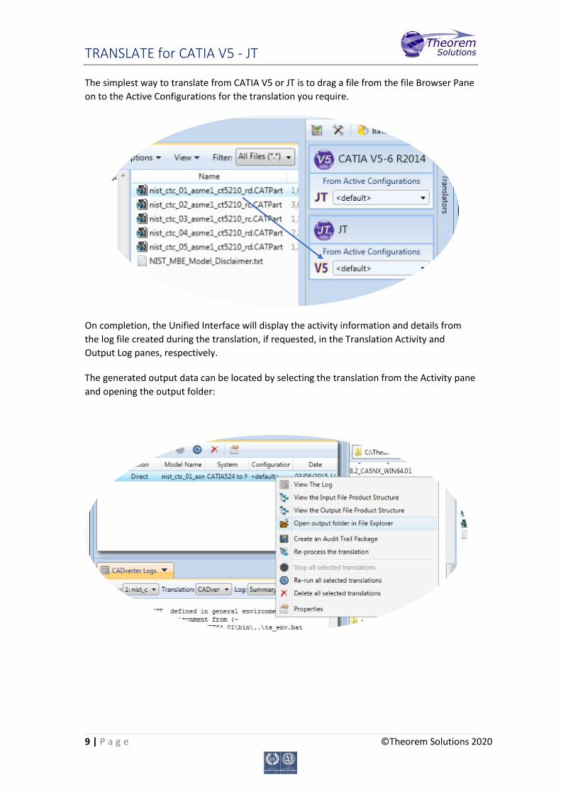
The simplest way to translate from CATIA V5 or JT is to drag a file from the file Browser Pane
on to the Active Configurations for the translation you require.
On completion, the Unified Interface will display the activity information and details from
the log file created during the translation, if requested, in the Translation Activity and
Output Log panes, respectively.
The generated output data can be located by selecting the translation from the Activity pane
and opening the output folder:
TRANSLATE for CATIA V5 - JT
10 | P a g e ©Theorem Solutions 2020
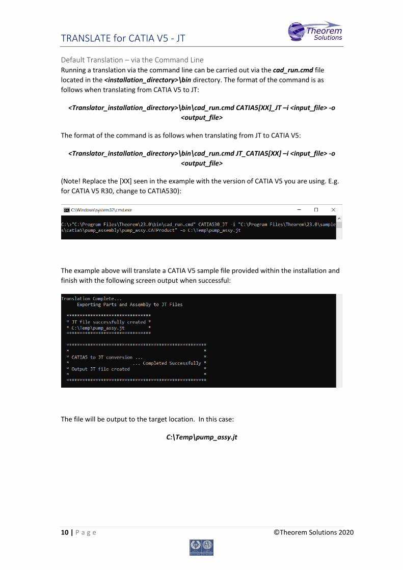
Default Translation – via the Command Line Running a translation via the command line can be carried out via the cad_run.cmd file
located in the <installation_directory>\bin directory. The format of the command is as
follows when translating from CATIA V5 to JT:
<Translator_installation_directory>\bin\cad_run.cmd CATIA5[XX]_JT –i <input_file> -o
<output_file>
The format of the command is as follows when translating from JT to CATIA V5:
<Translator_installation_directory>\bin\cad_run.cmd JT_CATIA5[XX] –i <input_file> -o
<output_file>
(Note! Replace the [XX] seen in the example with the version of CATIA V5 you are using. E.g.
for CATIA V5 R30, change to CATIA530):
The example above will translate a CATIA V5 sample file provided within the installation and
finish with the following screen output when successful:
The file will be output to the target location. In this case:
C:\Temp\pump_assy.jt
TRANSLATE for CATIA V5 - JT
11 | P a g e ©Theorem Solutions 2020
Translator Customization
The Theorem translator allows the information that is read from the source system and
written to the target system to be tailored via a set of user specified arguments. Commonly
used arguments are supported via the Unified Interface, with Advanced Arguments being
described within this document for use in the Unified Interface or via the Command Line
invocation.
Common Options for CATIA V5 to JT Within the Configuration Manager pane of the Unified Interface, arguments that can be
specified when publishing CATIA V5 data into JT are grouped into 4 areas:
CATIA V5 Read – Those arguments that affect how data is read from CATIA V5
JT Write – Those arguments that affect how the data is written to JT
Entity Mask – Those arguments that allow specific read entities to be masked
General – Those arguments that are common to ALL Publishing activities
regardless of source data
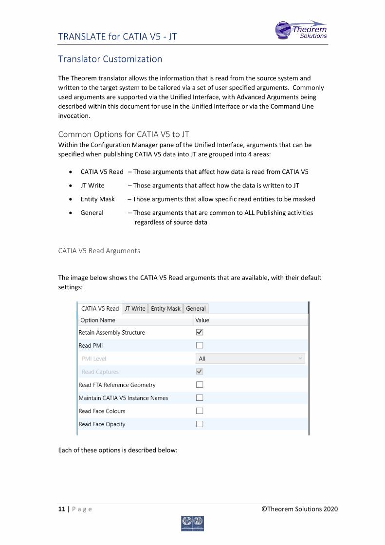
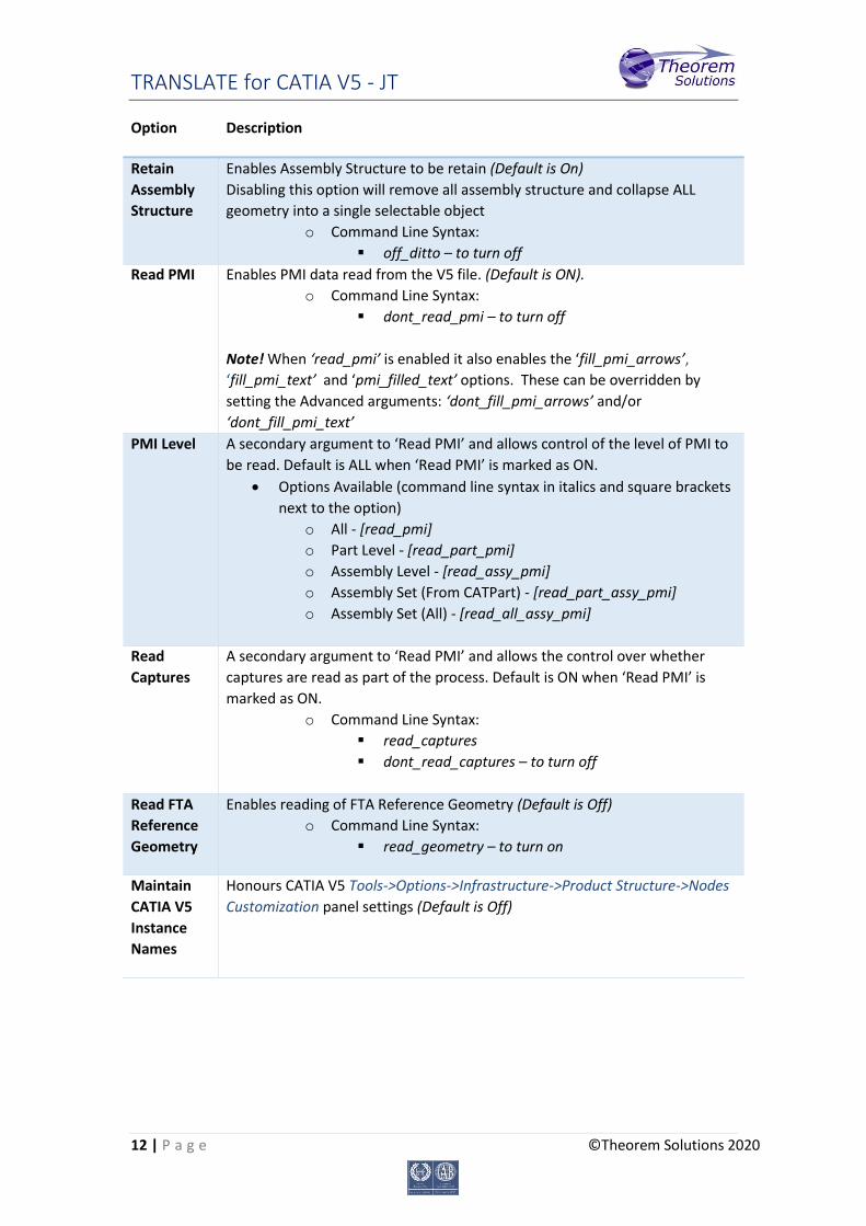
CATIA V5 Read Arguments
The image below shows the CATIA V5 Read arguments that are available, with their default
settings:
Each of these options is described below:
TRANSLATE for CATIA V5 - JT
12 | P a g e ©Theorem Solutions 2020
Option Description
Retain
Assembly
Structure
Enables Assembly Structure to be retain (Default is On)
Disabling this option will remove all assembly structure and collapse ALL
geometry into a single selectable object
o Command Line Syntax:
off_ditto – to turn off
Read PMI Enables PMI data read from the V5 file. (Default is ON).
o Command Line Syntax:
dont_read_pmi – to turn off
Note! When ‘read_pmi’ is enabled it also enables the ‘fill_pmi_arrows’,
‘fill_pmi_text’ and ‘pmi_filled_text’ options. These can be overridden by
setting the Advanced arguments: ‘dont_fill_pmi_arrows’ and/or
‘dont_fill_pmi_text’
PMI Level A secondary argument to ‘Read PMI’ and allows control of the level of PMI to
be read. Default is ALL when ‘Read PMI’ is marked as ON.
Options Available (command line syntax in italics and square brackets
next to the option)
o All - [read_pmi]
o Part Level - [read_part_pmi]
o Assembly Level - [read_assy_pmi]
o Assembly Set (From CATPart) - [read_part_assy_pmi]
o Assembly Set (All) - [read_all_assy_pmi]
Read
Captures
A secondary argument to ‘Read PMI’ and allows the control over whether
captures are read as part of the process. Default is ON when ‘Read PMI’ is
marked as ON.
o Command Line Syntax:
read_captures
dont_read_captures – to turn off
Read FTA
Reference
Geometry
Enables reading of FTA Reference Geometry (Default is Off)
o Command Line Syntax:
read_geometry – to turn on
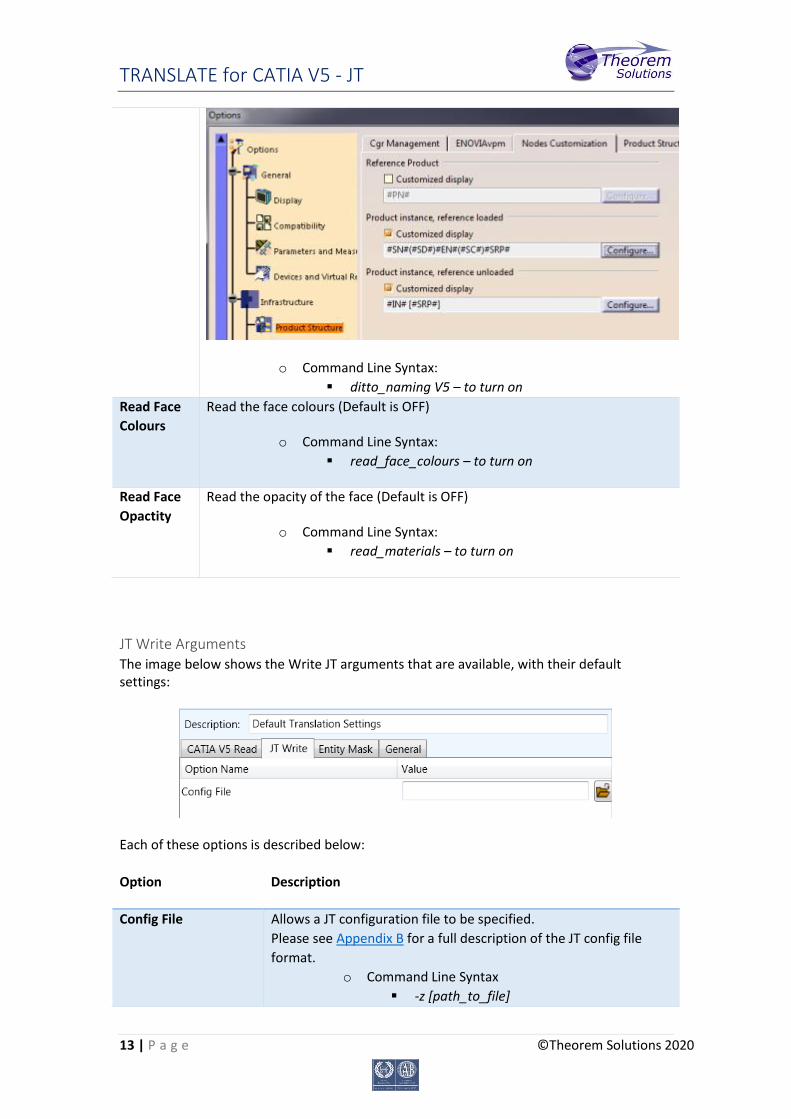
Maintain
CATIA V5
Instance
Names
Honours CATIA V5 Tools->Options->Infrastructure->Product Structure->Nodes
Customization panel settings (Default is Off)
TRANSLATE for CATIA V5 - JT
13 | P a g e ©Theorem Solutions 2020
o Command Line Syntax:
ditto_naming V5 – to turn on
Read Face
Colours
Read the face colours (Default is OFF)
o Command Line Syntax:
read_face_colours – to turn on
Read Face
Opactity
Read the opacity of the face (Default is OFF)
o Command Line Syntax:
read_materials – to turn on
JT Write Arguments The image below shows the Write JT arguments that are available, with their default settings:
Each of these options is described below:
Option Description
Config File Allows a JT configuration file to be specified.
Please see Appendix B for a full description of the JT config file
format.
o Command Line Syntax
-z [path_to_file]

TRANSLATE for CATIA V5 - JT
14 | P a g e ©Theorem Solutions 2020
CATIA V5 to JT Entity Masking Arguments The image below shows the Masking arguments that are available, with their default
settings:
Each of these options is described below:
Option Description
Mask File
Specifies the Mask File to be written to, that can be
referenced by future translations. A Mask file MUST be
specified if masking is required. The first line in this file is OFF
ALL ENT:
o Command Line Syntax:
Mask <filename>
Entity Types Translated Specifies a selection list from which to select which entity
types are to be processed. The following types are available:
"POI","CUR",”SKI”,"SOL",”ISO”,"TEX","AXI"
o Command Line Syntax:
Add any of the above to the specified
mask file, one entry per line prefixed
by the word ON, e.g.:
ON POI
to ensure they are considered in the
translation
Layers Translated Specifies a selection list from which to select which layers are
to be processed.
o Command Line Syntax:
A single entry of ON ALL LAY must
precede any Layer Mask command.
Add a list or range of numbers
representing layer to be processed to
TRANSLATE for CATIA V5 - JT
15 | P a g e ©Theorem Solutions 2020
the specified mask file to ensure they
are NOT considered in the translation
e.g.:
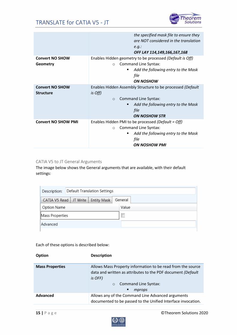
OFF LAY 114,149,166,167,168
Convert NO SHOW
Geometry
Enables Hidden geometry to be processed (Default is Off)
o Command Line Syntax:
Add the following entry to the Mask
file
ON NOSHOW
Convert NO SHOW
Structure
Enables Hidden Assembly Structure to be processed (Default
is Off)
o Command Line Syntax:
Add the following entry to the Mask
file
ON NOSHOW STR
Convert NO SHOW PMI Enables Hidden PMI to be processed (Default = Off)
o Command Line Syntax:
Add the following entry to the Mask
file
ON NOSHOW PMI
CATIA V5 to JT General Arguments The image below shows the General arguments that are available, with their default
settings:
Each of these options is described below:
Option Description
Mass Properties
Allows Mass Property information to be read from the source
data and written as attributes to the PDF document (Default
is OFF)
o Command Line Syntax:
mprops
Advanced Allows any of the Command Line Advanced arguments
documented to be passed to the Unified Interface invocation.
TRANSLATE for CATIA V5 - JT
16 | P a g e ©Theorem Solutions 2020
Processing CATIA V5 FTA data to JT PMI When using the optional CATIA V5 to JT PMI add-on module all CATIA V5 FTA data can be
translated to JT PMI output. This includes the translation of 3D dimensions and annotations
which are mapped to the equivalent JT PMI entities. In addition, CATIA V5 3D sections are
also able to be translated. The CATIA V5 Capture definitions, which manage the visibility of
selective FTA elements as well as the view zoom and orientation, are directly mapped to JT
Model Views.
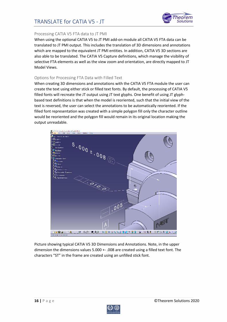
Options for Processing FTA Data with Filled Text When creating 3D dimensions and annotations with the CATIA V5 FTA module the user can
create the text using either stick or filled text fonts. By default, the processing of CATIA V5
filled fonts will recreate the JT output using JT text glyphs. One benefit of using JT glyph-
based text definitions is that when the model is reoriented, such that the initial view of the
text is reversed, the user can select the annotations to be automatically reoriented. If the
filled font representation was created with a simple polygon fill only the character outline
would be reoriented and the polygon fill would remain in its original location making the
output unreadable.
Picture showing typical CATIA V5 3D Dimensions and Annotations. Note, in the upper
dimension the dimensions values 5.000 +- .008 are created using a filled text font. The
characters “ST” in the frame are created using an unfilled stick font.

TRANSLATE for CATIA V5 - JT
17 | P a g e ©Theorem Solutions 2020
Picture showing default JT output of V5 FTA data mapped to JT PMI representation
Picture showing the reorientation of the model with the text also reoriented. Note the text
characters have been rotated 180 degrees and are now readable with filled character
representation.
To recreate the JT filled text using simple polygons, rather than JT text glyph
representations, use the options pmi_glyphs_off pmi_polygons together. The output
representation will appear filled and look correct when viewed in the authored orientation.
However, filled text created with simple polygons, will not display correctly if the data is
reoriented and the text switching in JT is selected. The picture below shows an example of
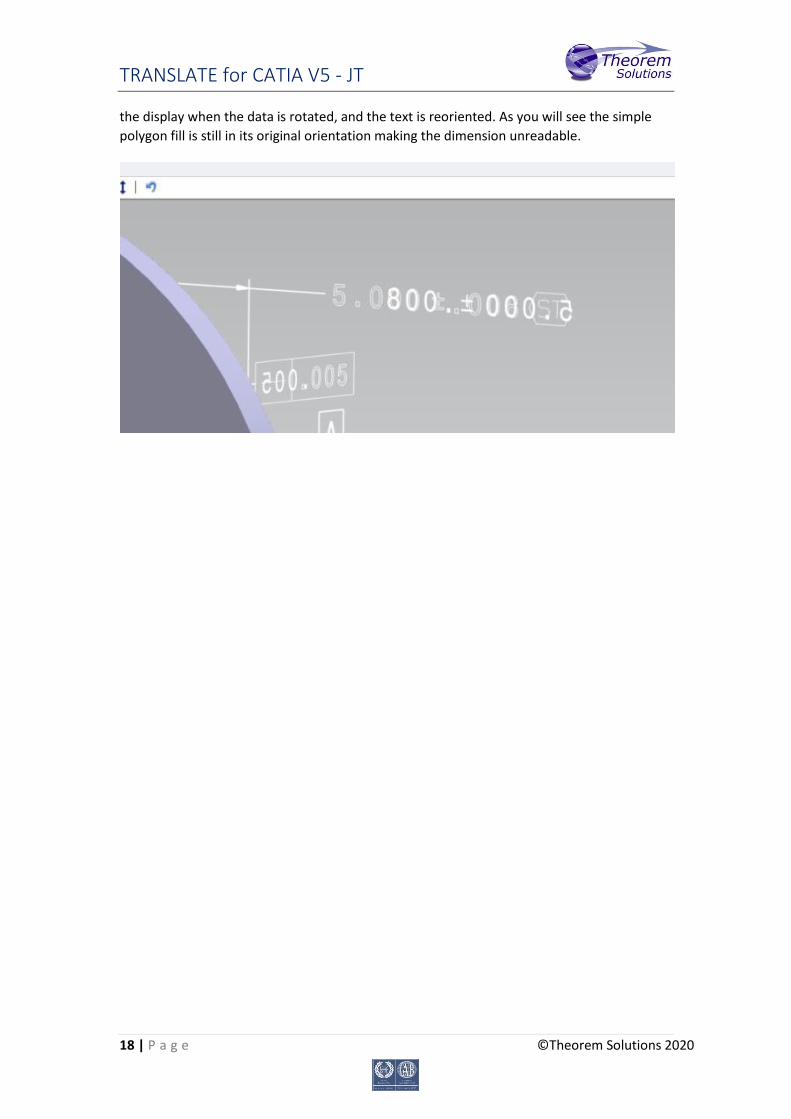
TRANSLATE for CATIA V5 - JT
18 | P a g e ©Theorem Solutions 2020
the display when the data is rotated, and the text is reoriented. As you will see the simple
polygon fill is still in its original orientation making the dimension unreadable.
TRANSLATE for CATIA V5 - JT
19 | P a g e ©Theorem Solutions 2020
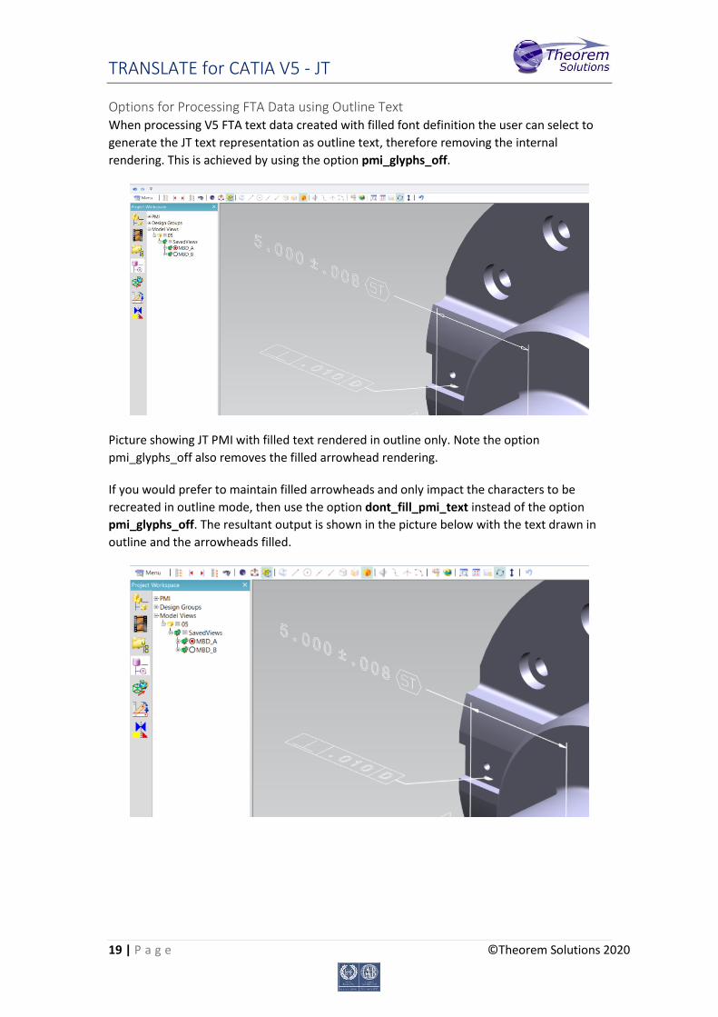
Options for Processing FTA Data using Outline Text When processing V5 FTA text data created with filled font definition the user can select to
generate the JT text representation as outline text, therefore removing the internal
rendering. This is achieved by using the option pmi_glyphs_off.
Picture showing JT PMI with filled text rendered in outline only. Note the option
pmi_glyphs_off also removes the filled arrowhead rendering.
If you would prefer to maintain filled arrowheads and only impact the characters to be
recreated in outline mode, then use the option dont_fill_pmi_text instead of the option
pmi_glyphs_off. The resultant output is shown in the picture below with the text drawn in
outline and the arrowheads filled.
TRANSLATE for CATIA V5 - JT
20 | P a g e ©Theorem Solutions 2020
Common Options for JT to CATIA V5 Within the Configuration Manager pane of the Unified Interface, arguments that can be
specified when publishing JT data into CATIA V5 are grouped into 4 areas:
JT Read – Those arguments that affect how data is read from JT
CATIA V5 Write – Those arguments that affect how the data is written to JT
General – Those arguments that are common to ALL Publishing activities
regardless of source data
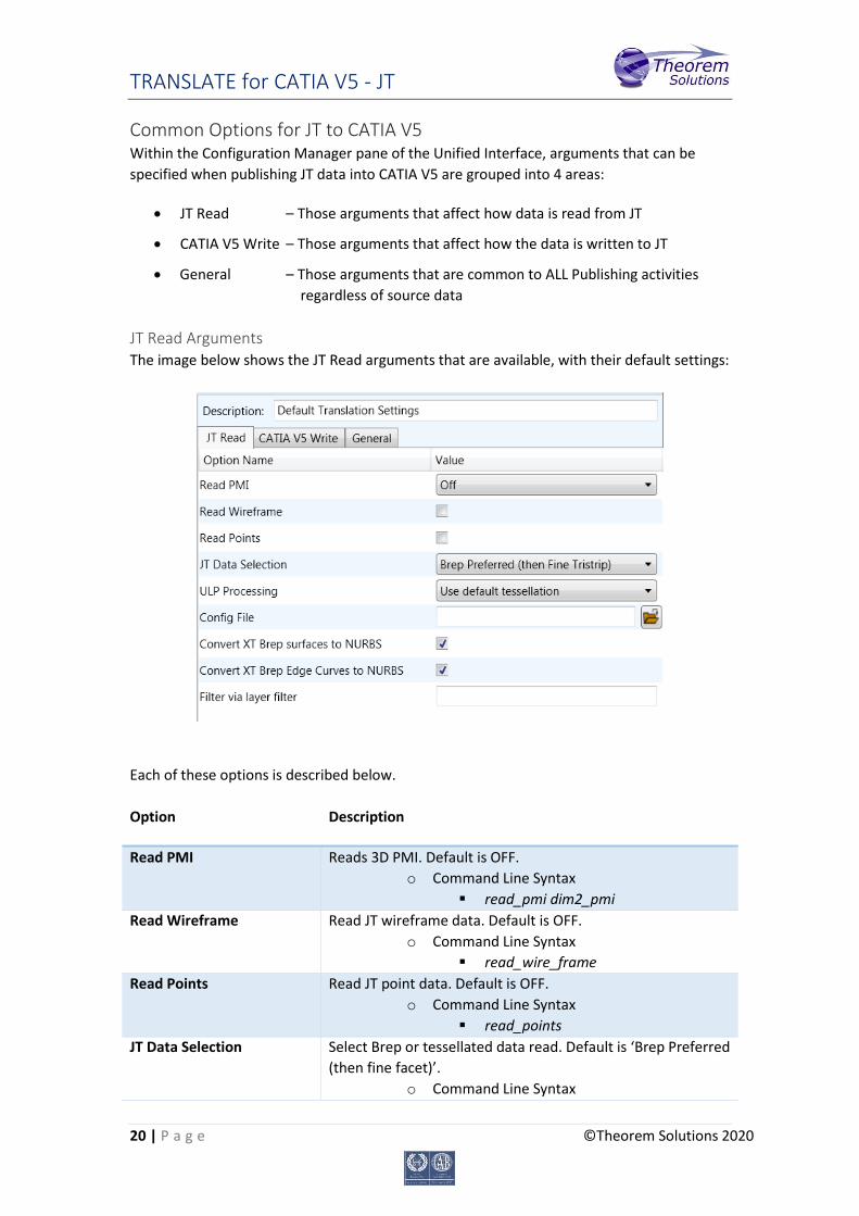
JT Read Arguments The image below shows the JT Read arguments that are available, with their default settings:
Each of these options is described below.
Option Description
Read PMI Reads 3D PMI. Default is OFF.
o Command Line Syntax
read_pmi dim2_pmi
Read Wireframe Read JT wireframe data. Default is OFF.
o Command Line Syntax
read_wire_frame
Read Points Read JT point data. Default is OFF.
o Command Line Syntax
read_points
JT Data Selection Select Brep or tessellated data read. Default is ‘Brep Preferred
(then fine facet)’.
o Command Line Syntax
TRANSLATE for CATIA V5 - JT
21 | P a g e ©Theorem Solutions 2020
Brep Preferred (then Fine Facet):
brep_pref
Brep preferred (then Fine Tristrip):
brep_pref_tri
Brep Only: brep_only
Fine Tristrip: fine_tristrips
Coarse Tristrip: coarse_tristrips
Fine Facet: fine_facets
Coarse Facet: coarse_facets
ULP Processing How to process ULP data in the JT part. Default is ‘Use Default
Tessellation’.
o Command Line Syntax
Use Default Tessellation: Default
Tessellate ULP: tess_ulp
Config File Config File for Brep or ULP tessellation.
o Command Line Syntax
-z [path to file]
Convert XT Brep surfaces to
NURBS
Read XT Brep surfaces as NURBS surfaces (else read in native
form). Default is ON.
o Command Line Syntax
noprep – to turn off
Convert XT Brep Edge
Curves to NURBS
Read XT Brep edge curves as NURBS curves (else read in
native form. Default is ON.
o Command Line Syntax
rd_native_edge – to turn off
Filter via layer filter Supply layer filter(s) separated by commas and double
quoted. Default is OFF.
o Command Line Syntax
layer_filter
TRANSLATE for CATIA V5 - JT
22 | P a g e ©Theorem Solutions 2020
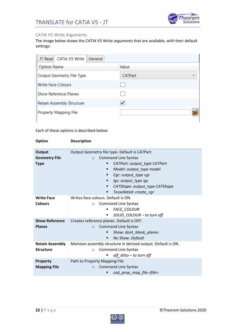
CATIA V5 Write Arguments The image below shows the CATIA V5 Write arguments that are available, with their default settings:
Each of these options is described below:
Option Description
Output
Geometry File
Type
Output Geometry file type. Default is CATPart.
o Command Line Syntax
CATPart: output_type CATPart
Model: output_type model
Cgr: output_type cgr
Igs: output_type igs
CATShape: output_type CATShape
Tessellated: create_cgr
Write Face
Colours
Writes face colours. Default is ON.
o Command Line Syntax
FACE_COLOUR
SOLID_COLOUR – to turn off
Show Reference
Planes
Creates reference planes. Default is OFF.
o Command Line Syntax
Show: dont_blank_planes
No Show: Default
Retain Assembly
Structure
Maintain assembly structure in derived output. Default is ON.
o Command Line Syntax
off_ditto – to turn off
Property
Mapping File
Path to Property Mapping File
o Command Line Syntax
cad_prop_map_file <file>

TRANSLATE for CATIA V5 - JT
23 | P a g e ©Theorem Solutions 2020
JT to CATIA V5 General Arguments
The image below shows the General arguments that are available, with their default
settings:
The option is described below:
Option Description
Advanced Allows any of the Command Line Advanced arguments
documented below to be passed to the Unified Interface
invocation
TRANSLATE for CATIA V5 - JT
24 | P a g e ©Theorem Solutions 2020
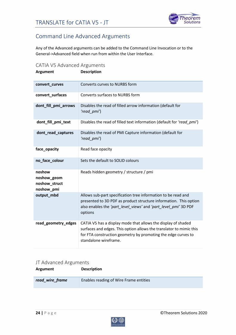
Command Line Advanced Arguments
Any of the Advanced arguments can be added to the Command Line Invocation or to the
General->Advanced field when run from within the User Interface.
CATIA V5 Advanced Arguments Argument Description
convert_curves Converts curves to NURBS form
convert_surfaces Converts surfaces to NURBS form
dont_fill_pmi_arrows Disables the read of filled arrow information (default for
‘read_pmi’)
dont_fill_pmi_text Disables the read of filled text information (default for ‘read_pmi’)
dont_read_captures Disables the read of PMI Capture information (default for
‘read_pmi’)
face_opacity Read face opacity
no_face_colour Sets the default to SOLID colours
noshow
noshow_geom
noshow_struct
noshow_pmi
Reads hidden geometry / structure / pmi
output_mbd Allows sub-part specification tree information to be read and
presented to 3D PDF as product structure information. This option
also enables the ‘part_level_views’ and ‘part_level_pmi’ 3D PDF
options
read_geometry_edges CATIA V5 has a display mode that allows the display of shaded
surfaces and edges. This option allows the translator to mimic this
for FTA construction geometry by promoting the edge curves to
standalone wireframe.
JT Advanced Arguments Argument Description
read_wire_frame Enables reading of Wire Frame entities

TRANSLATE for CATIA V5 - JT
25 | P a g e ©Theorem Solutions 2020
CATIA V5 – JT PDF Add On Products
As an optional feature, the creation of 3D PDF documents can be added to the functionality
of the CATIA V5 – JT license.
This requires an additional software download and is documented within that download.
Please contact [email protected] for more information.
Translating Interactively from within CATIA V5
The CATIA V5 to JT translator allows an active CATIA V5 Part or Assembly to be translated
directly into JT or a JT Part or assembly to be imported, directly from the CATIA V5
application.
In order to translate from within CATIA V5, the CATIA V5 application must be started from
within a Theorem environment, so that the appropriate CATIA V5 menus are loaded.
CATIA V5 can be started from a shortcut, if requested at installation time. Alternatively, it
can be started via the script provided in the Translator installation at:
<installation_directory>\bin\catia5r[version]_start.cmd
(where [version] should be substituted for the version of CATIA V5 that you have installed –
e.g. 26, 28):
TRANSLATE for CATIA V5 - JT
26 | P a g e ©Theorem Solutions 2020
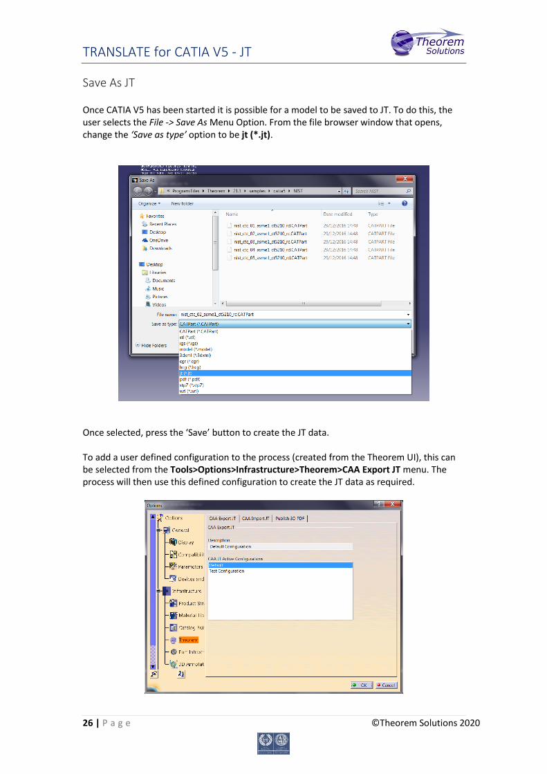
Save As JT Once CATIA V5 has been started it is possible for a model to be saved to JT. To do this, the user selects the File -> Save As Menu Option. From the file browser window that opens, change the ‘Save as type’ option to be jt (*.jt).
Once selected, press the ‘Save’ button to create the JT data.
To add a user defined configuration to the process (created from the Theorem UI), this can be selected from the Tools>Options>Infrastructure>Theorem>CAA Export JT menu. The process will then use this defined configuration to create the JT data as required.
TRANSLATE for CATIA V5 - JT
27 | P a g e ©Theorem Solutions 2020
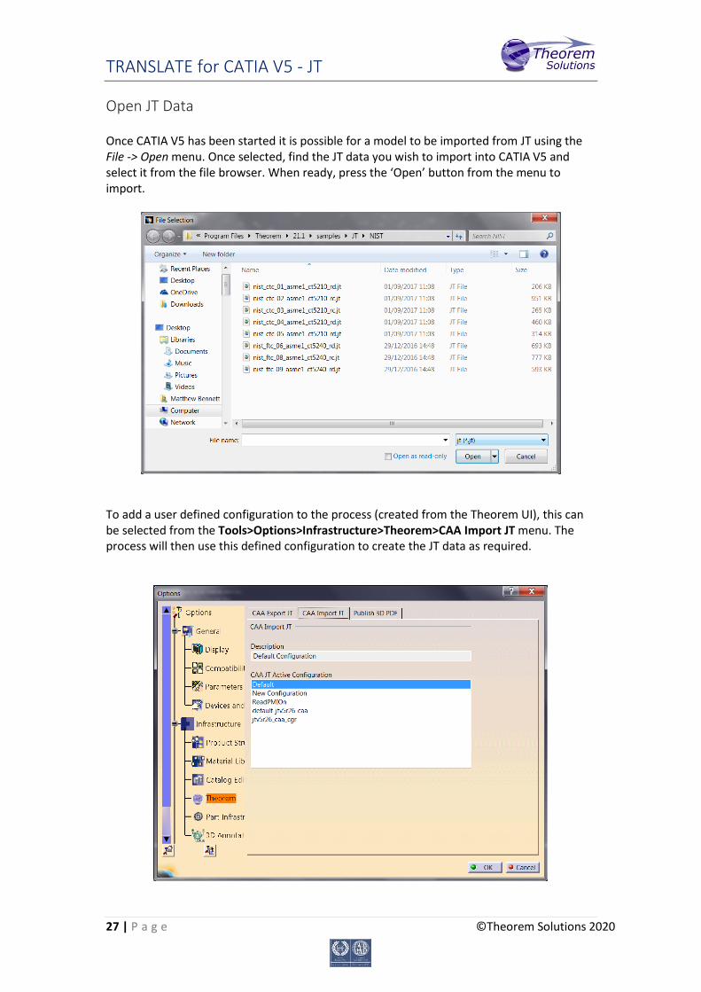
Open JT Data Once CATIA V5 has been started it is possible for a model to be imported from JT using the File -> Open menu. Once selected, find the JT data you wish to import into CATIA V5 and select it from the file browser. When ready, press the ‘Open’ button from the menu to import.
To add a user defined configuration to the process (created from the Theorem UI), this can be selected from the Tools>Options>Infrastructure>Theorem>CAA Import JT menu. The process will then use this defined configuration to create the JT data as required.

TRANSLATE for CATIA V5 - JT
28 | P a g e ©Theorem Solutions 2020
Appendix A – CATIA V5 Configuration
Introduction This Appendix details how to define and configure the CATIA V5 and Theorem environment
to work together.
Conventions Release of CATIA V5
To indicate a release of CATIA V5 the notation <XX> shall be used. This needs to be replaced
with the specific release to be used i.e. 19, 20, 21, 22, 23 24, 25 or 26.
Platform specific directory
Within the installation directory of CATIA V5 there is a platform specific directory i.e.
win_b64. This directory shall be referred to as <OSDS> in this Appendix.
Theorem Installation directory
The Theorem translator installation directory is set at installation time in the translator
ts_env.bat file. This directory shall be noted as <%TS_INST%> in this Appendix.
CATIA V5 Installation Directory Upon installation of a CATIA V5 product the user will be asked to specify the installation
directory. This is the directory which contains the platform specific <OSDS> directory.
Having selected the CATIA V5 installation directory via the browse button, the installation
process will record the location of the CATIA V5 installation directory in the ts_env.bat file.
This file is located in the Theorem translator installation directory. If the location of CATIA V5
subsequently changes, the translator can be guided to the changed location by modifying
this file using a text editor to modify the ts_env.bat that is located in the translator
installation directory.
If no entry is included for DSLICENSING a warning dialog will be displayed which warns of the
empty field. Selecting Yes to continue will allow the installation to continue.
TRANSLATE for CATIA V5 - JT
29 | P a g e ©Theorem Solutions 2020
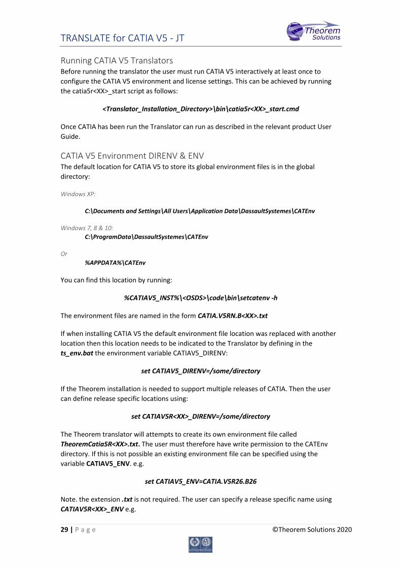
Running CATIA V5 Translators Before running the translator the user must run CATIA V5 interactively at least once to
configure the CATIA V5 environment and license settings. This can be achieved by running
the catia5r<XX>_start script as follows:
<Translator_Installation_Directory>\bin\catia5r<XX>_start.cmd
Once CATIA has been run the Translator can run as described in the relevant product User
Guide.
CATIA V5 Environment DIRENV & ENV The default location for CATIA V5 to store its global environment files is in the global
directory:
Windows XP:
C:\Documents and Settings\All Users\Application Data\DassaultSystemes\CATEnv
Windows 7, 8 & 10:
C:\ProgramData\DassaultSystemes\CATEnv
Or
%APPDATA%\CATEnv
You can find this location by running:
%CATIAV5_INST%\<OSDS>\code\bin\setcatenv -h
The environment files are named in the form CATIA.V5RN.B<XX>.txt
If when installing CATIA V5 the default environment file location was replaced with another
location then this location needs to be indicated to the Translator by defining in the
ts_env.bat the environment variable CATIAV5_DIRENV:
set CATIAV5_DIRENV=/some/directory
If the Theorem installation is needed to support multiple releases of CATIA. Then the user
can define release specific locations using:
set CATIAV5R<XX>_DIRENV=/some/directory
The Theorem translator will attempts to create its own environment file called
TheoremCatia5R<XX>.txt. The user must therefore have write permission to the CATEnv
directory. If this is not possible an existing environment file can be specified using the
variable CATIAV5_ENV. e.g.
set CATIAV5_ENV=CATIA.V5R26.B26
Note. the extension .txt is not required. The user can specify a release specific name using
CATIAV5R<XX>_ENV e.g.
TRANSLATE for CATIA V5 - JT
30 | P a g e ©Theorem Solutions 2020
set CATIAV5R26_ENV=CATIA.V5R26.B26
Checking the CATIA V5 Environment A script is provided to check that the CATIA V5 environment is set up correctly. In a
command window run the command script:
%TS_INST%\bin\checkcatia5r<XX>env.cmd
Checking the Theorem Shared Library A script is provided to ensure that the CATIA V5 environment is compatible with the
Theorem shared library. In a command window run the command script:
%TS_INST%\bin\checkcatia5r<XX>cadverter.cmd
A successful output is an indication that the location for CATIA V5 has been specified to the
Theorem translator correctly and that the correct version of the Theorem CATIA V5
translator products have been installed.
TRANSLATE for CATIA V5 - JT
31 | P a g e ©Theorem Solutions 2020
Appendix B – JT Configuration File
Introduction A configuration file contains the settings for your translations. The configuration file can be
specified using the command line option –config or -z.
If this is not supplied the following directories will be searched in the specified order for the
named configuration files: (TS_INST = Installed directory)
tess.config in the directory where the translator is run
tess.config in TS_INST\etc directory
Two example config files are provided in the TS_INST\etc directory, a
standard tess.config one, and one that illustrates the options required for large assembly
processing,tessLargeAssmCATIA5.config which is documented by some comments within it.
The JT configuration file contains various sections, each containing different settings based
on the section.
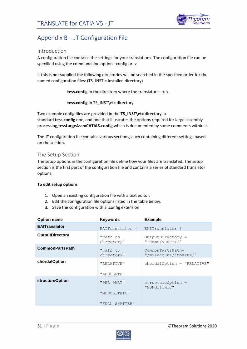
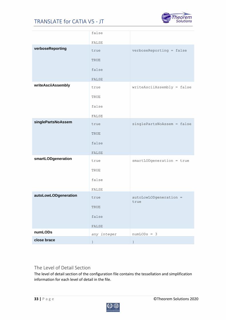
The Setup Section The setup options in the configuration file define how your files are translated. The setup
section is the first part of the configuration file and contains a series of standard translator
options.
To edit setup options
1. Open an existing configuration file with a text editor.
2. Edit the configuration file options listed in the table below.
3. Save the configuration with a .config extension
Option name Keywords Example
EAITranslator
EAITranslator { EAITranslator {
OutputDirectory
"path to
directory"
OutputDirectory =
"/home/<user>/"
CommonPartsPath
"path to
directory"
CommonPartsPath=
"/myaccount/jtparts/"
chordalOption
"RELATIVE"
"ABSOLUTE"
chordalOption = "RELATIVE"
structureOption
"PER_PART"
"MONOLITHIC"
"FULL_SHATTER"
structureOption =
"MONOLITHIC"
TRANSLATE for CATIA V5 - JT
32 | P a g e ©Theorem Solutions 2020
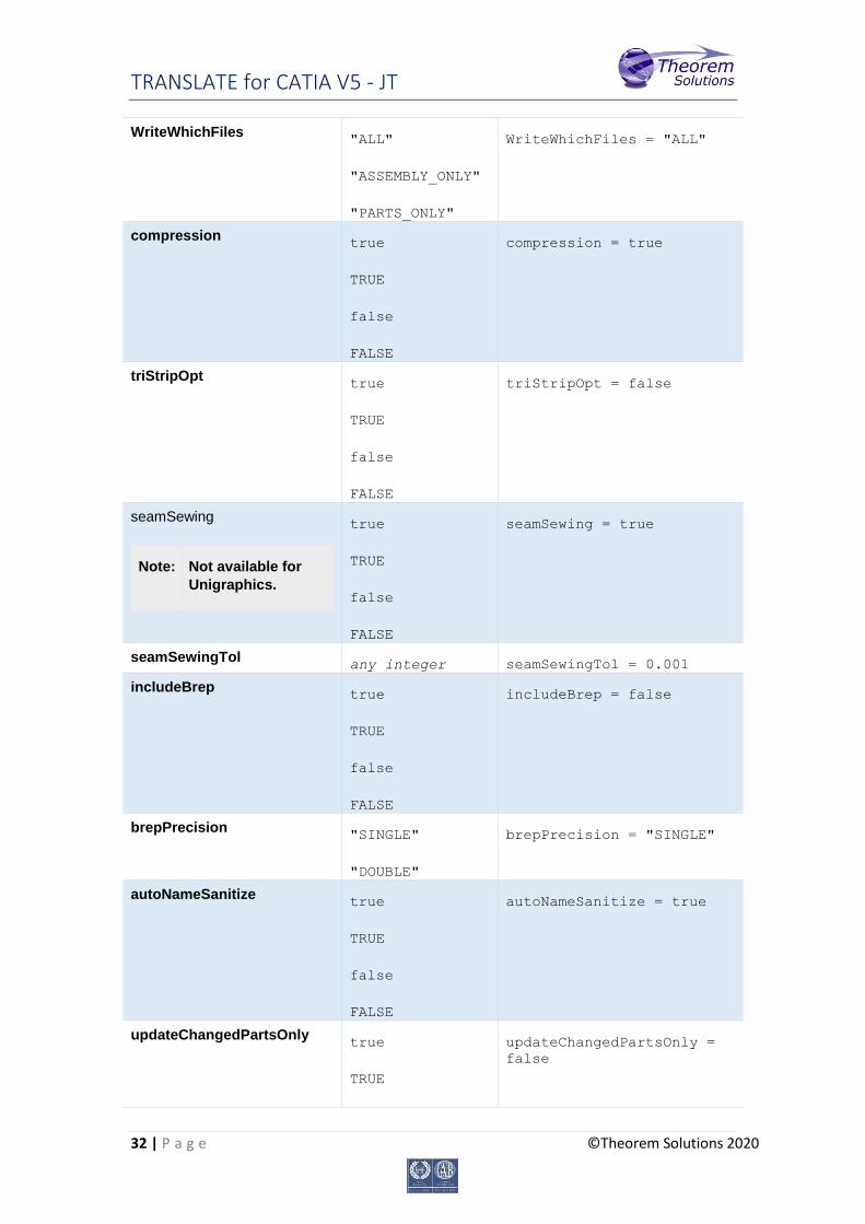
WriteWhichFiles
"ALL"
"ASSEMBLY_ONLY"
"PARTS_ONLY"
WriteWhichFiles = "ALL"
compression
true
TRUE
false
FALSE
compression = true
triStripOpt
true
TRUE
false
FALSE
triStripOpt = false
seamSewing
Note: Not available for
Unigraphics.
true
TRUE
false
FALSE
seamSewing = true
seamSewingTol
any integer seamSewingTol = 0.001
includeBrep
true
TRUE
false
FALSE
includeBrep = false
brepPrecision
"SINGLE"
"DOUBLE"
brepPrecision = "SINGLE"
autoNameSanitize
true
TRUE
false
FALSE
autoNameSanitize = true
updateChangedPartsOnly
true
TRUE
updateChangedPartsOnly =
false
TRANSLATE for CATIA V5 - JT
33 | P a g e ©Theorem Solutions 2020
false
FALSE
verboseReporting
true
TRUE
false
FALSE
verboseReporting = false
writeAsciiAssembly
true
TRUE
false
FALSE
writeAsciiAssembly = false
singlePartsNoAssem
true
TRUE
false
FALSE
singlePartsNoAssem = false
smartLODgeneration
true
TRUE
false
FALSE
smartLODgeneration = true
autoLowLODgeneration
true
TRUE
false
FALSE
autoLowLODgeneration =
true
numLODs
any integer numLODs = 3
close brace
} }
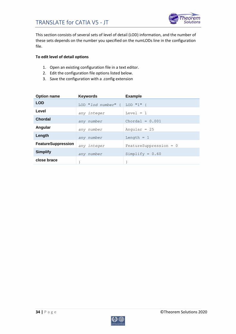
The Level of Detail Section The level of detail section of the configuration file contains the tessellation and simplification
information for each level of detail in the file.
TRANSLATE for CATIA V5 - JT
34 | P a g e ©Theorem Solutions 2020
This section consists of several sets of level of detail (LOD) information, and the number of
these sets depends on the number you specified on the numLODs line in the configuration
file.
To edit level of detail options
1. Open an existing configuration file in a text editor.
2. Edit the configuration file options listed below.
3. Save the configuration with a .config extension
Option name Keywords Example
LOD
LOD "lod number" { LOD "1" {
Level
any integer Level = 1
Chordal
any number Chordal = 0.001
Angular
any number Angular = 25
Length
any number Length = 1
FeatureSuppression
any integer FeatureSuppression = 0
Simplify
any number Simplify = 0.60
close brace
} }

TRANSLATE for CATIA V5 - JT
35 | P a g e ©Theorem Solutions 2020
The Filter Section The filter section of the configuration file contains the filename and metadata filtering
information. Edit this section if you want to change how the translator sanitizes filenames
and filters metadata keys.
To edit filter options
1. Open an existing configuration file with a text editor.
2. Edit the configuration file options from the table below.
3. Save the configuration with a .config extension
Option name Keywords Example
Filter
Filter { Filter {
FilenameSanitizeSet
"string of
characters"
FilenameSanitizeSet =
"abc123."
FilenameSanitizeSetAdd
"string of
characters"
FilenameSanitizeSetAdd = "4l"
FilenameSanitizeSetDelete
"string of
characters"
FilenameSanitizeSetDelete =
"c"
MetadataKey
"string of
characters"
MetadataKey = "metadata key
to exclude"
close brace
} }

TRANSLATE for CATIA V5 - JT
36 | P a g e ©Theorem Solutions 2020
The Metadata section The metadata section sets which metadata to attach to all parts, assemblies and nodes of
the model.
Note: Be sure to add these options to the configuration file in pairs: one line to define the metadata
key and one line to define the metadata value.
To edit metadata options
1. Open an existing configuration file (.CONFIG) in a text editor.
2. Edit the configuration file options shown in the table below.
3. Save the configuration with a .config extension
Option name Keywords Example
Metadata
Metadata { Metadata {
AddToParts
"string of
characters"
AddToParts = "<metadata key>"
AddToParts = "<metadata value>"
AddToAssemblies
"string of
characters"
AddToAssemblies = "<metadata
key>"
AddToAssemblies = "<metadata
value>"
AddToAllNodes
"string of
characters"
AddToAllNodes = "<metadata
key>"
AddToAllNodes = "<metadata
value>"
close brace
} }

TRANSLATE for CATIA V5 - JT
37 | P a g e ©Theorem Solutions 2020
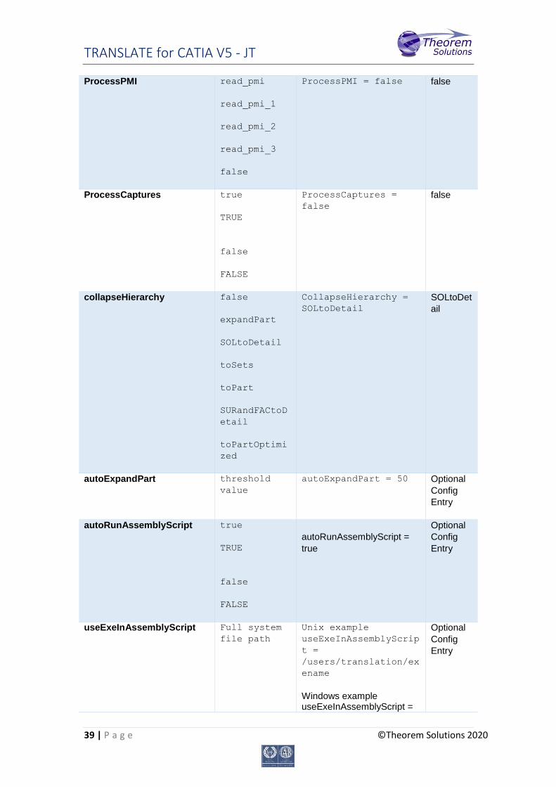
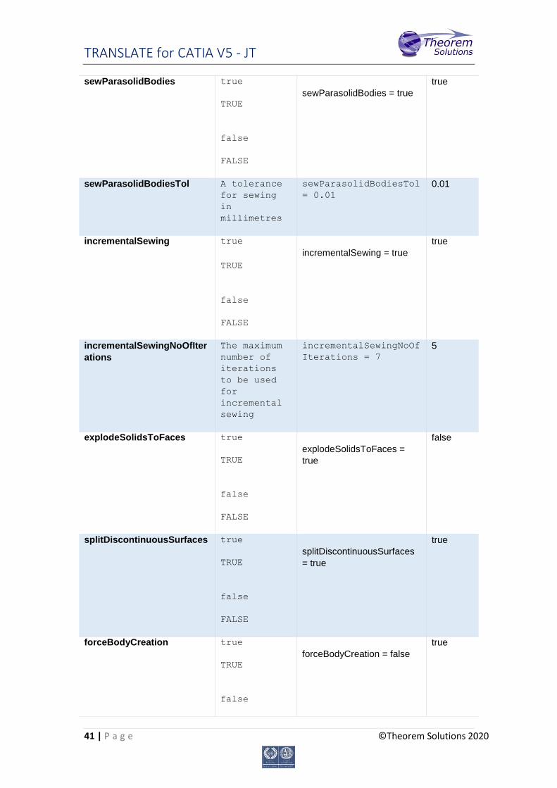
The Special Section The special section of the configuration file contains lines that are unique to this translator.
To edit special options
1. Open an existing configuration file with a text editor.
2. Edit the configuration file options shown in the table below.
3. Save the configuration with a .config file extension.
Option Keyword Example Default
Value
Catia5Options Catia5Option
s {
Catia5Options {
ProcessSolids true
TRUE
false
FALSE
ProcessSolids = true true
ProcessOpenSoilds true
TRUE
false
FALSE
ProcessOpenSolids =
true
true
ProcessWireFrame true
TRUE
false
FALSE
ProcessWireFrame =
false
true
ProcessPoints true
TRUE
false
FALSE
ProcessPoints = true true
ProcessHiddenGeom true
TRUE
false
FALSE
ProcessHiddenGeom =
false
false
ProcessLayers ALL_LAYERS
A comma
ProcessLayers = 1-10,
20, 30-40, 88
ALL_LAY
ERS

TRANSLATE for CATIA V5 - JT
38 | P a g e ©Theorem Solutions 2020
separated
list of
layer
numbers (0-
255), using
and hyphen
'-' to
separate
number
ranges.
ReportFilename
Full system
file path
Unix example
ReportFilename =
/users/caddata/transl
ation/result/part55
Windows example ReportFilename = P:\caddata\translation\result\part55
Unix
system
/tmp/tscpr
ogressyi
Windows system C:%TEMP%\tscprogressyi
OutputUnits
mm
millimetres
cm
centimetres
m
metre
metres
inches
feet
yards
inputUnits
OutputUnits = mm inputUnits
AppendCADExtension
true
TRUE
false
FALSE
AppendCADExtension =
false
false
TRANSLATE for CATIA V5 - JT
39 | P a g e ©Theorem Solutions 2020
ProcessPMI
read_pmi
read_pmi_1
read_pmi_2
read_pmi_3
false
ProcessPMI = false false
ProcessCaptures
true
TRUE
false
FALSE
ProcessCaptures =
false
false
collapseHierarchy
false
expandPart
SOLtoDetail
toSets
toPart
SURandFACtoD
etail
toPartOptimi
zed
CollapseHierarchy =
SOLtoDetail
SOLtoDet
ail
autoExpandPart
threshold
value
autoExpandPart = 50 Optional
Config
Entry
autoRunAssemblyScript
true
TRUE
false
FALSE
autoRunAssemblyScript =
true
Optional
Config
Entry
useExeInAssemblyScript
Full system
file path
Unix example
useExeInAssemblyScrip
t =
/users/translation/ex
ename
Windows example useExeInAssemblyScript =
Optional
Config
Entry

TRANSLATE for CATIA V5 - JT
40 | P a g e ©Theorem Solutions 2020
X:\users\translation\exename.exe
useLogDirInAssemblyScript
Full system
path
Unix example
useLogDirInAssemblySc
ript =
/users/translation/lo
gDir
Windows example useLogDirInAssemblyScript = X:\users\translation\logDir
Optional
Config
Entry
zPart
Full system
file path
Unix example
zPart =
/users/translation/te
ssPart.config
Windows example zPart = X:\users\translation\tessPart.config
Optional
Config
Entry
structureOutputType
JT
PLMXML
PLMXMLJT
structureOutputType =
JT
JT
plmxmlPropertyMappingFile
Mapping File
for PLMXML
Properties
Windows example
plmxmlPropertyMapping
File =
X:\users\translation\
plmxml_property_mappi
ng.txt
Optional
Config
Entry
brepType
JT
XT
XTJT
brepType = XT JT
parasolidTolerantModelling
true
TRUE
false
FALSE
parasolidTolerantModelling
= true
true
parasolidTolerantModelling
Factor
An integer
factor
parasolidTolerantMode
llingFactor = 4
3
TRANSLATE for CATIA V5 - JT
41 | P a g e ©Theorem Solutions 2020
sewParasolidBodies
true
TRUE
false
FALSE
sewParasolidBodies = true
true
sewParasolidBodiesTol
A tolerance
for sewing
in
millimetres
sewParasolidBodiesTol
= 0.01
0.01
incrementalSewing
true
TRUE
false
FALSE
incrementalSewing = true
true
incrementalSewingNoOfIter
ations
The maximum
number of
iterations
to be used
for
incremental
sewing
incrementalSewingNoOf
Iterations = 7
5
explodeSolidsToFaces
true
TRUE
false
FALSE
explodeSolidsToFaces =
true
false
splitDiscontinuousSurfaces
true
TRUE
false
FALSE
splitDiscontinuousSurfaces
= true
true
forceBodyCreation
true
TRUE
false
forceBodyCreation = false
true
TRANSLATE for CATIA V5 - JT
42 | P a g e ©Theorem Solutions 2020
FALSE
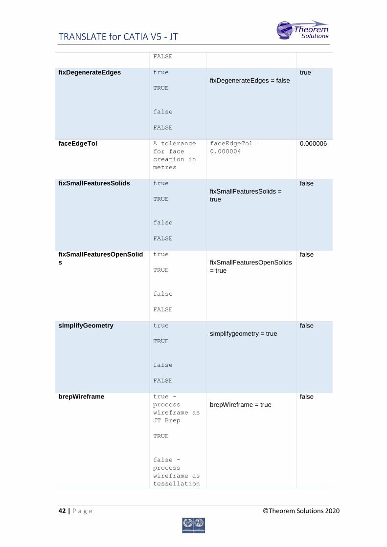
fixDegenerateEdges
true
TRUE
false
FALSE
fixDegenerateEdges = false
true
faceEdgeTol
A tolerance
for face
creation in
metres
faceEdgeTol =
0.000004
0.000006
fixSmallFeaturesSolids
true
TRUE
false
FALSE
fixSmallFeaturesSolids =
true
false
fixSmallFeaturesOpenSolid
s
true
TRUE
false
FALSE
fixSmallFeaturesOpenSolids
= true
false
simplifyGeometry
true
TRUE
false
FALSE
simplifygeometry = true
false
brepWireframe
true -
process
wireframe as
JT Brep
TRUE
false -
process
wireframe as
tessellation
brepWireframe = true
false

TRANSLATE for CATIA V5 - JT
43 | P a g e ©Theorem Solutions 2020
FALSE
produceTessellatedOutput
true
TRUE
false
FALSE
produceTessellatedOutput =
true
false
expandPart
true
TRUE
false
FALSE
expandPart = true
false
reuseSolids
true
TRUE
false
FALSE
reuseSolids = true
false
cadPropertyMappingFile
Mapping File
for JT
Properties
Windows example
cadPropertyMappingFil
e =
X:\users\translation\
cad_property_mapping.
txt
Optional
Config
Entry
addSemanticPMI
true
TRUE
false
FALSE
addSemanticPMI = true
false
JTBrepFixup
true
TRUE
false
JTBrepFixup = false
true
TRANSLATE for CATIA V5 - JT
44 | P a g e ©Theorem Solutions 2020
FALSE
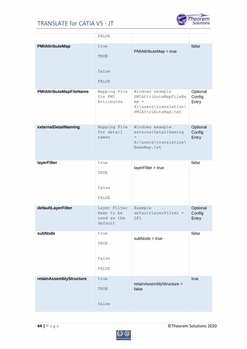
PMIAttributeMap
true
TRUE
false
FALSE
PMIAttributeMap = true
false
PMIAttributeMapFileName
Mapping File
for PMI
Attributes
Windows example
PMIAttributeMapFileNa
me =
X:\users\translation\
PMIAttributeMap.txt
Optional
Config
Entry
externalDetailNaming
Mapping File
for detail
names
Windows example
externalDetailNaming
=
X:\users\translation\
NameMap.txt
Optional
Config
Entry
layerFilter
true
TRUE
false
FALSE
layerFilter = true
false
defaultLayerFilter
Layer Filter
Name to be
used as the
default
Example
defaultLayerFilter =
LF1
Optional
Config
Entry
subNode
true
TRUE
false
FALSE
subNode = true
false
retainAssemblyStructure
true
TRUE
false
retainAssemblyStructure =
false
true
TRANSLATE for CATIA V5 - JT
45 | P a g e ©Theorem Solutions 2020
FALSE
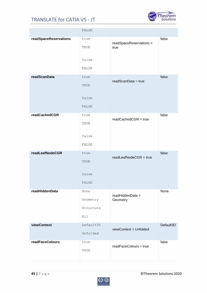
readSpaceReservations
true
TRUE
false
FALSE
readSpaceReservations =
true
false
readScanData
true
TRUE
false
FALSE
readScanData = true
false
readCachedCGR
true
TRUE
false
FALSE
readCachedCGR = true
false
readLeafNodeCGR
true
TRUE
false
FALSE
readLeafNodeCGR = true
false
readHiddenData
None
Geometry
Structure
All
readHiddenData =
Geometry
None
viewContext
Default3D
Unfolded
viewContext = Unfolded
Default3D
readFaceColours
true
TRUE
readFaceColours = true
false
TRANSLATE for CATIA V5 - JT
46 | P a g e ©Theorem Solutions 2020
false
FALSE
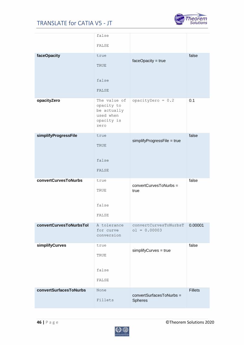
faceOpacity
true
TRUE
false
FALSE
faceOpacity = true
false
opacityZero
The value of
opacity to
be actually
used when
opacity is
zero
opacityZero = 0.2 0.1
simplifyProgressFile
true
TRUE
false
FALSE
simplifyProgressFile = true
false
convertCurvesToNurbs
true
TRUE
false
FALSE
convertCurvesToNurbs =
true
false
convertCurvesToNurbsTol
A tolerance
for curve
conversion
convertCurvesToNurbsT
ol = 0.00003
0.00001
simplifyCurves
true
TRUE
false
FALSE
simplifyCurves = true
false
convertSurfacesToNurbs
None
Fillets
convertSurfacesToNurbs =
Spheres
Fillets
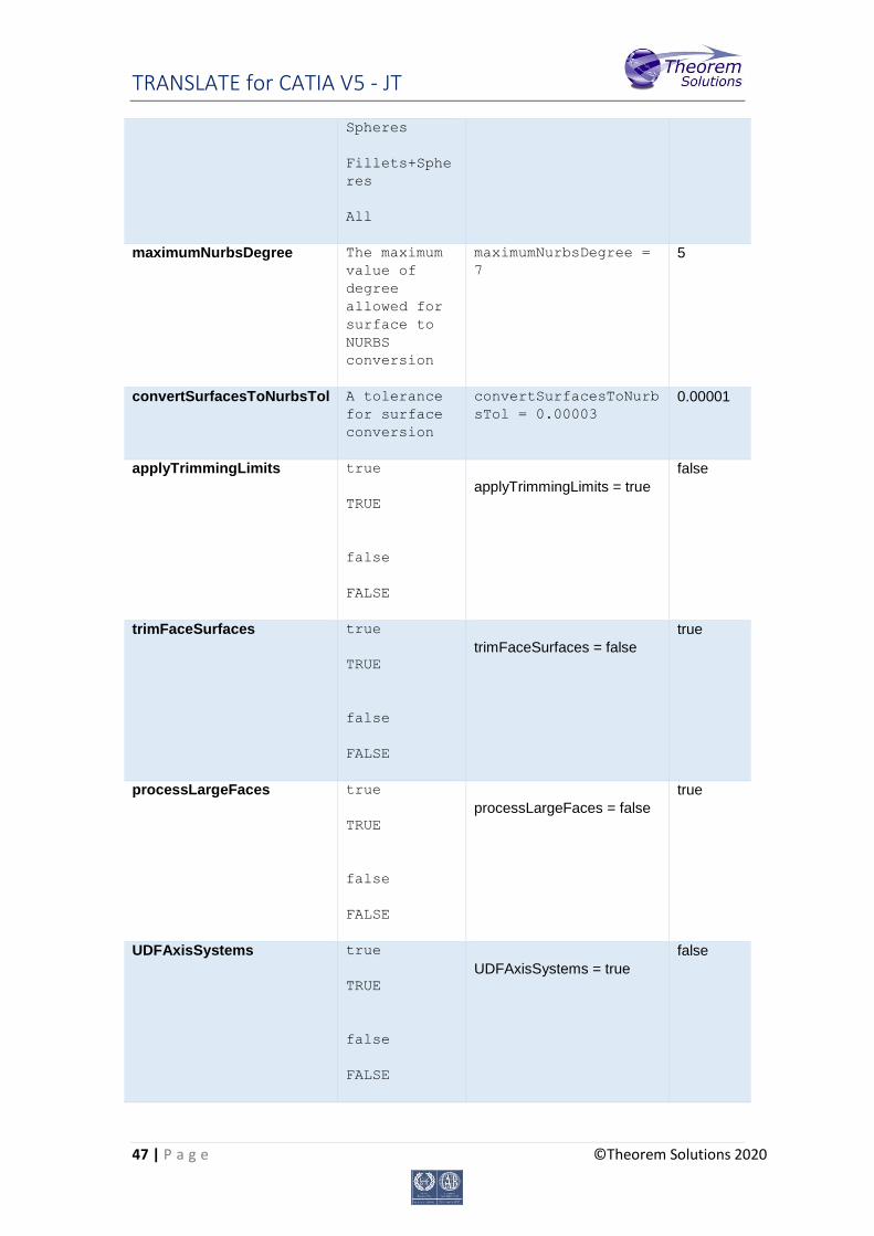
TRANSLATE for CATIA V5 - JT
47 | P a g e ©Theorem Solutions 2020
Spheres
Fillets+Sphe
res
All
maximumNurbsDegree
The maximum
value of
degree
allowed for
surface to
NURBS
conversion
maximumNurbsDegree =
7
5
convertSurfacesToNurbsTol
A tolerance
for surface
conversion
convertSurfacesToNurb
sTol = 0.00003
0.00001
applyTrimmingLimits
true
TRUE
false
FALSE
applyTrimmingLimits = true
false
trimFaceSurfaces
true
TRUE
false
FALSE
trimFaceSurfaces = false
true
processLargeFaces
true
TRUE
false
FALSE
processLargeFaces = false
true
UDFAxisSystems
true
TRUE
false
FALSE
UDFAxisSystems = true
false
TRANSLATE for CATIA V5 - JT
48 | P a g e ©Theorem Solutions 2020
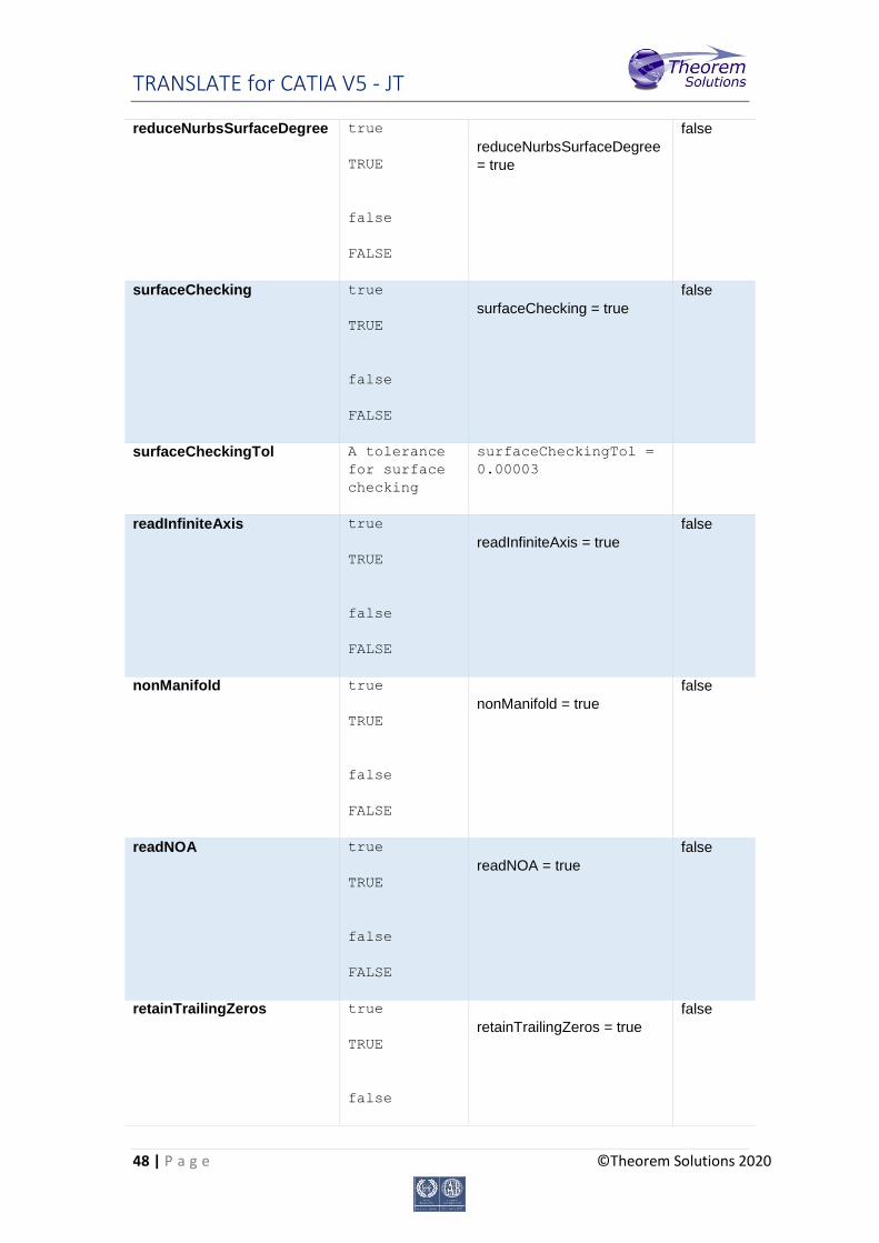
reduceNurbsSurfaceDegree
true
TRUE
false
FALSE
reduceNurbsSurfaceDegree
= true
false
surfaceChecking
true
TRUE
false
FALSE
surfaceChecking = true
false
surfaceCheckingTol
A tolerance
for surface
checking
surfaceCheckingTol =
0.00003
readInfiniteAxis
true
TRUE
false
FALSE
readInfiniteAxis = true
false
nonManifold
true
TRUE
false
FALSE
nonManifold = true
false
readNOA
true
TRUE
false
FALSE
readNOA = true
false
retainTrailingZeros
true
TRUE
false
retainTrailingZeros = true
false
TRANSLATE for CATIA V5 - JT
49 | P a g e ©Theorem Solutions 2020
FALSE
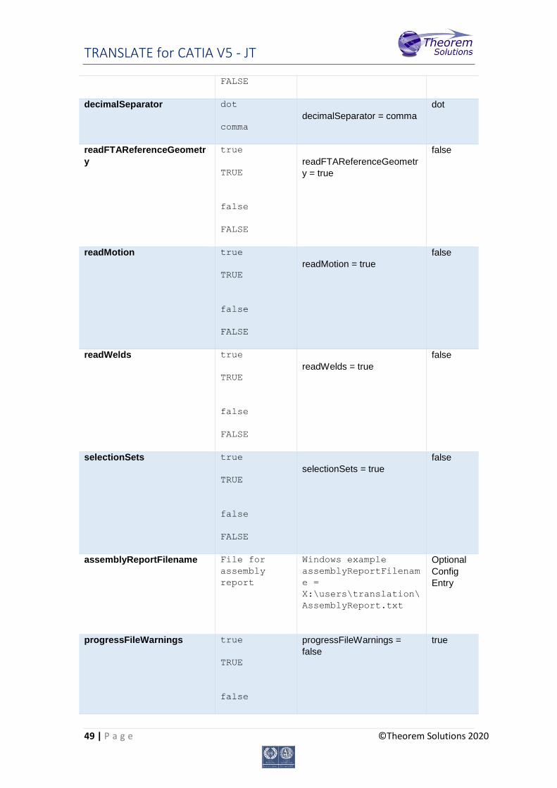
decimalSeparator
dot
comma
decimalSeparator = comma
dot
readFTAReferenceGeometr
y
true
TRUE
false
FALSE
readFTAReferenceGeometr
y = true
false
readMotion
true
TRUE
false
FALSE
readMotion = true
false
readWelds
true
TRUE
false
FALSE
readWelds = true
false
selectionSets
true
TRUE
false
FALSE
selectionSets = true
false
assemblyReportFilename
File for
assembly
report
Windows example
assemblyReportFilenam
e =
X:\users\translation\
AssemblyReport.txt
Optional
Config
Entry
progressFileWarnings
true
TRUE
false
progressFileWarnings =
false
true
TRANSLATE for CATIA V5 - JT
50 | P a g e ©Theorem Solutions 2020
FALSE
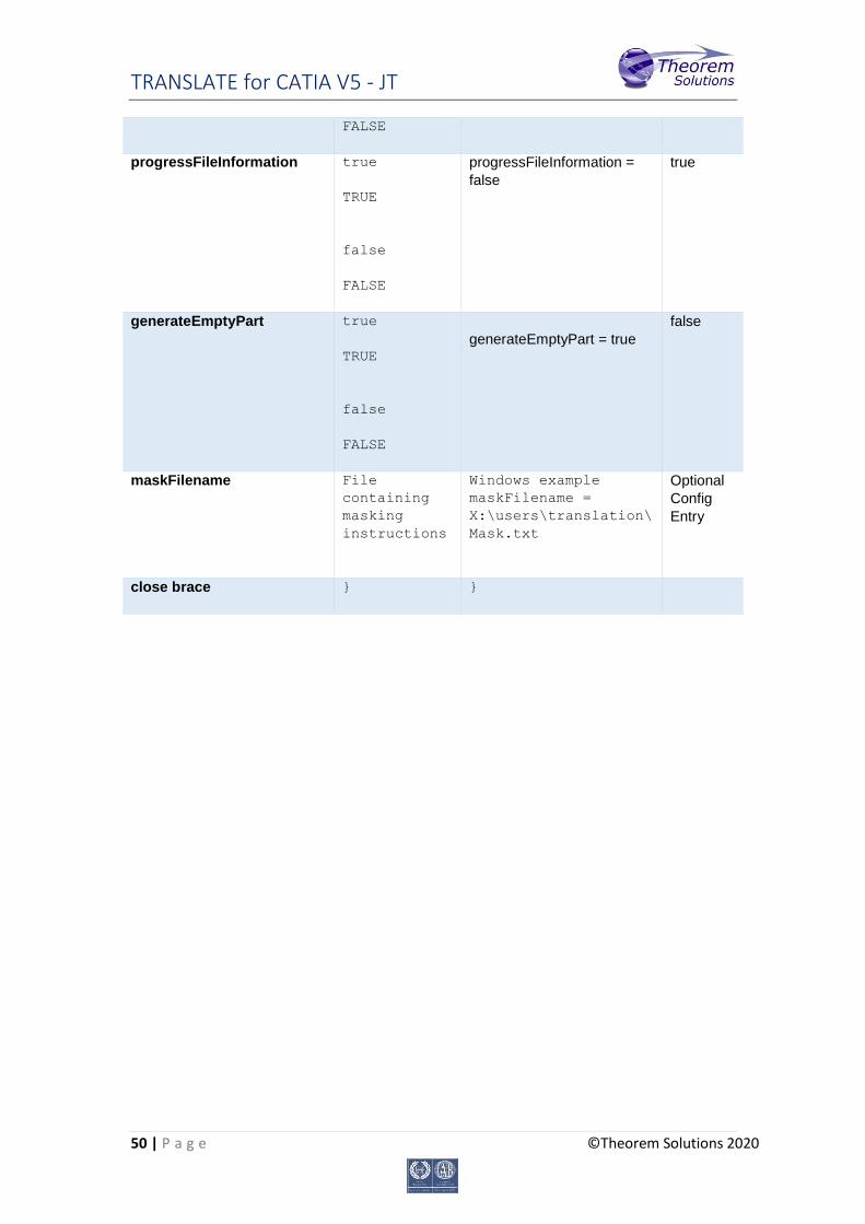
progressFileInformation
true
TRUE
false
FALSE
progressFileInformation =
false
true
generateEmptyPart
true
TRUE
false
FALSE
generateEmptyPart = true
false
maskFilename
File
containing
masking
instructions
Windows example
maskFilename =
X:\users\translation\
Mask.txt
Optional
Config
Entry
close brace
} }


