VITALink Block Splice UL Listed 2 Hour Fire-Rated Splice VITALink® MC Cables, UL FHIT 120
Installation Instructions
Description
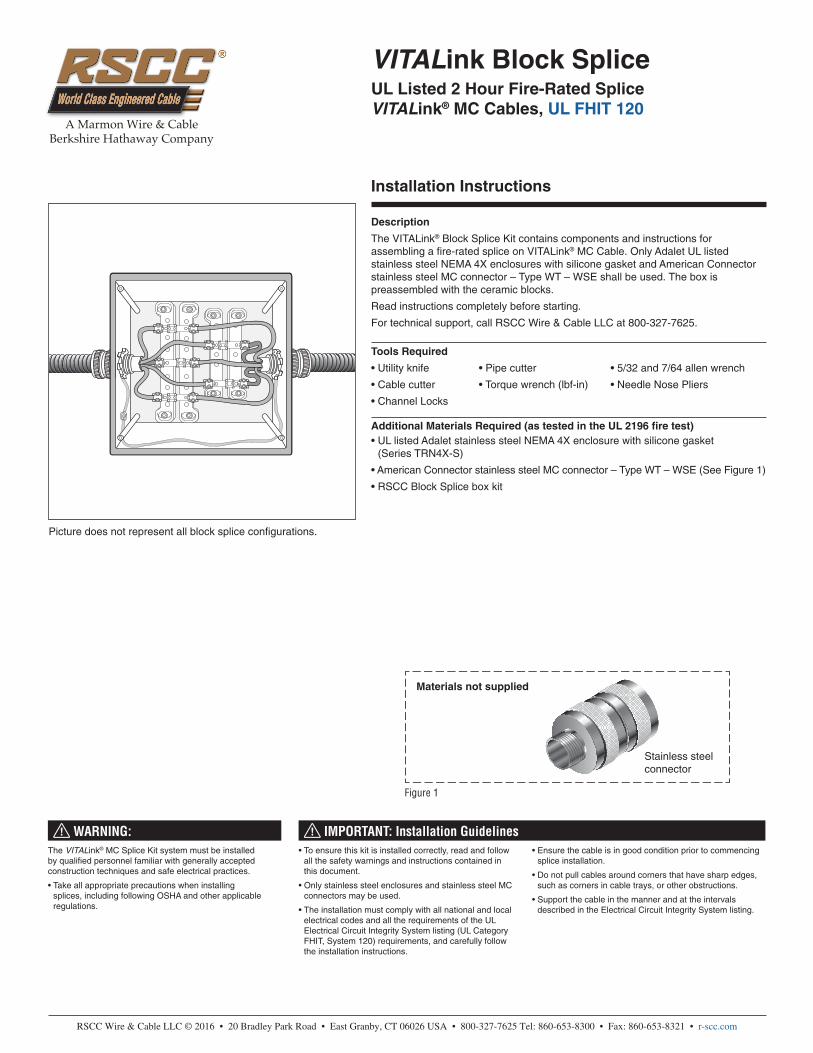
The VITALink® Block Splice Kit contains components and instructions for assembling a fire-rated splice on VITALink® MC Cable. Only Adalet UL listed stainless steel NEMA 4X enclosures with silicone gasket and American Connector stainless steel MC connector – Type WT – WSE shall be used. The box is preassembled with the ceramic blocks.
Read instructions completely before starting.
For technical support, call RSCC Wire & Cable LLC at 800-327-7625.
Tools Required
• Utility knife • Pipe cutter • 5/32 and 7/64 allen wrench
Additional Materials Required (as tested in the UL 2196 fire test)• UL listed Adalet stainless steel NEMA 4X enclosure with silicone gasket
(Series TRN4X-S)
• American Connector stainless steel MC connector – Type WT – WSE (See Figure 1)
• RSCC Block Splice box kit
Materials not supplied
Stainless steel connector
WARNING: IMPORTANT: Installation GuidelinesThe VITALink® MC Splice Kit system must be installed by qualified personnel familiar with generally accepted construction techniques and safe electrical practices.
• Take all appropriate precautions when installing splices, including following OSHA and other applicable regulations.
• To ensure this kit is installed correctly, read and follow all the safety warnings and instructions contained in this document.
• Only stainless steel enclosures and stainless steel MC connectors may be used.
• The installation must comply with all national and local electrical codes and all the requirements of the UL Electrical Circuit Integrity System listing (UL Category FHIT, System 120) requirements, and carefully follow the installation instructions.
• Ensure the cable is in good condition prior to commencing splice installation.
• Do not pull cables around corners that have sharp edges, such as corners in cable trays, or other obstructions.
• Support the cable in the manner and at the intervals described in the Electrical Circuit Integrity System listing.
Figure 1
Picture does not represent all block splice configurations.
VITALink® MC 2 Hour Block Splice Kit Installation Instructions
2
Patent No.7,339,115 B2
GeneralOnly use Adalet stainless steel NEMA 4X enclosure with silicone gasket. Support the cable within 12 inches from box and every four feet on center thereafter. RSCC’s Firewall® LSZH bonding wire may be used inside the box. Do not introduce any materials into splice box that are not described within this installation guide. Taps in any orientation may be connected to the bus bars (not shown).
MC Connector Installation
1 2The MC Connector must be American Connector WT-WSC series stainless steel• Check to ensure you have all connector components
• Remove enough armor so the conductors can be easily spliced inside the enclosure. To avoid damaging the insulation on the conductors it is advisable to leave the white inner jacket until you insert the cable into the enclosure.
• Strip the black outer jacket to the length specified in the connector instructions.
• Inspect the edge of the armor for any burrs or sharp edges. Flatten or remove as necessary with needle nose pliers.
• Slide connector nut and gasket over cable sheath jacket.
Note: for detailed instructions on preparation of cable, including removal of armor, see the VITALink Installation Manual.
3 4• Screw connector onto sheath and continue until tight. • Tighten the connector nut onto the connector.
VITALink® MC 2 Hour Block Splice Kit Installation Instructions
3
Patent No.7,339,115 B2
Phase Neutral & Ground
See next page for Step 4.
Block Splice Installation
1 Secure Cable and Grounds 2 Remove Inner JacketRead Section completely before beginning installation
• Prepare box cutouts and file sharp edges as needed. Clean up any metal shavings or oil. Some boxes come pre-cut.
• Ensure rubber gasket is on connector and insert cables into enclosure taking care not to nick or cut the cable core.
• Attach and secure the MC connector to the steel box using locknut.
• Attach the earth tag and secure second locknut to the MC connector.
• Attach bare ground or RSCC Firewall® LSZH green ground to the earth tag, ground copper bar, and ground stud to bond the connector, cable, and box to ground. Train the ground/bond wires toward the bottom of the box as shown in the illustration. Train the ground wire from the ground copper bar to the back of the SS box.
• Taking care not to nick or cut the black insulation, carefully remove the white inner jacket leaving a minimum of ½ inch where the cable exits the threaded part of the MC connector. One method to accomplish this is to cut through the end of the inner jacket ½ inch inward and use your hands to peel the jacket back. This is preferred over scoring the jacket lengthwise down the cable because it eliminates the risk of cutting the insulation accidentally. Damage to the insulation will require a new piece of cable.
3 Splice Layout and Termination
Note 1:
Small bus bar (Approx. 2-3/4" long): 14 AWG –8 AWG
Large bus bar (Approx. 4-3/8" long): 6 AWG – 2 AWG
Large bus bar (Between plates with copper plate on bottom): one 14 AWG – 10 AWG or two 12 AWG
• Cut the ends of the cable square and carefully remove the black insulation. Strip 9/16" for small bus bar, 7/8" for large bus bar.
• Train the conductors not to exceed the minimum bend radii.
• For boxes with different size ceramic blocks, only use the copper bus bars on the large ceramic blocks for phase conductors.
• Insert stripped conductor under or between plates per Note 1. Termination of conductor on bus bar can be used at any plate location based on field conditions while respecting minimum bend radius requirements. Conductor should extend slightly past compression plates when inserted into termination. See note below for bus bar conductor size ranges.
• Train conductors to minimize crisscrossing and not exceeding minimum bend radius. Space conductors to maximize space between phase to phase and phase to ground. Phase Conductors should not touch box.
• Using a torque wrench, tighten the copper bars Allen screws to the following torque.
Large bus bar = 31.2 in-lbf Min – 36 in-lbf Max
Small bus bar = 13.2 in-lbf Min – 18 in-lbf Max
• Inspect insulation to verify it was not damaged or cut during installation.
VITALink® MC 2 Hour Block Splice Kit Installation Instructions
4
Patent No.7,339,115 B2
RSCC Wire & Cable LLC. 20 Bradley Park Road East Granby, CT 06026 USA Tel: 860-653-8300 Fax: 860-653-8301 r-scc.com
11-1-16
4 Clean Up, Final Inspection, Close Box• Remove any loose debris from inside the box.
• Attach stainless steel cover plate on top of standoffs as shown below. Tighten all four screws securely.
• Inspect box cover gasket for any damage and wipe clean if it is dirty.
• Secure the box cover and gasket to the box using the clips and tighten screws (not shown).
Table 1 – Box SizesConductor
SizeConductor Number
Box Size WxHxD (In)
Maximum distance between
connectors (In)
14 AWG
2
12x10x5 12
34567891012
12 AWG – 10 AWG
2
12x10x5 or 14x16x4
16
34567891012
8 AWG
2
12x10x5 or 14x16x4
345678
6 AWG
2
14x16x4
34567
4 AWG
3
14x16x4456
3 AWG – 2 AWG3
14x16x445
Minimum Box Depth of 4 inches. Box depths shown are standard designs. Splices can be arrayed in boxes with dimensions modified in the height direction in Multiples of the Box Height Dimension (ex. 12x10x5, 12x20x5, 12x30x5, etc). Width and height dimensions become height and width dimensions when the box is rotated 90 degrees.