VJK^U rerunning rage i ui 1 District I 1625 N. French Dr., Hobbs, NM 88240 Phone:(575) 393-6161 Fax:(575). 393-0720 District II 811 S. First St., Artesia, NM 88210 Phone:(575) 748-1283 Fax:(575) 748-9720 District III 1000 Rio Brazos Rd., Aztec, NM 87410 Phone:(505) 334-6178 Fax:(505) 334-6170 District IV 1220 S. St Francis Dr., Santa Fe, NM 87505 Phone:(505) 476-3470 Fax:(505) 476-3462 State of New Mexico Energy, Minerals and Natural Resources Oil Conservation Division 1220 S. St Francis Dr. Santa Fe, MM 87505 Form August 1 C-101 , 2011 Permit 176800 RECEIVED NOV 14 2013 WMOCD ARTES! 1. Operator Name and Address OXY USA WTP LIMITED PARTNERSHIP PO Box 4294 Houston, TX 77210 , 2. OGRID Number 192463 1. Operator Name and Address OXY USA WTP LIMITED PARTNERSHIP PO Box 4294 Houston, TX 77210 , 4 Property Code 5. Property Name In OXY Boo 9 State S 6. Well No. 002H 7. Surface Location UL - Lot Section Township Range Lot Idn Feet From N/S Line Feet From E/W Line County H 9 23S 26E 1700 N 150 E EDDY 8. Proposed Bottom Hole Location UL - Lot Section Township .Range Lot Idn Feet From N/S Line Feet From E/W Line County E 9 23S 26E E 1700 N 350 W Eddy I A " C >2~{lf a l&'P\ 9. Pool Information 5 Additional Well Information 11. Work Type New Well 12. Well Type OIL 13. Cable/Rotary 14. Lease Type State 15. Ground Level Elevation •3323 16. Multiple N 17. Proposed Depth 11170 18. Formation Wolfcamp 19. Contractor • 20. Spud Date 2/20/2014 Depth to Ground water Distance from nearest fresh water well Distance to nearest surface water ^ We will be using a closed-loop system in lieu of lined pits Type Hole Size • Casing Size Casing Weight/ft Setting Depth Sacks of Cement Estimated TOC Surf 14.75 11.75 47 600 390 0 Int1 10.625 8.625 32 x 1700 400 0 Prod 7.875 5.5 17 11170 1300 1200 Casing/Cement Program: Additional Comments Proposed Mud Program: 0-600' Fresh Water/Spud Mud - 600-1700' Fresh Water/NaCI Brine - 1700-8800' Cut Brine/Sweeps - 8800-11170' Duo Vis/Salt Gel/Starch/PAC. BOP Program: 13-5/8" 10M three ram stack w/ 5M annular, 5M choke manifold. Additional information will be sent along with the H2S plan. 22. Proposed Blowout Prevention.Program Type Working Pressure Test Pressure Manufacturer Double Ram 10000 10000 Annular 5000 5000 23. I hereby certify that the information given above is true and complete to the best of my knowledge and belief. I further certify I have complied with 19.15.14.9 (A) NMAC E9 and/or 19.15.14.9 (B) NMAC B3, if applicable. Signature: OIL CONSERVATION DIVISION Printed Name: Electronically filed by KAREN M SINARD Approved By: f^. Ks~UI '/ \ Title: Title: (-r&pcpwy/ / / Email Address: [email protected]Approved Date: / £ • /2-/2^>/J£ I Ex P iration GaXe /2/?J2£>/£ Date: 11/12/2013 | Phone: 713-366-5485 Conditions of ApprovalAtt/ched / / •v v/T n -f o t *2 1 1 / n / o m "j
Transcript
VJK^U rerunning rage i ui 1
District I 1625 N. French Dr., Hobbs, NM 88240 Phone:(575) 393-6161 Fax:(575). 393-0720 District II 811 S. First St., Artesia, NM 88210 Phone:(575) 748-1283 Fax:(575) 748-9720 District III 1000 Rio Brazos Rd., Aztec, NM 87410 Phone:(505) 334-6178 Fax:(505) 334-6170 District IV 1220 S. St Francis Dr., Santa Fe, NM 87505 Phone:(505) 476-3470 Fax:(505) 476-3462
State of New Mexico Energy, Minerals and Natural
Resources Oil Conservation Division
1220 S. St Francis Dr. Santa Fe, MM 87505
Form August 1
C-101 , 2011
Permit 176800
RECEIVED NOV 14 2013
WMOCD ARTES!
1. Operator Name and Address OXY USA WTP LIMITED PARTNERSHIP PO Box 4294 Houston, TX 77210 ,
2. OGRID Number 192463
1. Operator Name and Address OXY USA WTP LIMITED PARTNERSHIP PO Box 4294 Houston, TX 77210 ,
4 Property Code 5. Property Name In OXY Boo 9 State S
6. Well No. 002H
7. Surface Location UL - Lot Section Township Range Lot Idn Feet From N/S Line Feet From E/W Line County
H 9 23S 26E 1700 N 150 E EDDY
8. Proposed Bottom Hole Location UL - Lot Section Township .Range Lot Idn Feet From N/S Line Feet From E/W Line County
E 9 23S 26E E 1700 N 350 W Eddy
I A" C > 2 ~ { l f a l & ' P \ 9. Pool Information
5 Additional Well Information 11. Work Type
New Well 12. Well Type
OIL 13. Cable/Rotary 14. Lease Type
State 15. Ground Level Elevation
•3323 16. Multiple
N 17. Proposed Depth
11170 18. Formation
Wolfcamp 19. Contractor • 20. Spud Date
2/20/2014 Depth to Ground water Distance from nearest fresh water well Distance to nearest surface water
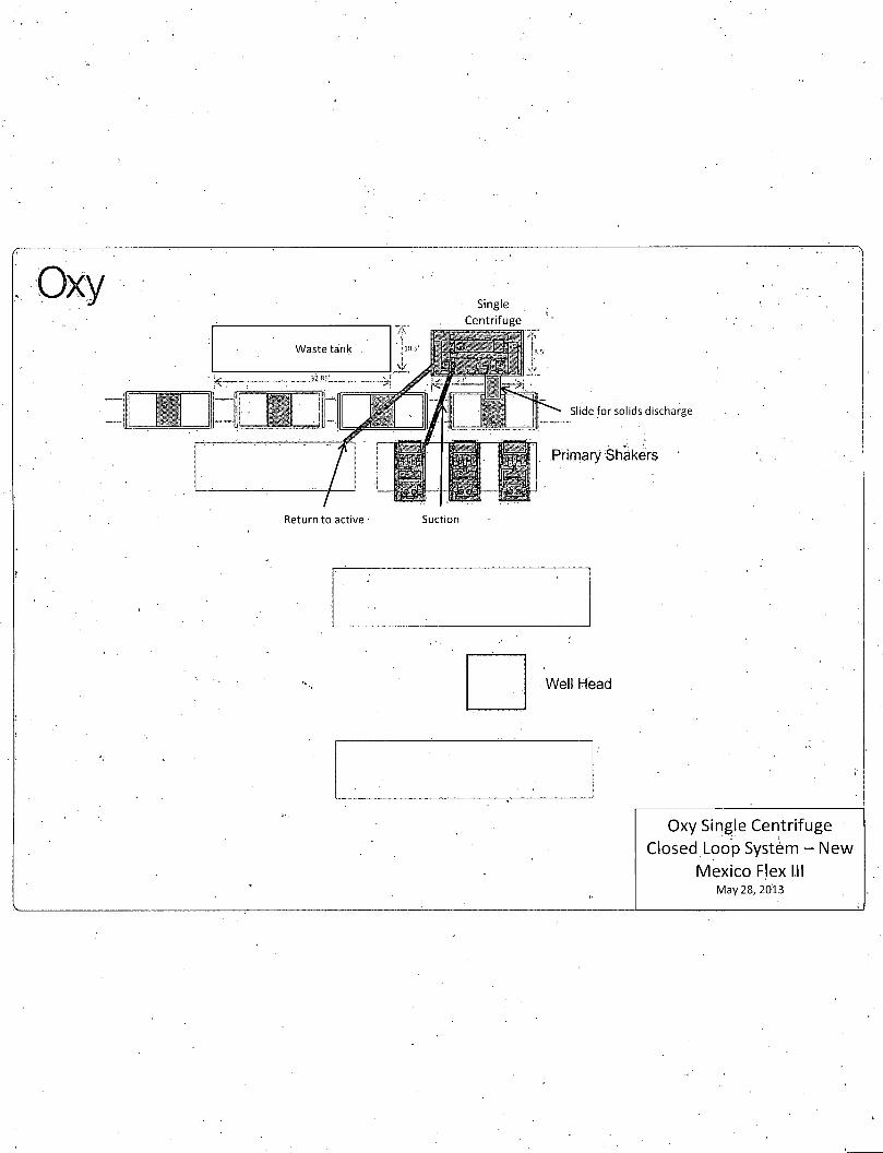
^ We will be using a closed-loop system in lieu of lined pits
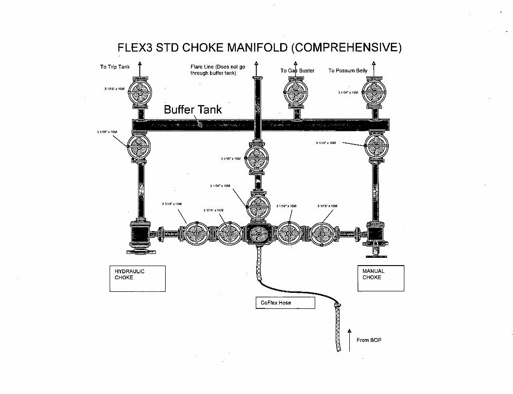
Casing/Cement Program: Additional Comments Proposed Mud Program: 0-600' Fresh Water/Spud Mud - 600-1700' Fresh Water/NaCI Brine - 1700-8800' Cut Brine/Sweeps - 8800-11170' Duo Vis/Salt Gel/Starch/PAC. BOP Program: 13-5/8" 10M three ram stack w/ 5M annular, 5M choke manifold. Additional information will be sent along with the H2S plan.
22. Proposed Blowout Prevention.Program Type Working Pressure Test Pressure Manufacturer
Double Ram 10000 10000
Annular 5000 5000
23. I hereby certify that the information given above is true and complete to the best of my knowledge and belief. I further certify I have complied with 19.15.14.9 (A) NMAC E9 and/or 19.15.14.9 (B) NMAC B3, if applicable.
Signature:
OIL CONSERVATION DIVISION
Printed Name: Electronically filed by KAREN M SINARD Approved By: f^. Ks~UI ' / \
Title: Title: (-r&pcpwy/ / / Email Address: [email protected] Approved Date: / £ • /2-/2^>/J£ I ExPiration G a X e /2/?J2£>/£ Date: 11/12/2013 | Phone: 713-366-5485 Conditions of ApprovalAtt/ched / /
•v v /T n -f o t *2 1 1 / n / o m "j
Operator Name/Number: OXY USA WTP LP 192463 Lease Name/Number: OXY Boo 9 State #2H Pool Name/Number: Undesignated Bone Spring Surface Location: 1700 FNL 150 FEL H Sec 9 T23S R26E State Lease No. VO-4555 Penetration Point: 1700 FNL 330 FEL H Sec 9 T23S R26E Bottom Hole Location: 1700 FNL 350 FWL E Sec 9 T23S R26E
Interval OD Csg Weight Collar Grade Condition Collapse Design Factor
Burst Design Factor
Tension Design Factor
14-3/4" 0-600' 11-3/4" 47 BT&C [ J55 | New 6.43 1.42 5.96 Hole filled with 8.5# Mud 1514# 3072#
10-5/8" • 0-1700' 8-5/8" 32' LT&C | J-55 | New 4..51 1.35 2.87 Hole filled with 10.2#Mud 2533# 3928#
7-7/8" 0-11170' 5-1/2" 17 BT&C | L-80 | New 1.99 1.23 2.02 Hole filled with 9.2# Mud 6285# 7740#
Collapse and burst loads calculated using Stress Check with anticipated loads
Cement Program: a. 11-3/4" Surface Circulate cement to surface w/ 170sx PPC cmt w / 1 % CaCI2 + 4% Bentonite + .125#/sx
Poly-E-Flake, 13.5ppg 1.73 yield 800# 24hr CS 125% Excess followed by 220sx PPC cmt w / 1 % CaCI2, 14.8ppg 1.34 yield 1200# 24hr CS 125% Excess
b. 8-5/8" Intermediate Circulate cement to surface w/ 230sx HES Light PPC cmt w/ 5% salt + 2#/sx Kol-Seal.+ .125#/sx Poly-E-Flake, 12.9ppg 1.86 yield 550# 24hr CS 105% Excess followed by 170sx PPC cmt w / 1 % CaCI2, 14.8ppg 1.34 yield 1400#24hrCS 105% Excess
c. Pilot Hole Plug Plug #1 cement w/ 300sx 50/50 Poz/PPC cmt w/ .3% HR-601 + .3% CFR-3, 14.4ppg 1.23 yield 1275# 24hr CS 35% Excess from 8800' to +/-8000' Plug #2 cement w/ 300sx 50/50 Poz/PPC cmt w/ .3% HR-601 + .3% CFR-3, 14.4ppg 1.23 yield 1275# 24hr CS 35% Excess from 8000' to +/-7200' Plug #3 cement w/ 300sx 50/50 Poz/PPC cmt w/ .3% HR-601 + .3% CFR-3, 14.4ppg 1.23 yield 1275# 24hr CS 35% Excess from 7200' to +/-6400' Plug #4 cement w/31 Osx CI H cmt w/.25% HR-601 + .75% CFR-3, 18ppg, .89 yield 697# 24hr CS 35% Excess from 7200' to +/- 5800'
d. 5-1/2' Production Cement w/ 600sx PP cmt w/ 14.8#/sx Silicalite 50/50 Blend + 15#/sx Scotchlite HGS-6000 + 3#/sx Kol-Seal + .125#/sx Poly-E-Flake + .25#/sx HR-800, 10.2ppg 2.94 yield 947# 24hr CS 100% Excess followed by 700sx Super H cmt w/ 3#/sx salt + .4% CFR-3 + .5% Halad-344 + .3% HR-800 + .125#/sx Poly-E-Flake, 13.2ppg 1.66 yield 615# 24hr CS 40% Excess. Calc TOC-1200'
Description of Cement Additives: Calcium Chloride, Salt (Accelerator); Silicalite (Additive Material); CFR-3 (Dispersant); Bentonite, Schotchlite HGS-6000 (Light Weight Additive);
Kol-Seal, Poly-E-Flake (Lost Circulation Additive); Halad-344 (Low Fluid Loss Control); HR-601, HR-800 (Retarder) The above cement volumes could be revised pending the caliper measurement.
PPQ sec Loss 0 - 600' 8.5 28-38 NC Fresh Water/Spud Mud 600- 1700' 10.2 28-32 NC Fresh water/NaCI Brine 1700- 8800' (Pilot Hole) 9.2 28-34 NC Cut Brine/Sweeps 8800 - 11170' (Curve-Lateral) 9 2 32-50 <18 Duo Vis/Salt Gel/Starch/PAC • Pump high viscosity sweeps as needed for hole cleaning. The mud system will be monitored visually/manually as well as with an electronic PVT. The necessary mud products for additional weight and fluid loss control will be on location at all times.
Fresh water may be present above the Rustler formation, which will cover potential fresh water sources.
Surface casing will be set below the top of the Rustler,
A closed loop system will be utilized consisting of above ground steel tanks and haul-off bins. Disposal of liquids, drilling fluids and cuttings will be disposed of at an approved facility.
Districtl 1625 N. French Dr, Hobbs, NM SS240 Pboae:(57S) 3934161 Fax: (575)393-0720 District!! SI IS. First St, Artesia, NM SS2I0 Phase: (575) 74S-I2S3 Fax: (575) 74S-9720 District m 1000 Rio Brians Ko*t Aztec, NM S7410 Pboae: (505) 334-6178 Fix: (SOS) 334-6170 District IV 1220S.SI Francis Dr., Sana Fe, NM S7505 Phone: (505) 476-3460 Fix: (505) 476-3462
State of New Mexico Energy, Minerals & Natural Resources Department
OIL CONSERVATION DIVISION 1220 South St. Francis Dr.
Santa Fe, NM 87505
Form C-102 Revised August 1, 2011
Submit one copy to appropriate District Office
• AMENDED REPORT
WELL LOGA TION AND A CREAGE DEDICA TIONPLA T API Number
Target Name - hit/miss target ' Dip Angle -Dip Dir ' TVD +N/-S +E/-W Northing Easting - Shape n - n (usft) - (usft) (usft) (usft) (usft) Latitude Longitude
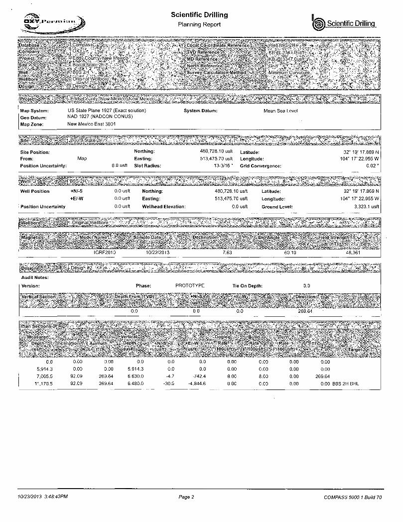
B9S 2H PP 0.00 0.00 6,388.6 -1 .1 -180.0 480,727.00 513,295.70 32° 19' 17.858 N 104° 17' 25.052 W - plan misses target center by 0.3usft at 6433.Ousft MD (6388.8 TVD -1.1 N, -179.8 E) - Point
B9S 2H BHL 0.00 0.00 6,480.0 -30.5 . -4,844.'6 480,697.60 508,631.10, 32° 19' 17.583 N 104° 18' 19.414 W - plan hits target center - Point
® - * !/!&'-SGU FLAWCa M> GATC V^Lit WIW DOUBLE * O W HfllSAUUI
J > - ? t / l t ' - t o v roxn to CIS CATt w u t
g>- j t/ir-iou FUUCE! ew> ct€o; v«.« ® - M U S l £ STODCOl
SHAFFER 8OLTE3-C0VER SPHERICAL ANNULAR PREVENTER, (API IcA UONOCRAMWED. 13 5 / E " - 5 M WP). 10M BOTTOM FLANGE . 5M STUDDED TUP (WEIGHT - 1A..JOQ LBS WITH SHAFFER API 15A HOT OIL RESISTANT ACRYLGNiTPJL£ ELEMENT)
CAMERON UM DOUBLE RAU-TTPE PRESENTER (API ISA MONOGRAMWED, 13 5 / f i " - 1 0 M WP). WITH 5" CWEROH PIPE RAUS (CAMSAM FRONT PACKERS & TOP SEALS) IN TOP CAVrrY AND CAMERON' DS SHEARING BUND RAMS IN BOTTOM CAVITY. BOTTO ELAKtE. i ".ST'JDLIED ,TGP, '(WEIGHT ^=^2 i . iOC'.L3S; 'ATTH RAMS)'
, : " , v I > / S ?
CnCRBN "CP1LUKS<SPXL . . . , . . ,iAPI • • i tA • MONfJGfAyV El)).
T ^ c r T I . FL-M.E1 B TTCV WITH'A . ! / ,15/ r lOV-wp/FLANGEC OUTLETS
(WEIGHT'APFSOXII.IATELY-I
OiME-iON.lWiSIHGLEvSAU-rryE
PREvDnER:{APU'6A> -1
yONOGKA^MED. l 2 ; . 5 / 5 " - : 0 M - S
im>y-tiHO&t>mv RAMS
C m - t . V F « . T P A O E P a ( T~P
SEALSj'BOnOM I F U T O R .
STuC-DE£v.TO»i
«B6HT.* mmm
SEE LIFT LUG DETAIL
H&P FURNISHED :— 13 5/8" -10M x 13 S/8--5M ADAPTER SPOOL 2' - 0- LONG
— J-S-fcrSED'-
PROIJRIETARY , T W 3 . B R i * r C ' ^ ; . r > f f i 1 l ^ ! ^
LN* Th15'0?>.lM,JG.'*FE R ^ T O ' i r - i ASfj < iKE MCT.'.TO.aE f
ft'lTHQUr W E ; ^ C R : - « S f T X ^ l X « E * T ^ ^
(rapHLLMlLHICH & PAYML II Uufru INTFRNATI0N4I DRITIIMi CO
E EE r ^ I U*TE' HOE;;-- . . .
"FIEXRIGS'
HOE;;-- . . .
"FIEXRIGS' A - A -
J h •i.'XOEn'SHEET 03
y'JCKBJt ^r.D. UUUf.rU.iT1 XUT>..\
HOE;;-- . . .
"FIEXRIGS'
\ vavES?i.'-L-~* leS'Do.wurjKD
'JLJC -
/• H ' V * L \
E FLE
_._\ 6 J >Gjfv'EnE3!BO(*'5r*:i-:r : u*L' I J«C; ,M>* SEV,
210-P1-07 E • &E> ' •0r - -1 HEET^
I J«C; ,M>* SEV,
210-P1-07 E
-11-3/4"
-8-5/8"
-5-1/2"
Permian Basin t A M E R O
Jeanette 1-31-13 # 21073221 Date working I'rcaurc:
FLEX3 STD CHOKE MANIFOLD (COMPREHENSIVE)
10M REMOTE V. -f
KILL LINE SCHEMATIC >
From Mud Pumps
To Stand Pipe
To Choke Manifold
A „
HCR
KILL LINE
Choke Manifold - Gas Separator (Top View)
Choke Line from BOP
Mud Inlet from buffer tank in the Choke Manifold
Choke Manifold - Gas Separator (Side View)
+ 1
4>
Mud Outlet to Possum Belly or Trip Tank
Gas Outlet to Flare Line
Gas Outlet to Flare Line
Gas Separator Routing Flex I I I Rigs
Oxy Single Centrifuge Closed Loop System - New
Mexico Flex III May 28, 2013
Oxy
Well Head
Oxy Single Centrifuge Closed Loop System - New
Mexico Flex III May 28, 2013
SECTION 9, TOWNSHIP 23 SOUTH, RANGE 26 EAST, N.M.P.M., EDDY COUNTY NEW MEXICO
N89"45'36"E - 2665.9'.
GLO 1/4 3.C. "1943" — — ® -
N89'31'36"E 2681.5'
GRID AZ. = 269'38'17" 4844.80' IN ALL
BOTTOM HOLE LOCA TION
PENETRATION POINT
SURFACE LOCATION BOO "9" STATE #211
<k GLO 1/4 B.C. "1943"
DRIVING DIRECTIONS'. BEGINNING IN CARLSBAD AT THE INTERSECTION OF HWY. #285 AND • HWY. #62, GO SOUTH ON HWY. #62 FOR 5.4 MILES. TURN' RIGHT ON COUNTY ROAD #765 (GILLOCK ROAD) AND GO WEST/SOUTHWEST FOR 0.8 MILES, CONTINUE WEST FOR 0.2 'MILES. TURN LEFT AND GO SOUTH FOR. 0.2 MILES. TURN RIGHT AND GO WEST FOR 0.5 MILES, GO NORTH FOR 0.4 MILES, TURN LEFT AND -GO WEST FOR 0.1 MILES, CONTINUE WEST ON PROPOSED ROAD FOR 321.2 FEET TO LOCATION.
SURVEYORS CERTIFICATE
I, TERRY J. ASEL. NEW MEXICO PROFESSIONAL SURVEYOR NO. .15079, DO HEREBY CERTIFY THAT I CONDUCTED AND AM RESPONSIBLE FOR THIS SURVEY, THAT THIS SURVEY IS TRUE AND CORRECT TO THE BEST OF MY KNOWLEDGE AND BELIEF, AND MEETS THE "MINIMIUM STANDARDS FOR SURVEYING IN NEW MEXICO" AS ADOPTED BY THE NEW MEXICO STATE BOARD OF REGISTRATION FOR PROFESSIONAL ENGINEERS AND SURVEYORS.
LEGEND ® - DENOTES FOUND MONUMENT AS NOTED » - DENOTES CALCULATED CORNER
1000 0 fcCE3=CHZB_1=
1000' 2000' FEET
SCALE: = 1000'
Asel Surveying P.O. BOX 393 - 3-0 W. TAYLOR
HOBBS. NEW MEXICO - 575-393-9146
OXY USA INC. BOO "9" STATE #2H LOCATED AT
1700' FNL & 150' FEL IN SECTION 9, TOWNSHIP 23 SOUTH,' RANGE 26 EAST, N.M.P.M., EDDY COUNTY, NEW MEXICO
Survey Dote: 09 /13 /13
W.O. Number: 13091,3WL-g,
Date: 09 /18 /13
Sheet 1 of 1 Sheets
Drown By: KA
130'913WL-a.'DWG
Rev:
Scale: 1"= 1000
OXY USA INC. BOO "9" STATE #2H
SITE PLAN
BOO 3 STATE #2H
ELEV. 3323.1' (NA D 2 7)
LAT.~32:3216303°N LONC. = t 04.2897096°*
3324.8'r- 13321.5' READ & STEVENS. INC. BANDIT STATE #6
IS
: = = - = z-r\i
3322.4' <t PROPOSED ROAD 321.2'
''fe I I *
II •I I II II 11
LEGEND •• DENOTES PROPOSED WELL PAD
DENOTES PROPOSED ROAD.'
SURVEYORS CERTIFICATE
I, TERRY J. ASEL, NEW MEXICO PROFESSIONAL SURVEYOR NO! 15079, DO HEREBY CERTIFY THAT I CONDUCTED AND AM RESPONSIBLE FOR THIS SURVEY, THAT THIS SURVEY IS TRUE AND CORRECT TO THE BEST OF MY KNOWLEDGE AND BELIEF, AND MEETS THE "MINIMiUM STANDARDS FOR SURVEYING IN NEW MEXICO" AS ADOPTED BY THE NEW MEXICO STATE BOARD OF REGISTRATION FOR PROFESSIONAL ENGINEERS AND SURVEYORS.
R.P.L.S: No. 15079
Asel Surveying . 'P.O. BOX 393 - 310 W. TAYLOR HOBBS, NEW MEXICO - 575-393-9146 '
300' 0 h H H M H ^
.. 300'. 600' FEET
SCALE: 1"=300'
OXY USA. INC. BOO "9" STATE #2H WELL PAD LOCATED AT
1700' FNL & 150' FEL IN SECTION 9, TOWNSHIP 23 SOUTH, RANGE 26 EAST, N.M.P.M'., EDDY COUNTY, NEW MEXICO.
Survey Do te : 0 9 / 1 3 / 1 3
W.O. • N u m b e n . 1 3 0 9 . 1 . 3 W L - 0
Do te : 0 9 / 1 8 / 1 3 .
Shee t 1 o f 1 S h e e t s
D rown By: KA
1 3 0 9 1 3 W L - O
Rev:
Sca le :1 " = 3 0 0 '
LOCATION VERIFICATION MAP
SCALE: 1 2000 CONTOUR INTERVAL: 10
SEC. 9 TWP. 23-S RGE. 26-E
SURVEY. N.M.P.M.
COUNTY EDDY
DESCRIPTION 1700' FNL & 150' PEL
ELEVATION 3323. V
OXY USA INC. OPERATOR_
LEASE BOO "ff" STATE #2H
U.S.G.S. TOPOGRAPHIC MAP KITCHEN COVE, N.M. , .
Asel Surveying P.O. BOX 393, - 310'W. TAYLOR
HOBBS, NEW MEXICO - "575-393-9146
VICINITY MAP
LEASE BOO "9" STATE #2H
DIRECTIONS BEGINNING IN CARLSBAD AT THE INTERSECTION OF HWY. #285 AND HWY. #62, GO SOUTH ON HWY. #62 FOR 5.4 MILES, TURN RIGHT ON COUNTY ROAD #765 (GILLOCK ROAD) AND GO WEST/ SOUTHWEST FOR 0.8 MILES, CONTINUE WEST FOR 0.2 MILES, TURN LEFT AND GO SOUTH FOR 0.2 MILES,. TURN RIGHT AND GO WEST FOR 0.5 MILES. GO NORTH FOR 0.4 MILES, TURN LEFT. AND GO WEST FOR 0.1 MILES, CONTINUE WEST ON PROPOSED ROAD FOR 321.2 FEET TO LOCATION.
Permian Drilling Hydrogen Sulfide Drilling Operations Plan
New Mexico
Scope
This contingency plan establishes guidelines for the public, all company employees, and contract employees who's work activities may involve exposure to hydrogen sulfide (H2S) gas. While drilling this well, it is possible to encounter H2S bearing formations. At all times, the first barrier to control H2S emissions will be the drilling fluid, which will have a density high enough to control influx.
Objective
1. Provide an immediate and predetermined response plan to any condition when H2S is detected. All H2S detections in excess of 10 parts per million (ppm) concentration are considered an Emergency.
2. Prevent , any and all accidents, and prevent the uncontrolled release of hydrogen sulfide into the atmosphere.
3. Provide proper evacuation procedures to cope with emergencies..
4. Provide immediate and adequate medical attention should an injury occur.
- 1 -
Discussion
Implementation:"
Emergency response Procedure:
Emergency equipment Procedure:
Training provisions:
Drilling emergency call lists:
Briefing:
Public safety:
This plan with all details is to be fully implemented before drilling to commence.
This section outlines the conditions and denotes steps to be taken in the. event of an emergency.
This section outlines the safety and emergency-equipment that will be required for the drilling of this well.
This section outlines the training provisions that must be adhered to prior to drilling.
Included are the telephone numbers of all persons to be contacted should an emergency exist. •
This section deals with the briefing of all people involved in the drilling operation.
Public safety personnel will be made aware of any potential evacuation and any additional support needed. - '
Check lists: Status check lists and procedural check lists have been included to insure adherence to the plan.
General information: A general information section has been included to supply support information.
Hydrogen Sulfide Training
All personnel, whether regularly assigned, contracted, or employed on an unscheduled basis, will receive training from a qualified instructor in the following areas prior to commencing drilling operations on the well:
1. The hazards and characteristics of H2S. 2. Proper use and maintenance of personal protective equipment and life support
systems. 3. H2S detection. 4. Proper use of H2S detectors, alarms, warning systems, briefing areas, evacuation
procedures and prevailing winds. 5. Proper techniques for first aid and rescue procedures. 6. Physical effects of hydrogen sulfide on the human body. 7. Toxicity of hydrogen sulfide and sulfur dioxide. 8. Use of SCBA and supplied air equipment. 9. First aid and artificial respiration. 10. Emergency rescue.
In addition, supervisory personnel will be trained in the following areas:
1. The effects of H2S on metal components. If high tensile strength tubular is to be used, personnel will be trained in their special maintenance requirements.
2. Corrective action and shut-in procedures when drilling a well, blowout prevention and well control procedures.
3. The contents and requirements of the H2S Drilling Operations Plan.
H2S training refresher must have been taken within one year prior to drilling the well. Specifics on the well to be drilled will be discussed during the pre-spud meeting. H2S and well control (choke) drills will be performed while drilling the well, at least on a weekly basis. This plan shall be available in the well site. All personnel will be required to carry the documentation proving that the H2S training has been taken.
Service company and visiting personnel
A. Each service company that will be on this well will be notified if the zone contains H2S.
B. Each service company must provide for the training and equipment of their employees before they arrive at the well site.
C. Each service company will be expected to attend a well site briefing
Emergency Equipment Requirements
1. Well control equipment
The well shall have hydraulic BOP equipment for the anticipated pressures. Equipment is to be tested on installation and follow Oxy Well Control standard, as well as BLM Onshore Order #2.
Special control equipment:
A. Hydraulic BOP equipment with remote control on ground. Remotely operated choke.
B. Rotating head C. Gas buster equipment shall be installed before drilling out of surface pipe.
2. Protective equipment for personnel
A. Four (4) 30-minute positive pressure air packs (2 at each briefing area) on location.
B. Adequate fire extinguishers shall be located at strategic locations.
C. Radio / cell telephone communication will be available at the rig.
Rig floor and trailers. Vehicle.
3. Hydrogen sulfide sensors and alarms
A. H2S sensor with alarms will be located on the rig floor, at the bell nipple, and at the flow line. These monitors will be set to alarm at 10 ppm with strobe light, and audible alarm.
B. Hand operated detectors with tubes. C. H2S monitor tester (to be provided by contract Safety Company.) D. There shall be one combustible gas detector on location at all times.
4. Visual Warning Systems
A. One sign located at each location entrance with the following language:
Caution - potential poison gas Hydrogen sulfide No admittance without authorization
-4 -
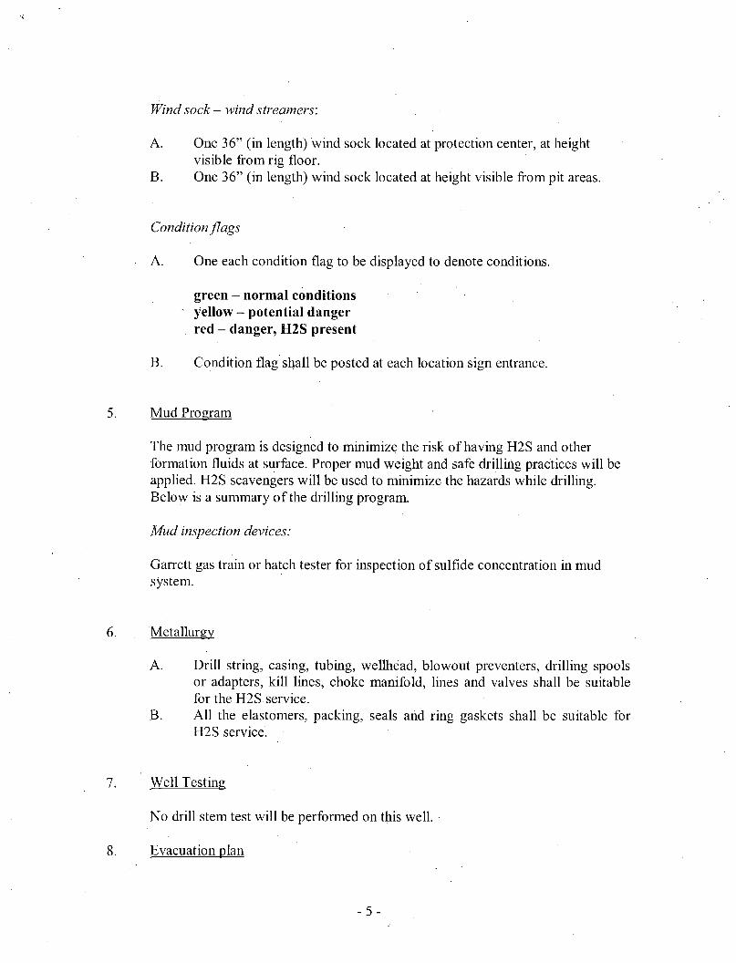
Wind sock — wind streamers:
A. One 36" (in length) wind sock located at protection center, at height visible from rig floor.
B. One 36" (in length) wind sock located at height visible from pit areas.
Condition flags
A. One each condition flag to be displayed to denote conditions.
green - normal conditions yellow - potential danger red - danger, H2S present
B. Condition flag shall be posted at each location sign entrance.
5. Mud Program
The mud program is designed to minimize the risk of having H2S and other formation fluids at surface. Proper mud weight and safe drilling practices will be applied. H2S scavengers will be used to minimize the hazards while drilling. Below is a summary of the drilling program.
Mud inspection devices:
Garrett gas train or hatch tester for inspection of sulfide concentration in mud system.
6. Metallurgy
A. Drill string, casing, tubing, wellhead, blowout preventers, drilling spools or adapters, kill lines, choke manifold, lines and valves shall be suitable for the H2S service.
B. All the elastomers, packing, seals and ring gaskets shall be suitable for H2S service.
7. Well Testing
No drill stem test will be performed on this well.
8. Evacuation plan
- 5 -
Evacuation routes should be established prior to well spud for each well and discussed with all rig personnel.
9. Designated area
A. Parking and visitor area: all vehicles are to be parked at a predetermined safe distance from the wellhead.
B. There will be a designated smoking area. C. Two briefing areas on either side of the location at the maximum
allowable distance from the well bore so they offset prevailing winds perpendicularly, or at a 45-degree angle if wind direction tends to shift in the area.
Emergency procedures
A. In the event of any evidence of H2S level above 10 ppm, take the following steps:
1. The Driller will pick up off bottom, shut down the pumps, slow down the pipe rotation.
2. Secure and don escape breathing equipment, report to the upwind designated safe briefing / muster area.
3. All personnel on location will be accounted for and emergency search should begin for any missing, the Buddy System will be implemented.
4. Order non-essential personnel to leave the well site, order all essential personnel out of the danger zone and upwind to the nearest designated safe briefing / muster area.
5. Entrance to the location will be secured to a higher level than our usual "Meet and Greet" requirement, and the proper condition flag will be displayed at the entrance to the location.
6. Take steps to determine if the H2S level can be corrected or suppressed and, if so, proceed as required.
B. If uncontrollable conditions occur:
1. Take steps to protect and/or remove any public in the down-wind area from the rig - partial evacuation and isolation. Notify necessary public safety personnel and appropriate regulatory entities (i.e. BLM) of the situation.
- 6 -
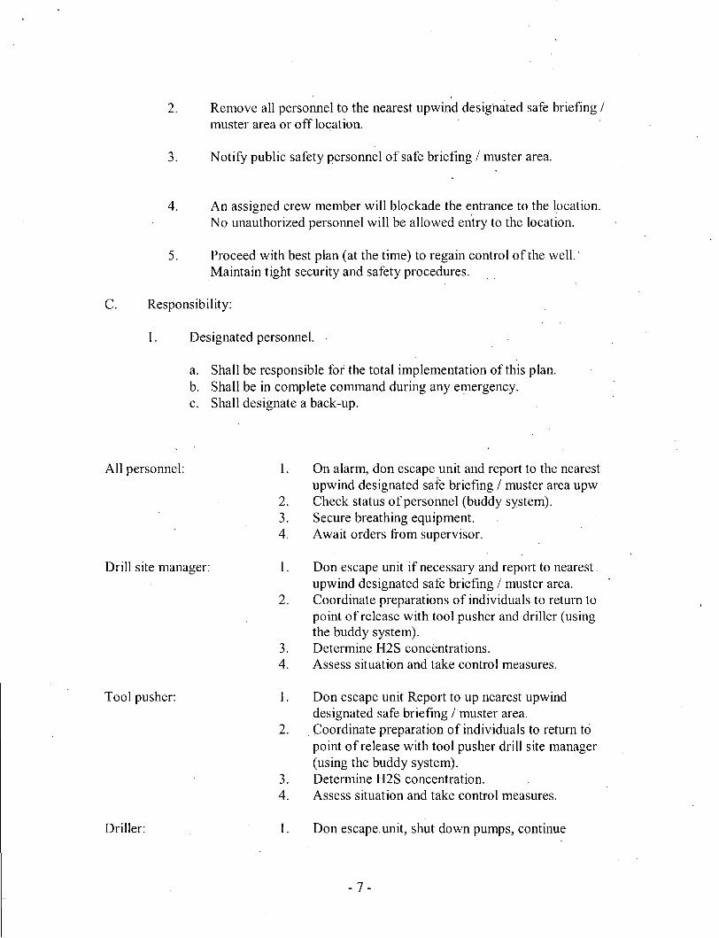
2. Remove all personnel to the nearest upwind designated safe briefing / muster area or off location.
3. Notify public safety personnel of safe briefing / muster area.
4. An assigned crew member will blockade the entrance to the location. No unauthorized personnel will be allowed entry to the location.
5. Proceed with best plan (at the time) to regain control of the well.' Maintain tight security and safety procedures.
C. Responsibility:
1. Designated personnel.
a. Shall be responsible for the total implementation of this plan. b. Shall be in complete command during any emergency. c. Shall designate a back-up.
All personnel: 1. On alarm, don escape unit and report to the nearest upwind designated safe briefing / muster area upw
2. Check status of personnel (buddy system). 3. Secure breathing equipment. 4. Await orders from supervisor.
Drill site manager: 1. Don escape unit if necessary and report to nearest upwind designated safe briefing / muster area.
2. Coordinate preparations of individuals to return to point of release with tool pusher and driller (using the buddy system).
3. Determine H2S concentrations. 4. Assess situation and take control measures.
Tool pusher: 1. Don escape unit Report to up nearest upwind designated safe briefing / muster area.
2. Coordinate preparation of individuals to return to point of release with tool pusher drill site manager (using the buddy system).
3. Determine H2S concentration. 4. Assess situation and take control measures.
Driller: 1. Don escape, unit, shut down pumps, continue
rotating DP. Check monitor for point of release. Report to nearest upwind designated safe briefing / muster area. Check status of personnel (in an attempt to rescue, use the buddy system). Assigns least essential person to notify Drill Site Manager and tool pusher by quickest means in case of their absence. Assumes the responsibilities of the Drill Site Manager and tool pusher until they .arrive should they be absent.
Will remain in briefing / muster area until instructed by supervisor.
Report to nearest upwind designated safe briefing / muster area. " When instructed, begin check of mud for ph and H2S level. (Garett gas train.)
Mask up and check status of all personnel and secure operations as instructed by drill site manager.
Taking a kick
When taking a kick during,an H2S emergency, all personnel will follow standard Well control procedures after reporting to briefing area and masking up.
Open-hole logging
All unnecessary personnel off floor. Drill Site Manager and safety personnel should monitor condition, advise status and determine need for use of air equipment.
Running casing or plugging
Following the same "tripping" procedure as above. Drill Site Manager and safety personnel should determine if all personnel have access to protective equipment.
2. 3.
4.
5.
Derrick man 1. Floor man #1 Floor man #2
Mud engineer: 1.
• 2.
Safety personnel: 1.
Ignition procedures
The decis ion to ignite the well is the responsibility of the operator (Oxy Drilling Management). The decision should be made only as a last resort and in a situation where it is clear that:
1. Human life and property are endangered. 2. There is no hope controlling the blowout under the prevailing conditions
at the well.
Instructions for igniting the well
1. Two people are required for the actual igniting operation. They must wear self-contained breathing units and have a safety rope attached. One man (tool pusher or safety engineer) will check the atmosphere for explosive gases with the gas monitor. The other man is responsible for igniting the well.
2. Primary method to ignite: 25 mm flare gun with range of approximately 500 feet.
3. Ignite upwind and do not approach any closer than is warranted. 4. Select the ignition site best for protection, and which offers an easy escape
route. 5. Before firing, check for presence of combustible gas. 6. After lighting, continue emergency action and procedure as before. 7. All unassigned personnel will remain in briefing area until instructed by
supervisor or directed by the Drill Site Manager.
Remember: After well is ignited, burning hydrogen sulfide will.convert to sulfur dioxide, which is also highly toxic. Do not assume the area is safe after the well is ignited.
-9 -
Status check list
Note: All items on this list must be completed before drilling to production casing point.
1. H2S sign at location entrance.
2. Two (2) wind socks located as required.
3. Four (4) 30-minute positive pressure air packs (2 at each Briefing area) on location for all rig personnel and mud loggers.
4. Air packs inspected and ready for use.
5. Cascade system and hose line hook-up as needed.
6. Cascade system for refilling air bottles as needed.
7. Condition flag on location and ready for use.
8. H2S detection system hooked up and tested.
9. H2S alarm system hooked up and tested.
10. Hand operated H2S detector with tubes on location.
11. 1-100' length of nylon rope on location.
12. All rig crew and supervisors trained as required.
13. All outside service contractors advised of potential H2S hazard on well.
14. No smoking sign posted and a designated smoking area identified.
15. Calibration of all H2S equipment shall be noted on the IADC report.
- 10-
Procedural check list during H2S events
Perform each tour:
1. Check fire extinguishers to see that they have the proper charge.
2. Check breathing equipment to ensure that it in proper working order.
3. Make sure all the H2S detection system is operative.
Perform each week:
1. Check each piece of breathing equipment to make sure that demand or forced air regulator is working. This requires that the bottle be opened and the mask assembly be put on tight enough so that when you inhale, you receive air or feel air flow.
2. BOP skills (well control drills).
3. Check supply pressure on BOP accumulator stand by source.
4. Check breathing equipment mask assembly to see that straps are loosened and turned back, ready to put on.
5. Check pressure on breathing equipment air bottles to make sure they are charged to full volume. ( Air quality checked for proper air grade "D" before bringing to location)
6. Confirm pressure on all supply air bottles.
7. Perform breathing equipment drills with on-site personnel.
8. Check the following supplies for availability.
A. Emergency telephone list. B. Hand operated H2S detectors and tubes.
General evacuation plan
1. When the company approved supervisor (Drill Site Manager, consultant, rig pusher, or driller) determines the H2S gas cannot be limited to the well location and the public will be involved, he will activate the evacuation plan.
2. Drill Site Manager or designee will notify local government agency that a hazardous condition exists and evacuation needs to be implemented.
3. Company or contractor safety personnel that have been trained in the use of H2S detection equipment and self-contained breathing equipment will monitor H2S concentrations, wind directions, and area of exposure. They will delineate the outer perimeter of the hazardous gas area. Extension to the evacuation area will be determined from information gathered.
4. Law enforcement personnel (state police, police dept., fire dept., and sheriffs dept.) Will be called to aid in setting up and maintaining road blocks. Also, they will aid in evacuation of the public if necessary.
5. After the discharge of gas has been controlled, company safety personnel will determine when the area is safe for re-entry.
Important: Law enforcement personnel will not be asked to come into a contaminated area. Their assistance will be limited to uncontaminated areas. Constant radio contact will be maintained with them.
- 12-
Emergency actions
Well blowout - if emergency
1. Evacuate all personnel to "Safe Briefing / Muster Areas" or off location if needed.
2. If sour gas - evacuate rig personnel.
3. If sour gas - evacuate public within 3000 ft radius of exposure.
4. Don SCBA and shut well in if possible using the buddy system.
5. Notify Drilling Superintendent and call 911 for emergency help (fire dept and ambulance) if needed.
6. Implement the Blowout Contingency Plan, and Drilling Emergency Action Plan.
6. Give first aid as needed.
Person down location/facility
1. If immediately-possible, contact 911. Give location and wait for confirmation.
2. Don SCBA and perform rescue operation using buddy system.
- 13 -
Toxic effects of hydrogen sulfide
Hydrogen sulfide is extremely toxic. The acceptable ceiling concentration for eight-hour exposure is 10 ppm, which is .001% by volume. Hydrogen sulfide is heavier than air (specific gravity - 1.192) and colorless. It forms an explosive mixture with air between 4.3 and 46.0 percent by volume. Hydrogen sulfide is almost as toxic as,hydrogen cyanide • and is between five and six times more toxic than carbon monoxide. Toxicity data for hydrogen sulfide and various other gases are compared in table i. Physical effects at various hydrogen sulfide exposure levels are shown in table ii.
Table i Toxicity of various gases
Common Chemical Specific Threshold Hazardous Lethal concentration name formula gravity limit limit (3)
100 std. Ff3* 0.001 <10 00.65 Obvious and unpleasant odor.
- 14-
0.002 10 01.30
0.010 100 06.48
0.020 200 12.96
0.050 500 32.96
0.070 700 45.36
0.100 1000 64.30
*at 15.00 psia and 60'f.
Safe for 8 hours of exposure.
Kill smell in 3 - 15 minutes. May sting eyes and throat. Kills smell shortly; stings eyes and throat.
Dizziness; breathing ceases in a few minutes; needs prompt artificial respiration. Unconscious quickly; death will result if not rescued promptly. Unconscious at once; followed by death within minutes.
- 15 -
Use of self-contained breathing equipment (SCBA)
1. Written procedures shall be prepared covering safe use of SCBA's in dangerous atmosphere, which might be encountered in normal operations or in emergencies. Personnel shall be familiar with these procedures and the available SCBA.
2 SCBA's shall be inspected frequently at random to insure that they are properly used, cleaned, and maintained.
3. Anyone who may use the SCBA's shall be trained in how to insure proper face-piece to face seal. They shall wear SCBA's in normal air and then wear them in a test atmosphere, (note: such items as facial hair {beard or sideburns} and eyeglasses will not allow proper seal.) Anyone that may be reasonably expected to wear SCBA's should have these items removed before entering a toxic atmosphere. A special mask must be obtained for anyone who must wear eyeglasses or contact lenses.
4. Maintenance and care of SCBA's:
a. A program for maintenance and care of SCBA's shall include the following: 1. Inspection for defects, including leak checks. 2. Cleaning and disinfecting. 3. Repair. 4. Storage.
b. Inspection, self-contained breathing apparatus for emergency use shall be inspected monthly. 1. Fully charged cylinders. 2. Regulator and warning device operation. 3. Condition of face piece and connections. 4. Rubber parts shall be maintained to keep them pliable and prevent
deterioration.
c. Routinely used SCBA's shall be collected, cleaned and disinfected as frequently as necessary to insure proper protection is provided.
5. Persons assigned tasks that requires use of self-contained breathing equipment shall be certified physically fit (medically cleared) for breathing equipment usage at least annually.
6. SCBA's should be worn when:
A. Any employee works near the top or on top of any tank unless test reveals less than 10 ppm of H2S.
- 16-
B. When breaking out any line where H2S can reasonably be expected.
C. When sampling air in areas to determine if toxic concentrations of H2S exists.
D. When working in areas where over 10 ppm H2S has been detected.
E. At any time there is a doubt as to the H2S level in the area to be entered.
Rescue First aid for H2S poisoning
Do not panic!
Remain calm - think!
1. Don SCBA breathing equipment.
2. Remove victim(s) utilizing buddy system to fresh air as quickly as possible, (go up-wind from source or at right angle to the wind. Not down wind.)
3. Briefly apply chest pressure - arm lift method of artificial respiration to clean the victim's lungs and to avoid inhaling any toxic gas directly from the victim's lungs.
4. Provide for prompt transportation to the hospital, and continue giving artificial respiration if needed.
5. Hospital(s) or medical facilities need to be informed, before-hand, of the possibility of H2S gas poisoning - no matter how remote the possibility is.
6. Notify emergency room personnel that the victim(s) has been exposed to H2S gas.
Besides basic first aid, everyone on location should have a good working knowledge of artificial respiration.