Product Data Sheet VKD Series Automated Ball Valves IPEX VKD Series Automated Ball Valves offer a variety of advanced features such as the patented seat stop carrier, a high quality stem and ball support system, and the new DUAL BLOCK ® system which locks the union nuts, preventing back-off due to vibration or thermal cycling. Deep grooves, thick o-rings, and cushioned Teflon ® seats contribute to strong seals at pressures up to 232psi while an integral mounting flange and support bracketing combine for simple adaptation for actuation and anchoring. VKD Series Automated Ball Valves are part of our complete systems of pipe, valves, and fittings, engineered and manufactured to our strict quality, performance, and dimensional standards. < STANDARDS > ANSI B1.20.1 ASTM D1784 ASTM D2464 ASTM D2466 ASTM D2467 ASTM D4101 ASTM F1498 ASTM F437 ASTM F439 ISO 11922-1 Valve Availability Body Material: PVC, CPVC, PP Size Range: 1/2” through 4” Pressure: 232psi, 150psi (PP) Seats: Teflon ® (PTFE) Seals: EPDM or FPM End Connections: Socket (IPS), Threaded (FNPT), Socket (Metric) Actuator Control: Double Acting Pneumatic, Spring Return Pneumatic, Electric Note: PVDF valves available on request. ipexna.com Toll Free: 866 473-9462
Transcript
Product Data Sheet VKD Series Automated Ball Valves
IPEX VKD Series Automated Ball Valves offer a variety of advanced features such as the patented seat stop carrier, a high quality stem and ball support system, and the new DUAL BLOCK® system which locks the union nuts, preventing back-off due to vibration or thermal cycling. Deep grooves, thick o-rings, and cushioned Teflon® seats contribute to strong seals at pressures up to 232psi while an integral mounting flange and support bracketing combine for simple adaptation for actuation and anchoring. VKD Series Automated Ball Valves are part of our complete systems of pipe, valves, and fittings, engineered and manufactured to our strict quality, performance, and dimensional standards.
End Connections: Socket (IPS), Threaded (FNPT), Socket (Metric)
Actuator Control: Double Acting Pneumatic, Spring Return Pneumatic, Electric
Note: PVDF valves available on request.
ipexna.comToll Free: 866 473-9462
VKD Series Automated Ball Valves
2
Sample Specification Samples Specifications
1.0 Ball Valves - VKD
1.1 Material
• The valve body, stem, ball and unions shall be made of PVC compound which shall meet or exceed the requirements of cell classification 12454 according to ASTM D1784.
or The valve body, stem, ball and unions shall be made of Corzan® CPVC compound which shall meet or exceed the requirements of 23447 according to ASTM D1784.
or The valve body, stem, ball and unions shall be made of stabilized PP homopolymer compound, also containing a RAL 7032 pigment, which shall meet or exceed the requirements of Type I Polypropylene according to ASTM D4101.
1.2 Seats
• The ball seats shall be made of Teflon® (PTFE).
1.3 Seals
• The o-ring seals shall be made of EPDM.
or The o-ring seals shall be made of FPM.
2.0 Connections
2.1 Socket style
• The IPS socket PVC end connectors shall conform to the dimensional standards ASTM D2466 and ASTM D2467.
or The IPS socket CPVC end connectors shall conform to the dimensional standard ASTM F439.
or The Metric socket PP end connectors shall conform to the dimensional standard ISO 11922-1.
2.2 Threaded style
• The female NPT threaded PVC end connectors shall conform to the dimensional standards ASTM D2464, ASTM F1498, and ANSI B1.20.1.
or The female NPT threaded CPVC end connectors shall conform to the dimensional standards ASTM F437, ASTM F1498, and ANSI B1.20.1.
or The female NPT threaded PP end connectors shall conform to the dimensional standards ASTM F1498, and ANSI B1.20.1.
3.0 Design Features
• The valve shall be double blocking with union ends.
• All valves shall be full port.
• All valves shall allow for bi-directional flow.
• The valve body shall be single end entry with a threaded carrier (ball seat support).
• The threaded carrier shall be adjustable with the valve installed.
• The valve body shall have an expansion and contraction compensating groove on the molded end.
• The valve body, union nuts and carrier shall have deep square style threads for increased strength.
• The ball and stem shall be machined smooth to minimize wear on valve seats and seals.
• All valve seats shall have o-ring backing cushions to compensate for wear and prevent seizure of the ball.
• The stem design shall feature double o-ring seals as well as a safety shear point above the o-rings.
• All valves shall have integrally molded mounting features for actuation.
• All valves shall have integrally molded support bracketing for anchoring.
• The valve shall include the Dual Block® union nut locking mechanism.
3.1 Pressure Testing
• All valves shall have been pressure tested in both the open and closed positions by the manufacturer.
3.2 Pressure Rating
• All PVC and CPVC valves shall be rated at 232psi at 73°F.
• All PP valves shall be rated at 150psi at 73°F.
3.3 Markings
• All valves shall be marked to indicate size, material designation, and manufacturers name or trade mark.
3.4 Color Coding
• All PVC valves shall be color-coded dark gray.
or All CPVC valves shall be color-coded light gray.
or All PP valves shall be color coded beige gray.
VKD Series Automated Ball Valves
3
Sample Specification (cont’d)
4.0
All valves shall be Xirtec® PVC, Xirtec® CPVC or SFPP by IPEX or approved equal.
5.0 Actuators
• All Actuators shall be factory installed by IPEX
Pneumatic Actuator:
• Shall be sized for 80 psi control air pressure
• Shall be dual piston rack and pinion design with linear torque output.
• Body shall be Technopolymer UT series or Anodized Aluminum MT series with standard position indicator and NAMUR VDI/VDE 3845 and ISO 5211 mounting dimensions.
• All models shall be operable using air, water, nitrogen or compatible hydraulic fluids from 40 – 120psi.
• Aluminum body models shall feature dual travel stops that provide +/- 10° stroke rotation on both the opening and closing phases.
• All external fasteners shall be stainless steel.
Electric Actuator:
• Shall have 100VAC – 240VAC reversing motors with torque limiters, thermal protection, auxiliary limit switches, NEMA 4X enclosure*, manual override, and position indicator as standard.
or Shall have 24VDC reversing motors with torque limiters, thermal protection, auxiliary limit switches, NEMA 4X enclosure*, manual override, and position indicator as standard.
• 4-20mA positioner, battery backup, and 180° rotation models shall be available in 100 – 240VAC and 24VDC
• All models shall have ISO 5211 mounting dimensions
Positioner (4~20mA or 0~10 VDC) Not Available Upon Request Upon Request Upon Request
Electrical Connections PG11 PG11 PG11 PG11
Weight (LBS) 3.09 5.07 7.28 10.80
MODEL VB015 VB030 VB060 VB110
VERSION H
Nominal Voltage 100V AC 240V AC 100 – 240V AC
Absorbed Current 75mA 25mA 0.3 – 0.2A 0.6 – 0.3A
Absorbed Power 6.6 VA 6 VA 30 – 48VA 60 – 72 VA
VERSION L
Nominal Voltage 24V AC/DC 24V AC/DC 24V AC/DC 24V AC/DC
Absorbed Current 1.2A 0.6A 2.0A 1.0A 3.6A 1.8A 2.0A 1.0A
Absorbed Power 15 VA 24 VA 44 VA 24 VA
Frequency 50/60 HZ
Electric Actuator Power Consumption
* Type 4X Indoor Use Only Enclosure** UL pending
VKD Series Automated Ball Valves
14
Technical Data
Components
# Component1 Insert2 Handle3 Stem O-Ring4 Stem5 Ball Seat6 Ball7 Body8 Support O-Ring for Ball Seat9 Radial Seal O-Ring10 Socket Seal O-Ring11 Support for Ball Seat12 End Connector13 Union Nut
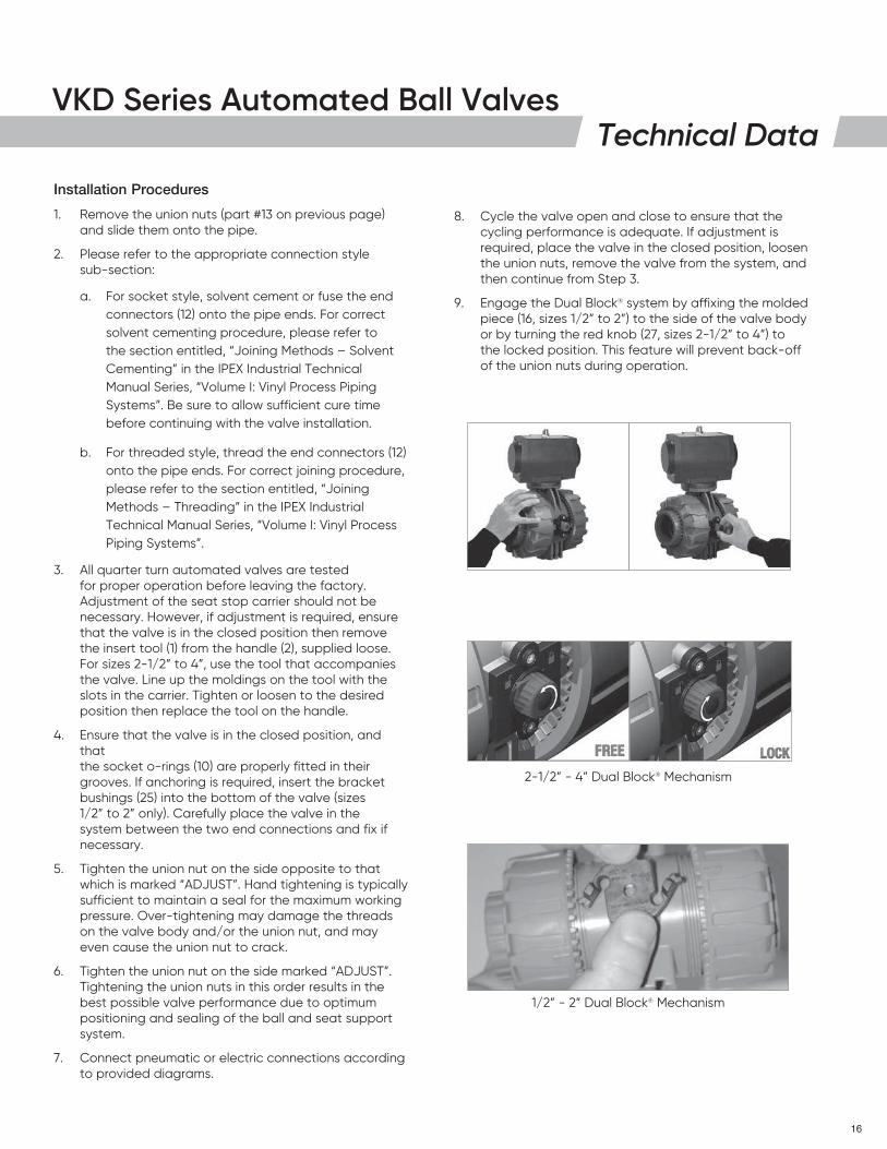
8. Cycle the valve open and close to ensure that the cycling performance is adequate. If adjustment is required, place the valve in the closed position, loosen the union nuts, remove the valve from the system, and then continue from Step 3.
9. Engage the Dual Block® system by affixing the molded piece (16, sizes 1/2” to 2”) to the side of the valve body or by turning the red knob (27, sizes 2-1/2” to 4”) to the locked position. This feature will prevent back-off of the union nuts during operation.
Installation Procedures
1. Remove the union nuts (part #13 on previous page) and slide them onto the pipe.
2. Please refer to the appropriate connection style sub-section:
a. For socket style, solvent cement or fuse the end connectors (12) onto the pipe ends. For correct solvent cementing procedure, please refer to the section entitled, “Joining Methods – Solvent Cementing” in the IPEX Industrial Technical Manual Series, “Volume I: Vinyl Process Piping Systems”. Be sure to allow sufficient cure time before continuing with the valve installation.
b. For threaded style, thread the end connectors (12) onto the pipe ends. For correct joining procedure, please refer to the section entitled, “Joining Methods – Threading” in the IPEX Industrial Technical Manual Series, “Volume I: Vinyl Process Piping Systems”.
3. All quarter turn automated valves are tested for proper operation before leaving the factory. Adjustment of the seat stop carrier should not be necessary. However, if adjustment is required, ensure that the valve is in the closed position then remove the insert tool (1) from the handle (2), supplied loose. For sizes 2-1/2” to 4”, use the tool that accompanies the valve. Line up the moldings on the tool with the slots in the carrier. Tighten or loosen to the desired position then replace the tool on the handle.
4. Ensure that the valve is in the closed position, and that the socket o-rings (10) are properly fitted in their grooves. If anchoring is required, insert the bracket bushings (25) into the bottom of the valve (sizes 1/2” to 2” only). Carefully place the valve in the system between the two end connections and fix if necessary.
5. Tighten the union nut on the side opposite to that which is marked “ADJUST”. Hand tightening is typically sufficient to maintain a seal for the maximum working pressure. Over-tightening may damage the threads on the valve body and/or the union nut, and may even cause the union nut to crack.
6. Tighten the union nut on the side marked “ADJUST”. Tightening the union nuts in this order results in the best possible valve performance due to optimum positioning and sealing of the ball and seat support system.
7. Connect pneumatic or electric connections according to provided diagrams.
2-1/2” - 4” Dual Block® Mechanism
1/2” - 2” Dual Block® Mechanism
VKD Series Automated Ball Valves
17
Technical DataAssembly
Note: Before assembling the valve components, it is advisable to lubricate the o-rings with a water soluble lubricant. Be sure to consult the “IPEX Chemical Resistance Guide” and/or other trusted resources to determine specific lubricant-rubber compatibilities.
1. Replace the stem o-rings (3 or 18), body o-ring (9), ball seat o-rings (8), ball seats (5), and bushings (19, sizes 2-1/2” to 4”) in their proper positions.
2. Insert the stem (4 or 20) into position from inside the valve body (7). On sizes 2-1/2” to 4”, insert the lower stem (21) as well.
3. On sizes 2-1/2” to 4”, replace the actuation adapter plate and affix in position using the bolts (11), washers (14), and nuts (15). Replace the caps (23) over the nuts.
4. Replace the stem extension, if applicable.
5. Carefully insert the ball (6) into the valve body, taking care not to score or damage the outer surface. Ensure that the actuator and ball position correspond to the same operating position.
6. Insert the threaded carrier (11 or 16) and tighten into the valve body. Use the wrench tool to sufficiently tighten.
7. Replace the actuator, if removed, and affix in position using screws (22) installed horizontally (1/2” to 2”) or bolts (3), washers (14), nuts (15), and caps (23) (2-1/2” to 4”).
7. Place the end connectors (12) into the union nuts (13), then thread onto the valve body taking care that the socket o-rings remain properly fitted in their grooves.
8. Engage the Dual Block® system by affixing the molded piece (16, sizes 1/2” to 2”) to the side of the valve body or by turning the red knob (27, sizes 2-1/2” to 4”) to the locked position.
Valves Maintenance
Disassembly
1. If removing the valve from an operating system, isolate the valve from the rest of the line. Be sure to depressurize and drain the valve and isolated branch. It is recommended that all actuators be de-activated before servicing the valve to avoid injury.
2. If necessary, remove actuator connections and detach the valve from the support structure by disassembling the connections to the bracket on the optional bottom of the valve body (7).
3. Unlock the Dual Block® system by compressing the two ends of the molded piece (16, sizes 1/2” to 2”) or by turning the red knob (27, sizes 2-1/2” to 4”) to the unlocked position. Loosen both union nuts (13) and drop the valve out of the line. If retaining the socket o-rings (10), take care that they are not lost when removing the valve from the line.
4. Remove the actuator, if necessary, from the valve by removing the screws (22) located horizontally across from each other (sizes 1/2” to 2”). On sizes 2-1/2” to 4”, remove the actuator by loosening and removing the bolts (3), washers (14), nuts (15), and caps (23).
5. Ensure the valve is in the closed position. If it is not, rotate the ball using the exposed stem or stem extension, making sure not to damage. Line up the moldings on the wrench tool (1, sizes 1/2” to 2”) with the slots in the carrier (found on the side marked “ADJUST”). Loosen and remove the carrier (11 or 16).
6. Carefully press the ball (6) out of the valve body, taking care not to score or damage the outer surface.
7. Press the stem (4 or 20) into the valve body from above. On sizes 2-1/2” to 4”, remove the lower stem (21) by pushing it into the valve body from below.
8. The stem o-rings (3 or 18), body o-ring (9), ball seats (5), ball seat o-rings (8), and bushings (19, sizes 2-1/2” to 4”) can now be removed and/or replaced.
Note: It is not typically necessary to disassemble the Dual Block® components (sizes 2-1/2” to 4”). It is not necessary to remove the actuator from the valve unless the stem requires servicing or replacement. If possible, leave actuator attached to valve during servicing.
VKD Series Automated Ball Valves
18
About IPEX
This literature is published in good faith and is believed to be reliable. However, it does not represent and/or warrant in any manner the information and suggestions contained in this brochure. Data presented is the result of laboratory tests and field experience.
A policy of ongoing product improvement is maintained. This may result in modifications of features and/or specifications without notice.
About the IPEX Group of CompaniesAs leading suppliers of thermoplastic piping systems, the IPEX Group of Companies provides our customers with some of the world’s largest and most comprehensive product lines. All IPEX products are backed by more than 50 years of experience. With state-of-the-art manufacturing facilities and distribution centers across North America, we have established a reputation for product innovation, quality, end-user focus and performance.
Markets served by IPEX group products are:
• Electrical systems• Telecommunications and utility piping systems• Industrial process piping systems• Municipal pressure and gravity piping systems• Plumbing and mechanical piping systems• PE Electrofusion systems for gas and water• Industrial, plumbing and electrical cements• Irrigation systems• PVC, CPVC, PP, PVCO, ABS, PEX, FR-PVDF, NFRPP, FRPP, HDPE, PVDF
and PE pipe and fittings (1/2” – 48”)
Xirtec® is a registered trademark used under license. Xirtec® CPVC piping systems are made with Corzan® CPVC compounds. Corzan® is a registered trademark of the Lubrizol Corporation.