Page 1
UC Regents Fall 2013 © UCBCS 250 L8: Design Verification
2013-9-24Professor Jonathan Bachrach
part one of today’s lecture by John Lazzaro
CS 250 VLSI System Design
Lecture 8 – Design Verification
www-inst.eecs.berkeley.edu/~cs250/
TA: Ben Keller
1Tuesday, September 24, 13
Page 2
UC Regents Fall 2013 © UCBCS 250 L8: Design Verification
multi-site team, necessitating the development of ways tosynchronize the design environment and data (as well asthe design team).
In the following sections of this paper, the designmethodology, clock network, circuits, power distribution,integration, and timing approaches used to meet thesechallenges for the POWER4 chip are described, andresults achieved for POWER4 are presented.
Design methodologyThe design methodology for the POWER4 microprocessorfeatured a hierarchical approach across multiple aspects ofthe design. The chip was organized physically and logically
in a four-level hierarchy, as illustrated in Figure 2.
typically containing 50 000 transistors. Units compriseapproximately 50 related macros, with the microprocessorcore made up of six units. The highest level is the chip,which contains two cores plus the units associated with theon-chip memory subsystem and interconnection fabric.This hierarchy facilitates concurrent design across all fourlevels. While the macros (blocks such as adders, SRAMs,and control logic) are being designed at the transistor and
Figure 1
POWER4 chip photograph showing the principal functional units in the microprocessor core and in the memory subsystem.
Figure 2
Elements in the physical and logical hierarchy used to design the POWER4 chip.
Core Core
Chip
Core
FPU FXU
IFU Unit F
Unit F
Unit F
Macro 1
Unit ZUnit X
Macro n
Macro n
Macro 1
Macro 3
Macro 2
Unit A
Macros, units, core,and chip all generateinitial timing andfloorplan contracts
Memory subsystem
Table 1 Features of the IBM CMOS 8S3 SOItechnology.
Gate Leff 0.09 !mGate oxide 2.3 nm
Metal layers pitch thicknessM1 0.5 !m 0.31 !mM2 0.63 !m 0.31 !mM3–M5 0.63 !m 0.42 !mM6 (MQ) 1.26 !m 0.92 !mM7 (LM) 1.26 !m 0.92 !m
Dielectric "r !4.2
Vdd 1.6 V
Table 2 Characteristics of the POWER4 chip fabricatedin CMOS 8S3 SOI.
Clock frequency ( fc) "1.3 GHzPower 115 W (@ 1.1 GHz, 1.5 V)Transistors 174,000,000
Macros (unique/total) 1015 4341Custom 442 2002RLM 523 2158SRAM 50 181
Total C4s 6380Signal I/Os 2200I/O bandwidth "500 Mb/s
Bus frequency 1/2 fcEngineered wiresBuffers and invertersDecoupling cap 300 nF
J. D. WARNOCK ET AL. IBM J. RES. & DEV. VOL. 46 NO. 1 JANUARY 2002
28
35K
The smallest members of the hierarchy are “macros”
100K
IBM Power 4174 Million TransistorsA complex design ...
96% of all bugs were caught before first tape-out.
First silicon booted AIX & Linux, on a 16-die system.
How ???2Tuesday, September 24, 13
Page 3
UC Regents Fall 2013 © UCBCS 250 L8: Design Verification
Three main components ...(1) Specify chip behavior at the RTL level, and comprehensively simulate it.
(2) Use formal verification to show equivalence betweenVHDL RTL and circuit schematic RTL.
(3) Technology layer: do the the electrons implement the RTL, at speed and power?
Today, we focus on (1).
3Tuesday, September 24, 13
Page 4
UC Regents Fall 2013 © UCBCS 250 L8: Design Verification
Today: Processor Design Verification
Unit testing techniques
Making a processor test plan
State machine testing
How to write test programs
4Tuesday, September 24, 13
Page 5
UC Regents Fall 2013 © UCBCS 250 L8: Design Verification
Lecture Focus: Functional Design Test1600 IEEE JOURNAL OF SOLID-STATE CIRCUITS, VOL. 36, NO. 11, NOVEMBER 2001
Fig. 1. Process SEM cross section.
The process was raised from [1] to limit standby power.
Circuit design and architectural pipelining ensure low voltage
performance and functionality. To further limit standby current
in handheld ASSPs, a longer poly target takes advantage of the
versus dependence and source-to-body bias is used
to electrically limit transistor in standby mode. All core
nMOS and pMOS transistors utilize separate source and bulk
connections to support this. The process includes cobalt disili-
cide gates and diffusions. Low source and drain capacitance, as
well as 3-nm gate-oxide thickness, allow high performance and
low-voltage operation.
III. ARCHITECTURE
The microprocessor contains 32-kB instruction and data
caches as well as an eight-entry coalescing writeback buffer.
The instruction and data cache fill buffers have two and four
entries, respectively. The data cache supports hit-under-miss
operation and lines may be locked to allow SRAM-like oper-
ation. Thirty-two-entry fully associative translation lookaside
buffers (TLBs) that support multiple page sizes are provided
for both caches. TLB entries may also be locked. A 128-entry
branch target buffer improves branch performance a pipeline
deeper than earlier high-performance ARM designs [2], [3].
A. Pipeline Organization
To obtain high performance, the microprocessor core utilizes
a simple scalar pipeline and a high-frequency clock. In addition
to avoiding the potential power waste of a superscalar approach,
functional design and validation complexity is decreased at the
expense of circuit design effort. To avoid circuit design issues,
the pipeline partitioning balances the workload and ensures that
no one pipeline stage is tight. The main integer pipeline is seven
stages, memory operations follow an eight-stage pipeline, and
when operating in thumb mode an extra pipe stage is inserted
after the last fetch stage to convert thumb instructions into ARM
instructions. Since thumb mode instructions [11] are 16 b, two
instructions are fetched in parallel while executing thumb in-
structions. A simplified diagram of the processor pipeline is
Fig. 2. Microprocessor pipeline organization.
shown in Fig. 2, where the state boundaries are indicated by
gray. Features that allow the microarchitecture to achieve high
speed are as follows.
The shifter and ALU reside in separate stages. The ARM in-
struction set allows a shift followed by an ALU operation in a
single instruction. Previous implementations limited frequency
by having the shift and ALU in a single stage. Splitting this op-
eration reduces the critical ALU bypass path by approximately
1/3. The extra pipeline hazard introduced when an instruction is
immediately followed by one requiring that the result be shifted
is infrequent.
Decoupled Instruction Fetch.A two-instruction deep queue is
implemented between the second fetch and instruction decode
pipe stages. This allows stalls generated later in the pipe to be
deferred by one or more cycles in the earlier pipe stages, thereby
allowing instruction fetches to proceed when the pipe is stalled,
and also relieves stall speed paths in the instruction fetch and
branch prediction units.
Deferred register dependency stalls. While register depen-
dencies are checked in the RF stage, stalls due to these hazards
are deferred until the X1 stage. All the necessary operands are
then captured from result-forwarding busses as the results are
returned to the register file.
One of the major goals of the design was to minimize the en-
ergy consumed to complete a given task. Conventional wisdom
has been that shorter pipelines are more efficient due to re-
testing goal
The processor design
correctly executes programs
written in the Instruction Set Architecture
Not manufacturing
tests ...
Intel XScale ARM Pipeline, IEEE Journal of Solid State Circuits, 36:11, November 2001
“Correct” == meets the
“Architect’s Contract”
5Tuesday, September 24, 13
Page 6
UC Regents Fall 2013 © UCBCS 250 L8: Design Verification
Architect’s “Contract with the Programmer”
To the program, it appears that instructions execute in the correct order defined by the ISA.
What the machine actually does is up to the hardware designers, as long as the contract is kept.
As each instruction completes, thearchitected machine state appears to the program to obey the ISA.
Accelerator instructions must define a “contract” ...6Tuesday, September 24, 13
Page 7
UC Regents Fall 2013 © UCBCS 250 L8: Design Verification
When programmer’s contract is broken ...Testing our financial trading system, we found a case where our software wouldget a bad calculation. Once a week or so.
Eventually, the problem turned out to be afailure in a CPU cache line refresh. This was a hardware design fault in the PC.
The test suite included running for two weeks at maximum update rate without error, so this bug was found.
Eric Ulevik7Tuesday, September 24, 13
Page 8
A 475M$ Bug
8Tuesday, September 24, 13
Page 9
UC Regents Fall 2013 © UCBCS 250 L8: Design Verification
Three models (at least) to cross-check.1600 IEEE JOURNAL OF SOLID-STATE CIRCUITS, VOL. 36, NO. 11, NOVEMBER 2001
Fig. 1. Process SEM cross section.
The process was raised from [1] to limit standby power.
Circuit design and architectural pipelining ensure low voltage
performance and functionality. To further limit standby current
in handheld ASSPs, a longer poly target takes advantage of the
versus dependence and source-to-body bias is used
to electrically limit transistor in standby mode. All core
nMOS and pMOS transistors utilize separate source and bulk
connections to support this. The process includes cobalt disili-
cide gates and diffusions. Low source and drain capacitance, as
well as 3-nm gate-oxide thickness, allow high performance and
low-voltage operation.
III. ARCHITECTURE
The microprocessor contains 32-kB instruction and data
caches as well as an eight-entry coalescing writeback buffer.
The instruction and data cache fill buffers have two and four
entries, respectively. The data cache supports hit-under-miss
operation and lines may be locked to allow SRAM-like oper-
ation. Thirty-two-entry fully associative translation lookaside
buffers (TLBs) that support multiple page sizes are provided
for both caches. TLB entries may also be locked. A 128-entry
branch target buffer improves branch performance a pipeline
deeper than earlier high-performance ARM designs [2], [3].
A. Pipeline Organization
To obtain high performance, the microprocessor core utilizes
a simple scalar pipeline and a high-frequency clock. In addition
to avoiding the potential power waste of a superscalar approach,
functional design and validation complexity is decreased at the
expense of circuit design effort. To avoid circuit design issues,
the pipeline partitioning balances the workload and ensures that
no one pipeline stage is tight. The main integer pipeline is seven
stages, memory operations follow an eight-stage pipeline, and
when operating in thumb mode an extra pipe stage is inserted
after the last fetch stage to convert thumb instructions into ARM
instructions. Since thumb mode instructions [11] are 16 b, two
instructions are fetched in parallel while executing thumb in-
structions. A simplified diagram of the processor pipeline is
Fig. 2. Microprocessor pipeline organization.
shown in Fig. 2, where the state boundaries are indicated by
gray. Features that allow the microarchitecture to achieve high
speed are as follows.
The shifter and ALU reside in separate stages. The ARM in-
struction set allows a shift followed by an ALU operation in a
single instruction. Previous implementations limited frequency
by having the shift and ALU in a single stage. Splitting this op-
eration reduces the critical ALU bypass path by approximately
1/3. The extra pipeline hazard introduced when an instruction is
immediately followed by one requiring that the result be shifted
is infrequent.
Decoupled Instruction Fetch.A two-instruction deep queue is
implemented between the second fetch and instruction decode
pipe stages. This allows stalls generated later in the pipe to be
deferred by one or more cycles in the earlier pipe stages, thereby
allowing instruction fetches to proceed when the pipe is stalled,
and also relieves stall speed paths in the instruction fetch and
branch prediction units.
Deferred register dependency stalls. While register depen-
dencies are checked in the RF stage, stalls due to these hazards
are deferred until the X1 stage. All the necessary operands are
then captured from result-forwarding busses as the results are
returned to the register file.
One of the major goals of the design was to minimize the en-
ergy consumed to complete a given task. Conventional wisdom
has been that shorter pipelines are more efficient due to re-
The Chisel RTL model
Chip-level schematic RTL
The “contract” specification“The answer” (correct, we hope).Simulates the ISA model in C. Fast.Better: two models coded independently.
Logical semantics of the Chisel model we will use to create gates. Runs on a software simulator or FPGA hardware.
Extract the netlist from layout, formally verify against Chisel RTL. Catches synthesis bugs. This netlist also used for timing and power.
Where do bugs come from?9Tuesday, September 24, 13
Page 10
UC Regents Fall 2013 © UCBCS 250 L8: Design Verification
Where bugs come from (a partial list) ...1600 IEEE JOURNAL OF SOLID-STATE CIRCUITS, VOL. 36, NO. 11, NOVEMBER 2001
Fig. 1. Process SEM cross section.
The process was raised from [1] to limit standby power.
Circuit design and architectural pipelining ensure low voltage
performance and functionality. To further limit standby current
in handheld ASSPs, a longer poly target takes advantage of the
versus dependence and source-to-body bias is used
to electrically limit transistor in standby mode. All core
nMOS and pMOS transistors utilize separate source and bulk
connections to support this. The process includes cobalt disili-
cide gates and diffusions. Low source and drain capacitance, as
well as 3-nm gate-oxide thickness, allow high performance and
low-voltage operation.
III. ARCHITECTURE
The microprocessor contains 32-kB instruction and data
caches as well as an eight-entry coalescing writeback buffer.
The instruction and data cache fill buffers have two and four
entries, respectively. The data cache supports hit-under-miss
operation and lines may be locked to allow SRAM-like oper-
ation. Thirty-two-entry fully associative translation lookaside
buffers (TLBs) that support multiple page sizes are provided
for both caches. TLB entries may also be locked. A 128-entry
branch target buffer improves branch performance a pipeline
deeper than earlier high-performance ARM designs [2], [3].
A. Pipeline Organization
To obtain high performance, the microprocessor core utilizes
a simple scalar pipeline and a high-frequency clock. In addition
to avoiding the potential power waste of a superscalar approach,
functional design and validation complexity is decreased at the
expense of circuit design effort. To avoid circuit design issues,
the pipeline partitioning balances the workload and ensures that
no one pipeline stage is tight. The main integer pipeline is seven
stages, memory operations follow an eight-stage pipeline, and
when operating in thumb mode an extra pipe stage is inserted
after the last fetch stage to convert thumb instructions into ARM
instructions. Since thumb mode instructions [11] are 16 b, two
instructions are fetched in parallel while executing thumb in-
structions. A simplified diagram of the processor pipeline is
Fig. 2. Microprocessor pipeline organization.
shown in Fig. 2, where the state boundaries are indicated by
gray. Features that allow the microarchitecture to achieve high
speed are as follows.
The shifter and ALU reside in separate stages. The ARM in-
struction set allows a shift followed by an ALU operation in a
single instruction. Previous implementations limited frequency
by having the shift and ALU in a single stage. Splitting this op-
eration reduces the critical ALU bypass path by approximately
1/3. The extra pipeline hazard introduced when an instruction is
immediately followed by one requiring that the result be shifted
is infrequent.
Decoupled Instruction Fetch.A two-instruction deep queue is
implemented between the second fetch and instruction decode
pipe stages. This allows stalls generated later in the pipe to be
deferred by one or more cycles in the earlier pipe stages, thereby
allowing instruction fetches to proceed when the pipe is stalled,
and also relieves stall speed paths in the instruction fetch and
branch prediction units.
Deferred register dependency stalls. While register depen-
dencies are checked in the RF stage, stalls due to these hazards
are deferred until the X1 stage. All the necessary operands are
then captured from result-forwarding busses as the results are
returned to the register file.
One of the major goals of the design was to minimize the en-
ergy consumed to complete a given task. Conventional wisdom
has been that shorter pipelines are more efficient due to re-
The contract is wrong.You understand the contract, create a design that correctly implements it, write correct Chisel for the design ...
The contract is misread.Your design is a correct implementation of what you think the contract means ... but you misunderstand the contract.
Conceptual error in design.You understand the contract, but devise an incorrect implementation of it ...
Also: CAD-related errors. Example: Chisel-to-Verilog translation errors.
Chisel coding errors.You express your correct design idea in Chisel .. with incorrect Chisel semantics.
10Tuesday, September 24, 13
Page 11
UC Regents Fall 2013 © UCBCS 250 L8: Design Verification
Four Types of Testing
11Tuesday, September 24, 13
Page 12
UC Regents Fall 2013 © UCBCS 250 L8: Design Verification
1600 IEEE JOURNAL OF SOLID-STATE CIRCUITS, VOL. 36, NO. 11, NOVEMBER 2001
Fig. 1. Process SEM cross section.
The process was raised from [1] to limit standby power.
Circuit design and architectural pipelining ensure low voltage
performance and functionality. To further limit standby current
in handheld ASSPs, a longer poly target takes advantage of the
versus dependence and source-to-body bias is used
to electrically limit transistor in standby mode. All core
nMOS and pMOS transistors utilize separate source and bulk
connections to support this. The process includes cobalt disili-
cide gates and diffusions. Low source and drain capacitance, as
well as 3-nm gate-oxide thickness, allow high performance and
low-voltage operation.
III. ARCHITECTURE
The microprocessor contains 32-kB instruction and data
caches as well as an eight-entry coalescing writeback buffer.
The instruction and data cache fill buffers have two and four
entries, respectively. The data cache supports hit-under-miss
operation and lines may be locked to allow SRAM-like oper-
ation. Thirty-two-entry fully associative translation lookaside
buffers (TLBs) that support multiple page sizes are provided
for both caches. TLB entries may also be locked. A 128-entry
branch target buffer improves branch performance a pipeline
deeper than earlier high-performance ARM designs [2], [3].
A. Pipeline Organization
To obtain high performance, the microprocessor core utilizes
a simple scalar pipeline and a high-frequency clock. In addition
to avoiding the potential power waste of a superscalar approach,
functional design and validation complexity is decreased at the
expense of circuit design effort. To avoid circuit design issues,
the pipeline partitioning balances the workload and ensures that
no one pipeline stage is tight. The main integer pipeline is seven
stages, memory operations follow an eight-stage pipeline, and
when operating in thumb mode an extra pipe stage is inserted
after the last fetch stage to convert thumb instructions into ARM
instructions. Since thumb mode instructions [11] are 16 b, two
instructions are fetched in parallel while executing thumb in-
structions. A simplified diagram of the processor pipeline is
Fig. 2. Microprocessor pipeline organization.
shown in Fig. 2, where the state boundaries are indicated by
gray. Features that allow the microarchitecture to achieve high
speed are as follows.
The shifter and ALU reside in separate stages. The ARM in-
struction set allows a shift followed by an ALU operation in a
single instruction. Previous implementations limited frequency
by having the shift and ALU in a single stage. Splitting this op-
eration reduces the critical ALU bypass path by approximately
1/3. The extra pipeline hazard introduced when an instruction is
immediately followed by one requiring that the result be shifted
is infrequent.
Decoupled Instruction Fetch.A two-instruction deep queue is
implemented between the second fetch and instruction decode
pipe stages. This allows stalls generated later in the pipe to be
deferred by one or more cycles in the earlier pipe stages, thereby
allowing instruction fetches to proceed when the pipe is stalled,
and also relieves stall speed paths in the instruction fetch and
branch prediction units.
Deferred register dependency stalls. While register depen-
dencies are checked in the RF stage, stalls due to these hazards
are deferred until the X1 stage. All the necessary operands are
then captured from result-forwarding busses as the results are
returned to the register file.
One of the major goals of the design was to minimize the en-
ergy consumed to complete a given task. Conventional wisdom
has been that shorter pipelines are more efficient due to re-
Big Bang: Complete Processor TestingTop-down
testing
Bottom-uptesting
how it works
Assemble the complete
processor.
Execute test program suite
on theprocessor.
Check results.
complete processor
testing
Checks contract model against Chisel RTL. Test suite runs the gamut from “1-line programs” to “boot the OS”.
12Tuesday, September 24, 13
Page 13
UC Regents Fall 2013 © UCBCS 250 L8: Design Verification
1600 IEEE JOURNAL OF SOLID-STATE CIRCUITS, VOL. 36, NO. 11, NOVEMBER 2001
Fig. 1. Process SEM cross section.
The process was raised from [1] to limit standby power.
Circuit design and architectural pipelining ensure low voltage
performance and functionality. To further limit standby current
in handheld ASSPs, a longer poly target takes advantage of the
versus dependence and source-to-body bias is used
to electrically limit transistor in standby mode. All core
nMOS and pMOS transistors utilize separate source and bulk
connections to support this. The process includes cobalt disili-
cide gates and diffusions. Low source and drain capacitance, as
well as 3-nm gate-oxide thickness, allow high performance and
low-voltage operation.
III. ARCHITECTURE
The microprocessor contains 32-kB instruction and data
caches as well as an eight-entry coalescing writeback buffer.
The instruction and data cache fill buffers have two and four
entries, respectively. The data cache supports hit-under-miss
operation and lines may be locked to allow SRAM-like oper-
ation. Thirty-two-entry fully associative translation lookaside
buffers (TLBs) that support multiple page sizes are provided
for both caches. TLB entries may also be locked. A 128-entry
branch target buffer improves branch performance a pipeline
deeper than earlier high-performance ARM designs [2], [3].
A. Pipeline Organization
To obtain high performance, the microprocessor core utilizes
a simple scalar pipeline and a high-frequency clock. In addition
to avoiding the potential power waste of a superscalar approach,
functional design and validation complexity is decreased at the
expense of circuit design effort. To avoid circuit design issues,
the pipeline partitioning balances the workload and ensures that
no one pipeline stage is tight. The main integer pipeline is seven
stages, memory operations follow an eight-stage pipeline, and
when operating in thumb mode an extra pipe stage is inserted
after the last fetch stage to convert thumb instructions into ARM
instructions. Since thumb mode instructions [11] are 16 b, two
instructions are fetched in parallel while executing thumb in-
structions. A simplified diagram of the processor pipeline is
Fig. 2. Microprocessor pipeline organization.
shown in Fig. 2, where the state boundaries are indicated by
gray. Features that allow the microarchitecture to achieve high
speed are as follows.
The shifter and ALU reside in separate stages. The ARM in-
struction set allows a shift followed by an ALU operation in a
single instruction. Previous implementations limited frequency
by having the shift and ALU in a single stage. Splitting this op-
eration reduces the critical ALU bypass path by approximately
1/3. The extra pipeline hazard introduced when an instruction is
immediately followed by one requiring that the result be shifted
is infrequent.
Decoupled Instruction Fetch.A two-instruction deep queue is
implemented between the second fetch and instruction decode
pipe stages. This allows stalls generated later in the pipe to be
deferred by one or more cycles in the earlier pipe stages, thereby
allowing instruction fetches to proceed when the pipe is stalled,
and also relieves stall speed paths in the instruction fetch and
branch prediction units.
Deferred register dependency stalls. While register depen-
dencies are checked in the RF stage, stalls due to these hazards
are deferred until the X1 stage. All the necessary operands are
then captured from result-forwarding busses as the results are
returned to the register file.
One of the major goals of the design was to minimize the en-
ergy consumed to complete a given task. Conventional wisdom
has been that shorter pipelines are more efficient due to re-
Methodical Approach: Unit Testing
complete processor
testing
Requires writing a bug-free “contract model”
for the unit.
Top-downtesting
Bottom-uptesting
Remove a block from the
design.
Test it in isolation against
specification.unit testing
how it works
13Tuesday, September 24, 13
Page 14
UC Regents Fall 2013 © UCBCS 250 L8: Design Verification
1600 IEEE JOURNAL OF SOLID-STATE CIRCUITS, VOL. 36, NO. 11, NOVEMBER 2001
Fig. 1. Process SEM cross section.
The process was raised from [1] to limit standby power.
Circuit design and architectural pipelining ensure low voltage
performance and functionality. To further limit standby current
in handheld ASSPs, a longer poly target takes advantage of the
versus dependence and source-to-body bias is used
to electrically limit transistor in standby mode. All core
nMOS and pMOS transistors utilize separate source and bulk
connections to support this. The process includes cobalt disili-
cide gates and diffusions. Low source and drain capacitance, as
well as 3-nm gate-oxide thickness, allow high performance and
low-voltage operation.
III. ARCHITECTURE
The microprocessor contains 32-kB instruction and data
caches as well as an eight-entry coalescing writeback buffer.
The instruction and data cache fill buffers have two and four
entries, respectively. The data cache supports hit-under-miss
operation and lines may be locked to allow SRAM-like oper-
ation. Thirty-two-entry fully associative translation lookaside
buffers (TLBs) that support multiple page sizes are provided
for both caches. TLB entries may also be locked. A 128-entry
branch target buffer improves branch performance a pipeline
deeper than earlier high-performance ARM designs [2], [3].
A. Pipeline Organization
To obtain high performance, the microprocessor core utilizes
a simple scalar pipeline and a high-frequency clock. In addition
to avoiding the potential power waste of a superscalar approach,
functional design and validation complexity is decreased at the
expense of circuit design effort. To avoid circuit design issues,
the pipeline partitioning balances the workload and ensures that
no one pipeline stage is tight. The main integer pipeline is seven
stages, memory operations follow an eight-stage pipeline, and
when operating in thumb mode an extra pipe stage is inserted
after the last fetch stage to convert thumb instructions into ARM
instructions. Since thumb mode instructions [11] are 16 b, two
instructions are fetched in parallel while executing thumb in-
structions. A simplified diagram of the processor pipeline is
Fig. 2. Microprocessor pipeline organization.
shown in Fig. 2, where the state boundaries are indicated by
gray. Features that allow the microarchitecture to achieve high
speed are as follows.
The shifter and ALU reside in separate stages. The ARM in-
struction set allows a shift followed by an ALU operation in a
single instruction. Previous implementations limited frequency
by having the shift and ALU in a single stage. Splitting this op-
eration reduces the critical ALU bypass path by approximately
1/3. The extra pipeline hazard introduced when an instruction is
immediately followed by one requiring that the result be shifted
is infrequent.
Decoupled Instruction Fetch.A two-instruction deep queue is
implemented between the second fetch and instruction decode
pipe stages. This allows stalls generated later in the pipe to be
deferred by one or more cycles in the earlier pipe stages, thereby
allowing instruction fetches to proceed when the pipe is stalled,
and also relieves stall speed paths in the instruction fetch and
branch prediction units.
Deferred register dependency stalls. While register depen-
dencies are checked in the RF stage, stalls due to these hazards
are deferred until the X1 stage. All the necessary operands are
then captured from result-forwarding busses as the results are
returned to the register file.
One of the major goals of the design was to minimize the en-
ergy consumed to complete a given task. Conventional wisdom
has been that shorter pipelines are more efficient due to re-
Climbing the Hierarchy: Multi-unit Testing
complete processor
testing
Choice of partition determines if test is “eye-opening”
or a “waste of time”
unit testing
Top-downtesting
Bottom-uptesting
Remove connected
blocksfrom design.
Test in isolation against
specification.
multi-unit testing
how it works
14Tuesday, September 24, 13
Page 15
UC Regents Fall 2013 © UCBCS 250 L8: Design Verification
1600 IEEE JOURNAL OF SOLID-STATE CIRCUITS, VOL. 36, NO. 11, NOVEMBER 2001
Fig. 1. Process SEM cross section.
The process was raised from [1] to limit standby power.
Circuit design and architectural pipelining ensure low voltage
performance and functionality. To further limit standby current
in handheld ASSPs, a longer poly target takes advantage of the
versus dependence and source-to-body bias is used
to electrically limit transistor in standby mode. All core
nMOS and pMOS transistors utilize separate source and bulk
connections to support this. The process includes cobalt disili-
cide gates and diffusions. Low source and drain capacitance, as
well as 3-nm gate-oxide thickness, allow high performance and
low-voltage operation.
III. ARCHITECTURE
The microprocessor contains 32-kB instruction and data
caches as well as an eight-entry coalescing writeback buffer.
The instruction and data cache fill buffers have two and four
entries, respectively. The data cache supports hit-under-miss
operation and lines may be locked to allow SRAM-like oper-
ation. Thirty-two-entry fully associative translation lookaside
buffers (TLBs) that support multiple page sizes are provided
for both caches. TLB entries may also be locked. A 128-entry
branch target buffer improves branch performance a pipeline
deeper than earlier high-performance ARM designs [2], [3].
A. Pipeline Organization
To obtain high performance, the microprocessor core utilizes
a simple scalar pipeline and a high-frequency clock. In addition
to avoiding the potential power waste of a superscalar approach,
functional design and validation complexity is decreased at the
expense of circuit design effort. To avoid circuit design issues,
the pipeline partitioning balances the workload and ensures that
no one pipeline stage is tight. The main integer pipeline is seven
stages, memory operations follow an eight-stage pipeline, and
when operating in thumb mode an extra pipe stage is inserted
after the last fetch stage to convert thumb instructions into ARM
instructions. Since thumb mode instructions [11] are 16 b, two
instructions are fetched in parallel while executing thumb in-
structions. A simplified diagram of the processor pipeline is
Fig. 2. Microprocessor pipeline organization.
shown in Fig. 2, where the state boundaries are indicated by
gray. Features that allow the microarchitecture to achieve high
speed are as follows.
The shifter and ALU reside in separate stages. The ARM in-
struction set allows a shift followed by an ALU operation in a
single instruction. Previous implementations limited frequency
by having the shift and ALU in a single stage. Splitting this op-
eration reduces the critical ALU bypass path by approximately
1/3. The extra pipeline hazard introduced when an instruction is
immediately followed by one requiring that the result be shifted
is infrequent.
Decoupled Instruction Fetch.A two-instruction deep queue is
implemented between the second fetch and instruction decode
pipe stages. This allows stalls generated later in the pipe to be
deferred by one or more cycles in the earlier pipe stages, thereby
allowing instruction fetches to proceed when the pipe is stalled,
and also relieves stall speed paths in the instruction fetch and
branch prediction units.
Deferred register dependency stalls. While register depen-
dencies are checked in the RF stage, stalls due to these hazards
are deferred until the X1 stage. All the necessary operands are
then captured from result-forwarding busses as the results are
returned to the register file.
One of the major goals of the design was to minimize the en-
ergy consumed to complete a given task. Conventional wisdom
has been that shorter pipelines are more efficient due to re-
Top-downtesting
Bottom-uptesting
Processor Testing with Self-Checking Units
complete processor
testing
unit testing
multi-unit testing
how it works
Add self-checking
to units
Perform complete processor
testing
processortesting
withself-checks
Self-checks are unit tests built into CPU, that generate the “right answer” on the fly.
Slower to simulate.15Tuesday, September 24, 13
Page 16
UC Regents Fall 2013 © UCBCS 250 L8: Design Verification
Testing: Verification vs. Diagnostics
complete processor
testing
Top-downtesting
Bottom-uptesting
unit testing
multi-unit testing
processortesting
withself-checks
Diagnosis of bugs found during “complete processor” testing is hard ...
Verification:A yes/no answer to the question “Does the processor have one more bug?”
Diagnostics:
Clues to help find and fix the bug.
16Tuesday, September 24, 13
Page 17
UC Regents Fall 2013 © UCBCS 250 L8: Design Verification
“CPU program” diagnosis is tricky ...
Observation: On a buggy CPU model, the correctness of every executed instruction is suspect.
Consequence: One needs to verify the correctness of instructions that surround the suspected buggy instruction.
Depends on: (1) number of “instructions in flight” in the machine, and (2) lifetime of non-architected state (may be “indefinite”).
17Tuesday, September 24, 13
Page 18
UC Regents Fall 2013 © UCBCS 250 L8: Design Verification
State observability and controllability
complete processor
testing
Top-downtesting
Bottom-uptesting
unit testing
multi-unit testing
processortesting
withself-checks
Observability:Does my model expose the state I need to diagnose the bug?
Controllability:Does my model support changing the state value I need to change to diagnose the bug?
Support != “yes, just rewrite the model code”!
18Tuesday, September 24, 13
Page 19
UC Regents Fall 2013 © UCBCS 250 L8: Design Verification
Writing a Test Plan
19Tuesday, September 24, 13
Page 20
UC Regents Fall 2013 © UCBCS 250 L8: Design Verification
The testing timeline ...
processorassemblycomplete
correctlyexecutes
singleinstructions
correctlyexecutes
shortprograms
Time
Epoch 1 Epoch 2 Epoch 3 Epoch 4complete processor
testing
Top-downtesting
Bottom-uptesting
unit testing
multi-unit testing
processortesting
withself-checks
Plan in advance what tests to do when ...
20Tuesday, September 24, 13
Page 21
UC Regents Fall 2013 © UCBCS 250 L8: Design Verification
An example test plan ...
processorassemblycomplete
correctlyexecutes
singleinstructions
correctlyexecutes
shortprograms
Time
Epoch 1 Epoch 2 Epoch 3 Epoch 4unit testingearly
multiunit
testinglater
processortesting
withself-checks
multi-unit testing
unit testing
diagnostics
complete processor
testingverification
processortesting
withself-checks
diagnostics
processortesting
withself-checks
multi-unit testing
unit testing
diagnostics
complete processor
testing
Top-downtesting
Bottom-uptesting
unit testing
multi-unit testing
processortesting
withself-checks
21Tuesday, September 24, 13
Page 22
UC Regents Fall 2013 © UCBCS 250 L8: Design Verification
Unit Testing
22Tuesday, September 24, 13
Page 23
UC Regents Fall 2013 © UCBCS 250 L8: Design Verification
Combinational Unit Testing: 3-bit Adder
3A
3B3 Sum
Cout
Cin
+
Number of input bits ? 7
Total number of possible input values?
27 = 128
Just test them all ...Apply “test vectors”0,1,2 ... 127 to inputs.
100% input space “coverage”“Exhaustive testing”
23Tuesday, September 24, 13
Page 24
UC Regents Fall 2013 © UCBCS 250 L8: Design Verification
Combinational Unit Testing: 32-bit Adder
32A
32B
32 Sum
Cout
Cin
+
Number of input bits ? 65Total number of possible input values?
3.689e+19
Just test them all?Exhaustive testing does not “scale”.
“Combinatorial explosion!”
265
=
24Tuesday, September 24, 13
Page 25
UC Regents Fall 2013 © UCBCS 250 L8: Design Verification
Test Approach 1: Random Vectors
32A
32B
32 Sum
Cout
Cin
+
how it works
Apply randomA, B, Cin to adder.
Check Sum, Cout.
Bug curve.
Bugs found per minute of testing
Time
Bug Rate
When to stop testing?
25Tuesday, September 24, 13
Page 26
UC Regents Fall 2013 © UCBCS 250 L8: Design Verification
Test Approach 2: Directed Vectors
32A
32B
32 Sum
Cout
Cin
+
how it works
Hand-craft test vectors
to cover“corner cases”
A == B == Cin == 0
“Black-box”: Corner cases based on functional properties.
“Clear-box”: Corner cases based on unit internal structure.
Power Tool:
Directed
Random
26Tuesday, September 24, 13
Page 27
UC Regents Fall 2013 © UCBCS 250 L8: Design Verification
State Machine Testing
CPU design examplesDRAM controller state machines
Cache control state machines Branch prediction state machines
27Tuesday, September 24, 13
Page 28
UC Regents Fall 2013 © UCBCS 250 L8: Design Verification
Testing State Machines: Break Feedback
Next State Combinational Logic
ChangeRst
YGD QD Q D QR
Isolate “Next State” logic. Test as a combinational unit.
Easier with certain HDL coding styles ...
28Tuesday, September 24, 13
Page 29
UC Regents Fall 2013 © UCBCS 250 L8: Design Verification
Testing State Machines: Arc Coverage
Change == 1
Change == 1 Change == 1R Y G1 0 0
R Y G0 0 1
R Y G0 1 0
Rst == 1
Force machine into each state. Test behavior of each arc.
Intractable for state machines with high edge density ...
29Tuesday, September 24, 13
Page 30
UC Regents Fall 2013 © UCBCS 250 L8: Design Verification
Regression Testing
Or, how to find the last bug ...
30Tuesday, September 24, 13
Page 31
UC Regents Fall 2013 © UCBCS 250 L8: Design Verification
Writing “complete CPU” test programs
processorassemblycomplete
correctlyexecutes
singleinstructions
correctlyexecutes
shortprograms
Time
Epoch 1 Epoch 2 Epoch 3 Epoch 4processor
testingwith
self-checks
complete processor
testingprocessor
testingwith
self-checks
complete processor
testing
Top-downtesting
Bottom-uptesting
unit testing
multi-unit testing
processortesting
withself-checks
Single instructions with directed-random field values.
White-box “Instructions-in-flight” sized programs that stress design.
Tests that stress long-lived non-architected state.Regression testing: re-run subsets of the test library,
and then the entire library, after a fix.31Tuesday, September 24, 13
Page 32
UC Regents Fall 2013 © UCBCS 250 L8: Design Verification
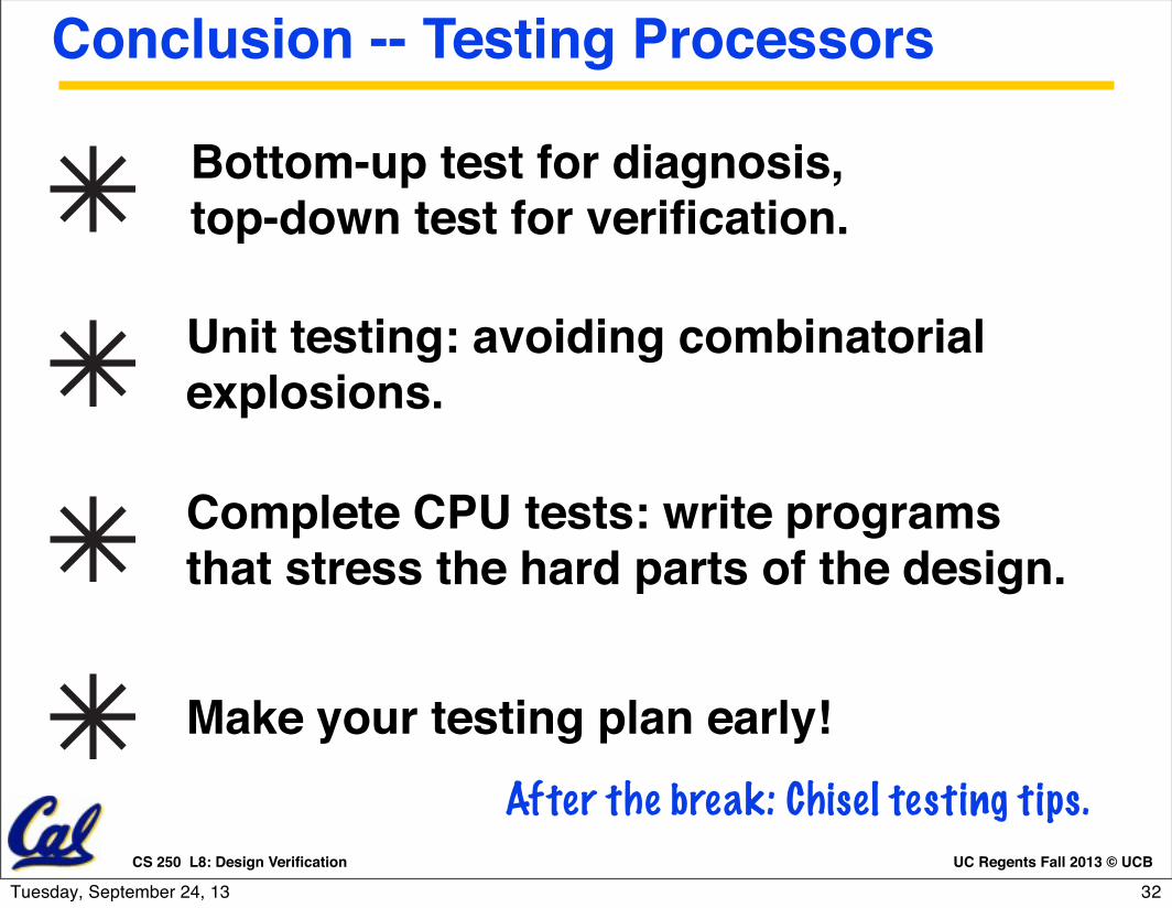
Conclusion -- Testing Processors!
Make your testing plan early!
Unit testing: avoiding combinatorial explosions.
Bottom-up test for diagnosis, top-down test for verification.
Complete CPU tests: write programs that stress the hard parts of the design.
After the break: Chisel testing tips.
32Tuesday, September 24, 13