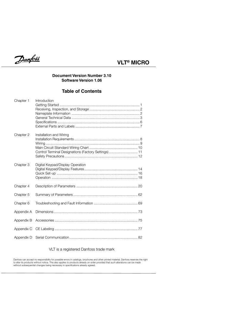
VLT ® MICRO Danfoss can accept no responsibility for possible errors in catalogs, brochures and other printed material. Danfoss reserves the right to alter its products without notice. This also applies to products already on order provided that such alterations can be made without subsequential changes being necessary in specifications already agreed. Table of Contents Chapter 1 Introduction Getting Started ................................................................................. 1 Receiving, Inspection, and Storage ................................................... 2 Nameplate Information ..................................................................... 2 General Technical Data ..................................................................... 3 Specifications ................................................................................... 6 External Parts and Labels ................................................................. 7 Chapter 2 Installation and Wiring Installation Requirements .................................................................. 8 Wiring ............................................................................................... 9 Main Circuit Standard Wiring Chart ................................................. 10 Control Terminal Designations (Factory Settings) ............................. 11 Safety Precautions .......................................................................... 12 Chapter 3 Digital Keypad/Display Operation Digital Keypad/Display Features ...................................................... 14 Quick Set-up .................................................................................. 16 Operation ....................................................................................... 18 Chapter 4 Description of Parameters .............................................................. 20 Chapter 5 Summary of Parameters ................................................................. 62 Chapter 6 Troubleshooting and Fault Information ............................................ 69 Appendix A Dimensions ..................................................................................... 73 Appendix B Accessories .................................................................................... 75 Appendix C CE Labeling .................................................................................... 77 Appendix D Serial Communication ..................................................................... 82 Document Version Number 3.10 Software Version 1.06 VLT is a registered Danfoss trade mark
Transcript
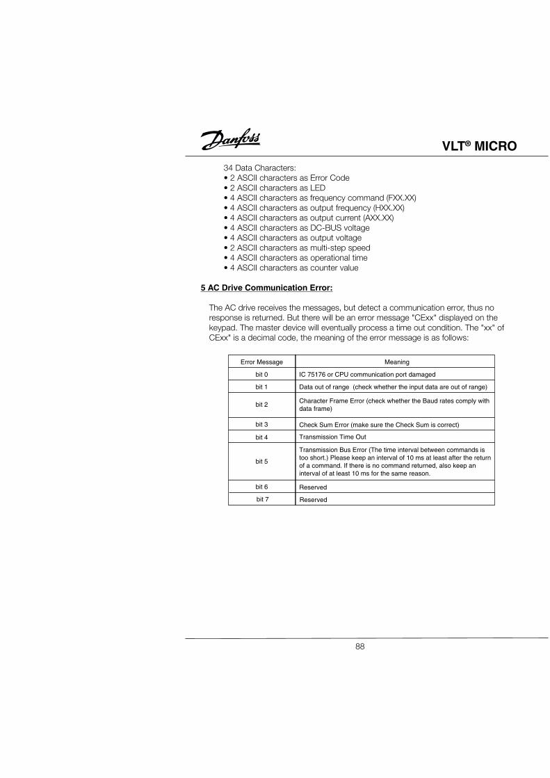
VLT® MICRO
Danfoss can accept no responsibility for possible errors in catalogs, brochures and other printed material. Danfoss reserves the rightto alter its products without notice. This also applies to products already on order provided that such alterations can be madewithout subsequential changes being necessary in specifications already agreed.
Table of Contents
Chapter 1 IntroductionGetting Started ................................................................................. 1Receiving, Inspection, and Storage ................................................... 2Nameplate Information ..................................................................... 2General Technical Data ..................................................................... 3Specifications ................................................................................... 6External Parts and Labels ................................................................. 7
Chapter 3 Digital Keypad/Display OperationDigital Keypad/Display Features ...................................................... 14Quick Set-up .................................................................................. 16Operation ....................................................................................... 18
Chapter 4 Description of Parameters .............................................................. 20
Chapter 5 Summary of Parameters ................................................................. 62
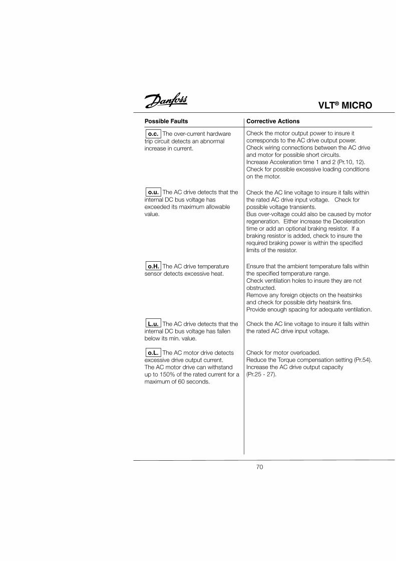
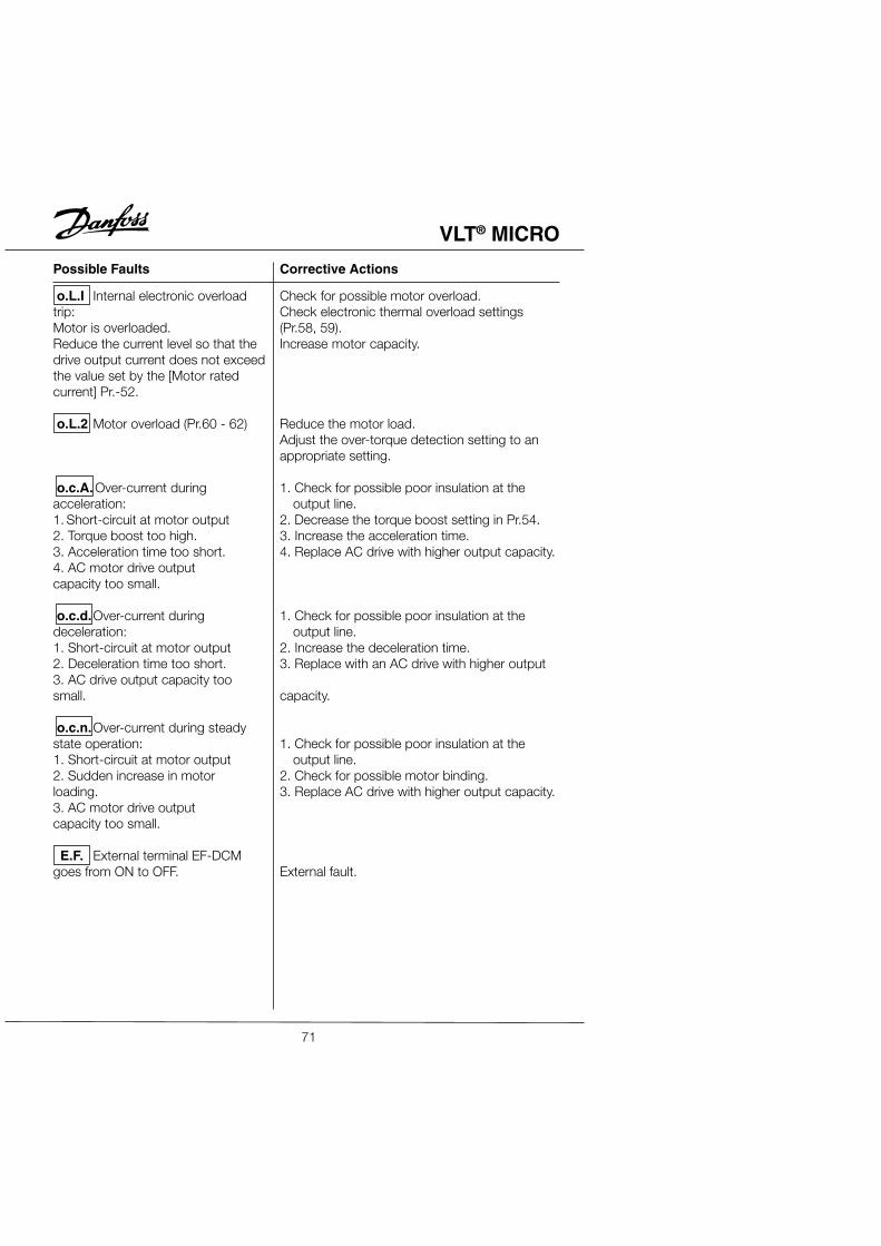
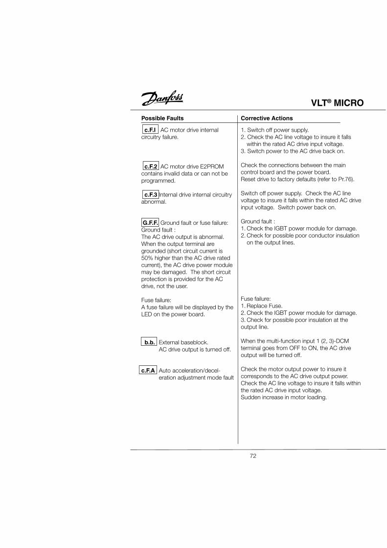
Chapter 6 Troubleshooting and Fault Information ............................................ 69
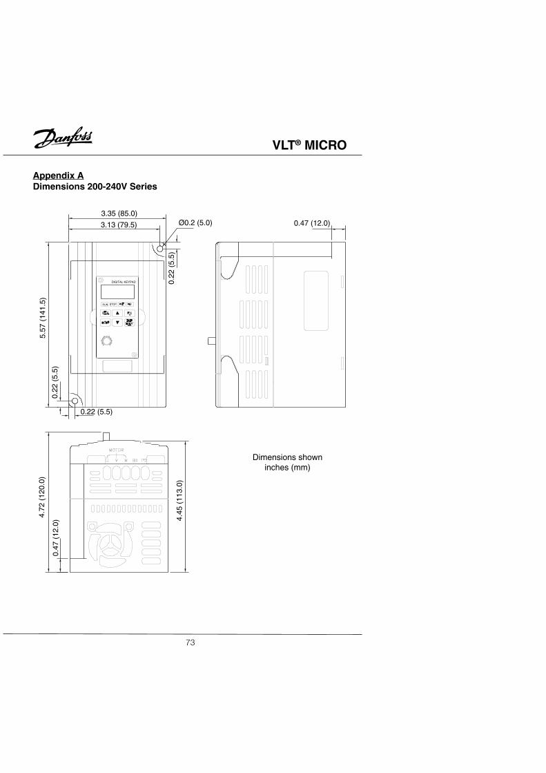
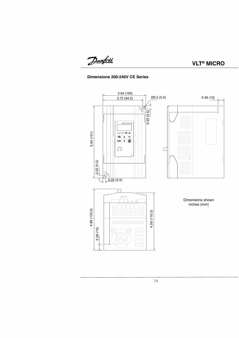
Appendix A Dimensions ..................................................................................... 73
Appendix B Accessories .................................................................................... 75
Appendix C CE Labeling .................................................................................... 77
Appendix D Serial Communication ..................................................................... 82
Document Version Number 3.10Software Version 1.06
VLT is a registered Danfoss trade mark
VLT® MICRO
VLT® MICRO
Chapter 1
IntroductionCongratulations on your purchase of a VLT® Adjustable Frequency Drive. The VLT®
MICRO is a high-performance / low noise general-purpose drive, manufactured usingthe highest quality components and incorporating the latest micro-processor technologyand control algorithms.The purpose of this chapter is to provide specific yet simple information to unpack,install, and operate the drive. This chapter contains information on the following:• Getting Started• Unpacking, Inspection, and Storage• Nameplate Information• Identification of Parts
Getting StartedThis manual will help in the installation, parameter setting, troubleshooting, and dailymaintenance of the AC drive. To guarantee safe operation of the equipment, read thefollowing safety guidelines before connecting the Adjustable Frequency Drive to ACPower.
The VLT Adjustable Frequency Drive (AFD) contains dangerous voltageswhen connected to line voltage. After disconnecting from the line wait atleast one minute before touching any electrical components. Also makesure that other voltage inputs have been disconnected, such as external 24VDC, load-sharing (linkage of DC intermediate circuit), as well as the motorconnection for kinetic back-up. Only a competent electrician should carryout the electrical installation. Improper installation of the motor or the AFDmay cause equipment failure, serious injury or death. Follow this manual,National Electrical Codes (NEC®) and local safety codes.
Electrostatic Precaution; Electrostatic discharge (ESD). Many electroniccomponents are sensitive to static electricity. Voltages so low that theycannot be felt, seen or heard, can reduce the life, affect performance, orcompletely destroy sensitive electronic components. When performingservice, proper ESD equipment should be used to prevent possible damagefrom occurring.
It is the responsibility of the user or the person installing the AFD to provideproper grounding, as well as motor overload and branch circuit protectionaccording to the National Electrical Code (NEC®) and local codes.
WARNING
WARNING
CAUTION
1
VLT® MICRO
Receiving, Transporting, Inspecting, and StorageThis VLT® MICRO Adjustable Frequency Drive has gone through rigorous quality controltests at the factory before shipment. After receiving and before transporting the drive,check for the following.ReceiptAfter receiving the AC drive, inspect the unit to insure it was not damaged duringshipment.TransportationClimatic condition : Class 2K3Inspection• After unpacking the unit, make sure that the package includes a drive unit and theInstruction Manual.• Make sure that the part number indicated on the nameplate and packing carton
corresponds with the part number of your order.StorageThe AFD should be kept in the shipping carton before installation. In order to retain thewarranty coverage, the drive should be stored properly. Some storagerecommendations are:• Store in a clean, dry place• Store within an ambient temperature range of -20°C to +65°C• If possible, store in an air-conditioned evironment where the relative humidity is lessthan 95%, non-condensing.• Do not store the unit in places where it could be exposed to corrosive gases.• Do not store the unit on an unstable surface where it could be damaged by falling tothe floor.Nameplate InformationExample for 1HP 240V AC Adjustable Frequency Drives
Description of Serial Number
1234 01 H 260
Production date:week, year
Place of production
Series number
Serial number
MODEL : 176F7304 S. N. 123401H260INPUT : 3PH 200-240V 50/60 Hz 6.3AOUTPUT : 3PH 0-240V 5.0A 1.9KVA 1HPFreq. Range: 0.1-400Hz
Model, Serial NumberInput Spec.
Output Spec.Freq. Range
Tracking number
Part Numbers:1/2HP 230V single phase 176F73001HP 230V single phase 176F73012HP 230V single phase 176F73021/2HP 230V three phase 176F73031HP 230V three phase 176F73042HP 230V three phase 176F73051/2HP 230V single phase CE 176F73061HP 230V single phase CE 176F73072HP 230V single phase CE 176F7308
2
VLT® MICRO
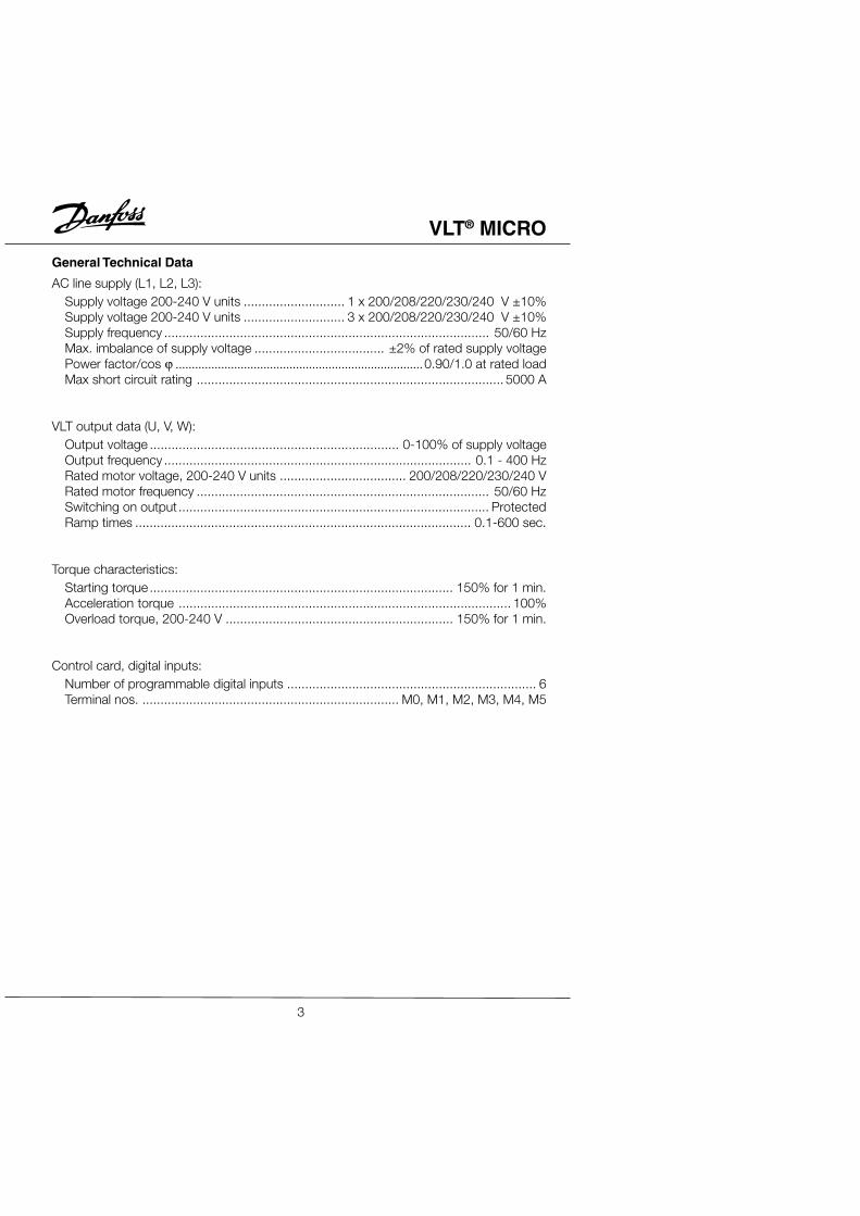
General Technical Data
AC line supply (L1, L2, L3):Supply voltage 200-240 V units ............................ 1 x 200/208/220/230/240 V ±10%Supply voltage 200-240 V units ............................ 3 x 200/208/220/230/240 V ±10%Supply frequency .......................................................................................... 50/60 HzMax. imbalance of supply voltage .................................... ±2% of rated supply voltagePower factor/cos ϕ ............................................................................0.90/1.0 at rated loadMax short circuit rating ..................................................................................... 5000 A
VLT output data (U, V, W):Output voltage ..................................................................... 0-100% of supply voltageOutput frequency ..................................................................................... 0.1 - 400 HzRated motor voltage, 200-240 V units ................................... 200/208/220/230/240 VRated motor frequency ................................................................................. 50/60 HzSwitching on output ...................................................................................... ProtectedRamp times ............................................................................................. 0.1-600 sec.
Torque characteristics:Starting torque .................................................................................... 150% for 1 min.Acceleration torque ............................................................................................ 100%Overload torque, 200-240 V ............................................................... 150% for 1 min.
Control card, digital inputs:Number of programmable digital inputs ..................................................................... 6Terminal nos. ....................................................................... M0, M1, M2, M3, M4, M5
3
VLT® MICRO
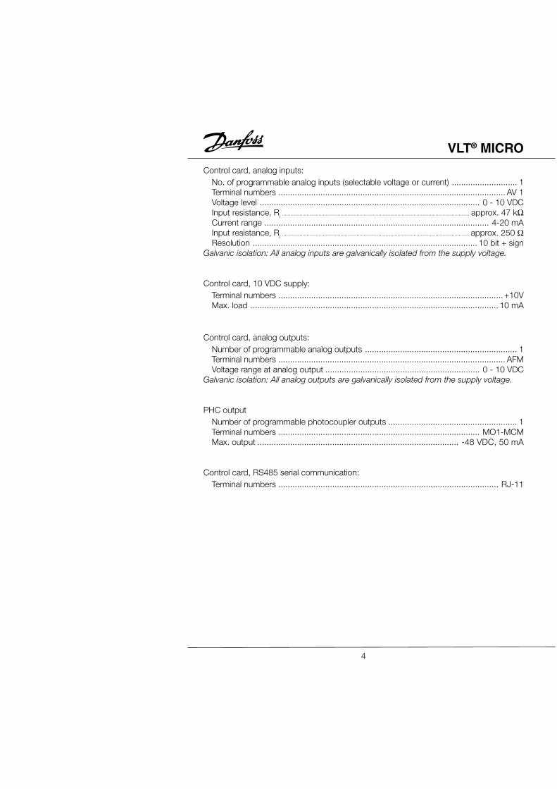
Control card, analog inputs:No. of programmable analog inputs (selectable voltage or current) ............................ 1Terminal numbers ................................................................................................. AV 1Voltage level .............................................................................................. 0 - 10 VDCInput resistance, Ri .......................................................................................................................................... approx. 47 kΩCurrent range ................................................................................................ 4-20 mAInput resistance, Ri .......................................................................................................................................... approx. 250 ΩResolution ................................................................................................ 10 bit + sign
Galvanic isolation: All analog inputs are galvanically isolated from the supply voltage.
Control card, 10 VDC supply:Terminal numbers ................................................................................................ +10VMax. load .......................................................................................................... 10 mA
Control card, analog outputs:Number of programmable analog outputs ................................................................. 1Terminal numbers ................................................................................................. AFMVoltage range at analog output .................................................................. 0 - 10 VDC
Galvanic isolation: All analog outputs are galvanically isolated from the supply voltage.
PHC outputNumber of programmable photocoupler outputs ....................................................... 1Terminal numbers ...................................................................................... MO1-MCMMax. output ...................................................................................... -48 VDC, 50 mA
Control card, RS485 serial communication:Terminal numbers .............................................................................................. RJ-11
Cable lengths and cross-sections:Use 75°C copper wire minimum
Max. motor cable length ...................................................................................... 50 mMax. cable cross-section for line, motor and brake ......................... 14 AWG (2.0 mm2)Max. cable cross-section for control terminals ................................ 14 AWG (2.0 mm2)
Control characteristics:Frequency range ..................................................................................... 0.1 - 400 HzResolution on output frequency .......................................................................±0.1 HzSpeed, control range (open loop) ............................................. 1:20 of synchro. speedSpeed, accuracy (open loop) .............................................< 1800 rpm: max. error 2%......................................................... > 1800 rpm: max. error of 0.5% of actual speed
Environment:Enclosure .............................................................................. Protected chassis (IP20)Vibration test ...................................................... 1.0 g less than 20Hz, 0.6 g 20-50HzMax. relative humidity ................................................ less than 90% (non-condensing)Ambient temperature ............................................................................ –10°C - +50°CTemperature during storage/transport ....................................................... –20 - +60°CMax. altitude above sea level ............................................................ 3300 ft. (1000 m)
VLT® MICRO
6
AC Line 1Ø and 3Ø, 200 - 240 Volt
VLVLVLVLVLT OrT OrT OrT OrT Order Number 1Øder Number 1Øder Number 1Øder Number 1Øder Number 1Ø 176F7300176F7300176F7300176F7300176F7300 176F7301176F7301176F7301176F7301176F7301 176F7302176F7302176F7302176F7302176F73023Ø3Ø3Ø3Ø3Ø 176F7303176F7303176F7303176F7303176F7303 176F7304176F7304176F7304176F7304176F7304 176F7305176F7305176F7305176F7305176F7305
Installation and WiringChapter 2 provides the information needed to properly install and wire the AC motordrive. Make sure that the AC drive is wired according to the instructions contained inthis chapter. The instructions should be read and understood before the actualinstallation begins. This chapter contains the following information:• Installation Requirements• Wiring
Installation RequirementsInstall the drive vertically to provide proper ventilation. Adequate space is requiredbetween the drive and a wall or other equipment. The figure below shows the minimumspace needed.
The AC motor drive should be installed in an environment that is:• protected from rain or moisture• protected from direct sunlight• protected from corrosive gases or liquids• free from airborne dust or metallic particles• free from vibration• free from magnetic noise• Climate condition : Class 3K3 (temperature between -10°C to 50°C, Operation
above 40°C requires good ventilation to avoid over-heating.)
6 in(150mm)
min.
6 in(150mm)
min.
8
VLT® MICRO
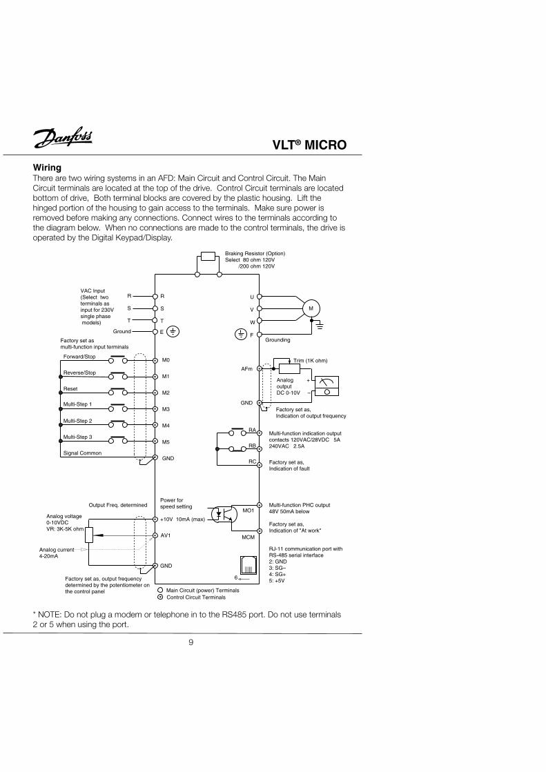
WiringThere are two wiring systems in an AFD: Main Circuit and Control Circuit. The MainCircuit terminals are located at the top of the drive. Control Circuit terminals are locatedbottom of drive, Both terminal blocks are covered by the plastic housing. Lift thehinged portion of the housing to gain access to the terminals. Make sure power isremoved before making any connections. Connect wires to the terminals according tothe diagram below. When no connections are made to the control terminals, the drive isoperated by the Digital Keypad/Display.
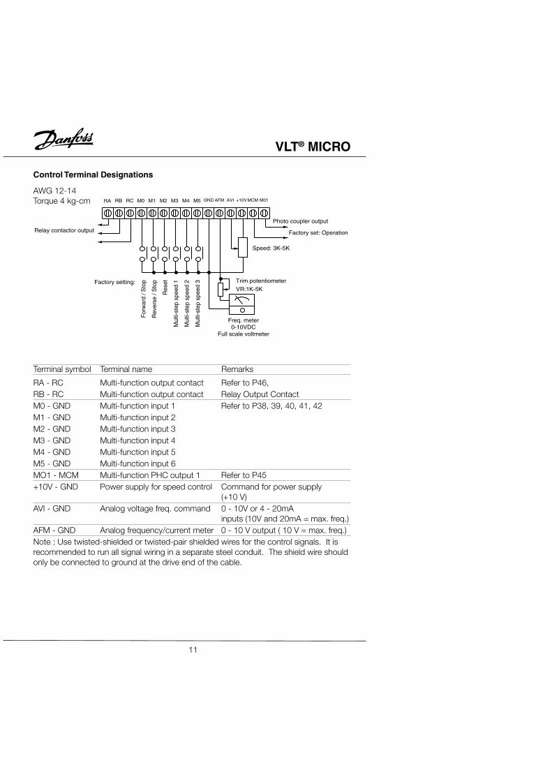
RA - RC Multi-function output contact Refer to P46,RB - RC Multi-function output contact Relay Output ContactM0 - GND Multi-function input 1 Refer to P38, 39, 40, 41, 42M1 - GND Multi-function input 2M2 - GND Multi-function input 3M3 - GND Multi-function input 4M4 - GND Multi-function input 5M5 - GND Multi-function input 6MO1 - MCM Multi-function PHC output 1 Refer to P45+10V - GND Power supply for speed control Command for power supply
(+10 V)AVI - GND Analog voltage freq. command 0 - 10V or 4 - 20mA
inputs (10V and 20mA = max. freq.)AFM - GND Analog frequency/current meter 0 - 10 V output ( 10 V = max. freq.)Note : Use twisted-shielded or twisted-pair shielded wires for the control signals. It isrecommended to run all signal wiring in a separate steel conduit. The shield wire shouldonly be connected to ground at the drive end of the cable.
11
VLT® MICRO
Installation Notes:• Make sure that the appropriate input fusing with specified current ratings are
connected between the AC Power Line and the AC drive. A MCC (contactor withmagnetic trip) is recommended between the drive and circuit breaker to provide ameans to disconnect the drive from the power line in the event of a fault.
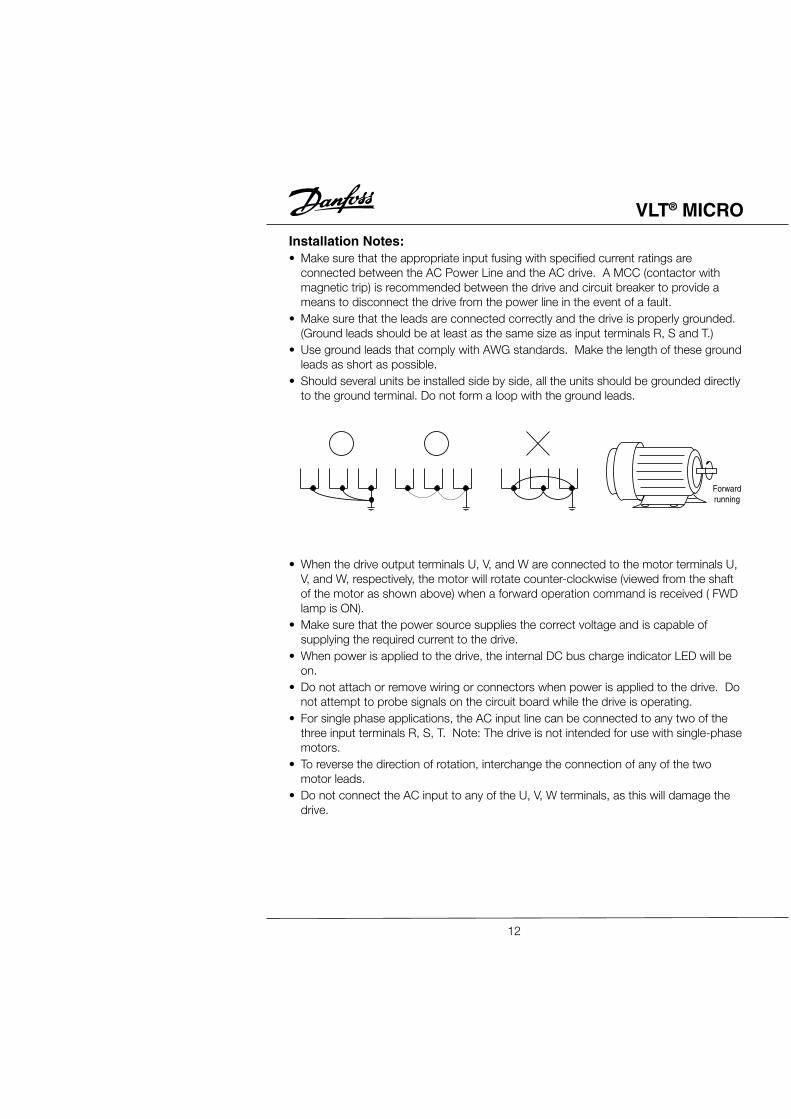
• Make sure that the leads are connected correctly and the drive is properly grounded.(Ground leads should be at least as the same size as input terminals R, S and T.)
• Use ground leads that comply with AWG standards. Make the length of these groundleads as short as possible.
• Should several units be installed side by side, all the units should be grounded directlyto the ground terminal. Do not form a loop with the ground leads.
Forwardrunning
• When the drive output terminals U, V, and W are connected to the motor terminals U,V, and W, respectively, the motor will rotate counter-clockwise (viewed from the shaftof the motor as shown above) when a forward operation command is received ( FWDlamp is ON).
• Make sure that the power source supplies the correct voltage and is capable ofsupplying the required current to the drive.
• When power is applied to the drive, the internal DC bus charge indicator LED will beon.
• Do not attach or remove wiring or connectors when power is applied to the drive. Donot attempt to probe signals on the circuit board while the drive is operating.
• For single phase applications, the AC input line can be connected to any two of thethree input terminals R, S, T. Note: The drive is not intended for use with single-phasemotors.
• To reverse the direction of rotation, interchange the connection of any of the twomotor leads.
• Do not connect the AC input to any of the U, V, W terminals, as this will damage thedrive.
12
VLT® MICRO
• Avoid loose wiring and possible shorts. Tighten all screws on AC circuit terminalssecurely.
• It is a good practice to maintain a 90° angle between wires connected to the ACcircuit terminals and wires connected to the control terminals.
• Use shielded cables for Control Circuit wiring,• Use conduit for the AC power line. The conduit on both the input and output of the
power line should be grounded.• If an EMI filter is required, it should be located close to the drive. Reducing carrier
frequency can also be a way to reduce EMI noise, however audible noise from themotor will increase.
• An L-Filter can be added to the U.V.W. side of AC Motor Drives if needed. Do not usea Capacitor, or L-C Filter (Inductance-Capacitance), or R-C Filter (Resistance-Capacitance).
• A “Ground Fault Interrupt Circuit” can be used. To avoid malfunctioning of the motorand drive, sensitivity of the current sensor should not be less than 200 mA with aresponse time not less than 0.1 second.
13
VLT® MICRO
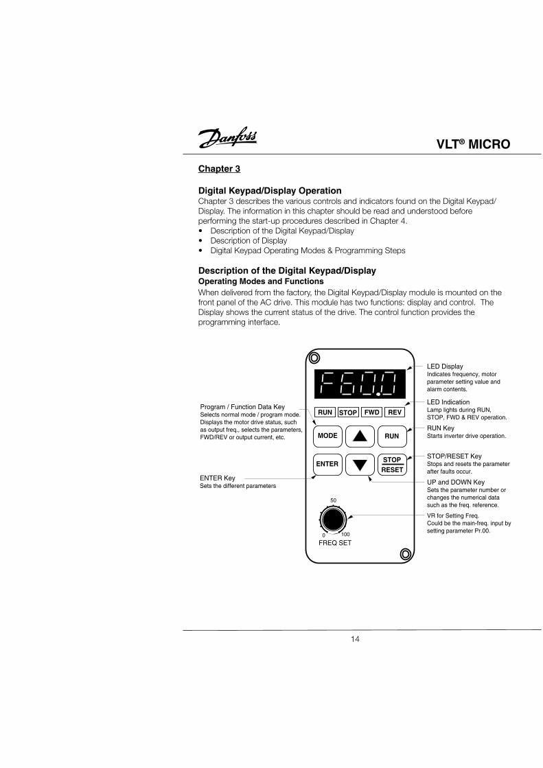
Chapter 3
Digital Keypad/Display OperationChapter 3 describes the various controls and indicators found on the Digital Keypad/Display. The information in this chapter should be read and understood beforeperforming the start-up procedures described in Chapter 4.• Description of the Digital Keypad/Display• Description of Display• Digital Keypad Operating Modes & Programming Steps
Description of the Digital Keypad/DisplayOperating Modes and FunctionsWhen delivered from the factory, the Digital Keypad/Display module is mounted on thefront panel of the AC drive. This module has two functions: display and control. TheDisplay shows the current status of the drive. The control function provides theprogramming interface.
RUN STOP FWD REV
MODE RUN
ENTERSTOPRESET
FREQ SET
50
1000
LED DisplayIndicates frequency, motorparameter setting value andalarm contents.
Program / Function Data KeySelects normal mode / program mode.Displays the motor drive status, suchas output freq., selects the parameters, FWD/REV or output current, etc.
ENTER KeySets the different parameters
LED IndicationLamp lights during RUN,STOP, FWD & REV operation.
RUN KeyStarts inverter drive operation.
STOP/RESET KeyStops and resets the parameter after faults occur.
UP and DOWN KeySets the parameter number or changes the numerical data such as the freq. reference.
VR for Setting Freq.Could be the main-freq. input by setting parameter Pr.00.
14
VLT® MICRO
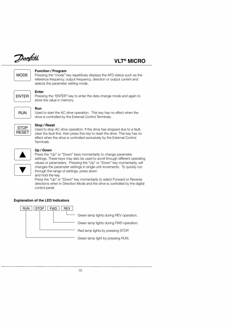
Function / ProgramPressing the “mode” key repetitively displays the AFD status such as thereference frequency, output frequency, direction or output current andselects the parameter setting mode.
EnterPressing the “ENTER” key to enter the data change mode and again tostore the value in memory.
RunUsed to start the AC drive operation. This key has no effect when thedrive is controlled by the External Control Terminals.
Stop / ResetUsed to stop AC drive operation. If the drive has stopped due to a fault,clear the fault first, then press this key to reset the drive. This key has noeffect when the drive is controlled exclusively by the External ControlTerminals.
Up / DownPress the “Up” or “Down” keys momentarily to change parametersettings. These keys may also be used to scroll through different operatingvalues or parameters. Pressing the “Up” or “Down” key momentarily, willchanges the parameter settings in single-unit increments. To quickly runthrough the range of settings, press downand hold the key.Press the "Up" or "Down" key momentarily to select Forward or Reversedirections when in Direction Mode and the drive is controlled by the digitalcontrol panel.
MODE
ENTER
RUN
STOPRESET
RUN STOP FWD REV
Green lamp lights during REV operation.
Green lamp lights during FWD operation.
Red lamp lights by pressing STOP.
Green lamp light by pressing RUN.
Explanation of the LED Indicators
15
VLT® MICRO
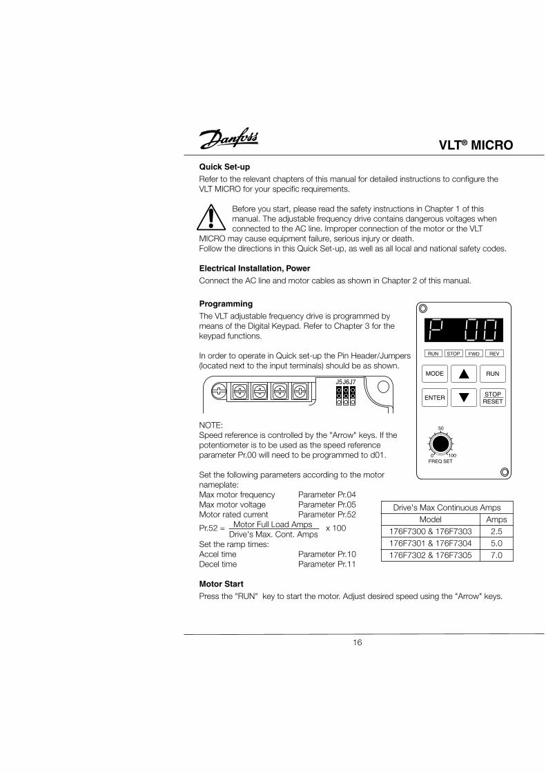
Quick Set-upRefer to the relevant chapters of this manual for detailed instructions to configure theVLT MICRO for your specific requirements.
Before you start, please read the safety instructions in Chapter 1 of thismanual. The adjustable frequency drive contains dangerous voltages whenconnected to the AC line. Improper connection of the motor or the VLT
MICRO may cause equipment failure, serious injury or death.Follow the directions in this Quick Set-up, as well as all local and national safety codes.
Electrical Installation, PowerConnect the AC line and motor cables as shown in Chapter 2 of this manual.
ProgrammingThe VLT adjustable frequency drive is programmed bymeans of the Digital Keypad. Refer to Chapter 3 for thekeypad functions.
In order to operate in Quick set-up the Pin Header/Jumpers(located next to the input terminals) should be as shown.
NOTE:Speed reference is controlled by the "Arrow" keys. If thepotentiometer is to be used as the speed referenceparameter Pr.00 will need to be programmed to d01.
Set the following parameters according to the motornameplate:Max motor frequency Parameter Pr.04Max motor voltage Parameter Pr.05Motor rated current Parameter Pr.52 Motor Full Load Amps Drive's Max. Cont. AmpsSet the ramp times:Accel time Parameter Pr.10Decel time Parameter Pr.11
Motor StartPress the "RUN" key to start the motor. Adjust desired speed using the "Arrow" keys.
Displays the AC drives output frequency. The frequency may bedetermined by any one of the frequency sources that is selected bythe [Master frequency setting] or [Jog Frequency] command. It mayalso be set using the [Multi-step speed setting 1 - 7] as determined bythe inputs to Multi-function Input terminals 1, 2 and 3.If the frequency source originates from the control panel, the usercan use either the "up" or "down" key to select the frequency.
Displays the output frequency present at terminals U, V, and W.Displays the custom unit (v), where v = H x Pr.-65.Displays the internal counter value (C).Note : Refer to Chapter 5, Pr.-45, 46, 64 - 66 for detailed description.
Displays the custom unit (v), where v = H x Pr.-65.
Displays the custom unit (r), where r = H x Pr.-65.
Displays the custom unit (L), where L = H x Pr.-65.
Displays the custom unit (%), where % = H x Pr.-65.
Displays the counter value (c).
Displays the output current present at terminals U, V, and W
Displays the internal PLC process step currently being performed.
Displays the specified parameter.
Displays the actual value stored within the specified parameter.
AC drive forward run status.
AC drive reverse run status.
The display will read “end” (as shown in the display to the left) forapproximately 1 second if an input has been accepted. After aparameter value has been set, the new value is automatically stored inmemory. To modify an entry, use the "up" and "down" keys.
The display will read “Err”, if as input is not accepted, or a parametervalue is selected outside the limit of the parameter.
17
VLT® MICRO
Press keysto select theparameter value.
Press keysto select theparameter number.
RUN STOP FWD REV
MODE
ENTER
RUN
STOPRESET
FREQ SET
50
1000
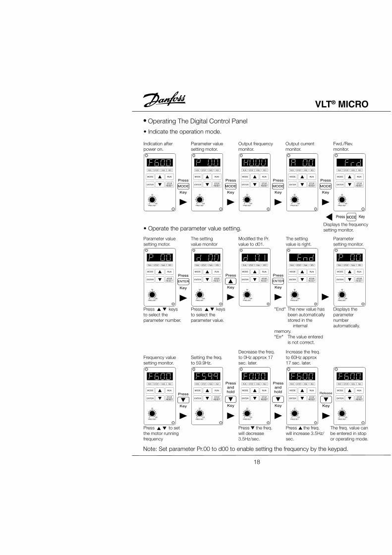
• Operating The Digital Control Panel
RUN STOP FWD REV
MODE
ENTER
RUN
STOPRESET
FREQ SET
50
1000
RUN STOP FWD REV
MODE
ENTER
RUN
STOPRESET
FREQ SET
50
1000
RUN STOP FWD REV
MODE
ENTER
RUN
STOPRESET
FREQ SET
50
1000
RUN STOP FWD REV
MODE
ENTER
RUN
STOPRESET
FREQ SET
50
1000
Press to setthe motor runningfrequency
Note: Set parameter Pr.00 to d00 to enable setting the frequency by the keypad.
RUN STOP FWD REV
MODE
ENTER
RUN
STOPRESET
FREQ SET
50
1000
RUN STOP FWD REV
MODE
ENTER
RUN
STOPRESET
FREQ SET
50
1000
Press the freq.will decrease3.5Hz/sec.
RUN STOP FWD REV
MODE
ENTER
RUN
STOPRESET
FREQ SET
50
1000
Press the freq.will increase 3.5Hz/sec.
RUN STOP FWD REV
MODE
ENTER
RUN
STOPRESET
FREQ SET
50
1000
RUN STOP FWD REV
MODE
ENTER
RUN
STOPRESET
FREQ SET
50
1000
• Operate the parameter value setting.
RUN STOP FWD REV
MODE
ENTER
RUN
STOPRESET
FREQ SET
50
1000
RUN STOP FWD REV
MODE
ENTER
RUN
STOPRESET
FREQ SET
50
1000
RUN STOP FWD REV
MODE
ENTER
RUN
STOPRESET
FREQ SET
50
1000
RUN STOP FWD REV
MODE
ENTER
RUN
STOPRESET
FREQ SET
50
1000
RUN STOP FWD REV
MODE
ENTER
RUN
STOPRESET
FREQ SET
50
1000
Displays theparameternumberautomatically.
Press KeyMODE
MODE
Press
Key
MODE
Press
Key
MODE
Press
Key
MODE
Press
Key
ENTER
Press
Key
Press
Key
ENTER
Press
Key
Press
Key
Press
Key
andhold
Press
Key
andhold Release
Key
• Indicate the operation mode.
Indication afterpower on.
Parameter valuesetting motor.
Output frequencymonitor.
Output currentmonitor.
Fwd./Rev.monitor.
Displays the frequencysetting monitor.
Parameter valuesetting motor.
The settingvalue monitor
Modified the Pr.value to d01.
The settingvalue is right.
Parametersetting monitor.
"End" The new value hasbeen automaticallystored in the
internalmemory."Err" The value entered
is not correct.
Frequency valuesetting monitor.
Setting the freq.to 59.9Hz.
Decrease the freq.to 0Hz approx 17sec. later.
Increase the freq.to 60Hz approx17 sec. later.
The freq. value canbe entered in stopor operating mode.
18
VLT® MICRO
• Change the different indication mode as follows:
RUN STOP FWD REV
MODE
ENTER
RUN
STOPRESET
FREQ SET
50
1000
RUN STOP FWD REV
MODE
ENTER
RUN
STOPRESET
FREQ SET
50
1000
RUN STOP FWD REV
MODE
ENTER
RUN
STOPRESET
FREQ SET
50
1000
RUN STOP FWD REV
MODE
ENTER
RUN
STOPRESET
FREQ SET
50
1000
RUN STOP FWD REV
MODE
ENTER
RUN
STOPRESET
FREQ SET
50
1000
RUN STOP FWD REV
MODE
ENTER
RUN
STOPRESET
FREQ SET
50
1000
RUN STOP FWD REV
MODE
ENTER
RUN
STOPRESET
FREQ SET
50
1000
• Reset the fault messages.
RUN STOP FWD REV
MODE
ENTER
RUN
STOPRESET
FREQ SET
50
1000
RUN STOP FWD REV
MODE
ENTER
RUN
STOPRESET
FREQ SET
50
1000
RUN STOP FWD REV
MODE
ENTER
RUN
STOPRESET
FREQ SET
50
1000
RUN STOP FWD REV
MODE
ENTER
RUN
STOPRESET
FREQ SET
50
1000
RUN STOP FWD REV
MODE
ENTER
RUN
STOPRESET
FREQ SET
50
1000
Press
Key
or
MODE
Press
Key
STOPRESET
Press
Key
Press
Key
RUN MODE
Press
Key
MODE
Press
Key
MODE
Press
Key
After10 sec.
twice
After10 sec.
STOPRESET
Press
Key
Fault messageO.H. is displayed.
Frequency settingwill be displayedafter the fault isremoved.
Change to Reverseoprtation.
Change the Fwd.or Rev. operation.
Setting thefrequency.
Decrease motorspeed to stop. Stop mode.
"STOP" "REV"will light up.
"STOP" "REV" willlight "RUN" willflash.
"STOP" "FWD"will light up.
"RUN" "FWD"will light up.
Indication afterpower on.
Operate at60.0Hz.
Output frequencymonitor.
Output currentmonitor.
Forwardoperationmonitor.
"RUN" "REV" will light "FWD" will flash.
19
VLT® MICRO
Chapter 4
Description of Parameters
Pr.00 Master Frequency Source SelectFactory Setting d00
Units NoneSettings d00 Master frequency determined by keypad digital control.
d01 Master frequency determined by analog signal of DC 0V - +10V,a. Performed by keypad potentiometer. The pin header and jumpercombined as 1 and 3 in the diagram below.b. Performed by external terminal AVI. The pin header and jumpercombined as 2 and 3 in the diagram below.
d02 Master frequency determined by analog signal of DC 4mA - 20mA.Performed by external terminal AVI. The pin header and jumpercombined as 2 and 4 in the diagram below.
Pin Header/Jumper Diagrams:The pin headers and jumpers are located on the upper right corner of the control boardand can be accessed by opening the input terminal cover.
J5: Selects the source of the potentiometer input fromthe External Control Terminal (AVI) or from theDigital Keypad/Display (LC-03P) potentiometer.
J6, J7: This jumper is used to select the DC voltage signalor DC current signal for master frequency control.
Units NoneSettings d00 Operating instructions determined by the Digital Keypad/Display.
d01 Operating instructions determined by the External Control Terminals.Keypad STOP key is effective.
d02 Operating instructions determined by the External Control Terminals.Keypad STOP key is not effective.
(Refer to parameters 38, 39, 40, 41 and 42 for more details.)
Pr.02 Motor Stop Method SelectFactory Setting d00
Units NoneSettings d00 Ramp stop
d01 Coast to stop
This parameter determines how the motor is stopped when the AC drive receives a validstop command.
Ramp: The AC drive output frequency decelerates down to the minimum outputfrequency (Pr.08) in the time specified by Pr.11 or Pr.13, then the output is turned off.
Coast: The AC drive output is turned off immediately and the motor free runs until itcomes to a stop.
Ramp Coast
To determine the best method to stop the motor, the type of load needs to beconsidered.1. In many applications operator safety and material processing can be improved when"Ramp Stop" is selected. The accel./decel. time required will depend on the specificparameters of your application.2. The advantage of using "Coast-to-stop" is the motor will heat less duringfrequent starting and stopping. Applications where "Coast-to-stop" is commonlyused are fans, pumps, blowers, mixing and agitating.
Frequency command
sec. sec.Speed
Stop command Setting value Stop command ?
Speed (Free running to stop)
Frequency commandHzHz
21
VLT® MICRO
Pr.03, Pr.04, Pr.05, Pr.06, Pr.07, Pr.08, Pr.09 – V / F Curve
Pr.03 Maximum Output FrequencyFactory Setting d60.0 Hz
Units 0.1 HzParameter value d50.0 - d400.0 Hz
This parameter determines the maximum AC drive output frequency. Analog inputs (0 -10 V, 4 - 20 mA) are scaled to correspond to the output frequency range.
Pr.04 Motor FrequencyFactory Setting d60.0 Hz
Units 0.1 HzParameter value d10.0 - d400.0 Hz
This value should be set according to rated frequency of the motor as indicated on themotor nameplate.
Pr.05 Motor VoltageFactory Setting d220.0
Units 0.1 VParameter value d2.0 - d255.0
This parameter determines the Maximum Output Voltage of the AC drive. The maximumoutput voltage setting must be smaller than or equal to the rated voltage of the motor asindicated on the motor nameplate.
Pr.06 Mid-point FrequencyFactory Setting d1.50 Hz
Units 0.1 HzParameter value d0.1 - d400.0 Hz
This parameter sets the Midpoint Frequency of the V/F curve. It may be used todetermine the V/F ratio between the Minimum Frequency and the Mid-point Frequency.
Pr.07 Mid-point VoltageFactory Setting d12.0 V
Units 0.1 VParameter value d2.0 - d255.0
This parameter sets the Midpoint Voltage of the V/F curve. It may be used to determinethe V/F ratio between the Minimum Voltage and the Mid-point Voltage.
This parameter programs the Minimum Output Frequency of the AC drive.
Pr.09 Minimum Output VoltageFactory Setting d12.0 V
Units 0.1 VParameter value d2.0 - d50.0 V
This parameter programs the Minimum Output Voltage of the AC drive.
Voltage
Pr.05
Pr.07
Pr.09
Pr.08 Pr.06 Pr.04 Pr.03 Frequency
Fan/Pump V/F CurveCustom V/F Curve
FrequencyPr.03Pr.04Pr.06Pr.08
Pr.05
Pr.07
Pr.09
Voltage
Voltage
Pr.05
Pr.07 Pr.09
Pr.06
Pr.08
Pr.03
Pr.04
Frequency
Standard V/F Curve
0
23
VLT® MICRO
Pr.10, Pr.11, Pr.12, Pr.13 Acceleration / Deceleration Time
Pr.10 Acceleration Time 1 (Can be programmed while the drive is running.)Factory Setting d10.0 Sec
Units 0.1 SecParameter value d0.1 - d600.0 Sec
Commonly Used V/F Pattern Settings
(1) General Purpose
(2) Fans and Pumps
(3) High Starting Torque
Motor Spec 50Hz
Motor Spec 50Hz
Motor Spec 50Hz
Motor Spec 60Hz
Motor Spec 60Hz
Motor Spec 60HzNo. Set value
Pr.03 50.0
Pr.04 50.0
Pr.05 220.0
Pr.06 1.3
Pr.07 12.0
Pr.08 1.3
Pr.09 12.0
No. Set value
Pr.03 60.0
Pr.04 60.0
Pr.05 220.0
Pr.06 3.0
Pr.07 23
Pr.08 1.5
Pr.09 18.0
No. Set value
Pr.03 50.0
Pr.04 50.0
Pr.05 220.0
Pr.06 25
Pr.07 50.0
Pr.08 1.3
Pr.09 10.0
No. Set value
Pr.03 50.0
Pr.04 50.0
Pr.05 220.0
Pr.06 2.2
Pr.07 23.0
Pr.08 1.3
Pr.09 14
Factory Settings
No. Set value
Pr.03 60.0
Pr.04 60.0
Pr.05 220.0
Pr.06 1.5
Pr.07 10.0
Pr.08 1.5
Pr.09 10.0
No. Set value
Pr.03 60.0
Pr.04 60.0
Pr.05 220.0
Pr.06 30
Pr.07 50.0
Pr.08 1.5
Pr.09 10.0
V
220
23
14
1.3 2.2 60.0 f
1.3 25 50.0 f1.5 30 60.0 f
1.5 50.0 f1.5 60.0 f
1.5 3 60.0 f
V
220
50
10
V
220
10
V
220
10
V
220
23
10
V
220
50
10
24
VLT® MICRO
This parameter is used to determine the time required for the AC drive to ramp from 0Hz to its Maximum Output Frequency (Pr.03). The rate is linear unless S Curve is"enabled". This rate of acceleration applies to any incremental increase in commandfrequency unless selected using the Multi-Function Inputs, MI1 - 3. See Parameters 39,40 and 41. Acceleration time 1 is the default when a Multi-Function Input Terminal hasnot been programmed to select between Acceleration time 1 and Acceleration time 2.
Pr.11 Deceleration Time 1 (Can be programmed while the drive is running.)Factory Setting d10.0 Sec
Units 0.1 SecParameter value d0.1 - d600.0 Sec
This parameter is used to determine the time required for the AC drive to deceleratefrom the Maximum Output Frequency (Pr.03) down to 0 Hz. The rate is linear unless SCurve is "enabled". Deceleration time 1 is the default when a Multi-Function InputTerminal has not been programmed to select between Deceleration time 1 andDeceleration time 2.
Note: See Pr.101; Automatic Accel and Decel times are default. Change to "LinearAcceleration/Deceleration" to enable manual adjustment.
Pr.12 Acceleration Time 2 (Can be programmed while the drive is running.)Factory Setting d10.0 Sec
Units 0.1 SecParameter value d0.1 - d600.0 Sec
This parameter determines the time required for the AC drive to ramp from 0 Hz to theMaximum Operating Frequency (Pr.03). The rate is linear unless S Curve is "enabled".The rate of acceleration applies to any incremental increase in command frequencyunless Acceleration Time 1 (Pr.10) is selected. Acceleration Time 1 and 2 may beselected using the Multi-Function Inputs M1 - 3. (See Parameters 39, 40 and 41.)
Speed
TimeDecelTime
AccelTime
Frequency command
Pr.10 or Pr.12 Pr.11 or Pr.13
25
VLT® MICRO
Frequency
S-curve characteristics TimeTime
Time
Pr.14 > d01"S curve Enabled"
Pr.14 = d00"S curve Disabled"
Accel time 1 or 2
Decel time 1 or 2
Note: See Pr.101; Automatic Accel and Decel times are default. Change to "LinearAcceleration/Deceleration" to enable manual adjustment.
Pr.13 Deceleration Time 2 (Can be programmed while the drive is running.)Factory Setting d10.0 Sec
Units 0.1 SecParameter value d0.1 - d600.0 Sec
This parameter determines the time for the AC drive to decelerate from the MaximumOutput Frequency (Pr.03) down to 0 Hz. The rate is linear unless S Curve is "enabled".The rate of deceleration applies to any decrease in command frequency unlessDeceleration Time 1 is selected. Deceleration Time 1 and 2 may be selected using theMulti-Function Inputs M1 - 3. (See Parameters 39, 40 and 41.)
Application Notes:1. The Accel./Decel. Time is defined as the time required to change the outputfrequency from the value of Pr.03 to the value of Pr.08 (Maximum and MinimumOutput Frequencies).2. The Accel./Decel. time can be calculated by using the parameter values of the
following formula: a = [(Pr.10, 11, 12, 13)(Pr.03 Pr.08)](Pr.03 0 Hz).3. The actual Accel./Decel. time should be measured to insure it meets the system
requirements.
Pr.14 S-curveFactory Setting d00 Sec
Units NoneParameter value d00 - d07
This parameter should be programmed during start-up. It is used to provide smoothacceleration and deceleration. S-curves can be selected from 1 to 7. Settings 1 to 7 areadded to the active accel./decel. times to form an adjustable S-curve.
26
VLT® MICRO
Pr.15 Jog Accel. / Decel. Time (Can be programmed while the drive is running.)Factory Setting d1.0 Sec
Units 0.1 SecParameter value d0.1 - d600.0 Sec
This parameter, together with the Jog Frequency (Pr.16), determines the time requiredfor the AC drive to ramp from 0 Hz to the Jog Frequency, or the time required to rampfrom the Jog Frequency to 0 Hz.
Pr.16 Jog Frequency (Can be programmed while the drive is running.)Factory Setting d6.00 Hz
Units 0.1 HzParameter value d0.1 - d400.0 Hz
Jog Frequency can be controlled through a Multi-Function Input Terminal: M1 to M5(See Pr.38 - pr.42). Jog starts from the Minimum Output Frequency (Pr.08) acceleratingto the Jog Frequency (Pr.16) in the time interval set by the Accel./Decel. Time (Pr.15).
Pr.17, Pr.18, Pr.19, Pr.20, Pr.21, Pr.22, Pr.23 – Multi-speed OperationMulti-Step Speeds 1, 2, 3, 4, 5, 6, 7 (Can be programmed while the drive is running.)
Factory Setting d0.00 HzUnits 0.1 Hz
Parameter value d0.1 - d400.0 Hz
Multi-step speed Parameters 17 - 23 in conjunction with Parameters 78, 79, 81 - 87provide multi-step motion control.
Speed
JOG frequency P16
JOG command ON OFF
DecelTime
Pr.15
AccelTime
Pr.15
Time
27
VLT® MICRO
Pr.24 Reverse Run InhibitFactory Setting d00
Units NoneSettings d00 REV run enabled
d01 REV run disabled
This parameter inhibits AC drive operation in the reverse direction.
Units NoneSettings d00 Disable over-voltage stall prevention
d01 Enbable over-voltage stall prevention
During deceleration, the DC bus voltage may exceed the maximum amount allowabledue to motor regeneration. When this function is enabled, the AC drive will cease todecelerate and then maintain a constant output frequency. The drive will only resumedeceleration when the voltage drops below the preset value.
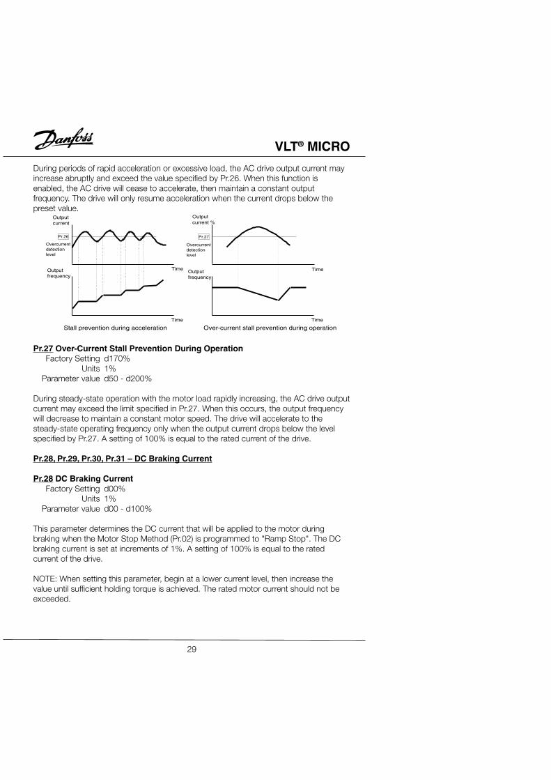
Pr.26, Pr.27 Over-Current Stall Prevention
Pr.26 Over-Current Stall Prevention During AccelerationFactory Setting d170%
Units 1%Parameter value d50 - d200%
Over voltage stall prevention
Time
Time
Outputfrequency
DC busvoltage
Over voltagedetectionlevel
28
VLT® MICRO
During periods of rapid acceleration or excessive load, the AC drive output current mayincrease abruptly and exceed the value specified by Pr.26. When this function isenabled, the AC drive will cease to accelerate, then maintain a constant outputfrequency. The drive will only resume acceleration when the current drops below thepreset value.
Pr.27 Over-Current Stall Prevention During OperationFactory Setting d170%
Units 1%Parameter value d50 - d200%
During steady-state operation with the motor load rapidly increasing, the AC drive outputcurrent may exceed the limit specified in Pr.27. When this occurs, the output frequencywill decrease to maintain a constant motor speed. The drive will accelerate to thesteady-state operating frequency only when the output current drops below the levelspecified by Pr.27. A setting of 100% is equal to the rated current of the drive.
Pr.28, Pr.29, Pr.30, Pr.31 – DC Braking Current
Pr.28 DC Braking CurrentFactory Setting d00%
Units 1%Parameter value d00 - d100%
This parameter determines the DC current that will be applied to the motor duringbraking when the Motor Stop Method (Pr.02) is programmed to "Ramp Stop". The DCbraking current is set at increments of 1%. A setting of 100% is equal to the ratedcurrent of the drive.
NOTE: When setting this parameter, begin at a lower current level, then increase thevalue until sufficient holding torque is achieved. The rated motor current should not beexceeded.
Outputcurrent
Outputcurrent %
Pr.26
Overcurrentdetectionlevel
Outputfrequency
Time
Time
Stall prevention during acceleration Over-current stall prevention during operation
Time
Time
Outputfrequency
Overcurrentdetectionlevel
Pr.27
29
VLT® MICRO
Pr.29 DC Braking Time During Start-upFactory Setting d0.0 Sec
Units 0.1 SecParameter value d0.0 - d5.0 Sec
This parameter determines the time duration that DC braking current will be applied tothe motor during the AC drive start-up.
Pr.30 DC Braking Time During StoppingFactory Setting d0.0 Sec
Units 0.1 SecParameter value d0.0 - d25.0 Sec
This parameter determines the time duration that DC braking current will be applied tothe motor when the Motor Stop Method (Pr.02) is set to "Ramp Stop".
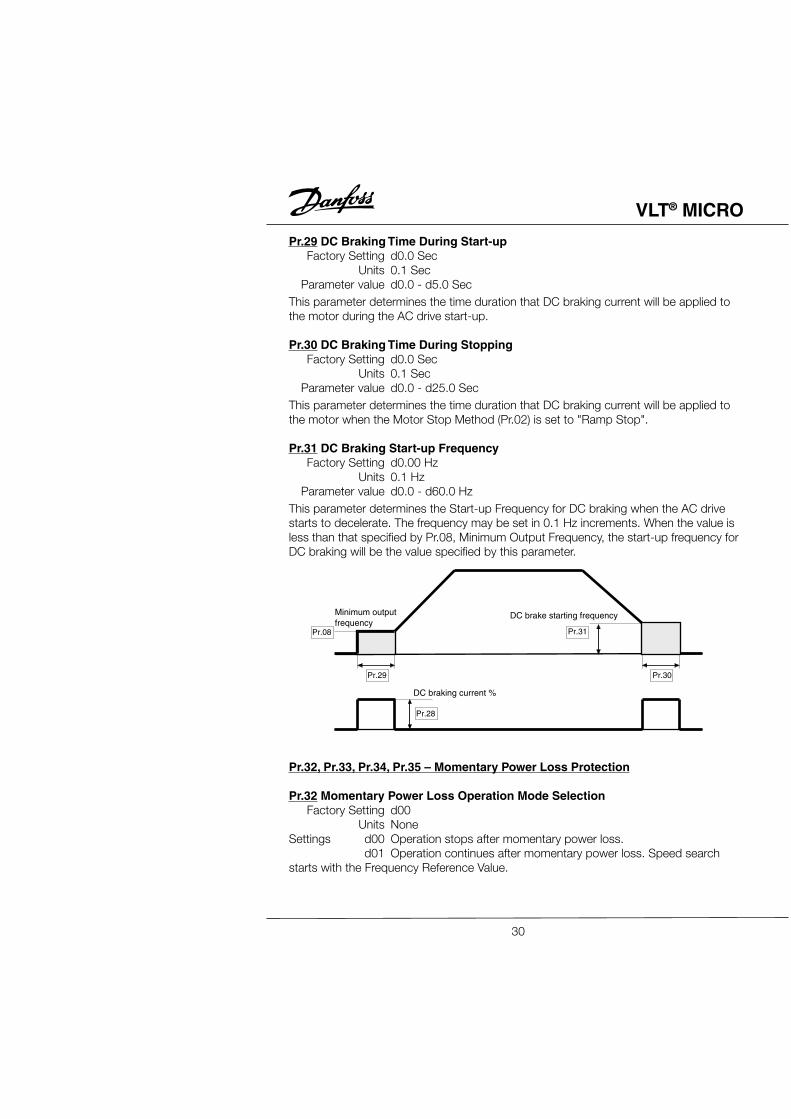
Pr.31 DC Braking Start-up FrequencyFactory Setting d0.00 Hz
Units 0.1 HzParameter value d0.0 - d60.0 Hz
This parameter determines the Start-up Frequency for DC braking when the AC drivestarts to decelerate. The frequency may be set in 0.1 Hz increments. When the value isless than that specified by Pr.08, Minimum Output Frequency, the start-up frequency forDC braking will be the value specified by this parameter.
Pr.32, Pr.33, Pr.34, Pr.35 – Momentary Power Loss Protection
Pr.32 Momentary Power Loss Operation Mode SelectionFactory Setting d00
Units NoneSettings d00 Operation stops after momentary power loss.
d01 Operation continues after momentary power loss. Speed searchstarts with the Frequency Reference Value.
Minimum outputfrequency
DC brake starting frequency
DC braking current %
Pr.08
Pr.29
Pr.28
Pr.31
Pr.30
30
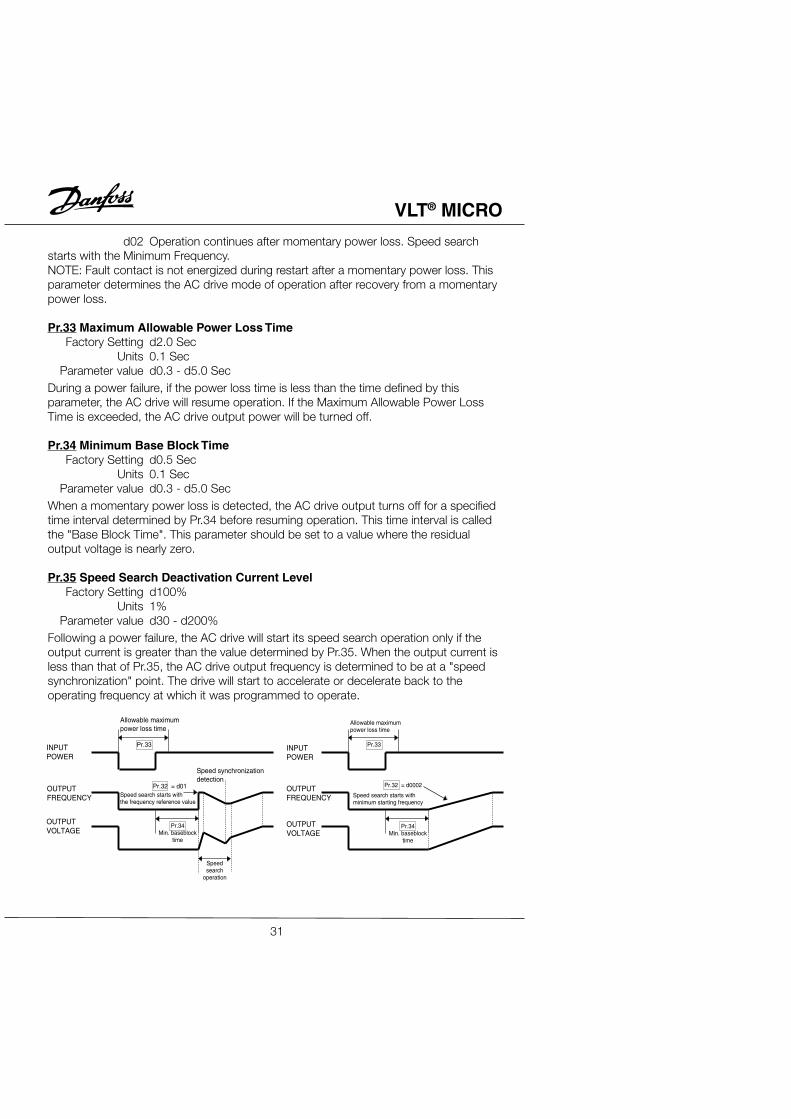
VLT® MICRO
d02 Operation continues after momentary power loss. Speed searchstarts with the Minimum Frequency.NOTE: Fault contact is not energized during restart after a momentary power loss. Thisparameter determines the AC drive mode of operation after recovery from a momentarypower loss.
Pr.33 Maximum Allowable Power Loss TimeFactory Setting d2.0 Sec
Units 0.1 SecParameter value d0.3 - d5.0 Sec
During a power failure, if the power loss time is less than the time defined by thisparameter, the AC drive will resume operation. If the Maximum Allowable Power LossTime is exceeded, the AC drive output power will be turned off.
Pr.34 Minimum Base Block TimeFactory Setting d0.5 Sec
Units 0.1 SecParameter value d0.3 - d5.0 Sec
When a momentary power loss is detected, the AC drive output turns off for a specifiedtime interval determined by Pr.34 before resuming operation. This time interval is calledthe "Base Block Time". This parameter should be set to a value where the residualoutput voltage is nearly zero.
Pr.35 Speed Search Deactivation Current LevelFactory Setting d100%
Units 1%Parameter value d30 - d200%
Following a power failure, the AC drive will start its speed search operation only if theoutput current is greater than the value determined by Pr.35. When the output current isless than that of Pr.35, the AC drive output frequency is determined to be at a "speedsynchronization" point. The drive will start to accelerate or decelerate back to theoperating frequency at which it was programmed to operate.
INPUTPOWER
OUTPUTFREQUENCY
OUTPUTVOLTAGE
Allowable maximumpower loss time
Speed synchronizationdetection
OUTPUTVOLTAGE
OUTPUTFREQUENCY
INPUTPOWER
Pr.33
Pr.32 = d01Speed search starts withthe frequency reference value
Pr.34Min. baseblock
time
Speedsearch
operation
Allowable maximumpower loss time
Pr.33
Pr.32 = d0002
Speed search starts withminimum starting frequency
Pr.36 Reference Frequency Upper LimitFactory Setting d400.0 Hz
Units 0.1 HzParameter Value d0.1 - d400.0 Hz
This parameter programs the upper limit of the reference frequency in 0.1 Hzincrements.
Pr.37 Reference Frequency Lower LimitFactory Setting d0.0 Hz
Units 0.1 HzParameter Value d0.1 - d400.0 Hz
Determines the lower limit of the reference frequency in 0.1 Hz increments.
Application Notes:1. Parameters 36, 37 are provided to prevent damage to the AC motor and applicablemachinery. Under certain conditions a motor can overheat and/or machinery can bedamaged at excessively high speeds.2. The lower limit for AC drive operation is determined by the greater value of Pr.08
(Minimum Output Frequency) and Pr.37 (Reference Frequency Lower Limit). Theupper limit for AC drive operation is determined by the lesser value of Pr.03
(Maximum Output Frequency and Pr.36 Reference Frequency Upper Limit).
d02 3-Wire Operation Control Mode d13 External Base Block (Normally Open)
d03 External Fault (Normally Open) d14 Increase Output Frequency Control
d04 External Fault (Normally Closed) d15 Decrease Output Frequency Control
d05 External Reset d16 Run PLC Program
d06 Multi-Step Speed Control 1 d17 Pause PLC Program
d07 Multi-Step Speed Control 2 d18 Counter Trigger
d08 Multi-Step Speed Control 3 d19 Counter Reset
d09 Jog Frequency d20 No Operation
d10 Accel./Decel. Speed Inhibit Control
33
VLT® MICRO
Explanation:1. d00, d01: Start/Stop/Directional Control – Mode 1 - Two wire control: Parameter value
set to d00 (Pr.38 only).
Mode 2 - Two wire control: Parameter value set to d01 (Pr.38 only).
Mode 3 - Three wire control: Parameter value set to d02 (Pr.38 only).
When value d02 is selected for Pr.38, the program value for Pr.39 will be ignored.Three Wire Control remains in effect.
2. d03, d04: External Fault – Parameter values d03, d04 programs Multi-Function InputTerminals: M1 (Pr.38), M2 (Pr.39), M3 (Pr.40), M4 (Pr.41) or (Pr.42) to be External Fault(E.F.) inputs.
The External Fault input signal has fast priority for display of "E.F." by the DigitalKeypad/Display. All AC drive functions will be stopped and the motor will free-run.Normal operation can resume after the external fault is cleared and the AC drive is reset.
FWD/STOP
REV/STOP
M0 "Open': Stop; "Close": FWD Run
M1 "Open": Stop; "Close": REV Run
GND
VLT MICRO
M0 "Open': Run; "Close": Stop
M1 "Open": FWD; "Close": REV
GND
VLT MICRO
RUN/STOP
REV/FWD
M0 (Run command, Runs when "Closed")
M2 (Stop command, stops when "Open")
M1 (REV/FWD Run select
VLT MICRO
STOP RUN
REV/FWD "Open": FWD Run"Closed": REV Run)GND
Mx "Close": Operation available.
Mx "Open": Operation available.
GND VLT MICRO
Setting by d04
E.F.(N.O)
Setting by d03E.F (N.C)
34
VLT® MICRO
3. d05: External Reset – Parameter value d05 programs a Multi-Function InputTerminal: M1 (Pr.38), M2 (Pr.39), M3 (Pr.40), M4 (Pr.41) or M5 (Pr.42) to be ExternalReset.
External Reset has the same function as the Reset key on the Digital keypad. Externalfaults O.H., O.C. and O.V. are cleared when this input is used to reset the drive.
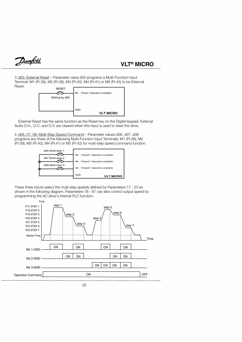
4. d06, 07, 08: Multi-Step Speed Command – Parameter values d06, d07, d08programs any three of the following Multi-Function Input Terminals: M1 (Pr.38), M2(Pr.39), M3 (Pr.40), M4 (Pr.41) or M5 (Pr.42) for multi-step speed command function.
These three inputs select the multi-step speeds defined by Parameters 17 - 23 asshown in the following diagram. Parameters 78 - 87 can also control output speed byprogramming the AC drive's internal PLC function.
Mx "Close": Operation available.
GND
VLT MICRO
RESET
Setting by d05
Mx "Closed": Operation available.
Mx "Closed": Operation available.
Mx "Closed": Operation available.
GND
d06 Multi-step 1
d07 Multi-step 2
d08 Multi-step 3
VLT MICRO
P17 STEP 1
P18 STEP 2
P19 STEP 3
P20 STEP 4
P21 STEP 5
P22 STEP 6
P23 STEP 7
Master Freq.
Freq.
Mx 1-GND
Mx 2-GND
Mx 3-GND
Operation Command ON
ON ON ON ON
ON ON ON ON
ON ON ON ON
OFF
step 2
step 3
step 4
step 5
step 6
step 7
step 1
Time
35
VLT® MICRO
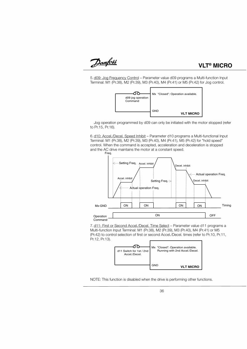
5. d09: Jog Frequency Control – Parameter value d09 programs a Multi-function InputTerminal: M1 (Pr.38), M2 (Pr.39), M3 (Pr.40), M4 (Pr.41) or M5 (Pr.42) for Jog control.
Jog operation programmed by d09 can only be initiated with the motor stopped (referto Pr.15, Pr.16).
6. d10: Accel./Decel. Speed Inhibit – Parameter d10 programs a Multi-functional InputTerminal: M1 (Pr.38), M2 (Pr.39), M3 (Pr.40), M4 (Pr.41), M5 (Pr.42) for "hold speed"control. When the command is accepted, acceleration and deceleration is stoppedand the AC drive maintains the motor at a constant speed.
7. d11: First or Second Accel./Decel. Time Select – Parameter value d11 programs aMulti-function Input Terminal: M1 (Pr.38), M2 (Pr.39), M3 (Pr.40), M4 (Pr.41) or M5(Pr.42) to control selection of first or second Accel./Decel. times (refer to Pr.10, Pr.11,Pr.12, Pr.13).
NOTE: This function is disabled when the drive is performing other functions.
d09 jog operationCommand
Mx "Closed": Operation available.
GNDVLT MICRO
d11 Switch for 1st / 2ndAccel./Decel.
Mx "Closed": Operation available. Running with 2nd Accel./Decel.
GND VLT MICRO
Freq.
Setting Freq,
Mx-GND
OperationCommand
TimingON
ON
ON ON ON
OFF
Actual operation Freq.
Actual operation Freq.
Setting Freq.Accel. inhibit
Accel. inhibit
Decel. inhibit
Decel. inhibit
36
VLT® MICRO
8. d12, d13: External Base Block – Parameter values d12, d13 program Multi-functionalInput Terminals: M1 (Pr.38), M2 (Pr.39), M3 (Pr.40), M4 (Pr.41) or M5 (Pr.42) forexternal Base Block control. Value d12 is for normally open (N.O.) input, and valued13 is for a normally closed input (N.C.).
Application Note:When the programmed inputs for d12 or d13 are used to activate base block control,the motor will free run. When base block control is deactivated, the AC drive will start itsspeed search function and synchronize with the motor speed then accelerated toprogrammed frequency.
INPUTPOWER
OUTPUTFREQUENCY
OUTPUTVOLTAGE
Allowable maximumpower loss time
Pr.33
Pr.32 = d0001
Speed search starts withthe frequency reference value
Min. baseblocktime
Speed searchoperation
Speed synchronizationdetection
Pr.34
B.B. (N.O.)
Setting by d12
B.B. (N.C.)
Setting by d13
Mx "Closed': Operation available.
Mx "Open": Operation available.
GND VLT MICRO
OperationCommand
Mx-GND
ON ON
ON
ON
ON
OFF
Setting Value
Freq.
P10 P11 P12 P13 P10 P13
Time
37
VLT® MICRO
9. d14, d15: Increase/Decrease Output Frequency Control – Parameter value d14programs a Multi-function Input Terminal: M1 (Pr.38), M2 (Pr.39), M3 (Pr.40), M4(Pr.41) or M5 (Pr.42) to incrementally increase the AC drive output frequency by one
unit each time the corresponding input is activated. Parameter value d15 programs aninput to decrease the output frequency.
Application Note:If the Multi-function Input Terminals programmed for Increase/Decrease OutputFrequency Control (d14, d15) are asserted continuously, the output frequency willincrease or decrease unit by unit continuously. If the input is pulsed, the outputfrequency will change one unit. This control function is enabled when the drive isrunning. The modified frequency is stored in non-volitile memory.
10. d16, d17: PLC Function Control – Parameter value d16 programs a Multi-functionInput Terminal: M1 (Pr.38), M2 (Pr.39), M3 (Pr.40), M4 (Pr. 41), M5 (Pr.42) to enable theAC drive internal PLC function. Parameter value d17 programs and input terminal topause the PLC program.
Application Note:Parameter value d16 programs a Multi-function Input Terminal: M1 - M5 to start theinternal PLC program control of the AC drive. Parameters 17 - 23, 78, 79 and 81 to 87define the PLC program. Parameter value d17 programs an input to pause the PLCprogram when the input is shorted to ground. When the input terminal is not closed, thePLC program runs continuously.
UP (N.O.)
Setting by d14
DOWN (N.C.)
Setting by d15Mx "Closed": Operation available Freq. will increase one unit.
GND
Mx "Closed": Operation available Freq. will increase one unit.
VLT MICRO
Mx "Closed": Operation available. Auto-Running is available.
Mx "Closed": Operation available. Auto-Running is available.
GND
AUTO-RUN (N.O.)
Setting by d16
Setting by d17
VLT MICRO
38
VLT® MICRO
12.d18: Counter Trigger – Parameter value d18 programs a Multi-function InputTerminal: M1 (Pr.38), M2 (Pr.39), M3 (Pr.40), M4 (Pr.41) or M5 (Pr.42) to increment theAC drive's internal counter. When the input transitions from low to high the counter isincremented by 1.
Application Note:The Counter Trigger input can be connected to an external sensor to count a processstep or unit of material used in a process. Refer to the diagram below.
13.d19: Counter Reset – Parameter value d19 programs a Multi-function InputTerminal: M1 (Pr.38), M2 (Pr.39), M3 (Pr.40), M4 (Pr.41) or M5 (Pr.42) to reset thecounter.
Application Note:The input terminal resets the counter to "00" which can be displayed on the DigitalKeypad/Display.
GND
Mx Counter value add. one unit by signal "On" to "Off".
Trigger
d18 Counter trigger signal input.
VLT MICRO
Mx "Closed": Operation available. Indicated by c00 on display.
GND
Reset Counter
d19 Reset the counter value.
VLT MICRO
Counter trigger signal
Indication Value(P64)
Multi-function input terminal
Signal output with (P96 = d05)Pr.-96 counter (P45/P46)value is attained.
Signal output with (P97 = d03)Pr.-97 counter (P45/P46)value is attained.
2mS
2mS
The trigger timing can not beless than 2mSec. (<250Hz)
c 02c 03c 02c 01c 00 c 01c 05c 04
39
VLT® MICRO
13.d20: (not used) – Parameter value d20 programs a Multi-function InputTerminal: M1 (Pr.38), M2 (Pr.39), M3 (Pr.40), M4 (Pr.41) or M5 (Pr.42) to provide no
function.
Application Note:The purpose of this function is to provide isolation for unused Multi-function InputTerminals. Any unused terminals should be programmed to d20 to insure they have noeffect on drive operation.
Pr.43 Analog Output to Drive External MeterFactory Setting d00
Units NoneSettings d00 Analog frequency meter (0 to Maximum Frequency, Pr.03)
d01 Analog current meter (0 to 250% of the rated drive output current)This parameter selects the AC drive output frequency or output current that will beproportional to the analog meter output signal voltage (DC: 0v - 10v).
Pr.44 Analog Output Gain (can be programmed while the drive is running)Factory Setting d100%
Units 1%Parameter value d01 - d200%
This function regulates voltage level of the AC motor drives analog signal output (eitherfrequency or current output) at the AFM output terminal, which is then fed to a frequencyor current indication meter.
The analog voltage output is proportional to the ACdrive output frequency. The AC drive's MaximumOutput Frequency (Pr.03) is equivalent to 10 v DC. Ifrequired, adjust the output level using Pr.44, AnalogOutput Gain.
The analog voltage output is proportional to the ACdrive output current. 10 v DC of analog is equivalent to2.5 times the AC drive's Rated Output Current. Ifrequired, adjust the output level using Pr.44, AnalogOutput Gain.
d00 AC drive operational d08 Desired Frequency Attained
d01 Pre-set frequency attained d09 PLC Program Running
d02 Non-zero speed d10 PLC Program Step Completed
d03 Over-torque detection d11 PLC Program Execution Completed
d04 Base Block (B.B.) indicator d12 PLC Program Execution Paused
d05 Low-voltage Detect Indicator d13 Terminal Count Value Reached
d06 AC Drive Control Mode d14 Preliminary Counter Value Reached
d07 Fault Indicator
Explanation:1. d00: AC Drive Operational – The Multi-function Output Terminal contacts will be
"closed" when the AC drive is running or the FWD or REV command is executed.2. d01: Pre-set Frequency Attained – The Multi-function Output Terminal contacts willbe "closed" when the AC drive reaches the specified operating frequency defined byPr.04.3. d02: Zero-speed Indicator – The Multi-function Output Terminal contacts will be
"closed" when the AC drive output frequency is less than the minimum outputfrequency.4. d03: Over-torque Detection Indicator – The Multi-function Output Terminal contactswill remain "closed" as long as over-torque is detected. Parameter Pr.61 programsthe Over-torque Detection Level. Pr.62 sets for the time limitation for over-torquebefore the AC drive output is turned off.5. d04: Base Block Indicator – The Multi-function Output Terminal contacts will alwaysbe "closed" as long as the AC drive output is turned off.6. d05: Low-voltage Detect Indicator – The Multi-function Output Terminal contacts willbe "closed" when the AC drive detects a low-voltage state.
41
VLT® MICRO
7. d06: AC Drive Control Mode – The Multi-function Output Terminal contacts will be"closed" when the AC drive operation is controlled by the external terminals.8. d07: Fault Indicator – The Multi-function Output Terminal contacts will be"closed" when a fault is detected.9. d08: AC Drive Control Mode – The Multi-function Output Terminal contacts will be"closed" when the output frequency equals the Desired Frequency attained (Pr.47).10. d09: PLC Program Running – The Multi-function Output Terminal contacts will be"closed" the PLC program is executing.11. d10: PLC Program Step Completed – The Multi-function Output Terminal contactswill be "closed" within 5 seconds when each multi-step speed is attained.12. d11: PLC Program Completed Execution – The Multi-function Output Terminal
contacts will be "closed" within 5 secs. after the PLC program completes execution.13. d12: PLC Program Execution Paused – The Multi-function Output Terminal contactswill be "closed" when the PLC program execution is paused by a multi-function inputterminal that has been programmed to pause the drive operation.14. d13: Terminal Count Reached – The Multi-function Output Terminal contacts will be"closed" when the counter value is equeal to the value programmed by Pr.96.15. d14: Preliminary Counter Value Reached – The Multi-function Output Terminal
contacts will be "closed" when the counter value equeals the value of Pr.97.
Multi-function terminals wiring example
Pr.47 Desired Frequency AttainedFactory Setting d0.0 Hz
Units 0.1 HzParameter value d0.0 - d400.0 Hz
Used to select a specified frequency in increments of 0.1 Hz.
Multi-Function PHCoutput terminals
Multi-Function indicationoutput terminals
Faults indication
Power indication
RA
RB
RC
MO1
MCM
AC/DC Power Source
AC 250V 2ADC 30V 2A
PHC48VDC 50mA
Plus terminal
Power 48VDC 50mAMinus terminal
BZ
LT
LT
Pre-set freq. attained
42
VLT® MICRO
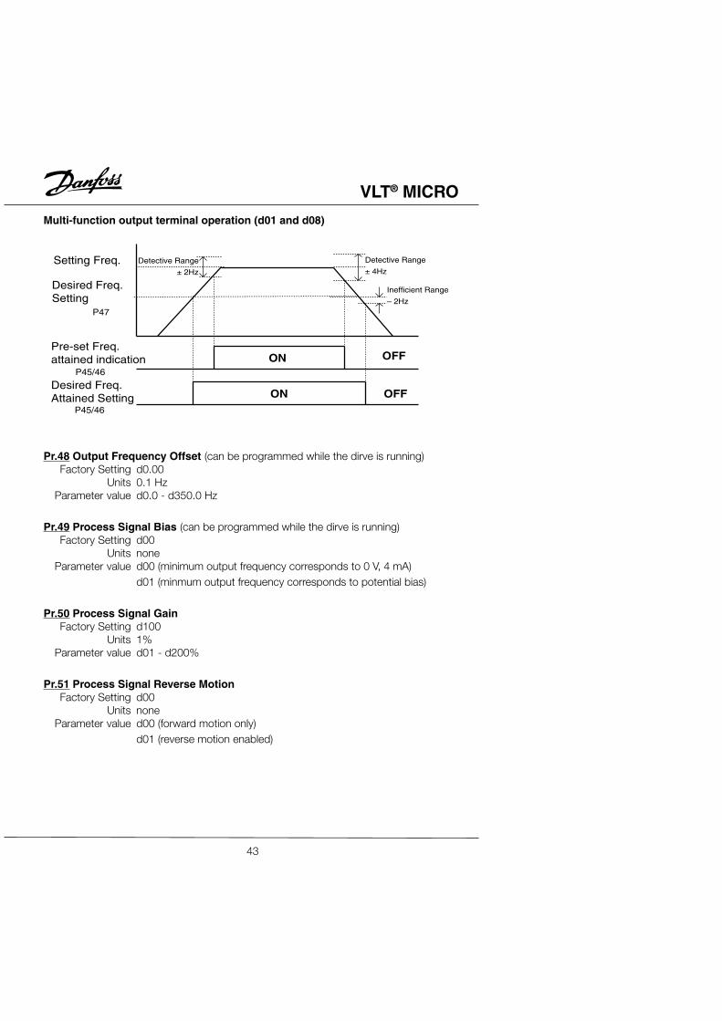
Multi-function output terminal operation (d01 and d08)
Pr.48 Output Frequency Offset (can be programmed while the dirve is running)Factory Setting d0.00
Units 0.1 HzParameter value d0.0 - d350.0 Hz
Pr.49 Process Signal Bias (can be programmed while the dirve is running)Factory Setting d00
Units noneParameter value d00 (minimum output frequency corresponds to 0 V, 4 mA)
d01 (minmum output frequency corresponds to potential bias)
Pr.50 Process Signal GainFactory Setting d100
Units 1%Parameter value d01 - d200%
Pr.51 Process Signal Reverse MotionFactory Setting d00
Units noneParameter value d00 (forward motion only)
d01 (reverse motion enabled)
Detective Range
± 2Hz
ON
ON
OFF
OFF
Setting Freq.
Desired Freq.Setting
Pre-set Freq.attained indication
Desired Freq.Attained Setting
P47
P45/46
P45/46
Detective Range
± 4Hz
Inefficient Range
– 2Hz
43
VLT® MICRO
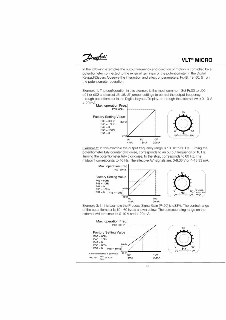
In the following examples the output frequency and direction of motion is controlled by apotentiometer connected to the external terminals or the potentiometer in the DigitalKeypad/Display. Observe the interaction and effect of parameters: Pr.48, 49, 50, 51 onthe potentiometer operation.
Example 1: The configuration in this example is the most common. Set Pr.00 to d00,d01 or d02 and select J5, J6, J7 jumper settings to control the output frequency:through potentiometer in the Digital Keypad/Display, or through the external AV1: 0-10 V,4-20 mA.
Example 2: In this example the output frequency range is 10 Hz to 60 Hz. Turning thepotentiometer fully counter clockwise, corresponds to an output frequency of 10 Hz.Turning the potentiometer fully clockwise, to the stop, corresponds to 60 Hz. Themidpoint corresponds to 40 Hz. The effective AVI signals are: 0-8.33 V or 4-13.33 mA.
Example 3: In this example the Process Signal Gain (Pr.50) is d83%. The control rangeof the potentiometer is 10 - 60 hz as shown below. The corresponding range on theexternal AVI terminals is: 0-10 V and 4-20 mA.
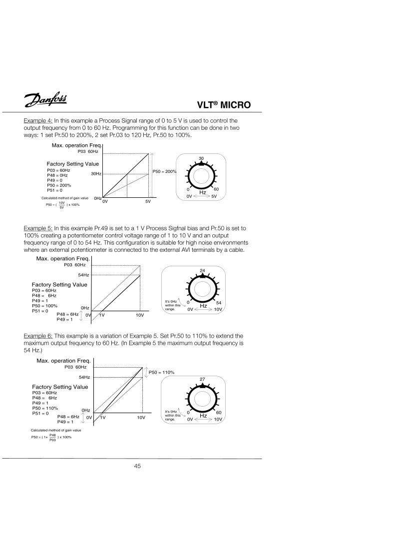
Example 4: In this example a Process Signal range of 0 to 5 V is used to control theoutput frequency from 0 to 60 Hz. Programming for this function can be done in twoways: 1 set Pr.50 to 200%, 2 set Pr.03 to 120 Hz, Pr.50 to 100%.
Example 5: In this example Pr.49 is set to a 1 V Process Sigfnal bias and Pr.50 is set to100% creating a potentiometer control voltage range of 1 to 10 V and an outputfrequency range of 0 to 54 Hz. This configuration is suitable for high noise environmentswhere an external potentiometer is connected to the external AVI terminals by a cable.
Example 6: This example is a variation of Example 5. Set Pr.50 to 110% to extend themaximum output frequency to 60 Hz. (In Example 5 the maximum output frequency is54 Hz.)
Example 7: This example is a combination of the previous 6 examples with forward andreverse motion added. Note: forward and reverse motion control is not available throughthe external terminals. (Refer to Pr.38-42 and Parameter values d00, d01, d02.)
Example 8: In this example sensors are used to control the output frequency from 60 to0 Hz. As the process signal increases from 4 to 20 mA, the output frequency decreasesfrom 60 to 0 Hz.
Pr.52, Pr.53 – Motor Operating Specifications
Pr.52 Motor Rated Current (can be programmed while drive is running)Factory Setting d100%
Units 1%Parameter value d30 - d120%
This parameter must be set according to the ampere specification found on the motornameplate. The setting will limit the AC drive output current and prevent the motor fromoverheating. In the event the motor current exceeds this value, the output frequency willbe reduced until the motor current drops below this limit.
Pr.53 Motor No-load Current (can be programmed while drive is running)Factory Setting d40
Units 1%Parameter value d00 - d99%
Determines the Motor No-load Current in 1% increments. The Motor Rated Current(Pr.52) is set to 100%.
Pr.54 Torque Compensations (can be programmed while drive is running)Factory Setting d02
Units 1%Parameter value d00 - d10%
This parameter may be set so that the AC drive will increase its voltage output duringstart-up to obtain a higher initial starting torque. The additional torque will be presentuntil the maximum operating frequency is attained.
CAUTION: Be careful when selecting the value for Pr.54. If the value is too high, themotor might overheat or be damaged.
Pr.55 Slip Compensation (can be programmed while drive is running)Factory Setting d0.0
Units 0.1 HzParameter value d0.0 - d10.0
As motor load increases, the motor slip increases. This parameter may be used tocompensate for the nominal slip within a range of 0.0 - 10.0 Hz. When the outputcurrent of the AC drive is greater than the Motor No-load Current (Pr.53), the AC drivewill adjust its output frequency according to value of Pr.55.
Pr.56 Special Output DisplayFactory Setting d00
Units NoneSettings d00 Display actual motor operation current
d01 Display DC Bus voltageDisplayed DC Bus voltage can be used to be the basis of input voltage, and is read-only.
This parameter programs the output contacts: RA-RC (N.O.) or RB-RC (N.C.) to indicatethe AC drive is operating at maximum rated output current.
47
VLT® MICRO
Pr.58, Pr.59 – Electronic Thermal Overload Relay
Pr.58 De-rating for Output Current vs. TemperatureFactory Setting d02
Units NoneSettings d00 Active with standard motor
d01 Active with special motord02 Inactive
To prevent self-cooled motors from over heating when running at low speeds, programthis parameter to limit the AC drive output power.d00:The electronic thermal characteristics match a reduced torque motor
(standard motor).d01:The electronic thermal characteristics match a constant torque motor
(special motor).
Pr.59 Activation Time for I2t ProtectionFactory Setting d60
Units 1 SecParameter value d30 - d300 Sec
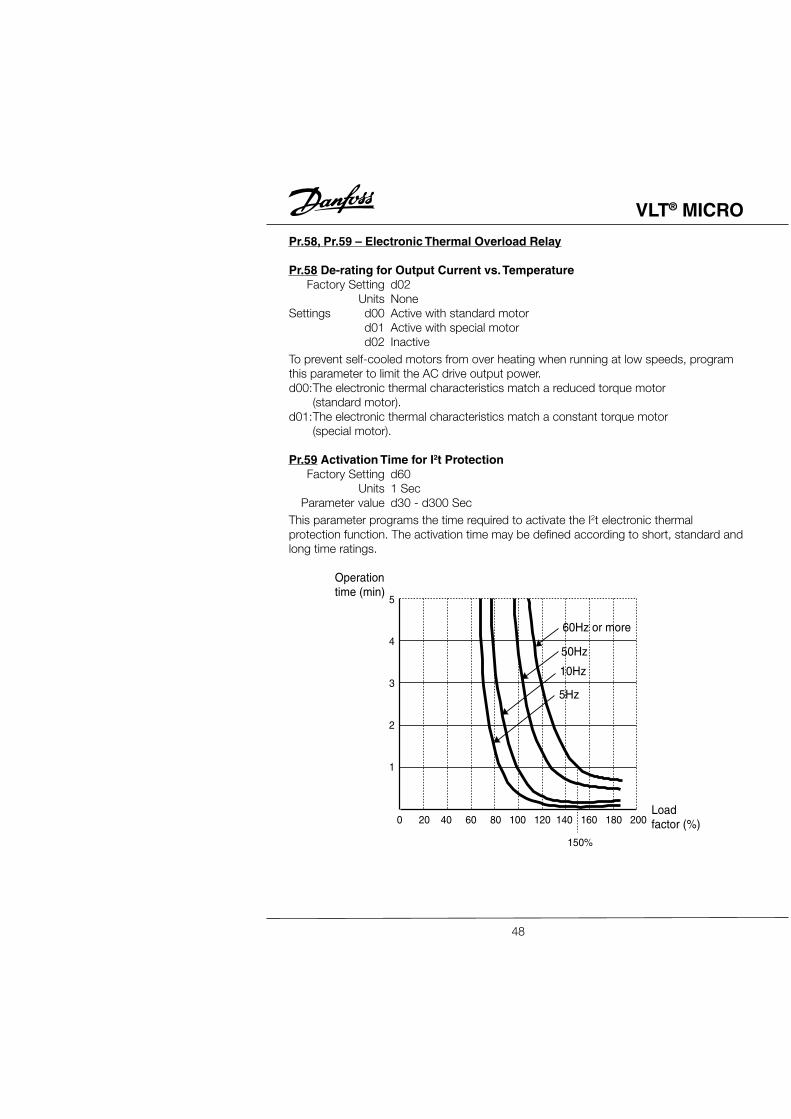
This parameter programs the time required to activate the I2t electronic thermalprotection function. The activation time may be defined according to short, standard andlong time ratings.
Units NoneSettings d00 Over-torque Detection not enabled
d01 Over-torque Detection during constant speed operation.Drive operation halted after over-torque detection.
d02 Over-torque Detection during constant speed operation.Drive operation continues after over-torque detection.
d03 Over-torque Detection during operation.Drive operation halted after over-torque detection.
d04 Over-torque Detection during operation.Drive operation continues after over-torque detection.
This parameter determines the AC drive's operation after Over-torque is detected. Over-torque Detection is based on the following: when the output current exceeds the Over-torque Detection Level (Pr.61, factory preset value = 150%) and the Over-torqueDetection Time (Pr.62, factory setting = 0.1 second = 0.1 second, hysteresis fixed at10%). The Multi-function PHC output 1 and 2 may be set to indicate over-torquecondition. (Refer to Pr.45 and 46).
This parameter sets the Over-torque Detection Time in units of 0.1 seconds.
Pr.63 Reserved
49
VLT® MICRO
Pr.64 User Defined Function for DisplayFactory Setting d06
Units NoneSettings d00 Displays AC drive output frequency (Hz)
d01 Displays the user-defined setting (V, meter/sec where V = H)d02 Displays the user-defined setting (r):(R.P.M.)d03 Displays the user-defined setting (L):(Length)d04 Displays the user-defined setting (=):(%)d05 Displays the value of the internal counter (C)d06 Displays the setting Frequency (F)d07 Displays the parameter setting (P)d08 Reservedd09 Displays the motor operating current (A)d10 Displays Fwd./Rev. mode
The parameter can be set to display the user-defined value. (where V = H x Pr.65)
Pr.65 Coefficient of Line SpeedFactory Setting d160
Units 0.1Parameter value d0.1 - d160
Coefficient K determines the multiplying factor for the user-defined value (v). The value ofthe user-defined setting (v) is calculated and displayed as follows: Display Value, v =output frequency x K. The maximum value that can be displayed is 999. If the value of"v" exceeds "999" the display value defaults to v = output frquency x 0.1.
This parameter determines the three skip frequencies which in conjunction with Pr.70,Skip Frequency Band, will cause the AC motor drives to skip operation at eachfrequency band. Note: Pr.67 > Pr.68 > Pr.69.
50
VLT® MICRO
Pr.70 Frequency Bandwidth Setting PreventionFactory Setting d0.00
Units 0.1 HzParameter value d0.1 - d20.0 Hz
This parameter determines the frequency band for a given Skip Frequency. Half of theSkip Frequency Band is above the Skip Frequency and the other half is below.Programming this parameter to 0.1 disables all skip frequencies.
Pr.71 PWM Carrier Frequency SelectFactory Setting d15
Units 1 kHzParameter value d01 - d18 kHz
This parameter determines the carrier frequency for the "Pulse Width Modulated"output.
Carrier Electromagnetic Noise leakage Heatfrequency noise current dissipation
1kHz large small small3kHz9 kHz15 kHz18 kHz small large large
Note: Audible of AC motor can be reduced by using a higher carrier frequency, howeverplease note that the rated output current of the drive decreases by 0.2A for every 1 kHzincrease in carrier above 16 kHz.
Output frequency
Adjustable range
Speed commandfrequency
Frequency tobe jumped
Skip frequencyset point
Decelerating
Accelerating
0
Pr.67
Pr.68
Pr.69
Pr.70
Pr.70
51
VLT® MICRO
Pr.72 Auto-Reset / Restart Operation Following a FaultFactory Setting d00
Units noneParameter value d00 - d10
Auto-Reset/Restart Operation may be performed up to 10 times after a fault hasoccurred. Setting the parameter to d00 disables the Reset/Restart operation after a faulthas occurred. When the drive detects over current or over voltage the Auto Reset/Restart function can be selected to automatically restart the drive.
Pr.73, Pr.74, Pr.75 – Three Most Recent Fault Records
Pr.73, 74, 75 The 1st, 2nd, 3rd most recent fault recordFactory Setting d00
Units noneSettings d00 Fault records clear (no errors occurred)
d01 Over-current (oc)d02 Over-voltage (ov)d03 Overheat (oH)d04 Overload (oL)d05 Overload 1 (oL1)d06 External Fault (EF)d07 CPU failure 1 (CF1)d08 CPU failure 3 (CF3)d09 Hardware Protection Failure (HPF)d10 Over-current during acceleration (OCA)d11 Over-current during deceleration (OCd)d12 Over-current during steady state operation (OCn)d13 Ground fault or false failure (GFF)d14 Manufacturer-used diagnosticsd15 Manufacturer-used diagnosticsd16 Manufacturer-used diagnosticsd17 External Base Block (bb)d18 Overload 2 (oL2)d19 Manufacturer-used diagnosticsd20 Software protection code
Parameters: Pr.73, Pr.74 and Pr.75 store the three most recent faults that haveoccurred. Set these parameters to d00 to clear the fault and return the drive to service.The fault should be removed before returning the drive to service.
52
VLT® MICRO
Pr.76 Parameter KeyFactory Setting d00
Units NoneSettings d00 All parameters can always be set and read
d01 All parameters are read-onlyd02-d09 Not used
d10 Resets all parameters to the factory defaultsThis parameter controls the programming and read status for all parameters. Value d10resets all parameters to factory settings.
Units NoneSettings d00 Disable PLC program execution
d01 Execute one cycle of the PLC programd02 Continuously execute program cyclesd03 Execute one cycle step by stepd04 Continuously execute program cycles step by step
This parameter controls PLC program execution: Pr.79 - 87.
53
VLT® MICRO
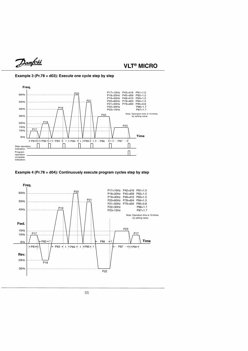
Example 1 (Pr.78 = d01): Execute one cycle through the PLC program
Example 2 (Pr.78 = d02): Continuously execute program cycles
Note: Operation time is 10-times by setting value.
P81
P82
P83 P84 P85
P86
P87
P23
60Hz
50Hz
40Hz
15Hz10Hz
0Hz
P17
P18
P19
P20
P21
P22
Time
Rev.
P81
P17
Freq.
Fwd.
20Hz
30Hz
t
t
ttt
t
t
55
VLT® MICRO
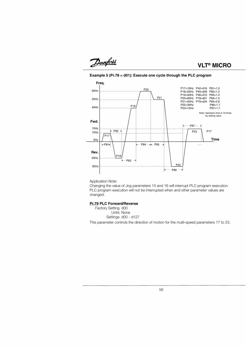
Example 5 (Pr.78 = d01): Execute one cycle through the PLC program
Application Note:Changing the value of Jog parameters 15 and 16 will interrupt PLC program execution.PLC program execution will not be interrupted when and other parameter values arechanged.
Pr.79 PLC Forward/ReverseFactory Setting d00
Units NoneSettings d00 - d127
This parameter controls the direction of motion for the multi-speed parameters 17 to 23.
This parameter contains information on the drive: model number, firmware version, etc.(The parameter is read only).
Pr.81 ~ Pr.87 PLC Program Step Time IntervalsFactory Setting d0.0
Units 10 SecSettings d0.0 - d650
Each of the parameters: 81 to 87 control the time intervals for each Multi-speed Stepdefined by Pr.17 to Pr.23.
Pr.88 ~ Pr.94 Serial Communication (See Appendix D in this manual.)
Pr.95 Auto Energy-savingFactory Setting d00
Units NoneSettings d00 Without energy-saving operation
d01 With energy-saving operationWhile enabling auto energy-saving, the AC motor drive operates at full power duringacceleration/deceleration, and provides the motor optimum voltage calculatedautomatically based on the load power when operating at fixed rotation speed. Thisfunction is not suitable for frequent load variation or load whose operation voltage isclose to its rated load.
Output characteristics curve of energy-saving operation
output voltage
output frequency
base frequency
100%
70%
58
VLT® MICRO
Pr.96 Count Down Completion SettingsFactory Setting d00
Units NoneSettings d00 ~ d999
This parameter defines the terminal count value for the internal counter. The counter canbe incremented by a low-to-high transition on a selected Multi-Function Input Terminal:M1 or M2. Upon completion of the count, if Pr.45 is programmed to d13, the Multi-Function Output Terminal (MO1) will be closed. If Pr.46 is programmed to d13, the Multi-Function Relay Contact RA, RB, RC will be closed.
Pr.97 Preset Count Down Completion SettingsFactory Setting d00
Units NoneSettings d00 ~ d999
This parameter sets a preliminary count value for the internal counter. The counter canbe incremented by a low-to-high transition on one of the programmed Multi-FunctionInput Terminals: M1 or M2. The count starts at c01. When it reaches the preliminarycount value and the selected Multi-Function Output Terminal will be closed (Pr.45 = d14).Preliminary Count can be used to initiate an external event before the "terminal count" isreached. (Se Pr.38, 39, 40, 41, 42, 45, 46 for further details).
Pr.98 ~ Pr.99 Reserved
Pr.100 Software VersionFactory Setting d###
Units NoneSettings None
This parameter shows the software version of the AC motor drive, and is read-only.
59
VLT® MICRO
60
Pr.101 Auto Acceleration/Deceleration Adjustment SelectionFactory Setting d00
Units NoneSettings d00 Linear acceleration deceleration
d01 Automatic acceleration, linear decelerationd02 Linear acceleration, automatic decelerationd03 Automatic acceleration, decelerationd04 For deceleration and stall due to overvoltage
Auto acceleration/deceleration adjustment selection can reduce the mechanical vibrationresulted from run and stop. When acceleration, the AC motor drive can maintain theacceleration current to its rated value, making the motor operate to the set frequency bythe fastest acceleration. When decelerating, it can also judge the load regenerationautomatically, and then stop the motor smoothly in the fastest deceleration time.
Using auto acceleration/deceleration selection can avoid complex regulation procedure.It performs acceleration operation without stall and deceleration stop without brakingresistors. It can also improve operation efficiency effectively and save energy.
This parameter provides five modes from which to choose:d00 Linear acceleration deceleration
(operation at Pr.10, Pr.11 or Pr.12, Pr.13 acceleration/deceleration time)d01 Automatic acceleration, linear deceleration
(operation by automatic acceleration, Pr.11 or Pr.13 deceleration time)d02 Linear acceleration, automatic deceleration
(operation by automatic deceleration time, Pr.10 or Pr.12 acceleration time)d03 Automatic acceleration deceleration
(acceleration/deceleration time is completely decided by AC motor drive automaticcontrol)d04 Linear acceleration/deceleration according to the time setting of parameters Pr.11and Pr.13 auto deceleration.
The auto deceleration function is not suitable when using braking resistors.
Pr.102 Auto Voltage Regulation (AVR)Factory Setting d03
Units NoneSettings d00 Enable auto voltage regulation
d01 Disable auto voltage regulationd02 Disable auto voltage regulation when stopd03 Disable auto voltage regulation when deceleration
VLT® MICRO
61
The rated voltage of motor is normally AC220/200V, 60Hz/50Hz. The input voltage ofAC motor drive can be AC180V~264V, 50Hz/60Hz. Without auto voltage regulation, ifthe input voltage of AC motor drive is AC250V, then the voltage output to the motor isalso AC250V. Under the circumstance that the motor operates with voltage in excess ofrated voltage for 12%~20%, it will cause temperature increase, insulation damage andunstable torque output. In the long run, the life of the motor will be shortened.
The auto voltage regulation of AC motor drive can stabilize the output power to themotor rated voltage automatically when the output power exceeds the motor ratedvoltage. For example, with V/F curve set as AC200V/50Hz, if the input power isAC200V~264V, the voltage output to the motor will be stable at AC200V/50Hz, neverexceeding the set voltage. If the input power varies between AC180V and AC220V, thevoltage output to the motor will proportion to the input power.
When we find the motor stops with ramp type, disabling auto voltage regulation willshorten the deceleration time.
Pr.103 ~ Pr.110 Reserved
Pr.111 Deceleration S curve SettingFactory Setting d00
Units NoneParameter value d00 ~ d7
This parameter can be set to obtain a slow stop without hard braking. The decelerationS curve will differ according to the setting value from 1-7. If there is no specific setting ofthis parameter, the parameter of acceleration/deceleration S curve is determined byparameter Pr.14.
When the parameter setting is d00, then the acceleration/deceleration timing isdetermined by parameter Pr,14 If the parameter setting is between d01 to d07, thenPr.14 is set as acceleration, and Pr.111 is deceleration.
This function can screen and protect external terminals when the CPU mis operates dueto the external disturbance. Factory setting of the scanning time is 2ms. For example:d01; 2ms, d02; 4ms, etc.
It is necessary to change the parameter Pr.77 setting to d02, in order to change thescanning time when setting this parameter.
VLT® MICRO
Chapter 5
Summary of ParametersThis chapter summarizes all 10 of the parameter groups. For complete descriptions ofindividual parameters refer to Chapter 4.
No. Parameter Function Parameter FactoryName Explanation Value Setting
00 Master Speed Master frequency d00:Master frequency input d00Frequency source select determined by the digitalSetting control panel
d01:Master frequency inputdetermined by the analogsignal (DC 0 to +10 V)
d02:Master frequency inputdetermined by the analogsignal (DC 4 to 20 mA)
01 Operation Operation d00:Operating instructions d00Command command determined by the digitalSource source select control panel
d01:Operating instructionsdetermined by the externalterminal connections,keypad STOP key effective
d02:Operating instructionsdetermined by the externalterminal connections, keypadSTOP key not effective
02 Motor stop Motor stop d00:RAMP stop d00method method select d01:Coasting to stop
03 V/F Curve Max output freq. d50.0 - d400. Hz d60.004 Setting Max voltage freq. d10.0 - d400. Hz d60.005 (13 & 14) Max output volt d2.0 - d255.0 V d220.06 Mid-point freq. d0.1 - d400. Hz d1.5007 Mid-point volt d002.0 - d255. V d12.008 Min output freq. d0.1 - d20.0 Hz d1.5009 Min output volt d2.0 - d50.0 V d12.010 Accel/Decel Acceleration time 1 d0.1 - d600. sec d10.011 Time Setting Deceleration time 1 d0.1 - d600. sec d10.012 Acceleration time 2 d0.1 - d600. sec d10.0
62
VLT® MICRO
No. Parameter Function Parameter FactoryName Explanation Value Setting
No. Parameter Function Parameter FactoryName Explanation Value Setting
46 Multi-function d01:Pre-set frequency attained d07RELAY output d02:Non-zero speed
d03:Over-torque detectiond04:Baseblock indicatord05:Low-voltage detectd06:AC drive control moded07:Fault indicatord08:Desired frequency attainedd09:PLC program runningd10:PLC program step completed11:PLC completed executiond12:PLC execution pausedd13:Terminal counter reachedd14:Prelim counter value reached
48 Potentiometer Potentiometer shift d0.0 - d350 Hz d0.0Control of output frequency
49 Potentiometer bias d00:Minimum output frequency d00control corresponds to potentiometer
at 0 V or 4 mAd01:Initial output frequency set
with a potential bias point,refer to Pr.50
50 Potentiometer out- d01 - d200% d100put freq. gain
51 Reverse motion d00:Forward motion only d00setting d01:Reverse motion enabled
52 Mtr. Operating Motor rated current d30 - d120% d100Specifications
53 Motor no-load d00 - d99% d4054 Torque Comp. Auto torque d00 - d10 d02
Setting compensation gain55 Slip Comp. Slip compensation d0.0 - d10.0 d0.056 Specific Output Actual mtr. current d00:Display actual motor current d00
Display or DC Bus voltage d01:Display DC Bus voltage57 AC Drive Rated Current Indicator d##.#58 Electronic Select motor d00:Active with standard motor d02
Thermal derating vs. d01:Active with special motorOverload Relay temperature curves d02:Inactive
65
VLT® MICRO
No. Parameter Function Parameter FactoryName Explanation Value Setting
59 Activation Time for Electronic d30 - d300 sec d60Thermal Protection Function
60 Over-torque Over-torque d00:Over-torque detection not d00Detection detection mode enabled
62 Over-torque d0.1 - d10.0 sec d0.1detection time
63 Reserved64 User Defined Displays user d00:Displays the drive output d06
Parameter defined parameter frequency (H)Displayed on digital keypad/ d01:Display user-define setting (V)
display d02:Display user-define setting (r)d03:Display user-define setting (L)d04:Display user-define setting (%)d05:Display the counter value (c)d06:Display the program freq. (F)d07:Display the par. setting (Pr.00)d08:Reservedd09:Displays motor current (A)d10:Displays Fwd/Rev mode
65 Coefficient K Coefficient for line d0.1 - d160. d1.0speedselect
66
VLT® MICRO
No. Parameter Function Parameter FactoryName Explanation Value Setting
66 Master Freq. d0.1 - 400 Hz d1.067 Frequency Skip frequency 1 d0.0 - d400. Hz d0.068 Setting Skip frequency 2 d0.0 - d400. Hz d0.0069 Prohibited Skip frequency 3 d0.0 - d400. Hz d0.0070 Freq. Band- Skip freq. Band d0.1 - d20.0 Hz d0.00
width SettingPrevention
71 PWM Carrier Carrier frequency d0.1 - d20.0 Hz d0.00Frequency select d01 - d18; fc = 1kHz ~ 18kHz d15
72 Auto Reset/Restart Oper. After Fault d00 - d10 d0073 Fault Records Most recent fault d00: Fault records clear (No d00
record errors occurred)74 2nd most recent d01: Over-current (oc) d00
fault record75 3rd most recent d02: Over-voltage (ov) d00
fault recordd03: Overheat (oH)d04: Overload (oL)d05: Overload 1 (oL1)d06:External fault (EF)d07:CPU failure 1 (CF1)d08: CPU failure 3 (CF3)d09:Hardware protect failure (HPF)d10: O.C. during acceleration (oCA)d11: O.C. during deceleration (ocd)d12: O.C. during steady state (ocn)d13: Ground fault or fuse fail (GFF)d14:EEROM abnormal 2 (CF2)d15: Manufacture used diagnosticsd16: Manufacture used diagnosticsd17: External baseblock (bb)d18: Overload 2 (oL2)d19: Manufacture used diagnosticsd20: Soft protection efficient (codE)
76 Key Key d00: All parameters can always be d00Parameter parameter set and read
d01: All parameters are read-onlyd02 - d09: not usedd10:Resets all parameters to the
factory defaults77 Auto Decel. Auto deceleration d00: Auto deceleration gain key d00
Gain Key gain key d01: Able to adjust the gain value
67
VLT® MICRO
No. Parameter Function Parameter FactoryName Explanation Value Setting
Down Compl. 98-99 Reserved100 Software version Read only d1.06101 Auto Accel/ Auto acceleration/ d00:Linear accel., decel. d00
Decel deceleration d01:Auto accel., linear decel.Adjustment adjustment select d02:Linear accel., auto decel.
d03: Auto accel./decel.102 Auto Voltage Auto voltage d00:Enable auto voltage reg. d03
Regulation regulation d01:Disable auto voltage reg.d02:Disable auto volt reg. w/stopd03:Disable auto volt reg. w/decel
103-110 Reserved111 Decel S-curve d00 ~ d7 d00
Setting112 Ext. Term d00 ~ d20 d00
Scanning timeSetting
68
VLT® MICRO
Chapter 6
TTTTTrrrrroubleshooting and Fault Informationoubleshooting and Fault Informationoubleshooting and Fault Informationoubleshooting and Fault Informationoubleshooting and Fault Information
The AC motor drive has a comprehensive fault diagnosis system that includes more than20 different alarms and fault messages. Once a fault is detected, the correspondingprotective functions will be activated to turn off the AC drive output. The different ACmotor drive failures may be classified as follows:• Over Voltage / Low Voltage• Heatsink Over Temperature• Motor Overload• AC motor drive Overload• Motor Stalled• Microprocessor Systems Failure
The three most recent faults are stored in the AC drive non-volatile memory and may beread through the digital control panel, or through the RS-485 interface on the controlboard.
This section provides information to guide the user in understanding the AC drive faultconditions and the related general troubleshooting procedures. A listing and descriptionof the AC drive failures is given, along with their possible solutions. A section on generaltroubleshooting is also included for reference.Important: Pressing the Reset button will not restore the AC drive to its normaloperating conditions unless the fault is corrected. During any failure, the AC driveswitches off and an error message will appear in the display. The last error that occurredis stored in Pr.73.
69
VLT® MICRO
o.c. The over-current hardwaretrip circuit detects an abnormalincrease in current.
o.u. The AC drive detects that theinternal DC bus voltage hasexceeded its maximum allowablevalue.
o.H. The AC drive temperaturesensor detects excessive heat.
L.u. The AC drive detects that theinternal DC bus voltage has fallenbelow its min. value.
o.L. The AC motor drive detectsexcessive drive output current.The AC motor drive can withstandup to 150% of the rated current for amaximum of 60 seconds.
Possible Faults Corrective Actions
Check the motor output power to insure itcorresponds to the AC drive output power.Check wiring connections between the AC driveand motor for possible short circuits.Increase Acceleration time 1 and 2 (Pr.10, 12).Check for possible excessive loading conditionson the motor.
Check the AC line voltage to insure it falls withinthe rated AC drive input voltage. Check forpossible voltage transients.Bus over-voltage could also be caused by motorregeneration. Either increase the Decelerationtime or add an optional braking resistor. If abraking resistor is added, check to insure therequired braking power is within the specifiedlimits of the resistor.
Ensure that the ambient temperature falls withinthe specified temperature range.Check ventilation holes to insure they are notobstructed.Remove any foreign objects on the heatsinksand check for possible dirty heatsink fins.Provide enough spacing for adequate ventilation.
Check the AC line voltage to insure it falls withinthe rated AC drive input voltage.
Check for motor overloaded.Reduce the Torque compensation setting (Pr.54).Increase the AC drive output capacity(Pr.25 - 27).
70
VLT® MICRO
o.L.I Internal electronic overloadtrip:Motor is overloaded.Reduce the current level so that thedrive output current does not exceedthe value set by the [Motor ratedcurrent] Pr.-52.
o.L.2 Motor overload (Pr.60 - 62)
o.c.A. Over-current duringacceleration:1. Short-circuit at motor output2. Torque boost too high.3. Acceleration time too short.4. AC motor drive outputcapacity too small.
o.c.d.Over-current duringdeceleration:1. Short-circuit at motor output2. Deceleration time too short.3. AC drive output capacity toosmall.
o.c.n.Over-current during steadystate operation:1. Short-circuit at motor output2. Sudden increase in motorloading.3. AC motor drive outputcapacity too small.
E.F. External terminal EF-DCMgoes from ON to OFF.
Check for possible motor overload.Check electronic thermal overload settings(Pr.58, 59).Increase motor capacity.
Reduce the motor load.Adjust the over-torque detection setting to anappropriate setting.
1. Check for possible poor insulation at theoutput line.
2. Decrease the torque boost setting in Pr.54.3. Increase the acceleration time.4. Replace AC drive with higher output capacity.
1. Check for possible poor insulation at theoutput line.
2. Increase the deceleration time.3. Replace with an AC drive with higher output
capacity.
1. Check for possible poor insulation at theoutput line.
2. Check for possible motor binding.3. Replace AC drive with higher output capacity.
External fault.
Possible Faults Corrective Actions
71
VLT® MICRO
c.F.I AC motor drive internalcircuitry failure.
c.F.2 AC motor drive E2PROMcontains invalid data or can not beprogrammed.
c.F.3 Internal drive internal circuitryabnormal.
G.F.F. Ground fault or fuse failure:Ground fault :The AC drive output is abnormal.When the output terminal aregrounded (short circuit current is50% higher than the AC drive ratedcurrent), the AC drive power modulemay be damaged. The short circuitprotection is provided for the ACdrive, not the user.
Fuse failure:A fuse failure will be displayed by theLED on the power board.
b.b. External baseblock.AC drive output is turned off.
c.F.A Auto acceleration/decel-eration adjustment mode fault
Possible Faults Corrective Actions
1. Switch off power supply.2. Check the AC line voltage to insure it falls
within the rated AC drive input voltage.3. Switch power to the AC drive back on.
Check the connections between the maincontrol board and the power board.Reset drive to factory defaults (refer to Pr.76).
Switch off power supply. Check the AC linevoltage to insure it falls within the rated AC driveinput voltage. Switch power back on.
Ground fault :1. Check the IGBT power module for damage.2. Check for possible poor conductor insulation
on the output lines.
Fuse failure:1. Replace Fuse.2. Check the IGBT power module for damage.3. Check for possible poor insulation at theoutput line.
When the multi-function input 1 (2, 3)-DCMterminal goes from OFF to ON, the AC driveoutput will be turned off.
Check the motor output power to insure itcorresponds to the AC drive output power.Check the AC line voltage to insure it falls withinthe rated AC drive input voltage.Sudden increase in motor loading.
72
VLT® MICRO
73
Appendix ADimensions 200-240V Series
0.47
(12
.0)
0.47 (12.0)
0.22
(5.
5)
0.22 (5.5)
Ø0.2 (5.0)
Dimensions showninches (mm)
3.35 (85.0)
3.13 (79.5)
DIGITAL KEYPAD
5.57
(14
1.5)
0.22
(5.
5)
RUN STOP
4.72
(12
0.0)
4.45
(11
3.0)
VLT® MICRO
0.39
(10
)0.39 (10)
0.22
(5.
5)
0.22 (5.5)
Ø0.2 (5.0)
Dimensions showninches (mm)
3.94 (100)
3.72 (94.5)
DIGITAL KEYPAD
5.94
(15
1)
0.22
(5.
5)
RUN STOP
4.86
(12
3.5)
4.59
(11
6.5)
Dimensions 200-240V CE Series
74
VLT® MICRO
Remote Keypad Kit6 ft. (2 meter) 176F731015 ft. (5 meter) 176F7325
Appendix BAccessories
Remote Keypad Kit: 6 ft. (2 meter) 176F731015 ft. (5 meter) 176F7325
DIN Rail Adapter Bracket Kit:200-240V, single and three phase 176F7311200-240V, single phase200-240V single or three phase C 176F7315
DIN Rail Adaptor Bracket Kit :200-240V versions 176F7311200-240V CE versions 176F7315
VLT® MICRO
77
Appendix CCE LabelingWhat is CE Labeling?The purpose of CE labeling is to avoid technical obstacles to trade within EFTA and theEU. The EU has introduced the CE label as a simple way of showing whether a productcomplies with the relevant EU directives. The CE label says nothing about thespecifications or quality of the product. Adjustable frequency drives are regulated bythree EU directives:
The Machinery Directive (89/392/EEC)All machines with critical moving parts are covered by the machinery directive, whichcame into force on 1 January 1995. Since an adjustable frequency drive is largelyelectrical, it does not fall under the machinery directive. However, if an adjustablefrequency drive is supplied for use in a machine, we provide information on safetyaspects relating to the VLT adjustable frequency drive. We do this by means of amanufacturer's declaration.
The Low-voltage Directive (72/23/EEC)Adjustable frequency drives must be CE labelled in accordance with the low-voltagedirective. The directive applies to all electrical equipment and appliances used in thevoltage range of 50-1000 VAC and 75-1500 VDC.
The EMC Directive (89/336/EEC)EMC is short for electromagnetic compatibility. The presence of electromagneticcompatibility means that the mutual interference between different components/appliances is so small that the functioning of the appliances is not affected. The EMCdirective came into force on 1 January 1996. The directive distinguishes betweencomponents, appliances, systems and installations.
What is Covered?The EU "Guidelines on the application of Council Directive 89/336/EEC" outline threetypical situations of using an adjustable frequency drive. For each of these situations,explanations are offered as to whether the situation in question is covered by the EMCdirective and must be CE labelled.1. The adjustable frequency drive is sold directly to the end-consumer. The adjustablefrequency drive is for example sold to a DIY market. The end-consumer is a layman.He installs the adjustable frequency drive himself for use with a hobby machine, akitchen appliance, etc. For such applications, the VLT adjustable frequency drive mustbe CE labeled in accordance with the EMC directive.2. The adjustable frequency drive is sold directly to an installation site. That could be, forexample, a production facility or a heating/ventilation plant designed and installed byprofessionals of the trade. Neither the adjustable frequency drive nor the completedinstallation has to be CE labelled under the EMC directive. However, the unit must
comply with the basic EMC requirements of the directive. The installer can ensure thisby using components, appliances and systems that are CE labeled under the EMCdirective.
VLT® MICRO
78
3. The adjustable frequency drive is sold as part of a complete system. The system isbeing marketed as complete. It could be, for example, an air-conditioning system. Thecomplete system must be CE labeled in accordance with the EMC directive. Themanufacturer who supplies the system can ensure CE labeling under the EMCdirective either by using CE labeled components or by testing the EMC of the system.If he chooses to use only CE labeled components, he does not have to test the entiresystem.
Danfoss VLT Adjustable Frequency Drive and CE LabelingCE labeling is a positive feature when used for its original purpose, i.e. to facilitate tradewithin the EU and EFTA.
However, CE labeling may cover many different specifications. This means that it has tobe checked as to what a given CE label specifically covers.
The specifications covered can in fact be widely different. That is why a CE label cangive the installer a false feeling of security when using an adjustable frequency drive as acomponent in a system or an appliance.
We CE label our VLT adjustable frequency drives in accordance with the low-voltagedirective. This means that as long as the VLT adjustable frequency drive is installedcorrectly, we guarantee that it complies with the low-voltage directive. We issue adeclaration of conformity that confirms our CE labeling in accordance with the lowvoltage directive.
The CE label also applies to the EMC directive, on condition that the instructions given inthe operating instructions for EMC-correct installation and filtering have been followed.On the basis, a declaration of conformity in accordance with the EMC directive is issued.
The operating instructions give detailed instructions for installation to ensure that yourinstallation is EMC-correct. Furthermore, we specify which norms that are complied withby our different products.
We offer the filters that can be seen from the specifications and gladly provide othertypes of assistance that can help you obtain the best EMC result.
Compliance with EMC directive 89/336/EECIn the great majority of cases, the VLT adjustable frequency drive is used byprofessionals of the trade as a complex component forming a larger appliance, systemor installation. It must be noted that the responsibility for the final EMC properties of theappliance, system or installation rests with the installer. As a aid to the installer, Danfosshas prepared EMC installation guidelines for the Power Drive System. The standardsand test levels stated for Power Drive Systems are complied with, provided the rightEMC-correct instructions for installation have been followed.
VLT® MICRO
79
Cs
I4
I3
I2
I1
Z
Z
Z
Z
L1
L2
L3
PE
Cs U
V
W
PE
Line
AdjustableFrequencyDrive Motor Cable Shield Motor
CsGround wire
Shield
Cs
CsCsI4
Ground Plane
General Aspects of EMC EmissionsElectrical interference at frequencies in the range 150 kHz to 30 MHz are cableborne.Airborne interference from the drive system in the range 30 MHz to 1 GHz is generatedfrom the inverter, the motor cable and the motor.As the drawing below shows, capacitive currents in the motor cable together with a highdV/dt from the motor voltage generate leakage currents.The use of a shielded motor cable increases the leakage current (see drawing). This isbecause shielded cables have higher capacitance to ground than unshielded cables. Ifthe leakage current is not filtered, it will cause greater interference on the AC line in theradio frequency range below approximately 5 MHz. Since the leakage current (I1) iscarried back to the unit through the shield (I3), there will in principle only be a smallelectro-magnetic field (I4) from the shielded motor cable according to the drawing below.
The shield reduces the radiated interference, but increases the low-frequencyinterference on the AC line. The motor cable shield must be connected to the VLTenclosure. The best way of doing this is by using integrated shield clamps so as to avoidtwisted shield ends (pigtails). If pigtails are used, make them as short and direct aspossible.
In the cases when the shield is to be placed on a mounting plate for the VLT adjustablefrequency drive, the shield currents are to be conveyed back to the unit. It is alsoimportant to ensure good electrical contact from the mounting plate through themounting screws to the VLT adjustable frequency drive chassis.With respect to installation, it is generally less complicated to use unshielded cablesthan shielded ones.
NOTE: When shielded cables are used some emission requirements are not compliedwith, although the immunity requirements are complied with.
In order to reduce the interference level from the system overall (unit + installation) as faras possible, it is important to make motor and brake cables as short as possible. Cableswith a sensitive signal level must not be alongside motor and brake cables.Radio interference higher than 50 MHz (airborne) will be generated especially by thecontrol electronics.
VLT® MICRO
80
EMC-correct Electrical InstallationGeneral points to be observed to ensure EMC-correct electrical installation:- Use only shielded motor cables and shielded control cables.
NOTE: Suggested shielded cable type, like that supplied by Southwire.- Connect the shield to ground at both ends.- PG Cable Glands, of the type shown below, are recommended. Avoid installation withtwisted shield ends (pigtails), since this ruins the shielding effect at high frequencies.
NOTE: Suggested cable gland, "Jacob PG", supplied by ALTECH.- It is important to ensure good electrical contact from the installation plate through theinstallation screws to the metal cabinet of the VLT adjustable frequency drive.- Use toothed washers and galvanically conductive installation plates.- DO NOT use unshielded motor cables in the installation panels.
The installer is responsible for the final EMC properties and compliance with the LowVoltage Directive for the installation.
Use of EMC-correct cablesShielded/armored cables are recommended to optimize EMC immunity of the controlcables and the EMC emission from the motor cables. The ability of a cable to reduce thein- and outgoing radiation of electric noise depends on the transfer impedance (Z T). Theshield of a cable is normally designed to reduce the transfer of electric noise; however, ashield with a lower Z T value is more effective than a shield with a higher Z T. Z T is rarelystated by cable manufacturers, but it is often possible to estimate Z T by assessing thephysical design of the cable. Z T can be assessed on the basis of the following factors:• The conductibility of the shield material.• The contact resistance between the individual shield conductors.• The shield coverage, i.e. the physical area of the cable covered by the shield - oftenstated as a percentage value.• Shield type, i.e. braided or twisted pattern.
VLT® MICRO
81
10
10
10
1
10
10
10
10
10 5
4
3
2
–1
–2
–3
Transfer impedance, ZmOhm/m
t
0.01 0.1 1 10 100 MHz
Th
e lo
we
r th
e Z
th
e b
ett
er
the
ca
ble
sh
ield
ing
pe
rfo
rma
nce
Aluminum-clad with copper wire.
Twisted copper wire or armored steel wire cable.
Single-layer braided copper wire with varying percentage shield coverage.
Double-layer braided copper wire.
Twin layer of braided copper wire with a magnetic, shielded/armored intermediate layer.
Cable that runs in copper tube or steel tube.
Lead cable with 1.1 mm wall thickness with full coverage.
t
VLT® MICRO
Pr.88 Communication AddressFactory Setting d1
Settings d1 to 254This parameter can be set during operation.
If the AC drive is controlled by RS-485 serial communication, the communicationaddress must be set via this parameter.
This parameter can be set during operation.Users can set parameters and control the operation of the AC drive via the RS-485serial interface of a personal computer. This parameter is used to set the transmissionspeed between the computer and AC drive.
• There is abuilt-in RS-485 serial interface, marked (RJ-11) on the control card. Thepins are defined below:
Each VLT MICRO drive has a pre-assigned communication address specified byPr.88. The computer then controls each AC drive according to its communicationaddress.
• The VLT micro can be setup to communicate on Modbus networks using one of thefollowing modes: ASCII (American Standard Code for Information Interchange).Users can select the desired mode along with the serial port communicationprotocol in Pr.92.
• Code Meaning:ASCII mode:Each 8-bit data is the combination of two ASCII characters. For example, a 1-bytedata: 64 Hex, shown as "64" in ASCII, consists of "6" (36Hex) and "4" (34Hex).
2 Data Format
2.1 10-bit character frame (For 7-bit character):
• (7, N, 2: Pr.92 = 0)
83
VLT® MICRO
Startbit
Stopbit
Evenparity
0 1 2 3 4 5 6
7-bit character10-bit character frame
Startbit
Stopbit
Oddparity
0 1 2 3 4 5 6
7-bit character10-bit character frame
Startbit
Stopbit
Stopbit
0 1 2 3 4 5 6
8-bit character11-bit character frame
7
Startbit
Even parity
Stopbit
0 1 2 3 4 5 6
8-bit character11-bit character frame
7
• (7, E, 1: Pr.92 = 1)
• (7, O, 1: Pr.92 = 2)
• (8, N, 2: Pr.92 = 3)
• (8, E, 1: Pr.92 = 4)
84
VLT® MICRO
Startbit
Odd parity
Stopbit
0 1 2 3 4 5 6
8-bit character11-bit character frame
7
Address CMD02H Data Characters 03H Check Sum
STX ADR1
ADR0
CMD1
CMD0
0 1 N-1...... ETXN CHK1
CHK0
LRC CHK 0
LRC CHK 1
EXT
N
......
DATA (n-1)
DATA 1
DATA 0
CMD 0
CMD 1
ADR 0
ADR 1
STX Start character: (02H)
LRC check sum: 8-bit check sum consists of 2 ASCII codes
End characters:ASCII = 03 Hex
Contents of data: n x 8-bit data consist of 2n ASCII codes n 25 maximum of 50 ASCII codes
Communication address:8-bit address consists of 2 ASCII codes
• (8, O, 1: Pr.92 = 5)
3 Communication Protocol
3.1 Communication Data Frame:
3.2 ASCII mode:
85
VLT® MICRO
3.3 ADR (1, 0)
00: Broadcast to all AC drives ARD1 = 30Hex, ADR0 = 30Hex01: To AC drive at Address 01 ARD1 = 30Hex, ADR0 = 31Hex0F: to AC drive at Address 0F ARD1 = 30Hex, ADR0 = 46Hex10: To AC drive at Address 10 ARD1 = 31Hex, ARD0 = 30HexMaximum is 254, at Address FE
CMD1:Bit 0 = 0 No Mirror TelegramBit 0 = 1 Mirror TelegramBit 2 = 1 When Bit 2 = 1, Means CEXX; clear with RESET command
86
VLT® MICRO
30H"0"
33H"3"
CHK0
CHK1
0 ETX
03H
N1CMD0
38H"8"
30H"0"
CMD1
ADR0
31H"1"
STX
02H 30H"0"
ADR1
N-1......
30H , 34H"0" , "4"
30H"0"
33H"3"
CHK0
CHK1
0 ETX
03H
N1CMD0
38H"8"
30H"0"
CMD1
ADR0
31H"1"
STX
02H 30H"0"
ADR1
N-1......
30H , 34H"0" , "4"
3.5 Data characters
Giving the data format according to the request of communication interface. Forexample, reading address 01 as Pr.04 of AC drive. "0 & 4" are the data format.
3.6 Chk (1,0)
Check Sum is calculated by summing up ADR to ET. For Example, reading address01 as Pr.04 of AC drive.
30H + 31H + 30H + 38H + 30H + 34H + 03H = 130H
4 AC Drive Responding Mode:
4.1 When CMD1 is Mirror Telegram, AC drive will respond to the original command.
4.2 When CMD0 is Read Parameter, AC drive will respond.STX(02H) + ADR(1,0) + CMD(1,0) + 8 Data Characters + EXT + CHK(1,0)
8 Data Characters:• 2 ASCII characters as parameter.• 2 ASCII characters as parameter number.• 4 ASCII characters as parameter setting value.
4.3 When CMD0 is Read Inverter Status, AC drive will respond.STX(02H) + ADR(1,0) + CMD(1,0) + 34 Data Characters + EXT + CHK(1,0)
87
VLT® MICRO
bit 7
bit 6
bit 5
bit 4
bit 3
bit 2
bit 1
bit 0
Error Message
IC 75176 or CPU communication port damaged
Transmission Bus Error (The time interval between commands is too short.) Please keep an interval of 10 ms at least after the return of a command. If there is no command returned, also keep an interval of at least 10 ms for the same reason.
Character Frame Error (check whether the Baud rates comply with data frame)
Data out of range (check whether the input data are out of range)
Meaning
Check Sum Error (make sure the Check Sum is correct)
Transmission Time Out
Reserved
Reserved
34 Data Characters:• 2 ASCII characters as Error Code• 2 ASCII characters as LED• 4 ASCII characters as frequency command (FXX.XX)• 4 ASCII characters as output frequency (HXX.XX)• 4 ASCII characters as output current (AXX.XX)• 4 ASCII characters as DC-BUS voltage• 4 ASCII characters as output voltage• 2 ASCII characters as multi-step speed• 4 ASCII characters as operational time• 4 ASCII characters as counter value
5 AC Drive Communication Error:
The AC drive receives the messages, but detect a communication error, thus noresponse is returned. But there will be an error message "CExx" displayed on thekeypad. The master device will eventually process a time out condition. The "xx" ofCExx" is a decimal code, the meaning of the error message is as follows: