Page 1
RS-232C Reference Version 2.1
1PS
Roland corporation and its affiliates assume no responsibility for any loss or damage (loss of profits,
loss of data or other economical losses) caused by use of this software. This is applicable even in case
users were notified from Roland Corporation and its affiliates about possibility of such losses.
Copyright © 2013 ROLAND CORPORATIONAll rights reserved. No part of this publication may be reproduced in any form without the written permission of ROLAND CORPORATION
Page 3
Contents
Introduction .................................................... 4
Setup................................................................ 5About the RS-232C interface ..................................................................... 5
Connector and cable................................................................................ 5
Handshaking.................................................................................................... 5
Setup procedure ............................................................................................ 6Connection with the control computer ............................................ 6Settings on the control computer....................................................... 6Settings on the V-Mixer........................................................................... 6
Overview of commands.................................. 7Overview of commands .............................................................................. 7
Protocol......................................................................................................... 7Command syntax ...................................................................................... 8Input parameters....................................................................................... 9Output parameters ................................................................................... 9
Cautions during use...................................................................................... 9
Command details.......................................... 10Channel selection parameters ................................................................10
Commands sent from the control computer to the V-Mixer .......10
Details of commands sent from the control computer to the V-Mixer...11
Control commands.................................................................................11PTC: Phantom power supply on/off ...........................................................11PSC: j (phase/polarity) on/off........................................................................12PGC: Preamp gain setting ..............................................................................13FLC: Filter on/off ................................................................................................14EQC: EQ on/off....................................................................................................15GTC: Gate on/off ................................................................................................16CPC: Comp/limiter on/off...............................................................................17AXC: AUX send setting ....................................................................................18MXC: MATRIX send setting ............................................................................19PNC: PAN setting...............................................................................................20MUC: Mute on/off .............................................................................................21FDC: Fader level .................................................................................................22RFC: Relative fader level..................................................................................23SCC: Scene recall ...............................................................................................24RSC: Relative scene recall ...............................................................................24SSC: Scene store ................................................................................................25PIC: Input patchbay setting...........................................................................26POC: Output patchbay setting.....................................................................28LCC: LOCK/UNLOCK the console operation ............................................30BLC: Display blackout/cancel blackout .....................................................31DBC: Display brightness setting ..................................................................31PBC: Panel brightness setting.......................................................................32LBC: Lamp brightness setting.......................................................................32DMC: Monitor dimmer on/off.......................................................................33RTC: USB memory recorder transport .......................................................34RLC: USB memory recorder locate..............................................................34RIC: Song select..................................................................................................35
Request commands................................................................................36CNQ: Channel name request ........................................................................36PTQ: Phantom power supply request........................................................37PSQ: j (phase/polarity) request ....................................................................38PGQ: Preamp gain request ............................................................................39FLQ: Filter request.............................................................................................40EQQ: EQ request ................................................................................................41GTQ: Gate request.............................................................................................42CPQ: Comp/limiter request ...........................................................................43AXQ: AUX send request ..................................................................................44MXQ: MATRIX send request ..........................................................................46PNQ: PAN request .............................................................................................48MUQ: Mute request ..........................................................................................49
FDQ: Fader request .......................................................................................... 50SCQ: Current scene request .......................................................................... 51PIQ: Input patchbay request......................................................................... 52POQ: Output patchbay request................................................................... 54LCQ: Request Locked Status of Console................................................... 56VRQ: Version request....................................................................................... 56RCQ: REAC connection status request ...................................................... 57BLQ: Display blackout status request........................................................ 58DBQ: Display brightness request ................................................................ 58PBQ: Panel brightness request .................................................................... 59LBQ: Lamp brightness request..................................................................... 59DMQ: Monitor dimmer request ................................................................... 60RTQ: USB memory recorder status request............................................. 61RLQ: USB memory recorder current position request......................... 61RIQ: Song number request............................................................................ 62RNQ: Song name request............................................................................... 62RRQ: Recording remain time request........................................................ 63
Commands transmitted from the control computer to the V-Mixer ......................... 64
ack (06H): Active reply .................................................................................... 64ERR: Error.............................................................................................................. 64Xon (11H) / Xoff (13H): Handshaking commands................................. 64
Commands transmitted from the V-Mixer to the control computer ......................... 65
ack (06H): Active reply .................................................................................... 65ERR: Error.............................................................................................................. 65Xon (11H) / Xoff (13H): Handshaking commands................................. 65ERS: Error statuses of the V-Mixer ............................................................... 66EPS: Error statuses of the connected REAC devices ............................. 66
3
Page 4
4
Introduction
This manual explains how you can control the V-Mixer via RS-232C.
This document is written for the following V-Mixer:
• M-480
• M-400
• M-380
• M-300
• M-200i
For details on the V-Mixer itself, please refer to the each V-Mixer’s owner’s manual.
This document assumes that you have a general understanding of computers. For details on computer terminology and
usage, please refer to other documentation.
Please be aware that the contents described in this document are subject to change without notice.
Page 5
Setup
RS-232C is a standard serial interface. An explanation of the connections used by the V-Mixer is given below.
When data is sent from the computer and the V-Mixer’s processing speed is slower than the speed of the incoming data,
something must be done to prevent part of the data from being lost. Conversely, when data is transmitted from the V-Mixer
and the computer’s processing speed is slower than the arriving data, loss of data can occur in the same way.
For this reason, the V-Mixer uses “Xon/Xoff” handshaking. The external computer can control the transmission from the V-
Mixer in the same way.
• “Xon”: This signal is named DC1 (11H) in ASCII code; it is a control code requesting that transmission be started.
• “Xoff”: This signal is named DC3 (13H) in ASCII code; it is a control code requesting that transmission be stopped.
About the RS-232C interface
Connector and cable
Handshaking
7 96 8
1 2 3 54
Connector specifications
Pin number Signal name
1
2
3
4
5
6
7
8
9
NC
RxD (Data In)
TxD (Data Out)
NC
GND
NC
Connected to pin 8
Connected to pin 7
NC
*1: Connected internally within the V-Mixer (pins 7 and 8).
*2: In order for the V-Mixer to operate, the three pins RXD, TXD, and GND must be connected as shown in the diagram.
Cable specifications
RS-232C CABLE *2
V-Mixer COMPUTER
1
2
3
4
5
6
7
8
9
1
2
3
4
5
6
7
8
9
FG
RxD
TxD
GND
*1
5
Page 6
Setup
To set up the V-Mixer and the computer that will control it, proceed as follows:
1. Connect the control computer.
Use a RS-232C cable to connect your computer and the V-Mixer.
☞ “Connection with the control computer” (p. 6).
2. Power up the computer that will be controlling the V-Mixer.
3. Make settings for the control computer
Perform the communication settings.
☞ “Settings on the control computer” (p. 6).
4. Make settings on the V-Mixer.
Perform the communication settings.
☞ “Settings on the V-Mixer” (p. 6).
5. Start operating the V-Mixer.
Control computer —> V-Mixer data transmission will begin.
1. Power off the V-Mixer and the computer.
2. On the rear panel of the V-Mixer, set the RS-232C/MIDI switch to the RS-232C position.
* When you are using M-200i, turn on the power and then select “RS-232C“ under RS-232C/MIDI SELECT paramter.
Refer to the M-200i’s owner’s manual for details.
3. Use an RS-232C cable to connect the RS-232C connector of your computer to the RS-232C connector located on the back of the V-Mixer.
☞ For details on the cable to use, refer to “Connector and cable” (p. 5).
1. Communication settings on the computer
* For details on how to set the communication settings, refer to the owner’s manual of the computer you’re using.
When you power up the V-Mixer, the communication speed will be set to 115200 bps by default. If you’re using the V-Mixer
via RS-232C, you’ll need to set its communication speed to match the setting of the computer.
For details on how to set this, refer to the each V-Mixer’s owner’s manual.
Setup procedure
Connection with the control computer
Settings on the control computer
Communication method Synchronous (asynchronous), full-duplex
Communication speed 4800 / 9600 / 14400 / 31250 / 38400 / 57600 / 115200 bpsYou can select this as desired, but it must be the same as the setting on the V-Mixer.
Parity none
Data length 8 bit
Stop bit 1 bit
Code set ASCII
XonXoff on
Settings on the V-Mixer
6
Page 7
Overview of commands
The V-Mixer and the control computer communicate via commands. There are several types of commands, and you can
control the V-Mixer by using the command that’s appropriate for your purpose.
Single-byte alphanumeric characters are used for commands. In general, the command syntax is an ASCII string consisting of
“stx” and “three uppercase letters” followed by a “;” (semicolon). The three letters indicate the type of command. However,
there are other types depending on the command.
☞ “Command syntax” (p. 8).
* “stx”: This is the name of the signal in ASCII code (code number 02H in hexadecimal); it is a control code that indicates the beginning
of a command.
* “;”: This code lets the V-Mixer detect the end of the command.
<Ex.> To transmit the ** command, transmit the ASCII string “stx**;”
Depending on the command, there are two types of communication protocols between the control computer and the V-
Mixer.
● When specifying an operation or setting for the V-Mixer
This type corresponds to the “Control commands” (p. 11). These commands use the procedure shown in the following diagram.
fig.PrtConcept1.eps
a. Transmit the command from the computer to the V-Mixer.
b The V-Mixer will output “ack” if the command was received correctly, or an ERR command in case of invalid
reception.
* “ack”: This is the ASCII code name of the control code (06H in hexadecimal) acknowledging successful reception.
* Invalid reception corresponds to cases in which the syntax of the received command was incorrect.
* stxERR is the command used to transmit or receive an error indication.
Overview of commands
Protocol
COMPUTER V-Mixera. stx + command
b. ack or stxERR command
7
Page 8
Overview of commands
● To learn the settings of the V-Mixer
This type corresponds to the “Request commands” (p. 36). Commands used to check the status of a setting in the V-Mixer use the following procedure.
fig.PrtConcept2.eps
a. Transmit the command from the computer to the V-Mixer.
b If the V-Mixer receives the command correctly, it will send back a command containing the information that was
requested. If the command was not received correctly, an ERR command will be sent back.
c If the output of the V-Mixer was received correctly, an “ack” will be sent back. (* This “ack” can be omitted.)
* If the ERR command is sent to the V-Mixer, the V-Mixer will re-transmit the command it sent in step “b.” This command can also be
omitted; instead of returning anything, you can repeat the procedure from step “a.”
* The V-Mixer will not transmit anything when a setting is changed by a controller operation on the V-Mixer itself.
There are several possible types of syntax for commands (control signals).
Type 0: Commands consisting only of a control code
“;” is not added to these. They consist only of the control code.
<Ex.> ack
Type 1: Commands that have no parameters
These commands end with “;”.
<Ex.> stxVRQ;
Type 2: Commands that have parameters
Command: parameter, parameter...;
• The command is separated from the parameters by a “:” (colon).
• Parameters are separated by a “,” (comma).
• The end of the parameters is indicated by a “;” (semicolon).
* No spaces or tabs are allowed between commands or parameters.
Command syntax
COMPUTER V-Mixera. stx + command
b. stx + command or stxERR command
c. ack or stxERR command
8
Page 9
Overview of commands
In general, parameters are given as decimal numbers or letters, and are of variable length.
stxFDC:I1,-25; / stxFDC:I12,0; / stxFDC:AX16,0; / stxFDC:MA,-10;
Parameters are generally given in decimal or alphabetic form, and their length may vary.
stxFDS:I5,-12; / stxFDS:I24,0; / stxFDS:AX8,-6; / stxFDS:MA,-12;
Do not perform the following actions while the control computer and the V-Mixer are communicating. Doing so may cause
the V-Mixer to malfunction.
• Disconnect the RS-232C cable
• Power off the V-Mixer
Input parameters
Output parameters
Cautions during use
9
Page 10
10
Command details
Some commands have a parameter that select a channel, DCA group, MUTE group, or user fader. These parameters are called
the “channel selection parameter.” The relationship between the V-Mixer’s channels and channel selection parameters are
shown below.
The following three types of commands are sent from an external device to the V-Mixer.
● Control (execution) commands
These commands are used to adjust the volume and to make various settings.
● Request commands
These commands are used to check the current state of the V-Mixer’s settings.
* After performing a control operation, you should use a request command to check the state of the settings.
● Reply commands
Commands such as “ack” and “ERR” are in this category. These commands are used to reply to the V-Mixer when a request command is used.
Channel selection parameters
V-Mixer’s channels Channel selection parameters
Input channels CH 1, CH 2, ... CH48 I1, I2, ... I48
RTN channels (M-480) RTN 1, RTN 2, ... RTN 6 R1, R2, ... R6
RTN 1L, RTN 1R, RTN 2L, ... RTN 6R R1L, R1R, R2L, ... R6R
AUX channels AUX 1, AUX 2, ... AUX16 AX1, AX2, ... AX16
MATRIX channels MATRIX 1, MATRIX 2, ... MATRIX 8 MX1, MX2, ... MX8
MAIN channels MAIN L, MAIN R, MAIN C MAL, MAR, MAC
DCA groups DCA 1, DCA 2, ... DCA24 DCA1, DCA2, ... DCA24
MUTE groups MUTE 1, MUTE 2, ... MUTE 8 MG1, MG2, ... MG8
USER FADERS (M-480/)(M-400)
LAYER 1: FADER 1, FADER 2, ... FADER 24LAYER 2: FADER 1, FADER 2, ... FADER 24LAYER 2: FADER 1, FADER 2, ... FADER 24
U1, U2, ... U24U25, U26, ... U48U49, U50, ... U72
(M-380) LAYER 1: FADER 1, FADER 2, ... FADER 12LAYER 2: FADER 1, FADER 2, ... FADER 12LAYER 3: FADER 1, FADER 2, ... FADER 12LAYER 4: FADER 1, FADER 2, ... FADER 12LAYER 5: FADER 1, FADER 2, ... FADER 12LAYER 6: FADER 1, FADER 2, ... FADER 12
U1, U2, ... U12U13, U14, ... U24U25, U26, ... U36U37, U38, ... U48U49, U50, ... U60U61, U62, ... U72
(M-300)(M-200i)
LAYER 1: FADER 1, FADER 2, ... FADER 16LAYER 2: FADER 1, FADER 2, ... FADER 16
U1, U2, ... U16U17, U18, ... U32
Commands sent from the control computer to the V-Mixer
Page 11
Command details
Function: Turns the +48 V phantom power supply on/off.
Syntax: stxPTC:a,b; (Command syntax: type 2)
a: Channel selection
b: On/off (0: Off, 1: On)
<Ex.> stxPTC:I1,1;
Turns the CH 1 phantom power on.
Note: In the following cases, the V-Mixer will return an ERR command (stxERR:5;) and will ignore your command:
• If you specify a channel that does not have phantom power.
• If you specify U1–U72 that is assigned to the above.
If you specify R1–R6, left side of the channel (RTN 1L, RTN 2L, ... or RTN 6L) will be selected (M-480).
Details of commands sent from the control computer to the V-Mixer
Control commands
PTC: Phantom power supply on/off
M-480 I1–I48, R1L–R6R, U1–U72
M-400/M-380 I1–I48, U1–U72
M-300 I1–I32, U1–U32
M-200i I1–I32, U1–U32
11
Page 12
Command details
Function: Turns ϕ (phase/polarity ) on/off.
Syntax:
stxPSC
:a,b; (Command syntax: type 2)
a: Channel selection
b: On/off (0: Off, 1: On)
<Ex.>
stxPSC:I1,1;
Turns the CH 1
ϕ
(phase/polarity) on (inverted phase).
Note:
In the following cases, the V-Mixer will return an ERR command (
stxERR:5;
) and will ignore your command:
•
If you specify a channel outside the range of channel selections listed in the syntax.
•
If you specify U1–U72 that is assigned to the above.
If you specify R1–R6, left side of the channel (RTN 1L, RTN 2L, ... or RTN 6L) will be selected (M-480).
PSC:
ϕ
(phase/polarity) on/off
M-480
I1–I48, R1L–R6R, U1–U72
M-400/M-380
I1–I48, U1–U72
M-300
I1–I32, U1–U32
M-200i
I1–I32, U1–U32
12
Page 13
Command details
Function: Sets the pad and preamp gain of a channel.
Syntax:
stxPGC
:a,b,c; (Command syntax: type 2)
a: Channel selection
b: Pad on/off (0: Off, 1: On)
c: Preamp gain *1 dB steps
-10 to -65 (with pad off)
10 to -45 (with pad on)
0 to -18 (for the channel to which STEREO IN is assigned. M-480/M-400/M-380 only.)
4 to -28 (for the channel to which CONSOLE IN 5–12 is assigned. M-300 only.)
4 to -65 (for the channel to which INPUT 1–16 is assigned. M-200i only.)
4 to -28 (for the channel to which INPUT 17–24 is assigned. M-200i only.)
<Ex.>
stxPGC:I1,1,4;
Turns the CH 1 pad on, and sets the preamp gain to +4 dBu.
Note:
In the following cases, the V-Mixer will return an ERR command (
stxERR:5;
) and will ignore your command:
•
If you specify a channel that has no gain adjustment.
•
If you turn on the pad of a channel that has no pad.
•
If you specifed GAIN setting is out of range.
•
If you specify U1–U72 that is assigned to the above.
If you specify R1–R6, left side of the channel (RTN 1L, RTN 2L, ... or RTN 6L) will be selected (M-480).
PGC: Preamp gain setting
M-480
I1–I48, R1L–R6R, U1–U72
M-400/M-380
I1–I48, U1–U72
M-300
I1–I32, U1–U32
M-200i
I1–I32, U1–U32
13
Page 14
Command details
Function: Turns the filter on/off.
Syntax:
stxFLC
:a,b; (Command syntax: type 2)
a: Channel selection
b: On/off (0: Off, 1: On)
<Ex.>
stxFLC:I1,1;
Turns the CH 1 filter on.
Note:
If you set this for a stereo-linked channel, both L and R channel will be set.
In the following cases, the V-Mixer will return an ERR command (
stxERR:5;
) and will ignore your command:
•
If you specify a channel outside the range of channel selections listed in the syntax.
•
If you specify U1–U72 that is assigned to the above.
FLC: Filter on/off
M-480
I1–I48, U1–U72
M-400/M-380
I1–I48, U1–U72
M-300
I1–I32, U1–U32
M-200i
I1–I32, U1–U32
14
Page 15
Command details
Function: Turns the EQ on/off.
Syntax:
stxEQC
: a,b; (Command syntax: type 2)
a: Channel selection
b: On/off (0: Off, 1: On)
<Ex.>
stxEQC:I1,1;
Turns the CH 1 EQ on.
Note:
If you set this for a stereo-linked channel, both L and R channel will be set.
If you set this for either MAIN L or R channel, both MAIN L and R channel will be set, since MAIN L/R channels are always
stereo-linked.
In the following cases, the V-Mixer will return an ERR command (
stxERR:5;
) and will ignore your command:
•
If you specify a channel outside the range of channel selections listed in the syntax.
•
If you specify a U1–U72 that is assigned to the above.
EQC: EQ on/off
M-480
I1–I48, AX1–AX16, MX1–MX8, MAL, MAR, MAC, U1–U72
M-400/M-380
I1–I48, AX1–AX16, MAL, MAR, MAC, U1–U72
M-300
I1–I32, AX1–AX8, MX1–MX4, MAL, MAR, MAC, U1–U32
M-200i
I1–I32, AX1–AX8, MX1–MX4, MAL, MAR,, U1–U32
15
Page 16
Command details
Function: Turns the gate on/off.
Syntax:
stxGTC
:a,b; (Command syntax: type 2)
a: Channel selection
b: On/off (0: Off, 1: On)
<Ex.>
stxGTC:I1,1;
Turns the CH 1 gate on.
Note:
If you set this for a stereo-linked channel, both L and R channel will be set.
In the following cases, the V-Mixer will return an ERR command (
stxERR:5;
) and will ignore your command:
•
If you specify a channel outside the range of channel selections listed in the syntax.
•
If you are attempting to turn the gate on, and doing so would cause the gate to be on for 25 or more channels (M-400/
M-380 only).
•
If you specify U1–U72 that is assigned to the above.
GTC: Gate on/off
M-480
I1–I48, U1–U72
M-400/M-380
I1–I48, U1–U72
M-300
I1–I32, U1–U32
M-200i
I1–I32, U1–U32
16
Page 17
Command details
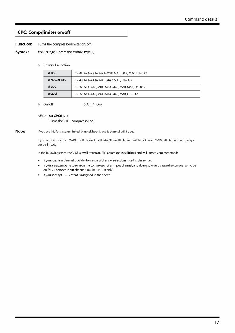
Function: Turns the compressor/limiter on/off.
Syntax:
stxCPC
:a,b; (Command syntax: type 2)
a: Channel selection
b: On/off (0: Off, 1: On)
<Ex.>
stxCPC:I1,1;
Turns the CH 1 compressor on.
Note:
If you set this for a stereo-linked channel, both L and R channel will be set.
If you set this for either MAIN L or R channel, both MAIN L and R channel will be set, since MAIN L/R channels are always
stereo-linked.
In the following cases, the V-Mixer will return an ERR command (
stxERR:5;
) and will ignore your command:
•
If you specify a channel outside the range of channel selections listed in the syntax.
•
If you are attempting to turn on the compressor of an input channel, and doing so would cause the compressor to be
on for 25 or more input channels (M-400/M-380 only).
•
If you specify U1–U72 that is assigned to the above.
CPC: Comp/limiter on/off
M-480
I1–I48, AX1–AX16, MX1–MX8, MAL, MAR, MAC, U1–U72
M-400/M-380
I1–I48, AX1–AX16, MAL, MAR, MAC, U1–U72
M-300
I1–I32, AX1–AX8, MX1–MX4, MAL, MAR, MAC, U1–U32
M-200i
I1–I32, AX1–AX8, MX1–MX4, MAL, MAR, U1–U32
17
Page 18
Command details
Function: Sets the AUX send level and AUX pan for input channel or MAIN.
Syntax:
stxAXC
:a,b,c,d; (Command syntax: type 2)
a: Channel selection
b: AUX channel selection
c: AUX send level (INF, -80.0–10.0) *0.1 dB steps
d: AUX pan (L63–C–R63) *Steps of 1
<Ex.>
stxAXC:I1,AX1,4.0,R30;
Sets the AUX 1 send level to +4.0 dB, and the AUX pan to R30 for CH1.
Note:
If you set the AUX send level for a stereo-linked channel, both L and R channel will be set. However, the AUX pan can be set
individually for L and R.
If you set the AUX send level for either MAIN L or R channel, both MAIN L and R channel will be set. However, the AUX pan
can be set individually for MAIN L and R.
If you specify an AUX channel that is not stereo-linked, the V-Mixer will ignore the AUX pan parameter.
In the following cases, the V-Mixer will return an ERR command (
stxERR:5;
) and will ignore your command:
•
If you specify a channel outside the range of channel selections listed in the syntax.
•
If you specify U1–U72 that is assigned to the above.
If you specify R1–R6, left side of the channel (RTN 1L, RTN 2L, ... or RTN 6L) will be selected for the AUX pan (M-480).
AXC: AUX send setting
M-480
I1–I48, R1–R6, R1L–R6R, U1–U72
M-400/M-380
I1–I48, MAL, MAR, MAC, U1–U72
M-300
I1–I32, U1–U32
M-200i
I1–I32, U1–U32
M-480
AX1–AX16
M-400/M-380
AX1–AX16
M-300
AX1–AX8
M-200i
AX1–AX8
18
Page 19
Command details
Function: Sets the MATRIX send level and MATRIX pan for input channel, AUX, or MAIN.
Syntax: stxMXC:a,b,c,d; (Command syntax: type 2)
a: Channel selection
b: MATRIX channel selection
c: MATRIX send level (INF, -80.0–10.0) *0.1 dB steps
d: MATRIX pan (L63–C–R63) *Steps of 1
<Ex.> stxMXC: AX1,MX1,4.0,R30;
Sets the MATRIX 1 send level to +4.0 dB, and the MATRIX pan to R30 for AUX 1.
Note: If you set the MATRIX send level for a stereo-linked channel, both L and R channel will be set. However, the MATRIX pan can
be set individually for L and R.
If you set the MATRIX send level for either MAIN L or R channel, both MAIN L and R channel will be set. However, the MATRIX
pan can be set individually for MAIN L and R.
If you specify a MATRIX channel that is not stereo-linked, the V-Mixer will ignore the MATRIX pan parameter.
In the following cases, the V-Mixer will return an ERR command (stxERR:5;) and will ignore your command:
• If you specify a channel outside the range of channel selections listed in the syntax.
• If you specify U1–U72 that is assigned to the above.
If you specify R1–R6, left side of the channel (RTN 1L, RTN 2L, ... or RTN 6L) will be selected for the MATRIX pan (M-480).
MXC: MATRIX send setting
M-480 I1–I48, R1–R6, R1L–R6R, AX1–AX16, MX1–MX8, MAL, MAR, MAC, U1–U72
M-400/M-380 AX1–AX16, MAL, MAR, MAC, U1–U72
M-300 I1–I32, AX1–AX8, MAL, MAR, MAC, U1–U32
M-200i I1–I32, AX1–AX8, MAL, MAR, U1–U32
M-480 MX1–MX8
M-400/M-380 MX1–MX8
M-300 MX1–MX4
M-200i MX1–MX4
19
Page 20
Command details
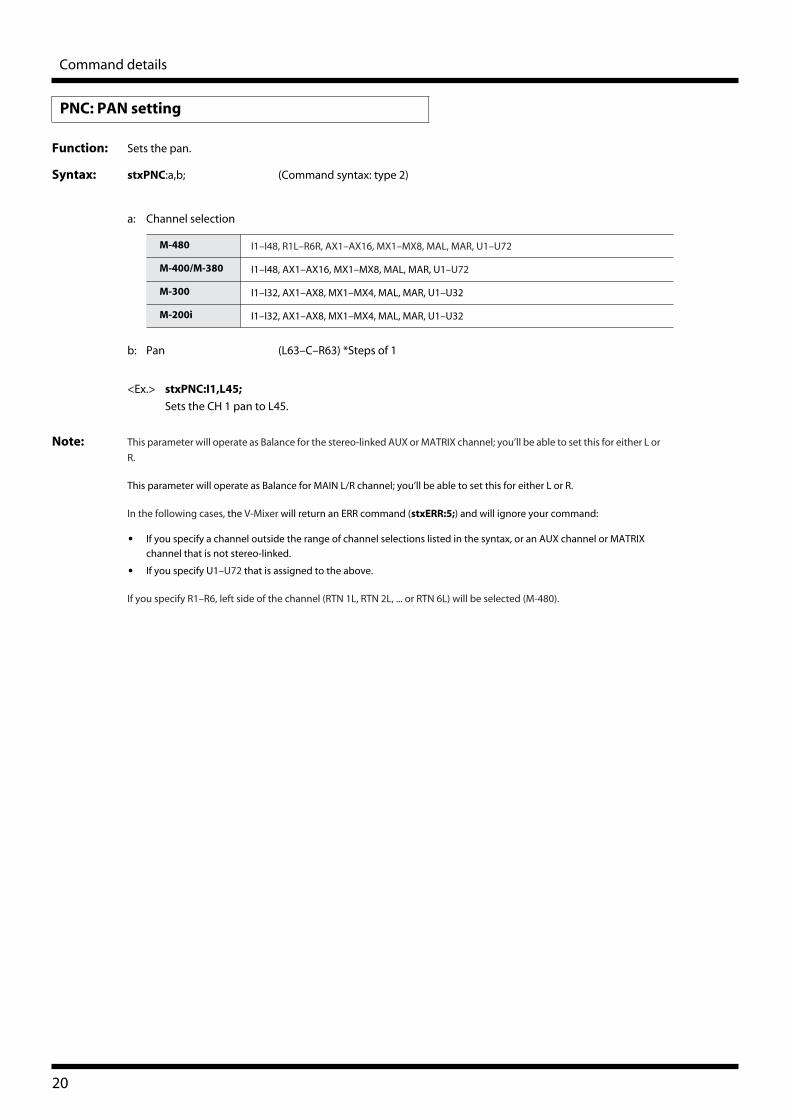
Function: Sets the pan.
Syntax: stxPNC:a,b; (Command syntax: type 2)
a: Channel selection
b: Pan (L63–C–R63) *Steps of 1
<Ex.> stxPNC:I1,L45;
Sets the CH 1 pan to L45.
Note: This parameter will operate as Balance for the stereo-linked AUX or MATRIX channel; you’ll be able to set this for either L or
R.
This parameter will operate as Balance for MAIN L/R channel; you’ll be able to set this for either L or R.
In the following cases, the V-Mixer will return an ERR command (stxERR:5;) and will ignore your command:
• If you specify a channel outside the range of channel selections listed in the syntax, or an AUX channel or MATRIX
channel that is not stereo-linked.
• If you specify U1–U72 that is assigned to the above.
If you specify R1–R6, left side of the channel (RTN 1L, RTN 2L, ... or RTN 6L) will be selected (M-480).
PNC: PAN setting
M-480 I1–I48, R1L–R6R, AX1–AX16, MX1–MX8, MAL, MAR, U1–U72
M-400/M-380 I1–I48, AX1–AX16, MX1–MX8, MAL, MAR, U1–U72
M-300 I1–I32, AX1–AX8, MX1–MX4, MAL, MAR, U1–U32
M-200i I1–I32, AX1–AX8, MX1–MX4, MAL, MAR, U1–U32
20
Page 21
Command details
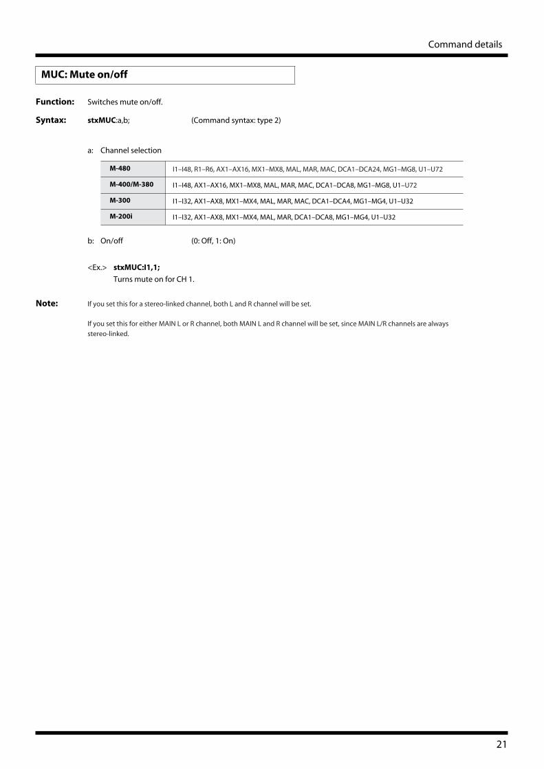
Function: Switches mute on/off.
Syntax: stxMUC:a,b; (Command syntax: type 2)
a: Channel selection
b: On/off (0: Off, 1: On)
<Ex.> stxMUC:I1,1;
Turns mute on for CH 1.
Note: If you set this for a stereo-linked channel, both L and R channel will be set.
If you set this for either MAIN L or R channel, both MAIN L and R channel will be set, since MAIN L/R channels are always
stereo-linked.
MUC: Mute on/off
M-480 I1–I48, R1–R6, AX1–AX16, MX1–MX8, MAL, MAR, MAC, DCA1–DCA24, MG1–MG8, U1–U72
M-400/M-380 I1–I48, AX1–AX16, MX1–MX8, MAL, MAR, MAC, DCA1–DCA8, MG1–MG8, U1–U72
M-300 I1–I32, AX1–AX8, MX1–MX4, MAL, MAR, MAC, DCA1–DCA4, MG1–MG4, U1–U32
M-200i I1–I32, AX1–AX8, MX1–MX4, MAL, MAR, DCA1–DCA8, MG1–MG4, U1–U32
21
Page 22
Command details
Function: Sets the fader level.
Syntax: stxFDC:a,b; (Command syntax: type 2)
a: Channel selection
b: Fader level (INF, -80.0–10.0) *0.1 dB steps
<Ex.> stxFDC:I1,INF;
Sets the CH 1 fader to -Inf.
Note: If you set this for a stereo-linked channel, both L and R channel will be set.
If you set this for either MAIN L or R channel, both MAIN L and R channel will be set, since MAIN L/R channels are always
stereo-linked.
If you specify MG1–MG8 as the channel selection, the V-Mixer will return an ERR command (stxERR:5;), and will ignore the
command.
FDC: Fader level
M-480 I1–I48, R1–R6, AX1–AX16, MX1–MX8, MAL, MAR, MAC, DCA1–DCA24, U1–U72
M-400/M-380 I1–I48, AX1–AX16, MX1–MX8, MAL, MAR, MAC, DCA1–DCA8, U1–U72
M-300 I1–I32, AX1–AX8, MX1–MX4, MAL, MAR, MAC, DCA1–DCA4, U1–U32
M-200i I1–I32, AX1–AX8, MX1–MX4, MAL, MAR, DCA1–DCA8, U1–U32
22
Page 23
Command details
Function: Sets the fader level as a relative value.
Syntax: stxRFC:a,b; (Command syntax: type 2)
a: Channel selection
b: Relative fader level (-99.9–99.9) *0.1 dB steps
<Ex.> stxRFC: I1,-1.0;
Sets the CH 1 fader to -1.0 dB.
Note: If you set this for a stereo-linked channel, both L and R channel will be set.
If you set this for either MAIN L or R channel, both MAIN L and R channel will be set, since MAIN L/R channels are always
stereo-linked.
In the following cases, the V-Mixer will return an ERR command (stxERR:5;) and will ignore your command:
• If you specify 0.0 as the relative fader level.
• If you specify a positive value for the relative fader level for a channel with a fader level of 10.0 dB.
• If you specify a negative value for the relative fader level for a channel with a fader level of -Inf dB.
• If you specify MG1–MG8 as the channel selection.
RFC: Relative fader level
M-480 I1–I48, R1–R6, AX1–AX16, MX1–MX8, MAL, MAR, MAC, DCA1–DCA24, U1–U72
M-400/M-380 I1–I48, AX1–AX16, MX1–MX8, MAL, MAR, MAC, DCA1–DCA8, U1–U72
M-300 I1–I32, AX1–AX8, MX1–MX4, MAL, MAR, MAC, DCA1–DCA4, U1–U32
M-200i I1–I32, AX1–AX8, MX1–MX4, MAL, MAR, DCA1–DCA8, U1–U32
23
Page 24
Command details
Function: Recalls a scene memory.
Syntax: stxSCC:a; (Command syntax: type 2)
a: Scene number (000–299)
<Ex.> stxSCC:010;
Recalls scene number 010.
Note: If you specify a blank scene, the V-Mixer will return an ERR command (stxERR:5;) and ignore your command.
Function: Recalls a scene memory relatively; e.g., “the previous memory” or “two scenes ahead.”
Note: stxRSC:a; (Command syntax: type 2)
a: Relative scene number (-299–299)
<Ex.> stxRSC: -3;
Recalls the scene memory three memories earlier than the current scene number.
Note: If the scene memory number specified by relative scene is one of the following scenes, the V-Mixer will return an ERR
command (stxERR:5;) and ignore your command:
• A blank scene.
• A scene number outside the range of 0–299.
SCC: Scene recall
RSC: Relative scene recall
24
Page 25
Command details
Function: Stores a scene memory.
Syntax: stxSSC: a; (Command syntax: type 2)
stxSSC: a,b; (Command syntax: type 2)
stxSSC: a,b,c; (Command syntax: type 2)
a: Scene number (000–299)
b: Scene name (maximum 16 characters, variable length)
c: M-48 memory number (0: Off, 01–16: Memory 1–16)
<Ex.> stxSSC: 010, Scene 10, 05;
Stores current mixing parameters to scene number 010 with scene name “Scene 10”.
Also stores connected M-48’s current memory to memory number 5.
Note: If the scene number you specify is locked, the V-Mixer will return an ERR command (stxERR: 6;) and will ignore your
command.
If you don’t specify a Scene name, the current scene name will be used.
If you don’t specify an M-48 memory number, “M-48 MEMORY” settings of the current scene will be used. You can see the
“M-48 MEMORY” settings in the SCENE STORE popup on the V-Mixer.
SSC: Scene store
25
Page 26
Command details
Function: Sets the input patchbay.
Syntax: stxPIC: a,b; (Command syntax type 2)
a: Channel selection
On M-480, the cascade inputs can be specified as the channel selection parameter:
b: Input port selection
PIC: Input patchbay setting
M-480 I1–I48, R1L–R6R
M-400/M-380 I1–I48
M-300 I1–I32
M-200i I1–I32
Cascade inputs Selection parameters
CAS IN MAIN L, CAS IN MAIN R, CAS IN MAIN C CSMAL, CSMAR, CSMAC
CAS IN AUX 1, CAS IN AUX 2, ... CAS IN AUX 16 CSAX1, CSAX2, ... CSAX16
CAS IN MTX 1, CAS IN MTX 2, ... CAS IN MTX 8 CSMX1, CSMX2, ... CSMX8
CAS IN SOLO L, CAS IN SOLO R CSSOL, CSSOR
Input ports Selection parameters
M-480 REAC A IN 1, REAC A IN 2, ... REAC A IN 40 RAI1, RAI2, ... RAI40
REAC B IN 1, REAC B IN 2, ... REAC B IN 40 RBI1, RBI2, ... RBI40
CONSOLE IN 1, CONOSOLE IN 2, ... CONSOLE IN 8 CI1, CI2, ... CI8
STEREO IN L, STEREO IN R STIL, STIR
FX1 OUT L, FX1 OUT R, ... FX6 OUT R FX1L, FX1R, ... FX6R
PLAY L, PLAY R PLAYL, PLAYR
NONE OFF
M-400/M-380 REAC A IN 1, REAC A IN 2, ... REAC A IN 40 RAI1, RAI2, ... RAI40
REAC B IN 1, REAC B IN 2, ... REAC B IN 40 RBI1, RBI2, ... RBI40
CONSOLE IN 1, CONOSOLE IN 2, ... CONSOLE IN 8 CI1, CI2, ... CI8
STEREO IN L, STEREO IN R STIL, STIR
FX1 OUT L, FX1 OUT R, ... FX4 OUT R FX1L, FX1R, ... FX4R
PLAY L, PLAY R PLAYL, PLAYR
NONE OFF
M-300 REAC A IN 1, REAC A IN 2, ... REAC A IN 40 RAI1, RAI2, ... RAI40
REAC B IN 1, REAC B IN 2, ... REAC B IN 40 RBI1, RBI2, ... RBI40
CONSOLE IN 1, CONOSOLE IN 2, ... CONSOLE IN 12 CI1, CI2, ... CI12
FX1 OUT L, FX1 OUT R, ... FX4 OUT R FX1L, FX1R, ... FX4R
PLAY L, PLAY R PLAYL, PLAYR
NONE OFF
26
Page 27
Command details
<Ex.> stxPIC:I1,RAI21;
Sets the CH1 input source to the REAC A IN 21.
Note: In the following cases, the V-Mixer will return an ERR command (stxERR:5;) and will ignore your command:
• If you specify a channel outside the range of channel selections listed in the syntax.
M-200i REAC IN 1, REAC IN 2, ... REAC IN 40 RAI1, RAI2, ... RAI40
INPUT 1, INPUT 2, ... INPUT 24 CI1, CI2, ... CI24
FX1 OUT L, FX1 OUT R, ... FX4 OUT R FX1L, FX1R, ... FX4R
PLAY L, PLAY R PLAYL, PLAYR
NONE OFF
Input ports Selection parameters
27
Page 28
Command details
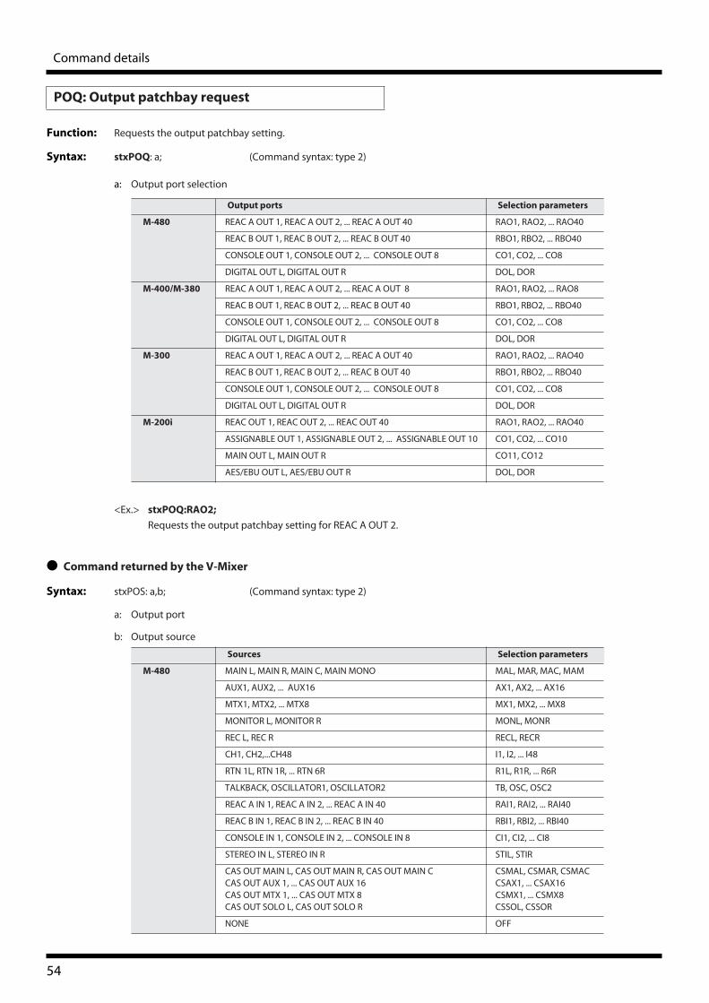
Function: Sets the output patchbay.
Syntax: stxPOC: a,b; (Command syntax type 2)
a: Output port selection
b: Output source selection
POC: Output patchbay setting
Output ports Selection parameters
M-480 REAC A OUT 1, REAC A OUT 2, ... REAC A OUT 40 RAO1, RAO2, ... RAO40
REAC B OUT 1, REAC B OUT 2, ... REAC B OUT 40 RBO1, RBO2, ... RBO40
CONOLE OUT 1, CONSOLE OUT 2, ... CONSOLE OUT 8 CO1, CO2, ... CO8
DIGITAL OUT L, DIGITAL OUT R DOL, DOR
M-400/M-380 REAC A OUT 1, REAC A OUT 2, ... REAC A OUT 8 RAO1, RAO2, ... RAO8
REAC B OUT 1, REAC B OUT 2, ... REAC B OUT 40 RBO1, RBO2, ... RBO40
CONOLE OUT 1, CONSOLE OUT 2, ... CONSOLE OUT 8 CO1, CO2, ... CO8
DIGITAL OUT L, DIGITAL OUT R DOL, DOR
M-300 REAC A OUT 1, REAC A OUT 2, ... REAC A OUT 40 RAO1, RAO2, ... RAO40
REAC B OUT 1, REAC B OUT 2, ... REAC B OUT 40 RBO1, RBO2, ... RBO40
CONOLE OUT 1, CONSOLE OUT 2, ... CONSOLE OUT 8 CO1, CO2, ... CO8
DIGITAL OUT L, DIGITAL OUT R DOL, DOR
M-200i REAC A OUT 1, REAC A OUT 2, ... REAC A OUT 40 RAO1, RAO2, ... RAO40
REAC B OUT 1, REAC B OUT 2, ... REAC B OUT 40 RBO1, RBO2, ... RBO40
ASSIGNABLE OUT 1, ASSIGNABLE OUT 2, ... ASSIGNABLE OUT 10 CO1, CO2, ... CO10
MAIN OUT L, MAIN OUT R CO11, CO12
AES/EBU OUT L, AES/EBU OUT R DOL, DOR
Sources Selection parameters
M-480 MAIN L, MAIN R, MAIN C, MAIN MONO MAL, MAR, MAC, MAM
AUX1, AUX2, ... AUX16 AX1, AX2, ... AX16
MTX1, MTX2, ... MTX8 MX1, MX2, ... MX8
MONITOR L, MONITOR R MONL, MONR
REC L, REC R RECL, RECR
CH1, CH2, ...CH48 I1, I2, ... I48
RTN 1L, RTN 1R, ... RTN 6R R1L, R1R, ... R6R
TALKBACK, OSCILLATOR1, OSCILLATOR2 TB, OSC, OSC2
REAC A IN 1, REAC A IN 2, ... REAC A IN 40 RAI1, RAI2, ... RAI40
REAC B IN 1, REAC B IN 2, ... REAC B IN 40 RBI1, RBI2, ... RBI40
CONSOLE IN 1, CONSOLE IN 2, ... CONSOLE IN 8 CI1, CI2, ... CI8
STEREO IN L, STEREO IN R STIL, STIR
CAS OUT MAIN L, CAS OUT MAIN L, CAS OUT MAIN CCAS OUT AUX 1, ... CAS OUT AUX 16CAS OUT MTX 1, ... CAS OUT MTX 8CAS OUT SOLO L, CAS OUT SOLO R
CSMAL, CSMAR, CSMACCSAX1, ... CSAX16CSMX1, ... CSMX8CSSOL, CSSOR
NONE OFF
28
Page 29
Command details
<Ex.> stxPOC:RAO1,MAL;
Sets the REAC A OUT 1 output source to the MAIN L.
Note: In the following cases, the V-Mixer will return an ERR command (stxERR:5;) and will ignore your command:
• If you specify a channel outside the range of channel selections listed in the syntax.
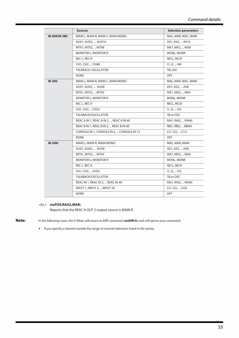
M-400/M-380 MAIN L, MAIN R, MAIN C, MAIN MONO MAL, MAR, MAC, MAM
AUX1, AUX2, ... AUX16 AX1, AX2, ... AX16
MTX1, MTX2, ... MTX8 MX1, MX2, ... MX8
MONITOR L, MONITOR R MONL, MONR
REC L, REC R RECL, RECR
CH1, CH2, ... CH48 I1, I2, ... I48
TALKBACK, OSCILLATOR TB, OSC
NONE OFF
M-300 MAIN L, MAIN R, MAIN C, MAIN MONO MAL, MAR, MAC, MAM
AUX1, AUX2, ... AUX8 AX1, AX2, ... AX8
MTX1, MTX2, ... MTX4 MX1, MX2, ... MX4
MONITOR L, MONITOR R MONL, MONR
REC L, REC R RECL, RECR
CH1, CH2, ... CH32 I1, I2, ... I32
TALKBACK/OSCILLATOR TB or OSC
REAC A IN 1, REAC A IN 2, ... REAC A IN 40 RAI1, RAI2, ... RAI40
REAC B IN 1, REAC B IN 2, ... REAC B IN 40 RBI1, RBI2, ... RBI40
CONSOLE IN 1, CONSOLE IN 2, ... CONSOLE IN 12 CI1, CI2, ... CI12
NONE OFF
M-200i MAIN L, MAIN R, MAIN MONO MAL, MAR, MAM
AUX1, AUX2, ... AUX8 AX1, AX2, ... AX8
MTX1, MTX2, ... MTX4 MX1, MX2, ... MX4
MONITOR L, MONITOR R MONL, MONR
REC L, REC R RECL, RECR
CH1, CH2, ... CH32 I1, I2, ... I32
TALKBACK/OSCILLATOR TB or OSC
REAC IN 1, REAC IN 2, ... REAC IN 40 RAI1, RAI2, ... RAI40
INPUT 1, INPUT 2, ... INPUT 24 CI1, CI2, ... CI24
NONE OFF
Sources Selection parameters
29
Page 30
Command details
Function: Lock or Unlock the console operation
Syntax: stxLCC:a; (Command syntax: type 2)
a: Lock/Unlock (0: Unlock, 1: Lock)
<Ex.> stxLCC:1;
Lock the console operation.
Note: This command enforces to lock or unlock the console operation even in case user password is set.
In the following cases, the V-Mixer will return ERR command (stxERR:5;) and will ignore your command:
• If the console is in specified condition: stxERR:5;
• If operation cannot be locked because some operation on console is currently performed etc.: stxERR:2;
LCC: LOCK/UNLOCK the console operation
30
Page 31
Command details
Function: Sets the display blackout or cancel blackout.
Syntax: stxBLC:a; (Command syntax: type 2)
a: Blackout/cancel blackout (0: Cancel blackout, 1: Blackout)
<Ex.> stxBLC:1;
Sets the display blackout.
Note: In the following cases, the V-Mixer will return ERR command(stxERR:5;)and will ignore your command:
• If the console is in the status you have specified.
Function: Sets the display brightness.
Syntax: stxDBC:a; (Command syntax: type 2)
a: Brightness(%) (0 to100)
<Ex.> stxDBC:50;
Sets the display brightness to 50%.
Note: The steps of display brightness adjustment differ depending on the model.
Changes of brightness may not be seen with specific values.
BLC: Display blackout/cancel blackout
DBC: Display brightness setting
M-480 8 steps
M-400/M-380 11 steps
M-300 11 steps
M-200i 2 steps
31
Page 32
Command details
Function: Sets the panel brightness.
Syntax: stxPBC:a; (Command syntax: type 2)
a: Brightness(%) (0 to100)
<Ex.> stxPBC:50;
Sets the panel brightness to 50%.
Note: The panel brightness adjustment can be executed with 11 steps.
Changes of brightness may not be seen with specific values.
Function: Sets brightness of the lamp connected to the LAMP jack.
Syntax: stxLBC:a; (Command syntax: type 2)
a: Brightness(%) (0 to100)
<Ex.> stxLBC:50;
Sets the lamp brightness to 50%.
Note: Since the M-300 and the M-200i are not equipped with the LAMP jack, this is invalid.
The lamp brightness adjustment can be executed with 11 steps.
Changes of brightness may not be seen with specific values.
PBC: Panel brightness setting
LBC: Lamp brightness setting
32
Page 33
Command details
Function: Switches monitor dimmer on/off.
Syntax: stxDMC:a; (Command syntax: type 2)
a: On/off (0: Off, 1: On)
<Ex.> stxDMC:1;
Turns monitor dimmer.
Note: In the following cases, the V-Mixer will return ERR command(stxERR:5;)and will ignore your command:.
• If the console is in the status you have specified.
DMC: Monitor dimmer on/off
33
Page 34
Command details
Function: Controls the transport of USB memory recorder.
Syntax: stxRTC:a; (Command syntax: type 2)
a: Transport
0 or S Stop playback/recording.
1 or P Starts playback. Starts recording when recording is paused.
2 or R Make the unit to REC pause status.
<Ex.> stxRTC:1;
Starts playback the song. Starts recording the song when recording is paused.
Function: Jumps to specified location of USB memory recorder.
Syntax: stxRLC:HHhMMmSSs; (Command syntax: type 2)
HH Hour
MM Minute
SS Second
<Ex.> stxRLC:02m34s;
Jumps to 02:34.
Note:
• This command is valid only during playback
• The value of h/m/s not specificated in the syntax will be 00.
• Th h/m/s can be capital or small.
RTC: USB memory recorder transport
RLC: USB memory recorder locate
34
Page 35
Command details
Function: Select the current song of USB memory recorder.
Syntax: stxRIC:a; (Command syntax: type 2)
a: Song number
0 to 999 Song number
+1 to +999 Relative song number
-999 to -1 Relative song number
N Next song
P Previous song
<Ex.> stxRIC:1;
Select song 1.
<Ex.> stxRIC:-1;
Select the previous song.
RIC: Song select
35
Page 36
Command details
Function: Requests the channel/group name.
Syntax: stxCNQ:a; (Command syntax: type 2)
a: Channel selection
<Ex.> stxCNQ:I1;
Requests the channel name of CH 1.
● Command returned by the V-Mixer
Syntax: stxCNS:a,b; (Command syntax: type 2)
a: Channel number
b: Channel name (fixed at six characters)
<Ex.> stxCNS:I1,”A.BASS”;
Output the channel name A.BASS for CH 1.
Note: If the channel name is blank, the output will be six spaces.
Request commands
CNQ: Channel name request
M-480 I1–I48, R1–R6, AX1–AX16, MX1–MX8, MAL, MAR, MAC, DCA1–DCA24, MG1–MG8, U1–U72
M-400/M-380 I1–I48, AX1–AX16, MX1–MX8, MAL, MAR, MAC, DCA1–DCA8, MG1–MG8, U1–U72
M-300 I1–I32, AX1–AX8, MX1–MX4, MAL, MAR, MAC, DCA1–DCA4, MG1–MG4, U1–U32
M-200i I1–I32, AX1–AX8, MX1–MX4, MAL, MAR, DCA1–DCA8, MG1–MG4, U1–U32
M-480 I1–I48, R1–R6, AX1–AX16, MX1–MX8, MAL, MAR, MAC, DCA1–DCA24, MG1–MG8, U1–U72
M-400/M-380 I1–I48, AX1–AX16, MX1–MX8, MAL, MAR, MAC, DCA1–DCA8, MG1–MG8, U1–U72
M-300 I1–I32, AX1–AX8, MX1–MX4, MAL, MAR, MAC, DCA1–DCA4, MG1–MG4, U1–U32
M-200i I1–I32, AX1–AX8, MX1–MX4, MAL, MAR,, DCA1–DCA8, MG1–MG4, U1–U32
36
Page 37
Command details
Function: Requests the on/off status of the +48V phantom power supply.
Syntax: stxPTQ:a; (Command syntax: type 2)
a: Channel selection
<Ex.> stxPTQ:I1;
Requests the on/off status of the +48 V phantom power supply for CH 1.
● Command returned by the V-Mixer
Syntax: stxPTS:a,b; (Command syntax: type 2)
a: Channel number
b: On/off (0: Off, 1: On)
<Ex.> stxPTS:I1,0;
Reports that the CH1 phantom power is off.
Note: In the following cases, the V-Mixer will return an ERR command (stxERR:5;) and will ignore your command:
• If you specify a channel that does not have phantom power.
• If you specify U1–U72 that is assigned to the above.
PTQ: Phantom power supply request
M-480 I1–I48, R1L–R6R, U1–U72
M-400/M-380 I1–I48, U1–U72
M-300 I1–I32, U1–U32
M-200i I1–I32, U1–U32
M-480 I1–I48, R1L–R6R, U1–U72
M-400/M-380 I1–I48, U1–U72
M-300 I1–I32, U1–U32
M-200i I1–I32, U1–U32
37
Page 38
Command details
Function: Requests the on/off status of ϕ (phase/polarity).
Syntax: stxPSQ:a; (Command syntax: type 2)
a: Channel selection
<Ex.> stxPSQ:I1;
Requests the on/off status of ϕ (phase/polarity) for CH 1.
● Command returned by the V-Mixer
Syntax: stxPSS:a,b; (Command syntax: type 2)
a: Channel number
b: On/off (0: Off, 1: On)
<Ex.> stxPSS:I1,0;
Reports that the CH 1 ϕ (phase/polarity) is off.
Note: In the following cases, the V-Mixer will return an ERR command (stxERR:5;) and will ignore your command:
• If you specify a channel outside the range of channel selections listed in the syntax.
• If you specify U1–U72 that is assigned to the above.
PSQ: ϕ (phase/polarity) request
M-480 I1–I48, R1L–R6R, U1–U72
M-400/M-380 I1–I48, U1–U72
M-300 I1–I32, U1–U32
M-200i I1–I32, U1–U32
M-480 I1–I48, R1L–R6R, U1–U72
M-400/M-380 I1–I48, U1–U72
M-300 I1–I32, U1–U32
M-200i I1–I32, U1–U32
38
Page 39
Command details
Function: Requests the pad and preamp gain settings of a channel.
Syntax: stxPGQ:a; (Command syntax: type 2)
a: Channel selection
<Ex.> stxPGQ:I1;
Requests the pad and preamp gain settings for CH 1.
● Command returned by the V-Mixer
Syntax: stxPGS:a,b,c; (Command syntax: type 2)
a: Channel number
b: Pad on/off (0: Off, 1: On)
c: Gain (10 to -65) *1 dB steps
<Ex.> stxPGS:I1,0,-55;
Reports that the CH 1 pad is off and the gain setting is -55 dBu.
Note: If you specify a channel that has no pad, the V-Mixer will return “0” as the value of the Pad.
In the following cases, the V-Mixer will return an ERR command (stxERR:5;) and will ignore your command:
• If you specify a channel that has no gain adjustment.
• If you specify U1–U72 that is assigned to the above.
PGQ: Preamp gain request
M-480 I1–I48, R1L–R6R, U1–U72
M-400/M-380 I1–I48, U1–U72
M-300 I1–I32, U1–U32
M-200i I1–I32, U1–U32
M-480 I1–I48, R1L–R6R, U1–U72
M-400/M-380 I1–I48, U1–U72
M-300 I1–I32, U1–U32
M-200i I1–I32, U1–U32
39
Page 40
Command details
Function: Requests the filter on/off setting.
Syntax: stxFLQ:a; (Command syntax: type 2)
a: Channel selection
<Ex.> stxFLQ:I1;
Requests the CH 1 filter on/off setting.
● Command returned by the V-Mixer
Syntax: stxFLS:a,b; (Command syntax: type 2)
a: Channel number
b: On/off (0: Off, 1: On)
<Ex.> stxFLS:I1,0;
Reports that the CH 1 filter is off.
Note: If you select a stereo-linked input channel, the same value will be returned for L or R.
In the following cases, the V-Mixer will return an ERR command (stxERR:5;) and will ignore your command:
• If you specify a channel outside the range of channel selections listed in the syntax.
• If you specify U1–U72 that is assigned to the above.
FLQ: Filter request
M-480 I1–I48, U1–U72
M-400/M-380 I1–I48, U1–U72
M-300 I1–I32, U1–U32
M-200i I1–I32, U1–U32
M-480 I1–I48, U1–U72
M-400/M-380 I1–I48, U1–U72
M-300 I1–I32, U1–U32
M-200i I1–I32, U1–U32
40
Page 41
Command details
Function: Requests the on/off setting of the EQ.
Syntax: stxEQQ:a; (Command syntax: type 2)
a: Channel selection
<Ex.> stxEQQ:I1;
Requests the on/off setting of the CH 1 EQ.
● Command returned by the V-Mixer
Syntax: stxEQS:a,b; (Command syntax: type 2)
a: Channel number
b: On/off (0: Off, 1: On)
<Ex.> stxEQS:I1,0;
Reports that the CH 1 EQ is off.
Note: If you specify a stereo-linked channel, the same value will be returned for L or R.
If you specify MAIN L/R channel, the same value will be returned for L or R.
In the following cases, the V-Mixer will return an ERR command (stxERR:5;) and will ignore your command:
• If you specify a channel outside the range of channel selections listed in the syntax.
• If you specify U1–U72 that is assigned to the above.
EQQ: EQ request
M-480 I1–I48, AX1–AX16, MX1–MX8, MAL, MAR, MAC, U1–U72
M-400/M-380 I1–I48, AX1–AX16, MAL, MAR, MAC, U1–U72
M-300 I1–I32, AX1–AX8, MX1–MX4, MAL, MAR, MAC, U1–U32
M-200i I1–I32, AX1–AX8, MX1–MX4, MAL, MAR, U1–U32
M-480 I1–I48, AX1–AX16, MX1–MX8, MAL, MAR, MAC, U1–U72
M-400/M-380 I1–I48, AX1–AX16, MAL, MAR, MAC, U1–U72
M-300 I1–I32, AX1–AX8, MX1–MX4, MAL, MAR, MAC, U1–U32
M-200i I1–I32, AX1–AX8, MX1–MX4, MAL, MAR, U1–U32
41
Page 42
Command details
Function: Requests the gate on/off setting.
Syntax: stxGTQ:a; (Command syntax: type 2)
a: Channel selection
<Ex.> stxGTQ:I1;
Requests the gate on/off setting of CH 1.
● Command returned by the V-Mixer
Syntax: stxGTS:a,b; (Command syntax: type 2)
a: Channel number
b: On/off (0: Off, 1: On)
<Ex.> stxGTS:I1,0;
Reports that the CH 1 gate is off.
Note: If you specify a stereo-linked input channel, the same value will be returned for L or R.
In the following cases, the V-Mixer will return an ERR command (stxERR:5;) and will ignore your command:
• If you specify a channel outside the range of channel selections listed in the syntax.
• If you specify U1–U72 that is assigned to the above.
GTQ: Gate request
M-480 I1–I48, U1–U72
M-400/M-380 I1–I48, U1–U72
M-300 I1–I32, U1–U32
M-200i I1–I32, U1–U32
M-480 I1–I48, U1–U72
M-400/M-380 I1–I48, U1–U72
M-300 I1–I32, U1–U32
M-200i I1–I32, U1–U32
42
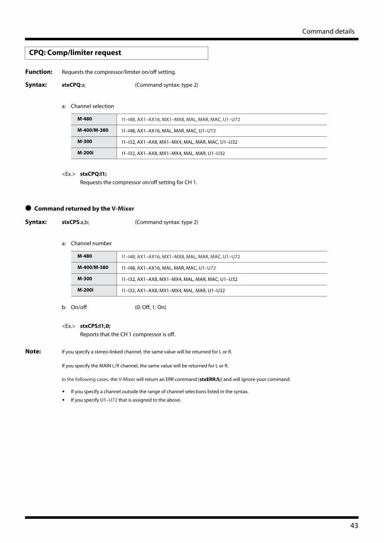
Page 43
Command details
Function: Requests the compressor/limiter on/off setting.
Syntax: stxCPQ:a; (Command syntax: type 2)
a: Channel selection
<Ex.> stxCPQ:I1;
Requests the compressor on/off setting for CH 1.
● Command returned by the V-Mixer
Syntax: stxCPS:a,b; (Command syntax: type 2)
a: Channel number
b: On/off (0: Off, 1: On)
<Ex.> stxCPS:I1,0;
Reports that the CH 1 compressor is off.
Note: If you specify a stereo-linked channel, the same value will be returned for L or R.
If you specify the MAIN L/R channel, the same value will be returned for L or R.
In the following cases, the V-Mixer will return an ERR command (stxERR:5;) and will ignore your command:
• If you specify a channel outside the range of channel selections listed in the syntax.
• If you specify U1–U72 that is assigned to the above.
CPQ: Comp/limiter request
M-480 I1–I48, AX1–AX16, MX1–MX8, MAL, MAR, MAC, U1–U72
M-400/M-380 I1–I48, AX1–AX16, MAL, MAR, MAC, U1–U72
M-300 I1–I32, AX1–AX8, MX1–MX4, MAL, MAR, MAC, U1–U32
M-200i I1–I32, AX1–AX8, MX1–MX4, MAL, MAR, U1–U32
M-480 I1–I48, AX1–AX16, MX1–MX8, MAL, MAR, MAC, U1–U72
M-400/M-380 I1–I48, AX1–AX16, MAL, MAR, MAC, U1–U72
M-300 I1–I32, AX1–AX8, MX1–MX4, MAL, MAR, MAC, U1–U32
M-200i I1–I32, AX1–AX8, MX1–MX4, MAL, MAR, U1–U32
43
Page 44
Command details
Function: Requests the AUX send level and AUX pan settings for input channel or MAIN.
Syntax: stxAXQ:a,b; (Command syntax: type 2)
a: Channel selection
b: AUX channel selection
<Ex.> stxAXQ:I1,AX3;
Requests the AUX 3 send level and AUX pan setting for CH1.
● Command returned by the V-Mixer
Syntax: stxAXS:a,b,c,d; (Command syntax: type 2)
a: Channel number
b: AUX channel number
c: AUX send level (INF, -80.0–10.0) *0.1 dB steps
d: AUX pan (L63–C–R63) *Steps of 1
<Ex.> stxAXS:I1,AX3,-6.5,C;
Reports that for CH 1, the AUX 3 send level is -6.5 dB and the AUX pan is at center.
AXQ: AUX send request
M-480 I1–I48, R1–R6, R1L–R6R, U1–U72
M-400/M-380 I1–I48, MAL, MAR, MAC, U1–U72
M-300 I1–I32, U1–U32
M-200i I1–I32, U1–U32
M-480 AX1–AX16
M-400/M-380 AX1–AX16
M-300 AX1–AX8
M-200i AX1–AX8
M-480 I1–I48, R1–R6, R1L–R6R, U1–U72
M-400/M-380 I1–I48, MAL, MAR, MAC, U1–U72
M-300 I1–I32, U1–U32
M-200i I1–I32, U1–U32
M-480 AX1–AX16
M-400/M-380 AX1–AX16
M-300 AX1–AX8
M-200i AX1–AX8
44
Page 45
Command details
Note: If you specify a stereo-linked channel, the same AUX send level value will be returned for both L and R. However, the AUX
pan can be requested individually for L and R.
If you specify the MAIN L/R channel, the same AUX send level value will be returned for L or R. However, the AUX pan can
be specified individually for L and R.
If you specify an AUX channel that is not stereo-linked, the V-Mixer will return “0” as the value of the AUX pan.
In the following cases, the V-Mixer will return an ERR command (stxERR:5;) and will ignore your command:
• If you specify a channel outside the range of channel selections listed in the syntax.
• If you specify U1–U72 that is assigned to the above.
45
Page 46
Command details
Function: Requests the MATRIX send level and MATRIX pan settings for input channel, AUX, or MAIN.
Syntax: stxMXQ:a,b; (Command syntax: type 2)
a: Channel selection
b: MATRIX channel selection
<Ex.> stxMXQ: AX1,MX3;
Requests the MATRIX 3 send level and MATRIX pan setting for AUX 1.
● Command returned by the V-Mixer
Syntax: stxMXS:a,b,c,d; (Command syntax: type 2)
a: Channel number
b: MATRIX channel number
c: MATRIX send level (INF, -80.0–10.0) *0.1 dB steps
d: MATRIX pan (L63–C–R63) *Steps of 1
<Ex.> stxMXS: AX1,MX3,-6.5,C;
Reports that for AUX 1, the MATRIX 3 send level is -6.5 dB and the MATRIX pan is at center.
MXQ: MATRIX send request
M-480 I1–I48, R1–R6, R1L–R6R, AX1–AX16, MAL, MAR, MAC, U1–U72
M-400/M-380 AX1–AX16, MAL, MAR, MAC, U1–U72
M-300 I1–I32, AX1–AX8, MAL, MAR, MAC, U1–U32
M-200i I1–I32, AX1–AX8, MAL, MAR, U1–U32
M-480 MX1–MX8
M-400/M-380 MX1–MX8
M-300 MX1–MX4
M-200i MX1–MX4
M-480 I1–I48, R1–R6, R1L–R6R, AX1–AX16, MAL, MAR, MAC, U1–U72
M-400/M-380 AX1–AX16, MAL, MAR, MAC, U1–U72
M-300 I1–I32, AX1–AX8, MAL, MAR, MAC, U1–U32
M-200i I1–I32, AX1–AX8, MAL, MAR, U1–U32
M-480 MX1–MX8
M-400/M-380 MX1–MX8
M-300 MX1–MX4
M-200i MX1–MX4
46
Page 47
Command details
Note: If you specify a stereo-linked channel, the same MATRIX send level value will be returned for both L and R. However, the
MATRIX pan can be requested individually for L and R.
If you specify the MAIN L/R channel, the same MATRIX send level value will be returned for L or R. However, the MATRIX
pan can be specified individually for L and R.
If you specify a MATRIX channel that is not stereo-linked, the V-Mixer will return “0” as the value of the MATRIX pan.
In the following cases, the V-Mixer will return an ERR command (stxERR:5;) and will ignore your command:
• If you specify a channel outside the range of channel selections listed in the syntax.
• If you specify U1–U72 that is assigned to the above.
47
Page 48
Command details
Function: Requests the pan setting.
Syntax: stxPNQ:a; (Command syntax: type 2)
a: Channel selection
<Ex.> stxPNQ:I1;
Requests the CH 1 setting.
● Command returned by the V-Mixer
Syntax: stxPNS:a,b; (Command syntax: type 2)
a: Channel number
b: Pan (L63–C–R63) *Steps of 1
<Ex.> stxPNS: I1,C;
Reports that the pan of CH 1 is set at the center.
Note: If you specify a stereo-linked AUX channel, the same value will be returned for L or R, since this parameter is operating as
Balance.
If you specify MAIN L/R channel, the same value will be returned for L or R, since this parameter is operating as Balance.
In the following cases, the V-Mixer will return an ERR command (stxERR:5;) and will ignore your command:
• If you specify a channel outside the range of channel selections listed in the syntax, or an AUX channel or MATRIX
channel that is not stereo-linked.
• If you specify U1–U72 that is assigned to the above.
PNQ: PAN request
M-480 I1–I48, R1L–R6R, AX1–AX16, MX1–MX8, MAL, MAR, U1–U72
M-400/M-380 I1–I48, AX1–AX16, MX1–MX8, MAL, MAR, U1–U72
M-300 I1–I32, AX1–AX8, MX1–MX4, MAL, MAR, U1–U32
M-200i I1–I32, AX1–AX8, MX1–MX4, MAL, MAR, U1–U32
M-480 I1–I48, R1L–R6R, AX1–AX16, MX1–MX8, MAL, MAR, U1–U72
M-400/M-380 I1–I48, AX1–AX16, MX1–MX8, MAL, MAR, U1–U72
M-300 I1–I32, AX1–AX8, MX1–MX4, MAL, MAR, U1–U32
M-200i I1–I32, AX1–AX8, MX1–MX4, MAL, MAR, U1–U32
48
Page 49
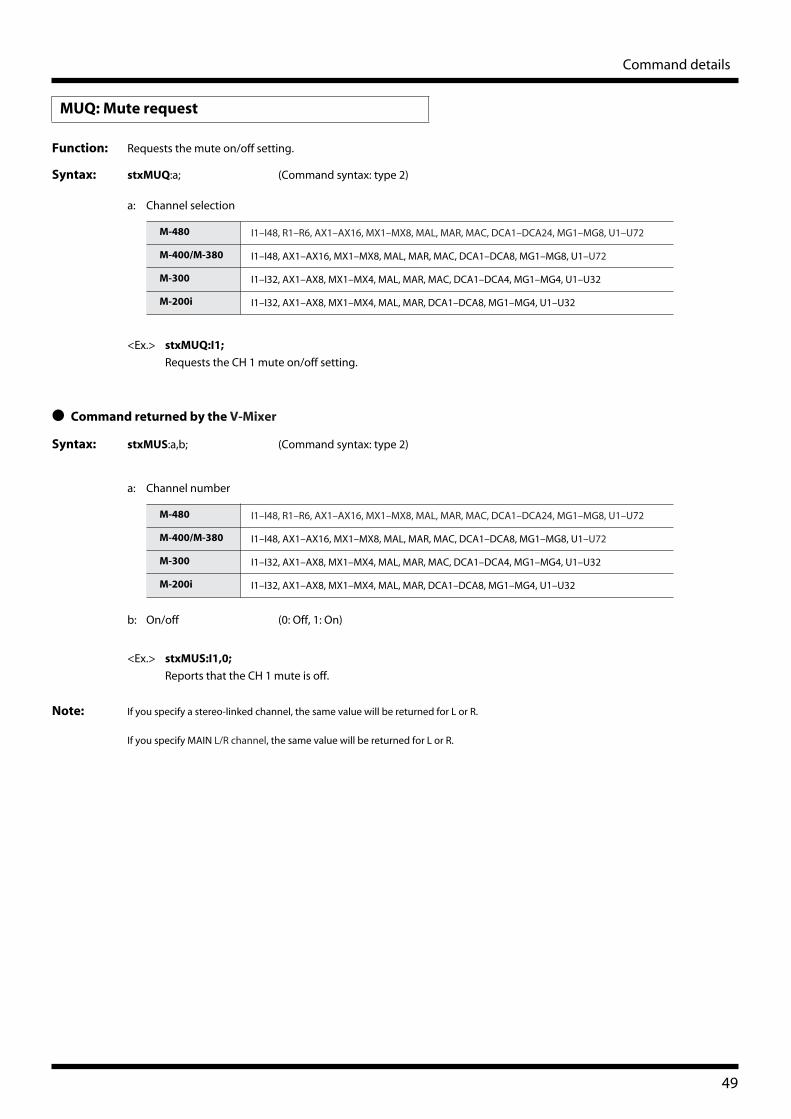
Command details
Function: Requests the mute on/off setting.
Syntax: stxMUQ:a; (Command syntax: type 2)
a: Channel selection
<Ex.> stxMUQ:I1;
Requests the CH 1 mute on/off setting.
● Command returned by the V-Mixer
Syntax: stxMUS:a,b; (Command syntax: type 2)
a: Channel number
b: On/off (0: Off, 1: On)
<Ex.> stxMUS:I1,0;
Reports that the CH 1 mute is off.
Note: If you specify a stereo-linked channel, the same value will be returned for L or R.
If you specify MAIN L/R channel, the same value will be returned for L or R.
MUQ: Mute request
M-480 I1–I48, R1–R6, AX1–AX16, MX1–MX8, MAL, MAR, MAC, DCA1–DCA24, MG1–MG8, U1–U72
M-400/M-380 I1–I48, AX1–AX16, MX1–MX8, MAL, MAR, MAC, DCA1–DCA8, MG1–MG8, U1–U72
M-300 I1–I32, AX1–AX8, MX1–MX4, MAL, MAR, MAC, DCA1–DCA4, MG1–MG4, U1–U32
M-200i I1–I32, AX1–AX8, MX1–MX4, MAL, MAR, DCA1–DCA8, MG1–MG4, U1–U32
M-480 I1–I48, R1–R6, AX1–AX16, MX1–MX8, MAL, MAR, MAC, DCA1–DCA24, MG1–MG8, U1–U72
M-400/M-380 I1–I48, AX1–AX16, MX1–MX8, MAL, MAR, MAC, DCA1–DCA8, MG1–MG8, U1–U72
M-300 I1–I32, AX1–AX8, MX1–MX4, MAL, MAR, MAC, DCA1–DCA4, MG1–MG4, U1–U32
M-200i I1–I32, AX1–AX8, MX1–MX4, MAL, MAR, DCA1–DCA8, MG1–MG4, U1–U32
49
Page 50
Command details
Function: Requests the fader level setting.
Syntax: stxFDQ:a; (Command syntax: type 2)
a: Channel selection
<Ex.> stxFDQ:I1;
Requests the fader setting of CH 1.
● Command returned by the V-Mixer
Syntax: stxFDS:a,b; (Command syntax: type 2)
a: Channel number
b: Fader level (INF, -80.0–10.0) *0.1 dB steps
<Ex.> stxFDS:I1,-6.0;
Reports that the CH 1 fader level is -6.0 dB.
Note: If you specify a stereo-linked channel, the same value will be returned for L or R.
If you specify MAIN L/R channel, the same value will be returned for L or R.
If you specify MG1–MG8, the V-Mixer will return an ERR command (stxERR:5;), and will ignore the command.
FDQ: Fader request
M-480 I1–I48, R1–R6, AX1–AX16, MX1–MX8, MAL, MAR, MAC, DCA1–DCA24, U1–U72
M-400/M-380 I1–I48, AX1–AX16, MX1–MX8, MAL, MAR, MAC, DCA1–DCA8, U1–U72
M-300 I1–I32, AX1–AX8, MX1–MX4, MAL, MAR, MAC, DCA1–DCA4, U1–U32
M-200i I1–I32, AX1–AX8, MX1–MX4, MAL, MAR, DCA1–DCA8, U1–U32
M-480 I1–I48, R1–R6, AX1–AX16, MX1–MX8, MAL, MAR, MAC, DCA1–DCA24, U1–U72
M-400/M-380 I1–I48, AX1–AX16, MX1–MX8, MAL, MAR, MAC, DCA1–DCA8, U1–U72
M-300 I1–I32, AX1–AX8, MX1–MX4, MAL, MAR, MAC, DCA1–DCA4, U1–U32
M-200i I1–I32, AX1–AX8, MX1–MX4, MAL, MAR, DCA1–DCA8, U1–U32
50
Page 51
Command details
Function: Requests the number and name of the currently recalled scene.
Syntax: stxSCQ; (Command syntax: type 1)
<Ex.> stxSCQ;
Requests the currently recalled scene number.
● Command returned by the V-Mixer
Syntax: stxSCS:a,b; (Command syntax: type 2)
a: Scene number (000–299)
b: Scene name (maximum 16 characters, variable length)
<Ex.> stxSCS:023,”JAZZ BAND MUSIC”;
Reports that the currently recalled scene is number 023, and that its name is JAZZ BAND MUSIC.
Note: If no scene memory is currently recalled, the V-Mixer will return an ERR command (stxERR:5;).
SCQ: Current scene request
51
Page 52
Command details
Function: Requests the input patchbay setting.
Syntax: stxPIQ: a; (Command syntax: type 2)
a: Channel selection
On M-480, the cascade inputs can be specified as the channel selection parameter:
<Ex.> stxPIQ:I2;
Requests the input patchbay setting for CH2.
● Command returned by the V-Mixer
Syntax: stxPIS: a,b; (Command syntax: type 2)
a: Channel number
b: Input port
PIQ: Input patchbay request
M-480 I1–I48, R1L–R6R
M-400/M-380 I1–I48
M-300 I1–I32
M-200i I1–I32
Cascade inputs Selection parameters
CAS IN MAIN L, CAS IN MAIN R, CAS IN MAIN C CSMAL, CSMAR, CSMAC
CAS IN AUX 1, CAS IN AUX 2, ... CAS IN AUX 16 CSAX1, CSAX2, ... CSAX16
CAS IN MTX 1, CAS IN MTX 2, ... CAS IN MTX 8 CSMX1, CSMX2, ... CSMX8
CAS IN SOLO L, CAS IN SOLO R CSSOL, CSSOR
Input ports Selection parameters
M-480 REAC A IN 1, REAC A IN 2, ... REAC A IN 40 RAI1, RAI2, ... RAI40
REAC B IN 1, REAC B IN 2, ... REAC B IN 40 RBI1, RBI2, ... RBI40
CONSOLE IN 1, CONSOLE IN 2, ... CONSOLE IN 8 CI1, CI2, ... CI8
STEREO IN L, STEREO IN R STIL, STIR
FX1 OUT L, FX1 OUT R, ... FX6 OUT R FX1L, FX1R, ... FX6R
PLAY L, PLAY R PLAYL, PLAYR
NONE OFF
M-400/M-380 REAC A IN 1, REAC A IN 2, ... REAC A IN 40 RAI1, RAI2, ... RAI40
REAC B IN 1, REAC B IN 2, ... REAC B IN 40 RBI1, RBI2, ... RBI40
CONSOLE IN 1, CONSOLE IN 2, ... CONSOLE IN 8 CI1, CI2, ... CI8
STEREO IN L, STEREO IN R STIL, STIR
FX1 OUT L, FX1 OUT R, ... FX4 OUT R FX1L, FX1R, ... FX4R
PLAY L, PLAY R PLAYL, PLAYR
NONE OFF
52
Page 53
Command details
<Ex.> stxPIS:I2,RAI22;
Reports that the CH2 input source is REAC A IN 22.
Note: In the following cases, the V-Mixer will return an ERR command (stxERR:5;) and will ignore your command:
• If you specify a channel outside the range of channel selections listed in the syntax.
M-300 REAC A IN 1, REAC A IN 2, ... REAC A IN 40 RAI1, RAI2, ... RAI40
REAC B IN 1, REAC B IN 2, ... REAC B IN 40 RBI1, RBI2, ... RBI40
CONSOLE IN 1, CONSOLE IN 2, ... CONSOLE IN 12 CI1, CI2, ... CI12
FX1 OUT L, FX1 OUT R, ... FX4 OUT R FX1L, FX1R, ... FX4R
PLAY L, PLAY R PLAYL, PLAYR
NONE OFF
M-200i REAC IN 1, REAC IN 2, ... REAC IN 40 RAI1, RAI2, ... RAI40
INPUT 1, INPUT 2, ... INPUT 24 CI1, CI2, ... CI24
FX1 OUT L, FX1 OUT R, ... FX4 OUT R FX1L, FX1R, ... FX4R
PLAY L, PLAY R PLAYL, PLAYR
NONE OFF
Input ports Selection parameters
53
Page 54
Command details
Function: Requests the output patchbay setting.
Syntax: stxPOQ: a; (Command syntax: type 2)
a: Output port selection
<Ex.> stxPOQ:RAO2;
Requests the output patchbay setting for REAC A OUT 2.
● Command returned by the V-Mixer
Syntax: stxPOS: a,b; (Command syntax: type 2)
a: Output port
b: Output source
POQ: Output patchbay request
Output ports Selection parameters
M-480 REAC A OUT 1, REAC A OUT 2, ... REAC A OUT 40 RAO1, RAO2, ... RAO40
REAC B OUT 1, REAC B OUT 2, ... REAC B OUT 40 RBO1, RBO2, ... RBO40
CONSOLE OUT 1, CONSOLE OUT 2, ... CONSOLE OUT 8 CO1, CO2, ... CO8
DIGITAL OUT L, DIGITAL OUT R DOL, DOR
M-400/M-380 REAC A OUT 1, REAC A OUT 2, ... REAC A OUT 8 RAO1, RAO2, ... RAO8
REAC B OUT 1, REAC B OUT 2, ... REAC B OUT 40 RBO1, RBO2, ... RBO40
CONSOLE OUT 1, CONSOLE OUT 2, ... CONSOLE OUT 8 CO1, CO2, ... CO8
DIGITAL OUT L, DIGITAL OUT R DOL, DOR
M-300 REAC A OUT 1, REAC A OUT 2, ... REAC A OUT 40 RAO1, RAO2, ... RAO40
REAC B OUT 1, REAC B OUT 2, ... REAC B OUT 40 RBO1, RBO2, ... RBO40
CONSOLE OUT 1, CONSOLE OUT 2, ... CONSOLE OUT 8 CO1, CO2, ... CO8
DIGITAL OUT L, DIGITAL OUT R DOL, DOR
M-200i REAC OUT 1, REAC OUT 2, ... REAC OUT 40 RAO1, RAO2, ... RAO40
ASSIGNABLE OUT 1, ASSIGNABLE OUT 2, ... ASSIGNABLE OUT 10 CO1, CO2, ... CO10
MAIN OUT L, MAIN OUT R CO11, CO12
AES/EBU OUT L, AES/EBU OUT R DOL, DOR
Sources Selection parameters
M-480 MAIN L, MAIN R, MAIN C, MAIN MONO MAL, MAR, MAC, MAM
AUX1, AUX2, ... AUX16 AX1, AX2, ... AX16
MTX1, MTX2, ... MTX8 MX1, MX2, ... MX8
MONITOR L, MONITOR R MONL, MONR
REC L, REC R RECL, RECR
CH1, CH2,...CH48 I1, I2, ... I48
RTN 1L, RTN 1R, ... RTN 6R R1L, R1R, ... R6R
TALKBACK, OSCILLATOR1, OSCILLATOR2 TB, OSC, OSC2
REAC A IN 1, REAC A IN 2, ... REAC A IN 40 RAI1, RAI2, ... RAI40
REAC B IN 1, REAC B IN 2, ... REAC B IN 40 RBI1, RBI2, ... RBI40
CONSOLE IN 1, CONSOLE IN 2, ... CONSOLE IN 8 CI1, CI2, ... CI8
STEREO IN L, STEREO IN R STIL, STIR
CAS OUT MAIN L, CAS OUT MAIN R, CAS OUT MAIN CCAS OUT AUX 1, ... CAS OUT AUX 16CAS OUT MTX 1, ... CAS OUT MTX 8CAS OUT SOLO L, CAS OUT SOLO R
CSMAL, CSMAR, CSMACCSAX1, ... CSAX16CSMX1, ... CSMX8CSSOL, CSSOR
NONE OFF
54
Page 55
Command details
<Ex.> stxPOS:RAO2,MAR;
Reports that the REAC A OUT 2 output source is MAIN R.
Note: In the following cases, the V-Mixer will return an ERR command (stxERR:5;) and will ignore your command:
• If you specify a channel outside the range of channel selections listed in the syntax.
M-400/M-380 MAIN L, MAIN R, MAIN C, MAIN MONO MAL, MAR, MAC, MAM
AUX1, AUX2, ... AUX16 AX1, AX2, ... AX16
MTX1, MTX2, ... MTX8 MX1, MX2, ... MX8
MONITOR L, MONITOR R MONL, MONR
REC L, REC R RECL, RECR
CH1, CH2, ... CH48 I1, I2, ... I48
TALKBACK, OSCILLATOR TB, OSC
NONE OFF
M-300 MAIN L, MAIN R, MAIN C, MAIN MONO MAL, MAR, MAC, MAM
AUX1, AUX2, ... AUX8 AX1, AX2, ... AX8
MTX1, MTX2, ... MTX4 MX1, MX2, ... MX4
MONITOR L, MONITOR R MONL, MONR
REC L, REC R RECL, RECR
CH1, CH2, ... CH32 I1, I2, ... I32
TALKBACK/OSCILLATOR TB or OSC
REAC A IN 1, REAC A IN 2, ... REAC A IN 40 RAI1, RAI2, ... RAI40
REAC B IN 1, REAC B IN 2, ... REAC B IN 40 RBI1, RBI2, ... RBI40
CONSOLE IN 1, CONSOLE IN 2, ... CONSOLE IN 12 CI1, CI2, ... CI12
NONE OFF
M-200i MAIN L, MAIN R, MAIN MONO MAL, MAR, MAM
AUX1, AUX2, ... AUX8 AX1, AX2, ... AX8
MTX1, MTX2, ... MTX4 MX1, MX2, ... MX4
MONITOR L, MONITOR R MONL, MONR
REC L, REC R RECL, RECR
CH1, CH2, ... CH32 I1, I2, ... I32
TALKBACK/OSCILLATOR TB or OSC
REAC IN 1, REAC IN 2, ... REAC IN 40 RAI1, RAI2, ... RAI40
INPUT 1, INPUT 2, ... INPUT 24 CI1, CI2, ... CI24
NONE OFF
Sources Selection parameters
55
Page 56
Command details
Function: Request locked status to current operation on console
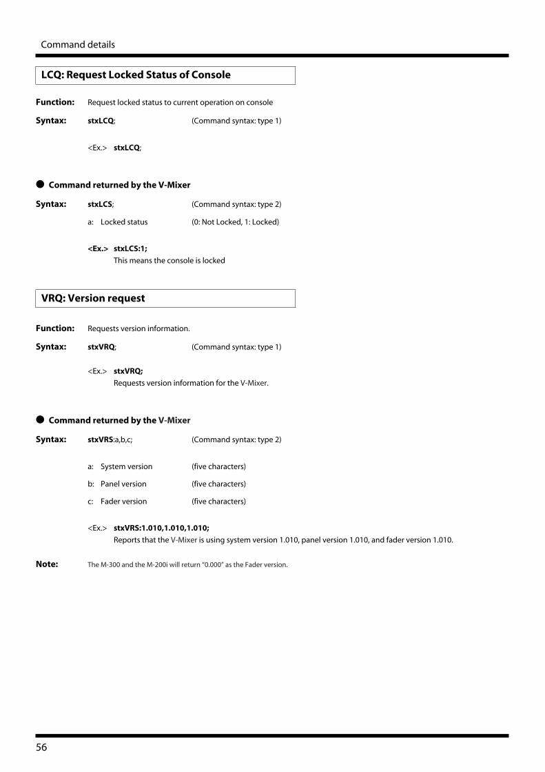
Syntax: stxLCQ; (Command syntax: type 1)
<Ex.> stxLCQ;
● Command returned by the V-Mixer
Syntax: stxLCS; (Command syntax: type 2)
a: Locked status (0: Not Locked, 1: Locked)
<Ex.> stxLCS:1;
This means the console is locked
Function: Requests version information.
Syntax: stxVRQ; (Command syntax: type 1)
<Ex.> stxVRQ;
Requests version information for the V-Mixer.
● Command returned by the V-Mixer
Syntax: stxVRS:a,b,c; (Command syntax: type 2)
a: System version (five characters)
b: Panel version (five characters)
c: Fader version (five characters)
<Ex.> stxVRS:1.010,1.010,1.010;
Reports that the V-Mixer is using system version 1.010, panel version 1.010, and fader version 1.010.
Note: The M-300 and the M-200i will return “0.000” as the Fader version.
LCQ: Request Locked Status of Console
VRQ: Version request
56
Page 57
Command details
Function: Requests status of REAC connection.
Syntax: stxRCQ: a; (Command syntax: type 2)
<Ex.> stxRCQ:A;
Requests REAC A port status.
● Command returned by the V-Mixer
Syntax: stxRCS:a,b; (Command syntax: type 2)
a: REAC port
A: REAC A
B: REAC B
b: Status
0: Not connected
1: Establishing the connection
2: Proper connection
<Ex.> stxRCS:A,2;
Reports that the REAC A port is properly connected.
Note: The reply command is automatically send when REAC connection status is altered.
• If you are using the M-200i, its REAC port is handled as REAC A port.
RCQ: REAC connection status request
57
Page 58
Command details
Function: Requests the display blackout status.
Syntax: stxBLQ: a; (Command syntax: type 1)
<Ex.> stxBLQ;
Requests the display blackout status.
● Command returned by the V-Mixer
Syntax: stxBLS:a; (Command syntax: type 2)
a: Blackout/cancel blackout (0: Cancel blackout, 1: Blackout)
<Ex.> stxBLS:1;
Outputs the display blackout.
Function: Requests the display brightness.
Syntax: stxDBQ: a; (Command syntax: type 1)
<Ex.> stxDBQ;
Requests the display brightness.
● Command returned by the V-Mixer
Syntax: stxDBS:a; (Command syntax: type 2)
a: Brightness(%) (0 to 100)
<Ex.> stxDBS:50;
Outputs the display brightness is 50%.
BLQ: Display blackout status request
DBQ: Display brightness request
58
Page 59
Command details
Function: Requests the display brightness.
Syntax: stxPBQ; (Command syntax: type 1)
<Ex.> stxPBQ;
Requests the display brightness.
● Command returned by the V-Mixer
Syntax: stxPBS:a; (Command syntax: type 2)
a: Brightness(%) (0 to 100)
<Ex.> stxPBS:50;
Outputs the panel brightness is 50%.
Function: Requests the lamp brightness.
Syntax: stxLBQ; (Command syntax: type 1)
<Ex.> stxLBQ;
Requests the lamp brightness.
● Command returned by the V-Mixer
Syntax: stxLBS:a; (Command syntax: type 1)
a: Brightness(%) (0 to 100)
<Ex.> stxLBS:50;
Outputs the lamp brightness is 50%.
PBQ: Panel brightness request
LBQ: Lamp brightness request
59
Page 60
Command details
Function: Requests the monitor dimmer on/off setting.
Syntax: stxDMQ; (Command syntax: type 1)
<Ex.> stxDMQ;
Requests the monitor dimmer on/off setting.
● Command returned by the V-Mixer
Syntax: stxDMS:a; (Command syntax: type 2)
a: On/off (0: Off, 1: On)
<Ex.> stxDMS:1;
Reports that the monitor dimmer is on.
DMQ: Monitor dimmer request
60
Page 61
Command details
Function: Requests status of USB memory recorder.
Syntax: stxRTQ; (Command syntax: type 1)
● Command returned by the V-Mixer
Syntax: stxRTS:a; (Command syntax: type 2)
a: Status
-1 Playback/Recording is not t possible (The USB memory is not inserted etc.)
0 Stop
1 Playing
2 Recording
3 Prepare for playback
4 Rec pause
<Ex.>
stxRTS:1;
Reports the song is in playing status.
Function:
Request for current position of USB memory recorder.
Syntax:
stxRLQ
; (Command syntax: type 1)
●
Command returned by the V-Mixer
Syntax:
stxRLS
:HHhMMmSSs; (Command syntax: type 2)
HH Hour
MM Minute
SS Second
<Ex.>
stxRLS:02m34s;
Reports that the current position is 02:34.
RTQ: USB memory recorder status request
RLQ: USB memory recorder current position request
61
Page 62
Command details
Function:
Request the song number currently selected, and the number of songs in the USB memory.
Syntax:
stxRIQ
; (Command syntax: type 1)
●
Command returned by the V-Mixer
Syntax:
stxRIS
:a,b; (Command syntax: type 2)
a: Current song number
b: Number of songs
<Ex.>
stxRIS:1,10;
Reports that song number 1 is selected and the number of songs in the USB memory is 10.
Function:
Request the song name.
Syntax:
stxRIQ
; (Command syntax: type 1)
stxRIQ
:a; (Command syntax: type 2)
a: Song number
<Ex.>
stxRNQ;
Request the song name currently selected.
<Ex.>
stxRNQ:1;
Requests the song name of song number 1.
●
Command returned by the V-Mixer
Syntax:
stxRNS
:a,b; (Command syntax: type 2)
a: Song number
b: Song name
<Ex.>
stxSNS:1,”SONG01.WAV”;
Output the songl name SONG01.WAV for the song number 1.
RIQ: Song number request
RNQ: Song name request
62
Page 63
Command details
Function:
Request the remaining amount of time that can be record to the USB memory.
Syntax:
stxRRQ
; (Command syntax: type 1)
●
Command returned by the V-Mixer
Syntax:
stxRRS
:HHhMMmSSs; (Command syntax: type 2)
HH Hour
MM Minute
SS Second
<Ex.>
stxRRS:01h02m34s;
Reports the remaining amount of time that can be record to the USB memory is 01:02:34.
RRQ: Recording remain time request
63
Page 64
Command details
Function:
Transmitted following successful reception.
Syntax:
ack (06H)
(Command syntax: type 0)
Note:
This “ack” may be omitted.
Function:
Transmitted when a problem occurred in the control computer in response to a command transmitted by the
V-Mixer.
Syntax:
stxERR
:a; (Command syntax: type 2)
a: Error number
0: When the signal from the V-Mixer could not be read.
If error number 0 is returned in response to a command sent by the V-Mixer in response to a Request
command, the V-Mixer will once again transmit the response to that Request command.
In the case of a command that has parameters, the V-Mixer will re-transmit the most recently
transmitted parameter.
Function:
Specifies whether transmission is possible. This is used for handshaking.
Syntax:
Xon (11H)
(transmission is possible) (Command syntax: type 0)
Xoff (13H)
(transmission is not possible) (Command syntax: type 0)
Commands transmitted from the control computer to the V-Mixer
ack (06H): Active reply
ERR: Error
Xon (11H) / Xoff (13H): Handshaking commands
64
Page 65
Command details
Function:
Transmitted following successful reception.
Syntax:
ack (06H)
(Command syntax: type 0)
Function:
Transmitted when a problem occurred in the V-Mixer in response to a command sent from the control
computer.
Syntax:
stxERR
:a; (Command syntax: type 2)
a: Error number
0: (Syntax error)
Transmitted when the command syntax was incorrect.
2: (Busy error)
The V-Mixer is busy and cannot process the command.
5: (Out of range error)
The parameter of the received command was out of range.
6: (Other error)
Some other error has occurred. This will be transmitted if the V-Mixer was unable to correctly process
the command.
Note:
If one of these commands occurs, the command that was sent to the
V-Mixer
immediately prior to this will be ignored.
Function:
Specifies whether transmission is possible. These are used for handshaking.
Syntax:
Xon
(11H)
(transmission is possible) (Command syntax: type 0)
Xoff
(13H)
(transmission is not possible) (Command syntax: type 0)
Commands transmitted from the V-Mixer to the control computer
ack (06H): Active reply
ERR: Error
Xon (11H) / Xoff (13H): Handshaking commands
65
Page 66
Command details
Function:
Transmitted when the V-Mixer is in error status.
Syntax:
stxERS
:a; (Command syntax: type 2)
a: Error number
0: Internal fan is stopped.
1: Lithium battery is low.
10: RS-232C frame rate error.
11: RS-232C parity error.
12: RS-232C receive buffer full error.
99: Abnormal stopping of the system.
Function:
Transmitted when the connected REAC devices is error status.
Syntax:
stxEPS
:a,b; (Command syntax: type 2)
a: REAC port
A: REAC A
B: REAC B
a: Error number
0: Internal fan is stopped.
1: Abnormal interior temperature.
2: Transmission error..
Note:
If you are using the M-200i, its REAC port is handled as REAC A port.
ERS: Error statuses of the V-Mixer
EPS: Error statuses of the connected REAC devices
66