16
ENGINEERING DOCUMENT 757-4002-311 VMX42 and VMX42_40 TOOL MACHINING CENTER TECHNICAL SPECIFICATIONS

ENGINEERING DOCUMENT
757-4002-311
VMX42 and VMX42_40 TOOL MACHINING CENTER TECHNICAL SPECIFICATIONS

CONFIDENTIAL / NOT FOR DISTRIBUTION page 2
1.0 Machine Capacity Table Working Surface 50” x 24” 1270mm x 610mm T-Slots 5 x 0.71” 5 x 18mm On 3.94” centers On 100mm centers Maximum Load With Uniform Distribution 3000 lb. 1360 kg Enclosure Door Opening 48” 1220mm Spindle Center To Column 27.6” 700mm Spindle Nose To Table Minimum/Maximum 6” / 30” 152mm / 762mm (For table and machine clearances, please see attachment “B”)
2.0 Spindle Type Cartridge, #40 Taper Speeds 0-10000 rpm Bearings ABEC Class 7 angular contact Bearing Lubrication Grease packed Spindle Motor AC Induction Motor, Dual winding, Fan cooled Spindle Drive 200VAC, 3 Phase, 50/60 Hz, Regenerative Braking Spindle Taper #40 Spindle HP-Peak (1 min. Rating) 24 HP (18 kW) -(15 min. Rating) 20HP (15 kW) -Continuous 15 HP (11 kW) Spindle Torque-Peak (1 min. Rating) 210 lb-ft (285 Nm) at 600 RPM -(15 min. Rating) 175 lb-ft (237 Nm) at 600 RPM -Continuous 105 lb-ft (142 Nm) at 750 RPM Drive Belt Ratio 1-1 Standard Belt Type 8mm pitch , Poly Chain Maximum Speed 10000 rpm Spindle Acceleration Time 0-10000 rpm in 6.5 seconds Spindle Decelerate Time 10000-0 rpm in 5.5 seconds Spindle Orientation Electronic - Spindle motor encoder Spindle Air Purge Standard (top and bottom) Spindle Air Blast Standard Spindle Configuration Cartridge-type, flange mounted (For spindle, see attachment “C”. For spindle Torque/HP, chart, see attachment “E”)

CONFIDENTIAL / NOT FOR DISTRIBUTION page 3
3.0 Movement and Ranges Longitudinal (X) axis 42” 1067mm Cross (Y) axis 24” 610mm Vertical (Z) axis 24” 610mm Floor to Table Surface 35” 889mm
4.0 Position/Feed Rates Rapid Traverse Rate: X axis 1181 inches per minute 30m/minute Y axis 1181 inches per minute 30m/minute Z axis 787 inches per minute 20m/minute Cutting Feed Rate: X axis 300 inches per minute 7.6m/minute Y axis 300 inches per minute 7.6m/minute Z axis 300 inches per minute 7.6m/minute Programming Resolution 0.0001” 0.002mm
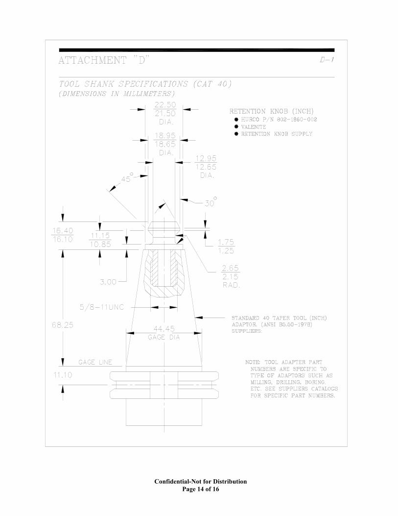
5.0 Automatic Tool Changer Number of Stations 24 Number of Stations (VMX42-40 Sta) 40 Maximum Tool Diameter 3.2” 80mm Maximum Tool Diameter (Adjacent Sides Empty) 4.72” 120mm Tool Pocket Pitch 3.2” 81mm Tool Pocket Pitch (VMX42-40 Sta) 3.0” 76.2 mm Maximum Tool Length 11.8” 300mm Maximum Tool Weight 15 lb. 7.0 kg Maximum Tool Weight in Magazine 180 lb. 82 kg. Tool Adapter ANSI Standard V-Flange ATC Time: Tool to tool next station 4 seconds Chip-to-Chip, 2000 rpm, 12” Z travel 9 seconds Tool Selection System Random pot, bi-directional, swing arm Retention Knob See attachment “D” Note: Tools to be loaded in the Automatic Tool Changer by using the spindle. Do not manually load tools directly into the Automatic Tool Changer. Tools must be loaded in correct orientation.

CONFIDENTIAL / NOT FOR DISTRIBUTION page 4
6.0 Axis Movement Axis Motors Torque: X AC Cont/Peak 74 lb-in/207 lb-in (8.36/23.4 Nm) Y AC Cont/Peak 102 lb-in/254 lb-in (11.5/28.7 Nm) Z AC Cont/Peak 252 lb-in/629 lb-in, with brake (28.5/71.1 Nm) Axis Thrust: Peak X 3159 lb. 14.05 kN Y 3446 lb. 15.33 kN Z 5332 lb. 23.72 kN Axis Trust: Continuous X 1130 lb. 5.02 kN Y 1384 lb. 6.15 kN Z 2137 lb. 9.50 kN Ball Screw Diameter X 1.57” 40mm Y 1.57” 40mm Z 1.57” 40mm Ball Screw Pitch X .63” 16mm Y .63” 16mm Z .63” 16mm Ball Screw Mounting X, Y and Z Double Nut Pre-Loaded Anchored on Both Ends, Pre-Stretched Ball Screw Drive System X 1.8:1 Ratio HTD belt driven Y 1.6:1 Ratio HTD belt driven Z Direct drive Encoder Drive motor mounted Guideway Systems: X Precision linear ball rails size 45 Y Precision linear ball rails size 45 Z Precision linear ball rails size 45 Bearing Trucks in X axis 4 total, 2 per rail Bearing Trucks in Y axis 4 total, 2 per rail Bearing Trucks in Z axis 4 total, 2 per rail Distance between X axis ways (centers) 13.4” 340mm Distance between Y axis ways (centers) 26.8” 680mm Distance across Z axis ways 17.8” 452mm (Telescoping way covers used over all exposed ways)

CONFIDENTIAL / NOT FOR DISTRIBUTION page 5
7.0 Accuracy (at 68o F) Positioning Accuracy (JIS B 6338) +/-0.0001” +/-0.0025mm Positioning Accuracy (10 Pass VDI - 3441 method) +/-0.0002” +/-0.005mm Repeatability (10 Pass VDI - 3441 method) +/-0.0001” +/-0.0025mm ( At final assembly, all machines are laser mapped, contour balanced with ball bar check, and run a capacity cutting test.. Therefore, the machine is capable of producing these accuracies. If at installation, the machine cannot achieve these accuracies, Hurco will determine the reason for non-attainment. If the reason is mechanical components, these will be replaced under the warranty. If the reason is improper transportation or rigging, the customer will be charged at normal service rates. )
8.0 Draw Bar Actuation Type Air/Oil Cylinder Stroke .43” ( 11mm) Maximum Force to Unclamp 5395-5845 lb. (24-26 kN) Air Supply 85-90 PSI (6 bar) Maximum Clamping Force 2473-2923 lb. (11-13 kN) Draw Bar Type Gripper fingers, Disc springs
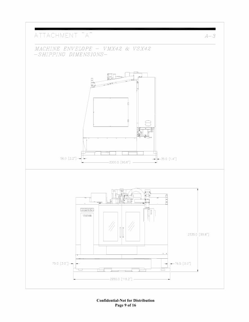
9.0 Machine Dimensions Shipping Dimensions Width 116” 2950mm Depth 90.6” 2300mm Height 99.8” 2535mm Operating Dimensions Width 182.4” 4632mm Depth [SSM] 133.2” 3382mm Depth [DSM] 147.1” 3735mm Height 105.6” 2683mm Machine Weight (approximate) 14080 lb. 6400 kg Machine Weight (VMX42-40 Sta) 14980 lb. 6800 kg Shipping Weight (approximate) 14960 lb. 6800 kg Shipping Weight (VMX42-40 Sta) 15880 lb. 7200 kg (See attachment “A” for machine envelope dimensions)
CONFIDENTIAL / NOT FOR DISTRIBUTION page 6
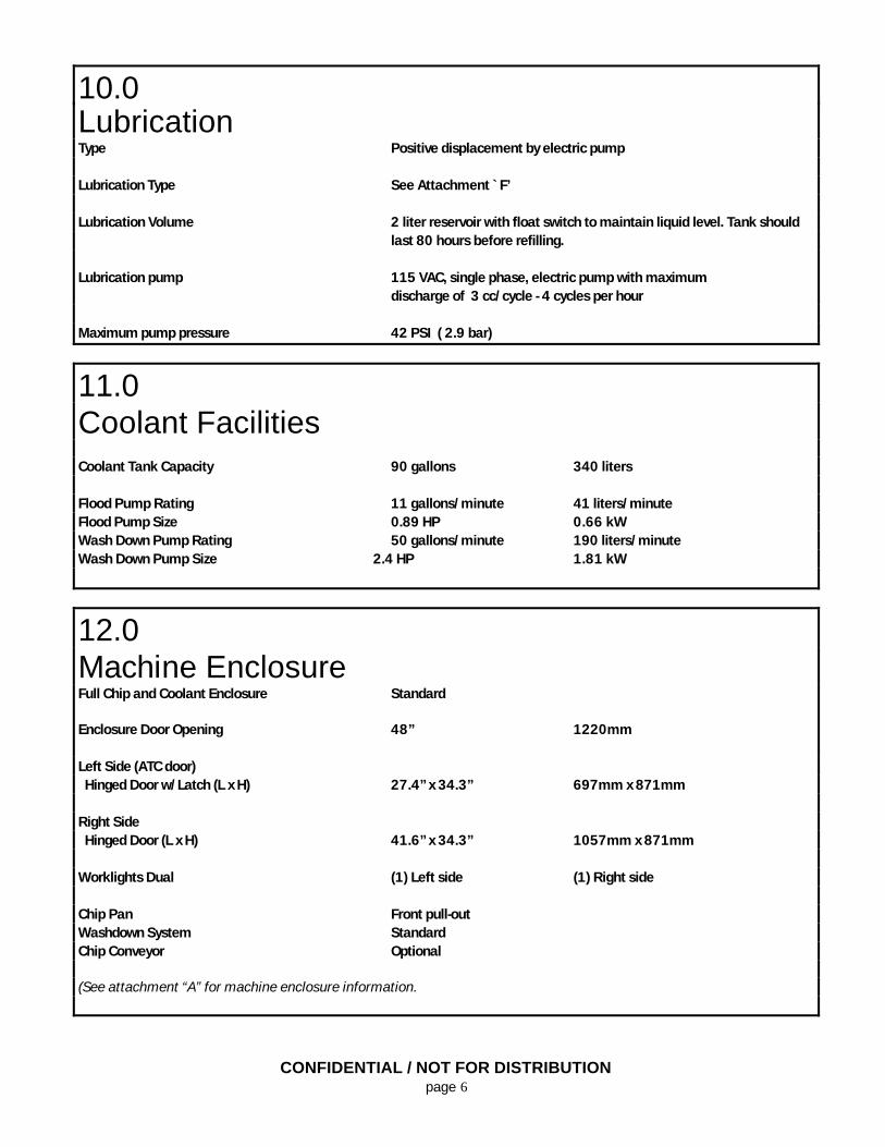
10.0 Lubrication Type Positive displacement by electric pump Lubrication Type See Attachment `F’ Lubrication Volume 2 liter reservoir with float switch to maintain liquid level. Tank should
last 80 hours before refilling. Lubrication pump 115 VAC, single phase, electric pump with maximum discharge of 3 cc/cycle - 4 cycles per hour Maximum pump pressure 42 PSI ( 2.9 bar)
11.0 Coolant Facilities Coolant Tank Capacity 90 gallons 340 liters Flood Pump Rating 11 gallons/minute 41 liters/minute Flood Pump Size 0.89 HP 0.66 kW Wash Down Pump Rating 50 gallons/minute 190 liters/minute Wash Down Pump Size 2.4 HP 1.81 kW
12.0 Machine Enclosure Full Chip and Coolant Enclosure Standard Enclosure Door Opening 48” 1220mm Left Side (ATC door) Hinged Door w/Latch (L x H) 27.4” x 34.3” 697mm x 871mm Right Side Hinged Door (L x H) 41.6” x 34.3” 1057mm x 871mm Worklights Dual (1) Left side (1) Right side Chip Pan Front pull-out Washdown System Standard Chip Conveyor Optional (See attachment “A” for machine enclosure information.

CONFIDENTIAL / NOT FOR DISTRIBUTION page 7
13.0 Service Requirements KVA Rating 38 Voltage Required 200-240 VAC / 60 Hz Air Requirements 5 CFM @ 80-100 psi 0.14 M3/min. @ 6-8 bar
IMPORTANT: As with all computer equipment, it is vital that the incoming power be free from high or low voltages, spikes, surges, and noise. The following are the extremes from normal constant RMS sinusoidal supply voltages the system can tolerate: Frequency.............................................................................47-63 Hz Impulse Voltage..................................................................200 percent peak voltage up to one msec duration. One (1) pulse per half cycle maximum. Voltage Drop........................................................................Reduction of 20 percent for one cycle or reduction of 50 percent per
half cycle. One (1) drop per second maximum. Deviation from constant voltage will not exceed ±10% of input voltage. Failure to provide required power parameters may affect warranty.
List of Attachments Machine Envelope __________________________Attachment A Table and Clearance ________________________Attachment B Spindle Assembly___________________________Attachment C Tool Holder and Retention Knob________________Attachment D Spindle Torque/HP Charts ____________________Attachment E Machine Oil Specifications ____________________Attachment F

Confidential-Not for Distribution Page 8 of 16
Confidential-Not for Distribution Page 9 of 16

Confidential-Not for Distribution Page 10 of 16

Confidential-Not for Distribution Page 11 of 16

Confidential-Not for Distribution Page 12 of 16

Confidential-Not for Distribution Page 13 of 16
Confidential-Not for Distribution Page 14 of 16

Confidential-Not for Distribution Page 15 of 16

Confidential-Not for Distribution Page 16 of 16
ATTACHMENT "E"
VMX42/40T−10K TORQUE/HORSEPOWER CHART
SPINDLE TORQUE/HORSEPOWER CHART


