83
VN1600 Interface Family Manual Version 4.1 | English

VN1600 Interface FamilyManual
Version 4.1 | English

Imprint
Vector InformatikGmbHIngersheimer Straße 24D-70499 Stuttgart
The information and data given in this user manual can be changed without prior notice. No part of this manual may be reproduced in anyform or by any means without the written permission of the publisher, regardless of which method or which instruments, electronic ormechanical, are used. All technical information, drafts, etc. are liable to law of copyright protection.
© Copyright 2017, Vector InformatikGmbH. All rights reserved.

Contents
VN1600 Interface Family Version 4.1 3
Contents
1 Introduction 51.1 About this User Manual 61.1.1 Certification 71.1.2 Warranty 71.1.3 Registered Trademarks 7
1.2 Important Notes 81.2.1 Safety Instructions and HazardWarnings 81.2.1.1 Proper Use and Intended Purpose 81.2.1.2 Hazards 91.2.1.3 Disclaimer 9
1.2.2 SEGGER emFile Module 9
2 VN1600 Interface Family 102.1 Introduction 11
2.2 Accessories 11
2.3 VN1610 122.3.1 Main Features 122.3.2 Connectors 122.3.3 Pin Assignment CH1 and CH2 132.3.4 Technical Data 13
2.4 VN1611 142.4.1 Main Features 142.4.2 Connectors 142.4.3 Pin Assignment CH1 and CH2 152.4.4 Technical Data 16
2.5 VN1630A 172.5.1 Main Features 172.5.2 Connectors Bus Side 172.5.3 Connectors USB Side 182.5.4 LEDs 192.5.5 Bus Configuration 202.5.6 Pin Assignment CH1/3 and CH2/4 232.5.7 Pin Assignment CH5 272.5.8 Replacing Piggybacks 292.5.9 Technical Data 32
2.6 VN1630 log 332.6.1 Main Features 332.6.2 Connectors Bus Side 342.6.3 Connectors USB Side 35

Contents
VN1600 Interface Family Version 4.1 4
2.6.4 LEDs 372.6.5 Bus Configuration 392.6.6 Pin Assignment CH1/3 and CH2/4 422.6.7 Pin Assignment CH5 452.6.8 Replacing Piggybacks 472.6.9 SD/SDHC Memory Cards 502.6.10 Ring Buffer in RAM 502.6.11 Real TimeClock 502.6.12 Battery 502.6.13 Beep 502.6.14 Technical Data 51
2.7 VN1640A 522.7.1 Main Features 522.7.2 Connectors Bus Side 522.7.3 Connectors USB Side 532.7.4 LEDs 542.7.5 Bus Configuration 552.7.6 Pin Assignment CH1...CH4 562.7.7 Pin Assignment CH5 572.7.8 Replacing Piggybacks 592.7.9 Technical Data 62
3 Getting Started 633.1 Driver Installation 64
3.2 Device Configuration 67
3.3 Quick Test 68
3.4 Loop Tests 693.4.1 CAN 69
4 Vector Hardware Configuration 714.1 General Information 72
4.2 Tool Description 734.2.1 Introduction 734.2.2 Tree View 74
5 Time Synchronization 775.1 General Information 78
5.2 Software Sync 80
5.3 Hardware Sync 81
VN1600 Interface Family Version 4.1 5
1 IntroductionIn this chapter you find the following information:
1.1 About this User Manual 61.1.1 Certification 71.1.2 Warranty 71.1.3 Registered Trademarks 7
1.2 Important Notes 81.2.1 Safety Instructions and HazardWarnings 81.2.2 SEGGER emFile Module 9

1.1 About this User Manual
VN1600 Interface Family Version 4.1 6
1.1 About this User ManualConventions In the two following charts you will find the conventions used in the user manual
regarding utilized spellings and symbols.
Style Utilizationbold Blocks, surface elements, window- and dialog names of the soft-
ware. Accentuation of warnings and advices.[OK]File|Save
Push buttons in bracketsNotation for menus andmenu entries
Microsoft Legally protected proper names and side notes.Source Code File name and source code.Hyperlink Hyperlinks and references.<CTRL>+<S> Notation for shortcuts.
Symbol UtilizationThis symbol calls your attention to warnings.
Here you can obtain supplemental information.
Here you can find additional information.
Here is an example that has been prepared for you.
Step-by-step instructions provide assistance at these points.
Instructions on editing files are found at these points.
This symbol warns you not to edit the specified file.

1.1 About this User Manual
VN1600 Interface Family Version 4.1 7
1.1.1 CertificationCertified QualityManagement System
Vector Informatik GmbH has ISO 9001:2008 certification. The ISO standard is a glob-ally recognized standard.
1.1.2 WarrantyRestrictionof warranty
We reserve the right to change the contents of the documentation and the softwarewithout notice. Vector Informatik GmbH assumes no liability for correct contents ordamages which are resulted from the usage of the documentation. We are grateful forreferences tomistakes or for suggestions for improvement to be able to offer youevenmore efficient products in the future.
1.1.3 Registered TrademarksRegisteredtrademarks
All trademarks mentioned in this documentation and if necessary third partyregistered are absolutely subject to the conditions of each valid label right and therights of particular registered proprietor. All trademarks, trade names or companynames are or can be trademarks or registered trademarks of their particular pro-prietors. All rights which are not expressly allowed are reserved. If an explicit label oftrademarks, which are used in this documentation, fails, should not mean that a nameis free of third party rights.
> Windows, Windows 7, Windows 8.1, Windows 10are trademarks of theMicrosoft Corporation.
> and are trademarks of the SD Card Association.

1.2 Important Notes
VN1600 Interface Family Version 4.1 8
1.2 Important Notes
1.2.1 Safety Instructions and Hazard Warnings
Caution!In order to avoid personal injuries and damage to property, you have to read andunderstand the following safety instructions and hazard warnings prior to installationand use of this interface. Keep this documentation (manual) always near the inter-face.
1.2.1.1 Proper Use and Intended Purpose
Caution!The interface is designed for analyzing, controlling and otherwise influencing controlsystems and electronic control units. This includes, inter alia, bus systems likeCAN, LIN, K-Line, MOST, FlexRay, Ethernet, BroadR-Reach and/or ARINC 429.
The interfacemay only be operated in a closed state. In particular, printed circuitsmust not be visible. The interfacemay only be operated (i) according to the instruc-tions and descriptions of this manual; (ii) with the electric power supply designed forthe interface, e.g. USB-powered power supply; and (iii) with accessories man-ufactured or approved by Vector.
The interface is exclusively designed for use by skilled personnel as its operationmay result in serious personal injuries and damage to property. Therefore, onlythose persons may operate the interface who (i) have understood the possibleeffects of the actions whichmay be caused by the interface; (ii) are specificallytrained in the handling with the interface, bus systems and the system intended tobe influenced; and (iii) have sufficient experience in using the interface safely.
The knowledge necessary for the operation of the interface can be acquired in work-shops and internal or external seminars offered by Vector. Additional and interfacespecific information, such as „Known Issues“, are available in the „Vector Know-ledgeBase“ on Vector´s website at www.vector.com. Please consult the „VectorKnowledgeBase“ for updated information prior to the operation of the interface.

1.2 Important Notes
VN1600 Interface Family Version 4.1 9
1.2.1.2 Hazards
Caution!The interfacemay control and/or otherwise influence the behavior of control sys-tems and electronic control units. Serious hazards for life, body and property mayarise, in particular, without limitation, by interventions in safety relevant systems(e.g. by deactivating or otherwisemanipulating the enginemanagement, steering,airbag and/or braking system) and/or if the interface is operated in public areas (e.g.public traffic, airspace). Therefore, youmust always ensure that the interface isused in a safemanner. This includes, inter alia, the ability to put the system inwhich the interface is used into a safe state at any time (e.g. by „emergency shut-down“), in particular, without limitation, in the event of errors or hazards.
Comply with all safety standards and public regulations which are relevant for theoperation of the system. Before you operate the system in public areas, it should betested on a site which is not accessible to the public and specifically prepared forperforming test drives in order to reduce hazards.
1.2.1.3 Disclaimer
Caution!Claims based on defects and liability claims against Vector are excluded to theextent damages or errors are caused by improper use of the interface or use notaccording to its intended purpose. The same applies to damages or errors arisingfrom insufficient training or lack of experience of personnel using the interface.
1.2.2 SEGGER emFile Module
Caution!The firmware of the VN1630 log contains the copyright protected emFile module ofSEGGER Microcontroller GmbH & Co. KG.
It should be noted that, in addition to the safety and hazard notes provided in sectionImportant Notes on page 8, the Licensing Terms of the Licensor expressly prohibitthe use of the SEGGER emFile module in weapons/weapons systems and/or theirdeployment in same. A “weapons system” is to be understood as meaning, in par-ticular, a system whose primary or material purpose is to injure, incapacitate or kill aperson or an opponent, or to destroy or damage the property of a person or an oppon-ent, or to threaten a person or an opponent, irrespective of whether the weapon orthe weapon system can be used to attack, defend, threaten or protect.

VN1600 Interface Family Version 4.1 10
2 VN1600 Interface FamilyIn this chapter you find the following information:
2.1 Introduction 11
2.2 Accessories 11
2.3 VN1610 12
2.4 VN1611 14
2.5 VN1630A 17
2.6 VN1630 log 33
2.7 VN1640A 52

2.1 Introduction
VN1600 Interface Family Version 4.1 11
2.1 IntroductionGeneralinformation
The VN1600 interface family is an advanced development of the proven CANcaseXL,which is a flexible and cost-efficient solution for CAN, LIN, K-Line and J1708 appli-cations. An excellent performance with minimal latency times and high time stampaccuracy is also guaranteed.
Themulti-application functionality of the VN1600 interface family supports sim-ultaneous operation of different applications on one channel, e. g. CANoe andCANape. Tasks range from simple bus analyses to complex remaining bus sim-ulations also diagnostic, calibration and reprogramming tasks as well as LIN 2.1 com-pliance tests. You can also program your own applications using the XL DriverLibrary.
Bus types Depending on the VN1600 interface, built-in transceivers as well as exchangeableCAN/LIN and J1708 transceivers can be used. The exchangeable transceivers areavailable as plug-in boards (Piggybacks) and are inserted in the VN1600. A list of com-patible Piggybacks can be found in the accessories manual on the Vector Driver Disk.
Figure 1: Piggyback
2.2 AccessoriesReferenceInformation on available accessories can be found in the separate accessoriesmanual on the Vector Driver Disk in \Documentation\Accessories.

2.3 VN1610
VN1600 Interface Family Version 4.1 12
2.3 VN1610
2.3.1 Main FeaturesVN1610 features Themain features of the VN1610 interface are:
> 2x CAN high-speed 1051cap transceiver (capacitively decoupled)
> Software sync
Figure 2: VN1610 CAN Interface
2.3.2 Connectors> D-SUB9 (CH1/2)
The VN1610 has a D-SUB9 connector with two CAN channels. Further inform-ation on the pin assignment for CH1/CH2 can be found in section Pin AssignmentCH1 and CH2 on page 13.
> USBConnect your PC and the VN1610 via USB to install and to use the device withmeasurement applications (e. g. CANoe, CANalyzer).

2.3 VN1610
VN1600 Interface Family Version 4.1 13
2.3.3 Pin Assignment CH1 and CH2D-SUB9 connector The pin assignment of the D-SUB9 connector (CH1 and CH2) is as follows:
CH1/CH25
4
3
2
16
7
8
9Shield
1051cap CAN Low1051cap CAN High
1051cap GND
1051cap CAN Low
1051cap CAN Low1051cap GND
1051cap CAN High
Shield
CH1 CH2
CAN Y cable Use the CANcable 2Y to access both channels on separate D-SUB9 connectors (seeaccessories manual, part number 05075).
CAN0Low2 2
GND3 3
CAN0High7 7
(CAN0Low0of0CH2)4 4
CAN0Low01 2
GND06 3
CAN0High08 7
Shield5 5
Shield5 5
-9 9
VN1610CH1/2
CH10(A)
CH20(B)
Figure 3: CANcable 2Y connected to VN1610
2.3.4 Technical Data
CAN channels 2x CAN high-speed 1051capCAN: up to 2Mbit/sCAN FD: up to 8Mbit/s
Temperature range Operating: -40 °C...+70 °CShipping and storage: -40 °C...+85 °C
Relative humidity of ambient air 15%...95%, non-condensingDimensions (LxWxH) 65mm x 42mm x 20mmWeight 80 gOperating system requirements Windows 7 SP1 (32 bit / 64 bit)
Windows 8.1 (32 bit / 64 bit)Windows 10 (64 bit)

2.4 VN1611
VN1600 Interface Family Version 4.1 14
2.4 VN1611
2.4.1 Main FeaturesVN1611 features Themain features of the VN1611 interface are:
> 1x LIN 7269cap transceiver (capacitively decoupled)
> 1x CAN high-speed 1051cap transceiver (capacitively decoupled)
> Software sync
Figure 4: VN1611 LIN/CAN Interface
NoteThe VN1611 does not support LIN2.1 compliance tests. Please use the VN1630Aor the VN1640A for these purposes.
2.4.2 Connectors> D-SUB9 (CH1/2)
The VN1611 has a D-SUB9 connector with one LIN and one CAN channel. Fur-ther information on the pin assignment for CH1/CH2 can be found in section PinAssignment CH1 and CH2 on page 15.
> USBConnect your PC and the VN1611 via USB to install and to use the device withmeasurement applications (e. g. CANoe, CANalyzer).

2.4 VN1611
VN1600 Interface Family Version 4.1 15
2.4.3 Pin Assignment CH1 and CH2D-SUB9 connector The pin assignment of the D-SUB9 connector (CH1 and CH2) is as follows:
CH1/CH25
4
3
2
16
7
8
9Shield
7269capoPdis1051capoCANoHigh
7269capoVB-
1051capoCANoLow1051capoGND
7269capoLIN
Shield
CH1 CH2
7269capoVB+
Pdis: power disable
CAN/LIN Y cable Use the CANcable 2Y to access both channels on separate D-SUB9 connectors (seeaccessories manual, part number 05075).
-2 2
VB-3 3
LIN7 7
PdisH/powerHdisable)4 4
CANHLowH1 2
GNDH6 3
CANHHighH8 7
Shield5 5
Shield5 5
VB+9 9
VN1611CH1/2
CH1H/A)
CH2H/B)
Figure 5: CANcable 2Y connected to VN1611
NoteIf pin 4 (Pdis) is connected to pin 3 (VB-), the internal power supply is disabled. Inthis case an external power supply is required at pin 9 (VB+).

2.4 VN1611
VN1600 Interface Family Version 4.1 16
2.4.4 Technical Data
CAN channels 1x CAN high-speed 1051capCAN: up to 2Mbit/sCAN FD: up to 8Mbit/s
LIN channels 1x LIN 7269capup to 330 kbit/s
K-Line channels 1Temperature range Operating: -40 °C...+70 °C
Shipping and storage: -40 °C...+85 °CRelative humidity of ambient air 15%...95%, non-condensingDimensions (LxWxH) 65mm x 42mm x 20mmWeight 80 gOperating system requirements Windows 7 SP1 (32 bit / 64 bit)
Windows 8.1 (32 bit / 64 bit)Windows 10 (64 bit)

2.5 VN1630A
VN1600 Interface Family Version 4.1 17
2.5 VN1630A
2.5.1 Main FeaturesVN1630A features Themain features of the VN1630A interface are:
> 2x CAN high-speed 1051cap transceiver (capacitively decoupled)
> 2x additional plug-in location for CAN-/LINpiggies
> Fifth channel for dedicated digital-analog input/output tasks
> Five LEDs indicating bus activities and status
> Software sync
> Hardware sync (via SYNCcableXL)
Figure 6: VN1630ACAN/LIN Interface
2.5.2 Connectors Bus SideDevice connectors
Figure 7: VN1630Awith syncand D-SUB9 connectors
> Binder connector (Sync)This connector (Binder type 711) can be used for time synchronization of differentVector devices (see section Time Synchronization on page 77). The sync con-nector is not intended to connect a power supply.Pin Assignment1 Not connected2 Synchronization line3 Ground
312

2.5 VN1630A
VN1600 Interface Family Version 4.1 18
> D-SUB9 (CH1/3 and CH2/4)The VN1630A has two D-SUB9 connectors, each with up to two channels(CAN/CAN or LIN/CAN). Further information on the pin assignment for CH1/CH3and CH2/CH4 can be found in section Pin Assignment CH1/3 and CH2/4 on page23.
2.5.3 Connectors USB SideDevice connectors
Figure 8: VN1630Awith USBand D-SUB9 connector
> USBConnect your PC and the VN1630A via USB to install and to use the device withmeasurement applications (e. g. CANoe, CANalyzer). Use the USB2.0 compliantcable found in the delivery (USB extension cables may generate faults betweenthe PC and the device). Connect the device directly to USB at your PC or use aUSB hub with its own power supply (self-powered). Depending on the used Piggy-back, the VN1630A requires the entire USB current (500mA) which cannot beprovided by a bus-powered USB hub.
> D-SUB9 (CH5)The VN1630A has a D-SUB9 connector (CH5) for dedicated digital-analoginput/output tasks. The pin assignment can be found in section Pin AssignmentCH5 on page 27.

2.5 VN1630A
VN1600 Interface Family Version 4.1 19
2.5.4 LEDsDescription The VN1630A has five LEDs indicating bus activities and status:
Figure 9: LEDsof the VN1630A
> CH1 … CH4 (with CAN-/LINpiggies)Multicolored channel LEDs, each indicating the bus activity for CAN, LIN or K-Line.Color DescriptionGreen Data frames have been sent or received correctly.Orange CAN: Error frames have been sent or received.
LIN/K-Line: Protocol errors as well as valid messages on the bus.Red CAN: Bus off.
LIN/K-Line: Protocol errors on the bus.CAN: The flashing frequencydependson the bus load.
> StatusMulticolored LED that indicates the status of the device.Color DescriptionGreen Device is ready for operation/runningmeasurement.Orange Initializing driver. Please wait.Red Error. Device not working.

2.5 VN1630A
VN1600 Interface Family Version 4.1 20
2.5.5 Bus ConfigurationPiggybacks forCH1 and CH2
An advantage of the VN1630A is its two Piggyback plug-in locations (primary chan-nels CH1 and CH2). Depending on requirements, electrically decoupled CAN High-Speed, CAN Low-Speed, CAN SingleWire, J1708 or LIN transceivers may be used.In addition, two electrically decoupled built-in CAN TJA1051 (high-speed) trans-ceivers are available (secondary channels CH3 and CH4). CH5 is reserved for ded-icated IO tasks.
Piggy 1(CH1)
Piggy 2(CH2)
Figure 10: Piggybackplug-in locations for CH1 and CH2
NoteLINpiggies have to be inserted before CANpiggies (in ascending order). If youintend to use only one LINpiggy, please use the first plug-in location (CH1). J1708should be handled like CAN.
Each empty plug-in location is loaded with a built-in transceiver from the secondarychannel according to the DIP switch settings.
ReferenceFurther information on DIP switches can be found in section Pin Assignment CH1/3and CH2/4 on page 23.

2.5 VN1630A
VN1600 Interface Family Version 4.1 21
Piggybackorder Primary CH1 CH2
Piggyback
LIN1
or
CAN2
LIN2
or
CAN1
Secondary CH3 CH4Built-inTransceiver
CAN1051cap
CAN1051cap
Examples The following tables show examples of possible configurations:
2x CAN withoutPiggybacks1x IO CH1/CH3 CH2/CH4 CH5
Piggyback - - -Primary CH1 CH2 CH5
Ç ÇBuilt-inTransceiver
CAN1051cap
CAN1051cap
Secondary CH3 CH4
ConfigurationCH1: no Piggyback, built-in CAN 1051cap transceiver (CH3).CH3: not usable.CH2: no Piggyback, built-in CAN 1051cap transceiver (CH4).CH4: not usable.CH5: on-board IO.
4x CAN1x IO
CH1/CH3 CH2/CH4 CH5Piggyback CAN CAN -Primary CH1 CH2 CH5
- -Built-inTransceiver
CAN1051cap
CAN1051cap
Secondary CH3 CH4
ConfigurationCH1: CANpiggy.CH3: built-in CAN 1051cap transceiver.CH2: CANpiggy.CH4: built-in CAN 1051cap transceiver.CH5: on-board IO.

2.5 VN1630A
VN1600 Interface Family Version 4.1 22
1x LIN2x CAN1x IO CH1/CH3 CH2/CH4 CH5
Piggyback LIN - -Primary CH1 CH2 CH5
- ÇBuilt-inTransceiver
CAN1051cap
CAN1051cap
Secondary CH3 CH4
ConfigurationCH1: LINpiggy.CH3: built-in CAN 1051cap transceiver.CH2: no Piggyback, built-in CAN 1051cap transceiver (CH4).CH4: not usable.CH5: on-board IO.

2.5 VN1630A
VN1600 Interface Family Version 4.1 23
2.5.6 Pin Assignment CH1/3 and CH2/4Double assignment ofD-SUB9 connectorsCH1 and CH2
Before installing a Piggyback in the plug-in location (see section Replacing Piggy-backs on page 29), the pin assignment of the D-SUB9 connector (CH1/CH3 andCH2/CH4) has to be selected via DIP switches, which can be found inside the deviceat the plug-in locations.
Piggy 1 (CH1/3) Piggy 2 (CH2/4)
Figure 11: DIP switches (left: CH1/3, right: CH2/4)
Pin assignmentCH1…CH4
The pin assignments of the D-SUB9 connectors depend on the used bus transceiverconfiguration inside the VN1630A. A list of available Piggybacks and their D-SUB9pin assignments is included in the separate accessories manual.
> No Piggyback insertedIf no Piggyback is inserted, only thebuilt-in CAN transceiver at CH1 (CH2)is active (no double assignment of theD-SUB9 connector):
Pin Assignment1 Not connected2 1051cap CAN Low3 GND4 Not connected5 Shield6 Not connected7 1051cap CAN High8 Not connected9 Not connected
A: all ‚OFF’ / B: all ‚ON’
A B
16
ON
1 6
ON
Figure 12: Configuration without Piggyback

2.5 VN1630A
VN1600 Interface Family Version 4.1 24
ExampleNo PiggybackThe following example shows the pin assignment of CH1/CH3 if no Piggyback isinserted in the plug-in location at channel 1.
5
4
3
2
16
7
8
9Shield
1051capbGND
1051capbCANbLow1051capbCANbHigh
disabled
CH1 CH3
> CAN/LIN Piggyback insertedIf a CAN- or LINpiggy is inserted, thePiggyback is assigned to CH1 (CH2)and the built-in CAN transceiver isassigned to CH3 (CH4):
Pin Assignment1 1051cap CAN Low2 Piggyback-dependent3 Piggyback-dependent4 Piggyback-dependent5 Shield6 GND7 Piggyback-dependent8 1051cap CAN High9 Piggyback-dependent
A: all ‚ON’ / B: all ‚OFF’
1 6
ON
16
ON
A B
Figure 13: Configuration with Piggyback
ExampleCANpiggy 1041magThe following example shows the pin assignment of CH1/CH3 if a CANpiggy1041mag is inserted in the plug-in location at channel 1.
5
4
3
2
16
7
8
9Shield
1041magLVB+1041magLSplit
1051capLCANLHigh1041magLVB-
1041magLCANLLow
1051capLCANLLow1051capLGND
1041magLCANLHigh
Shield
CH1 CH3

2.5 VN1630A
VN1600 Interface Family Version 4.1 25
NoteThe described pin assignment is also valid for CH2/CH4. A warningmessageappears inVector Hardware Config if the DIP switch settings are improperly set.Check your DIP switch settings in this case.

2.5 VN1630A
VN1600 Interface Family Version 4.1 26
CAN/LIN Y cable Use the CANcable 2Y to access both channels on separate D-SUB9 connectors (seeaccessories manual, part number 05075). The pin assignments of the D-SUB9 con-nectors depend on the used bus transceiver configuration inside the VN1630A. A listof available Piggybacks and their D-SUB9 pin assignments is included in theaccessories manual.
CAN4Low2 2
GND4/4VB-3 3
CAN4High4/4LIN7 7
Special4function4 4
CAN4Low41 2
GND46 3
CAN4High48 7
Shield5 5
Shield5 5
)VB+99 9
CAN4Low2 2
GND4/4VB-3 3
CAN4High4/4LIN7 7
Special4function4 4
CAN4Low41 2
GND46 3
CAN4High48 7
Shield5 5
Shield5 5
)VB+99 9
CH14)A9
CH34)B9
CH24)A9
CH44)B9
VN1630ACH1/3
VN1630ACH2/4
Figure 14: 2xCANcable 2Y connected to VN1630A

2.5 VN1630A
VN1600 Interface Family Version 4.1 27
2.5.7 Pin Assignment CH5Digital/analog IO The pin assignment for CH5 is
as follows:Pin Assignment1 Analog input2 Not connected3 Not connected4 Digital input 05 Digital input 16 Analog GND7 Not connected8 Digital output9 Digital GND
1
Analog GND1
2
3
4
59
8
7
66
Digital In 0
5
Digital Out
Digital GND
Analog In
4
Digital In 1
8
9
Internalinterconnection ofdigital input 0/1
To Processor
Digital GND
Vcc
Digital GND Digital GND
Digital Input 0/1
Isolation
20k
Vref
200k
OUT
IN-
IN+
33 V370 pF
Figure 15: Digital input 0/1
Internalinterconnection ofdigital output
From Processor
Digital Output
Digital GND
Isolation
33 V 370 pF
Figure 16: Digital output
Internalinterconnection ofanalog input
To Processor
Analog GND
Vcc
Analog Input
100k
1M
33 V370 pF
Analog GND
22 pFADC
15k
10k
Analog GND
OUT
IN+
IN-
Isolation
INOUT
Figure 17: Analog input

2.5 VN1630A
VN1600 Interface Family Version 4.1 28
Extendedmeasuringrange of the analoginput
In normal operation, voltages up to 18 V can be applied andmeasured at the analoginput. The cutoff frequency fc (-3 dB) for AC voltages is approx. 7.2 kHz.
For measurements above 18 V (max. 50 V), an external series resistor has to beapplied to the analog input. The series resistor Rext depends on the input voltageUinput and can be calculated as follows:
The cutoff frequency for AC voltages is also affected by the external series resistor:
Examples 24 V 32 V 36 V 48 VRext 367 kΩ 856 kΩ 1100 kΩ 1833 kΩRext (E96) 374 kΩ
(24.12 V)866 kΩ(32.17 V)
1100 kΩ(36.00 V)
1870 kΩ(48.60 V)
fc (-3 dB) 1148 Hz 496 Hz 390 Hz 230 Hz

2.5 VN1630A
VN1600 Interface Family Version 4.1 29
2.5.8 Replacing Piggybacks
Caution!When performing this operation be sure not to touch the top or bottom of the boards(VN1630A main board or Piggybacks) to avoid damages due to electrical dis-charges.
Step by Step Procedure1. First, loosen the VN1630A housing screws on the side with the two D-SUB9
connectors. This requires removing the two black decorative caps. Then care-fully pull the PC-board out of the housing.
Figure 18: Opening the housing
2. You will find the plug-in location 1 (CH1) at the sync connector side and plug-inlocation 2 (CH2) at the edge of the PC-board.
Piggy 1(CH1)
Piggy 2(CH2)
Figure 19: Piggybackplug-in locationsCH1 and CH2

2.5 VN1630A
VN1600 Interface Family Version 4.1 30
3. Each Piggyback is fastened by a screw and retainer. Please loosen the appro-priate screw including the retainer and carefully remove the Piggyback from theplug-in location.
CH2
CH1
Figure 20: Unmount/mount Piggybacks
4. Set the DIP switches as described in section Pin Assignment CH1/3 andCH2/4 on page 23.
5. Insert the replacement Piggyback. When doing this pleasemake sure that thesingle and dual-row connectors are not laterally offset.
6. Secure the new Piggyback with the appropriate screw and retainer.

2.5 VN1630A
VN1600 Interface Family Version 4.1 31
7. Place the VN1630A main board back in the housing. This operation involves pla-cing the housing on a table with its back side (side with the bar code) facingupward. Then themain board with the Piggybacks facing upward is insertedinto the second guide rails.
Figure 21: Second guide rails
8. It should be possible to slide themain board in the housing up to a few mil-limeters from the end without forcing it in. Close the housing by applying lightpressure and then secure it with the appropriate screw fasteners. The screwsshould be secure but not excessively tight.
9. Please also attach the two black decorative caps.
10. Connect the VN1630A and the PC via the USB cable and check the bus con-figuration inVector Hardware Config.
Figure 22: Check inserted Piggybacks

2.5 VN1630A
VN1600 Interface Family Version 4.1 32
2.5.9 Technical Data
CAN channels Max. 42x CAN high-speed 1051cap2x configurable via PiggybacksCAN: up to 2Mbit/sCAN FD: up to 8Mbit/s
LIN channels Max. 2configurable via Piggybacksup to 330 kbit/s
K-Line channels Max. 2with LINpiggy 7269mag at CH1/CH2
J1708 channels Max. 2configurable via Piggybacks
Analog input 10 bitInput 0 V...18 VVoltage tolerance up to 50 V(with series resistor)Sampling rate up to 1 kHz
Digital input Range 0 V...32 VSchmitt trigger high 2.7 V, low 2.2 VHysteresis 0.5 VInput frequencies up to 1 kHz
Digital output OpenDrainExternal supply up to 32 VCurrent max. 500mAShort circuit / over voltage protected
Power consumption Approx. 2.5WTemperature range Operating: -40 °C...+70 °C
Shipping and storage: -40 °C...+85 °CRelative humidity of ambient air 15%...95%, non-condensingDimensions (LxWxH) Approx. 90mm x 110mm x 35mmWeight 230 g (without accessories)Operating system requirements Windows 7 SP1 (32 bit / 64 bit)
Windows 8.1 (32 bit / 64 bit)Windows 10 (64 bit)

2.6 VN1630 log
VN1600 Interface Family Version 4.1 33
2.6 VN1630 log
2.6.1 Main FeaturesVN1630 log features Themain features of the VN1630 log interface are:
> 2x CAN high-speed 1051cap transceiver (capacitively decoupled)
> 2x additional plug-in location for CAN-/LINpiggies
> Fifth channel for dedicated digital-analog input/output tasks
> LEDs indicating bus activities and status
> Software sync
> Hardware sync (via SYNCcableXL)
The recording features are:
> Recording data of CAN, CAN FD, LIN, digital and analog inputs
> Data storage on SD/SDHC card
> Separate LED for logging status
> Filter and Trigger symbolically configurable
> Real time clock for date/time information
> External power supply for standalonemode
Figure 23: VN1630 log CAN/LIN Interface

2.6 VN1630 log
VN1600 Interface Family Version 4.1 34
2.6.2 Connectors Bus SideDevice connectors
Figure 24: VN1630 log with syncand D-SUB9 connectors
> Power/hardware sync connectorThe VN1630 log has two identical power/sync connectors (Binder type 711) whichcan be used for power or in InterfaceMode for time synchronization of differentVector devices (see section Time Synchronization on page 77). It does not matterwhich connector is used to supply the device.Pin Assignment1 Power supply (typ. 12 V)2 Synchronization line (for InterfaceMode)3 Ground
312
> D-SUB9 (CH1/3 and CH2/4)The VN1630 log has two D-SUB9 connectors, each with up to two channels(CAN/CAN or LIN/CAN). Further information on the pin assignment for CH1/CH3and CH2/CH4 can be found in section Pin Assignment CH1/3 and CH2/4 on page42.
Caution!It is recommended to connect the VN1630 log to the same voltage supply (e. g. bat-tery of the vehicle) as the vehicle or test equipment. If two different voltage suppliesare being used for the VN1630 log and the test equipment, the ground (GND) pins ofthe two voltage supplies must be connected.

2.6 VN1630 log
VN1600 Interface Family Version 4.1 35
2.6.3 Connectors USB SideDevice connectors
Figure 25: VN1630 log with SD card slot, LED push-button, USBand D-SUB9 connector
> SD card slotThe VN1630 log has a push-and-pull card holder in which the SD card is insertedand removed. To insert a SD card push it until it latches in place securely. Tosecurely remove the SD card, press the LED push button at least for threeseconds. Remaining data in the ring buffer is copied to the SD card which can takeapprox. 15 seconds. During this time, the LED flashes yellow. Remove the SDcard only if the LED lights green. During this sequence the VN1630 logmust notbe disconnected from the power supply. This protects the SD card frommemorylosses. Then unlatch the SD card by pushing it into the holder slot. Remove thecard.
Caution!To avoidmechanical damage do not pull the SD card from the card holder force-fully.
> LED push buttonLED that indicates the SD card status.Color DescriptionGreen SD card can be removed.Yellow On: SD card inserted and identified. Do not remove the SD card.
Flashing: Logging in progress. Do not remove the SD card.
> USBConnect your PC and the VN1630 log via USB to install, to configure and to usethe device with measurement applications (e. g. CANoe, CANalyzer). Use theUSB2.0 compliant cable found in the delivery (USB extension cables may gen-erate faults between the PC and the device). Connect the device directly to USBat your PC or use a USB hub with its own power supply (self-powered). Dependingon the used Piggyback, the VN1630 log requires the entire USB current (500mA)which cannot be provided by a bus-powered USB hub. The VN1630 log also sup-ports two operatingmodes which can be switched by using the USB connectionand power supply respectively:
Mode USB External Power SupplyInterfaceMode/
Logging configurationconnected to PC optional
LoggingMode not connected yes

2.6 VN1630 log
VN1600 Interface Family Version 4.1 36
InterfaceMode In InterfaceMode, the VN1630 log operates as a CAN/LIN interface between a PCand the bus. Messages can be received and sent over both channels with suitabletools (identical to VN1630A). The VN1630 logmust be in the InterfaceMode to con-figure the loggingmode.
While used as interface by a Vector tool, recorded data can be read from the SD card.In this case the interface functionality has priority and the card access takes placeswith reduced speed.
LoggingMode The LoggingMode enables the PC independent usage of the VN1630 log and allowsthe logging of CAN and LIN events. For this purpose, the VN1630 logmust beunplugged from the USB connector of the PC and externally supplied via the Binderconnector.
Caution!During logging, the VN1630 logmust not be connected to the PC via the USBcable, since the loggingmode would otherwise be exited!
ReferenceInformation on the configuration of the loggingmode can be found in the separatemanual provided with theVector Logger Configurator on the Vector Driver Disk in\Tools\VN1630_log.
> D-SUB9 (CH5)The VN1630 log has a D-SUB9 connector (CH5) for dedicated digital-analoginput/output tasks. The pin assignment can be found in section Pin AssignmentCH5 on page 45.

2.6 VN1630 log
VN1600 Interface Family Version 4.1 37
2.6.4 LEDsDescription The VN1630 log has five LEDs indicating bus activities and status as well one LED
for LoggingMode.
Figure 26: LEDsof the VN1630 log
> LogMulticolored LED that indicates the status of the loggingmode.Color DescriptionGreen Device is accessing the SD card.Orange On: SD card full.
Flashing: Error while accessing SD card.Red Flashing (1 Hz): Piggyback equipment not compatible with logging con-
figuration.Flashing (>1 Hz): Error while logging.
> CH1 … CH4 (with CAN-/LINpiggies)Multicolored channel LEDs, each indicating the bus activity for CAN, LIN or K-Line.Color DescriptionGreen Data frames have been sent or received correctly.Orange CAN: Error frames have been sent or received.
LIN/K-Line: Protocol errors as well as valid messages on the bus.Red CAN: Bus off.
LIN/K-Line: Protocol errors on the bus.CAN: The flashing frequencydependson the bus load.
> Status (Interface Mode)Multicolored LED that indicates the status of the device.Color DescriptionGreen Device is ready for operation/runningmeasurement.Orange Initializing driver. Please wait.Red Error. Device not working.

2.6 VN1630 log
VN1600 Interface Family Version 4.1 38
> Status (Logging Mode)Multicolored LED that indicates the status of the device.Color DescriptionGreen Device is ready for operation and logging configuration is started.Orange Flashing (slow): SD card not inserted.
Flashing (fast): Firmware update in progress.Red Error.
Flashing (slow): Device not working or logging firmwaremissing.Flashing (fast): Logging configurationmissing on SD card or incom-patible with firmware.
2.6 VN1630 log
VN1600 Interface Family Version 4.1 39
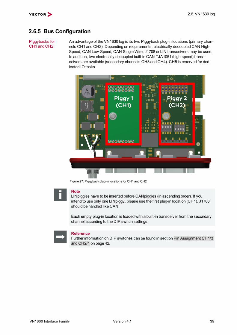
2.6.5 Bus ConfigurationPiggybacks forCH1 and CH2
An advantage of the VN1630 log is its two Piggyback plug-in locations (primary chan-nels CH1 and CH2). Depending on requirements, electrically decoupled CAN High-Speed, CAN Low-Speed, CAN SingleWire, J1708 or LIN transceivers may be used.In addition, two electrically decoupled built-in CAN TJA1051 (high-speed) trans-ceivers are available (secondary channels CH3 and CH4). CH5 is reserved for ded-icated IO tasks.
Piggy 1(CH1)
Piggy 2(CH2)
Figure 27: Piggybackplug-in locations for CH1 and CH2
NoteLINpiggies have to be inserted before CANpiggies (in ascending order). If youintend to use only one LINpiggy, please use the first plug-in location (CH1). J1708should be handled like CAN.
Each empty plug-in location is loaded with a built-in transceiver from the secondarychannel according to the DIP switch settings.
ReferenceFurther information on DIP switches can be found in section Pin Assignment CH1/3and CH2/4 on page 42.

2.6 VN1630 log
VN1600 Interface Family Version 4.1 40
Piggybackorder Primary CH1 CH2
Piggyback
LIN1
or
CAN2
LIN2
or
CAN1
Secondary CH3 CH4Built-inTransceiver
CAN1051cap
CAN1051cap
Examples The following tables show examples of possible configurations:
2x CAN withoutPiggybacks1x IO CH1/CH3 CH2/CH4 CH5
Piggyback - - -Primary CH1 CH2 CH5
Ç ÇBuilt-inTransceiver
CAN1051cap
CAN1051cap
Secondary CH3 CH4
ConfigurationCH1: no Piggyback, built-in CAN 1051cap transceiver (CH3).CH3: not usable.CH2: no Piggyback, built-in CAN 1051cap transceiver (CH4).CH4: not usable.CH5: on-board IO.
4x CAN1x IO
CH1/CH3 CH2/CH4 CH5Piggyback CAN CAN -Primary CH1 CH2 CH5
- -Built-inTransceiver
CAN1051cap
CAN1051cap
Secondary CH3 CH4
ConfigurationCH1: CANpiggy.CH3: built-in CAN 1051cap transceiver.CH2: CANpiggy.CH4: built-in CAN 1051cap transceiver.CH5: on-board IO.

2.6 VN1630 log
VN1600 Interface Family Version 4.1 41
1x LIN2x CAN1x IO CH1/CH3 CH2/CH4 CH5
Piggyback LIN - -Primary CH1 CH2 CH5
- ÇBuilt-inTransceiver
CAN1051cap
CAN1051cap
Secondary CH3 CH4
ConfigurationCH1: LINpiggy.CH3: built-in CAN 1051cap transceiver.CH2: no Piggyback, built-in CAN 1051cap transceiver (CH4).CH4: not usable.CH5: on-board IO.

2.6 VN1630 log
VN1600 Interface Family Version 4.1 42
2.6.6 Pin Assignment CH1/3 and CH2/4Double assignment ofD-SUB9 connectorsCH1 and CH2
Before installing a Piggyback in the plug-in location (see section Replacing Piggy-backs on page 47), the pin assignment of the D-SUB9 connector (CH1/CH3 andCH2/CH4) has to be selected via DIP switches, which can be found inside the deviceat the plug-in locations.
Piggy 1 (CH1/3) Piggy 2 (CH2/4)
Figure 28: DIP switches (left: CH1/3, right: CH2/4)
Pin assignmentCH1…CH4
The pin assignments of the D-SUB9 connectors depend on the used bus transceiverconfiguration inside the VN1630 log. A list of available Piggybacks and their D-SUB9pin assignments is included in the separate accessories manual.
> No Piggyback insertedIf no Piggyback is inserted, only thebuilt-in CAN transceiver at CH1 (CH2)is active (no double assignment of theD-SUB9 connector):
Pin Assignment1 Not connected2 1051cap CAN Low3 GND4 Not connected5 Not connected6 Not connected7 1051cap CAN High8 Not connected9 Not connected
A: all ‚OFF’ / B: all ‚ON’
A B
16
ON
1 6
ON
Figure 29: Configuration without Piggyback

2.6 VN1630 log
VN1600 Interface Family Version 4.1 43
ExampleNo PiggybackThe following example shows the pin assignment of CH1/CH3 if no Piggyback isinserted in the plug-in location at channel 1.
5
4
3
2
16
7
8
9
1051cap GND
1051cap CAN Low1051cap CAN High
disabled
CH1 CH3
> CAN/LIN Piggyback insertedIf a CAN- or LINpiggy is inserted, thePiggyback is assigned to CH1 (CH2)and the built-in CAN transceiver isassigned to CH3 (CH4):
Pin Assignment1 1051cap CAN Low2 Piggyback-dependent3 Piggyback-dependent4 Piggyback-dependent5 Not connected6 GND7 Piggyback-dependent8 1051cap CAN High9 Piggyback-dependent
A: all ‚ON’ / B: all ‚OFF’
1 6
ON
16
ON
A B
Figure 30: Configuration with Piggyback
ExampleCANpiggy 1041magThe following example shows the pin assignment of CH1/CH3 if a CANpiggy1041mag is inserted in the plug-in location at channel 1.
5
4
3
2
16
7
8
91041magwVB+1041magwSplit
1051capwCANwHigh1041magwVB-
1041magwCANwLow
1051capwCANwLow1051capwGND
1041magwCANwHigh
CH1 CH3
2.6 VN1630 log
VN1600 Interface Family Version 4.1 44
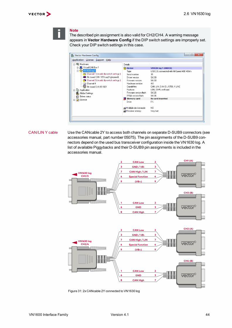
NoteThe described pin assignment is also valid for CH2/CH4. A warningmessageappears inVector Hardware Config if the DIP switch settings are improperly set.Check your DIP switch settings in this case.
CAN/LIN Y cable Use the CANcable 2Y to access both channels on separate D-SUB9 connectors (seeaccessories manual, part number 05075). The pin assignments of the D-SUB9 con-nectors depend on the used bus transceiver configuration inside the VN1630 log. Alist of available Piggybacks and their D-SUB9 pin assignments is included in theaccessories manual.
CAN4Low2 2
GND4/4VB-3 3
CAN4High4/4LIN7 7
Special4function4 4
CAN4Low41 2
GND46 3
CAN4High48 7
0VB+)9 9
VN16304logCH1/3
CAN4Low2 2
GND4/4VB-3 3
CAN4High4/4LIN7 7
Special4function4 4
CAN4Low41 2
GND46 3
CAN4High48 7
0VB+)9 9
VN16304logCH2/4
CH140A)
CH340B)
CH240A)
CH440B)
Figure 31: 2xCANcable 2Y connected to VN1630 log

2.6 VN1630 log
VN1600 Interface Family Version 4.1 45
2.6.7 Pin Assignment CH5Digital/analog IO The pin assignment for CH5 is
as follows:Pin Assignment1 Analog input2 Not connected3 Not connected4 Digital input 05 Digital input 16 Analog GND7 Not connected8 Digital output9 Digital GND
1
Analog GND1
2
3
4
59
8
7
66
Digital In 0
5
Digital Out
Digital GND
Analog In
4
Digital In 1
8
9
Internalinterconnection ofdigital input 0/1
To Processor
Digital GND
Vcc
Digital GND Digital GND
Digital Input 0/1
Isolation
20k
Vref
200k
OUT
IN-
IN+
33 V370 pF
Figure 32: Digital input 0/1
Internalinterconnection ofdigital output
From Processor
Digital Output
Digital GND
Isolation
33 V 370 pF
Figure 33: Digital output
Internalinterconnection ofanalog input
To Processor
Analog GND
Vcc
Analog Input
100k
1M
33 V370 pF
Analog GND
22 pFADC
15k
10k
Analog GND
OUT
IN+
IN-
Isolation
INOUT
Figure 34: Analog input

2.6 VN1630 log
VN1600 Interface Family Version 4.1 46
Extendedmeasuringrange of the analoginput
In normal operation, voltages up to 18 V can be applied andmeasured at the analoginput. The cutoff frequency fc (-3 dB) for AC voltages is approx. 7.2 kHz.
For measurements above 18 V (max. 50 V), an external series resistor has to beapplied to the analog input. The series resistor Rext depends on the input voltageUinput and can be calculated as follows:
The cutoff frequency for AC voltages is also affected by the external series resistor:
Examples 24 V 32 V 36 V 48 VRext 367 kΩ 856 kΩ 1100 kΩ 1833 kΩRext (E96) 374 kΩ
(24.12 V)866 kΩ(32.17 V)
1100 kΩ(36.00 V)
1870 kΩ(48.60 V)
fc (-3 dB) 1148 Hz 496 Hz 390 Hz 230 Hz

2.6 VN1630 log
VN1600 Interface Family Version 4.1 47
2.6.8 Replacing Piggybacks
Caution!When performing this operation be sure not to touch the top or bottom of the boards(VN1630 logmain board or Piggybacks) to avoid damages due to electrical dis-charges.
Step by Step Procedure1. First, loosen the VN1630 log housing screws on the side with the two D-SUB9
connectors. This requires removing the two black decorative caps. Then care-fully pull the PC-board out of the housing.
Figure 35: Opening the housing
2. You will find the plug-in location 1 (CH1) at the sync connector side and plug-inlocation 2 (CH2) at the edge of the PC-board.
Piggy 1(CH1)
Piggy 2(CH2)
Figure 36: Piggybackplug-in locationsCH1 and CH2

2.6 VN1630 log
VN1600 Interface Family Version 4.1 48
3. Each Piggyback is fastened by a screw and retainer. Please loosen the appro-priate screw including the retainer and carefully remove the Piggyback from theplug-in location.
CH2
CH1
Figure 37: Unmount/mount Piggybacks
4. Set the DIP switches as described in section Pin Assignment CH1/3 andCH2/4 on page 42.
5. Insert the replacement Piggyback. When doing this pleasemake sure that thesingle and dual-row connectors are not laterally offset.
6. Secure the new Piggyback with the appropriate screw and retainer.

2.6 VN1630 log
VN1600 Interface Family Version 4.1 49
7. Place the VN1630 logmain board back in the housing. This operation involvesplacing the housing on a table with its back side (side with the bar code) facingupward. Then themain board with the Piggybacks facing upward is insertedinto the first guide rails.
Figure 38: First guide rails
8. It should be possible to slide themain board in the housing up to a few mil-limeters from the end without forcing it in. Close the housing by applying lightpressure and then secure it with the appropriate screw fasteners. The screwsshould be secure but not excessively tight.
9. Please also attach the two black decorative caps.
10. Connect the VN1630 log and the PC via the USB cable and check the bus con-figuration inVector Hardware Config.
Figure 39: Check inserted Piggybacks

2.6 VN1630 log
VN1600 Interface Family Version 4.1 50
2.6.9 SD/SDHC Memory CardsSD/SDHC cards The logger supports industrial grade SD/SDHC memory cards up to 32GB. For the
proper use only industrial grade cards released by Vector are recommended:
SD card
> Xmore industrial 2 GB (SD-2G0-XIE82)
SDHC cards
> Xmore industrial 8 GB (SD-8G0-XIE82)
> Xmore industrial 16 GB (SD-16G-XIE82)
> SanDisk Industrial XT 32GB (SDSDAF-032G-XI)
NoteThememory cards have to be FAT32 formatted. For optimum speed, we recom-mend FAT32 formatting with themaximum available cluster size.
2.6.10 Ring Buffer in RAMMemory The VN1630 log has an allocated ring buffer in its RAM (32MB) which is used to buf-
fer received data. During recording, the data is continually written to the SD card.When using a triggered recording, the data is only stored into the ring buffer until thetrigger event occurs. The data is then copied from the ring buffer to the SD cardaccording to the set pre-trigger time.
2.6.11 Real Time ClockDescription The VN1630 log has a real time clock for date/time information while logging. The real
time clock can be set up in theVector Logger Configurator. It is recommended toset the real time clock before first logging.
2.6.12 BatteryLifetime The VN1630 log is equipped with a lithium battery that powers the integrated real time
clock. The battery has a typical durability of approx. 5 years.
2.6.13 BeepBeep VN1630 log has an acoustic signal generator which acoustically alerts the user e. g. in
case of a trigger. Triggers with beeps can be defined in theVector Logger Con-figurator.

2.6 VN1630 log
VN1600 Interface Family Version 4.1 51
2.6.14 Technical Data
CAN channels Max. 42x CAN high-speed 1051cap2x configurable via PiggybacksCAN: up to 2Mbit/sCAN FD: up to 8Mbit/s
LIN channels Max. 2configurable via Piggybacksup to 330 kbit/s
K-Line channels Max. 2with LINpiggy 7269mag at CH1/CH2
J1708 channels Max. 2configurable via Piggybacks
Analog input 10 bitInput 0 V...18 VVoltage tolerance up to 50 V(with series resistor)Sampling rate up to 1 kHz
Digital input Range 0 V...32 VSchmitt trigger high 2.7 V, low 2.2 VHysteresis 0.5 VInput frequencies up to 1 kHz
Digital output OpenDrainExternal supply up to 32 VCurrent max. 500mAShort circuit / over voltage protected
Operation mode Interface and loggingMemory function Logging on SD/SDHC cardExtras Real time clockStartup time (Logging Mode) 3 seconds after power-upBattery Lithium primary cell type BR2330APower supply InterfaceMode: via USB
Logging Mode: 6 V...50 VPower consumption Approx. 2.5WTemperature range Operating: -40 °C...+65 °C
Shipping and storage: -40 °C...+85 °CRelative humidity of ambient air 15%...95%, non-condensingDimensions (LxWxH) Approx.150mm x 110mm x 35mmWeight 400 g (without accessories)Operating system requirements Windows 7 SP1 (32 bit / 64 bit)
Windows 8.1 (32 bit / 64 bit)Windows 10 (64 bit)

2.7 VN1640A
VN1600 Interface Family Version 4.1 52
2.7 VN1640A
2.7.1 Main FeaturesVN1640A features Themain features of the VN1640A interface are:
> 4x plug-in location for CAN-/LINpiggies
> Fifth channel for dedicated digital-analog input/output tasks
> 5x D-SUB9 connector
> Five LEDs indicating bus activities and status
> Software sync
> Hardware sync (via SYNCcableXL)
Figure 40: VN1640ACAN/LIN Interface
2.7.2 Connectors Bus SideDevice connectors
Figure 41: VN1640Awith syncand D-SUB9 connectors
> Binder connector (Sync)This connector (Binder type 711) can be used for time synchronization of differentVector devices (see section Time Synchronization on page 77). The sync con-nector is not intended to connect a power supply.

2.7 VN1640A
VN1600 Interface Family Version 4.1 53
Pin Assignment1 Not connected2 Synchronization line3 Ground
312
> D-SUB9 (CH1...4)The VN1640A has four D-SUB9 connectors, each assigned to a dedicated Piggy-back plug-in location. Further information on the pin assignment can be found insection Pin Assignment CH1...CH4 on page 56.
2.7.3 Connectors USB SideDevice connectors
Figure 42: VN1640Awith USBand D-SUB9 connector
> USBConnect your PC and the VN1640A via USB to install and to use the device withmeasurement applications (e. g. CANoe, CANalyzer). Use the USB2.0 compliantcable found in the delivery (USB extension cables may generate faults betweenthe PC and the device). Connect the device directly to USB at your PC or use aUSB hub with its own power supply (self-powered). Depending on the used Piggy-back, the VN1640A requires the entire USB current (500mA) which cannot beprovided by a bus-powered USB hub.
> D-SUB9 (CH5)The VN1640A has a D-SUB9 connector (CH5) for dedicated digital-analoginput/output tasks. The pin assignment can be found in section Pin AssignmentCH5 on page 57.

2.7 VN1640A
VN1600 Interface Family Version 4.1 54
2.7.4 LEDsDescription The VN1640A has five LEDs indicating bus activities and status:
Figure 43: LEDsof the VN1640A
> CH1 … CH4 (with CAN-/LINpiggies)Multicolored channel LEDs, each indicating the bus activity for CAN, LIN or K-Line.Color DescriptionGreen Data frames have been sent or received correctly.Orange CAN: Error frames have been sent or received.
LIN/K-Line: Protocol errors as well as valid messages on the bus.Red CAN: Bus off.
LIN/K-Line: Protocol errors on the bus.CAN: The flashing frequencydependson the bus load.
> StatusMulticolored LED that indicates the status of the device.Color DescriptionGreen Device is ready for operation/runningmeasurement.Orange Initializing driver. Please wait.Red Error. Device not working.
2.7 VN1640A
VN1600 Interface Family Version 4.1 55
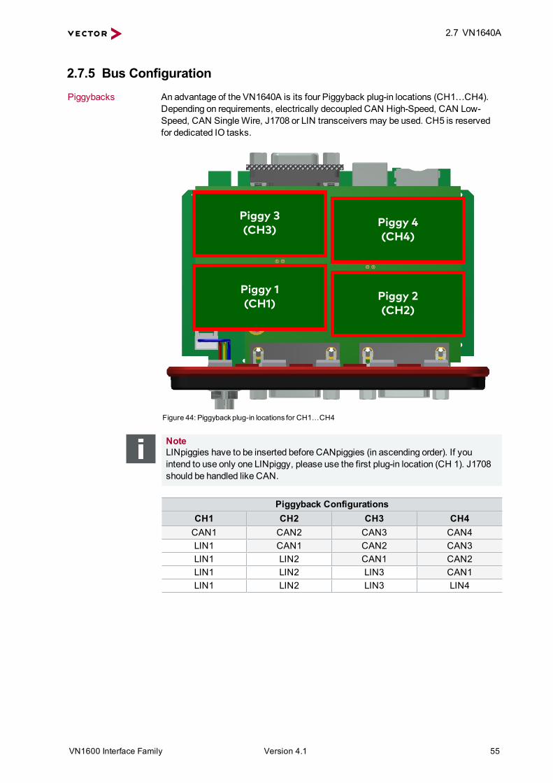
2.7.5 Bus ConfigurationPiggybacks An advantage of the VN1640A is its four Piggyback plug-in locations (CH1…CH4).
Depending on requirements, electrically decoupled CAN High-Speed, CAN Low-Speed, CAN SingleWire, J1708 or LIN transceivers may be used. CH5 is reservedfor dedicated IO tasks.
Piggy 3(CH3)
Piggy 1(CH1)
Piggy 4(CH4)
Piggy 2(CH2)
Figure 44: Piggybackplug-in locations for CH1…CH4
NoteLINpiggies have to be inserted before CANpiggies (in ascending order). If youintend to use only one LINpiggy, please use the first plug-in location (CH 1). J1708should be handled like CAN.
Piggyback ConfigurationsCH1 CH2 CH3 CH4CAN1 CAN2 CAN3 CAN4LIN1 CAN1 CAN2 CAN3LIN1 LIN2 CAN1 CAN2LIN1 LIN2 LIN3 CAN1LIN1 LIN2 LIN3 LIN4

2.7 VN1640A
VN1600 Interface Family Version 4.1 56
Examples The following tables show examples of possible configurations:
1x CAN CH1 CH2 CH3 CH4CANpiggy 1 - - -
1x LIN CH1 CH2 CH3 CH4LINpiggy 1 - - -
1x LIN1x CAN CH1 CH2 CH3 CH4
LINpiggy 1 CANpiggy 1 - -
1x LIN1x CAN CH1 CH2 CH3 CH4
- LINpiggy 1 - CANpiggy 1
2x LIN1x CAN CH1 CH2 CH3 CH4
LINpiggy 1 LINpiggy 2 CANpiggy 1 -
2.7.6 Pin Assignment CH1...CH4Assignment of theD-SUB9 connectors
The pin assignments depend on the inserted Piggybacks. A list of available Piggy-backs and their D-SUB9 pin assignments can be found in the separate accessoriesmanual on the Vector Driver Disk in \Documentation\Accessories.
ExampleCANpiggy 1041magThe following example shows the pin assignment of CH1 if a CANpiggy 1041mag isinserted in the plug-in location at channel 1:
5
4
3
2
16
7
8
9Shield
1041magwVB+1041magwSplit
1041magwVB-
1041magwCANwLow1041magwCANwHigh
CH1
NC
NC
NC
2.7 VN1640A
VN1600 Interface Family Version 4.1 57
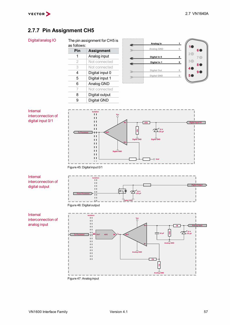
2.7.7 Pin Assignment CH5Digital/analog IO The pin assignment for CH5 is
as follows:Pin Assignment1 Analog input2 Not connected3 Not connected4 Digital input 05 Digital input 16 Analog GND7 Not connected8 Digital output9 Digital GND
1
Analog GND1
2
3
4
59
8
7
66
Digital In 0
5
Digital Out
Digital GND
Analog In
4
Digital In 1
8
9
Internalinterconnection ofdigital input 0/1
To Processor
Digital GND
Vcc
Digital GND Digital GND
Digital Input 0/1
Isolation
20k
Vref
200k
OUT
IN-
IN+
33 V370 pF
Figure 45: Digital input 0/1
Internalinterconnection ofdigital output
From Processor
Digital Output
Digital GND
Isolation
33 V 370 pF
Figure 46: Digital output
Internalinterconnection ofanalog input
To Processor
Analog GND
Vcc
Analog Input
100k
1M
33 V370 pF
Analog GND
22 pFADC
15k
10k
Analog GND
OUT
IN+
IN-
Isolation
INOUT
Figure 47: Analog input
2.7 VN1640A
VN1600 Interface Family Version 4.1 58
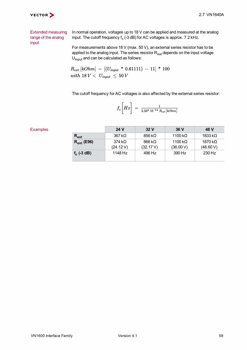
Extendedmeasuringrange of the analoginput
In normal operation, voltages up to 18 V can be applied andmeasured at the analoginput. The cutoff frequency fc (-3 dB) for AC voltages is approx. 7.2 kHz.
For measurements above 18 V (max. 50 V), an external series resistor has to beapplied to the analog input. The series resistor Rext depends on the input voltageUinput and can be calculated as follows:
The cutoff frequency for AC voltages is also affected by the external series resistor:
Examples 24 V 32 V 36 V 48 VRext 367 kΩ 856 kΩ 1100 kΩ 1833 kΩRext (E96) 374 kΩ
(24.12 V)866 kΩ(32.17 V)
1100 kΩ(36.00 V)
1870 kΩ(48.60 V)
fc (-3 dB) 1148 Hz 496 Hz 390 Hz 230 Hz

2.7 VN1640A
VN1600 Interface Family Version 4.1 59
2.7.8 Replacing Piggybacks
Caution!When performing this operation be sure not to touch the top or bottom of the boards(VN1640A main board or Piggybacks) to avoid damages due to electrical dis-charges.
Step by Step Procedure1. First, loosen the VN1640A housing screws on the side with the four D-SUB9
connectors. This requires removing the two black decorative caps. Then care-fully pull the PC-board out of the housing.
Figure 48: Opening the housing
2. The plug-in locations are defined as follows:
Piggy 3(CH3)
Piggy 1(CH1)
Piggy 4(CH4)
Piggy 2(CH2)
Figure 49: Piggybackplug-in locationsCH1…CH4

2.7 VN1640A
VN1600 Interface Family Version 4.1 60
3. Each Piggyback is fastened by a screw and retainer. Please loosen the appro-priate screw including the retainer and carefully remove the Piggyback from theplug-in location.
CH2
CH4
CH1
CH3
Figure 50: Unmount/mount Piggybacks
4. Insert the replacement Piggyback. When doing this pleasemake sure that thesingle and dual-row connectors are not laterally offset.
5. Secure the new Piggyback with the appropriate screw and retainer.

2.7 VN1640A
VN1600 Interface Family Version 4.1 61
6. Place the VN1640A main board back in the housing. This operation involves pla-cing the housing on a table with its back side (side with the bar code) facingupward. Then themain board with the Piggybacks facing upward is insertedinto the first guide rails.
Figure 51: First guide rails
7. It should be possible to slide themain board in the housing up to a few mil-limeters from the end without forcing it in. Close the housing by applying lightpressure and then secure it with the appropriate screw fasteners. The screwsshould be secure but not excessively tight.
8. Please also attach the two black decorative caps.
9. Connect the VN1640A and the PC via the USB cable and check the bus con-figuration inVector Hardware Config.
Figure 52: Check inserted Piggybacks

2.7 VN1640A
VN1600 Interface Family Version 4.1 62
2.7.9 Technical Data
CAN channels Max. 4configurable via PiggybacksCAN: up to 2Mbit/sCAN FD: up to 8Mbit/s
LIN channels Max. 4configurable via Piggybacksup to 330 kbit/s
K-Line channels Max. 2with LINpiggy 7269mag at CH1/CH2
J1708 channels Max. 4configurable via Piggybacks
Analog input 10 bitInput 0 V...18 VVoltage tolerance up to 50 V(with series resistor)Sampling rate up to 1 kHz
Digital input Range 0 V...32 VSchmitt trigger high 2.7 V, low 2.2 VHysteresis 0.5 VInput frequencies up to 1 kHz
Digital output OpenDrainExternal supply up to 32 VCurrent max. 500mAShort circuit / over voltage protected
Power consumption Approx. 2.5WTemperature range Operating: -40 °C...+70 °C
Shipping and storage: -40 °C...+85 °CRelative humidity of ambient air 15%...95%, non-condensingDimensions (LxWxH) Approx. 88mm x 111mm x 45mmWeight 330 g (without accessories)Operating system requirements Windows 7 SP1 (32 bit / 64 bit)
Windows 8.1 (32 bit / 64 bit)Windows 10 (64 bit)

2.7 VN1640A
VN1600 Interface Family Version 4.1 63
3 Getting StartedIn this chapter you find the following information:
3.1 Driver Installation 64
3.2 Device Configuration 67
3.3 Quick Test 68
3.4 Loop Tests 693.4.1 CAN 69

3.1 Driver Installation
VN1600 Interface Family Version 4.1 64
3.1 Driver InstallationGeneralinformation
The Vector Driver Disk offers a driver setup which allows the installation or theremoval of Vector devices.
NotePlease note that you will needAdministrator Rights for the following steps.
Step by Step Procedure
1. Execute the driver setup from the autostart menu or directly from\Drivers\Setup.exe before the device is connected to the PC with theincluded USB cable.
If you have already connected the device to the PC, theWindows found newHardwarewizard appears. Close this wizard and then execute the driver setup.
2. Click [Next] in the driver setup dialog. The initialization process starts.

3.1 Driver Installation
VN1600 Interface Family Version 4.1 65
3. In the driver selection dialog, select your devices to be installed (or to be unin-stalled).
4. Click [Install] to execute the driver installation, or [Uninstall] to remove exist-ing drivers.
5. A confirmation dialog appears. Click [Close] to exit. After successful instal-lation, the device is ready for operation and can be connected to the PC withthe included USB cable.

3.1 Driver Installation
VN1600 Interface Family Version 4.1 66
Step by Step ProcedureFor VN1630 log users only:Please also install theVector Logger Configurator as follows:
1. Execute \Tools\VN1630_log\Setup.exe.
2. Finish the installation with the setup.
ReferenceInformation on the configuration of the LoggingMode and export of recorded datacan be found in the separatemanual provided with theVector Logger Con-figurator.

3.2 Device Configuration
VN1600 Interface Family Version 4.1 67
3.2 Device ConfigurationConfiguration Before the installed device can be used in an application, it must be properly con-
figured for the needed use case. This configuration is done with theVector HardwareConfig tool which comes with the driver installation. The tool can be found inWin-dows | Start | Settings | Control Panel | Vector Hardware andmanages allinstalled Vector devices.
ReferenceFurther details onVector Hardware Config can be found in the installation instruc-tions (see section Vector Hardware Configuration on page 71).

3.3 Quick Test
VN1600 Interface Family Version 4.1 68
3.3 Quick TestReferencePlease execute the test as descibed in section Loop Tests on page 69.

3.4 Loop Tests
VN1600 Interface Family Version 4.1 69
3.4 Loop TestsOperation test The test described here can be performed to check the functional integrity of the driver
and the device. This test is identical forWindows 7 / Windows 8.1 / Windows 10 andindependent of the used application.
3.4.1 CANDevice test The operating test for CAN can be executed with the following devices:
> CANcardXL/XLe> CANcaseXL/XL log> CANboardXL Family> VN1610 / VN1630A / VN1630 log / VN1640A> VN5610A> VN7570 / VN7572 / VN7600 / VN7640> VN8911 with VN8970> VN8912A / VN8914 with VN8970 / VN8972
Loop3.exe Either two high-speed or two low-speed transceivers are necessary for this functionaltest:
Step by Step Procedure
1. Connect two CAN channels with a suitable cable.If two high-speed transceivers are being used, we recommend ourCANcable1 (CANcable0 for low-speed transceivers).
2. Start \Drivers\Common\Loop3.exe from the Vector Driver Disk.This program accesses the Vector devices and transmits CAN messages.
3. Select the connected CAN channels of the device(s) to be tested.

3.4 Loop Tests
VN1600 Interface Family Version 4.1 70
4. Set the appropriate baudrate depending on the transceiver being used (high-speedmax. 1,000,000 Bd, low-speedmax. 125,000 Bd).
5. Click [Start].
6. You will see statistical data in the lower part of the window if the system hasbeen configured properly.
7. The test procedure can be terminated with the [Stop] button.AnOK should appear in the upper part of the window.

VN1600 Interface Family Version 4.1 71
4 Vector Hardware ConfigurationIn this chapter you find the following information:
4.1 General Information 72
4.2 Tool Description 734.2.1 Introduction 734.2.2 Tree View 74

4.1 General Information
VN1600 Interface Family Version 4.1 72
4.1 General InformationExecuting VectorHardware Config
After the successful driver installation you will find the configuration applicationVector Hardware in the Control Panel (see below). The tool gives you informationabout the connected and installed Vector devices. There are also several settings thatcan be changed.
Figure 53: Icon in Control Panel
Control PanelWindows 7
> Category viewWindows Start | Control Panel | Hardware and Sound,click Vector Hardware in the list.
> Symbols viewWindows Start | Control Panel,click Vector Hardware in the list.
Control PanelWindows 8.1
> Category view<Windows key>+<X> | Control Panel | Hardware and Sound,click Vector Hardware in the list.
> Symbols view<Windows key>+<X> | Control Panel,click Vector Hardware in the list.
Control PanelWindows 10
> Category view<Windows key>+<X> | Control Panel | Hardware and Sound,click Vector Hardware in the list.
> Symbols view<Windows key>+<X> | Control Panel,click Vector Hardware in the list.

4.2 Tool Description
VN1600 Interface Family Version 4.1 73
4.2 Tool Description
4.2.1 IntroductionVectorHardware Config
Figure 54: General view of Vector Hardware Config
Logical and physicalchannels
Vector Hardware Config enables the channel configuration between installed Vectordevices and applications. Applications use so-called logical channels which are hard-ware independent and have to be assigned to real hardware channels.
physical CH1CAN
physical CH2LIN
Vector Device 1 Vector Device 2
physical CH1FlexRay
physical CH2CAN
not assigned
logical channelCAN 1
Applicationlogical channel
LIN 1logical channel
CAN 1
logical channelFlexRay 1
logical channelCAN 2
Figure 55: Concept of channel assignments
Figure 56: Channel assignment in Vector Hardware Config

4.2 Tool Description
VN1600 Interface Family Version 4.1 74
4.2.2 Tree ViewAccessingVector devices
The tool is split into two windows. The left window has a tree view and lets youaccess the installed Vector devices, the right window displays the details of the selec-tion. The following nodes are available in the tree view:
Hardware TheHardware section lists the installed Vector devices. Each device item has phys-ical channels which can be assigned to any number of logical channels (e. g.CANalyzer CAN 1). A logical channel can be assigned to only one physical channel.
Figure 57: Hardware
Application InApplication, all available applications are displayed in a tree view. According toeach application, the assignments of logical and physical channels are displayed inthe right part of the window. If no assignment exists, the informationNot assignedappears. The assignment can be edited via a right-click.
Figure 58: Application

4.2 Tool Description
VN1600 Interface Family Version 4.1 75
Global settings Global settings contains global device configuration possibilities, e. g. software timesynchronization, transmit queue size, configuration flags or the number of virtual CANdevices.
Figure 59: Global settings
Driver status Driver status offers an overall status information of devices and applications cur-rently in use. You can see whether the channels are connected to the bus (online/off-line) and whether the time synchronization is activated or not (Time-Sync-On/Time-Sync-Off).
Figure 60: Driver status

4.2 Tool Description
VN1600 Interface Family Version 4.1 76
License The License section contains information on all current available licenses (Vector busdevices, Vector License USB dongle devices).
Figure 61: License
ReferenceYouwill find a detailed description of Vector Hardware Config in the online help(Help | Contents).

VN1600 Interface Family Version 4.1 77
5 Time SynchronizationIn this chapter you find the following information:
5.1 General Information 78
5.2 Software Sync 80
5.3 Hardware Sync 81
5.1 General Information
VN1600 Interface Family Version 4.1 78
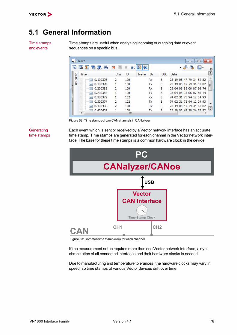
5.1 General InformationTime stampsand events
Time stamps are useful when analyzing incoming or outgoing data or eventsequences on a specific bus.
Figure 62: Time stampsof two CAN channels in CANalyzer
Generatingtime stamps
Each event which is sent or received by a Vector network interface has an accuratetime stamp. Time stamps are generated for each channel in the Vector network inter-face. The base for these time stamps is a common hardware clock in the device.
CAN
VectorCAN Interface
CH1 CH2
Time Stamp Clock
PCCANalyzer/CANoe
USB
Figure 63: Common time stamp clock for each channel
If themeasurement setup requires more than one Vector network interface, a syn-chronization of all connected interfaces and their hardware clocks is needed.
Due tomanufacturing and temperature tolerances, the hardware clocks may vary inspeed, so time stamps of various Vector devices drift over time.

5.1 General Information
VN1600 Interface Family Version 4.1 79
CAN
FlexRay
VectorCAN Interface
CH1 CH2Time Stamp Clock
PC
VectorFR Interface
CHA CHBTime Stamp Clock
sec0.0000000.1003760.2003820.3003720.4004060.5005930.600242
sec0.0000000.1003830.2009820.3014560.4026120.5038850.604092
CANalyzer/CANoeUSB USB
Figure 64: Example of unsynchronized network interfaces. Independent time stampsdrift apart
To compensate for these time stamp deviations between the Vector network inter-faces, the time stamps can be either synchronized by software or by hardware (seenext section).
NoteThe accuracy of the software and hardware sync depends on the interface. Furtherinformation on specific values can be found in the technical data of the respectivedevices.

5.2 Software Sync
VN1600 Interface Family Version 4.1 80
5.2 Software SyncSynchronizationby software
The software time synchronization is driver-based and available for all applicationswithout any restrictions. The time stamp deviations from different Vector network inter-faces are calculated and synchronized to the common PC clock. For this purpose nofurther hardware setup is required.
CAN
FlexRay
VectorCAN Interface
CH1 CH2Time Stamp Clock
VectorFR Interface
CHA CHBTime Stamp Clock
synchronizationby software (PC clock)
sec0.0000001.1003561.2003622.3003622.4003563.5003533.600362
PC
sec0.0000001.1004131.2004212.3004292.4004193.5004153.600420
PC clockCANalyzer/CANoeUSB USB
Figure 65: Time stampsof devicesare synchronized to the PC clock
The setting of the software time synchronization can be changed in theVector Hard-ware Config tool inGeneral information | Settings | Software time syn-chronization.
Figure 66: Switching on the software synchronization
> YESThe software time synchronization is active.
> NOThe software time synchronization is not active. Use this setting only if the Vectornetwork interfaces are being synchronized over the sync line or if only a singledevice is used.

5.3 Hardware Sync
VN1600 Interface Family Version 4.1 81
5.3 Hardware SyncSynchronizationby hardware
A more accurate time synchronization of multiple devices is provided by the hardwaresynchronization which has to be supported by the application (e. g. CANalyzer,CANoe). Two Vector network interfaces can therefore be connected with theSYNCcableXL (see accessories manual, part number 05018).
In order to synchronize up to five devices at the same time, a distribution box is avail-able (see accessories manual, part number 05085).
VN1630A
VN5610A
VN1640A
Multi SYNCbox external
VN1640A
USB PC
PC
VN7570
SYNCcable XL
SYNCcable XL
SYNCcable XL
SYNCcable XL
USB PC
Vector Devices
USB PC
USB PC
USB PC
Power
Figure 67: Example of a time synchronization with multiple devices
VN5610A
VN8912A
Power
VN5610A
VN1640A
Multi SYNCbox external
VN1640A
USB
VN
8912
A
USB PC
SYNCcable XLSYNCcable XL
SYNCcable XL
SYNCcable XL
Power
Power
Figure 68: Example of a time synchronization with VN8912A and additional devices
At each falling edge on the sync line which is initiated by the application, the Vectornetwork interface generates a time stamp that is provided to the application. This

5.3 Hardware Sync
VN1600 Interface Family Version 4.1 82
allows the application to calculate the deviations between the network interfaces andto synchronize the time stamps to a common time base (master clock) which isdefined by the application.
CANalyzer/CANoe
CAN
FlexRay
VectorCAN Interface
CH2Time Stamp Clock
USB
VectorFR Interface
CHBMaster Time Stamp Clock
synchronizationby hardware (SYNCcable)
sec0.0000001.1003751.2003812.3003712.4004053.5005923.600241
CH1 CHA
sec0.0000001.1003761.2003822.3003722.4004063.5005933.600242
PC
USB
Figure 69: Time stampsare synchronized to themaster clock
NoteThe hardware synchronizationmust be supported by the application. For furtherinformation please refer to the relevant applicationmanual. Please note that the soft-ware synchronizationmust be disabled (seeVector Hardware Config | Generalinformation | Settings | Software time synchronization) if the hardware syn-chronization is used.

Get More Information
Visit our website for:> News> Products> Demo software> Support> Training classes> Addresses
www.vector.com


