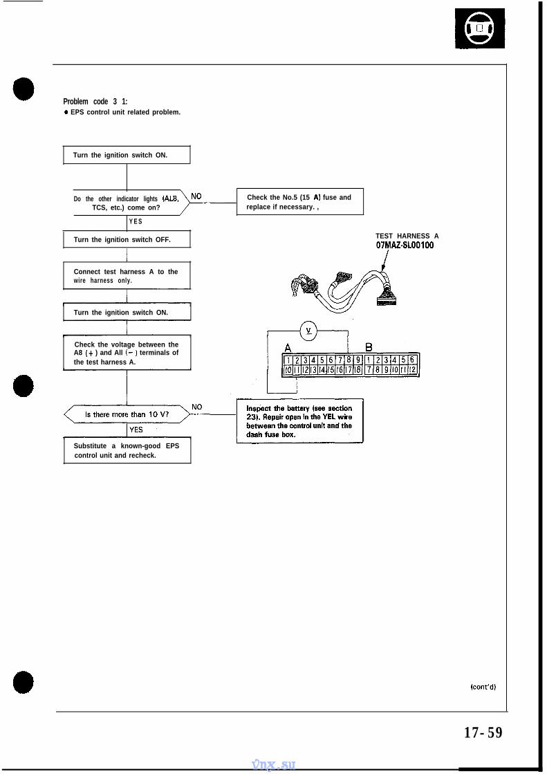
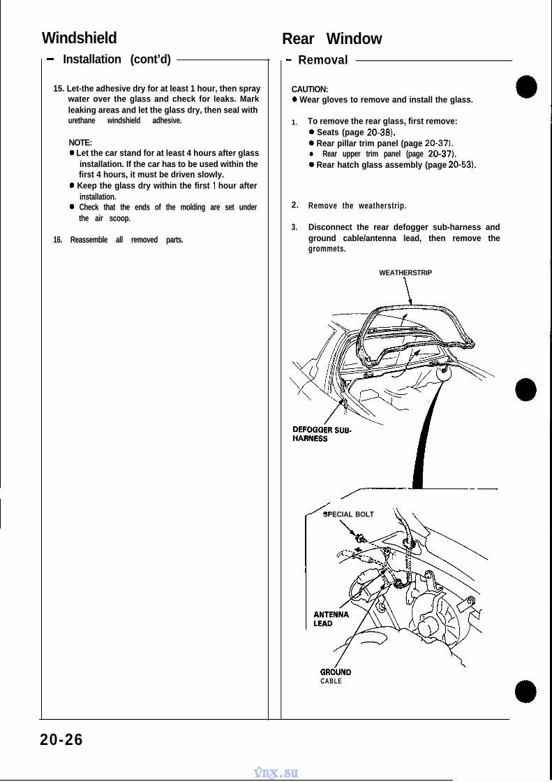
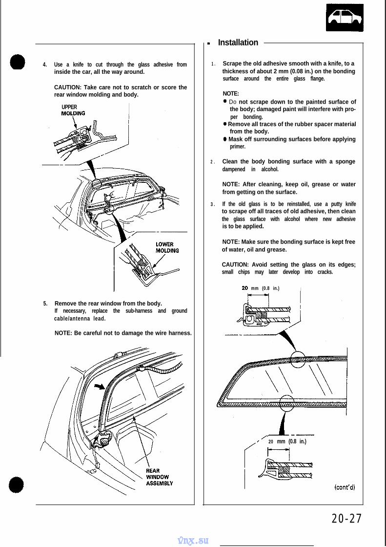
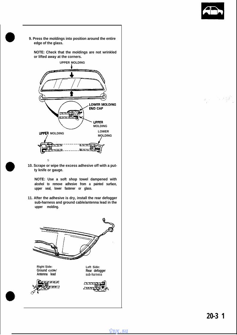
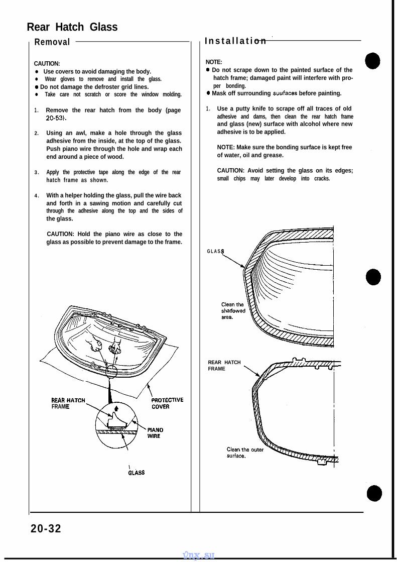
l!!!!!a O0 c From page 14-74 ,&, Reconnect the 26P and 22P conectors to the control unit. I Turn the ignition switch ON. Be sure that the voltage is available for 2 seconds between the A8 (YELIBLK) terminal and A25 (BRN/WHT) terminal. Is there voltage? NO Turn the ignition switch OFF. Disconnect the 26P and 22P con- nectors from the control unit. Check for continuity between the A8 (YELIBLK) terminal and the gauge assembly. Repair open or short BLKlYEL wire between the A23 andlor A24 terminals and dash fuse box. Check for open or short in YELlBLK wire be- tween the A8 terminal and the gauge assem- bly. If wire is OK, check the D indicator light and the shift position in- dicator. Check for loose control unit con- nectors. Check the shift position console switch. If necessary, sub- stitute a known-good control unit and recheck. NOTE: View from terminal side. kont’d) vnx.su
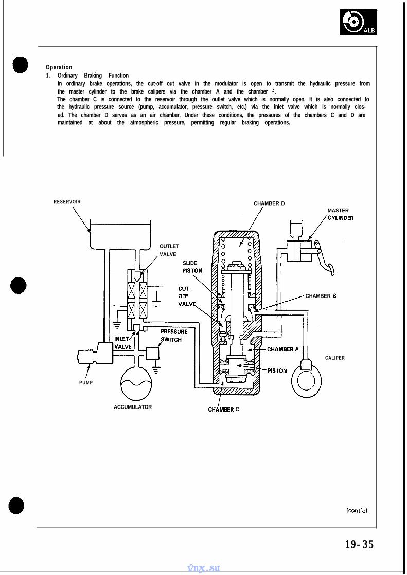
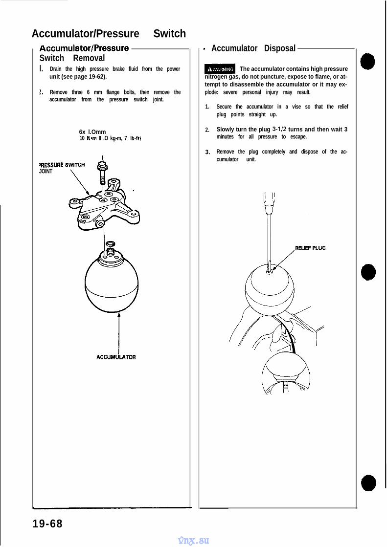
Transcript
l!!!!!aO0
c
From page 14-74
,&,Reconnect the 26P and 22Pconectors to the control unit.
ITurn the ignition switch ON. Besure that the vol tage is avai lablefor 2 seconds between the A8(YELIBLK) terminal and A25(BRN/WHT) terminal.
Is there voltage?
N O
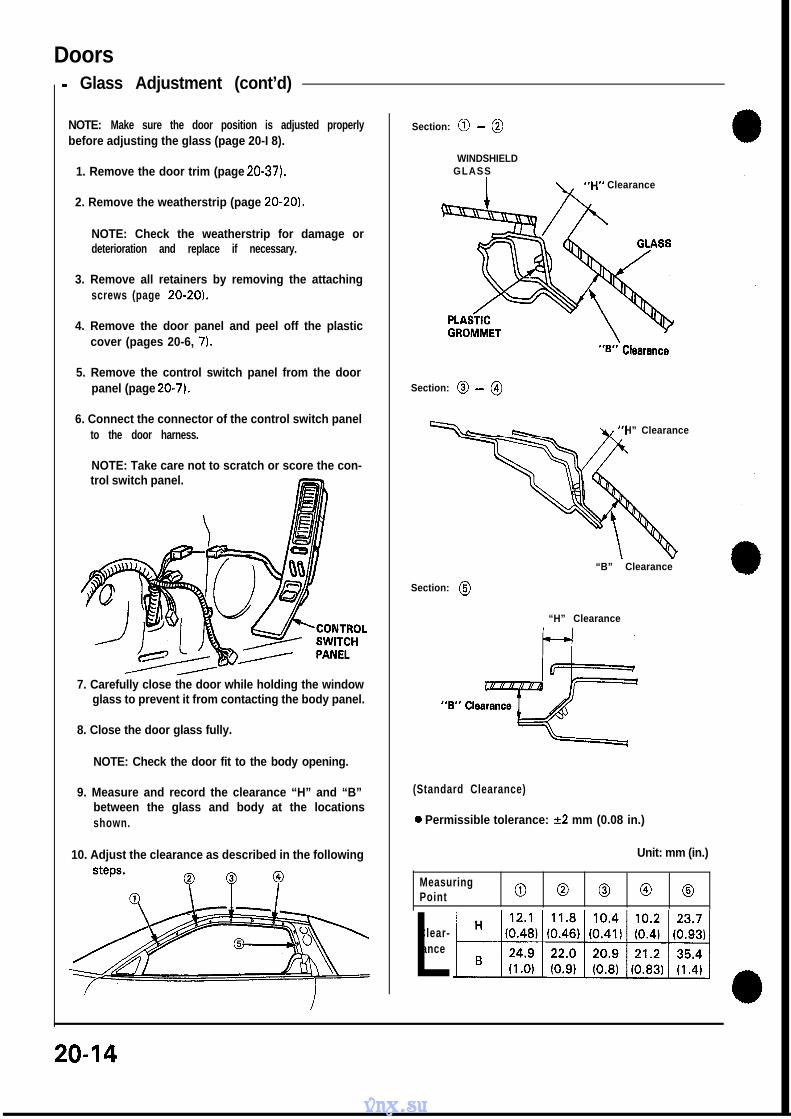
Turn the ignition switch OFF.
Disconnect the 26P and 22P con-nectors from the control unit.
Check for continuity between theA8 (YELIBLK) terminal and thegauge assembly.
Repair open or shortBLKlYEL wire betweenthe A23 andlor A24terminals and dash fusebox.
Check for open or shortin YELlBLK wire be-tween the A8 terminaland the gauge assem-bly. If wire is OK, checkthe D indicator light andthe shift position in-dicator .
Check for loose control unit con-nectors. Check the shift positionconsole switch. If necessary, sub-stitute a known-good control unitand recheck.
NOTE: View from terminal side.
kont’d)
vnx.su
-1rroubleshooting Flowchart (ckt’d)
rD indicator light is on steady, not,,...Ibknkmg whenever the lgnitton
NOTE: View from terminal side.
Measure voltage between the A8til/
YElJBLK
Is there voltage?Replace the A/l controlunit.
Y E SI I
Measure voltage between theYELIBLK wire at the gauge assem-bly and body ground.
Is there voltage?
Y E S
N O Replace faulty shift po-sition indicator.
14-76
vnx.su
4B
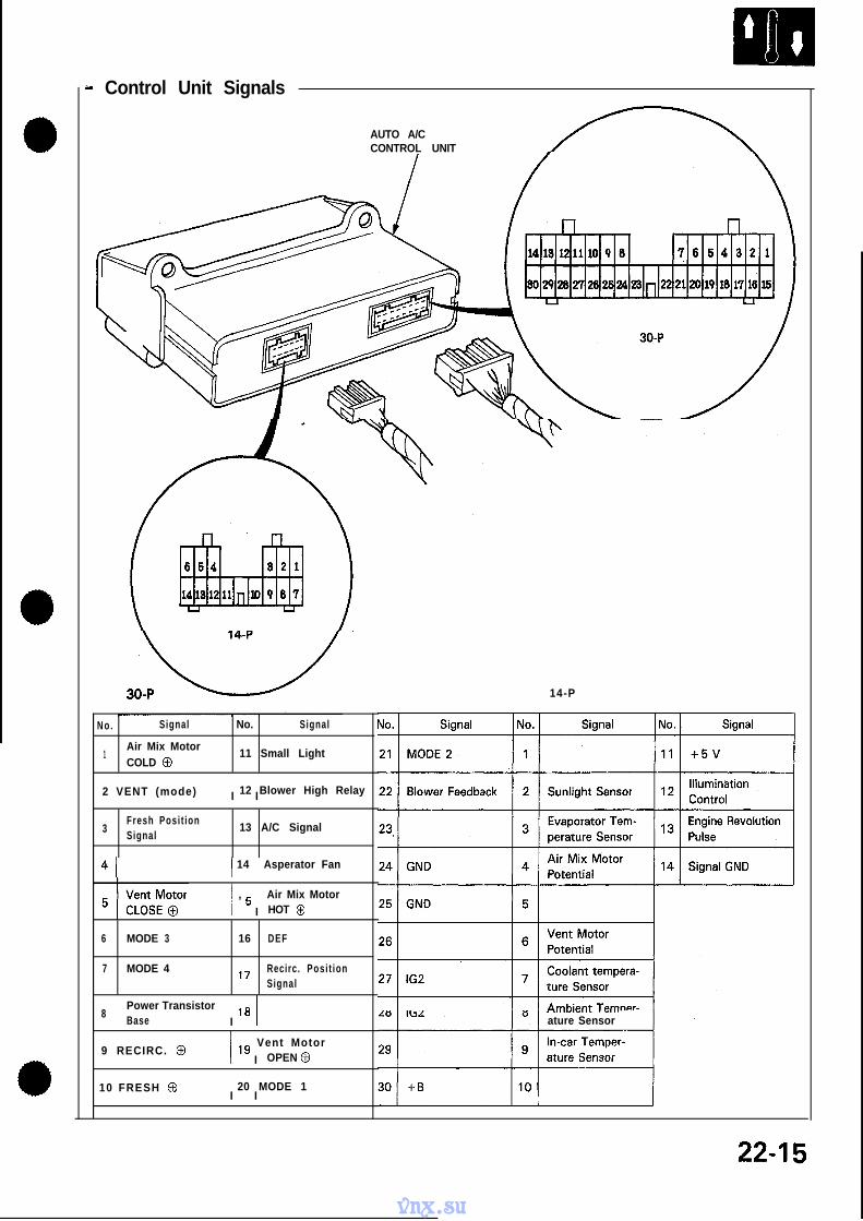
Inspection of the A/C signal.
I
(] Turn the blo;er switch ON.
Puch the A/C switch ON.
See Air Conditioner inspection.(Section 22.)
1 Y E S
Stop the engine.
II I
I Disconnect the 26P connectorfrom the control unit.
,I
I
I Start the engine.
Measure the voltage betweenA 2 2 (RED/BLU) a n d A 2 5(BRN/WHT) terminals. (A/C com-pressor OFF)
Is there battery voltage?NO Repair open in REDlBLU wire be-
tween A22 terminal and Auto AICcontrol unit.
II A/C signal is OK.
1
Lock-up Control Solenoid Valve A/B
i
Test
NOTE: Lock-up control solenoid valves A and B must be
removed/replaced as an assembly.
1 . Disconnect the connector from the lock-up control
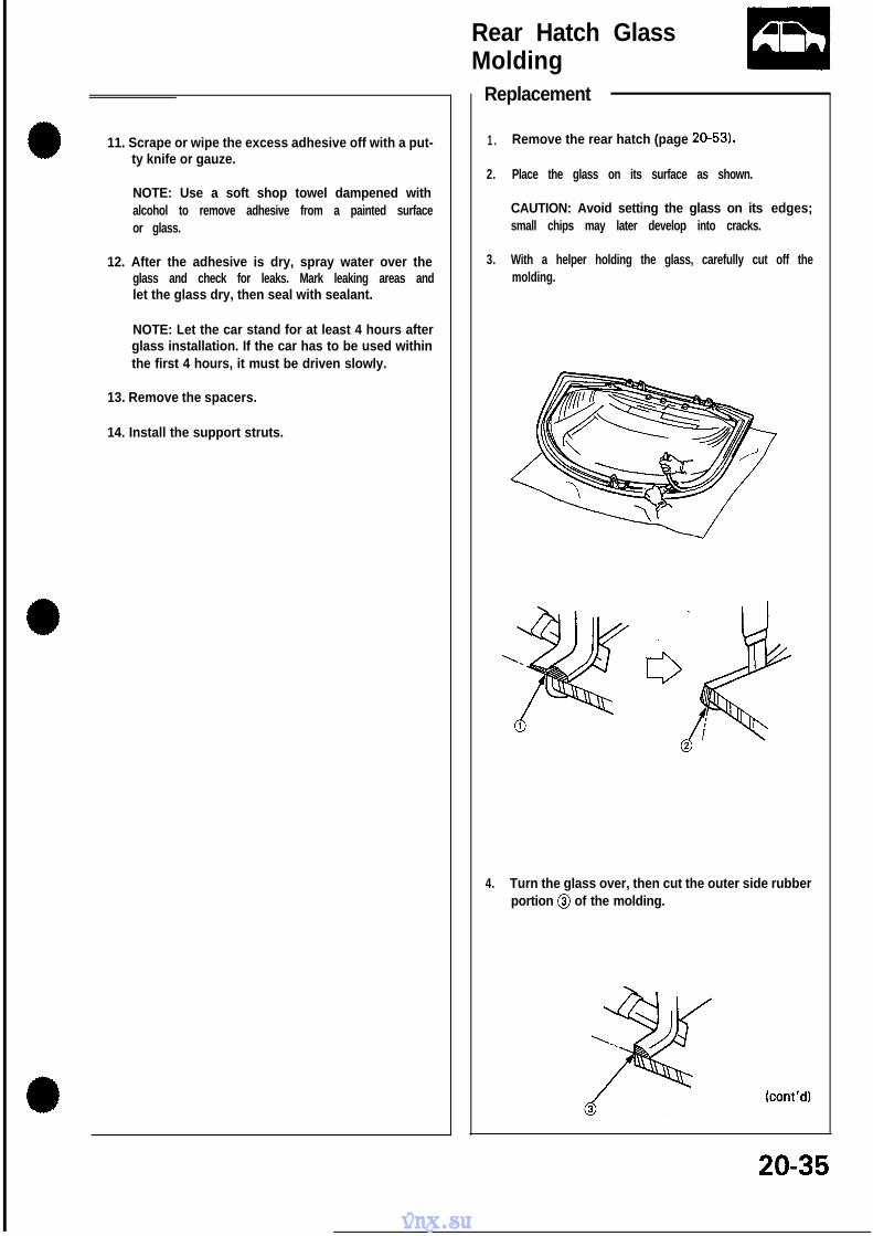
Replacement
1 . Remove the mounting bolts and lock-up control sole-
noid valve assembly.
NOTE: Be sure to remove or replace the lock-up con-+-A --I--AA wnhrmc A ad R a-z nn ac.qemhlv.vnx.su
Disconnect the 26P and 22P con-nectors from the control unit.
Measure the vol tage between D2(GRNIWHT) and A25 (BRNNVHT)terminal with the brake pedalpushed.
Repair open in GRN/WHT wlre be-Is there battery voltage? tween D2 terminal and brake light
switch.Y E S
Brake l ight signal OK.
- A26
BRNIVVHT
NOTE: View from terminal side.
14-78
I I ^^I--^ :A ..-I..-- A _ -.I ”vnx.su
Linear SolenoidTest Replacement
1 .
2.
3.
4.
5 .
6.
Remove the linear solenoid connector.
Measure the resistance between the A and B terminal.
STANDARD: 4.65 - 5.35 Q
Replace the linear solenoid if resistance is out ofspecification.
Connect the A terminal of the linear solenoid connec-tor to the battery. A clicking sound should be heard.Connect the B terminal of the linear solenoid connectorto the battery. A clicking sound should be heard.
If not, check for continuity between the AiT controlunit Al or Dl harness and body ground page 14-73.
Replace the linear solenoid assembly if there is con-tinuity between the Al or Dl and body ground.
NOTE: Select the appropriate shim when the linear sole-noid is replaced.
1 . Remove the linear solenoid and shim from the trans-mission housing.
2 . Clean the mounting surface.
3 . Measure the distance between the mounting surfaceof the linear solenoid and the throttle valve body.
Measurement ofdistance.
, , YEARSOLENOID
LINEAR SOLENOIDS H I M \
LINEAR SOLENOIDINSTALLATIONDISTANCE
THROTTLE A \VALVE BODY Measurement of distance
LINEAR SOLENOID INSTALLATION DISTANCE:23.5 - 23.7 mm (0.925 - 0.933 in)
NOTE: If the measurement of distance is 21.6 mm(0.850 in), select the shim of 2.0 mm (0.079 in) to ob-tain the installation distance of 23.6 mm (0.929 in).
(cont’d)
14-81
vnx.su
Linear Solenoid- Replacement (cont’d)
4. Select a new shim from the chart below.
NOTE: Identification color is painted on the side ofthe shim.
LINEAR SOLENOID
LINEAR SOLENOID SHIM
h 10 PART NUMBER THICKNESS COLOR
1 28252-PR9-000 1.2 m m(0.047 in)
BLACK
2 28253-PR9-000 1.4 m m(0.055 in) BROWN
3 28254-PR9-000 1.6 m m(0.063 in)
RED
4 28255-PR9-000 1.8 m m(0.071 in)
PINK
9 28260-PR9-0002.8 mm
(0.110 in)WHITE
5. Apply liquid gasket to both sides of the linearsolenoid shim as shown. Use liquid gasket Part No.08718-550000 OE.
CAUTION:0 Install the linear solenoid within 10 minute of
applying the liquid gasket.l After installation, wipe off any liquid gasket, that
squeezed out from around the linear solenoidshlm.
NOTE:l Check that the mounting surfaces are clean and
dry before applying liquid gasket. Degrease ifnecessary.
0 Apply the liquid gasket evenly.0 Do not install the parts if 10 minutes or more has
passed since you first applied the liquid gasket.If 10 minutes has passed, reapply liquid gasketafter removing the residue.
l Wait at least 30 minutes before filling with oil.
Do not apply liquid gaskethere on either side./ Apply liquid gasket
here on both side.
’ s iO.l97-X394 in)
6. Install the linear solenoid and shim to thetransmission housing.
6 x l.Omm Clean mounting surface.IO Nom \
/LINEAR SOLENOID
0-dlNGReplace.
14-82
vnx.su
A/T Speed Sensors- Replacement
1 . Remove the 6 mm bolt from the transmissionhousing and remove the A/T speed sensor.
2. Replace the O-ring with a new one beforereassembling the AK speed sensor.
6 x l.Omm12 N-m (I .2 kg-m, 9 lb-ft)
NC SPEED SEN
NM SPEED SENSOR
6xl:Omm12 N-m (1.2 kg-m, 9 lb-ft)
mO0
14-83
vnx.su
Symptom-to-Component ChartHydraulic System (cont’d)
SYMPTOM Check these items on the Check these items on thePROBABLE CAUSE LIST NOTES CHART
Engine runs, but car does not move in any gear. 1, 6, 7, 16 K, L, R, S
Car moves in R, 2 and 3, but not in D or 1. 8, 29, 44,‘48 C, M, 0Car moves in D, 2, 1, R but not in 3. 10, 31 c, L
Car moves in D, 3, 1, R but not in 2. 9, 30, 49 c, L
Car moves in D, 3, 2, 1, but not in R. 1, 11, 22, 34, 38, 39, 40 c, L, QCar moves in N. 1, 9, 478, IO, 11, 46, C, DExcessive idle vibration. 5, 17 B, K, L
Slips in all gears. 6, 7, 16 c, L, uNo engine braking in q position. 1 2 C, D, L
Slips in 1st gear. 8, 29, 44, 48 C, N, 0, USlips in 2nd gear. 9, 20, 23, 30, 49 c, L, u
Slips in 3rd gear. 10, 21, 23, 31, 44 c, L, u
Slips in 4th gear. 11, 23, 32 c, L, u
Slips in reverse gear. 11, 32, 34 C
Flares on 1-2 upshift. 3, 15 E, L, V
Flares on 2-3 upshift. 3, 15, 24, 44 E, L, VFlares on 3-4 upshift. 3, 15, 25, 44 E, L, VNo upshift, trans stays in 1st gear. 14, 19, 23 G, LNo downshift to 1st gear. 12,19 G, LLate upshift. 1 4 L, V
Erratic shifting. 14, 2 6 V
Harsh shift (up and down shifting). 2, 4, 15, 23, 24, 27, 47 A, E, H, I, L, VHarsh shift (I -2). 2, 9 C, D, VHarsh shift (2-3). 2, 10, 23, 24 C, D, H. L, VHarsh shift (3-4). 2, 11, 23, 25 C, D, I, L, V
Harsh kickdown shifts. 2, 23, 27, 28 L, v, Q
Harsh kickdown shift (2 - 1). 48 0Harsh downshift at closed throttle, 1 5 E, THarsh shift when manually shifting to a. 3 3 L
.Axle(s) slips out of trans on turns. 43, 50 L, P, QAxle(s) stuck in trans. 43 L, QRatcheting noise when shifting into R. 6, 7, 38, 39, 40 K, L, QLoud popping noise when taking off in R. 38, 39, 40 L, 0Ratcheting noise when shifting from R to P or from R 38, 39, 40, 45 L, Qto N.Noise from trans in all selector lever positions. 6, 17 K, L, QNoise from trans only when wheels are rolling. 39, 42 L, 0Gear whine, rpm related (pitch changes with shifts). 8, 41 K, L, QGear whine, speed related (pitch changes with 38, 42 L, Qspeed).
Trans will not shift into 4th in D.gear 1, 21, 28, 32 L
Lock-up clutch does not lock up smoothly. 17, 36, 37 L
Lock-up clutch does not operate properly. 2, 3, 15, 18, 35, 36, 37 E, L, VTransmission has multitude of problems shifting. 43 L, QAt disassembly, large particles of metal are found onmagnet.
14-84
vnx.su
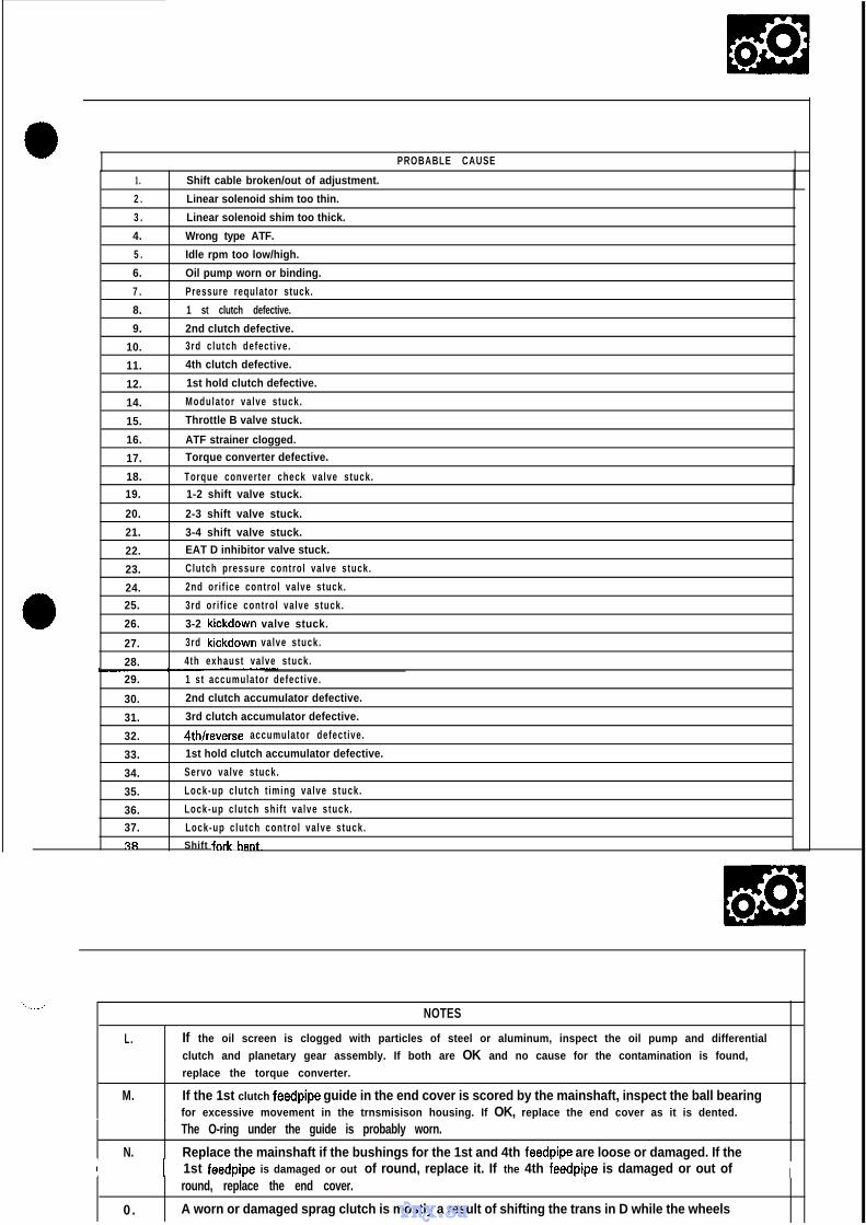
a PROBABLE CAUSE
1.
2 .
3 .
4.
5 .
6.
7 .
8.
9.
10.
11.
12.
14.
15.
16.
17.
18.
19.
20.
21.
22.
23.
24.
25.
26.
27.
28.
29.
30.
31.
32.
33.
34.
35.
36.
37.
3R
Shift cable broken/out of adjustment.
Linear solenoid shim too thin.
Linear solenoid shim too thick.
Wrong type ATF.
Idle rpm too low/high.
Oil pump worn or binding.
Pressure requlator stuck.
1 st clutch defective.
2nd clutch defective.
3rd clutch defect ive.
4th clutch defective.
1st hold clutch defective.
Modulator va lve stuck.
Throttle B valve stuck.
ATF strainer clogged.
Torque converter defective.
Torque converter check valve stuck.
1-2 shift valve stuck.
2-3 shift valve stuck.
3-4 shift valve stuck.
EAT D inhibitor valve stuck.
Clutch pressure control valve stuck.
2nd or i f ice control valve stuck.
3rd or i f ice control valve stuck.
3-2 kickdown valve stuck.
3rd kickdown valve stuck.
4th exhaust valve stuck.
1 st accumulator defect ive.
2nd clutch accumulator defective.
3rd clutch accumulator defective.
4th/reverse accumulator defect ive.
1st hold clutch accumulator defective.
Servo valve stuck.
Lock-up c lutch t iming valve stuck.
Lock-up c lutch shi f t va lve stuck.
Lock-up c lutch control va lve stuck.
Shift fnrk
-.--.NOTES
L.
M.
If the oil screen is clogged with particles of steel or aluminum, inspect the oil pump and differential
clutch and planetary gear assembly. If both are OK and no cause for the contamination is found,
replace the torque converter.
If the 1st clutch feedpipe guide in the end cover is scored by the mainshaft, inspect the ball bearingfor excessive movement in the trnsmisison housing. If OK, replace the end cover as it is dented.
The O-ring under the guide is probably worn.
N. Replace the mainshaft if the bushings for the 1st and 4th feedpipe are loose or damaged. If theI ) 1st feedpipe is damaged or out of round, replace it. If the 4th feedpipe is damaged or out of I
0 .
round, replace the end cover.
A worn or damaged sprag clutch is mostly a result of shifting the trans in D while the wheelsvnx.su
Symptom-to-Component Chart- Hydraulic System (cont’d)
The following symptoms can be causedby improper repair or assembly.
Check these items on thePROBABLE CAUSE DUETO IMPROPER REPAIR
Items on theNOTES CHART
1 Car creeps in N. 1 RI, R2 I I
I Car does not move in D. 1 R4 I I
Trans locks up in R.
Excessive drag in trans.
Excessive vibration, rpm related.
Noise with wheels moving only.
Main seal oops out.
R3, RI2
R 6 R. K
R 7
R 5
R 6 S
r Various shifting problems. 1 R9, R I O I I
Harsh upshifts. 1 RI1
I-- ~~~ PROBABLE CAUSE DUE TO IMPROPER REPAIR I
RI.
R2.
R3.
R4.
Improper clutch clearance.
Improper gear clearance.
Parking brake lever installed upside down.
Spraa clutch installed upside down.
I R5. TV- ~~ -.Reverse hub rnstalled upside down.
I R6. I Oil pump binding. IR7.
R8.
R9.
Torque converter not fully seated in oil pump.
Main seal improperly installed.
Sprinas improperlv installed.
I~ ~~RIO. I Valves improperly installed. II RI 1. I Ball check valves not installed. I
R12. Shift fork bolt not installed. I
B.
NOTES
Set idle rpm in gear to specified idle speed. If still no good, adjust motor mounts as outlined in en-gine section of service manual.
I c. 1 If the large clutch piston O-ring is broken, inspect the piston groove for rough machining. ID.
E.
G.
If the clutch pack is seized or is excessively worn, inspect the other clutches for wear and checkthe orifice control valves and throttle valves for free movement.
If throttle valve B is stuck, inspect the clutches for wear.
If the 1-2 valve is stuck closed, the transmission will not upshift. If stuck open the transmissionhas no 1st gear.
I H. If the 2nd orifice control valve is stuck, inspect the 2nd and 3rd clutch packs for wear.
I.
J.
If the orifice control valve is stuck, inspect the 3rd and 4th clutch packs for wear.
If the clutch pressure control valve is stuck closed, the transmission will not shift out of 1st gear.
K. Improper alignment of main valve body and torque convertor case may cause oil pump seizure.The symptoms are mostly an rpm-related ticking noise or a high pitched squeek.
14-86
vnx.su
Stall Speed. Test
CAUTION:l To prevent transmission damage, do not test stall speed for more than 10 seconds at a time.l Do not shift the lever while raising the engine speed.l Be sure to remove the pressure gauge before testing stall speed.
1 . Engage the parking brake and block all four wheels.
2. Connect the tachometer, and start the engine.
3. After the engine has warmed up to normal operating temperature, shift into 2 position.
4. Fully depress the brake pedal and accelerator for 6 to 8 seconds, and note engine speed.
5 . Allow 2 minutes for cooling, then repeat same test in 1, 3, D and R position.
NOTE: Stall speed test must be made only for checking the cause of trouble.
Stall Speed RPM: Specification: 1,950-2,250 rpm
TROUBLE
Stall rpm high in 2 position
PROBABLE CAUSE
l Low fluid level or oil pump outputl Clogged oil strainerl Pressure regulator valve stuck closedl Slippage of 2nd clutch
Stall rpm high in 1 position
Stall rpm high in 3 position
Stall rpm high in D position
Stall rpm high in R position
Stall rpm low in 2 position
l Slippage of 1st clutch or 1st hold clutch
l Slippage of 3rd clutch
l Slippage of 1 st clutch or 1 st gear one-way clutch
l Slippage of 4th clutch
l Engine output lowl Torque converter one-way clutch slipping
14-89
vnx.su
Pressure- Testing
l While testing, be careful of the rotating rear wheels.l Make sure lifts are placed properly.
CAUTION:l Before testing, be sure the transmission fluid is filled
to the proper level.l Warm up the engine before testing.
1 .
2.
3.
4 .
5.
Raise the car. (See page l-6.)
Warm up the engine, then stop the engine andconnect a tachometer.
Connect the oil pressure gauge to each inspectionhole(s).18 N-m (1.8 kg-m, 12 lb-ft) ,
CAUTION: Connect the oil pressure gaugesecurely, being sure not to allow dust and otherforeign particles to enter the inspection hole.
Start the engine and measure the respective pressureas follows.0 Line Pressure/Clutch Pressure0 Clutch Low/High Pressurel Throttle B Pressure
Install a new washer and the sealing bolt in theinspection hole and tighten to the specified torque.18 N-m (I .8 kg-m, 12 lb-ft)
NOTE: Do not reuse old aluminum washers.
l Line Pressure/Clutch Pressure Measurement
-1. Allow the rear wheels to rotate freely.
-2. Run the engine at 2,000 rpm.
-3. Shift the select lever as shown on the chart onthe next page.
-4. Measure each clutch pressure.
m While testing, be careful of the rotatingrear wheels.
vnx.su
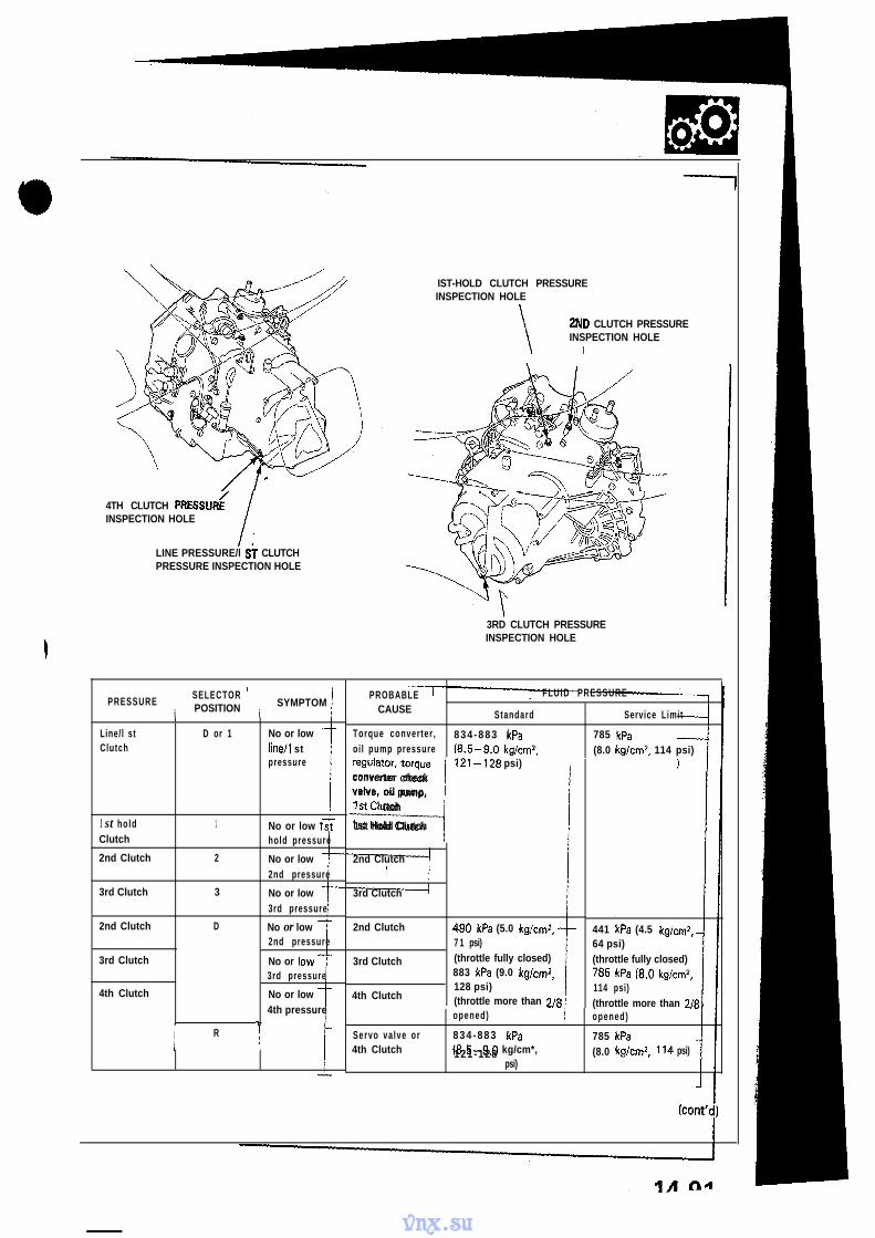
4TH CLUTCH PRESSUR<INSPECTION HOLE
LINE PRESSURE/l Si CLUTCHPRESSURE INSPECTION HOLE
PRESSUREi
SELECTORPOSITION i
SYMPTOM
Line/l stClutch
1
D or 1 No or lowline/l stpressure
1 st hold 1Clutch
No or low 1sthold pressure
2nd Clutch 2 No or low2nd pressure
3rd Clutch 3 No or low3rd pressure
2nd Clutch D No or low2nd pressure
3rd Clutch No or low3rd pressure
4th Clutch No or low4th pressure
, ‘I
I RI
IST-HOLD CLUTCH PRESSUREINSPECTION HOLE
\
2ND CLUTCH PRESSUREINSPECTION HOLE
I
\\
3RD CLUTCH PRESSUREINSPECTION HOLE
PROBABLE FLUID PRESSURE
CAUSE Standard Service Limit
Torque converter , 834 -883 kPaoi l pump pressure
785 kPa(8.5-9.0 kg/cmz, (8.0 kg/cm”, 114 psi)
regulator, torque
------I121-128 psi)
converter checkvalve, o i l pump,1st Clutch
1st Hold Clutch
2nd Clutch
3rd Clutch
2nd Clutch
3rd Clutch
4th Clutch
Servo va lve or4th Clutch
490 kPa (5.0 kg/cm2,7 1 psi)(throttle fully closed)883 kPa (9.0 kg/cm2,128 psi)(throttle more than 2/Sopened)
834 -883 kPa(8.5-9.0 kg/cm*,121 -128
psi)
441 kPa (4.5 kg/cmz,64 psi)(throttle fully closed)785 kPa (8.0 kg/cm2,114 psi)(throttle more than 2/8opened)
785 kPa(8.0 kg/cm*, 114 psi)
Icont’d)
vnx.su
Pressure
r Testing (cont’d)
0 Clutch Low/High Pressure Measurement
-1. Allow the rear wheels to rotate freely.
-2. Start the engine and let it idle.
-3. Shift the select lever to D position.
-4. Slowly press down the accelerator pedal to in-crease engine rpm until pressure is indicated onthe oil pressure gauge. Then release the acceler-ator pedal, allowing the engine return to an idle,and measure the pressure reading.
While testing, be careful of the rotat-ing rear wheels.
-5, Repeat step -4 for each clutch pressure beinginspected’.
No or low 3rd Clutch 71-128 psi) with accelerator pedalvaries with throttle released
3rd pressureopening 785 kPa
No or low 4th Clutch (8.0 kg/cm2, 1 I4 Ps’4th pressure with accelerator ped
more than 218 opens
-6. With the engine idling, press down the acceler-ator pedal approximately l/2 of its possible trav-el and increase the engine rpm until pressure isindicated on the gauge, measure the highestpressure reading obtained.
nmEm While testing, be careful of the rotat-ing rear wheels.
-7. Repeat step -6 for each clutch pressure beinginspected.
2ND CLUTCH PRESSUREINSPECTION HOLE
~RD CLUTCH PRESSUREINSPECTION HOLE
vnx.su
mO0
0 Throttle B Pressure Measurement
-1. Allow the rear wheels to rotate freely. LINEAR SOLENOIDI
-2. Disconnect the linear solenoid connector.
-3. Shift the select lever to D position.
-4. Run the engine at 1,000 rpm.
-5. Measure full closed throttle B pressure.
w While testing, be careful of the rotat-ing rear wheels.
-6. Connect battery voltage to the linear solenoid.LINkAl SOLENOID
-7. Measure full opened throttle B pressure. CONNECTOR
w While testing, be careful of the rotat-ing rear wheels.
THROTTLEPRESSUREINSPECT10
\LINEAR SOLENOID
PRESSURE
Throttle B
SELECTOR FLUID PRESSUREPOSITION SYMPTOM PROBABLE CAUSE
Standard Service Limit
D Pressure too Linear Solenoid O - 1 5 kPa O - 1 5 kPahigh (O-O. 15 kg/cm2, 10-O. 15 kg/cm*,
O-2 psi) O-2 psi)
No or low Faulty throttle B 598-657 kPa 598-657 kPapressure valve (6.1-6.7 kg/cm2, (6.1-6.7 kg/cm2,
87-95 psi) 87-95 psi)
14-93
vnx.su
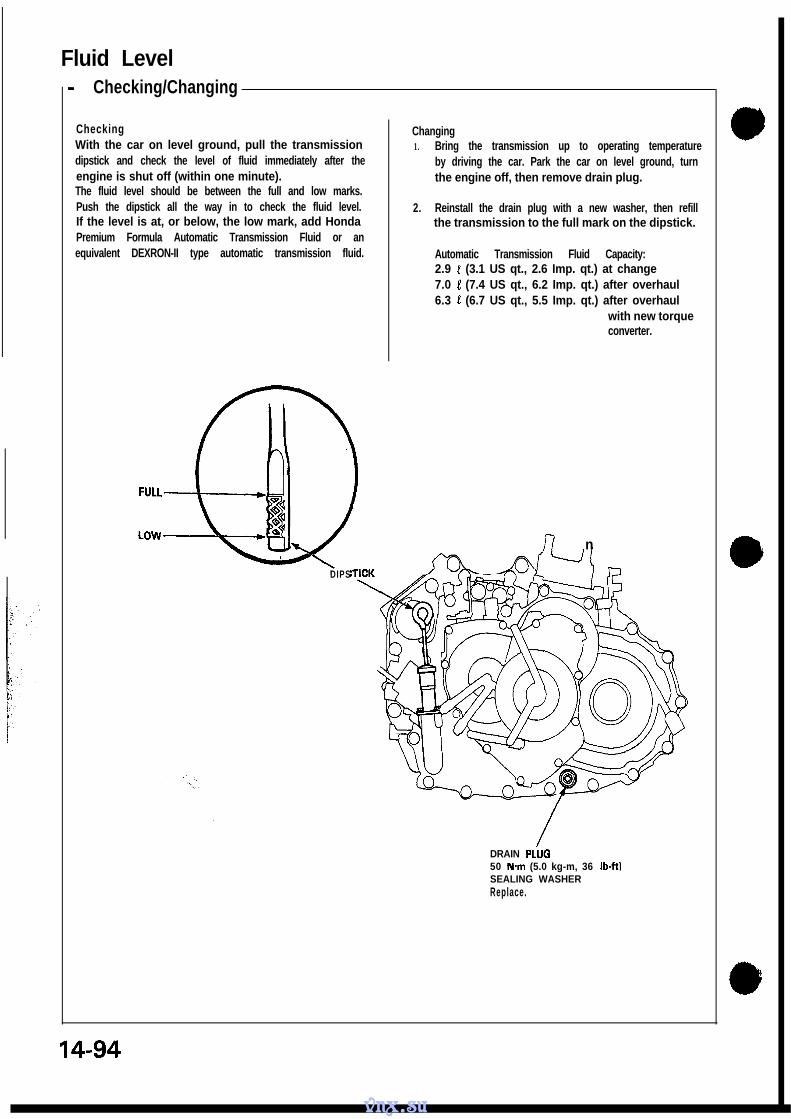
Fluid Level- Checking/Changing
CheckingWith the car on level ground, pull the transmissiondipstick and check the level of fluid immediately after theengine is shut off (within one minute).The fluid level should be between the full and low marks.Push the dipstick all the way in to check the fluid level.If the level is at, or below, the low mark, add HondaPremium Formula Automatic Transmission Fluid or anequivalent DEXRON-II type automatic transmission fluid.
FULL
Changing1. Bring the transmission up to operating temperature
by driving the car. Park the car on level ground, turnthe engine off, then remove drain plug.
2. Reinstall the drain plug with a new washer, then refillthe transmission to the full mark on the dipstick.
Automatic Transmission Fluid Capacity:2.9 L (3.1 US qt., 2.6 Imp. qt.) at change7.0 1 (7.4 US qt., 6.2 Imp. qt.) after overhaul6.3 L (6.7 US qt., 5.5 Imp. qt.) after overhaul
with new torqueconverter.
17 n
DIPS
DRAIN PLiJG50 Mm (5.0 kg-m, 36 lb-ft)SEALING WASHERReplace.
14-94
vnx.su
14-95
vnx.su
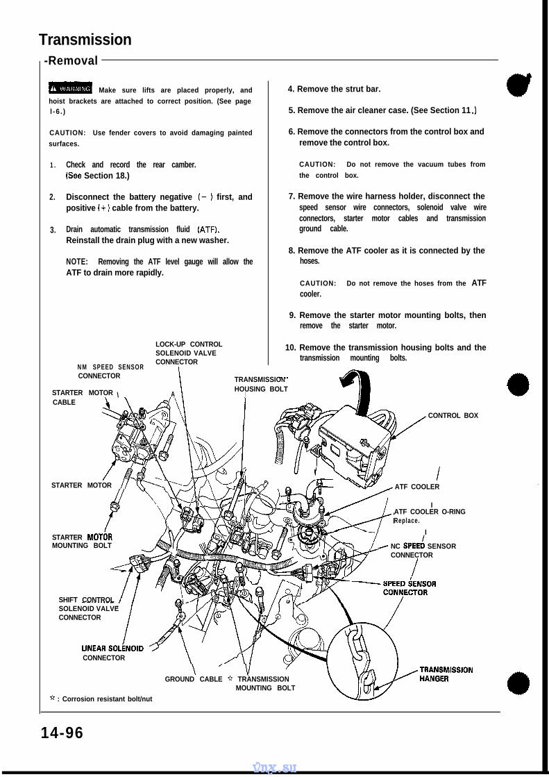
Transmission-Removal
m Make sure lifts are placed properly, and
hoist brackets are attached to correct position. (See pagel -6 . )
CAUTION: Use fender covers to avoid damaging painted
surfaces.
1 .
2.
3.
Check and record the rear camber. CAUTION: Do not remove the vacuum tubes from
(See Section 18.) the control box.
Disconnect the battery negative (- 1 first, andpositive (+ 1 cable from the battery.
Drain automatic transmission fluid (ATF).Reinstall the drain plug with a new washer.
NOTE: Removing the ATF level gauge will allow theATF to drain more rapidly.
LOCK-UP CONTROLSOLENOID VALVE
N M SPEED SENSORCONNECTOR
I
4. Remove the strut bar.
5. Remove the air cleaner case. (See Section 11 .I
6. Remove the connectors from the control box andremove the control box.
7. Remove the wire harness holder, disconnect thespeed sensor wire connectors, solenoid valve wireconnectors, starter motor cables and transmissionground cable.
8. Remove the ATF cooler as it is connected by thehoses.
CAUTION: Do not remove the hoses from the ATFcooler.
9. Remove the starter motor mounting bolts, thenremove the starter motor.
10. Remove the transmission housing bolts and thetransmission mounting bolts.
CONNECTOR
\
TRANSMISSION
STARTER MOTOR HOUSING BOLTA I
CABLE
CONTROL BOX
STARTER MOTOR // ’
STARTER MOTGRMOUNTING BOLT
CONNECTOR
ATF COOLER
IATF COOLER O-RINGReplace.
I
#&Q //- NC SPEED SENSORCONNECTOR
I
SHIFT CONTROLSOLENOID VALVECONNECTOR
\ ’ \IGROUND CABLE * TRANSMISSION
MOUNTING BOLT
* : Corrosion resistant bolt/nut
14-96
vnx.su
11. Remove the parking brake cable holders from the rear beam rod.12. Remove the rear beam rod.13. Remove the front exhaust pipe A.
*: Corrosion resistant bolt/nut
SELF-LOCKING NUTReplace.
PARKING BRAKECABLE HOLDER
GASKETReolace.
\SE‘LF-LOCKING NUTReplace.
14” r\ FkONT EXHAUST
y ID* P I P E A
*
14. Remove the parking brake cable holder and the anti-lock brake system sensor wire clamp.15. Remove the castle nut and separate the control arm from the knuckle (See Section 18).16. Remove the damper fork bolt.17. Remove the castle nut and separate the lower control arm from the knuckle (See Section 18).18. Remove the right driveshaft from the intermediate shaft.
19. Remove the intermediate shaft heat cover and the intermediate shaft mounting bolts.20. Pry the intermediate shaft out of the differenctial. Pull and remove it.
NOTE:0 Coat all precision finished surfaces with clean engine oil or grease.l Tie plastic bags over the driveshaft ends.
INTERMEDIATE SHAFT\?-a
SET RINGReolace.
INTERMEDIATE‘HEAT COVER
SHAFT
INTERMEDIATE SHAFT---IIS
31. Remove the parking brake cable holder and the anti-lock brake system sensor wire clamp.32. Make a reference mark on the flange of the adjusting bolt, adjusting cam and lower control arm.33. Remove the castle nut and separate the control arm from the knuckle (See Section 18).34. Remove the damper fork bolt.35. Remove the bolts and lower arm from the side beam.36. Pry the driveshaft out of the differential. Pull and remove it.
NOTE:0 Coat all precision finished surfaces with clean engine oil or grease.l Tie plastic bags over the driveshaft ends.
DAMPER FORK BOLT -&fl ‘ONTRoL ARM
w SIDE B E A M
LOWER CONTRbLARM
ADJUSTINGBOLT
ADJUSTING CAM
14-98
vnx.su
a/-
37. Remove the one bolt of the upper arm mounting bolts,38. Remove the shift cable cover and shift cable holder.39. Remove the shift cable from the control lever.40. Remove the torque converter cover and then remove the drive plate bolts.
DRIVE PLATEUPPER CONTROLARM DAMPER
UPPEB ARM MOUNTINGBOLT
aa CABLE
TORQUE CONVERTERSHIFT CABLE
COVERHOLDER
SHIFT CABLE
41. Attach a chain hoist to the transmission hangers.42. Place a jack under the transmission and raise the transmission just enough to take weight off of the mounts.43. Remove the front engine mounting bolts on the transmission side and retighten the bolt on the engine side.
CAUTION: Loosen the front engine mounting bolt on the engine side, but do not remove it. After removing the
two bolts on the transmission side, be sure to retighten the bolt on the engine side.44. Remove the rear transmission mounting bolts.45. Remove the transmission housing mounting bolts..46. Pull the transmission away from the engine until it clears the dowel pins, then lower it on the transmission jack.
ION HOUSINGBOLT
REAR TRAMOUNT
FRONT ENGINE MOUNTINGBOLT [Engine side)
ENGINE MOUNTING(Transmission side)
REAR TRANSMISSIONMOUNTING BOLT
ONT ENGINE MOUNTTRANSMISSION JACK
TRANSMISSION HOUSING MOUNTING BOLT
14-99
vnx.su
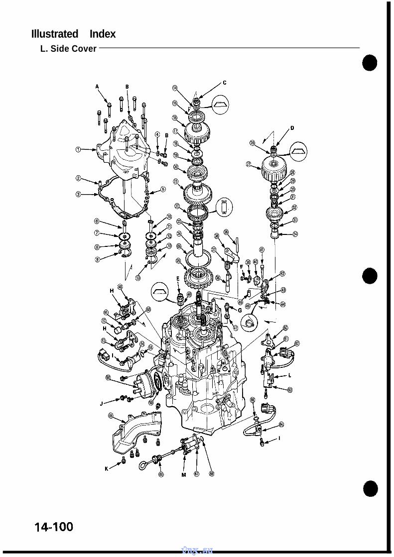
Illustrated IndexL. Side Cover
14-100
vnx.su
l!!!!aO0
L. SIDE COVERDOWEL PINGASKET Replace.SEALING WASHER Replace.
O-RING Replace.IST-HOLD CLUTCH FEED PIPEO-RING Replace.FEED PIPE FLANGESNAP RINGIST CLUTCH FEED PIPEO-RING Replace.FEED PIPE FLANGESNAP RINGDISC SPRING Replace.BALL BEARINGIS+-HOLD CLUTCH ASSEMBLYO-RING Replace.THRUST WASHERTHRUST NEEDLE BEARINGIST-HOLD CLUTCH HUBCOUNTERSHAFT IST GEARONE-WAY CLUTCHNEEDLE BEARINGCOUNTERSHAFT IST GEAR COLLARPARKING GEARDISC SPRING Replace.IST CLUTCH ASSEMBLYO-RING Replace.THRUST WASHERTHRUST NEEDLE BEARINGNEEDLE BEARINGMAINSHAFT IST GEARTHRUST WASHERMAINSHAFT IST GEAR COLLARPARKING BRAKE PAWL STOPPER
NOTE:l Clean all parts thoroughly in solvent or carburetor cleaner and dry with compressed air.0 Blow out all passages.l Cut the lock tab and raise it, then remove the locknut of each shaft.0 Countershaft locknut has left-hand threads.
1 . Remove the speed sensor cover, then reinstall three bolts around the driveshaft oil seal.CAUTION: Do not damage the driveshaft oil seal lip.
2. Slip the special tool onto the mainshaft and engage the parking brake pawl with the parking gear.
3. Remove the transmission L. Side Cover in the following numbered sequence.NOTE: Remove the special tool from the mainshaft after removing the locknuts.
Reinstall 3 bolts aroundthe driveshaft oil seal.
CAUTION: Protect the lip of thedriveshaft oil seal by reinstalling threebolts, after removing the speed sensorcover.
DRIVERSHAFTOIL SEAL
SPEED SENSORCOVER BOLT
07924-PJ40000
NOTE: Using a chisel, cut the lock tab. Fryit up and then remove the locknut from eachshaft.
14-106
vnx.su
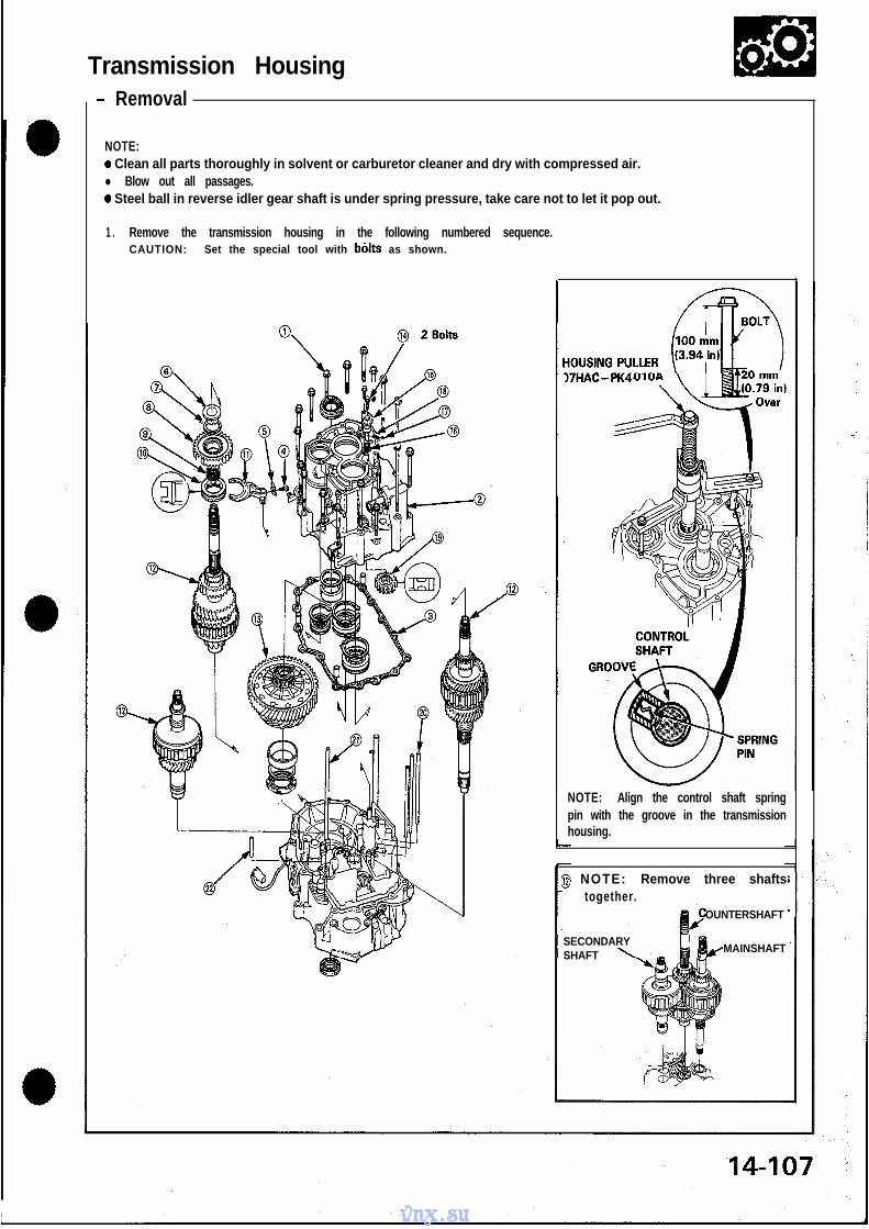
Transmission Housing l!!!!a00- Removal
NOTE:a Clean all parts thoroughly in solvent or carburetor cleaner and dry with compressed air.l Blow out all passages.0 Steel ball in reverse idler gear shaft is under spring pressure, take care not to let it pop out.
1 . Remove the transmission housing in the following numbered sequence.CAUTION: Set the special tool with b6lts as shown.
)7HAC-PK4
NOTE: Align the control shaft springpin with the groove in the transmissionhousing.
a NOTE: Remove three shaftstogether.
OUNTERSHAFT
SECONDARYSHAFT
MAINSHAFT
vnx.su
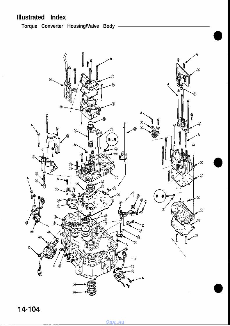
Valve Body- Removal
NOTE:a Clean all parts thoroughly in solvent or carburetor cleaner and dry with compressed air. Blow out all passages.a Accumulator covers are spring loaded; to prevent stripping the threads in the torque converter housing, press down
on the accumulator covers while unscrewing the bolts in a crisscross pattern.
1 . Remove the valve body in the following numbered sequence.
CAUTION: Do not use a magnet to remove the check balls: it may magnetize the balls.
@4 Bo l ts
\6 2 BoltsP &aReplace. Q
!RF Replace.
14-108
vnx.su
Valve !!!!!a00- Assembly 1
NOTE: Coat all parts with ATF before assembly.
1. Install the valve, valve spring and cap in the valvebody and secure with the roller.
ROLLER
/
VALV
ROLLER
/
CAP
I
2. Set the spring in the valve and install it in the valvebody. Push the spring in with a screwdriver then in-stall the spring seat.
SPRING
VALVE BODY\\
3. Set the spring in the valve and install it in the valvebody.Install the spring with a screwdriver, then install thevalve cap with the cutout aligned with the screw-driver.
VALVE BODY
VALVE SPRING’CAP SCREinrDRlVER
_’
f:‘:_
14409
vnx.su
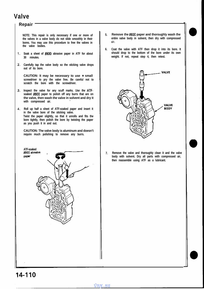
Valve
NOTE: This repair is only necessary if one or more ofthe valves in a valve body do not slide smoothly in theirbores. You may use this procedure to free the valves inthe valve bodies.
Soak a sheet of #600 abrasive paper in ATF for about30 minutes.
Carefully tap the valve body so the sticking valve dropsout of its bore.
CAUTION: It may be necessary to use a smallscrewdriver to pry the valve free. Be careful not toscratch the bore with the screwdriver.
Inspect the valve for any scuff marks. Use the ATF-soaked #600 paper to polish off any burrs that are onthe valve, then wash the valve in solvent and dry itwith compressed air. .
Roll up half a sheet of ATF-soaked paper and insert itin the valve bore of the sticking valve.Twist the paper slightly, so that it unrolls and fits thebore tightly, then polish the bore by twisting the paperas you push it in and out.
CAUTION: The valve body is aluminum and doesn’trequire much polishing to remove any burrs.
ATF-soakedE$abrasive ,
Repair
5. Remove the #600 paper and thoroughly wash theentire valve body in solvent, then dry with compressedair.
6. Coat the valve with ATF then drop it into its bore. Itshould drop to the bottom of the bore under its ownweight. If not, repeat step 4, then retest.
7. Remove the valve and thoroughly clean it and the valvebody with solvent. Dry all parts with compressed air,then reassemble using ATF as a lubricant.
vnx.su
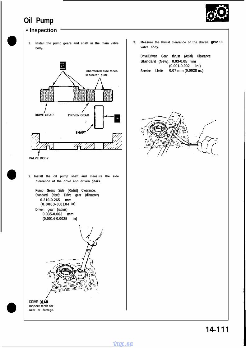
Oil Pump- Inspection
1 . Install the pump gears and shaft in the main valve
body.
Chamfered side facesseparator plate
DRIVE GEAR DRIVEN GEAR
VALVE BODY
2. Install the oil pump shaft and measure the side
clearance of the drive and driven gears.
Pump Gears Side (Radial) Clearance:Standard (New): Drive gear (diameter)
3. Measure the thrust clearance of the driven gear-to-
valve body.
Drive/Driven Gear thrust (Axial) Clearance:Standard (New): 0.03-0.05 mm
(0.001-0.002 in.)Service Limit: 0.07 mm (0.0028 in.)
vnx.su
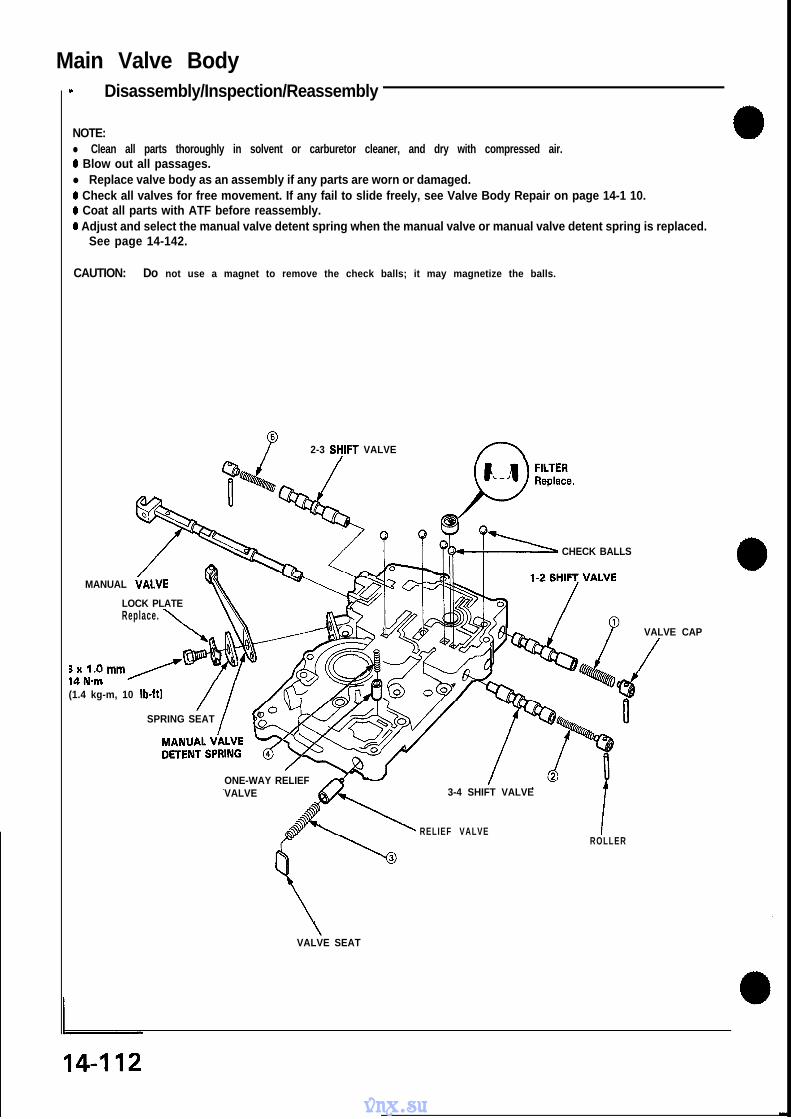
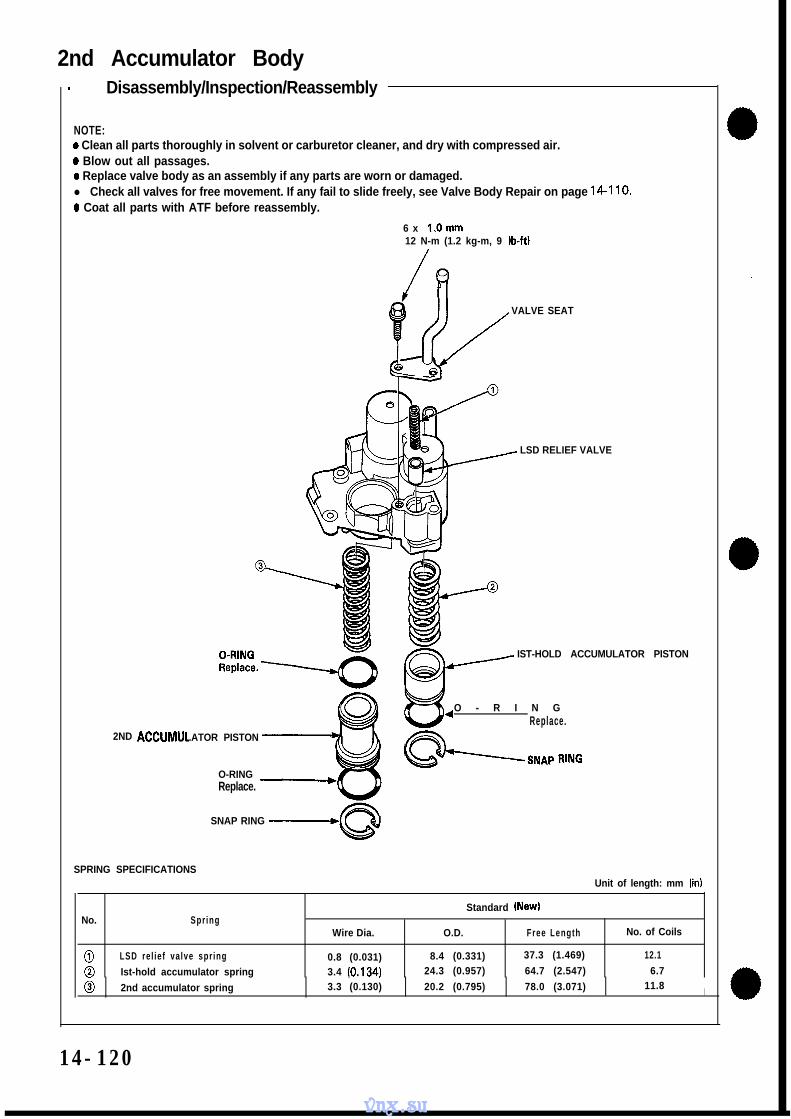
Main Valve Body- Disassembly/Inspection/Reassembly
NOTE:l Clean all parts thoroughly in solvent or carburetor cleaner, and dry with compressed air.0 Blow out all passages.l Replace valve body as an assembly if any parts are worn or damaged.0 Check all valves for free movement. If any fail to slide freely, see Valve Body Repair on page 14-1 10.0 Coat all parts with ATF before reassembly.0 Adjust and select the manual valve detent spring when the manual valve or manual valve detent spring is replaced.
See page 14-142.
CAUTION: Do not use a magnet to remove the check balls; it may magnetize the balls.
5P 2-3 StjIFT VALVE
CHECK BALLS
MANUAL VALVE
LOCK PLATEReplace.\ VALVE CAP
/BxlOmm
14Nin(1.4 kg-m, 10 lb-ft)/
SPRING SEATI h
0C
ONE-WAY RELIEF
iROLLER
VALVE 3-4 SHIFT VALVE
RELIEF VALVE
VALVE SEAT
vnx.su
TORQUE CONVECHECK VALVE
BODYSectional view.
CHECK BALL
SPRING SPECIFICATIONSI Ini+ .4 I---*I... -‘TI ,jl,
No. SpringStandard (New)
Wire Dia. O.D. Free Length No. of Coils
al l-2 shift spring 0.90 (0.035) 8.62-313-4 shift spring (0.339) 40.4 (1.591) 14.50.80 (0.031) 7.0Relief valve spring (0.276) 43.7 (1.720) 21.21.10 (0.043) 8.4One-way relief valve (0.331) 44.4 (1.748) 19.50.90 spring (0.035) 6.42-313-4 shift spring (0.252) 25.1 (0.988) 11.90.80 (0.031) 7.0Torque converter check (0.276) 43.7v a l v e (1.720) 21.2
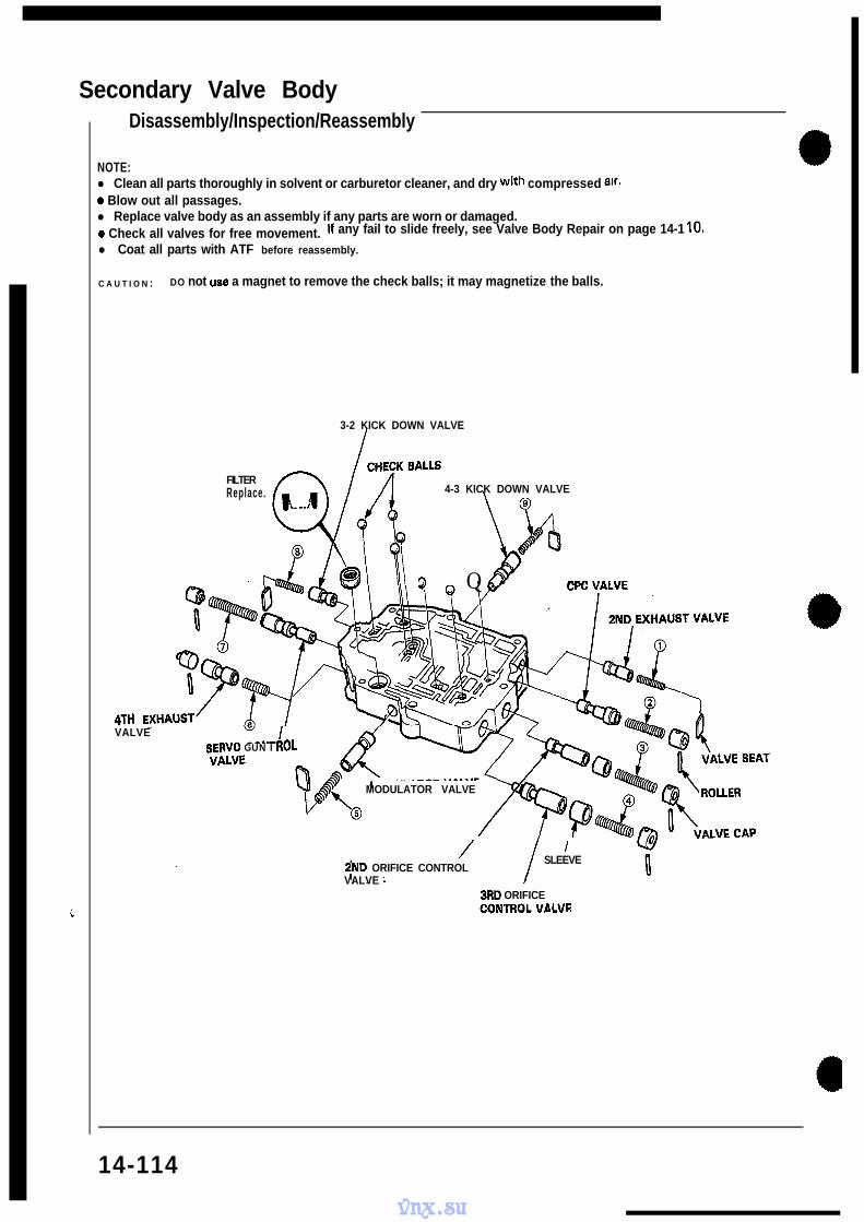
NOTE:l Clean all parts thoroughly in solvent or carburetor cleaner, and dry with compressed air.0 Blow out all passages.l Replace valve body as an assembly if any parts are worn or damaged.0 Check all valves for free movement. If any fail to slide freely, see Valve Body Repair on page 14-1 IO.
l Coat all parts with ATF before reassembly.
C A U T I O N : DO not use a magnet to remove the check balls; it may magnetize the balls.
4THVALVE I- --..--A.
3-2 KICK DOWN VALVE
FILTERReplace. 4-3 KICK DOWN VALVE
Q Q - - -
aCRV0 GUN I I(UL
MODULATOR VALVE
/ I2ND ORIFICE CONTROL
SLEEVE
VALVE3RD ORIFICE
VAI VF
14-114
vnx.su
2ND CHECKBALL
\ CHECK BALLS
CHECK B
SPRING SPECIFICATIONS
rNo. Spring
2nd exhaust valve springCPC valve spring2nd orifice control valve spring
0,3rd orifice control valve spring
@‘Wodulator valve spring
?I4th exhaust valve spring
FServo control valve spring3-2 kick down valve spring4-3 kick down valve spring
I t”i!jzan a\\ parts thoroughly in solvent or carburetor cleaner,and dry with compressed air.
0 glow out all passages.. Replace valve body as an assembly if any Parts are worn Or dama9ed.
0 Check all valves for free movement.If any fail to slide freely, sea Valve Body Repair on page 14 110.
l Coat all parts with ATF before reassembly.I * R.mlace the O-rings.
0~ l.Omm12 Nrn(1.2 kg-m, 9 lb-ftl
\ ACCUMULATOR
S E R V OB A S E
6xl.Omm12 Nvn (1.2 kg-m, 9 lb-ft)
/
Replace.
ATF MAGNET
6 x l.Omm
SEP.-i ?a2r!!!!! - 0 Ihe++\
ERVO VALVE_. _ _ . . _ -_,-.
~RD ACCUMULATOR
1ST ACCUMULATOR--^-A.,lW5 I UN
Replace.
4TH ACCUMLhORPISTON
.ATE
vnx.su
m0 0
SPRING SPECIFICATIONSUnit of length: mm (in)
Standard (New)No. Spring
Wire Dia. O.D. Free Length No. of Coils
0 Throttle valve B spring 0.9 (0.035) 7.1 (0.280) 29.0 (1.142) 12.60 3rd accumulator spring 3.2 (0.126) 19.0 (0.748) 88.6 (3.488) 14.30 4th accumulator spring 3.0 (0.118) 18.0 (0.709) 84.5 (3.327) 12.80 1 st accumulator spring 2.3 (0.091) 20.0 (0.787) 104.6 (4.118) 14.8
NOTE:0 After disassembly of the ATF strainer, check that it is in good condition, and the inlet opening is not clogged.
Replace the strainer with a new one if it is clogged or damaged.0 The strainer can be reused if it is not clogged. Clean the inlet opening thoroughly with compressed air before reinstall-
NOTE:l Clean all parts thoroughly in solvent or carburetor cleaner, and dry with compressed air.0 Blow out all passages.0 Replace valve body as assembly if any parts are worn or damaged.0 Check all valves for free movement. If any fail to slide freely, see Valve Body Repair on page 14-110.
Hold the regulator spring cap in place while removing the lock bolt. Once the bolt is removed, release the springcap slowly.
CAUTION: The regulator spring cap can pop out when the lock bolt is removed.
Reassembly is in the reverse order of disassembly.
NOTE:l Coat all parts with ATF.0 Align the hole in the regulator cap with the hole in the valve body, press the spring cap into the body and tighter
the lock bolt. c
REGULATOR SPRING CAP
VALVE
ROLLER
JR PAD
LOCK-UP CONTROL
REGULATOR VALVE
COOLER RELIEFVALVE
- -6 x l O m m12Nin(1.2kgm 9Ib-ft)- I
SPRING SPECIFICATIONS
-
No. Spring
g
0c90-
Stator reaction springRegulator valve spring A
Regulator valve spring BCooler relief valve springL/C control spring
NOTE:0 Clean all parts thoroughly in solvent or carburetor cleaner, and dry with compressed air.l Blow out all passages.0 Replace valve body as an assembly if any parts are worn or damaged.0 Check all valves for free movement. If any fail to slide freely, see Valve Body Repair on page 14-1 IO.0 Coat all parts with ATF before reassembly.
LOCK-UP TIMING VALVE B
LOCK-UP SHIFT VALVE
C A P
ROLLER
SPRING SPECIFICATIONSUnit of length: mm (inI
Standard (New)No. Spr ing
Wire Dia. O.D. Free Length No. of Coils
0 Lock-up shi f t va lve spr ing 1 .o (0.039) 8.6 (0.339) 51.3 (2.0201 19.8
0 Lock-up t iming va lve B spr ing 0.8 (0.031) 5.6 (0.220) 27.8 (1.094) 16.4
NOTE:0 Clean all parts thoroughly in solvent or carburetor cleaner, and dry with compressed air.0 Blow out all passages.0 Replace valve body as an assembly if any parts are worn or damaged.l Check all valves for free movement. If any fail to slide freely, see Valve Body Repair on page 14-110.0 Coat all parts with ATF before reassembly.
MAINSHAFTCheck spl ines for excessivewear or damage.Check bearing surface forscoring, scratches or excessivew e a r .
\
SNAP YNG
THRUST NEEDLEwAsHER\l&jqJ
BEARING
-1ST GEAR
I-THRUST WASHER
HRUST WASHERTHRUST NEEDLEBEARING
4TH CLUTCH
SEAL RINGS
NEEDLE BEARING
SET RING
14-121
vnx.su
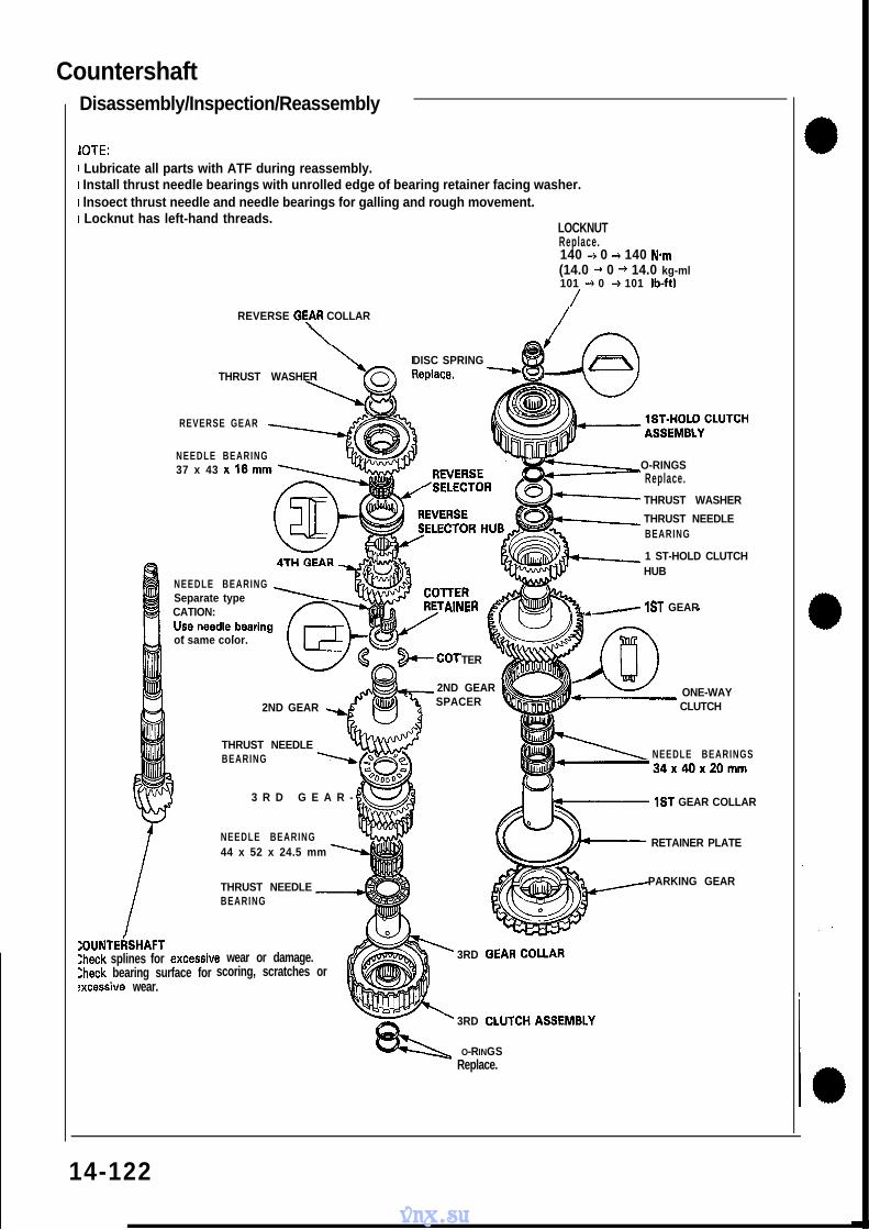
CountershaftDisassembly/Inspection/Reassembly
JOTE:1 Lubricate all parts with ATF during reassembly.1 Install thrust needle bearings with unrolled edge of bearing retainer facing washer.r lnsoect thrust needle and needle bearings for galling and rough movement.r Locknut has left-hand threads.
CLUTCH DISCSStandard thickness:1.94 mm (0.076 in1 --I+Y
CLUTCH END PLATE ’ -b
SNAP RING 4
3RD CLUTCH
~-SNAP RING
CLUTCH END PLATE
-CLUTCH DISCSStandard thickness:1.94 mm (0.076 in)
CLUTCHPLATESStandard thickness:2.0 mm (0.079 in)
w CIRCLiPm/SPRlNG RETAINER
uc RETURN SPRING
--7I/
CLUTCH PISTON
io”” :z?
/ C L U T C H D R U M
(cont’d)
14-129
vnx.su
CLUTCH DRUM \ /
SPRING RETAINER
ClRCLlP s63
CLUTCH PLATESStandard thickness: \2.3 mm (0.091 in)
O-RINGSReplace.
CLUTCH PISTON ,
ClutchIllustrated Index
2ND CLUTCH
CLUTCH END PLATE \
SNAP RING
CLUTCH DISCS, Standard th ickness:
1.94 mm (0.076 in)
vnx.su
a
a
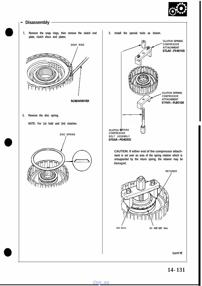
- Disassembly
1. Remove the snap rings, then remove the clutch endplate, clutch discs and plates.
SNAP RING
2. Remove the disc spring.
NOTE: For 1st hold and 2nd clutches
DISC SPRING
I
3. Install the special tools as shown.
CLUTCH
CLUTCH SPRINGCOMPRESSORATTACHMENT07LAE-PX40100
CLUTCH SPRINGCOMPRESSORATTACHMENT07HAE-PL50100
‘RING lh!COMPRESSOR wBOLT ASSEMBLY07GAE-PG40200
CAUTION: If either end of the compressor attach-ment is set over an area of the spring retainer which isunsupported by the return spring, the retainer may bedamaged.
RETAINER/
Set here. DO not set here.
(cont’d)
14-131
vnx.su
ClutchDisassembly (cont’d)
4.
5.
Compress the clutch return spring.
Remove the circlip. Then remove the special tool,spring retainer and return spring.
6. Wrap a shop rag around the clutch drum and apply airpressure to the oil passage to remove the piston. Placea finger tip on the other end while applying airpressure.
OIL PASSAGE COMPRESSED AIR
\
HOSE NOZZLEOSHA-Approved 30 psitype only.
/
a
a
a14-132
vnx.su
- Reassembly
NOTE:0 Clean all parts thoroughly in solvent or carburetor clean-
er, and dry with compressed air.0 Blow out all passages.0 Lubricate all parts with ATF before assembly.
1 . install a new O-ring on the clutch piston.
2 . Be sure that the disc spring is securely staked.NOTE: For Ist, 3rd and 4th clutches
q O-RINGSn
CLUTCH PISTON
O-RING
3 . Install the piston in the clutch drum. Apply pressureand rotate to ensure proper seating.
NOTE: Lubricate the piston O-ring with ATF before in-stalling.
CAUTION: Do not pinch O-ring by installing thepiston with force.
PISTON
CLUTCH DRUM
4. Install the return spring and spring retainer and positionthe circlip on the retainer.
CIRCLIP
/
RETURN-SPRING
(cont’d)
14-133
vnx.su
ClutchReassembly (cont’d)
5. Install the special tools as shown.
CLUTCH SPRING/ COMPRESSOR
ATTACHMENT07LAE-PX40100
L
CLUTCH SPRINGCOMPRESSORATTACHMENT07HAE-PL50100
ICLUTCH SPRING -COMPRESSORBOLT ASSEMBLY07GAE-PG40200
CAUTION: If either end of the compressor attach-ment is set over an area of the spring retainerwhich is unsupported by the retainer spring, the re-tainer may be damaged.
RETAINER
set here. Do not set here.
6. Compress the clutch return spring.
7. Install the circlip.
8. Remove the special tools.
14-l 34
vnx.su
9. install the disc spring.
NOTE:0 For 1st hold and 2nd clutchesl Install the disc spring in the right direction.
DISC SPRING
10. Soak the clutch discs thoroughly in ATFfor a minimumof 30 minutes.
11. Starting with a clutch plate, alternately install theclutch plates and discs. Install the clutch end platewith flat side toward the disc.
NOTE: Before installing the plates and discs, makesure the inside of the clutch drum is free of dirt or otherforeign matter.
CLUTCH END PLATE
LUTCI-I DISC
12. Install the snap ring
SCREWDRIVER
\
SNAP RING
(cont’d)
vnx.su
ClutchReassembly (cont’d)
13. Measure the clearance between the clutch end plateand top disc with a dial indicator. Zero the dial indicatorwith the clutch end plate lowered and lift it up to thesnap ring. The distance that the clutch end platemoves is the clearance between the clutch end plateand top disc.NOTE: Measure at three locations.
End Plate-to-Top Disc Clearance:
Clutch
1 s t2nd3rd4th
1 St-Hold
Service Limit
0.65 - 0.85 mm (0.026 - 0.033 in)0.75 - 0.95 mm (0.030 - 0.037 in)0.75 - 0.95 mm (0.030 - 0.037 in)0.75 - 0.95 mm (0.030 - 0.037 in)0.70 - 0.90 mm (0.028 - 0.035 in)
14. If the clearance is not within the service limits, select anew clutch end plate from the following table.
NOTE: If the thickest clutch end plate is installed butthe clearance is still over the standard, replace theclutch discs and clutch plates.
3 . Drive the new bearing into the housing using the spe-
cial tools.
DRIVER07749 -0010000
\BEARING ATTACHMENT,
72x75mm07746-0010600
OIL GUIDE PLATE
Secondary Shaft Bearing- Replacement
Commercially Available318 x 16 Thread Slide ,-,Hammer.
\ c \
ADJUSTAB;EBEARINGPULLER(25-40 mm)07736-AOIOOOA
SECONDARY SHAFTNEEDLE BEARINGReplace with new bearingi f removed.
2. Replace the oil guide plate.
3. Drive the new bearing into the housing using the spe-
cial tools.
DRIVER07~49-0010000
BEARING ATTACHMENT,62x6Bmm07746 -0010500
O-0.05 mm(O-0.002 in)
vnx.su
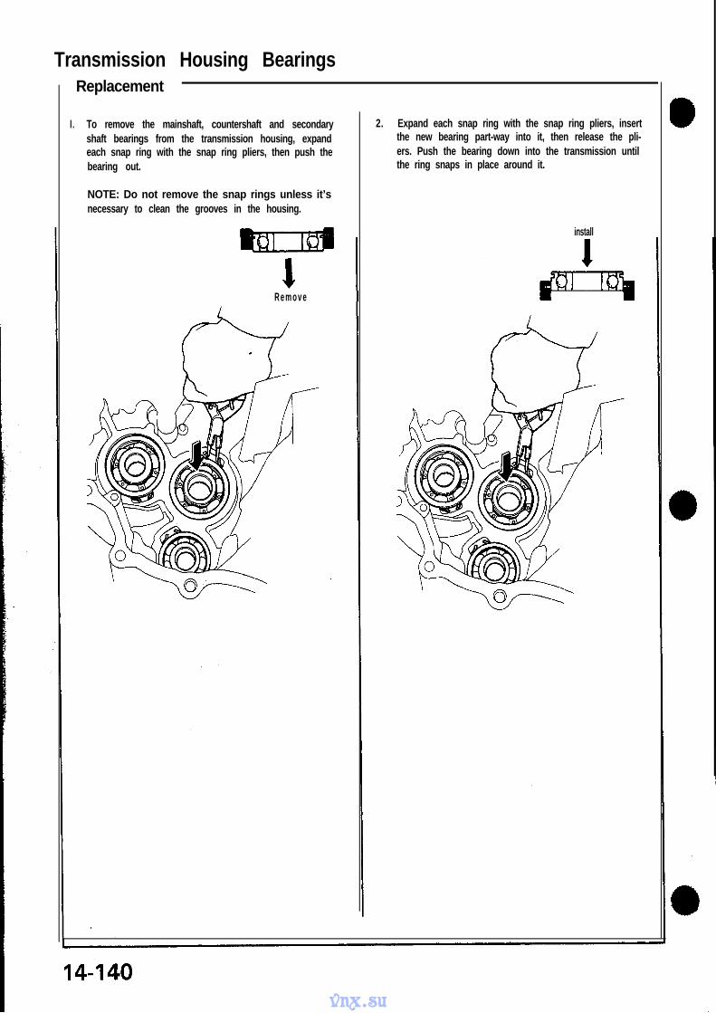
Transmission Housing BearingsReplacement
I . To remove the mainshaft, countershaft and secondary 2. Expand each snap ring with the snap ring pliers, insertshaft bearings from the transmission housing, expand the new bearing part-way into it, then release the pli-each snap ring with the snap ring pliers, then push the ers. Push the bearing down into the transmission untilbearing out. the ring snaps in place around it.
NOTE: Do not remove the snap rings unless it’snecessary to clean the grooves in the housing.
R e m o v e
install
vnx.su
Reverse Idler Gear- Installation
1 . Install the reverse idler gear.
NOTE: install the reverse idler gear so that the largechamfer on the shaft bore faces the torque converterhousing.
CHAMFERFace this side to to raue
2. Set the spring in the reverse idler shaft. Push the springin with the steel ball then install the needle bearing.
NOTE: The steel ball is under spring pressure. Takecare not to let it pop out.
VERSE
SPRIN
STEEL BALL
IDLER SHAFT
NEEDLE ROLLER BEARING
3. Install the reverse idler shaft holder into the transmis-sion housing, then tighten the bolts.
NOTE: Select the appropriate manual valve detentspring when below parts are replaced.l Manual Valve0 Manual Valve Detent Spring0 Manual Valve Lever of Control Shaft
1 . Install the main valve body, including the oil pumpgears, onto the torque converter housing and tight-en to 12 N-m (1.2 kg-m, 9 lb-ft).See page 14-143.
2. Install the control shaft.
3. Install the manual valve detent spring on the mainvalve body and tighten to 14 N-m (1.4 kg-m, 10lb-ft).
4. Set the manual valve to N position.
5 . Measure the distance between the main valve bodyand manual valve as shown.
DISTANCE: 28.0-29.0 mm (1.102-1.142 in)
MAIN VAL)IE BODY MANUAL VALVE
I III II) DISTANCE
MANUAL VALVE
W‘/L/ f\/DETENT SPRING
M A N U A L VAlcE ”LEVER
\N positicn
6. If the measurement is out of tolerance, select theappropriate manual valve detent spring using tablebelow, then install it and recheck.
MANUAL VALVE DETENT SPRING
No. Part Number Length
1 24618-PR9-000 103.5 mm (4.07 in)
24619-PR9-000 104.0 mm (4.09 in) I
3 24620-PR9-000 104.5 mm (4.11 in)
LENGTH
r -I
Parking Brake Stopper- Inspection/Adjustment
1 . Set the parking shift arm in the PARK position.
2. Measure the distance between the face of the park-ing pawl shaft and face of the parking shift arm rollerpin as shown.
DISTANCE: 52.1-53.1 mm (2.051-2.091 in1
DISTANCE
P A R K I N GSHIFT ARM,
PARKING PAWL
PARKING BRAKE STOPPER
3. If the measurement is out of tolerance, select theappropriate parking brake stopper using the table be-low, and install it on the parking shift arm.
PARKING BRAKE STOPPER
vnx.su
Transmission- Reassembly
NOTE: Coat all parts with ATF.
1 . Reassemble the valve bodies in the following numbered sequence.
CAUTION: To prevent stripping the threads, press down on the accumulator cover while installing the bolts.
TORQUE:NOTE: Install the oil pump driven gear
6 x 1 .O mm: all bolts except @: 12 N-m (1.2 kg-m, 9 lb-ft)with its chamfered side facing down.
6 x 1 .O mm: 0,: 14 N-m (1.4 kg-m, 10 lb-ft)
,@ 7 Bolts
NOTE: Install the oil pump driven gear withits chamfered side facing down.
DRIVEN GEARDRIVE GEAR
Ill+
SHAFT
4 DRIVENGEAR
Qill
Chamfered side facesseparator plate.
NOfE: Make sure the pump drive gearrotates smoothly in the normal operatingdirection and the pump shaft movessmoothly in the axial and normal operatingdirect ions.
CAUTION: If the pump gear and pumpshaft do not move freely, loosen the valvebody bolts, realign the shaft, and thenretighten to the specified torque. Failure toalign the pump shaft correctly will result inseized pump gear or pump shaft.
(cont’d)
vnx.su
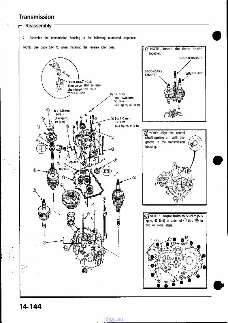
Transmission- Reassembly
2 . Assemble the transmission housing in the following numbered sequence.
NOTE: See page 14-l 41 when installing the reverse idler gear.
LT HOLEe stem so larged ho le faces
bo l t ho le . @ 17 Bolts10x 1.25mm55 N-m(5.5 kg-m, 40 lb-ft)
0 6xl.Omm\ 14N.m
(1.4 kg-m,10 lb-ft)
w u ure J6xl.Omm12 N.m(1.2 kg-m, 9 lb-ft)
@J NOTE: Install the three shaftstogether.
COUNTERSHAFT
SECONDARYSHAFT MAINSHAFT
‘NOTE: Align the controlshaft spring pin with thegroove in the transmissionhousing.
a NOTE: Torque bolts to 55 N.m (5.5kg-m, 40 lb-ft) in order of @ thru @ intwo or more steps.
vnx.su
3. Assemble the transmission in the following numbered sequence.
Replace
(cont’dl
. vnx.su
TransmissionReassembly
4. Set the parking shift arm in the PARK position.
5 . Measure the distance between the face of the parkingpaw1 shaft and face of the parking shift arm rollers pinas shown.
DISTANCE: 52.1 - 53.1 mm (2.051 - 2.091 id
PARKING PAWL SHAFTDISTANCE I
6.
-rI
PARKING BRAKE STOPPER
PAWL
If the measurement is out of tolerance, select the ap-propriate parking brake stopper using the table below,and install it on the parking shift arm.
PARKING BRAKE STOPPER
7 . Install the special tool as shown, and shift to PARKposition.
MAINSHA07924-P
8. Install and torque the new locknuts. Tighten to speci-fied torque, then loosen and retighten to specifiedtorque.
9 . Stake each locknut into its shaft, using a 3.5 mmpunch.
n41 .O mm (0.04 in1
bD I3.5 mm (0.14 id
RSHAFTT
MAINSHAFI
SECONDARYSHAFTLOCKNUT
vnx.su
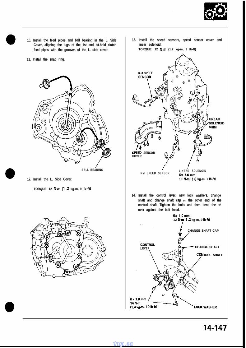
10. Install the feed pipes and ball bearing in the L. SideCover, aligning the lugs of the 1st and Ist-hold clutchfeed pipes with the grooves of the L. side cover.
14. Install the control lever, new lock washers, changeshaft and change shaft cap on the other end of thecontrol shaft. Tighten the bolts and then bend the tabover against the bolt head.
6x l.Omm12 N.m (I .2 kg-m, 9 lb-ftl
CHANGE SHAFT CAP/
CONTROLCONTROLLEVER CHANGE SHAFTCHANGE SHAFT
TROL SHAFTTROL SHAFT
;i!i: ,6- I \LOCK WASHERLOCK WASHER
14-147
vnx.su
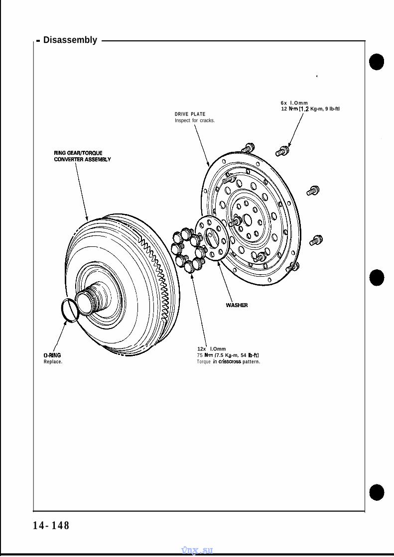
- Disassembly
.
6x l .Omm
DRIVE PLATE12 N-m (I .2 Kg-m, 9 lb-ftl
/Inspect for cracks. /
12x l.Omm75 N*m (7.5 Ka-m. 54 lb-W
Replace. Torque in cris&oss pat tern.
14-148
vnx.su
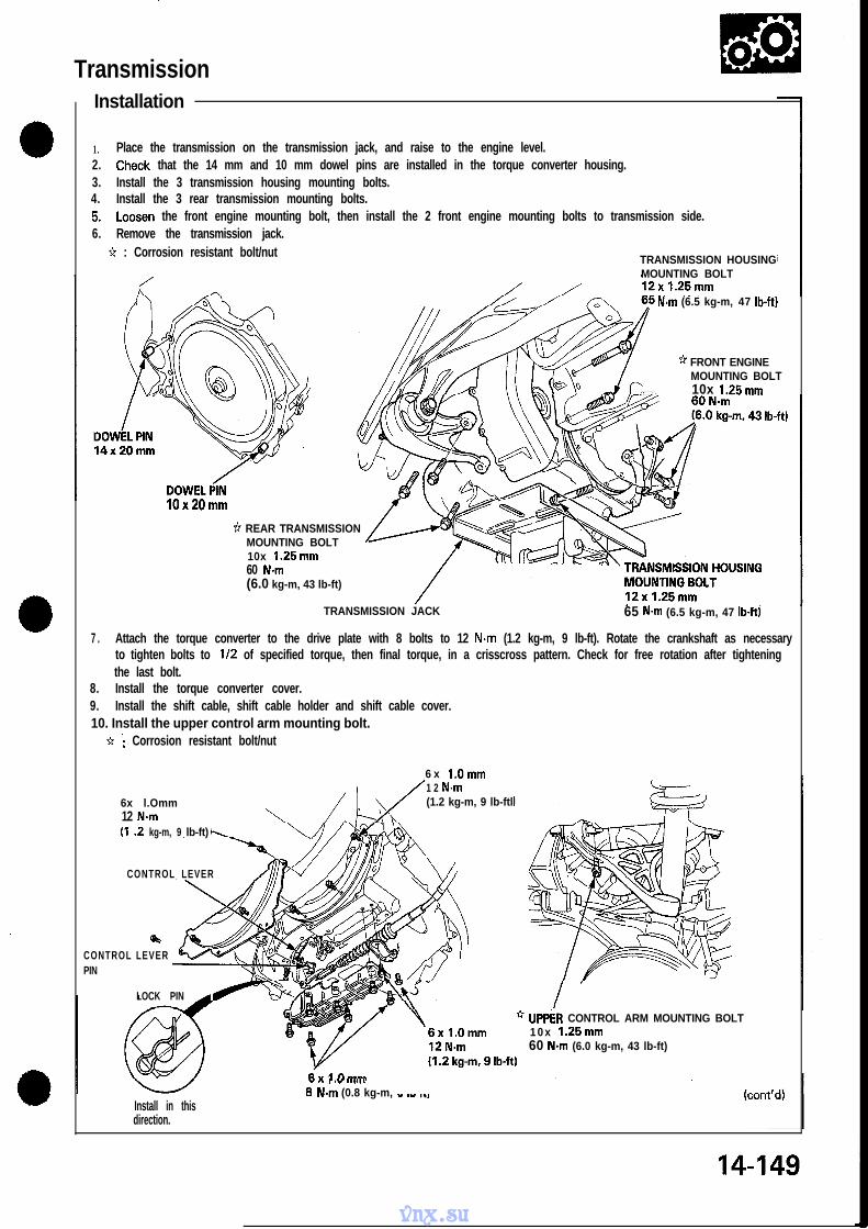
Transmissions Installation
1. Place the transmission on the transmission jack, and raise to the engine level.2. Check that the 14 mm and 10 mm dowel pins are installed in the torque converter housing.3. Install the 3 transmission housing mounting bolts.4. Install the 3 rear transmission mounting bolts.5. Loosen the front engine mounting bolt, then install the 2 front engine mounting bolts to transmission side.6. Remove the transmission jack.
7 . Attach the torque converter to the drive plate with 8 bolts to 12 N-m (1.2 kg-m, 9 lb-ft). Rotate the crankshaft as necessaryto tighten bolts to l/2 of specified torque, then final torque, in a crisscross pattern. Check for free rotation after tighteningthe last bolt.
8. Install the torque converter cover.9. Install the shift cable, shift cable holder and shift cable cover.10. Install the upper control arm mounting bolt.
UPPER CONTROL ARM MOUNTING BOLT1 0 x 1.25mm60 N-m (6.0 kg-m, 43 lb-ft)
Install in thisdirection.
, .” .m,.,,
8 N.m (0.8 kg-m, - .- ..,
14-149
vnx.su
Transmission- Installation (cont’d)
11. Install a new set ring on the end of the left driveshaft and intermediate shaft.12. Install the left driveshaft.13. install the lower control arm to the side beam.
CAUTION: Line up the reference marks on the adjusting bolt, adjusting cam and lower control arm.14. Install the damper fork bolt.15. Install the castle nut to the control arm at the knuckle.
CAUTION: Make sure that the reference marks on the control arm are aligned.16. Install the anti-lock brake system sensor wire clamp and parking brake cable holder.
* : CORROSION RESISTANT BOLT/NUT
DAMPER* SELF-LOCKING NUT
CASTLE NUT FORK BOLTReplace.12x 1.25mm
Ranlaca 85 Nem (p C Is- - f.3 IL U\I
* SELF-LOCKING NUTReplace.
. .vr..-..-.
12x 1.25mm95 N.m (9.5 kg-m, 69 lb-ft) \
D.3 ny-lll, “L I”711
6 x l.Omm/IO N.m 11.0 kgm. 7 lb-ft)
’ CONTROL ARM
SET RING
* SELF-LOCKING NUT ’
’ I
4 ‘ADJUSTING NUT14x 1.5 mm Replace.125 N-m
* ADJUSTING BOLT12x1.25mm
(12.5 kg-m, 90 lb-W 95 N.m (9.5 kg-m, 69 lb-ftl
12 ADJUSTING CAM
17. Install the intermediate shaft and tighten the intermediate shaft mounting bolts to the intermediate shaft support base.18. Install the intermediate shaft heat cover.
SET RING
\/
6xl.Omm10 N.m(I .O kg-m, 7 lb-RI
vnx.su
19. Install the right driveshaft on the intermediate shaft.20. Install the castle nut on the lower arm at the knuckle.21. Install the damper fork bolt.22. Install the castle nut on the control arm at the knuckle.
CAUTION: Make sure that the reference marks on the control arm are aligned.23. Install the ALB sensor wire clamp and parking brake cable holder.
Attachment, 78 x 70 mmClutch Spring Compressor Bolt AssemblyClutch Spring Compressor AttachmentClutch Spring Compressor AttachmentPilot 32 x 60 mmAttachment, 45 x 55 mmDifferential Inspection Tools
*TAPER ROLLER BEARINGReplacement, page 15-5Inspect for operation.
STOPPEG CLIPmm WASHER
vnx.su
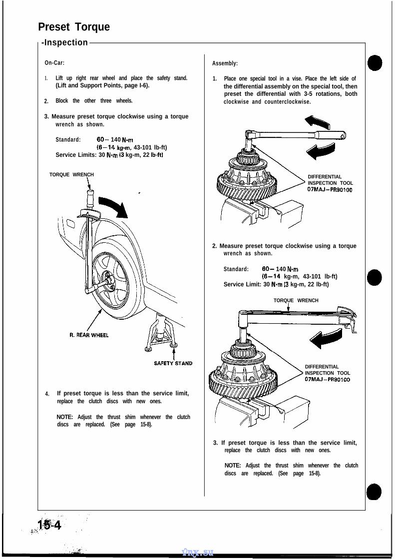
Preset Torque-Inspection
On-Car:
1. Lift up right rear wheel and place the safety stand.(Lift and Support Points, page I-6).
2. Block the other three wheels.
3. Measure preset torque clockwise using a torquewrench as shown.
Standard: 60- 140 N-m(6-14 kg-m. 43-101 lb-ft)
Service Limits: 30 N-m (3 kg-m, 22 lb-ftl
TORQUE WRENCH
SAFETY’STAND
4. If preset torque is less than the service limit,replace the clutch discs with new ones.
NOTE: Adjust the thrust shim whenever the clutchdiscs are replaced. (See page 15-8).
Assembly:
1. Place one special tool in a vise. Place the left side ofthe differential assembly on the special tool, thenpreset the differential with 3-5 rotations, bothclockwise and counterclockwise.
DIFFERENTIALINSPECTION TOOL07MAJ-PR90100
2. Measure preset torque clockwise using a torquewrench as shown.
Standard: 60- 140 N-m(6-14 kg-m, 43-101 lb-ft)
Service Limit: 30 N-m (3 kg-m, 22 lb-ft)
TORQUE WRENCH
DIFFERENTIALINSPECTION TOOL07MAJ-PR90100
3. If preset torque is less than the service limit,replace the clutch discs with new ones.
NOTE: Adjust the thrust shim whenever the clutchdiscs are replaced. (See page 15-8).
vnx.su
Bearing- Replacement
NOTE:0 The bearing and outer race should be replaced as a
set.0 Inspect and adjust the bearing preload whenever the
bearing is replaced.
1. Remove the bearings using standard bearingpullers.
BEARING
PULLER
PULLER
2. Install the bearings using a press as shown.
NOTE: Press the bearings squarely until they bot-tom against the case.
Transmission Housing Side:
+STEEL PLAY R
TAPER ROBEARING
Clutch Housing Side:
+STEEL PLATE
\ r4
ATTACHMENT,45 x 55 mm07MAD-PR90300
vnx.su
DifferentialDisassembly
1 . Hold the differential in a vise using a special tool,then remove the differential housing mountingbolts.
\DIFFERENTIALINSPECTION TOOL07MAJ-PR90100
2. Remove the differential case, then install thespecial tools on the stopper plate as shown.
CLUTCH SPRINGCOMPRESSORATTACHMENT07LAE-PX40100
*STOPPER PLATE
CLUTCH SPRINGCOMPRESSORATTACHMENT07GAE-PG40200
CLUTCH SPRINGCOMPRESSORBOLT ASSEMBLY07HAE-PL50100
3. Compress the spring plate.
4. Remove the stopper clip.
5. Remove the special tools and then remove thestopper plate, spring plate and 60 mm washer.
STOPPER PLATE
/ SPRING PLATE
60 mm WASHER
YDIFFERENTIALHOUSING
15-6
vnx.su
6. Remove the 112 mm thrust shim, clutch discs,clutch plates and 102 mm washer.
CLUTCH PLATES
THRUST SHIM
CLUTCH DISCS
0- 102 mm WASHER
7. Remove the carrier assembly, central gear, clutchplate and clutch disc.
CARRIERASSEMBLY
/ C E N T R A L G E A R
- CLUTCH DISC
8. Remove the ring gear by installing the differentialhousing mounting bolts into the threaded holes andtightening them.
RING GEAR
DIFFERENTIALHOUSINGCOVER
DIFFERENTIALHOUSINGMOUNTINGBOLTS
vnx.su
Clutch Disc, Clutch Plate- Replacement
NOTE: The clutch disks and clutch plates should bereplaced as a set.
1. Remove the clutch discs and clutch plates.(See page 15-6).
2. Soak the clutch discs for five minutes in transmis-sion oil.
3. Install the clutch discs, clutch plates and a stan-dard shim.
112 mm THRUST SHIMOStandard shim
J ) 4 1270-PR8-000 3.0 mm (0.1181 in.)
<Reference>Measure @: 41.7-41.9 mm
(1.6417-1.6496 in)
4. install the differential case.
NOTE: Tighten the bolts evenly in several steps,then torque them in a criss-cross pattern.
Torque: 40 N-m (4.0 kg-m, 29 lb-ft)
5. Make sure the preset torque is within the standard.(See page 15-4).
6. If preset torque is beyond the standard, replace the112 mm thrust shim as necessary.
vnx.su
Differential- Reassembly
1 .
2 .
install the clutch disc, clutch plate, central gear andcarrier assembly.
NOTE: Lubricate the clutch disc surface withtransmission oil.
CARRIER ASSEMBLY
CENTRALGEAR
CLUTCH PLATE
CLUTCH DISC
DIFFERENTIALHOUSINGCOVER
Install the ring gear.
NOTE:“&lign the mark on the differential housingcover v&h the mark on the ring gear.
AMARK
3. Install the 102 mm washer, clutch discs, clutchplate and 112 mm thrust shim.
NOTE:0 Lubricate the clutch discs with transmission oil.0 Position the 112 mm thrust shim with the
thickness size mark facing away from the clutchdiscs.
Thickness Sizemark
112 mm THRUSTSHIM
CLUTCH DiSCS
CLUTCH PLATES
102 mm WASHER
4. Install the 60 mm washer, spring plate and stopperplate.
/ STOPPER PLATE
/7Y(+)g/ S P R I N G P L A T E
_ A 60 mm WASHER
DIFFERENTIALHOUSINGCOVER
(cont’d)
vnx.su
Reassembly (cont’d)
5 . Install the special tools on the stopper plate.
CLUTCH SPRINGCOMPRESSORATTACHMENT07LAE-PX40100
STOPPER PLATE
CLUTCH SPRING‘COMPRESSORATTACHMENT07GAE-PG40200
CLUTCH SPRINGCOMPRES$OR
SEMBLYPL50100
6. Cohpress t&spring plate, then install the stopperc l i p .
7 . Install the differential housing.
NOTE: Align the fingers of the clutch plates andclutch discs.
DIFFERENTIAL HOUSIW
8. Make sure the differential housing touches the finaldriven gear. *
DIFFERENTIAL ,_
\ \
FINAL DRIVEN GEAR
ICLUTCH PLATE
vnx.su
8. Hold the differential in a vise using a special tool,then install the differential housing mount bolts.
NOTE: Tighten the bolts two turns at a time, thentorque them in a crisscross pattern.
8 x 1 .O mm SPECIAL BOLTS407-m (4.0 kg-m, 29 lb-ft)
DIkFERENTIALINSPECTION TOOL07MAJ - Pi+901 00
Oil Sea!- Removal
1 .
2.
3.
Remove the differential assembly.
Remove the oil seal from the transmission housing.
NOTE:l The outer race and bearing should be replaced as a
set.l Inspect and adjust the bearing preload whenever the
bearing is replaced.
1 . Remove the outer race, 90 mm washer and oilguide ring.
,’
2.
DRIVER07746 -0010000 -km ATTACHMENT,
07746 -0010500
lnsfall the oil guide ring and 90 mm washer, thendri\i;e the outer race into the clutch housing.
ATTACHMENT,
07GAD-SD40101
- Adjustment
NOTE: If any of the items listed below are replaced, thebearing preload must be adjusted.0 TRANSMISSIGN HOUSING0 CLUTCH HOUSING0 DIFFERENTIAL0 TAPER ROLLER BEARING and OUTER RACE0 75 mm THRUST SHIM0 90 mm WASHER0 OIL GUIDE RING
1 . Remove the bearing outer race and 75 mm thrustshim from the transmission housing by prying upon the bearing outer race or by heating the housingto about 100°C (212OF).
CAUTION: Do not reuse the thrust shim if theouter race was pried out.
NOTE:l Let the transmission cool to the room tempera-
ture if the outer race was removed by heatingthe case before adjusting the bearing preload.
0 Do not heat the transmission housing in excessof 100°C (212OF).
0 Replace the bearing with a new one wheneverthe outer race is replaced.
0 Repeat on the clutch side.0 There is no shim on the clutch side.
BEARING OUTERRACE
\
76 mm THRUST SHIMReplace.
/
TRANSMISSIONHOUSING
15-12
vnx.su
vnx.su
Oil Seal. Installation
1 . Install the oil seal in the transmission housing.
DRIVER DRIVER ATTACHMENT07749-0010000 -4-l /
07965-SA00600
PILOT 3i x 60 mm07MAD-PR90200
2. Install the oil seal in the clutch housing.
PILOT 32 60 mm07MAD-PR90200
vnx.su
Driveshafts
Special Tools ................................. 16-2
Driveshaft BootCheck the boots on the driveshaft for cracks, damage,leaking grease or loose boot bands.If any damage is found, replace the boot.
Spline LoosenessTurn the driveshaft by hand and make sure the splineand joint are not excessively loose.If damage is found, replace the inboard joint.
Twisted or CrackedMake sure the driveshaft is not twisted or cracked.Replace if necessary.
INBOARDJOINT
I
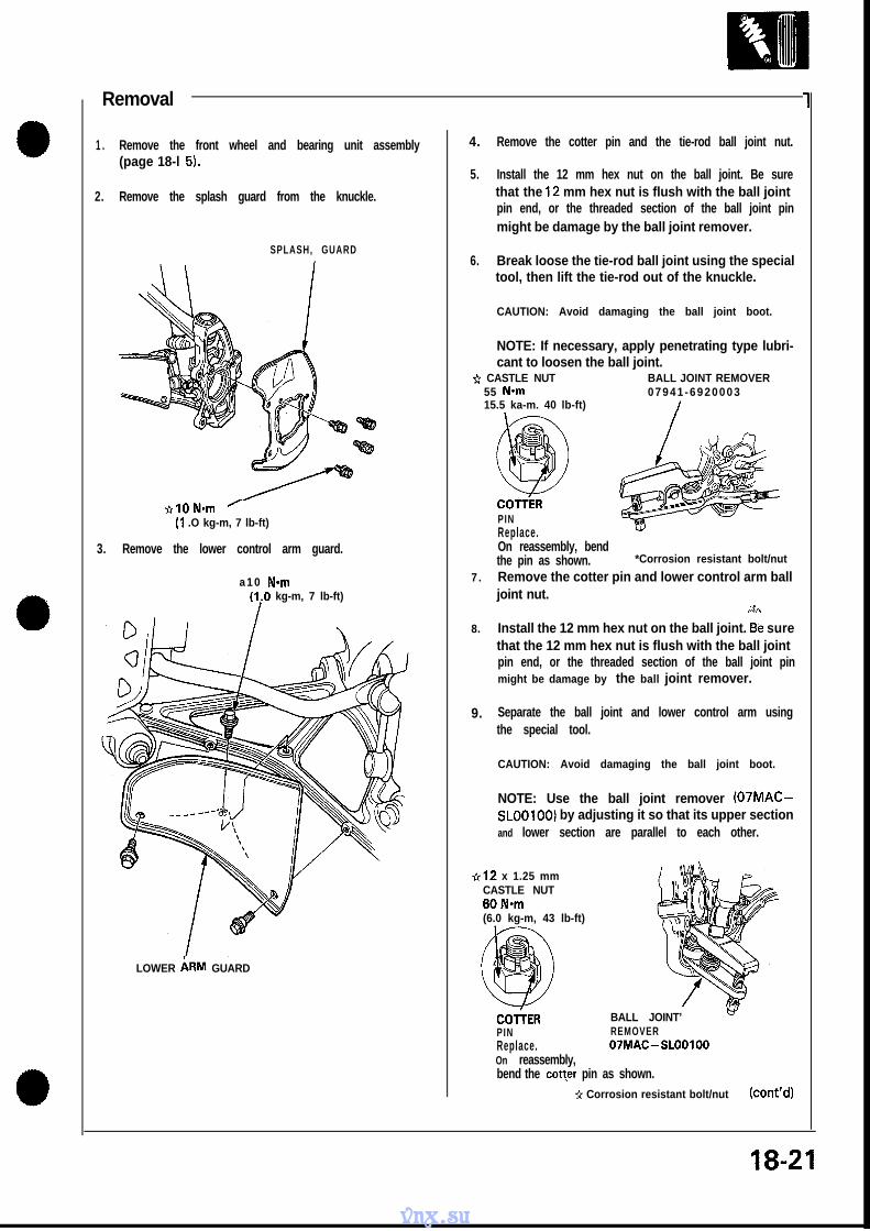
1. Raise the car and place safety stands in the properlocations (see section 1).
2. Remove the rear wheels.
3. Drain the transmission oil (see section 13).
NOTE: It is not necessary to drain the transmissionoil when the right driveshaft is removed.
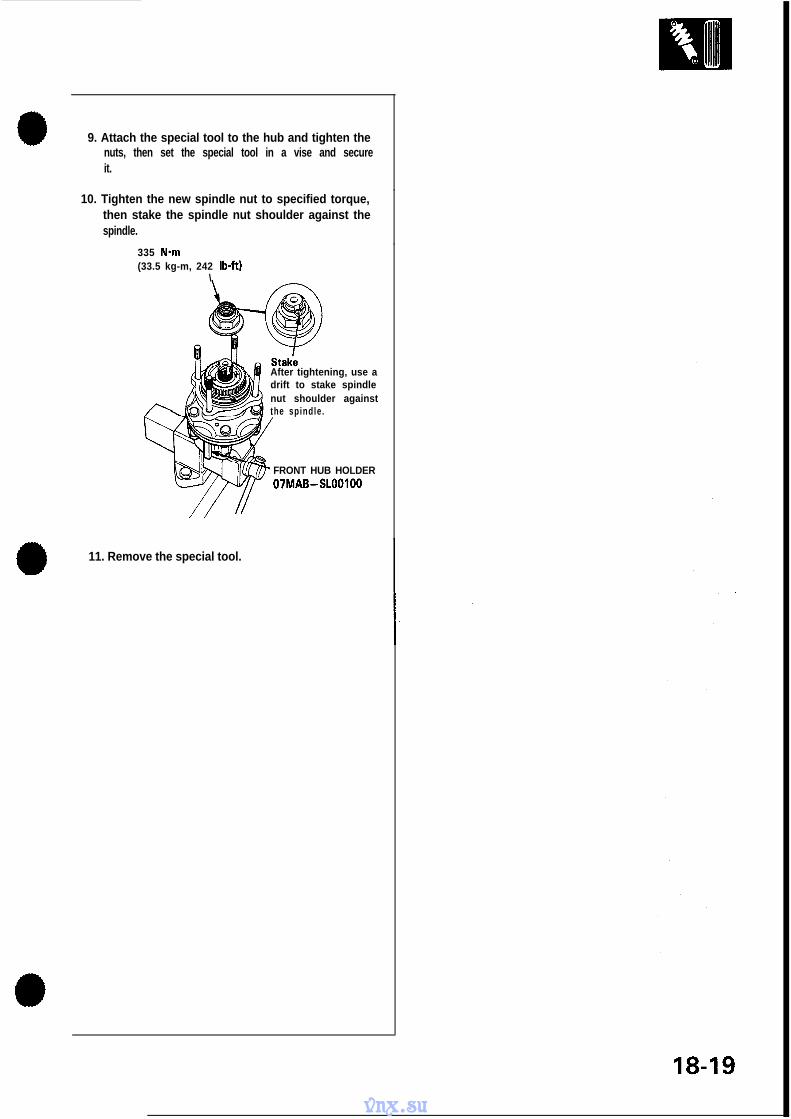
4. Raise the locking tab on the spindle nut and loosenit.
NOTE: Before installing the wheel, clean themating surfaces of the brake disc and inside of thewheel.
26x1.5mmSPINDLE NUTReplace.335 Nom(33.5 kg-m, 242 lb-ft)After tightening, use a driftto stake spindle nut shoulder
WHEEL NUT
ainst the dr iveshaf t .110 N*m
5. Remove the banjo bolt and disconnect the brakehose, then remove the brake hose clamp from theknuckle.
CAUTION: Avoid spilling brake fluid on painted,plastic or rubber surfaces as it can damage thefinish;Wash spilled brake fluid off immediately with cleanwater.
BANJO BOLT35 Nom(3.5 kg-m, 25 lb-ft)
BRAKE HOSE
/
6 mm BOLT10 Nom(I .O kg-m, 7 lb-ft)
.*Corrosion resistant bolt
(cont’d)
16-3
vnx.su
Driveshafts- Removal (cont’d)
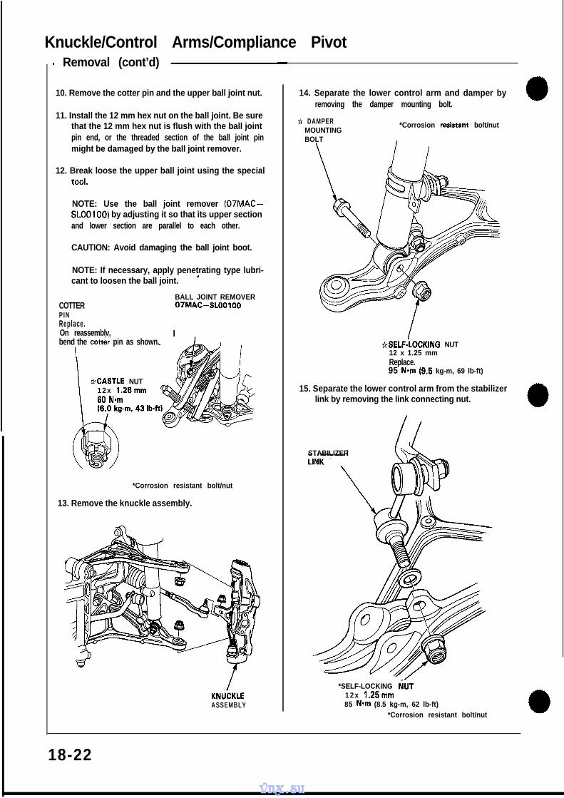
6. Remove the speed sensor from the knuckle and 10. Hold the stabilizer link with a wrench and removerear lower arm, but do not disconnect it. the damper mounting nut.
NOTE: Avoid twisting the wires when reinstallingthe sensors.
a 23 *Corrosion resistant bolt/nut
*I2 x 1.25 mmDAMPER MOUNTINGNUTReplace.95 Nom(9.5 kg-m,67 lb-ft)
7.
8.
9.
*IO hiam(I .O kg-m, 7 lb-ftl
Remove the cotter pin from the toe control armcastle nut and remove the nut.
Install the 10 mm hex nut on the ball joint. Be surethat the 10 mm hex nut is flush with the ball jointpin end, or the threaded section of the ball joint pinmight be damaged by the ball. joint remover.
Position the special tool between the knuckle andcontrol arm as shown, then separate the toe con-trol arm.
CAUTION: Be careful not to damage the ball-jointboot.
COTTER PINReplace.On reassembly,bendI the cotter pin a
a 10 x 1.25 mm CASTLE NUT44 N-m(4.4 kg-m, 32 lb-ftl
/
TOE CONTROL AkM h Corrosion resistant bolt/nut
*Corrosion resistant bolt/nut
11. Remove the stabilizer link from the stabilizer barand knuckle.
REARDAMPER
//
6c N-m(8.5 kg-m, 61 lb-ft)
* 1 2 x 1.25mmSELF-LOCKING NUT
STABILIZER yLINK *Corrosion resistant bolt/nut
1p
e16-4
vnx.su
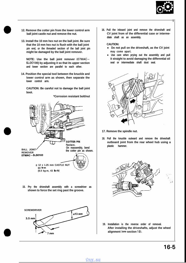
1
12. Remove the cotter pin from the lower control armball joint castle nut and remove the nut.
13. Install the 10 mm hex nut on the ball joint. Be surethat the 10 mm hex nut is flush with the ball jointpin end, or the threaded section of the ball joint pinmight be damaged by the ball joint remover.
NOTE: Use the ball joint remover (07MAC-SLOOI 00) by adjusting it so that its upper sectionand lower section are parallel to each other.
14. Position the special tool between the knuckle andlower control arm as shown, then separate thelower control arm.
CAUTION: Be careful not to damage the ball jointboot.
*Corrosion resistant bolt/nut
BALL JOINT/REMOVER07MAC-SLOOIOO
On reassembly, bendthe cotter pin as shown.
* 12 x 1.25 mm CASTLE NUT60 Nom(6.0 kg-m, 43 lb-ft)
15. Pry the driveshaft assembly with a screwdriver asshown to force the set ring past the groove.
SCREWDRIVER
’ A’7mm
16. Pull the inboard joint and remove the driveshaft andCV joint from of the differential case or interme-diate shaft as an assembly.
CAUTION:l Do not pull on the driveshaft, as the CV joint
may come apart.l Use care when prying out the assembly and pull
it straight to avoid damaging the differential oilseal or intermediate shaft dust seal.
17. Remove the spindle nut.
18. Pull the knuckle outward and remove the driveshaftoutboard joint from the rear wheel hub using aplastic hammer.
19. Installation is the reverse order of removal.After installing the driveshafts, adjust the wheelalignment (see section 18).
16-5
vnx.su
Driveshafts-Disassembly
1 . To remove the boot band, pry up the locking tabswith screwdriver and raise the end of the band.
NOTE: Carefully clamp the driveshaft in a visewith soft jaws.
CAUTION: Take care not to damage the boots.
2. Remove both joints.
0 Outboard joint side only:- Remove the circlip from the outboard joint
groove.- Remove the outboard joint and spring.
Outboard joint only.
3. Remove the rollers from the spider.
ROLLER
/
4. Remove the set ring, then remove the spider with abearing remover.
NOTE: Before disassembly, mark the spider anddriveshaft so they can be reinstalled in their originalpositions.
SET RING BEARING REMOVER
\ /
vnx.su
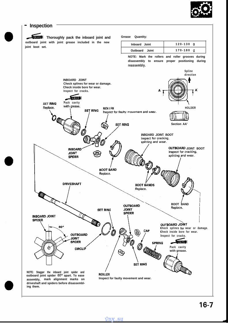
- Inspection
Thoroughly pack the inboard joint andoutboard joint with joint grease included in the new
joint boot set.
INBOARD JOINT
Grease Quantity:
Inboard Joint 1 2 0 - 1 3 0 g
Outboard Joint 1 7 0 - 1 8 0 g
NOTE: Mark the rollers and roller grooves duringdisassembly to ensure proper positioning during
reassembly.
Spl inedirect ion
Check splines for wear or damage.Check inside bore for wear.Inspect for cracks.
SET RING Pack cavity
HOLDER
Section AA’
INBOARD JOINT BOOT
JOINT BOOT
BOOT BAND
Check splines for wear or damage.Check inside bore for wear.Inspect for cracks.
Pack cavitywith grease.
NOTE: Stagger the inboard joint spider andoutboard joint spider 60° apart. To easeassembly, mark alignment marks ondriveshaft and spiders before disassembl-ing them.
Inspect for faulty movement and wear.
16-7
vnx.su
Driveshafts- Reassembly
Outboard joint side
NOTE: Wrap the splines with vinyl tape to preventdamage to the boot.
1. install the outboard boot to the driveshaft, thenremove the vinyl tape.
OUTBOARD BOOTI
2. Install the set ring into the driveshaft groove.
3. Install the spider on the driveshaft by aligning themarks on the spider and end of the driveshaft.
4. install the set ring into the driveshaft groove.
SET RING
al
5. Fit the rollers to the spider with their high shouldersfacing outward.
CAUTION:l Reinstall the rollers in their original positions on
the spider.0 Hold the driveshaft assembly with the rollers up,
to prevent them from falling off.
SPIDER\
ROLLERHigh shoulder facestoward outside.
6. Pack the joint with joint grease included in the newjoint boot set.
Grease Quantity: 170- ‘I 80 g
a-
16-8
vnx.su
0 7. Install the spring and cap, than fit the outboardjoint onto the driveshaft.
OUTBOARD JOINT
Align the roller holders with theinboard joint as shownbelow.
HOLDER
8. Fit the circlip into the outboard joint inner groove.
CIRCLIP
inboard joint side
NOTE: Wrap the splines with vinyl tape to preventdamage to the boot.
9. Install the inboard boot to the driveshaft, thenremove the vinyl tape.
INBOARD BOOTI
IO. Install the set ring into the driveshaft groove.
11. Install the spider on the driveshaft by aligning themarks on the spider and end of the driveshaft.
12. Install the set ring into the driveshaft groove.
SET RING
M a r k
SET RING -
ER
M a r
(cont’d)
16-9
vnx.su
Driveshafts- Reassembly (cont’d)
13. Fit the rollers to the spider with their high shouldersfacing outward.
CAUTION:0 Reinstall the rollers in their original positions on
the spider.0 Hold the drivashaft assembly with the rollers up,
to prevent them from falling off.
SPIDER\ -
ROLLERHigh shoulder facestoward outside.
14. Pack the joint with joint grease included in the newjoint boot set.
Grease Quantity: 120- 130 g
15. Fit the inboard joint onto the driveshaft.
INROARD JOINT
ilign the roller holders with thenboard jo in t as shownkelow.
HOLD‘ER
16. Adjust the length of the driveshafts to the figure
below, then adjust the boots to halfway betweenfull compression and extension.
NOTE: The ends of the boots seat in the groovesof the driveshaft and joint.
L. DriveshaftM/T: 513.5-514.0 mm (20.22-20.24 in)A/T: 519.5-520.0 mm (20.45-20.47 in)
R. DriveshaftM/T/A/T: 542.0-542.5 mm (21.34-21.36 in)
r
16-10
vnx.su
a 17. Install new boot bands on the boots and bend bothsets of locking tabs.
18. Lightly tap on the doubled-over portions to reducetheir height.
NOTE: Install the outboard joint in the knucklebefore installing the driveshaft into the differentialor intermediate shaft. Loosely install the spindlenut this time.
19. Install the new set rings in the driveshaft grooveand intermediate shaft groove.
20. Install the inboard end of the driveshaft into dif-ferential or intermediate shaft.
CAUTION:l Always use a new set ring whenever the drive-
shaft is being installed.0 Make sure the L. driveshaft locks in the differen-
tial side gear groove, and the CV joint subaxlebottoms in the differential.
0 insert the Ft. driveshaft CV joint subaxle into theintermediate shaft until the intermediate shaftset ring locks in the groove in the R. driveshaft.
INBOfiRD JOINTII I
SET RING
L. Driveshaftinboard end
R. Driveshaftinboard end(Intermediate shaft side1
1641
vnx.su
Intermediate Shaft-Replacement
1.
2.
3.
4.
Drain the oil from the transmission (see section13).
Remove the right driveshaft assembly (page 16-3).
Remove the heat shield.
*Corrosion resistant bolt/nut
*6x l.OmmFLANGE BOLT10 N*m(1 .O kg-m, 7 lb-ft)
I
HEAT SHIELD
The bearing support assembly is a light press fit inthe support base. To remove the bearing supportassembly, remove the 8 x 1.25 mm flange bolts,with the support base still attached to the engineblock. Tap the flanged section of the bearing sup-port with a plastic hammer toward the wheel side,then remove the bearing support assembly fromthe support base.
CAUTION: To prevent damage to the differentialoil seal, hold the intermediate shaft horizontal untilit is clear of the differential.
NOTE: Mark the support base and bearing supportduring disassembly to ensure proper positioningduring reassembly.
CAUTION: The bearing support and support baseare made of aluminum. Be careful not to damagethem when servicing.
*Corrosion resistant bolt/nut
SUPPORT BASE
\
Shaftend
\
$76 x 1.25 mmFLANGE BOLT22 N-m(2.2 kg-m, 16 lb-ft)
Mark BEARING S&PORTASSEMBLYLightly tap the support base usinga plastic hammer.
5 . Remove the support base from the engine block.
6 x 1.25 mm FLANGE BOLT22 N-m(2.2 kg-m, 16 lb-ft)
I
SUPPOiT BASE
6. Installation is the reverse order of removal. Alignthe marks and install by tapping on the bearing sup-port assembly shaft end.
vnx.su
- Disassembly
CAUTION: The bearing support and support base aremade of aluminum. Be careful not to damage themwhen servicing.
1. Remove the intermediate shaft outer seal from thebearing support.
2. Remove the external circlip and internal circlip.
LIP
EXTERNAL CklCLIP
3. Press the intermediate shaft out of the shaft bear-ing using the special tool.
Hydraulic press
HUB DWASSEMBLYBASE07GAF-SD40700
/
INTERMEDIATkSHAFT
4. Remove the intermediate shaft inner seal from thebearing support.
INNER SEALReplace.
Icont’d)
16-13
vnx.su
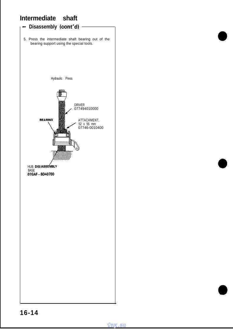
Intermediate shaft- Disassembly (cont’d)
5. Press the intermediate shaft bearing out of thebearing support using the special tools.
Hydraulic Press
DRIVER
J077494010000
ATTACHMENT,52 x 55 mm
. 07746-0010400
HUB DlSlASSEikBLYBASE07GAF-SD40700
16-14
vnx.su
- Index/Inspection
CAUTION:l The bearing support and support base are made of aluminum. Be careful not to damage them when servicing.0 The bearing support and support base are fitted, and must be replaced as an assembly.
*Corrosion resistant bolt/nut
SUPPORT BASECheck for damage. INNER SEAL
Replace.
AEiGii (3--4g)
ARING SUPPORT
EXTERNAL CIRCLIP
Check for damage o
Check for damage or distortion.
*B x 1.25 mmFLANGE BOLT22 Nom(2.2 kg-m, 16 lb-ft)
INTERMEDIATE SHAFT BEARINGReplace.
SET RINGReplace.
16-15
vnx.su
Intermediate shaft- Reassembly
1 . Press the intermediate shaft bearing into the bear-ing support using the special tools.
Hydraulic press
DF!lVER 07749 -0010000
AD-PG40100
HUB DISIASSEMBLYBASE07GAF - SD40700
2. Seat the internal circlip in the groove of the bearingsupport.
CAUTION: Install the circlip with the tapered end
facing out.
INTERNAL CIRCLIP
3. Drive the intermediate shaft inner seal into thebearing support using the special to&.
HUB DIWASSEM
LINNER SEAL
BASE07GAF-SD40700
4. Press the intermediate shaft into the shaft bearingusing the special tools.
.
Hydraulic press
INTERMEDIATE SHAFT
HUB DIRVERATTACHMENT /7
07GAF~SE00200hflflM\
Fit the inner race HUB D&/ASSEMBLY BASEof the bearing. 07GAF - SD40700
-
16-16
vnx.su
5. Seat the external circlip in the groove of the in-termediate shaft.
CAUTION: Install the circlip with the tapered endfacing out.
EXTERNALCIRCLIP
6. Install the outer seal into the bearing support.
Index .....................................EPS Gear Box Installation
and Removal ...........................Illustrated Index .........................EPS Gear Box Inspection ..............Ball Joint Boot Replacement ........
*Power Unit Installationand Removal ...........................
*EPS Control Unit Installationand Removal ...........................
17-3117-3117-32
17-3317-3417-4017-41
17-4217-4317-45
17-4617-47
17-52
17-63
17-6417-68
17-6917-72
17-73
17-74
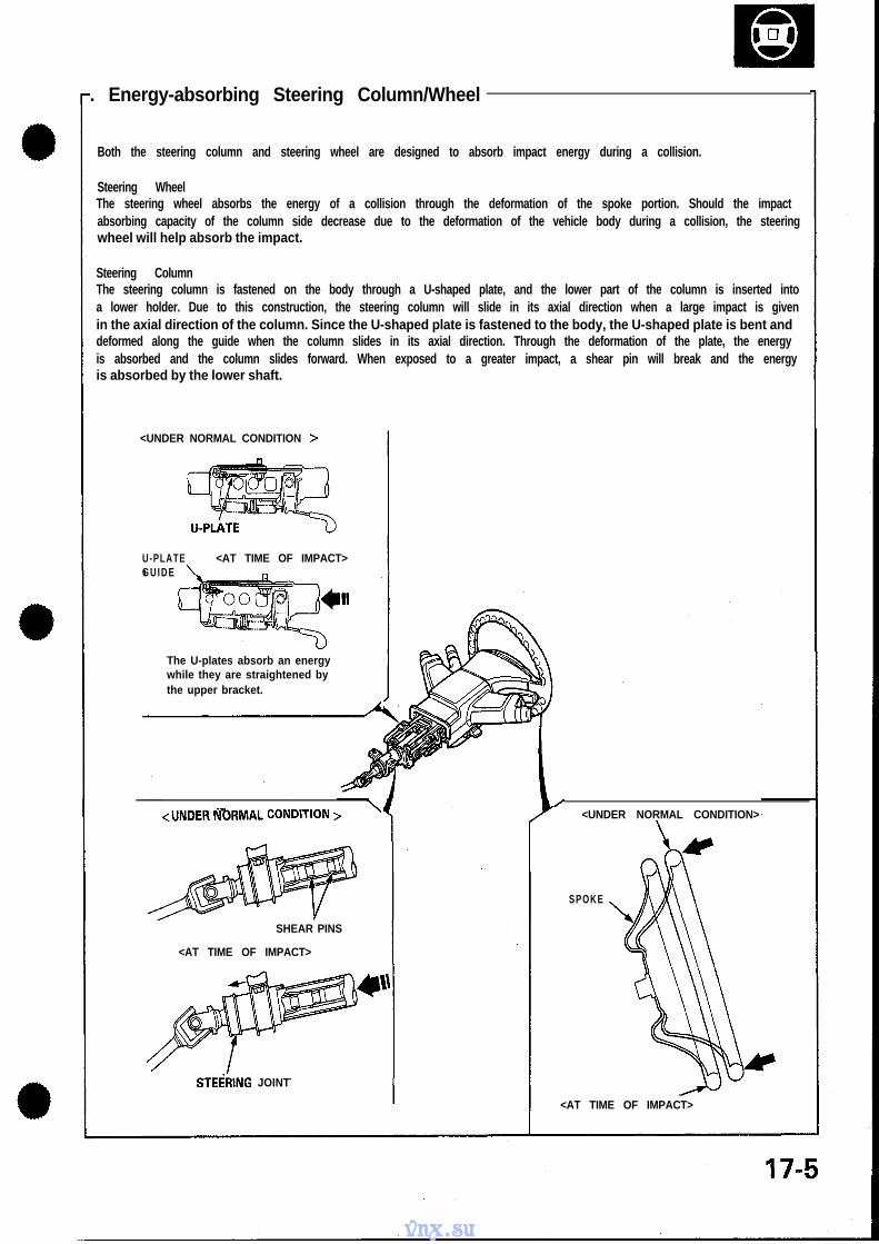
SUPPLEMENTAL RESTRAINT SYSTEM (SRS)The NSX includes a driver’s side Airbag, located in the steering wheel hub, as part of a Supplemental RestraintSystem (SRS). Information necessary to safely service the SRS is included in this Service Manual. Items marked* in each section include, or are located near, SRS components. Servicing, disassembling or replacing these itemswill require special cautions and tools and should therefore be done by an authorized Acura dealer.
l To avoid rendering the SRS inoperative, which can lead to personal injury or death in the event of a severe fron-tal collision, all maintenance must be performed by an authorized Acura dealer.
l Improper maintenance, including incorrect removal and installation of the SRS, can lead to personal injury causedby unintentional activation of the Airbag.
l All SRS selectrical wiring harnesses are covered with yellow outer insulation and related components are locat-ed in the steering column, center console, dash, and dashboard lower panel. Do not use electrical test equip-ment on these circuits.
vnx.su
Special Tools
Ref. No. Tool Number Description
0 07GAFSD40700 Hub Dis/Assembly Base0 07MAA-SLOOI OA 40 mm, Locknut Wrench0 07MAA-SL0020A 43 mm, Locknut Wrench0 07MAA-SL0030A 50 mm, Locknut Wrench
g 07MAASL0040A 07MAG-SLOOI 07MA.Z~SLOOIOO 00 T e s t P i n i o n B a l l J o i n t H a r n e s s S c r e w B o o t W r e n c h A C l i p G u i d e
8 07MAZ-SL00200 Test Harness B0 07MAZ-SL00300 Test Harness C03 07MAZ-SL00400 EPS power unit checker0 07941-6920003 Ball Joint Remover0 07973-6920001 P/S Adjustment Guide0 07974-SD90000 Steering Inspection Arm
The NSX has a tilt/telescopic steering column. The tilt/telescopic mechanism makes it possible to adjust the steering
wheel in fore and aft, and up and down directions.
Tilt MechanismThere is a joint on the upper steering shaft, and the portion of the column between the steering wheel and this jointis adjustable up and down. When the tilt lever is operated, the lock gears are detached from the column gear to releasethe lock. The column moves upward or downward on two pivot bolts. When the tilt lever is returned to a fixed positionafter selecting the steering wheel height, the lock gear is engaged with the column gear to secure the column.
Tl-LT LEVER
PIVOTBOLT
COLUMNGEAR
/
LOCK CEAB
(cont’d)
‘17-3
vnx.su
System Description-Steering Column (cont’d)
Telescopic MechanismThe upper steering shaft is divided into two shafts, connected by splines, making it possible for the shaft to telescopewhile transmitting the rotation of the steering wheel. When the telescopic lever is lowered, the lever pivot turns in adirection to loosen the stopper shim at the tip of the lever pivot, allowing the shaft to make telescope. The telescopicstroke is limited by the slot and stopper on the movable shaft. After selecting a steering wheel position and returningthe telescopic lever to the fastening position, the stopper shim is pressed against the movable shaft the lever pivot tofasten the sliding part.
TELESCOPIC LEVER
17-4
vnx.su
8. Energy-absorbing Steering Column/Wheel
Both the steering column and steering wheel are designed to absorb impact energy during a collision.
Steering WheelThe steering wheel absorbs the energy of a collision through the deformation of the spoke portion. Should the impactabsorbing capacity of the column side decrease due to the deformation of the vehicle body during a collision, the steeringwheel will help absorb the impact.
Steering ColumnThe steering column is fastened on the body through a U-shaped plate, and the lower part of the column is inserted intoa lower holder. Due to this construction, the steering column will slide in its axial direction when a large impact is givenin the axial direction of the column. Since the U-shaped plate is fastened to the body, the U-shaped plate is bent anddeformed along the guide when the column slides in its axial direction. Through the deformation of the plate, the energyis absorbed and the column slides forward. When exposed to a greater impact, a shear pin will break and the energyis absorbed by the lower shaft.
<UNDER NORMAL CONDITION >
U-PLATE <AT TIME OF IMPACT>G U I D E
The U-plates absorb an energywhile they are straightened bythe upper bracket.
A
<UNDER IVORMAL CONDITION > ’
SHEAR PINS
<AT TIME OF IMPACT>
STEgRING JOINT
/<UNDER NORMAL CONDITION>
SPOKE
<AT TIME OF IMPACT>
vnx.su
Inspection- Steering Wheel Rotational Play -
1 . Place the front wheels in a straight ahead positionand measure the distance the steering wheel can beturned without moving the front wheels.
2. If the play exceeds the service limit, check all steer-ing components.Service Limit: 5 cm (0.2 in)
- Steering Effort Check(Manual Steering Only)
1 . Raise the front wheels off the ground (see sec-tion 1).
2. Turn the steering wheel with a spring scale andcheck its reading.
3. If the reading exceeds the service limit, adjustthe steering gearbox as shown on the next page.Service Limit: 20 N (2 kg, 4.4 lb)
-Power Assist Check With Car -Parked (Electrical Power SteeringOnly)
Turn the steering wheel with a spring scale. Readthe measurement when the front wheels or steer-ing wheel start to move.
Operation Standard
I Condition Stationary Swingoperation load I
vnx.su
--Steering Gearbox Adjustment
Manual Steering:
1 . Loosen the rack guide screw locknut.2. Tighten, loosen and retighten the rack guide screw
two times to 5 N-m (0.5 kg-m, 3.6 lb-ft), then backit off 15O.
3. Tighten the locknut on the rack guide screw with thespecial tool.
4. Check for tight or loose steering through the com-plete turning travel.
5. Recheck steering effort.
To calculate the indicated torque value, use the formulaon page 17-26.
m Store a removed airbag assembly with thepad surfce up, if the airbag is improperly stored facedown, accidental deployment could propel the unit withenough force to cause serious injury.
CAUTION:l Before removing the steering wheel, aline the front
wheels straight ahead.l Do not install used SRS parts from another car.
When repairing, use only new SRS parts.l Carefully inspect the airbag assembly before install-
ing. Do not install an airbag assembly that shows signsof being dropped or improperly handled, such as dents,cracks or deformation.
l Always keep the short connector on the airbag con-nector when the harness is disconnected.
l Do not disassemble or tamper with the airbag as-sembly.
1 . Disconnect both the negative cable and positive ca-ble from the battery.
2 . Remove the maintenance lid form the steering wheellower cover, then remove the short connector.
3. Disconnect the connector between the airbag andcable reel.
4. Connect the short connector to the airbag side ofthe connector.
‘CONNECTOR
MAINTENANCE
CABLE REELCONNECTOR
3-P\ SAORT CONNECTO;
(RED)
5 . Remove the two TORX@ bolts using a TORX@ T30bit, then remove the airbag assembly.
CRUISE CONTROL SET/RESUMESWITCH
TORX@ BOLTI
TORX@ BOLTS
AIRBAG ASSEMBLY
(cont’d)
vnx.su
-Removal (cont’d)
7. Disconnect the connectors from the horn and cruisecontrol set/resume switches remove the airbag con-nector from its dips.
CRUISE CONTROLSET/RESUME SWITCHESCONNECTOR
8. Remove the steering wheel nut.
9. Remove the steering wheel by rocking it slightly fromside-to-side as you pull steadily with both hands.
STEERING WHEELNUTReplace. \
-Disassembly/Reassemblym Store a removed airbag assembly with thepad surface up. If the airbag is improperly stored facedown, accidental deployment could propel the unit withenough force to cause serious injury.
NOTE: If an intact airbag assembly has been re-moved from a scrapped car or has been found defec-tive or damaged during transit, storage or service,it should be deployed (See section 23).
CAUTION:l Carefully inspect the airbag assembly before install-
ing. Do not install an airbag assembly that shows signsof being dropped or improperly handled, such as dents,cracks or deformation.
l Always keep the short connector on the airbag con-nector when the harness is disconnected.
l Do not disassemble or tamper with the airbag as-sembly.
CAUTION:l Before installing the steering wheel, align the front
wheels straight ahead.l Be sure to install the harness wires so that they are
not pinched or interfering with other car parts.l Do not replace the original steering wheel with any
other design, since it will make it impossible to proper-ly install the airbag. (only use genuine HONDA replace-ment parts)
0 After reassembly, confirm that the wheels are stillstraight ahead and that steering wheel spoke angleis correct. If minor spoke angle adjustment is neces-sary, do so only by adjustment of the tie rods, not byremoving and repositioning the steering wheel.
m Confirm that the airbag assembly is secure-ly attached to the steering wheel; otherwise, severe per-sonal injury could result during later airbag deployment.
1. Before installing the steering wheel, center the ca-ble reel.Do this by first rotating the cable reel clockwise un-til it stops.Then rotate it counterclockwise (approximately twoturns) until:
- The yellow gear tooth lines up with the mark on thecover.
- The arrow on the cable reel label points straight up.
ARROW MARK
YELLOW GEAR TOOTH
ALIGNMENT MARK
2. Install the steering wheel.NOTE: Be sure the steering wheel shaft engages thecable reel.
50 N.m
3. Insert the cruise control set/resume 4-P connectorand airbag connector to the steering wheel clips.
4. Connect the horn connector.
CRUISE CONTROLSET/RESUME SWITCHESCONNECTOR
HORNCONNECTOR
vnx.su
a 5 . Install the airbag assembly with new TORX@ bolts.
7 . Disconnect the short connector from the airbag con-nector.
a 8. Connect the airbag 3-P connector and cable reel 3-Pconnector.
9. Attach the short connector to the lid, and install thelid on the steering wheel lower cover.
IMAINTENANCE \ t I
LID SHORT CONNECTOR(RED)
10. Connect the battery positive terminal and then con-nect the negative terminal.
1 1. After installing the airbag assembly, confirm propersystem operation:0 Turn the ignition to II: the instrument panel SRS
warning light should come on for about 6 secondsand then go off.
0 Confirm operation of horn buttons.0 Confirm operation of cruise control set/resume
switch.0 Turn the steering wheel counterclockwise and
make sure the yellow gear tooth still lines up withthe alignment mark.
YELLOW GEAR~TOOTH
ALIGNMENT MAR
17-I 1
vnx.su
Steering Column-Removal
1 . Disconnect both the negative cable and positive ca-ble from the battery.
2. Remove the airbag assembly and steering wheelfrom the column (page 17-8).
3. Remove the dashboard lower panel, knee bolsterpad, and knee bolster.
KNEE BOLSTER
DASHiOARD KNEE B’OLSTERLOWER PANEL PAD
4. Remove the column lower face. Disconnect the con-nector between the cable reel and the SRS main har-ness, then remove the connector holder.
NFACE
5 . Remove the column lower cover, and column uppercover.NOTE: Be careful not to damage the column covers.
COLUMN UPPER COVER
if-5
COVER
6. Disconnect the TCS sensor.
TCSCONNECTOR(GREEN)
SRSMAIN -HARNESS(YELLOW)
CABLE REELCONNECTOR( Y E L L O W )
CONjllECTOR HOLDER
TCS SENiOR
vnx.su
7. Remove the combination switch assembly from thecolumn shaft.NOTE: The combination switch can be removed bydisconnecting only the TCS connector.
COMBINATION SWITCH
8. Remove the steering joint cover.
STEERING JOdTCOVER
9. Remove the steering joint bolts and washers fromthe joints.
LOCK WASHERS
STEERlNG”JOlNT BOLTS
10. Disconnect the ignition switch connectors and re-move the column holder, then remove the columnassembly by removing the attaching nuts.
HOLDER FLANGE NUTS
8x1.25 mmBOLT WASHERS
17-13
vnx.su
Steering Column
6 m m
STEERING COASSEMBLY
SOCKET BOLT
RETAWNG Check for damage.
STEERINGBOLTS23 N-m(2.3 kg-m,
8x 1.25 mm NlJi1 6 N-m(1.6 kg-m, 12 lb-ft) Y
8 x 1.25 mmBOLT/WASHERS23 N’m(2.3 kg-m.1 7 lb-ft)
CLIP
Y O K E
17 lb-ft)
v-CLAMPS
JOINT COVER
NOTE:l Check the telescopic mechanism, tilt mechanism, and steering joint bearings or steering shaft for movement and damage.
Replace as an assembly if damaged or faulty.l If either the steering column assembly or TCS sensor is removed, select the appropriate shim and adjust the distance
between the steering shaft and TCS sensor. Refer to Section 19 for shim selection.
Attach a spring scale to the knob of the telescopic lever. If the force measured is not within the specification, loos-Measure the force required to move the lever. en the locknut then the telescopic adjusting bolt until the
Preload: 70-90 N (7 -9 kg, 15-20 Ibs) correct force can be obtained.
TELESbOPIC LEVER
17-14
vnx.su
-Installation
1 . Slip the lower end of the steering joint onto the pin-ion shaft.
2. Reposition the column assembly on the hangerbracket and loosely tighten with 8 mm nuts.
COLUMN ASSEMBLY
16 N*m(1.6 kg-m, 12 lb-ft)
3. Tighten to the steering joint yoke bolts.NOTE:l Be sure that the lower bolt is securely in the
groove in the st,eering gearbox pinion.l Be sure the pinion shaft and the steering column
shaft are aligned; the joint should slip on freely.If not, reposition the steering rack to correct themisalignment.
STEERING JOINTSlip the upper end of the steering joint onto the steeringshaft /line up the bolt hole with the groove around theshaft) and loosely install the upper bolt.
STEERING SHAFT‘Pull down whiletightening bolt.
TOOTHED LOCK
STEERlNG”JOlNT BOLTS23 N*m(2.3 kg-m, 17 lb-ft)
4. Install the column holder and bolts.
COLUN&HOLDER 23 N-m
(2.3 kg-m, 17 lb-ft)
5 . Tighten the 8 mm nuts to the specified torque.
6. Install the steering joint cover with the clamps andclip.
STEERING JblNT COVER
(cont’d)
17-15
vnx.su
Steering Column- Installation (Cont’d)
7. Install the combination switch assembly on thecolumn shaft.
COMBINATION SWITCH
8. Reconnect TCS sensor.
TCS CONNECTOR(GREEN)
Tcs ~ENBOR
9. Install the column upper cover, and column lowercover.NOTE: Be careful not to damage the column covers.
COLUMN/ UPPER COVER
COMUNLOWERCOVER
10. Connect the harness from the cable reel to the SRSmain harness below the pedal bracket, then attachthe connector holder to the column lower face.
11. Install the column lower face.
HOLDER
m
0
vnx.su
13. Connect the foot light harness and light-on warningchime to the driver under cover, then install the dash-board lower panel.
KNEEBOLSTER
DASHbOARD KNEE HOLSTEINLOWER PANEL P A D
014. Install the steering wheel and SRS airbag assembly
NOTE:l Before removing the steering gearbox, align the front
wheels straight ahead.l Disconnect the battery negative terminal and then
disconnect the positive terminal.
1. Remove the steering joint cover.
STEERING JOINT COVER
ch CLAMP
2. Remove the steering joint bolts, and move the jointtoward the column.
TOOTHED LOCK
STEERING- JOINT BOLTS23 N.m(2.3 kg-m, 17 lb-ft)
3. Raise the car and place safety stands in the properlocations (see section I).
4. Remove the front wheels.
5 . Remove the cotter pin from the tie-rod ball joint nutand remove the nut.
6. Install the 12 mm hex nut on the ball joint. Be surethat the 12 mm hex nut is flush with the ball jointpin end, or the threaded section of the ball joint pinmight be damaged by the ball joint remover.
7 . Separate the tie-rod ball joint and knuckle using thespecial tool.
CAUTION: Avoid damaging the ball joint boot.
NOTE: If necessary, apply penetrating type lubricantto loosen the ball joint.
X!Y CASTLE NUT45 N.m(4.5 kg-m, 33 lb-ft)
a Corrosion resistant
COTTERPINReplaceOn reassembly, bendthe cotter pin as shown.
8. Remove the folding spare tire and spare tire holdreplate.
11. Remove the bolts and nuts of the gearbox and crossbeam.
* IOmmNUTS 0 Install the battery.60 N.m 0 Install the spare tire holder plate and folding spare(6.0 kg-m, 43 lb-ft) tire.
* lOx97mmFLANGE BOLT \
* 10x97 mmFLANGE BOLT
*Corrosion resistant bolt/nut
12. Remove the steering gearbox from the cross beamby removing the mounting bolts.
rlr lOx84mm
FRONT CROSS FEAMFLANGE BOLTS60 N.m (6.0 kg-m, 43 lb-f0
FrontGEAf?;OXASSEMBLY
QCorrosion resistant bolt/nut
13. Installation is the reverse order of removal.0 Install the gearbox assembly and spare tire holder
plate frame.
0 Install the steering joint.
14. Connect the battery positive terminal and then con-nect the negative terminal.
15. After confirm proper system operation:0 Turn on the ignition to II: the instrument panel
SRS warnig light should go on for about 6 se-conds and then go off.
l Confirm operation of horn buttons.l Confirm operation of cruise control set/resume
switch.l Turn the steering wheel counterclockwise to
make sure the yellow gear tooth still lines up withthe alignment mark.
YELLOW GEAR TOOTH
17-20
vnx.su
Illustrated Index
CAUTION:l Before disassembling the gearbox, wash it off with solvent and a brush.0 Thoroughly clean all disassembled parts.- .l Replace parts with damaged sliding surfaces.
Q Corrosion resistant bolt/nut
* 10x97 mmFLANGE BOLT
SET SCREW LOCKNUT STEERING
\
GROMMET AChack for damage.
PINION DUST SEAL
/
GEAR HOUSING r-STEERINGGROMMET BCheck for damage.
LOCKNION BEARING NUT
6 0 N-m(6.0 kg-m, 43 lb-ft)
* 10 mm NUT60 N-m(6.0 kg-m, 43 lb-ft)
SCREW
PRESSURE SPRING
PRESSURE PLATE
STEERING RACKInspect surface for damage.
STOP WASHER
COTTER PINQ CASTLE NUT Replace.
IA F kn-m ?? Ih-ftl I
BOOT---.Check for d a m a a e . ’- -
TUBE CLAMP
-
m-
SILICOI” :‘,-.STEERING GREASE Coat thL(Honda P/N 08733-B070E) surface of theCoat the inside of the boot. rack end.
LOCKNUT44N.m / w(4.4 kg-m, TIE-ROD32 lb-it)
17-21
vnx.su
Manual Steering
Carefully clamp the gearbox in a vise with soft jaws.
Remove the boot band.
RODT BANDReplace.
Pull the boots away from the ends of the gearbox,and unbend the tie-rod lock washers.
Hold the rack with a wrench, and unscrew the tie-rods with another wrench.
LOCK WASHER 4 l
Replace. 60 mm (2.34 in1
4. Before disassembly, install the special tool on the pin-ion shaft and check the preload.If the preload is out of the specification, adjust therack guide (page 17-27).If the preload is still out of the specification, disas-semble the gearbox and check each part.
NOTE: Slide the steering rack in the cylinder untilthe end of the projects rack 60 mm (2.34 in.) fromthe cylinder end. Inspection is made near this rackposit ion.
5. Check the pinion preload with a spring scale.Preload 7-17 N (0 .7 -1 .7 kg, 1 .5 -3 .8 lb)
STEERING INSPECTION ARM07974-SD90000
6. Loosen the rack screw locknut, and remove therack guide screw.
RACK G’UIDEI
PRESSURESPRING
RACK SCREWLOCKNUT
vnx.su
7. Remove the set screw locknut using the special tool.
50 mm, LOCKNUT WRENCH07MAA-SL0030A
8. Remove the set screw using the special tool.
l Check the dust seal for damage and remove it ifit must be replaced. Refer to page 17-25 for in-stallation.
SET SCREW DUST SEAL
PINION SCiEW WRENCH07MAA-SL0040A
9. Move the rack toward the gearbox side (i.e. in thedirection of the arrow) as far as it goes, and out thepinion assembly pull when the pinion gear contactsthe cutout in the rack.
NOTE: The rack cannot be removed from the rack-end side.
STEERINGPINION
Arrow direction.
0 Check the bearing movement while pulling thebearing outer race as shown.
NOTE: This type of the bearing has play. The playshould not be excessive.
UPPER- BALLBEARINGOUTER RACE
(cont’d)
17-23
vnx.su
Manual Steering-Overhaul (Cont’d)
0 If the bearing is noisy or has excessive play,replace the bearing using the special tools.
NOTE: Hold the outer race with the tool securely.
DIS/ASSEMBLY BASE
l Press the steering pinion into the new bearing.
NOTE:0 Install the bearing with the wider side of the in-
ner race toward the gear.0 Hold the inner race with the tool securely.
Ezl Bearing mark
BEARING El \!Y’ ‘W
HtiB DIS/ASSEMBLY BASE07GAF-SD40700
10. Remove the steering rack from the cylinder.
STEERIN? RACK
0 Check the gearbox lower bearing and replace itif it is damaged.
Remove the bearing by lightly tapping with a plas-tic hammer as shown. If the bearing is hard to re-move by tapping, heat the gearbox by soaking itin 100°C (212OF) water.
CAUTION: To avoid burns, use heavy gloves whenhandling the heated gearbox. z
LOWER BEARING
Tap with a plastic hammer toremove the bear ing.
17-24
--
vnx.su
0
0
(b,
l Press the new bearing into the gearbox housinguntil it seats using the hydraulic press and spe-cial tool.
NOTE:l Install the bearing with the wider side of the out-
er race toward the bottom of the gearbox.0 Hold the outer race with the tool securely.0 Do not allow dust and other foreign materials to
enter the bearing.
Hydraulic press
P/S ADjUSTMEN+ GUIDE07973-6920001
1 1. lnser the steering rack into the cylinder housing, be-ing careful not to damage the steering rack slidingsurface.
STEERING RACK
12. Install the steering pinion into the gearbox.
NOTE: Do not engage the steering pinion with thesteering rack this time.
TEERING PINION
13. If the dust seal was removed, drive in the new dustseal until it bottoms on the step on the rack screw.
14. Grease the sealing lip of the dust seal.
SET SCREW
\
DUST SEAL
I
Bottom here. Bottom here.
(cont’d)
IT-25
vnx.su
Manual Steering-Overhaul (Cont’d)
15. Wrap the splined area of the steering pinion withvinyl tape and grease the surface of the tape.
16. Slide the set screw over the steering pinion, beingcareful not to damage the sealing lip of the dust seal,then remove the vinyl tape.
17. Tighten the pinion set screw to a torque wrenchreading (indicated) of 5.7 - 7.1 N-m (57 - 7 1 kg-cm,49- 62 in-lb).
NOTE: The above specification is the torque wrenchreading (indicated) when the set screw is tightenedusing a torque wrench 25 cm (10 inches) long. If youtighten the set screw using a torque wrench of thedifferent length, obtain the torque value using thefollowing formulas.
A/(A+B)=YY x Actual torque = XX =Torque wrench reading.
18. Turn the pinion right and left several times to makeset it, then loosen the pinion set screw.
NOTE: Be sure that the pinion gear and rack gearare not engaged.
19. Install the special tool onto the pinion shaft. Attacha spring scale to the tool and pull the scale adjustthe pinion set screw until the gauge reads 1.5- 2.5N (0.15-0.25 kg, 0.33-0.55 lb).
INSPECTION ARM
PINION SCREW/ ;ENCH07MAA-SL004OA
vnx.su
20. Install the pinion set screw locknut, then hold thepinion set screw and tighten the locknut to a torquewrench reading [indicated) of 54 - 69 N-m (5.4 - 6.9kg-m, 39- 50 lb-ft).
NOTE: The above specification is the torque wrenchreading (indicated) when the set screw is tightenedusing a torque wrench 50 cm (20 inches) long. If youtighten the set screw using a torque wrench of thedifferent length, obtain the indicated torque value(torque wrench reading) using the formulas shownin the step 17.Actual: 70-90 N-m (7-9 kg-m, 50-65 lb-ft)indicated: 54-69 N-m (5.4-6.9 kg-m, 39-50
lb-ft)Tool length (B): 15 cm (6 in)
50 mm, LOCKNUT WRENCH PINION SCREW WRENCH
07HAA-SL0030A \ 07MAA-S/L0040A
21. Turn the pinion shaft slowly, then insert the rackand engage the rack and pinion gears.
22. The system is in neutral when the rack end projects60 mm (2.34 in) from the cylinder end.
24. Tighten, loosen and retighten the rack guide screwtwo times to 5 N-m 10.5 kg-m, 3.6 lb-ft), then backit off 15O.
(cont’d)
17-27
vnx.su
Manual Steering-Overhaul (Cont’d)
,25. Install the locknut on the rack guide screw, and tight-en the locknut to a torque wrench reading (indicat-ed) of 52 N.m (5.2 kg-m, 38 lb-ft) while holding therack guide screw with a wrench.
NOTE: The above specification is the torque wrenchreading (indicated) when the locknut is tightened us-ing a torque wrench 50 cm (20 in) long. If you tight-en the locknut using a torque wrench of the differentlength, obtain the indicated torque value (torquewrench reading) using the formulas shown in thestep 17.Actual: 68 N-m (6.8 kg-m, 49 lb-ft)Indicated: 52 N-m (5.2 kg-m, 38 lb-ft)Tool length (8): 150 mm (6 in)
07MAA-SL0020A
26. Screw each rack end into the rack while holdingthe lock washer so its tabs are in the slots in therack end.
NOTE: Install the stopper washer with the cham-fered side facing out.
LOCK WASHER
RACK END
27. Tighten the rack end securely, then bend the lockwasher back against the flat on the flange as shown.
NOTE: Coat the stopperwasher with grease suffi-ciently.
28. Install the boots on the rack end with the tubeclamps.NOTE:l Coat the rack end and inside of the boot with the
grease.l Before installing the boot, be sure that the pres-
sure inside of the boot is the atmosphericpressure.
l Install the boot band with the rack in the straightahead condition (i.e. right and left tie-rods areequal in length).
- STEERING GREASE SILICONE GREASE(Honda P/N 08733-B070E) Coat the slidingCoat the inside of the boot. surface of the rack
0-
*
vnx.su
29. Install the new boot bands on the boot and bend bothsets of locking tabs.
30. Lightly tap on the doubled portions to reduce theirheight.
NOTE: After assembling, slide the rack right and leftto be certain that the boots are not deformed ortwisted.
31. If the tie-rod ends were removed, install the tie-rodson the right and left rack ends and screw them inuntil the threaded section is 11 mm (0.43 in) inlength.
11 mm 10.43 in)
‘Hand tighten.
TIE-ROD’ END
32. Install the gearbox on the cross-beam (page 17-20).
33. Check the wheel alignment and adjust if necessary(Section 18).
vnx.su
Manual Steering-Ball Joint Boot Replacement
1 . Remove the circlip and the’boot:
CAUTION: Do not contaminate the boot installationsection with grease.
2. Pack the interior of the boot and lip with grease.
LIP
BOOT INSTAL”LATION SECTION‘:
3. Wipe the grease off the sliding surface of the ballpin, then pack the lower area with fresh grease.
CAUTION:F Keep grease off the boot installation section and
the tapered section of the ball pin.l Dvnot allow dust, dirt, or other foreign materi-
als to enter the boot.
BALL PIN TAPERED SECTION/
BOoT INSTALLATIONSECTION
4. Install the boot in the groove of the boot installationsection securely, then bleed air.
5 . Insert the special tool into the threads in the ball pinand align the end of the tool with the groove in theboot.Slide the clip over the tool and into position.
BALL JOINTBOOT CLIPGUIDE07MAG-SLOOlOOAdjust the depthby turning the to
CAUTION: After installing the boot, check the ballpin tapered section for grease contamination andwipe it if necessary.
17-30
vnx.su
System Description-Electrical Power Steering (EPS)
OutlineThe NSX uses an electric motor-driven power steering, which possesses the characteristics best suited for a mid engineautomobile. This system is a power-assisted steering device, with a motor inside the steering gearbox driven by the con-trol unit and power unit. Its distinctive features are described below:
l Minimized loss of engine horsepower are decreased, fuel consumption.0 A linear steering feel and the reduction of kick back.0 Since it requires no complicated hydraulic piping, etc., the system is compact and light in weight.
EPS CONTROL UNIT
IPOWER UNIT
\
STEERING WHEEL
IALTERNATOR
AT YPEED SENSOR
BATTEriY /\
/STEERING
Pl-elzml*l~ e.c A mnrrv COLUMN
vnx.su
-I---“’ - ---= �P-=-� n
-Major Components
The Electrical Power Steering system is composed of the following major components:l A steering gearbox that converts rotary operation of the steering wheel into transverse operation via a rack and pinion
mechanism. Steering sensors and an actuating motor are incorporated.l A control unit that computes the optimum amount of power assistance, taking into account steering torque, steering
speed, and vehicle speed. Selfdiagnosis functions are included.l A power unit that drives the motor according to the signals from the control unit. A current sensor is built in to give
feedback information to the control unit. Two relays shut off the power if a problem in the system occurs.l Two speed sensors, the speedometer and the automatic transmission sensor, send vehicle speed information to the
control unit. Two sensors are used as a double-check.
POWER UNIT
FUSE BOX
8-
r
CONiROL UNIT
SPEEDOMETER
w\ AT ‘SPEED SENSSOR
ALTERNATOR
17-32
vnx.su
-System Operation
Manual Steering OperationSteering wheel input rotates the pinion of the gearbox through the universal joint. Due to the rack and pinion mechanism,the rotation of pinion is converted into a transverse motion at the rack, which steers the front wheels throught the tie-rods and knuckles the same as an ordinary rack and pinion system.
Assisting OperationIn addition to the manual steering operation, the steering sensor on the pinion shaft transmits a signal to the controlunit when it receives a steering input. The control unit calculates an adequate motor control with addition of speed sig-nals the two speed sensors, then transmits a control signal to the power unit. Based on the signal from the control unit,the power unit drives the motor inside the gearbox. The torque generated by the motor is transmitted to ball screw throughgears and converted into an assisting thrust in the axial direction of rack. The assisting thrust acts in the steering direc-tion and lessens the steering force required at the steering wheel.
CONTROL UNIT
POWER UNIT I
RECIRCULATINGBALL SCREW
._
STEERING WHEEL
17-33
vnx.su
System Description*Function and Operation
Steering Sensor
The steering sensor consists of a torque sensor, an in-terface, and the rotation sensor.
TORTION BARINPUTSHAFT J
Torque Sensor
The torque sensor converts steering torque input and itsdirection to voltage signals, in conjunction with the in-terface.A torsional force caused by steering operation is convert-ed to an axial movement of a slider core. A variabledifferential transformer is installed around the slider core.Within the tranceformer are three coils, primary coil onthe inside, and two secondary coils, one for right turnsand one for left turns.Alternating current is passed through the primary coilwhen the system is energized. The amount of mutual in-duction from the primary coil to the secondary coilschanges depending on the position of the slider coil.The input shaft and the slider are one piece. Rotation ofthe shaft moves the slider in a circular direction. The pin-ion is turned via the torsion bar. The slider core is installedon the pinion shaft on grooves, and turns with the pin-ion shaft.When there is little resistance, the input shaft tot-don bar,pinion shaft, and the slider core turn together to the sameangle. The slider core does not move up/down.
INTERFACECIRCUIT
TRANSFORME
PINION GEAR
When there is resistance on the input shaft (hard to steer situation), and the slider pin is turned at an angle by the steeringwheel, the tortion bar is twisted due to the resistance. Accordingly, the pinion shaft turns at a smaller angle. The differ-ence in the turning angles changes the position of the slider pin in the groove, forcing the slider core upward or down-ward, depending on the direction of the direction of the turn.
PRIMARY COIL
\
UPPER SECONDARY COIL
/
/SLIDER
LOWER SECONDARY-c
D W GNn. Steering condition Slider movement Induction voltage on secondary coil._-.
A Steering to right Upward shift Voltage on upper coil increases and that on the lower(load steering) decreases
B Advancing straight ahead(no load steering)
Neutral Voltage on upper and lower coils are equal
C Steering to left Downward shift Voltage on lower coil increases and that on the upper(load steering) decreases
17-34
vnx.su
Rotation SensorThe rotation sensor is housed inside the steering gearbox near the pinion. It converts the rotation speed and directionof steering into voltage signals. The rotation of the steering wheel is transmitted to the pinion, which drives the sensorby accelerating its speed through the three pieces of transmission the gears. Acting as a kind of direct current generator,the sensor generates direct current voltage proportionately with the rotational speed of the pinion. When the steeringdirection is reversed, the voltage is generated in the opposite direction. No power is generated when driving straightahead without turning the steering wheel.
Interface CircuitThe interface circuit is housed inside the steering gearbox near the pinion. It rectifies and amplifies the signals from thetorque sensor and the rotation sensor and transmits steering signals to the control unit. A phase compensating circuitis also built in, which changes the output signals in accordance with the drive signals input from the control unit.
lY ROTAdON SENSOR
17-35
vnx.su
System Description
Control UnitThe control unit receives input signals from the car’s speed sensors, torque sensor and steering rotation sensor, andoutputs control signals to the power unit. It performs a multitude of control works including a circuit which diagnosestroubles in each functional part of the system and the control unit itself. The control unit operates the system while theengine is in the process of starting, on receipt of voltage generated by the alternator. The system remains operationalif the engine stalls with the ignition switch in ON position.
< Basic Control >
(I) Travelling speeds are compiled into data, receiving input signals from the car’s speed sensors.(2) The magnitude and direction of torque are compiled into data, receiving input signals from the torque sensor.(3) The rotational speed and direction of steering are compiled into data, receiving input signals from the steering rota-
tion sensor.(4) Determination of motor torque data from the prescribed assisting force map, based on the car speed data, steering
rotational speed data and the steering torque data.(5) Changeover of control modes and output of control signals to the power unit, based on data on car speed, direction
of torque and rotational direction of steering.
Normal Control Mode:The rotational direction of motor is determined afater changing over to the left/right steering mode in accordance withtorque direction data. The mode is switched to the straight ahead mode when the output data is zero.
Return Control Mode:According to torque direction data and steering rotational direction data, the mode is changed over to the return controlmode to improve the steering return characteristic.
Damper Control Mode:According to car speed data, torque value data and steering rotational speed data, the mode is changed over to the dampercontrol mode to improve the convergence property of the steering.
Mode changeoverl Normal model Return model Damper mode
vnx.su
Self-Diagnosis FunctionThe EPS control unit monitors the system inputs and outputs, and the driving current of the motor. If there is a problemin the system, the control unit turns the system off by actuating the relay in the power unit. Power assist stops andnormal manual steering operation resumes. The control unit also turns the EPS indicator light on to alert the driver, andmemorizes the problem in the form of a code. Connecting the terminals of the service check connector with a jumperwire enables the EPS indicator light to blink the problem code when the ignition switch is turned on.
Unloader ControlIf the steering wheel is turned fully and held in the full-lock position, the steering torque reaches the maximum point,and an over-current flows to the motor and the power unit. The control unit detects this and reduces the current flowto the motor.
Average Moving Current ControlThe electric current flow to the motor is estimated from the current values detected by the current sensor, and the aver-age current is obtained at two second intervals. The motor driving current is suppressed when the average current valueexceeds a predetermined marginal value. The control unit regurates the motor current during continuous loading to sup-press any excessive temperature rise in the power unit and the motor.
Over-Voltage ControlIf there is an excessive increase in power source voltage due to a poor ‘battery condition, an alternator voltage regulatorproblem, etc., the motor assisting force increases, resulting in excessive control. To prevent this, the control unit signalsto the power unit are corrected to ensure that adequate assisting force is generated.
17-37
vnx.su
System Description
Power UnitThe power unit consists of a driving circuit, current sensor, field effect transistor (FET) bridge circuit, and two relays.It receives control signals from the CPU and controls the driving current of the motor. The driving circuit controls therotational direction and speed of the motor by driving the FET bridge circuit with a pulse width modulation (PWM) methodon receipt of an input of driving signals from the control unit.
<Rotational Speed Control >The PWM driving signal is a digital signal repeating the process of voltage ON/OFF at a constant frequency, which changesthe ratio of ON time per one cycle of this signal. The ratio is called the duty ratio. When there is a change in duty ratio,the average voltage changes as smoothly as an analog type. The ratio of digital signal voltage (E) and the average voltage(VI is called the duty ratio (6). Its relationship is expressed by V = E x 6. When the duty ratio is low, the rotational speedof motor is slow. As the duty ratio increases, the rotational speed increases to increase the torque.
RELAYCONTROL FROM POWER CURRENTS I G N A L S B ATT E R Y /R E L A Y S E N S O R
<Rotational Direction Control >Normal Mode Control:The table below shows the normal control mode to con-trol the flow of current from the battery:
Steering FET FET FET FETcondition (I) (2) (3) (4)
Motor operation
%h;ing to ON oFF oFF PWM Operates in directionsteerrng to the rrght
Stra ightahead OFF OFF OFF OFF Stops
St3tering to oFF ON PWM oFF Operates in directionsteerrng to the left
(“PWM” in the table indicates PWM control based on
CURRENTFEED BACK I I &IT’ I
GROND‘\
F A I L S A F EFET ISRIVE , . . ..- -_ . .CIRCUIT RELAY
torque sensor data).Return Control Mode:Return control mode improves the steering return charac-teristics. (“PWM” in the table denotes PWM control
Steering condition FET (I) FET (2) FET (3) FET (4)
Return from right steering PWM-r oFFto straight ahead OFF PWM
based on torque sensor data while “PWM-r” PWM con-trol based on rotation sensor).
Return from left steeringto straight ahead OFF PWM-r PWM OFF
Damper Control Mode:The damper mode control which improves the convergence of steering, is performed with damper mode signals fromthe control unit. In this mode, a short current circuit is formed on the motor side by turning off FET (I) and (2), andon FET (3) and (41, which suppresses the returning speed of the steering.<Motor Driving Current Control >A current sensor, power relay and fail-safe relay are built into the power unit. The current sensor detects motor drivingcurrent and transmits data to the control unit. If there is a problem in the system, a cut-off signal is sent from the controlunit to relay, then the relay cuts off motor current to switch to manual steering operation.
17-38
vnx.su
Steering Gearbox<Motor and Power Assist Mechanism >A motor is housed inside the gearbox housing. It consists of a yoke with a permanent magnet fixed in it, a rotor witha field coil, and brushes which pass electricity to rotor commutators. The motor is on the rack shaft of the steering gear-box. The drive current from the power unit flows through the power relay and fail-safe relay to the brushes of the motor.The drive current flows to rotor commutators through brushes, exciting the field coil of the rotor and rotates the rotorwith the magnetic action of the permanent magnet inside the yoke. The rotor rotates in the opposite direction whenthe direction of drive current is reversed.The rotation torque of the motor is transmitted to the ball screw throught the helical gear. The rotation torque on theball screw is converted into assist thrust in the direction of steering rack by the recirculating ball screw. The recirculatingball screw acts to reduce the steering thrust put into the steering rack through the joint to lessen the steering force re-quired at the steering wheel.
<Recirculating Ball Screw >The recirculating ball screw is constructed so that balls roll between the screw shaft and the nut, and those coming outof the screw face enter the screw groove again through a tube for recirculation. The rotation torque on the shaft is con-verted into thrust in axial direction as the slope of the screw shaft presses against the nut throught balls. Since the torqueconversion is made in this method through the screw shaft and balls, the friction is small, high transmission efficiencyis obtained for both the forward and backward directions, and the steering feels identicalto the ordinary manual steering.Furthermore, sicnce the force from the backward direction (force pressing the steering rack) is converted into the rota-tion torque of the screw shaft, instantaneous kick-back from road surface will rapidly rotate the motor. In such a rapidrotation, the inertia of the motor increases, which acts to reduce the kick-back. Any great kick-back will be transmittedfrom the steering rack to the torque sensor on the pinion, which acts to twist the pinion shaft in the same direction asthe input direction of kick-back. As a result, the motor operates the kick-back to reduce assist force.
BALL SCREW NUT
TUBk SiEEL BALL
17-39
vnx.su
Circuit Diagram
YELd A 6 IGI 1 PWR RLYBI PNKlORNa nPoWEA8 II
IBLKlYEL 1
WHTlYEL
I I WH:IRED 1I I [I I I FET 2 83 b-i; ORNdA-I I I-- I I I I
IIII I I I IFET~ *IO&WHT"LI.~ I Llj I
BLKlREDI
F/S RLY B6 b--PNK~. 'II F's
SLDGND2--pzi-
i3+BATTERY ALT.
(L)ERNATOR
SCKECONNECTOR
('PNKlBLU
HEEL SPEED S E N S O R
A l 8 A 1 7 A l 8 A l 5 A l 4 A 1 3 A 1 2 A i l A10 A 9 B12 Bli BID B9 B8 B7 B8
l Always use the test harness to verify the resistance, voltage, current and other electrical characteristics for the EPScontrol unit, torque sensor, steering circuit sensor, power unit, and their connectors.The test probe must not make direct.contact with the connector terminals.
0 Make sure that the terminals are not bent or damaged in any way when a test harness is installed.l A digital circuit tester must be used to perform the inspections.
An analog circuit tester must be used only when this procedure is indicated in the specification figures.l The EPS system connector should not be disconnected except when necessary.l Inspect the connection condition and ground of each EPS system connector before peforming the troubleshooting
procedures.
a
17-42
vnx.su
-Troubleshooting Procedures
Under normal conditions, the EPS indicator light in the gauge assembly comes on when the ignition switch is turnedto the ON position, then goes off after the engine is started. This indicates that the bulb and its circuits are operatingcorrectly.
EPS INDICATOR LIGHT
/
When the EPS control unit senses an abnormality in the system, the control unit memorizes the problem, the EPS indica-tor light blinks at equal intervals, and the power steering assist is turned off.When the EPS indicator light has been reported on, connect the two terminals of the service check connector with ajumper wire. Then turn on the ignition switch and observe the blinking frequency.
SEkVlCE CHECKCONNECTOR (BLU)
IWHT
SERVICE CHECK CONNECTOR (BLU)
17-43
vnx.su
Troubleshooting- Problem Code Display
When the service check connector terminals are connected with a jumper wire, the EPS control unit blinks the EPS indi-cator light to indicate the problem code. The problem codes are indicated by a series of long and short blinks. One longblink equals 10 short blinks. Add the long and short blinks together to determine the problem code, then refer to theTroubleshooting Chart on page 17-51.
Example&G 6.*6 seconds
\ 1 !?I seconds0.36 seconds
The control unit can memorize any number of simultaneous problems. The problem codes are repeated sequentially be-ginning with the lowest number.The problem code is stored in the control unit memory even when the ignition switch is turned off. After repairing theEPS system, disconnect the CLOCK fuse in the relay box for more than 10 seconds to reset the EPS control unit memory.
17-44
vnx.su
e
e
-Test Harness Installation
Test Harness Al Remove the glove box and disconnect the EPS con-
trol unit connector.Connect test harness A.
EPS CONTROL UNIT
/
TEST HAdNESS A07MAZ-SLOOIOO
Test Harness B0 Disconnect the torque sensor and steering speed sen-
sor connectors and connect test harness 6.
TEST HARNESS B07MAi!-SL00200
STEERING ‘GEARBOX
Test Harness C0 Pull the carpet back from the passenger’s side and re-
move the power unit cover.Disconnect the connector and connect test harness C.
POWER UNIT
TEST HARNESS c07MAZSL00300
Power Unit Checker0 Pull the floor carpet back from the passenger’s side
and remove the power unit cover.Disconnect the connector and connect the power unitchecker.
0 Remove the cigarette lighter and connect the powerunit checker.
Connect to thecigarette lighter
POWER UNIT CHECKER07,MA&SLOO400
17-45
vnx.su
v
Flowcharts
Steering is heavy.
Start the engine.
N O Check the t i re pressure and front\ /
1 YES
Refer to the TroubleshootingChart (see page 17-51).
l Power Assist Check with CarParkedConnect a spring scale to thesteering wheel and turn thewheel. Read the measurementwhen the front wheels start tomove.
Operation standard
I Condition Stationary swingoperation load
Without power 12 kg (24.46 lb)assist (engine off) maximum
With power assist 4.2 kg (9.26 lb)(engine running) maximum
1 wheal-alignment,,1
Are they normal?
1 Y E S
Correct the air pressure or wheelalignment.
Park the vehicle on a level surface
1 ahead. ,/wi th the wheels point ing straight
1
Measure the stationary swingoperetion load.Refer to the chart on the left.
Is it within specification?
Y E S
Inspect the mechanical steeingsystem.
EPS system is OK.
17-46
vnx.su
The steering wheel pulls to oneside during driving. I
1
Start the engine.
Is the EPS indicator light on?
1 YES
NO Check the tire pressure, wheelalignment and steering mechani-cal system.
Refer to the TroubleshootingChart (see page 17-51).
The EPS indicator light does notcome on when the ignition switchis turned ON.
Turn the ignition switch ON. I
(To page 17-48)
(cont’d)
17-47
vnx.su
Troubleshooting-Flowcharts (cont’d)
(From page 17-47)
Turn the ignition switch OFF andconnect test harness A.
Turn the ignition switch ON.
Ground the A2 terminal to thebody.
Is the EPS indicator light
N O
Turn the ignition switch OFF.
Remove the gauge assembly andinspect the EPS indicator bulb.
TEST HARNESS A07MAZSLOO 100
Check the continuity between ter-minals 82 and Al 1 and the bodyground.If continuity is present, replacethe EPS control unit. If there is nocontinuity, check the ground ofterminals B2 and A 11.
Replace the indicator light bulb.
Turn the ignition switch ON.
I
Ground the No. 8 (PNK/BLU) ter-minal of the 30-P gauge assemblyconnector to body.
PNKlBLU WIRE,
Is the EPS indicator light on?
Y E S
The circuit in the gauge assemblyis defect ive.
Repair open in the PNKlBLU wire
1 EPS control unit.1between the gauge assembly and
17-48
vnx.su
The EPS indicator light stays on/ after the engin; is started.1
Start the engine.
Is the charging system light off?Check the charging system (seesection 23).
\ /Y E S
Stop the engine.
Short the service check connec-tor and turn the ignition switch
CONNECTOR ISLUI
Is a problem code displayed?
1 NO
Y E S Refer to the TroubleshootingChart (see page 17-51).
Turn the ignition switch OFF.
SERVICE CHECK CONNECTOR (SW
Disconnect EPS control uni t con-nectors A and B.
I
(To pagi 17-50)I I
(cont’d)
vnx.su
TroubleshootingFlowcharts (cont’d)
TEST HARNESS A,---mm- 07MAZ-SLOOIOO
(From page 17-49)
I
Turn the ignition switch OFF and
Start the engine and check thevoltage between the A9 terminaland body ground.
Is there more than 12 V?
IYES
Repair open in the WHTlBLU wirebetween the EPS control unit andthe alternator.
Check the EPS control unit pow-er supply (see page 17-59).If it is O.K. substitute a known-good EPS control unit andrecheck.
vnx.su
-Troubleshooting Chart
The EPS has been reported on:Connect the service check connector with a jumper wire (see page 17-43). Turn on the ignition switch.Read the problem code and perform the troubleshooting according to the troubleshooting chart below.
-r Related corn n e n t s-I-
::itisc5
0
0
0
0-0
0-0
0-
-
I.zzInThlz”
-I-
System indicatedbfv )2P
t-”-0
AZ8Eu2!z-
1 1-1 2
a 1 Torque sensor (VT,, VT2)
0 1 Toraue sensor (VT3)
0 1 Torque sensor WTA)
0 Torque sensor (REF 2.5)
0 Steering wheel speed sensor
0 EPS Dower uni t
0 0
0
-__
1 3
14
2 1-22-3 1-33
3,3LI,423,41
0-0
0
0
17-54 0 0-0
17-56 0 0
-
0--
00-0
0 Power supply (ECU>ignition input)
0 Speed sensor signal . input
17-59
17-60 -
- -
244
17-62 0-
0 EPS control unit
- -
+
17-51
vnx.su
Troubleshooting-Flowcharts
Problem code 11, 12, 13 and 14:l Torque sensor related problems.
Turn the ignition switch OFF.
Connect the EPS test harness A.
Check the voltage between theA7 (+) and A10 (-1 terminals.
Substitute a known-good EPScontrol unit and recheck.
I Y E S
Position the steering wheel so thefront wheels are point ing stra ightahead. Release the streeringwheel and check the voltage be-tween the terminals indicated inthe chart on the right and Al 0 (- )terminal.
Turn the steering wheel to the leftside and gradually apply forcewhen the wheel is turned all theway to the left. At this time,check the voltage between theterminals indicated in the chart onthe right and A10 f-1 terminal.Turn the steering wheel to theright and use the same method tocheck the voltage.
Chart of Standard Output ValuesI ,Test harness Standard Value (V)A terminalNo. (Name)
Stra ight Turned to Turned toahead the left the right
A l 4 (REF 2 . 5 ) 2.52 0 . 1 7 2 . 5 k 0 . 1 7 2.5kO.17
A10 (GND)
+: VT when the wheels are straightNOTE: The indication (* 1 I--(0.25) means that the vol-tage decreases 0.25 V maximum when the steeringwheel is turned compared to the VT1 value when thewheels are positioned straight ahead.
NOTE: The output variationsof VT,, VT2 and VT3 must cor-respond to the manually applied
force.
Are all the voltages within thestandard values?
N O
Substitute a known-good EPScontrol unit and recheck.
(To page 17-53)
vnx.su
(From page 17-52)
Turn the ignition switch OFF.
Disconnect the torque sensor 6-Pconnector from the steering gear-box and connect the test harnessB.
Disconnect the test harness Afrom the EPS control unit only.
T
1Check the cont inuity between theterminals of the test harness A
) the right.and B as indicated in the chart on
,
TEST HARNESS BO?MAZ-SL00200
fypJxpppJxd-lyIO II 1213 1415161718 7 8 9 IO II 12
Terminal Test harness AName terminal No.
Test harness Bterminal No.
12v A 7 3
VT1 A l 6 2VT2 A6 1VT3 Al7 5
REFZ. 5 A l 4 4
GND A10 6
IN O
Is there continuity? -\I
Repair in the wire with no con-tinuity.
1 YESI
Check the continuity on terminalsA6,A7,A10,A14,A16andA17individually to body ground.
Y E SRepair short in the wire with con-tinuity to body ground.
Repair short in RED orBLU wire with continui-ty to body ground.
wire between the power unit and
EPS (50 A) fuse in the main relay
(cont’d)
17-57
vnx.su
Troubleshooting-Flowcharts (cont’d)
(From page 17-57)
I
Connect the power unit checkerto the power unit.
Start the engine.
IFollow the sequence indicated inthe chart on the right to check theoperation of the power unit.
Are the values for all items within(TF
Check the steering wheel speedsensor. bee page 17-54)
Connect to thecigarette l ighter . POWER UNIT CHECKER
07MAZ-SL00400
OUTPUTConnect
CAUTION: Be careful because the steering wheel willrotate if the FET drive switch is turned ON.
Power Unit Checker Operation Sequence
(*): VIS output of sequence 1
NOTE:0 When the steering wheel is turned to the left and right
lock point in sequence 4 and 5, turn on the FET driveswtich.
0 This operation must be completed in a short periodof time under maximum load (within 10 sec.) because
the motor load is large.
vnx.su
Problem code 3 1:0 EPS control unit related problem.
Turn the ignition switch ON.
Do the other indicator lights (ALB,TCS, etc.) come on?
Y E S
Check the No.5 (15 A) fuse andreplace if necessary. ,
Turn the ignition switch OFF. TEST HARNESS A07MAi!-SLOOl OO
Connect test harness A to thewire harness only.
Turn the ignition switch ON.
Check the voltage between theA8 (+ ) and All (- ) terminals ofthe test harness A.
Substitute a known-good EPScontrol unit and recheck.
(cont’d)
17-59
vnx.su
Troubleshooting-Flowcharts (cont’d)
Problem code 33:
0 Speed sensor related problem.
NOTE: Before oerforming the troubleshooting, check the related systems described below.
Is the speedometer operating N O 1 Inspect the speed sensor and speedometer system.normal ly? YES
~ Proceed the troubleshooting procedures described below.Does the A/T warning indicator come LLo n ? YES Perform the A/T troubleshooting (see section 14).
TEST HARNESS ACheck the speed sensor signal (Vo). 07MAZSLOOIOO
I Disconnect the 3-P connectorfrom the speed sensor.
Check for continuity between the/ lVt,.;;~~;;;teqG;alof t h e /
3-P connector and the Al 2 termi- YELlRED
A1~21314~51617~8(9
1011 1(12~13~14~15~16~17~18
View from terminal side
I A
IN O Repair open in the YELlRED wire
Is there continuity? between the EPS control unit and
Y E Sspeed sensor. ,
Check the continuity between theNo. 1 (YELIRED) terminal andbody ground.
SPEED SENSOR
Is there continuity? Repair short in the wire with con-tinuity to body ground.
I(To page 17-61)
17-60
vnx.su
Check the A/T speed sensor signal (V,).
(From page 19-60)
1-1
Disconnect the 22-P connectorfrom the AiT control unit.
Turn the ignition switch ON andcheck the voltage between theNo. 18 (PNK/BLK) terminal of the22-P connector and body ground.
22-P CONNECTOR (To A/T CONTROL UNIT)(Wire harness side)
View fromterminal s ide
b ’ PNKlBLK WIRE
v
I ISubstitute a known-good A/Tcontorol unit and recheck.
NOTE: Do not connect the connec-
tor on the control unit side of test
harness A.
Turn the ignition switch OFF.
TEST HARNESS A07MAZ-SLOOlOo
1
Remove the test harness A fromthe EPS control unit only.
Check for cont inui ty between theA4 terminal of the test harness Aand No. 18 fPNK/BLK) terminal ofthe 22-P connector.
I
rr,101112131415161718 7 8 9101112
‘\I I PNK/BLK WIRE
Repair open in the PNK/BLK wirebetween the EPS control unit andA/T control unit.
YES
Check for cont inui ty between theA4 terminal and body ground.
I
Repair short in the PNKlBLK wire
(cont’d)
vnx.su
TroubleshootingFlowcharts (cont’d)
Problem code 23, 34, 41, 42, 43 and 44:0 EPS control unit related problem.
Check for poor connections or loose wires at the EPS control unit. If there is no abnormality, replace the EPS control unit.
vnx.su
Component LocationIndex
0NOTE:l If an intact airbag assembly has been removed from a scrapped car or has been found defective or damaged during
transit, storage or service, it should be deployed (See section 231.
0 Before removing the gearbox, remove the ignition key to lock the steering shaft.
0 After installing the gearbox, check the wheel alignment and adjust if necessary.
POWER UNITReplacement, page 17-73
CONTROL UNITReplacement, page 17-74
I
S T E E R I N G G E A R B O X STEERING WHEEL/- 1RBAG A S S E M B L Y_- ^ IRemoval/Installation, page 17-64
A lRemoval , page I 1-8Disassembly, 1 ” - mpage I I-Y I
Installation, p: 3ge 17-10
STEERING COLUMNRemoval, page 17-I 2Inspection, page 17-14installation, page 17-15 I
17-63
vnx.su
Power Steering-Gearbox Removal/Installation
NOTE: Before removing the steering gearbox, align thefront wheels ahead straight.
1 . Remove the steering joint cover.
STEERING J.OINT COVER
CL6 CLAMP
2. Remove the steering joint bolts, and move the jointtoward the column.
LOCK
STEERING JOINT BOLTS23N.m(2.3 kg-m, 17 lb-ft)
3. Raise the car and place safety stands in the properlocations (See section I).
4. Remove the front wheels.
5. Remove the cotter pin from the tie-rod ball joint nutand remove the nut.
6. Install the 12 mm hex nut on the ball joint. Be surethat the 12 mm hex nut is flush with the ball jointpin end, or the threaded section of the ball joint pinmight be damaged by the ball joint remover.
7. Separate the tie-rod ball joint and knuckle using thespecial tool.
CAUTION: Avoid damaging the ball joint boot.
NOTE: If necessary, apply penetrating type lubricantto loosen the bail joint.
BALL JOINT REMOVER0794y -6920003 r-l
*CASTLE NUT45N.m (4.5 kg-m,
COTTER PINReplace.On reassembly, bendthe cotter pin as shown.
A Corrosion resistant bolt/nut
8. Remove the folding spare tire and spare tire holderplate.
9. Remove the battery.
10. Remove the spare tire holder
FLOOR UNDERCOVER,
I&=Y!T 8x1.26 mm38-M TYVL I
vVASHERS25N.m(2.5 kg-m, 18 lb-ft)
*Corrosion resistant bolt/nut
17-64
vnx.su
Component Location 0IiiIndex
0NOTE:l If an intact airbag assembly has been removed from a scrapped car or has been found defective or damaged during
transit, storage or service, it should be deployed (See section 23).0 Before removing the gearbox, remove the ignition key to lock the steering shaft.l After installing the gearbox, check the wheel alignment and adjust if necessary.
NOTE: Before removing the steering gearbox, align thefront wheels ahead straight.
1 . Remove the steering joint cover.
STEERING JOINT COVER
2. Remove the steering joint bolts, and move the jointtoward the column.
LOCK
STEERING JOINT BOLTS23N.m(2.3 kg-m, 17 lb-ft)
3. Raise the car and place safety stands in the properlocations (See section I).
4. Remove the front wheels.
5. Remove the cotter pin from the tie-rod ball joint nutand remove the nut.
6. Install the 12 mm hex nut on the ball joint. Be surethat the 12 mm hex nut is flush with the ball jointpin end, or the threaded section of the ball joint pinmight be damaged by the ball joint remover.
7. Separate the tie-rod ball joint and knuckle using thespecial tool.
CAUTION: Avoid damaging the ball joint boot.
NOTE: If necessary, apply penetrating type lubricantto loosen the ball joint.
BALL JOINT REMOVER0794? -6920003 P-7
sr CASTLE NUT45N.m (4.5 kg-m,
COTTER PINReplace.On reassembly, bendthe cotter pin as shown.
*Corrosion resistant bolt/nut
8. Remove the folding spare tire and spare tire holderplate.
9. Remove the battery.
10. Remove the spare tire holder.
FLOOR UNDERCOVER \
30LTNASHERS25N.m:2.5 kg-m, 18 lb-ft)
* Corrosion resistant bolt/nut
17-64
vnx.su
11. Disconnect the connectors from the EPS wireharness.
12. Remove the ground cable by removing the EPS wireharness stay.
E P S W I R EHARNESS STAY
\
EPS WIRE HARNESS
GRdUN6CABLE
a 13. Remove the terminal guard and ground cable.
14. Remove the terminal nuts and the wires from thegearbox terminals.
TERMINAL NUTS
1.0 kg-m, 7 lb-ft
NOTE: After tight-ening the terminalnuts, bend up theterminal tabsagainst the nutssecurely.
\TERMINALGUARD
15. Remove the radiator pipe bracket at the firewall.
RADIATOR PIPE
16. Remove the radiator pipe bracket at the floor, andspace the radiator pipe away from and gearbox.
RADIATOR PIPE
\
(cont’d)
17-65
vnx.su
- Gearbox Removal/Installation (cont’d)
CAUTION: Before removing the gearbox, place a standjack under the gearbox and front cross-beam to lightlysupport them.Lower the gearbox together with the cross-beam.
17 . Remove the bo l t s and nu ts o f t he gearbox andcross-beam.
*10x97 mmFLANGE BOLT
b 10 mm NUTS60 N-m (6.0 kg-m, 43 lb-ft)
(Cross-beam bracket
A
*10x97 m mto Front cross beam)
k
FLANGE BOLT(Cross-beam bracketto front yoss b e a m )
*lO&mNUT V *.I0 mm NUT60N.m *10x97 mm 60N.m(6.0 kg-m, FLANGE BOLTS (6.0 kg-m, 43 lb-ft)43 lb-ft) (Gearbox to
Front cross beam)
LEFT SIDE
*10x84 m mFLANGE BOLT60N.m(6.0 kg-m, 43(Gearbox to FIcross beam)
18. Lower the gearbox and cross-beam with care so as
not to interfere with the radiator pipe.
NOTE: The cross beam is attached to the crossbeam bracket with knock pins.
Remove the cross beam by lightly taping on it with
a plastic hammer, then remove the gearbox.
FRONT CROSS/ BEAMGEhBOXASSEMBLY 0
19. When installing the cross beam to the cross beam
bracket, be sure to align the holes in the cross beamwith the knock pins on the cross beam bracket.
KNOCK PIN
eSr Corrosion resistant bolt/nut
17-66
vnx.su
20. installation is the reverse order of removal.0 Install the gearbox assembly and SST holder plate
frame.l Install the battery.0 Install the SST holder plate and folding spare tire.l Install the steering gearbox joint cover.
Connect the battery positive terminal and then con-nect the negative terminal.
NOTE: After installation, turn the ignition switch ONand check the Electrical Power Steering warning lightfor operation. Check and adjust the wheel alignment(Section 18).
l Turn on the ignition to II: the instrument panelSRS warning light should go on for about 6 se-conds and then go off.
l Confirm operation of horn buttons.l Confirm operation of cruise control set/resume
switch.l Turn the steering wheel counterclockwise and
make sure the yellow gear tooth still lines up withthe alignment mark.
ALIGNMENT MA
17-67
vnx.su
Power Steering4lustrated Index
CkJTION:l Do not try to disassemble the EPS gearbox. If the gearbox is faulty, replace it as an assembly.
ti Corrosion resistant bolt/nut*10x97 mm
FLANGE BOLT
I$1lOxB4mm
FLANGE BOLT
GEARBOX ASSEMBLY
GEARBOX BRACKET
CUSHION B
/“!‘&-m, 43 lb-ft)
610x97 mmFLANGE BOLT60N.m(6.0 kg-m, 43 lb
MOUNT BASE SiEERlNG GROMMETCheck for damage.
*lOmmNU60N.m(6.0 kg-m, 43 lb-ft)
R E HARNESS ST
MOUNT COLLERI.A. ..I-.. . . .a.. #...A
GROUND CABLE .3 lb-ft)/
-ftj
MUUIY I DU3llllUUCheck for damage. &
STOP WASHER BOOT BAND
*CASTLE NUT45N.m(4.5 kg-m, 33 lb-ft)
COTTER PINReplace.
STEERING GREASE/
/(Honda P/N 08733-B070E) /
Coat the inside of the boot. /
x-1 ,/ ,:-ROD
SILICONE GREASE LOCKNUT
Coat the sliding surface 44N.mof the rack end. (4.4 kg-m, 32 lb-ft) T’E-RoD
vnx.su
-Inspection
1 . Carefully clamp the gearbox in a vise with soft jaws.
2. Remove the boot bands.
BbOT BANDReplace.
3. Pull the boots away from the ends of the gearbox,unbend the tie-rod lock washers.
4. Hold the rack with a wrench, and unscrew the tie-rods with another wrench.
LOCK WASHER
l Preload Inspection:
NOTE: Slide the steering rack in the cylinder untilthe end of the rack projects 60 mm (2.34 in.) fromthe cylinder end. Inspection is made near this rackposition.
Install the special tool on the pinion shaft and checkthe preload with a spring scale.If the preload is out of the specification, adjust therack guide.
Preload 30N (3 kg, 6.6 lb1
60 mm (2.34 in.)
STEERING INSPECTION ARM07974-SD90,OOO
l Rack guide screw adjustment:Remove the rack guide screw locknut.
- Tighten, loosen and retighten the rack guide screwtwo times to 4N.m (0.4 kg-m, 2.9 lb-ft), back it off200 +LK
(cont’d)
17-69
vnx.su
Power Steering- Inspection (cont’d)
- Install the locknut on the rack guide screw, and tight-en the locknut while holding the rack guide screw witha wrench.
NOTE: The above specification is the torque wrenchreading (indicated) when the locknut is tightened us-ing a torque wrench 50 cm (20 inches) long. If youtighten the locknut using a torque wrench of a differ-ent length, obtain the indicated torque value (torquewrench reading) using the following formulas.
AI(A+B)=YY x Actual torque =XX = Torque wrench reading.
Tie-rod installation:5 . Screw each rack end into the rack while holding the
lock washer so its tabs are in the slots in the rackend.
NOTE: Install the stopper washer with the cham-fered side facing out.
RAdK END STOPPEti WASHER
6. Tighten the rack end securely, then band the lockwasher back against the flat on the flange as shown.
NOTE: Coat the stopper washer with grease suffi-ciently. \
55N.m(5.5 kg-m, 40 lb-ft)
17-70
vnx.su
7. install the boots on the rack end with the tubeclamps.NOTE:l Coat the rack end and inside of the boot with the
grease.0 Before installing the boot, be sure that the pres-
sure inside of the boot is the atmosphericpressure.
a Install the boot band with the rack in the straightahead condition (i.e. right and left tie-rods areequal in length).
(Honda P/N 08733-B070E)Coat the inside of the boot.
SILICONE GREASECoat the sliding surface
,of the rack end.
8. Install the new boot bands on the boot and bend bothsets of locking tabs.Lightly tap on the doubled portions to reduce theirheight.
NOTE: After assembling, slide the rack right and leftto be certain that the boots are not deformed ortwisted.
LOCKING TABS
BOOT BAND
9. If the tie-rod ends were removed, install the tie-rodson the right and left rack ends and screw them inuntil the threaded section is 11 mm (0.43 in.) inlength.
11 mm (0.43 in.)
Hand tighten.
TIE-ROD END
10. Install the gearbox and the cross-beam (17-66).Check the wheel alignment and adjust if necessary(Section 18).
J
17-71
vnx.su
Power Steering-Ball Joint Boot Replacement
1 . Remove the circlip and the boot.
CAUTION: Do not contaminate the boot installationsection with grease.
2 . Pack the interior of the boot and lip with grease.
BOOT INSTALLATION SECTION
3. Wipe the grease off the sliding surface of the ballpin, then pack the lower area with fresh grease.
CAUTION:l Keep grease off the boot installation section and
the tapered section of the ball pin.l Do not allow dust, dirt, or @her foreign materi-
als to enter the boot.
L PIN TAPEREDTION
BOOT INSTALLATIONSECTION
4. Install the boot in the groove of the boot installationsection securely, then bleed air.
5. Insert the special tool into the threads in the ball pinand align the end of the tool with the groove in theboot.Slide the clip over the tool and into position.
BALL JOINTBOOT CLIPGUIDE07MAG-SLOAdjust the dturning the t
CIRCLIP
CAUTION: After installing the boot, check the ballpin tapered section for grease contamination andwipe it if necessary.
vnx.su
Power Unit
I. Remove the floor mat and speaker cover.
P_. Disconnect the connector from the speaker and re-move the speaker by removing the bolt and nut.
SPEAKER COVER
/
SPEAKER
3.
4.
Replacement
,
Remove the power unit bracket.
Remove the terminal nuts and disconnect the cablesfrom the power unit terminals.
TERMINAL NUTIO N.m(1 .O kg-m, 7 lb-ft) ,
5 . Remove the power unit by disconnecting the con-nector.
10N.m(1 .O kg-m, 7 lb-ft)
10 i .m I(1.0 kg-m POWER7 lb-ft) UNIT
Installation is the reverse order of removal.
NOTE: Turn the ignition switch ON and check theEPS warning light for operation. I
17-73
vnx.su
Control- Unit- Replacement
1 . Remove the dashboard lower panel and glove boxand disconnect the light connector.
GL?VE BOX
DASHBilARDLOWER PANEL
2. Remove the heater duct.
HEATER DUCT
3. Disconnect the connectors from the control unit byremoving the wire harness band.
CONTROL UNIT
4. Remove the power window control unit by pullingit toward you, then remove the control unit.
\ e#
POWER WINDOW CONTROL10LIl(1.0 kg-m, 7 lb-ftl
UNIT
Installation is the reverse order of removal.
NOTE: Turn the ignition switch ON and check theEPS warning light for operation.
m The front and rear dampers contain nitrogen gas and oil under pressure. The pressure must be relievedbefore disposal to prevent explosion and possible injury when scrapping.
Front Suspension: FRONT DAMPERRemoval, page 18-24Disassembly/Inspection, page 18-27Reassembly, page 18-28
OutlineDouble wishbone independent suspension has been selected for each of the four wheels. This eliminates damper frictionalong the steering axis and permits suspension geometry that takes full advantage of the performance potential of thewide, low aspect ratio tires. The double wishbone design also allows the use of aerodynamically-efficient andaesthetically pleasing low fender lines.The knuckles and the suspension arms are manufactured from light-weight, high-strength aluminum alloys. This gives anotable reduction in unsprung weight which results in increased traction and improved ride. It also allows the individualsuspension components to be designed in detail for maximum strength and rigidity.
<FRONT>
STABILIZER
LOWER CONiROL ARM w
<REAR>
UPPERCONTROLA R M ,
LOWER CONTROi ARM --i$&//
To further increase suspension link rigidity and to obtain optimum knuckle geometry, the knuckles and ball joints are con-tained within the wheel profile. At each corner of the car, the individual suspension system is attached to the aluminumstressed skin chassis by a cast aluminum sub-frame. This design further reduces overall weight and ensures that suspen-sion loads are fed into the chassis at the most efficient points and in the most efficient directions.A large front caster angle combined with small trail distance improves straight-line stability and response without caus-ing heavy steering effort.
18-4
vnx.su
(Front Compliance Mechanism)To avoid the usual compromise between ride quality and handling characteristics, a pivot-type “compliance mechanism”has been designed as an integral part of the front suspension. When one of the front wheels is subjected to a rearwardmovement by an uneven. road surface or by heavy braking, the load produced has two separate effects. As with anysuspension system, the load acts in the vertical direction to compress the suspension spring and reduce the ride height.On the NSX the load also acts through both the upper and lower control arms to twist the compliance pivot. This allowsthe wheel to move rearward by a controlled amount, thus absorbing energy. The result is an outstanding ride quality withonly minimal changes to track width and wheel geometry. In Corning, the compliance pivot does not come into play andthe lateral suspension stiffness required for maximum roadholding and optimum control response is maintained.
(Rear Toe Control Arm)Many conventional passenger-car independent rear suspension systems are subject to undesirable changes in toe-inangle with wheel movement. This results in instability both in Corning and in acceleration. In the NSX, the design andpivot locations of the rear toe control arm produce a slight controlled increase in toe-in during bump travel. As a result,the NSX is extremely stable under heavy cornering loads and over bumpy road surfaces.
TOE CONTROL ARM
18-5
vnx.su
Wheel Alignment
NSX four wheel alignment requires the use of equipment designed specifically for four wheel independent suspensionsand capable of immediate feedback.
NOTE: For proper inspection/adjustment of the wheel alignment, check and adjust the following before checkingthe alignment.0 Check that the suspension is not modified.0 Check the tire size and tire pressure.0 Check the runout of the wheels and tires.l Check the suspension ball joints. (Hold a wheel with your hands and move it up and down and right and left to
check for wobbling.)0 Check the height of each suspension (see below).
Standard value
Tire size Tire pressure psi (kpa) Standard height mm (in)[empty car1
Front
Rear
205150 ZRI 5 33 (230) 170-180 mm (6.7-7.1 in)
225/50 ZRI 6 40 (275) 213-223 mm (8.4-8.9 in)
Front:Ground clearance to the center of the lowercontrol arm bolt
Rear:Ground clearance to the center of the toe con-trol arm bolt
Height inspection:0 Before checking for the height, bounce the car up and down several times before measuring.0 Check the height with the car empty, parked on a level surface, with properly inflated tires (tread wear indicators must
not be showing). If the height is out of specification, load or unload the car as necessary.
18-6
vnx.su
‘(I)
e
- Front Wheel Alignment Adjusting Procedure
Adjustment
NOTE: NSX four wheel alignment requires the use of equipment designed specifically for four wheel independentsuspensions and capable of immediate feedback.
The NSX suspension can be adjusted for camber, caster (front only), and toe. However, because each of them relates tothe other, the camber changes when the toe is adjusted for example. Therefore, the total adjustment of the front/rearwheel alignment is required whenever either one of the elements (i.e. camber, caster, or the toe) is adjusted.
<Front wheel alignment adjusting procedure>
Check the ride height.
1Measure camber. 1
111 Adjust cambei
1 Adjust toe. I
&,CASTER
(cont’d)
18-7
vnx.su
w*Wheel Alignment
- Front Wheel Alignment Adjustment Procedure (cont’d)
NOTE:l NSX four wheel alignment requires the use of equip-
ment designed specifically for four wheel indepen-dent suspensions and capable of immediatefeedback.
0 The ride height is very important for setting the align-ment. For every 10 mm of change in the front rideheight, the camber will change approximately IOminutes.
0 The front alignment settings on the NSX areinteractive.A slight change in toe will dramatically change thecamber.
1 . Drive the car on the alignment rack.
2. Check the tire pressure and ride height as describedon page 18-6.
3. Center the steering wheel.
Toe- 1. Measure the lelpgth of the threaded section on
the right and left .r:ck ends.
Standard: 11 mm for shoulderDifference between right and left: 1 mm max.
-2. If the measurement is out of the specification,loosen the locknut and adjust properly.
_ . .
LOCKNUT44 Nom(4.4 kg-m, 32 lb-ft)
Camber- 1. Loosen the locknut on the front lower control
arm adjusting point and adjust the cam posi-tion so that the right and left gaduations onthe adjusting cam are in contact.
-2. Mark the arm in the position which aligns withthe dial center of the adjusting cam.
Loosen the nut
Graduation in contactwith groove wall
125 Nom(12.5 “v-m, 90 lb-ft)
Graduition incontact with,groove wall
vnx.su
c
Casterl Loosen the pivot adjuster mounting nuts under
the compliance pivot and adjust the cam posi-tion so that the right and left gaduations on theadjusting cam are in contact with the groovewalls.
Graduation in contactwith groove wall
GROOVE WALL/
Graduation incontact with
/4. Measure and record the readings for the camberand toe according ‘to the alignment equipmentmanufacture’s instructions.
5 . Adjust the camber and toe at the same time on oneside of the car. Repeat for the other side of the car.
NOTE:0 One graduation on the camber adjusting cam
equals approximately 10 minutes of camberchange.
0 One full turn of the tie rod equals approximately8 mm.
6. Measure the caster according to the alignmentequipment manufacture’s instructions.
7. Adjust the caster.
NOTE: One graduation on the caster adjustingcam equals approximately 10 minutes of casterchange.
8. Measure the readings for camber and toe.
9. Readjust the camber and toe to the specificationsshown.
Front Specifications
T o e -3.5 mm -+ 1.0 mmCamber -0 dagrees 20’ -I 30’Caster +8,degrees 00’ -t 45’
‘.
18-9
vnx.su
Wheel Alignment. Front Turning Angle Inspection -
NOTE:0 Place a car on a level surface before inspection.0 Release the parking brake and be sure that the car is
empty.l Check that the suspensions are at the standard
height (page 18-6).
1 .
2.
Jack up the car and set the turning radius gaugesbeneath the front wheels, and place boards underthe rear wheels the same thickness as one of theturning radius gauges, then lower the car.
NOTE:Be sure that the car is parallel to the ground withthe wheels on the turning radius gauges andboards.
Remove the lock pin on the gauge.Turn the steering wheel fully to the right and leftwhile applying the brake, and measure the turningangle of both wheels.
3. If the measurements are not within the specifica-tions or if the inward turning angles differ betweenthe right and left, check the toe and adjust accor-dingly (page 18-8).
NOTE: Camber0 NSX four wheel alignment requires the use of equip-
ment designed specifically for four wheel indepen-dent suspensions and capable of immediatefeedback.
- 1. Loosen the locknut on the rear lower controlarm adjusting point and adjust the cam posi-tion so that the right and left graduations onthe adjusting cam are in contact.
1 . Drive the car on the alignment rack.
2. Check the tire pressure and ride height as describedon page 18-6.
3. Center the steering wheel.
T o e- 1. Measure the length of the threaded section on
the right and left toe control arms.
Standard: 40 mmDifference between right and left: 1 mm max.
-2. If the measurement is out of the specification,loosen the locknut and adjust properly.
Loosen the nuts40 Nom(4.0 kg-m, 29 lb-ft)
-2. Mark the arm in the position which aligns withthe dial center of the adjusting cam.
Graduation in contactwith groove wall
\ GROOVE WALL
Loosen the nut125 N-m(12.5 kg-m, 90 lb-ftl
/
DIAL CENiER \Graduation incontact withgroove wall
4. Measure the readings for camber and toe accordingto the alignment equipment manufacture’sinstructions.
5. Adjust the camber and toe at the same time on oneside of the car. Repeat for the other side of the car.
Rear Specifications
T o e +6.0 mm + 1.0 mmCamber -1 degrees 30’ k 30’
-
vnx.su
Runout
Jack up the car and raise the wheels off the ground(Section I 1.Place the dial gauge on each front and rear wheel rim,turn the wheel slowly by hand, and check the front/rearwheel runout.
Front and Rear Wheel Axial Runout
Standard:O-O.7 mm (O-0.028 in1
Front and Rear Wheel Radial Runout
Standard: O-O.7 mm (O-0.028 in)
Turn the wheel slowly by hand and check for excessiveaxial and radial runout.
Bearing End Play
Front Wheel End PlayStandard: 0 mm (0 in)Service limit: 0.05 mm (0.002 in) max. Replace.
Rear Wheel End PlayStandard: 0 mm (0 in)Service limit: 0.05 mm (0.002 in) max. Replace.
w-13
vnx.su
Front SuspensionTorque Specifications
CAUTION:
0 Replace the self-locking nuts after removal.0 Replace the self-locking bolts if you can easily thread a non-self-locking nut past their nylon locking insertsfIt should
require 1 N-m (0.1 kg-m, 0.7 lb-ft) of torque to turn the test nut on the bolt).
0 The vehicle should be on the ground before any bolts or nuts connected to rubber mounts or bushings are tightened.
NOTE: Wipe off the grease before tightening the nut at the ball joint.
‘ S
Sr Cord& resistant bolt/nut.
_// *SELF-LOCKING NUTh lOx1.25mm
44 N-m (4.4 kg-m, 32 lb-ft)Replace.
*FLANGE BOLT10 x 1.25 mm60 Nom (6.0 kg-m, 43 lb-ft)
ft CASTLE NUT1 2 x 1.25 mm60 Nom (6.0 kg-m, 43 lb-ft)
Attach the special tool to the hub and tighten thenuts, then set the special tool in a vise and secureit.
Pry the spindle nut stake away from the spindle,then remove the spindle nut.
SPINDLE NUT26 x 1.5 mm Un,stake
FRONT HUB HOLDER/ / “ .07MAB-SLOOlOO
Remove the special tool.
Remove the pulser using a commercially availablebearing puller.
ER
(cont’d)
18-17I
vnx.su
Front SuspensionHub Replacement (cont’d)
5. Separate the wheel bearing from the hub using thespecial tools and a hydraulic press.
CAUTION:0 Hold onto the hub to keep it from failing when
pressed clear.
Hydaulic pressHUB DlSl W H E E L
ASSEMBLY BASE BEARING
07GAF-SD40700
6. Remove the outboard bearing inner race from thehub using the a commercially available bearingpuller.
CAUTION: To prevent damage to the tool makesure the threads are fully engaged before pressing.
NOTE: Wash the bearing and hub thoroughly inhigh flash point solvent before reassembly.
NOTE: Replace the bearing with a new one afterremoval.
7. Press a new wheel bearing into the hub using thespecial tools shown and a hydraulic press.
HUB ASSEMBLYDRIVER ATTACHMENT07GAF-SD4t200 4
Hydraulic press
HUB DlSlkSEMBLY BASE07695-SD90100
8. Install the pulser.
NOTE: Be sure the pulser engages with the pin onthe spindle.
PULSER
PIN
vnx.su
0 9. Attach the special tool to the hub and tighten thenuts, then set the special tool in a vise and secureit.
10. Tighten the new spindle nut to specified torque,then stake the spindle nut shoulder against thespindle.
335 N-m(33.5 kg-m, 242 lb-ft)
\
After tightening, use adrift to stake spindlenut shoulder againstthe spindle.
FRONT HUB HOLDER07MAB-SLOOIOO
*11. Remove the special tool.
vnx.su
Knuckle/Control Arms/Compliance PivotIllustrated Index
Overall Suspension
NOTE:
NOTE: Align the white line on the stabilizer bar with the
bushing end and install the stabilizer bar.
0 Wipe off the grease before tightening the nut at the ball joint.0 Torque specifications, see page 18-14.
I% Corrosion resistant bolt/nut
STABILIZER BARCheck for damage.
*UPPER CONTROL BALL JOINTInspect for faultymovement and wear.
STABILIZER LINKInspect for faultymovement and wear.
-s===== I
COMPLIANCE PIVOT
‘4.. A
=I-LANLit LIULIBx1.25mm23 Nom (2.3 kg-m, 17 lb-ft)
ASSEMBLY
UPPER CONTROL ARMCheck for damageor cracks.
T >_. II y,//LyI /Check for damage or cracks.Check for deterioration or damage.
\
i ’; II ’,j I
\ *UPPER ARM BALLJOINTInspect for faultymovement andw e a r ./
COMPLIANCE PIVOTLOWER BRACKETCheck for damage orcracks.
\
FRONT KNUCKLECheck for damage
ILOWER CONTROL ARMCheck for damage or cracks
\LOWER
*LOWER CONTLOL ARM BALL JOINTInspect for faultymovement and wear.
BALL JOINTinspect for faultymovement and wear.
NOTE: Replace the joint boot if any are damaged. The parts marked with an asterisk (*) have a retainer attaching
the ball joints. Replace the retainer whenever the boot is replaced.
CAUTION: Do not remove the arms, knuckle, and compliance pivot by striking them with a hammer, and take carenot to drop them.
18-20
vnx.su
Removal 1
1 . Remove the front wheel and bearing unit assembly(page 18-l 5).
2. Remove the splash guard from the knuckle.
SPLASH, GUARD
*ION-m ’(1 .O kg-m, 7 lb-ft)
3. Remove the lower control arm guard.
a 1 0 Nom(I,.0 kg-m, 7 lb-ft)
LOWER 6RM GUARD
4. Remove the cotter pin and the tie-rod ball joint nut.
5. Install the 12 mm hex nut on the ball joint. Be surethat the 12 mm hex nut is flush with the ball jointpin end, or the threaded section of the ball joint pinmight be damage by the ball joint remover.
6. Break loose the tie-rod ball joint using the specialtool, then lift the tie-rod out of the knuckle.
CAUTION: Avoid damaging the ball joint boot.
NOTE: If necessary, apply penetrating type lubri-cant to loosen the ball joint.
Replace.On reassembly, bendthe pin as shown. *Corrosion resistant bolt/nut
Remove the cotter pin and lower control arm balljoint nut.
Install the 12 mm hex nut on the ball joint. Be surethat the 12 mm hex nut is flush with the ball jointpin end, or the threaded section of the ball joint pinmight be damage by the ball joint remover.
Separate the ball joint and lower control arm usingthe special tool.
CAUTION: Avoid damaging the ball joint boot.
NOTE: Use the ball joint remover (07MAC-SLOOIOO) by adjusting it so that its upper sectionand lower section are parallel to each other.
412 x 1.25 mmCASTLE NUT00 N-m(6.0 kg-m, 43 lb-ft)
COTiER BALL JOINT’ w
PIN REMOVERReplace. 07MAC-SLOOIOOOn reassembly,bend the cot$?r pin as shown.
10. Remove the cotter pin and the upper ball joint nut.
11. Install the 12 mm hex nut on the ball joint. Be surethat the 12 mm hex nut is flush with the ball jointpin end, or the threaded section of the ball joint pinmight be damaged by the ball joint remover.
12. Break loose the upper ball joint using the specialtool.
NOTE: Use the ball joint remover f07MAC-SLOOIOO) by adjusting it so that its upper sectionand lower section are parallel to each other.
CAUTION: Avoid damaging the ball joint boot.
NOTE: If necessary, apply penetrating type lubri-cant to loosen the ball joint. d
COTTERPINReplace.On reassemblv,
BALL JOINT REMOVER07MAC-SLOOlOO
Ibend the cot& pin as shown.
I
I *CASTLE NUT1 2 x 1.25mm60 Nom
*Corrosion resistant bolt/nut
13. Remove the knuckle assembly.
KNU*CKLEASSEMBLY
14. Separate the lower control arm and damper byremoving the damper mounting bolt.
Q DAMPERMOUNTINGBOLT
*Corrosion reslstsnt bolt/nut
I
*SELF-‘LOCKING NUT12 x 1.25 mmReplace.95 Nom (9.5 kg-m, 69 lb-ft)
15. Separate the lower control arm from the stabilizerlink by removing the link connecting nut.
STABILIZER
*SELF-LOCKING NUT1 2 x 1.25mm85 Nom (8.5 kg-m, 62 lb-ft)
*Corrosion resistant bolt/nut
18-22
vnx.su
-
I Ball Joint Boot Replacement 1
CAUTION: The upper control arm ball joint, lower con-trol arm ball joint and knuckle upper ball joint are attach-ed with the boot retainer to improve the sealing efficacyof the boot.
1 . Remove the circlip and boot.
2. Remove the retainer.
NOTE: The knuckle lower ball joint dose not have aretainer.
COMMERCIALLYAVAILABLE \
Do not damage to the
BEARING PULLER\
CIRCLIP\~
Replaceas a set.
sliding surface of theball pin with the bear-ing puller.
3. Pack the interior of the boot and lip with grease.
LIP
BOOT INgTALLATlON SECTION
BOOT INSTALLATION SECTION
CAUTION: Do not contaminate the boot installa-tion section with grease.
4. Wipe the grease off the sliding surface of the ballpin and pack with fresh grease.
5. Insert the new retainer lightly into the ball joint pin.
NOTE: When installing the ball joint, press the re-tainer into the ball joint pin.
BALL PIN TAPERED SECTION/
BOOT INSSECTION
TALRETAINER
CAUTION:l Keep grease off the boot installation section and
the tapered section of the ball pin.l Do not allow dust, dirt, or other foreign
materials to enter the boot.
6. Install the boot in the groove of the boot installationsection securely, then bleed air.
7. Adjust the special’tool with the adjusting bolf untilthe end of the tool aligns with the groove on theboot.
8. Slide the clip over the tool and into position.BALL JOINTBOOT CLIP
ADJUSTING BOLT BALL JOINTAdjust the depth BOOT CLIP
turning the bolt. GUIDE07MAG-SL00200Adjust the depth
l knuckle lower ball jointonly.
CAUTION: After installing the boot, check the ballpin tapered section and threads for grease con-tamination and wipe them if necessary.
18-25
vnx.su
Damper FrontDamper Removal
1 . Remove the front wheel.
2. Remove the brake hose clamps form the damger.
3. Separate the damper and lower arm by removingthe damper mounting bolt.
*DAMPER MOUNTING
NUT
b Corrosion resistant bolt/nut
12x 1.25mmReplace.
4. Remove the caps from the top of the cowl thenremove the self-locking nuts.
5. Remove the damper assembly.
Q Corrosion resistant bolt/nut*SELF-LOCKING NUT
10x 1.25mmReplace.
. Damper Disassembly/Inspection -
Disassembly:1 . Compress the damper spring with the spring com-
pressor according to the manufacturer’s instruc-tions, then remove the self-locking nut.
CAUTION: Do not compress the spring more thannecessary to remove the nut.
\
LOCKING NUT10 x 1.25 mmReplace.
COMMERCIALLYAVAILABLE
2. Remove the spring compressor then disassemblethe damper as shown on the next page.
Inspection:1.
2.
3.
4.
Reassemble all parts, except the spring.
Push on the damper assembly as shown.
Check for smooth operation through a full stroke,both compression and extension.
NOTE: The damper should move smoothly. If itdoes not (no compression or no extension), thengas is leaking, and the damper should be replaced.
NEEDSNORMAL REPLACEMENT
0 x
1
t
:
:
c
Woodblock
Check for oil leaks, abnormal noises or binding dur-ing these tests.
NOTE: Disposal is see page 18-43.
18-26
vnx.su
Inspecton
SELF-LOCKING NUT10 x 1.25 mm30 Nom (3.0 kg-m, 22 lb-ft)
a SELF-LOCKING
10 x 1.25 mm
44 Nom(4.4 kg-m, 32 lb-ft)
DAMPER MOUNTING WASHERCheck for weakness.
DAMPER MOUNTING
DUST COVER PLATE
DUST COVER END
DAMPER MOUNTINGBASE
DAMPER MOUNTING
DUST COVERCheck for damage.
/
SPRING MOUNilNG RUBBERCheck for damage.
DAMPER SPRINGCheck for weakness,compression or damage.
DAMPERPLATE
STOP
BUMP S/TOPBUMP S/TOPCheck for weakness orCheck for weakness ordamage.damage.
DENT in
DAMPER UNITl Check for leaks and
/
faulty operation.l Check for rust.l Disposal
page 18-43.
38 mm FLANGE NUT13 Nom(1.3 kg-m, B lb-ft)
I
I @daJ
BRAtiE HOSEBRACKETNOTE: Align the brakehose bracket bolt withthe dent in the damperand loosely tighten thebrake hose bracket. Setthe brake hose bracketat the center of its wob-bling range and tighten. .tne nut securely.
.*Corrosion resistant bolt/nut
18-27
vnx.su
- Daiper Reassembly - Damper Installation
1 . Install the damper unit, damper spring, bump stop,bump stop plate, dust cover, dust cover end, dustcover plate, spring mounting rubber, damperbushings, and collar on the spring compressor.
2. Install the damper mounting base on the damperunit as shown.
<Upper view>
Front
RIGHT LEFT
17030’ f 30Bracketposition
3.
4.
5.
Mountingdirect ion
boltI
Mounting boltdirection
SSOR
AVAILABLE
Compress the damper spring.
Install the damper mount washer and a new self-locking nut 10 mm.
Hold the damper shaft and tighten the 10 mm self-locking nut.
30 Nom (3.0 kg-m, 22 lb-ftl
1. Reposition the damper on the frame with the weld-ed nut of the. hose bracket facing outside asshown.
tr DAMPERMOUNTING BOLT
2. install the damper end on the lower arm and looselytighten the mounting nut.
NOTE: The bolts and nuts should be tightenedwith the vehicle’s weight on the damper.
3. Secure the damper mounting bolt using a new self-locking nut.
4. Secure the damper assembly to the frame with thenew three self-locking nuts.
5. Install the caps in the top of the cowl.
CAP
+I4 Nom(4.4,kg-m, 32 lb-ft)
\\-
6.
QCorroslon reslstant bolt/nut
Install the brake hose clamps with the two bolts.
‘*IO N-m
&y kg-m. 7
6-95 Nom(9.5 kg-m, 89
*Corrosion resistant bolt/nut
lb-ft)
lb-ft)
a-
18-28
vnx.su
Rear SuspensionTorque Specifications
CAUTION:0 Replace the self-locking nuts after removal.
l Replace the self-locking bolts if you can easily thread a non-self-locking nut past their nylon locking inserts.(It should require 1 Nom (0.1 kg-m, 0.7 lb-ft) of torque to turn the test nut on the bolt).
The vehicle should be on the ground before any bolts or nuts connected to rubber mounts or bushings are tightened.
NOTE: Wipe off the grease before tightening the nut at the ball joint.
*Corrosion resistant bolt/nut
a SELF-LOCKING NUT1 0 x 1.25mm
sr FLANGE BOLT12x1.25mm95 Nom (9.5 kg-m,69 lb-ft)
IReplace54 Nom (5.4 kg-m, 39 lb-ft)
*CASTLE NUT10 x 1.25 mm
*SELF-LOCKING NUT1 4 x 1.5mm
44 N-m (4.4 kg-m,32 lb-ft)
Replace.125 N-m(12.5 kg-m, 90 lb-ft) *CASTLE N U T ’
NOTE:l Wipe off the grease before tightening the nut at the ball joint.
0 Torque specifications, see page 18-29.
0 Align the white line on the stabilizer bar with the bushing end and install the stabilizer bar.
*Corrosion resistant bolt/nutDAMPER REAR
/STABILIZER BARBRACKETCheck for damaae.
’ ixilUPPER CONTROL ARM BUSH\
*FLANGE BOLTS1 0 x 1.25mm60 N-m(6.0 kg-m, 43 lb-ft)
Check for deteriorationor damage.
UPPER CONTROL ARMCheck for damage or cr*UPPER BALL JOINTInspect for faultymovement andw e a r .
Inspect for faulty I
fl ’\ STABILIZERBARCheck fordamage.
*FLANGE BOLTS/
/REAR KNUCKLECheck for damage orcracks.LOWER CONTROL BALL JOINTlnsoect for faultv movement \
6x1.25mm23 N*m(2.3 kg-m, 17 lb-ftl
TOE CONTROL ARM BUSHCheck for deteriorationor damage.
a n d w e a r .
I
LOWER CONTROL ARM
Check for damage or cracks.
TOE CONTROL ARMCheck for damage or cracks.BALL JOINTInspect for faulty movement and wear.
NOTE: Replace the joint boot if any are damaged. The parts marked with an asterisk (*) have a retainer attachingthe ball joints. Replace the retainer whenever the boot is replaced.
CAUTION:6 DO not remove the arms and knuckle by striking them with a hammer, and take care not to drop them.0 Make sure that the reference marks on the toe control arm are aligned.
18-34
vnx.su
- Removal
1. Remove the rear wheel and bearing unit assembly(page 18-30).
2. Remove the splash guard from the knuckle.
\ \ SPLASH GUARD
3. Remove the cotter pin from the castle nut of thetoe control arm.
4. Install the 10 mm hex nut on the ball joint. Be surethat the 10 mm hex nut is flush with the ball’jointpin end, or the threaded section of the ball joint pinmight be damaged by the ball joint remover.
5. Position the special tool between the knuckle andtoe control arm as shown, and separate the toecontrol arm.
CAUTION: Be carefulboot.
not to damage the ball joint
COlTER PINReplace.On reassemblv,
*CASTLE NUT 10 x 1.25 mm44 Nom
) (4.4 kg-m, 32 lb-ft)
bend the cotter pin as shown.BALL JOINT REMOVER07941 -6920003
TOE C-bNTROL ARM
Q Corrosion resistant bolt/nut
6. Hold the stabilizer link with the wrench and removethe damper mounting nut.
Q DAMPER MOUNTINGNUT1 2 x 1.25mmReplace
*Corrosion resistant bolt/nut
7. Remove the stabilizer link from the stabilizer barand knuckle.
8. Remove the cotter pin from the castle nut of thelower control arm ball joint and remove the nut.
9. Install the 12 mm hex nut on the ball joint. Be surethat the 12 mm hex nut is flush with the ball jointpin end, or the threaded section of the ball joint pinmight be damaged by the ball joint remover.
10. Position the special tool between the knuckle andlower control arm as shown, and separate thelower arm.
NOTE: Use the ball joint remover (07MAC-SLOOIOO) by adjusting it so that its upper sectionand lower section are parallel to each other.
CAUTION: Be careful not to damage the ball jointboot.
STLE NUT 12 x 1.25 mm
*Corrosion resistant b
11. Remove the cotter pin from the castle nut of theupper control arm ball joint and remove the nut.
12. Install the 12 mm hex nut on the ball joint. Be surethat the 12 mm hex nut is flush with the ball jointpin end, or the threaded section of the ball joint pinmight be damaged by the ball joint remover.
13. Position the special tool between the knuckle andupper control arm as shown.
CAUTION: Be careful not to damage the ball jointboot.
ALL. JOINT REMOVER7MAC-SLOOIOO
COTTEd PINReplace.On reassemblybend the cotter
12x1.25mm60 Nom(6.0 kg-m, 43 lb-ft)
*Corrosion resistant bolt/nut
14. Separate the knuckle from the upper control armand driveshaft outboard joint.
NOTE: Do not remove the driveshafts from the dif-ferential case or intermediate shaft.
UPPER ARM/
NOTE: Tie plastic bags over the driveshaft ends.
15. Remove the knuckle assembly from the lower con-trol arm.
18-36
vnx.su
e 16. Remove the lower control arm by removing the ad-just bolt and flange bolt.
*Corrosion resistant bolt/nut0 SELF-LOCKING NUT
1 4 x 1.5mmReplace.125 Nom(12.5 kg-m, 90 lb-ft)
*SELF-LOCKi& NUT14 x 1.5 mmReplace.125 N*m (12.5 kg-m, 90 lb-ft)
LOWER CONTROL ARMASSEMBLY
a 17. Remove the upper control arm by removing theflange bolts.
UPPER CON’TROL ARMASSEMBLY
*FLANGE BOLT1 0 x 1.25mm60 N-m(6.0 kg-m, 43 lb-ft)
a *Corrosion resistant bolt/nut
18. Remove the toe control arm.
*FLANGE BOLT1 2 x 1.25mm95 Nom(9.5 kg-m, 69 lb-ft)
\
TOE CONTROL A#M ASSEMBLY
CAUTION: Make sure that the reference marks onthe toe control arm are aligned.
vnx.su
Knuckle/Control ArmsBall Joint Boot Replacement
NOTE: The upper control arm ball joint is attached with 4. Wipe the grease off the sliding surface of the ballthe boot retainer to improve the sealing efficacy of the pin and pack with fresh grease (upper ball jointboot. only).
1 . Remove the circlip and boot.
2. Remove the retainer (upper ball joint only).
5. Insert the new retainer lightly into the ball joint pin.
NOTE: When installing the ball joint, press fit theretainer into the ball joint pin.
BEARING PULLERCOMMERCIALLYAVAlLABLE
\ Replace as a set.
Do not damage thesliding surface ofthe ball pin with the ’bearing puller.
CIRCLIP
cc
3. Pack the interior of the boot and lip with grease.
LIP
BOOT INSTAL’iATlON SECTION
CAUTION: Do not contaminate the boot installa-tion section with grease.
BALL PIti TAPERED SECTION
RETAINER
INSTALLO N
.ATION
CAUTION:0 Keep grease off the boot installation section and
the tapered section of the ball pin.0 Do not allow dust, dirt, or other foreign
materials to enter the boot.
6. Install the boot in the groove of the boot installationsection securely, then bleed air.
7. Adjust the special tool with the adjusting bolt untilthe end of the tool aligns with the groove on theboot.
8. Slide the clip over the tool and into position.
07974-SA5080(Toe Control Arm\07GAG-SD40700(Other ball joint1
Adjust the depth byturning the bolt.
l Upper control arm balljoint
0 Toe control arm balljoint
l Knuckle lower balljoint
CAUTION: After installing the boot, check the ballpin tapered section and threads for grease con-tamination and wipe them if necessary.
vnx.su
Damper RearRemoval 1
1. Remove the rear wheel.
2. Remove the lower rear hatch glass garnish.
REAR HATCH GLASSGARNISH
3. Remove the three self-locking nuts.
4. Remove the rear damper bar.
REARDAMPER BAR
*SELF-LOCKING NUT10 x 1.25 mmReplace.
*Corrosion resistant bolt/nut
5. Hold the stabilizer link with a wrench and removethe damper mounting nut.
*DAMPER MOUNTING NUT12 x 1.25 mmReplace.
*Corrosion resistant bolt/nut
6. Remove the stabilizer link from the stabilizer barand knuckle.
7. Remove the rear damper assembly.
*SELF-LOCKING NUT12 x 1.25 mmReplace.
STAtilLlZER LINK
~?r Corrosion resistant bolt/nut
18-39
vnx.su
Damper Rear- Damper Disassembly/Inspection
Disassemblv:1 .
2.
3.
Compress the damper spring with the spring com-pressor according to the manufacture’s instruc-tions.
CAUTION: Do not compress the spring more thannecessary to remove the 10 mm flange nut.
Remove the 10 mm self-locking nut from thedamper assembly.
SELF-LOCKING NUT10 mmReplace.
,
// AVAILABLE
Remove the spring compressor and disassemblythe damper as shown on page 18-41.
Insoection:I.. Reassemble all parts, except the spring.
2. Push on the damper assembly as shown.
3. Check for smooth operation through a full stroke,both compression and extension.
NOTE: The damper should move smoothly.If it does not (no compression or no extension),then gas is leaking, and the damper should bereplaced.
NEEDSREPLACE- -
NORMAL MENT
‘.‘. 0 x
Woodblock
4. Check for oil leaks, abnormal noises or binding dur-ing these tests.
vnx.su
Inspection
SELF-LOCKING NUT10mmReplace.
I
DAMPERMOUNTING,RUBBER
* S E L F - L O C K I N G \ XB /NUT1 0 x 1.25mmReplace.54 N-m(5.4 kg-m, 39 lb-ft)
-
MOUNTINGRUBBER
SPRING M&NTINGRUBBERCheck for damageor crack
.* DAMPER SPiiNGCheck for weakenedcompression or damage.
*Corrosion resistant bolt/nut
BASE
BUMP S6--PLATE
BUMP STOPPLATE
/
DUST COVERSLEEVE
BUMP S!OPCheck for weaknessor damage.
DAMPER UNITl Check for oil leak
or faulty operation.l Check for rust.l ’ Disposal page 18-43.
f8-41‘a.
vnx.su
Damper Rear- Reassembly
1 .
2.
3.
Install the damper unit on a spring compressor.
Install the bump stop, bump stop plate, dust coversleeve, damper spring, bump stop plate, dampermounting collar, damper mounting rubber, springmounting rubber and damper mounting base on thedamper unit.
Compress the damper spring.
SPRINGCOMPRESSORCOMMERCIALLYAVAILABLE
.
CAUTION: Install the damper mounting base so
that the angle of the stuf bolts is as shown.
<Upper view>Left and Right
Front
4.
5 .
Mounting bolt direction
Install the damper mounting rubber and dampermounting washer, and loosely install a new 10 mmself-locking nut.
Hold the damper shaft and tighten the 10 mm self-locking nut.
30 N-m 13.0 kg-m, 22 lb-ft)\
- Installation
1 . Reposition the damper assemble between theframe and knuckle.
2. Install the stabilizer link and connect the stabilizerbar.
,3, Loosely tighten the new self-locking nut.I? SELF-LOCKING NUT
12 x 1.25 mm85 N*m
I I
(8.5 kg-m, 82 lb-ft)
I
Q Corrosion resistant bolt/nutSTABILIZER
I’ LINK
4. Loosely tighten the new damper mounting nut.
NOTE: The damper mounting nuts should betightened with the damper under vehicle load.
5. Install the rear damper bar on the stud bolts ofdamper as shown.
6. Loosely tighten the new self-locking nuts.REAR *SELF-LOCKING NUT 10 x 1.25 mmDAMPERBAR ,
54 Nom (5.4 kg-m, 39 lb-ft)I
‘2 t Corrosion resistant bolt/nut
7. Secure the damper mounting nut and stabilizer linknut.
8. Secure the damper assembly to the frame with the. --
*
self-locking nuts.
9. InstalMhe rear hatch glass garnish.
TAPPING SCREW
REAR HATCH GLGARNISH
.ASS
m The dampers contain nitrogen gas and oilunder pressure.The pressure must be relieved before disposal to pre-vent explosion and possible injury when scrapping.
Place the damper on a level surface with its rod extend-ed and drill a hole of 2-3 mm (0.078-0.118 in)diameter in the body to release the gas.
Front Damper
Rear Damper
m Always wear eye protection to avoidgetting metal shavings in your eyes when the gasdamper pressure is relieved.
18-43
vnx.su
SUPPLEMENTAL RESTRAINT SYSTEM (SRSI aThe NSX includes a driver’s side airbag, located in the steering wheel hub, as part of a Supplemental Restraint System(SRS). Information necessary to safely service the SRS is included in this Service Manual. Items marked * in this sectioninclude, or are located near, SRS components. Servicing, disassembling or replacing these items will require special cau-tions and tools, and should therefore be done by an authorized Acura dealer.
0 To avoid rendering the SRS inoperative, which can lead to personal injury or death in the event of a severe frontalcollision, all maintenance must be performed by an authorized Acura dealer.
0 Improper maintenance, including incorrect removal and installation of the SRS, can lead to personal injury causedby unintentional activation of the airbag.
0 All SRS electrical wiring harnesses are covered with yellow outer insulation and related components are located inthe steering column, center console, dash, and dashboard lower panel. Do not use electrical test equipment onthese circuits.
vnx.su
Brakes (Anti-Lock Brake System)
Special Tools ................................ 19-2
Illustrated Index ............................ 19-3
@ NOTE: Use 07HAJ-SGOOI 00 (US) or 07HAJ-SG00200 (Canada) ALBChecker only.
-
a19-2
vnx.su
Illustrated Index
-
m The accumlator contains high-pressure nitrogen gas, do not puncture, expose to flame or attempt todisassemble the accumlator or it may explode; severe personal injury may result.
bMODULAT R/SOLENOID UNIT ;~;~~m;n~~a;eg;;-72Index/Torque,page 19-63Solenoid Leak Test,page 19-64
19-3
vnx.su
Pedal Height Parking BrakeAdjustment - Adjustment
1 . Loosen the brake light switch locknut and back offthe brake light switch until it is no longer touchingthe brake pedal.
1 . Remove the console mat, the four screws and theconsole box.
BRAKE LIGHTSWITCH
BRAKE LIGHT SWITCHLOCKNUT
2.
3.
A: PEDAL PLAYI - 5 m m(l/16-13/64 in)
B: STANDARD PEDALHEIGHT
MT: 218 mm (8.58 in)AT: 218 mm (8.58 in)(with floor mat removed)
NOTE: Start the engine, and pump the brake pedalseveral times. Measure the brake pedal heightwhile the pedal is applied for five second or more.
Loosen the pushrod locknut and screw the pushrodin or out with pliers until the standard pedal heightfrom the floor is 218 mm (8.58 in). After adjust-ment, tighten the locknut firmly.
I 15 N-m (1.5 kg-m, 11 lb-ft)Screw in the brake light switch until its plunger isfully depressed (threaded end touching the pad onthe pedal arm). Then back off the switch l/2 turnand tighten the locknut firmly.
CAUTION: Check that the brake lights go offwhen the pedal is released.
Brake Pedal Play Inspection: END-..-Stop the engine and inspect the play by pushing thepedal by hand.
Brake Pedal Play: 1-5 mm (l/16-13/64 in)
NOTE: Do not adjust the pedal height with thepushrod depressed.
CAUTION: If the pedal free play is out of specifica-tion, brake drag may occur.
2.3.
4.5.
6.
7.
ADLUSTING NUT
NOTE: After rear brake caliper servicing, loosenthe parking brake adjusting nut, start the engineand depress the brake pedal several times to setthe self-adjusting brakes before adjusting the brakepedal.
mam Block the front wheels before jackingup the each side of the car.
Raise the rear wheels off the ground.Make sure the lever of the rear brake caliper con-tacts the brake caliper pin.Pull the parking brake lever up one notch.Tighten the adjusting nut until the rear wheels drag.slightly when turned.Release the parking lever and check that the rearwheels do not drag when turned. Readjust ifnecessary.With the equalizer properly adjusted, the rearbrakes should be fully applied when the parkingbrake lever is pulled up IO to 14 clicks.
CALIPER PIN
19-4
vnx.su
Front BrakesIndex/Inspection
0 Never use an air hose or dry brush to clean brakeassemblies.
0 Use an OSHA-approved vacuum cleaner, to avoidbreathing brake dust.
0 Contaminated brake discs or pads reduce stoppingability.
NOTE:
0 Coat piston, piston seal, and caliper bore with cleanbrake fluid.
0 Replace all rubber parts with new ones whenever
disassembled.
lz : CORROSION RESISTANT BOLT
INNER SHIM BCheck for wear ordamage.Apply Molykote M77
INNER SHIM A
to shim A side of shim.Check for wear or
I
damage.Apply Molykote M77
CAUTION:0 Do not spill brake fluid on the car; it may damage
the paint: if brake fluid does contact the paint,wash it off immediately with water.
0 To prevent spills, cover the hose joints with ragsor shop towels.
0 Clean all parts in brake fluid and air dry; blow outall passages with compressed air.
0 Before reassembling, check that all parts arefree of dust and other foreign particles.
0 Replace parts with new ones wheneverspecified to do so.
0 Make sure no dirt or other foreign matter isallowed to contaminate the brake fluid.
0 Do not mix different brands of brake fluid asthey may not be compatible.
0 Do not reuse the drained fluid. Use only cleanDOT 3 or 4 brake fluid.
a12 x 1.25 mm110 Nom (I 1 kg-m, 80 lb-f’t)
I\ PINSCheck for bending or damage.
I\ AiGi-BLEED SCREW I to both sides of shim.
>~,,...NE GREASECheck for deterioration or damage.
105038
N*m (5.0 kg-m,lb-ft)
’CALIPER BODYCheck for scoring on-.,1:~.4r\r ..,“,ICIyllllucil ““.aII. !J
&PihTON BOOTS
z Replace.
CALIPER BRACKETCheck for cracks.
PISTON SEALS MAiiG&iSILICONE GREASE
PlSTOfiSCheck for scoring on the surface.
vnx.su
Front Brake Pads- Inspection/Replacement
l Never use an air hose or dry brush to clean brakeassemblies.
l Use an OSHA-approved vacuum cleaner, to avoid
breathing brake dust.
1 . Loosen the front wheel lug nuts slightly, then raiseeach side of the car and support on safety stands(page 1-6 through 8). Remove the front wheels.
2. If the brake pad thickness is less than service limitat step 5, replace the front pads as a set.
NOTE: Engagement of the brake may require agreater pedal stroke immediately after the brakepads have been replaced as a set. Several applica-tions of the brake pedal will restore the normal.pedal stroke.
BtiAKEPADS
3. Remove the two brake hose bracket bolts.Remove the two caliper bolts and move the caliperout of the way.
CAUTION: Support the caliper with a piece of wireso that it does not hang from the brake hose.
CALIPER BOLTSBRAKE HOSEBRACKET BOLTS
4. Remove the pad shims, pad retainers and pads.
5. Using a vernier caliper, measure the thickness ofeach brake pad lining.
Brake Pad Thickness:Standard: 11 mm (0.43 in)Service Limit: 1.6 mm (0.06 in)
NOTE: Measurement does not include pad backingthickness.
vnx.su
m.i. A :6. Clean the caliper thoroughly; remove any rust, and
check for grooves or cracks.
7. Install the pad retainers.
m When reusing the pads, a lways
reinstall the brake pads in their original positions toprevent loss of braking efficiency.
P A D RETAINERS
8. Apply Molykote M77 to both sides of the innershims A and the back of the pads. Wipe excessgrease off the shims.
9. Install the brake pads.
NOTE:0 Install the inner pad with its wear indicator fac-
ing upward.0 Apply Molykote M77 to the shims (page 19-5).
Wipe excess grease off the shims.
10. Install the brake pad shims correctly.
WEARINDICATOR
\
INNER PAD SHIMSI
OUTER PAD
INNERPAD
11. Push in the pistons so that the caliper will fit overthe pads.
12. Set the caliper down into position, then install thebrake hose bracket bolts and the caliper bolts.Tighten the bolts to the specified torque.
CALIPER BRACKET BOLTS10 x 1.0 mm FLANGE BOLT50 Nom (5.0 kg-m, 36 lb-ft)
BRAKE HOSEBRACKET BOLTS /\22 Nom (2.2 kg-m,
13. Depress the brake pedal several times to make surethe brakes work, then road-test.
NOTE: Clean the mating surface of.the wheel andhub before installing the wheel.
m Contaminated brake discs or pads
reduce stopping ability. Keep grease off the discs
or pads.
vnx.su
Front CaliperDisassembly
CAUTION:l Before reassembling, check that all parts are free of
dust and other foreign particles.0 Replace parts with new ones whenever specified to
do so.0 Use only clean DOT 3 or 4 brake fluid.l Make sure no dirt or other foreign matter is allowed
to contaminate the brake fluid.l Do not mix different brands of brake fluid as they
may not be compatible.0 Do not spill brake fluid on the car, it may damage the
paint; if brake fluid does contact the paint, wash itoff immediately with water.
1 . Remove the banjo bolt and disconnect the brakehose from the caliper.
2. Remove the caliper bolts, then remove the caliper.
BANJO BOLTCALIPERBOLTS
3. Remove the pad spring from the caliper body.
PAD SPRING
4. If necessary, apply compressed air to the caliperfluid inlet to get the pistons out. Place a shop rag orwooden block as shown to cushion the pistonswhen there are expelled.
Use low pressure air in short spurts.Remove the pistons from the caliper.
l Do not place your fingers in front of the piston.l Do not- use high air pressure; use an OSHA-
approved 30 PSI nozzle.
WOODENB L O C K
5. Remove the piston boots and piston seals.
CAUTION: Take care not to damage the cylinders.
PISTON’ BOOTS
vnx.su
- Reassembly
CAUTION:0 Before reassembling, check that all parts are free of
dust and other foreign particles.0 Replace parts with new ones whenever specified to
do so.0 Use only clean DOT3 or 4 brake fluid.0 Make sure no dirt or other foreign matter is allowed
to contaminate the brake fluid.0 Do not mix different brands of brake fluid as they
may not be compatible.0 Do not spill brake fluid on the car; it may damage the
paint, if brake fluid does contact the paint; wash itoff immediately with water.
1 . Clean the pistons and caliper bores with brake fluidand inspect for wear or damage.
2. Apply silicone grease to new piston seals, then in-stall the piston seals in the cylinder grooves.
3. Apply silicone grease to new piston boots, then in-stall the piston boots in the clyinder grooves.
PISTON
4. Lubricate the caliper cylinders and pistons withbrake fluid, then install the pistons in the cylinderswith the dished end facing in.
PISTONS
5 . Reinstall the caliper in the reverse order of removal.
m Always reinstall the brake pads intheir original positions to prevent loss of brakingefficiency.
6. Fill the brake reservoir up and bleed the brakesystem (page 19-101.
Front Brake Disc- Run-Out Inspection
1 . Raise each side of the car and support on safetystand (page 1-6 through 8). Remove the frontwheels.
2. Remove the brake disc pads (page 19-6).
3. Inspect the disc surface for cracks, and rust. Cleanthe disc thoroughly and remove all rust.
4. Use suitable nuts (I 2 x 1.5 mm) and plain washersto hold the disc securely against the hub, thenmount a dial indicator as shown.
Brake Disc Runout:Service Limit: 0.10 mm (0.004 in)
5. If the disc is beyond the service limit, refinish therotor.
NOTE: A new disc should be refinished if itsrunout is greater than 0.10 mm (0.004 in).
19-9 >,;
vnx.su
Front Brake DiscThickness and ParallelismInspection1 . Raise each side of the car and support on safety
stands (page l-6 through 8). Remove the frontwheels.
2. Remove the brake disc pads (page 19-6).
3. Using a micrometer, measure disc thickness ateight points, approximately 45’ apart and 10 mm(0.39 in) in from the outer edge of the disc.
Brake disc thickness:Standard: 28 mm 11.10 in)Max. Refinishing Limit: 26 mm i 1
Brake Disc Parallelism:The difference between anysurements should not be more(0.0006 in).
.02 in)
thickness mea-than 0.015 mm
4. If the disc is beyond the limits for thickness orparallelism, refinish the rotor.
Bleeding
CAUTION:l Use only clean DOT3 or 4 brake fluid.l Make sure no dirt or other foreign matter is allowed
to contaminate the brake fluid.l Do not mix different brands of brake fluid as they
may not be compatible.0 Do not spill brake fluid on the car, it may damage the
paint; if brake fluid does contact the paint, wash itoff immediately with water.
NOTE: The reservoir on the master cylinder must befull at the start of bleeding procedure, and checkedafter bleeding each brake caliper. Add fluid as required.Use only clean DOT3 or 4 brake fluid.
BLEEDING SEQUENCE
0Front Right
0Rear Right
1 .
2.
3.
0 0Front Left Rear Left
Have someone slowly pump the brake pedalseveral times, then apply steady pressure.
Loosen the brake bleed screw to allow air to escapefrom the system. Then tighten the bleed screwsecurely.
Repeat the procedure for each wheel in the se-quence shown above, until air bubbles no longerappear in the fluid.
e
19-10
vnx.su
9 Nom (0.9 kg-m, 7 lb-ft)
REAR
9 Nom (0.9 kg-m, 7 lb-ft)
vnx.su
BRAKE BOOSTERDo not disassembleTests, page 19-14Pushrod Clearance Adjustment,page 19-15
I
I 8 x 1.25 mm13 N-m (I .3 kg-m, 9 lb-ft)
IMASTER CYLINDERInspection, page 19-I 3 12 x 1.0
I I
I 19 Nom (1.9
Master Cylinder and Brake BoosterIndex/Torque
To Modulator/ w _ I 11 I I \Solenoid Unit -
\
19-12
8x i.25mm15 Nom (1.5 kg-m, 11 lb-f’t)
IO x l.O’mm19 N-m (1.9 kg-m, 14 lb-ft)
vnx.su
Master CylinderInspection
CAUTION:0 Be careful not to bend or damage the brake pipe when removing the master cylinder.0 Do not spill brake fluid on the car; it may damage the paint; if brake fluid does contact the paint, wash it off immediate-
ly with water.0 To prevent spills, cover the hose joints with rags or shop towels.0 Before reassembling, check that all parts are free of dust and other foreign particles.l Do not try to disassemble the master cylinder assembly. Replace the master cylinder assembly with a new part if
necessary.0 Make sure no dirt or other foreign matter is allowed to contaminate the brake fluid.0 Do not mix different brands of brake fluid as they may not be compatible.0 Do not reuse the drained fluid. Use only clean DOT3 or 4 Brake fluid.l When connecting the brake pipes, make sure that there is no interference between the brake pipes and other parts.
RESERVOIR CAPCheck for blockageof vent holes.
RESERVOIR SEALCheck for damage or-deteriorat ion.
STRAINERRemove accumulatedsediment .
ROD SEALCheck for damage
MASTER CYLINDERCheck for leaks or damage.
vnx.su
Brake Booster- Tests
Functional Test1 . With the engine stopped, depress the brake pedal
several times, then depress the pedal hard and holdthat pressure for 15 seconds. If the pedal sinks, themaster cylinder, brake line or a brake caliper isfaulty.
2. Start the engine with the pedal depressed. If thepedal sinks slightly, the vacuum booster is work-ing. If the pedal height does not vary, the booster orcheck valve is faulty.
Leak Test1 .
2.
Depress the brake pedal with the engine running,then stop the engine. If the pedal height does notvary while depressed for 30 seconds, the vacuumbooster is OK. If the pedal rises, the booster isfaulty.
CAUTION: Do not try to disassemble the booster.Replace the booster assembly with a new one.
With the engine stopped, depress the brake pedalseveral times using normal pressure. When thepedal is first depressed, it should be low. On con-secutive applications, pedal height should gradual-ly rise. If the pedal position does not vary, checkthe booster check valve.
Check Valve Test1 . Disconnect the brake booster vacuum hose at the
booster.
2. Start the engine and let it idle. There should bevacuum available. If no vacuum is available, thecheck valve is not working correctly.Replace the check valve and retest.
CHECK VALVE
VACUUMHOSE
19-14
tvnx.su
Brake Booster- Pushrod Clearance Adjustment
NOTE: Master cylinder pushrod-to-piston clearance 6. If clearance is incorrect, loosen the star locknut andmust be checked and adjustments made, if necessary, turn the adjuster in or out to adjust. Hold the clevisbefore installing master cylinder. while adjusting.
I, Using the special tool, adjust bolt so the top of it isflush with end of master cylinder piston.
SECONDARY
ADJUSTMENTGAUGE07JAG-SD40100
PUSH
2. Without disturbing the adjusting bolt’s position, in-stall the special tool upside down on the booster.
3. Install the master cylinder nuts and tighten to thespecified torque.
4. Connect the booster in-line with a vacuum gauge(O-30 in Hg) to the booster’s engine vacuum sup-ply, and maintain an engine speed that will deliver500 mm Hg (20 in Hg) vacuum.
5. With a feeler gauge, measure the clearance be-tween the gauge body and the adjusting nut asshown.
Clearance: O-O.4 mm (O-0.016 in)Preferred: O-O.2 mm (O-0.008 in)
VACUUM GAUGE(Commercially
15 N-m (1.5 kg-m, 11 lb-ft) Available)FEELER (O-30 in Hg)
ADJUSTERLOCKNUT
7. Tighten the star locknut securely.Remove the special tool and install a new mastercylinder rod seal in the booster.
STAR LOCKNUT22 N-m(2.2 kg-m, 16 lb-ft)
PUSHRODADJUSTMENT GAUGE07JAG-SD401,OO
O-O.4 mm (O-0.016 in)O-O.2 mm (O-O.006 in)Preferred.
NOTE: If the clearance between the gauge bodyand adjusting nut is 0 mm, the pushrod-to-pistonclearance is 0.4 mm. If the clearance between thegauge body and adjusting nut is 0.4 mm, thepushrod-to-piston clearance is 0 mm.
8. Adjust the pushrod length as shown if necessary.
CLEVIS LOCKNUT15 NomIl.5 kg-m,11 lb-ft)
PUSHROD
9. After adjustment, loosen the clevis end pushrodlocknut and turn the pushrod to obtain the correctpedal height.
Standard Pedal Height From Floor:Manual Transmission: 218 mm (8.58 in)Automatic Transmission: 218 mm (8.58 in)(with floor mat removed)The pedal should have1-5 mm free play.
10. Adjust the brake light switch (page 19-4).
19-15
vnx.su
Rear BrakesTorque/Inspection
0 Never use an air hose or dry brush to clean brakeassemblies.
0 Use an OSHA-approved vacuum cleaner, to avoidbreathing brake dust.
0 Contaminated brake discs or pads reduce stoppingability.
&5i& : BRAKE CYLINDER GREASE (P/N08733-B020E) OR EQUIVALENT
Ai!iGai
RUBBER GREASE: SILICONE GREASE
r?r: CORROSION RESISTANT BOLT
CAUTION:l Do not spill brake fluid on the car; it may damage
the paint; if brake fluid does contact the paint,wash it off immediately with water.
l To prevent spills, cover the hose joints with ragsor shop towels.
0 Clean all parts in brake fluid and air dry; blow outall passages with compressed air.
0 Before reassembling, check that all parts arefree of dust and other foreign particles.
0 Replace parts with new ones wheneverspecified to do so.
0 Make sure no dirt or other foreign matter isallowed to contaminate the brake fluid.
0 Do not mix different brands of brake fluid asthey may not be compatible.
0 Do not reuse the drained fluid. Use only cleanDOT3 or 4 Brake fluid.
NOTE:0 Coat piston, piston seal, and caliper bore with
clean brake fluid.0 Reolace all rubber parts with new ones
ever disassembled.*I2 x 1.25 when
110 Nom (11 kg-m,80 lb-ft)
\PIN BOOTCheck for deteriorationor damage./ CALIPER
BRACKET/ C h e c k f o r
10 mm FLANGE BOLT50 N*m (5.0 kg-m, INNER PAD SHIM
Check for wear.Apply Molykote M77 topad side of shim.
BLEED SCREW9 N*m (0.9 kg-m. CALIPER BODY
\ i
ICheck for scoringon cylinder wall.
\
PAD SPRINGCheck for wear ordamage.
\
LEVER \ 3
@L- ROD ,’ OUTER PAD SHIMI Check for wear.
Apply Molykote M77 toCheck for wea pad side of shim.
Check for weaknessor damage.
BRAKE PADSCheck l ining thickness.
CAM BOOT
Check for- - -. . -.
SPRING COVERCheck for damage.
Yalta-PISTON SEAL
PARKING-NUT v ..-“’ I-”10x 1.25mm I28 N-m (2.8 kg-m.
i
/ARM
Check for damage. RETAll-__.-RING
20 lb-ftl 8x l.Omm PISTON ASSEMBLY-,
RETURN SPRING 23 Nom (2.3
Replace.
kg-m, 17 lb-ft) Check for scoring onthe surface.
13---2, PISTON BOOTReplace.
19-16
vnx.su
Rear Brake Pads. Inspection/Replacement
l Never use an air hose or dry brush to clean brakeassemblies.
l Use an OSHA-approved vacuum cleaner, to avoidbreathing brake dust.
1 . Loosen the rear wheel lug nuts slightly, then raiseeach side of the car and support on safety stands(page 1-6 through 8).Remove the rear wheels.
2. Remove the caliper shield.
\CALIPER SHIELD
3. Remove the lock pin and clevis pin.Remove the cable clip and disconnect the cablefrom the arm.
CLEVIS
A
CABLE CLIP
PARKING BRAKE CABLE
4. Remove the two caliper mounting bolts and thecaliper from the bracket.
CAUTION:l Thoroughly clean the outside of the caliper to
prevent dust and dirt from entering inside.0 Support the caliper with a piece of wire so that it
does not hang from the brake hose.
CALIPER MOUNTING BOLTS
If lining thickness is less than service limit at step 6,replace the rear pads as a set.
NOTE: Engagement of the brake may require agreater pedal stroke immediately after the brakepads have been replaced as a set. Several applica-tions of the brake pedal will restore the normalpedal stroke.
I
BRAKiPADS‘*:I
(cont’d)
vnx.su
Rear Brake Pads t
- Inspection/Replacement (cont’d)
5.
6.
7.
8.
Remove the pad shims, pads and pad retainers.
Using a vernier caliper, measure the thickness ofeach brake pad lining.
Brake Pad Thickness:Standard: 9.5 mm (0.37 in)Service Limit: 1.6 mm (0.06 in)
NOTE: Measurement does not include pad backingthickness.
Clean the caliper thoroughly; remove any rust, andcheck for grooves or cracks.
Make sure that the pad retainers are installed in thecorrect positions.
PAD RETAINERS
9. Install the new brake pads and pad shims on caliperbracket.
0 When reusing the pads, always reinstall thebrake pads in their original positions to preventloss of braking efficiency.
l A contaminated brake discs or pads reducesstopping ability. Keep grease off the discs andpads.
NOTE:0 Apply a Molykote 77 to the shims (page 1 Q-l 6).
Wipe excess grease off the shims.0 Install the inner pad with its wear indicator fac-
ing upward.0 Make sure that the pad spring is installed onto
the caliper body.
SHIM
10. Rotate the caliper piston clockwise into place in thecylinder, then align the cutout in the piston with thetab on the inner pad by turning back the pistonback.
CAUTION: Lubricate the boot with silicone greaseto avoid twisting the piston boot. If the piston bootis twisted, back it out so it sits properly.
11. Install the brake caliper.CUTOUT
19-18
vnx.su
a 12. Install and tighten the two caliper mounting bolts.
110 mm FLANGE BOLT)kb N-m (5.0 kg-m, 36 lb-ft) c
13. Insert the cable through the arm and connect thecable to the lever with the clevis pin and lock pin.Install the cable clip securely.
CLEVIS PIN
PARKING BRAKE CABLE
14. Install the caliper shieled.
CALltiER SHIELDNOTE: Clean the mating surfaces of the wheelhub before installing the wheel.
and
Rear Brake Disc ml.i-A :
- Run-Out Inspection
1 .
2.
3.
4.
5.
Raise each side of the car and, support on safetystands (page l-6 through 81.~ Remove the rearwheels.
Remove the brake pads (page 19-l 7).
Inspect the disc surface for grooves, cracks, andrust. Clean the disc thoroughly and remove all rust.
Use suitable nuts !I 2 x 1.5 mm) and plain washersto hold the disc securely against the hub, thenmount a dial indicator as shown.
Brake Disc Runout:Service Limit: 0.10 mm (0.004 in)
Max. Refinishing Limit: 19 mm ‘(0.75 in)
If the disc is beyond the service limit, refinish therotor.
PLAIN WASHER
NOTE: A new disc should be refinished if itsrunout isgreater than 0.1 mm fO.004 in).,.,, /
19-19
vnx.su
Rear Caliper- Thickness and ParallelismInspection1. Raise both sides of the car and support on safety
stands (page l-6 through 8).Remove the rear wheels.
2. Move the caliper and pads out of the way asdescribed on the preceding page.
3. Using a micrometer, measure disc thickness ateight points, approximately 45O apart and 10 mm(0.39 in) in from the outer edge of the disc.
4.
Brake Disc Thickness:Standard: 21 mm (0.83 in)Max. Refinishing Limit: 19 mm (0.75 in)
Brake Disc Parallelism:The difference between any thickness mea-surements should not be more than 0.015 mm(0.0006 in).
If the disc is beyond the limits for thickness orparallelism, refinish the rotor.
- Disassembly
CAUTION:0 Make sure all parts are clean before reassembly.0 Use only new replacement parts.l Use only DOT3 or 4 clean brake fluid.l Do not allow dirt or other foreign matter to con-
taminate the brake fluid.l Do not mix different brands of brake fluid.l Avoid spilling brake fluid on painted, plastic or rubber
surfaces as it can damage the finish.Wash spilled brake fluid off immediately with cleanwater.
1 . Remove the caliper shield (page 19-I 7).
2. Disconnect the parking cable (page 19-I 7).
3. Remove the banjo bolt and two sealing washers.
4. Remove the two caliper mounting bolts and caliperbody from the bracket.
BANJO BOLT
SEALING WASHERS
CALIPER MOUNTING BOLTS
5. Remove the pad spring from the caliper.
6. Remove the piston and piston boot while rotatingthe piston.
CAUTION: Avoid damaging the piston and pistonboot.
19-20
vnx.su
7. Remove the circlip, washer, adjusting spring A, andthe adjusting nut from the piston.
PISTON
ADJUSTINGSPRING A
CLIP
WASHER
8. Remove the piston seal.
CAUTION: Take care not to damage the cylinderbore.
PISTbN SEAL
9. Adjust the special tool as shown.
95 mm (3.74 in)
BRAKE SPRING/
COMPRESSOR07HAE-SGOOIOO
10. Install the special tool between the caliper bodyand spring guide as shown.
11. Compress the adjusting spring B by turning theshaft of the special tool, then remove the retainingring with snap ring pliers.
RETAINING RING
SNAP RINGPLIERS07914-SA50001 \
BRAKE SPRINGCOMPRESSOR07HAE-SGOOIOO
(cont’d)
19-21
vnx.su
Rear Caliper- Disassembly (cont’d)
12. Remove the adjusting bolt.
13. Remove the spring cover, adjusting spring B,spacer, bearing A and cup from the adjusting bolt.
ADJUSTING
BEARING ABOLT
ADJUSTING BOLT
14. Remove the sleeve piston, and remove the pin fromthe cam.
\\CAM
SLEEVE PISTON
15. Remove the return spring, parking nut, lockwasher, lever, cam and cam boot.
RETURN
SPRING
LOCK----aWASHER
PARKING
NUT
LEVER
vnx.su
- Reassembly
CAUTION:0 Make sure all1 parts are clean before ressembly.0 Use only new replacement parts.0 Use only clean DOT3 or 4 brake fluid.0 Do not allow dirt or other foreign matter to con-
taminate the brake fluid.0 Do not mix different brands of brake fluid.0 Avoid spilling brake fluid on painted, plastic or rubber
surfaces as it can damage the finish.Wash spilled brake fluid off immediately with cleanwater.
1. Pack all cavities of the needle bearing with a com-mercially available assembly lube
2. Coat the new cam boot with a commerciallyavailable assembly lube and install in the caliper.
3. Install the cam with threaded end facing up.
CAUTION:0 Avoid damaging the cam boot since it must be
installed before the cam.0 When installing the cam, do not allow the cam
boot lips to turn outside in.
CAM
Assembly lubeI
NEEDLE ROLLER
BEARING
4. Install the lever, lock washer and parking nut, thentighten the parking nut.
5. Install the return spring.
RETURN
PARKING NUT
28 N*m
(2.8 kg-m, 20 lb-ft)
LEVER
6. Install the pin in the cam.
7. Install a new O-ring on the sleeve piston.
8. Install the sleeve piston so the hole in the bottom ofthe piston is aligned with the pin in the cam, andtwo pins on the piston are aligned with the holes inthe caliper.
HOLES
O-RING
‘CAM
PIN(cont’d)
19-23
vnx.su
Rear Caliper- Reassembly (cont’d)
9. Install a new cup with its groove facing the bearingA side on the adjusting bolt.
10. Fit the bearing A, spacer, adjusting spring B andspring cover on the adjusting bolt, and install in thecaliper cylinder.
14. Check that the flared end of the spring cover isbelow the retaining ring groove.
NOTE: Install the bearing A with its open end fac- 15. Install the retaining ring then remove the brake spr-ing the spacer. ing compressor.
ADJUSTING BOLT
BEARING A IC U PI
ADJUSTINGSPRING B >
SPRlliUG
COVER
ADJUSTING BOLT
11, Adjust the special tool as shown.
95 mm (3.74 in)
BRAKE SPRINGCOMPRESSOR07HEA-SGOOIOO
12. Install the special tool as shown.
13. Compress the spring until it bottoms out.
NOTE: Check that the retaining ring is seated inthe groove properly.
SNAP RING
PLIERS07914-SA50001
G R O O V E
B R A K E
SPRING
COMPRESSOR07HAE-SGOOIOO
16. Install the adjusting nut, adjusting spring A, andwasher, then secure with the circlip.
PISTON
CIIRCLIP
WASHiR
19-24
vnx.su
a
17. Coat the new piston seal and piston boot withsilicone grease and install them in the caliper.
PISTONSEAL/
PISTON’ BOOT
18. Coat the outside of the piston with silicone grease,and install it on the adjusting bolt while rotating itclockwise.
CAUTION: Avoid damaging the piston boot.
\
PISTON
LOCKNUT WRENCH0 7 9 1 6 - 6 3 9 0 0 0 1
1
19. Install the brake pad retainers and brake pads.
20. Install the pad spring on the caliper.
21. Install the caliper on the caliper bracket and tightenthe caliper mounting bolts.
22. Connect the brake hose to the’caliper with newsealing washers and tighten the banjo bolt.
23. Connect the parking brake cable to the arm on thecaliper.
24. Fill the brake reservoir up and bleed the brakesystem (page 19-l 0).
25. Operate the brake pedal several times, then adjustthe parking brake lever.
NOTE: Before adjustments, make sure the parkingbrake arm on the caliper touches the pin.
26. Install the caliper shield and tighten the bolts.
vnx.su
Brake Hoses/PipesInspection
1 . Inspect the brake hoses for damage, leaks, interference or twisting.
2. Check the brake lines for damage, rusting or leakage. Also check for bent brake lines.
3. Check for leaks at hose and line joints or connections, and retighten if necessary.
CAUTION: Replace the brake hose clip whenever the brake hose is serviced.
In a conventional brake system, if the brake pedal is depressed excessively, the wheels can lock before the vehiclecomes to a stop. In such a case, the stability of the vehicle is reduced if the rear wheels are locked, and maneuverabily ofthe vehicle is reduced if the front wheels are locked, creating an extremely unstable condition.The Anti-Lock Brake system modulates the pressure of the brake fluid applied to each caliper, thereby preventing thelocking of the wheels, whenever the wheels are likely to be locked due to excessive braking. It then restores normalhydraulic pressure when there is no longer any possibility of wheel locking.
4 Channel Anti-Lock Brake system Features
0 Increased braking stability can be achieved regardless of changing driving conditions.l The maneuverability of the vehicle is improved as the system prevents the front wheels from locking.l When the anti-lock brake system goes into action, kick-back is felt on the brake pedal.0 The anti-lock brake system is equipped with a self-diagnosis function. When an abnormality is detected, the system
indicator light comes on.The location of the system’s trouble can be diagnosed from the frequency of the system indicator light display blinks.
0 This system has individual control of the front and rear wheels.Braking force is controlled on each of the four wheels independently, resulting in optimum braking efects on the fourwheels.The system has a fail-safe function that allows normal braking if there’s a problem with the anti-lock brake system.
0 DIFFERENCES BETWEEN THE 3 CHANNEL AND 4 CHANNEL ANTI-LOCK BRAKE SYSTEM
System Control Methord Front wheels controlledindependently.Rear wheels controlled commonlv
Four wheels controlledindependently.
with PCV function(Prooortionina Control Valve)
Yes No
Construction
In addition to the conventional braking system, the anti-lock brake system is composed of: gear pulsers attached to therotating part of individual wheels; speed sensors, which generate pulse signals in correspondence to the revolution of thegear pulsers; control unit, which controls the working of the anti-lock brake system by performing calculations based onthe signals from the individual speed sensors and the individual switches; modulator unit, which adjusts the hydraulicpressure applied to each caliper on the basis of the signals received from the control unit; an accumulator, in which high-pressure brake fluid is stored; a pressure switch, which detects the pressure in the accumulator and transmits signals tothe control unit; a power unit, which supplies the high-pressure working fluid to the accumulator by means of a pump; amotor relay for driving the power unit; a fail-safe relay, which cuts off the solenoid valve ground circuit when the fail-safedevice is at work; and, an anti-lock brake system indicator light.
19-28
vnx.su
Master Cylinder
1 . ConstructionA tandem master cylinder is adopted for the master cylinder in order to improve safety of the braking system. In add-ition, a center valve method is introduced so as to match the anti-lock brake system operation.The master cylinder has one reservoir tank which is connected to the cylinder sections by two small holes. It has twopistons-primary and secondary, which are criss-cross connected with the calipers so that the fluid pressure worksseparately on each system (front right wheel & rear left wheel, and front left wheel & rear right wheel).A stop bolt for controlling movement of the primary piston is provided at the side of the master cylinder body.A reed switch for detecting the brake fluid volume is also provided on the cap of the reservoir tank.
2. OperationWhen the brake pedal is depressed, the secondary piston is pushed through the brake booster and the center valve Bis closed so that the fluid pressure is generated on the secondary side. At the same time, the primary piston is push-ed by the secondary fluid pressure and the center valve A is closed so that braking fluid pressure is generated bothon the primary and secondary sides.When the brake pedal is released, the primary and secondary pistons are returned to the original position by thebrake fluid pressure and piston spring.
(1) In case of leaking from the primary systemSince the fluid pressure on the primary side does not rise, the primary piston is pushed by the fluid pressure ofthe secondary piston and the tension of the piston spring until the end hits on the cylinder; the braking is per-formed by the fluid pressure on the secondary side.
(2) In case of leaking from the secondary system
PRIMARY
SECONDARYPISTON
u v w u &AR RIGHT
FRONT LEFT
The secondary piston does not produce fluid pressure, keeps moving ahead, hits on the end surface of theprimary piston so that the primary piston is pushed under the same condition as an ordinary rod; the braking isperformed by the fluid pressure on the primary side.
REAR LEFT
e
L
19-30
vnx.su
Speed SensorThe speed sensor is a contactless type and it detects the rotating speeds of a wheel. It is composed of a permanentmagnet and coil. When the gear pulsers attached to the rotating parts of each wheel (rear wheel: outboard joint of thedriveshaft, front: hub bearing unit) turn, the magnetic flux around the coil in the speed sensor alternates, generatingvoltages with frequency in proportion to wheel rotating speed. These pulses are inputted into the control unit and thecontrol unit identifies the wheel speeds.
Control UnitThe control unit consists of a main function section, which controls the operation of anti-lock brake system, and sub-function, which controls the pump motor and “self-diagnosis.”1 .
2.
Main FunctionThe main function section of the control unit performs calculations on the basis of the signals from each speed sen-sor and controls the operation of the anti-lock brake system by putting into action the solenoid valves in themodulator unit for each front and rear brake.Sub-FunctionThe sub-function section gives driving signals to the pump motor and also gives “self-diagnosis” signals, necessaryfor backing up the anti-lock brake system.
CONTROL UNIT
SPEEDSENSORS
L
IPRESSURE SWITCH
PUMP MOTOR
- S"",F"".C,TlON IL
Self-Diagnostic FunctionSince the anti-lock brake system modulates the braking pressure when a wheel is about to lock, regardless of the driver’sintention, the system operation and the braking power will be impaired if there is a malfunction in the system. To preventthis possibility, at speeds above 10 km/h (6 mph), the self diagnosis function, monitors the main system functions. Whenan abnormality is detected, the anti-lock brake system indicator light goes on.There is also a check mode of the self-diagnosis system itself: when the ignition switch is first turned on, the anti-lockbrake system indicator light comes on and stays on for a few seconds after the engine starts, to signify that the self-diagnosis system is functional.
Fail-Safe FunctionIf an abnormality is detected, the control unit turns off the fail-safe relays and motor relay. In this condition the anti-lockbrake system is prevented from functioning, yet the basic brake system continues to operate normally.
The Anti-lock Brake System Indicator Light Comes OnI. When the fluid pressure pump runs more than 120 seconds.2. When the parking brake is applied for more than 30 seconds while the vehicle is being driven.3. When the rear wheel(s) is (are) locked more than a specified time.4. When the wheel rotation signal is not transmitted due to faulty wire or sensor.5 . When the operation time of the solenoid valve(s) exceeds a predetermined valve and the control unit finds an open in
the solenoid circuit.6. When the output signals from both main functions in the control unit are not transmitted to the solenoid valve(s).
19-32
vnx.su
Modulator Unit
Modulators and solenoid valves for each wheel are integrated in the modulator unit.The modulators for front and rear brakes are of independent construction.The solenoid valve features quick response (5 ms or less).The inlet and outlet valves are integrated in the solenoid valve unit.
SOLENOIDVALVE
MODULATOR
(PISTON)
AccumulatorThe accumulator is a pneumatic type which accumulates high-pressure brake fluid fed from the pump incorporated in thepower unit. When the anti-lock brake system operates, the accumulator feeds high-pressure brake fluid to the modulatorvalve via the inlet side of the solenoid valve.
Pressure SwitchThe pressure switch monitors the pressure accumulation (pressure from the pump) in the accumulator and is turned offwhen the pressure becomes lower than a prescribed level. When the pressure switch is turned off, the switching signal issent to the control unit. Upon receiving the signal, the control unit activates the pump motor relay to operate the motor. Ifthe pressure doesn’t reach the prescribed value, the system indicator light is turned on.
OperationWhen the pressure in the accumulator rises, the Bourdon tube in the pressure switch deforms outwards. When the freeend of the Bourdon tube moves more than the prescribed amount, the micro-switch is activated by the force of the springattached to the sensing lever. When the pressure in the accumulator decreases due to anti-lock brake system operations,the Bourdon tube moves in the direction opposite to the one described above, and the micro-switch is eventually turnedoff. Upon receiving this signal, the control unit activates the motor relay to operate the motor.
Power Unit
cSENSING LEVER
The power unit is composed of a motor and a plunger-type pump. This unit transmits the revolution of the motor to theplunger by way of an eccentric bearing and supplies high-pressure brake fluid to the accumulator by the effect of thereciprocating movement of the plunger.When the pressure in the accumulator drops below the prescribed pressure level, the pressure switch gives an OFF-signal. The control unit turns the motor relay ON to start the operation of the pump, upon the reception of this signal anda signal from the wheel sensor that the vehicle is running at a speed greater than 10 km/h. When the pressure in the ac-cumulator attains the prescribed pressure, the control unit turns the motor relay OFF approximately three seconds afterthe unit receives an ON-signal from the pressure switch. By this, the high-pressure in the accmulator is maintained.The control unit turns the pump off and lights the system indicator light if the accumulator pressure does not reach theprescribed level after the pump has run continuously for 120 seconds.
ENTRIC BEARING
‘PUMP
vnx.su
Operation1 . Ordinary Braking Function
In ordinary brake operations, the cut-off out valve in the modulator is open to transmit the hydraulic pressure fromthe master cylinder to the brake calipers via the chamber A and the chamber 6.The chamber C is connected to the reservoir through the outlet valve which is normally open. It is also connected tothe hydraulic pressure source (pump, accumulator, pressure switch, etc.) via the inlet valve which is normally clos-ed. The chamber D serves as an air chamber. Under these conditions, the pressures of the chambers C and D aremaintained at about the atmospheric pressure, permitting regular braking operations.
If brake inputs (force excerted on brake pedal) are excessively large and a possibility of wheel locking occurs, the controlunit operates the solenoid valve, closing the outlet valve and opening the inlet valve. As a result, the high pressure isdirected into chamber C, the piston is pushed upward, causing ths slide piston to move upward and the cut-off valve toclose.As the cut-off valve closes, the flow from the master cylinder to the caliper is interrupted, the volume of chamber B,which is connected to the caliper, increases, and the fluid pressusre in the caliper declines.When both of the two valves, inlet and outlet, are closed (when only the outlet valve is activated) the pressure in thecaliper is maintained constant.When the possibility of wheel locking ceases, it is necessary to restore the pressure in the caliper. The solenoid valve istherefore turned off (outlet valve: open, inlet valve closed).
Process Caliper Pressure Outlet Valve Inlet Valve
Electric Hydraulic Electric HydraulicPower Circuit Power Circuit
I I I
Downy O N Close ON Open
Caliper pressure constant H o l d - O N
Caliper pressure increasing -Up- O F F
Close
Open
OFF
OFF
Close
Close
Slide Piston Function
When the car is used on rough roads where the tires sometimes lose adhesion, the anti-lock brake system may functionexcessively, causing an excessively large volume of brake fluid to flow into the chamber C. As this occurs, the piston ismoved excessively, resulting in an abnormal loss of pressure in the chamber B. In order to overcome this problem, theslide piston is kept in the proper position by the spring force to avoid a negative pressure in the chamber B.
RESERVOIR\
P I S T O N
MASTER
CHAMBER D CYLINDER
PUrviP
Kickback
ACCUMULATOR
\PRESSURESWITCH
\CHAMBER C
When anti-lock brake system is functioning, the piston moves upward, the volume of chamber B increases, and the fluidpressure on the caliper side is reduced. At the same time, the volume of chamber A is reduced and the brake fluid isreturned to the master cylinder. When the brake fluid is pushed back to the master cylinder, the driver can feel the func-tioning of the anti-lock brake system because the brake pedal is kicked back.
19-36
vnx.su
19-37
vnx.su
Circuit Diagram
BATTERY
>MAIN RELAY 60)
No.29SOA(IG-SW A)W
No.4520A(BRAKE)w
No.4020A(ALB 1,4)wNo.3220A(ALB 2,3)
No.3040A(ALB)
-WHT/RED
DASH FUSE BOX
BRAKE LIGHTSWITCH
ALTERNATOR
~-&=I=-wHT,BLu '
f?ciixq
YEL+?-GRNIRED
m:CANADA
jmij:USA
YEL+-BLUIWHT
WHTlGRN GRNlWHT
G551WHTIGRN
I . .TCS CONTROL UNIT 1 ; , JUNCTION CONNECTOR
YELlBLK I I -
1WHTlBLU
REDlWHT
GRN
t
7 BLK
-BLK
,
Y E
a-toIII,YELIGRN-
ERSAFERELAY
SUB RELAY BOX B
R NL/G
-BRNlBLK-a--
-BLU/BLK
-YELlBLK
G302 G202YELlRED
20P CONNECTOR 18P CONNECTOR
CONTROL UNIT TERMINAL SIDE
19-38
vnx.su
e
6302
-El:
GRNlWHT
.
SOLENOIDS
I w YELt YELlBLU-
--I- YEL’RED
ANTI-LOCK BRAKE SYSTEMCONTROL UNIT
19 CHG
29 PARK
22 WARN2
4 WARN1
38 STOP
12 Bl
9 84
2 82
17 83
11 FR-IN
1 FR-OUT
13 FL-IN
3 FL-OUT
16 RR-IN
8 RR-OUT
18 RL-IN
IO RL-OUT
23 FSR
25 PMR
GND
FLP 15
FRP 14
RLP 6
RRP 5
PSW 35
COM(-) 26
FRW(-) 3 6
FRW(t) 31'
FLW(-) 37 '
FLW(t) 32 1
RRW(-) 27 1
RRW(t) 20 (
RLW(-) 28 (
NW(t) 21 I
IG2 30 1
GND (
-om-D
-ORNIRED-------J>
-GRY/WHT-------I>
-wow-D
-YEL
- BLU
TCS CONTROL UNIT
0
GRNlWHT
scs SGi
PGM-FI ECU
6101
INSPECTIONCONNECTOR
,:",:,r@REAR-t
u YELlBLK
vnx.su
Wiring/Connector Location
FRONT FAIL-SAFE RELAY
REAR FAIL-SAFE RELAY INSPECTION CONNECTOR
/
RIGHT FRONT
SENSOR CONNECTOR
PARKING BRAKE
/,’ S\?IITCH CONNECTOR
LEFT FRONT SENSOR
CONNECTOR
PRESSURE SWITCH
CONNECTOR
RIGHT FRONT SOLENOID CONNECTOR
LEFT FRONT SOLENOID CONNECTOR
1 LEFT REAR SOLENOID CONNECTOR
RIGHT REAR SOLENOID CONNECTOR
PUMP MOTOR CONNECTOR
RIGHT REAR SENSOR CONNECTOR
LEFT REAR
SENSORCONNECTOR
I \MOTOR ALB
RELAY 40 A FUSE
19-40
vnx.su
ALB Checker- Function Test
NOTE:0 The ALB checker is designed to confirm proper
operation of the anti-lock brake system by simulatingeach system function and operating condition.Before using the checker, confirm that the anti-lockbrake system indicator light is not indicating someother problem with the system. The light should goon when the ignition is first turned on and then go offand stay off one second after the engine is started.
0 The checker should be used through modes, l-5, toconfirm proper operation of the system, in any oneof the following situations:- After replacing any anti-lock brake system
component.- After replacing or bleeding the system fluid (0
mode not necessary).- After any body or suspension repair that may
have affected the sensors or their wiring.0 The procedure for modes l-5 are on this page and
19-42, mode 0 (wheel sensor signal) is on page19-43.
0 Use the following models of the ALB checkers:07HAJ-SGOOIOO (US)07HAJ-SG00200 (CANADA)
m DiSconnect the ALB checker before driv-ing the car. A collision can result from a reduction, or
complete loss, of braking ability causing severe per-sonal injury or death.
1 . With the ignition switch off, disconnect the 6-P in-spection connector from the connector coverlocated under the glove box and connect the 6-P in-spection connector to the ALB checker.
NOTE: Place the vehicle on level ground with thewheels blocked, put the transmission in neutral formanual transmission models, and in P forautomatic transmission models.
2. Start the engine and release the parking brake.
3. Operate the ALB checker as follows,(1 )Turn the Mode Selector switch to “1 I’.(2)Push the Start Test switch:- The test in progress light should come ON.- In one or two more seconds, all four monitor
lights should come on (If not the checker isfaulty).
- The anti-lock brake system indicator light shouldnot come ON (If it comes on the checker harnessto the 6-P connector connection is faulty).
NOTE: When test in progress indicator light ON,don’t turn the Mode Selector switch.
Monitor Lights
Test in progress Rear o o I
2?4\ I0 l - - 5
g
fq@ .O’ ‘ 6
\ \ Iiower ON St&t Test iode Selector
1(cont’d)
19-41
vnx.su
ALB Checker- Function Test (cont’d) .
4. Turn the Mode Selector switch further to “2”.
5. Depress the brake pedal firmly and push the StartTest switchThe anti-lock brake system indicator light shouldnot go on while the Test in Progress light is ON.There should be kickback on the brake pedal. If notas described, go to troubleshooting, page 19-44.
NOTE: The operation sequence simulated byModes 2, 3, 4 and 5:
START About 30 seconds END
6. Turn the Mode Selector switch to 3, 4 and 5.Perform step 5 for each of the test mode positions.
Mode 1:Sends the simulated driving signal 0 km/h (0 mph)- 180 km/h (112.5 mph) + 0 km/h (0 mph) ofeach wheel to the control unit to check the controlunit self diagnosis circuit. There should be NOkickback.
Mode 2:Sends the driving signal of each wheel, then sendsthe lock signal of the rear left wheel to the controlunit. There should be kickback.
Mode 3:Sends the driving signal of each wheel, then sendsthe lock signal of the rear right wheel to the controlunit. There should be kickback.
Mode 4:Sends the driving signal of each wheel, then sendsthe lock signal of the front left wheel to the controlunit. There should be kickback.
Mode 5:Sends the driving signal of each wheel, then sendsthe lock signal of the front right wheel to the con-trol unit. There should be kickback.
NOTE: If little or no kickback is felt from the brakepedal in modes 2-5, repeat the function test ofmodes l-5 several times before beginning totroubleshoot other parts of the system.
Mode 6:Not used on this model.
Inspection points:1 . The anti-lock brake system indicator light goes ON
in mode 1.l Check the wiring. If it is in good condition, the
control unit is faulty.If anti-lock brake system indicator light goes on120 seconds later but the power unit stops,refer to page 19-47.
2. There are no kickback in modes 2 through 5.l Faulty pressure switch (remains ON)l Shorted wiresl Faulty or disconnected power unit connectorl Faulty power unit relay
3. Weak kickback in modes 2 through 5.l Bleed high pressure circuits.
4. Power unit stops in mode 1 but it does not stop andthere are no kickback in modes 2 through 5.l Brake fluid leakagel Bleed power unitl Clogged power unit outletl Clogged or deteriorated power unit hose
vnx.su
L
- Wheel Sensor Signal Confirmation
NOTE: Use the ALB checker (mode 0) to confirm pro-per wheel sensor operation.
1 . Disconnect the 6-P inspection connector from theconnector cover located under the glove box andconnect the 6-P inspection connector to the ALBchecker.
2. Raise the car so that all four wheels are off theground and support on safety stands (see page 1-6through 8).
3. Turn the ignition switch ON.
4. Turn the Mode Selector switch to “0”.
4W ALB CHECKER
Test in Progress
i0
Monitor Lights
I
Rear m B
Power ON Start Test Mode Selector
5. With the transmission in neutral, rotate each wheelbriskly (one revolution per second) by hand, andconfirm that its respective monitor light on thechecker blinks as the wheels rotates.
NOTE:0 Rotating a wheel too slowly will produce only a
weak blink of its monitor light that may be dif-ficult to see.
0 In bright sunlight, the monitor light may be dif-ficult to see. Perform tests in a shaded area.
l In some instances, it may not be possible to spinthe rear wheels fast enough to get a monitor in-dication, if necessary, start the engine and slow-ly accelerate and decelerate the rear wheels.The monitor lights should blink indicating a goodwheel sensor signal.
If any monitor light fails to blink, check the suspectedsensor, its air gap and its wiring/connectors.
19-43
vnx.su
TroubleshootingAnti-lock Brake System IndicatorLight
Temporary Driving Conditions:
1 .
2 .
3.
The anti-lock brake system indicator light will comeon and the control unit memorizes the problemunder certain conditions.
NOTE: Problem codes explained on pages 19-46.
0 The tire(s) adhesion is lost due to excessive cor-nering speed.Problem codes: 5, 5-4, 5-8.
0 The vehicle loses traction when starting from astuck condition on a muddy, snowy, or sandyroad.Problem code: 4-1, 4-2, 4-4, 4-8.
l When the parking brake is applied for more than30 seconds while the vehicle is being driven.Problem code: 2.
0 The vehicle is driven on extremely rough road.
The anti-lock brake system is OK, if the anti-lockbrake system indicator light: goes off after theengine is restarted.
ANTI-LOCK BRAKE SYSTEM INDICATOR LIGHT
f$$ji$i,i
If you receive a customer’s report that the anti-lockbrake system indicator light sometimes comes on,check the system using the ALB checker to confirmwhether there is any trouble in the system.See page 19-41.
The anti-lock brake system indicator light will comeon and the control unit will store a problem codewhen there is insufficient battery voltage to thecontrol unit. An example would be when the bat-tery is so weak that the car must be jump-started.After the battery is sufficiently recharged, the anti-lock system indicator light will work normally afterthe engine is stopped and restarted.
However, after recharging the battery, the problemcode must be cleared from the control unit’smemory by disconnecting the ALB 2.3 (No. 32)fuse for at least 3 seconds.
Anti-lock Brake System Indicator Light Circuit:
CAUTION: Use only the digital multimeter tocheck the system.
1 . The indicator light, does not go on when the igni-tion switch is turned on.Check the following items. If they are OK, checkthe control unit connectors.If not loose or disconnected, install a new controlunit and recheck:
l Blown anti-lock brake system indicator lightbulb.
0 Open circuit in YEL wire between No. 5 (10 A)fuse and gauge assembly.
0 Open circuit in BLU/WHT wire between gaugeassembly and control unit.
0 Loose component grounding of the control unitto the body.
2. The anti-lock brake system indicator light remainsON or after the engine is started, however the anti-lock brake system indicator light does not blink anycode or sub-code. Check the following items:
0 Loose or poor connection of the wire harness atthe control unit.
0 Faulty ALB 2.3 (No. 32) fuse.0 Open circuit in WHT/BLK wire between ALB 2.3
(No. 32) fuse and control unit.0 Open circuit in YELlBLK wire between fuse No.
4 (15 A) and fail safe relay(s).0 Open or short circuit in the YEL/GRN wire bet-
ween fail safe relay(s).0 Short circuit in BLU/WHT wire between gauge
assembly and control unit.0 Open circuit in WHT/BLU wire between alter-
nator and control unit.
If the problem is not found substitute a known-goodcontrol unit and recheck whether the warning light re-mains ON.
a
19-44
vnx.su
Comes on and remains on while running:
1. Stop the engine.2. Turn the ignition switch on and make sure that the anti-lock brake system indicator light comes on.3. Restart the engine and check the anti-lock brake system indicator light.
0 There is no problem in the anti-lock brake system, if the anti-lock brake system indicator light goes off.0 Go to step 4, if the anti-lock brake system indicator light remains on.
4. Stop the engine.5. Disconnect the service check connector from the connector cover located under the glove box.
Connect the two terminals of the service check connector with a jumper wire.6. Turn the ignition switch on, but do not start the engine.7. Record the blinking frequency of the anti-lock brake system indicator Igiht.
The blinking frequency indicates the problem code.
m Before starting the engine, disconnect the jumper wire from the service check connector, or else theCheck Engine light will stay on when the engine running.
Turn the ignitionswitch on PROBLEM CODE: PROBLEM PROBLEM CODE
\ 4 - 2 C O D E : 1 7 - 2Indicator - - - -light on
Indicatorlight off
t 12 Second -1 Second-1 1 II- 5second- 11Connect thepause
~Fazsyd 1 1 11
Secondjumper wire 1 pause pause pause
1 Second
NOTE:0 The control unit can indicate three problem codes (one, two or three problems).0 If the anti-lock brake system indicator light does not light, see Troubleshooting of anti-lock brake system indicator
Light Circuit page 19-44.l If you miscount the blinking frequency, turn the ignition switch off, then turn on to blink the anti-lock brake
system indicator light again.0 After the repair is completed, disconnect the ALB 2.3 (No. 32) fuse for at least 3 seconds to erase the control
unit’s memory. Then turn the ignition key on again and recheck.0 The memory is erased if the connector is disconnected from the control unit or the control unit is removed from
the body.
ANTI-LOCK BRAKE SYSTEM INDICATOR LIGHT SERVICE CHECK CONNECTOR
‘JUMPER WIRE
vnx.su
TroubleshootingSymptom-to-System Chart
A F F E C T E DP R O B L E MC O D E
IlAIN S U B:ODE C O D E
41 -
42 -
41
42
43
44
48
41
42
4.4
44
48
-
PROBLEMATICCOMPONENT/
S Y S T E M
S e e p a g eO T H E R
R E A R C O M P O N E N T
LEFT
19-47
- ALB fuse- Motor relay- Pressure Switch- Accumulator- Modulator
See page!- - --r----LHydraulicControlledComponents
Parking brakeswitch-relatedp r o b l e m
_ 1 1g-5o / [I l i g h tBrake fluid level switch- - -
00
0
I I
PulserW
19-51
0,0
19-52 - Modulator
00
0
0.O
Speed sensor
I - - - -iI
@ 1 @ ) S p e e d s e n s o r ( s )I I
0Front or rear fail-safe- - - * - relay
IQ/8I
I
I-It I 19-53
@ / @ / Fa i l -sa fe re layI I I I
/ - ( - 1 - 1 -- (Fc$n
4 4 - - - -
4 1 04 7 4
2S o l e n o i d p r o b l e m
re la ted 0 19-57
4 4 (Open or short) 04 8 0
19-46
vnx.su
Troubleshooting- Flowcharts
Problem Code 1: Hydraulic Controlled Components.
CAUTION: Use only the digital multimeter to check the system.
NOTE:0 The anti-lock brake system indicator light will remain on for about second after the ignition switch has been turn-
ed on to show that the system circuit is functioning.0 The anti-lock brake system indicator light does not blink when the following failures occur.
- The contact points of the motor relay remain closed (the motor runs continuously even after the ignition key isremoved).
- YEL/RED wire is shorted or the control unit is internally shorted (the motor stops when the ignition switch isturned off).
Pre-test steps:l Check the ALB 40A Fuse.l Check all brake system hoses and pipes (low and high pressure) for signs of leaking, bending or kinking.l Check reservoir fluid level, and if necessary, fill to the MAX level.
Disconnect the pressure switchconnector and check the con-tinuity between the No. 1 (BLK)and No. 2 (YEL) terminals.
N O (See page 19-62). I
Bleed high pressure fluid fromthe maintenance bleeder withthe Bleeder T-wrench. I
Reconnect the pressure switch
bI
Check the continuity of pressure-1
Y E L BLK
Is there continuity?YES Replace the pressure switch
(c losed) .
1I NO
Bleed high pressure fluid fromthe maintenance bleeder withthe Bleeder T-wrench (see page19-58).Jack up the rear of car and sup-port with safety stands, then runthe engine in gear above 6 mph(10 km/h).
(To page 19-48)
Blockfront wheels beforejacking up rear of car.(See page I-6 through8)
(cont’d)
19-47
vnx.su
TroubleshootingFlowcharts (cont’d)
(From page 19-47)
Does the pump motor run?
NO
(To
Disconnect the 20P connectorfrom the control unit.
Check for continuity betweenthe No. 35 (YEL) terminal andbody ground.
I
page 19-49)
2OPCONNECTOR
CONTROL UNIT 18P CONNECTOR
------IF/
Is there continuity?
NO
Repair short in YEL wire betweenthe control unit and pressureswitch.
Connect the No. 25 (YEL/RED)terminal to body ground using ajumper wire.Turn the ignition switch ON.
Does the pump motor run?
NO
Remove the pump motor relayand check the pump motor relay(page 19-71).
I
Substitute a known-good control unit andrecheck. If prescribedvoltage is now availa-ble, replace the originalcontrol unit.
1VEL \
\3 8 3 7 3 6 3 5 3 4 / 3 2 31 3 0 ’
2 3 2 2 21 2 0 19
VEL/RED JUMPER WIRE
1F
View from control unit terminal side.
7 MOTOR RELAY,. L
Does it work properly?
Y E S
Faulty pump motor relay.
Connect the No. 2 (WHT/BLU)and No. 4 terminals using ajumper wire.
MAIN RELAYBOX
Does the pump motor run?
Y E S
(To page 1 g-50).
Check for voltage between theNo. 3 (YELIBLK) terminal (+I andbody ground (-).
Is there battery voltage?
Y E S
Repair open in VELlBLK wire be-tween the No. 4 fuse and pumpmotor relay.
1Repair open in VELIRED wire be-tween the control unit and pumpmotor relay.
View fromterminal side.
CAUTION: If the motor runs disconnectthe jumper wire immediately.
vnx.su
, (From pa,ge 19-48)~
Does the pump motor run withan increasingly loud, raspysound?
Pump runs with a constant softsound:
Bleed air from anti-lock brakesystem using the procedure cnpage 19-62 and check the pump
YES sound again.
Does the pump motor stop afterabout 60 seconds?
I
Pump stops after about 120seconds:faulty pressure switch (open).
Does the reservoir fluid level go
bles in the modulator reservoir\ t a n k ?
I
‘ E S
System is OK; recheck pumpmotor, to confirm no intermittentproblem.
l If level stays the same andthere are bubbles in themodulator reservoir tank,check the accumulator fluidquantity by bleeding the highpressure line with the BleederT-wrench:
- If over 160 cc (upper limit),faulty accumulator.
-If under 100 cc (lower limit),modulator inlet solenoid leakor accumulator leak.
l If level goes up: faulty modu-lator assembly.
I
cc
cc
(UPPER LIMIT)
(LOWER LIMIT)
NOTE: The fluid enters the reservoir under pressure; wait 1 or 2 minutes for air bubbles to disappear and level tostabilize.
(cont’d)
vnx.su
TroubleshootingFlowcharts (cont’d)
(From page 19-48)
Check for voltage between theNo. 4 ~terminal (+) and bodyground i-1.
Faulty main relay box. 1/ I IY E S
Check for voltage between theNo. 2 (WHT/BLU) terminal (+I ofthe pump motor and bodyground t-1.
1 Faulty pump motor.
JUMPER WIRE
7View fromterminal side.
HARNESS SIDE CONNECTOR
] [FpfqView from terminal side.
Problem code 2: Parking Brake Switch Related Problem
If the parking brake has been released, the following items are possible causes. If they are OK, check the control unit con-nectors for good connection. If not loose or disconnected, substitute a known-good control unit and recheck.
NOTE: Before Troubleshooting Problem Code 2, remove the ALB 2,3 (No. 32) fuse for three seconds to clear thecontrol unit’s memory, then test drive the car.If the anti-lock brake system indicator light stays off, the probability is that the car was driven with the parking brakeapplied.
cl The parking brake is applied for more than 30 seconds while driving.l The brake fluid level in the master cylinder is too low.. GRN/RED wire is shorted between the (1 indicator light and parking brake switch.. GRN/RED wire is shorted between the (1 indicator light and brake fluid level switch.. The WJ indicator light is blown.. GRNlRED has an open between the (1 indicator light and parking brake switch.l GRN/RED has an open between the parking brake switch and control unit.
19-50
vnx.su
Problem Code 4-1 to 4-8: Speed SensorSENSOR SIDE CONNECTOR
CAUTION: Use only the digital multimeter to check the system.FRONT LEFT FRONT RIGHT
Disconnect the wire harnessfrom speed sensor.
GRN&BR” GRNlB{K@RN
Check for resistance betweenthe sensor terminals.
REAR LEFT REAR RIGHT
LT BLU G R Y~ GRN/W@LU/YEL
View from terminal side.
Y E S
Faulty speed sensor.
Disconnect the 20P connectorfrom the control unit.
Check each wire for continuitybetween the sensor and controlunit:GRN/BLK: Front Right PositiveGRNIBLU: Front Left PositiveGRN/YEL: Rear R ight Pos i t iveLT BLU: Rear Left PositiveGRN: Front Right NegativeBRN: Front Left NegativeBLU/YEL: Rear Right NegativeGRY: Rear Left Negative
vCheck for continuity to ground.
BRN: FL 0 GRN: FR 0 GRN/BLU: FL 0 GRNIBLK: FR @
GRY: RNIYEL: RR @
View from control unit terminal side.
Repair open in sensor wire:GRNIBLK: Front Right Positive GRN: Front Right NegativeGRNIBLU: Front Left Positive BRN: Front Left NegativeGRNIYEL: Rear Right Positive BLUIYEL: Rear Right NegativeLT BLU: Rear Lef t Posl t ive GRY: Rear Left Negative
Is there continuity? Repair short in sensor wire.I
Check for loose control unit con-
(cont’d)
19-51
vnx.su
TroubleshootingFlowcharts (cont’d)
Problem Code 5 to 5-8: Speed Sensor(s)SENSOR SIDE CONNECTOR
CAUTION: Use only the digital multimeter to check the system.
REAR LEFT REAR RIGHT
LT BLU G R Y~ GRNBBLWYEL
View from terminal side.
Is there 750- 1200 011
Faulty speed sensor.
Y E S
Disconnect the 20 connectorfrom the control unit.
Check each wire for continuitybetween the sensor and controlunit:GRN/YEL: Rear Right PositiveLT BLU: Rear Left PositiveBLWYEL: Rear Right NegativeGRY: Rear Left Negative
Reconnect the 20P connector tothe control unit and connectors
Connect the ALB checker to theinspect ion connector .
Check for ALB function in MODE2 and 3.
Faulty modulator.
Y E SI
I ICheck for rear brake drag. If OK,substitute a known-good controlunit and recheck. @IL
I
19-52
vnx.su
a Problem Code 6-l : Front Fail-Safe Relay Circuit.
CAUTION: Use only the digital multimeter to check the system.
FRONT FAIL-SAFE RELAY
Remove the front fail-safe relay.I
1,111.lCheck for relay functron (Page
sut3 RELAY BOX B
Does it work properly?N O
Faulty front fail-safe relay.
Y E S
I Check for continuity betweenthe No. 4 (BLK) terminal andbody ground.
I I II
Is there continuity?
YES
N O Repair open in BLK wire betweenthe.fail-safe relay and ground orpoor ground (6202).
HARNESS SIDE CONNECTOR
View from terminal side.
CONNECTOR
FRONT RIGHT FRONT LEFT
BRNlBLK
Disconnect the 3P connectorsfrom the front solenoids.
Check BRNlBLK wire for con-tinuity between the solenoidsand the front fail-safe relay.
Is there continuity?
Y E S
View from terminal side.
Repair open in BRNlBLK wire be-tween the solenoids and thefront fail-safe relay.
Turn the ignition switch ON.
Check for voltage between theNo. 1 (YELIBLK) terminal (+) andbody ground (-1.
Is battery voltage av
Y E S
Repair open in YELlBLK wire be-tween the fail-safe relay and No.4 fuse.
-r
View fromterminal side.
Turn the ignition switch OFF.
4B (To page 19-54) (cont’cl)
19-53
vnx.su
TroubleshootingFlowcharts (cont’d)
(From page 19-53)I
Check for resistance betweenthe solenoid terminals:No. 1 (RED) and No. 2 (BLK):Front Right InletNo. 3 (RED) and No. 2 (BLKI:Front Left Inlet
Y E S
FRONT RIGHT FRONT LEFTBLK
RED
Faulty solenoid.SOLENOID SIDE CONNECTORView from terminal side.
FRONT RIGHT FRONT LEFT
Check for resistance betweenthe solenoid terminals:No. 3 (YEL) and No. 2 (BLK):Front Right OutletNo. 1 (YEL) and No. 2 (BLK):Front Left Outlet
Is there 1-3 C? Faulty solenoid.
SOLENOID SIDE CONNECTORView from terminal side.
w.“.-.connector from the control unit.
Check each wire for continuity toground:RED/BLK: Front Right InletYELIBLK: Front Right OutletREDIBLU: Front Left InletYEL/BLU: Front Left Outlet
-1I
YEL BLK Y E L B L K
HARNESS SIDE CONNECTOR
FRONT LEFT FRONT RIGHT
REDIBLU YELIBLU
il eiY -r TView from terminal side.
Repair short in wire:
l ) YES 1 REDIBLK: Front Right InletIs there continuitv? YELIBLK: Front Riaht Outlet I View from terminal side.\ /
1 NORED/BLU: Front Lift InletYELIBLU: Front Left Outlet
I, /
Y E S
1 Check for loose control unit con- 1nectars. If necessary. substitutea known-good control unit end
L recheck.
View from control unit terminal side.
vnx.su
Problem Code 6-4: Rear Fail-Safe Relay Circuit
CAUTION: Use only the digital multimeter to check the System.
Remove the rear fai l-safe relay.
Check for relay function (page19-71).
Does it work proper1
Y E S
Faulty rear fail-safe relay.
Check for continuity betweenthe No. 4 (BLK) terminal andbody ground.
Is there continuity?
I
Repair open in BLK wire betweenthe relay and ground or poorground (6202).
View from terminal side.
EAROLENOIDONNECTOR
Y E S
*
Disconnect the 3P connectorsfrom the rear solenoids.
I
REAR RIGHT
BLUlBLK
REAR LEFT
I 2 ’ BLU’BLKJTb3 4
+I’ @ V i e w f r o m t e r m i n a l s i d e .tmurty between the solenords
I II
Is there continuity?
1 YES
Repair open in BLWBLK wire be-tween the solenoids and rear fai l -safe relay.
Turn the ignition switch ON.I
q1NO. 1 (YELIBLK) termrnal (+I and
YELIBLK
ElI 2
3 4
I
I s bat tery vol tage available?
Y E S
Repair open in YELlBLK wire be-tween the relay and No. 4 fuse.
View from terminal side.
eTurn the ignition switch off.
(To page 19-56) (cont’d)
19-55
vnx.su
Troubleshooting5 Flowcharts, (cont’d)
(From page 19-55)REAR RIGHT REAR LEFT
Check for resistance betweenthe solenoid terminals:No. 1 (RED) and No. 3 (BLK):Rear Right inletNo. 2 (RED) and No. 3 (BLK):Rear Left Inlet
SOLENOID SIDE CONNECTORView from terminal side.
Is there l-3 D?
Y E S
Check for resistance betweenthe solenoid terminals:No. 2 (YEL) and ,No. 3 (BLKRear Right OutletNo. 1 (YEL) and No. .i. (BLK):Rear Left Outlet ’
Faulty solenold.
REAR RIGHT REAR LEFT
Is there l-3 627 Faulty solenoid.SOLENOID SIDE CONNECTORView from terminal side.
Y E S_
Disconnect the 20P and 18Pconnectors from the control unit.
Check each wire for continuitybetween the control unit and rearsolenoid:RED/WHT: Rear Right InletYELIWHT: Rear Right OutletRED/GRN: Rear Left InletYEL/GRN: Rear Left Outlet
<-“‘“““itT”
Check YEL/GRN wire for con-tinuity between the rear fail-saferelay and control unit.
., ,.REAR LEFT REAR RIGHT
REDlGRN
YELlGRN
RED’WHT YELIWHTView from control unit terminal side.
Repair open in wire between thesolenoid and control unit:REDIWHT: Rear Rlght InletYELIWHT: Rear Right OutletREDIGRN: Rear Left InletYELIGRN: Rear Left Outlet
L
Is there continuity?N O
Repair open in YELlGRN wirebetween the rear fail-safe relayand control unit.
Check for loose control unit connectars. If necessary, substitute
View from terminal side.
YELIGRN
-‘38 37 36 3 5
2 9 2 8 2 7 26 25 /I23 2 2 21 20/ I/ I
YELIGRti ’View from control unit terminal side.
19-56
vnx.su
a Problem Code 7-1 and 7-2 Front Solenoid Related Problem
CAUTION: Use only the digital multimeter to check the system.
FRONT RIGHT FRONT LEFT
the solenoid terminals:No. 1 (RED) and No. 2 (BLK):Front Right Inlet
1No&:,R$p.ie:; N o . 2 (BLK):SOLENOID SIDE CONNECTORView from terminal side.
Faulty solenoid.
Y E S FRONT RIGHT FRONT LEFTI
Check for resistance betweenthe solenoid terminals:No. 3 (YELI and No. 2 (BLK):Front Right OutletNo. 1 (YEL) and No. 2 (BLK):Front Left Outlet
N O
x
View from terminal side.Faulty solenoid.Is there 1-3 D?
Y E S
Disconnect the 18P connectorfrom control unit.
Check each wire for continuitybetween the control unit and 1
FRONT LEFTView from terminal side.
FRONT RIGHTRED,BLt ;$D7’F RED/B! pDp”;
bn
Y E S
1 Check each wire continuity be-
front solenoid:RED/BLK: Front Right InletYELIBLK: Front Right OutletRED/BLU: Front Left InletYEL/BLU: Front Left Outlet
tween control unit and bodyground:RED/BLK: Front Right InletYELIBLK: Front Right OutletREDIBLU: Front Left InletYELIBLU: Front Left Outlet
I
Repair open in wire:REDIBLK: Front Right InletYELIBLK: Front Right OutlatREDIBLU: Front Left InletYEL/BLU: Front Left Outlet
1
I
Is there continuity?
1 NO
(To page 1 g-58)
Repari short in wire:
Y E S REDIBLK: Front Right Inlet- YELIBLK: Front Right Outlet
REDIBLU: Front Left InletYELIBLU: Front Left Outelt
YELlBLU
View from control unit terminal side.
1 1: YELIBLK11: REDlBLK z- - Y T-
3: YELIBLU
I 13: REDIBLUView from control unit terminal side.
(cont’d)
19-57
vnx.su
TroubleshootingFlowcharts (cont’d)
(From page 19-57)
Remove the front fail-safe relay.
FRONT FAIL SAFE RELAY
Check for relay function (page19-63).
SUB RELAY BOX B
Faulty front fail-safe relay.
Y E S
Check for continuity betweenthe No. 4 (BLKI terminal andbody ground.
NO Repair open in BLK wire betweenthe fail-safe relay and ground orpoor ground (6202).
Y E S
I FRONT RIGHT FRONT LEFT
I 2
fJ%b3 4JBLK
-I-T
View from terminal side.
I
BRNlBLK BRNIBLK
Check BRN/BLK wire for con-tinuity between the solenoidsand front fail-safe relay.
Jn
-1 BRNlBLK
View from terminal side.
Is there continuity?
YES
NO Repair open in BRN/BLK wire be-tween the solenoids and frontfail-safe relay.
Check for loose control unit con-nectors. If necessary, substitutea known-good control unit andrecheck.
I 2
B3 4
19-58
vnx.su
REAR RIGHT REAR LEFTProblem Code 7-4, 7-8: Rear Solenoid Problem
REDJ
CAUTION: Use only the digital multimeter to check the system. I 2
30
Disconnect the 3P connectors Bm
B L Kfrom rear solenoid.
SOLENOID SIDE CONNECTOR*.._ j ;,; ,..’_,;-: :* View from terminal side._‘. ‘..
: -..: Check for resistance between,.._i. REAR RIGHT REAR LEFT: p:c>.::,,., ,,:.q .::_ the solenoid terminals:~ c g:,;!
/, ..‘,G No. 1 (RED) and No. 3 (BLK):: I../ Rear Right Inlet
No. 2 (RED) and No. 3 (BLK):Rear Left Inlet
‘$gBLK ):,.i?g B L K
Is there 1-3 G? Faulty solenoid. SOLENOID SIDE CONNECTORView from terminal side.
1 YESREAR RIGHT
Check for resistance betweenthe solenoid terminals:No. 2 (YEL) and No. 3 (BLK):Rear Right OutletNo. 1 (YEL) and No. 3 (BLK):Rear Left Outlet
I II
Is there 1-3 C? Faulty solenoid.
Disconnect the 18P .connector Ifrom the control unit.
Check each wire for continuitybetween the control unit :.andbody ground:RED/WHT: Rear Right InletYEL/WHT: Rear Right OutletREDIGRN: Rear Left InletYELIGRN: Rear Left Outlet
YELlGRN
REDIWHTYELlWHT
View from control unit terminal side.
Repair open &wire between the
YELIWHT: Rear Right OutletRED/GRN:~Ra.ar Left InletYEL/GRN: &%r Left Outlet
YES
Check each wire for continuitybetween the control unit andbody ground:REDIWHT: Rear Right InletYEUWHT: Rear Right OutletRED/GRN: Rear Left InletYELIGRN: Rear Left Outlet
(To page 19-60)1 /
Repair short in wire:REDIWHT: Rear Right InletYELIWHT: Rear Right OutletREDIGRN: Rear Left InletYELlGRN: Rear Left ,tlet
.~
10
8: YELlWHT r16: REDIWHT10: YELlGRN18: REDlGRN
View from control unit terminal side.
(cont’d)
vnx.su
Troubleshooting- Flowcharts (cont’d)
(From page 19-59)
I REAR FAIL-SAFE RELAYI
Remove the rear fail-safe relay.
Check for relay function (page SUB RELAYBOX B
I
Does it work properly? Faulty the rear fail-safe relay.
IY E S
Check for continuity betweenthe No. 4 (BLK) terminal bodyground.
Is there continuity?N O
Y E S
Repair open in BLK wire betweenthe relay and ground or poorground (62021.
REAR RIGHT REAR LEFT
I 2
&
dBLK3 4
sz-I--z
View from terminal side.
Check BLUlBLK wire for con-tinuity between the slenoids andrear fail-safe relay.
Repair open In BLUlBLK wire be-View from terminal side.
tween the solenoids and rear fall-safe relay.
a19-60
vnx.su
Hydraulic SystemHydraulic Connections
CAUTION: Do not spill brake fluid on the car; it may damage the paint; if brake fluid does contact the paint, wash it offimmediately with water.
BRAKE BOOSTERMASTER CYLINDERRESERVOIR TANK To right rear brake
T o rear brake
left front brake
MODULATORRESERVOIR
/POWER UNIT
\MODULATOR/SOLENOID UNIT
_,
e’; 19-61
vnx.su
-‘Relieving AcknulatorlLine Pressure
m Use the Bleeder T-Wrench before disassembling the parts shaded in the illustration.
1 . Drain the brake fluid from the master cylinder and modulator reservoir thoroughly.
2. Remove the red cap from the bleeder on the top of the power unit.
3. Install the special tool on the bleeder screw and turn it out slowly 90° to collect high pressure fluid into reservoirTurn the special tool out one complete turn to drain the brake fluid thoroughly.
4. Retighten the bleeder screw and discard the fluid.
5. Reinstall the red cap.
BLEEDER T-WRENCH07HAA-SGOOIOO
07HAA -“I;000 1 0 1
MODULATOR RESERVOIR
I
HIGH PRESSUREHOSE I
SOLENOID HEAD
ACCUMULPRESSURE
MAINTENANCE POWER
BLEEDER5.5 N-m(0.55 kg-m, 4.0 lb-ft)
UNIT
19-62 ;;"(.'
vnx.su
Modulator/Solenoid Unit Hi.i- . :Index/Torque
C A U T I O N :0 Do not damage the brake pipes when removing the spare tire and modulator/solenoid unit.0 Do not spill brake fluid on the car; it may damage the paint; if brake fluid does contact the paint, wash it off immediate-
ly with water.
Q : CORROSION RESISTANT BOLT
19 N-m (1.9 kg-m, 14 lb-ft)
MODULATOR/SOLENOID UNITDo not disassembleSolenoid leak test ,page 19-64Solenoid f lushing,page 19-65 I \
\I0 x 1.0 mm19 Nom (1.9 kg-m,14 lb-ft1
I \OIL BOLT35 N-m (3.5
12x l .Omm19 Nom (I .9 kg-m,
kg-m, 14 lb-ft)
14 lb-ft)
19 N-m (1.9 kg-m,14 lb-ft)
*B x 1.25 mm15 N*m (I .5 kg-m, 11 lb-ft)
vnx.su
Modulator/Solenoid UnitSolenoid Leak Test
1 . Disconnect the 6-P inspection connector (PNK)from the connector cover located under the glovebox and connect the inspection connector to theALB checker.
ANTI-LOCK BRAKE SYSTEMINDICATOR LIGHT
CONNECTOR
ALB CHECKER07HAJ-SGOOIOO (US)or
6-P INSPECTIONCONNECTOR
07HAJ-SG00200 (Canada)
CAUTION: Place the vehicle on level ground withthe wheels blocked. Put the transmission in neutralfor manual transmission models, and in P forautomatic transmission models. ,
2. Remove the modulator reservoir filter, then fill themodulator reservoir to the MAX level.
NOTE: Do not reuse aerated brake fluid that hasbeen bled from the power unit.
3. Bleed high pressure fluid from the maintenancebleeder with the special tool. BLEEDER T-WRENCH
07HAA-SGOOI 00
07HAA~~GOOlOlw/w
SOLENOID HE
+
AccUP?E$SURE ,gWITCH UNIT
-MAINTENANCEBLEEDER6 x 1.25mm5.5 N-m (0.55 kg-m,4.0 lb-ftl
4. Start the engine and release the parking brake.
5. Turn the Mode Selector to 1 and press the StartTest button.
6. While the ALB pump is running, place your fingerover the top of the solenoid return tube in themodulator reservoir.
SOLENOID RETURNTUBEFeel for brakef lu id here.
SOLENOID ’RETURNTUBE
PUhPSUPPLY
l If you can feel back fluid coming from the returntube, one of the solenoids is leaking. Go toSolenoid Flushing.
0 If you can feel brake fluid coming from the returntube, one of the solenoids is leaking. Go to step7.
l If you can’t feel brake fluid coming from thereturn tube, the solenoids are OK.Reinstall the modulator reservoir filter and refillthe reservoir to the MAX level.
7. Bleed high-pressure fluid from the maintenancebleeder with the special tool, then run throughmodes 3 and 6 with the ALB checker. Repeat thisthree or four times.
8. Repeat steps 5 and 6.0 If the solenoid leakage has stopped, reinstall the
modulator reservoir filter and refill the reservoirto the MAX level.
0 If one of the solenoids is still leaking, replace themodulator/solenoid unit.
19-64
vnx.su
-
-Solenoid Flushing
1. Remove the ALB pump relay from the main relaybox. (Location: page 1 g-40)
5. Connect the RED terminal from one solenoid to the
2. install the auxiliary window switch (07KAZ-OOIOOOA) into the two motor relay cavities in therelay box.
WINDOW SWITCH MOTOI? RELAY
MAIN RELAY \ \BOX
3. Disconnect the four modulator solenoid connec-tors.
4. Bleed any high-pressure fluid from the maintenancebleeder with the Bleeder T-Wrench, then retightenthe bleeder.
battery positive (+I terminal with a remote starterswitch. Connect the BLK terminal from the samesolenoid to the battery negative (-1 terminal with ajumper lead as shown.
FRONT-RIGHT REAR-LEFT REAR-RIGHT
TERMINAL
6. Press the auxiliary switch to run the pump. Afterthe pump has run for about five seconds, press andrelease the remote starter switch three or fourtimes to open and close the solenoid. Continue run-ning the pump for about 30 seconds, then releasethe auxiliary switch and open and close thesolenoid another three or four times.
7. Repeat steps 4-6 for the other two solenoids.
8. Reconnect the solenoids and the pump relay.
9. Connect the ALB Checker and turn the Mode Selec-tor to “1”. Start the engine and release the parkingbrake. Push the Start Test button on’ the ALBChecker.
IO. While the ALB pump is running, place your fingerover the top of the solenoid return tube in themodulator resorvoir and check for leaks.
0 If a solenoid is still leaking, replace themodulator/solenoid unit.
19-65
vnx.su
Power UnitTorque/Inspection
CAUTION:0 Do not attempt to disassemble the power unit ex-
cept for those components shown in this illustration.l Do not spill brake fluid on the car; it may damage the
paint: if brake fluid does contact the paint, wash itoff immediately with water.
0 To prevent spills, cover the hose joints with rags orshop towels.
l Clean all parts in brake fluid and air dry; blow out allpassages with compressed air.
BANJO BOLT
l Before reassembling, check that all parts are free ofdust and other foreign particles.
l Replace parts with new ones whenever specified todo so.
l Make sure no dirt or other foreign matter is allowedto contaminate the brake fluid.
0 Do not mix different brands of brake fluid as theymay not be compatible.
0 Do not reuse the drained fluid.Use only clean DOT 3 or 4 brake fluid.
CAUTION:0 Do not spill brake fluid on the car; it may damage the
paint; if brake fluid does contact the paint, wash itoff immediately with water.
0 To prevent spills, cover the hose joints with rags orshop towels.
l Clean all parts in brake fluid and air dry; blow out allpassages with compressed air.
0 Before reassembling, check that all parts are free ofdust and other foreign particles.
0 Replace parts with new ones whenever specified todo so.
0 Before disassembling the accumulator unit, Bleedthe high pressure brake fluid out from the system us-ing the Bleeder T-Wrench. (page 19-62)
0 Make sure no dirt or other foreign matter is allowedto contaminate the brake fluid.
0 Do not mix different brands of brake fluid as theymay not be compatible.
0 Do not reuse the drained fluid.Use only clean DOT 3 or 4 brake fluid.
NOTE: Replace the O-ring with a new one beforerassembly.
m The accumulator contains high pressurenitrogen gas, do not puncture, expose to flame, or at-tempt to disassemble the accumulator or it may ex-plode; severe personal injury may result.
Switch RemovalI. Drain the high pressure brake fluid from the power
unit (see page 19-62).
z-a Remove three 6 mm flange bolts, then remove theaccumulator from the pressure switch joint.
6x l.Omm10 N-m II .O kg-m, 7 lb-ft)
I‘RESSUREJOINT
ACCUMliLATOR
- Accumulator Disposal
m The accumulator contains high pressurenitrogen gas, do not puncture, expose to flame, or at-tempt to disassemble the accumulator or it may ex-plode: severe personal injury may result.
1.
2.
3.
Secure the accumulator in a vise so that the reliefplug points straight up.
Slowly turn the plug 3-I/2 turns and then wait 3minutes for all pressure to escape.
Remove the plug completely and dispose of the ac-cumulator unit.
-
19-68vnx.su
Bleeding
-
a
-Air Bleeding with ALB Checker
1 . Disconnect the 6-P inspection connecotor (PNK)from the connector cover located under the glovebox and connect the inspection connector to theALB checker.
ANTI-LOCK BRAKE SYSTEMrc’ INDICATOR LIGHT
07HAJ-SGOOIOO (US) CONNECTOR
&H AJ - SGOO200 (Canada)
CAUTION: Place the vehicle on level ground withthe wheels blocked. Put the transmission in neutralfor manual transmission models, and in P forautomatic transmission models.
2. Fill the modulator reservoir to the MAX level.
NOTE: Do not reuse aerated brake fluid that hasbeen bled from the power unit.
3. Bleed high pressure fluid from the maintenancebleeder with the special tool. BLEEDER T WRENCH
07HAA-SGOOIOOOr
SOLENOID HEAD
Y---k=4
PRESSURE SWITCH UNIT 4.0 lb-ft)
4. Start the engine and release the parking brake.
NOTE: Depress the brake pedal firmly while test in pro-gress light in ON.
5. There should be at least two strong kickbacks.If not, repeat steps 2 through 5, as necessary.
6. Fill the modulator reservoir up to the MAX level.
7. Install the reservoir cap.
8. Check the anti-lock brake system function in allmodes by using the AL8 checker.
1 9 - 6 9
vnx.su
Electronic Components-Control Unit Replacement
mIMII All SRS wire harnesses and connectorsare colored yellow. Do not use electrical test equipmenton these circuits.
CAUTION: Be careful not to damage the SRS wireharnesses when servicing the control unit.
1. Disconnect the connectors from the control units.
ANTI-LOCK BRAKESYSTEM CONTROLUNIT
\\ /
SECURITY DbOR LOOKCONTROL UNIT CONTROL
UNIT
2. Remove the four control unit bracket bolts, thenremove the bracket with the control units.
3. Remove the control unit from the bracket.
ANTI-LOCK BRAKESYSTEM CONTROL
I BOLT
4. Install the new control unit in the reverse order ofremoval.
NOTE: Check the anti-lock brake system indicatorlight function by turning the ignition switch on.
Role of SystemThe NSX traction control is a variable system designed to enhance traction during acceleration and cornering. It doesso by determining the optimum amount of wheel spin for any given driving situation, then suppressing surplus enginepower accordingly.
Construction and FunctionThe TCS control unit gets signals about the vehicle’s speed, direction, and road conditions from sensors at the wheelsand the steering column. Based on these signals, the control unit will determine the optimum amount of wheel spin.Because the system is variable, the control unit may determine, depending on the driving conditions, that some wheelspin is beneficial (thus enhancing straight-line acceleration), or that no wheel spin is beneficial (thus enhancing corner-ing). For any given driving situation, the control unit will determine the amount of wheel spin best suited to the driver’sneeds and, if necessary, will then signal the throttle actuator and PGM-FI control unit to reduce engine power.
The system is automatically “ready” whenever the engine is started, but can be manually canceled with the TCS switch.However, once activated, the system cannot be canceled until it is once again in the ready state.
STEERING WHEEL SENSOR THROTTLEANGLE SENSOR (REAR RIGHT) BODY
WHEEL SEhiSOR TCi CONTROL WHEEL SENSOR
(FRONT RIGHT) UNIT (REAR LEFT)
WHEEL SENSOR(FRONT LEFT)
Components:0 Wheel sensors. The TCS “shares” the wheel sensors with the Anti-lock brake system. The wheel sensors transmit
wheel speed signals to the TCS through the Anti-lock brake system control unit.l Steering angle sensor. The steering angle sensor signals the TCS control unit about the amount of steering angle.l Throttle actuator. The throttle actuator gets signals from the TCS control unit and closes the throttle valve accordingly.l TCS control unit. The control unit gets driving condition signals from the sensors and, if necessary, signals the throttle
actuator to close the throttle valve and engine control unit (PGM-FI control unit).
- .-vnx.su
- Construction and Function
TCS Control unitAcceleration Control:
The TCS control unit gets signals from the wheel sensors about the rotational speed of each wheel. Traction controlis activated when the rotational speed of the driving wheels differs from the rotational speed of the driven wheels (i.e.,vehicle speed).
Handling Control:
Based on signals about driving wheel and driven wheel rotational speeds, the control unit calculates the car’s “yaw”rate (i.e., the turn rate of the car’s body). Based on signals from the steering angle sensor, the control unit also calculatesthe yaw rate expected by the driver. If the difference between actual and expected yaw rates is substantial-that is,if the direction of the car’s body will exceed the driver’s expected line -the control unit signals the throttle actuator,which closes the throttle valve, thus reducing engine power and maintaining the expected line.
Rough Road Control:Based on signals from the wheel sensors, the control unit detects a rough road based on frequency of wheel rotationalvibration. The control unit then signals the throttle actuator to relax engine power, thus improving acceleration efficiency.
Grip Control:.
Based on signals about wheel speed and yaw rate, the control unit determines the efficiency of the grip of the tires onthe road and signals the throttle actuator to relax engine power if necessary, thus improving grip.
r ight wheels
Vehicle speed -
Advance acceleration
TCSCONTROLUNIT - - - - T - - - -1II
Speed difference in the I
left and right wheels1II
Actual Rotational Iyew rate v i b r a t i o n
vII
p Normative yaw rats i
I
Tire grip controlHandl ing control
Acceleration * I Icontrol . I
ITarget slip Iratio IL-
.--~~~~~--i _--- ______- j
Trottle actuator (step motor)
19-76
vnx.su
Fail-Safe Function:If the control unit detects an abnormality, it shuts thetraction control system off and causes the TCS systemindicator light to come on. However if the abnormalityis detected while the TCS is activated, the control firstestablishes the appropriate wheel spin velocity, thenshuts the system down, thus preventing excessive wheelspin.
Self-Diagnosis Function:
If the control unit detects an abnormality, it records a“problem code” which can be used to diagnose theproblem. The failure code is shown at the TCS systemindicator light when the Service Check connector termi-nals are connected with a jumper wire.
Steering Angle DetectionSteering angle is detected by the steering angle sensor,located on the steering column. The sensor uses twomagnetoresistor elements to determine steering angleand direction of rotation. When the driver turns the steer-ing wheel, a magnet in the steering shaft generateswaves in the “MR” elements. These waves are ampli-fied and converted into signals which the control unit caninterpret as angle and direction of turn.
Vehicle Speed DetectionWheel rotation speed is detected by the wheel sensors,located at each wheel. The signals are sent to the con-trol unit, which compares each wheel’s speed and de-termines whether traction control is required.
TCS SYSTEM INDICATOR
M RELEMENT o
\ \ GEAR PULSER
‘WHEEL
vnx.su
Engine Output ControlWhen the TCS is activated, the control unit signals the throttle actuator, located next to the throttle valve. The throttleactuator is linked to the throttle valve through a series of reduction gears. Although the accelerator pedal position isstill within the driver’s control, the throttle valve is automatically relaxed to achieve optimum traction.
THROTTLE DRUM
THROTTLE VALVE
LOST MOTION SPRING(INSIDE RETURN SPRIJG)
-\ TLE\
THROTTLE VALVE /yRETURN SPRINGS\ A]\
ACCELERATOR PE/DALOPENING SENSOR
DU R I N G NORMAL mlvibm:
LEVER
\* 1
THiOTTLERETURN SPRING
/THROTiLEVALVE
‘TLE
THROTTLE ACTUATOR(STEP MOTOR)
VALVE OPENING SENSOR
YHROTTLE ACTUATOR(STEP MOTOR)
DURING TCS ACTUATION:
+ : Movement of partswhile accelalator pedal open.
eACP TCFC TCINH TQOUT TCFS PA N E P ~TH VREF ATSP32 1 0 39 1 3 1 3 33
I
J.36TCOFFLAMP
GR
.D
r
:NiREDI
GRN
PGM-FI ECU
GRN
RE
PEDAL ANGLE SENSOR THROTTLE ANGLE SENSOR I
BL
I
OREL
AIT CONTROL UNIT
1
(A/T only)
19-81
vnx.su
TroubleshootingTCS Indicator Light
Temporary Driving Conditions:1 . The TCS indicator light will come on and the control unit memorizes the problem code under certain temporary con-
*
ditions:0 The spare tire is installed, or a tire of the improper size is installed.0 The tire pressures are not correct.
2. If the TCS indicator light does not come back on after correcting the tire or tire pressure problem. The TCS system is OK.
NOTE: Remove the ALB 2.3 (20A) fuse for at least 3 seconds to clear the problem code from the TCS control unitmemory.
TCS Problem Code Indication:1 .2.3.4.5.6.
7.
Stop the engine.Turn the ignition switch on and confirm that the TCS indicator light comes on.Turn the ignition switch off.Connect the two terminals of the Service Check Connector with a jumper wire.Turn the ignition switch on, but do not start the engine.Record the blinking frequency of the TCS indicator light. The blinking frequency indicates the problem code. Longblinks indicate the main code; short blinks indicate the sub-code.Refer to the Troubleshooting Guide (page 19-84) for repair information.
[ TCS ] INDICATOR LIGHT
w
SERVICE CHECK CONNECTOR (BLW
vnx.su
LIGHTO N
LIGHTOFF
First inspection Second inspectionPROBLEM CODE 2 - 1 PROBLEM CODE 2
Ignitionswitch on b
4 - L
t-if
Third inspection First inspectionPROBLEM CODE 4 - 2 PROBLEM CODE 2 - 1
IEngine start
a: 2.0 sec. c: 1.2 sac. e: 0.3 sec. g: 3.8 sec.b: 0.5 sec. d: 1.0 sec. f: 2.5 sec.
2nd cycle
NOTE:l The TCS control unit has three memory registers. When a problem occurs, the control unit stores the problem code
in the first memory register. If another problem occurs, or the same problem occurs again, the control unit movesthe first problem code to the next memory register and stores the second problem code in the first register. If there’sa third problem occurrence, the two existing problem codes are moved up one register and the third problem codeis stored in the first register. If problems continue to occur, the oldest problem code is moved out of the last registerand lost, and the most recent problem code is stored in the first register.
l The TCS indicator light will not come on again after the engine starts unless another problem occurrence is detected.However, there will still be a problem code stored in the control unit’s memory.
0 After the repair is completed, disconnect the jumper wire from the Service Check connector and remove the ALB 2.3fuse (ZOA) from the main relay box for at least 3 seconds to erase the control unit’s memory.
6 The control unit’s memory is erased if the connector is disconnected from the control unit, or if the control unit isremoved from the car.
19-83
vnx.su
lIuul.8l8xPlIuu&lll~
Troubleshooting Guide
Reiated corn1DC merits-
EdF
c/l
E.a
5%6-
-
-
-
C-
-
-
-
-
-
-
-
-
-
-
-
-
-
-
-
-
-
-
$E0)3AI?-
-
-
----
------
--
0--
-
42alEeg-
-------------------
c--
-
55iut:2s-
-
--
----------------
0--
L
iiEIor:g2-
------------
c---------
52ixu0: ,5
“,gL:-
-
--
-----
----
0--
-----
-
kEPuzF‘CEcn-
-
--
---
0---------------
-
ig0.-
-
0-----ccccccc--------
-
r.Z
E
dmb
2I?2n-
-
-
-
-
0----
--
--------
-
.z35359a-
-
--
------&
----
00000---
System Indicated
The TCS indicator light, TCS OFF indicator light, TCS activation- and TCS switch indicator light do not come on for two seconds
when the ignition switch is first turned on.
- The TCS OFF indicator light and the TCS activation light do notgo off two seconds after the ignition switch is turned on.
- The TCS indicator light does not go off after the engine starts.
- The TCS OFF indicator light does not go off after the enginestarts.
#tays on TCS control unit or battery voltage too low
5-l Abnormal fail-safe relay, throttle actuator or throttle body 0
6-l A/T control unit
19-84
vnx.su
- Troubleshooting Flowchart
The TCS indicator light, TCS OFF indicator light, TCS activation light and the TCS switch indicator light do notcome on for two seconds when the ignition switch is first turned on (no bulb check).
NOTE: The TCS indicator light stays on until the engine starts.
( Turn the ig 7 switch ON.1
( D o the other indicator lights (ALB,Check Engine, SAS, etc.)
come on?
Y E S
N OI
(To page 19-86)
Turn the ignition switch OFF.
Replace the fuse and recheck.
Y E S
.,//‘I DASii FUSE BOX
/;.:
(cont’d)
19-85
vnx.su
TroubleshootingTroubleshooting Flowchart (cont’d)
(From page 19-85)
Turn the ignition switch OFF.
Disconnect the 20-P and 12-Pconnectors from the TCS control
YEL/BLK WIRE
20-P CONNECTOR
\ \ I I‘LI1 6 7 8 9 ’ =1
15116Al7 18 19 20
View from terminal side
REDlGRN WIREm / 12-P CONNECTOR/
Ground the following terminals in-dividually to the body ground andturn the ignition switch ON.Check the lights:TCS indicator light: No. 8 or No.42 terminalTCS OFF indicator light: No. 36terminal
The TCS OFF indicator light and the TCS activation light do not go off two seconds after the ignition switch isturned on.
RED/GRN WIRE(From ACTlVATlON LIGHT1
12-P CONNECTOR
Turn the ignition switch OFF.
I IDisconnect the 12-P connector
1 form the TCS cyntrol unit.1 .
Turn the ignition switch ON.
View fromwire side
I LT’GRNlYEL WIRE(From TCS SWITCH INDICATOR LIGHT)
GRYlBLK WIRE(From TCS INDICATOR LIGHT)
Do the indicator lights go off?Repair short to ground in the wirebetween the TCS control unit and
Substitute a known-goodTCS control unit and recheck. I
19-88
vnx.su
The TCS indicator light does not go off after the engine starts:
NOTE:0 When the engine starts, a TCS system check is performed. The TCS indicator light will go off if the sytem is normal.l If the back-up power supply is less than 8V to the TCS control unit (No. 35 terminal), the system check is stopped
and TCS indicator light comes on.
Turn the ignition switch ON.
Do the TCS ON indicator and TCSOFF indicator lights stay on after (See page 19-85)
2 sec.?.
Y E S
Start the engine.
Check the Check Engine light.
Is the light ON?
N O
Check the problem code in thePGM-FI ECU system.
Perform the procedures fortroubleshooting the PGM-PI sys-tern and recheck.
Y E S Perform the procedures forcate code 35 or 36) problem code 3-1 (see page
19-100).
N O
NOTE:l Problem code 35:A short or open circuit in the GRY
wire between the No. 1 (TCFS) terminal of the TCScontrol unit and PGM-FI ECU.
(To page 19-90)0 Problem code 36:A short or open circuit in the
GRN/YEL wire between the No. 32 (TCFC) terminal ofthe TCS control unit and PGM-FI ECU.
Problem codes I-2 or the TCS indicator light stays on: TCS Control Unit.
NOTE:l If the TCS indicator light indicates problem code 1-2, replace the TCS control unit.0 If the TCS indicator light stays on, check for a short to body ground in the YEL/BLK wire between the control
unit and the TCS indicator light. If the wire is OK, replace the TCS control unit.
vnx.su
Problem code 2: Parking brake signal
NOTE:l Before proceeding to the troubleshooting procedure, be sure to perform a running test and check whether the
TCS indicator light comes on or not. If the TCS indicator light does not come on, the system is working properly.If the TCS indicator light comes on, make sure the parking brake lever is released.
l When both of the front wheels are running at 10 km/h (6.2 mph) or over and the parking brake is applied formore than 30 seconds continuously, the TCS control unit will cause the TCS indicator light to come on.When the parking brake switch is turned OFF, the input signal to the TCS control unit becomes high. When theparking switch is turned ON, the input signal to the TCS control unit becomes low. Also, when the wire betweenthe No.5 (IO A) fuse and the TCS control unit is disconnected or cut, the input signal becomes low.
No. 5 (IO A)Release the oarkina brake lever FUSE(switch OFF) and t&t the ignition
1 switch ON. I1 BRAKE SYSTEM LIGHT(0) (in the gauge assembly)
r I I GRNlRED 4 r,+ GRNlYELCheck the BRAKE system light. B R A K E FLUID -
LEVEL SWITCH p ?~PARKING BRAK E S W I TCH
Is the BRAKE system light come YESon?
l Check for;- Parking brake switch test or
INIl brake fluid level switch
1 YES
l Replace the BRAKE systembulb.
l Repair open in the GRNlRED
Release the parking brake lever(switch OFF) and turn the ignition
wire between the gauge as-sembly and point. @
JI2 3 4 51=[6 7 8 90 I I 1 2 13 14~15~l6~1~~18 I9 2
I
Measure the voltage between theNo. 17 terminal of the 20-P con-nectar and body ground when theignition switch ON.
View from terminal side
GRNlRED WIRE (PARK)
7
Is there battery voltage?
YES
NO Repair open in the GRNlRED wirebetween the point Q and TCScontrol unit.
Check for loose TCS control unitconnector. If necessary, substi-tute a known-good TCS controlunit and recheck. (cont’d)
NOTE: The TCS control unit performs the self-dia nosis for the steering angle sensor when the average speed of
the front two wheels exceeds 16 km/hr. The TCS indicator light comes on if the yaw rate is generated and thef!lsteering angle signal that corresponds to this yaw rate is not input when the steering wheel is turned while thereis no input from the STOP (brake light signal) and PARK (Parking brake signal).
Start the engine.
1 .
Push the TCS switch 3 timeswithin three seconds.
2 .
?urn the steering wheel slowly *from left to right more than 1.5turns.
t
3 .
Push the TCS switch 2 timeswithin 3 seconds.
4.
Return the steering wheel to theleft side slowly, check the num-ber of times the m indicatorlight flashes after the wheel hasmoved approximately one turn.
/ \
NOTE:0 Always maintain the same number of rotations.0 Step 1 to 4 are the steering angle sensor check proce-
dures for actual rehicle operating condition. This willbe called the “steering anlge sensor system check”in the following sections.
NOTE:0 Start checking after the steering wheel moves at least
1.5 turns from the right to the left.0 Turn the steering wheel slowly, no faster than one turn
in four seconds.
NOTE: Always maintain the same number of rotations.
Does the light flash 5 times 7
NOTE:0 Start the check from the beginning when the steer-
ing wheel moves at least one turn from the left to theright.
0 Turn the steering wheel slowly, no faster than one turnin four seconds.
The tire pressure is incorrect ortires with an incorrect diameter
/ sensor is OK.1 ’are installed. The steermg angle
IxMeasure the voltage between the
View from terminal side.
YELIRED 2315
W I R E(STVC)
LT GRNBLKWIRE
I I@El)
Is there approximately 4.5V?Y E S
N O /
(To page 19-97) (To page 19-98)
19-96
vnx.su
(From page 19-96)
,v,
Disconnect the 5-P connectorfrom the steering angle sensor.
Check for continuity between theNo. 5 terminal and body ground.
Y E S
Repair open in the LT GRNleLKwire between the No. 5 terminaland TCS control unit.
II -. ._ I NOTE: Use the digital mul-
l W I R EISTVC)
Check for resistance between theNo. 1 and No. 5 terminals
timeter. Resistance is approx-
imately 40 kD. YELlRED
I
l Substitute a known-good con-trol unit and recheck.
l Check for poor connections orpoor wires.
Repair open or short circuit in theYELlRED wire between the No. 1terminal and TCS control unit.
Connect the voltmeter betweenthe No. 2 (+I and No. 5 (-1 ter-minals of the steering anglesensor.
GRNlRED WIRE
fsTRGA\ / ,;;T-/BLK W I R E“i
GRN/WHT WIREISTRGA)
Does the needle pulse4.5v+ov+4.5v+ov
repeatedly?
N OTurn the ignition switch OFF.
I1
\1 YES
/I
Disconnect the 5-P connectorfrom the steering angle sensor.
Check for resistance between the
NOTE: Use the digital multimeter.Resistance is approximately 50 kD.
Turn the steering wheel slowly
I l is there co or 0 C?\ /
N O
(To page IQ-991
Check for open or short in the LTGRN/RED and LT GRNlWHT wirebetween the steering angle sen-sor and TCS control unit. (Referto 5 and 6.)
If there is no open or short-circuit,check for poor connections orloose wires. If the connectionssubstitute a known-good TCScontrol unit and recheck.
1
1
Turn the ignition switch OFF. 1
Disconnect the 5-P connectorfrom the steering angle sensor.
Check for resistance between the1 No. 3 and No. 5 terminals./
(001 Repair short-circuit in the LTqz
NOTE: Use the digital multimeter.Resistance is approximately 50 kD.
Is there 00 or 0 O?
NO
cuit in the LT IfOC) Repair short-cirrGRNlWHT (GRN/WHT) wire be-tween the No. 3 terminal and TCS
(To pagk 19-99) control/unit.
19-98
vnx.su
(From page 19-98)
Replace the steering angle sensor.
.Connect the 5-P connector to the
11 Start th; engine
Check the steering angle sensorsystem (see page 19-96).
Does it flash 5 times.
Y E S
Turn the ignition switch OFF.
Steering angle sensor Replace the steering column as-system is OK. sembly.
1 Start the,engine.1
Perform the steering angle sensorsystem check (see page 19-96).
I
Does it flash 5 times.
YES
Inspect each part again.
I Steering angle sensorsystem is OK. I
(cont’dl
19-99
vnx.su
TroubleshootingI . I I “. . _ , *. .I
I roumesnootmg plowcnart (corm-a)
roblem code 3-1: The PGM-FI system (TCINH, TCFS and TCFC signals).
NOTE: The PGM-FI ECU outputs the TCINH signal to the TCS control unit when the correct TCFS signal and TCFCsignal have been input to it from the TCS control unit.
Remove the ALB 2.3 (20A) fuseand Clock (7.5 A) fuse for morethan 10 seconds to reset thePGM-FI ECU and TCS control unit.
Start the angina.
I
Check far TCS problem coda.
Y E S
Intermlttant failure.Check for poor connections orloose wires.
Check for a PGM-FI problem code.
Are problem codas 35 (TCFopen or short-circuit) or 36 (TCFCopen or short-circuit) indicated.
(YES
a Check the TCFS signal when‘FM-F1 system problem code 35 istdicated. TCFS signal check: (seelelow).
7 Check the TClNH signal if noproblem coda is indicated (saapage 19-1031.
- Perform the PGM-FI troublaahoot-ing procedure if problem codesother than 35 and 36 are in-dicatad.
D Check the TCFC signal when‘GM-F1 system problem code 36 isidicated (see page 19-102).
Measure the vol tage between theTCS ECU No. 1 terminal and bodyground when the ignition switchis turned on.
GRY WIRE (TCFS) 20-P CONNECTOR
View from terminal side.
/ Is there approxim
Y E S
NOTurn the ignition switch OFF.
I
y] y
(To page 19-101)
vnx.su
(From page 19-101) (From page 19-l 01)I
/Raise the car and support it with
s a f e t y s t a n d s (ye s e c t i o n 1).
I Start the engine I
Shift the transmission into 2nd.and press the accelerator until a
Measure the vol tage between theTCS control unit No. 1 terminaland the body ground.
Check for cont inui ty between the1 ;rZCt;;nG;;!r3;d. 1 terminal 1
Is there continuity?\ /
Y E S
l Substitute a known-good TCScontrol unit and recheck.
l Check for poor connections orloose wires.
1Repair short in the GRY wire be-tween the TCS control unit andPGM-FI ECU.
CONNECTOR
View from terminal side.
I-- 71l Substitute a known-good con-trol unit and recheck.
l Check for poor connections orloose wires.
N OIs there OV? (TCS in operation.)
Y E S
Turn the ignition switch OFF. NOTE: Use the PGM-FI test har-
Iness (see section 11).
I I IIDisconnect the 20-P connector
20-P CONNECTORJ
from the TCS control unit and the
%I,
Check for continuity in the GRYwire between the TCS control unit
a n d PGM-Fl EC;
PGM-FI TEST HARNESS
I Cl2I I
I
Is there continuity?
/YE5F
a Check for poor connections or
Repair open in the GRY wire be-tween the TCS control unit andPGM-FI ECU.
Remove the AL0 2.3 (20A) fusefor more than 3 seconds to resetthe TCS control unit.
11 Start thf engine.
I 0 II
NO Intermittent failure.Is problem code 3-6 indicated? Check for poor connections or
loose wires.
Y E S
11 Turn the ignitioi switch OFF.
Turn the ignition switch ON.I
Measure the vol tage between theNo. 1 (+) and No. 3 (-1 ter-minals.
m(-) ” (+I
YEL’wH/T W’REGRN/JVHT WIRE /
r I-BLUlRED WIRE
Is there approximately 5V?Measure the vol tage between theNo. 1 terminal and body ground.
Y E SI
Connect the 3-P connector to the( pedal angle senr,r.1 ,
Turn the ignition switch ON. I
ew from terminal side.
Check for open orshort in the YELIWHTwire between thePGM-FI ECU and pedalangle sensor. If thewire is OK, substitute eknown-good PGM-FIECU and recheck.
I BLUlRED WIRE
1
When the throttle is completelyclosed and open, measure the voi-tage between the TCS control unit
No. 4 terminal ar body ground.
(To page 19-115)
20-P CONNECTOR
View from terminal side.
19-I 14
vnx.su
(From page 19-I 14)
Is there vo l tage ?l Approximately 0.5 V when
completely closed.0 Approximately 4.5 V when
completely open.0 Between the 0.5 V (closed)
and 4.5 V (open).
Y E S
a Substitute a known-good TCScontrol unit and recheck.
a Check for poor connections orloose wires.
I
Turn the ignition switch OFF.I
Disconnect the 20-P connectorfrom the TCS control unit, 8-Pconnector from the PGM-FI ECU,3-P connector from the pedal an-gle sensor and the 22-P connec-tor from the A/T control unit.
&,Check for contrnurty between the
20-P CONNECTOR
BLUlRED WIRE(BACP)
I II I
‘I 2 3 4 4 51IO I I 12 13 14),15116
View from terminal side.
BLUlRED WIRE(BACP)
I 20-P CONNECTOR
View from terminal side.
I 1 BLLVRED WIRE
I I(OACP)
Check for continuity in theBLU/RED wire between the TCScontrol unit and pedal anglesensor.
1 Y E S
Repair open in the BLUlRED wirebetween the TCS control unit andpedal angle sensor.
Problem code 4-1: Wheel sensor R. Front. 4-4: Wheel sensor R. Rear.4-2: Wheel sensor L. Front 4-8: Wheel sensor L. Rear.
NOTE: The m indicator light comes on when the average speed of either the right or left front wheels exceeds15 km/h (9.3 mph) and the ANTI-LOCK BRAKE control unit signal stops for more than 3 secons.
for more than 3 seconds to reset1-I.:::.:_iTest drive for approximately 3miles at more than 15 km/h (9.3mph).
1 ;$ecc;;GC; system for a / .
and 4-8 indicated?
Y E S
Check the Anti- lock brake systemfor a problem code.
Are problem codes 4-1,4-Z, 4-and 4-8 indicated?
Y E S
Perform the repair according tothe Anti-lock brake control unittroubleshooting chart.
Measure the vol tage between theTCS control unit 20-P connectorNo. 7,9,18 and 20 terminals andbody ground.
Make sure that the there is 0 Vwhen the wheel is stopped andapproximately 2 V when thewheel is rotated by hand.
intermittent failure.Check for poor connections orloose wires.
NOTE: Use the 10 V range or a similar range in theanalog tester.
& ,FDy
20-P CONNECTOR
I 1.1I 2 3 4 51m[S 7 8 90 I I 12 13 14&5(16),17 18 19 2
flView from terminal side.
11 1a Check for poor connections or
loose wires.(To pagi 19-l 19)
19-I 18
vnx.su
(From page 19- 118)
Turn the ignition switch OFF.
Disconnect the 18-P connectorfrom the Anti-lock brake controlunit.
I
Measure the vol tage between theTCS control unit 20-P connector
body groF1No. 7,9, 18 and 20 terminals and
I I
, \
L-@ 1 (RRP)\
l Is there approximately 5 V? >NO
Turn the ignition switch OFF.
20-P CONNECTOR&@- 9
ORNlRED WIRE (FRP)I
I 2 3 4 5@/[6ORNlBLK
7 8 WIRE0 I I 12 I3 l4&5116j,l7 18 I 9 (FLP)
flView from terminal side.
/BLUlORN WIRE (RRP)
Ph
\
’GRENVHT
” WIRE(RLP)
T -r
View from terminal side.
ORNlRED WIRE/ (FRPI
1 B -P CONfiECTOR
\ /Y E S
Turn the ignition switch OFF.
Disconnect the 20-P connector/ from the TCS crtrol unit.1
Check for continuity in the ORNlRED, ORNIBLK, BLWORN andGRYIWHT wires between theTCS control unit and the Anti-lockbrake control unit.
I I
L 1I
Disconnect the 20-P connectorIlommirmr;rllulri
Is there continuity?
1 YES
N O
l Substitute a known-good control unitand recheck.
l Check for poor con-nections or loose
Repair short-circuit in the ORNl
pI ’wires.
l Substitute a known-good ALB
Is there continuity? control unit and recheckl Check for poor connections or
No. 2 (RED/BRK,) terminal of the20-P connector and body ground.
View from terminal side
iWhen the TCS indicator light re-
When the TCS indicator light re-mains OFF: is there no voltage?
Check for poor connections orpoor connections or
/y.sI
INOTE: Since there is a capacitor inside the TCS con-
I trot unit, the battery voltage can be measured if theMeasure the vol tage between theNo. 23, No. 24 terminals of the1 O-P connector for the TCS con-trol unit and body ground.
fail-safe relay system is f&rctioning properly.
LT GRNlBRK WIRE
Is there battery voltage?YES
10-P CONNECTOR
(To page 19-l 27)
NO
Turn the ignition switch OFF.
I
Disconnect the 1 O-P connectorfrom the TCS control unit and 4-Pconnector from the fail-saferelay.
Check for cont inui ty between the1NO
1Repair open in the LTGRN/BRK w i r e s b e -tween the TCS controlunit and fail-safe relay.
View from terminal side y
LT GRNlBRK WIRE(VP,) \ LT GRNlBRK WIRE
L
1 O-P CONNECTOR\I
(VP,)
\ /
View from terminal side
l ’ Check for poor connections orloose wires.
l Substitute a known-good TCScontrol unit and recheck.
“CONNECTOR
(cont’d)
19425
vnx.su
TroubleshootingTroubleshooting Flowchart (cont’d)
(From page 19-124)
Turn the ignition switch OFF.
Disconnect the 4-P connectorfrom the fail-safe relay.I
II
Check for continuity between theNo. 2 terminal of the 20-P con-nector for the TCS control unitand No. 3 of the 4-P connector forthe fail-safe relay.
I /REDIBLK “s:o.p CONNECTOR
6 4-P CONNECTOR
Repair open in the REDlBLK wirebetween the TCS control unit andfail-safe relay.
Check for continuity between the,,:,,,,cjNO
Repair short in the RED/ BRK wireto the body ground.
Check for poor connections or
View from terminal s ide
19-l 26
vnx.su
(From page 19-l 25)
Measure the vol tage between theNo. 27 (GRNIWHT), the No. 28(GRN) terminals of the 1 O-P con-nector for the TCS control unitand body ground.
1 O-P CONNECTORGRN WIRE (COMI)
View from terminal side
Y E SSubstitute a known-good TCS
/ Is there battery voltage?control unit and recheck.(Internal short in the TCS controlunit) IO-P CONNECTOR
N O
View from terminal sideBLK WIRE (PG,)
Turn the ignition switch OFF.BLK WIRE (PG,/ IL&
-
Disconnect the 1 O-P connectorfrom the TCS control unit.
ICheck for cont inui ty between theNo. 29 (BLK), the No. 30 (BLK)terminals of the 10-P connectorfor the TCS control unit and body
1g r o u n d .
(To pa
From FAIL-SAFE RELAY
ILT GRNlBLK
I
:zTROL UNIT fm
W H TTHROTTLE.ACTUATOR
Y E S
19-l 28)
N O l Repair open in the BLK wirebetween the TCS control unitand body ground.
Check for continuity between;l IO-P connector and 6-P con-
nector- No.21 (RED) and No.4 (RED)
terminals
BRN WIRE
- No.22 (BRN) and No.1 (BRN)terminals
- No.25 (ORN) and No.3 (ORN)terminals
- No.26 (YEL) and No.6 (YEL)terminals
- No.27 (WHT/GRN) and No.5(WHT/GRN) terminals
- No.28 (GRN) and No.2 (GRN)terminals
terminal side
l IO-P connector and bodyground
1 O-P CONNECTORI 1
- No.21 (RED) terminal andbody ground
- No.22 (BRN) terminal andbody ground
- No.25 (ORN) terminal andbody ground
~HTIGRN wire
View from terminal side
- No.26 (YEL) terminal and bodyground
- No.27 (WHT/GRN) terminaland body ground
- No.28 (GRN) terminal andbody ground
/ \ Repair wire between the TCS con-
to body ground? trol unit and throttle actuator thatis defect ive.
View from terminal side
Y E S
Check for continuity (internal NOTE: Inspect the single unit throt-
short) between the terminals of tle actuator.the 6-P connector;l No.1, No.3 and No.5 terminalsl No.4, No.6 and No.2 terminals
IIs there continuity?
N O
(To page 19-129)
Replace the throttle actuator.
19-l 28
vnx.su
(From page 19-128)
Measure resistance between theterminals of the 6-P connector;l No. 1, No.3 and No.2 terminalsl No.4, No.6 and No.5 terminals
L/ \< Is there approximately 0.8 Q? >
N OReplace the throttle actuator.
\ /
Y E S
Check for continuity (short) be-tween the terminals of the 6-Pconnector and throttle actuatorbody.
I I
Is there continuity?Y E S Replace the throttle actuator.
nectar to the TCS control unit and6-P connector to the throttle ac-
O-P CONNECTOR
Turn the ignition switch ON.
Measure the vol tage between theNo.3 (RED/YEL), and the No.4(BLWRED) terminals of the 20-Pconnector for the TCS control unitwhen the accelerator pedal isreleased.
View from terminal side
Y E S Substitute a known-good throttleactuator assembly and recheck.
NO
I ,
l Check for poor connections orloose wires.
l Subst i tu te a known-good TCScontrol unit and recheck.
Problem code 6-1: The A/T shift position signal (ATSP).
rfor more than 3 seconds to reset
Raise the car and support i t withsafety stands (see section 1).
I Start the engine. I
Make sure the TCS OFF indicatorlight does not come on. .
Shift the shift lever a range thenslowly increase the speed up to50 km/h (31 mph) and maintainthis speed for 30 seconds.
(To page 19-132)
N O
20-P CONNFCTOR
LT GRN WIRE(AT PN)
/
Measure the vol tage between theNo. 6 (LT GRN) terminal of the20-P connector for TCS controlunit and body ground. View from terminal side
I
When the shift position is q orq ; is there no voltage?
,yyi;;;h~e~tl,!!J yJ,yg!jif;
tery voltage?
Y E S Repair poor connections loosewire.
&,I
(To page 19-131)
vnx.su
(From page 19-130)
1Disconnect the 20-P connector
f r o m t h e T C S c jntrol u n i t .
Check for continuity between theNo. 6 (LT GRN) terminal of the20-P connector and body ground.
20-P CONNECT
When the shift position is q orq ; is there continuity?
~n&h~$j~;n~!ZZ!?A. .
Y E S l Check for poor connections orloose wires.
l Substitute a known-good TCScontrol unit and recheck.
IN O
View from terminal side
l Repair open or short to groundin the LT GRN wire betinreenthe TCS control unit and shiftposition indicator.
l The shift position indicator orshift position console switch isdefect ive.
(cont’d)
19-131
vnx.su
Troubleshooting
(From page 19-131)
rCheck the A/T control system for
Ia problem code.
II
Y E SPerform the procedures indicated
Is problem code indicated?_ in the AIT troubleshooting.
ORNlBLU WIRE (AT SP)1 /
-Troubleshooting Flowchart (cont’d)
Measure the vol tage between theNo. 33 (ORNIBLU) terminal of the
I
Is there voltage?NO
Measure the vol tage between theNo. 33 (ORN/BLU) terminal of the12-P connector for TCS control
I/. 12-P CONNECTOR
TView from terminal side
(To page IS-I 33)
NOIs there approximately 5.0 V?
(To page 19-134)
Y E S
Turn the ignition switch OFF.I
Disconnect the connectors fromthe A/T control unit.
Measure the vol tage between theNo. 33 fORN/BLU) terminal of the12-P connector for TCS controlunit and body ground.
Substitute a known-good TCScontrol unit and recheck.
N O
I
Substitute a known-good A/Tcontrol unit and recheck.
19-132
vnx.su
(From page 19-132)
Turn the ignition switch OFF.
Disconnect the 12-P connectorfrom the TCS control unit and22-P connector from the A/T con-trol unit, then connect the testharness to the 22-P connector.
TEST HARNESS
ORNlBLU WIRE (AT SP)
12-P CONNECTOR/
tor and D14 terminal of the teSt
Is there an open or short?
1 NO
Y E SRepair open or short in the ORNlBLU wire.
I Reconnect the 22-P connector tothe A/T control unit. I
ORNlBLU WIRE (AT SP)I
Start the engine.
2-P CONNECTOR
No. 33 (ORNIBLU) terminal of the12-P connector for TCS controlunit and body ground. Vew from terminal side
Is there voltage?
N O
Y E S l Check for poor connections orloose wire.
l Substitute a known-good TCScontrol unit and recheck.
No. 33 (ORN/BLU) termrnal of the12-P connector for TCS control
shift position is 3 or q in 4th. 1NOTE:
l Check when engine is warmed up.
l Use the 10 V range or a similar range in the ana-log tester.
ORNlBLU WIRE (AT SP)
12-P CONNECTOR
Y E S l Check for poor connections or
Is there approximately 2-3 V? loose wires.l Substitute a known-good TCS
N O control unit and recheck.
Turn the ignition switch OFF.
I
Disconnect the 20-P connectorfrom the TCS control unit.
Start the engine.
Measure the vol tage between theNo. 33 (ORN/BLU) terminal of the12-P connector for TCS controlunit and body round when theshift position iskl3 or q in 4th.
ORNlBLU WIRE IAT SP)
12-P CONNECTOR
View from terminal side
Y E Sl Check for poor connections or
loose wires.l Substitute a known-good TCS
control unit and recheck.(internal short In the TCS con-trol unit).
19-134
vnx.su
Traction Control System Function Method
NOTE: Perform these procedures after the user reports these difficulties and the diagnosis is determined.
Raise the car and support it with1Check for TCS indicator lights.
;‘”Make sure that the TCS indicator
NOTE: The TCS activation light, TCS OFF indica-tor light and TCS switch indicator light will remain
on for about 2 seconds after the ignition switch is
turned on to show that the system circuit is func- GRNlWHT WIREtioning. (From BRAKE LIGHT SWITCH)
12-P CONNECTOR\ \I I
Perform the procedures indicatedin the troubleshooting guide.
Y E S
/,Shift the transmrssron Into q .
Press the accelerator pedal all theway down.
Make sure that the speedometerdisplay change to approximatly20 mph (30 km/h) and the enginespeed is 1 ,OOO-2,000 rpm.
Check if the TCS activation lightflashes at the same time.
(To page 19-136)
View from wire side *
NOTE: The TCS control unit is
defective when the there is TCS ac-tivation light flashes abnormallty.
Perform the procedures indicatedin the troubleshooting guide.
Make sure the TCS OFF indicatorlight lights and TCS switch indi-c&or cght goes off.
I
Is it normal?
View fromterminal side
NOTurn the ignition switch OFF.
Y:L,GRN WIRE(From TCS SWITCH)
/ I I
VES,Turn the ignition switch ON.
I
Measure the vol tage between theNO. 19 (YEL/GRN) terminal of the20-P connector for the TCS con-trol unit and body ground.
Push and release the TCS switchand make sure that the there isbattery voltage when the switchis pushed and there is no voltage
Shift the transmission into q .when the switch is released.
II
Is i t normal?I 1
Press the accelerator pedal.I
Y E S
I I, ,I
Make sure that the traction con-trol does not operate and the TCSactivation light does not flash.
Replace the TCS control unit.
Is it normal?
Y E S
N OReplace the TCS control unit.
I
Press the brake pedal and stop therear wheels.
NOTE: Stop slowly to prevent damage to the sus-
pension.
l Repair open in theYELlGRN wire be-tween the TCS ECUand TCS switch.
l Replace the TCSswitch.
Shift the transmission into (NI .
Preform the steering angle sensorsystem check (see page 19-96).
I NOIs it normal? Repair as necessary.
I
I Test drive and return the car tothe customer.
19-I 36
vnx.su
Electronic Components-TCS Switch Test
There should be continuity between the D and E termi-nals when the switch is pushed and there should be nocontinuity when the switch is relesed.
D...C: Indicator lightD...E: SwitchB...A: Light
From FormNo. 5 (15 A) FUSE LIGHTING SWITCH
YELlGRN
LT GRNlYEL
CONTROL UNIT 1 1 UNIT1
- Fail-Safe Relay Test
There should be continuity between the A and B termi-nals when the battery is connected to the C and D ter-minals.There should be no continuity between the A and B ter-minals when the battery is disconnected.
Disconnect the 5-P connector from the steering an-gle sensor.
Remove the steering angle sensor mounting bolts,then remove the steering angle sensor.
NOTE: Take care not to drop the adjusting shimused between the steering angle sensor and sensormounting bracket.
CAUTION: Handle with care not to damage or dropthe steering angle sensor as it is sensitive.
SENSOR
BOLTS
Installation:1 . Install the steering angle sensor by tightening 2 bolts
and make sure the adjusting shim is installedproperly.
CAUTION: Do not apply any grease or oil to the ad-justing shim.
Detectpart.
STEERING
BOLTS’ .10 N-m (1.0 kg-m,, 7.2 lb-ft)
‘ANGLESENSOR
2. Connect the 5-P connector to the steering anglesensor.
3. Install the steering column covers.
4. Perform the steering angle sensor system check (Seepage 19-96).If there is an abnormalty, check the troubleshoot-ing flowchart (see page 19-96).
NOTE:0 There is no need to select (replace) the shim when
the steering angle sensor is replaced.Use the original shim.
0 Selection (Replacement) of the adjusting shim (foradjusting the air gap) is required only when thesteering column assembly (without the sensor) isreplaced.
19-l 38
vnx.su
Selection of the adjusting shim for the steering angle sensor air gap adjustment.
NOTE:l The adjustment of the air gap between the steering shaft and the steering angle sensor should be carried out
in order to obtain adequate sensor output.0 The adjusting shim reference number is stamped on the steering column. Adequate air gap can be kept by select-
The NSX includes a driver’s side Airbag, located in the steering wheel hub, as part of a Supplemental RestraintSystem [SRS). Information necessary to safely service the SRS is included in this Service Manual. Items marked *in this section include, or are located near, SRS components. Servicing, disassembling or replacing these items willrequire special caution and tools and should therefore be done by an authorized Acura dealer.
l To avoid rendering the SRS inoperative, which can lead to personal injury or death in the event of a severe fron-tal collision, all maintenance must be performed by an authorized Acura dealer.
l Improper maintenance, including incorrect removal and installation of the SRS, can lead to personal injury caus-ed by unintentional activation of the Airbag.
l All SRS electrical wiring harnesses are covered with yellow outer insulation and related components are locatedin the steering column, center console, dash and dashboard lower panel. Do not use electrical test equipment onthese circuits.
vnx.su
Construction- Features
0 Mid-engine car with ground-hugging, full-forward canopy design.0 The lower body is AH-PO for greater resistance to corrosion and collision damage.0 Outer panels, (except the roof) are constructed of individual panels to allow more convenient and economical repairs.0 In considerations of rigidity, surface smoothness and simultaneous body painting, the rear spoiler is made of SMC.
1 . Straight-line front side-frame for excellent absorption of front impact energy.
2. Extruded-molded side sills with high strength and rigidity.
3. Lower part of center pillar is designed as flare-type and united solidly to main frame, thus greatly improving rigidity.
4. All main-frame parts are joined smoothly, providing high impact strength and improving body rigidity.
5. Large cross-section rear frame to protect fuel tank in the event of rear impact.
6. Rear fenders are detachable to make minor collision repairs easier.
Body composites Good corrosion resistance,(HA51 82P-0) Weldability and mallability.
Exterior surface skin Excellent mallability and corrosion(HAZ6083P-T4) resistanceRoof panel (HAZ6083P-T4) (HAZ6083-T4) is particularly resis-Side sills (HACF60-T5) tant to corrosion.
2 0 - 3
vnx.su
Types and Materials of Exterior Resin Parts
Fuel filler lid HAS-2148 Gnylon PPO alloy Page 20-57
20-4
vnx.su
DoorsInldex
REAR SASHAdiustment, page 20-I 6 , G L A S S
REAR GLASSGUIDE
\
FRONT GLASS -
STRIKERc
Adjustment, page 20-18
OUTER MOLDING
HiNGE
ASSYLATCH
’ y LOWERWEATHERSTRIP
INSIDEDOOR HANDLE
--7Passenger’s side
SWITCH PANEL\
\ \
irOWER WINDOW sSWITCH
20-5
vnx.su
Doors- Disassembly
NOTE: Lower the window fully.
1. Carefully pry out the trim plate with a fiat tipscrewdriver as shown.
NOTE: To prevent damage to the trim plate, wrapthe end of the screwdriver with a shop towel.
2 Remove the trim plate by pulling it backward andremove the inside door handle screws.
MOUNTING SCREWSRemove the 2 mounting screws whilepulling the handle. \
&RIM PLATE
3. Disconnect the connector and the handle cable,then remove the inside door handle by pulling itforward.
HANDLE CABLE
4. Carefully remove the front and rear sash covers.
A FRONT SASH COVER
CLIP
REAR SASH COVER
20-6
vnx.su
5. Remove the 7 door panel screws. Lift the doorpanel straight up off the sill.Disconnect the connectors:0 Trunk lid openerl Power window/door mirror0 Courtesy light0 Security alarm
6. Remove the control switch panel and air duct, fromthe door panel as required.
CONTROL SWITCH PANEL
/
AIR DUCT /
IDOOR PANEL
7. Remove the mounting screws and disconnect theconnectors, then remove the power window con-trol unit and speaker.
POWER WINDOWCONTROL UNIT
SPEAKER UNIT
8. Remove the lower door weatherstrip retainingclips, then pull off the lower door weatherstrip.Remove the screw grommets and carefully removethe plastic cover.
b: Clip location (3 : Clip location
T0I
42
SCREW GROMMET
COVER tcont’d)WEATHERSTRIP
2 0 - 7
vnx.su
DoorsDisassembly (cont’d)
9. Remove the 3 mounting screws, then remove thefront sash panel.
IO. Remove the outer molding mounting screw and
II
detach the trips, then remove the outer molding(page 20-I I).
Remove the 2 mounting bolts and locknut, thenremove the front sash.
NOTE:0 Hold the adjusting bolt with a hex wrench when
removing the locknut.0 Scribe a line around the locknut to show the
original adjustment.
. FRONT SASH
LOCKNUT
\/
ADJUSTING BOLTurn---
3xl.Omm QB x 1.25 mm
3 N-m (0.8 kg-m, 22 Nom (2.2 kg-m,
Q : CORROSION RESISTANT BOLT/NUT
12. Remove the mounting bolt and locknut. Removethe rear sash, then disconnect the latch rod.
NOTE:0 Hold the adjusting bolt with a hex wrench when
removing the locknut.i Scribe a line around the locknut to show the
original adjustment.
I LOqKNUT
LATCH ROD II
REAR SASH
I ADJUSTING BOLT
- - - -
16 lb-ft)
4 : CORROSION RESISTANT BOLT/NUT
13. To replace the outside door handle, remove the 5screws from the rear sash.
OUTSIDE DOOR HANDLE
J-.
oiilsil REAR SASH
20-8
vnx.su
14. Remove the 2 locknuts, then remove the rear glassguide.
NOTE:0 Hold the adjusting bolt with a hex wrench when
removing the locknuts.0 Scribe a line around the locknuts to show the
original adjustment.
ADJUSTING BOLT
a8 xl .25 mm22 N-m (2.2 kg-m,
- - - -
Q : CORROSION RESISTANT BOLT/NUT
15. Before removing the latch assembly and lockcylinder, raise the window fully by connecting a 12
. . V battery to the regulator motor (See Section 23).
16. Remove the retainer by sliding it forward. Pry thelock rod out its joint using a flat tip screwdriver,then carefully remove the lock cylinder.
17. Disconnect the rod and remove the inside crank.Remove the cable and harness clips.Remove the mounting screws, then remove thelatch assembly through the hole in the door.
NOTE: Take care not to bend the lock rod.
LATCH ASSEMBLY ,
INSIDE CRANK
18. Lower the window and remove the mounting nuts,then remove the stopper plates.
NOTE:0 Lower the window by connecting a 12 V battery
to the regulator motor (See Section 23).0 Scribe a line around the mounting nuts to show
the original adjustment.
STOPPER PLATES
/48 x 1.25 mm
22 Nom (2.2 kg-m,18 lb-f%)
a: CORROSION RESISTANT BOLT/NUT(cont’d)
20-9
vnx.su
Doors- Disassembly (cont’d)
19. Carefully lower the window until you can see itsmounting bolts, then remove the bolts. Pull theglass out through the window slot.
NOTE:0 Lower the window by connecting a 12 V battery
to the regulator motor (See Section 23).0 Scribe a line around the mounting bolts to show
the original adjustment.
GLASS
/ ’+
GLASS
/
GLASS GUIDE
F GLASS MOUNTlNii BOLTS*6xl.Omm
8 Nom (0.6 kg-m,
Q : CORROSION RESISTANT
20. Remove the 2 locknuts, then remove the frontglass guide.
NOTE:0 Hold the adjusting bolt with a hex wrench when
removing the locknuts.0 Scribe a line around the locknuts to show the
original adjustment.
FRONT GLASS_OUlD!’ LOCKNUT
I I ADJUSilNG BOLT
i
--
- LOCKNUTS
&a8x1.25mm
22 N-m (2.2 kg-m,16 lb-ft)
Q: CORROSION RESISTANT BOLT/NUT
21. Remove the 4 regulator mounting bolts and looserthe 3 motor bolts, then take out the regulatorass.embly through the window slot.
NOTE:0 Scribe a line around the mounting bolts to show
the original adjustment.0 Take care not to bend the cable.
ASSEMBLY
/L/rY
Q6 x 1.0 mm8 N-m (0.8 kg-m,5.6 lb-ft)
* : CORROSION RESISTANT BOLT
22. Remove the mounting bolts, then remove the insidestabilizers from the door panel.
NOTE: Scribe a line around the mounting bolts tcshow the original adjustment.
INSIDE STABILIZER
*8x 1.25mm22 Nom (2.2 kg-m, 16 lb-fi
I % : CORROSION RESISTANT BOLT
20-I 0
vnx.su
- Door Molding Removal
NOTE: Lower the window fully.
1 . Remove: (See pages 20-6, 7)0 Trim plate 0 Sash covers0 Inside door handle 0 Door panel
2 . Pry the clips out using a flat tip screwdriver, thenpull up the moldings.
3. Set the clips on to the molding, ‘then install themolding in the reverse order removal.
inner molding:
INNER MOLDING 8
INNER MOLDING
Outer molding:
NOTE:0 Remove the front sash panel (page 20-8) ‘and
molding mounting screw.0 Starting at the front and sliding the molding
forward.
STABILIZER
t: CORROSION RESISTANT SCREW
- Removal
1 . Lower the window fully.
2. Remove the seat (page 20-38).
3. Disconnect the door harness connectors.
4. Remove the door assembly by removing the hingebolts, detent rod pin and pulling out the wireharness.
CAUTION: Place a shop towel and rubber pad onthe jack to prevent damage to the door.
NflTE! I-et an aaaintnnt hold the J-r-
30 N-m (3.0 kg-m
5. Install the door assembly in the reverse order ofremoval.
NOTE: Adjust the door position (page 20-I 8).
12 : CORROSION RESISTANT BOLT
20-I 1
vnx.su
Doors- Assembly
Assemble the door in the reverse order of disassembly,and also:
1 . Grease all the sliding surfaces of the windowregulator and the glass guides where shown.
FRONT GLASS GUIDE
2. Roll the glass up and down to see if it moves freelywithout binding. Also make sure that there is noclearance between the glass and door upperweatherstrip when the glass is closed. Adjust theposition of the door glass as necessary (pages20-I 3 to 17).
3. Attach the wire harness correctly on the door.
NOTE: Make sure the wires are not pinched.
4. When reinstalling the plastic cover, apply adhesivealong the edge where necessary to maintain a con-tinuous seal and prevent air/water leaks.
NOTE: Do not fill up with adhesive.
*
e
e
vnx.su
. Glass Adjustment
+ : Adjusting bolt locations.
G L A S S
/
1 0
%
00$
.r ____-- se----------*.
#’ .
@ *’ STOPPER PLATE’ ’ \ 0
FRONT SASH
FRONT GLASS GUIDE
/REGULATOR ASSEMBLY
REAR GLAiS GUIDE
(cont’d)
20-13
vnx.su
Doors- Glass Adjustment (cont’d)
NOTE: Make sure the door position is adjusted properlybefore adjusting the glass (page 20-I 8).
1. Remove the door trim (page 20-37).
2. Remove the weatherstrip (page 20-20).
NOTE: Check the weatherstrip for damage ordeterioration and replace if necessary.
3. Remove all retainers by removing the attachingscrews (page 20-20).
4. Remove the door panel and peel off the plasticcover (pages 20-6, 7).
5. Remove the control switch panel from the doorpanel (page 20-7).
6. Connect the connector of the control switch panelto the door harness.
NOTE: Take care not to scratch or score the con-trol switch panel.
7. Carefully close the door while holding the windowglass to prevent it from contacting the body panel.
8. Close the door glass fully.
NOTE: Check the door fit to the body opening.
9. Measure and record the clearance “H” and “B”between the glass and body at the locationsshown.
10. Adjust the clearance as described in the following Unit: mm (in.)
Section: @I - @
WINDSHIELDGLASS
“H” Clearance
“B” Clearence
Section: @ - @
H” Clearance
“B” Clearance
Section: @
“H” Clearance
(Standard Clearance)
0 Permissible tolerance: &2 mm (0.08 in.)
MeasuringPoint 0 0 0 0 0
Clear-Lance
20-14
-
vnx.su
11. Adjustment of Clearance “H”.
- 1 Loosen the bolts and nuts securing the frontsash and rear sash, then move the front sashall the way forward and move the rear sash allthe way backward.
NOTE: Hold the adjusting bolts with a hexwrench when loosening the locknuts.
REAR SASH
I ADJUSTINGI BOLT
-2 Loosen the 4 bolts securing the regulatorassembly and move the regulator fore or aft toalign the door glass with the body at the frontand center pillars.
-3 Loosen the nuts securing the rear glass guideand adjust the glass fore and aft by moving theglass guide.
NOTE: Hold the adjusting bolts with a hexwrench when loosening the lower glass guidelocknuts.
I BOLT-4 Loosen the nut securing the stopper plates and
adjust so that the clearance “H” at the loca-tions is within the specified value.
NOTE: Check that the stopper plates contactsthe glass evenly.
STOPPER PLATE
-5 Repeat the steps - 2 t h r u - 4 u n t i l t h eclearance “H” is within the specified limits,then retighten the regulator, glass guide, andstopper plates securely.
(cont’d)
vnx.su
Doors- Glass Adjustment (cont’d)
12. Adjust the clearance “6” as follows.
GLASS
-1 Loosen the bottom glass guide locknuts andturn the adjusting bolts until the clearance “B”is within the specified value.
LL-ADJUSTING BOLT
REAR GLASSGUIDE
NOTE: Turn the front and rear adjusting boltsthe same amount so as to keep the glass guidebracket parallel with the seating surface of thedoor panel.After tightening the adjusting bolts, make surethat the ends of the bolts still project out of thelocknuts.
ADJUSTING GLASSBOLT
GLASS GUIDE
DOOR
LkKNUT
-2 Align the front sash and rear sash with theglass with the adjusting bolts at the bottom ofthe sashs.
FRONTout
?!A.\ 8-m ,n+c.r- h”.-mrarl
AYI LOCKNLJT
REAR SASH
’ ” ”, - - -
ADJUSTING BOLT
-3 Adjust and set the front and rear stabilizers inthe positions which will ensure correctclearance “B”, then retighten the stabilizerbolts securely.
DEBILIZER
-4 Move the glass up and down to seat it, thenmeasure the clearance “B” at the designatedlocations.
-5 Align the front sash and rear sash with theglass, then tighten the attaching nut securely.
-6 Again measure the clearance “H” to makesure it is still within the specified limit at thedesignated locations.
NOTE: Repeat the above steps until the cor-rect clearances are obtained.
.20-16
vnx.su
13. After the clearances have been adjusted properly,reinstall the weatherstrip.
14. Reinstall the door trim.
15. With the door and glass closed fully, check that theweatherstrip is not pinched by the door glass.
Section: @I - @
WINDSHIELDG L A S S RETAINER
A S S
DOOR TRIMWEAhERSTRIP
Section: @ - @
Section: @
16. With the door and glass closed fully, check forwater leaks.
NOTE: Do not use high pressure water.
17. install the control switch panel in the door panel.
18. Install the door harness.
19. Attach the plastic cover, and install the door panel.
20. Check for air leaks.
2 0 - 1 7
vnx.su
Doors- Position Adjustment
After installing the door, check for a flush fit with thebody, then check for equal gap between the front andrear, and top and bottom door edges and the body.The door and body edges should also be parallel. Adjustat the hinges as shown.
CAUTION: Place a shop towel on the jack to pre-
vent damage to the door when the hinge bolts are
loosened for adjustment.
‘L”a HINGE MOUNTING BOliB-Loosen the bolts, and move thedoor BACKWARD or FORWARDUP or DOWN as necessary toequalize the gaps.
$r DOORrMOUNTING BOLTSLoosen the bolts slightly to movethe door IN or OUT until flush withthe body. If necessary, you can in-stall a shim behind one hinge tomake the door edges PARALLELwith the body.
Q : CORROSION RESISTANT BOLT
The door and hod; edges should be parallel.
NOTE: Check for water and air leaks.
- Door Striker Adjustment
Make sure the door latches securely w>ithout slamming.If it needs adjustment:
1 .
2.
3.
Draw a line around the striker plate for reference.
Loosen the striker screws and move the striker INor OUT to make the latch fit tighter or looser. Movethe striker UP or DOWN to align it with the latchopening. Then lightly tighten the screws andrecheck.
*B x 1.25 mm22 N-m (2.2 kg-m,
NOTE:0 Hold the outside handle out and push the door
against the body to be sure the striker allows aflush fit.
l Do not tap the striker with a metal hammer toadjust the position.
If the door latches properly, tighten the screws andrecheck.
NOTE: Replace the striker if it is cracked.
Sr : CORROSION RESISTANT SCREW
20-18
vnx.su
Door Mirror- Removal - Mirror Glass Replacement
NOTE: Raise the window fully. 1 . insert a screwdriver in the mirror through the ser-vice hole, and loosen the actuator retaining screw.
1 .
2.
3.
Remove the door panel and carefully remove theplastic cover (pages 20-6, 7).
Disconnect the power mirror connector.
Remove the 2 mounting nuts from the hole in thedoor while holding the mirror.
NOTE: Do not drop the mounting nuts inside thedoor.
POWER MIRRORCONNECTOR
aMOUNTiNG NUTS
4. Install the door mirror in the reverse order ofremoval.
5. With the door closed fully, check for water and airleaks.
NOTE: Do not use high pressure water.
Q: CORROSION RESISTANT NUT
2. Pull the actuator and glass out from the mirrorhousing.
MlRROa HOLDERASSEMBLY
3. Install the actuator and glass in the reverse order ofremoval.
20-I 9
vnx.su
Side Window Molding/WeatherstripReplacement
Disassemble in numbered sequence.
CAUTION:l Wear gloves to remove and install the retainer.l Take care not to bend the retainer.
SPECIAL BOLT (2)
” ANOTE:0 Check the weatherstrip for damage or deterioration and replace if necessary.l After installing the weatherstrip, check for water and air leaks.o If necessary: Adjust the position of the door glass (page 20-I 3).l If necessary: Replace any damaged clips.
I
I
IFRONT PILLARRETAINER
I REAR PILLAR PA
1 . Open the rear hatch and remove the trim panel(page 20-37).
2.__----- Remove the 2 mounting nuts from the hole in the REAR /PILLAR
Ibody panel and pull the panel out by hand. PANEL
NOTE: Do not drop the nuts inside the body panel.
SCREW (9)
I
@ FRONT PILLAR
R:TAINER
adhesive.
- -/ OUTER RETAINERLI _ i;LAss WEATHERSTRIP
STOPPER ,-
/
C-C Section C P-WEATHERSTRIP
- S e a l w i t h b l a c k‘Ls ///\\I& weatherstrip
/Seal with blackweatherstripadhesive.
/ RETAINER* A-A Section
R E T A I N E R ’ \
20-20
vnx.su
.Windshield, Rear Window Glass, Rear Hatch Glass
Index
( 1: Quantity of part used.MOLDINGnnnllmnlent, page 20-35
CAUTION:0 Wear gloves to remove and install the glass.0 Use covers to avoid damaging the interior.
1.
2.
3.
TO remove the windshield, first remove the:l Seats (page 20-38).l Rearview mirror (page 20-41).0 Sun visor.l Front pillar retainer (page 20-20).l Front wiper and air scoop (See Section 23).l Front pillar trim and headliner (page 20-37).
Peel off the upper molding.
Apply protective tape along the edge of thedashboard and body next to the glass as shown.
UPPERMOLDING
FASTENERReplace.
UPPERMOLDINGReplace.
Replace.
PkOTECTlVE
’ DAM l&w-E
I AdHESlVE
4. Using an awl, make a hole thrugh the windshieldadhesive from inside the car. Push piano wirethrough the hole and wrap each end around a pieceof. wood.
I AlhiESlVEDAM
5. With a helper on the outside, pull the wire back andforth in a sawing motion and carefully cut throughthe adhesive around the entire windshield.
CAUTION:l Hold the piano wire as close to the glass as
possible to prevent damage to the body anddashboard.
l Take care not to damage the vehicle identifica-tion number plate.
LOWER \ \SPACERS
IDENTIFICATION
PLATE
6. Cut the lower spacers and upper fastener awayfrom the body with a knife; they are cemented inplace.
NOTE: Replace the rubber spacers with new oneswhenever the windshield has been removed.
vnx.su
. Installation
1 .
2.
3.
Scrape the old adhesive smooth with a knife, to athickness of about 2 mm (0.08 in.) on the bondingsurface around the entire windshield flange.
NOTE:0 Do not scrape down to the painted surface of
the body; damaged paint will interfere with pro-per bonding.
l Remove all traces of the rubber spacer materialfrom the body.
0 Mask off surrounding surfaces before painting.
Clean the body bonding surface with a spongedampened in alcohol.
NOTE: After cleaning, keep oil, grease or waterfrom getting on the surface.
If the old glass is to be reinstalled, use a putty knifeto scrape off all traces of old adhesive, then cleanthe glass surface with alcohol where new adhesiveis to be applied.
NOTE: Make sure the bonding surface is kept freeof water, oil and grease.
CAUTION: Avoid setting the glass on its edges;small chips may later develop into cracks.
Clean the shadowed
4. Glue the lower spacers and defrost panel seals inplace as shown.
LOWER SPACER
I’ DEFROST PANEL/ S E A L
4w-I/---- --
/’ DEFROST PANEL VERlCLE/ SEdLS IDENTIFICA--. ---
NUMBER,TION
5. Set the windshield upright on the spacers, thencenter it in the opening. Mark the location by mark-ing lines across the glass and body with a greasepencil at the four points shown.
ALIGNMENT MARKS
(cont’d)
20-23
vnx.su
Windshield-Installation (cont’d)
5. Glue the rubber dam to the inside face of the wind-shield as shown to contain the adhesive duringinstallation.
NOTE: Be careful not to touch the glass whereadhesive will be applied.
10 mm (0.4 in.)
7. With a sponge, apply a light coat of glass primeraround the edge of the glass as shown, then lightlywipe it off with gauze or cheesecloth.
NOTE:0 Do not apply body primer to the glass, and do
not get body and glass primer sponges mixedup.
0 Never touch the primed surfaces with yourhands. If you do, the adhesive may not bond tothe glass properly, causing a leak after the wind-shield is installed.
0 Keep water, dust, and abrasive materials awayfrom the primed surface.
v&h : Apply glass primer here.2 m m
8. Thoroughly mix all the adhesive and hardenertogether on a glass or metal plate with a puttyknife.
NOTE:0 Clean the plate with a sponge and alcohol before
mixing.l Follow the instructions that come with the
adhesive.
9. Before filling a cartridge, cut off the end of the noz-zle at the angle shown.
Cut off nozzle endas shown.
10 mm (0.4 in.)
%7 mm (0.28 in.)
10. Pack adhesive into the cartridge without airpockets to ensure continuous delivery. Put the car-tridge in a caulking gun and run a bead of adhesivearound the edge of the glass as shown.
NOTE: Apply the adhesive within 30 minutes afterapplying the glass primer.
2 m mT (0.08 in)
I I
13mm : ADHESIVE(0.5 in)
Make a sliahtlv thickerbead at each dorner. W
8 mm (0.3 inl
in.)
20-24
e
e
vnx.su
1 1. With a sponge, apply a light coat of body primer tothe original adhesive remaining around the windowopening flange. The glass should be installed 10minutes after you apply the primer.
NOTE:l Do not apply glass primer to the body, and be
careful not to mix up glass and body primersponges.
l Never touch the primed surfaces with yourhands.
0 Mask off the dashboard before painting theflange.
v)A : Apply body primer here.
1.2. Glue the upper fastener to the body as shown.
UPPER FASTENER
UPPERFASTENER
\
\ADHESIVETAPE
13. Use suction cups to hold the glass over the open-ing, align it with the marks made in step 5 and set itdown on the adhesive. Lightly push on the glassuntil its edge it fully seated on the adhesive all theway around.
NOTE: Do not close or open the doors until theadhesive is dry.
ALIGNMENT MARKS
14. Install the upper molding.
vnx.su
Windshield Rear Window- Installation (cont’d)
15. Let-the adhesive dry for at least 1 hour, then spraywater over the glass and check for leaks. Markleaking areas and let the glass dry, then seal withurethane windshield adhesive.
NOTE:0 Let the car stand for at least 4 hours after glass
installation. If the car has to be used within thefirst 4 hours, it must be driven slowly.
0 Keep the glass dry within the first 1 hour afterinstallation.
0 Check that the ends of the molding are set underthe air scoop.
16. Reassemble all removed parts.
- Removal
CAUTION:0 Wear gloves to remove and install the glass.
1.
2.
3.
To remove the rear glass, first remove:0 Seats (page 20-38).0 Rear pillar trim panel (page 20-37).l Rear upper trim panel (page 20-37).0 Rear hatch glass assembly (page 20-53).
Remove the weatherstrip.
Disconnect the rear defogger sub-harness andground cable/antenna lead, then remove thegrommets.
WEATHERSTRIP
/’SPECIAL BOLT
GRCiUNDCABLE
20-26
vnx.su
4. Use a knife to cut through the glass adhesive frominside the car, all the way around.
CAUTION: Take care not to scratch or score therear window molding and body.
UPPERMOL,DlNG
5. Remove the rear window from the body.If necessary, replace the sub-harness and groundcable/antenna lead.
NOTE: Be careful not to damage the wire harness.
- Installation
1 .
2 .
3 .
Scrape the old adhesive smooth with a knife, to athickness of about 2 mm (0.08 in.) on the bondingsurface around the entire glass flange.
NOTE:0 Do not scrape down to the painted surface of
the body; damaged paint will interfere with pro-per bonding.
0 Remove all traces of the rubber spacer materialfrom the body.
0 Mask off surrounding surfaces before applyingprimer.
Clean the body bonding surface with a spongedampened in alcohol.
NOTE: After cleaning, keep oil, grease or waterfrom getting on the surface.
If the old glass is to be reinstalled, use a putty knifeto scrape off all traces of old adhesive, then cleanthe glass surface with alcohol where new adhesiveis to be applied.
NOTE: Make sure the bonding surface is kept freeof water, oil and grease.
CAUTION: Avoid setting the glass on its edges;small chips may later develop into cracks.
20 mm (0.8 in.) I
/, 20 mm (0.8 in.)
(cont’d)
2 0 - 2 7
vnx.su
.
Rear Window- Installation (cont’d)
4. Set the glass upright on the body, then center it inthe opening. Mark the location by marking linesacross the glass and body with a grease pencil atthe four points shown.
ALIGNMENT MARKS
5. Glue the rubber dams to the inside face of the glassas shown to contain the adhesive duringinstallation.
NOTE: Be careful not to touch the glass whereadhesive will be applied.
12 mm (0.47 in.)I
--14 mm (0.55 in.)
(‘tt+ibb~ DAM
6. With a sponge, apply a light coat of glass primeraround the edge of the glass as shown, then lightlywipe it off with gauze or cheesecloth.
NOTE:0 Do not apply body primer to the glass, and do
not get body and glass primer sponges mixedup-
0 Never touch the primed surfaces with yourhands. If you do, the adhesive may not bond tothe glass properly, causing a leak after the glassis installed.
0 Keep water, dust, and abrasive materials awayfrom the primed surface.
v/b : Apply glass primer here
Upper Molding Section Lower Molding Section
-l-T- -l-T-
7. With a sponge, apply a light coat of body primer tothe original adhesive remaining around the windowopening flange.
NOTE:0 Do not apply glass primer to the body, and be
careful not to mix up glass and body primersponges.
0 Never touch the primed surfaces with yourhands.
v/k : Apply body primer here
20-28
vnx.su
8. Thoroughly mix the adhesive and hardenertogether on a glass or metal plate with a puttyknife.
NOTE: Clean the plate with a sponge and alcoholbefore mixing.
9. Follow the instructions that came with theadhesive.
10. Before filling a cartridge, cut off the end of the noz-zle at the angle shown.
Cut offend as shown.
10 mm (0.4 in.)
7 mm (0.28 in.)
11. Pack adhesive into the cartridge without airpockets to ensure continuous delivery. Put the car-tridge in a caulking gun and run a bead of adhesivearound the edge of the glass as shown.
NOTE: Apply the adhesive within 30 minutes afterapplying the glass primer.
l-t 4 mm (0.15 in)I. .
13 mm : ADHESIVE
LL
I(0.5 in)
L-l8 mm (0.3 in)
Make a slightlythicker bead at .each corner
f
12. Use suction cups to hold the glass over the open-ing, align it with the marks made in step 4 and set itdown on the adhesive. Lightly push on the glassuntil its edges are fully seated on the adhesive allthe way around.
NOTE: Do not close or open the doors until theadhesive is dry.
L ALhwvlENTMARK8
13. After the adhesive is dry, spray water over theglass and check for leaks. Mark leaking areas and,let the glass dry, then seal with sealant.
NOTE: Let the car stand for at least 4 hours afterglass installation. If the car has to be used withinthe first 4 hours, it must be driven slowly.
14. Connect the rear defogper sub-harness and groundcable/antenna lead, then install the grommets.
15. Reinstall all remaining removed parts.
20-29
vnx.su
Rear Window Molding- Replacement
1. Remove the rear window and wire harness. (page20-26).
2. Place the glass on its surface as shown.
CAUTION: Avoid setting the glass on its edges;small chips may later develop into cracks.
3. With a helper holding the glass, carefully cut off theupper and lower moldings.
& ’,-i ADHESIVE
NOTE: Be careful not tocut the adhesive and dambetween the inner andouter glass.
INNER GLASS
OUTER GLASS
‘ADHESIVE
4. Scrape all traces of old adhesive from thechamfered edges of the glass.
NOTE: Be sure to scrape all traces of old adhesivethoroughly. /
5. Clean the glass surface with alcohol where the newmoldings are to be installed.
NOTE: Make sure the surface is kept free of water,oil and grease.
6. With a brush, apply a light coat of glass primeraround the edge of the glass.
NOTE: Scrape off excess glass primer with a puttyknife after installing the new moldings.
OUTER GLASS
/ -INNER GLASS
EXCESS PRIMER
m : Apply primer here.
7. Degrease the inner surfaces of the new moldingsthoroughly, then apply a light coat of glass primerto the surfaces.
NOTE:0 Apply glass primer around the entire groove of
the new molding.0 Do not apply glass primer to the outer surface.
8. Run a bead of adhesive in the molding grooves.
20-30
vnx.su
a
9. Press the moldings into position around the entireedge of the glass.
NOTE: Check that the moldings are not wrinkledor lifted away at the corners.
UPPER MOLDING
LDING
MOLDING
UPPE)? MOLDINGLOWERMOLDING
10. Scrape or wipe the excess adhesive off with a put-ty knife or gauge.
NOTE: Use a soft shop towel dampened withalcohol to remove adhesive from a painted surface,upper seal, lower fastener or glass.
11. After the adhesive is dry, install the rear defoggersub-harness and ground cable/antenna lead in theupper molding.
Right Side: Left Side:Ground cable/ Rear defoggerAntenna lead sub-harness
20-3 1
vnx.su
Rear Hatch GlassRemoval
CAUTION:l Use covers to avoid damaging the body.l Wear gloves to remove and install the glass.0 Do not damage the defroster grid lines.l Take care not scratch or score the window molding.
1 .
2.
3 .
4 .
Remove the rear hatch from the body (page20-53).
Using an awl, make a hole through the glassadhesive from the inside, at the top of the glass.Push piano wire through the hole and wrap eachend around a piece of wood.
1 . Use a putty knife to scrape off all traces of oldadhesive and dams, then clean the rear hatch frameand glass (new) surface with alcohol where newadhesive is to be applied.
NOTE: Make sure the bonding surface is kept freeof water, oil and grease.
Apply the protective tape along the edge of the rear CAUTION: Avoid setting the glass on its edges;
hatch frame as shown. small chips may later develop into cracks.
With a helper holding the glass, pull the wire backand forth in a sawing motion and carefully cutthrough the adhesive along the top and the sides ofthe glass.
CAUTION: Hold the piano wire as close to theglass as possible to prevent damage to the frame.
REAR “*TcHybFRAME
\GL;nSS
I n s t a l l a t i o n ’
NOTE:0 Do not scrape down to the painted surface of the
hatch frame; damaged paint will interfere with pro-per bonding.
0 Mask off surrounding suufaces before painting.
G L A S
REAR HATCHFRAME
20-32
vnx.su
2. Install the rear hatch frame and adjust it fit to therear window weather strip and engine cover seal.
NOTE: Do not install the support struts.
REAR HATCH FRAME
/E/N&-NE COVER
3. Glue the outer and inner rubber dams to the insideface of the glass as shown to contain the adhesiveduring installation.
NOTE:0 Glue the rubber dams aligning the center of the
glueing surface with the printed dots.l Be careful not to touch the glass where adhesive
will be applied.0 Mask off surrounding surfaces before applying
primer.
OUTiR
4. Place the glass gently on the rear hatch frame, thencenter it in the opening. Mark the location by mark-ing lines across the glass and body with a greasepencil at the four points shown.
NOTE: Put several spacers between glass andrear hatch air scoop to prevent glass from slidingdown.
ALIGNMENT MARKS I 8 mm (0.3 in)I 4 - L
8PeCER
5. With a brush, apply a light coat of glass primer ofthe glass as shown, then lightly wipe it off withgauze or cheesecloth.
NOTE:0 Do not apply body primer to the glass, and do
not get body and glass primer brush mixed up.0 Never touch the primed surfaces with your
hands. If you do, the adhesive may not bond tothe glass properly, causing a leak after the glassis installed.
0 Keep water, dust, and abrasive materials awayfrom the primed surface.
: fipply glass primer here.
(cont’dj
2 0 - 3 3
vnx.su
Rear Hatch Glass
6. With a brush, apply a light coat of body primer tothe original adhesive remaining around the rearhatch frame.
NOTE:0 Make sure the surface is kept free of water, oil
and grease.0 Do not apply glass primer to the body, and be
careful not to mix up glass and body primerbrush.
0 Never touch the primed surfaces with yourhands.
%% : Apply body primer here.
7.
8.
4 mm (0.75 in.)
- Installation (cont’d)
Thoroughly mix the adhesive and hardenertogether on a glass or metal plate.
NOTE:0 Clean the plate with a sponge and alcohol before
mixing.0 Follow the instructions that came with the
adhesive.
Before filling a cartridge, cut off the end of the noz-zle at the angle shown.
Cut off nozzle end Aas shown.
10 mm (0.4 in.1
9. Pack adhesive into the cartridge without airapockets to ensure continuous delivery. Put the car-
tridge in a caulking gun and run a bead of adhesivearound the edge of the glass as shown.
4 m m(0.15 in.)
l-r-12 mm - ADHESIVE
*(0.5 in.)Il
10. Use suction cups to hold the glass over the open-ing, align it with the marks made in step 4 and set itdown on the adhesive. Lightly push on the glassuntil its edges are fully seated on the adhesive allthe way around.
NOTE: Do not open or close the doors until theadhesive is dry.
ALIGNMENT MARKS
20-34
vnx.su
11. Scrape or wipe the excess adhesive off with a put-ty knife or gauze.
NOTE: Use a soft shop towel dampened withalcohol to remove adhesive from a painted surfaceor glass.
12. After the adhesive is dry, spray water over theglass and check for leaks. Mark leaking areas andlet the glass dry, then seal with sealant.
NOTE: Let the car stand for at least 4 hours afterglass installation. If the car has to be used withinthe first 4 hours, it must be driven slowly.
13. Remove the spacers.
14. Install the support struts.
Rear Hatch GlassMolding
Replacement
1 . Remove the rear hatch (page 20-53).
2. Place the glass on its surface as shown.
CAUTION: Avoid setting the glass on its edges;small chips may later develop into cracks.
3. With a helper holding the glass, carefully cut off themolding.
4. Turn the glass over, then cut the outer side rubberportion @I of the molding.
(cont’d)
20-35
vnx.su
Rear Hatch Glass Molding- Replacement (cont’d)
5.
6.
7.
8.
Scrape all traces of old molding from the chamferededges of the glass.
NOTE: Be sure to scrape all traces of old moldingthoroughly.
/ /
Clean the glass surface with alcohol where newmolding is to be installed.
NOTE: Make sure the surface is kept free of water,oil and grease.
With a brush, apply a light coat of glass primeraround the edge of the glass.
EXCESS PRIMER
,NSlDE SUMACS & GLASS SURFACE
. .NOTE: Scrape off excess glass primer with a puttyknife after installing the new molding.
Degrease the inner surfaces of the new moldingthoroughly, then apply a light coat of glass primerto the surfaces.
NOTE:0 Apply glass primer around the entire groove of
the new molding.l Do not apply glass primer to the outer surface.
9. Run a bead of adhesive in the groove of themolding.
10. Press the molding into position around the entireedge of the glass.
NOTE: Check that the molding is not wrinkled orlifted away at the corners.
11. Scrape or wipe the excess adhesive off with a put-ty knife or gauge.
NOTE: Use a soft shop towel dampened withalcohol to remove adhesive from a painted surface,upper seal, lower fastener or glass.
(Glass Surface)
Outside:
u Surface to bewiped clean.
t Z-T20-36
vnx.su
/
Headliner/Interior Trim- Replacement
To remove the headliner, first remove:0 Sun visors.0 Rear pillar trim panels.0 Front pillar trim panels.0 Seats (page 20-38).0 Dome light (See Section 23).
NOTE:l When installing the headliner, be careful not to fold
or bend it. Also, be careful not to scratch the body.0 Check that both sides of the headliner are securely
attached to the trim.
Disassemble in numbered sequence.<J: Clip LocationsNOTE:
L. SUN VISOR
l When removing the rear trim panels, take care not todamage the control units and relays.
0 Take care not to scratch or score the trim panels.l If necessary, replace any damaged clips.
/
!’
@&EAR PILLARTRIM PANEL
-A \ ‘-IM PANEL - .@ FRONT PILLAR
TRIM PANEL
,“fl@ SIDE SILL
L. REAR TRIM PANEL
- AIPENER-2 1
-@ REAR SIDE TRIM
@ CENTER ARMRESlReplacement, page20-43
PANEL
FUSE BOX Lid
-KNOB
@ SIDE SILLT.RlM
,*--\ -’i- .3w/
’MP/LEAR SIDE TRIM PANEL
NOTE: Take care not to scratch or scorethe trim panels.
@ REiEASEHANDLEReplacement,page 20-57
20-37
vnx.su
SeatsReplacement
NOTE:0 Before removing the seat, move the seat until you
can see its mounting bolts and seat mount cover
SEAT MOUNTCOVER CAP
I
SEAT ASSEMBLY
1. Pry out the seat mount cover caps.
2. Remove the seat mounting bolts, then remove theseat and disconnect the connector.
3. Pry out the lower anchor bolt cap and remove the. . . . I ,--a-
caps.l Take care not to scratch the interior trim, dashboard
and center armrest.l + On reassembly, replace the anchor bolt and use li-
quid thread lock.
0 N*m (4.0 kg-m,
seat belt rower ancnor ~011.
Q SEAT MOUNTING BOLTS10 x 1.25 mm40 Nom (4.0 kg-m, 29 lb-ft)
\ + LOWER ANCHOR
i!20 UNFy
a;; p,t3.2 kg-m.
DOWER ANCHORBOLT tiAP
LOWER ANCHOR
Q : CORROSION RESISTANT BOLT
NOTE: Grease the moving surface of the slideINNER SLIDE
gears.
OUTER SLIDE
/- bmPOWER SEAT
POWER SLIDE CABLE SWITCHNOTE: Take care not to bend the cable. Disconnect the connectors.
20-38vnx.su
Seat Belts- Replacement
CAUTION: Check the seat belts for damage and replace them if necessary. Be careful not to damage them during
removal and installation.
NOTE: Remove the anchor bolts with a 17 mm socket or box-end wrench.
1 . To remove the seat belts, first remove the seats (page 20-38).NOTE: Take care not to scratch the interior trim, dashboard and center armrest.
2. Remove the cap and remove the lower anchor bolt.
3. Remove the center anchor bolt, and disconnect the connector. TOOTHEDLOCK WASHER
4. Remove the rear pillar trim panel and side panel (page 20-37). + UPPER ANCHOR BOLT7/l 6-20 UNF \
5. Remove the upper anchor bolt and retractor bolts.
Jc LOWER ANCHOR BOLT7/16-20 UNF32 Nom (3.2 kg-m, 23 lb-ft)
20-39
vnx.su
Seat Belts- Inspection - Child Seat Anchor Plate
Retractor Inspection Attachment point for a child restraint system whichuses a top tether. The tether bracket and bolt areavailable at your Acura dealer. The tether attachmentpoint is located on the panel behind the passenger’sseat-back.
I.
2.
3.
With the retractor installed, check that the belt canbe pulled out freely.
Make sure that the belt does not lock when theretractor is tilted over slowly to 15O from themounted position. The belt should lock when theretractor is tilted over 40’.
CAUTION: Do not attempt to disassemble theretractor. * : Mounted Position
8O +-I--/-
Forward*
Replace the belt with a new one if there is anyabnormality.
On the Car Belt Inspection
1 .
2.
3.
4.
5.
6.
Check that the belt is not twisted or caught onanything.
After installing an anchor, check for free movementon its retaining bolt. If necessary, remove the boltand check that the washers and other parts are notdamaged or installed improperly.
Check the belts for fouling, damage or discolora-tion. Clean with a shop towel if fouled.
CAUTION: Use only soap and water to clean.
Check that the belt does not lock when pulled outslowly. The belt is designed to lock only during asudden stop or impact.
Make sure that the belt will retract automaticallywhen released.
Replace the belt with a new one if there is anyabnormality.
1. Adjust the passenger seat fully forward to makeroom behind the seat-back.
2. Using the dimensions shown, measure and markthe location of the attachment point on the interiorpanel.
3. Use a razor blade or sharp knife to carefully cut a 1inch diameter circle at the point you marked. Cutthrough one layer at a time. You will need toremove two layers to reach the tether attachment.
4. Install the tether bracket and bolt and tighten to:16 lb-ft (22 Nom)
Make sure to route the tether through the space be-tween the headrest and seat.8 x 1.25mm22 N-m (2.2 kg-m, 16 lb-ft)
CHILD SEhT
25 mm(1 in.)
ANCHOR PLATE
NOTE:l Do not remove the toothed washer from the
child seat anchor plate. Use the child seat an-chor plate with the toothed washer attached toit.
l When installing a child seat, follow the instruc-tions of the manufacturer of the child seat.
0 Additional anchor plates are available.
tmm Do not use the anchor plate for anyother purpose, because it is designed exclusivelyfor installation of a child seat.
20-40
vnx.su
Rearview Mirror- Replacement
1. Carefully remove the cover with a flat tirscrewdriver.
2. Loosen the lock bolt, then slide the mirror stay fronthe lug.
MIRR
STA’.
I
Counter-clockwise
CdVER
3. Remove the lock bolt, then remove the toothedlock washer and hold spring from the mirror stay.
LOCK BOLTClockwise
ED LOCK WASHER
HOLD SPRING
MIRROR STAY
. . Installation is the reverse order of removal.
20-41
vnx.su
CarpetRep lacement
SRS wire harness is routed near the carpet.
tmIlm All SRS wire harnesses and connectors are colored Yellow. Do not use electrical test equipment onthese circuits.
CAUTION: Be careful not to damage SRS wire harnesses when replacing the carpet.
1 . To remove the carpet, first remove the:l Seats (page 20-38) 0 Side sill pad (page 20-3710 Footrest l Rear side panel (page 20-37)0 Fuse box lid (page 20-37) 0 Center armrest (page 20-37)0 Side sill trim (page 20-37) 0 Center console panel (page 20-43)
2. Pull up the retainers and carpet clips at the front edge (passenger’s side), then remove the floor carpet.
3. Remove the console carpet attaching screw from the heater unit (passenger’s side).
4. Remove the carpet hooks from the dashboard inside screws, then remove the console carpet.
FOOTREST M:“NTlNO )BOLTS
L. DASHSENSOR
R. ISEkovn
I
SRS NiAlN SRli UNITH A R N E S S
\5. Install the carpet in the reverse order of removal.
NOTE:l Take care not to damage, wrinkle or twist the carpet.0 Make sure the console carpet air vent are inserted into the heater unit and air duct.
SRS wire harnesses are routed near the steering column.
m All SRS wire harnesses and connectors are colored Yellow. Do not use electrical test equipment onthese circuits.
CAUTION: Be careful not to damage the SRS wire harnesses when servicing the steering column.
Driver’s Side:
NOTE: Take care not to scratch or score the dashboard and steering column.
Dlsassemble in numbered sequence. IL. DASH
1 @IR. DASH 1
SENSOR / SENSOR
\. ICABLE REEL and/MAIN HARNESS SRS UNIT /-_--____-- /
RETRACTOR SWBRIGHTNESS CO
@I DASHBOARD LOWERPANEL /Driver’s sl<e)
-@ KNEE BOLSTERPAD
b
y--w---, INSTRUMENT
-PANEL
IEE BOLSTERPD
20-44
vnx.su
- R e p l a c e m e n t
SRS wire harnesses are routed near the dashboard andsteering column.
m All SRS wire harnesses and connec-tors are colored Yellow. Do not use electrical testequipment on these circuits.
CAUTION: Be careful not to damage the SRS wireharnesses when servicing the dashboard and steer-ing column.
L. DASHSENSOR
R. DASHSENSOR
’ ’ Sfis UNITHARNESS
1 . To remove the dashboard, first remove the:0 Seats (page 20-38).0 Dashboard lower. panel (driver’s side)0 Knee bolster and pad (page 20-44).0 Dashboard stay (page 20-441. (,>.,0 Center armrest (page 20-43).0 Clock, center air vent and console panel (page
20-43).0 Heater control unit and stereo cassette/radio
(page 20-43).0 Dashboard lower panel (passenger’s side).0 Glove box lid and glove box (page 20-43).
m To avoid accidental deployment andpossible injury always install the protective shortconnector on the inflator connector when theharness is disconnected.
2. Lower the steering column (See Section 17).
NOTE: To prevent damage to the steering column,wrap with a shop towel.
23 N-m (2.3 kg-m,17 lb-ft)
3. Remove the instrument panel.
4. Remove the gauge assembly.
GAI
INSTRUMENTPANEL
5. Remove the attaching screws, then remove theside air vents from each side of the dashboard.
SIDE AIR VEN
DASHBOARD
(cont’d)
20-45
vnx.su
DashboardReplacement (cont’d)
6. Remove the dashboard end plate and fold the console carpet down (page 20-42).
7 . Remove the 6 mounting bolts and center screw, then lift and remove the dashboard.
NOTE:0 Use protective tape on the bottom of the front pillar trim.0 To prevent damage to the change lever (M/T) or selecter lever and indicator panel (A/T), wrap with a shop towel.
Reassembly NOTE:0 Make sure the dashboard fits onto the guide pin and defrost panel correctly.0 Before tightening the dashboard bolts, make sure the dashboard wires are not pinched.
1 . Loosen the mounting screw, then pull the right and left front turn signal lights out and disconnect the connectors.
2. Remove the skirt covers, then remove the 3 bumper mounting bolts on each side, and lower skirt mounting bolt.
3. Lower the inner fender, then remove the 2 bumper mounting nuts and the skirt mounting bolts from inside the frontfender on each side.
4. Lift and remove the bumper assembly.
NOTE:0 Disconnect the washer hose, horn connecters, and ambient sensor connector.0 An assistant is helpful when removing the front bumper.0 Take care not to scratch the bumper.
5. To install, insert the bumper beam hooks into the bumper bracket holes, and install parts in the reverse order ofremoval. ;&.; -,@ ,,, -, *: CORROSION RESISTANT BOLT/NUT
,. ,..; ,.
20-47
vnx.su
Front Bumper- Disassembly
BUMPERSTAY
I
WASHER TANK
/
BUMPFR BEAM
\aamABSORBER I
BUMPER FACE
I
UPPER FRAME
SIDE PLATE
-‘--k-yg@
BUMPER LOWER E
- 1 ’ SlDE FRAME
lXTENTlON @QJ
/ Spoiler installation:/
Jd,---T ’Q d$- \BUMPER SKIRT , /
SKIRT
SPOILER
PLATENUT/
FRONT UNbER SPOILER
\LICENSE-. - a -
e PLAIt
43 I UlNl
-MOUNTING BOLT (131 T
20-48
vnx.su
- Replacement
1 . Fold the trunk floor trim panel forward and remove the 2 bumper mounting nuts.
2. Remove the 2 bumper mounting nuts on each side from under the trunk floor.
3. Lower the inner fender.
4. Remove the under covers and skirt mounting bolts from inside the rear fender on each side.
5. Remove the 2 bumper mounting nuts on each side.
6. Remove the bumper assembly by sliding it to the rear.
NOTE:0 Disconnect the license light connector.0 An assistant is helpful when removing the rear bumper.0 Take care not to scratch the bumper.
MOUNTING NUT*6x l .Omm
10 N*m (1 .O kg-m, 7 lb-W
BUMPER MOUNTING NUT*6x 1.25mm
22 Nom (2.2 kg-m,A I,B ll?7x=M 16 lb-ft)
FLOOR TRIM PANEL
10 N-m (I .O kg-m, 7 lb-ft)
\ INNER FENDER
REAR BUMPER
ASSEMBLYUNDER COVER
6x1.25mm22 N-m (2.2 kg-m, 16 lb-ft)
7. Installation is the reverse order of removal. Q : CORROSION RESISTANT BOLT/NUT
20-49
vnx.su
UPPER FRAME
/
Rear Bumper-Disassembly
BUMPER BEAM
UPPER
LICENSE PLATESUPPORT
SUMP;R SKIRT
20-50
vnx.su
Hood- Replacement/Adjustment
1. Disconnect the windshield washer hose at the Y-joint, then pull it out of the hood.
2. Remove the hood by removing the 2 hood mounting bolts on each side.
3. To remove the hood hinges, remove the front windshield lower molding.
ALIGNMENT
@The hinges can be adjusted right and left as well as fore and aft by using the elongated holes.l The hinges should be shimmed to adjust the height of the hood at the rear edge.l Adjust the hood latch to obtain the proper height at the forward edge (page 20-52).
4. Install the new hood. After installing, adjust the hood fit to the opening.
SHIMUse shims as required to makethe hood fit flush with thebumper at the f,ront edge.I
STRIKER MOUNTINGBOLTS
Q6 x 1.0 mm10 N-m (1.0 kg-m,
STRIKER IAdjust the striker right or left toalign it with the latch. /
HOOD MOUNTING BOLTSa6 x 1.0 mm
10 N-m (I .O kg-m, 7 lb-ft)
HINGE SHIMUse shims as necessary,to make hood flush withbody at rear edge.
): Location
HOOD HINGE
rlr : CORROSION RESISTANT BOLT
vnx.su
Hood-Opener and Latch Replacement
1 . Remove the bolts, then remove the hood release handle and disconnect the opener cable.
2. Remove the 3 mounting bolts and cover, then remove the hood latch and disconnect the opener cable.
3. Remove the left side inner fender, then pull out the opener cable.
NOTE:0 Before pulling out the opener cable, tie a string to the cable so you can pull it back in later.0 Take care not to bend the cable.
*6x l .OmmIO N-m II .O kg-m,7 lb-ft)
\
HOOD SWITCHBe careful not to damage the
HOOD RELEAiE ‘Y-----
HANDLETo remove the handle, firstremove the side sill trim (page20-37).
*6xl.Om10 N*m (I7 lb-ft)
s kg-m,
HOOD LATCHA - - - - - - - - - - - -
lCOVER
Q6 x l.Omm10 N-m (1.0 kg-m,7 lb-ft)
/
HOOD EDGE ‘ClJSHItiN.Turn as necessary, to make thehood fit flush with the bumperand headlight lid. I
4. After installing, adjust the hood fit to the opening,
ALIGNMENT:
OPENER CABLE
0 Move the latch up or down or right or left asnecessary to equalize the gap between the hood andthe bumper.
, ,*: CORROSION RESISTANT BOLT II
-
20-52
vnx.su
a
a
a
Rear Hatch/Engine Cotier- Replacement/Adjustment
CAUTION: Use fender covers to avoid damaging painted surfaces.
1 .
2:
3.
4.
Remove the engine cover.
Remove the harness cover and disconnect the rear defogger and antenna lead connectors.
Remove the rear hatch by removing the support struts mounting bolts and rear hatch mounting bolts.
NOTE:0 Have an assistant hold the rear hatch when removing the struts.0 Take care not to damage the roof panel and hatch glass.
installation is the reverse order of removal.
NOTE:0 Before tightening the mounting bolts, adjust the rear hatch and striker.0 With the rear hatch closed fully, check for water and air leaks.
II
II
LE
1
‘\ CONNECTOR
REAR DEFOGGERCONNECTOR
- - --NC
ROD HOLDERTurn the holder 45O toremove i t .
I
SHIMUse shims es required to
, make the latch fit flushwith the body at the rearedge. I
I *6xl.Omm0 Nm (I .O kg-mlb-ft)
iTRlKER ADJUSTMENT
‘\
Adjust the rear hatch fitto the hatch opening by
\ moving the striker.--
ENGINECOVER
\ 7-
* 8 x 1.25mm22 Nom (2.2 kg-m.16 lb-ft)
H INGE
HINGE MOUNTING NUTSa8 x 1.25 mm
22 N-m (2.2 kg-m, 16 lb-ft)
REAR HATCHASSEMBLY
CONNECTOR
*6x l.bmm’ ’10 Nom (1.0 kg-m,7 lb-ft)
mm(1.0 kg-m,
fit flush with the body.
6: CORROSION RESISTANT BOLT
20-53
vnx.su
Trunk Lid- Replacement/Adjustment
1. Remove the 7 attaching screws, then remove the rear hatch air scoop.
2 . Disconnect the high-mount stop light harness connector and remove the harness clamp from the support strut.
3. Remove the trunk lid by removing the 4 mounting bolts.
4 . Assemble in the reverse order.
NOTE: Before tightening the bolts, check the adjustments shown below.
TRUNK LID MOUNTINGBOLTS
a6xl.Omm10 Nom (I .O kg-m,7 lb-ft)
HINGE MOUNTINGBOLTS
~6 x 1.0 mm10 N-m (1.0 kg-m,7 lb-ft)
HIGH-MOUNT STOPLIGHT HARNESS
SUPPORT STRUT
SUPPORT STRUTBOLT
” TRUNK LIi3 HINGE -Adjust the hinges fore and aft,and right and left as necessary
REAR HATCHAIR SCOOP
to equalize the gap between thetrunk lid and the body.
, / _
LID iSTOP LIGHTHARNESS
- - - - -SHIMUse shims as required to makethe trunk lid fit flush with thebody at the rear edge.
STRIKERAdjust the strike right or left toalign it with the latch.
kg-m, \
TRUNK LID EDGECUSHIONSTurn as necessary, tomake the trunk lid fitflush with the body.
Sr : CORROSION RESISTANT BOLT
20-54
vnx.su
Trunk Lid Spoiler/Trunk Trim Panel
aR
- Replacement
NOTE:0 Take care not to scratch or score the trunk lid.
l If necessary, replace any damaged clips.
HIGH-MOUNT STOP LIGHTCarefully pry out the caps with a fiat tipscrewdriver and remove the screws.Disconnect the connector.
HIGH-MOUNT STOPLIGHT HARNESS
TRUNK LID
ADHESIVE TAPENOTE: Clean the trunk lidbonding surface with asponge dampened inalcohol.
TRUNK LID SPOILERMOUNTING NUTSQ6xl.Omm
10 N*m (1.0 kg-m, 7 lb-ft
SCREW
SIDE TRIM PAiiELYPry out the 3 clips anddisconnect theconnector .
CLIP II
FLOOR TRW/i PANELPry out the 5 clips andlossen the screws, thenpry out the clips.
f.wTRuNK:; ‘5)TRIM PANELPry out the 3 clips.
HOdK FLOOR %lMPANEL
iOOK
SC: CORROSION RESISTANT NUT
20-55
vnx.su
Opener Cables- Replacement
1 . Remove the opener and latch, then disconnect the opener cables.
2. Remove the fuel lid latch.
3. ‘Remove the opener cables by removing the clips as shown.
NOTE:l Before pulling out the opener cables, tie a string to the cable so you can pull it back in later.0 Take care not to bend the cable.0 After installing, check that the cables are routed and connected properly.0 If necessary, adjust the cable by changing the position of the cable housing.
Component Removal/Replacement*Climate Control Unit .............. 22-84*In-car Temperature Sensor ..... 22-85Ambient Temperature Sensor ... 22-86Sunlight Sensor ...................... 22-86
Component TestsIn-car Temperature Sensor ....... 22-87Ambient Temperature Sensor ... 22-87Coolant Temperature Sensor .... 22-88Evaporataor TemperatureSensor ................................... 22-88Sunlight Sensor ...................... 22-89Recirculation Control Motor ...... 22-89Air Mix Control Motor ............. 22-90
22-9022-9 122-9 122-9222-92
Vent Door Control Motor .........Mode Control Motor ................Aspirator Fan ..........................Relay .....................................
Control Unit Adjustment ..............A/C System Service
Discharge ...............................Evacuation .............................Leak Test ...............................Charging Procedure .................
Performance Test .......................Pressure Test .............................
22-9322-9322-9422-9522-9622-98
The NSX includes a driver’s side Airbag, located in the steering wheel hub, as part of a Supplemental RestraintSystem (SRS). Information necessary to safely service the SW is included in this Service Manual. Items marked *in this section include, or are located near, SRS components. Servicing, disassembling or replacing these items willrequire special cautions and tools and should therefore be done by an authorized Acura dealer.
a To avoid rendering the SRS inoperative, which can lead to personal injury or death in the event of a severe fron-tal collision, all maintenance must be performed by an authorized Acura dealer.
a Improper maintenance, including incorrect removal and installation of the SRS, can lead to personal injury causedby unintentional activation of the Airbag.
a All SRS selectrical wiring harnesses are covered with yellow outer insulation and related components are locat-ed in the steering column, center console, dash, and dashboard lower panel. Do not use electrical test equip-ment on these circuits.
vnx.su
Special Tools
rRef. No. Tool Number Description O’ty 1 Page Reference
I I I
0 07LAJ-PT301 OA ECU Test Harness 1 22-57, 58
22-2
vnx.su
EV
AP
OR
AT
OR
SU
NL
IGH
T S
EN
SO
RT
EM
PE
RA
TU
RE
MO
DE
C
ON
TR
OL
M
OT
OR
Re
mo
va
l/R
ep
lac
em
en
t p
ag
e 2
2-8
6S
EN
SO
RR
ep
lac
em
en
t, p
ag
e 2
2-6
9T
es
t,
pa
ge
2
2-8
9R
em
ov
al,
pa
ge
22
-68
Te
st,
pa
ge
22
-91
Te
st,
p
ag
e
22
-88
CL
IMA
TE
C
ON
TR
OL
U
NIT
Re
mo
va
l/R
ep
lac
em
en
t p
ag
e 2
2-8
4A
dju
stm
en
t,
pa
ge
2
2-9
2C
OM
PR
ES
SO
R (
NIP
PON
DEN
SO)
Co
mp
res
se
s t
he
re
frig
era
nt
an
dth
en
fo
rces i
t th
rou
gh
the
con
den
ser.
“DE
F”
DO
OR
VE
NT
D
OO
R
CO
NT
RO
LA
dju
stm
en
t, p
ag
e 2
2-7
2
“HE
AT
” D
OO
RA
dju
stm
en
t, p
ag
e
22
-72
RE
CIR
CU
LA
TIO
NC
ON
TR
OL
M
OT
OR
Rep
lace
men
t,p
ag
e
22
-64
BL
OW
ER
Ser
ves
as a
res
ervo
ir w
hic
h f
ilte
rs a
nd
rem
ov
es
mo
istu
re f
rom
th
ere
frig
era
nt.
ISO
R2
2-8
5
1
AM
BIE
NT
T
EM
PE
RA
iUR
E S
EN
SO
RR
em
ov
al/
Re
pla
ce
me
nt
pa
ge
22
-86
VC
OO
LA
N:
Te
st
pa
ge
2
2-8
7D
UA
L
CO
ND
EN
SE
RT
EM
PE
RA
TU
RE
SE
NS
OR
Re
mo
va
l 2
2-6
8~~
s~~d
rp,a
~b~h
~h~~
~fr~
o~~a
~tw
as
Te
st
pa
ge
2
2-8
8
Re
pla
ce
me
nt,
pa
ge
22
-74
Dis
asse
mb
ly/R
eass
emb
ly,
pa
ge
2
2-7
6
vnx.su
Heater-Evaporator Door Position
a C O L D
KA type only
VENT DOOR
DEFROSTER
EVAPORATORHEATEd C O R E C O R E
22-4
vnx.su
22-5
vnx.su
Description- Outline
The air conditioner provides the cooled air into the passenger compartment via the route shown below.
High temperature/high pressure gas
Section/compression Radiation of heat
COMPRESSOR 1-b CONDENSER
High temperature/ High temperature/high presure liquid high pressure liquid
Dust removed
RECEIVER TANK
CONDENSER \
EXPANSIONVALVE
H E A T E RC O R E
R E C E I V E R’ TANK
- CONDENSER
- EVAPORATOR
- COMPRESSOR
a
a
a22-6
vnx.su
- Tripple Pressure Switch
ConstructionThe tripple pressure switch consists of pressure switch A (Hi-Low pressure switch) and pressure switch B (middle pres-sure switch).
0 Hi-Low pressure switchIf the refrigerant pressure becomes too high (due to blockage) or too low (due to leakagae), the tripple pressure switchsends a signal to the cooling fan control unit to prevent the compressor from operating.
l Middle pressure switchIf the refrigerant pressure goes above or below 1520 kpa (15.5kg-cm *, 220 psi), the tripple pressure switch sendsa signal to the PGM-FI ECU, then the PGM-FI ECU operates the idle control.
294kPA (3kg-cm2. 42psi)
1226kPA(1 2.5kg-cm2, 178psi)
TRIPPLEPRESSURESWITCH
\
Hi-LowPRESSURESWITCH
MiddlePRESSURESWITCH
22-7
vnx.su
DescriptionCooling Fan Control Unit
ConstractionThe cooling fan control unit performs calculations on the basis of signals from the water temperature sensor and controlsthe operation of radiator fan speed (Hi-Low), engine compartment fan, condenser fan and A/C system.
. TEMP 1:
. TEMP 2:
. TEMP 3:
When radiator coolant temperature is above 183°F (84”(I), the control unit operates Trl ON and radiatorfan at low speed.When radiator coolant temperature is above 194OF (90°C), the control unit operates Trz ON, radiator fanat high speed and engine compartment fan.When radiator coolant temperature is above 266OF (1 30°C), the control unit operates Tr3 OFF and stopsthe condenser fan. Then it operates Tr4 OFF and stops the compressor.
ON
OFF
ON
OFF
ON
OFF
172OF (78“C)
282OF (128°C)
162 RADIATOR FAN (Low)
WATER T tTEMPERATURESENSOR
‘$ R A D I A T O R F A N (f-, fi ,
ENGINE ROOM FAN
CONDENSER FAN
AK SWITCH I11,
I
PGM-FI ECU (ACS)
GND
-
22-8
vnx.su
RE
LA
YS
tC
ON
DEN
SER
FA
N R
EL
AY
, C
LU
TC
H R
EL
AY
,B
LO
WE
R H
I R
EL
AY
, B
LO
WE
R R
EL
AY
)
MA
IN R
EL
AY
I
PO
WE
R
TR
AN
SIS
TO
Ryo
x
\
BL
OW
ER
MO
T0
RE
CIR
CU
LA
TIO
CO
NT
RO
LM
OT
OR
CO
ND
EN
SE
RF
AN
M
OT
OR
VE
NT
D
OO
R
CO
OL
AN
T
TE
MP
ER
AT
UR
E
SE
NS
OR
CO
NT
RO
L
MO
TO
R
CL
IMA
TE
C
ON
TR
OL
U
NIT
EV
AP
OR
AT
OR
\T
EM
PE
RA
TU
RE
SEN
SOR
AM
BIA
NT
\T
EM
PE
RA
TU
RE
SE
NS
OR
,TR
IPLE
PR
ES
SU
RE
SW
ITC
H
I
MO
DE
C
ON
TR
OL
IN-C
AR
MO
TO
R
TE
MP
ER
AT
UR
EA
IR M
IX M
OT
OR
SE
NS
OR
MA
IN F
US
E B
OX
CO
OL
ING
FA
NC
ON
TR
OL
U
NIT
(Fa
n r
ad
iato
r a
nd
co
n-
de
ns
er
fan
sin
sid
eca
r,
SR
S w
ire
ha
rne
ss
is
ro
ute
d n
ea
r th
e a
ir c
on
dit
ion
er
‘har
ness
.
mA
ll S
RS
wir
e h
arn
es
se
s a
nd
co
nn
ec
tors
are
co
lore
d
ye
llo
w.
Do
n
ot
us
e
ele
ctr
ica
l te
st
eq
uip
me
nt
on
the
se
c
irc
uit
s.
CA
UT
ION
: B
e
ca
refu
l n
ot
to
da
ma
ge
th
e
SR
S
wir
e
ha
rne
ss
es
w
he
n
se
rvic
ing
th
e
air
c
on
dit
ion
er
ha
rne
ss
.
vnx.su
Circuit Diagram- Circuit Diagram
BATTERY
@
No.28 No.9(3OA) (120A)
No.12(30A)
H T WHTlBLK
MIHT
No.4;15A)
YEI ./B LK
4c- YEtIBLK
'ED
t l -___ ---4s - BLKlBLl
1 BLOWERHI RELAY
-GRY/BLI
-0RNIWH'BLK L
LTPOWER
ITRANSISTOR
BLK
0
8
No.37(1'JA)
WHT WH
WH T/G R N
t-YEL/BLK-
No.36(1 OA)
BL
No.21(lOA)
rCONDENSERFAN RELAY
N/BRED R E D/B
17
vPGM-FI ECU
1 EO&P&ESSOR
RELAY
BL
BL
OR
r
3 -FI‘I
BLUlBLK
,c
a
r GRNlBBRNiBtK
(+ ~PCESSURE
BLK
- - -
G302 6301 G201G302
22-l 0
vnx.su
YELlBLK
1
BLKlBLU
LT GRNlBLK
l- BLK-
BLK- IO-25
3o-1 4(- BRN'yEL+-
BLK
G401 G401
3LK WHTI'
1 No.33,(7.5A)
fEL
ASUNLIGHT SENSORB:COOLANT TEMPERATURE SENSORC:EVAPORATOR TEMPERATURE SENSORD:AMBIENT AIR TEMPERATURE SENSORE:IN-CAR TEMPERATURE SENSOR
z30-27
30-28
14-13
14-1230-19;",I:
so-22CL,M,,TE CONTROL ",,l,T "991-i
so-1314-14
14-710-12
14-310-B
14-8
IO-24
RN
11
vnx.su
Troubleshouting- Self -diagnosis Circuit Check
The Automatic Climate Control System has a built-in self-diagnosis feature. To run it, turn the ignition switch ON andturn the FAN switch to AUTO position. Wait for at least one minute on each TEMP display 18°C (64OF), 32OC (90°F).Then, push both the AUTO and OFF buttons on the control unit at the same time. Any problems in circuits “A” through“I” listed below will be indicated by the respective indicator coming on.The climate control unit does not memorize which self-diagnosis indicator lights comes on. If you turn the ignition switchOFF, the indicator light memory will be lost.
B A CI I I F
I D E H
INDICATOR COMPONENT WITH PROBLEM POSSIBLE CAUSE Refer to PAGE
A M O D E IN-CAR TEMPERATURE SENSOR Open or short circuit 22-l 6
B w AMBIANT TEMPERATURE SENSOR Open or short circuit 22-l 8
C e3 SUNLIGHT SENSOR Open or short circuit 22-20
D s COOLANT TEMPERATURE SENSOR Open or short circuit 22-22
EOS
EVAPORATOR TEMPERATURESENSOR Open or short circuit 22-24
F A/C AIR MIX CONTROL MOTOR Open or short circuitAir mix door stuck 22-26
G O N (A/C) MODE CONTROL MOTOR Open position signal circuitMode door stuck 22-30
H OFF (A/C) RECIRCULATION CONTROL MOTOR Open position signal circuit 22-32
LED onI defroster VENT DOOR CONTROL MOTOR Open or short circuit
Vent door stuck 22-34button
22-l 2
e
vnx.su
- Function Selection and Operation Check
This check will quickly and automatically select and operate all functions of the climate control system, in the combina-tions and sequence shown below. It may help clarify a problem, or identify one that didn’t shown up when you ran theself-diagnosis circuit check.Turn the FAN switch to AUTO, then push in both the MODE and AUTO buttons and hold them in while you start theengine. The control unit will then automatically run the check in eight steps one step every 5 seconds.To stop at one of those steps, push the MODE button; to continue, push it again for each st,ep after that.Pushing the OFF button or turning the ignition OFF, will turn off the check.Check the temperature, volume, and source of this air flow, and compare it to what the chart shows it should be.
QnctionSelected
FAN
MODii
( V#T)
FrsRecirc
8 8 1 2 3 4 5 6 7 8 8 8
Ii I
II I I I I
I I I 1 lOJHil/ I i i
i I
GE-I ‘Ic
i r&
i II I
Ii
I Ij-=-j OFF
I
i I ; i I ’ i i iI
OFF/( 1
I I
/ON; ; L
2243
vnx.su
Ise this chart if the self-diagnosis checks don’t identify any cause for the symptom.icross each row in the chart, the potential sources of a symptom are ranked in the order they should be inspected in,tarting with 0. Find the symptom in the left column, read across to the most likely source, then refer to the page listedt the top of that colymn. If inspection shows the component is OK, try component 0, etc.
Troubleshooting- Symptom-to-Components
P O W E R
ClRC”,TS IN -CAR AMBIENT COOLANT EVAPORA- R E C I R C L A - VENT
T O TEMPERA- TEMPERA- SUNLIGHT TEMPERA- TOR TEM-AIR MIX MODE
4ctual rsmperature is differ-,nt from set temperature. 0 0 P
3lower motor does not run. 0
alower mofor speed does not:hange.
0 0 0
Eompressor ‘If coolam tem-:lutch does perature is sbo-
lot engage. Ye 13O~C;
and the co”- If coolant tem-3enser fan perature is be- 0SJes not r u n . low ,3,-p,.;
Condenser fan does not run.out the compressor runs 0normally.
Compressor clutch does notengage. but the condenser 0 0 0fan run* normally.
Cool down coolant, and recheck.
22-14
vnx.su
i Control Unit Signals
AUTO A/CCONTROL UNIT
No. Signal No. Signal
1Air Mix MotorCOLD @
11 Small Light
2 VENT (mode) I I12 Blower High Relay
3Fresh Posit ionSignal
13 A/C Signal
4l ) 14 1 Asperator Fan
I I
, 5 Air Mix MotorHOT @
6 MODE 3 16 DEF
7 MODE 4 17 Recirc. Posi t ionSignal
8Power TransistorBase I I
1 8
9 RECIRC. @I I
1g Vent MotorOPEN @
10 FRESH @I I
20 MODE 1
14-P
ature Sensor
vnx.su
Troubleshooting- In-car Temperature Sensor
Self-diagnosis indicator lilght A comes on: Indicates a problem in the in-car temperature sensor circuit. Use a digital mul-
timeter (KS-AHM-32-003) to check it.
The in-car temperature sensor is a temperature dependent resistor (thermistor). The resistance of the thermistor decreases
as the temperature inside the car increases.
Problem in the in-car temperaturesensor circuit.
Remove the center console panel(page 22-841, then disconnect the
1 “g;;gt:;y t h e i n - c a r 1
Measure resistance between theNo. 1 terminal and No.2 terminalin the sensor half of the con-nector.
Is there l-1 2kD7
Y E S
Replace in-car temperature sensor
Turn the ignition switch ON.
Measure voltage between theRED/GRN wire (+ 1 terminal in theother half of the connector andbody ground.
NOIs there approx. 5V?
Y E S
Turn the ignition switch OFF.
(To page 22-l 7)
Remove the climate control unit(page 22-84). Leave the wire con-
1 Turn the ignition switch ON. I
V8
(To page 22-l 7)
ELK/&RN REdlGRN
22-l 6
vnx.su
(From page 22-l 6)
Is there approx. 5 V?
Y E S
NO Repair open in BLKlGRN wire between con-trol unit and in-car tem-perature sensor.
I IRemove the control unit (page2284). Substitute a known-goodcontrol unit and recheck. If sym-ptom/indication goes away,replace the original control unit.
From the back of the 14-P con-nector, measure voltage betweenNo.9 ( + ) terminal and No. 14 (- )terminal. -7
< I s t h e r e apF>Repair open in RED/GRN wire between con-
N O I trol unit (No.91 and in-car temperature sensor. I
II
IDisconnect the 14-P connectorfrom the climate control unit.
Check for continuity betweenNo.9 terminal and body ground.
I I II
Is there continuity?
NO
Repair short in RED/GRN wire between con-trol unit (No.9) and in-car temperature sensor.
Substitute a known-good control)I
No.9 No:1 4
22-17
vnx.su
TroubleshootingAmbient Temperature Sensor
Self-diagonis indicator light B comes on: Indicates a problem in the ambient temperature sensor circuit. Use a digitalmultimeter (KS-AHM-32-003) to check it.
The ambient temperature sensor is a temperature dependent resistor (thermistor). The resistance of the thermistordecreases as the temperature outside the car increases.
AMBIENT
Problem in the ambient tempera-ture sensor circuit.
I
TEMPERATURE
Turn the ignition switch OFF.
Disconnect the 2-P connectorfrom the ambient temperaturesensor behind the front grille.
Measure resistance between the2 terminals in the temperaturesensor half of the connector.
Is there l-7 kD?
YES
NO_ Replace ambient temperature
sensor.
Is there approx. BV?
I YES
N OTurn the ignition switch OFF.
I
(To page 22-19) (To page 22-l 9)
22-18
vnx.su
(From page 22-18) (From page 22-l 8)
N O
Is there approx. 5 V?
lYESRemove the control unit (page22-84). Substitute a known-goodcontrol unit and recheck. If sym-ptom/indication goes away,replace the original control unit.
Repair open in BLKI
Remove the climate control unit(page 22-84) . Leave the wire con-nected.
I
I Repair open in BRN
Is there approx. 5 V? (No.81 wire betweencontrol unit and am-
N Obient temperature sen-sor.
Disconnect the 14-P connectorfrom the climate control unit. I
Substitute a known-good controlunit and recheck. If symptom/indi-1 cag;acvmoer~y;wiwlace the /
No!8 No:14
22-19
vnx.su
Troubleshooting- Sunlight Sensor
Self-diagnosis indicator light C comes on: Indicates a problem in the sunlight sensor circuit. Use a digital multimeter(KS-AHM-32-003) to check it.
The sunlight sensor is a light sensitive, variable resistance diode. The resistance of the diode increases as the inten-
sity of the light increases.
Problem in the sunlight sensorcircui t .
Disconnect the 2-P connectorfrom the sunlight sensor.
I
Measure resistance between the
/ as shown. ,/2 terminals in the sunlight sensor
ORNl
<7 N U
Is there approx. 7.5 kg? Replace sunlight senI
Isor.
I
Turn the ignition switch ON.
I
Measure voltage between GRN/RED wire (+) terminal in the con-nector and body ground.
I NOIs there approx. 5 VI
Y E S
Turn the ignition switch OFF.
Remove the climate control unit(page 22-84). Leave the wire con-
To page 22-21 To page 22-21
22-20
vnx.su
From page 22-20 From page 22-20
I
Is there approx. 5 V?
Y E S
Repair open in ORNIBLU ( - ) wire betweencontrol unit and sun-light sensor.
Remove the control unit (page22-84). Substitute a known-goodcontrol unit and recheck. If sym-ptomlindication goes away,replace the original control unit.
From the back of the 14-P con-nectar, measure voltage betweenNo.1 1 (+I terminal and No.2 (-)terminal .
Disconnect the 14-P connectorfrom the climate control unit.
Check for continuity betweenNo. 11 terminal and body ground.
I I I
IL 8
NO
Substitute a known-good controlunit and recheck. If symptom/lndi-cation goes away, replace theoriginal control unit.
No:1 1
22-21
vnx.su
Troubleshooting- Coolant Temperature Sensor
Self-diagnosis indicator light D comes on: Indicates a problem in the coolant temperature sensor circuit. Use a
digital multimeter (KS-AHM-32-003) to check it.
The coolant temperature sensor is a temperature dependent resistor Wiermistor). The resistance of the thermister
decreases as the coolant temperature increases.
Problem in the coolant tempera-ture sensor circuit.
I
Disconnect the 2-P connector;
Measure resistance between the
Is there 5 - 30 kg?
Y E S
Turn the ignition switch ON.
Measure vol tage between LT BLUwire (+ ) terminal in the other halfof the connector and body
<
ground.
/\
Is there approx. 5 V? Turn the ignition switch OFF.
I IY E S
Measure vol tage between LT BLUwire (+ ) terminal and BLK/GRNwire (- ) terminal.
(page 22-84). Leave the wire con-
To page 22-23
To page 22-23
22-22
vnx.su
(From page 22-22) (From page 22-22)
I Y E Scontrol unit and coolant
Remove the control unit (page22-84). Substitute a known-goodcontrol unit and recheck. If sym-ptom/indication goes away.replace the original control unit.
J ]nectar measure voltage between
Is there approx. 5 V?
N O
JYES ~
Disconnect 14-P connector fromthe control unit.
>,
Substitute a known-good controlunit and recheck. If symptomlindi-cation goes away, replace theoriginal control unit.
No.7 No.14
22-23
vnx.su
Troubleshooting- Evaporator Temperature Sensor
Self-diagnosis indicator light E comes on: Indicates a problem in the evaporator sensor circuit. Use a digital mul-timeter (KS-AHM-32-003) to check it.
0
The evaporator temperature sensor is a temperature dependent resistor (thermistor). The resistance of the thermis-tor decreases as the evaporator outlet air temperature increases.
Problem in the evaporator temper-ature sensor circuit.
Disconnect the 2-P connectorfrom the evaporator temperaturesensor.
Measure resistance between the2 terminals in the temperaturesensor half of the connector.
Turn the ignition switch ON.
Measure voltage between LT GRNwire ( +) terminal in the other halfof the connector and bodyground.
NO Replace evaporator temperaturesensor.
Is there approx. 5 V?
I
Turn the ignition switch OFF.
I
Y E S Remove the climate control unit
To page 22-25 To pa& 22-25
22-24
vnx.su
From page 22-24
l&Y\ /
IY E S
Remove the control unit (page22-841.Substitute a know-good controlunit and recheck. if symptomlindi-cation goes away, replace theoriginal control unit.
From page 22-24
From the back of the 14-P con-nector, measure voltage bet-ween No.3 (+) terminal andNo. 14 C-1 terminal.
NO
Repair open in LT GRNwire between controlunit (No.31 and evapo-rator temperaturesensor.
Disconnect 14-P connector fromthe control unit.
Substitute a know-good controlunit and recheck. If symptomfindi-cation goes away, replace theoriginal control unit.
Repair short in LT GRNwire between controlunit (No.31 and evapo-rator temperaturesensor.
No114
22-25
vnx.su
Troubleshooting- Air Mix Control Motor
Self-diagnosis indicator light F comes on: Indicates a problem in the air mix control motor circuit. Use a digital mul-timeter (KS-AHM-32-003) to check it.
The air mix control motor regulates the mixture to cold/hot air according to output from the control unit.
Problem in the air mix control mo-No.1
Turn the ignition switch OFF.
Make sure all wires in the air mixcontrol motor connector are se-curely attached. Make sure thelinkage is free of obstructions.
I
Remove the climate control unit
/ netted. ’ ,/(page 22-84) Leave the wire con-
Turn the ignition switch ON.Set the temperature control dial atTEMP display 18, then measurebattery voltage between the No.15 terminal and body groundwhen turning temperature controldial at TEMP display 32. After,measure battery voltage betweenthe No.1 terminal and bodyground when turning temperaturecontrol dial at TEMP display 18.
Is there battery voltage?NO
Y E S
To page 22-27
No. 11 (GRNIRED) No. 14 (BLKIGRN)
1
I Substitute a known-good controlunit and recheck.I f symptom/indication goesaway, replace the original controlunit.
22-26
vnx.su
From page 22-26I
Turn the ignition switch OFF. I
Disconnect the 6-P connectorfrom the air mix control motor.
Turn the ignition switch ON.Set the temperature control dial at TEMP display 18, thenmeasure battery voltage between the GRNlBLK terminal andbody ground when turning temperature control dial at TEMPdisplay 32. After, measure battery voltage between theGRN/BLU terminal and body ground when turning tempera-ture control dial at TEMP display 18.
I
N OIs there battery voltage? Repair o p e n i n t h e
GRNlBLK or GRNlBLUY E S wires between the air
mix control motor andthe control unit.
Turn the ianition switch OFF. Dis-
the control unit.connect the 30-P connector from 1
e ICheck for continuity betweenGRN/BLK or GRN/BLU terminalsand body ground.
Is there continuity?
N O
Reconnect the 30-P connector.
To pa! ge 22-28.
GRNlRED BLKlGRN
Repair short in theGRNlBLK or GRNlBLUwires between the airmix control motor andthe control unit.
(cont’d)
22-27
vnx.su
Troubleshooting- Air Mix Control Motor (cont’d)
From page 22-27
From the back of the 14-P con-nector at the control unit ,measure voltage between theNo. 11 and body ground.
Substitute a known-good controlunit and recheck. If symptomlindi-cation goes away, replace theoriginal control unit.
Repair open in the GRNlRED wirebetween the air mix control
Y E Smotor and control unit.
Turn the ignition switch OFF. I
Disconnect the 14-P connectorfrom the control unit.
Check each wires for continuity:l GRN wirel BLKlGRN wire
I I I
<BLKlGRN wire(s) between the air
I s there*>%1 ~~~~03”.1:“dG2t~
I1 I
To pag; 22-29
22-28
vnx.su
From page 22-28
Check for continuity between theGRN/RED, G R N o r BLKlGRNwire(s) and body ground.
or BLKlGRN wire(s) between theair mix control motor and control
Test the air mix control motor atthe heater (page 22-90).
Y E S
Replace the air mix control motor.
Substitute a known-good controlunit and recheck. If symptomlin-
22-29
vnx.su
Troubleshooting- Mode Control Motor
Self-diagnosis indicator light G comes on: indicates a problem in the mode control motor circuit. Use a digital mul-timeter (KS-AHM-32-003) to check it.
The mode control motor controls the outlet air direction and volume adcording to output from the control unit.
No.6 (GRNIWHT)
Problem in the mode control mo-tor circuit.
Turn the ignition switch OFF.
No.21 (PNKIBLK)
Make sure all wires in the modecontrol motor connector are se-curely attached. Make sure thelinkage is free of obstructions.
Remove the climate control unit(page 22-84).
Disconnect the both connectors LYfrom the climate control unit. No.14 IBLKIGRN)
Connect battery power to theNo. 16 terminal of the 30-P con-nector, and connect the No. 2terminal to body ground. Themode control motor should run.If it doesn’t, try reversing theconnect ions.
L
~00~ CONTROLI
Does the motor run?
Y E S
Test the mode control motor atthe heater (page 22-91).
MOTOR
IAt the heater disconnect the 7-Pconnector from mode controlmotor.
Check each wires for continuity:l GRY wirel PNKlBLK wirel Gl?N/WHT wirel 8LU wirel BLKlGRN wire
To page 22-31
Repair any open in the wire(s) be-tween the motor and the control
22-30
vnx.su
From page 22-30
Y E S
N ORepair any open in the wire(s) be-tween the mode control motorand climate control unit.
N O
Repair short in the wireN.1 be-tween the mode control motorand control unit.
CL2,control door is stuck, repair it.
Y E S
a known-good controlunit and recheck. I f sym-ptom/ indicat ion goes awayreplace the original control unit.
GRY
\ /GRNlWHT
PNKlBLK
BLKlGRN
MCDE CONTROLMOTOR CONNECTOR
22-31
vnx.su
TroubleshootingRecirculation Control Motor
Self-diagnosis indicator light H comes on: Indicates a problem in the recirculation control motor circuit. Use a digitalmultimeter (KS-AHM32-003) to check it.
The recirculation control motor regulates the fresh/recirc door according to output from the control unit.
Problem in the recirculation con-trol motor circuit.
Turn the ignition switch OFF.
IMake sure all wires in the recircu-lation control motor connector aresecurely attached. Make sure thelinkage is free of obstructions.
Remove the climate control unit(page 22-84).
Disconnect the both connectorsfrom the climate control unit.
Open the hood. Disconnect the8-P connector from recirculationcontrol motor at the blower.
Check each wires for continuity:l BLU/GRN wirel LT GRNlRED wirel BLK/GRN wirel LT GRNlYEL wirel BLU/ORN wire
No.3 (BLUIGRN)
No.14 (BLKIGRN)
Repair any open in the wire(s) be-tween the reclrc. motor and cli-mate control unit.