labs free energy q&a quizzes comments contact register login Search Capacitive Power Supply Circuit Posted by D Mohankumar in Power supply , Theory with 442 comments 6 Tweet Tweet 2 One of the major problems that is to be solved in an electronic circuit design is the production of low voltage DC power supply from Mains to power the circuit. The conventional method is the use of a step-down transformer to reduce the 230 V AC to a desired level of low voltage AC. The most simple, space saving and low cost method is the use of a Voltage Dropping Capacitor in series with the phase line. Selection of the dropping capacitor and the circuit design requires some technical knowledge and practical experience to get the desired voltage and current. An ordinary capacitor will not do the job since the device will be destroyed by the rushing current from the mains. Mains spikes will create holes in the dielectric and the capacitor will fail to work. X-rated capacitor specified for the use in AC mains is required for reducing AC voltage. Schematic of the Capacitor Power Supply Circuit capacitor power supply express pcb layout X Rated capacitor 400 Volt electroschematics partners login Username Password Remember Me Log In recent questions WHAT DO YOU GUYS THINK ABOUT THE QUALITY OF THE 240 WATTS 2.1 AMPLIFIER BOARD SHOWN IN THE LINK ? 10KV Surge Protection Circuit thermopile sensor design recently added electronic circuits LM2596 Datasheet USB Car Charger with LM2596 8051 Microcontroller Overview & Hardware – Tutorial #1 Smartphone Quick-Jack I2C Temperature Sensor & Real Time Clock 105 Share Share Arduino 555 Alarms Audio Basic DIY Hobby Lights Measure Power supply Radio Solar Tested Theory Various » Tools » converted by Web2PDFConvert.com
Transcript
labs free energy q&a quizzes comments contact register login
Search
Capacitive Power Supply CircuitPosted by D Mohankumar in Power supply, Theory with 442 comments
6 TweetTweet 2
One of the major problems that is to be solved in an electronic circuit design is the production of lowvoltage DC power supply from Mains to power the circuit. The conventional method is the use of astep-down transformer to reduce the 230 V AC to a desired level of low voltage AC. The most simple,space saving and low cost method is the use of a Voltage Dropping Capacitor in series with the phaseline.
Selection of the dropping capacitor and the circuit design requires some technical knowledge andpractical experience to get the desired voltage and current. An ordinary capacitor will not do the jobsince the device will be destroyed by the rushing current from the mains. Mains spikes will createholes in the dielectric and the capacitor will fail to work. X-rated capacitor specified for the use in ACmains is required for reducing AC voltage.
Schematic of the Capacitor Power Supply Circuit
capacitor power supply express pcb layout
X Rated capacitor 400 Volt
electroschematics partners
login
Username
Password
Remember Me
Log In
recent questions
WHAT DO YOU GUYS THINK ABOUT THEQUALITY OF THE 240 WATTS 2.1 AMPLIFIERBOARD SHOWN IN THE LINK ?
Before selecting the dropping capacitor, it is necessary tounderstand the working principle and the operation of thedropping capacitor. The X rated capacitor is designed for 250,400, 600 VAC. Higher voltage versions are also available. TheEffective Impedance (Z), Rectance (X) and the mains frequency(50 – 60 Hz) are the important parameters to be consideredwhile selecting the capacitor. The reactance (X) of the capacitor(C) in the mains frequency (f) can be calculated using theformula:
X = 1 / (2 ¶ fC )
For example the reactance of a 0.22µF capacitor running in the mains frequency 50Hz will be:
X = 1 / {2 ¶ x 50 x 0.22 x( 1 / 1,000,000) } = 14475.976 Ohms 0r 14.4 Kilo ohms.
Rectance of the capacitor 0.22 uF is calculated as X = 1/2Pi*f*CWhere f is the 50 Hz frequency of mains and C is the value of capacitor in Farads. That is 1microfarad is 1/1,000,000 farads. Hence 0.22 microfarad is 0.22 x 1/1,000,000 farads. Therefore therectance of the capacitor appears as 14475.97 Ohms or 14.4 K Ohms.To get current I divide mainsVolt by the rectance in kilo ohm.That is 230 / 14.4 = 15.9 mA.
Effective impedance (Z) of the capacitor is determined by taking the load resistance (R) as animportant parameter. Impedance can be calculated using the formula:
Z = √ R + X
Suppose the current in the circuit is I and Mains voltage is V then the equation appears like:
I = V / X
The final equation thus becomes:
I = 230 V / 14. 4 = 15.9 mA.
Therefore if a 0.22 uF capacitor rated for 230 V is used, it can deliver around 15 mA current to thecircuit. But this is not sufficient for many circuits. Therefore it is recommended to use a 470 nFcapacitor rated for 400 V for such circuits to give required current.
X Rated AC capacitors – 250V, 400V, 680V AC
Table showing the X rated capacitor types and the output voltage and current without load
Rectification
Diodes used for rectification should have sufficient Peak inverse voltage (PIV). The peak inversevoltage is the maximum voltage a diode can withstand when it is reverse biased. 1N4001 diode canwithstand up to 50 Volts and 1N4007 has a toleration of 1000 Volts. The important characteristics ofgeneral purpose rectifier diodes are given in the table.
So a suitable option is a rectifier diode 1N4007. Usually a silicon diode has a Forward voltage drop of0.6 V. The current rating (Forward current) of rectifier diodes also vary. Most of the general purposerectifier diodes in the 1N series have 1 ampere current rating.
DC Smoothing
A Smoothing Capacitor is used to generate ripple free DC. Smoothing capacitor is also called Filtercapacitor and its function is to convert half wave / full wave output of the rectifier into smooth DC. Thepower rating and the capacitance are two important aspects to be considered while selecting thesmoothing capacitor. The power rating must be greater than the off load output voltage of the powersupply.
The capacitance value determines the amount of ripples that appear in the DC output when the loadtakes current. For example, a full wave rectified DC output obtained from 50Hz AC mains operating acircuit that is drawing 100 mA current will have a ripple of 700 mV peak-to-peak in the filter capacitorrated 1000 uF.
The ripple that appears in the capacitor is directly proportional to the load current and is inverselyproportional to the capacitance value. It is better to keep the ripple below 1.5 V peak-to-peaks underfull load condition. So a high value capacitor (1000 uF or 2200 uF) rated 25 volts or more must be usedto get a ripple free DC output. If ripple is excess it will affect the functioning of the circuit especially RFand IR circuits.
Voltage Regulation
Zener diode is used to generate a regulated DC output. A Zener diode is designed to operate in thereverse breakdown region. If a silicon diode is reverse biased, a point reached where its reverse currentsuddenly increases. The voltage at which this occurs is known as “Avalanche or Zener“ value of thediode. Zener diodes are specially made to exploit the avalanche effect for use in ‘Reference voltage‘regulators.
A Zener diode can be used to generate a fixed voltage by passing a limited current through it using theseries resistor (R). The Zener output voltage is not seriously affected by R and the output remains as astable reference voltage. But the limiting resistor R is important, without which the Zener diode will bedestroyed. Even if the supply voltage varies, R will take up any excess voltage. The value of R can becalculated using the formula:
R = Vin – Vz / Iz
Where Vin is the input voltage, Vz output voltage and Iz current through the ZenerIn most circuits, Iz is kept as low as 5mA. If the supply voltage is 18V, the voltage that is to bedropped across R to get 12V output is 6volts. If the maximum Zener current allowed is 100 mA, then Rwill pass the maximum desired output current plus 5 mA .So the value of R appears as:
R = 18 – 12 / 105 mA = 6 / 105 x 1000 = 57 ohms
Power rating of the Zener is also an important factor to be considered while selecting the Zener diode.According to the formula P = IV. P is the power in watts, I current in Amps and V, the voltage. So themaximum power dissipation that can be allowed in a Zener is the Zener voltage multiplied by thecurrent flowing through it. For example, if a 12V Zener passes 12 V DC and 100 mA current, its powerdissipation will be 1.2 Watts. So a Zener diode rated 1.3W should be used.
LED Indicator
LED indicator is used as power on indicator. A significant voltage drop (about 2 volts) occurs across
the LED when it passes forward current. The forward voltage drops of various LEDs are shown inTable.
A typical LED can pass 30 –40 mA current without destroying the device. Normal current that givessufficient brightness to a standard Red LED is 20 mA. But this may be 40 mA for Blue and WhiteLEDs. A current limiting resistor is necessary to protect LED from excess current that is flowingthrough it. The value of this series resistor should be carefully selected to prevent damage to LED andalso to get sufficient brightness at 20 mA current. The current limiting resistor can be selected usingthe formula:
R = V / I
Where R is the value of resistor in ohms, V is the supply voltage and I is the allowable current inAmps. For a typical Red LED, the voltage drop is 1.8 volts. So if the supply voltage is 12 V (Vs),voltage drop across the LED is 1.8 V (Vf) and the allowable current is 20 mA (If) then the value of theseries resistor will be
Vs – Vf / If = 12 – 1.8 / 20 mA = 10.2 / 0.02 A = 510 Ohms.
A suitable available value of resistor is 470 Ohms. But is advisable to use 1 K resistor to increase thelife of the LED even though there will be a slight reduction in the brightness. Since the LED takes 1.8volts, the output voltage will be 2 volts less than the value of Zener. So if the circuit requires 12 volts, itis necessary to increase the value of Zener to 15 volts. Table given below is a ready reckoner forselecting limiting resistor for various versions of LEDs at different voltages.
Circuit Diagram
The diagram shown below is a simple transformer less power supply. Here 225 K(2.2uF) 400 volts Xrated capacitor is used to drop 230 volt AC. Resistor R2 is the bleeder resistor that remove the storedcurrent from the capacitor when the circuit is unplugged. Without R2, there is chance for fatal shock ifthe circuit is touched. Resistor R1 protects the circuit from inrush current at power on. A full waverectifier comprising D1 through D4 is used to rectify the low voltage AC from the capacitor C1 and C2removes ripples from the DC. With this design, around 24 volts at 100 mA current will be available atthe output.This 24 volt DC can be regulated to required output voltage using a suitable 1 watt Zener. Itis better to add a safety fuse in the phase line and an MOV across the phase and neutral lines assafety measure if there is voltage spike or short circuit in the mains.
Caution: Construction of this form of power supply is recommended only to thosepersons experienced or competent in handling AC mains. So do not try this circuit ifyou are not experienced in handling High voltages.
The drawback of the Capacitor power supply includes
No galvanic isolation from Mains.So if the power supply section fails, it can harm the gadget.
Low current output. With a Capacitor power supply. Maximum output current available will be100 mA or less.So it is not ideal to run heavy current inductive loads.
Output voltage and current will not be stable if the AC input varies.
Caution
Great care must be taken while testing the power supply using a dropping resistor. Do not touch atany points in the PCB since some points are at mains potential. Even after switching off the circuit,avoid touching the points around the dropping capacitor to prevent electric shock. Extreme careshould be taken to construct the circuit to avoid short circuits and fire. Sufficient spacing must begiven between the components.
The high value smoothing capacitor will explode, if is connected in the reverse polarity. The droppingcapacitor is non-polarized so that it can be connected either way round. The power supply unit mustbe isolated from the remaining part of the circuit using insulators. The circuit should be housed inmetal case without touching any part of the PCB in the metal case. The metal case should be
Was just surfing the net for circuits and got on to this post..
I must say i have never understood any transformerless supply circuits ever…but in thispost the whole concept got clear and now i may make one by the guidance of thispost…
Thank you for such a deep and proper explanation which is in simple language
r e p l yjohn on January 29, 2014 at 8:48 am
hi ,i just want to know when in circuit AC wire connects to capacitor and other todiode 1N5408 in a series or bridge of 3 which transistor we can attach at the end andthen it connects to loop of wire and small magnet place over loop of wire.
r e p l yD.Mohankumar on May 13, 2010 at 9:00 am
Thanks for the feedback.I will post more articles in easy to understand way so that evena new comer can make use of it
properly earthed.
The author D Mohankumar is not an active member anymore. Please take into consideration thatthe presented information might not be correct.
6 TweetTweet 2
Search
Power SupplyRegulation
Portable PowerSupply Circuit
Variable PowerSupply with 78XXregulator
12 VoltsTransformerlessPower Supply
442 Responses to "Capacitive Power Supply Circuit"
Capacitor Power Supply:is it use in the circuites with variable current(200ma-10ma)?
r e p l yAnsar kanhanngad on January 17, 2012 at 7:55 pm
I have Transformer 12volt 40 ampireHow i can make a circuit for this transformer.How much volt capacitor & how much ampire diode should i use for this.Please help me…
r e p l yPaul on February 18, 2012 at 10:08 pm
How can I correct the power factor of such a circuit easily?
r e p l yR. Patel on June 10, 2012 at 12:18 pm
Your artical is very good for power supply circuit.
Please guide me which value of AC capacitor is to be use in my circuit as, I want,from 230 Volt,A.C., 50 C/S to 50 volt A/C, for 30 ma current circuit and after connectbridge rectifier to convert DC. Please also guide capacitor calculation, selectionguide, bidder resistor ect.
r e p l yVignesh on July 26, 2012 at 5:44 pm
Sir with all due respects can i have an circuit of 12 vdc to 600vac 5ma inverter circuitsir.
r e p l yJim Keith on July 26, 2012 at 9:05 pm
DC at this voltage is not that difficult–can be accomplished via a fly-back or boosttype converter.Generation of AC is a difficult job due to the requirement of a very specialtransformer.
r e p l yronak on August 10, 2012 at 7:34 pm
i like your articlethanks for this……….
r e p l ysparta85 on June 13, 2013 at 4:40 pm
sir, I have 105j capasitor, Can I reduce the current outpput to 20ma..I want use it tocircuit them for led’s lamp
I have circuited led lamp with 60 leds, I made it in 3 string. each string has 20 leds , Iuse A 105j . as you said, if I make the circuit to 3 string it will deliver for about 23maeach string,
Sir., How much watt (power) my circuit is? and how do I calculate for some circuit if Imake with different number of leds?
r e p l yAnup panchal on November 7, 2013 at 5:15 am
Dear sir i assemble the same circuit, but the bleeder resistor and neutral resistor isburned out. so please help me to define how to choose the bleeder resistor value.
r e p l yDD on March 4, 2014 at 11:19 pm
Hello Sir,
I’m using 24 VDC 150 Watt DC motor. I have 24 VDC power supply with 240 Wattcapacity. When I turn ON this motor, power supply get trip due to inrush current.I get to know to avoid this should use one capacitor in parallel to motor and it willavoid this tripping.Is it right ? How to decide capacitor rating for this application ?
r e p l yabbas on April 14, 2014 at 10:15 pm
I need converter 24 v dc to 12 v dc 60 w who can help me
r e p l yJohn Lam on August 23, 2014 at 9:57 am
Anup panchal: the neutral resistor is rated 1W, that mean Imax = 100mA. The circuitis dessigned to supply 140mA max. When the load draws 140mA, power dissipatedby R1 will be (0.14)(0.14)(100) = 1.96W. Of course, it will burn out.
If the load will draw a higher current, say 200mA, the output voltage will drop tocompromise as the circuit has been designed to supply a maximum current of140mA only. When the current is so high that the power dissipated by the bleederresistor is higher than 1W, the bleeder resistor will burn out as well.
If the connected load draws 140mA or less, all the components should be fine.
r e p l yV GOPALAKRISHNA on May 21, 2010 at 7:40 pm
Dear sir,I am a non technical person but verymuch interested in electronics. I have notunderstood how the reactance for 0.22 uF capacitorunder 50 hz.A.C. mains is coming to 14.4 ohms. I am gettingby the formula X = 14462.98 ohms. Kindly explain. Thanks in advance. V.G.Krishna,Hyderabad.
r e p l yD.Mohankumar on May 22, 2010 at 6:58 pm
Rectance of the capacitor 0.22 uF is calculated as X=1/2Pi.f.CWhere f is the 50 Hz frequency of mains and C is the value of capacitor in Farads.That is 1 microfarad is 1 / 1,000,000 farads.Hence 0.22 microfarad is 0.22 x 1 /1,000,000 farads. Therefore the rectance of the capacitor appears as 14475.97 Ohmsor 14.4 K Ohms.To get current I divide mains Volt by the rectance in kilo ohm
That is 230 / 14.4 = 15.9 mA.The detailed explanation is added in the writeup
r e p l ygopala on May 22, 2010 at 7:30 pm
Thank you Sir, for your kind prompt reply.
r e p l yR. Patel on June 11, 2012 at 8:01 am
Your explaination read as,
Rectance of the capacitor 0.22 uF is calculated as X=1/2Pi.f.CWhere f is the 50 Hz frequency of mains and C is the value of capacitor in Farads.That is 1 microfarad is 1 / 1,000,000 farads.Hence 0.22 microfarad is 0.22 x 1 /1,000,000 farads. Therefore the rectance of the capacitor appears as 14475.97 Ohmsor 14.4 K Ohms.To get current I divide mains Volt by the rectance in kilo ohmThat is 230 / 14.4 = 15.9 mA.
My question is what is voltage drop by this capacitor if connected to 230 volt, 50 c/sA/C supply?
r e p l yArun on November 20, 2013 at 10:18 am
hi sir, how to select a varistor for 230v and if 120v mains are available and how toread a varistor. any table or easy explaination.
r e p l ymuthurajmuthali on June 24, 2010 at 10:36 am
this circuit is OK.But how to increase the current for up to 400mA.because in this circuitis giving only 100mA. please reply how to change the circuit to get the 400mA current
r e p l y
ElectroSchematics.com on June 24, 2010 at 10:42 am
Hi, here is a transformerless power supply with 30 volts and 1000 mA output.
r e p l ymuthurajmuthali on June 24, 2010 at 11:17 am
thanks…guys…please send the details of the circuit ..details of components…… ..isthere any other circuit……..
r e p l yatir on July 7, 2010 at 3:25 am
Dear Sir,Could you please let me know the value of 5k capacitor in uf?I’ll be very thankful to you.RegardsAtir
I think you are asking for 5 PF capacitor. 5 PF is 0.000005 UF.Letter K is usually usedin High voltage capacitors and it means + / – 10% toleranceCAP TOLERANCEC = +/- 0.25PFD = +/- 0.5PFF = +/- 1%G +/- 2%J +/- 5%K +/- 10%M +/-20%Z +80% / -20%
r e p l yLovejeet on July 9, 2010 at 1:51 pm
sir,
I have some confusion. The function of capacitor C1 is to only provide series reactance tostep down AC mains, it is nothing to do with energy storage. if i simply put one high wattresistor, will it work for the same purpose.
Please elaborate the significance of capacitor C1.
r e p l yD.Mohankumar on July 9, 2010 at 2:06 pm
If we use a high watt resistor in series with AC, current will be reduced but huge quantityof heat will be generated and energy will be lost due to heat. Capacitor power supplyeliminates the chance of heat generation and it gives some isolation from mains, until thedielectric of the capacitor breaks due to short circuit or high voltage.
r e p l ydee on July 15, 2010 at 10:36 pm
hi there, what a great article! covers just about everything. well written and very clear.thanks a lot. dee.
r e p l yD.Mohankumar on July 16, 2010 at 5:39 am
Thanks for the feedback
r e p l yAmit Pal on November 24, 2011 at 6:50 pm
SIR,THANK YOU VERY MUCH FOR YOUR SIMPLE YET VERY USEFUL CIRCUIT.IHAVE TESTED IT AND WORKING GREAT.I HAVE LEARNT MANY THINGSSTUDYING YOUR POSTS.YOU ARE DOING GREAT SIR.I HAVE A CONFUSIONREGARDING POLYESTER FILM CAPACITORS WHICH SAY 2G104J AND2A104J.BOTH ARE GREEN COLORED.HOW TO ASCERTAIN THE VOLTAGERATING OF SUCH CAPACITORS?WHAT ABOUT A BROWN COLORED ONE?
r e p l yNavidad on August 6, 2010 at 5:39 pm
What is the device of the MOV?
r e p l yD.Mohankumar on August 7, 2010 at 5:25 am
MOV is Metal Oxide Varister, a kind of component used to protect circuits from ACspikes. If the input AC increases above the limit, it will short circuit and break the
ElectroSchematics.com on August 7, 2010 at 8:45 pm
Here you can read more about the MOV http://electroschematics.com/5224/metal-oxide-varistor/
r e p l yAmit Pal on November 24, 2011 at 6:52 pm
HELLO SIR,CAN I GET YOUR EMAIL ADDRESS?THANKS N BEST REGARDS.
r e p l yseng on February 10, 2014 at 4:32 pm
excuse me sir, can i ask you more about MOV?
What is different between circuit have fuse and fuse + MOV?
r e p l yNavidad on August 10, 2010 at 5:55 pm
1. What affects the size of the output voltage2. What affects the size of the current in this circuit.
r e p l yNavidad on August 10, 2010 at 6:03 pm
size of the curent should be given reactance of capacitor, I think. Is it true? But Idon’t know what affects the size of the output voltage.
r e p l yD.Mohankumar on August 10, 2010 at 6:34 pm
Output voltage and current depends on the Capacitive Rectance of the capacitorused.Higher value capacitor like 2.2 uF will give around 100 milli ampere current and 50volts AC.This depends on the input AC voltage
r e p l yNavidad on August 10, 2010 at 7:14 pm
OK. Thanks. I think it.
r e p l yLovejeet on September 12, 2010 at 9:26 am
sir,
in one of my experiments with capacitive power supply, to have 4V DC output with DC
input instead of AC, i found that bleeder resistor R2 across capacitor C1 is very useful.It provides path to DC to be injected.Please suggest will it (R2) have any adverse effect on performance of power supply withAC input or high voltage DC input if its value and power rating properly selected?
r e p l yD.Mohankumar on September 12, 2010 at 2:53 pm
In capacitor power supply, the bleeder resistor is included to remove the stored currentquickly when the circuit is unplugged. Usually a 220-470 K 1 watt resistor is used for thepurpose. If high volt DC is used as input, increase the value of the bleeder resistor to 1 Mor 2.2 M so that it will not affect much to the output
r e p l yA.Yuvaraj on September 30, 2010 at 9:01 am
I have 2 Amps Load in DC Supply, and how much Capacitor range i want to connect forprotection purpose?
r e p l yPalitha Alahakoon on October 3, 2010 at 9:00 am
nice idea
r e p l yk.raghvban on October 19, 2010 at 2:00 pm
can i use 1M;1/4W bleeder resistor for .22uF ? plz suggest me……..
r e p l yD.Mohankumar on October 19, 2010 at 2:37 pm
Use 470K to 1M bleeder resistor for the AC capacitor to remove stored currentquickly when the unit is unplugged. Low value resistor may heat up.Ideal value is470K or 560K 1W
r e p l yGodwill on October 23, 2010 at 12:14 am
A capacitor is in series with resistance of 30 ohms and connected to a 220 volt ac line.The reactance of the capacitor is 40 ohms. What is the current in the circuit ? Help mewith the answer
r e p l yD.Mohankumar on October 24, 2010 at 8:30 am
What is the value of the AC capacitor. See the table showing output current andvoltage of common capacitors given in the article. Convert the rectance into Kiloohms by dividing it with 1000. Then the current is supply voltage / rectance in Kiloohms. Resulting current is in Milli amps
r e p l yk.raghvban on October 26, 2010 at 9:35 am
sir,is it essencial to use bleeder resistor except for safety purpose….what r the basicdifference whenever we use bleeder resistor or not for .22uF ? is any variation in voltageand current.please advice me….
r e p l yD.Mohankumar on October 26, 2010 at 4:13 pm
Dear Raghvban
The bleeder resistor parallel to the AC capacitor is a must in capacitor power supply.The AC capacitor is rated 400V,600V or up to 2 KV. The capacitor charges fully upto this high voltage, and keep this high voltage for many days even if the unit is notconnected to AC lines. This can give a lethal shock, if the pins of the AC cord istouched. If you add a bleeder resistor, this stored current will be removedimmediately when the cord is un plugged.Adding a high value bleeder resistor like470K or IM will not affect the properties of the capacitor, voltage, current etc inpractical conditions.
r e p l yBENHUR on August 25, 2011 at 9:43 am
Need to have a conversation with you sir, your explaninig things very easylyunderstandable,great stuff.
r e p l yAhmad Muis on February 1, 2011 at 4:59 am
DearPlease let me know about life time. its good and long life tine?Thank
r e p l ySheeptrik on "You tube" on March 21, 2011 at 10:52 am
Thanks Mr. D, Mohankumar,
I like Your tutorials, the simple man ore woman can understand now how to calculate ifits needed.
I hope to see and find more of Your tut’s.
Greets from Estonia,
Daniel.
r e p l yNicusor Chirca on April 3, 2011 at 3:43 am
Thank you for posting the circuits (this and others) on the internet.I found them withgoogle, searching for key words like “led circuit capacitor bridge rectifier 120 220 voltsAC” and “how to calculate voltage output of AC series capacitor afterr bridge rectifier”.
Until recently, I was under the assumption that C1 only regulates current, which wouldvary somewhat with the always changing AC input voltage (0 volts to V*sqrt(2) volts to 0volts again), 50 or 60 times a second. If C1 drops the voltage, is that output voltageconstant, or does it vary ? Also, for a given V, C1, XC1, f, etc what are thesteps/formulas needed to calclate the output voltage after the bridge rectifier ?
r e p l yNicusor Chirca on April 20, 2011 at 4:05 am
In this circuit, where and how can we connect a TVS (transient voltage suppressor) diode? Same way as the MOV (metal oxide varistor) in the circuit ? I connected a TVS acrossthe input wires of another led circuit (led string) and it kept frying the fuses. I am thinkingit was because I had no resistor before the TVS, but I can’t tell for sure why and I amtrying to figure out what I did wrong and how to incorporate TVS in my circuits and usethem with MOV, together.
r e p l ypatrick vaz on May 8, 2011 at 6:39 am
Hi,Good article, very well explained,I have few queries
1- How do you caclulate R1, R2 and MOV from your example circuit.
Thanks in advance.
r e p l ypatrick vaz on May 11, 2011 at 5:26 am
Mr. Mohan Kumar,Your above article is excellent, but we readers are bombarded with doubts, which ifanswered could help us in many (understanding of electronics and the various functionseach components tend to play in a circuit)ways. but you have not responded sinceoctober 2010, Sir are you on vacation!
pls respond
r e p l yPratik Bhagat on May 12, 2011 at 8:02 pm
How to calculate output voltage ? can I get 150volt 50mA from capacitive transformer-less power-supply. Please do reply. As this article have no info about selecting thecapacitor for desired output voltage.
r e p l yabhin raj on June 2, 2011 at 7:46 pm
sir i thank for your great contribution. i tried this circuit but the R1,100 ohm 1 W in theneutral line is burned off and another problem is the R3, 1 W is becoming hotter. kindlyreply.
sir can i use the R1 in the phase line before the dropping capacitor.do i want to increase the wattage of resisters(R1 & R3)
r e p l ynicusor chirca on June 2, 2011 at 8:15 pm
Abhin raj, I think you are describing what happens when C1 fails, so make sure C1 andthe connections/wiring going to C1 are in working order. R1 acts as a fuse and shouldburn out when C1 fails and that is what did for me, when I did not have a R2, whichkeeps R1 from burning and protects the circuit when C1 fails.
r e p l yshafi on June 18, 2011 at 6:57 pm
Sir, please let me know about the life time of this circuit? Is it 24/7 or not?
What about power factor of this circuit? From my (extremely limited) understanding thereactive power if this power supply is used, say, to light a LED, will be much higher thanthe true one. Is this at all something to be concerned about in circuits with such lowcurrents?
r e p l yahsan on June 26, 2011 at 11:11 am
hidear sir i read Your whole article and I like it very much, sir you write this article veryclearly and simply. Even a first year student of Electronics or Electrical can understandthis article.I personally admire your work.Thank you very much.
r e p l yMushtaq on July 2, 2011 at 1:13 pm
hiDear sir ,I read Your whole article and I like it very much, sir you wrote this article veryclearly and simply. Every one can be banifitted from this artical.Dear Sir Can we take 1A current from this circuit to change the capacitor value.Thank you very much.
r e p l yArmine on August 7, 2011 at 1:11 am
Hi Sir
Thank you very much for the explanation. This circuit was puzzle to me and you made itso clear.
Regards
r e p l ymak2x on August 17, 2011 at 2:35 am
gud day sir,,,
im nterested of how kvar can make my electrical consumption can be lessencan u gave me the circuit diagram of capacitor bank and their sample computationfor my 100 amp residential building,,,
r e p l ymak2x on August 17, 2011 at 2:37 am
by the way we are using a line to ground power supply
r e p l ykominki on August 18, 2011 at 1:00 pm
It’s the best time to make some plans for the future and it’s time to be happy. I have readthis post and if I could I desire to suggest you some interesting things or tips. Perhapsyou can write next articles referring to this article. I want to read more things about it!
Sir Pls Drop a mail to me regarding is power supply
r e p l ytymid honaro on September 11, 2011 at 8:12 pm
This article is very understandable. Thank you very much for that. And we are grateful ifyou can answer us. Hope you will be able to do that soon because we are waiting.
And I will add another to the question list. Can we calculate the output DC voltage byseeing this circuit as a voltage divider?, where the resistance of the capacitor works asthe 1st resistor and the resistance of the load works as the 2nd resistor.
In other words if R1 = 1st resistor and R2 = 2nd resistor,
the output voltage = [Input Voltage]*[R2/(R1+R2)]
Is it work that way?
thanks again.
r e p l yms on September 12, 2011 at 9:19 pm
Anyone not experienced with power electronics should understand that this circuit is notisolated from the power line and risk of electrocution is possible. These types of powersupplies are only used where there is no possibility of touching any electricallyconducting part of the power supply or conducting part of any component connected tothe power supply or its DC output.
r e p l ykarsang Dorji on September 29, 2011 at 6:19 am
Sir,Your article is great and i really appreciate it.
Regards
r e p l yBilal on October 5, 2011 at 4:20 pm
hi sir,hope u are fine ,,,sir i have to ask u a questioni hve (center tapped)transfomer whose specification is:input=220Voupt=12×2 Vpower=8Wi want to give (operate) 12V dc motor,and i am using LM7812 regulator for 12V but when iconnect the motor ,after some time the regulator comes soo much hot,,,,,what should ido ???please hlp me ,,i shall be very grateful to you .waiting for ur nice replyregardsbilal
r e p l yVinodh on October 9, 2011 at 4:48 pm
hi this is vinodh i’m looking for the thing that how to suppress an interference in the o/p ofpower supply.
Some refeers to connect the capacitor in the o/p, but the thing is i’m working in high freqlike 640Khz. pls suggest some thing and how to connect
r e p l yshailesh patoliya on October 14, 2011 at 9:05 am
Sir,I want to design I/p is 230V A.C 5Aand I want to get out put is 12V DC and 3A is it possible for capacitive power supply?
r e p l ySEKHAR on October 24, 2011 at 9:51 am
Hello Sir,greeting for you.I want to design 45VDC and 5VDC power supply for DC motor.i/p 230VAC, Transformer output 45VACneed to get 45VDC (for DC motor) and 5VDC for microcontrollerPlease send me the circuit for my requirement.Thanks and regardsSekhar
r e p l ysekhar on December 1, 2014 at 5:47 pm
Hello Sir,I have 42vAC transformer (i.e. 230VAC to 42VAC stepdown transformer), I want toget 42VDC (from AC to DC) to drive DC motor. Please send me circuit diagram forconverting 42VAC to 42v DC. and also i need to get 5 V DC from same 42 V DCsupply to connect microcontroller.Transformer is not center tapped. I need to drive 5 amps dc motor.I request you to send me circuit diagram for this.Sekhar
r e p l ySEKHAR on October 24, 2011 at 9:52 am
Hello Sir,greeting for you.I want to design 45VDC and 5VDC power supply for DC motor.i/p 230VAC, Transformer output 45VACneed to get 45VDC (for DC motor) and 5VDC for microcontrollerPlease send me the circuit for my requirement.Emil ID: [email protected] and regardsSekhar
r e p l yKumar.A on October 27, 2011 at 3:02 pm
What is the necessity of R1=100R,1W in capacitor (transformer less)power supplycircuit? It’s connected series in capacitor
r e p l yJOY on November 4, 2011 at 7:01 pm
dear sir, i hav a doubt in power supply circuit.i need to charge a 12V battery, i used 3 resistors & LM7818 regulator to drop the voltagefrom 22 to 14.5V.the voltage gets dropped, but there is no output current from this connection..i need to charge a 12V battery,so what type of components should i use to get desired14.5V & required current.and how much current is required to charge a 12V battery? pls reply sir……..
r e p l yJacob Ooko on November 21, 2011 at 12:31 pm
Hello Mohan, i first came across a transformer-less power supply while repairing a LEDsign flasher an i was amazed. i did not understand at-all what the heck that was but myeyebrows were really raised. when i Google i was refered to your notes which haveturned out to be very useful. thanks for the good work man.Jack from Kenya (East Africa)
r e p l ySEKHAR on November 29, 2011 at 6:42 am
Hello Sir,I have 42vAC transformer (i.e. 230VAC to 42VAC stepdown transformer), I want to get42VDC (from AC to DC) to drive DC motor. Please send me circuit diagram for converting42VAC to 42v DC. and also i need to get 5 V DC from same 42 V DC supply to connectmicrocontroller.I request you to send me circuit diagram for this.Sekhar
r e p l yNeeraj on December 26, 2011 at 11:24 am
Hi Sekher,You have’nt mentioned the current required.
r e p l yBangladesh on October 20, 2012 at 1:59 pm
Hi Shekhar, It is very simple. But before you get a diagram please let me know theTransformer you have is Center tapped or what?
r e p l yK.S.Prabhakaran on December 5, 2011 at 1:02 pm
hello sir i want the circuit for 7watt high power LED to connect the main pls send to methe circuit to my mailID :([email protected])
r e p l yRenu on December 6, 2011 at 11:36 am
Dear sir currently I am working on capacitive power supply of 3.3V .I am using 1uF Capacitor with 330K bleeder resistor.
my voltage get drop down slowly
r e p l yRenu on December 6, 2011 at 11:59 am
Dear sir currently I am working on capacitive power supply of 3.3V .I am using 1uF Capacitor with 330K bleeder resistor.my voltage get drop down slowly.please tell me what will the effect of running this capacitive power supply on ups insteadof mains power supply
r e p l yraj on December 6, 2011 at 5:53 pm
Dear Sir,Very good artical and nice question answering.
Sir I want to know how smoothing capacitor value and voltage calculated ?
sir i want to known how output voltage of x-rated capacitor calculated in above circuit ?
r e p l ySam Thomas on December 15, 2011 at 10:11 pm
Dear Sir,
thax 4 sharing ur knowledge with us…
r e p l yprakash on December 28, 2011 at 1:02 pm
sir,what is the capacitor importance here?what happens if the capacitor is not present in the design?explain me…………….
r e p l yMS on January 7, 2012 at 12:30 pm
Dear Sir,thanks for a good article. It might be good to stress even more clearly that the minus ofthe DC side is not GND or not floating, but possibly tied to a high potential instead.I’m constructing an op-amp sense to the speaker terminals of an amplifier for switchingon a separate sub-woofer amplifier. The relay/op-amp board would be powered with thiskind of a power supply. I’m happy I understood the potential issue before entering therealization stage of the project. I think I would have destroyed the amplifier.The DC side must not be connected to the outside world.Is this correct?
r e p l yam transmitter|am transmitters on January 14, 2012 at 4:35 am
I do believe all of the ideas you have offered in your post. They’re very convincing and cancertainly work. Nonetheless, the posts are very short for beginners. May just you pleaselengthen them a bit from next time? Thanks for the post.
r e p l yIshan on January 23, 2012 at 6:51 am
Dear sir please tell me, how will we determine the value of capacitor in microfarade & voltafter bridge rectifier.
r e p l yfrancis on January 27, 2012 at 11:23 pm
pls tell me how to kwon the values of a capacitor voltage in a circuit diagram.for exampleam working on a subwoofer amplifier as a project but the circuit diagrams i have does notindicate the values of the capacitor voltage values.pleas help me out
May I add to the many comments of appreciation.This is possibly the best tutorial of it’s type available today. Very well presented &obviously aimed at aspiring electronics newcomers.I would suggest including a more detailed BOM specifically using value terms to describecomponents & not the shortcut descriptions because these are not used in the typicalparts cataloges we mostly use to source components.It’s a small point but you can see from several comments that this has caused someconfusion.Again sir, thankyou for an exceptional contribution.
r e p l yGerry on February 13, 2012 at 11:03 am
Thank you for such a detailed and well thought out explanation – a rare gift indeed.
CheersGerry
r e p l yfahad tk on February 16, 2012 at 10:23 pm
dear siri am fahad,from calicut.now i am in dubai working in GEEPAS electronics as a serviceengineer.sir this circuit is very useful in my life.
sir i have a doubt,what is the problem when replace the capacitor with a high valueresistor?
r e p l yani on February 18, 2012 at 10:46 pm
Dear sir,How do i get 230 volts DC output so as to supply a load of 50 series connected LEDs?
r e p l yVenkat.R on February 23, 2012 at 10:46 am
Hai,
I would like to know about any shock hazard on the LV(12V) side of the circuit.I have constructed a similar x,mer less power supply for miniature circuits but i alwayshad a doubt of shock hazard if the same is used as battery charger or as a poweradapter for any utility.could you please clarity.
r e p l yMartin on March 16, 2014 at 12:53 am
The entire circuit is live, as is EVERYTHING connected to it. Although the voltageacross the output terminals is low, the terminals will be at mains potential relative toground for the negative portion of the incoming AC waveform. Also if phase andneutral are reversed (if plugged into an unpolarised outlet for example) the currentlimiting will be in the neutral line, not the phase line, increasing the shock riskfurther, a 100 ohm resistor and 1N4007 diode being all that stand between thenegative output terminal and the incoming mains supply.
r e p l yAdam Gulyas on February 29, 2012 at 8:06 pm
@ani: Assuming that you’re using 230V AC as your input, you could switch it to DC byskipping the initial capacitor, and resistor, going straight from the fuses to the diodes.Then it’s into a capacitor to make it more flat, as what’s before the capacitor is a reallybumpy signal, rising from 0 to 230V (Well, not exactly 230V. The Diodes steal a volt ortwo.)and back down to 0V. The capacitor smooths this out a great deal. You could thenuse some sort of voltage regulator IC, which would cost you another few volts, or youcould try to find a zener diode for 230V, again losing a few volts.
This method uses some of the same pieces as the circuit posted up above, but in adifferent order. I hope this helped?
r e p l ySteve on April 4, 2014 at 1:13 pm
Don’t forget that once the 230Vac is rectified the output DC peak is 1.414 times aslarge. i.e 230 x 1.414 = 325Vdc so components must be selected rated above thisand you also need to regulate this down to 230 dc with additional components.
Steve
r e p l yColin Mitchell on March 3, 2012 at 10:33 am
There are a lot of mistakes in the article above and a lot of poor descriptions.
Selection of the dropping capacitor and the circuit design requires some technicalknowledge and practical experience to get the desired voltage and current. An ordinarycapacitor will not do the job since the device will be destroyed by the rushing currentfrom the mains. Mains spikes will create holes in the dielectric and the capacitor will failto work. X-rated capacitor specified for the use in AC mains is required for reducing ACvoltage.
The above statement is entirely incorrect.Any capacitor rated at 400 volts will work in the circuit.An X-rated capacitor is simply better-made and guaranteed to withstand the peaks forthe life-time of the capacitor.
Selection of the dropping capacitor
The capacitor is not a “dropping-capacitor”
If you connect the capacitor to the active line and touch it and an earth wire, you will getnot only a 240v shock but a 336v shock.
The way the capacitor works is this:Connect the capacitor to a 100R resistor and place the two components across the“mains.”The mains voltage will rise and this will put an electrostatic charge on the left-plate. Thiselectrostatic charge will influence the right-hand plate of the capacitor and a charge(called current) will flow in the 100R resistor.When the mains reverses direction, the “current” will flow in the opposite direction.Due to the size of the capacitor, this current happens to be 16mA.When 16mA flows in a 100R resistor, a voltage of 1.6v develops across it.This is how the voltage develops.
r e p l yColin Mitchell on March 3, 2012 at 10:37 am
Most of the general purpose rectifier diodes in the 1N series have 1 ampere currentrating.
This is entirely untrue.
The “1Nxxxx” means it has one junction.A 1N5404 is a 3 amp diode.
r e p l yColin Mitchell on March 3, 2012 at 10:58 am
The explanation of the output voltage is entirely incorrect.
The output voltage depends on the zener voltage. Nothing else.
Suppose we select a 24v zener diode.
The output voltage will be 24v.
You do not need R3 (100R) as the circuit contains a current-limiting resistor R1 (100R).
The current available will be about 8mA for each 100n capacitance of the X-ratedcapacitor.It’s that simple.
The way the zener diode works is this:
When no-load is connected, the 8mA flows through the zener diode.You can take up to 8mA and the output voltage will remain at exactly 24v. As soon asyou take more than 8mA, the output voltage will drop. It’s as simple as that.
Exactly the same reasoning applies to an 18v zener or 12v zener.
r e p l yMathew on March 17, 2012 at 11:39 am
Dear sir,thanks fr a good job,i would lik to see more of yr posts $ yr personal websit.
r e p l yPrabhath Manjula on April 4, 2012 at 7:58 am
Thanks for valuable information.
r e p l yRandy on April 6, 2012 at 7:37 pm
Editor of this article
thank u for the xplanations about capacitive voltage lowering….sir will it be okey f i askabout your nationality,greatfully randy
r e p l yjay on April 17, 2012 at 12:07 pm
Hi everyonei guess mr mohan has left the building !!!!!Its upto us to sort out thingsfirstly great article, although misleading explanations as pointed by mr Mitchelli tried out the circuit without the zener, i measured about 180 v dc at the bridge outputthen i tried to put1k resistor in series with a blue diode, the the 1k res in series with theload started smokinganybody can explain why this happened
r e p l yColin Mitchell on April 17, 2012 at 12:24 pm
Remember this:A 100n cap (104) will deliver 7mA RMS or 10mA peak in full wave. (when only 1 LED isin each string).Thus 225 will deliver 22 times 7mA or 154mA.
154mA will pass though the 1k resistor.Wattage (or heat) being dissipated = 0.154 x 0.154 x 1,000 = 23 watts.Now you can see how dangerous and how stupid the circuit is.
r e p l yP. Marian on April 18, 2012 at 9:38 am
I think you are wrong, first of all, the current thru R4 1K resistor is at maximum24V/1000Ω + LED resistance => 24V/1470Ω = 16mA.
If you are talking about R3 with the value of 100Ω then the power dissipation will varydepending on power consumption.
r e p l yColin Mitchell on April 18, 2012 at 11:20 am
He said he tried the circuit without the zener.Where do you get 24v from??????
r e p l yP. Marian on April 19, 2012 at 12:51 pm
I didn’t read what Jay said. I thought you are talking about the complete circuit.
r e p l yjay on April 18, 2012 at 9:15 am
Thanks for the prompt replylet me come to the point straight i want to power a 1 watt led from this circuitdo i need to put a zenerThe led can go upto350 mA . Can i connect the ledacross the bridge output without frying it
r e p l yColin Mitchell on April 18, 2012 at 11:22 am
Yes you can put a 350mA LED on the output. The circuit is basically a CONSTANTCURRENT CIRCUIT.That’s where everyone is making the mistake.
r e p l y
PRATIK .R. BHAGAT on November 27, 2012 at 1:52 pm
that’s true . capacitive power supply is niether constant voltage or constant currentsupply. s input current varies o/p volt and current varies.But if you want to add 1watt powerled then you can use two 2.2uf x-rated capacitorswith 1% tolerance rating.If you are not using MOV then led life will be reduced .A rectifing capacitor is must after the bridge. 16volt/1000uf works like charm.
r e p l yjay on April 18, 2012 at 11:59 am
Sorry to bother you again just that i am weak in electricalas i mentioned earlier i measured 180 volt dc at the bridge output
the led data sheet says vf max is around 4voltsi also read some where that led are current drivenso from what you are saying i should be able to connect the 1 watt led without anyproblem although the voltage is much higher
r e p l yColin Mitchell on April 18, 2012 at 12:39 pm
The circuit is called a CONSTANT CURRENT SUPPLY.It will deliver a maximum of 154mA to anything connected to the output.This includes a short-circuit, a LED or even a 1k resistor.When no load is applied, the output voltage will be about 315v. If the voltagedeveloped across the load is 100v, the maximum current will be about 100mA. If thevoltage is 200v, the current will be 50mA. If the voltage is 300v, the current will be0mA.This is something that has never been covered before. ANYWHERE.
r e p l yjay on April 18, 2012 at 12:04 pm
Or should i put in a zener
r e p l yColin Mitchell on April 18, 2012 at 12:40 pm
What is the zener going to do???????
r e p l yjay on April 19, 2012 at 7:49 am
I guess i will connect the 1watt led directly to the bridge output.i have a doubt . i opened a led light in my house that runs off 220mains. inside i saw thesame circuit with .22 micro farad 250volt capacitor a bridge rectifier the bridge out isconnected to about 15 led go series i measured the ac volt between cap out and neutral igot about 20voltsdoes this mean that the voltage drops once a load is appliedplease clarify
r e p l yColin Mitchell on April 19, 2012 at 9:27 am
The voltage generated across a load (especially a LED load) is a characteristic of theLED device and cannot be altered when the prescribed current is flowing.For a high power LED such as 1watt to 10watts, this voltage can be about 4.5v. For awhite LED it can be about 3.5v
r e p l yjay on April 19, 2012 at 5:30 pm
Hi againi connected the 1 watt led without R3 the led flashed very brightly and burnt offi connected another led and this time i connected R3 com measured the current it wasaround 120mA . Voltage across led was 3.2 volt. voltage across led and R3 together was15 voltsR1 and R3 were getting very hot but every thing was steady. so again i removed R3 andtried it was working. but somehow the led hot burnt again . i have run there leds at200mA without any troubleAny theories on thisps i am not using the zener and mov
r e p l yjay on April 19, 2012 at 5:39 pm
I have to add somethingi was doing all the testing with a multimeterso i was quite frequently making and breaking circuit while measuring current would thishave caused the led to burn due to transient high currents . both the times the leds burntthere was no R3. isn’t R3 required to limit any transient currents
r e p l yColin Mitchell on April 19, 2012 at 7:12 pm
You obviously did not discharge the electro before connecting the LED.
r e p l yjay on April 19, 2012 at 7:23 pm
So it is not advisable to frequently switch on off this circuit
r e p l yColin Mitchell on April 19, 2012 at 7:37 pm
The 1,000u gives you plenty of protection against spikes but you connected it directlyacross the LED when it was charged and damaged the LED.
r e p l yjay on April 20, 2012 at 8:45 pm
I am using 2.2u not 1000u
r e p l yK B D Prasadrao on December 25, 2013 at 6:20 pm
C1 is 2.2u but out put voltage extremely high why
r e p l yjay on April 20, 2012 at 7:23 am
I have the 470k across 225k cap shouldn’t that discharge the capin the worst case what will be the max currentis it a mistake to connect the led after switching on the circuit: like i did when testing thecurrent
r e p l yjay on April 20, 2012 at 8:12 am
Isn’t the value of R1 and R3 highAs per your calculations current through r3 is 150ma so I sqr R equals 2.25wattis it ok to send 2.25watt through 1watt res
another doubt : i read in another forum that by using another cap in parallel with the loadthe sudden inrush of current can be avoidedis this correct
r e p l yColin Mitchell on April 20, 2012 at 9:31 am
is it a mistake to connect the led after switching on the circuit: like i did when testing thecurrent
i read in another forum that by using another cap in parallel with the load the suddeninrush of current can be avoidedis this correctThat’s what the 1,000u is for.
r e p l yColin Mitchell on April 20, 2012 at 9:32 am
The 1,000u is to protect the LED
r e p l yjay on April 20, 2012 at 1:05 pm
Thankss a lot i think that should do iti will post once i have tried the circuit
r e p l yjay on April 20, 2012 at 8:55 pm
Hii tried the circuit without R3 zener and movi connected the 1 watt led as loadit worked out good the current was around 120mAall components were fine except R1 which is getting very hotR1 is 100R 1 wattany ideas
r e p l yAlbus on December 8, 2014 at 6:35 am
Jay can you put the final circuit diagram ?
r e p l yColin Mitchell on April 20, 2012 at 9:11 pm
Make it 2watt
r e p l yjay on April 21, 2012 at 9:21 am
Is it ok if i don’t use R1 and R3
r e p l yColin Mitchell on April 21, 2012 at 10:53 am
You need one of the resistors to buffer the huge inrush of current when the circuit isconnected and the mains happens to be at a high part of the voltage-curve.
r e p l yColin Mitchell on April 22, 2012 at 12:48 pm
You can use any value at all but remember that a high value provides more protectionand reduces the inrush current to the electrolytic.
r e p l yjay on April 22, 2012 at 1:02 pm
Thank you for your patience in answering all my questions . i have learnt a lot . Thecircuit i built is working fine except for R3 which is getting heated up i will have to get a 2watt reswhat if i use two 56 ohm 1 watt res in series
r e p l yColin Mitchell on April 22, 2012 at 2:29 pm
Yes.
That’s 112R 2watt
r e p l y
JR Joserra Zierbena on November 30, 2013 at 10:13 pm
Colin Mitchell: Your response to jay basically wrong:- Two 56 ohm 1 watt res in series have: The double 112R but the (same 1 wattpower).May be you can go again to the Australia’s beginners school to learn serial andparallel adding.
r e p l yColin Mitchell on November 30, 2013 at 10:54 pm
To: JR Joserra Zierbena
You don’t know what you are talking about.
Learn about Capacitor-fed Power Supplies before you make any more comments.
r e p l yjay on April 23, 2012 at 8:45 am
Hi Mr Mitchell thanksAre there any other postings by youi certainly would like to read them
r e p l yswamy bommedi on April 24, 2012 at 1:03 pm
we having problem with voltage. sometimes we are having about 35 volts ac current, sohow can i get 35 volts ac to 230 volts ac current
r e p l yColin Mitchell on April 24, 2012 at 1:38 pm
Come to Australia. We have 230v AC all day, every day, rain, hail or shine.
JR Joserra Zierbena on November 30, 2013 at 10:25 pm
Colin Mitchell: Your response to jay basically wrong:- Two 56 ohm 1 watt res in series have: The double 112R but the (same 1 wattpower).May be you can go again to the Australia’s beginners school to learn serial andparallel adding.You can go to… even every day, rain, hail or shine!
r e p l yjay on April 26, 2012 at 9:08 am
Hican i use an lm317 in series to get regulated currenti know this is already a constant current source but the current varies with input voltagebut the voltage out from bridge is around 180 lm317 rated max volt in is 60 volt i thinkso the question can i use lm317 as current regulator in this circuitis there any other ic that can handle higher input volts
r e p l yColin Mitchell on April 26, 2012 at 10:06 am
No.No.NO.NO.
r e p l yRaghab on April 26, 2012 at 6:42 pm
if i use 220 volt DC as input then what we have to change in the cicuit to get only 9 voltDC for LED @ 20 mA.
r e p l yjay on April 27, 2012 at 8:30 am
where will u get 220dc fromu will get it if u use a bridge across your mains acinstead of putting the bridge there first it is better you put the capacitor so you getcurrent control to run your ledfor the values of capacitors look up the article
r e p l yjay on April 27, 2012 at 8:37 am
if you still insist on dc i guess you have to go with resistor you can hook up a resistor inseriesyou can get res value from R=V/IR=220/20X1000000=11MNEAREST STD VALUE IS 10M OR 22M SO USE TWO 22M IN PARALLELbut still the above ckt is ok if you want it off 220v mains
r e p l yjay on April 27, 2012 at 8:40 am
sorry a blunder 1mA is divided by 1000 soR=220/20×1000=11000ohm or 11kohm nearest std value is 12 k ohm
r e p l yjay on April 28, 2012 at 2:09 pm
I am getting x2 275 v ac rated capacitor from a nearby shop can i use it or should i use
ones with rating above 400 vdoesn’t 275 v ac rating mean rms value
r e p l yColin Mitchell on April 28, 2012 at 2:13 pm
275v AC is ok
r e p l yjay on April 29, 2012 at 10:30 am
Thanks
r e p l yjay on May 1, 2012 at 1:23 pm
I have these ceramic caps rated at 2kvcan i use them they look very small and feebleplease clarify
r e p l yColin Mitchell on May 1, 2012 at 1:39 pm
What is the value printed on the ceramic cap?
r e p l yjay on May 1, 2012 at 7:52 pm
224K2KV
r e p l yColin Mitchell on May 1, 2012 at 10:40 pm
224K2KV
Each ceramic capacitor of 220n will deliver a constant current of 15mA on 240v supplywhen using a bridge.
r e p l yBappa on May 15, 2012 at 8:21 pm
Dear Sir ,I am using capacitive power supply. designed for 50mA Iout current. I have doubt inselecting capacitor voltage rating.I have supply of 230V AC lines. So can I use 250vrating? and X2 rated is compulsary?
r e p l yBappa on May 15, 2012 at 8:26 pm
Dear Sir ,I am using capacitive power supply. designed for 50mA Iout current. I have doubt inselecting capacitor voltage rating.I have supply of 230V AC lines. So can I use 250vrating? and X2 rated is compulsary? 1
r e p l yColin Mitchell on May 15, 2012 at 10:46 pm
X2 capacitors are needed for commercial products. You can use 250v ceramic or poly foryour own supply.
r e p l yBappa on May 16, 2012 at 10:18 am
Thank you Colin sir …1. Still I have one doubt according to IEC664 standard its recommended that X2 ratedcapacitors should be used for such applications as these capacitors has to pass thetest of few kV voltage test.2. the application I am using having a tiny micro controller and a 12V relay and a tactswitch well I have provided a acrylic cover to it to protect from shock. whether its asafe design without using X2 rated capacitors? or what exactly it differs from normalceramic or poly capacitors?Please focus more light if I am going wrong.Your suggestions are valuables
r e p l yBappa on May 20, 2012 at 7:37 am
Hi,can anybody help me as I have doubt regarding the capacitor selection. what isdifference between normal ceramic cap and X2 rated capacitors.please help
r e p l yColin Mitchell on May 20, 2012 at 11:19 am
I have already explained:
X2 capacitors are needed for commercial products. You can use 250v ceramic or poly foryour own supply.
There is no difference between any of the capacitors.
r e p l yColin Mitchell on June 10, 2012 at 3:04 pm
230 Volt,A.C., 50 C/S to 50 volt A/C, for 30 ma current
A capacitor-fed power supply delivers 7mA for every 100n capacitance.
r e p l yAdams otaru on June 20, 2012 at 6:22 pm
Pls i’m trying to design a 70v power supply and am confiuse of how to select mycomponents like diode, capacitors resistors can u help me?
r e p l yColin Mitchell on June 21, 2012 at 2:05 am
Just use the same components as shown in the circuit above.
it’s possible to appear spike current at the start up condition. I’m measure this circuitwith an Osciloscope.
Pls, help me how to reduce this ,Or in the other way, it must be transferred to resistor or something??
r e p l yColin Mitchell on June 21, 2012 at 6:47 am
Put a 1k resistor in series with the capacitor
r e p l yAgus Syahri on June 21, 2012 at 9:17 am
Colin mitchellThank you for your help.
you mean to drawn the current passing 1kOhm..hmm..any other solution?how about adding some material like inductor,,can it work??Pls
r e p l yColin Mitchell on June 21, 2012 at 9:41 am
You can use an inductor with a DC resistance of about 100 ohms but it is moreexpensive than a resistor.
r e p l yAgus Syahri on June 22, 2012 at 9:52 am
Yes..its more expensive if adding a inductor..so,,adding an resistor is cheaper solution..
okay,,i will try..thank you for you help
r e p l yAgus Syahri on June 23, 2012 at 6:23 am
hey,,,mitchel,,,i asking you again…
the x rated capacitor dimension is too big..can we use a DC capacitor?pls give me suggestion about that?
r e p l yshridhar on July 5, 2012 at 9:15 am
sir i have 4440 double ic audio amplifire bord it requires 12 volt 3 amps so how can get itplease tell me and also how much capacity doide na dcapacitor can i use please tell me
r e p l yColin Mitchell on July 5, 2012 at 11:27 am
is this circuit safe or dangerous due to all voltage drop on capacitor not voltage is stepdown.
r e p l yColin Mitchell on July 10, 2012 at 2:31 pm
A capacitor-fed power supply is very dangerous.They are illegal in Australia and I don’t recommend them AT ALL.You can get a power supply from an old computer for $1.00, so why risk it?????
r e p l yAgus Syahri on July 13, 2012 at 6:00 am
Mr. Colin,,
I don’t know about capacitor-fed,,why it’s very dangerous?
r e p l yColin Mitchell on July 13, 2012 at 7:03 am
A capacitor-fed power supply is dangerous because if you touch one of the wires and atoaster you will get a 345v shock.
r e p l ysonny on July 15, 2012 at 6:59 am
this topic is an excellent guide how to calculate the right resistance and capacitancevalues for LED lighting fixture,i am not an expert but i learned a very useful tool in mynext electronic project…keep up the good workthanks
r e p l ysekhar on July 18, 2012 at 1:56 pm
sir, i want to do the project on our issues for power supply. there was a lot of confusionto select a theme.. but my project should be useful to society .. please guide me.
r e p l yahmed on July 21, 2012 at 3:31 am
sir i want to a power supply transformerless how we calculate the capistor and resistorveleo for difrent voltage and currentthanks very much
r e p l yAriel on August 6, 2012 at 8:35 pm
hello,
I have done and attained the voltage I want but the reisistor R3 100ohms creates heatand increasing around 60 degee C, Is this normal or there’s something wrong on thecircuit. what can I do to decrease the temperature of R3…Note: I use this to supply my 3 watts LED downlight. Please can you give me anyrecommendation and I very appreciate a lot on your help
r e p l yColin Mitchell on August 6, 2012 at 11:29 pm
Use a large wattage 100R or put 4 x 100R in the circuit by placing two in series and theother two in series then connecting the first two across the other two and soldering themto the circuit.This will give you 100R with four times the originl wattage dissipation.
r e p l yAlex on August 9, 2012 at 1:46 pm
Very nice article! One thing that i don’t understand at all – and i’ve been searching for thesolution for quite some time: how do I calculate how much voltage the main capacitor willdrop? I can see that the current is calculated with “I = V / X” but how about the voltage?
I’d really appreciate an answer. Thanks!
r e p l yJim Keith on August 9, 2012 at 2:05 pm
View this as a simple series circuit:Peak capacitor V = Peak Mains V – DC output voltage.
Generally, the capacitor voltage will be only slightly lower than the mains voltage.
r e p l yAlex on August 9, 2012 at 2:20 pm
That is very interesting. So the output is close to max (mains) if I have no load – itbasically supplies as much voltage as the circuit draws from it, right?
I asked this because I am building a led bulb just to see if I can. I used an onlinecalculator to get the exact values for the components in relation to my leds. But theproblem is that the calculator outputs raw values for the capacitor (microfarads) – in mycase they needed approximation. I thought that using a slightly different value for thecapacity would “give” more volts to the circuit, thus burning my leds. Seems that I waswrong though.
The calculator is found here (I hope I can post this here):http://danyk.wz.cz/ledzar_en.html (bottom of page)
Many thanks for your time!
r e p l ySallam on August 10, 2012 at 12:18 am
HelloGreeting for youI find this is very useful for me.But I think there are an error between your schematic and your calculation for C1,In schematic the value of C1 is 225 that equal 2.2 uF but you use in formula 0.22 uF.please take care about this.Best & Thanks.
r e p l yJim Keith on August 10, 2012 at 12:46 am
Note to our readers: check our work and alert others when things do not add up–wesometimes make mistakes, but electrons never make mistakes.
Thanks for alerting us on this one. However, this may not really be a discrepancy as
0.22uF can be used as well–the table supplied lists the results for several capacitorvalues including 2.2uF, but 0.22uF just happens to be missing–duh?
Another issue not mentioned is the power rating of the zener is not indicated –for thehigher current versions, it should be 5W–and be careful to derate the 5W zener toabout 1.5W–I know from experience that they run extremely hot. The 1W zener mustbe derated to 0.5W as well. To determine zener power, assume that all current goesthrough the zener when the load is completely disconnected, and of course, P = E * I
In calculating average current the 0.9 Average/RMS factor (0.637/0.707) comes intoeffect when dealing with sine waves–keep this in mind to make sure that you havesufficient current for your application–allow at least about 20% additional to makesure that the zener remains in conduction at all times.
Also the table should have the minimum filter capacitor size indicated as 1000uF isgrossly large in most cases.
r e p l yColin Mitchell on August 10, 2012 at 12:30 am
The 0.22u is just an example.The table in the discussion is correct.0.22u provides about 10mA2u2 provides about 100mA
r e p l yAlex on August 10, 2012 at 12:39 am
@Jim, I see. Is there a formula to calculate the output voltage after the AC passesthrough C1? This is what bothers me actually.
I have been using an online calculator for the values of my led bulb components, but forthe capacitor I needed to approximate its capacity to the nearest one I can buy. Thismust also affect the amount of output voltage which might damage the leds I suppose?
Thanks for your time!
r e p l yJim Keith on August 10, 2012 at 3:57 am
@Alex, Because the input voltage is much greater than the output voltage (Ein >>Eo), the voltage difference and the capacitive reactance form a limited current sourcethat varies little with changes in the output voltage. In short, the output voltage is setby the zener voltage.
r e p l yJim Keith on August 10, 2012 at 4:05 am
@Alex, Regarding your LED current, it is set via the LED series limiting resistor.
R_series = (Zener V – LED V drop)/ desired LED current
Otherwise, you must have adequate current available to keep the zener in conductionunder low line voltage conditions.
e.g. if LED current = 100mA, total available current should at least = 100mA + 20%or 120mA.
r e p l yColin Mitchell on August 10, 2012 at 4:34 am
Otherwise, you must have adequate current available to keep the zener in conduction
This is not true.You can use up ALL the current from the capacitor-fed power supply. The zener does nothave to be kept in conduction!!!!!!!
r e p l yJim Keith on August 10, 2012 at 4:44 am
Yes, you are correct, but what happens if the load then increases slightly? Due tothe existence of the current source feed, as soon as the zener drops out ofconduction, the voltage will drop like a rock. Good design practice adds safety factor.
Good, healthy discussion going on here…
r e p l yColin Mitchell on August 10, 2012 at 4:40 am
How do I calculate how much voltage the main capacitor will drop?Answer from Keith:Generally, the capacitor voltage will be only slightly lower than the mains voltage.
This is not true.
As the delivered voltage increases, the current-capability of the capacitor-fed powersupply decreases.For instance, if the input voltage is 240v and the output is 5v, the delivered current will be5mA for 100n.But if the delivered voltage is 100v, the current will be 2.5mA.
r e p l yJim Keith on August 10, 2012 at 5:09 am
It all boils down as to semantics or what “much greater” really means. I say thatmuch greater indicates greater than a factor of 10 or so–if so, this starts to fall apartwhen the output voltage exceeds about 24V with a 240V mains. For most practicalpurposes, your voltage requirement will not exceed 24V.
If the output is 100V, then the current source is definitely reduced and yes, theoutput current will be less–the capacitor size calculation will be more complex in thiscase.
r e p l yColin Mitchell on August 10, 2012 at 5:19 am
“as soon as the zener drops out of conduction, the voltage will drop like a rock. ”
This is not true.
You don’t understand the concept of adding a zener.
You have got the whole concept around the wrong way.
The zener voltage should be higher than the voltage required by the LEDs (or any device)on a capacitor-fed power supply.This means the zener will be taking NO CURRENT and all the available current will bedelivered to the LOAD.The zener is just a safety device.It is included for the following purpose:Suppose the load takes less current due to one of the items in the load either failing orbeing turned off.The voltage across the other devices will increase and to prevent the voltage increasingtoo much and damaging them, a zener is included. It is also included if you have say a100u 25v electrolytic on the output. If the load is removed, the output voltage will rise to300v and the electrolytic will be destroyed. The zener prevents the voltage rising abovethe zener voltage.
As I said before, the load can take all the current from the capacitor-fed power supply. Ifit requires less current than the supply can deliver, the voltage will rise and the zener willcome into conduction.
r e p l yJim Keith on August 10, 2012 at 5:43 am
This can be set up either way–firstly, as you indicate as a current source to driveLEDs with a safety zener clamp, or as a voltage regulated supply in which the loadcurrent is always less than the current source with the zener picking up thedifference.
Application dependent.
r e p l yAlex on August 10, 2012 at 7:17 am
I need to read more about the principles behind this power source.
My whole problem arised from the fact that in the other schematic I found (which lookslike the one on this page except it doesn’t have the following parts: the zener, the red ledand R4) I couldn’t find the way the voltage was lowered. I can’t post links here but youcan find the schematic by googling “LED lamp online calculator”.
So I guess that my best shot is using this power source – the one that includes theZener for regulation. My bulb (~ 400 lumens) would use 14 leds rated 2.9 to 3.2 volts andmaximum 100 mA. I just need to calculate the components and it should work.
Many thanks for taking the time to answer my questions.
r e p l yColin Mitchell on August 10, 2012 at 8:02 am
14 x 3.1v = 43v2u2 capacitor will deliver 100mAYou can use the circuit above. The zener will need to be 47v at 5 watt rating and the100R will need to be 1 watt.You don’t need the zener or the 100RYou can put the electro directly across the LED string. The 100R 1watt on the input isneeded to prevent the LEDs being damaged.The only problem with removing the zener is this:If one LED dies, the elecro will blow up.
r e p l yAlex on August 10, 2012 at 8:59 am
It’s all clear now. Thank you for the help, it’s much appreciated. When it’s done, i’llmake a comment about the results. Cheers :-).
r e p l yariel on August 10, 2012 at 9:27 pm
Hi Sir
Thanks for your response regarding my last comments..Sorry I try to increase the voltage output of the circuit and decide it around 12 volts+ butwhenI try to load it with 3 WATTS LED lights the voltage drop to 9.5 volt.Is there anything else I can do to increase the voltage to 10.5 volts with load?
r e p l yColin Mitchell on August 10, 2012 at 11:58 pm
If you are talking about a single 3-watt LED, you will need to build a 1-amp capacitor-fedpower supply.For 1Amp you will need a 10u 400v X2 capacitor.
r e p l yAriel on August 16, 2012 at 9:24 pm
hi Sir
Thank you very much, the LED is on Series connection (3 led’s). Do I only change the Xrated capacitor to 10uf 400v and the rest are still the same value? capacitor resistor etc?
Ariel
r e p l yColin Mitchell on August 16, 2012 at 10:05 pm
The problem is this:x2 capacitors are very expensive and very hard to get.2u2 400v will cost a few dollars.
r e p l yAriel on August 16, 2012 at 10:23 pm
Hi
Sorry if Iam going to change from 2.2uf to 10 uf.400v do I have to change also the Diode,resistor, capacitor and zener? Please give what do I do and what the value on each
thanks
r e p l yJim Keith on August 16, 2012 at 11:12 pm
Very large capacitor…What is your mains voltage?What is your required output voltage?Required load current?
r e p l yAriel on August 16, 2012 at 11:15 pm
Hi
230V 50hz output 10.5 volts at 3 watts LED’s
r e p l yJim Keith on August 17, 2012 at 12:58 am
Bad choice–available current far too high and will cause many problems–selectproper value via the matrix in the article.
r e p l yColin Mitchell on August 17, 2012 at 1:33 am
If you are talking about 1watt LEDs, the current will be 300mA and you will need 2 x 2u2in parallel (x2 400v) capacitors.
The 100R’s will need to be 47R at 15watt and you can see how the power supply isgetting quite “out of hand.”
r e p l yAnil on August 25, 2012 at 10:20 am
Sir,can u tell me what value of capacitor and resistors to be used in a case were we have tostep down 230v ac supply means to get dc 5v, 20ma output.
r e p l yColin Mitchell on August 25, 2012 at 10:29 am
330n X2 capacitor and 5v1 400mW zener
r e p l yJohnny on August 25, 2012 at 2:21 pm
Hi [mr] colin mitchell plz can u just tell the maximum current/voltage for charging eachbattery and how charger drop current and voltage
r e p l yColin Mitchell on August 25, 2012 at 2:52 pm
I don’t want to help you too much because a capacitor-fed power supply is verydangerous and I don’t recommend it AT ALL.
r e p l ydevkaran on August 31, 2012 at 12:01 am
i want to know that what can i change out put voltage of a capacitor.
r e p l yJohnny on September 2, 2012 at 2:19 am
Actually:-*what am refering to is that …i want you to help me in some cases apart fromthis project {capacitor%power%supply}..i am not experience enough to correct circuitsfrom any authors just little..sentimentality..as@now i, m extremely confused plz/plzMR={COLIN-MITCHELL}…you the only person to through more light in my problem..as amatter of..that i am good in electronics despite that i found it difficuits..corrects little error…all what i need from you is..give more details of the listed below {1}why rough d.c issuitable for charging..if its true how to select {capacitance}uf for d.c ripples {2}can youjust tell the maximum current/maximum voltage for charging 3.7v860mah=6v4.5AH=12v7ah=12v200ah=12v180ah=..and others batteries{3}sk100=sl100=TIP127..bd140=bd139 datasheet.. {4}and what are the main electroniccomponent that drop voltage and current in a circuits…explain how it happen {5}fomularto calculate primary/secondary currents of a transformer for me to figure out the AWG issuitable for a typical xtran..also how to calculate the efficiency of a transformer and whyxtrans can=ever be 100%.. .and some relevant example for better understanding.. {6}thedifference between half wave/full wave retification in a circuits..in anyway which one is thebest voted for electronics project {7}how to regulate output voltage without droping voltge{8}how to regulate output current without droping current {9}capacitor is not wellunderstood@all…what are the other uses of capacitor except.from.smoothing d.c timedelay….. {9}How to calculate current limiting resistor for zener diode and their watt{10}fomular to calculate a sensible value resistor for LDR {11}fomular to calculatedarlinton pair of transistor current……..
r e p l ySachin Bonde on September 12, 2012 at 11:11 am
what are the common type of failures in capacitive drop power supply ? and whatcorrective actions should we take to improve efficiency or durability or life of the circuit?
r e p l yColin Mitchell on September 12, 2012 at 11:29 am
Use only X2 capacitors
r e p l ySAMIUDDHIN on September 22, 2012 at 5:49 pm
What is the formula to determine the No load output voltage And Load Current?
r e p l yahmed on September 23, 2012 at 9:11 pm
dear how i get 220v ac to 14v 2amp and 10amps with out transformer only capistor suplypleas help me for this circuit
r e p l yColin Mitchell on September 24, 2012 at 12:06 pm
I don’t want to help you too much because a capacitor-fed power supply is verydangerous and I don’t recommend it AT ALL.
Anything over 500mA is getting dangerous and expensive.
r e p l yAbhiram on September 28, 2012 at 7:03 pm
Sir
thank u very much….pls help me about the different capacitors available and there areasof applications..
r e p l yAbhiram on September 28, 2012 at 7:04 pm
Sir,
Please tell me about different capacitors and there uses and applications..
r e p l yJim Keith on September 28, 2012 at 9:41 pm
For power supply applications like this the capacitor of choice is the metalizedpolypropylene X or Y type with X for Line to Line applications and Y line to neutral.
The only other acceptable type that I know of are oil impregnated paper that are usedfor permanent split capacitor motor applications. Generally they are greater than 1uFand are rated for 440VAC.
The old Sprague Vitamin Q series is also oil impregnated paper and can hold upunder the AC voltage stress, but unfortunately they are available only as old stock orused.
r e p l yR.VENKATESWArAN on September 30, 2012 at 10:54 am
sir,how to calculate voltage across capacitor,in table it was given 22ma,10v for 334k.. plsexplain sir
r e p l yColin Mitchell on September 30, 2012 at 11:32 am
A capacitor in a capacitor-fed power supply only does one thing. It allows a certaincurrent to pass or flow though it.The voltage on the input side of the capacitor is the same on the output side of thecapacitor.The capacitor has no effect on the voltage. It only passes or limits the current.This is the first point to understand.Now, why is the voltage on the output of the capacitor only say 10v when the capacitor isconnected to a 240v supply?The voltage on the output of the capacitor is determined by the LOAD.This is how the output voltage becomes 10v:The capacitor can only supply 10mA.When the load receives 10mA, a voltage develops across the load and in this case thevoltage is 10v.That is how the voltage is developed. It has nothing to do with the capacitor. If you putanother load on the circuit, the 10mA may develop 35v across it. Another type of loadmay only develop 5v or 1v. This is why I say the capacitor has no control over the voltageon the output. It is the load that determines (or generates) the voltage.
r e p l yR.VENKATESWArAN on October 1, 2012 at 6:01 am
sir,thanking you for clear explanation sir,what will happen(necessity of) without 100Rresistor..
r e p l yR.VENKATESWArAN on October 1, 2012 at 6:10 am
sir ,suppose if we using for 1 led or series of led bulbs for X rated capacitor ,then how shouldwe determine the value & power of THAT 100R series resistor.waiting for ur reply
r e p l yJ.AMIT on October 5, 2012 at 1:05 pm
HiIn this circuit R1 and R3 is getting very very hot in 10-15 seconds i tried replaced with 2watt and 5 watt but the problem is same, only getting hot time increased to 15-25seconds. Please help me where i did mistake.
r e p l yColin Mitchell on October 5, 2012 at 1:09 pm
What is the value of the capacitor?
r e p l yJ.AMIT on October 5, 2012 at 2:12 pm
Dear Colin MitchellCapacitor is Metallized Polyester Film Capacitor 450V 225K marking on capacitor is(MM225K 450Vob)
r e p l yJ.AMIT on October 5, 2012 at 2:13 pm
Dear Colin MitchellCapacitor is Metallized Polyester Film Capacitor 450V 225K marking on capacitor is(MM225K 450Vob)Thanks for reply.
r e p l yColin Mitchell on October 5, 2012 at 3:43 pm
A 225 capacitor will allow 140mA to flow.140mA through a 100R resistor will produce a wattage (loss) of 2 watts.That’s why the resistor is getting hot.
r e p l yJ.AMIT on October 5, 2012 at 6:33 pm
Thanks for your reply. Please suggest what to change resistor or capacitor(whatrating has to put) i only require to run one led and 12v relay(approx 30ma). Pleasesuggest that this circuit will work 24hours continues(24×7) or not.
r e p l yColin Mitchell on October 6, 2012 at 12:19 am
How many mA for the relay?
r e p l yJ.AMIT on October 6, 2012 at 9:50 am
Sorry for wrong typing, relay coil is 12v and consumes 30mA.
r e p l yColin Mitchell on October 6, 2012 at 10:14 am
What type of relay is it? 30mA is very small.
How many mA for the LED?
r e p l yJ.AMIT on October 6, 2012 at 11:41 am
yes it is very small PCB mounted Relay(JQC -3F(T73))Coil Ratings: NominalOperating Power : 0.36WSo i converted watt to mA (I =V/P, I = 12/0.36 = 33mA)and LED is 5MM 20mA.
So i think i need total of 53mA(33mA+20mA). I am new to electronics and confusedalso. Thank you Mr. Colin Mitchell for helping me.
r e p l yColin Mitchell on October 6, 2012 at 12:04 pm
You need 53mA. Use 105 capacitor or put two 225 capacitors in series.
This will give 70mA.
53mA plus 10mA for the zener and 7mA for the indicator LED.
r e p l yJ.AMIT on October 6, 2012 at 2:07 pm
Thanks Mr.Colin MitchellI relapsed 225 to 105 and output getting is 60mA. But the problem remain same theR1 and R3 is getting very very hot in 60-70 seconds i tried replaced with 2 wattresistors but result is same. I am not able to understand where i am doing mistakePlease help!
r e p l yColin Mitchell on October 6, 2012 at 2:41 pm
R1 and R3 will dissipate 1watt with 105 capacitor instead of 2watts when using 225capacitor.
This is the best the circuit can do.This type of circuit is very wasteful.
r e p l yJ.AMIT on October 6, 2012 at 2:57 pm
Thanks Mr.Colin Mitchellfor giving your valuable time for replying my queries. Is there any other circuit canbuild transformer less which give output of 50mA 12V DC from input 220V AC whichwill work 24×7 without any problem.
r e p l yColin Mitchell on October 6, 2012 at 3:59 pm
You don’t need R3. Remove R3.Replace R1 with 33R.
The circuit will not be more efficient and the resistor will not get as hot.
r e p l yJ.AMIT on October 10, 2012 at 9:05 am
Mr.Colin Mitchellawesome now the circuit is working fine no heating. thanks for your help.
r e p l yVivek on October 8, 2012 at 4:02 pm
Mr Colin,I want to know one thing, if you can recommend some load disconnect mechanism, andthat should be of Latching relay type.e.g. As a load connect disconnect mechanism for Home Appliances and that should be
electronic operated not a manual one.Purpose is not to have a continuous current consumption that’s why latching type relayis required.
r e p l yGulam on October 11, 2012 at 11:51 am
hi mr. can i touch the power supply after R4?
r e p l yJim Keith on October 11, 2012 at 12:25 pm
If your mains is not connected properly and your body completes the circuit to earth,you will receive a severe electrical shock. It is especially dangerous to curiouschildren.
While you may wire the mains correctly, you are now depending upon how well thebuilding outlets are wired wherever this power supply circuit may be plugged in…
This circuit is intended for “double insulated” applications where all circuitry (powersupply and load) is fully enclosed within an insulating plastic enclosure.
r e p l yR.VENKATESWArAN on October 12, 2012 at 8:44 am
colin sir ,suppose if we using for 1 led or more series of led bulbs for X rated capacitor ,then howshould we determine the value & power(WATTAGE)of series resistor.pls ans me
r e p l yColin Mitchell on October 12, 2012 at 9:05 am
The series resistor does not change.
r e p l yR.VENKATESWArAN on October 14, 2012 at 5:04 pm
thank you colin sir, ihave through your website and seen youtube interviews
r e p l yAntony Mathew on October 15, 2012 at 4:19 pm
thanks all contributors..especially colin. this is a worth read thread.. got a really gud ideaabout capacitor power supplies..
r e p l yIrshad on October 23, 2012 at 5:46 am
Sir,i have a doubt.I am a final year Electronics and Communication Engineeringstudent.Can we use optocoupler at tha output of this circuit to provide safety for load ifsupply fails.Because i am going to use it in water level indicator
r e p l yJim Keith on October 23, 2012 at 6:03 am
While opto-couplers are great at isolating signals, they cannot isolate power. This isa bad idea since the water is probably at ground potential and there is extreme riskof electrical shock hazard. Check out my recent submission on Wall Warts & WallTransformers.
Sir,please suggest me a safe power supply for water level indicator
r e p l yJim Keith on October 23, 2012 at 2:12 pm
If using this circuit:electroschematics.com/5764/simple-water-level-indicator-2/the power supply need not be regulated. It can accommodate up to 7 level probes if allsections of the ULN2003 or ULN2004 are utilized. I would perhaps make most of theLEDs the same color except for the top ones. Brightness is adjusted via the seriesresistors. Then use a transformer isolated 12VDC wall wart like one of the ones in thisarticle:
r e p l yARAVINDA.D.S on December 6, 2012 at 8:28 am
please can you help me how to calculate the ratings and value should be use in powersupply circuit we are using these are all components bridge rectifier 4 capacitor and lm-7815 & lm-7915 and again we are connecting inductor to the out of the 7815 and 7915and parallel we are connecting2 capacitor output of lm7815,7915 and we connectingother two capacitorto output of inductors we should get out put voltage +15v and-15vplease explain briefely
r e p l yARAVINDA.D.S on December 6, 2012 at 8:29 am
i dont know the value of capacitor
r e p l yColin Mitchell on December 6, 2012 at 9:01 am
A capacitor power supply is not suitable for your application.
r e p l yaravinda on December 7, 2012 at 6:20 am
colin mitchell siryestarday i saw its not good application but to practice how to find the value andratings resistor capacitor we should known the details of design i am in entry level soplease what are the steps to taken to calculate the value please send me the details
r e p l yaravinda on December 6, 2012 at 9:05 am
colin mitchell i did not get ur point as per coustmer required the hardware design want todo . please send ur email.id i will send the circuit and disscus
r e p l ymanupauly on December 30, 2012 at 9:38 am
Dear colin/Mohankumar,im new to electronics ,i have a small question in the above figure ,they mention phaseand neutral.if by mistake someone inter change the phase wire and neutral wire.this willdamage the circuit or not
r e p l yColin Mitchell on December 30, 2012 at 10:35 am
The mains can be connected either way around. After all, the voltage is changing fromone direction to the other about 50 times a second, so the wires can be connected eitherway.
r e p l ymanupauly on January 4, 2013 at 2:10 pm
thankyou Mr collin,i have a small cofusion ,which is written in the beginning of thepost(The most simple, space saving and low cost method is the use of a VoltageDropping Capacitor in series with the phase line.)
That means if dropping capacitor is series to the neutral line(when we plug),then also thecircuit works fine,without a problem .please confirm
r e p l yColin Mitchell on January 4, 2013 at 5:53 pm
It does not matter if the capacitor is in the “active” line or “neutral” line because themains is changing 50 times a second and the result is the same.
r e p l yNilesh Jadhav on January 22, 2013 at 8:37 am
Dear Sir,
Please tell me the design for 350 mA Current
r e p l yColin Mitchell on January 22, 2013 at 8:46 am
Put 3 x 2.2 microfarad X2 capacitors in parallel.
r e p l yNilesh Jadhav on January 22, 2013 at 9:34 am
thanks sir i will try and give you reply
r e p l yNilesh Jadhav on January 22, 2013 at 9:49 am
please tell me about led in series and led in parallel
r e p l yRkphadke on April 8, 2013 at 9:30 am
I want to give supply to my computar speaker 9volt 0.1Asupply is it possible not to have trsformar to convert 240V 50Hz to DC 9volt .1amp canyou give me the circuitfor such to convert 240V AC 59HZ to 9volt DC 9.1amp please let me know as early aspossible and oblige
r e p l yColin Mitchell on April 8, 2013 at 1:02 pm
I want to give supply to my computar speaker 9volt 0.1Asupply is it possible not to have trsformar to convert 240V 50Hz to DC 9volt .1amp
The answer is NO
r e p l yColin Mitchell on June 13, 2013 at 9:10 pm
“sir, I have 105j capacitor, Can I reduce the current output to 20ma..I want use it tocircuit them for led’s lamp”A 105 capacitor in full wave will deliver about 70mA.Use 3 strings of LEDs so each string will see about 23mA
“sir, I have 105j capacitor, Can I reduce the current output to 20ma..I want use it tocircuit them for led’s lamp”A 105 capacitor in full wave will deliver about 70mA.Use 3 strings of LEDs so each string will see about 23ma
oke thaks sir,,your explanation is very helpfull for me
r e p l ysparta85 on June 15, 2013 at 11:43 am
“sir, I have 105j capacitor, Can I reduce the current output to 20ma..I want use it tocircuit them for led’s lamp”A 105 capacitor in full wave will deliver about 70mA.Use 3 strings of LEDs so each string will see about 23mA”
Sir.,how many leds should be set each string in series, in order I have a long life ledcircuit lamp?I looking forward to hearing from you.
r e p l yColin Mitchell on June 15, 2013 at 11:52 am
A 105 capacitor in full wave will deliver about 70mA.Use 3 strings of LEDs so each string will see about 23mA”“Sir.,how many leds should be set each string in series, in order I have a long life ledcircuit lamp?”Use 1 LED to 50 LEDs in EACH string. The same number in each string. You need 470ohms in each string to reduce the current when turning the circuit ON and the resistorwill balance the currents.
r e p l ysparta85 on June 15, 2013 at 12:08 pm
wow..you are very informative..Thank I like your articles
r e p l ysparta85 on June 15, 2013 at 3:30 pm
dear Mr collins
I have circuited led lamp with 60 leds, I made it in 3 string. each string has 20 leds , Iuse A 105j . as you said, if I make the circuit to 3 string it will deliver for about 23maeach string,
Sir., How much watt (power) my circuit is? and how do I calculate for some circuit if Imake with different number of leds?
as you know,,I’m Realy beginer to electronics
r e p l yColin Mitchell on June 15, 2013 at 5:59 pm
r e p l yhimavanth reddy on July 22, 2013 at 9:16 pm
sir, i am working out on a circuit sir, my doubt is i have to run around 100 amperescurrent through the capacitor so please suggest me which type of capacitor i need touse sir.
r e p l yColin Mitchell on July 22, 2013 at 9:52 pm
you cant run 100 amperes current through the capacitor
r e p l yStuart Meadows on July 27, 2013 at 2:07 pm
Hello, and what a great article you have written.
My business Distributes a capacitor system that works both domestically andcommercially, IE: bars, restaurants, and Hotels.We have been achieving savings of between 30 to 48% when the system is wired in lineto the 3 phases via the differential in a loop.My question is can you send me a wiring diagram of how to, for example, wire on a 5story hotel floor by floor so as not to change the installation of the building, as this wouldbe illegal in Spain without the energy suppliers permission.
We currently install our plug in capacitors on each floor at the main Distribution panel oneach floor.
I have a new Distributor and he would like a wiring diagram, can you help please.
r e p l yIshwar Gunjal on August 9, 2013 at 3:39 pm
Hello sir,This article really helped me a lot.My question is regarding drawback.Low current output. With a Capacitor power supply. Maximum output current availablewill be 100 mA or less.So it is not ideal to run heavy current inductive loads. why?
But If I can design required Xc with proper selection of capacitance so that i can havecurrent more than 100ma, so why this is limited?
please confirm my answercurrent more than this will destroy the capacitor.
r e p l ymichael on August 12, 2013 at 12:47 pm
I appreciate what you are doing here. I would really need your help but would prefer emailcommunication. i have a project am working on. Its complete. i need analytic judgement.further details will be through email.
r e p l ySanjay Chouhan on August 21, 2013 at 2:17 pm
Dear Sir,I have a circuit which input is 230 Ac and out put is 120 v DC but suddenly it has startedgiving 350V DC output, its a transformer less circuit which consist two 22 micro farad450v capacitor and much more
r e p l yColin Mitchell on August 21, 2013 at 2:35 pm
r e p l yfaridul islam on August 27, 2013 at 8:21 pm
how to calculate out put volt this circuit ? please help me sir.
r e p l yColin Mitchell on August 28, 2013 at 1:09 am
The OUTPUT VOLTAGE of all transformerless power supplies will be about 50%HIGHER than the mains voltage if a LOAD is not connected. That’s RIGHT: The output ofa 120v CAPACITOR POWER SUPPLY (transformerless power supply) will be about 180vand a 240v mains transformerless power supply will be about 345v.How do you get a 12v or 24v supply????It works like this: The transformerless power supply is a CURRENT-DELIVERED powersupply. In other words we have to talk about CURRENT-VALUES and not voltages.For a bridge circuit (called a full-wave design) it will deliver 7mA for each 100n. Supposewe have 220n. We have 15mA available.We take the 15mA and say: How many volts will develop across a 100R load? Theanswer = 0.015 x 100 = 15v. I f we use 82R the voltage will be about 12v. If we use 220Rthe voltage will be 33v. That’s how the output voltage is developed.If you add another 220n across the 220n, the voltages will be DOUBLE. It’s as simple asthat.
r e p l yfaridul islam on August 28, 2013 at 7:44 pm
so,volt is load dependent.
r e p l yceejay on September 5, 2013 at 3:10 am
pls sir, what is problem with a 230v and 400v transformer and rectifier that keeps trippingthe DCCB (Breaker)
r e p l yColin Mitchell on September 5, 2013 at 3:20 am
Put a fuse in the circuit in place of the breaker and see if it blows.
r e p l yceejay on September 5, 2013 at 6:33 pm
this have to do with a 230V and 400V transformer and rectifier plane.
r e p l yceejay on September 6, 2013 at 6:06 pm
how many banks of a 1.6v,90ah batteries can get 148vDC
r e p l yHarish on October 4, 2013 at 3:04 pm
Dear Sir,
I am currently working on capacitor charging circut. The capacitor rating is 2200uf 250v.
Can u suggest me schematic to charge this capacitor.
Thank you.
r e p l yfaridul islam on October 9, 2013 at 8:47 am
Mr.harishyou can charge this capacitor upper power supply circuit jest open Zener diode and don’ttouch it when you give power .
r e p l yHarish on October 9, 2013 at 8:57 am
Dear Mr Faridul Islam,
My input is 120Vac on the secondary of the transformer, and the DC ouput requiredis 120Vdc to charge these capacitors. How do I design a regulator for 120Vdc? Iintend to use linear regulator using transistors. Is it possible?Thanks.
r e p l yColin Mitchell on October 9, 2013 at 9:20 am
The capacitor rating is 2200uf 250v. Don’t you mean The capacitor rating is 2200uf 25v.
r e p l yHarish on October 9, 2013 at 9:33 am
Dear Mr Colin Mitchel
Yes the capacitor rating is 2200uf 250v and 2200uf 160v.
r e p l yColin Mitchell on October 9, 2013 at 9:45 am
the capacitor rating is 2200uf 250v
It must be very BIGGet a flash camera and charge the electro from the output.
r e p l yHarish on October 9, 2013 at 9:55 am
Dear Mr Colin,
Yes! Its a big capacitor only. Now i need to charge them @ 120vdc for which i amworking on. I need some idea on regulator circuit for obtaining this constant voltage of120v dc
r e p l yColin Mitchell on October 9, 2013 at 10:38 am
Have not got a thought on the charging time. Few ms may be. Its just a vagueanswer. No sure!! Will get back. Please propose a idea if it were to be milli secondsrange.
r e p l yColin Mitchell on October 9, 2013 at 12:17 pm
mS is too quick. It has to be seconds.
r e p l yHarish on October 9, 2013 at 12:29 pm
Dear Mr Colin
Sure. Will get back once i study it again.Any idea on regulator circuit for 120v forseconds charging.
Thanks.
r e p l yColin Mitchell on October 9, 2013 at 1:24 pm
What is your input voltage
r e p l yHarish on October 10, 2013 at 6:51 am
Hi.
My Input to bridge rectifier is 120vac. i.e the secondary of the transformer.
r e p l yColin Mitchell on October 10, 2013 at 6:58 am
120vac will give you 170v DC to charge the 2,200u to 170v via a 1k 2watt resistor
r e p l yHarish on October 10, 2013 at 7:04 am
Colin,
Right. But i shall need a 120v as my dc voltage. If i’m not wrong i need to regulatethe rectifier o/p to obtain it. How do i do that!!!
r e p l yHarish on October 10, 2013 at 7:20 am
Hi.. I am getting about 149vdc at the o/p of capacitor filter 200uf/400v and 1k 2w resistor.Got to bring down to 120v constant DC voltage. pls Help.
Hi.. I am getting about 149vdc at the o/p of capacitor filter 200uf/400v and 1k 2w resistor.need a 120vdc constant at my o/p.
r e p l yColin Mitchell on October 10, 2013 at 7:44 am
A 220u 400v electro is placed across the output of the bridge.The voltage across the 220u will be about 170v. DC
Why do you want 120v DC?How much current do you want?How long do you want to draw the current?
r e p l yDigil David on October 15, 2013 at 1:34 pm
Sir I connect 225k capacitor series with my multimeter and check the output voltage, butI saw something against my expectation. That is the voltage varies from max 230 to 0. Inmy expectation it must be nearly 25v. But when I put 1M resistor parallel with capacitorthe output willbe nearlly 118 volt. I get the same range for some other values of capacitor.Is it correct, pls rply.
r e p l yAllwin on November 4, 2013 at 5:17 am
Sir i want to connect 5 blue leds in series I have 24v 1amps transformer …. my questionis how much power need for tis cicuit…
r e p l yColin Mitchell on November 4, 2013 at 5:31 am
How much current do the LEDs take
r e p l yAllwin on November 4, 2013 at 5:57 am
25ma ….
r e p l yColin Mitchell on November 4, 2013 at 6:57 am
If each blue LED has a characteristic voltage-drop of 3.5v, the total voltage-drop will be17.5v for 5 LEDs. This means you have 24v – 17.5v = 6.5v to be dropped across thecurrent limiting resistor.But a 24v transformer specifies the voltage as an AC RATING and when this AC voltageis converted to DC via a bridge and electrolytic, the output will be 24 x 1.4 = 34v. Therewill be 2v lost across the bridge, making the output voltage 32v. This means the voltageto be dropped across the current-limiting resistor will be 14.5v.If the current is 25mA, the resistance of the current-limiting resistor must be 580 ohms.Use 560 ohms
r e p l yAllwin on November 4, 2013 at 7:51 am
Tq Colin sir I understand from u …… so now i want to now about CA Blue color 4′inch 7 segment . I not get data sheet .. Now how much current & voltage need foreach segment…. Inside each segment they connect 5 leds in series . pls HELP MESIR..
For power supply we can use IN4007 diode and Electrolytic how much uF touse….???
r e p l yColin Mitchell on November 4, 2013 at 8:01 am
IN4004 diode and Electrolytic 470uF
r e p l yAllwin on November 4, 2013 at 8:06 am
Tq Colin sir I understand from u …… so now i want to now about CA Blue color 4′inch 7 segment . I not get data sheet .. Now how much current & voltage need foreach segment…. Inside each segment they connect 5 leds in series . pls HELP MESIR..
r e p l yColin Mitchell on November 4, 2013 at 8:47 am
so now i want to now about CA Blue color 4′ inch 7 segment . I not get data sheet .. Nowhow much current & voltage need for each segment…. Inside each segment theyconnect 5 leds in series
I cannot help you
r e p l yAllwin on November 4, 2013 at 8:58 am
why ,,,,,???? for five blue leds in series we can give –560ohms /32v means …. Thenwe can give same voltage with —560ohms resistor to each segment ….
r e p l yAllwin on November 6, 2013 at 4:07 pm
Min and max input voltage for 7805 Ic…help me
r e p l ysarang on February 17, 2014 at 8:47 am
Sir, please explainhow to design half wave power supply of 10 volt 100ma using 684k capacitor. Actually Iwant to make 4 min timer circuit using cd4060. Triac is use to switch AC to externalbulb.
r e p l ymanish verma on February 27, 2014 at 7:43 am
hello sir ,i need ur help , for making a led message display ,http://www.electronicsforu.com/electronicsforu/lab/ad.asp?url=www.electronicsforu.com/electronicsforu/circuitarchives/view_article.asp?sno=354&title=LED-Based%20Message%20Display………plz check this website and if iwantt to use thousands of led instead odf 172 led what change in this circuit plz help.
Hiii,my Problem is, Power factor of my circuit is in (-ve) side, can you help me..
r e p l ySURESH KUMAR on March 20, 2014 at 10:41 am
sir,i I have one doubt .How to choose the capacitor rating for single phase motor .THEmotor rating isVOLTAGE=230v,CURRENT=6.7A,FR=50HZ,HP=1,SPEED=1430.PLEASE SENT THEVALUE.
r e p l yzafer on April 1, 2014 at 5:58 pm
hican we add mor then 1 led for thise circuitcan we put 10 or morr ledsthanks
r e p l yColin Mitchell on April 1, 2014 at 8:01 pm
Remove the zener diode and increase the voltage of the electro and you can add up to 50LEDs in series
r e p l yzafer on April 3, 2014 at 9:20 am
thanks Mr colinMr Colincan i find mobile solar circuit charger about 1350 MAi put solar cell and diod 4007 and 4 v batary 2 AMbut dosnt charge the mobile phon and thy battry is full ?how i can solve the problemif there is any circuit solar charger for mobile (cill phone )thanks
r e p l yHoward on May 1, 2014 at 3:07 pm
Lethal! Never use a transformerless supply of this type. Anything connected to it caneasily be raised to full mains potential even without any faults. As an alternative, thereare hundreds of wall-wart psu’s to be found in trash: they either have a conventional safetransformer inside, or a pulse-mode circuit. Both give the necessary isolation frommains. Some have a built in rectifier, and some also a regulator. It is easy anyway to addthose, and they provide a much more stable supply for your equipment.Could save a life. Yours – or someone else’s! Take care.
r e p l yJim Keith on May 1, 2014 at 10:25 pm
Thanks Howard, I have been warning everyone about the dangers here for some time.While some think that they are essentially getting something cheap, they aresacrificing safety (both human and equipment). Consider an oscilloscope that isattached to such…and the scope is plugged into a USB port on your PC (that isgrounded)…and then you throw the switch (turn on the fault current). Something justmay blow up in your face and take your valuable equipment with it –or you justhappen to bridge your body across the hot side of the line to ground. Get a wall wartpower supply.http://www.electroschematics.com/6938/of-wall-warts-wall-transformers/
Hello Jim, glad to make your acquaintance. The great electronic experimenters areyoung people: least concerned with safety, and the most likely to try any schematic theycome across. The mains is no joke. Fifty years on, I still remember what it felt like totouch the 240 volt live chassis of a cheap radio and get a jolt right through to my feetstanding on a damp stone floor. Momentarily thrown unconscious, but fortunately stillaround to tell the story!
r e p l yNeil on May 3, 2014 at 12:28 pm
Hi there. Can I use this capacitive circuit on a modified sine-wave inverter system? I usedsensor lights and they both failed after a few minutes. Thanks for a great article.
r e p l yfaridul islam on May 3, 2014 at 7:42 pm
No ,its not possible.
r e p l ySagar on May 15, 2014 at 9:07 am
Dear Sir,
I want Cap drop power supply with 3.3V /.250A is it possible with below calculationplease let me know.
X = 1 / {2 ¶ x 50 x 2.7 x( 1 / 1,000,000) } = 1150 Ohms&
I = 230 V / 1150 = 0.2A
r e p l ySagar on May 15, 2014 at 9:08 am
Yes, i like it
r e p l yColin Mitchell on May 15, 2014 at 11:30 am
each 100n provides 7.5mA
That’s ALL you have to know.
r e p l yprashanth suvarna on May 26, 2014 at 1:17 am
Hey,Hey! hold on guys…This is a simple circuit 4simple applications requiring a fewmilliamps only. If u want2 draw more current over what Mr Collins & other well meaningpeople state then be prepared 4the consequences.The circuit can suddenly becomeunstable esp if the cap,s are stressed out2much as they usually are.One other point isthat exploding caps esp of ratings >225or more can also unsettle lots of stable folksaround the said pwr unit.For Lo pwr or 4curiousity ok…more than that use thetransformer approach.Its mush safer n stable.(Its not live also!)Jus 4 the rec I hadobserved many Chinese LED powered flashlight batteries getting spoilt using thisckt.Rewire the same by using a Zener of 12Vand then 2a 7806 with a small clip onheatsink(Heats up when batt is Lo/dead.)try2use a 1000/12V and a 470/12 at theinput&@the output.Ur batt will last a very,very long time.U dont have2 worry abt gettingovercharged also(The reg limits the I flow2the Batt after it reaches full charge…)(:-)Takecare Bye..
hell sir, i want a 75 v dc output voltage. so which capacitor i can can use in series withmains. thanks in advance
r e p l yColin Mitchell on July 15, 2014 at 3:08 pm
It doesn’t work like that. ALL capacitor-fed power supplies produce 350v output and it isthe load that determines the final voltage along with the value of the capacitor.
r e p l yAlberto on July 24, 2014 at 7:16 pm
Good day mr. Colin.I will try 3 strings of up to 50 leds, at 20ma each string i guess 70-80 ma will be enough.My question is about durability, (having read all the coments about failing capacitors) iwant to make a signal and use this at least 9 hours a day, an equivalent wall wart ismore durable, or both options have about the same performance?Also, if i want to add a ne555 (in a 4th string) can i use the same power supply (havingmodified the values, assuming 12v for the ne555, reducing the number of leds in thisstring), or should i use another power supply for the 4th string?Thanks in advance.
r e p l yColin Mitchell on August 23, 2014 at 10:52 am
The way to work out the current in a capacitor-fed power supply is to take the capacitoron the front-end and find its reactance. For a 2u2 capacitor, it is 1,450 ohms. This willallow a current to flow of 160mA. If the power supply is 20v, we take off 10% of 160mA=140mA.This is the current that will flow when the zener in the power supply is about 12v.The wattage of the 100R on the front-end = .14 x.14 x 100 = 1.96watts and it will burnout at 1watt.The voltage across the 100R in the power supply = .14 x 100 = 14v Power lost = 14 x 14/ 100 = 1.96 watts and a 0.5watt resistor will burn out.
r e p l yAlberto on August 26, 2014 at 10:59 pm
I used this circuit (removing R3) with a ne555, and 12 strings of 4 green leds (6 stringssink + 6 source) and it works very well, leds are bright enough. But how is this possible,as I am using a 224K. I’m on 120 V 60 HZ. According to the figures here X=12K, so I=10mA. So where does the mA are coming? Zener? Ne555? Or the calculationes in thiscircuit are wrong?
r e p l yJohn Lam on August 28, 2014 at 8:00 am
Hi Alberto,
You are right that the maximum current is about 10mA. You can measure it with anammeter in series with the LED.
Since you mentioned about sink and source, the two 6-strings of 4 green LEDs possiblylighten up alternatively. Each of the 6 strings will pass through roughly 1.5mA, that’s notmuch current for one LED. However, when the 6 x 4 = 24 LEDs all lighten up at the sametime, you will have the “bright enough” perception.
Both the zener and the 555 timer will consume a little current, leaving less than 10mA forthe LED to consume.
r e p l yJohn Lam on August 28, 2014 at 8:55 am
The use of transformerless power supply dated back at least 15-20 years ago if not
earlier. It was a historic innovation at that time when transformer power supply that isheavy, bulky and cost-ineffective is the mainstream power supply in small electrical andelectronic gadgets.
Transformerless power supply are normally for loads that consume a small currentranging from a few mA to a few tenths mA. In recent years, they are also designed tosupply larger current like those inside a LED light bulb. Every transformerless powersupply is in fact custom design specific to the current load of the application, and is putinside an insulated enclosure. The risk of electric shock is minimal. In comparison to itstransformer counterpart, it is more cost-effective in manufacturing and more compact.They are not supposed to be used as a general power supply.
For anyone who are interested in this kind of circuits, treat them for educationalpurposes, learn how and why the circuits work. One can surely try to build one to suit aspecific application, but certainly not using it as a general-purpose power supply.
r e p l yColin Mitchell on August 28, 2014 at 9:19 am
The use of a transformerless power supply dates back at least 80 years. It was one ofthe earliest ways to get HT and filament voltages for a radio.The filament voltage for the valves was taken from a very large wire wound resistor andsome of the European valves had a very high filament voltage so that 2 of them could beconnected directly across the mains.Any form of transformerless power supply is banned in Australia and yet electronicssuppliers are still selling auto-transformers.
r e p l yAlberto on August 28, 2014 at 9:41 am
Mr John Lam: You are right, this circuit isn’t for everyone and shouldn’t be taken lightlyinsulation-wise. Danger is still present, if you’re not careful. As you mention it, thiscircuit should be used only for the tenths of mA, which is my idea. Still I was amazed tosee how well it worked within that range. Tomorrow I’ll use the ammeter and maybe laterpost some other thoughts.Thank you for your swift response.Saludos.
r e p l yfollow me on November 3, 2014 at 6:05 pm
please see attached file
r e p l yJohn Lam on November 5, 2014 at 10:56 am
Hi follow me,
Let’s talk about Q.5 first. When the circuit is connected to mains, C1 startscharging. At that instant moment, the current flows through the circuit is at itsmaximum. If the mains is at its peak value at that instant moment, the high currentmay trip the mains circuit breaker, and that’s the reason for the inclusion of R2 tolimit the in-rush current when plug-in.
The value of R2 is chosen so as to limit the in-rush current but at the same timewon’t dissipate too much heat. When mains is 200V, Vpeak = 1.414 x 200V = 283V;with R2 = 1kΩ, Imax (inrush) = 283 / 1k = 283mA.
Because of the inclusion of D2, which is necessary for the sequential charging anddischarging of C1 in the circuit, R2 is conducting all the time (both in positive andnegative half cycles), the power dissipated by R2(assuming 60mA current) = I 2 x R= (0.06)(0.06)(1000) = 3.6W. For safety, add roughly 50% margin, R2 should berated for 5W. That explains why R2 was very hot when you ran the circuit.
Q.3 and Q.4, both are based on the specifications of the LEDs. Try reading this linkhttp://en.wikipedia.org/wiki/Light-emitting_diode.
Q.1 Refer to other comments in this post. Take time to read through everything inthis post before asking the question again.
Q.6 Theoretically, you can use a resistor in place of C1. The impedance of C1 at200V 50Hz is 3.183kΩ (Z = 1 / 2πfC). At 60mA, power dissipated by an equivalentresistor = (0.06)(0.06)(3183) = 11.5W. Realistically, such resistor will be very big andnot economical and practical to build. An ideal capacitor will only go through thecharge / discharge cycles and will not dissipate heat. Practically, resistor will beused only when the circuit is designed to supply current of a few mA.
Q.7 Calculations are a bit complicated to show here as they involve vectorcalculations. Up to 3 decimal places, the equivalent impedance of C1 and R1, whichare in parallel, is in fact the same as the impedance of C1 which is 3.183kΩ. SinceR2 is in series, the total impedance of these three components is 3.336kΩ. (UsingZtotal 2 = Zc 2 + Zr 2)
Assume the total voltage drop of the four LEDs is 10.3V, and the voltage drop of D1is 0.7V. Total voltage drop is 11V. The average current supplied by the half-waverectified circuit (passing through the LEDs) = (Vmax – total voltage drop) / (Z x π) =(1.414 x 200 – 11) / (3.336 x 3.1416) = 25.94mA.
When calculating current passing through R2, use full-wave rectified formula, Irms =(Vmax – total voltage drop) / (Z x 1.414) = 57.61mA. So voltage drop across R2 = I xR2 = 57.61V.
The voltage drop across R1 and C1 in parallel = 57.61 x 3.183 = 183.37.
You may see that the total voltage drop does not add up to 200V. It is becauseindividual voltage drops are out of phase to each other. When using vectorcalculations to add up for the total, the answer will be exactly 200V.
Google “how to calculate voltage drop in RC circuit” for more information. Hope thesewill answer most of your questions.
r e p l yColin Mitchell on November 4, 2014 at 9:37 am
This is a half-wave circuit and the 105 will deliver 35mA through ALL the LEDs at thesame time.The current will actually be 70mA for half-cycle and 0mA for the other half-cycle.The 1k resistor will dissipate about 1 watt
r e p l ykalamkar on November 5, 2014 at 4:29 pm
sir, i have connected 70 no.of 5mm multicolour led in series with 1 uf poly capacitor inckt. it draws 10.68 ma current. please give me justification of that,
r e p l yColin Mitchell on November 5, 2014 at 5:09 pm
The 1u only delivers an average of 35mA when it is driving one to 5 LEDs. When youconnect more LEDs to the circuit, the voltage on the top of the string is 70 x 2.5v = 175vapproximately and the difference between the incoming voltage and the voltage beingdelivered to the LEDs is 240v – 175 = 65v. The 1u will only deliver 30% of 35mA or about10mA.
voltage at output of bridge showing 260volt dc, and incoming of bridge supply voltage is208 volt ac. across 1 uf it’s showing 56 volt ac. kindly explain my doubts……..
r e p l yJohn Lam on November 6, 2014 at 6:58 am
Hi kalamkar,
You mentioned bridge. Did you use a four-diode full-wave bridge rectifier OR use theexact circuit posted by “follow me”? If applicable, provide me with the value of R1 andR2 used. In addition, measure and give me the values of the AC mains voltage andthe total DC voltage drop of the 70 multicolor LED in series. Moreover, tell mewhether the measurements are from an analog or digital multimeter.
I will then justify all your measurements.
r e p l yColin Mitchell on November 5, 2014 at 10:48 pm
There is no DC in the circuit.
r e p l yColin Mitchell on November 6, 2014 at 7:04 am
” the total DC voltage drop of the 70 multicolor LED in series. ”
Both of you have made the same mistake.There is NO DC in the circuit.The voltage across the LEDs is PULSATING DC and cannot be measured by either typeof multimeter.
r e p l yJohn Lam on November 6, 2014 at 10:41 am
Hi Mr. Mitchell,
DC voltage may be steady, pulsating, or even has AC superimposed on it. When avoltage does not change its sign, the voltage is termed DC voltage. Even rectified ACwith a smoothing capacitor is in nature a pulsating DC with minimal ripple voltage.
Cheap digital multimeter may not be able to measure DC voltage accurately whenthe DC voltage has been coupled with AC voltage. However, when the DC voltage issteady or just pulsating, either an analog or cheap digital multimeter will measure theaverage value of DC waveform, especially here we are dealing with either a full-waveor half-wave sinewave pulsating DC voltage.
Hi kalamkar,
You are connecting 70 multicolor LEDs in series, of which the total DC voltage dropis based on the specification of individual LED. The current that the circuit can supplyis dtermined partly by the voltage drop of the LED string. On the other hand, thevoltage drop of the LED string is based on the amount of current flows through. Thatmeans they are mutually dependant on each other.
To justify your measurements, the DC voltage drop of the LED string must bemeasured.
r e p l yColin Mitchell on November 6, 2014 at 10:53 am
“However, when the DC voltage is steady or just pulsating, either an analog or cheapdigital multimeter will measure the average value of DC waveform, especially here we aredealing with either a full-wave or half-wave sinewave pulsating DC voltage.”
So? What value is the multimeter going to read? How are you going to interpret theresult?Any calculations are worthless.
How does a cheap multimeter measure AVERAGE DC ?????
r e p l yColin Mitchell on November 6, 2014 at 11:25 am
The whole circuit is much more complex than we are covering here.For a start, LEDs are not like an ordinary LOAD. They are OPEN-CIRCUIT until thecharacteristic voltage of the whole string is reached.This is not important when you have a few LEDs but when you have 70 LEDs in series,the operation of the circuit is completely different.The characteristic voltage of a LED changes very little from a few mA to about 20mA, butLEDs from different batches can be quite noticeable. 70 LEDs in series is going to havea minimum characteristic drop of 120v and can be as high as 210v for white LEDs.This means the voltage across the 1u is going to be between 150v and 225v and this willreduced its ability to deliver current. The LEDs will only turned on for less than 30% ofthe cycle and they will not be very bright.
r e p l yvaruna on November 13, 2014 at 7:18 am
Sir, Please check your above calculation. the X must be equal to 1.44k and not to 14.4k,then I=159mA. Please check it.
Varuna.
r e p l ysunil p.kalamkar on November 14, 2014 at 6:27 pm
i made 25 led series connection in which i found 1 big problem that when dc sidedisconnected accidently & reconnect it damaged my all led in seconds, what will be thereason & how i control this, please guide me……………….
r e p l yColin Mitchell on November 15, 2014 at 4:41 am
What value zener diode did you use?
r e p l ysunil p.kalamkar on November 15, 2014 at 11:52 am
no i didn’t used any zener diode
r e p l yColin Mitchell on November 15, 2014 at 11:58 am
Without a zener diode, the electrolytic charges to 345v and when you connect the LEDsthey BLOW UP.
r e p l ysunil p.kalamkar on November 15, 2014 at 4:28 pm
ok sir, i will try with zener .if possible kindly clarify your answer posted on 6th nov.
still i had a doubtsfor 70 no led it will require 3*70=210 volts dc. i used 1 mf capacitor which havingxc=3184.71 for 50hz. on 15 ma current it,s drop is 47.770volt. whwn we reduce this from230v rms it remains 183 volt rms on dc side it becomes 164dc then how my seriesrun……
r e p l yColin Mitchell on November 15, 2014 at 6:19 pm
What colour LEDs are you using
r e p l ysunil p.kalamkar on November 16, 2014 at 10:33 am
multicolour led==having vf=3.2
r e p l ysunil p.kalamkar on November 16, 2014 at 10:35 am
sir, i have also 1 doubt that for filtering i have used 10uf,400v electroly. capacitor, if icreased that value can i get high dc voltage.
r e p l yColin Mitchell on November 16, 2014 at 10:39 am
For 70 LEDs you just need a bridge and one current limiting resistor.
r e p l yColin Mitchell on November 16, 2014 at 10:52 am
For 70 LEDs you need a bridge and then two 1k2 resistors in series. Put the electrolyticon the end of the resistor to 0v. Now add two more 1k2 resistors and on the end of the4th 1k2, put the 70 LEDs.
r e p l ysunil p.kalamkar on November 16, 2014 at 4:29 pm
what is the formula for selection of filter capacitor please tell me?Is there is increase in dc current or higher brightness by increasing filter capacitor value?
r e p l yColin Mitchell on November 16, 2014 at 10:00 pm
Are you talking about a filter capacitor or a supply capacitor
r e p l ySunil on November 17, 2014 at 7:44 pm
Respected sir, I am talking about filter( electrolytic capacitor)……
I have 25 white LEDs. Specifications of the white LED are, Voltage: 3.2-3.4VDC,Forward Current: 20mADC. The LED series string will be driven by a capacitive powersupply composed of R1 and C1 connected to 120VAC @60Hz and a bridge rectifier(1N4004)and a smoothing capacitor C2(10uF 250V).
Based on specification, the LED string will drop (3.2 x 25)VDC = 80VDC, and roughly20mADC current is required, we first have to calculate the value of the limitingcapacitor.
1) Roughly calculate the peak voltage available on the input:Vpeak = Vrms – Vload = [120 x SQRT(2)]V – 80V = 90VHere we ignore the voltage drop of the bridge rectifier.
2) Calculate the impedance on the input that will give DC 20mA:Z = [(90 x 2 ÷ π) / 0.02]Ω = 2.865kΩHere we ignore the resistance of the resistor in series.
3) Calculate the value of the limiting capacitor:Z = 1 / 2πfC ==> C = 1 / 2πfZ = 0.9259uF; closest is 1uF.Therefore, a 1uF capacitor is required to build the circuit.
After building the circuit, we measure the volatge and current at different points of thecircuit, and the value of the components connected using a cheap multimeter (costC$10) and compared with the theoretical values. By doing so, we will have a betterunderstanding of how and why the circuit works as well as learn some basiccalculations.
Actual figures: AC mains = 122.8VAC,Actual resistance of R1 = 219.5ΩActual capacitance of C1 = 1.043uF, ==> reactance = 2.543kΩ;Total impedance of R1 + C1 = SQRT ( R1 2 + C1 2) = 2.55246kΩMeasured voltage drop of LED string = 80.2VDCMeasured average current passing through LED = 21.80mADC
Now calculate the theoectical current:
[122.8 x SQRT(2) - 2x0.7 - 80.2} x2 ÷ π] / 2.55246 = 22.96mA; the 2×0.7 is thevoltage drop of the bridge rectifier in each half cycle when two diodes are conducting.
Compare the calculated value of 22.96mA with the measured value of 21.80mA, thedifference is about 5% which is very satisfactory taken into considerationmeasurements are taken by a cheap meter and the actual components are not idealcomponents.
Other measurements worth of interest are:Measured current on mains input = 31.85mAACMeasured Voltage of C1 = 73.2VACMeasured Voltage of R1 = 6.98VACTotal voltage of R1+C1 should be 73.53VAC based on these figures. However,Measured Total Voltage of R1+C1 = 73.8VAC, a 0.37% error.
In my circuit, a smoothing capacitor with an appropriate higher value will theoreticallysmooth the current flow and reduce the flicker of the LED that is in fact invisible tohuman eyes, but certainly has no effect on voltage.
r e p l yJohn Lam on November 18, 2014 at 10:05 am
The image file is the circuit for the related discussion.
r e p l yJohn Lam on November 19, 2014 at 10:06 pm
When I mentioned that we want the capacitor to at least maintain 50% of its initialcharge, the equation used is “time required = ln(1/2) * RC = 0.693RC”; it should be“time required = ln(2) * RC = 0.693RC”. 0.693 is from ln(2) which is correct in theoriginal equation.
Although that type error doesn’t affect subsequent mathematical deductions, it’sbetter to provide you with the right concept.
r e p l ysunil p.kalamkar on December 5, 2014 at 5:48 pm
sir if i used half wave rectiier i.e. 1 single diode then what should be the values, as itried & lost my all leds….waiting for your reply
r e p l ysunil p.kalamkar on November 18, 2014 at 4:22 pm
thanks for your valuable answer sir, but my basic query still unanswered….what i want toknow that if i choose correct filter capacitor is there any increse in brightness or not?
r e p l yJohn Lam on November 19, 2014 at 8:38 am
Hi sunil,
Before I provided you with the above explanation, I read all your questions postedsince Nov. 5. You questions ranged from why a certain value of the limiting capacitorwill deliver different current for different load voltages to the justification of variousvoltage drop at different points in the circuit. My explanations probably answer allyour curiosities if not helping you to design a capacitive circuit from scratch.
My circuit didn’t include a 80V zener diode because the supply current is only about22mA that probably will be all consumed by the LED string leaving the zener diodeunconductive. A zener diode requires a few mA current to function probably. The onlybenefit to include a zener diode in my circuit is the protection of the LED string incase the LED string is accidently diconnected and re-connected again or there is aloose connection. However, the rating of the zener should be rated for 2W or higher(P = V * I = 80 * 0.021 = 1.68W). For your 75 LED string with 10mA current, P = 225* 0.01 = 2.25W or higher.
As mentioned, increasing the value of the electrolytic smoothing capacitive wouldsmooth the current flow but the effect was insignificant to human eyes, so thecalculation for choosing it is skipped.
Since you are eager to know, here is a simple way to calculate.
Discharge rate of a capacitor is an exponential function (related to e = 2.71828).However the equation introduced here is a linear approximation that will worksufficiently well as ripple time is a small percentage of the stable time in theanalysis.
The term Time Constant, T = RC, is the time taken for the capacitor to drop itscharge or current to 1/e (0.3679) of its initial value. For practical use in smoothing,we want the capacitor to at least maintain 50% of its initial value, and the timerequired = ln(1/2) * RC = 0.693RC. Remember this is the time the supplied voltage(currednt) is in a more stable condition. We now call it Time(stable).
For a full-wave rectified output, the time of each half sine-wave, which is actually theripple, is 1/2f. For 60Hz mains, Time(ripple) = 1/120 = 0.008333. For 50Hz,Time(ripple) = 0.01.
Ripple Ratio = Time(ripple) / Time (stable), so a ratio of 0.05 means 5% ripple.
That means: Ripple Ratio = (1/2f) / (0.693RC)Rearranging, C = 1 / [(2f)(0.693R)(Ripple Ratio)]
For circuit with V and I available, (like our circuits), we can substitute R by V and I.So C = I / [1.386fV (Ripple Ratio)]
Example, based on my circuit, I = 0.0218A, Voltage = 80.2V, f = 60Hz, Ripple =0.05 (5%) ==> C = 65.37uF.
For your circuit, assume full-wave rectified, I = 10mA, V = 75V, f = 50Hz, and youthink 5% ripple is acceptable, C = 38.48uF, for 1% ripple, C = 153.92uF.
For half-wave rectified circuit, multiple the answer by 2 as T(ripple) = 1/f instead of1/2f.
Let me know if you notice any difference in brightness by increase the value.
r e p l yJohn Lam on November 19, 2014 at 10:08 pm
There is one type error in my last explanation.
When I mentioned that we want the capacitor to at least maintain 50% of its initialcharge, the equation used is “time required = ln(1/2) * RC = 0.693RC”; it should be“time required = ln(2) * RC = 0.693RC”. 0.693 is from ln(2) which is correct in theoriginal equation.
Although that type error doesn’t affect subsequent mathematical deductions, it’sbetter to provide you with the right concept.
r e p l yColin Mitchell on November 18, 2014 at 10:51 pm
Adding a reservoir capacitor (it is not a filter capacitor) will increase the brightnessconsiderably. Changing from 1u to 10u to 100u will not make much difference.
r e p l yColin Mitchell on November 19, 2014 at 10:28 pm
” RC = 0.693RC”
One “Physics” point to note is this:It is silly providing an accuracy to 3 decimal places when a capacitor is +50% -20%tolerance.
r e p l ysunil p.kalamkar on November 21, 2014 at 5:49 pm
thank you very much sir, i’ll definietly try this phanda
r e p l ypradnya on November 23, 2014 at 2:57 pm
i am having 1 problem in full wave rectifier with capacitor.problem is:A fwr with capacitor filter having load resistance 150 ohm and caspacitance is 100microfarad. calculate ripple factor. so in this what frequency should i took forcalculation????
r e p l yJohn Lam on November 24, 2014 at 7:00 am
Hi pradnya,
Equations for calculating FWR ripple voltage or ripple percentage in any electrical orelectronic textbooks alreday taken into consideration that ripples are twice the mainsfrequency, and the denominator includes the factor 2f where f is the mains frequency.Therefore, the frequency used should be just the mains frequency in such equations.
Unless the equation you used is a modified equation found on a website thatspecifies the “f” in the equation is already ripple frequency, you should always usethe mains frequency for “f”.
If your mains frequency is 50Hz, using the general equation found in most textbook,Ripple% = 1 / (2fRC) = 66.67%, meaning the capacitor value is too small.
r e p l yColin Mitchell on November 23, 2014 at 9:03 pm
100Hz
r e p l ybharath on November 26, 2014 at 2:22 pm
sir i’m have connected a same circuit but i’m getting 218v across the bridge rectifier socould tell me the solution for bcoz i’m stucked over here
r e p l ysunil p.kalamkar on November 30, 2014 at 2:33 pm
i have made 25 led series by using 5 parrallel path. 5 led in each sstring, can any oneprovide me running light circuit ,or can i use this circuit in any running light circuit . if any one having ,, then plz provide.so that it help me to complete my project.
r e p l yColin Mitchell on November 30, 2014 at 3:03 pm
What is your supply voltage?????
r e p l ysunil p.kalamkar on November 30, 2014 at 5:40 pm
sir,after so much try i got one running light belt circuit for 300 led i.e. 50 led in one path.i want to run my 25 led earlier mentioned circuit on it, kindly suggest me requisitechanges in the attached circuit. i tried so much but can’t succeed. plz help
r e p l ysunil p.kalamkar on November 30, 2014 at 6:09 pm
i want to connect our circuit output ( un filtered )to attached circuit, kindly provide me theconnection guidance accordingly
r e p l ysunil p.kalamkar on December 1, 2014 at 5:51 pm
r e p l ysunil p.kalamkar on December 3, 2014 at 9:39 am
where r all guys ? no solution
r e p l ysunil p.kalamkar on December 3, 2014 at 12:31 pm
hi john lam suppose i want to run 25 series led series by using 1 diode what will be thevalues of capacitor and resistor , my input volttage is 230 volt ac …..waiting for yourvaluable reply
r e p l ybharath on December 3, 2014 at 12:47 pm
250v
r e p l ysunil p.kalamkar on December 6, 2014 at 12:20 pm
is anybody hear me ? don’t worry i will not ask any new question……….
r e p l yColin Mitchell on December 6, 2014 at 12:31 pm
25 or 50 LEDs will work on the PCB shown above
r e p l ysunil p.kalamkar on December 6, 2014 at 3:19 pm
no sir i have connected 25 led , all are blown within 10 sec. ,
r e p l yColin Mitchell on December 6, 2014 at 3:46 pm
If 50 LEDs work, then 25 LEDs will work. It is a constant current circuit
r e p l ysunil on December 6, 2014 at 5:32 pm
No sir, they have used half wave I.e. Used 1 diode and supply given to 6 paths….. 6 scrsgate fired sequentially.25 led come across half rectified 230 volt circuit,peak 325 volt. So my basic question issuppose I want our capacitor switching circit to use full wave,is that possible?
r e p l yJohn Lam on December 7, 2014 at 10:45 am
Hi sunil,
Just looking at the PCB with different components on it, I was unable to figure outwhat kind of circuit it is. So I gave no comment until I now better understand thecircuit by summing up all the information you gave in your last few postings.
You said the LEDs are driven by half-wave rectified DC, meaning it wouldautomatically turn off during the negative half cycle. The original circuit is designed toconnect 50 LEDs (50 x 3V = 150V) and can safely connected to HWR that has aneffective of Vrms = Vpeak / 2 = 162V. However, when you only connect 25 LEDs (25
x 3V = 75V), they will blown off right away with an applied voltage of 162V.
r e p l yJohn Lam on December 7, 2014 at 12:44 pm
Hi sunil,
I have to admit my last explanation is TOTALLY wrong. Mr. Colin Michell is right thatwith a peak voltage of 325V, the LED string would blown off instantaneously.
The part that I agree to “the LEDs are driven by half-wave rectified DC, meaning itwould automatically turn off during the negative half cycle” remains valid. Of course,it’s only a possibility until the PCB is flipped over for the connections.
r e p l yColin Mitchell on December 6, 2014 at 8:14 pm
The board clearly shows fullwave AND SMOOTHED DC to the LEDs
r e p l yColin Mitchell on December 6, 2014 at 8:18 pm
The board clearly shows fullwave AND SMOOTHED DC to the IC and halfwave to theSCR’s to turn them off.DC will not turn them off.
r e p l yColin Mitchell on December 7, 2014 at 11:34 am
“The original circuit is designed to connect 50 LEDs (50 x 3V = 150V) and can safelyconnected to HWR that has an effective of Vrms = Vpeak / 2 = 162V. ”
This is entirely incorrect.The half-wave rectifier still delivers 345v and any LEDs less than this will blow upimmediately.
50 LEDs are equal to a zener diode and must have a limiting resistor.Stop putting false information on the web. It just makes my job harder.
r e p l ysunil p.kalamkar on December 7, 2014 at 12:05 pm
sir you are correct 50 leds are with limiting resisitors nearly 2400 ohm in each path.]but still my basic question is not answered regarding how to use capacitive power supplycircuit in this circuit to run leds without connectingg series resistor to them?before that i want to share some info. with you that i disconnected diode anddisconnected the return path of main supply next to ic and inserted our capacitive powersupply circuit but it only blinks at starting and not run as i desired ..please find remedyon it so that i can save resisitive power loss in led series……
r e p l yColin Mitchell on December 7, 2014 at 12:29 pm
I have absolutely no idea what you are doing but you have to remember to discharge thecapacitor.
r e p l ysunil p.kalamkar on December 7, 2014 at 1:14 pm
ok just tell me how we can series resisitor in led path?
r e p l ysunil p.kalamkar on December 7, 2014 at 1:15 pm
ok how we can eliminate series resisitors in led series path ?
r e p l ysunil p.kalamkar on December 7, 2014 at 1:26 pm
what i did for that i have attached pcb,s reverse side image. which didn,t succeed
r e p l ysunil p.kalamkar on December 7, 2014 at 1:36 pm
my basic goal is use capacitor power supply circuit for running light and i hope geniouspersons like you would help me to achieve this ……
r e p l yColin Mitchell on December 7, 2014 at 1:54 pm
You need a series resistor to absorb spikes and when the circuit is turned ON. It can beabout 1k. The capacitor limits the current.Provide a photo of the underside of the PCB shown in the photo above.
r e p l ysunil p.kalamkar on December 7, 2014 at 3:58 pm
i can’t understand which photo u want, i already posted image of underside of pcb
r e p l ysunil p.kalamkar on December 7, 2014 at 3:59 pm
if possible kindly provide me circuit diagram of what u want to say
r e p l yColin Mitchell on December 7, 2014 at 4:12 pm
“i already posted image of underside of pcb”
Where????
r e p l ysunil p.kalamkar on December 7, 2014 at 5:45 pm
The PCB bottom is NOT from the same PCB that shows components. Though I amsure the LED strings are driven by FWR DC, can you post a photo of the componentside of this exact board?
Provide the component no. of the IC if you can read from it. I want to figure out theexact reason for burning your 25-LED string. The zener probably is for regulatingvoltage for the IC, and should be of comparatively low voltage. It doesn’t sound likethe 25-LED string was burnt by the high voltage of the smoothing capacitor.
Annway, I will appreciate if you can take a photo of the component side of the exactPCB that shows the bottom side.
r e p l yJohn Lam on December 8, 2014 at 5:43 am
Another typo, FWR should read as HWR.
r e p l yAlbus on December 7, 2014 at 7:22 pm
I completed the circuit up to bridge and then I kept both ends open. did not connectzenor or any thing (no load) and then I measured the output across bridge outputs. It was218V. After connecting 550K direct between bridge out no zenor no smoothing capacitor;still it shows 218V across bridge output. Is it right or I thought It should show 15V.
r e p l ysunil p.kalamkar on December 10, 2014 at 7:58 am
hi john i have to use our caopacitor FWR supply instead of this diode , is it possible toachive ? for ref i have attache dthe back side of the respective pcb
Attached is the circuit of your PCB. The 2.4kΩ resistor may be locate just directly infront of the HWR diode. For simplicity, I have only drawn one of the six outputs of the IC.
The PCB has both the capacitive and resistive power supply. The capacitive suppliespower to the IC, whereas the resistive part feeds the LED strings.
When you only connect a 25-LED string, the current is higher than connecting 50-LEDstring. That might be the reason of the blown out.
Cut the PCB at the two locations marked with “x” and connect your capacitive powersupply output to the circled + and -. Without cutting the lower “x”, the current from theCPS flows to the ground and will not light up your LED string.
Give me the number of the IC if you can see it.
r e p l yJohn Lam on December 10, 2014 at 2:46 pm
Sunil,
I don’t know why you want to do it this way. Just remember the LED string will stay onforever because the power supplied now is FWR instead of the original HWR. You mightconsider using the original PCB and increase the value of the current-limiting resistor.
What do you think about this article? Leave a comment!
Name (required)
Mail (will not be published) (required)
You may add a picture too (related to electronics) No file selectedChoose File
Submit Comment
Check this checkbox to get notifications of followup comments via e-mail. You can alsosubscribe without commenting.


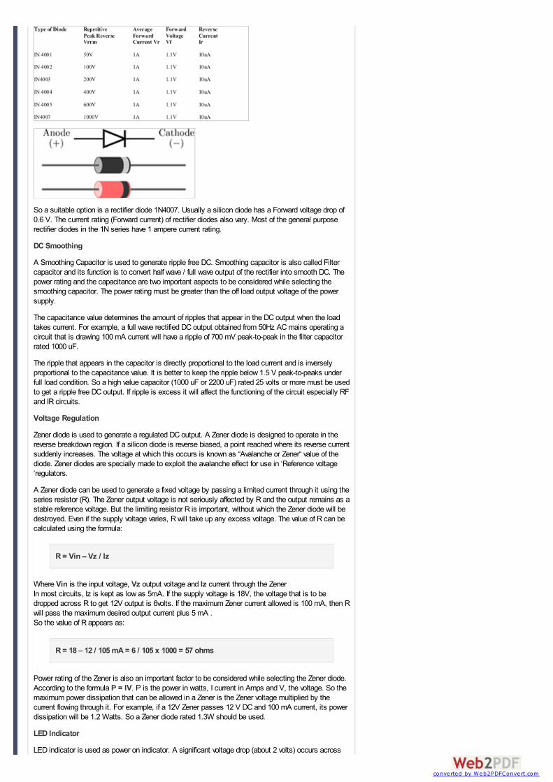


![Medium Voltage Capacitors€¦ · 3 Medium Voltage Capacitors Type MSCE Single Phase Capacitor - Insulation Level 36 kV [50/150] Capacitor without Internal Fuse System Rated Voltage:](https://static.documents.pub/doc/80x56/5ead95020ebe1a1107404c5b/medium-voltage-3-medium-voltage-capacitors-type-msce-single-phase-capacitor-insulation.jpg)


