International Conference on Renewable Energies and Power Quality (ICREPQ’18) Salamanca (Spain), 21 th to 23 th March, 2018 exÇxãtuÄx XÇxÜzç tÇw cÉãxÜ dâtÄ|àç ]ÉâÜÇtÄ (RE&PQJ) ISSN 2172-038 X, No.16 April 2018 Voltage Sourced Converter (VSC) based on multiple FACTS controllers for the improvement of power quality Shazly A. Mohamed 1 , N. Luo 2 , T. Pujol 2 , L. Pacheco 2 1 Department of Electrical Engineering, Faculty of Engineering, South Valley University, Qena, Egypt. 2 Polytechnic School, University of Girona, Campus Montilivi, 17071 Girona, Spain. Corresponding author: N. Luo, phone number: +0034 656475276, e-mail: [email protected]Abstract. This paper deals with the problems of improving power quality in electrical power grids by using multiple FACTS devices like STATCOM, SSSC and UPFC. The present scenario will focus on the working of the various FACTS family under different types of generator faults that can cause any other transmission lines to be overflowed. The simulation analysis of the proposed model being tested for power grid consists of two- area with 500-kV equivalents connected across the transmission line. The effect of active power, reactive power and voltage responses are studied. Key words System stability, FACTS controllers, STATCOM, SSSC, UPFC. 1. Introduction Power quality issues like voltage sags, swells and harmonics may cause system to shut down or tripping of breakers owing to large current imbalances [1-2]. Nowadays, the technical benefits of flexible alternating current transmission system (FACTS) devices have been investigated in areas of power engineering, which have many advantages such as improving the static/dynamic stability and power quality of AC network as well as maintaining system security [3-8]. FACTS family like static synchronous compensator (STATCOM), static synchronous series compensator (SSSC) and unified power flow controller (UPFC) can be connected to a transmission line at any suitable location in series, in parallel, or in a combination of series-parallel [9-12]. This paper aims towards power quality improvement using FACTS controllers to control various parameters of transmission line network. The paper is structured as follows: Section 2 presents the configuration and modeling analysis of various types FACTS controllers. Simulated system modeling without connecting any FACTS device are addressed in Section 3. Test systems, simulation results and discussion are illustrated in Section 4. Finally, research conclusions are given in Section 5. 2. Power Quality Compensation Many compensation techniques for improving the power quality, such as the cancellation of harmonics, optimal placement of capacitor banks/sizing, etc. [13], have been proposed to keep the harmonic voltages and currents within the proposed levels. The FACTS family concept is based on the use of power electronics to solve the power quality problems and to control the active/reactive power flow and the voltage in the transmission network [14]. Power flow is a function of the transmission line impedance, the magnitude of sending/receiving end voltages and the phase angle between them. By controlling one or a combination of power flow arguments, it is possible to control active and reactive flow of power in the transmission line. Figure 1 illustrates a simple power system with impedance connecting between two-area power systems. Suppose that system I is a sending-end with voltage V 1 and system II is a receiving-end with voltage V 2 , β 1 and β 2 are the phase angles of the sending-end and receiving-end voltage sources. Fig. 1: Simplified power system Fig. 2: Vector line diagram https://doi.org/10.24084/repqj16.213 65 RE&PQJ, Vol.1, No.16, April 2018
Transcript
International Conference on Renewable Energies and Power Quality (ICREPQ’18) Salamanca (Spain), 21th to 23th March, 2018
Voltage Sourced Converter (VSC) based on multiple FACTS controllers for the improvement of power quality
Shazly A. Mohamed1, N. Luo2, T. Pujol2, L. Pacheco2
1 Department of Electrical Engineering, Faculty of Engineering, South Valley University, Qena, Egypt. 2 Polytechnic School, University of Girona, Campus Montilivi, 17071 Girona, Spain.
Abstract. This paper deals with the problems of improving power quality in electrical power grids by using multiple FACTS devices like STATCOM, SSSC and UPFC. The present scenario will focus on the working of the various FACTS family under different types of generator faults that can cause any other transmission lines to be overflowed. The simulation analysis of the proposed model being tested for power grid consists of two-area with 500-kV equivalents connected across the transmission line. The effect of active power, reactive power and voltage responses are studied. Key words System stability, FACTS controllers, STATCOM, SSSC, UPFC.
1. Introduction
Power quality issues like voltage sags, swells and harmonics may cause system to shut down or tripping of breakers owing to large current imbalances [1-2]. Nowadays, the technical benefits of flexible alternating current transmission system (FACTS) devices have been investigated in areas of power engineering, which have many advantages such as improving the static/dynamic stability and power quality of AC network as well as maintaining system security [3-8]. FACTS family like static synchronous compensator (STATCOM), static synchronous series compensator (SSSC) and unified power flow controller (UPFC) can be connected to a transmission line at any suitable location in series, in parallel, or in a combination of series-parallel [9-12].
This paper aims towards power quality improvement using FACTS controllers to control various parameters of transmission line network. The paper is structured as follows: Section 2 presents the configuration and modeling analysis of various types FACTS controllers. Simulated system modeling without connecting any FACTS device are addressed in Section 3. Test systems, simulation results and discussion are illustrated in Section 4. Finally, research conclusions are given in Section 5.
2. Power Quality Compensation
Many compensation techniques for improving the power quality, such as the cancellation of harmonics, optimal placement of capacitor banks/sizing, etc. [13], have been proposed to keep the harmonic voltages and currents within the proposed levels. The FACTS family concept is based on the use of power electronics to solve the power quality problems and to control the active/reactive power flow and the voltage in the transmission network [14]. Power flow is a function of the transmission line impedance, the magnitude of sending/receiving end voltages and the phase angle between them. By controlling one or a combination of power flow arguments, it is possible to control active and reactive flow of power in the transmission line. Figure 1 illustrates a simple power system with impedance connecting between two-area power systems. Suppose that system I is a sending-end with voltage V1 and system II is a receiving-end with voltage V2, β1 and β2 are the phase angles of the sending-end and receiving-end voltage sources.
Fig. 1: Simplified power system
Fig. 2: Vector line diagram
https://doi.org/10.24084/repqj16.213 65 RE&PQJ, Vol.1, No.16, April 2018
According to Figures 1 and 2, the equations for describing the active and reactive power flows at the receiving-end and sending-end voltage sources can be written as follows:
==−==∆βασ
βαsinsin
coscos
1
21
VIZV
VVIZV (1)
Z
VjV
Z
VV
Z
VVI
σββ +∆=∠−∠=−= 221121 (2)
For a transmission line connecting buses (1) and (2) with stiff bus voltages β∠1V and 02∠V , the complex power
developed at sending-end side can be calculated as follows:
−
−+
+
−
+=
ββ
ββ
sincos
sincos
2
1
2
122
211
jRV
VjX
XV
VR
XR
VVS
(3)
ββ
ββ
sincos
sincos
2
122
211
2
122
211
RV
VX
XR
VVQ
XV
VR
XR
VVP
−
−
+=
+
−
+=
(4)
Similarly, the complex power developed at receiving-end side can be calculated as follows:
+
−+
−
−
+=
ββ
ββ
sincos
sincos
1
2
1
222
212
jRV
VjX
XV
VR
XR
VVS
(5)
ββ
ββ
sincos
sincos
1
222
211
1
222
212
RV
VX
XR
VVQ
XV
VR
XR
VVP
+
−
+=
−
−
+=
(6)
where V1 and V2 are the values of voltages, β1 and β2 are phase angles of the voltage at buses 1 and 2, respectively.
For simplicity, the voltage phase angles are chosen such that β2 = 0 and the difference between the phase angles is β = β1 – β2 = β1 as depicted in Fig. 3. By putting R = 0 in Eq. 4, the active and reactive power can be written as:
X
VV
X
VQ
X
VVP
ββ cos;
sin 212
11
211 −== (7)
Also from Eq. 6, the active and reactive power can be written as follows:
X
VV
X
VQ
X
VVP
ββ cos;
sin 212
22
212 −=−= (8)
The above active power expressions are equal but in opposite direction, as it is a lossless system R = 0. In this
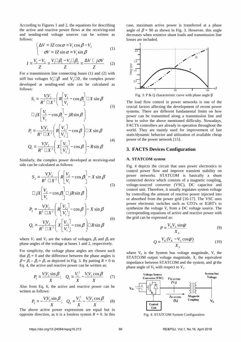
case, maximum active power is transferred at a phase angle of β = 90 as shown in Fig. 3. However, this angle decreases when resistive shunt loads and transmission line losses are included.
Fig. 3: P & Q characteristic curve with phase angle β
The load flow control in power networks is one of the crucial factors affecting the development of recent power systems. There are different fundamental limits on how power can be transmitted along a transmission line and how to solve the above mentioned difficulty. Nowadays, FACTS controllers are already in operation throughout the world. They are mainly used for improvement of fast static/dynamic behavior and utilization of available cheap power of the power network [15]. 3. FACTS Devices Configuration A. STATCOM system
Fig. 4 depicts the circuit that uses power electronics to control power flow and improve transient stability on power networks. STATCOM is basically a shunt connected device which consists of a magnetic coupling, voltage-sourced converter (VSC), DC capacitor and control unit. Therefore, it usually regulates system voltage by controlling the amount of reactive power injected into or absorbed from the power grid [16-17]. The VSC uses power electronic switches such as GTO's or IGBT's to synthesize the voltage Vs from a DC voltage source. The corresponding equations of active and reactive power with the grid can be expressed as:
S
SK
X
VVP
ψsin= (9)
S
SKK
X
VVVQ
)cos( ψ−= (10)
where Vk is the System bus voltage magnitude, Vs the STATCOM output voltage magnitude, Xs the equivalent impedance between STATCOM and the system, and ψ the phase angle of Vk with respect to Vs .
Fig. 4: STATCOM System Configuration
https://doi.org/10.24084/repqj16.213 66 RE&PQJ, Vol.1, No.16, April 2018
If Vs > Vk then the reactive current flows from the converter to the AC system through the magnetic coupling by injecting reactive power to the AC system. If Vs < Vk then current flows from AC system to the converter by absorbing reactive power from the system. Finally, if Vs = Vk then there is no exchange of reactive power. The amount of reactive power exchange can be written as:
S
SKK
X
VVVQ
)( −= (11)
B. SSSC System
SSSC employs a voltage sourced converter serially connected to a transmission line through an insertion transformer as illustrated in Fig. 5. SSSC operates in the similar way as the STATCOM device, but it is connected in series instead of parallel [18-19].
Fig. 5: SSSC System Configuration
When operated with the proper energy supply, the SSSC can inject a voltage component being of the same value but opposite in phase angle with the voltage developed across the line. The SSSC is typically applied to correct the voltage during a fault in the power grid. However, it has several advantages during normal state such as power factor correction, power flow control and harmonic distortion reduction by active filtering [20]. The active transmission power flow can be expressed as follows:
X
VP
γsin2
= (12)
with V being the sending and receiving end voltages (assuming V = VS = VR), X the equivalent impedance of the line, and γ the power angle.
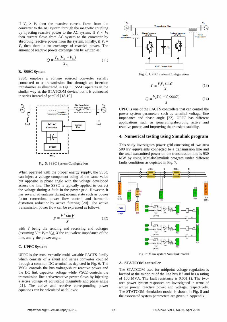
C. UPFC System
UPFC is the most versatile multi-variable FACTS family which consists of a shunt and series converter coupled through a common DC terminal as depicted in Fig. 6. The VSC1 controls the bus voltage/shunt reactive power and the DC link capacitor voltage while VSC2 controls the transmission line active/reactive power flows by injecting a series voltage of adjustable magnitude and phase angle [21]. The active and reactive corresponding power equations can be calculated as follows:
Fig. 6: UPFC System Configuration
X
VVP
αsin21= (13)
X
VVVQ
)cos( 112 α−= (14)
UPFC is one of the FACTS controllers that can control the power system parameters such as terminal voltage, line impedance and phase angle [22]. UPFC has different applications such as generating/absorbing active and reactive power, and improving the transient stability.
4. Numerical testing using Simulink program
This study investigates power grid consisting of two-area 500 kV equivalents connected to a transmission line and the total transmitted power on the transmission line is 930 MW by using Matlab/Simulink program under different faults conditions as depicted in Fig. 7.
Fig. 7: Main system Simulink model
A. STATCOM controller
The STATCOM used for midpoint voltage regulation is located at the midpoint of the line bus B2 and has a rating of 100 MVA. The fault resistance is 0.001 Ω. The two-area power system responses are investigated in terms of active power, reactive power and voltage, respectively. The STATCOM simulation model is shown in Fig. 8 and the associated system parameters are given in Appendix.
https://doi.org/10.24084/repqj16.213 67 RE&PQJ, Vol.1, No.16, April 2018
Fig. 8: STATCOM system simulation model
Fig. 9 illustrates the reference voltage Vref along with the measured positive-sequence voltage Vm at the STATCOM bus and the reactive power Qm which is absorbed (+Ve) value or generated (-Ve) value by the STATCOM.
Fig. 9: Performance of STATCOM
Fig. 10 illustrates the system responses under three-line fault. In this case, the active power generated from the system without STATCOM is more than the system with STATCOM. Also, the reactive power generated from the system with STATCOM is higher than the system without STATCOM, because the active power is decreased.
Fig. 10: Active, reactive power and voltage response
B. SSSC Controller
The system model with SSSC has been simulated in Matlab/Simulink environment as depicted in Fig. 11.
Fig. 11: SSSC system simulation model
With the system running under different fault conditions for the SSSC device. The fault resistance was 0.001 Ω. The SSSC is located in series with the line and has a rating of 100 MVA. The two-area power system responses are investigated here in terms of the active power, reactive power and voltage, respectively. The parameters of SSSC system is in Appendix. Fig. 12 illustrates the reference voltage Vqref along with the measured injected voltage Vqinj by the SSSC and the active power flow of the SSSC system.
https://doi.org/10.24084/repqj16.213 68 RE&PQJ, Vol.1, No.16, April 2018
Fig. 12: Performance of SSSC
Fig. 13 illustrates the system responses under three-line fault. The active power generated from the system without SSSC is more than that with SSSC and the reactive power generated from the system with SSSC is more than that without SSSC, because the active power is decreased.
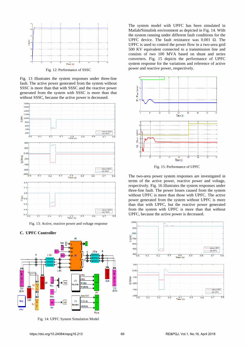
Fig. 13: Active, reactive power and voltage response C. UPFC Controller
Fig. 14: UPFC System Simulation Model
The system model with UPFC has been simulated in Matlab/Simulink environment as depicted in Fig. 14. With the system running under different fault conditions for the UPFC device. The fault resistance was 0.001 Ω. The UPFC is used to control the power flow in a two-area grid 500 KV equivalent connected to a transmission line and consists of two 100 MVA based on shunt and series converters. Fig. 15 depicts the performance of UPFC system response for the variations and reference of active power and reactive power, respectively.
Fig. 15: Performance of UPFC
The two-area power system responses are investigated in terms of the active power, reactive power and voltage, respectively. Fig. 16 illustrates the system responses under three-line fault. The power losses caused from the system without UPFC is more than those with UPFC. The active power generated from the system without UPFC is more than that with UPFC, but the reactive power generated from the system with UPFC is more than that without UPFC, because the active power is decreased.
https://doi.org/10.24084/repqj16.213 69 RE&PQJ, Vol.1, No.16, April 2018
Fig. 16: Active, reactive power and voltage response
5. Conclusions
This work has studied the improvement of power quality in a two-area interconnected power system under different fault conditions in terms of active power, reactive power and voltage responses. The modeling, analysis and simulation of the above scenario, with or without FACTS family STATCOM, SSSC and UPFC controllers, have been done by using MATLAB/Simulink program. The numerical results have shown that the FACTS family controllers can improve effectively power quality, reduce the power losses, and are faster as compared to systems without FACTS controllers. The future work will be oriented towards applying hybrid FACTS family and the associated optimal location based control techniques for the improvement of power quality.
APPENDIX
Design Parameters:
• Rating of STATCOM = 100 MVA with system frequency = 50 Hz and source voltage = 500 kv.
• Transmission line length = 600 km, Total impedance of STATCOM = 0.22 pu and Capacitance = 375 µf
• DC link voltage = 40 kV and Frequency modulation = 1.68 kHz
• Proportional gain = 5 and Integral gain = 1000
• Rating of SSSC = 100 MVA, Rating of UPFC = 500 Kv and 100 MVA
REFERENCES
[1] K. Praveen, A. Nishant, M. Devendra M., "Improvement in
power system stability with the implementation of Facts devices", Int. J. Advanced Technology & Engineering Research, 3, 2, 45-60, 2014.
[2] K. Devender, S. Balwinder, "Transient stability of a multi machine power system", Int. J. Engineering and Advanced Technology, 2, 4, 2013.
[3] B. Rao, P. Chanti, N. Lavanya, S. Sekhar, Y. Kumar, "Power system stability enhancement using Fact devices", Int. J. Engineering Research and Applications, 4, 4, 339-344, 2014.
[4] A. Kazemi, F. Mahamnia, “Improving of transient stability of power systems by supplementary controllers of UPFC using different fault conditions”, WSEAS Transactions on Power Systems, 3, 7, 547-556, 2008.
[5] A. El-Noby, G. Mohamed, M. Hamada, Y. Mobarak, M. Wahab, M. Abdel, “Robust technique LFC of two-area power system with dynamic performance of combined SMES and SSSC Control”, Int. J. Advances in Engineering & Technology, 8, 2, 46-58. Apr., 2015.
[6] Shazly A. Mohammed, M. Abdel-Moamen, B. Hasanin, “Analysis, modeling and simulation of dynamic voltage restorer DVR for compensation of voltage-quality disturbances”, Int. J. Control, Automation and Systems, 1, 2, 23-29, 2013.
[7] M. Bhaskar, S. Dash, C. Subramani, M. Kumar, P. Giresh, M. Kumar, “Voltage quality improvement using DVR”, Int. Conf. Recent Trends in Information, Telecommuni-cation and Computing, 378-380, 2010.
[8] Shazly A. Mohammed, A. Cerrada, M. Abdel-Moamen, B. Hasanin, “Dynamic Voltage Restorer (DVR) system for compensation of voltage sags, state-of-the-art review”, Int. J. Computational Eng. Research, 3, 1, 177-183, 2013.
[9] A. Seifi, S. Gholami, A. Shabanpour, “Power flow study and comparison of FACTS: series (SSSC), shunt (STATCOM), and shunt-series (UPFC)”, The Pacific Journal of Science and Technology, 11, 1, 129-137, 2010.
[10] M. Waqar, N. Khan, M. Adnan, W. Khalid, M. Fazal, “Transient stability improvisation in power system by utilizing the concepts of UPFC, STATCOM and SSSC”, Int. J. Scientific & Eng. Research, 7, 10, 841-869, 2016.
[11] G. Ketan, M. Dipesh, A. Vinesh, G. Hirenkumar, “Compa-rison of Different Fact Devices”, Int. J. Science Technology & Engineering, 1, 1, 12-17, 2014.
[12] S. Akter, A. Saha, P. Das, “Modelling, simulation and comparision of various FACTS devices in power system”, Int. J. Engineering Research &Technology, 1, 2012.
[13] M. Yousefikia, E. Gharibreza, M. Baledi, “Reliability and power quality improvement of microgrids by fault current limiter”, J. Academic and Applied Studies, 6, 33-44, 2016.
[14] V. Mathad, B. Ronad, S. Jangamshetti, “Review on comparison of FACTS controllers for power system stability enhancement”, Int. J. Scientific and Research Publications, 3, 3, 1-4, 2013.
[15] B. Rao, P. Chanti, N. Lavanya, S. Sekhar, Y. kumar, “Power system stability enhancement using FACTS devices”, Int. J. Engineering Research and Applications, 4, 339-344, 2014.
[16] K. Sergey, P. Georg, S. Heino, “Comparison of modern STATCOM and synchronous condenser for power transmission systems”, IEEE Electrical Power and Energy Conference, 2016.
[17] R. Jadeja, S. Patel, S. Chauhan, “STATCOM – a preface to power quality in power systems performance”, Engineering, Technology & Applied Science Research, 6, 1, 895-905, 2016.
[18] R. Pawn, R. Thakre, “Comparative study of power system stability enhancement of various IEEE Bus System using SSSC”, Int. J. Engineering Research & Technology, 5, 2, 359-363, 2016.
[19] C. Hiwarkar, P. Burade, “Voltage stability enhancement of power system using STATCOM and SSSC”, Int. J. Recent and Innovation Trends in Computing and Communication, 4, 5, 316-320, 2016.
[20] S. Taha, M. Saad, “Effects of a static synchronous series compensator (SSSC) based on a soft switching 48-pulse PWM inverter on the power demand from the grid”, Journal of Power Electronics, 10, 1, 85-90, 2010.
[21] B. Rajan, S. Sankar, M. Padmarasan, S. Saravanakumar, “Simulation of open and closed loop controlled UPFC systems”, Int. Conf. Emerging Trends in Electrical Engineering and Energy Management, 2013.
[22] C. Hirdesh, P. Abhishek, J. Gaurav, “UPFC Based wind energy efficient system”, Int. J. for Research in Applied Science & Engineering Technology, 3, 157-163, 2015.
https://doi.org/10.24084/repqj16.213 70 RE&PQJ, Vol.1, No.16, April 2018