FINAL REPORT VOLUME 1 EXECUTIVE SUMMARY DEFINITION OF AVIONICS CONCEPTS FOR A HEAVY LIFT CARGO VEHICLE for Marshal Space Flight Center Contract Number NAS8-37578 September 1989 GENERAL OYNAMICS Space Systems Division • /# https://ntrs.nasa.gov/search.jsp?R=19900004913 2018-06-23T02:40:43+00:00Z
Transcript
FINAL REPORT
VOLUME 1EXECUTIVE SUMMARY
DEFINITION OF AVIONICS CONCEPTSFOR A HEAVY LIFT CARGO VEHICLE
Final Report, Volume 1 Definition of Avionics Concepts for a Heavy Lift Car_fo Vehicle
1.0 INTRODUCTION
The Executive Summary, (Volume 1, Final Report), was developed by the Space SystemsAvionics Group of General Dynamics. It satisfies the requirements of Data Requirement 4 ofthe "Definition of Avionics Concepts for a Heavy Lift Cargo Vehicle" study for the Marshall
Space Flight Center under contract NAS8-3578.
1.1 SCOPE
This document contains a summary of:• Significant achievements and activities of the study effort.• Results, methodologies and selected options• Trade Studies, recommended approaches,design impacts and analysis
. Cost estimates of major elements of the Ground Based Testbed.
1.2 BACKGROUND
The HLCV avionics study was originally meant to focus the development of advancedavionics systems for the next ten to fifteen years. Figure 1.2-1 shows the role the HLCV
Avionics study was envisioned to play. Scoped to start with an expendable, Shuttle derivedbooster, it was to define an optimum progression of upgrades and transitions until a fullyreusable fixed wing booster system was achieved. Not limited to boosters, the study was toexplore second stages, recoverable modules, and the attendant ground support systems.
- FIGURE 1.2-1 HLCV AVIONICS STUDY: FOCUS FOR AVIONICS ADVANCED DEVELOPMENT
Page 1 9/27/89, 8:43 AM
Final Report, Volume 1 Definition of Avionics Concepts for a Heavy Lift Car_lo Vehicle
r PREL DESIGN 1HLCV AVIONICS
P%,ogS,G.
_LONG LEADIMPLEMENTATION
• HW PROC
FAC MODS
• UTILIZATION OFIN-HOUSECAPABILITIES
CODE y CONTRACTOR
7 INHOUSE (MSFC)
_7 INHOUSE WITH SUPPORTOF INTEGRATION CONTRACTOR
DESIGN/BUILDMAST (O1)
• INSTALLATION
• INTEGRATION
• SOFTWARE
• DEMONSTRATION
OMPLETION OF IHARDWARE
ROCUREMENT
Yr,,,,-tl
EXPAND MASTCAPABILITIES
(02)
7
I//sSU PPORT
HUTTLE-C I
SUPPORT I
STV I
ALS I
SH-C EVOL I
FIGURE 1.2-2 HLCV / GBT IMPLEMENTATION
Methods for accelerating the application of beneficial new technologies to existing and futuresystems were needed. To this end, a Ground Based Testbed was to be defined. Though nota stated goal, lowering the overall cost per pound of orbiting a payload drove the study toinclude the definition of the optimal mix of ground and airborne check out capability.Autonomous operation of the far term vehicles was felt to be a logical goal.
Shortly after the first review, the customer directed a shift in emphasis to the definition of theGround Based Testbed, (GBT), that would support development of the HLCV avionicsystems. The HLCV reference vehicle avionic systems were defined to the level required tosize the GBT main processor, G&N Extension, and interconnecting busses and networks.
A target implementation schedule was provided by MSFC in October linking the HLCV GBTand.the Marshall Avionics System Test bed (MAST) efforts (see Figure 1.2-2.). Also definedwere specific functional support levels with dates and projected budget allocations Acandidate site for the GBT/MAST was also provided The third Quarter Review reflected theseinputs and specifically costed the Phase 1 lab configuration. For purposes of this study theterms MAST and GBT are synonymous.
The Executive Summary was structured to parallel the presentation at the 4th QuarterReview. It is intended to supplement the presentation and contains back-up information notincluded in the presentation materials.
1.2.1 STUDY OBJECTIVES
The initial objectives of the study were enumerated in the Study Plan as:
Page 2 9/27/89, 8:43 AM
Final Report, Volume 1 Definition of Avionics Concepts for a Heavy Lift Cargo Vehicle
1. Define the avionics requirements and recommended avionics concepts foran expendable Heavy Lift Cargo Vehicle in the 1992-1995 time span.
2. Define the avionics requirements and recommended avionics concepts for ahighly reusable HLCV to be operational in the 2000 era.
13. Define the requirements, concepts, developmental plans, and costs for an
avionics test bed(s). The avionics test bed will support the development
and testing of the recommended vehicle and vehicle support components,software modules T subsystems and systems.
4. Develop a transition plan from the expendable to the highly reusable HLCV.
5. Develop a follow-on plan to define advanced development activities.
As previously stated, the study emphasis shifted to definition of the avionics test bed,Objective #3, shortly after the first Quarterly review. Details were hammered out in the AugustTechnical Interchange Meeting (TIM). The study plan was changed and a no-cost contractual
change initiated to offset the additional tasks and products associated with this change,objectives 4 and 5 were rescoped and de-emphasized.
1.2.2 STUDY TASKS & SCHEDULE
Figure 1.2.2-1 is the revised Master Schedule that reflects the final contract changes. The sixmajor task classifications are shown and the deliverables identified.
L ._---3 r....................... _ ...... _j •_ r • ,m, B"
qllP •
qP •
• V • •
FIGURE 1.2.2-1 REVISED
• q•
F mqP
'qr U_W• Up • U' •
_ mw
MASTER SCHEDULE
_lP drl¢
"1
P
I
_B
vqWv• V
W
Page 3 9/27/89, 8:43 AM
Final Report, Volume 1 Definition of Avionics Concepts for a Heavy Lift Cargo Vehicle
2.0 GBT DESIGN OBJECTIVES AND PHILOSOPHY
The GBT is envisioned as a general resource facility providing to new vehicle programs acost effective method of evaluating the concepts and technologies employed in their design.This resource will permit complete end-to-end simulations of system operation in thesimulated mission environment desired.
The GBT is to be set up to encourage use by all HLCV era vehicles during their initial designphases. Review of past projects involving total vehicle or subsystem development haverepeatedly shown the need for such a readily accessible and powerful test and evaluationfacility. The traditional dedicated test and development facilities have not been able tosupport their projects early enough to optimize system requirements and design. Newprojects must initially use facilities dedicated to other projects. Seldom do such facilitiesprovide all the necessary testing capabilities or time for the required work.
The key to the HLCV GBT success is seen to simply be: Cost Effectiveness. To obtain thisobjective, the Lab must be readily accessible at the time when new projects traditionally don'thave their own dedicated facilities. GBT access must be simple and bound with a minimum ofred tape. Once accessed, the GBT must provide a user friendly environment, anenvironment that can quickly be configured to access the required testing and loggingresources. The resources must be capable of evaluating the concepts, technologies ordesigns to the required level of accuracy and against recognized performance benchmarks.Finally, the GBT must provide not only easy replication of the testing, but also provide theability to thoroughly analyze the results and report the results in forms which effectivelycommunicate their significance.
2.1 GBT OBJECTIVES
The major objectives for the GBT are to provide a cost effective, multiuser simulation, test anddemonstration facility to:
1. Support early development and quantitative evaluation of proposed avionics systemsduring the early phases, (phase A/B),of a program.• surfaces avionics, systems, integration and software problems early• supports early requirement s development
2. Accelerate new avionics technology testing and application to future programs.3. Provide a productivity center for evaluating/demonstrating major new design advances
from NASA and industry.4. Promote continuity of avionics architectures, software, and hardware across projects.5. Demonstrate the "integration-ability" of new subsystems or components and their
impact on the performance of an existing vehicle system.
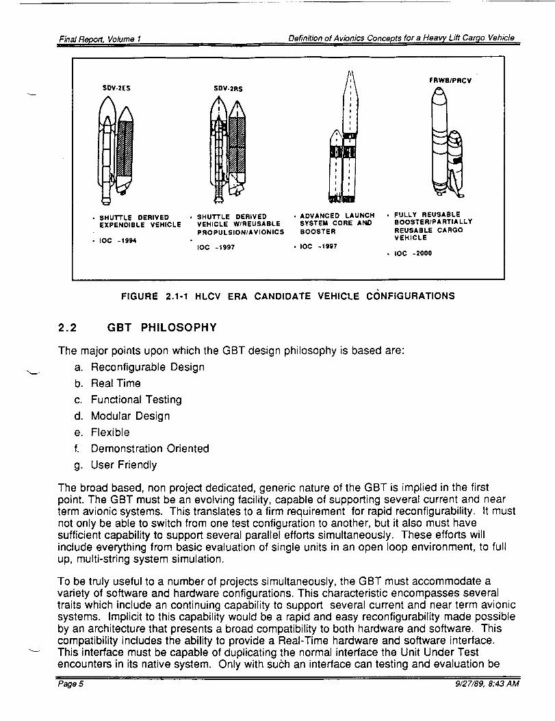
Figure 2.1-1 shows four HLCV era vehicles to be supported by the GBT. The first two areshuttle derived vehicles, SDV-2ES and SDV-2R. The 2R version has reusable propulsionand avionics as opposed to being expendable as the 2ES is. An alternative to the SDV-2RSis the Advanced Launch System Core and Booster. The fourth GBT supportable vehicleshown is the Fully Reusable Booster/Partially Reusable Cargo Vehicle, FRWB/PRCV. Inaddition to these, the GBT will also support upper stages, the Space Transfer vehicles, andseveral payloads.
Page 4 9/27/89, 8:43 AM
Final Report, Volume I Definition of Avionics Concepts for a Heavy Lift Car_o Vehicle
SOV.2ES
• SHUTTLE DERIVEDEXPENDIBLE VEHICLE
• IOC -1994
SDV.2RS
• SHUTTLE DERIVEDVEHICLE W/REUSABLE
PROPULSION/AVIONICS
IOC -1997
I
i I
: I
I
!
I
ila
• ADVANCED LAUNCHSYSTEM CORE AND
BOOSTER
• IOC -1997
FRWBIPRCV
• FULLY REUSABLEBOOSTER/PARTIALLY
REUSABLE CARGOVEHICLE
• IOC -2000
FIGURE 2.1-1 HLCV ERA CANDIDATE VEHICLE C(_NFIGURATIONS
2.2 GBT PHILOSOPHY
The major points upon which the GBT design philosophy is based are:
a. Reconfigurable Design
b. Real Time
c. Functional Testing
d. Modular Design
e. Flexible
f. Demonstration Oriented
g. User Friendly
The broad based, non project dedicated, generic nature of the GBT is implied in the firstpoint. The GBT must be an evolving facility, capable of supporting several current and nearterm avionic systems. This translates to a firm requirement for rapid reconfigurability. It mustnot only be able to switch from one test configuration to another, but it also must havesufficient capability to support several parallel efforts simultaneously. These efforts willinclude everything from basic evaluation of single units in an open loop environment, to fullup, multi-string system simulation.
To be truly useful to a number of projects simultaneously, the GBT must accommodate avariety of software and hardware configurations. This characteristic encompasses severaltraits which include an continuing capability to support several current and near term avionicsystems. Implicit to this capability would be a rapid and easy reconfigurability made possibleby an architecture that presents a broad compatibility to both hardware and software. Thiscompatibility includes the ability to provide a Real-Time hardware and software interface.This interface must be capable of duplicating the normal interface the Unit Under Testencounters in its native system. Only with suc:h an interface can testing and evaluation be
Page 5 9/27/89, 8:43 AM
Final Report, Volume 1 Definition of Avionics Concepts for a Heavy Lift Cargo Vehicle
carried out at the required level of fidelity. Just as important is the ability to preciselymanipulate the interface characteristics. Fault insertion and off limit operation can enhancethe thoroughness of testing.
The GBT is modular at all functional levels so, as it develops and the support requirements
change, the lab can add or access the required resources. This translates to the GBT beingable to accommodate any vehicle or system simulation of similar complexity to the thencurrent defined reference vehicle and systems. Modular design in both the GBTs hardwareand software facilitate an orderly expansion of capability. The foundation of hardware modelbenchmarks will be validated against real equipment. Once proven, a combination of realand simulated hardware models can be utilized to evaluate any number of proposed systemarchitectures.
Since one of the GBTs primary functions is to provide timely support to new projects, it musthave the ability to quickly adapt to the specific needs of those projects. This flexibility must bea basic consideration in the GBT architecture so it can perform that level of testing orsimulation required in a more cost effective manner than currently available to new projects.
The current implementation plan for GBT establishes an August 1990 IOC to support Shuttle-C, (figure 1.2-2). In actuality, the GBT will have more than half of its total planned capability atthis point. The software tools and models developed for the Shuttle-C are basically genericin nature, with separate data files supplying the unique values for this vehicle, its subsystems,and mission profiles. In most cases, only data set value changes would be required to switchfrom one vehicle configuration to another.
3.0 TRADE STUDIES AND TECHNICAL ANALYSIS
Several technical issues had to be resolved prior to the definition of the three HLCV avionicsystem designs and the Ground Based Test Bed.
The range of studies originally considered covered the three HLCV reference vehicles andthe GBT. Those chosen for further study included:
• RVU replacement of EIU• Vehicle Processors• Software Language and Tool selection• Flight Control Actuators• Vehicle Power• Lab Architecture• Data Buses and High Speed Networks
3.1 ENGINE INTERFACE UNIT REPLACEMENT
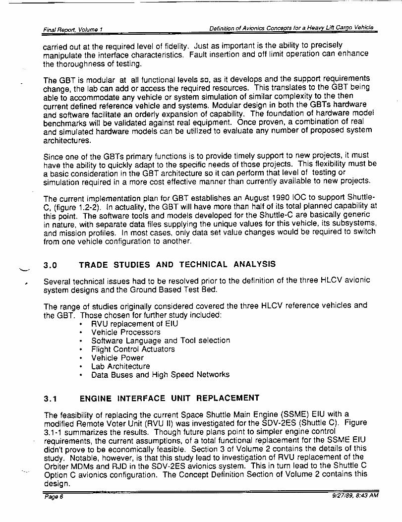
The feasibility of replacing the current Space Shuttle Main Engine (SSME) EIU with amodified Remote Voter Unit (RVU II) was investigated for the SDV-2ES (Shuttle C). Figure3.1-1 summarizes the results. Though future plans point to simpler engine controlrequirements, the current assumptions, of a total functional replacement for the SSME EIUdidn't prove to be economically feasible. Section 3 of Volume 2 contains the details of thisstudy. Notable, however, is that this study lead to investigation of RVU replacement of theOrbiter MDMs and RJD in the SDV-2ES avionics system. This in turn lead to the Shuttle COption C avionics configuration. The Concept Definition Section of Volume 2 contains thisdesign.
Page 6 9/27/89, 8:43 AM
Final Report, Volume I Definition of Avionics Concepts for a Heavy Lift Cargo Vehicle
RVU II
EIU
:rECURRINGCOSTS
SAME
SAME
RECURRINGOPER.COSTS
same as:
other
units
uniqueunit &
test
NON-RECURRING
COSTS
SAME
SAME
PERFORMANCEMfq REG
HIGH
HIGH
PERFORMANCEGROWTH
HIGH
LIMITED
RELIABILITY
HIGHER
LOW
RISK
FACTOR
HIGH
LOW
• THE ABOVE ARE RANKED IN ORDER FROM HIGHEST TO LOWEST
• NO ADVANTAGES IN GOING WITH THE RVU II
NOTE: Reduced Engine Control Requirements may alter conclusion.
FIGURE 3.1-1. RVU II-EIU TRADE STUDY RESULTS
3.2 VEHICLE PROCESSORS
Selection of the best current CPU for the HLCV centered about the 16 bit, 1750 processors.Figure 3.2-1 shows the units investigated. The PSC 1750A was selected. 32 bit processorswere also considered for far term application.
Availability Risk Cost Perlormance
Existing PSC 88
PACE 1750A now
Improved PSC
RCA CMOS/SOS TBD
PSC 1750A
:_CA CMOS/SOS 1750A 88
HI RICMOS GVSC 8 9
Self-Checking PSC now
PAC E 1750A
LSI Logic L64500 now
UTMC 1750A now
MACDAC 281 TBD
Fairchild F9450 Now
Mikros M2750 Future
TISLC 1750A TBD
PACE II 1750A Near Term
CDC 444 1750
CMC_ _ Near Term
LowestL
Vloderate
High
vloderate
High
3west
TBD
High
TBD
TBD
Low
TBD
TBD
TBD
TBD
TBD
TBD
1 .3-2.6
1 .3-2.6
High
2.8
1.1 -3.7
1 - 2
900k
750k
600k
700K
High
High
3.5 MIPS at 40M Hz
3 - 4 MIPS
USE Rating
Ai r Ground Lab
q
q
q
q
,j
Best
Iii
Lo_t
FIGURE 3.2-1. TECHNOLOGY MATRIX - 1750 PROCESSORS
Page 7 9/27/89, 8:43 AM
Final Report, Volume 1 Definition of Avionics Concepts for a Heavy Lift Car_lo Vehicle
3.3 COMPUTER LANGUAGES
Nine criteria were examined in selection of the software language to be used in the GBT,Vehicle, and ground Checkout facilities. Figure 3.3-1 summarizes these results. Ada waschosen with "C" selected for usein special test equipment and small simulations untilsoftware and tools become available in Ada.
Ada
Jovial
HAL/S
Assembly
"C"
Fortran
Goal
Dist.Ada
Compatability Availability Risk
Excellent
Good
Poor
Good
Very Good
Poor
TBD
Now
Now
Now
Now
Now
Now
Now
Near
PERFORMANCECost Lines of
Speed I Code
Low Low Very Gooc Low
Low Moderate Good Low
Low Moderate Very GooC Low
Low Very High Excellent Highest
Low Low Good Low
High Good Moderate,
Low High Moderate Moderat_
Low Lowest Excellent Low
USE
iGround ILab Rating
q q
,J q
q ,J
Excellent
Good
Acceptable
Acceptable
Excellent
Good
Acceptable
•J .jVery Good
FIGURE 3.3-1. TECHNOLOGY MATRIX - COMPUTER LANGUAGES
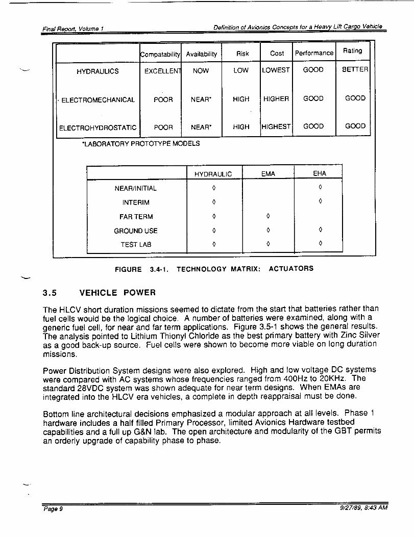
3.4 FLIGHT CONTROL ACTUATORS
The large Thrust Vector Control, (TVC) actuators proved to be the major area of concern in
the developing area of Flight Control Actuators. Mid and Far Term vehicles will employsignificantly more engines. The five primary ascent engines of the Shuttle will give way toclustered engine configurations using 14 to 20 engines on some future applications. Theimpact to ground processing and maintenance look to be intolerable if hydraulic actuatorsare retained. Electromechanical and Hyrostatic actuators present a better potential. LargeEMAs, of the 50+ Horsepower range required, are still in development. Though controlsystem design is adequate, development is needed in the power supply and distributionsystem areas. Figure 3.4-1 shows the three types of actuators investigated.
Recommendations included the retention of hydraulic actuators on near-term vehicles thatstill had relatively few engines. Design provisions should be made, even on these vehicles,
for replacement with EMAs in the future. Emphasis on EMA and ancillary systemdevelopment was felt to be imperative in light of the potential savings in maintenance,production and ground operations costs. Performance gains were felt possible, particularlyin reusable, clustered engine configurations. Here the potential weight savings andincreases in system reliability are significant.
Page 8 9/27/89, 8:43 AM
Final Report, Volume 1 Definition of Avionics Concepts for a Heavy Lift Car_lo Vehicle
HYDRAULICS
ELECTROMECHANICAL
ELECTROHYDROSTATIC
Compatability
EXCELLEN t
POOR
POOR
Availability
NOW
NEAR*
NEAR*
Risk
LOW
HIGH
HIGH
Cost
LOWEST
HIGHER
HIGHEST
Performance
GOOD
GOOD
GOOD
*LABORATORY PROTOTYPE MODELS
N EAR/I N ITIA L
INTERIM
FAR TERM
GROUND USE
TEST LAB
HYDRAULIC EMA
<)
0
0
EHA
<)
0
0
Rating
BETTER
GOOD
GOOD
FIGURE 3.4-1. TECHNOLOGY MATRIX: ACTUATORS
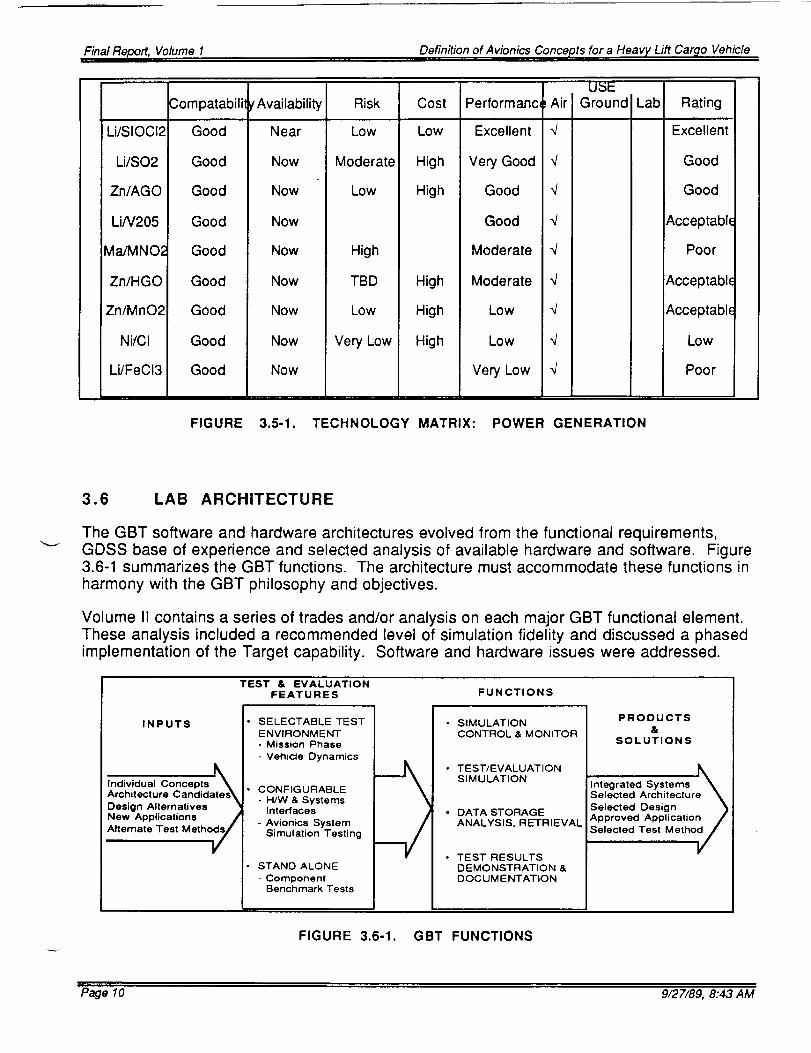
3.5 VEHICLE POWER
The HLCV short duration missions seemed to dictate from the start that batteries rather than
fuel cells would be the logical choice. A number of batteries were examined, along with ageneric fuel cell, for near and far term applications. Figure 3.5-1 shows the general results.The analysis pointed to Lithium Thionyl Chloride as the best primary battery with Zinc Silveras a good back-up source. Fuel cells were shown to become more viable on long durationmissions.
Power Distribution System designs were also explored. High and low voltage DC systemswere compared with AC systems whose frequencies ranged from 400Hz to 20KHz. Thestandard 28VDC system was shown adequate for near term designs. When EMAs areintegrated into the HLCV era vehicles, a complete in depth reappraisal must be done.
Bottom line architectural decisions emphasized a modular approach at all levels. Phase 1
hardware includes a half filled Primary Processor, limited Avionics Hardware testbedcapabilities and a full up G&N lab. The open architecture and modularity of the GBT permitsan orderly upgrade of capability phase to phase.
Page 9 9/27/89, 8:43 AM
Final Report, Volume I Definition of Avionics Concepts for a Heavy Lift Cargo Vehicle
The GBT software and hardware architectures evolved from the functional requirements,GDSS base of experience and selected analysis of available hardware and software. Figure3.6-1 summarizes the GBT functions. The architecture must accommodate these functions in
harmony with the GBT philosophy and objectives.
Volume II contains a series of trades and/or analysis on each major GBT functional element.These analysis included a recommended level of simulation fidelity and discussed a phasedimplementation of the Target capability. Software and hardware issues were addressed.
TEST & EVALUATION
FEATURES
i_,
INPUTS I" SELECTABLE TEST
/ENVIRONMENT
- Mission Phase
- Vehicle Dynamics
Individual Concepts I_ I.
Architecture Candidates_J" CONFIGURABLE
Design Alternatives _J " InterfacesH/W& Systems
New Applications Jr]- Avionics System
Alternate Test Metho[_/' I Simulation Testing
L• STAND ALONE
- Component
Benchmark Tests
FUNCTIONS
• SIMULATION
CONTROL & MONITOR
• TEST/EVALUATION
SIMULATION
• DATA STORAGE
ANALYSIS, RETRIEVAL
• TEST RESULTS
DEMONSTRATION &
DOCUMENTATION
PRODUCTS
&
SOLUTIONS
Integrated Systems
Selected Architecture
Selected Design
Approved Application /
Selected Test Metho_
FIGURE 3.6-1. GBT FUNCTIONS
Page 10 9/27/89, 8:43 AM
Final Report, Volume 1 Definition of Avionics Concepts for a Heavy Lift Car_lo Vehicle
3.7 DATA BUSES & HIGH SPEED NETWORKS
Closed-loop, real time, high fidelity simulations are basic to GBT success. The properselection of data bussed and high speed networks for data transfer and sharing betweenGBT elements not only required establishment of throughput but also a survey of currentlyavailable products. Volume II Section 2 covers this study. Figure 3.7-1 shows the four basictypes of busses in the GBT. Phase 1 bus selection includes 1553 for the vehicle bus, Pronet80 for the communications and control bus and VME Bus for the DMA bus.
FUNCTION - Simulates Vehicle Systems and Maintenance Bus Traffic/Operations
* 1553 - 1 MBS
o 1773 FIBER-OPTIC- 1 MB/S
- FUTURE BUSSES-- HSDB, ETC 50 MB/s
. :: ...._ INSTRUMENTATION BUS - .- -- ....... .-
FUNCTION - Simulates Vehicle Instrumentation and Sensor Busses
• Speed - 1-100 MB/S
lllrlllllmlllllllllllllllllllllllllllllllllllHIIllll IIIIIIIIIIIIIIIIIIIIIIIIIIIIIIIIIHIIIIIIIIIIIDFUNCTION - Data Transfer and Simulation Control
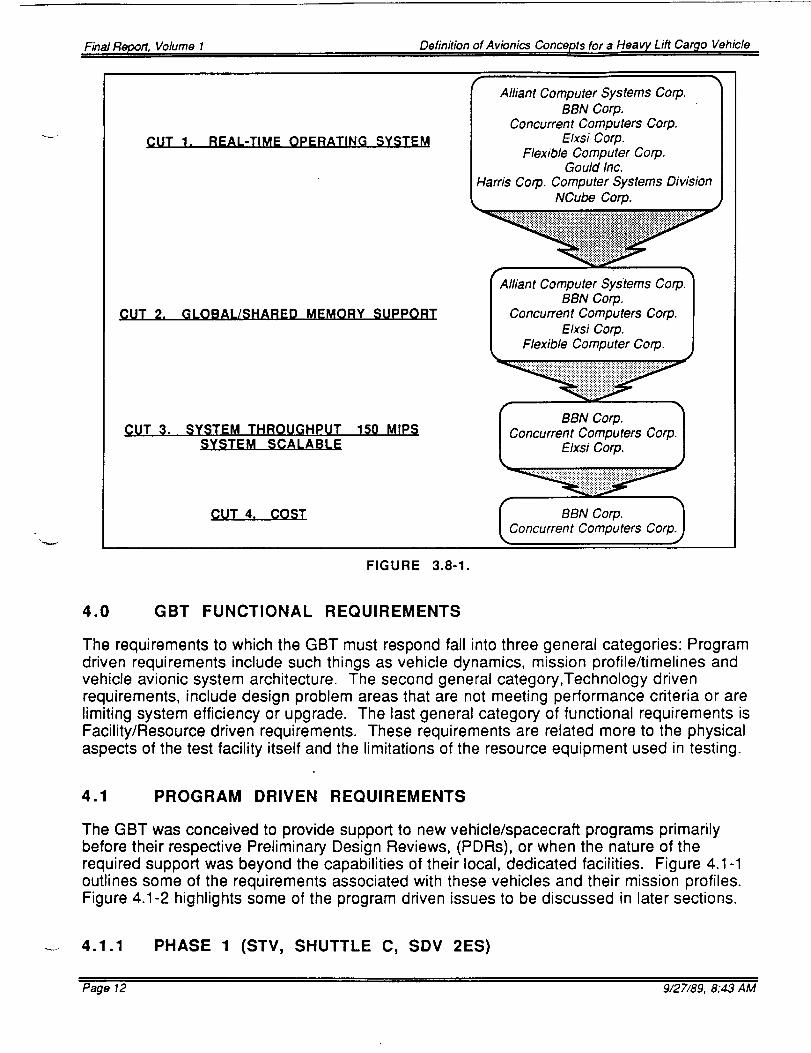
With the shift of emphasis to design of the GBT, selection of the primary lab processor took onadded importance. The scope of the trade study used to determine the performancecharacteristics of this unit and the attendant survey of potential vendors required a specialeffort. A technical demonstration was conceived that would permit a performancecomparison of those processors and their software tools thought capable of fulfilling the basicrequirements. The test would involve tasks similar to those planned for the GBT and useprograms supplied by both the customer and GDSS.
The initial selection process of potential processors considered about 20 candidates. Figure3.8-1 shows some of the selection criteria and the candidates that fulfilled the criteria. The
"paper study" was followed up with a hand-to-hand performance comparison. Threebenchmarks were selected to evaluate the processors and their attendant software tools.The first benchmark was from MSFC and was a mature Fortran coded model of the SSME.
The second was provided by GDSS and was a modular model of the ALS avionics systemcoded in "C". The third benchmarks were industry standards chosen by the participants.
The final phase of the tech demo has been extended to include two additional processors forevaluation. Current results are found in Volume II Section 5.
Page 11 9/27/89, 8:43 AM
Final Report, Volume I Definition of Avionics Concepts for a Heavy Lift Car_o Vehicle
CUT 2.
CUT 1. REAL-TIME OPERATING SYSTEM
GLOBAL/SHARED MEMORY SUPPORT
CUT 3. SYSTEM THROUGHPUT 150 MIPSSYSTEM SCALABLE
CUT 4. COST
Alliant Computer Systems Corp.
BBN Corp.Concurrent Computers Corp.
Elxsi Corp.Flexible Computer Corp.
Gould Inc.
Harris Corp. Computer Systems Division
.............. Co . .............. : :: ii i!i!i! i iii` iiii` iiii!iiiiiiii ` iiii!iIiiiiii``i!iiiiiiii!ii ii IIiiIii i``iii `iiiiiIiE `: ........
lliant Computer Systems Corp._
BBN Corp. I
Concurrent Computers Corp. I
Elxsi Corp. l
f C BBN Corp.
oncurrent Computers Corp. I
_C BBN Corp. Corp._oncurrent Computers
FIGURE 3.8-1.
4.0 GBT FUNCTIONAL REQUIREMENTS
The requirements to which the GBT must respond fall into three general categories: Programdriven requirements include such things as vehicle dynamics, mission profile/timelines andvehicle avionic system architecture. The second general category,Technology drivenrequirements, include design problem areas that are not meeting performance criteria or arelimiting system efficiency or upgrade. The last general category of functional requirements isFacility/Resource driven requirements. These requirements are related more to the physicalaspects of the test facility itself and the limitations of the resource equipment used in testing.
4.1 PROGRAM DRIVEN REQUIREMENTS
The GBT was conceived to provide support to new vehicle/spacecraft programs primarilybefore their respective Preliminary Design Reviews, (PDRs), or when the nature of therequired support was beyond the capabilities of their local, dedicated facilities. Figure 4.1-1outlines some of the requirements associated with these vehicles and their mission profiles.Figure 4.1-2 highlights some of the program driven issues to be discussed in later sections.
- 4.1.1 PHASE 1 (STV, SHUTTLE C, SDV 2ES)
Page 12 9/27/89, 8:43 AM
Final Report, Volume I Definition of Avionics Concepts for a Heavy Lift Car_lo Vehicle
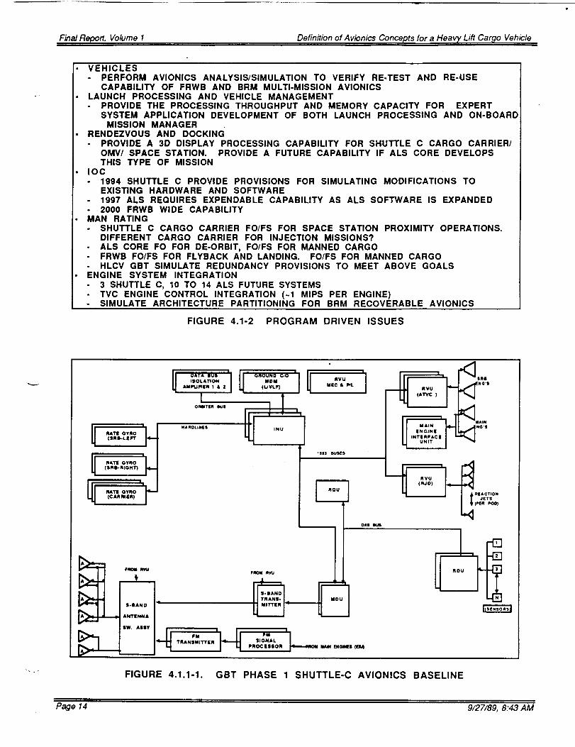
The HLCV expendable booster, (SDV-2ES), Shuttle-C, and Space Transfer Vehicledevelopmental programs are the basis for the Phase 1 GBT functional requirements. As wasshown in Figure 1.2-2, the Initial Operational Capability, (IOC), of the GBT is currently set forAugust 1990. The Shuttle-C was agreed upon to serve as the forcing function for the Phase1 lab. The functional block diagram for this three-string avionics system is shown in Figure4.1.1 -1.
Vehicle
ReusabilitylOG
I=n_ines
ManHatin_
ReliabilityMax Mission
Shuttle C
SRB's1995
3 + 2 SRBTBD
Cargo carderProx OPS & De-orbit
6-1/2 hours plus
S.S ops
ALS Core
None1998
30.99981
Deorbit to ocean.
FO/FS Manned CarcjoCore de-orbit
ALS LRB
BRM1998
70.99995
Sub-orbital
FO/FS Manned Carc_oT+
FRWB
Full Reuse2002
6 +6A/BTBD
Return & LandingFO/FS Manned Cargo
Less than
DurationMission/Year
Number of Vehicles
IntegratedSystems
Launch Processin¢_P/L and Vehicle I/F's
Vehicle
ManagementRendezvous &
Dockin_
Data Flow
Processing
FewModerate
Separate LPS, GSEProd C/O
LPS
Shuttle Bay InterfaceCentral computers O.S
Command Uplink
OMV AssistedTBD
Faidy low rate
300 KOPS
T + 98 rain.
ManyMany
UNIS for IntegratedData
Expert System AppNone
162 seconds
ManyMany
UNIS
Expert S}/stems App.None
Mission manager Controlled fromExpert Systems Core
Its accompanying Design Reference Missions (DRMs), are shown in Figure 5.1.1-2 TheseDRMs must be considered when building the software environmental and vehicle models.
4.1.2 PHASE 2 (ALS CORE, ALS BOOSTER, SDV 2RS)
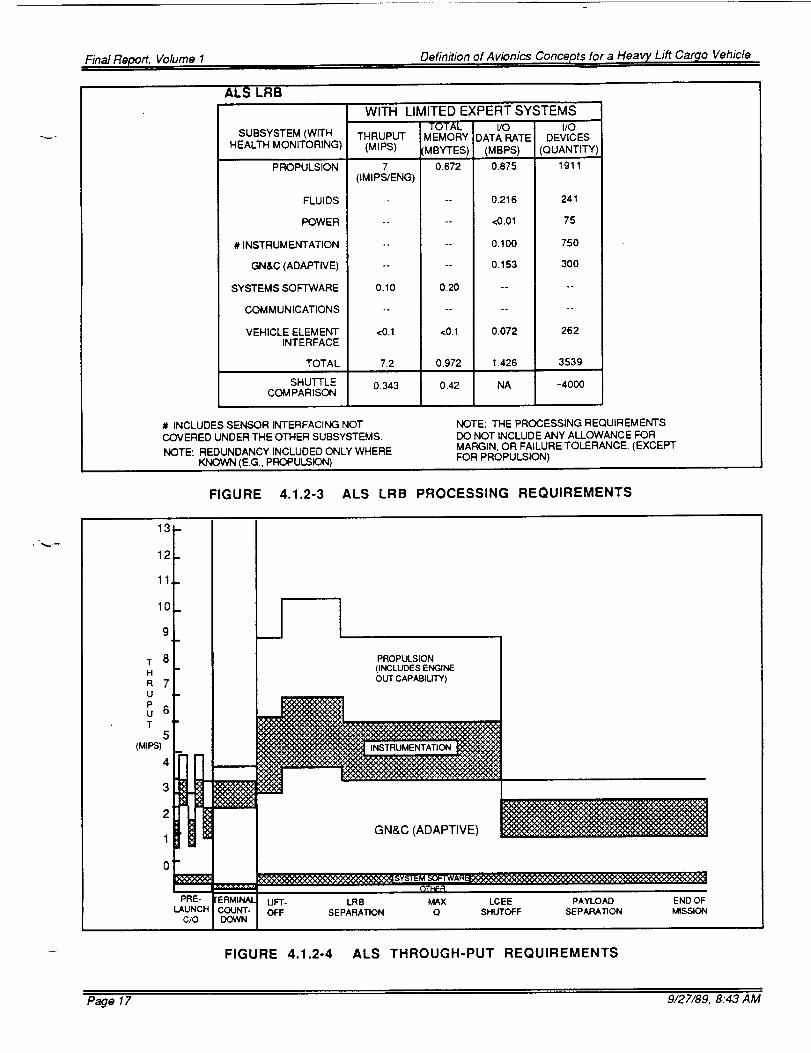
The Phase 2 IOC is set for August 1992. The Phase 2 GBT support capabilities will beextended to include the ALS Core and Booster, SDV-2RS, and the upgraded Shuttle-C.Since the ALS Core and Booster closely fit the SDV-2RS functional requirements, they werechosen for the reference vehicles for the Phase 2 GBT. Figure 4.1.2-1 through 4.1.2-3 show
the ALS Core and Booster avionics systems and the associated vehicle processingrequirements. Figure 4.1.2-4 associates the ALS Core throughput requirements with itsdesign reference mission timeline.
Page 13 9/27/89, 8:43 AM
Final Report, Volume 1 Definition of Avionics Concepts for a Heavy Lift Cargo Vehicle
• VEHICLES- PERFORM AVIONICS ANALYSIS/SIMULATION TO VERIFY RE-TEST AND RE-USE
CAPABILITY OF FRWB AND BRM MULTI-MISSION AVIONICS• LAUNCH PROCESSING AND VEHICLE MANAGEMENT
PROVIDE THE PROCESSING THROUGHPUT AND MEMORY CAPACITY FOR EXPERTSYSTEM APPLICATION DEVELOPMENT OF BOTH LAUNCH PROCESSING AND ON-BOARD
MISSION MANAGER• RENDEZVOUS AND DOCKING
PROVIDE A 3D DISPLAY PROCESSING CAPABILITY FOR SHUTTLE C CARGO CARRIER/OMV/ SPACE STATION. PROVIDE A FUTURE CAPABILITY IF ALS CORE DEVELOPSTHIS TYPE OF MISSION
• IOC1994 SHUTTLE C PROVIDE PROVISIONS FOR SIMULATING MODIFICATIONS TOEXISTING HARDWARE AND SOFTWARE1997 ALE REQUIRES EXPENDABLE CAPABILITY AS ALS SOFTWARE IS EXPANDED2000 FRWB WIDE CAPABILITY
MAN RATINGSHUTTLE C CARGO CARRIER FO/FS FOR SPACE STATION PROXIMITY OPERATIONS.DIFFERENT CARGO CARRIER FOR INJECTION MISSIONS?ALS CORE FO FOR DE-ORBIT, FO/FS FOR MANNED CARGOFRWB FO/FS FOR FLYBACK AND LANDING. FO/FS FOR MANNED CARGOHLCV GBT SIMULATE REDUNDANCY PROVISIONS TO MEET ABOVE GOALS
ENGINE SYSTEM INTEGRATION3 SHUTTLE C, 10 TO 14 ALE FUTURE SYSTEMSTVC ENGINE CONTROL INTEGRATION (-1 MIPS PER ENGINE)SIMULATE ARCHITECTURE PARTITIONING FOR BRM RECOVERABLE AVIONICS
INSERTION DIRECT STANDARD SUBORBITAL UPSPECIFIED UNSPECIFIED
FIGURE 4.1.1-2. SHUTTLE C MISSION REFERENCES
Page 15 9/27/89, 8:43 AM
Final Report, Volume 1 Definition of Avionics Concepts for a Heavy Lift Car_o Vehicle
AVIONICS DETAILED
TERTANK
OAPTER
1"O CORE .PWR BUS
ENGiNE CONT I
BOOSTER
RECOVERY
MOOULE
[_ TO CORE
INSTR BUS
BLOCK DIAGRAMFORWARD ADAPTER
SHRCUO
IN._ TRUkENI A_ON
/,\
--r-I
I
I
I
I
@I
I
I
_ R.. IGHT TE RMINAT___._.--
/ o__._ I _,_Tw. _vc.,L_ u_T _uAFT ENO | LA54ER FIRING UNIY LPU
i po,w._cc_mo,u.rr muPRODS4"t LFU I _ Ij=_,o_Eo,r, u_ mu
RAI1E GYRO LINFr RGU
AGE LCC REMOTE VOTER UNIT
TELEMETRY IfTERFACE U_T nu
THRUST VECTOR CC_ nqOL T_C
FIGURE 4.1.2-1 ALS AVIONICS & POWER SYSTEMS
ALS CORE
WITH LIMITED EXPERT SYSTEMS
SUBSYSTEM (WITHHEALTH MONITORING)
PROPULSION
FLUIDS
POWER
# INSTRUMENTATION
GN&C (ADAPTIVE)
SYSTEMS SOFTWARE
COMMUNICATIONS
VEHICLE ELEMENTINTERFACE
TOTAL 10.47
SHUFFLE 0.343COMPARISON
TOTAL I/OTHRUPUT MEMORY DATA RATE
(MIPS) ,MBYTES )
3 0.288(IMIPS/ENG
<0.1 <0.1
<0.1 <0.1
<3 <0.002
4.063 0.988
0.21 0.59
<0.1 <0.1
<0.1 <0.1
2.06
0.42
I/ODEVICES
(MBPS) (QUANTITY
0.375 819
0.216 241
<0.01 100
0256 1500
0.153 600
<0.01 100
0.072 262
1.09 3622
NA -4000
• ,;. ".}
# INCLUDES SENSOR PROCESSING NOTCOVERED UNDER THE OTHER SUBSYSTEMS.
NOTE: REDUNDANCY INCLUDED ONLY WHEREKNOWN (E.G., PROPULSION)
NOTE: THE PROCESSING REQUIREMENTSDO NOT INCLUDE ANY ALLOWANCE FORMARGIN, OR FAILURE TOLERANCE. (EXCEPTFOR PROPULSION)
FIGURE 4.1.2-2 ALS CORE PROCESSING REQUIREMENTS
Page 16 9/27/89, 8:43 AM
Final Report, Volume 1 Definition of Avionics Concepts for a Heav 7 Lift Car_to Vehicle
ALS LRB
SUBSYSTEM (WITHHEALTH MONITORING)
PROPULSION
FLUIDS
POWER
# INSTRUMENTATION
GN&C (ADAPTIV E)
SYSTEMS SOFTWARE
COMMUNICATIONS
VEHICLE ELEMENTINTERFACE
TOTAL
WITH LIMITED EXPERT SYSTEMSTOTAL VO I/O
THRUPUT i MEMORY DATA RATE DEVICES(MIPS) (MBPS) (QUANTITY)
7(IMIPS/ENG)
-o
.o
o.
oo
0.10
°.
<0.1
7.2
SHUTTLE 0.343COMPARISON
MBYTES)
0.672
o.
0.20
<0.1
0.972
0.42
0.875 1911
0.216 241
<0.01 75
0.100 750
0.153 300
0.072 262
1.426 3539
NA ~4000
# INCLUDES SENSOR INTERFACING NOTCOVERED UNDER THE OTHER SUBSYSTEMS.
NOTE: REDUNDANCY INCLUDED ONLY WHEREKNOWN (E.G., PROPULSION)
NOTE: THE PROCESSING REQUIREMENTSDO NOT INCLUDE ANY ALLOWANCE FORMARGIN, OR FAILURE TOLERANCE. (EXCEPTFOR PROPULSION)
FIGURE 4.1.2-3 ALS LRB PROCESSING REQUIREMENTS
13
12
11
lO
T 8H
R 7U
Pu 6T
5(MIPS)
4
3
PROPULSION
(INCLUDES ENGINE
OUT CAPABIUTY)
INSTRUMENTATION
GN&C (ADAPTIVE)
PRE- UFT- LR8 MAX LCEE PAYLOAD
LAUNCH COUNT- OFF SEPARATION Q SHUTOFF SEPARATIONC/O DOWN
FIGURE 4.1.2-4 ALS THROUGH-PUT REQUIREMENTS
END OF
MISSION
Page 17 9/27/89, 8:43 AM
Final Report, Volume 1 Definition of Avionics Concepts for a Heavy Lift Cargo Vehicle
4.1.3 Target (FRWB, FRWB, PRCV)
The Phase 3 or Target configuration IOC has not been set, but if it is tied to the FullyRecoverable Wing Booster (FRWB), and the Partially Reusable Cargo Vehicle (PRCV)programs, it should be in 1996 to 1998.
Figure 4.1.3-1 outlines the Processing Requirements for the FRWB while Figure 4.1.3-2associates the throughput requirements with the FRWB mission timeline. The FRWB avionicssystem is designed to be fully autonomous from launch to landing and roll out. The GBTscapability to support FRWB and PRCV development must start long before the 1996-1998IOC. The GBT functions must include FRWB/PRCV related inputs in both Phase 1 and Phase2. Typical of these inputs are:
(1) Electromechanical Actuator applications in vehicle aero control and Thrust VectorControl systems;
(2) Redundancy Management using Expert Systems and a distributed processing system;and
(3) An autonomous, robust GN&C system capable of near all-weather launches andminimum tailoring of software mission to mission.
These technology driven requirements are discussed in the next section.
FULLY REUSABLE WINGED BOOSTER (FRWB)
SUBSYSTEM (WITH
HEALTH MONITORING)
"PROPULSION
FLUIDS
POWER
# INSTRUMENTATION
GN&C (ADAPTIVE)
SYSTEMS SOFTWARE
COMMUNICATIONS
VEHICLE ELEMENTINTERFACE
TOTAL
SHUTTLE
COMPARISON
PROCESSING IS TIME SHAREDBETWEEN BOOSTER ENGINESAND AIR BREATING ENGINES.
# INCLUDES SENSOR PROCESSINGNOT COVERED UNDER OTHERSUBSYSTEMS.
NOTE: REDUNDANCY INCLUDED ONLYWHERE KNOWN (E.G., PROPULSION).
WITH LIMITED EXPERT SYSTEMS
TOTAL I/O I/OTHRUPUT MEMORY DATA RATE DEVICES
(MIPS) 'MBYTES) ! (MBPS) (QUANTITY)
1 152 06 3264
(IMIPS/ENG)
<0.1 <0.1 0.32 380
<0 1 <0.1 <0.01 180
<3 0.0048 0.320 4000
5.199 1264 0.394 1225
0.24 0.79 ....
<0.1 <0.1 <0.01 120
<O.1 <0.1 0.0256 5
14.64 3.42 1.67 91 74
0.343 0.42 NA -4000
NOTE: THE PROCESSING REQUIREMENTSDO NOT INCLUDE ANY ALLOWANCE FOR
MARGIN, OR FAILURE TOLERANCE {EXCEPTFOR PROPULSION).
NOTE: THE PROCESSING REQUIREMENTS DONOT INCLUDE THE IMAGING SENSORPECULIAR PROCESSING WHICH ISASSUMED TO BE SELF CONTAINED.
FIGURE 4.1.3-1. FRWB PROCESSING REQUIREMENTS
Page 18 9/27/89, 8:43 AM
Final Report, Volume I Definition of Avionics Concepts for a Heavy Lift Cargo Vehicle
13
12
11
1C
T 9H
R 8UPu 7T
(MIPS) 6
5
4
i20 _
IPRE-
lAUNCHCIO
i"ERMINALCOUNT-
DOWN
rINCLUDES HEALTH MONITORING. |INCLUDES REDUNDANCY WHERE KNOWN• LNO MARGIN ALLOWANCE.
PROPULSION
_,J_ | (INCLUOES ENGINE
B
GN&C (AOAPTWE)
Q'_IFRLIFT- MAX LRB FRWB FBE MSBLS TOUCH- ROLL- END uFOFF Q SEPARATION RE-ENTRY IGNITION ACQUISITION DOWN OUT MISSION
FIGURE 4.1.3-2. FRWB THROUGH-PUT REQUIREMENTS
4.2 TECHNOLOGY DRIVEN REQUIREMENTS
Several pacing technologies were investigated during the initial stages of this study. Eachwas associated with their specific application on the HLCV era avionics systems andprioritized as to their role in achieving the design goals. The following paragraphs show theimpact on the GBT design.
4.2.1 SYSTEM ARCHITECTURES/REDUNDANCY MANAGEMENT
One of the most fundamental drivers of the GBT processing/throughput requirements involvesthe basic vehicle architectures to be simulated and the operational environment in which theymust be tested. The basic Phase 1 through the complex Target GBT configuration had to besized to full-up, end-to-end, real-time vehicle system simulations. This translates into athroughput requirement for the lab of about 150 million instructions per second (MIPS) for thePhase 2 GBT. The processor assigned to model the system architecture had to be able tomodel a parallel, distributed, multi-string system; duplicate the redundancy managementlogic of that system and be able to monitor, control and provide external stimuli to the systemunder test. The FRWB avionics system is fully autonomous and, therefore, includesIntegrated Health Monitoring (IHM), and a high precision launch to launch GN&C system thatmay incorporate a multi-spectral Image Processing System. Much of the traditional GSEfunctions will be performed by the FRWB system. All these factors will drive the GBTthroughput and parallel processing capacity well beyond the 150 MIPS of the Phase 2 lab.This mandates a main processing capacity which can be expanded incrementally withouthaving to replace the original equipment.
Page 19 9/27/89, 8:43 AM
Final Report, Volume 1 Definition of Avionics Concepts for a Heavy Lift Car_o Vehicle
4.2.2 POWER DISTRIBUTION, CONDITIONING AND MANAGEMENT
The HLCV era vehicles are required to perform over a wide ranging series of missions thatlast from 90 minutes to several months. The reliability required of the supporting powersystems plus the new demands of cost effectiveness have driven a re-examination oftraditional solutions and a search for new designs. The increasing demand for power byelectromechanical actuators and the new designs being utilized in their attendant powersupplies have elevated this once stable design area into new activity. The GBT powerextension will be able to evaluate alternate power sources (batteries, fuel cells and solarcells), power distribution system architectures, redundancy management schemes, anddifferent methods of power conditioning and management.
4.2.3 ELECTRO MECHANICAL ACTUATORS
The clustered rocket engines of many of the HLCV vehicles have accelerated development offast response high power (> 50 hp) electromechanical actuators. The HLCV GBT will supportthis effort in Phase 2. Development will be in the power supply design as well as that of thebasic actuator.
The integration of actuator development and testing in the total vehicle development programinvolves several areas. The end-to-end testing would, in its highest fidelity mode, require theactuator under test to be dynamically loaded. This loading would be controlled in part byinputs from the missions environmental and vehicle dynamic models. The dynamic load celland its attendant support equipment could represent a prohibitively high investment. Use ofexisting or dedicated actuator labs may prove the most cost effective method of providing thisresource. A high data rate, broadband data link to the GBT could be used in closed looptesting. EMA power supply development could be accommodated in the GBT PowerSystems extension.
4.2.4 ADAPTIVE GUIDANCE, NAVIGATION & CONTROL
HLCV traffic models force a more robust launch capability. Not only do vehicles have to beeasy to process and launch, they must be strong enough and smart enough to handle lessfavorable environmental conditions. Supporting Adaptive Guidance, Navigation & Controlwould include everything from concept evaluation through sensor design testing. Primaryimpact of this technology support by the GBT would be in the area of software development,and attendant processor capacity and flexibility. Special software analysis tools will berequired in the investigation of various load relief concepts, sensor applications and vehicledynamic control modeling.
4.2.5 IMAGE PROCESSING
The application of image processing to HLCV functions seems particularly attractive in theareas of rendezvous & docking and approach & landing. The delays and subsequent risksinvolved in the remote docking techniques used in OMV can be potentially mitigated with a"smart" docking system. Such a system could be used on the STV or retrofitted on the OMV.Use of image processing to detect/identify the target, its range and orientation are well withincurrent state-of-the-art capabilities. Application in the FRWB approach & landing functions isanother application to be investigated.
Page 20 9/27/89, 8:43 AM
FinalReport, Volume 1 Definition of Avionics Concepts for a Heavy Lift Car_o Vehicle
Impact to the GBT design would include software tools required for high fidelity 3D Targetmodeling and animation. Hardware requirements would include prototype sensors, TVcamera, large, high resolution graphic monitor and an image processing workstation.
5.0 GBT IMPLEMENTATION PLANNING
From the beginning, it was recognized that the Ground Based Test beds capabilities wouldbe tied to meeting current program system testing requirements. The GBTs role was toencompass vehicle simulation and testing needs from inception to the Preliminary DesignReview (PDR). Looking at the projected vehicle developmental schedules, it was all too clearthat the first operational GBT capabilities would have to be focused on the criticaldevelopmental problems. If vehicles like the Shuttle C or STV were to be supported prior totheir PDRs the GBT must be at least operational by August 1990. Basic avionic systemarchitectural issues would have to be addressed first. The initial GBT would have to provide
high fidelity, precision guidance & navigation simulations that supported evaluation of theseveral configurations being investigated. This dictated identification of long lead items likethe 3-axis table.
Software model development is another key factor in the implementation plan. Fidelity of thevehicle dynamic and system models is critical to establishing the GBT as a valuable programdevelopment resource. This usually requires actual hardware being used to develop andverify the fidelity of the respective software models. Availability of similar hardware oftenproves to be another pacing element.
Accelerating the application of new, useful technologies into current and future programs wasanother stated goal of the GBT. To this point, all the GBT capabilities were directed atspecific problems of specific programs because of time related and money relatedconstraints. The implementation plan has evolved to the point that permits visibility as to howthis goal can be realized. First, the basic GBT hardware and software design is modular andthus can be changed easily to accommodate different requirements. The early phases ofimplementation require the building of a specific number of these basic modules to satisfy alimited number of needs. To satisfy a greater set of requirements relatively few new modulesare required.
Figure 5.0-1 shows an early implementation schedule and its assumptions. One of the mostdifficult problems of the implementation schedule, shown earlier in figure 1.2-2, is the amountof work to be done in the first phase. Between February 1989 and August 1990, over 60% ofthe total task must be accomplished. This is not consist with the relatively low front endfunding guidelines that were provided for this study. Figure 5.0-2 shows this problemgraphically.
The bottom line for GBT success is being able to supply the most cost effective and useful testfacility at the time when new programs need it the most. This implies that the projects arewilling to pay their way and plan for such usage initially. This idealistic form of funding mustbe recognized as supplemental to basic level of funding needed to initially implement andlater maintain GBT operations. Internal Research & Development projects are also a sourceof funding. This type of function typically accelerates the application of useful, newtechnologies and test concepts upon which later major programs are built.
Page 21 9/27/89, 8:43 AM
Final Report, Volume I Definition of Avionics Concepts for a Heavy Lift Cargo Vehicle
LAB PRELIMINARY IMPLEMENTATION SCHEDULE
lg89 lg90 1991 1992 1993 1994 199. =
HLCV Related Milestones• SOV-2ES IOC 1993•SDV-2RS IOC 1995
•FRWB IOC 1998.2000+
•PRCV IOC 1998-2000+
SHUTTLE C IOC 1994
ALS IOC 1996-98
Upper Stages•OTV IOC TBO
•AOTV IOC TBD
INITIAL Lab MllaSIonea
-Procurement
• S/W Devolopmont
•H/W Design & Fob
• Fit H/W Acq
•Facility Prop*Lob Activation
RFP |tart PD COR PF On Pad
ALS P Ion 3A s,ort
_IL LAI lOC
mi_Evolutlon or 0ol nstreo IOC
Lab Program Drivers
4 Year Development Cycle
• IOC First Launch. Delivery to pad 1 year prior to Launch.
Full Scale Engineering Development Systems Integration Laboratory with Pathfinder Activity
• APC Supports Early PDRs
FIGURE 5.0-1. IMPLEMENTATION PLAN
IMPLEMENTATION ISSUES
1989 1990 1991 1992 1993
J
J r_
_S _ v
._.Y fJ
jm,_v jv
Jl_ J m"J ""
/
• y
v
f
j_
I
01 IOC
ISSUES• SOFTWARE DEVELOPMENT TIME
- 70% of Target SAN needed by Aug 1990• HARDWARE ACQUISITION
- 3 Axis Table requires I Year lead time• FACILITY
- Site modifica_ons not completed for • 1
02 IOC
1994
_v
TARGETIOC
LEG END
Projected FundingCurrent Requirements
FIGURE 5.0-2 IMPLEMENTATION ISSUES
6.0 GBT ARCHITECTURE
Page 22 9/27/89, 8:43 AM
Final Report, Volume I Definition of Avionics Concepts for a Heavy Lift Cargo Vehicle
This section covers both the hardware and software architectures of the GBT. It should benoted that the GBT has been structured to allow for a phased implementation of capabilities.
The Target GBT is the full-up, third step configuration. It was designed to support the thirdHLCV reference configuration. This Fly Back Booster and Partially Reusable Cargo Vehicle
must be accommodated in the Target GBT end-to-end real-time simulation.
6.1 HARDWARE CONFIGURATIONS
6.1.1 GBT TARGET CONFIGURATION
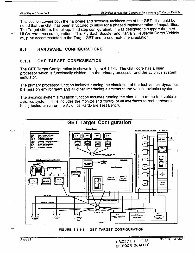
The GBT Target Configuration is shown in figure 6.1.1-1. The GBT core has a mainprocessor which is functionally divided into the primary processor and the avionics systemsimulator.
The primary processor function includes running the simulation of the test vehicle dynamics,the mission environment and all other interfacing elements to the vehicle avionics system.
The avionics system simulation function includes running the simulation of the test vehicleavionics system. This includes the monitor and control of all interfaces to real hardwarebeing tested or run on the Avionics Hardware Test Bench.
GBT Target Configuration
m
m
m
i
_ •
I
I QOT
1
FIGURE 6.1.1-1. GBT TARGET CONFIGURATION
Page 23
OF POOR QiDALfI'Y
9127/89, 8:43 AM
FinalReport, VolumeI Definition of Avionics Concepts for a Heavy Lift Car,_o Vehicle
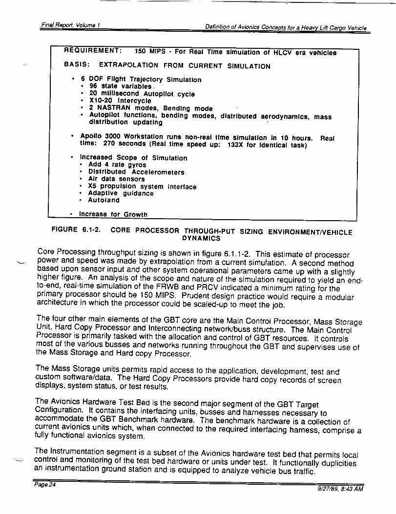
REQUIREMENT: 150 MIPS - For Real Time simulation of HLCV era vehicles
• Apollo 3000 Workstation runs non-real time simulation In 10 hours. Realtime: 270 seconds (Real time speed up: 133X for Identical task)
Increased Scope of Simulation• Add 4 rate gyros• Distributed Accelerometers• Air data sensors• X5 propulsion system interface• Adaptive guidance• Autoland
Core Processing throughput sizing is shown in figure 6.1.1-2. This estimate of processorpower and speed was made by extrapolation from a current simulation. A second methodbased upon sensor input and other system operational parameters came up with a slightlyhigher figure. An analysis of the scope and nature of the simulation required to yield an end-to-end, real-time simulation of the FRWB and PRCV indicated a minimum rating for theprimary processor should be 150 MIPS. Prudent design practice would require a modulararchitecture in which the processor could be scaled-up to meet the job.
The four other main elements of the GBT core are the Main Control Processor, Mass StorageUnit, Hard Copy Processor and Interconnecting network/buss structure. The Main ControlProcessor is primarily tasked with the allocation and control of GBT resources. It controlsmost of the various busses and networks running throughout the GBT and supervises use ofthe Mass Storage and Hard copy Processor.
The Mass Storage units permits rapid access to the application, development, test andcustom software/data. The Hard Copy Processors provide hard copy records of screendisplays, system status, or test results.
The Avionics Hardware Test Bed is the second major segment of the GBT TargetConfiguration. It contains the interfacing units, busses and harnesses necessary toaccommodate the GBT Benchmark hardware. The benchmark hardware is a collection ofcurrent avionics units which, when connected to the required interfacing harness, comprise afully functional avionics system.
The Instrumentation segment is a subset of the Avionics hardware test bed that permits localcontrol and monitoring of the test bed hardware or units under test. It functionally duplicitiesan instrumentation ground station and is equipped to analyze vehicle bus traffic.
Page 24 9/27/89, 8:43 AM
Final Report, Volume 1 Definition of Avionics Concepts for a Heavy Lift Car_lo Vehicle
The GBT Display Center electronic equipment is shown in part in figure 6.1.1-1. it primarilyconsists of four graphics processors driving four large screen monitors. The graphicsprocessors are used to develop display and other support type graphics. Working with thelarge screen monitors, the processors can reproduce demonstration graphics depictinganything from real-time test parameters to reproduction of demonstration graphics. Thesemonitors may be used to supplement the status displays available to the core's main controlprocessor. The graphics processors will also supplement the Main Control Processor incontrolling parallel operations going on within the GBT.
The G&N Lab is one of the most important resources available to the GBT. Though capableof fully independent operation, in an acceptance test procedure role, its primary value is inclosed-loop simulation of an integrated avionics system. The precision 3-axis table cansupply all necessary stimuli, except acceleration, to evaluate the best inertial elements of theHLCV era. The Slave I/O interface box will provide the local real-time interfaces toaccommodate such testing.
6.1.2 PHASE 1 CONFIGURATION
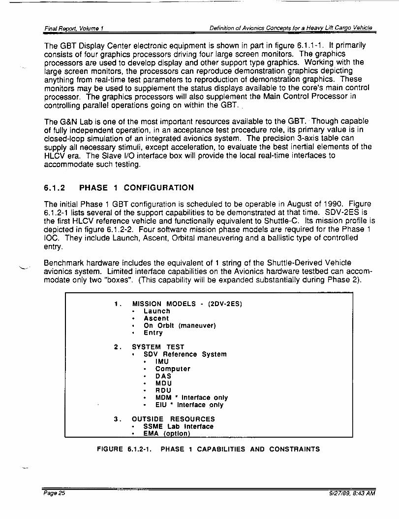
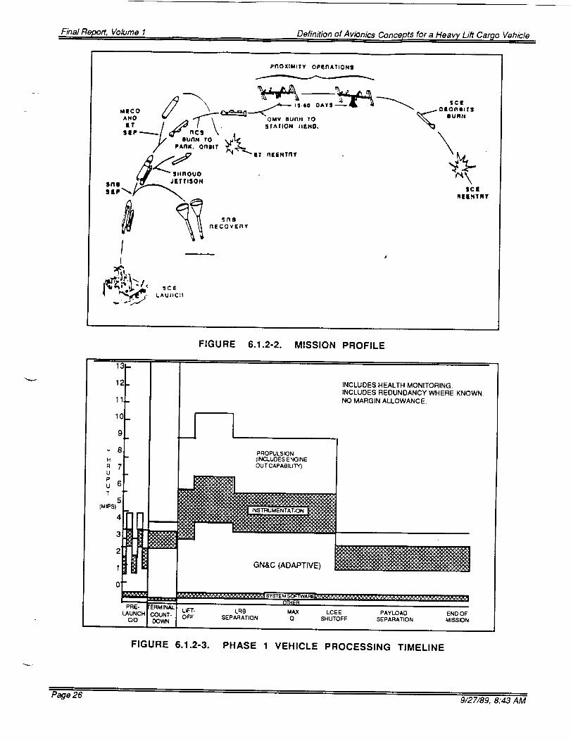
The initial Phase 1 GBT configuration is scheduled to be operable in August of 1990. Figure6.1.2-1 lists several of the support capabilities to be demonstrated at that time. SDV-2ES isthe first HLCV reference vehicle and functionally equivalent to Shuttle-C. Its mission profile isdepicted in figure 6.1.2-2. Four software mission phase models are required for the Phase 1IOC. They include Launch, Ascent, Orbital maneuvering and a ballistic type of controlledentry.
Benchmark hardware includes the equivalent of 1 string of the Shuttle-Derived Vehicleavionics system. Limited interface capabilities on the Avionics hardware testbed can accom-modate only two "boxes". (This capability will be expanded substantially during Phase 2).
• MISSION MODELS (2DV-2ES)• Launch• Ascent• On Orbit (maneuver)• Entry
. SYSTEM TEST• SDV Reference
• IMU• Computer• DAS• MDU• RDU
System
MDM * Interface onlyEIU * Interface only
. OUTSIDE RESOURCES• SSME Lab Interface• EMA (option)
FIGURE 6.1.2-1. PHASE 1 CAPABILITIES AND CONSTRAINTS
Page 25 9/27/89, 8:43 AM
Final Report, Volume I Definition of Avionics Concepts for a Heavy Lift Car_lo Vehicle
I
PROXIMITY OPU"IATIO NS
.,-
$clRllENTRY
sng
nECOVERY
FIGURE 6.1.2-2. MISSION PROFILE
i,
13-
12.
11r
I0
g
T 8H
R 7U
P
u 6T
5(MIPS)
4
PROPULSION
(INCLUDES ENGINE
OUT CAPABILITY)
m
i ii=GN&C (ADAPTIVE)
INCLUDES HEALTH MONITORING.INCLUDES REDUNDANCY WHERE KNOWN.NO MARGIN ALLOWANCE.
0' m
..r..a=M.a,._w ,Q"I_:R
PRE- FERMINAL LIF",F- LRe, MAX LCEE PAYLOAO END OF
LAUNCH COUNT- OFF SEPARATION Q SHUTOFF SEPARATION MISSION
Final Report, Volume I Definition of AvionicsConcepts for a Heavy Lift Car_lo Vehicle
Figure 6.1.2-3 shows a vehicle processing throughput as a function of time. These projectedthrough-put levels added to the requirements for vehicle dynamics and mission environmentrequire the core processor to equal or exceed its projected 70+ MIPS configuration for Phase1.
Flight operations for Shuttle-C, shown in figure 6.1.2-4 were used in projecting thethroughput requirements.
The Phase 1 GBT Configuration is pictured in figure 6.1.2-5. Many target capabilities areabsent. Among these are the interface provisions to many of the resource labs andextensions. The G&N Lab is the exception where a full link is present. The Propulsion Labalso will have a port available on the fiber optic communications and control bus.
AUTONOMOUS FLIGHT CONTROL TO ORBITAL INSERTION, CIRCULIZATION
AND DEORBIT
• Simplex Shuttle-C mission control center
• Basic Shuttle-C avionics for this function
• Precursor mission planning (simplex), payload Integration to cargo bay by
Shuttle-C
ORBITAL DEPLOY MISSIONS (E.G., PLANETARY AND OTHER FREE FLYING
SPACECRAFT
• Payload developer responsible for operations from POCC after payload
separation
SPACE STATION MISSIONS
Prect_'sor mission (4 on orbit) planning done as part of OMV/SS activity
OMV/Space Station control center responsible for rendezvous, Prox-ops,
docking, mission operations (e.g., assembly) and deorbit from SS/OMV
control center or multi-purpose control center
Very limited °'kit on" Shuttle-C delta avionics including batteries_ etc.
FIGURE 6.1.2-4. FLIGHT OPERATIONS
The GBT Core Processor is only partially filled, giving it a throughput of about 70+ MIPS. Thesoftware will be developed initially on the Graphic Processors residing in the display center.The function of the display/demo center and software development will be performed at thatlocation. The benchmark hardware used in the avionics hardware testbed will probably be asingle string of the Shuttle-C architecture. The interfacing capabilities of the Master I/O unitwill accommodate only the equivalent of an Inertial Navigation Unit (INU) and a RemoteVoting Unit (RVU) simultaneously.
Page 27 9/27/89, 8:43 AM
Final Report, Volume I Definition of Avionics Concepts for a Heavy Lift Car_o Vehicle
GBT PHASE 1 CONFIGURATION
FIGURE 6.1.2-5 GBT PHASE 1 CONFIGURATION
6.1.3 PHASE 2 CONFIGURATION
The Phase 2 GBT capabilities and constraints are listed in figure 6.1.3-1. Vehicle simulationcapabilities now include the ALS Booster and Core. The overall simulation capability is moregeneric than before, with the complete range of software modules completed. The CoreProcessor has been fully expanded to the target configuration, permitting complete end-to-end, real-time simulations. Rendezvous and Docking and Precision Entry simulations willalso be possible in Phase 2.
Hardware testing of a complete "string" of avionics equipment will be possible with theavionics hardware test bench. A more complete set of generic software models will beavailable for use.
Figure 6.1.3-2 depicts the Phase 2 GBT configuration. Note the changes in the hardware testbed and display center. Now a separate software development facility is available and linksare available to a variety of labs and extensions.
Page 28 9/27/89, 8:43 AM
Final Report, Volume 1 Definition of Avionics Concepts for a Heavy Lift Car_lo Vehicle
Final Report, Volume 1 Definition of Avionics Concepts for a Heavy Lift Cargo Vehicle
7.0 HLCV GROUND BASED TESTBED FACILITIES
The detailed facility requirements for each major GBT element are contained in thePreliminary Design Document, (PDD). These requirements cover the basic power, spaceand environmental needs of the major GBT elements but don't address the overall Lablayout. This section will summarize the recommendations from which the layout will bedetermined. Fuller definition of the layout was deferred pending definition of the actual GBTsite and the modification possible with the funds allotted.
7.1 LOCATION
Key to the utility of the Ground Based Testbed is its proximity to the resources itmust draw upon and serve. Early utilization will be enhanced if it is close to exhaustingtesting facilities. As the GBT primary processor and attendant communication networks arebrought onto line, closed loop simulations, involving one or more adjacent labs will become
possible. Early attention to those existing laboratory resources that would most befit from theadded GBT capabilities should be a factor in selecting the GBT location.
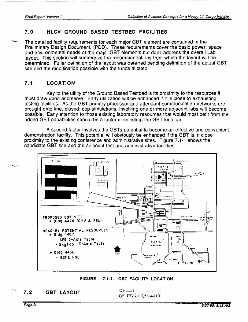
A second factor involves the GBTs potential to become an effective and convenientdemonstration facility. This potential will obviously be enhanced if the GBT is in closeproximity to the existing conference and administrative sites. Figure 7.1-1 shows thecandidate GBT site and the adjacent test and administrative facilities.
FIGURE 7.1-1. GBT FACILITY LOCATION
7.2 GBT LAYOUTOF PCO;':_ Q,J,,;_,L;'_-',f
Page 30 9/27/89, 8:43 AM
Final Report, Volume I Definition of Avionics Concepts for a Heavy Lift Cargo Vehicle
Figure 7.2-1 shows the basic Building 4476 1st floor plan. The area designated for the GBTis shown in figure 7.2-2.
I I
I103
OaltewyRoam
106
M,ed'_n_ F.qz.M_m_,Z
102 120¢
Im
IIg11761 _ 114
Eleclrtcal Equi_ent
llS
C o_ S'ol Room
L 113 vlbraoon 7q_i_ent
i - F ,., r,,,---1,,,260+ 0"_
T60' O"
LF
11, 96' 0"
i--
FIGURE 7.2-1. BUILDING 4476, MSFC, FIRST FLOOR
.J
102
Mens
Room
120b
1 20 120a
70' 0"
120c
1
50' O"
60' O"
119
_112
G
I118
I.
113
FIGURE 7.2-2. DESIGNATED GBT AREA, MSFC BUILDING 4476, FIRST FLOOR
A change to this area is already in work, but the completion dates do not support the currentPhase 1 IOC date of August 1990. This proposed change has three options. The "A" optionwas used in this study.
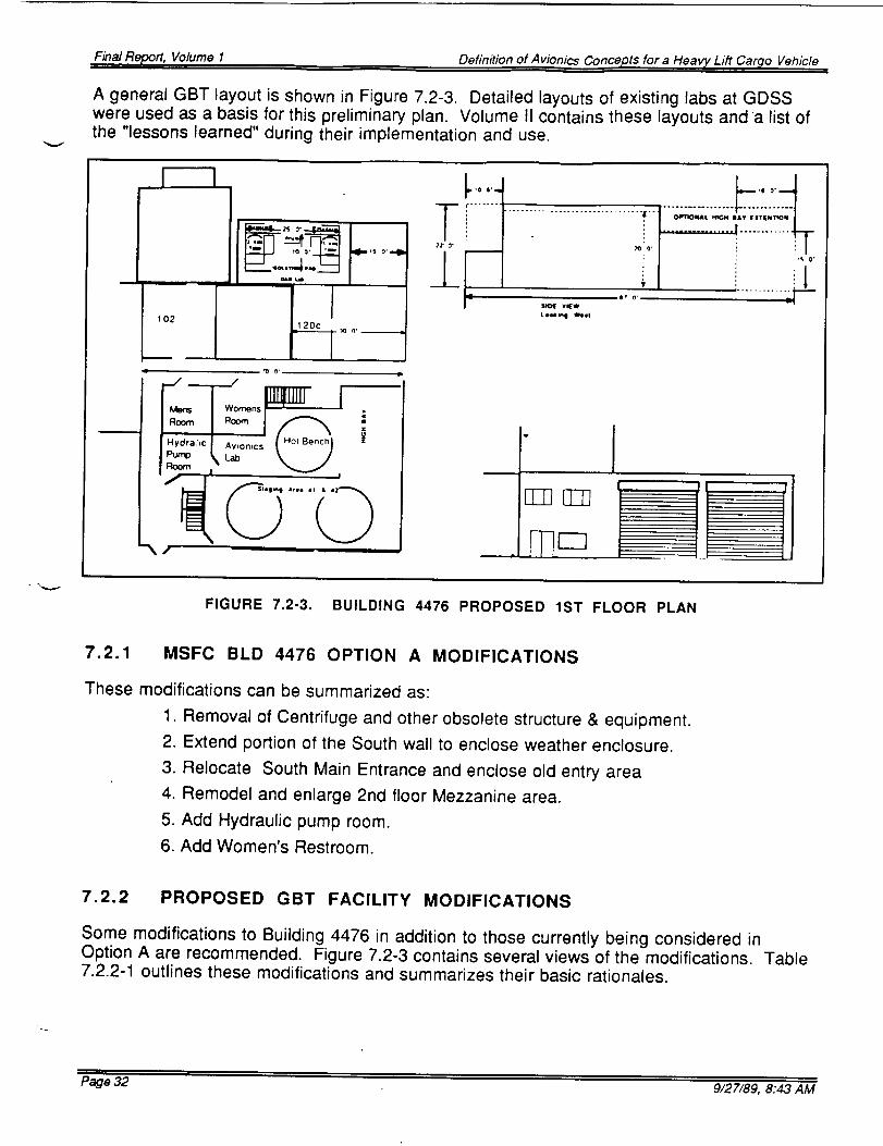
A general GBT layout is shown in Figure 7.2-3. Detailed layouts of existing labs at GDSSwere used as a basis for this preliminary plan. Volume II contains these layouts and a list ofthe "lessons learned" during their implementation and use.
FIGURE 7.2-3. BUILDING 4476 PROPOSED 1ST FLOOR PLAN
7.2.1 MSFC BLD 4476 OPTION A MODIFICATIONS
These modifications can be summarized as:
1. Removal of Centrifuge and other obsolete structure & equipment.
2. Extend portion of the South wall to enclose weather enclosure.
3. Relocate South Main Entrance and enclose old entry area
4. Remodel and enlarge 2nd floor Mezzanine area.
5. Add Hydraulic pump room.
6. Add Women's Restroom.
7.2.2 PROPOSED GBT FACILITY MODIFICATIONS
Some modifications to Building 4476 in addition to those currently being considered inOption A are recommended. Figure 7.2-3 contains several views of the modifications. Table7.2.2-1 outlines these modifications and summarizes their basic rationales.
Page 32 9/27/89, 8:43 AM
Final Report,Volume I Definition of Avionics Conceptsfor a Heavy Lift Cargo Vehicle
TABLE 7.2.2-I
N O DESCRIPTION
1 Southern High Bay Extensionwith 2 large access doors.
2. Northern G&N Lab Extension
3. Northern High Bay Extension
4. Mezzanine Modification
RATIONALE
1. Provides access to High Bay andstaging areas #1 & #2.
2. Accommodates G&N labs & providesNorth Star LOS. Provides easiestmethod to provide Isolation pads for3 axis table.
3. Accommodates future "flow through"processing of modules & staging.
, Optimizes main processor areas toresources (shortens distance to HotBench & staging areas by placing mainprocessor on mezzanine.
7.2.3 PROPOSED GBT SPACE ALLOCATION
The original Target GBT floor plan approached 10000 square feet and featured a two storylayout. The candidate site offered about one third of the space unmodified. Optional add-onsbring the usable space to around 5000 square feet and optimizes the usefulness of the 2ndfloor area.
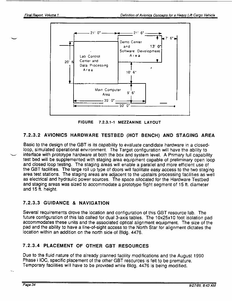
7.2.3.1 DEMONSTRATION, CONTROL & PROCESSING CENTERS
Figure 7.2.3.1-1 shows a general spatial allocation of the mezzanine. The GBT PrimaryProcessor, Control Processor, Mass memory and hard copy printing devices will be housedin the GBT Processing Center upstairs and adjacent to the Demonstration & Control Center.Both areas will have independently controllable environments designed to properlyaccommodate the data processing equipment, staff and visitors. Attention will be given toprovide a view of high bay and staging area operations. Windowed partitions will be utilizedto provide the designed view of the Processing Center and downstairs working areas whilemaintaining the controlled equipment. The Demonstration area will accommodate up to 20visitors in a design which permits a good view of the large screen monitors, projectionscreens and main control console. Individual control of the Demonstration Centertemperature and lighting is imperative.
Safety provisions for rapid egress from the mezzanine require two stairways. Provisions toprotect the Primary Processing Center from fire and intrusion should be provided. A Halonsystem should be investigated.
Page 33 9/27/89, 8:43 AM
Final Report, Volume I Definition of Avionics Concepts for a Heav 7 Lift Car_lo Vehicle
21' 0" _= 21' 6"!
Demo Center Iq7'
/
and 13' 0"[
Software Development/
Area l
. ?/
l ,10'6"
Main Computer I !9' 6" /Area
4/
35' 0" .L
,i 50" o" D
Lab Control
Center and
Data ProcessingArea
6"lP
FIGURE 7.2.3.1-1 MEZZANINE LAYOUT
7.2.3.2 AVIONICS HARDWARE TESTBED (HOT BENCH) AND STAGING AREA
Basic to the design of the GBT is its capability to evaluate candidate hardware in a closed-loop, simulated operational environment. The Target configuration will have the ability tointerface with prototype hardware at both the box and system level. A Primary full capabilitytest bed will be supplemented with staging area equipment capable of preliminary open loopand closed loop testing. The staging areas will enable a parallel and more efficient use ofthe GBT facilities. The large roll up type of doors will facilitate easy access to the two stagingarea test stations. The staging areas are adjacent to the upstairs processing facilities as wellas electrical and hydraulic power sources. The space allocated for the Hardware Testbedand staging areas was sized to accommodate a prototype flight segment of 15 ft. diameterand 15 ft. height.
7.2.3.3 GUIDANCE & NAVIGATION
Several requirements drove the location and configuration of this GBT resource lab. Thefuture configuration of this lab called for dual 3-axis tables. The 10x25x10 foot isolation padaccommodates these units and the associated optical alignment equipment. The size of thepad and the ability to have a line-of-sight access to the North Star for alignment dictates thelocation within an addition on the north side of Bldg. 4476.
7.2.3.4 PLACEMENT OF OTHER GBT RESOURCES
Due to the fluid nature of the already planned facility modifications and the August 1990Phase i IOC, specific placement of the other GBT resources is felt to be premature.Temporary facilities will have to be provided while Bldg. 4476 is being modified.
Page 34 9/27/89, 8:43 AM
Final Report, Volume 1 Definition of Avionics Concepts for a Heavy Lift Car_lo Vehicle
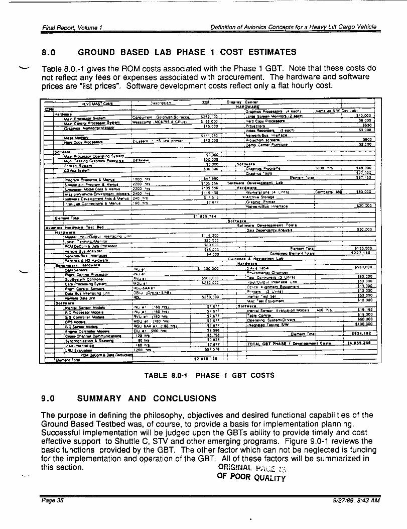
8.0 GROUND BASED LAB PHASE 1 COST ESTIMATES
Table 8.0.-1 gives the ROM costs associated with the Phase 1 GBT. Note that these costs donot reflect any fees or expenses associated with procurement. The hardware and software
prices are "list prices". Softwaredevelopment costs reflect only a flat hourly cost.
_.oltwlro Development Tool11
H 11r|lY 11re
twor_u 11 rnlStf ices 4-
i'ia_]wat11
lenchmltll M11rdwere ._
TABLE 8.0-1 PHASE 1 GBT COSTS
9.0 SUMMARY AND CONCLUSIONS
The purpose in defining the philosophy, objectives and desired functional capabilities of the
Ground Based Testbed was, of course, to provide a basis for implementation planning.Successful implementation will be judged upon the GBTs ability to provide timely and costeffective support to Shuttle C, STV and other emerging programs. Figure 9.0-1 reviews the
basic functions provided by the GBT. The other factor which can not be neglected is fundingfor the implementation and operation of the GBT. All of these factors will be summarized in
this section. OR[G_NP, L P;_-:._2__:::
OF POOR QUALITY
Page 35 9/27/89, 8:43 AM
Finn Report, Volume 1 Definition of Avionics Concepts for a Heavy Lift Cargo Vehicle
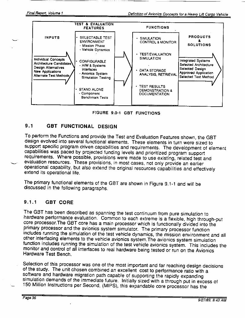
To perform the Functions and provide the Test and Evaluation Features shown, the GBTdesign evolved into several functional elements. These elements in turn were sized tosupport specific program driven capabilities and requirements. The development of elementcapabilities was paced by projected funding levels and prioritized program supportrequirements. Where possible, provisions were made to use existing, related test andevaluation resources. These provisions, in most cases, not only provide an earlieroperational capability, but also extend the original resources capabilities and effectivelyextend its operational life.
The primary functional elements of the GBT are shown in Figure 9.1-1 and will bediscussed in the following paragraphs.
9.1.1 GBT CORE
The GBT has been described as spanning the test continuum from pure simulation tohardware performance evaluation. Common to each extreme is a flexible, high through-putcore processor.The GBT core has a main processor which is functionally divided into theprimary processor and the avionics system simulator. The primary processor functionincludes running the simulation of the test vehicle dynamics, the mission environment and allother interfacing elements to the vehicle avionics system.The avionics system simulationfunction includes running the simulation of the test vehicle avionics system. This includes themonitor and control of all interfaces to real hardware being tested or run on the AvionicsHardware Test Bench.
Selection of this processor was one of the most important and far reaching design decisionsof the study. The unit chosen combined an excellent cost to performance ratio with asoftware and hardware migration path capable of supporting the rapidly expandingsimulation demands of the immediate future. Initially sized with a through put in excess of150 Million Instructions per Second, (MIPS), this expandable core processor has the
Page 36 ' 9/27/89, 8:43 AM
Final Report, Volume 1 Definition of Avionics Concepts for a Heavy Lift Cargo Vehicle
software tools and I/O ports to support the GBTs current and future Real-Time simulationrequirements.
The four other main elements of the GBT core are the Main Control Processor, Mass StorageUnit, Hard Copy Processor and Interconnecting network/buss structure. The Main ControlProcessor is primarily tasked with the allocation and control of GBT resources. It controlsmost of the various busses and networks running throughout the GBT and supervises use ofthe Mass Storage and Hard copy Processor. While functionally a part of the GBT Core, theMain Control Processor will probably reside in the Main Control and Demonstration center.
FIGURE 9.1-1 GROUND BASED TESTBED TARGET CONFIGURATION
9.1.2 MAIN CONTROL & DEMONSTRATION CENTER
Within this element rests the primary control and allocation of all the GBT resources. Centralto its function is the Main Control Processor that is linked to all the available resources by anextensive inter / intra lab communications network. The Main Control Center and
Demonstration Center are collocated because of their complementary functions. TheDemonstration monitors may be used to supplement the status displays available to thecore's Main Control Processor. The graphics processors will also supplement the MainControl Processor in controlling parallel operations going on within the GBT.
The Demonstration Center primarily consists of four graphics processors driving four largescreen monitors. The graphics processors are used to develop display and other support
Final Report, Volume 1 Definition of Avionics Concep, ts for a Heavy Lift Car_o Vehicle
type graphics. Working with the large screen monitors, the processors can reproducedemonstration graphics depicting anything from real-time test parameters to reproduction ofdemonstration graphics.
9.1.3 AVIONICS HARDWARE TEST BED
The Avionics Hardware Test Bed is the third major segment of the GBT Target Configuration.It contains the interfacing units, busses and harnesses necessary to accommodate the GBTBenchmark hardware. The benchmark hardware is a collection of current avionics units
which, when connected to the required interfacing harness, comprise a fully functionalavionics system.It provides a real world performance standard to which the candidatehardware can be compared. The Avionics Hardware Test Bed therefor facilitates
development and evaluation of new avionics systems,and components by providing a highfidelity, native environment in which they can be tested.
9.1.4 GUIDANCE & NAVIGATION RESOURCE LAB
The G&N Lab is one of the most important resources available to the GBT. Though capableof fully independent operation, in an acceptance test procedure role, its primary value is inclosed-loop simulation of an integrated avionics system. The precision 3-axis table cansupply all necessary stimuli, except acceleration, to evaluate the best inertial elements of theHLCV era. The Slave I/O interface box will provide the local real-time interfaces toaccommodate such testing.
9.1.5 INSTRUMENTATION RESOURCE LAB
The Instrumentation segment is a subset of the Avionics hardware test bed that permits localcontrol and monitoring of the test bed hardware or units under test. It functionally duplicitiesan instrumentation ground station and is equipped to analyze vehicle bus traffic.
9.1.6 SOFTWARE DEVELOPMENT FACILITY
A major design driver is the architecture of the user friendly software that yielded the efficientand highly compatible interface for potential users. The cost effectiveness of GBT usagerests squarely on its accessibility and its ability to accommodate several tasks in parallel.This translates to a modular set of software tools, tailorable to specific applications andexecuted with data that bounds the required performance regimes. The tailoring andselection of appropriate performance data is accomplished by a menu driven linkageprocess.The Software Development Facility will initially be located in the Main Control andDemonstration Facility while the basic GBT operational and benchmark software is beingintegrated. As the GBT phases into operation, the function of this element will shift to theprimary user interface. It will become the site where users will assemble the modularizedsoftware tools and simulations into the desired testing regimes. The Software DevelopmentFacility will also host the building of the demonstration graphics.
9.1.7 NAVIGATION AID & IMAGE PROCESSING EXTENSION
Page 38 9/27/89, 8:43 AM
Final Report, Volume 1 Definition of Avionics Concepts for a Heavy Lift Cargo Vehicle
This GBT extension is scheduled for Phase 2 implementation. It is designed to providedevelopmental support for the autonomous rendezvous and docking aids in the near termand approach and landing systems for the far term Fly Back Booster. See HLCV SecondQuarterly Review, Thursday 22 September 1988 for details.
9.1.8 POWER SYSTEMS EXTENSION
This GBT extension will be capable of testing new technologies in Power Systemscomponents and architectures. This Phase 2 extension will support not only the normalevaluation of candidate power system sources and architectures, but will be focused on EMApower supply development and testing.
9.1.9 FLUIDS & PNEUMATICS LAB
This GBT extension facility contains the hardware and special test equipment needed to testthe new Fluids and Pneumatic architectures and components. The Fluids & Pneumatics Labcontains flow and pressure sensing equipment, pressure regulation equipment, electronicvalves, a facility processor, a VME bus input/output interface chassis, and bottled fluids andgases.The extension facility shall have thick safety walls and a pressure pit for this highpressure LN2. The facility shall also be capable of running remote when operating with thehigh pressure.
9.1.10 ACTUATOR LAB
This resource lab will provide a dynamic performance evaluation facility primarily aimed atlarger, fast response actuators used in Trust Vector Control systems. With the emergence oflarge numbers of clustered engines as a solution to the heavy lift booster requirements,EMAs are gaining popularity. The advantages of being able to link the Power Systems andActuator Labs together via the GBT is seen as an attractive Phase 2 capability.
9.1.11 PROPULSION SYSTEMS LABS
MSFC has long been the site of propulsion system development and test. The GBT wouldprovide a way to combine the existing,high fidelity,.propulsion system hardware emulationsand simulations with the avionics system simulations to provide integrated, end to endtesting. Particularly useful will be the capability to evaluate control system performance usingthe clustered engine configurations of the future.
9.2 GBT IMPLEMENTATION
From the beginning, it was recognized that the Ground Based Test beds capabilities wouldbe tied to meeting current program system testing requirements. The GBTs role was toencompass vehicle simulation and testing needs from inception to the Preliminary DesignReview (PDR). Looking at the projected vehicle developmental schedules, it was all too clearthat the first operational GBT capabilities would have to be focused on the criticaldevelopmental problems. If vehicles like the Shuttle C or STV were to be supported prior totheir PDRs the GBT must be at least operational by August 1990.
Page 39 9/27/89, 8:43 AM
Final Report, Volume I Definition of Avionics Concepts for a Heavy Lift Cargo Vehicle
Software model development is another key factor in the implementation plan. Fidelity of thevehicle dynamic and system models is critical to establishing the GBT as a valuable programdevelopment resource. This usually requires actual hardware being used to develop andverify the fidelity of the respective software models. Availability of similar hardware oftenproves to be another pacing element. The basic GBT hardware and software design ismodular and thus can be changed easily to accommodate different requirements. The earlyphases of implementation require the building of a specific number of these basic modules tosatisfy a limited number of needs. To satisfy a greater set of requirements relatively few newmodules are required.
LAB PRELIMINARY IMPLEMENTATION SCHEDULE
198g 1990 1991 1992 1 993 lgg4 1995
HLCV Related Milestones• SDV.2ES IOC 1tie3
• SDV-2RS IOC lgg5
• FRWB _OC 1996.2000÷
• PRCV IOC 1998-20OO+
SHUI"rLE C IOC 1994ALS IOC 1996-98
Upper Stages
• OTV IOC TaD•AOTV IOC TBD
INITIAL Lab MileStones.Procurement
• S/W Development
•I.VW Oeelgn • Feb
• FII H/W Acq
• Facility Prep•Lab Activation
RFP Start PD COR F : On Pad I(
ALS P -se 3_i, Start
al • LA I lOC
_valution or Oov nstreat lOG
Lab Program Drivers
4 Year Development Cycle
• IOC First Launch. Delivery to pad 1 year prior to Launch.
Full Scala Engineering Development Syslems Inlegratlon Laboratory with Pathfinder Activity
• GBT Supports Early PORe
FIGURE 9.2-1 IMPLEMENTATION SCHEDULE
Figure 9.2-1 shows an early implementation schedule and its assumptions. One of the mostdifficult problems of the implementation schedule, shown earlier in figure 1.2-2, is the amountof work to be done in the first phase. Between February 1989 and August 1990, over 60% ofthe total task must be accomplished. This is not consist with the relatively low front endfunding guidelines that were provided for this study. Figure 9.2-2 shows this problemgraphically.
Page 40 9/27/89, 8:43 AM
Final Report, Volume 1 Definition of Avionics Concepts for a Heavy Lift Cargo Vehicle
IMPLEMENTATION ISSUES
11989 1990 1991 1992 1993
I
rf
I
J
j_f
v
A
r
v
f
Iy_
J
J_
1994
oI_C
ISSUES• SOFTWARE DEVELOPMENT TIME
- 70% of Target S/W needed by Aug 1990• HARDWARE ACQUISITION
- 3 Axis Table requires 1 Year lead time• FACILITY
- Site modifications not completed for • 1
Q21OC TARGET IOC
LEGEND
J m Projected FundingCurrenl Requirements
FIGURE 9.2-2 PROJECTED FUNDING LEVELS VS TASK
9.3 GBT FUNDING
The bottom line for GBT success is being able to supply the most cost effective and useful testfacility at the time when new programs need it the most. This implies that the projects arewilling to pay their way and plan for such usage initially. This idealistic form of funding mustbe recognized as supplemental to basic level of funding needed to initially implement andlater maintain GBT operations. Internal Research & Development projects are also a sourceof funding. This type of function typically accelerates the application of useful, newtechnologies and test concepts upon which later major programs are built.
Table 9.3-1 shows a summary of the element costs associated with the Phase 1 GroundBased Test Bed. Note that these are ROM costs with no wraps. More up to date, loadedcosts are available in the Final Report Addendum.