TENDER DOCUMENT NIT No. DLI/C&E/WI-675/525 FOR Tender for Design, Engineering, Manufacturing at works, Supply, testing and commissioning of “Addressable type Pull Cord & Belt Sway Switches including addressable panel & Associated Works” for the project of “Augmentation of Fuel & Flux Crushing Facilities (Package-064) of Bhilai Steel Plant, SAIL” VOLUME- 2 B (TECHNICAL SPECIFICATION & SCOPE OF WORK) ENGINEERING PROJECTS (INDIA) LIMITED (A GOVT. OF INDIA ENTERPRISE) Core-3, Scope Complex, 7, Lodhi Road, New Delhi-110003 TEL NO: 011-24361666 FAX NO. 011- 24363426
Transcript
TENDER DOCUMENT
NIT No. DLI/C&E/WI-675/525
FOR
Tender for Design, Engineering, Manufacturing at works, Supply, testing and commissioning of “Addressable type Pull Cord & Belt Sway Switches
including addressable panel & Associated Works” for the project of “Augmentation of Fuel & Flux Crushing Facilities (Package-064) of Bhilai Steel Plant, SAIL”
VOLUME- 2 B
(TECHNICAL SPECIFICATION & SCOPE OF WORK)
ENGINEERING PROJECTS (INDIA) LIMITED (A GOVT. OF INDIA ENTERPRISE)
Core-3, Scope Complex, 7, Lodhi Road, New Delhi-110003
TEL NO: 011-24361666 FAX NO. 011- 24363426
Contents- (Volume-2B)
NIT No. DLI/C&E/WI-675/525
S.No, Description
1 Volume-2B (Scope of Work & Technical Specs.)
-Scope of work
-Technical Spec. Chapter 4
-GS -9 Painting
-GS -5 Inspection
BSP Pkg-064 NIT No.- DLI/C&E/WI-675/525
Page 1 of 4
Scope of Work - Addressable type Pull cord & Belt Sway
Switch
Scope of work for Addressable type Pull cord Switch & Belt Sway Switch shall include (but
not limited to Design, Engineering, Manufacturing at works, Supply, testing and
commissioning of “Addressable type Pull Cord & Belt Sway Switches including addressable
panel & Associated Works” for the project of “Augmentation of Fuel & Flux Crushing
Facilities (Package-064) of Bhilai Steel Plant, SAIL”
Supply of Addressable type Pull Cord Switch & Belt Sway Switch complete in all
respects with all the components, accessories & desired nos. of group control panel
required to make suitable as addressable so that all the information shall be available
at one place for different area.
Two Numbers of group control panel as per following detail is required which shall be
in the bidder’s scope of work & the same shall be suitably placed as per the
requirement.
GROUP CONTROL PANEL -1 FOR CHP AREA (13 Conveyors)
SL NO. NAME OF CONVEYOR APPROX BSS QTY APPROX PCS QTY
1 Y11-200 4 8
2 Y11-202 4 6
3 Y11-203 2 2
4 Y11-204 4 4
5 Y11-205 2 2
6 Y7-12 2 4
7 Y7-35 4 6
8 Y11-207 4 12
9 Y11-206 2 2
10 Y11-208 4 6
11 Y11-209 2 2
12 SHUTTLE CONV Y11-210 2 2
13 SHUTTLE CONV Y11-211 2 2
GROUP CONTROL PANEL -2 FOR FUEL & FLUX AREA (18 Conveyors)
SL NO. NAME OF CONVEYOR APPROX BSS QTY APPROX PCS QTY
1 C104 4 4
2 RC-106 4 4
3 C106A 4 10
4 RC-CK2 4 4
5 C107A 4 8
6 C107B 4 4
7 C110A 2 4
8 C111A 4 4
9 C113A 4 4
10 C112A 4 4
11 L114A 4 6
12 L111A 4 6
13 RSC-L118 4 4
14 RSC-L106 4 4
15 L115 2 2
16 L120 2 2
17 L105 2 2
18 L117 2 2
BSP Pkg-064 NIT No.- DLI/C&E/WI-675/525
Page 2 of 4
All group control panel shall be suitably designed & should have facilities i.e.
communication port etc. to interface/communication with R/IO panel (Schneider
make) located in the same premises so that all the data (Specific address of operated
PCS & BSS of each conveyor) can be transferred to R/IO panel. Bidders to note that
preferred mode of communication shall be MODBUS communication type. Bidders has
to inform any data is required for communicating between the addressable panel &
HMI during final designing of the system.
Each Pull Chord Switch & Belt Sway Switch shall have facilities for 2NO+2NC potential
free contacts for our use. Also switches have facilities for termination & glanding for at
least 2Nos. 5CX2.5sq. mm armored Cu cable for loop in loop out of switches.
In Group control panel, there shall have facility of 2 relays (with 2NO+2NC potential
free contact) for each conveyor, one for PCS operated & other for BSS operated, &
every potential free contact shall be wired up to terminals.
Group Control panel shall have facilities to bypass BSS for each conveyor with proper
indication of bypass mode of BSS for each conveyor & shall have proper arrangement
for recognizing whether BSS is in bypass mode or in circuit. (Push type arrangement is
not acceptable)
The scope of bidder shall be deemed to include all such items which although are not
specifically mentioned in the specifications but needed to make system complete in all
respect with all mountings, fittings, fixtures and standard accessories i.e. nuts, bolts,
& washer etc. as required.
EPIL will provide 240 volt supply at one point in the panel, further distribution of the
same shall be in bidder’s scope & any other type of supply so required for proper
operation of the system shall be arranged by bidder.
The design of equipment or any components/accessories used shall be or selected as
per supply voltage mentioned in the GTS.
Proper earthing of all electrical equipment will be carried out as per IE rules and IS:
3043. Suitable arrangement shall be provided in all the switches, panel etc. so that
earthing of each equipment can be connected from external grid.
Bidder has to submit Basic engineering, detailed engineering and reference category of
drawings, operating software and documents in requisite copies for approval of BSP /
MECON. Further the successful bidder will furnish final basic & detailed engineering
drawings, manufacturing drawings of fast wearing items and non-standard items, as
built drawings, erection drawings/ documents, operating software, operation and
maintenance manuals in soft editable format.
Getting BSP/ MECON approval of the drawings, documents and calculation to be
submitted by the successful bidder, obtaining required approval from statutory
authorities, providing adequate personnel, equipment, tools & tackles for timely
completion of the project.
Supply of all commissioning & start-up spares, special tools & tackles and insurance
spares. A list of such commissioning & start-up spares and insurance spares shall be
indicated separately in the offer. Bidder shall furnish separately priced list for two
years O&M spares.
BSP Pkg-064 NIT No.- DLI/C&E/WI-675/525
Page 3 of 4
Specialized training to BSP’s / Consultant’s personnel for operation, maintenance, for
smooth handing over shall be included in bidder’s scope.
Testing and cold trial run of systems/ sub - systems and integrated testing including
load test, overload test as per applicable standards, accuracy and performance testing
shall be carried out by the successful bidder on continuous basis along with associated
facilities followed by commissioning. On successful commissioning of the various sub-
systems, PG test shall be carried out.
Providing all drawings and documents with operation & maintenance manuals.
Bidders are required to quote the prices as per price bid only in original. In addition to
prices as per price schedule for SUPPLY, TESTING & COMMISIONING, RECOMMENDED
SPARE (OPTIONAL NOT TO BE CONSIDERED FOR BID EVALUTION). Bidders are also
required to quote the Addition / Deletion prices for addressable type Pull Cord Switch &
Belt Sway Switch control/module panel as per schedule enclosed in the price bid.
These rates will be applied during any changes occurring at detail engineering stage.
Drawings /Documents Submission
Documents/Information to be submitted by bidder with offer:
List of commissioning spares and start up spares.
List of special tools and tackles if required.
Price schedule for supply & installation, calibration, testing and commissioning work
as per the format.
List of recommended spare parts for 2 (Two) years trouble free operation and
maintenance as per the format.
Technical specifications, Catalogues/ Leaflets and O&M manuals
Reference list of customers for similar supply of items.
Unpriced copy of price schedules (with technical bid).
No deviation declaration to NIT technical and commercial terms and conditions and
duly signed with date and stamped copy of NIT Vol-1, Vol-2 (2A, 2B & 2C), Vol-3 &
Vol-4.
Approximate weight of the equipment.
Documents/Information to be submitted by successful bidder for Approval/Reference
Drawings related to General arrangement, layout and block diagram of CHP, CSP &
Fuel & Flux series conveyors system.
Mounting arrangement Drawings
Bill of materials
Technical specifications
Pre requirements for Installation of Addressable type PCS/BSS system
BSP Pkg-064 NIT No.- DLI/C&E/WI-675/525
Page 4 of 4
Earthing layout drawing
Cable schedule
Wiring Diagram and termination drawings.
Technical data sheet of all components, cables; electronic devices etc. for panels of
PCS/BSS.
Total power consumption details
Approximate weight of the equipment
Internal test reports and certificates
Accuracy / Performance check reports
Test reports for degree of protection on enclosure of sensing element.
Quality assurance for the addressable type PCS/BSS, panels & other related
components.
Operation and maintenance manuals
Other drawings/ documents as per BSP/ MECON requirement for the system and drgs
as per the recommendation of manufacturer & exclusion if any.
STEEL AUTHORITY OF INDIA LIMITED BHILAI STEEL PLANT (BSP)
CONTRACT AGREEMENT FOR Augmentation of Raw Material Receipt & Handling
facilities with new OHP, Part-B (PACKAGE No. – 061)
CHAP-4.10 ELECTRICS Page 1 of 65
4.10 ELECTRICAL POWER DISTRIBUTION, DRIVES, CONTROL & ILLUMINATION
4.10.01 General
This section covers major features of Power Distribution System, Shop-Electrics, Drives, Control, Automation and Illumination System to be supplied by Contractor for the Ore Handling Plant Part-B Complex.
The Contractor will refer to General Technical Specification (GTS) for Electrics and Illumination for detailed specification of equipment / components. This Contract Specification (CS), General Technical Specification (GTS) including Preferred Makes for Equipment and supplies (GS-13) and other attached documents / Annexure E-01, E-02, E03 Commissioning Spares), E-04 (Tools & Tackles), E-05 as a whole will comprise the complete Contract Specification. These are complementary and anything laid down in one and not in other will be deemed as binding, as though laid down in the Contract specification as a whole. In case of conflict between the Contract specification and GTS, the Contract specification (CS) will prevail.
4.10.02 HT Power Supply System & Battery Limit Power supply for the New Ore Handling Plant Part-B Complex will be made
available from the 11kV and 6.6 kV switchboards proposed to be installed at HT substations (HTSS) which will be located at OHP-B premises and different locations under a separate package by Employer (package no. 071). Refer enclosed drawing no. MEC/S/9101/11/E1/06/00/00/061.01/R2
The scope of work of the Contractor will commence from the outgoing terminals of 11kV and 6.6 kV switchboard located at new / existing HTSSs for supplying power to LTSS and HT motors & Yard machines respectively under this package.
11 kV Switchboards for supplying power to all LTSSs and 6.6 kV Switchboards for supplying power to all HT Motors and yard machines only will be provided by Employer at HTSSs. Supply, laying and termination (at both ends) of all HT & Control Cables from HT switchboard to LTSS & HT motors, yard machines will be in the scope of Contractor. Power to all the HT motors will be supplied from the 6.6kV HT Switchboards.
Adequate number of LT Substations (LTSS), (at suitable locations to be decided by the Contractor) each comprising of LT switchboard along with two transformers will be included by the Contractor in his scope of work. The
STEEL AUTHORITY OF INDIA LIMITED BHILAI STEEL PLANT (BSP)
CONTRACT AGREEMENT FOR Augmentation of Raw Material Receipt & Handling
facilities with new OHP, Part-B (PACKAGE No. – 061)
CHAP-4.10 ELECTRICS Page 2 of 65
transformer rating will be worked out on the basis of guidelines given in General Technical Specification. However, the rating of transformers will be 2000/ 1000 kVA depending upon the load. The interconnection between transformer secondary and LT switchboard will be through bus ducts.
The Contractor will indicate the numbers of 11kV and 6.6 kV feeders required by them from the HTSS during Basic Engineering to provide HT feeders by Employer. The Contractor will indicate the details of connected load (KW) & Maximum Demand in 15 min. duration for each feeder and also the overall expected maximum demand in 15 min duration for the entire plant under normal operating conditions. The following are to be considered in addition to the equipment specification spelt out in GTS. a) The vector group for all distribution transformers (LT S/S) will be of Dyn11
only to take care of circulation of harmonic currents. However, care should be taken not to envisage mixing of supply with the existing LT power sources of 2.5 MT area as the existing distribution transformers are of Yy0 vector group.
b) Separate analogue voltmeters for line voltage & bus voltage and ammeter in each of the three phases will be provided.
c) All out going ACBs will be 800A, 1000A or 1600 A as per requirement with protection settings selectable at site.
d) Check-synchronising relay will be provided wherever sectionalizing is envisaged between two different sources of power supplies.
e) Care should be taken to avoid location of LT Substations under Conveyor galleries/ dust prone areas.
f) LT Bus duct insulators will be of porcelain.
g) The CT mounting arrangement inside the cable chambers of all feeders will be such that CTs and secondary connections will be easily accessible for maintenance, replacement, etc.
h) For LT Bus duct/ bus bars, the minimum clearance will be considered as follows in line with GTS
• phase to phase : 25.4 mm • phase to earth : 19 mm
i) Training of personnel on operation and maintenance of the new
equipment at manufactures work will be arranged by the supplier.
STEEL AUTHORITY OF INDIA LIMITED BHILAI STEEL PLANT (BSP)
CONTRACT AGREEMENT FOR Augmentation of Raw Material Receipt & Handling
facilities with new OHP, Part-B (PACKAGE No. – 061)
CHAP-4.10 ELECTRICS Page 3 of 65
Each of the LT substations will have the following facilities:
a) The substation design will be dust proof and all entry points will be provided with double door arrangements.
b) Sufficient quantity of fire extinguishers at various locations will be provided as part of safety equipment inside sub-station.
c) Air cooling facility will be provided in all LT substations with air washing. d) Lighting circuits of different rows will be controlled by different MCBs for
better energy saving. e) Breaker handling facilities will be provided. f) Tools & tackles along with store room facilities will be provided. g) Two nos of 4 legged wooden stools of height 1m and 4m each will be
provided. h) Chain pulley block or telpher arrangement will be provided. Following HT / LT Power and motor feeders required for this package have already been included by the Employer’s in other package for the Contractor’s use. Supply of cables from Employer’s boards, laying, termination at both ends, erection, commissioning etc. will be under the Contractor’s scope. Contractor to note that the feeder rating and locations mentioned are tentative only. Final ratings, nos. and locations will be decided during detail engineering.
A. HT Power and motor feeders for Contractor’s use :
Feeders for Contractor’s use Sl. No.
HT Sub Station
Location Description Nos.
1. HT Sub Station (SS-46)
Near New Storage Yard
LTSS, HT Motors and yard machines
As per Requirement
Conveyor Z10-C1 1 No. 2. HT Sub Station (SS-45)
Near existing Storage yard (Under HT S/Stn OHP-A)
Conveyor Z10-C2 1 No.
3. HT S/Stn (SS-53- SS-SMS-II)
Between Jh-16 to JH-27
LTSS (11/0.433kV, 2000/1000 kVA transformers)
2 Nos.
Conveyor Z15-C1 2 Nos. 4. HT S/Stn (SS-57)
Near Blast Furnace Conveyor Z15-C2 2 Nos.
LTSS (11/0.433kV, 2000kVA transformers)
2 Nos.
STEEL AUTHORITY OF INDIA LIMITED BHILAI STEEL PLANT (BSP)
CONTRACT AGREEMENT FOR Augmentation of Raw Material Receipt & Handling
facilities with new OHP, Part-B (PACKAGE No. – 061)
CHAP-4.10 ELECTRICS Page 4 of 65
5. HT S/Stn (SS-60)
Near Lime Plant LTSS (11/0.433kV, 2000kVA transformers)
4 Nos.
B. LT Power and motor feeders for Contractor’s use :
Feeders for Contractor’s use Sl.
No. LT Sub Station
Location Description Nos. Rating
Power Supply Feeders
1 No. 275 kW
Power Supply Feeders for MCP
2 Nos. 160 kW
1. LTSS-1 and 2
Near J-3
Power Supply Feeders for MCP
1 No. 125 kW
Power Supply Feeders for MCP
2 Nos. 180 kW
MCC 2 Nos. 350 kW PDB 2 Nos. 400 A
2. LTSS-4 Near J-4
MLDB 2 Nos. 400 A 4.10.03 Scope of work
The scope of work of Contractor will cover design, basic and detailed engineering, submission of drawings for approval, manufacture, factory testing, inspection by client / consultant, packing, loading, forwarding, delivery at Plant site, loading / unloading, storage, handling of material/equipment to erection site, erection, no-load and load testing, commissioning, PG test, PAT/FAT and liquidating the defects and handing over all electrics related to drives & control, illumination for complete & satisfactory operation of Ore Handling Plant on turnkey basis. Contractor’s scope of work for New OHP-Part-B also includes necessary electrics and PLC based automation system including upgraded of existing automation system for integration of existing drives of OHP and Priority conveying routes upto JH-27/JH-42. Any item or equipment not specifically mentioned but essential for process and technological requirement, proper installation, reliable operation, maintenance and safety of plant, equipment and personnel will be included by the Contractor in his scope of work.
STEEL AUTHORITY OF INDIA LIMITED BHILAI STEEL PLANT (BSP)
CONTRACT AGREEMENT FOR Augmentation of Raw Material Receipt & Handling
facilities with new OHP, Part-B (PACKAGE No. – 061)
CHAP-4.10 ELECTRICS Page 5 of 65
2. Each double ended substation will comprise of 11/0.433 kV Distribution transformers, 415 V PCC, 415 V bus duct, ACDB, MLDB, LDB, HT/ LT power & control cables and other necessary items as required for completion and successful operation of the power distribution network, in an integrated manner.
3. - Vacuum circuit breaker (VCB) without protections in the transformer room if transformer is fed from remote HT switchboard for tripping of upstream breakers
- Push Button stations with trip PBs (press to lock and turn to release) in the transformer room if transformer is fed from HT switchboard located in the same building for tripping of upstream breakers.
4. Power and control cables, Cable termination kits, laying and termination (at both ends) of all associated power and control cables from the Employer’s 6.6 kV switchboard. Only 11kV (UE) grade cable will be used for 6.6kV (UE) applications.
5. AC distribution boards (PDB) - Single front, non draw-out type, sheet steel enclosed, modular construction with IP54 enclosure, having two incomer with a bus coupler will be provided for auxiliary equipment of LTSS.
6. Adequate numbers of Lighting Distribution Boards (LDB) for Power supply to various Sub Lighting distribution Boards (SLDB).
7. Illumination system of the Sub-station rooms. Illumination system will include all type of light fittings/fixtures.
8. Power and control junction boxes for termination of field cables. 9. Maximum demand (MD) of the MCC will be calculated considering the
following: a. Working load of the MCC will be calculated based on the motor kW
rating. b. The load factor will be considered as follows:
For continuous drives – 0.9 For intermittent drives like sump pumps etc. – 0.6 For electrically actuated valves / dampers – 0.2 For maintenance loads like hoists, cranes etc. - 0.4
c. Load factor will be applied on the kW rating of motor. d. Diversity factor will be considered as one.
STEEL AUTHORITY OF INDIA LIMITED BHILAI STEEL PLANT (BSP)
CONTRACT AGREEMENT FOR Augmentation of Raw Material Receipt & Handling
facilities with new OHP, Part-B (PACKAGE No. – 061)
CHAP-4.10 ELECTRICS Page 6 of 65
e. Spare feeders will also be considered for calculation of maximum demand as per guidelines indicated in Sl. No.2
f. Load of power supply feeders will be corresponding to the load being fed with 0.9 load factor.
g. Cyclic load will be converted to continuous load and will be used for MD without load factor. (e.g. 22kW motor at 40% duty factor will have continuous load as 22 x square root of 0.4)
Construction Power Supply :
The facilities for distribution of construction power supply will be in the scope of the Contractor.
For construction power supply, one no. outgoing feeder of 415/230V AC, 3ph / single phase, 50 Hz will be made available to the nearest established sub-station by the Employer.
Supply, erection, testing and termination at both ends of incoming power cable to construction power distribution board and regular maintenance of the cable will be included in the scope of supply and work.
II DRIVES, CONTROLS & ILLUMINATION SYSTEM
1. All HT and LT AC / DC motors, actuators, brakes etc. as per
technological and process requirement. HT motor winding and bearings, temperature sensors, vibration sensors
will be hooked up with PLC for monitoring. Surge suppressors will be provided at motor end of all the HT motors.
2. Generally Squirrel Cage Induction Motor with DOL starter / VFD / Soft Starter will be provided. Use of Slip ring motor in general will be avoided. Suitable Rotor contactor panels and SS-grid Resistance Boxes will be provided for slip ring motors if inevitable.
3. Indoor 415 V LT MCC and Control panel with CT, PT, metering and Protection etc. as required.
• Motor Control Centers for New OHP-Part B will be Intelligent, draw-out type with two incomers and bus coupler for control of drives of rating up to 90kW of various technological units having communication with Plant Automation System.
STEEL AUTHORITY OF INDIA LIMITED BHILAI STEEL PLANT (BSP)
CONTRACT AGREEMENT FOR Augmentation of Raw Material Receipt & Handling
facilities with new OHP, Part-B (PACKAGE No. – 061)
CHAP-4.10 ELECTRICS Page 7 of 65
For control of drives of rating from 110kW to 200kW Intelligent type Motor control panels (MCPs) having communication capability as above.
• MCCs for drive motors of New series conveyors parallel to existing conveyors from OHP-I to Junction House JH-27/JH-42 will be non Intelligent draw-out type and will be connected to Rockwell system / L&T system by providing remote I/O stations as per existing control philosophy.
For control of drives of rating from 110kW to 200kW non-Intelligent type Motor control panels (MCPs) will be provided.
• Control panels for Stacker, Reclaimer, Wagon Tippler, Tripper car, crane, hoist, AC/ventilation system etc will be conventional, non draw-out type. All control panels on the mobile machines will be mounted on anti vibration pad.
• Stacking & Reclaiming conveying routes will have separate MCC.
• Separate MCC for the drives upto JH-15 for new series of OHP-I.
• Separate MCC for the drives from JH-15 to JH-27/JH-42 for new series of OHP-I.
• Electronic over load relay upto 90kW motor and Motor Protection Relays for motors above 90 kW rating in conventional type (non-intelligent) MCC / Control panel will be used.
• Local/Remote selector switch will be mounted on MCC & Control Panel.
4. VVVF converters for 415 V motor drives having requirement of speed control where process requirement calls for variable speed application. All drives will have communication capability with Plant Automation System.
VFD will have following features :
Minimum rating of AC drives and reactors will be 150% of the full load RMS current of the motor.
Automatic disconnection of individual Motor in case of failure of AC drive.
Use of isolation transformer for more than 90 KW drive and use of series rector for less than 90 KW drive for VFD application.
5. Soft Starter :
STEEL AUTHORITY OF INDIA LIMITED BHILAI STEEL PLANT (BSP)
CONTRACT AGREEMENT FOR Augmentation of Raw Material Receipt & Handling
facilities with new OHP, Part-B (PACKAGE No. – 061)
CHAP-4.10 ELECTRICS Page 8 of 65
• All HT Motors for conveyor drives will have High Voltage Flux
Compensated Magnetic Amplifier (FCMA) Soft starter for low starting current. FCMA soft starter will have suitable By-pass contactors and controls to ensure full voltage running of the motor. FCMA soft starter will be indoor duty, rugged in construction, user friendly and maintenance free.
FCMA Soft starter for HT conveyor motors will be connected to motor at neutral end with suitable enclosure to prevent the dust entry.
• Soft starter will be provided for LT motors of rating more than 75kW.
6. UPS system consisting of SMF battery bank for 30 minute back up
incase of power failure, Battery charger, UPS Power distribution boards & sub-distribution boards for distribution of UPS power supply to control & Automation equipments, Instrumentation system equipment, FDA system, Weighing system & any other equipment as per requirements.
7. Local control stations housing push buttons, indication lamps etc. for
all drives. LCS for LT motor above 45kW and HT motor will have Ammeter also. LCS for conveyors will have belt sway switch bypass.
8. Power distribution boards (PDB) with two incomers and one bus coupler for repair network like welding sockets, maintenance cranes and hoists. All PDBs to be mounted in Technological/Auxiliary/Service buildings (Other than Electrical room) will have double doors.
9. Main Lighting Distribution Boards (MLDB) with two incomers and one bus coupler for Power supply to various Lighting distribution Boards (LDB).
Adequate nos. of LDBs and Sub Lighting distribution boards for providing power to light fittings.
10. Emergency lighting distribution boards (ELDBs) with two incomers and one bus coupler for Power supply to various Emergency Sub Lighting distribution Boards (ESLDBs).
• Adequate nos. of Emergency Sub Lighting Distribution Boards (ESLDBs) for providing power to emergency light as given Emergency lighting in all Junction houses, Process / technological buildings, pump houses, compressor houses, conveyor tunnels, underground premises, LTSS, Dispatcher / Control rooms,
STEEL AUTHORITY OF INDIA LIMITED BHILAI STEEL PLANT (BSP)
CONTRACT AGREEMENT FOR Augmentation of Raw Material Receipt & Handling
facilities with new OHP, Part-B (PACKAGE No. – 061)
CHAP-4.10 ELECTRICS Page 9 of 65
staircases, entry / exit of building, office rooms, attendant / operators rooms, shift in charge rooms, canteen / rest rooms etc.
• 10% Emergency lighting in conveyor galleries. 11. DCEM Brakes will be used for Conveyors and brake panels will be
housed in MCC room.
12. All LT motors for conveyors will be S6 duty and will have class F insulation with temperature rise limited to class B. Inverter duty motors (used for VFD application) will have class H insulation with temperature rise limited to class F.
13. Surge protection device will be provided at the incoming side of MCCs, VFDs, PLCs/Remote I/O stations etc. to protect the system/equipment as required.
14. All field devices, valves, safety switches like Pull chord switches and belt sway switches, zero speed switch, chute jamming switches and Proximity switches, Warning hooters, photo-electric sensors, level sensors, relays, limit switches, binary encoders, position transducer, isolators, speed sensors etc. as necessary for the process and control of the material handling equipment / system and its all associated / auxiliary equipment / systems.
Addressable type PCS, BSS, ZSS and Belt rupture protection switches will be provided for all new conveyors. Proximity type Limit switches will be used for shuttle conveyors, tripper car etc. Sensing distance of proximity in the Zero Sped Switch will be 60 mm.
15. All HT / LT Power, control, signal, communication cables (fiber optic / electrical), special cables, rubber insulated flexible cables, illumination cables etc. as required. All HT and LT Power cables will be XLPE insulated. All HT Power cables will be 11kV (UE) grade and FRLS sheathed. LT Control cables will be PVC insulated and minimum size will be 2.5sq. mm.
16. 415V, 100A interlocked switch socket outlets for repair network,
welding sockets at different floor, premises, buildings and area of Ore Handling Plant. Maximum 3 nos. Welding sockets will be connected to one feeder with 100Amp MCCB rating & minimum size of cable will be 3.5 x 70sqmm. Wagon Tippler Building will have adequate nos. of circuits from PDB
STEEL AUTHORITY OF INDIA LIMITED BHILAI STEEL PLANT (BSP)
CONTRACT AGREEMENT FOR Augmentation of Raw Material Receipt & Handling
facilities with new OHP, Part-B (PACKAGE No. – 061)
CHAP-4.10 ELECTRICS Page 10 of 65
so that minimum 4 nos. welding machines can run at a time.
17. 240V, 15A and 24V, 5A receptacles from Lighting Distribution Board / Sub Lighting Distribution Board.
18. Load break isolators for maintenance crane, hoists, tripper car etc. to
be located near the equipment.
19. Power and control junction boxes for termination of field cables.
20. Power trolley line conductor (DSL) / Festoon Cable trolley system / Plastic Cable Carriage system including rails / angles, supporting brackets, insulator assembly, junction box etc. will be provided as follows :
Festoon Cable trolley system for hoists etc. Plastic Cable Carriage system for power and control trailing cables
for Side Arm Charger, shuttle conveyors, EOT cranes etc.
21. Cable Reeling Drum with stall torque induction motor will be provided for Tripper Car. Tripper car will have interlocking of chute clogging switch with conveyor through wireless radio communication. Interlocking with the CRD control cable will be given as back-up.
22. Illumination of the plant covering new storage yards, wagon tippler
inhaul and outhaul area, wagon tippler area, Road in and around the proposed Ore Handling Plant, Sub- station rooms, MCC rooms, Control rooms, Ventilation rooms, conveyors, Junction houses, various technological / auxiliary buildings and other installations of the plant by providing Lighting Transformer, Main Lighting Distribution Board, Lighting Distribution Boards, Sub-lighting Distribution Boards, Feeder pillars, Light Fittings, Lighting towers, high mast, low voltage switch sockets, conduits, Ceiling fans, Exhaust Fans, all lighting cables etc.
Total plant lighting system will comprise of the following categories of lighting system. • Normal /240V AC lighting system. • 24V AC maintenance lighting system. • Emergency lighting system.
23. Contractor will provide Emergency lighting (apart from ELDB) from
UPS distribution board for the following areas. • LTSSs / Electrical premises
STEEL AUTHORITY OF INDIA LIMITED BHILAI STEEL PLANT (BSP)
CONTRACT AGREEMENT FOR Augmentation of Raw Material Receipt & Handling
facilities with new OHP, Part-B (PACKAGE No. – 061)
CHAP-4.10 ELECTRICS Page 11 of 65
• Despatcher / Control rooms
24. Portable Emergency lights will also be provided in strategic areas like LTSSs, Electrical premises, control rooms / Despatchers, staircases, entrance of cable tunnels / basements, escape routes, attendant / operators room in the technological buildings etc.
25. Complete electrics including motors, control panel, LCS, Brakes with panel, field devices, cables etc. for Conveyors, Screens, Actuators, valves, gates, vibro feeders, belt feeders etc. as per technological requirement.
26. Completes electrics including motors, control panel, LCS, Brakes with panel, field devices, cables etc. for Shuttle conveyors, Tripper cars, Cranes, Hoists etc. required under Ore Handling Plant.
27. Completes electrics and load cell for Weigh feeders, Weigh hoppers, Belt scales etc. as per technological requirement. Conventional load cell type Belt Weigh Scale / non-contact type Belt Weigh Scale will be provided as per site requirement. Type and location of them will be decided during detailed engineering in consultation with Employer / Consultant.
28. Completes electrics required for Suspended magnets, In Line Magnetic Separators, Metal presence detectors etc. as per technological requirement.
29. Complete electrics, controls, instruments, level controllers, solenoid valves, Bag filters, Timer controls etc. for the Dust suppression system, Dust extraction system, Ventilation, Air Conditioning system, Compressor required under Ore Handling Plant (Part-B).
30. Completes electrics including motors, control panel, LCS, level sensors, cables etc. for sump pumps, slurry and dewatering pumps will be provided in underground floor of technological building/ Junction houses, Tunnels, cellar etc. 415V, 100A Sockets will also be provided near sumps.
31. Completes electrics including motors, control panel, LCS, level sensors, cables etc. for all pump houses, fire fighting system etc.
32. Complete electrics for Bin vibrators with rectifier panels and Air Blaster with solenoids, control panels, cables etc. for Bunkers as required.
33. Complete electrics for sampling systems covering motors, control panels, cables LCS etc. as required.
STEEL AUTHORITY OF INDIA LIMITED BHILAI STEEL PLANT (BSP)
CONTRACT AGREEMENT FOR Augmentation of Raw Material Receipt & Handling
facilities with new OHP, Part-B (PACKAGE No. – 061)
CHAP-4.10 ELECTRICS Page 12 of 65
34. Scope of work and Battery limit for Electrics and Automation for upgradation / modification of existing drives / mechanism are defined in the Clause No. 4.10.11.
35. Automation system of OHP (Part-A) will be interfaced with Automation system of New OHP (Part-B) so that entire OHP consisting of existing OHP, new OHP (Part-A) and proposed OHP (Part-B) can be operated in an integrated way from a common automation platform.
36. Complete electrics for Wagon tippler and Side Arm charger (SAC).
• Motors with necessary accessories and brakes.
• Conventional type Control panel, VVVF drive panels, PLC panel at Electrical room and Control panel on SAC.
• Control desk both at control room and on SAC. Provision in control desk for control of Dust Suppression system for Wagon Tippler.
• Weighing facility with load cells for recording and transmitting data of incoming materials to Despatchers D1 & D2 and central control room.
• Local Control Station and Field devices such as actuators, valves, photo-electric sensor/relay, limit switches, proximity switches, encoders, position transducer, isolators, safety switches, speed sensors, junction boxes; warning hooters, Rail Clamp, Earth shoes etc.
• Plastic Power cable carrier system and necessary Flexible cables.
• Air Conditioning / Ventilation facility for Electrical panel room and Control room.
• All power, control and special / instrument cables, cabling, terminations etc.
• Complete earthing of machine including rail earthing.
37. Complete electrics for Paddle feeders including Motors with necessary accessories and brakes, Control Panel, VFD, Brake panel, Local Control Station, control desk, separate Power CRD & Control CRD, Field devices such as limit switches, proximity switches, position transducer, isolators, safety switches, speed sensors, junction boxes, power, control and special cables, earthing etc.
38. Complete electrics for Stacker and Reclaimer including the followings:
• VCB without protection with manual and electrical ON and OFF
STEEL AUTHORITY OF INDIA LIMITED BHILAI STEEL PLANT (BSP)
CONTRACT AGREEMENT FOR Augmentation of Raw Material Receipt & Handling
facilities with new OHP, Part-B (PACKAGE No. – 061)
CHAP-4.10 ELECTRICS Page 13 of 65
facility on the ground and the machines.
• Motorised cable reeling drums (power & control) including flexible cables, stalled torque motors, slip ring boxes, Cable guide and clamp, Power and control Junction boxes etc.
• Dry type Transformer will be wheel mounted and with suitable protection.
• AC drive motors with DCEM / Thrustor Brakes.
• Conventional type Control Panel, VVVF AC drives, Relay panel, Resistance boxes, Brake panels, LCS, junction box etc.
• Long Travel for Yard Machine will be VVVF drive. Separate VVVF will be provided for Right & Left side of drive. Each VVVF will have capacity to run all travel drive in case of emergency.
• 2 nos. Lighting Transformers of adequate rating in parallel for yard machines illumination.
• Complete electrics for hydraulic drives and hydraulic cylinder with necessary accessories.
• Anemometer and motorised rail clamps.
• UPS, PLC, HMI stations with necessary hardware and software for Radio communication with the respective Control room / Despatcher PLC. A provision will be kept for remote programming, interlocking and status monitoring etc. Radio communication will be in addition to hardwire interfacing between Machine PLC and the Despatcher PLC through CRD control cable for minimum interlocking requirement.
• Control desks, Fault Annunciation panels and programming unit.
• All Safety switches / devices (including pull chord, belt sway etc.), Limit Switches, instruments, Tacho-generator, Pulse Encoder, Warning hooters, anti collision feature, chute jamming switch, Zero speed switches, material sensing probe etc. as required.
• HT and LT power, control and special/ instrument cables etc.
• Suitable indoor and outdoor Illumination with lighting Transformer, lighting DBs, 240V and 24 V socket outlets.
• 415 V Welding sockets.
• Complete earthing of machine and rail earthing.
• Air conditioning system for Electrical panel room / Control room and
STEEL AUTHORITY OF INDIA LIMITED BHILAI STEEL PLANT (BSP)
CONTRACT AGREEMENT FOR Augmentation of Raw Material Receipt & Handling
facilities with new OHP, Part-B (PACKAGE No. – 061)
CHAP-4.10 ELECTRICS Page 14 of 65
operator’s cabin.
• Telephone and Walky-Talky for voice communication between machine and Despatcher/central control room.
39. PLC based Level–1 automation system will be provided as mentioned in the automation chapter for running the new and existing material handling plant in an integrated manner.
40. Total 20 Nos. CCTV cameras with cleaning facility will be provided with monitors at Despatchers / Control rooms for extensive monitoring of OHP. Few tentative location will be as follows :
• 2 Nos. for new & existing OHP Yard. • 1 No. at new Wagon Tippler. • 1 No. at new Track Hopper • 1 No. at JH-Z10. • 1 No. at JH-Z15. • 1 No. at JH-N102.
Exact locations of the CCTV cameras will be finalised during detailed engineering.
41. Electrical equipment will be supplied as per the Make list given in GTS
(GS-13). However, in case of non-availability or delay in delivery, the Contractor will take prior approval of BSP/MECON for additional make before ordering. Make of Plastic Cable Carrier system will be IGUS / Kable Schlepp.
III CONTROL ROOMS, ELECTRICAL PREMISES, VENTILATION, AIR-
CONDITIONING & FDA SYSTEM
1. All civil construction work for cable basement/cellar, cable tunnel and concrete cable channels, MCC Rooms, Despatchers/Control rooms, Electrical premises etc. including their associated utility areas like Ventilation rooms, Stairs, Toilet etc.
2. Renovation, Modification of existing Despatcher D2 at JH-10 will be considered, Approx. size of cabin will be 10X6m. Paneling, False roofing, False flooring, split AC- 4nos., 2Ton will be considered. Power supply for the AC will be taken from Employer’s DB.
3. Cable Tunnels / Structures for overhead cable bridge as required.
STEEL AUTHORITY OF INDIA LIMITED BHILAI STEEL PLANT (BSP)
CONTRACT AGREEMENT FOR Augmentation of Raw Material Receipt & Handling
facilities with new OHP, Part-B (PACKAGE No. – 061)
CHAP-4.10 ELECTRICS Page 15 of 65
4. LTSSs / Electrical premises, Dispatcher/control rooms, overhead cable bridge etc. will be designed considering the features as per GTS.
5. Intelligent, microprocessor based, addressable type automatic fire detection and alarm system for all MCC rooms, Electrical Premises, Cable cellar, Despatchers/Control rooms using smoke detectors, heat detectors with cross zoning etc.
6. Air conditioning system for Control rooms / Despatchers (housing Operator control/HMIs, Servers, Engg. stations, Instrument panels, UPS etc).
7. Air conditioning system at (35 deg C max.) for premises housing
Intelligent MCCs, MCPs & VVVF panel rooms and other local control rooms complete with instruments, electrics, controls etc.
8. Ventilation system for substation building, Cable tunnels, Cable basement / cellar consisting of suitable capacity fan, Pumps, GI ducting etc.
9. Exhaust ventilation system for toilets, storerooms, Battery rooms etc. 10. Excavation, back filling, and leveling of cable trenches within battery
limits. 11. Cable supporting structures in the Electrical Premises, Despatchers /
control rooms, cable cellars, cable tunnel, cable channel or overhead cable bridge for interplant cabling.
IV EARTHING AND LIGHTNING PROTECTION
1. Measurement of soil resistivity test at site for designing earthing system.
2. Lightning protection system for entire plant including Air termination, separate dedicated earthing stations, conductors, testing links, interconnections and accessories as per IS .
3. Supply and installation of complete earthing system including earth pits, earth grid with GI strips for the substations, neutral earthing of transformers, earthing of all electrical equipments in electrical premises, Junction houses, process / technological building etc.
4. Special earthing system (including earth pits, earth grid with GI strips, Copper Cables as required) for earthing of PLC, RIO panels, VFD, other Electronics equipment & automation system etc.
STEEL AUTHORITY OF INDIA LIMITED BHILAI STEEL PLANT (BSP)
CONTRACT AGREEMENT FOR Augmentation of Raw Material Receipt & Handling
facilities with new OHP, Part-B (PACKAGE No. – 061)
CHAP-4.10 ELECTRICS Page 16 of 65
V ERECTION ACCESSORIES, SPARES, SAFETY ITEMS, DOCUMENTATION & OTHER MISCELLANEOUS ITEMS
1. Supply of all erection accessories and materials, all steel members
(angle, channel, plate, steel sheet, etc.) for installation of electrical equipment, GI pipes, GI conduits, bends, clamps, nut, bolts, ladder and perforated type cable trays, tray installation materials & accessories, cable supporting structures, heat protection materials, flexible metallic hoses, sealing materials for openings/conduits, double compression cable glands, cable lugs, cable tags, cable fasteners, insulating tapes, ferrules, RCC slabs, sand, bricks for under ground cable laying, GI pipes for protection of cables at road crossings and other places, cable markers, cable jointing & termination kits and materials, earthing strips of different sizes, junction boxes, pull boxes, heat resistance paints and all consumable materials for complete laying & termination of cables, erection of electrical equipment and earthing system etc.
2. Construction power supply will be provided by the Employer at one point. Further distribution including PDB, power (both incoming and outgoing) and control cables, cable trays, cable laying etc. will be in the Contractor’s scope.
3. Submission of basic and detailed engineering drawings, design calculations etc.
4. Supply of As-built drawings, operation and maintenance manuals. CD in duplicate and reproducible of all As built drawings.
5. Supply of all commissioning spares as required till the plant is commissioned and handed over to BSP. List of minimum commissioning spares to be supplied as per attached Annexure E-03.
6. List of two years Maintenance / operational spares will be finalized during detailed engineering stage.
7. Supply of Special tools & tackles, measuring instruments etc. as per Annexure - E-04. If additional items are required during the erection, commissioning etc., the same will be supplied by the Contractor without any price implication.
8. Canopy of all outdoor electrical equipment, if any. 9. First fill of all consumables, printers, papers, cartridges, floppy, CDs
etc. 10. Safety items like hand gloves, shock treatment charts, discharge rods,
rubber mats (of required voltage classes) in front and rear of all panels,
STEEL AUTHORITY OF INDIA LIMITED BHILAI STEEL PLANT (BSP)
CONTRACT AGREEMENT FOR Augmentation of Raw Material Receipt & Handling
facilities with new OHP, Part-B (PACKAGE No. – 061)
CHAP-4.10 ELECTRICS Page 17 of 65
danger/caution boards, fire extinguishers, fire sand buckets, nicely framed As built Single Line Diagram of LT PCC/ LTSS, MCCs, PDBs, MLDBs, LDBs, SLDBs keys and key boxes etc., keys and key boxes, etc.
11. Portable fire extinguishers, sand buckets & other fire fighting equipments as per statuatory requirements at each sub-station.
12. Supply and installation of GI pipes for protection of cables at road crossings and other places where cables may be subjected to mechanical stress and damage.
13. Supply and installation of cable supporting structures in the LT substation building, cable cellars, cable tunnel, cable channel or overhead cable bridge for interplant cable routing.
14. Walkable Cable Bridge between Employers’s HT Substations to Contractor’s LTSSs and further for routing outgoing cables to different consumers / buildings etc. as required.
15. No underground buried cable will be provided. Cables will be laid either over ground through structural cable bridge / conveyor gallery (for less cables) or through concrete cable trench covered with pre-cast slabs (only in covered / indoor area).
16. Cables of one area/conveying route will not cross and will not be laid through conveyor of other area/conveying route.
17. Minimum one no. Electrical Area Repair Shop in Ore Handling Plant (minimum size 18M x 9M) will be considered with a facility of rest room, repair area, store, provision to keep tools and tackles, measuring instruments/testing instrument including megger, clamp tester, hand held tachometer, CRO, multimeter, vibrometer etc. Provision for following in the Electrical Repair Shop will be provided :
• 3 Ton Manual Hoist will be provided.
• Testing motor upto 30KW
• Power supply feeder for 2 Welding Transformer, power hexa and one drill m/c
18. Furniture for the monitor, control rooms etc. 19. Training of Employer’s engineers at manufacturer's works / training
centers for Automation system, UPS system, AC drives, Weighing system etc.
20. Any additional items/equipment which is necessary for achieving specified performance and completeness of the system will be
STEEL AUTHORITY OF INDIA LIMITED BHILAI STEEL PLANT (BSP)
CONTRACT AGREEMENT FOR Augmentation of Raw Material Receipt & Handling
facilities with new OHP, Part-B (PACKAGE No. – 061)
CHAP-4.10 ELECTRICS Page 18 of 65
provided by the Contractor within the time schedule unless it has been excluded from the scope of the Contractor.
4.10.04 Approval of Statutory Authorities
The Contractor will obtain necessary approval of statutory authority as per rules of State Government and Central Electricity Authority for the work under his scope, before energizing/charging the equipment. However, Employer will extend all assistance in this regard, like submission of application, relevant documents and payment of statutory fees etc.
4.10.05 Installation
For installation work at site, the contractor will be fully responsible for arranging the required tools and tackles, welding sets, pipe bending machine, cable crimping tools, gauges, scaffoldings, ladders, temporary water and power connections.
On completion of the installation but before energisation of the system, all installation will be physically checked and properly tested. These checks and tests will be conducted by the contractor under the supervision of BSP / MECON. The contractor will furnish the final status and test results. Any defect observed during such check and tests will be rectified by the contractor free of cost within contract completion period. All clamps brackets, bolts, nuts, screws, markers, ferrules, lugs and glands and other hardware necessary for erection work, will be included in the scope of work and will be arranged by the contractor. Equipment will be painted to withstand the heavily polluted and saline environment prevailing in at site.
4.10.06 Design basis for equipments & installations A) Voltage Level:
• Control Voltage – 230V AC • PLC input interrogation Voltage will be 230V AC and output
voltage 24V DC. B) Ambient conditions of shop units
STEEL AUTHORITY OF INDIA LIMITED BHILAI STEEL PLANT (BSP)
CONTRACT AGREEMENT FOR Augmentation of Raw Material Receipt & Handling
facilities with new OHP, Part-B (PACKAGE No. – 061)
CHAP-4.10 ELECTRICS Page 19 of 65
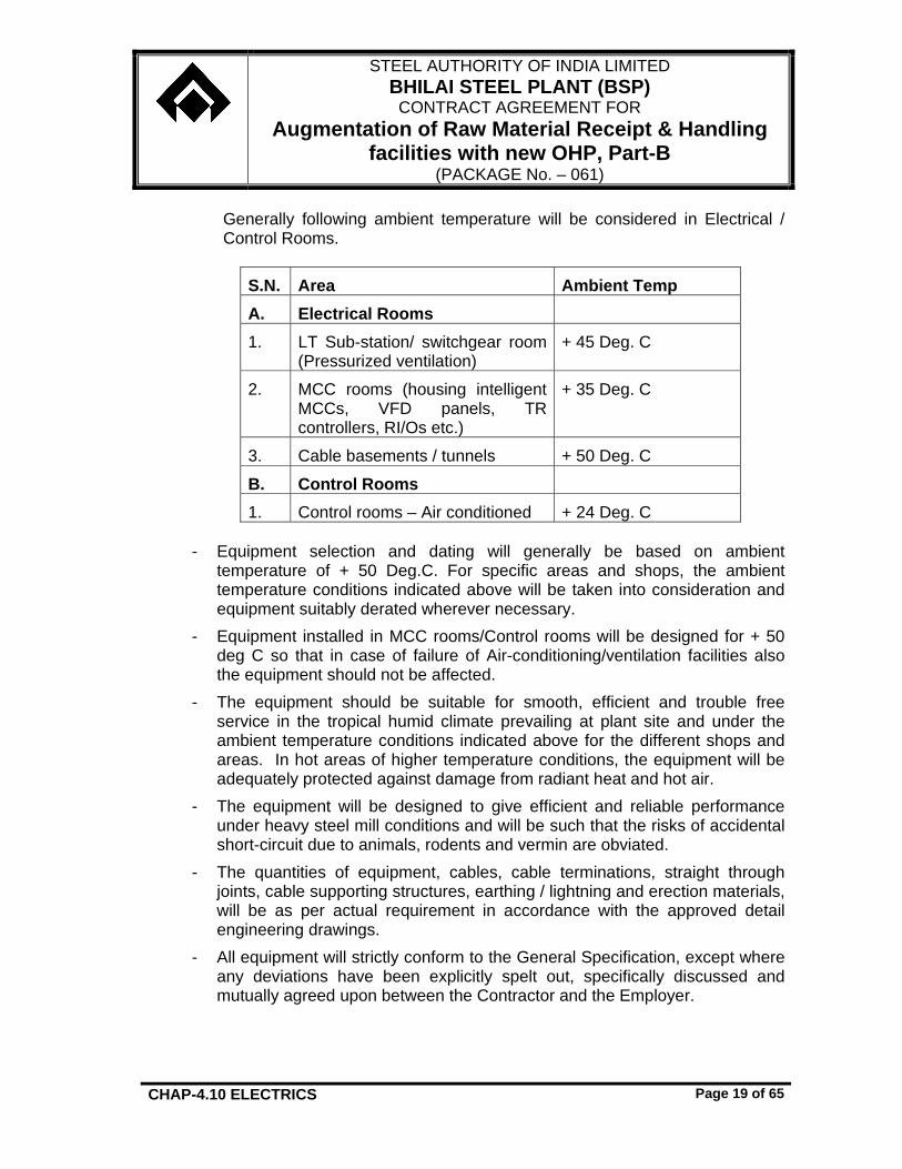
Generally following ambient temperature will be considered in Electrical / Control Rooms.
- Equipment selection and dating will generally be based on ambient temperature of + 50 Deg.C. For specific areas and shops, the ambient temperature conditions indicated above will be taken into consideration and equipment suitably derated wherever necessary.
- Equipment installed in MCC rooms/Control rooms will be designed for + 50 deg C so that in case of failure of Air-conditioning/ventilation facilities also the equipment should not be affected.
- The equipment should be suitable for smooth, efficient and trouble free service in the tropical humid climate prevailing at plant site and under the ambient temperature conditions indicated above for the different shops and areas. In hot areas of higher temperature conditions, the equipment will be adequately protected against damage from radiant heat and hot air.
- The equipment will be designed to give efficient and reliable performance under heavy steel mill conditions and will be such that the risks of accidental short-circuit due to animals, rodents and vermin are obviated.
- The quantities of equipment, cables, cable terminations, straight through joints, cable supporting structures, earthing / lightning and erection materials, will be as per actual requirement in accordance with the approved detail engineering drawings.
- All equipment will strictly conform to the General Specification, except where any deviations have been explicitly spelt out, specifically discussed and mutually agreed upon between the Contractor and the Employer.
STEEL AUTHORITY OF INDIA LIMITED BHILAI STEEL PLANT (BSP)
CONTRACT AGREEMENT FOR Augmentation of Raw Material Receipt & Handling
facilities with new OHP, Part-B (PACKAGE No. – 061)
CHAP-4.10 ELECTRICS Page 20 of 65
- The detailed specification and schedule of quantities will be worked out based on the detailed engineering to be carried out by the Contractor, for complete and proper execution of the specified tasks.
- The final ratings of the circuit breakers, CTs, busbars will be adequate for the actual loads and considering the derating factors as substantiated by temperature rise test on the 415 V switchboards. All CT ratios / VA burdens, ranges of meters and instruments, types of relays and relay setting ranges will be submitted for Employer’s approval during detail engineering.
- All HT cables will be 11 kV (UE) grade of size 3x185 sq mm (min).
4.10.07 Design basis for Electrical Premises of Ore Handling Plant
GTS is to be referred for designing of electrical premises & layouts, selection of equipment and installation. In addition to this, following points will be considered.
- Motor Control Centre (MCC), RIO stations, PDB, MLDB etc. to be installed in various MCC rooms, will be provided near various shop/technological units.
- Wherever required, MCC rooms and LT substation rooms (including rooms for distribution transformers) can be combined with separation wall and independent entry for both LTSS and MCC rooms considering the location of Substation and shop unit. Each LTSS building will have store facility.
- No under ground cable basement to be provided below MCC buildings. - PLC, CPU panels, Operator panel / HMIs, Engg stations, UPS, UPS battery
will be located in the air-conditioned room in the control room floor. - For high rise buildings structural walkway will be provided for maintenance of
light fittings. 4.10.08 Design Basis for Illumination System
GTS is to be referred for designing of Illumination System, selection of equipment and installation. In addition to this, following points will be considered.
- Illumination levels of all units will be as indicated elsewhere in this specification.
- The maintenance factor for design of illumination level will be considered as 0.6 for all areas.
STEEL AUTHORITY OF INDIA LIMITED BHILAI STEEL PLANT (BSP)
CONTRACT AGREEMENT FOR Augmentation of Raw Material Receipt & Handling
facilities with new OHP, Part-B (PACKAGE No. – 061)
CHAP-4.10 ELECTRICS Page 21 of 65
- For arriving at utilization factor, manufacturer's recommendation will be followed.
- For Illumination of Track Hopper Inhaul & Outhaul area, 2 nos. High mast on each side will be provided. (100m on either side).
- For Illumination of Wagon tippler Inhaul & Outhaul area 2 nos. High mast on each side will be provided. (100m on either side).
- All rooms with false ceilings will be provided with recessed type decorative mirror optics fittings.
- All MCC Rooms will have lighting switches near doors. - All decorative type fittings will be mirror optics type. - All buildings will be provided with peripheral lighting. - The power factor of lighting system will be improved to 0.9 by providing in
built capacitors with individual light fittings. - Area, outdoor and peripheral lighting will be fed from separate LDB/SLDBs
having two modes of control - AUTO and Manual. Under AUTO mode lights will be automatically switched ON/OFF through timers where as in Manual mode, lights will be switched ON/OFF through local control station located in Despatcher/Control room. Selector switch for mode of control will be located on local control station.
- Lighting in conveyor gallery and junction houses (floors above ground) will be connected to separate lighting circuit and the same will be switched ON/OFF by PLC based control from HMI at Despatcher.
- Area lighting, wherever applicable, will be provided through 400W, HPSV flood light fittings mounted on lighting towers.
- Road lighting will be provided with 250W HPSV street light fittings. - Well glass light fittings will have threaded covers. - All the offices will be provided with ceiling fans. - For indoor lighting, outgoing feeders in MCB DBs will be 20A SPN MCBs.
Each feeder will not be loaded more than 2 kW. Incomer to MCB DB will be suitably rated heavy-duty switch and ELCB for detection of leakage current.
- For area and road lighting, 3 phase & neutral feeders may be used and accordingly suitably rated 4 core cables may be provided.
- HPSV lamp fittings will be provided with external electronic igniters and a built in sensor to sense failure of lamp and switch off igniters.
- Single phase/three phase circuits are connected to RYB phase such that total connected load to each phase equal and phase balancing is achieved.
STEEL AUTHORITY OF INDIA LIMITED BHILAI STEEL PLANT (BSP)
CONTRACT AGREEMENT FOR Augmentation of Raw Material Receipt & Handling
facilities with new OHP, Part-B (PACKAGE No. – 061)
CHAP-4.10 ELECTRICS Page 22 of 65
- Stroboscopic effect will be corrected by providing power factor improvement capacitor and power phase distribution.
- Point wiring will be done through PVC insulated PVC sheathed copper cable. Minimum 6 sq.mm aluminum cable for 15A socket outlet and min. 4 sq.mm cable for lighting circuit will be considered.
- Single phase 3 pin 230V, 15A and 5A, switch-socket outlets will be provided with interlocked switches (male and female units) at the following locations:
o At each floor of building at every 30 m intervals or minimum one for
each row/side. o Two numbers each in switch gear room, cable basement, control
room and MCC room.
- Group control and sectorial control will be envisaged through MCBs provided in the respective LDBS. Separate control switches will be envisaged for light points and fan points.
- Near every chute in Junction houses and other technological buildings 24V,
5A sockets will be provided for maintenance lighting by hand lamp.
4.10.09 Cable Routes, Cables
Contractor will note the following requirements.
Sl. No.
Requirement Remarks
1. Inter shop cable routing Through overhead cable bridge/ structure/Cable Tunnel/ Conveyor gallery.
2. Bottom most level of cable trench in MCC room
Above ground level
4.10.10 Control and Operational Requirement:
1. All the necessary controls, interlocks and annunciation as required for smooth, efficient and safe operation of the plant will be provided.
2. Contractor will provide suitable PLC based automation system including all hardwares and softwares to run the existing and new material handling plant in an integrated manner.
STEEL AUTHORITY OF INDIA LIMITED BHILAI STEEL PLANT (BSP)
CONTRACT AGREEMENT FOR Augmentation of Raw Material Receipt & Handling
facilities with new OHP, Part-B (PACKAGE No. – 061)
CHAP-4.10 ELECTRICS Page 23 of 65
For integrating the existing drives of Ore Handling Plant and priority conveying route system for Sinter Plant, Junction House-27/JH-42 etc. in the new PLC based automation system, the existing 5-60/5-80 series PLC of M/s Rockwell make (located at Despatcher D1 & D2) will be upgraded by replacement of Processor, communication cards etc. to make it compatible with new PLC system retaining the existing RI/O panels and hardware. Quantam series PLC (of M/s L&T make) located at exiting Despatcher-D3 near JH-27. For integration of OHP (Part-A) being arranged by the Employer through a separate package, suitable gate way will be provided in the automation network. Integration and interfacing will be done to run the entire ore handling plant and Priority Conveying route system in an integrated manner. Automation configuration diagram is enclosed to refer in this regard.
3. All HT drives will be provided with extensive monitoring facilities for fault
detection and alarm annunciation. Alarm annunciation will be provided for over winding temperature, over bearing temperature, overload etc.
4. Alarm annunciation system will cover all the equipment of the electrical system.
5. Mode of control :
i) Plant will have four modes of control.
• Local de-interlock mode for control of individual drive motor from local push button station (LCS).
• Local interlock mode for running the drive motor in sequence interlock mode from LCS.
• REMOTE interlocked individual drive control from the HMI at Dispatcher/ Control room.
• REMOTE interlocked route wise control of conveying system from the HMI at Dispatcher/ Control room.
ii) Mechanism selector switch for selection of above modes of operation of
each drive motor will be provided in the MCC / Control Panel / DFP. A selector switch box will be provided near respective Remote I/O station for HT motors. Local selection of any drive will be shown on the HMI screen with some sort of caution.
STEEL AUTHORITY OF INDIA LIMITED BHILAI STEEL PLANT (BSP)
CONTRACT AGREEMENT FOR Augmentation of Raw Material Receipt & Handling
facilities with new OHP, Part-B (PACKAGE No. – 061)
CHAP-4.10 ELECTRICS Page 24 of 65
iii) The local de-interlock mode is meant for testing and maintenance
purpose only. However, all safety interlocks (Pull Chord Switches, motor Over Load & emergency stop etc.) will be connected in LOCAL de-interlock mode of operation. In local de-interlock mode the mechanism is not interlocked with other drive and after receive of permission from operator / PLC, drive / equipment can be started from LCS independently. The stop P.B. of local control station will be able to stop the drive mechanism selected for any mode of control. Hooter PB will be provided in LCS for pre start warning.
iv) In Local interlock mode the drive / equipment can be run in sequence interlock from LCS. Selector switch will be put in local interlocked position and permission from operator / PLC will be a condition for operation in this mode. Start, stop, motor Over Load, emergency stop, Pull Chord and Belt Sway Switches, Zero Speed Switch, chute jamming switches will be connected in the circuit in addition to sequence interlock with successive drives. All the above will be connected through hardwire.
v) In Remote interlocked individual mode of control the drives/ mechanisms in the material flow path will be started in succession sequentially opposite to direction of material movement from operating station / HMI. On tripping of any conveyor/drive/ mechanism, all the mechanisms feeding to the affected (tripped) mechanisms will stop according to material flow diagram. All the mechanism selector switches of the selected material flow path will be set to REMOTE position in this case. Programmable Logic controller will be used for the control, interlocking, operation, and monitoring of the equipment.
vi) In Remote interlocked Route-wise control, following operations is to be carried out from HMI by the operator before starting of a conveying route.: a) Selection of material flow path including source and destination
as per requirement. b) Selection of mechanisms within the selected material flow path. c) Selection of switching devices, flap gate etc. in a conveying route d) Selection of control mode in REMOTE of master selector switch
for each material flow path block chain. On receiving start permissive signal from HMI, the operator will give ON command to start the desired conveying route.
STEEL AUTHORITY OF INDIA LIMITED BHILAI STEEL PLANT (BSP)
CONTRACT AGREEMENT FOR Augmentation of Raw Material Receipt & Handling
facilities with new OHP, Part-B (PACKAGE No. – 061)
CHAP-4.10 ELECTRICS Page 25 of 65
vii) Normal stop and Emergency stop of mechanism for each material flow
path, P.B, switches for pre-start warning signal for each material flow path, start & stop P.B. switches of drives with independent operation etc. will also be mounted on desk/ HMI.
viii) A pre-start audio warning signal through motorised hooters will be given in the premises where the mechanisms are to be started before start of the mechanism. The duration of the pre-start audio signal will be as per requirement. Sequential start of the mechanism will be possible only after the pre-start audio signal is over.
ix) The conveying system will be integrated with the associated auxiliary / other system for interlocking, sequencing and monitoring.
x) Stopping of mechanisms : a) For regular stop, the feeding equipment will be stopped first to stop the
material flow in the conveying path and then after some time delay the equipment in the route will be stopped in sequence from feeding end ensuring no material is in the conveying path.
b) Emergency stop push button will be provided on the Control desk for emergency stop of material flow path.
c) In case of tripping due to fault of any drive, the part of the conveying route before the faulty drive will stop. There will have signaling of the stopped mechanisms by changing colour in the graphic. This will give an indication of the fault.
6. Signaling : A) Status of ON, OFF, Trip/Fault ,Route selection etc. for all mechanisms
of conveying system, dedusting system, dust suppression system, weigh feeder etc. will be available in the operator work station.
B) When a drive in a conveying route is shifted to local controls, indication will be available in the HMI.
C) The annunciation will be provided on HMI for each drive fault and actuation of safety and limit switches. a) Annunciation for O/L & fault of each drive motor. b) Individual annunciation for all HT motors trip due to high bearings
and winding temperature.
STEEL AUTHORITY OF INDIA LIMITED BHILAI STEEL PLANT (BSP)
CONTRACT AGREEMENT FOR Augmentation of Raw Material Receipt & Handling
facilities with new OHP, Part-B (PACKAGE No. – 061)
CHAP-4.10 ELECTRICS Page 26 of 65
c) Combined fault HT switch gear for Each HT motor including power supply to MPR failure separately.
e) Switching devices, flaps etc failed to close or open. f) Individual annunciation for HT motors bearings and winding
temperature high alarm. g) Individual annunciation for following conditions of electrical
- Transformer trouble alarm. - Combined fault/trouble in bag filter system of D.E - Unhealthiness of various machines - Any other failures
h) Every unplanned stoppage or abnormal condition will be brought to the notice of operator.
7. Current readings of all HT and LT motors connected to Intelligent MCC will be available in HMI at Dispatcher.
8. Drainage / sump / slurry pumps will be provided with Auto/Local mode of operation. Under automatic mode of operation any one of the pump motors will start automatically at set level and if the level rises further the second/ reserve pump will start automatically at second set level and both the pumps will stop at set low level. If the first pump trips, second pump will start automatically. Emergency high level annunciation will be available in the control room. Under local mode of operation, the pump motors will start/stop locally through local control boxes depending on level.
9 For fire fighting system, suitable control system will be provided for main fire water pump, jockey pump, hydro pneumatic tank etc. with line pressure switch.
4.10.11 ELECTRICS AND AUTOMATION FOR EXISTING DRIVES Scope of work for Electrics and Automation will be as follow for
upgradation / modification and integration of existing conveyors / equipment :
For Reversible Shuttle Conveyor J9B-RSC1 :
STEEL AUTHORITY OF INDIA LIMITED BHILAI STEEL PLANT (BSP)
CONTRACT AGREEMENT FOR Augmentation of Raw Material Receipt & Handling
facilities with new OHP, Part-B (PACKAGE No. – 061)
CHAP-4.10 ELECTRICS Page 27 of 65
• Contractor will dismantle existing motor, Festoon Cable trolley
system, associated power and control cables, related to the particular drives and replaced by the new drives / Plastic Cable Carriage system for power and control trailing cables and associated cables.
• Supply and installation of new Limit switches for additional feeding points.
• Necessary cabling for additional feeding point. • Existing feeders of the MCC will be modified by the replacement of
the relays, components etc. to match with the upgraded drives. • Scheme and Software modification for selection and feeding of
additional points. The approval / clearance of BSP / their representative will be taken before carrying out new installation for upgradation / modification for existing conveyors / equipment. For the Employer’s approval / clearance, Contractor will submit detailed shut down plan of the existing drives indicating temporary arrangement to be made by the Contractor for running suitable alternative conveying routes so that plant can maintain production level. In the temporary arrangement in case any electrics is required, the same will be provided by the Contractor without any price implication.
List of Existing Conveyors controlled from MCC and PLC/ RI/O Panels : Details of existing drives with MCC No. / RI/O Panels and their location are as indicated below. Further details , if any ,will be furnished during detailed engineering stage.
STEEL AUTHORITY OF INDIA LIMITED BHILAI STEEL PLANT (BSP)
CONTRACT AGREEMENT FOR Augmentation of Raw Material Receipt & Handling
facilities with new OHP, Part-B (PACKAGE No. – 061)
CHAP-4.10 ELECTRICS Page 28 of 65
4.10.12 TECHNICAL SPECIFICATION 4.10.12.1 General
GTS will be referred for technical specification of various electrical equipment. However for specific application following TS will be considered.
4.10.12.2 Wagon Tippler and Side Arm Charger
01 Variable Voltage Variable Frequency Converters (AC Drives):
AC drives will have communication facility with PLCs for data transfer and speed reference set point.
Software of AC drives will be developed in such a way that after over voltage or under voltage when the drive trips, the AC drive will be automatically resetted without any manual intervention after normalising of the voltage.
Remaining features will conform to General Technical Specification (GTS).
02 Programmable Logic Controller (PLC) :
- The system will be complete with CPU, I/O racks, memory, key board and monitor. HMI will depict graphics of various mechanism operations and also provide alarm annunciation system. Spare CPU with loaded software will be installed in the PLC panel.
- Communication between PLC and AC drive will be possible for smooth
operation of the Tippler. PLC will have facility to communicate with Despatcher-D1 / Central Control room PLC. All the required hardware and software for these communications will be provided.
- PLC will perform the following task :
Logic interlock functions, control & supervision of drives &
solenoid valves. Automatic sequential operation of various drives. Status indication & signaling. Fault monitoring & annunciation. Diagnostic features to recognise and display faults.
STEEL AUTHORITY OF INDIA LIMITED BHILAI STEEL PLANT (BSP)
CONTRACT AGREEMENT FOR Augmentation of Raw Material Receipt & Handling
facilities with new OHP, Part-B (PACKAGE No. – 061)
CHAP-4.10 ELECTRICS Page 29 of 65
Communicate with Despatcher-D1 / Central Control room PLC.
- Remaining features will conform to General Technical Specification (GTS).
03 Control Desk :
• Control desk will be provided for centralised control, monitoring of all the drives of Wagon tippler and SAC, including annunciations of all the faults, over-load trip condition of drives, failure of safety devices, all faulty conditions, warning conditions, over/under positioning conditions, over travel conditions etc. Separate and independent annunciation for each will be provided instead of group annunciation.
• Control desk will have suitable nos. of status indication lamps to cover complete dust suppression system, SAC positions & movements including arm positions etc. and also for down stream equipment of wagon tippler.
• A control desk will be provided also on the side Arm Charger . • Remaining features will conform to General Technical Specification
(GTS).
04 Weighing System : Microprocessor based weighing system will be provided. The load cell will be magneto – elastic type / strain gauge type, suitable for over load up to 300% of their nominal load. Minimum 4 (Four) numbers of load cells are to be provided at each weigh bridge integral with wagon tippler table. Accuracy of weighing system will be +/- 0.1% or better. For other features Specification for Belt scale will be referred.
Indicating cum data logging type weighbridge for weighing both loaded and empty wagon will be complete with PC based operating station in the wagon Tippler Control Room.
The supply will be complete with the following : Load cells, signal converters, PCs , 19” colour monitor, keyboard, mouse, etc.), original licensed operating software and application software, inkjet printer, UPS, control room furniture for installation of PCs, printers, power distribution boards, etc.
The capacity of the weigh bridge will be adequate to permit passing of 180 metric tones weight of shunting loco at the speed of 8 Km per hour.
STEEL AUTHORITY OF INDIA LIMITED BHILAI STEEL PLANT (BSP)
CONTRACT AGREEMENT FOR Augmentation of Raw Material Receipt & Handling
facilities with new OHP, Part-B (PACKAGE No. – 061)
CHAP-4.10 ELECTRICS Page 30 of 65
• Remaining features will conform to General Technical Specification
(GTS).
05 Control and Operational Requirement
• All drives and mechanisms will have Auto, Remote -interlocked mode and Local mode controls. Local controls will be provided and normally it will be used for maintenance and testing purpose only. Only safety interlocks will be covered in Local control. STOP push button of Local control will be able to stop the drive/mechanism selected for any mode of control.
• It will be possible to operate the side arm charger (SAC) both from
control panel located in the Operator cabin of SAC and Control desk located in the control room. Auto operation of SAC along with wagon tippler operation will be done from Control desk. SAC operation from its control box in the SAC operator cabin will be done as required after the receipt of instructions / permissive from control desk operator.
• Operation philosophy will be developed in such a way that normally
one operator will be required to operate the wagon tippler and SAC from wagon tippler control room and one helper near tippler table to de-couple the leading wagon from the rake. Emergency stop switch will be considered at WT and SAC in addition to control desk.
• The loaded wagon to be tippled will be decoupled manually from the
rest of the rake and the person doing the decoupling operation will press a switch installed near-by to indicate to control room that decoupling operation is complete. Subsequently, pulling of the wagon by SAC, placing it on wagon tippler, return of SAC to wagon rake for start of next cycle, tippling of wagon by wagon tippler etc. will start automatically in proper sequence.
• The SAC will pull and place the decoupled wagon over the tippler.
Once the wagon is placed on tippler deck and SAC clears the tippler deck, tippler will clamp the wagon, tipple it, return to its original position, declamp the wagon and other operations as required. The wagon vibrator will operate automatically, if selected for auto-mode when the wagon is in inverted position. The type of wagon being unloaded, identification of sick wagons etc. will be registered in Control desk by the control room operator.
STEEL AUTHORITY OF INDIA LIMITED BHILAI STEEL PLANT (BSP)
CONTRACT AGREEMENT FOR Augmentation of Raw Material Receipt & Handling
facilities with new OHP, Part-B (PACKAGE No. – 061)
CHAP-4.10 ELECTRICS Page 31 of 65
• The water spraying for dust suppression will start automatically when
wagon is being tippled and will stop when the tippler is not operating by establishing suitable interlocking between controls of wagon tippler and dedusting system.
• Each operational cycle will be repeated automatically till the last
wagon is tippled and removed from the tippler deck. The complete operation will be done in automatic sequentially interlocked manner and some of the activities will be parallel so that system can easily achieve a required tippling rate per hour.
• Positioning of Wagon Tippler and SAC will be through proximity
switches and backed-up by heavy duty rotary limit switches. All limit switches and proximity switches must work smoothly and without adjustment and mal-functions under severe conditions of vibrations. All rotary switch and limit switches should be mounted and housed with suitable vibration damping arrangement.
• Wagon counter will be provided with correction facility by authorized
person to account for sick wagons.
• Laser Beam sensors with transmitter and receiver at both ends of Wagon Tippler to ensure that no other wagon is in close proximity to the wagon tippler table.
4.10.12.3 Yard machines
01 HT VCB without Protection General Technical Specification (GTS) will be referred for detailed specification.
02 Cable Reeling Drum
a) For Yard Machines • Two cable reeling drums, one for power and other for control will be
provided on the machine. The cable reeling drum will be complete with stalled torque motors, suitable slip-rings and brush assembly, cable guides for proper paying in/paying off cables, cable layering arrangement, protection against over tension and under tension of cable, limit switches
STEEL AUTHORITY OF INDIA LIMITED BHILAI STEEL PLANT (BSP)
CONTRACT AGREEMENT FOR Augmentation of Raw Material Receipt & Handling
facilities with new OHP, Part-B (PACKAGE No. – 061)
CHAP-4.10 ELECTRICS Page 32 of 65
etc. The stalled torque motor may be of slip-ring induction type with rotor resistance steps automatically adjusted depending on the position of the machine and tension in the cable.
• The cable reeling drum will also be provided with gear cam limit switch,
pendulum limit switch, the directional limit switches etc. as necessary for the application. At least two spare turns of cable will be provided for each reeling drum. The traveling gear will stop when the next to last turn of cable is reached. Necessary limit switches will be provided for the same. The speed of the winding of cable will be properly matched with machine travel speed.
• The number of slip-rings for the power cable reeling drums will be four,
three for power and one for earth. The number of slip-rings for control reeling drum will be as per requirement keeping at least two as spare. Slip-ring & brush-gear assembly of cable reeling drums will have dust and weather proof enclosure having inspection window suitably located. The inspection window will be readily accessible.
• The enclosure of motor will be IP:55 as per IS:4691 and the motor will have
weather - proof construction.
• The cable reeling drum will be of substantial strong construction with components such as chain etc. selected for heavy duty applications.
• Flexible cable length and CRD will be adequate to take desired travel
length of machine and dead turn of cable. • To avoid damage of HT flexible cable during paying off from CRD a
structural arrangement beside rail / yard conveyor will be provided to place the CRD cable. Arrangement will be such that cable will be pay off on the guided structural platform installed at one side of yard conveyor.
b) TS of CRD in Tripper car, Paddle feeders and other mobile machines will
be as above.
03 Variable Voltage Variable Frequency Converters (AC Drives):
• Long Travel for Yard Machine will be through VVVF drive. Separate VVVF drive will be provided for Right & Left side of drive. Each VVVF drive will have capacity to run all travel drives in case of emergency.
STEEL AUTHORITY OF INDIA LIMITED BHILAI STEEL PLANT (BSP)
CONTRACT AGREEMENT FOR Augmentation of Raw Material Receipt & Handling
facilities with new OHP, Part-B (PACKAGE No. – 061)
CHAP-4.10 ELECTRICS Page 33 of 65
• AC drives will have communication facility with PLCs for data transfer and speed reference set point.
• Software of AC drives will be developed in such a way that after over voltage or under voltage when the drive trips, the AC drive will be automatically resetted without any manual intervention after normalising of the voltage.
• AC drive panels will be mounted on anti vibration pads • Remaining features will conform to General Technical Specification (GTS).
04 Programmable Logic Controller (PLC) :
• Each machine will be provided with PLC and HMI. The system will be complete with CPU, I/O racks, memory, key board and monitor. HMI will depict graphics of various mechanism operations and also provide alarm annunciation system. Spare CPU with loaded software will be installed in the PLC panel.
• Communication between PLC and AC drive will be possible for smooth
operation of the machine.
• PLC will have facility to communicate with PLC at Despatchers / central control room / HMI through radio communication and also hardware communication by CRD control cable. All the required hardware and software for radio communication will be provided.
• Minimum 2 nos. field programmer for yard machines will be provided.
• PLC will perform the following task :
Logic interlock functions, control & supervision of drives &
solenoid valves. Automatic sequential operation of various drives/ devices. Status indication & signaling. Fault monitoring & annunciation. Diagnostic features based on logical rules to recognise and
display faults. Communicate with respective Despatchers / Central Control
room.
• PLC panels will be mounted on anti vibration pads.
STEEL AUTHORITY OF INDIA LIMITED BHILAI STEEL PLANT (BSP)
CONTRACT AGREEMENT FOR Augmentation of Raw Material Receipt & Handling
facilities with new OHP, Part-B (PACKAGE No. – 061)
CHAP-4.10 ELECTRICS Page 34 of 65
• Remaining features will conform to General Technical Specification (GTS).
05 Control Desk
Control desk in operator's cabin will contain :
• Machine power 'ON' lockable push button and indication lights. • Machine control 'ON' push button and indication lights. • Selector switches for various sequences. • Push buttons and indicator lights required for auxiliaries control. • Master controllers will be provided as required. • Inductive type master controller will be provided for VVVF controlled
drive. • Ammeters will be provided. • Monitor & key board of HMI system and printer. • The monitor of HMI system will depict the required graphics.
06 Control modes 1. Local de-interlocked mode operation from Local control station mounted
near the drives and the same will be generally used for testing. 2. Remote mode from Control Desk :
All the drives will be controlled from control desk located in the operator's cabin. Robust industrial type hooters & sirens will be ON before starting of machine.
Following types of sequence control will be provided.
A. Semi-automatic operation
• Different process sequence will be automatic. Progress of a sequence will depend on limit switches or sensors corresponding to different positions.
• Each sequence will be controlled from control desk by push button/ HMI
key board. • A sequence will start only when all the preconditions and permanent
requirements including healthiness of drives and circuit are met.
STEEL AUTHORITY OF INDIA LIMITED BHILAI STEEL PLANT (BSP)
CONTRACT AGREEMENT FOR Augmentation of Raw Material Receipt & Handling
facilities with new OHP, Part-B (PACKAGE No. – 061)
CHAP-4.10 ELECTRICS Page 35 of 65
• It will be possible to switchover to interlocked step-by-step mode during
the operation of the sequence.
B. Interlocked step-by-step operation
• Each sub-sequence of the main sequence will be controlled from control desk by separate push button / key board.
• The progress of sub-sequence will depend on the limit switch position
or sensors. • Each movement will be started only after ensuring the necessary
interlocks. • The progress of each sub-sequence will be displayed on the control
desk and monitor of HMI. • It will be possible to switchover to semi-automatic mode only after the
completion of a sequence.
C. Annunciation and indications
An alarm will be available in case of any fault. An acknowledge push button and the fault display will also be provided.
Annunciation will be provided for all faulty condition including interlocking failure, safety system failure and abnormal condition like emergency tripping, failure of all drives, rail clamp not fully open, boom position low, over tension, slackness, fully unwound conditions for CRD’s, transformer over load, temperature high, hoisting alarm limits for boom, wind pressure high, hydraulic system failure etc.
07 Special Requirement
CRD (power & control) will be provided with declutching arrangement in the cable guide mechanism for easy adjustment of cable guide. • Suitable structure beside yard conveyor to place the flexible cable
during paying off from CRD. • Layer counter will be provided for Stacker to count nos. of layers. • Angular position of the boom of Stacker will be displayed in the
Stacker cabin. • All yard machines will have facility to control from operator cabin and
also from Despatcher / Control Room. Normally operator desk in cabin will be used. Necessary radio communication between yard
STEEL AUTHORITY OF INDIA LIMITED BHILAI STEEL PLANT (BSP)
CONTRACT AGREEMENT FOR Augmentation of Raw Material Receipt & Handling
facilities with new OHP, Part-B (PACKAGE No. – 061)
CHAP-4.10 ELECTRICS Page 36 of 65
machines and control room will be considered. • Over speed protection will be provided for long travel of Stacker. • Suitable overground structure at one side of the yard conveyor to
place the flexible cable during paying off from CRD. Both CRD will be on one side of yard conveyor.
• Separate brake panel will be provided for individual motor in all yard machine.
• For all yard machines provision of 6.6 kV junction boxes will be made for connections in line with existing practice. This junction box gets supply from the ground isolator of the machine.
01 The motor will be 3 phase squirrel cage TEFC class F insulated (temperature rise limited to 70 deg. C. over an ambient of 50 deg. C), IP-55 enclosure both for motor switches & its terminal box, and with high starting torque and high stalling torque. The duty cycle will be S2-10 min or S4/ S5-1200 cycles per hour or S4/ S5-600 cycles per hour depending upon the rating and application of the actuator.
02 Each actuator will be provided with extremely dependable both 'Open' and 'Close' torque and position limit switches. The torque and limit switches will be provided with suitable means like mechanical selection, end position latching etc. for easily and accurately setting at required end position. The torque switch should not unnecessarily trip during initial unseating Hammer blow effect. The anti-hammer feature of the torque switch latch will be available throughout travel including at end positions. Once the torque switch has tripped in either direction, it can only be reset by operation of the actuator in the opposite direction. Each switch will have 2 NO + 2 NC potential free double break contacts. Switch contact ratings on inductive circuits will be 5A AC at 230 V AC.
Actuator will be provided with motor over-riding feature like hand wheel for emergency manual operation and a limit switch will be provided which contacts will be used in the motor control circuit to forbid the motorised operation during manual operation by hand wheel. Also when the motor is switched 'ON' the hand wheel connection will be disengaged automatically. Motor operation will always have priority over manual operation.
STEEL AUTHORITY OF INDIA LIMITED BHILAI STEEL PLANT (BSP)
CONTRACT AGREEMENT FOR Augmentation of Raw Material Receipt & Handling
facilities with new OHP, Part-B (PACKAGE No. – 061)
CHAP-4.10 ELECTRICS Page 37 of 65
Internal wiring will be tropical grade PVC insulated, stranded copper conductor cable of 10A rating for control circuits and required ratings for motor. All wires will be clearly numbered at both the terminal block and component ends. The voltage grade of cables/ wires will be 1100V. Power terminals will be separated from the control terminals by means of an insulating cover. Separate terminal block fitted to switching unit will be provided. The terminal box will be designed for the protection class or IP-65. A durable terminal identification card showing plan or terminals will be provided attached to the inside of the terminal box cover indicating serial number, external voltage values, wiring diagram number and terminal layout.
The actuator will be suitable for operation at specified ambient temperature. All actuators will be neoprene O-ring sealed water tight and dust proof to IP-67 protection and will at the same time have an inner watertight neoprene O-ring seal between the terminal box and the internal electrical elements of the actuator, fully protecting the switch mechanism, motor and all other internal electrical elements of the actuator from ingress of moisture and dust when the terminal box cover is removed on site for cabling/ maintenance.
The actuators will be operated from the Remote Control Station and Local control station (LCS) will be provided separately for local operation of the actuator for testing and maintenance purpose. Isolator along with starter for the actuator motor will be located in the Contractor's MCC. Separate power cable will be used for motor wiring.
4.10.12.5 Belt Weigh Feeders
General Technical Specification (GTS) will be referred for detailed specification of Belt Weigh Feeders.
4.10.12.6 Belt Weigh Scales
General Technical Specification (GTS) will be referred for detailed specification of Belt Weigh Scale.
4.10.12.7 Suspended Electromagnet/ ILMS
The magnet will be of high permeability cast steel as per IS : 4491 with an integral terminal box of adequate size. Leads will be brought to the terminal box through a water tight sealed gland. An earthing terminal will be provided inside the terminal box. The coil of the magnet will be
STEEL AUTHORITY OF INDIA LIMITED BHILAI STEEL PLANT (BSP)
CONTRACT AGREEMENT FOR Augmentation of Raw Material Receipt & Handling
facilities with new OHP, Part-B (PACKAGE No. – 061)
CHAP-4.10 ELECTRICS Page 38 of 65
designed for continuous duty for full supply voltage. The magnet will be fed from 220V DC obtained through rectifier panels.
The magnet coil will be Fiber glass wound copper wire and class H insulation will be used.
Control panel will be free standing, floor mounted, front attended, made of CRCA sheet steel of thickness not less than 2mm with IP54 enclosure class. In-comer feeder will have load break switch interlocked with the door.
Panel will have air cooled control transformer, full wave, silicon diode Rectifier Bridge having 220V DC output and complete with RC circuit across each diode, PIV of diode will not be less than 1560V.
Complete safety and protection equipment against surge voltages, discharge resistance in DC load side will be provided. Electronic temperature sensing circuits for protection against excessive temperature in the magnet coil will also be provided.
For In Line Magnetic Separator necessary electrics will be included.
4.10.12.8 Dust Suppression System
Control Panel for DS system will have necessary starter for Pump motors and 24V DC power supply arrangement for Solenoid valves. Valves will be energised either by Local Push button station or by under belt switch depend upon selection of control mode. Necessary electrics will be provided for desired operation of pumps, compressors, valves etc. for DS system. DS system will be interlocked with corresponding conveyors / technological equipment. DS system will have local manual and remote auto mode control. Compressor may be connected to nearest MCC considering location of Compressor house.
4.10.12.9 DUST EXTRACTION SYSTEM
The Dust Extraction System will be started first and will be suitably interlocked with corresponding conveyors / technological equipment. The equipment of D.E. system will be operated in sequence as per requirement in the REMOTE mode from the HMI. Power supply to bag filter panel will be interlocked with the DE fan. Bypass arrangement will be provided such that technological equipment may be operated without operation of DE system in case need arises.
STEEL AUTHORITY OF INDIA LIMITED BHILAI STEEL PLANT (BSP)
CONTRACT AGREEMENT FOR Augmentation of Raw Material Receipt & Handling
facilities with new OHP, Part-B (PACKAGE No. – 061)
CHAP-4.10 ELECTRICS Page 39 of 65
Electrics for Bag Filter System of DE System.
The bag filters of D.E. system will consist of pressure switches cum indicator in the compressed air line, differential pressure switches, solenoid valves, control panel and all other associated equipment. The brief specification of the major components will be as given below:
01 Control panel for Bag filter
The control panel will be free standing floor mounting fabricated from 2.5 mm thick CRCA sheet steel on a base channel or 250 mm height provided with cable gland plates, having synthetic rubber gasketting provided with double door & canopy and enclosure conforming to IP-55. The control panel will be factory assembled, wired with 1.1 kV grade PVC flexible wire of copper conductor (minimum size 2.5 sq.mm), factory painted. The control panel will be provided with following major equipment : b) Incoming switch (minimum 30A, AC23 duty) with operating handle
inter-locked with the door, HRC fuses, contactors, MCBs in the various circuits.
c) Control transformer or required VA rating having +/-5 percent and +/- 2.5 percent tapings in the primary side of the control transformer with Isolating switches/ MCBs in the primary & secondary sides.
c) 24V DC power pack complete with fitter and protective elements and also isolation cum short circuit protection both at AC and DC sides for power supply to solenoid valves.
d) Auxiliary contactor for control power supply monitoring interlocking, and controls etc.
e) Auto-manual selector switches, push button switches, indication lamps, various monitoring devices, terminals (with 20 percent spare terminals) and other circuit elements required for control and monitoring
f) Solid State Bag filter timers.
02 The bag filter timer will be solid state device suitable for dusty, tropical and specified aggressive environment. The bag filter- timer will be provided with internal semi-conductor fuse protection and will have provision for pulse frequency setting and pulse duration setting through independent operating knobs. The number of contacts in the timer will
STEEL AUTHORITY OF INDIA LIMITED BHILAI STEEL PLANT (BSP)
CONTRACT AGREEMENT FOR Augmentation of Raw Material Receipt & Handling
facilities with new OHP, Part-B (PACKAGE No. – 061)
CHAP-4.10 ELECTRICS Page 40 of 65
be equal to number of solenoid operated valves so that the timer will energise only one solenoid valve at a time.
03 The Bag Fitter Timer will provide timed sequential energisation of 24V DC operated solenoid valves of bag filters LEDs for each solenoid energisation. Power ON in PCB feed back relay will be provided with potential free contacts which will close under following conditions: a. Fault in the PCB.
ii) Open contact in the output side connected to individual solenoid valves. The contact will not close in the event of power failure to the controller.
iii) The sequential control (i.e. process) will start when the Differential Pressure (DP) switch is actuated at the first set point for normal operation. The process will continue till the pressure differential drops below the set value. When again the DP switch is actuated the process will continue from the previous position (i.e. next solenoid valve). However, when the power supply to sequential controller trips, the process will stop and sequential controller is reset to first load position enabling the process to start from the beginning.
iv) Sufficient space will be provided for installation of bag filter panel with required front clearances for operation and maintenance including side and back clearances as required.
04 Differential Pressure Switch i) The differential pressure switch will have two sets of independent
micro switches. The first set will be used for normal sequential cleaning operation of the bag filters as per lower set value of differential pressure. This set point will be independently adjustable.
ii) The second set of N.O. contact will close at upper set value of differential pressure representing clogging condition of bag filter and will be used for signaling and monitoring. This set point will also be independently adjustable. The contacts will be rated for 5 Amp, 240V AC.
iii) The DP switch will be suitable for outdoor installation. The DP switch casing will be made of pressure die cast Aluminium with enclosure conforming to IP-65.
iv) One number differential pressure switch with two set points will
STEEL AUTHORITY OF INDIA LIMITED BHILAI STEEL PLANT (BSP)
CONTRACT AGREEMENT FOR Augmentation of Raw Material Receipt & Handling
facilities with new OHP, Part-B (PACKAGE No. – 061)
CHAP-4.10 ELECTRICS Page 41 of 65
be provided for each module of the Bag filter. Alternatively, two numbers of DP switches may be provided for each module one for initiation of bag cleaning operation and other for signaling and monitoring of clogging condition.
05 Solenoids
The solenoid coil will have encapsulated coil (class 'F' insulated with a water proof (IP-65) plug-on connector. The coil will be suitable for 24V DC. The coil will be made of copper conductor.
06 Air Pressure Switch cum indicator
One number compressed air pressure switch cum indicator will be provided for each DE system in the incoming compressed air pipe line of the bag filter. The pressure range will match with the operating pressure. The switches will be snap action type with 1 NO + 1 NC contacts of SA, 230 V AC. These contacts will be wired up to terminals in the bag filter control panel. The enclosure of the air pressure switch will be pressure die cast aluminium conforming to IP-55.
4.10.12 Type of Light Fittings and Illumination Levels
Illumination level and light fittings will be provided for different units as indicated below :
SL. NO.
UNITS ILLUMINATION LEVEL (LUX)
TYPE OF LIGHT FITTINGS
1. Electrical rooms, substations, MCC Rooms etc.
200 Trough type, 2x40W, fluorescent tube light fittings with reflectors.
2 Junction Houses and Conveyor Galleries / tunnels
100 70W/150W, HPSV, well glass fittings and 250W High bay as required.
3 Crusher house, other process and Technological Building
150 70W/150W, HPSV, well glass fittings and 250W High bay fitting as required
12. Area and road lighting 15 Flood light fittings with250 / 400W, HPSV Lamp and Street light fittings with 250W, HPSV Lamp.
Number of light fittings will be decided on the basis of specified lux level, maintenance factor 0.6 and appropriate co-efficient of utilization as per manufacturer's recommendation.
4.10.13 DRAWINGS AND DOCUMENTS
Contractor’s scope of work for all design drawings and documents will be as given below. The Contractor will submit a list of all drawings and documents he proposes to submit within 2 weeks of LOI. The list will be approved by Client / MECON and may be modified if necessary. Each
STEEL AUTHORITY OF INDIA LIMITED BHILAI STEEL PLANT (BSP)
CONTRACT AGREEMENT FOR Augmentation of Raw Material Receipt & Handling
facilities with new OHP, Part-B (PACKAGE No. – 061)
CHAP-4.10 ELECTRICS Page 43 of 65
drawing/documents in the list will be identified with a serial number, description and scheduled date of submission. Contractor will also furnish soft copies of all the drawings indicated below and drawings of technological layout/units. All design, engineering and manufacturing drawings will be required to be approved by Employer/Consultant. Work will be carried out exactly as indicated on the approved drawings and specification. No alterations will be made without prior written approval by Employer / his consultant. The Contractor will check all the drawings prepared by them and/or received from their vendors/supplier/sub-supplier and satisfy themselves about the correctness of drawings before issuing to Employer / Consultant. After checking, properly stamped drawings will be sent to Employer/Consultant for approval / clearance. Comments on all drawings will be forwarded to the Contractor for incorporation and resubmission. The approval of drawings by Employer or their authorised representative does not absolve or relieve the supplier from any of his obligations under this contract and he will be wholly and solely responsible for the satisfactory operation and guaranteed performance of equipment / system / plant.
A. Basic Engineering drawings (To be Submitted For Approval in 6 sets)
1. List of drawings (Basic Engg /Detailed Engg/ Reference) and
drawing numbering system along with schedule of submission.
2. Single line diagrams of MCCs /Control Panels, PDBs, MLDBs, LDBs, SLDBs, Main fire detection and alarm panel etc. with rating of components, cable sizes and details of protection and metering etc.
3. HT & LT Motor and component list including field mounted electrics
4. HT and LT Motor data sheets as per enclosed format.
5. Type-II Co-ordination chart as per IS: 13947-1993 for MPCB/ MCCB, Contactor and Overload relay.
6. Schematic drawing of different feeders, control, alarm, indications, interlocking and other schematics.
7. Shop/Unit wise Maximum Demand calculations
STEEL AUTHORITY OF INDIA LIMITED BHILAI STEEL PLANT (BSP)
CONTRACT AGREEMENT FOR Augmentation of Raw Material Receipt & Handling
facilities with new OHP, Part-B (PACKAGE No. – 061)
CHAP-4.10 ELECTRICS Page 44 of 65
8. Relay settings with calculations for total network to ensure proper co-ordination.
9. Busbars sizing calculation with respect to temperature rise & short circuit withstand capacity.
10. Design Calculations for selection of main equipment such as transformers drive motors, AC drives, bus bars, cables, batteries etc.
11. Typical schemes of DOL, RDOL feeders indicating inputs & outputs applicable to the various feeders indicated in SLDs.
12. Power and regulation schemes of AC drives.
13. Calculation for temperature rise of busbars.
14. Layout of substations, electrical rooms and control rooms including ventilation and air-conditioning rooms, handling facilities. The layout drawings indicating cable trench, wall openings, conduit inserts, plate inserts, Minimum clearances from electrical panels for installation of panels, cable trays, conduits for concealed wiring etc.
15. Electrical Equipment Layout of all electrical rooms, control rooms indicating panel dimensions, space available for future expansion with building dimensions.
16. General arrangement of equipment with plan, front view and sectional views, comprehensive bill of materials with description, quantity, make and type.
17. Cable layout drawings in cable tunnel, cable channels, overhead cable structures/bridge and incoming cable route etc.
18. Interplant cable route drawings.
19. Type tests certificates of all major equipment like transformers, switchgear etc.
20. Level-1 automation system configuration & I/O lists, Belt Scale, Belt Weigh feeder, UPS & VVVF single line diagrams.
21. Functional description, control philosophy for the plant indicating start up, shut down, control locations, interlocking and annunciation system, mimic pages, report/data formats (for reference).
22. Scheme for Illumination system & emergency lighting system indicating sizes, ratings & locations of various LDBs & SLDBs.
STEEL AUTHORITY OF INDIA LIMITED BHILAI STEEL PLANT (BSP)
CONTRACT AGREEMENT FOR Augmentation of Raw Material Receipt & Handling
facilities with new OHP, Part-B (PACKAGE No. – 061)
CHAP-4.10 ELECTRICS Page 45 of 65
23. Tentative Dimensions of panels.
24. Earthing and lightning protection scheme and layout of earthing and lightning protection network with calculations.
25. Quality assurance plan for various electrical equipment.
B. Detailed engineering drawings. (To be Submitted For Approval in 6 sets)
1. Civil/Structural engineering design drawings of Electrical buildings,
Electrical rooms, Control rooms, Motor foundations, Cable tunnels, Overhead cable structures/Bridge etc.
2. General arrangement of all electrical equipment/electronic panels/controllers with plan, front view and sectional views, comprehensive bill of material with description, quantity, make and type.
3. Equipment and cable layout drawings in LT Substation, Electrical premises, Control rooms etc.
4. Schematic drawing of different feeders, control, alarm, indications, interlocking, inputs/outputs to PLC and other schematics.
5. Single line diagrams of all PCCs, MCCs/ Control Panels, PDBs, MLDBs, LDBs, SLDBs, UPS, other equipment Control panel for sump pump, magnet and other auxiliary system etc. Module wiring diagrams indicating all interlocks, terminal numbers. Wiring terminal plan drawings with cable connections.
6. Single line diagram of VVVF Drives, Soft Starter etc.
7. GA, BOQ, Layout drawings, dimensional details for LT switchgear equipment, MCCs/Control Panel, PDBs, MLDB, LDBs, SLDBs, Main fire detection and alarm panel etc. with rating of components, cable sizes and details of protection and metering etc.
8. Level-1 automation system software and graphic displays.
9. I/O listing in specified format to be finalised during engineering.
10. Sizing calculation of the UPS and the backup battery. UPS panel wiring diagram and circuit diagrams.
11. Wiring terminal plan drawings with cable connections.
12. Technical data sheets for Motor, Brake, Proximity switches & all field mounted electrics, GA drawings.
STEEL AUTHORITY OF INDIA LIMITED BHILAI STEEL PLANT (BSP)
CONTRACT AGREEMENT FOR Augmentation of Raw Material Receipt & Handling
facilities with new OHP, Part-B (PACKAGE No. – 061)
CHAP-4.10 ELECTRICS Page 46 of 65
13. Interplant cable route drawings.
14. Layout of cable trays in cable cellars inside the substation & other electrical premises, cable channels, cable tunnel, overhead cable structures, cable shafts etc.
15. Cable layout drawings in cable tunnel, cable channels, overhead cable structure (as applicable), and incoming cable route etc.
16. Power & control cable schedules
17. GA drawing for erection accessories like cable trays, supporting structures etc.
18. Installation drawings of all equipment with layout of equipment, cables.
19. Illumination layout of all the indoor & outdoor premises. Layouts at each floor of Electrical/Technological building with details and numbers & locations of light fittings, Lighting distribution boards etc. SLDs of Lighting distribution board.
20. Earthing and lightning protection scheme and layout of earthing and lightning protection network with calculations including special electronics earthing
21. Relay settings with calculations for total network to ensure proper co-ordination.
22. Communication cable (Field bus) routing and procedure for laying of communication cable.
23. QAP for all items covered in this specification
C. For Reference/Erection purposes
1. Schedule of electrics, and their location.
2. HT/LT feeder requirement with individual maximum demand.
3. Control circuit diagrams.
4. Static and dynamic loading of all major equipment
5. External connection diagram (panel wise and scheme wise).
6. Composite drawings showing circuitry of switch-gear remote panels, and other items pertaining to complete circuit for its proper functioning.
STEEL AUTHORITY OF INDIA LIMITED BHILAI STEEL PLANT (BSP)
CONTRACT AGREEMENT FOR Augmentation of Raw Material Receipt & Handling
facilities with new OHP, Part-B (PACKAGE No. – 061)
CHAP-4.10 ELECTRICS Page 47 of 65
7. Power & regulation schemes for AC drives, UPS, soft starter including FCMA type.
8. Motors & field devices.
9. Speed-torque, current vs. time, thermal withstands characteristics for motors.
10. List of interfaces between Contractor’s equipment and Employer’s equipment.
11. Cable termination plans with terminal block arrangement and markings.
12. Interconnection diagrams.
13. Internal wiring diagrams of equipment.
14. Fire detection systems: layout & cable list.
15. Motor and electric consumer list.
16. Consolidated Bill of materials and volume of work for erection.
17. Procedure for testing and commissioning of the entire plant, electrical & automation equipment. This will also be furnished in soft copy.
18. Erection specification with bill of materials of erection materials, earthing materials, junction box, GI conduits etc. This will also be furnished in soft copy.
19. Spare part list and drawings.
20. Instruction for storage /erection, testing & commissioning.
21. Operation and maintenance manual.
22. Detailed technical literature / catalogue of manufacturers.
23. Graphic display sheets, report/data generation, fault listing etc.
24. Terminal plan drawings
25. System grounding/ earthing scheme.
26. Application software program listings with detailed documentation.
27. Ladder Logic diagram /Statement Lists and software details.
STEEL AUTHORITY OF INDIA LIMITED BHILAI STEEL PLANT (BSP)
CONTRACT AGREEMENT FOR Augmentation of Raw Material Receipt & Handling
facilities with new OHP, Part-B (PACKAGE No. – 061)
CHAP-4.10 ELECTRICS Page 48 of 65
28. Formats and work sheets for generation and display of overview, groups, loops, graphics, alarms, operator’s guide messages, real time and historical trends Log and shift formats.
29. List of drawings & spare parts.
30. Final test & calibration certificates and guarantee certificate / warrantee certificate.
31. As built Control description with Operational instruction use of various commands, instruction for control of plant and equipment from Operator workstation.
32. Drawings/documents for inspection of equipment:
a) Type test certificate for identical equipment. b) Sub-supplier’s/vendor’s catalogue/technical literature. c) Test reports for internal inspection. d) Test certificate of components. e) Technical specification & data sheets of equipment. f) All “Approved” drgs./ “Commented” drgs as applicable.
33. Automation systems.
a) Software including media and documentation. b) Description of all components of the user system with
functional description, overview flow diagram, interface listing, mathematical models, and fault message lists, operator commands, simulation facilities, etc.
c) Source code of the user system. d) Object code of the user system. e) I/O listing f) Ladder/block diagrams, etc. g) Factory Acceptance Tests & procedures for PLC/DCS
34. Other Drawings/documents : a) Operation & maintenance manual. b) Catalogues and manuals. c) All ”As-built” drawings. d) Soft copies of all drawings. e) Technical specification/data sheet of equipment. f) Instructions for storage/erection/testing/commissioning g) Commissioning report.
STEEL AUTHORITY OF INDIA LIMITED BHILAI STEEL PLANT (BSP)
CONTRACT AGREEMENT FOR Augmentation of Raw Material Receipt & Handling
facilities with new OHP, Part-B (PACKAGE No. – 061)
CHAP-4.10 ELECTRICS Page 49 of 65
D. As built drawings
Upon installation and commissioning supplier will incorporate revisions/ modifications if any in the reproducible and submit 'as built' drawings for Employer's record as per general condition of contract.
Complete and comprehensive instruction manuals for operation and maintenance of the equipment with drawings. This will include the following:
1. Log sheets indicating daily/hourly recordings of power system parameters to be noted down by customers operating personnel. The parameters will indicate loading of various electrical equipment quality of power supply, energy consumption of various units, energy consumption and maximum demand of the plant.
2. Preventive maintenance schedule for equipment.
3. Procedure for shut down and energisation.
4. Safety procedures for safe operation of equipment and complete system.
5. Specification of equipment installed.
6. Test procedure for site tests.
7. All as built drawings.
8. Spares list for each equipment for 2 year operation and maintenance.
9. Soft copies of all as built drawings along with hard copies will be submitted during commissioning.
STEEL AUTHORITY OF INDIA LIMITED BHILAI STEEL PLANT (BSP)
CONTRACT AGREEMENT FOR Augmentation of Raw Material Receipt & Handling
facilities with new OHP, Part-B (PACKAGE No. – 061)
CHAP-4.10 ELECTRICS Page 50 of 65
4.10.12 FORMAT FOR MOTOR DATA SHEET
1. PROJECT :
2. MAKE :
3. DRIVEN EQUIPMENT :
4. MOTOR TAG NO. :
5. QUANTITY :
6. VOLTAGE WITH VARIATION :
7. NO. OF PHASES/CONNECTION/ :
NO OF TERMINALS
8. FREQUENCY WITH VARIATION :
9. FAULT LEVEL (MVA) & DURATION :
10. MOTOR TYPE AND DUTY :
11. kW RATING/POLE :
• AT 40 DEG. C. :
• AT SPECIFIED AMBIENT TEMP. :
• WITH DERATING.
• BHP/BKW OF DRIVEN EQPT. :
AT RATED LOAD
12. FRAME SIZE/MOUNTING :
13. INSULATION CLASS WITH TEMP RISE:
14. ENCLOSURE TYPE :
15. FULL LOAD SPEED :
16. FULL LOAD TORQUE (FLT) :
17. STARTING TORQUE AS % OF FLT :
18. PULLOUT TORQUE AS % OF FLT :
19. FULL LOAD CURRENT (FLC) :
20. STARTING CURRENT AS % OF FLC :
21. STARTING TIME ON RATED LOAD AT :
STEEL AUTHORITY OF INDIA LIMITED BHILAI STEEL PLANT (BSP)
CONTRACT AGREEMENT FOR Augmentation of Raw Material Receipt & Handling
facilities with new OHP, Part-B (PACKAGE No. – 061)
CHAP-4.10 ELECTRICS Page 51 of 65
• RATED VOLTAGE :
• 85 % OF RATED VOLTAGE :
22. LOCKED ROTOR WITHSTAND TIME
• COLD :
• HOT :
23. ROTATION VIEWED FROM DRIVING END
24. GD SQUARE OF MOTOR :
25. GD SQUARE OF DRIVEN EQUIPMENT :
26. WEIGHT OF MOTOR :
27. POWER FACTOR AT
• 50 % LOAD :
• 75 % LOAD :
• 100 % LOAD :
28. EFFICIENCY AT
• 50 % LOAD :
• 75 % LOAD :
• 100 % LOAD :
29. SPACE HEATER WATTS/VOLTS :
30. TERMINAL BOX TYPE & :
NO. OF TERMINALS
31. NO. OF STARTS PER HOUR :
32. NOISE LEVEL AT A DISTANCE OF 1M :
FROM THE MOTOR
33. THERMAL WITHSTAND TIME :
34. COOLING :
35. APPLICABLE STANDARD :
36. LOCATION :
37. HAZARDOUS AREA CLASSIFICATION :
STEEL AUTHORITY OF INDIA LIMITED BHILAI STEEL PLANT (BSP)
CONTRACT AGREEMENT FOR Augmentation of Raw Material Receipt & Handling
facilities with new OHP, Part-B (PACKAGE No. – 061)
CHAP-4.10 ELECTRICS Page 52 of 65
38. BEARING DETAILS
• TYPE OF DE/NDE :
• SIZE OF DE/NDE :
• MAKE :
39. LOCATION OF TERMINAL BOX :
POSITION FROM DE SIDE
40. LUBRICATION TYPE :
41 CABLE SIZE :
42. PAINT SHADE :
43. G.A., DIMENSIONS & MOUNTING : YES/NO
DETAIL DRAWINGS ENCLOSED
44. DETAILS DRAWINGS FOR T.B. : YES/NO
45. PERFORMANCE CHARACTERISTICS : YES/NO
CURVES VIZ. SPEED V/S CURRENT &
SPEED V/S TORQUE ENCLOSED
STEEL AUTHORITY OF INDIA LIMITED BHILAI STEEL PLANT (BSP)
CONTRACT AGREEMENT FOR Augmentation of Raw Material Receipt & Handling
facilities with new OHP, Part-B (PACKAGE No. – 061)
CHAP-4.10 ELECTRICS Page 53 of 65
ANNEXURE - E-01
SL. NO.
DESCRIPTION
1. The HT and control cable from HTSS to the respective technological package will be routed through covered structural overhead cable gallery only.
2. All circuit breakers used for 6.6 KV and 11 KV unearthed system should be 1. VCB’s 2. They will be horizontal isolation type, trolley mounted and ground
operated (non cassette type) 3. The jaw contacts (female) will be mounted on the breaker and will be
drawout along with the breaker. 4. The male contact will be of flat type with mounting on bus side 5. Type tests pertaining to BIL requirements (7.2/28/60KV for 6.6 KV and
12/35/75 KV for 11 KV) will be witnessed by Employer. 6. Minimum panel width will be 800 mm.
3. Continuous current of Variable speed AC drives will be 150% of motor full load rated current at continuous duty operation.
4. Insulation level for MCC & MCP : One minute power frequency withstand voltage will be 1500V for control circuit.
5. Contact rating for Push Button will be AC15, 6A at 230V DC13 ,4A at 230 V
6. Conveyor motor will be suitable for S -6 duty operation. 7. MCB short circuit rating capacity will not be less than 10 KA at 0.8 power factor 8. Roller bearings will be provided at DE end for motor of rating 30KW and above 9. LT Switchboard Incomer & Bus-coupler Circuit Breaker ratings will be 2000A for
1000KVA transformer 10. Control terminal block will be ELMEX type suitable for terminating 2 cores of 2.5
sq mm wire. 11. Electro-magnet will be of welded construction. 12. Control cable will be with PVC insulation. 13. Terminal type
Power terminal : Stud type- with maximum 2 connection on one terminal. Control terminal for CT: Disconnecting type
14. All pull chord switches and belt sway switches will be addressable type.
STEEL AUTHORITY OF INDIA LIMITED BHILAI STEEL PLANT (BSP)
CONTRACT AGREEMENT FOR Augmentation of Raw Material Receipt & Handling
facilities with new OHP, Part-B (PACKAGE No. – 061)
CHAP-4.10 ELECTRICS Page 54 of 65
ANNEXURE - E-02
SL. NO.
DESCRIPTION
1. All HT motors will have FCMA based soft starter facility
2. For HT motor surge suppressor to be installed near the motor.
3. All HT motors will have fluid coupling.
4. HT motors less than 2.0 MW, condition monitoring equipment (temperature monitoring, vibration monitoring etc.) will be provided. For more than 2.0 MW, condition monitoring equipment (temperature monitoring, vibration monitoring and partial discharge monitoring etc.) will be provided.
5. Isolation transformer will be provided for VVVF drive of more then 90 KW and series rector will be provided for VVVF drive of less than 90 KW.
6. Copper cable will be used for imported motors, crane and moving equipment.
7. For all LT motors for more than 75KW soft starter will be provided.
8. All HT cable will be of FRLS type.
STEEL AUTHORITY OF INDIA LIMITED BHILAI STEEL PLANT (BSP)
CONTRACT AGREEMENT FOR Augmentation of Raw Material Receipt & Handling
facilities with new OHP, Part-B (PACKAGE No. – 061)
CHAP-4.10 ELECTRICS Page 55 of 65
ANNEXURE - E-03 SCHEDULE OF MINIMUM COMMISSIONING SPARES FOR ELECTRICAL EQUIPMENT : The Contractor will supply following minimum commissioning spares along with the main equipment. However, during testing and commissioning of the plant, in case of requirement of any additional commissioning spares, same will be supplied by Contractor without any extra cost to the Employer. The Contractor will will hand-over / deliver these spares directly at the Employer's stores. During testing and commissioning in case of requirement of any commissioning spares, same will be brought by the Contractor from Employer's stores. All unused commissioning spares will remain with the Employer. SL. NO.
DESCRIPTION
QUANTITY
I. Transformer
1 HT Bushing 1 No.
2 Winding temperature indicator with alarm &trip contacts
1 No.
3 Gasket 1 No.
II. LT Switch Gear
1 Auxiliary Contact Set 5% of each type & rating. (minimum 1 set/No. of each type & rating)
2 Closing Coils - DO - 3 Tripping Coils - DO - 4 Ammeters - DO - 5. Voltmeters - DO - 6. Coils for the Contactors & Aux. Contactors - DO - 7. Control Isolating & Selector Switch - DO - 8. Push Button of Various Colours - DO -
III. MCCs, PDBs, MLDB/LDBs
1. Air Circuit Breakers
a) Fixed arcing contact - DO -
b) Moving arcing contacts - DO -
c) Arc chute -DO-
STEEL AUTHORITY OF INDIA LIMITED BHILAI STEEL PLANT (BSP)
CONTRACT AGREEMENT FOR Augmentation of Raw Material Receipt & Handling
facilities with new OHP, Part-B (PACKAGE No. – 061)
CHAP-4.10 ELECTRICS Page 56 of 65
d) Cluster contacts -DO-
e) Arc barriers - DO - f) Trip coil assembly - DO -
g) MWS complete kit -DO-
h) Closing coil assembly -DO-
2. MPCB of different ratings - DO - 3. MCCB of different ratings - DO -
4. Handles of MCCB of different ratings -DO-
5. Power contactors of different ratings -DO-
6. Moving contacts of Power contactors of different ratings
- DO -
7. Fixed contacts of Power contactors of different ratings
- DO -
8. Coil for Power contactors of different ratings -DO-
9. Auxiliary contacts for Power contactors -DO-
10. MPR Overload relays of different ranges -DO-
11. Microprocessor based Over load relay for Convential type MCC
- DO -
12. Intelligent module/cards for intelligent MCC / MCP
- DO -
13. Auxiliary contactor (2NO+2NC) - DO -
14. Coils for auxiliary contactors -DO-
15. Add on block for auxiliary contactors -DO-
16. CTs - DO -
17. PTs - DO -
18. Voltmeters -DO-
19. Ammeters -DO-
20. Ammeter selector switch - DO -
21. Voltmeter selector switch - DO -
22. Control switches -DO-
23. Control MCBs -DO-
STEEL AUTHORITY OF INDIA LIMITED BHILAI STEEL PLANT (BSP)
CONTRACT AGREEMENT FOR Augmentation of Raw Material Receipt & Handling
facilities with new OHP, Part-B (PACKAGE No. – 061)
CHAP-4.10 ELECTRICS Page 57 of 65
24. Indicating lamps (LED) with holder - DO -
25. Busbar support insulators - DO -
26. Push buttons switches (start & stop) -DO-
27. Contact block (2NO+2NC) for start & stop PB - DO -
28. Actuator head for start & stop PB -DO-
29. Local-off-Remote selector switch - DO -
30. Control switch spring return type - DO -
IV. LOCAL CONTROL STATIONS
1. Push buttons (start) 5% of each type & rating. (minimum 1 set/No. of each type & rating)
2. Push buttons (stop) - DO -
3. Contact block (2NO+2NC) for start & stop PB - DO -
4. Actuator head for start & stop PB -DO-
5. Ammeters -DO-
V. MOTORS (OF EACH RATING)
1. Bearing (DE) 5% of each type & rating. (minimum 1 set/No. of each type & rating)
2. Bearing (NDE) -DO-
3. Cooling Fan -DO-
4. Terminal Block -DO-
5. Grease Nipple & Plug, Grease pump with motorised.
-DO-
VI. PLC/Automation
1. Digital input module with connection unit if applicable.
10% of each type & rating. (minimum 1 set/ No. of each type & rating)
2. Digital output module with connection unit if applicable.
- DO -
3. Analog input module with connection if
applicable.
- DO -
STEEL AUTHORITY OF INDIA LIMITED BHILAI STEEL PLANT (BSP)
CONTRACT AGREEMENT FOR Augmentation of Raw Material Receipt & Handling
facilities with new OHP, Part-B (PACKAGE No. – 061)
CHAP-4.10 ELECTRICS Page 58 of 65
4. Analog output module with connection if applicable.
-DO-
5. Processor card -DO-
6. Power supply unit for PLC - DO -
7. Memory board (Part of CPU Board) - DO -
8. Communication modules - DO -
9. Control modules of any other type -DO-
10. Control fuse set consisting of 3 nos. - DO -
11. Fan unit - DO -
12. Fused terminals with LED - DO -
13. Special connectors/cables/ TERMINATORS - DO -
14. Racks / Chassis - DO -
15. Interposing relays - DO -
16. Ethernet switches - DO -
17. Media converter - DO -
18. Radio comm. Equipment including antena - DO -
19. Load power supply - DO -
20. Special cards in PC / servers/ clients / PG - DO -
VII. UPS
1. Thyristors cell (Complete assembly)
5% of each type & rating. (minimum 1 set/No. of each type & rating)
2. Semiconductor fuses set consisting of 3 Nos. - DO - 3. Diodes - DO -
4. Regulation & pulse generation modules -DO-
5. Static bypass control module -DO-
6. Capacitors - DO -
7. Resistors, varistors - DO -
8. CTs - DO -
STEEL AUTHORITY OF INDIA LIMITED BHILAI STEEL PLANT (BSP)
CONTRACT AGREEMENT FOR Augmentation of Raw Material Receipt & Handling
facilities with new OHP, Part-B (PACKAGE No. – 061)
CHAP-4.10 ELECTRICS Page 59 of 65
9. Surge suppression unit 5% of each type & rating. (minimum 1 set/No. of each type & rating)
10. Power transistors/IGBT -DO-
11. DC MCCB -DO-
12. Indication LED - DO -
13. Pulse transformer unit - DO -
14. Trigger pulse generator - DO -
VIII. VVVF DRIVES / SOFT STARTER
1. IGBT of each type 5% of each type & rating. (minimum 1 set/No. of each type & rating)
2. Diode of each type -DO-
3. Fuses of each type - DO -
4. Regulation Cards of VVVF, each type - DO -
5. Pulse transformer unit -DO-
6. Trigger Pulse Generator -DO-
7. RC Snubber Unit -DO-
8. HRC Fuse Link -DO -
9. Push Button actuator with contact element (Red & Green)
-DO-
10. Mushroom head push button actuator -DO-
11. LED indication lamp (Red, Green, Yellow) -DO-
IX. BELT SCALES
1. Load Cell 5% of each type & rating. (minimum 1 set/No. of each type & rating)
2. Electronic cards -DO-
3. Display Units -DO -
X. SAFETY AND LIMIT SWITCHES
1. All Types of Limit Switches 5% of each type & rating. (minimum 1 set/No. of each type & rating)
STEEL AUTHORITY OF INDIA LIMITED BHILAI STEEL PLANT (BSP)
CONTRACT AGREEMENT FOR Augmentation of Raw Material Receipt & Handling
facilities with new OHP, Part-B (PACKAGE No. – 061)
CHAP-4.10 ELECTRICS Page 60 of 65
2. Level Sensor / Switches -DO-
3. Photo Electric Sensor -DO-
4. Transducers -DO-
5. Flow Switches -DO -
6. Temperature Switches -DO-
7. Proximity Switches -DO-
8. Encoders -DO-
9. Magnetic Switches -DO-
10. Code Reader for Oven identification -DO-
XI. HYDRAULIC UNIT
1. Solenoid Valves 5% of each type & rating. (minimum 1 set/No. of each type & rating)
2. Oil Seals -DO-
3. O-rings -DO -
XII. ILLUMINATION
1. MCBs 5% of each type & rating. (minimum 1 set/No. of each type & rating)
2. Ballast for High bay, well glass, street light fittings etc.
- DO -
3. Chokes, starter, holder for fluorescent tubular fittings
- DO -
4. Igniter for Flood light, High bay, well glass, street light fittings etc.
-DO-
5. Capacitor, holder, control gear for Flood light, High bay, well glass, street light fittings etc.
-DO-
6. Fluorescent fixture - DO -
7. Well glass HPSV lamp fittings - DO -
8. Flood light, High bay, Street light fittings etc. - DO -
9. 40W fluorescent lamps - DO -
10. 70W, 150W, 250W, 400W HPSV lamps -DO-
11. Terminal blocks - DO -
STEEL AUTHORITY OF INDIA LIMITED BHILAI STEEL PLANT (BSP)
CONTRACT AGREEMENT FOR Augmentation of Raw Material Receipt & Handling
facilities with new OHP, Part-B (PACKAGE No. – 061)
CHAP-4.10 ELECTRICS Page 61 of 65
ANNEXURE - E-04
TOOLS & TACKLES
Sl, No.
Item Quantity (Nos.)
1. Digital Multimeter (hand held) 4 2. Digital tong tester (hand held) 4 3. Testing Jig for PLC (OEM supplied) 1 4. Low range ohm meter 2 5. Megger (0– 500V) 2 6. Megger (0-1000V) 2 7. Megger ( 0-2500V) 2 8. Earth Meggar 2 9. Milli ohm meter 2 10. Combination pliers 4 11. Nose pliers 4 12. Hand drills (pistol) 4 13. Allen key 4 Sets. 14. Ratcher Spanner Set 4 Sets 15. Ring Spanners of different sizes 4 Sets 16. DE Spanners of different sizes 4 Sets 17. Vibration monitor (hand held) 2 18. Soldering / de-soldering station 2 19. Testing table / bench for installation of testing / repair
equipment complete with single phase / three phase power supply points and separate electronic earthing
1
20. Blower cum vacuum cleaner (portable) 1 21. Tool kit (screw driver set, spanner set etc.) 4 sets 22. Component storage steel rack (pigeon hole) 2 23. Steel Almirah for storage of test equipment 2 24. Bench vice 2 25. Power saw suitable for bakelite / hilem board cutting 1 26. Cable lug crimping tool (geared) 2 27. HT Line Tester 2 Nos. 28. Steel chairs 6 29. Steel tables 4 30. Radio communication Equipment testing Jig 1 Set 31. F.O Cable Testing Kit including OTDR 1 Set 32. Radio communication Analyzer 1 Set 33. Tools for backup & storage
STEEL AUTHORITY OF INDIA LIMITED BHILAI STEEL PLANT (BSP)
CONTRACT AGREEMENT FOR Augmentation of Raw Material Receipt & Handling
facilities with new OHP, Part-B (PACKAGE No. – 061)
CHAP-4.10 ELECTRICS Page 62 of 65
• DVD-RW • Thumb drives • Backup Tape for Servers • Cleaning Tape • Disk Imaging S/W for Server &clients
50 Nos 20 Nos 10 Nos 2 Nos 1 Set
34. Hydraulic fan puller 1 Set 35. Box Spanner Set 1 Set 36. Hydraulic Coupling Puller 1 Set 37. Hydraulic Bearing Puller 1 Set 38. Motorised torque range 1 Set 39. PCB Cutter 1 Set 40. Motor Checker 1 Set 41. Current Recording meter 1 Set 42. 1.5 mm/ 2.5 sq.mm Crimpting Tool 1 Set 43. AC/DC Digital tongue testor 1 Set 44. Signal Generator 0-10V, 4-20mA 2 sets 45. Crimping tools for cable up to 120mm 2 Nos.
In Electrical Repair Shop, one air conditioned room with test bench will be provided for testing / repairing electronic card / equipment.
STEEL AUTHORITY OF INDIA LIMITED BHILAI STEEL PLANT (BSP)
CONTRACT AGREEMENT FOR Augmentation of Raw Material Receipt & Handling
facilities with new OHP, Part-B (PACKAGE No. – 061)
CHAP-4.10 ELECTRICS Page 63 of 65
ANNEXURE – E-05
ADDITIONAL POINTS FOR AUTOMATION POINTS WITH RESPECT TO GTS
Sl. No.
GS Clause Additional Points for Automation
1. Ch-1, 06.03.01 Drawings of all listed categories (except fabrication drawings) will be submitted to Employer in minimum 6 sets.
2. Ch-1, 06.03.03 Original hardcopy documentation and manuals are to be supplied, for all relevant hardware, software, network, technology, etc.
3. Ch-3(Elect),1.01.13.02 And 1.02.24.03
Temperature will not be more than 35oC
4. Ch-3(Elect), 1.02.15.01.A.2.0
For all equipment with redundant power supply, supply from two separate sources will be drawn.
5. Ch-3(Elect), 1.02.15.01.B.1.0
Ethernet based fieldbus is preferred.
6. Ch-3(Elect), 1.02.15.01.B.15.0
• All drives, soft starters, etc. to be connected on fieldbus.
• Level-1 – High Speed (1msec scan) recorder to be provided for real time recording of data for important equipment.
7. Ch-3(Elect), 1.02.15.01.B.16.0
All the important drives (HT drives) should be provided with suitable CBM systems such as vibration monitoring, current signature, temperature etc. Information from CBM systems to be interfaced to HMI system as well as plant-wide CBM system.
8. Ch-3(Elect), 1.02.15.01.B.3.0
Automation system will take care of sequential start/stop of all drives with all necessary hierarchical data acquisition and logging. In case of failure of a sequential start or stop, the operator should be able to accurately pinpoint the cause of failure based on automatic analysis of acquired and logged data for the operation.
9. Ch-3 (Elect), 1.02.15.01.B.16.0
All equipment to have extensive diagnostic capability. This information to be used for generation of relevant diagnostic information on working and problems in the system.
10. Ch-3 (Elect), 1.02.15.01.B.16.0
Comprehensive status monitoring from respective central control room, through main automation system, to be provided for all utilities (water, compressed air, nitrogen, oxygen, hydraulics etc.), auxiliaries, pollution control measures like de-dusting, temperature of areas under AC or
STEEL AUTHORITY OF INDIA LIMITED BHILAI STEEL PLANT (BSP)
CONTRACT AGREEMENT FOR Augmentation of Raw Material Receipt & Handling
facilities with new OHP, Part-B (PACKAGE No. – 061)
CHAP-4.10 ELECTRICS Page 64 of 65
ventilation systems, etc. as applicable. 11. Ch-3 (Elect),
1.01.15.02.A No mode selection at LCS.
12. Ch-3 (Elect), 1.02.21.02 (10)
Conduits carrying special cables will be painted, coded, marked as per plant norms.
13. Ch-3 (Elect), 1.02.15.06
Protocol analyzer for all types of field bus employed need to be included in the supply, as applicable.
14. Ch-3 (Elect), 1.02.15.06
Required test and maintenance equipment to be provided for maintenance and troubleshooting of FO and wireless communication.
15. Ch-3 (Elect), 1.02.15.07
All drawings, designs, configurations, software, numbers, models, etc. listed in CS and GTS are indicative and minimum only. Contractor may suggest a better and more comprehensive solution.
16. Ch-3 (Elect), 1.02.15.01.B.16.0
Employer’s involvement in design of control philosophy development, application software and hardware combined, drawing up of software specifications, software development, off-line testing, etc. for both Level-I and Level-II systems.
17. Ch-3(Elect), 1.02.15.01.B.16.0
Provisions to be made for off-line testing of Level-I and Level-II systems prior to actual deployment.
18. Ch-12, 1.3.4.9 Tools for software and data backup in sufficient quantity to be included, as applicable.
19. Ch-12, 01.3.1, Server Type-II
Number of HDD should be 3, as applicable.
20. Ch-12, 01.3.1, Storage Area Network (SAN)
Minimum 1:2 HBA ports for SAN Box to servers (i.e. for every 2 ports from server the storage should have 1 front end port), as applicable.
21. Ch-12, 01.3.2, Network Configuration
Max CAT-6 length of 30m for shop floor installations, as applicable.
22. Ch-12, 01.3.2, Network Configuration
Necessary facility/software will be supplied for remote management and monitoring of the entire network – Level-I and Level-II, as applicable.
23. Ch-12, 01.3.2, Network Configuration
Network teams from multiple switches to be employed for all the important machines (computers), as applicable.
24. Ch-12, 01.3.2.2, Utility Software
Language compilers like Java/JSP for servers/clients for development of application software (wherever required) should be provided apart from C/C++. The languages for which compilers and IDE will be supplied and will be as per Level-II application software, as applicable.
25. Ch-12, 01.3.4.1 • Level-II system will provide platform for User-initiated run-time configurable analysis using tools like charts, plots, trends, Co-relation Displays, Frequency Distribution Displays,
STEEL AUTHORITY OF INDIA LIMITED BHILAI STEEL PLANT (BSP)
CONTRACT AGREEMENT FOR Augmentation of Raw Material Receipt & Handling
facilities with new OHP, Part-B (PACKAGE No. – 061)
CHAP-4.10 ELECTRICS Page 65 of 65
quality parameter monitors, etc. and Reporting-by-exception.
• All the models to include simulation as well as optimization. System generated set-points may be automatically taken up for control after scrutiny by the technologist or operator.
• Operator Guidance System (answering ‘What if?’) for various technological units of the plant.
• Level-II will be designed to cater to special campaigns of operation also.
26. Ch-12, 01.3.10 Aesthetically designed metallic consoles will be provided for clients / work stations, in place of tables. Servers and switches will be housed in rack type standard enclosures, as applicable.
27. Ch-12, 01.3.13 Required test and maintenance equipment to be provided for maintenance and troubleshooting of FO and wireless communication, as applicable.
28. Ch-12, 01.5.12 Employer will be involved in design of control philosophy development, application software and hardware combined, drawing up of software specifications, software development, off-line testing, etc. for Level-II system, as applicable.
29. Ch-12, 01.3.7.2 (1) Conduits carrying special cables will be painted, coded, marked as per plant norms, as applicable.
PAINTING
(CHAPTER-09)
STEEL AUTHORITY OF INDIA LIMITED BHILAI STEEL PLANT
G E N E R AL This specification covers the materials, tools, facilities and quality requirement for surface preparation and painting of steel structures, equipment, piping, ducts, chutes, wood work etc. This is only a general guideline of the painting scheme to be followed by the Tenderer. However, in case a specific painting procedure is stipulated in any tendering specification, then this general guideline shall be s u p e r c e d e d . A n y s p e c i a l c a s e w h i c h m a y a r i s e f r o m t im e t o t i m e s h a l l b e dealt with individually on the merit of each case The term “painting” referred herein covers rust preventive, fungus/insects preventive and decorative coating along with surface protection of the following area but not limited to the areas indicated below.
i) ii) iii) iv) v) vi)
Structural steel works Mechanical equipment Electrical equipment Instrumentation and control equipment. Pipe work O x yg e n p l a n t , e t c .
01.04
01.05
Surfaces made of asbestos, aluminum, brass, bronze, galvanized steel, stainless steel, cast iron and other corrosion resistant a l l o ys and r u b b e r / s yn t h e t i c p o l y m e r / f i b e r r e i n f o r c e m e n t p l a s t i c a n d b u r i e d p i p e w o r k are not required to be painted unless specified except for aesthetic purposes or for identification bands, wherever relevant. T h e c o m p l e t e p a i n t s ys t e m f o r a n y i t e m i n c l u d e s t h e f o l l o w i n g b a s i c activities:
i) ii) iii) iv)
Proper surface preparation Application of primer coats Application of intermediate coats Application of finished coats
All the above coats shall be of quality paint products and of approved m ak e . T h e s c o p e o f w o r k s h a l l a l s o i n c l u d e s u p p l y o f a l l p a i n t m a t e r i a l s a s per specification described herein.
01.06
I f t h e c o n t r a c t o r d e s i r e s t o a d o p t a l t e r n a t i v e p a i n t s ys t e m f o r a n y s p e c i f i c i t e m f o r a n i m p r o v e m e n t o r e q u i v a l e n t t o t h e s ys t e m s p e c i f i e d h e r e - i n o r as per recommendations of paint manufacturer, may do so subject to purchaser’s approval in advance.
02
S U R F AC E
P R E P AR AT I O N
02.01
Surface preparation required for paint application, shall be such as to clean the surface thoroughly of any material which will be conducive to premature failure of the paint substrates.
All surfaces shall be cleaned of loose substances, and foreign materials, such as dirt, rust, scale, oil, grease, welding flux, etc. in order that the prime coat is rigidly anchored to the virgin metal surface. The surface preparation shall confirm to pictorial representation of surface quality g r a d e o f S we d i s h S t a n d a r d s I n s t i t u t i o n SIS – 055900 or equivalent standards such as SSPC – VIS – 1.67 or DIN 55928(Part 4) or BS 4232 or IS 1477 – 1971 (Part I) The acceptable surface preparation quality / grade are described under e a c h p a i n t s ys t e m . T h e p r o c e d u r e s i n c l u d e s o l v e n t c l e a n i n g , h a n d t o o l cleaning, power tool cleaning, blast cleaning, wood surface cleaning, flame cleaning and pickling. T h i s wi l l e n s u r e s u r f a c e q u a l i t y a s r e q u i r e d by the specific primer paint. For ready reference surface preparation quality grade to be adopted in respect of SIS 055900 and DIN 55928 (part-4) is given in Annexure-01. Solvent Cleaning T h e s u r f a c e s h a l l b e c l e a n e d b y w i p i n g , i m m e r s i o n , s p r a yi n g o r v a p o u r c o n t a c t i n g o f a s u i t a b l e s o l v e n t o r wa s h i n g wi t h a n e m u l s i o n o r a l k a l i n e solution to remove oil, grease, dirt, old paint, etc. Solvent cleaning shall n o t r e m o v e r u s t , s c a l e s , m i l l s c a l e s o r we l d f l u x . T h e r e f o r e , b e f o r e a p p l i c a t i o n o f p a i n t , s o l v e n t c l e a n i n g s h a l l b e f o l l o we d b y o t h e r c l e a n i n g procedures as stated in subsequent clauses. Hand Tool Cleaning The surface shall be cleaned manually by vigorous wire brushing as per g r a d e S t - 2 q u a l i t y o f S we d i s h S t a n d a r d I n s t i t u t i o n S I S 0 5 5 9 0 0 a n d D I N 555928. This method effectively removes loosely adherent materials, but would not affect residues of rust or mill scales that are intact are firmly a d h e r e n t . F i n a l l y t h e s u r f a c e i s t o b e c l e a n e d wi t h a v a c u u m c l e a n e r o r with clean compressed air or with clean brush. After preparation the surface shall have a faint metallic shine. The appearance shall correspond to the prints designated St – 2. Power Tool Cleaning The surface shall be cleaned by electric or pneumatic tools, such as brushes, sanding machines, disc abrasive grinder, rotar y disc scaler etc. t o S t – 3 q u a l i t y. T h e t o o l s s h a l l b e u s e d c a r e f u l l y t o p r e v e n t e x c e s s i v e roughening of surface and formation of ridges and burrs. This method will remove loosely adherent materials but would not affect residues of rust or mill scales that are firmly adherent and intact. Blast Cleaning The surface shall be cleaned by impingement of abrasive materials, such as graded sand at high velocity created by clean and dr y compressed air blast as per the grade according to Swedish Standard Institution SIS 0 5 5 9 0 0 . T h i s m e t h o d wi l l r e m o v e l o o s e l y a d h e r e n t m a t e r i a l s a s w e l l a s adherent scales and mill scales. Prior to application of blast, heavy deposit of oil and grease are removed by solvent cleaning excessive
surface scales are removed by hand tools or power tool cleaning. The extent of removal of adherent scales is varied, depending on the application and are defined by the surface quality grades Sa1, Sa2, Sa2.5 and Sa3 in the order of increasing cleanliness. The blast cleaning is not recommended for sheet metal work.
02.03.05
02.03.06
03.
03.01
03.01.01
Flame Cleaning T h e s u r f a c e i s c l e a n e d b y r a p i d h e a t i n g b y m e a n s o f o x ya c e t yl e n e f l a m e to loosen the adherent scales, followed immediately by wire brushing. T h i s m e t h o d w i l l r e m o v e l o o s e l y a d h e r e n t m a t e r i a l s a s we l l a s m o s t o f t h e a d h e r e n t s c a l e s a n d m i l l s c a l e s . I n o r d e r t o m i n i m i ze o r p r e v e n t d i s t o r t i o n f l a m e c u t t i n g s h a l l n o t b e u s e d o n m em b e r s h a v i n g t h i c k n e s s o f 6 m m a n d lower. Pickling In this method the surface is cleaned of mill scales, rust or rust scales by c h e m i c a l r e a c t i o n o r e l e c t r o l ys i s o r b o t h . P AI N T AP P L I C AT I O N Paints Paint shall be applied in accordance with paint manufacturer’s r e c o m m e n d a t i o n s . T h e wo r k s h a l l g e n e r a l l y f o l l o w I S 1 4 7 7 – 1 9 7 1 ( P a r t I I ) for jobs carried out in India and SSPC-PA-1 or DIN 55928 or equivalent for jobs carried out outside India.
03.01.02
General compatibility between primer and finishing paints established by the paint manufacturer supplying the paints.
shall
be
03.01.03
03.01.04
03.01.05
In the event of conflict between this general procedure on painting and the paint manufacturer’s specification, the same shall be immediately brought to the notice of the Purchaser. Generally in cases of such conflicts, manufacturer’s specifications/recommendations shall prevail. B e f o r e b u yi n g t h e p a i n t i n b u l k , i t i s r e c o m m e n d e d t o o b t a i n s a m p l e o f paint and establish “Control Area of Painting”. On Control Area, surface preparation and painting shall be carried out. If required, samples of paint shall be tested in laboratories to establish quality of paint with respect to:
(i) (ii) (iii) (iv) (v) (vi)
Viscosity Adhesion/Bond of paint in steel surfaces Adhesion/Simulated salt spray test. C h e m i c a l a n a l ys i s ( p e r c e n t a g e o f s o l i d s b y w e i g h t ) Normal wear resistance as encountered during handling & erection. Resistance against exposure to acid fumes, etc.
03.01.06
W h o l e q u a n t i t y o f p a i n t f o r a p a r t i c u l a r s ys t e m o f p a i n t s h a l l b e o b t a i n e d f r om t h e s a m e m a n u f a c t u r e r .
The main Contractor shall be responsible for supply of paints and this responsibility shall not be passed on to the sub-contractor. The painting material as delivered to the Contractor, must be in the manufacturer’s original container bearing thereon manufacturer’s name b r a n d a n d d e s c r i p t i o n . P a i n t / P a i n t i n g m a t e r i a l i n c o n t a i n e r s wi t h o u t l a b e l s or with illegible labels shall be rejected, removed from the area and shall not be used. Thinners wh e r e v e r used shall be those recommended by the paint manufacturers and shall be obtained in containers with manufacturer’s name and brand name of thinner legibly printed, failing which the thinner is liable to be rejected and shall not be used. All paint containers shall be clearly labeled to show the paint identification, date of manufacture, batch number, special instruction, shelf life etc. The container shall be opened only at the time of use. All paints shall be stored in accordance with the requirements of laid down procedure by the paint manufacturer. All ingredients in a paint container shall be thoroughly mixed to break-up lumps and disperse pigments before use and during application to maintain homogeneity. The proposed make, quality and shade of the paint shall have the approval of the client. The colour code of the finishing paint to be followed shall be intimated to the successful Tenderer after finalisaiton of order. The undercoat shall have different tint to distinguish the same from the finishing coat. The Contractor shall furnish paint manufacturer’s test report or technical data sheet pertaining to the paint selected. The data sheet shall indicate a m o n g o t h e r t h i n g s t h e r e l e v a n t s t a n d a r d s , i f a n y, c o m p o s i t i o n i n we i g h t p e r c e n t o f p i g m e n t s , v e h i c l e s , a d d i t i v e s , d r y i n g t i m e , v i s c o s i t y, s p r e a d i n g rate, flash point, method of application, quality of surface preparation required, corrosion resistance properties and colour shades available. For details of paint materials refer Annexure - 02 General Each coat of paint shall be continuous, free of pores and of even film t h i c k n e s s wi t h o u t t h i n s p o t s . Each coat of paint shall be sufficiently dr y before application of next coat. Paint shall be applied at manufacturer’s recommended rates. The number of coats shall be such that the minimum dry film thickness specified is a c h i e v e d . T h e d r y f i l m t h i c k n e s s o f p a i n t e d s u r f a c e s s h a l l b e c h e c k e d wi t h ELCOMETER of measuring gauges to ensure application of specified DFT.
Z i n c r i c h p r i m e r p a i n t s wh i c h h a v e b e e n e x p o s e d s e v e r a l m o n t h s b e f o r e finishing coat is applied shall be washed down thoroughly to remove soluble zinc salt deposits. T h e m a c h i n e f i n i s h e d s u r f a c e s s h a l l b e c o a t e d w i t h wh i t e l e a d a n d t a l l o w before shipment or before being put out into the open air. Areas which become inaccessible after assemble shall be painted before a s s e m b l y ( a f t e r o b t a i n i n g p a i n t i n g c l e a r a n c e f r om t h e i n s p e c t i n g a u t h o r i t y) after requisite surface cleaning as specified. P a i n t s h a l l n o t b e a p p l i e d wh e n t h e a m b i e n t t e m p e r a t u r e i s 5 d e g C a n d below or 45 deg C and above. Also paint shall not be applied in rain, wind, fog or at relative humidity of 80 % and above unless the manufacturer’s recommendations permit. Applications of paint shall be o n l y b e s p r a yi n g o r b r u s h i n g a s p e r I S 4 8 6 – 1 9 8 3 a n d I S 4 8 7 – 1 9 8 5 . Primer paint shall be applied not later than 2 – 3 hours after preparation of surface, unless specified otherwise. Edges, corners, crevices, depressions, joints and welds shall receive special attention to ensure that they receive painting coats of the required thickness. Surfaces which cannot be painted but require protection shall be given a coat of rust inhibitive grease according to IS 958 – 1975 or solvent deposited compound according to IS 1153 – 1975 or IS 1674 – 1960. Surfaces in contact during shop assembly shall not be painted. Surfaces which will be inaccessible after assembly shall receive minimum two coats of specified primer. Surfaces to be in contact with wood, brick or other masonr y shall be given one shop-coat of the specified primer. Site/Field Painting W herever shop primer painting is scratched, abraded or damaged, the surface shall be thoroughly cleaned using emery paper and power driven wire brush wherever wa r r a n t e d , and touched up with corresponding primer. Touching up paint shall be matched and blended to eliminate conspicuous marks. If more than 50% of the painted surface of an item requires repair, the entire item shall be mechanically cleaned and new primer coats shall be applied followed by intermediate and finishing coats as per painting specification. A l l f i e l d we l d e d a r e a s o n s h o p p a i n t e d i t e m s s h a l l b e m e c h a n i c a l l y cleaned (including the weld area proper, adjacent areas contaminated by w e l d s p a t t e r o r f u m e s a n d a r e a s wh e r e e x i s t i n g p r i m e r p a i n t i s b u r n t ) .
S u b s e q u e n t l y, n e w p r i m e r a n d f i n i s h i n g c o a t s o f p a i n t s h a l l b e a p p l i e d a s per painting specification.
03.03.04
03.04
03.04.01
03.04.02
03.04.03
03.05
03.05.01
03.05.02
03.05.03
04
04.01
T h e f i r s t c o a t o f f i n i s h p a i n t a t s i t e s h a l l b e a p p l i e d p r e f e r a b l e wi t h i n t h r e e months of the shop paint. Structural All fabricated steel structure, fabricated steel pipes, etc. shall have a m i n i m um o f t w o c o a t s o f p r i m e r p a i n t b e f o r e d i s p a t c h t o s i t e . Parts of steel structures embedded in concrete shall be given a protective coat of Portland cement slurry immediately after fabrication and after s u r f a c e s o f t h i s p a r t i s t h o r o u g h l y c l e a n e d f r om g r e a s e , r u s t , m i l l s c a l e s , etc. No paint shall be applied on this part. All structures shall receive appropriate number of primer and finishing coats in order to achieve overall DFT as per design drawings/specification. Hot Surfaces Total DFT for heat resistant paints should not exceed 100 – 120 microns, otherwise flaking occurs (as per paint manufacturer’s recommendations). Heat resistant paints should be applied by brush. Primer coat should not be applied on the surfaces having temperature condition more that 120 deg C. P AI N T I N G S C H E M E S F o r a c o m p l e t e p a i n t i n g s c h e m e o f a n y i t e m b e i n g p r i n t e d , a l l t yp e s o f p a i n t s a r e t o b e p r o c u r e d f r o m t h e s a m e m an u f a c t u r e r a s a p p r o v e d b y t h e purchaser. Legend
SP - 2P1 - 1I1 - 2F1 - DFT - CRT-
Surface preparation quality as per SIS standard T wo ( 2 ) c o a t s o f P r i m e r p a i n t t yp e P 1 O n e ( 1 ) c o a t s o f I n t e r m e d i a t e p a i n t t yp e I 1 T wo ( 2 ) c o a t s o f F i n i s h p a i n t t yp e F 1 Dry Film Thickness in microns developed Clean and Retouch
T yp e o f p a i n t p r o d u c t s l i k e P 1 t o P 9 , I 1 t o I 4 a n d F 1 t o F 1 0 h a v e b e e n specified under Annexure-02.
04.02
The painting scheme to be followed for various structure/equipment exposed to different condition is briefly given in Annexure-03 for guidance to the tenderer.
The colour code for different applications are indicated in Annexure-04. W herever colour codes are not specified, the same is to be mutually agreed between the Purchaser and Contractor. G U AR AN T E E T h e C o n t r a c t o r s h a l l g u a r a n t e e t h a t t h e p h ys i c a l a n d c h e m i c a l p r o p e r t i e s of the paint materials conform with the specification of paint products. The Contractor shall submit internal test reports from paint manufacturers regarding the quality of paint whenever asked by the Purchaser/Consultant. Guarantee period shall commence from the date of completion of finishing coat of paint. The guarantee period will be indicated depending on the t yp e of surface preparation and s ys t e m of painting. To fulfill this obligations the Contractor may obtain from the painting manufacturer, guarantee for the performance of paint/painted surfaces.
P R I M E R P AI N T S ( P ) Primer paint products shall be applied only on dr y and clean surfaces. P r i m e r P a i n t – P 1 ( P h e n o l i c – Al k y d B a s e d ) A s i n g l e p a c k a i r d r y i n g p h e n o l i c m o d i f i e d a l k yd c o m p o s i t i o n w i t h z i n c phosphate as a primer paint conforming generally to IS : 2074.
01.04 Primer Paint – P4 (Epoxy Based) A two pack a i r d r yi n g E p o x y p o l ya m i d e r e s i n b a s e d r e d o x i d e - z i n c phosphate primer.
01.05
Epoxy content (% wt.)
Air drying time
DFT/Coat
Temperature resistance Primer Paint – P5 (Epoxy Based)
- - - - -
15 to 18 About 30 minutes (touch dry) overnight (hard dry) 30 microns (min)
0
A t w o p a c k a i r d r yi n g E p o x y p o l ya m i d e w i t h zi n c d u s t o f a t l e a s t 9 2 % z i n c dust on the dr y film
Epoxy content (% wt.)
Air drying time
DFT/Coat
Temperature resistance
- - - -
8 to 10 Less than 10 minutes (touch dry) Less than 2 hours (hard dry) 40 microns (min)
0
01.06
Primer Paint – P6 (Poly – Vinyl Butyral Resin Based) A t w o p a c k a i r d r yi n g p o l yv i n yl b u t yr a l r e s i n b a s e d w a s h p r i m e r w i t h r u s t inhibitive pigments.
Galvanised iron, aluminium, light alloys etc. on which the adhesion of conventional paints are poor.
01.07
Primer Paint – P7 (Ethyl Zinc Silicate, EZS Based). A t wo p a c k h e a v y d u t y z i n c d u s t r i c h s i l i c a t e p r i m e r wh i c h p r o t e c t s t h e surface with just a single coat.
A ir dr yi n g t im e DF T / c o at T em per at ur e r es is t a nc e
- - -
T o t op c o a t 16 ho ur s 60 m ic r o ns Up to 45 0 d eg C dr y h e at
01 . 08
P ri m e r P a in t – P8 ( H i g h B u i ld Co al T a r Ep o x y) A t wo p ac k c o l d c ur ed H. B. ep ox y c o a l tar c o at i ng – no pr im er is r e qu ir e d.
01 . 09
M ix i n g r a ti o A ir dr yi n g t im e DF T / C oa t W o o d V a rn i sh - P 9
- - -
B as e : Ha r d e ner ( 4: 1b y v o l .) 48 ho ur s ( h ar d dr y) F u l l c ur e 7 d a ys 10 0 m ic r o ns
T r eat e d o il bas e d pr im er p igm e nt ed wi th s u it ab l e p i gm ents :
02 .
A ir dr yi n g t im e Co v er ag e INT E RM EDI AT E P AI N T S ( I)
- -
16 ho ur s f or a pp l ic at i o n of to p c o at . 10 t o 1 4 s q . m /l it r e
T hes e p a in ts s ha l l be ap p l ie d o v er p r im er c o ats as an i n ter m ed i a te l a yer t o pr o v i d e we a th er pr o of s ea l of pr im er c oa ts .
02 . 01
In t er m e d i at e P ain t - I I ( P h e n o l i c al k yd b a s e d ) A s i n g le p ac k hi g h b u il d p h en o l ic b as e d p a in t wit h m ic ac e o us i r on ox id e ( M 10) .
A ir Dr yi n g T im e 2 d a ys ( ha r d d r y) DF T /C o at T em per at ur e r es is t a nc e Com pa t ib l e wi t h
- - - -
4 to 6h o ur s ( to uc h dr y) 7 5 m ic r ons ( m in)
Up to 10 0 d eg C d r y h e at P r im er P 1
-
02 . 02
In t er m e d i at e P ain t - I 2 ( Ch lo ro ru b b e r b a s ed ) A s i n gl e p ac k a ir dr yi n g h ig h b u i ld c h l or o b a s ed pa i nt wi th MIO .
A ir Dr yi n g T im e
DF T /C oa t T em per at ur e r es is t a nc e Com pa t ib l e wi t h
-
- 1 5 m i nu t es ( to uc h dr y) - 24 ho ur s ( h ar d dr y) - 70 m ic r o ns ( m i n )
U pt o 6 5 d eg C d r y h e at - P r im er P 2, P 3 & P 4
02 . 03
In t er m e d i at e P ain t - I 3 ( P V C – Al k yd B a se d )
P VC C op l o ym er P igm e nts DF T /C oa t
- - -
Res i n 1 : 1 M ic ac e ous ir o n ox i d e ( MIO ) 80 m ic r o ns ( m i n)
T em per at ur e r es is t a nc e Com pa t ib l e wi t h In t er m e d i at e p ai n t - I 4
- -
Up to 80 d e g C dr y h e a t Pr im er P2 & P 3
A t wo p ac k a ir dr yi n g h ig h b u il d e p ox y r es in bas e d p ai n t wi t h MI O .
03.
A ir dr yi n g t im e DF T / c o at T em per at ur e r es is t a nc e Com pa t ib l e wi t h F I N I S H P AI N T S ( F )
- - - - -
6 to 8 ho ur s ( t o uc h d r y) 7 d a ys ( f u l l c ur e) 10 0 m ic r o ns
0
Pr im er P4 & P 5
Finish paint costs shall be applied over primer coats and intermediate coats after proper cleaning and touch up of primed surface.
03.01
Finish Paint – F1 A s i n g l e p a c k a i r d r y i n g h i g h g l o s s p h e n o l i c a l k yd m o d i f i e d s yn t h e t i c enamel paint suitably pigmented.
Description Painting Scheme Total DFT At Shop At Site
2P1 + 1I1 2F3 205 4.2 Rotary equipment like air compressors Sa 2.5
2P4 CRT 2F7 140
5.0 Others
5.1 Standard mobile equipment like chasis of trucks, dumpers, crawler cranes bulldozers, railway rakes, chasis of slag cars, ladle cars, etc.
As per manufacturer’s standards
5.2 Laboratory equipment like ovens, screens, magnetic stirrers, samplers, etc.
Stove enamelling CRT 110
5.3 Steel structures partly immersed in water SP – Sa 2.5
2P8
CRT
200
General Technical Specification
Notes: -
1.
2.
3.
Painting scheme of all fabricated steel structures, fabricated pipe work, building s t r u c t u r e , c o n v e yo r g a l l e r i e s , p i p e t r e s t l e s e t c . i s i n d i c a t e d i n t h e T e c h n i c a l Specification of steel structures. Primer Paint Primer coat shall be suitable for intended temperature applications as per manufacturer’s recommendation. The primer selection shall be generally in line with the specification laid down in Annexure-02. Finish Paint I n c a s e o f A l u m i n i u m c l a d d i n g f i n a l p a i n t i n g wi l l n o t b e r e q u i r e d .
1. Structures Building frames including bracings, side
girts, louvers etc. Aircraft grey 693
Crane girders Azure blue 104 Crane stops Post office red 538 Gutters Black bituminous aluminium - Fire escape platforms ladders, etc. Signal red 537 General hand railing, top runners Lemon yellow 355 Rung ladders Lemon yellow 355 All members blocking passages for movement
Lemon yellow 355
Trestles, towers and pipe bridges Dark admiralty grey 632 Conveyor gallery structures Aircraft grey 693 Steel chimneys Aluminium -
2. Equipment and Machinery General indoor equipment Light grey 631
General outdoor equipment Dark admiralty 632 Crane bridges, trolleys, hooks etc. and other mobile equipment
Base : Lemon yellow Stripes : Black (100 mm wide)
355
Furnaces Aluminium Tanks Base : Same as for general
equipment Strips : Same shade as for piping around the tnk at half the tank height
Fire-fighting equipment Signal red 537
General Technical Specification
ANNEXURE - 04
COLOUR CODE
The colour codes are mentioned for all the items including pipe work. Shades of finish coat of paint applied over respective item indicated below are tentative and subject to alteration as per Purchaser’s request or due to compatible paint system adopted. The service for which colour code/bands are not specified are to be mutully agreed for by the Purchaser & the Contractor.
3.
Pipe work Colours shall be as given below. The base colour shall be applied throughout entire length except on surfaces of materials such as asbestos, aluminium, brass, bronze, galvanized steel, stainless steel and other corrosion resistant alloys and rubber / synthetic polymers. In such cases identification colour bands of at least 500mm width shall be provided near each branch, valve and at distances not exceeding 10m either as local colour coatings or coloured adhesive type of suitable material or label attached to the pipe work. Additional identification bands superimposed over the base colour shall be provided near each branch, valve and at distance not exceeding 10m. The bands shall be atleast 25mm wide except in care of double bands where the first band shall be about 100mm wide. Direction of flow shall be clearly marked on the pipelines at intervals not exceeding 10m and all branches and change of directions.
GENERAL SPECIFICATION ON QUALITY SYSTEM, INSPECTION & TEST OF PLANT & EQUIPMENT AT MANUFACTURER'S PREMISES 1.0 GENERAL 1.1 Inspection & testing of plant & equipment shall be carried out by Consultant/ Purchaser
at the works of successful tenderer during manufacturing and/or on final product to ensure conformity of the same with the acceptable criteria of technical specifications, approved drawings, manufacturing drawings and applicable national / international standards.
2.0 QUALITY SYSTEM REQUIREMENTS The successful tenderer must recognise the importance of quality and follow defined
quality programme in all stages of. manufacturing and quality control activities of the product. Contractor must define and implement the tasks and controls that will provide needed assurance, in case manufacturing of product is sub-contracted either partly or fully and/or for the procured components of the product. All bought-out equipment or component shall be procured from vendors which are duly approved by the project authority.
Consultant/ Purchaser reserve the right to verify the quality programme of tenderer & its vendors/sub- vendors to assure the effectiveness of the programme to meet the intended and specified quality of the product.
3.0 QUALITY ASSURANCE PLAN (QAP) 3.1 The successful tenderer shall furnish Quality Assurance Plan (QAP) for respective
equipment after completion of detailed engineering and finalisation of billing schedule / equipment identification number for Consultant's approval at least one month prior to start of manufacturing.
3.2 QAP shall be prepared & furnished by Contractor in Form Nos. 11.20(DQM) F- 09,10 ,
11 (specimen copy enclosed) / detailed manufacturing QAP for structural & mechanical equipment, electrical equipment and refractory materials respectively , QAPs must be submitted in four ( 4 ) sets duly signed and stamped by tenderer for MECON approval .
3.3 The successful tenderer shall indicate procurement source and furnish to Consultant,
during the submission of QAP, copies of P.O., Sub-P.O., T.S., approved GA drawings/ data sheets & detailed manufacturing drawings, as backup reference materials for scrutiny & final approval by Consultant. The submission & subsequent approval of QAPs shall be ensured to be restricted to one round only.
3.4 Inspection and test requirements shall be decided with due consideration of factors like
safety, duty cycle, operating conditions, equipment life, environmental conditions, place of installation and statutory regulations, as applicable, for a particular equipment. Any, additional type or special tests or routine tests if found necessary to establish the intended quality after detailed engineering then the same shall have to be incorporated in the QAP without any commercial implication.
3.5 Detailed QAP shall be prepared by the successful tenderer in consultation with their
Sub-contractors / Manufacturers to avoid any complicacy later .
4.0 CALIBRATION OF MEASURING EQUIPMENT 4.1 All the measuring equipment used for inspection & testing shall be calibrated and
appropriate accuracy class of measuring equipment shall be used. Calibration standards used for calibration of measuring equipment shall be traceable to national standards of National Physical Laboratory (NPL), New Delhi with unbroken chains of comparison.
4.2 Valid calibration certificate for all measuring equipment used during inspection and
testing at manufacturer’s works, with traceability to national standards of NPL/ NABL accredited laboratories shall be furnished prior to undertaking inspection by Consultant/ Purchaser.
Calibration certificate shall also indicate reference no. of calibration standards calibrated
by NPL/NABL accredited laboratories and copies of such calibration certificates of calibration standards shall be included in the compiled dossiers of inspection/test results.
5.0 TEST CERTIFICATES AND DOCUMENTS 5.1 For each of the items being manufactured as per approved QAP , following test
certificates and documents, as applicable for each of the equipment, in requisite copies including original, duly endorsed by the Manufacturer/successful tenderer with appropriate linkage to project, purchase order and acceptance criteria etc shall be submitted to Consultant/ Purchaser.
i) Raw materials identification & physical and chemical test certificates for all materials
used in manufacture of the equipment (except IS: 2062-1999 Gr.A & IS: 210-1993, FG-150).
ii) WPS, PQR & WPQ documents as per applicable code.
iii) Details of stagewise inspection & rectification records for fabricated items, castings, forgings and machined articles.
iv) Control dimension chart with records of alignment, squareness etc.
v) Manufacturer's material and performance/relevant test certificates for all bought-out
items. vi) Details of heat-treatment and stress relieving charts as per specification. vii) Non-Destructive Test reports as per respective code. viii) Static/dynamic balancing certificate for rotating components/machines. ix) Hardness test certificate. x) Pressure/Leakage Test Certificates. xi) Performance Test Certificates for all characteristics. xii) Routine / type / calibration /acceptance / special test ( Type Tests etc) certificates for
xiii) Surface preparation and painting certificates. xiv) Certificates from competent authority for the items coming under statutory
regulations. 5.2 Where physical and chemical test certificates of material are not available, the successful
tenderer/Sub-contractor shall arrange to have specimens and test samples of the materials, tested in his own laboratory at his cost and submit the copies of test results in requisite numbers to Consultant/Purchaser for review. Number of test samples against each heat/cast/lot or batch of materials, as applicable shall be as per relevant Indian or International Standards.
5.3 Where facilities for testing do not exist in the successful tenderer/Sub-contractor's
laboratories or in case of any dispute, samples and test pieces shall be drawn by the successful tenderer/Sub-contractor in presence of Consultant/ Purchaser and sealed sample shall be sent to any Govt. approved /NABL accredited laboratory for necessary tests at former’s own cost.
5.4 The Consultant/ Purchaser shall have the right to be present and witness all tests being
carried out by the successful tenderer/Sub- contractor at their own laboratory or approved laboratories. Also, the Inspection Agency shall reserve the right to call for confirmatory test on samples, at his discretion.
6.0 INTERNAL INSPECTION BY SUCCESSFUL TENDERER/MANUFACTURER 6.1 Inspection and tests shall be carried out by Contractor/ Manufacturer in accordance with
approved drawings, T.S., P.O., and approved QAP. They shall maintain records of each inspection and test carried out and signed documents shall be submitted to Purchaser/Consultant for verification.
6.2 The successful tenderer shall carry out their internal inspection & obtain clearance from
statutory bodies e.g. IBR, CCE, TAC, Weights & Measures, safety, IE rules etc. prior to offering any equipment for Purchaser/Consultant's inspection in accordance with approved QAP.
6.3 The successful tenderer/ Manufacturers shall identify all the inspected
equipment/component/raw materials & shall maintain the record of status of inspection viz. inspected & found acceptable, require rectification/rework, rejected etc.
6.4 The successful tenderer shall establish and maintain procedures to ensure that the
product that does not conform to specified requirements, is prevented from inadvertent use or installation. The description of non-conformity that has been accepted subsequently by Consultant/ Purchaser by concession and/or of repairs, shall be recorded.
Repaired and reworked product shall be offered for re- inspection to Consultant/ Purchaser alongwith records of corrective action taken.
7.0 MANUFACTURING AND INSPECTION SCHEDULE
All contractors shall submit the schedule for manufacturing and inspection indicating equipment / components, sub- assembly/ assembly. Date of approval of drawings / data sheets. Address of manufacturer with contact person and scheduled date of inspection. Such reports shall be submitted to respective Consultant Inspecting Offices with a copy
to Inspection Co- ordinating Office once in a month. These monthly reports shall state the planning for next three months. Submission of first reports must commence one month prior to commencement of manufacturing activities of the product.
8.0 METHOD OF UNDERTAKING INSPECTION & TESTING BY
CONSULTANT/PURCHASER 8.1 Inspection call shall be given only on readiness of the equipment/ assembly/
sub-assembly & after approval of all relevant drawings and QAP. In case, equipment/ assembly/ sub-assembly offered for inspection are found not ready, all the cost of visit of Consultant's engineer shall have to be borne by the successful tenderer.
If the equipment/assembly/sub-assembly after inspection found not acceptable, require rework and involve Consultant's re- inspection, all the cost of such re-inspections shall also have to be borne by the successful tenderer,.
8.2 Inspection call shall be floated to Consultant, in the enclosed Form
No.11.20(DQM)F-05/2.REV-0 duly filled in, with ten days clear margin, enclosing all documents like test Certificates, Internal Inspection Reports, P.O., Sub-P.O., T.S., Approved QAP, approved GA drawings/ data sheets and manufacturing drawings. Inspection calls without above documents shall be treated as invalid and shall be ignored. The hard copy of such documents must also accompany a CD ( comprising computer readable files ) containing the identical documents .
8.3 The successful tenderer shall offer substantial quantities for economical inspection
consistent with the size of order. 8.4 On receipt of the Inspection call, pertaining to particular package / equipment / item, QA
& Inspection group of Consultant, Ranchi ( Overall co-ordinating office for Inspection activities ) shall organize inspection visit or will issue Inspection assignment to other Consultant’s office ( based on nearness to the vendor's manufacturing works / relevant job expertise ). For further inspection pertaining to the same package / equipment / item, successful tenderer may forward the subsequent inspection calls to the respective Consultant’s offices ( as identified per initial assignment ), with a copy to QA & Inspection Section, Ranchi.
9.0 OBLIGATIONS OF SUCCESSFUL TENDRER 9.1 The successful tenderer shall provide all facilities and ensure full and free access of the
Inspection Engineer of Purchaser/Consultant to their own or their Sub-Contractor's premises at any time, during contract period, to facilitate him to carry out inspection & testing of the product during or after manufacture of the same.
9.2 The successful tenderer shall delegate a Representative / Co-ordinator to deal with
Consultant/ Purchaser on all inspection matters. Representative of successful tenderer shall be present during all inspection at Sub-Contractor's works.
9.3 The successful tenderer shall comply with instructions of Consultant/ Purchaser fully and with promptitude.
9.4 The successful tenderer/ Sub-Contractor shall provide all instruments, tools, necessary
testing & other inspection facilities to Consultant/ Purchaser free of cost for carrying out inspection.
9.5 The cost of testing welds by ultrasonic, radiographic and dye penetration tests etc. in the
fabrication workshop shall be borne by the successful tenderer .These tests need to be
witnessed by ASNT/ISNT Level-II qualified NDT personals 9.6 The successful tenderer shall ensure that the equipment/assembly/ component of the
plant and equipment required to be inspected, are not dismantled or dispatched before inspection.
9.7 The successful tenderer shall not offer equipment for inspection in painted condition
unless otherwise agreed in writing by Consultant/ Purchaser. 9.8 The successful tenderer shall ensure that the equipment and materials once rejected by
the Consultant/Purchaser, are not re-used in the manufacture of the plant and equipment. Where parts rejected during inspection have been rectified as per agreed procedures laid down in advance, such parts shall be segregated for separate inspection and approval, before being used in the work.
10.0 STAMPING AND ISSUE OF INSPECTION DOCUMENTS 10.1 Inspection Memo:- For rejected items/items, which do not conform to Technical
Specification in one or more quality characteristics requiring rectification / rework, Inspection Memo shall be issued indicating therein the details of observation & remarks. All the non-conformities with respect to specification of the product shall be indicated in the Inspection Memo for further quality control by successful tenderer.
10.2 Inspection Certificate:- On satisfactory completion of final inspection & testing, all
accepted plant & equipment shall be stamped suitably and Inspection Certificate shall be issued by the Consultant for the accepted items.
11.0 GENERAL CLAUSE 11.1 Inspection & tests carried out by Consultant/Purchaser shall not absolve the
responsibility of the successful tenderer/ Manufacturer to provide acceptable product as per the terms of contract nor shall it preclude subsequent rejection.
11.2 Purchaser/ Consultant reserve the right to inspect any product at any stage of
manufacturing beyond pre-identified stages & hold points of approved QAP.
CONTRACTOR PROJECT
ORDER NO. & DATE PACKAGE NO.
SUB - CONTRACTOR PACKAGE NAME ORDER NO. & DATE
INSTRUCTIONS FOR FILLING UP : CODES FOR EXTENT OF INSPECTION, TESTS, TEST CERTIFICATES & DOCUMENTS :
1 QAP shall be submitted for each of the equipment separately w ith break Code Description Code Description Code Description DOCUMENTS : up of assembly / sub-assembly & part/component or for group of equip- ment having same specif ication. 1. Visual(Welding etc.) 19. Sponge test 34. Internal Inspection report D1. Approved GA draw ings
2. Dimensional 20. Dust/Water Ingress test by Contractor D2. Information and other reference2 Use numerical codes as indicated for extent of inspection & tests and 3. Fitment & Alignment 21. Friction Factor Test 35. Hardness test drg / stamped drgs released
submission of test certif icates & documents. Additional codes & des- 4. Physical Test(Sample) 22. Adhesion Test 36. Spark test for Lining for manufacture cription for extent of inspection & tests may be added as applicable for 5. Chemical Test (Sample) 23. Performance Test/ 37. Calibration D3. Relevant catalogues the plant and equipment. 6. Ultrasonic Test Characteristic curve 38. Safety device test D4. Bill of Material/ item no./
7. Magnetic Particle Test(MPT) 24. No. Load/Free Running Test 39. Ease of Maintenance identif ication.3 Separate identif ication number w ith quantity for equipment shall be 8. Radiography test 25. Load/Overload Test 40. Thickness measurement D5 Matchmark details
indicated w herever equipment having same specif ication belonging to 9. Dye Penetration Test 26. Measurement of speeds of Zinc coating D6 Line/Layout diagram different facilities are grouped together. 10. Metallographic Exam. 27. Accoustical test D7 Approved erection procedures
11. Welder's Qualif ication & 28. Geometrical Accuracy D8 Unpriced sub P.O.w ith4 Weight in tonnes (T) must be indicated under column 5 for each item. Weld Procedure Test 29. Repeatability and Positioning specif ication and amendments
Estimated w eights may be indicated w herever actual w eights are not 12. Approval of Test and Repair Accuracy if any available. Procedure 30. Proving Test D9. Calibration Certif icate of all
13. Heat Treatment 31. Surface Preparation measuring instrument and ABBREVIATIONS USED : 14. Pressure Test 32. Manufacturer's Test Certif icates gauges.
15. Leakage test for bought out items D10. Ordering Specif ication CONTR : CONTRACTOR 16. Balancing 33 IBR/Other statutory agencies'
17. Vibration Test compliance certif icate MFG : MANUFACTURER 18. Amplitude test
E Q U I P M E N T D E T A I L S INSPECTION AND TESTS Raw Material and Inprocess Test Certif icates & Acceptance Criteria
Sl. Description (w ith equipment Identif ication Quantity Manufacturer's Expected Sche- stage Inspection Final Inspection / Test by documents to be Standards/IS/BS/ REMARKS/No. heading,place of use and No. No / M T Name and Address dule of Final submitted to MECON ASME/Norms and SAMPLING PLAN
( Q . A . P . NO. TO BE ALLOTTED BY MECON )For CONTRACTOR / SUB - CONTRACTOR NO. / / / M- REV.
for MECON ( Stamp & Signature ) (Stamp & Signature ) SHEET : OF
STRUCTURAL & MECHANICAL
FORM NO. 11.20 (DQM) F-09, REV-0
EQUIPMENT
QUALITY ASSURANCE PLANFOR
CONTINUATION SHEET E Q U I P M E N T D E T A I L S INSPECTION AND TESTS
Raw Material and Inprocess Test Certif icates & Acceptance CriteriaSl. Description (w ith equipment Identif ication Quantity Manufacturer's Expected Sche- stage Inspection Final Inspection / Test by documents to be Standards/IS/BS/ REMARKS/No. heading,place of use and No. No / M T Name and Address dule of Final submitted to MECON ASME/Norms and SAMPLING PLAN
( Q . A . P . NO. TO BE ALLOTTED BY MECON )For CONTRACTOR / SUB - CONTRACTOR NO. / / / M- REV.
for MECON ( Stamp & Signature ) (Stamp & Signature ) SHEET : OF
FORM NO. 11.20 (DQM) F-09, REV-0
CONTRACTOR PROJECT
ORDER NO. & DATE PACKAGE NO.
SUB - CONTRACTOR PACKAGE NAME
ORDER NO. & DATE INSTRUCTIONS FOR FILLING UP : CODES FOR EXTENT OF INSPECTION, TESTS, TEST CERTIFICATES & DOCUMENTS :
1 QAP shall be submitted for each of the equipment separately w ith break Code Description Code Description Code Description DOCUMENTS : up of assembly / sub-assembly & part/component or for group of equip- ment having same specif ication. 1. Visual 14. Impalse Test. D1. Approved GA draw ings
2. Dimensional 15. Partial Discharge Test. D2. Approved single line /2 Use numerical codes as indicated for extent of inspection & tests and 3. Fitment & Alignment 16. Heat run test/Temp. rise Test. schematic diagram.
submission of test certif icates & documents. Additional codes & des- 4. Physical Test(Sample) 17. Enclosure protection Test. D3. Catalogues / Approved data sheet cription for extent of inspection & tests may be added as applicable for 5. Chemical Test (Sample) 18. Calibration. D4. Approved bill of materials. the plant and equipment. 6. Ultrasonic Test 19. Noise & Vibration. D5. Unpriced P.O. copy.
7. Magnetic Particle Test(MPT) 20. Test Certif icates for bought D6. Calibration Certif icate of all measuring 3 Separate identif ication number w ith quantity for equipment shall be 8. Radiography test out components. instrument and gauges
indicated w herever equipment having same specif ication belonging to 9. Dye Penetration Test 21. Tank pressure Test. different facilities are grouped together. 10. Measurement of IR Value : 22. Paint shade verif ication.
a) Before HV Test 23. Short time rating. 4 Weight in tonnes (T) must be indicated under column 5 for each item. b) After HV Test 24. Operation & functional
Estimated w eights may be indicated w herever actual w eights are not 11. High voltage test/Dielectric check. available. test. 25. Overspeed Test.
12. Routine test as per relevant 26. Flame proof Test ABBREVIATIONS USED : IS/other standard. 27. Clearance and creepage
13. Type tests as per relevant IS/ distance. CONTR : CONTRACTOR other standard. 28. Acceptance Tests
as per relevant IS MFG : MANUFACTURER
E Q U I P M E N T D E T A I L S INSPECTION AND TESTS Raw Material and Inprocess Test Certif icates & Acceptance Criteria
Sl. Description (w ith equipment Identif ication Quantity Manufacturer's Expected Sche- stage Inspection Final Inspection / Test by documents to be Standards/IS/BS/ REMARKS/No. heading,place of use and No. No / M T Name and Address dule of Final submitted to MECON ASME/Norms and SAMPLING PLAN
( Q . A . P . NO. TO BE ALLOTTED BY MECON )For CONTRACTOR / SUB - CONTRACTOR NO. / / / E- REV.
for MECON ( Stamp & Signature ) (Stamp & Signature ) SHEET : OF
ELECTRICAL EQUIPMENT
FORM NO. 11.20 (DQM) F-10, REV-0
QUALITY ASSURANCE PLAN FOR
CONTINUATION SHEET E Q U I P M E N T D E T A I L S INSPECTION AND TESTS
Raw Material and Inprocess Test Certif icates & Acceptance CriteriaSl. Description (w ith equipment Identif ication Quantity Manufacturer's Expected Sche- stage Inspection Final Inspection / Test by documents to be Standards/IS/BS/ REMARKS/No. heading,place of use and No. No / M T Name and Address dule of Final submitted to MECON ASME/Norms and SAMPLING PLAN
( Q . A . P . NO. TO BE ALLOTTED BY MECON )For CONTRACTOR / SUB - CONTRACTOR NO. / / / E- REV.
for MECON ( Stamp & Signature ) (Stamp & Signature ) SHEET : OF
FORM NO. 11.20 (DQM) F-10, REV-0
FORM NO.11.20(DQM) F-11 REV-0
CONTRACTOR PROJECT
ORDER NO. & DATE PACKAGE NO.
SUB - CONTRACTOR PACKAGE NAME ORDER NO. & DATE
INSTRUCTIONS FOR FILLING UP : CODES FOR EXTENT OF INSPECTION, TESTS, TEST CERTIFICATES & DOCUMENTS :
1 QAP shall be submitted for each of the equipment separately with break Code Description Code Description DOCUMENTS : up of assembly / sub-assembly & part/component or for group of equip- ment having same specification. 1. Visual 18. Drying & firing shrinkage D1. Laboratory test report
2. Dimensions and geometry 19. Sieve analysis D2. Dimensional drgs. showing2 Use numerical codes as indicated for extent of inspection & tests and 3. Chemical composition 20. Warpage plan, elevation, side view
submission of test certificates & documents. Additional codes & des- 4. Apparent porosity 21. Drip slag test & cross sectional view duly cription for extent of inspection & tests may be added as applicable for 5. True specific gravity 22. Permeability test approved. the plant and equipment. 6. Bulk density/true density 23. Hydration resistance test D3. Copies of sub P.O. &
7. Cold crushing strength 24. Lap joint strength Technical Specification.3 Separate identification number with quantity for equipment shall be 8. Pyrometric cone equivalent 25. Abrasion resistance D4. Calibration Certificate of all
indicated wherever equipment having same specification belonging to 9. Refractoriness under load 26. Cold bonding strength measuring instruments and different facilities are grouped together. 10. Spalling resistance 27. Oxidation resistance gauges.
11. Permanent linear change 28. Workability 4 Weight in tonnes (T) must be indicated under column 5 for each item. after heating 29. Surface area
Estimated weights may be indicated wherever actual weights are not 12. Modulus of Rupture/ 30. Corrosion resistance available. Flexural strength 31. Consistency
13. Reversible thermal expansion 32. Internal Inspection Report ABBREVIATIONS USED : 14. Resistance to dis-integration effect 33.Safe working temp.
of carbon monoxide gas. 34. Lot sampling CONTR : CONTRACTOR 15. Water absorption 35. Part assembly
E Q U I P M E N T D E T A I L S INSPECTION AND TESTS Raw Material and Inprocess Test Certificates & Acceptance Criteria
Sl. Description (with equipment Identification Quantity Manufacturer's Expected Sche- stage Inspection Final Inspection / Test by documents to be Standards/IS/BS/ REMARKS/No. heading,place of use and No. No / M T Name and Address dule of Final submitted to MECON ASME/Norms and SAMPLING PLAN
( Q . A . P . NO. TO BE ALLOTTED BY MECON )For CONTRACTOR / SUB - CONTRACTOR NO. / / / R- REV.
for MECON ( Stamp & Signature ) (Stamp & Signature ) SHEET : 1 OF 2
QUALITY ASSURANCE PLANFOR
REFRACTORY MATERIALS
CONTINUATION SHEET FORM NO.11.20(DQM) F-11 REV-0E Q U I P M E N T D E T A I L S INSPECTION AND TESTS
Raw Material and Inprocess Test Certificates & Acceptance CriteriaSl. Description (with equipment Identification Quantity Manufacturer's Expected Sche- stage Inspection Final Inspection / Test by documents to be Standards/IS/BS/ REMARKS/No. heading,place of use and No. No / M T Name and Address dule of Final submitted to MECON ASME/Norms and SAMPLING PLAN
( Q . A . P . NO. TO BE ALLOTTED BY MECON )For CONTRACTOR / SUB - CONTRACTOR NO. / / / R- REV.
for MECON ( Stamp & Signature ) (Stamp & Signature ) SHEET : 2 OF 2
Form No. 11.20(DQM)F-05/2 Rev.0 Page No. 1 of 1
INSPECTION CALL PROFORMA
Inspection Call No. Date :
Contractor's Order No.& Date
Sub-Contractor Place of Inspectionwith address, with address, Fax & Fax & Ph. No. Ph. No.Proposed Date Name & Designation ofof Inspection Contact Person withManufacturer's Ph. No. Off-day
List of items offered for inspection :Item Item Description Drawing No. Drawing QAP No. & Quantity (No./M) with tonnage
Identication No. with Revision Approval Status Total Total OfferedStatus Ordered Accepted
A/AAN/INF
A = Approved, AAN = Approved as Noted, INF = Information Category
List of documents & Test Certificates enclosed in four (4) sets.
for Contractor/Sub-Contractor
PurchaserProject
Contractor
Ref No. & DateDescriptionRef No. & Date Description
LIST OF MAJOR INSPECTING OFFICES OF MECON
SL. DETAILED ADDRESS AREA OF OPERATIONNO.
1. ������������������������������������
D.G.M. Karnataka ,A.P.& KeralaInspection SectionMECON Ltd.,89, South End Road,Basavanagudi,
Mr. P. Dutta, DGM (I/C) Ranchi, Dhanbad, Jamshedpur,QA & Inspection Section Allahabad, Naini and all over India,MECON Ltd., if need arises for whatever reason.Ranchi-834 002 (Jharkhand)