8
VOLUME 31 No . 1 2 MAY, 1957 www.americanradiohistory.com

Cover
'The accura cy of a pre. ci$h>n Vanqbfe C1ir CCI pCI c• -tor depends upon the maintenance of close mechanical tolerances-from the fa'brication of each part to the final assem'bly. This photograph shows Type 722 Prec ision Capacitors undergoing e>d� justment and alignment in a jig to assure linearity of the capacitance charat0teristic:.
T E
GE ERAL ADIO EXPE I E
Published MontlJy by flte General Radio Company
VOLUME 31 • N UMBER 12 MAY, 1957
Contents Page
The Measurement of Coble Chorocterisr1cs • • • • • • • • • • • 3
Standard Inductors-A Stability Record • • • • • • • • • • • • • 6
An Engineer's Company • • • • • • • • • • • • • • • • • • • • • • • • • • 8
The General Radio EXPERIMENTER is moiled without charge each month to engineers, scientists, technicians, and others interested in electronic techniques in measurement. When sending requests for subscriptions and address-change notices, please supply the following information: name, company address, type of business company is engaged in, and title or position of individual.
GENERAL RADIO COMPANY
275 Massachusetts Avenue
Cambridge 39 Massachusetts
J.leplto11e: TRowfH-iJge 6-4400
B RANCH ENGINEERING OFFICES
NEW YORK: Broad Avenue at Linden. R i d gefield, New .leraey Telephone-N. Y., WOrlh 4-2722
N. J., WHitney 3-31 40
CHICAGO: 920 South Michigan Ave., Chicago 5, Illinois Telephone -WAbosh 2-3820
PHILADELPHIA: 1150 York Road, Abington, Pennsylvania Tektphone-HAncodc 4-7419
WASHINGTONs
LOS ANGELES:
8055 13th St., Sliver Spring, Mary land Telephone-JUniper 5- 1088
1000 North So ward St., Lo Angeles 38, Calif. Telephone-HOiiywood 9-6201
SAN FRANCISCO: 1182 Loa Altos Ave •• Lo a Altos, Callf.
WEST COASTs
CANADA1
Tele plione-WHilecliff 8-8233
REPAIR SERVICES
Western Instru m ent Co., 826 North Victory Boulev.rd, Blff'bank, Callf.
Telepltone-Vlcforio 9-3013
Bayly Engineering, ltd., First St., A.lax, Ontario Telephone-Toronto EMpire 8-6866
www.americanradiohistory.com
3 MAY, 1957
THE MEASUREMENT OF CABLE CHARACTERISTICS
Coaxial cable· play an irn.portant
role in toda)' · ele ·tronic \\·orld. 'I'hey
are Yital element · i 11 tele ,·i · i 11, radio
conununication, radar , blind landin<T
devi , and practi ·all y c\·ery oth r
le tr t ic deYi · en1ploying high fre-
1uenci s. The electri al characteri8tic8
of the cn,ble u ed i1 the e appli ation ·
m.u t n1.eet very rigid pe ·ifica ion , 1
and the problem of a curatelv n1easur
ing the haracteri tic is in1portant
the cable de ign r to nable hirr to
check hi de ig1 , to the cable rnanu
f cturer to inspect the cable being pro
duced, and to the ca bl u r to inake it
po ible for him to detern1ine a ·1uately
the propertie · of th able with which
he is working. In. addition to coaxial cable' ther
are s v ral dual- oaxial and hi Ld d
twin-conductor typ in fairly co1nmon
u e, and the television industry u.
large amount · of unshi 1d d twin- on
du or cabl " Th probl m i to 1
te ·t quipni. nt that will do t he j b
i1nply, \vith good ac ura y, and at rea
sonable co t. General Hadio Com.pany
n1.anufa ture iuipn1. nt whi h n1
all h requirement , and thi eri ·
f article "·ill di· u how it can be
u ed to mea ·ure a t nuation, ·harac
t ri tic impedan v l ity of propaga
tion, capa itance, and other chara ·ter
i ·tic .
BASIC CABLE CHARACTERISTICS
onv n ti 11al ran ni.i ion lin th ory
·tart.· with the line pa.ram ter.· of :-;hunt
cap· ·itan e (C) and ondu tanc (G) ueticeen the ndu tor and . ri . in
du ·an e (L) and r i tan (R) of th
conductor \Ya\· equation· dcri,·ed
fro1n the them· and worked into a
on ven1 n f rm. ontain thr c ffi-cient tha arc con1binati n · f th e
four p ran1 r ·, namely: charactcri tic
IL imp da1 cc: Z0 = 103 "\) - ohn1 ,
l . f . 101.6 vc o 1ty o propaga 10n: v = v
L per-
cent of v locity of light in free spa e,
attenuation: a = -!3-!.3 (GZ0 + R ) Zo
de ib 1 � per hundr d feeP.
The ·e thrc ·o ffi ient Z0 v, and a,
are mo .. ·t direc ly useful for ale ilation in tran .,mi i n-line application and
apa itanc ( ) i., al o u f ul in low
freq u n ·y ap plicati n and is oft n
need d for th deterni.ination of Z0
no al way on ,·enien t t 111 a.,_ ure ir tly. Con equ ntly, the cable
chara ·teri ·ti rn. t fr quent ly used are Zo, a, and wit h v eldonl. li 't d,
1 Joint Army->l"avy pccification., i\IIL-C-1713, dat d cpt. 7, 1935. '' abl · . oaxial and Twin-Conductor for
Radio Frequenc·y ... 2 Jn the equation the unit are a follows: in µµf/ft.; G in 111hv /ft.; L in µh /ft.; and R in .ohm /ft . .-\) o, it is a· u111e<l that tb cable loss :.1..-e s mall.
• This paper, which will be published in several parts, is a revision of an eorlier
po per by Mr. Thurston thot hos been available in pomphlet form. Later installments
will cover the equipment and procedures used in measuring the significant cable
characteristics. When the series is complete, reprints will be available. -Editor
www.americanradiohistory.com

8
7
6
5
2
0
GENERAL RADIO EXPERIMENTER 4
probabl because it is le frequently
u eel and can, if need d be found from
it .·in1ple relation to Z0 and .3 It i
irnportant to con ider the frequen y
beha Yi or of these characteristics since
hi. factor greatly influences he choice
of measurem.ent niethod . Frequency Behavior of C, G, L, and R
In cabl · int nd-d f r high-frequen y use the insulating rnat rial i g nerally
polyeth' len Teflon, or a om.bination
of one of th �e rn.aterial. and air. In a1 y
ca ·e the di 1 ctric con ·tant and di i
pation fa ·tor are es entially con taut fron1 audio frequenci · to nucrowav frequcncie., a great conYeni nee. 'I hu · ' the capacitance (C) i. constant, and the
conductance (G) is directly proportional
to frcquency.4 (Other types of cables, in
particular tho e with rubber-t� pe insu
lation u. d a lo"·er frequ ncie or for
high. att nuation a high fr quen ie
are not n id-r d in the i111plifi d
pre:::sentation of thi section. Their ca
pa ·itan IS no con tan , o their
fr qu n 'Y b ha vior more compli
cated.)
Th b ·havior of inductan e (L),
h wn in Figur 1 i. influ nc d by . kin
ffe t, wh reby urr nt p n tration
into a conductor is effecti vely lim.ited
to a depth that deer a es a the fre
quency is raised. Yery low fr quen
cies the eff cti ve depth of current
av in P r cent= 101.000
(Zo in ohms) ( in ,_.,..f/ft.) 4 � :"" 2r:fCD, in whi h f is the frequency and D is the d1ss1pauon factor.
�
-........... r--_
I 10 10� IO' 104 10• .10• 107 10• io• 10'° 10'' IQ'� FREQUENCY
-DIELECTRIC
-INNER CONOUCTCR
Figure 2. Current distribution in coaxial tronsmission line.
penetration in 1netal i laro-e con-ipared
o the conductor dimen ·ions and the current i · practically unjfonnly di -
tributcd o\·er the conductor cros ec
tion ·, a hown by the ._haded area
of Fi TUre 2. l\1aO'll. tic flux the amoun
of \Yhich per uni curren d t nnine
the inductan ce , exi t roUl d the cur
rent, a· indi •at d by th arrow , and
ome of thi. fiux: i \vithin the ondu -
tors, making induetance a maxi111 un.
At ,-cry hio·h frequ n ie , th d pth
of penetration i' negligibly mall 0111-
pared to the cable dim n. ·i he
current i crO\Yd d into th v ry shallo"r path in icat d by the bla k ir L In
Figure 2. \Vith th aff1 u rrent flow
ing, the a.n1ow t of flux u·ithin the con
ductor� tl m. lv i n gligible y the
fl ux b tween th ondu tor.· (in the diele tri ) i un hanged; ·o the ind u tan i le than at Low fr qu ncics. No
further appr ciable reduction in flux
can occur; thus the inductance is again
prac ically con tan and re rn.ains so.
The total change of inductance in non-rn aO'ne ic conductor b readily cal
culated from conductor dimenion and ' ' for exan1ple, i about 20 per n for
50-ohin polyethylene-diel tri cable .
The frequency range in which the change o cur and the shape of he
Figure 1. Variation of in ductance with frequency (arbitrory units).
www.americanradiohistory.com

5
urve in thi reo-ion arc d penden upon
h ize of the cable (th chang ·tarts a lmYer fr qu ncie in laro·er cabl )
and upon the ''"a T th onductor.· are niad . Skin ff t i" r tarded in stranded
onductor · a ompar l to , olid con-
ductor.· ' n though th individual
trands arc not 8Uppos d to h in ·ulat d fron-i on anoth r. and thi::-; fa ·t n1ake
it cxtrem�clY diffi ult to calculat th practical fr quencc li11it. · f the region
of inductanc chano·e. Furthermor
norrnal mechani al Yariations and po -
MAY, 1957
vanes as 1nce c i ind pend-
of fr quenc r Zo varie a v/L. the fr quency charac eristic
of Z0, ho"·n in Figur 3a j, v ry imilar t that < f L (Fio·urC' I) except that
lhe total p<'reentnge <'hang of Zo I "' n low frequcneie · and hicrh fre
quen ·1 s i:;; about half h p rC' ntao-e
·hano- of L . 1: he chano- in Zo i, i r-
8
7
. ibl. l ctrical inter-strand ontact variation , in th cabl lim.it h a uracy w ith which the inductance curve z0 4
can be n1ca.:ured. lcarly, the curve
6
5
3
--
of igure l and 3 ar id alized. For exa1nplc jf TYI E R 1- ;r cabl had
2
I
0 I 10 10 z 10 . . " • 10 lO 10 10 T
FREQUENCY 10 • 10 • 10 10 10 II I 0 .. olid conductor , th upper li1ni 5 of
the inductance cbang recrion ,,- uld be
a bout 9 l\1c. Bccau o of the · randing of th conductor· the upper limit is
hicrh r po ·.-ibl 15 or 20 l\f .
Figure 3a. (above) Variation of characteristic impedance with frequency (arbitrary units).
Th bcha vi or of resi tan · (R) I
detennincd b. kin ff t. A the d pth of curren penetrati n 1 r duced, R in rca e and b con1c approxin1a ly
proportional to the quar roo of fre- v- 4
quency wh n kin depth beco1n ry 3l---+---l--1---1---�-+-+--+--t--t--t---t--1
inall c01 pa red t nd uctor di n1.en- 2 1---t---l---+--1---1---+-+--+--1--1--+-+--i ion . The type thi knc , and quality
FREQUENCY
of plating u d on he onductor al o influ n e he high-fr qu I cy r i tance, and at .·tr n1ely hio-h frequ n-
i , a phenon1.enon called ''braid effec " can mak a tenuation abnor
mally high.
Figure 3b. (above) Variation of velocity of propagation with frequency (arbitrary units).
10• Variation in Zo, v, and a with Frequency 1o 1
The charac n ic impedan e, Z0, 10•
s l<reC]uency at which the inductance is within 1 % of the 10 •
final, high-frequency Yalue.
103
r1gure 3c. (right) Simplified version of the varia- 10a lion of attenuation with frequency (arbitrary units).
IO ....... -v---
_,I/ ... -< L I J SLOPE:I
v /
/ v v
� v r<'
SLOPE• 1/2 I I
FREQUENCY
www.americanradiohistory.com

GENERAL RADIO EXPERIMENTER 6
1nally complete at frequencie ufficiently low so that only the final ,
high-frequency value n ed be considered or li ·ted . Ho"·e,, r, pecial sit
uation ari ·e in \Yhich i mu ·t be
on.·i<lered. A· an xa rn ple , it n1ay be
co n\' 111 nt for a cal le manufacturer
to mak the te. ·t f e haraet ri. ·tl c i m
pedan · at a fre 1 ucney of 1 l\/[c. In HG-8/l" cable, at this frequen y, th
characteristic i1npedance is -:I- per cen t
higher than the high-fr quency value
of 50 ohm . ._ 'I'he target value at 1 l\!I
1 t herefore 52 ohn1
Th Yelocity of propagation, v, 1
proportional to V
�C , and o ane a
the reciprocal of the -VL, C be ing con-
·tant. Th frcqu ncy chara teris ic of
v, ·hown in Figur 3b i therefore
th" reci procal of that of Zo, shown in Figure 3a.
The attenuation con ·tant, a, i made
up of two conl.ponents, one propor
tional to H and the other proportional to G. ..,he R con1 ponen u ually domi-
nate at lower frequ ncies and varie._
a · th quar root of frequ n y when
current penetration i · ·mall compared
to conductor dim.en ·ion . The G com.ponent become · r Lati ly more in1.
portant at higher frequencie · and i!::i
direct ly proportional to fr quency. T'he
. lope of a ver u, fr quen y wh n
plott d on loo--log graph pap r i :--2
if R dominate , 1 if G do1ni nate ·. and
between ;.. :2 and l if neither one i ·
negligible. \.. oTeatly implifi cl hiffhfrequency attenuation hara.ct ri�ti is
·hown in Figure 3c · n1ore complicated curve would g nerall y be obtained
becau e of the effe t' of ·tranding
braiding, diel ct ric impuritie. · and oth �r
departure from idealized theory. �or
mally, for produ tion te ·ting purp 'e'
it i ·uffic ien to m.ea ure a a a ·ingl frequency in the general range of normal u, , bu if an accurate value is
r q uir d a om oth r frequen y i i. neces ary to make a mea urem nt at
that frequen y. - \V. R. TH RSTON
(to be continued)
STANDARD INDUCTORS-A STABILITY RECORD
When the Type 1-!82 tandard nduc
tor '" r fir t introdu d in 1952,* it
was expe ted that they would prove to
be 111ore , table and reliable than th ir
long- im predece ·or., the TYPE 106
eri ·. An int rval f ov r four year
has n '" d mon. tratecl the val id i ty of
thi prediction and ho\\·n a gratifyingly
h igh ·tability , which i attributable
hi fly to four in1portant feature :
1. The e inductors are wound on
solid ceramic, inherently stable toroidal
core.
*Horatio \V, Lamson, "A New eries of Standard Inductor , " Gen ral Radio Experime11ter, November, 1952.
2. They are ubj ec d to an ag1no· proc to r li. ve win ling train and
stabilize the winding prior to final calibration.
3. Packed in granulated ork, th e
toroidal unit have e entially a floating upport free from any localized points
of train.
4. An eff ctive h rm tic ealing eli1n
inates variation in in.du tance due to ambi nt hun1.idity.
T\YO complete ets of he e inductors,
con tructed in the un1.1n r of 19-2, are
kept t o serve a· our pr in1.ar tanclard
of inductance, in terms of wh i ch all of
www.americanradiohistory.com
7
our production units are given th eir
final calibration for our ceTtificate data.
One of th ese sets ha been en t to the
Kational Bureau of Standards for cali
b ration on th ree separate occasion , narn.ely, in September, 1932 July, 1955,
and .January, 1957. Thi. m ans t hat, in addition to 4Yz years of exten ive lab
oratory use, the e inductors have
endured three round t r ips between Cam.bridge and Wahington.
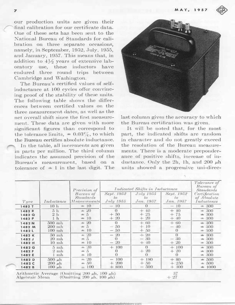
The Bureau' cer ified ....-alues of self
inductan c e at 100 cycles off r convin c
ing proof of th e tability of the e units.
Th following table ·ho-\YS the differ
ences be tween certified values on th e
th.re n1ea uremen date · , a wel l a the
net overall hif t ·in e the fir 1nea� ure
rn.en t. These data are ()'iv n with n1ore
ignificant figures than corre ·pond to
the tole r anc e limit , :±:: 0.03 , to ·which
the Bureau certifies absolute inductan e.
In the table, all increment ar give n
in part per million. The third column
indicates the a urn d p re ·ision of the
Bureaus mea uren1ent, ba ed on a
tolerance of :±:: 1 in th e last digit. The
MAY. 1957
last column giv the accuracy to which
the Bureau ce rt ificat ion. was given.
It will b n t d that for the most
part the indicated shifts are random
in h ara ter and do no greatly exceed the re olution of the Bureau inca ·urements. There is a 111oderate preponderance of po ·itive ·h ift , in r a e of indu tanc . Only the 2h, lh and 200 µh
uni ·bowed a progres iv uni-direc-
Tolerance of
Precision of Indicated Shifts in Tndnctance B urean of Standards
Bnrean of Sept. 1952 f(uularrls to
Tyr>e Ind1tclance .11 eas11re111enls Jitly 1955 1482 T 10 h == 10 - 10
1482 R 5 h == �o 0
1482 Q 2 h =5 + 50
1482 p lh == 10 + 20
1482 N 500 mh == 20 0
1482 M 200 mh =5 - 50
1482 L 100 mh == 10 - 50
1482 K 50 mh == 20 - 20
1482 J 20 mh =5 0
1482 H 10 mh == JO - 20
1482 G 5 mh == �o + 100
1482 F 2mh =5 0
1482 E 1 mh == 10 0
1482 D 500 µh == 20 - 100
1482. c 200 µh == .50 + 200
1482 8 100 µh == 100 + 800
Arithmetic Average (Om.itting :WO µh, 100 µh) Alg bra.ic �lean (Omittin� :200 µh, 100 µh)
Jut11 1905 to
Jan. 1957 0
+..J.O + 25 + 20
+ 60 + 10
+ 50
+ 20 - 30 +-:1-0
0 + 20
0
+ l 0 + 50 - 500
Seµt. 1952 to
Jan. J,9!j7 - 10
+ 40 + 75 + 40
+ 60 - ..J.O
0
0 - 30 + 20
+ 100 + 20
0
+ 80 + 250 + '.300
;37 + 27
Certification of Absolnte Inductance
== :300 --== 300 = 300 == 300
== 300 == 300 ==:-mo
= 300 == :300 == 300
= 300 = ;300 = 300
== 500 == 500 == 1000
www.americanradiohistory.com

GENERA 1RADIO EXPERIMENTER 8
ti nal ·hift. , n 11 , t i1
µh) th • rall
h
tenperatur .· for
C'C'a.·i iv t b wi hin on
'1 he t n p 'ratur c > ffi<'i nt
n ·e, t ou + . 0 I 6, is
�'d r a. th pre is1on
ata,.
f th
r 11il-1 a�· r
w· au
Th "n all
hiH, mitlit er th h\· ]',.. l8 )I' l
a couYineinc:r i·roof hio-h d•<rr'' 0 f ta hili >' x il it d l y hi.· .· ·t of i11-
du ·t r.·.
m. ( '( ' r Jan · r quir l e11 :3.
'uch . · al i • and :.i.
n n-
.·i n. · wh n
ha\·e r turue<l
re ·alibration ·WU p ri >di '
t. ri .· an<l for th C'alibruti 1
f induC'tor.
ur wn 1 ra
11
A I \ T. .\:\'.£
AN ENGINEER'S COMPANY
If . r u know an
01· r ent
· d i1 ith<•r
n 111
m nt
n
. . nn<Y 1n
t : mau··
::\IR. JOH r 1 A at our mbridg
or
H ... l'U-ncl him
General Radio Company
www.americanradiohistory.com


