Page 1
John Tarpley, Editor
Fall—Winter 2015-2016 Volume 6 Number 2
In Memorial Gorst duPlessis David Lindow
With the passing of Gorst duPlessis this past April the
ornamental turning world lost much more than a friend,
and to many of us he was a very good friend. To those
whom Gorst mentored it is his friendship that we miss
most; along with the warm memories of the generosity,
warmth, and passion that he truly infused into all that
encountered him never to be forgotten and to be
perpetually missed. To be sure, it was often to Gorst that
my phone dialed on the dark days as I always knew I
would find encouragement. His passion was infectious, and
his generosity was more colossal than his frame. While
some may say that he didn't suffer fools well, his patience
to those devoted to learning showed magnanimity well
beyond the norm. He loved life which means that he loved
to learn and that he loved to pass on his knowledge to
those who sincerely desired to know. He had a curiosity and zest for life that made anyone around him
want to know more and want to understand. To those that desired it he shared any parcel of knowledge
he had---and he had a lot to share.
Gorst was a force. He claimed to have made over 10,000
boxes during his career, and who would argue? When the
math is done the sheer volume that left his shop on a
weekly basis was hard to believe for anyone who did not
know him. However, for anyone who knew him even
casually, the utterance of such a number seems modest. He
learned to turn using a pole lathe at age 12 from a former
German POW in South Africa. Afterward he did not turn
for many years, yet the passion was sparked. A passion not
just for wood turning alone but for craft in general; through
the years there would scarcely be a media that he did not
explore from carving and cabinetmaking, to blacksmithing,
and goldsmith work. This passion personified him until the
end too. The week before his demise we set up his straight
line machine so that he could produce a new series of pens in a style he'd never explored. Even though it
was a force for his lifetime these explorations would have filled the lives for four ordinary men. Such is
the case with men of passion, curiosity, vitality, and love; and in the process they inspire scores of others
Gorst at his Armbruster lathe making a triple finial.
Gorst discussing his work at the 2013 AAW
Instant Gallery in Tampa, Florida.
Page 2
Page 2 Fall—Winter 2015-2016
toward the same goal. Even if we never reach the pinnacles he did, those of us whose lives were touched
can easily say that he moved us forward faster than we'd have otherwise been able to go. Our work not only
improved and increased, but our lives were enhanced overall. Gorst was indeed a force of the type that only
comes around every so many generations. We were fortunate enough to behold it and each of us that
aspires to his level will keep that force alive.
Words cannot express how grateful I am that he invited me into his life, and they cannot express how much
I miss him. I treasure every object he gave me, but what I treasure the most are the memories he created
and the gifts he imparted to my craftsmanship that I pledge to carry to the generation after me to keep this
force alive.
Gorst—A Rememberance John Tarpley
I think anyone in woodturning circles knows the name Gorst
duPlessis and his work. Many of you can say that you were friends
with Gorst, unfortunately I didn’t get to know him that well.
However, I can say that I knew and respected him. I had known
Gorst’s name almost from the time I began turning. I can’t
remember which AAW meeting, but I was in the Instant Gallery
talking with Bonnie Klein when Gorst walked up to speak with
her. She graciously introduced him to me and included me in the
conversation. After a few minutes Gorst gave a mischievous smile
and pulled a silver disk from his pocket to show us. That was my
first encounter with guilloché . Gorst had just completed the piece
before coming to the
meeting. Having no idea how the piece had been done, since I
hadn’t started on my OT journey at the time I’m sure I just
gawked at it and didn’t add anything useful to the discussion. I
had the opportunity to meet Gorst
at several meetings in following
years and he was always
welcoming and interested in
sharing his latest insights. In 2012
OTI produced three DVDs of
Gorst at work as a part of the
Symposium in Scranton, PA. I’ve
heard several versions of how
Gorst developed his signature
triple finial so I thought I’d review
the DVDs and see what he said there. When asked that question on the DVD
he said it was by “serendipity.” He was teaching a child to turn when he got
a phone call. He told the child to just slowly advance the cutter. By the time
he returned to the shop the cutter had gone past center and the triple was born. I don’t really know what
marks greatness or genius, but I know when I have been in its presence. I knew that whenever I spoke with
Gorst.
Gorst’s Finial Boxes 2013 AAW Instant
Gallery
Boxes 2013 AAW Instant Gallery
Gorst’s turned Pods 2013 AAW
Instant Gallery
Page 3
Page 3 Fall—Winter 2015-2016
A Letter From David
The year 2015 was one of travel. Ornamental turning took me from coast to coast and from the top to bottom
of the United States. Just from late August I saw New Orleans twice, Chicago three times, Seattle twice, and
Boston and Florida once each. While the traveling is tiring, I had the pleasure of seeing many of you; and the
number of seminars available to ornamental turners is unprecedented. Amongst the greatest of these pleasures
was being finally able to realize the hope of having a practical, hands on, guilloché class where beginners
could learn the pleasure of scratch work in metal. Five classes were held in Seattle, WA at the Memoria
Technica, www.mechanicalcurios.com, and all were well attended. You can see photos on their website.
Having 10 rotations at the AAW Symposium dedicated to ornamental turning was also a pleasure. We saw
many of you there. The program was diverse and reached both the experienced ornamental turners and those
just starting out.
The metal lathe and mill workshop held at my shop was also the realization of a desire I've had for a long time.
Seeing several of you progress from not being able to properly sharpen a cutter to being able to turn a piece to
a precise size with a nice finish was more than a simple pleasure for me.
2016, has opportunities as well including the AAW Symposium and the OTI Symposium. The AAW
Symposium in Atlanta will include the typical four rotations on ornamental turning and feature Jon Magill who
will handle both the rotations and the Special Interest Night. Jon will present two rotations on the various
chucks used in ornamental turning and two rotations on the various forms of the Universal Cutting Frame. The
Special Interest Night will feature the Spherical Slide Rest. With Jon's background and experience these all
promise to be educational and full of practical knowledge. The OTI Symposium will be in late September and
will feature Jean Claude Charpignon and David Wood-Heath as well as many others. The program is being
organized by Brad Davis. It promises to be enjoyable and worthwhile. I hope to see you all there. Additional
information on the program is in the Upcoming Meetings listing later in this newsletter.
Having been on the road so much new tool development has been slower than normal. However, the inventory
of items that have been out of stock for some time is coming back. If you've been waiting for an item for a
while, please check in for scheduling on completion dates. We have a lot of items in the works, and with the
inventory restocked we'll start working on some of those new items we've been waiting on for some time.
This issue of The Lindow Rose Engine News is once again not only a reflection of John's devotion and editing
skill but also an overall picture of the Lindow Rose Engine owners. There is a large and diverse group of
information. Brian's adaption and melding of Bill Ooms's and my instructions for making layered boxes should
be seen as a godsend. He's taken a relatively complex task, boiled it down to its simplest form, and
accomplished it on a Jet lathe. Reviews of meetings are always good as they bring back memories of details
we've long forgotten and spur us on to doing more OT. Another nice thing is to see someone retire and devote
more time to ornamental turning. This issue features an article by Steve White on an old idea he has adapted
and made new again. I thank each and every one of you who contributed to making this issue happen, and I
especially thank John Tarpley who has been more than patient with me for not getting my part done for quite
some time. The time he puts into these newsletters is astonishing, and it shows.
Page 4
Page 4 Fall—Winter 2015-2016
Editor’s Chips —John Tarpley
As I write this I just returned yesterday from the AAW Pittsburgh meeting. I mainly attended the
demonstrations in the OTI room. As you will see in the meeting review article in this issue we had some great
demonstrations this year. These meetings provide a different opportunity than the normal OTI meetings held
every other year. Attendees at these meetings also include those who are not currently ornamental turners, but
have an interest in learning if OT is for them. Additionally, this year Charles Waggoner’s demo on wood
stabilization attracted attendees who have no exposure to OT work. This gives us a unique opportunity to
interact with turners that are not familiar with our aspect of the art. I made it a point to speak with people that I
did not recognize who attended the demos, and I hope other OTI members did so also.
My first experience with attending an OTI demo room was way back at the 1995 AAW meeting in Davis, CA.
When I walked into the room I did not get a warm and fuzzy feeling. Rather I got looks that said, “We don’t
know you and what are you doing here?” Not knowing anything about OT I was quickly and hopelessly
confused just by the terminology being used by the speakers. I know that time at these sessions does not permit
complete and basic explanations for every step, but I was glad that this year’s meeting started with an
introductory talk which both outlined what would be covered in the following sessions and also provided some
basic information about OT. I think that in all these meetings there should be at least one very basic,
introductory session aimed at helping those attendees who are not yet ornamental turners decide if it is
something they want to explore further. This is an excellent way for us to attract new turners and grow the
numbers of our membership.
I also had the opportunity to encounter and perhaps counter the opinion of at least one attendee that OT work
was not for him because the machine does all the work and makes all the decisions, and he wants to maintain
his freedom and creativity as a turner. Unfortunately this attitude still exists among some people. I tried to
explain to him that OT would actually expand and increase his creativity and ability to create. I showed him
several pieces that he said he liked and then asked if he could create anything like them with his current skills
and equipment. I tried to explain that while the turning is done on OT equipment, that does not mean that the
lathe controls the work; but just the opposite, the turner controls the lathe and the creation comes from the
turner’s mind. Only time will tell if I was successful in helping to change his opinion.
[Ed. Note: Robert sent David the following note via email. If you have a paper chuck you may find this a
better option for the pen than the standard refills we have been using.]
David -
I wanted to let you know about a better pen refill for your Pen Holder.
When I first received your Pen Holder I had trouble with the filler which came with the Pen Holder. I needed
to apply a lot of pressure to get the pen started and even then it still would skip and gouge the paper.
I recalled that NASA had commissioned a special pen to use in space travel. It is called the Fisher Space Pen.
The pen is designed to write in all orientations with the use of a pressurized ink cartage. The pen and a refill
cartridge (model SPR4) is still available. The refill comes with an adapter which makes it compatible with the
Parker style refill used in the Pen Holder.
There are several sources that carry the Space Pen refill. I have found it on the Amazon and Staples websites. I
purchased a space Pen refill from my local Staples store.
I have much better results using the Fisher Space Pen refill.
Robert Key
Letter to the Editor
Page 5
Page 5 Fall—Winter 2015-2016
Turner Profile—Brad Davis This issue we profile Brad Davis. Brad is the Vice-President of OTI and an avid
ornamental turner. He has presented at meetings and recently took a trip to
England and Europe where he was able to visit some ornamental turners, their
shops, and also museums. We hope he will be able to share his trip in a future
issue. Brad presented at the 2015 AAW meeting and there is a review of his
presentation later in this issue.
Brad’s website is www.rescuedwoodcreations.com. He chose the name as a
tribute to his father, Arthur. Brad says, “My dad loved the game of golf. He would
play nine holes and then hunt golf balls for nine holes. I once asked him why he
did this and he replied that it was his duty to ‘rescue’ these lost golf balls.”
Brad continues, “Over the years he was able to accumulate many buckets of balls.
To put it another way, I don’t lack for ‘shag’ balls. So it must be in my DNA. I have spent countless hours at
tree dumps, saw mills, and in the woods accumulating enough material to last my life time. My goal is to
create a finished product that is pleasing to the eye, hence, you guessed it…Rescued Wood Creations.” Brad’s
website contains methods of processing rescued wood to obtain highly figured wood.
Brad graduated from Iowa State in 1981 with a degree in Agronomy. For his first 15 years after college he was
employed as a Golf Course Superintendent in Texas and Oklahoma. For the last 19 years he has been an owner
operator of a Midwest pizza/chicken/buffet franchise.
He says about his woodworking, “I have been a woodworker of sorts all my life picking up turning in earnest
around 2004. My wife of 30 years has been very supportive of my hobby as she rarely questions anything
concerning my hobby and for this I am blessed. Following Gorst duPlessis’ recommendation, I try to spend at
least 30 minutes a day in my shop. This allows me to be somewhat productive as well as honing my skills.”
“I have what I consider my dream shop. Its attached to the garage so I eliminated the "dust migration" to the
living room syndrome. I have an old South Bend 9" lathe to shape stock. I have 2 traditional lathes for turning,
one a Oneway 1224 for smaller projects and a Stubby 750 for larger projects. In 2010 I purchased a Lindow
Rose Engine and last year I bought Holtzapffel 1942 from Gorst duPlessis. The South Bend is used primarily
for my ornamental work as it is critical to begin a project with wood with uniform dimensions.”
“I love to do both traditional and ornamental turning so I have not specialized in either. Many projects
incorporate both types of turning. I decorate most appropriate surfaces. An example of this might be a small
hollow form with a rose engine decorated lid and finial. My newest love is Alice, the Holtzapffel I bought
from Gorst. I am still in the learning process, however, the things this machine is capable of are unlimited. My
first projects involved reciprocation. In reciprocation, the cutter is fixed on a moving cross slide and the wood
is manipulated.”
“I am in the process of learning how to use the undulater. A way to describe undulating is reciprocation on
steroids. You use the same basic procedure for reciprocation and then add another linear pattern to the process.
The end product is incredibly unique.”
My goal is to create a finished
product that is pleasing to the eye.
Page 6
Page 6 Fall—Winter 2015-2016
Geometric chucks are a fascinating and interesting accessory for
ornamental turning. The antique ones are also expensive and difficult to
find. Building one requires a lot of machinist skills. I have been looking
for a way to cut many of the patterns they create by building a simpler and
inexpensive alternative. I found an idea in a cd I received from Frank
Dorian which contains a story from the English Mechanic from 1882-83
about adding gears to a rose engine. The story was hard to understand, but
I was able to adapt it and this is my version. My Spirograph idea does
about 90% of what the gearing does, but by adding a second spindle with
gears one can multiply any rosette. The photo above is a 3 hour mock-up I did on a late Sunday night from
scrap material, just to see if the idea might work. The mock up worked well so I decided to develop it further.
These three photos show my current design. The
second spindle is a 1" hollow tube. I use a hollow tube
because a solid tube puts too much weight on that side
of the lathe so the rose engine does not work properly.
The second spindle is held by two stringers with
bearings. The spring on the rose engine must be
loosened to allow maximum rocking. As you can see
in the overhear and backside photos, I added a 5
pound weight suspended from a string and pulley to
pull the headstock to the right. As shown, I have a 100
tooth gear on the main spindle, a 70 tooth idler gear in
the middle, and a 20 tooth gear on the second spindle
giving a 5:1 ratio. This ratio can easily be changed by
varying the gears. As suggested by the article I have
mounted the rosette on the second spindle, seen in the top two photos, off center. I have used 1/2" of offset.
The rubber is mounted on the side of the second spindle. I used a second rubber tower which I mounted by
drilling and tapping two holes in the table. I test the patterns using a paper chuck and pen. Then I can cut the
patterns I like.
Double Spindle Modification Steve White
Page 7
Page 7 Fall—Winter 2015-2016
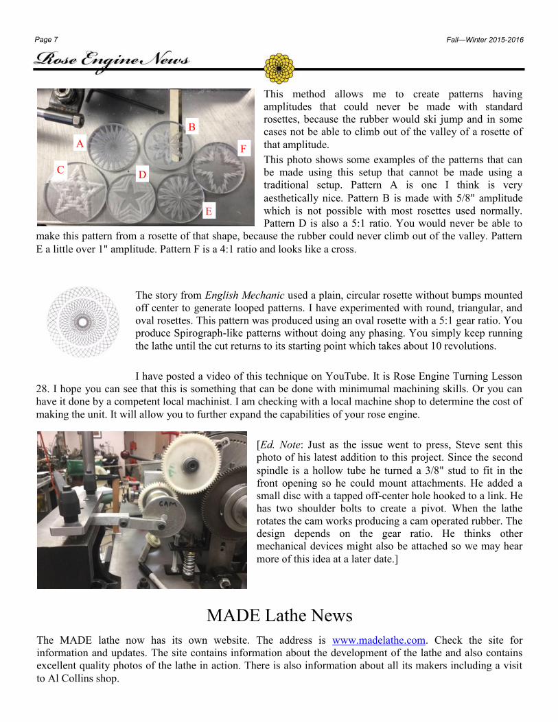
This method allows me to create patterns having
amplitudes that could never be made with standard
rosettes, because the rubber would ski jump and in some
cases not be able to climb out of the valley of a rosette of
that amplitude.
This photo shows some examples of the patterns that can
be made using this setup that cannot be made using a
traditional setup. Pattern A is one I think is very
aesthetically nice. Pattern B is made with 5/8" amplitude
which is not possible with most rosettes used normally.
Pattern D is also a 5:1 ratio. You would never be able to
make this pattern from a rosette of that shape, because the rubber could never climb out of the valley. Pattern
E a little over 1" amplitude. Pattern F is a 4:1 ratio and looks like a cross.
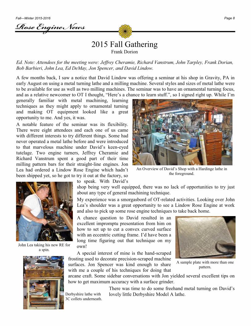
The story from English Mechanic used a plain, circular rosette without bumps mounted
off center to generate looped patterns. I have experimented with round, triangular, and
oval rosettes. This pattern was produced using an oval rosette with a 5:1 gear ratio. You
produce Spirograph-like patterns without doing any phasing. You simply keep running
the lathe until the cut returns to its starting point which takes about 10 revolutions.
I have posted a video of this technique on YouTube. It is Rose Engine Turning Lesson
28. I hope you can see that this is something that can be done with minimumal machining skills. Or you can
have it done by a competent local machinist. I am checking with a local machine shop to determine the cost of
making the unit. It will allow you to further expand the capabilities of your rose engine.
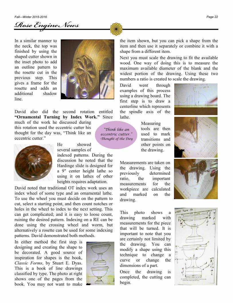
[Ed. Note: Just as the issue went to press, Steve sent this
photo of his latest addition to this project. Since the second
spindle is a hollow tube he turned a 3/8" stud to fit in the
front opening so he could mount attachments. He added a
small disc with a tapped off-center hole hooked to a link. He
has two shoulder bolts to create a pivot. When the lathe
rotates the cam works producing a cam operated rubber. The
design depends on the gear ratio. He thinks other
mechanical devices might also be attached so we may hear
more of this idea at a later date.]
A
B
C D
E
F
MADE Lathe News
The MADE lathe now has its own website. The address is www.madelathe.com. Check the site for
information and updates. The site contains information about the development of the lathe and also contains
excellent quality photos of the lathe in action. There is also information about all its makers including a visit
to Al Collins shop.
Page 8
Page 8 Fall—Winter 2015-2016
2015 Fall Gathering Frank Dorion
A few months back, I saw a notice that David Lindow was offering a seminar at his shop in Gravity, PA in
early August on using a metal turning lathe and a milling machine. Several styles and sizes of metal lathe were
to be available for use as well as two milling machines. The seminar was to have an ornamental turning focus,
and as a relative newcomer to OT I thought, “Here’s a chance to learn stuff.”, so I signed right up. While I’m
generally familiar with metal machining, learning
techniques as they might apply to ornamental turning
and making OT equipment looked like a great
opportunity to me. And yes, it was.
A notable feature of the seminar was its flexibility.
There were eight attendees and each one of us came
with different interests to try different things. Some had
never operated a metal lathe before and were introduced
to that marvelous machine under David’s keen-eyed
tutelage. Two engine turners, Jeffrey Cheramie and
Richard Vanstrum spent a good part of their time
milling pattern bars for their straight-line engines. Jon
Lea had ordered a Lindow Rose Engine which hadn’t
been shipped yet, so he got to try it out at the factory, so
to speak. With David’s
shop being very well equipped, there was no lack of opportunities to try just
about any type of general machining technique.
My experience was a smorgasbord of OT-related activities. Looking over John
Lea’s shoulder was a great opportunity to see a Lindow Rose Engine at work
and also to pick up some rose engine techniques to take back home.
A chance question to David resulted in an
excellent impromptu presentation from him on
how to set up to cut a convex curved surface
with an eccentric cutting frame. I’d have been a
long time figuring out that technique on my
own!
A special interest of mine is the hand-scraped
frosting used to decorate precision-scraped machine
surfaces. Jon Spencer was kind enough to share
with me a couple of his techniques for doing that
arcane craft. Some sidebar conversations with Jon yielded several excellent tips on
how to get maximum accuracy with a surface grinder.
There was time to do some freehand metal turning on David’s
lovely little Derbyshire Model A lathe.
An Overview of David’s Shop with a Hardinge lathe in
the foreground.
John Lea taking his new RE for
a spin.
A sample plate with more than one
pattern.
Derbyshire lathe with
3C collets underneath.
Ed. Note: Attendees for the meeting were: Jeffrey Cheramie, Richard Vanstrum, John Tarpley, Frank Dorian,
Bob Barbieri, John Lea, Ed DeMay, Jon Spencer, and David Lindow.
Page 9
Page 9 Fall—Winter 2015-2016
But it wasn’t all work! Becky Lindow, our gracious hostess,
kept us well nourished over the course of our stay, and the
conversation around the Lindow table was always interesting
and great fun too. Another contribution Becky made to our
enjoyment was her beautiful flower garden which greeted our
eyes every time we emerged from the shop.
Gravity, Pennsylvania is a quiet corner of the world. However,
if your interest happened to be ornamental turning, David’s
workshop was a Mecca of learning opportunities offered in a
context of friendly and like-minded fellow OT enthusiasts
gathered in a very well equipped workshop. I feel comfortable
speaking for the other attendees as well as myself to thank David and Becky for their warm hospitality and for
a memorable learning experience.
Everyone wants to know how this is done.
Jon’s single lipped grinder for making cutters.
[Ed. Note: See the AAW meeting review for more on
Jon’s cutters.]
Jon Spencer gave a lot of his time to
teach during the weekend.
The master looks up from his
work.
Making pattern bars for a
straight-line engine.
Page 10
Page 10 Fall—Winter 2015-2016
Ed. Note: In our last issue as part of our review of the 2014 AAW meeting there was information on making a layered box. To
expand on that information the following article is included in this issue. Two different methods are used in the article, one
incorporating a leveling chuck and one using an MT 2 taper which often eliminates the necessity of using a leveling chuck.
Introduction:
This ornamental turning project is covered in two
separate parts. The first part explains how to layer
several types of wood and, the second part details
how to decorate the outside of the layered wood
piece. Additional information can be found in the
two articles by Bill Ooms titled Mini Metal Lathe for
Wood, in American Woodturner vol. 28, no. 1, p.
29–35, 2013 and Ornamental Turning-Patterns Cut
Through Thin Layers, in American Woodturner
vol. 28, no. 2, p. 42–46, April 2013. Both articles
contain a lot of information that relates to this
project. The layered box on this page was completed
by David Lindow. The two other layered boxes at
the end of the article were completed by Brian Clarry
using these instructions.
Equipment Used
In Part 1 the the layered box is prepared using a Jet
mini-lathe with a Hardinge slide rest. The slide rest
is attached to the mini-lathe with the Lindow
Hardinge Mount.
In Part 2 the layered box is ornamented using the
Lindow Rose Engine with a
Double Eccentric Chuck.
Wood—Good woods for
layering are African Blackwood,
Tamboti, Mopane, Pink Ivory, Holly, Boxwood,
Bloodwood. Holly or Maple veneers can also be
used. Bill Ooms covers the technique for using
veneers in his April 2013 article previously
mentioned.
Mounting—Mounting a 4 jaw chuck on a Morse
Taper Adaptor to utilize the Morse Taper (MT) on
both lathes is exponentially more accurate than using
threaded adaptors (some lower-end lathes will
require that the MT bore be returned and trued). A
piece mounted in a chuck on a MT runs accurately
and true if the taper bore is clean and free of debris.
To maintain the repeatability do not remove the
piece from the chuck during the machining steps.
Using a MT will eliminate the need for a leveling
chuck. For this example a Talon chuck with a #2
Morse taper that will fit both the mini-lathe and the
Lindow Rose Engine is used.
[Ed. Note: If you do not have a MT on your RE then
using a Leveling Chuck, will require much more
adjustment and time to obtain the required
accuracy.]
Metal HSS Cutters—The straight cutter is a 3/8"
HSS blank. The end of the cutter is ground to less
than 90°, and the face of the cutter is 15° from
vertical. The left hand side of the face is ground 5° from vertical.
Aligning the Hardinge slide rest—On a regular
lathe round a piece of wood between centers with a
tenon at one end that fits a Lindow Expansion
Chuck. The Expansion Chuck will be used when
ornamenting the layered box in Part 2. Clamp the
blank in the 4 jaw chuck. Install a regular metal
cutter in the Hardinge tool holder and use a square to
ensure the tool post is perpendicular to the cross
Ornamentally Turned Layered Box Brian Clarry & David Lindow
Page 11
Page 11 Fall—Winter 2015-2016
slide. Turn the length of the blank, and check the
diameter at each end of the cylinder. If the diameters
are not equal loosen the two swivel lock cams on the
Hardinge top slide, and use the protractor to adjust
the angle accordingly. Repeat the process until the
diameter of the cylinder is equal at each end.
The mini-Jet can be set to high speed, except when
drilling holes with Forstner bits.
Part 1—The Layered Box
Introduction:
The layered box for this project consists of three
layers. The outside layer is blackwood, the middle
layer is holly, and the inside layer is pink ivory. The
final height of the layered box is 1 1/2".
Note: The blackwood layer in this project has a
3/16” thick bottom.
When cutting and ornamenting through thin layers,
the depth of cut must be controlled accurately to get
the desired pattern. When cutting on the side of a
cylinder the amplitude of the rosette must match the
cut depth for optimum results. For this box the outer
layer (Blackwood) is 0.120”, middle layer (Holly)
0.060”, and the inner layer (Pink Ivory) is 0.060”.
Therefore, the amplitude of the rosette selected must
be less than 0.240".
Layering Process:
Step 1—Between centers on a regular lathe round
each of the three woods and create a 1/4" tenon at
one end. Based on the type of jaws of the holding
chuck cut either straight or dovetail tenons.
Note: If the tenon will be used to hold the
Blackwood when decorating, ensure the diameter
of the tenon (in clamping mode) fits the Lindow
Expansion Chuck. See Step 3 in the “Where to
ornament on the layered box” section of this
article.
Hint: Set the
straight cutter to
center height, and
use the corner of the
straight metal cutter
to cut the wood. The
cutter should be
clamped at an angle
in the tool holder to
stop the tool post touching the wood.
Rough Turned Final Diameter
Blackwood: 2.25" x 2.75" 2.500"
Holly: 2" x 2.375" 2.260"
Pink Ivory: 2" x 2.25" 2.140"
Step 2—Clamp the Pink Ivory in the holding chuck.
Use the straight metal cutter in the Hardinge tool
holder to first, squarely face the end of the cylinder,
and second, to turn the diameter to 2.140".
Note: After the layered box has been ornamented the
Pink Ivory will be bored to leave a sidewall thickness
of 0.060".
Page 12
Page 12 Fall—Winter 2015-2016
Step 3—Replace the Pink Ivory with the Holly. Use
the straight metal cutter in the Hardinge tool post to
first, squarely face the end of the outside of the
cylinder, and second, to true the diameter.
Step 4—Bore a hole
1 3/8" deep. Begin
by using a 1 1/4"
Forstner bit and
then enlarging the
hole using a 1 1/2"
Forstner bit.
Hint: The depth stated is an estimate and will depend
on the height of the wood pieces. However, it is
important to remember where the bottom of the Pink
Ivory inside layer is to ensure you do not go through
the bottom when boring the inside layer.
Step 5—
Install a
boring bar in
the tool
holder and set
the boring bar
to center
height.
Hint: It is important to keep the boring bar tool
holder clean of wood dust.
Make multiple small cuts boring out the inside of the
Holly to a diameter of just under 2.140". Go as deep
as possible without going through the bottom.
Step 6—Use a 1/4" wood
drill to drill through the
bottom of the Holly. This hole allows air to escape
when inserting the Pink Ivory cylinder.
Step 7—Using the boring bar, slowly increase the
inside diameter of the Holly cylinder so that the Pink
Ivory cylinder will fit loosely, not tightly, into the
Holly.
Step 8—Use a small amount of PVA glue on the
lower part of the Pink Ivory cylinder and push it
quickly into the Holly. After the glue has dried use
the straight metal cutter to face the end of the outside
of the cylinder so that the two woods are level.
Note: Two methods have been suggested to glue the
inserts. The first is using PVA glue as described
above, and then using thin CA glue on the non-glued
area when cutting the pattern. The second method
uses 20-minute epoxy covering the entire insert.
Step 9—To complete the Holly cylinder true the
diameter of the Holly to be 2.260".
Step 10—Replace the Holly with the Blackwood.
Use the straight metal cutter in the tool holder to
first, face the end of the outside of the cylinder, and
second, true the diameter.
Page 13
Page 13 Fall—Winter 2015-2016
Step 11—Bore a hole 1 1/4" deep using a 1 1/4"
Forstner bit. Enlarge the hole using a 1 5/8" Forstner
bit to complete the boring.
Step 12—Use a boring bar to cut the inside of the
Blackwood to a diameter of just under 2.260" with the
bottom of the cylinder flat making multiple cuts.
Either, use a 1/16" wood drill to drill a hole through
the bottom of the Blackwood or alternatively size the
Holly cylinder for a loose fit so the air will escape
between the sides of the Holly and Blackwood. Only a
1/16" hole is used here since this hole will be visible
and must be plugged.
Step 13—Finally,
slowly increase
the diameter of
the Blackwood
cylinder so that
the Holly cylinder
will fit loosely,
not tightly, into
the Blackwood.
Step 14—Use a small
amount of PVA glue
on the base and lower
part of the Holly
cylinder and quickly
push it into the
Blackwood allowing
the air to escape.
Step 15—Use a straight
metal cutter in the tool
holder to face the end of
the outside of the cylinder
so that the three woods
are level.
Step 16—To complete the
Blackwood reduce the diam-
eter to 2.5" leaving a 3/16"
shoulder at the base.
Note: The complete length
of the cylinder can be
1.5”, as in this project.
The lower 3/16” will be
shaped using an ogee
curve.
Other designs for layered boxes
The first design is just a
straight cylinder with a
3/16” thick base that can be
ornamented both internally
and externally.
The second is the same
design, but the diameter of
the Blackwood was
sufficient to cut a shoulder
at the outside of the base.
An ogee can then be cut on
the shoulder for decoration.
The third design is a
cylinder with no base. It has a layered plug glued in
the base which is ornamented inside and outside to
show the layering.
Page 14
Page 14 Fall—Winter 2015-2016
Part 2—Ornamenting the layered box
This part describes decorating a small box with
ornamentation on the outside and base. The lid is
separate from the base and includes a finial. The rose
engine used in this project is a Lindow Rose Engine
and the choice of chuck is the Double Eccentric
Dome Chuck.
The rosette used for ornamentation is an 18 bump
pumping rosette on the rocking surface using a 2"
rubber. The rosette amplitude is 0.165".
This document also refers to the Lindow Rose Engine
Alignment Procedures available from Lindow
Machine Works.
Leveling the Double Eccentric Chuck:
To ensure accuracy cutting through the layers it is
first necessary to
1. set the UCF cutting head horizontally.
2. set the cutting frame to center height.
3. level the first slide of the Double Eccentric
Chuck.
4. level the second slide of the Double Eccentric
Chuck.
5. Set the Dome Chuck or Index Head at center
height to the spindle.
Step 1—Setting the UCF cutting head
horizontally
Install a square wood blank in the Index Chuck, and
set the red dial on the Index Chuck to 0. Position a
square against the side of the blank, and move the
blank until it is square to the slide rest.
Install the Universal Cutting Frame on the tool post
and position the cutting head at the bottom of the
blank. Move the red dial of the Index Chuck to 45°.
Make a small cut, then move the cutting head and
make another cut so the edges of the two cuts meet.
The two cuts should make a continuous line. If the
two cuts are not in the same plane, then the UCF
needs to be tapped slightly to correct the tilt. Make
two more cuts and check again.
Refer to Lindow Rose Engine Alignment Procedures
document Section 2-2.1a for more information on the
process.
Step 2—Setting the UCF to center height
Install a square wood blank in the Index Chuck.
Install a 45° rubber in the valley of a 24 bump sine
rosette. Move the UCF slightly to one side of the
centerline and make a small cut.
Move the rosette 12 times (180°) and make another
cut. Both cuts should be at the same height.
If not, adjust the UCF by loosening the tool post
lever and adjust the UCF up or down to correct the
difference. Make two more cuts to check the new
adjustment.
Refer to Lindow Rose Engine Alignment Procedures
document Section 2-2.2 for more information on the
process.
Step 3—Level the first slide
Refer to Lindow Rose Engine Alignment Procedures
document Section 3.3 - 3.3a for more detailed
information on the process.
On the Double Eccentric Dome Chuck there are two
slides both of which have to be level with the table
when the headstock is at top dead center.
Place an adjustable level (Starrett No 78 used here,
red arrow) on the bed of the sliderest and adjust the
bubble to the center. Place the level on top of the
headstock. Move
the knurled
adjustment nut, that
adjusts the
headstock, to move
the headstock to
top dead center and
center the bubble
of the level.
Install a 24 bump
sine rosette with a 45° rubber placed into a valley of
the rosette. Set the detent on the Crossing Wheel to
24.
Move the adjustable
level to the top of the
first slide. If the first
slide is not level use
the key to turn the
Crossing Wheel worm
until the first slide is
level with the
Page 15
Page 15 Fall—Winter 2015-2016
headstock.
Step 4—Level the second slide
With the first slide leveled rotate the headstock 90° or 6 bumps to level the second slide.
Place the adjustable level on the headstock and check
that the headstock is at top dead center, then place
the adjustable level on the side of the second slide. If
the second slide is not level there are two ways to
adjust the slide. Either loosen the four screws at each
corner of the aluminum plate, or loosen the four bolts
holding the second slide to the center of the
aluminum plate. After adjusting and leveling the
slide, retighten the screws.
Where to ornament on the layered box:
Step 1—Adjust headstock to rock equally either
side of top dead center
Install an 18 bump pumping rosette and use a 2"
rubber on the rocking surface.
Use a dial indicator against the top of the headstock
and an adjustable level on the headstock to check that
the travel each side of top dead center is the same.
Refer to Lindow Rose Engine Alignment Procedures
document Section 1 - 1.2 for more detailed
information on the process.
Step 2—Centering the cutting head vertically
Hint: Before ornamenting the layered box ornament
a test piece of the same dimensions.
First, using a dial indicator against the headstock set
the second slide to horizontal. Turn the cutting head
so that the cutter is cutting vertically. Move the
cutting frame so the cutting head is close to the
center of the spindle.
Start the cutting frame and move the cutting head to
make a small cut on the test piece.
Second, turn the Eccentric Chuck by 180° and make
a second cut.
Third, measure the size of the gap between the two
marks and move the cutting frame by half the
amount. The cutting frame should now be centered
vertically to the spindle.
Turn the cutting head back to horizontal.
Note: It will be necessary to check the cutting head is
horizontal as described above.
Step 3—Positioning the test piece
Note: This holding method uses a Lindow Expansion
Chuck clamped onto the tenon of the layered box.
Alternatively, a 1 1/4” hole may be bored in the
layered box and an Expansion Chuck used to expand
into the hole. This is a more secure method of
holding the layered box while decorating.
Mark on the side of the layered box for the location
of the center of the pattern. Use the red handle on the
second slide to move the layered box so that the mark
is in line with the center of the cutting head.
Move the cutting head to one side of center. In this
pattern the dial was moved 3/4 turn. (0.075")
Step 4—Ornamenting the test piece
Turn on the cutting frame.
Turn the Double Eccentric
Chuck and move the cutting
head in to just touch the
surface setting the dial to 0.
Make a shallow cut and
check the orientation of the
cut. Cut to a depth of 0.165".
Ornamenting the layered box
Truing the layered box:
Clamp the layered box in the Expansion Chuck, and
screw the Expansion Chuck on the Index Head.
Ensure the layered box is clamped securely to
prevent the box from separating from the chuck when
ornamenting.
The next step is to check the run-out of the layered
box both axially and radially.
Note: Bump and Shim Method. - If the layered work
piece is not axially true it is sometimes possible to
use your hand or a mallet to tap the box into true. In
some cases this is about the only method available. It
takes experience and skill, and it often requires a
degree of compromise. This method will be used later
when setting the box into a Dome Chuck.
Page 16
Page 16 Fall—Winter 2015-2016
Step 1—Check that the box is axially aligned
Use a dial indicator
at each end of the
layered box to
check for axial
alignment. Unlock
the Index head and
turn the layered
box checking the
amount of run-out
at each end of the
box. If the amount is the same at each end it is
axially true. If the amount is different gently tap the
box (bump method—see above) until it runs true.
Even though the layered box could be axially aligned
at each end, the box could still rotate off of its axis
This can be corrected when calculating the depth of
cut.
Step 2—Check that the box is radially aligned
Use a dial indicator
on the end of the
box. Unlock the
Index head and turn
the layered box and
check the amount of
run-out at the end of
the box. If it is out
of alignment use a
piece of shim stock between the box and the holding
chuck.
Calculating the depth of cut.
Step 1—Position a dial indicator where the pattern
will be cut and set the Index Head to 0°. Increment in
45° steps and mark each increment on the blue tape.
Set the Index Head to 0 and the dial indicator to 0.
Move the Index Head by 45° and note the difference
from the 0 reading on the dial indicator. Repeat for
each of the 8 positions, noting the differences for
each position.
In this project the differences are shown in the table.
The difference will be
added to the depth of
cut when ornamenting.
Hint: When centering the cutting head make
adjustments and check again before cutting deeper.
Move to a new position on the Index Head if
additional checks need to be made. This will prevent
damaging the piece while centering.
Step 2—Cutting the pattern
Calculate the approximate depth of cut using the
offset for each of the 8 patterns. Using the 18-bump
pumping rosette and the 2” rubber, the depth of cut is
0.165". For this project the offset was added to
0.165" to calculate the approximate depth of cut. The
depth of cut may change when cutting the first
pattern.
Note: If the offset was a negative value then the offset
amount should be subtracted from the 0.165".
Cutting the pattern
Step 1—Using the layered box, repeat the cutting
head centering and pattern positioning steps as
described above for the test piece.
Move the cutting head to one side of center. In this
project the cutting head was moved 0.075" or 150 on
the dial.
Step 2—Turn on the cutting frame and turn the
Double Eccentric Chuck. Move the cutting head in to
just touch the surface and set the dial to 0. Make a
shallow cut and check to ensure the ornamentation is
positioned correctly.
First pattern—For the first pattern move the cutting
head in ensuring all three layers are cut. Note the
depth of cut as this may be different from the
expected 0.165".
1. 0 5. 0.006"
2. 0.002" 6. 0.007"
3. 0.005" 7. 006"
4. 0.005" 8. 002"
Pattern Offset Depth of Cut
1 0 0.165"
2 0.002" 0.167"
3 0.005" 0.170"
4 0.005" 0.170"
5 0.006" 0.171"
6 0.007" 0.172"
7 0.006" 0.171"
8 0.002" 0.167"
Page 17
Page 17 Fall—Winter 2015-2016
In this project the three layers were not cut until the
depth of cut was 0.185". The depth of cut table was
adjusted accordingly.
Rest of patterns—To
cut the rest of the
patterns move the index
by 45°, and repeat the
operation. Remember to
adjust your depth of cut
in accordance to the
depth of cut calculation
described above.
Boring the inside layer
Step 1—The next step is to bore a hole in the inside
layer.
Use a mini-lathe to bore a hole beginning with a 1 ¼"
Forster bit and then enlarge the hole using a 1 ½"
Forstner bit. Remember the long point on the cutting
area of the Forstner bit.
Step 2—Install a boring bar in
the tool holder and set the boring
bar to center height. Remove the
inside leaving the thickness of
the side to be greater than 0.60",
and the base ¼". Make a pass across the bottom of
the box to remove the point mark of the Forstner bit.
Hint: Be careful not to make the base or the side too
thin. Cutting the side too thin can cut through to the
patterns.
Lid of the Box
A lid was made from
Blackwood and Pink Ivory
with a Blackwood finial. A
shoulder was cut into the lid.
The inside of the lid was
decorated.
Pattern Offset Depth of Cut
1 0 0.185"
2 0.002" 0.187"
3 0.005" 0.190"
4 0.005" 0.190"
5 0.006" 0.191"
6 0.007" 0.192"
7 0.006" 0.191"
8 0.002" 0.187"
Ornamenting a pattern on the base
a. Use an end mill in the Drilling Frame to first
remove the tenon and smooth the complete face
of the base.
b. To ensure the pattern is cut centrally and at the
same depth lock the headstock at top dead center,
and check the base axially and radially. Refer to
Alignment Procedures document Section 3–3.4.
Install the 60° drilling cutter in the Drilling
Frame and ensure it is on center with the spindle.
c. Install the D8-250 Rosette and a 45° rubber.
d. Position the rubber in the valley of the rosette
with the drilling cutter in the center of the base.
Set the bottom slide dial to 0.
e. Cut the pattern using the following three steps.
Page 18
Page 18 Fall—Winter 2015-2016
Step 1—Central pattern
Move the drilling cutter in
to start cutting the pattern.
When the top of the eight
shapes looks like
barleycorns and the top of
the shapes is just below the
surface, stop cutting. Set the
top slide dial to 0, and move
the drilling cutter away
from the base.
Step 2—The first five cuts
of the outside pattern
a. Cutting the first five
cuts of the pattern
without phasing:
i. Move the drilling
cutter away from
the center, or
towards the
operator by
0.050" (100 on the
dial).
ii. Cut the next pattern until top slide dial
reaches 0.
iii. Move the drilling cutter away from the base,
and repeat a. i. thru a. ii. above until five cuts
have been made.
Step 3—Finishing the outside pattern
Rest of the pattern
a. Move the drilling cutter
away from the center,
or towards the operator
by 0.050" (100 on the
dial).
b. Phase by 3°, i.e.1 ½
turns on the Crossing
Wheel worm, or 1 turn
of the Auxiliary Rosette Holder.
Note: If the phasing key is turned clockwise the
shape of the pattern is right-handed. If turned anti-
clockwise the pattern is left-handed.
c. Cut the next pattern 0.005" deeper.
Repeat a. i. thru a. iii. above until the pattern is just
under ½" from the edge when the rubber is in the
valley of the rosette.
Ornamenting with a Lotus pattern
The Lotus rosette used in this ornamentation was
purchased from Jon Magill and modified to clamp on
the 1" spindle of the Lindow Rose Engine. A 1" collar
was drilled and tapped for three screws. The rosette
was drilled with three holes and attached to the collar
using three screws. The 1” collar, attached to the
rosette, was clamped on the outboard end of the
spindle.
Setting up the work piece for ornamenting
Step 1—Setting the UCF to center height
Install a leveling chuck and a holding chuck on the
spindle. Clamp a square wood blank in the holding
chuck. Install a 45° rubber in the valley of a 24 sine
rosette. Install the UCF touching the face of the wood
blank. Move the UCF slightly to one side of the
centerline and make a small cut.
Move the rosette 12 times (180°) and make another
cut. Both cuts should be at the same height. If not,
adjust the UCF up or down by half the difference.
Make two more cuts to check the new adjustment.
Refer to Lindow Rose Engine Alignment Procedures
document Section 2—2.2 for more information on the
process.
Page 19
Page 19 Fall—Winter 2015-2016
Step 2—Setting the UCF cutting head
horizontally
Clamp a different square wood blank in a holding
chuck and move the UCF so it is touching the face of
the wood blank.
First, make a small cut, then move the cutting head
slightly sideways and make another cut so the edges
of the cuts meet. The two cuts should make a
continuous line. If the two cuts are not in the same
plane then the UCF needs to be tapped slightly to
correct the tilt. Make two more cuts and check again.
Refer to Alignment Procedures document Section
2—2.1b. for more detailed information on the
process.
Step 3—Set headstock to top dead center (TDC)
Refer to Alignment Procedures document Section—
1 1.1.
Step 4—Check the work piece radially
Use a dial indicator against the side of the work piece
and adjust the leveling chuck so that the work piece
is adjusted radially with minimal eccentric
movement
Refer to Alignment Procedures document Section
3—3.4a. for more detailed information on the
process.
Step 5—Adjust headstock to rock equally either
side of top dead center
Install the 8-lotus rosette with a 45° rubber.
Use a dial indicator against the top of the headstock
and an adjustable level on the headstock to check that
the travel on each side of top dead center is the same.
Refer to Lindow Rose Engine Alignment Procedures
document Section 1—1.2 for more detailed
information on the process.
Step 6—Cutting the pattern
Mark on the side of the
layered box where the
center of the pattern will be
ornamented. Move the
layered box so that the mark
is inline with the center of
the cutting head.
Turn on the cutting frame.
Turn the layered box and
move the cutting head in to just touch the surface.
Make a shallow cut and check to ensure the
ornamentation is in the desired location.
Move the cutting head in until a pattern is cut. When
the second layer appears check that the layer appears
in all the cuts. If not, adjust the leveling chuck to
ensure that the layer does appear in all the cuts.
Move the cutting head in until all three layers have
been exposed and the correct depth is cut.
Step 6—Completing the box
Starting at the section ‘Boring the inside layer’ on
Page 10, complete the rest of the box.
Completed Box
Page 20
Page 20 Fall—Winter 2015-2016
OTI Sessions at 2015 AAW John Tarpley
This year’s
AAW meeting
was held in
Pittsburgh,
Pennsylvania.
OTI was again
given a room for
the entire
meeting and the
room was used
for 10 of the 11
rotations.
You can see from
this review that
the 2015 AAW
meeting was a
very useful one
for ornamental
turners. OTI did
an excellent job
organizing theses
sessions. It was
very nice that AAW allowed us to have a dedicated
room so equipment did not have to be transported
from room to room. This also allowed for informal
discussions by attendees between sessions.
I think all of us were acutely aware that there was a
missing presence at this year’s symposium with the
passing of
Gorst earlier in
the year. AAW
has a program
for groups or
individuals to
sponsor a demonstration room. Gorst had arranged to
sponsor the OTI room so we knew that his spirit was
there with us.
I also would be remiss if I didn’t acknowledge the
very important contribution provided by Jeffrey
Schnell. For several years Jeff has served as OTI’s
video guru. Each year he brings cameras, tripods,
cabling and all the other bits and pieces needed to
record the OTI sessions at the AAW meetings. I tried
several times to
get a good
photo of Jeff
for the
newsletter and
this was the best I got. The truth is that during the
meeting Jeff is in perpetual motion and never stops
long enough for a well composed and focused photo.
Here you see Jeff with two of the four camera setups
he brought for this meeting. Several times during the
meeting I saw him offering help and loaning
equipment to video techs working in other rooms so
his assistance made demonstrations in other rooms
better also. Jeff has posted a couple of YouTube
videos of images he made in the Instant Gallery and
the Empty Bowls and the Beads of Courage Box
areas. You can view these videos at https://youtu.be/
wpIPbAY4XO8 and https://youtu.be/
PkaqeWCZhDY.
The first rotation was
“Introduction to Ornamental
Turning & Rose Engines” by
David Lindow. David said that
while OTI certainly wanted to
impart training and new
information during rotations, it was also important to
provide some history and an introduction for anyone
attending who was new to OT. This rotation set the
tone for the remaining rotations and outlined what
would be presented in the rest of the meeting.
David began by
showing several types of machines and discussing
various lathes developed for ornamental turning.
The convention center is located on the
river. This is the deck off the meeting
area which allowed for fresh air
between sessions.
Behind the bridge you can see the
Pirate’s baseball park.
Page 21
Page 21 Fall—Winter 2015-2016
He then showed several pieces of
ornamental work using them to
illustrate the
type of shapes
and
decorations
that are
possible.
He also included examples
of engine turning. While
showing these examples
David emphasized that many
times the
beauty
and
seeming
complexity of OT work comes
from the interaction of shadow
lines and the contrasting patterns
formed by these lines.
To illustrate how OT work is
done David made a bottle
stopper to show several
techniques. He began by
using the flying saucer cutter
to cove the neck and add a
swirl pattern.
To add a bit of elegance to
the neck he used a shaped
cutter to add a small detail at
both the bottom and top of
the swirl adds an additional
shadow line to the piece.
He then used an
eccentric cutting
frame mounted in a
drilling chuck to
shape the head and
create a pattern on the
side of the stopper
head.
While he was doing this
he commented that he
likes to run the drilling
frame as fast as possible
during these operations
so he speeded up the
cutter by moving the
belt off the pulley and
running it on the drilling
frame shaft. This gives a
speed of about 10, 000
rpm.
The surface of the top
of the stopper was
decorated using the
flying saucer cutting
frame.
Page 22
Page 22 Fall—Winter 2015-2016
In a similar manner to
the neck, the top was
finished by using the
shaped cutter shown in
the inset photo to add
an outline pattern to
the rosette cut in the
previous step. This
gives a frame for the
rosette and adds an
additional shadow
line.
David also did the second rotation entitled
“Ornamental Turning by Index Work.” Since
much of the work he discussed during
this rotation used the eccentric cutter his
thought for the day was, “Think like an
eccentric cutter.”
He showed
several samples of
indexed patterns. During the
discussion he noted that the
Hardinge slide is designed for
a 9" center height lathe so
using it on lathes of other
heights requires adaptation.
David noted that traditional OT index work uses an
index wheel of some type and an ornamental lathe.
To use the wheel you must decide on the pattern to
cut, select a starting point, and then count notches or
holes in the wheel to index to the next setting. This
can get complicated; and it is easy to loose count,
ruining the desired pattern. Indexing on a RE can be
done using the crossing wheel and worm, but
alternatively a rosette can be used for some indexing
patterns. David demonstrated both methods.
In either method the first step is
designing and creating the shape to
be decorated. A good source of
inspiration for shapes is the book,
Classic Forms, by Stuart E. Dyas.
This is a book of line drawings
classified by type. The photo at right
shows one of the pages from the
book. You may not want to make
the item shown, but you can pick a shape from the
item and then use it separately or combine it with a
shape from a different item.
Next you must scale the drawing to fit the available
wood. One way of doing this is to measure the
maximum available diameter of the blank and the
widest portion of the drawing. Using these two
numbers a ratio is created to scale the drawing.
David went through
examples of this process
using a drawing board. The
first step is to draw a
centerline which represents
the spindle axis of the
lathe.
Measuring
tools are then
used to mark
transitions and
other points on
the drawing.
Measurements are taken on
the drawing. Using the
previously determined
ratio, the important
measurements for the
workpiece are calculated
and marked on the
drawing.
This photo shows a
drawing marked with
measurements for the piece
that will be turned. It is
important to note that you
are certainly not limited by
the drawing. You can
modify a shape using this
technique to change a
curve or change the
dimensions of a part.
Once the drawing is
completed, the cutting can
begin.
“Think like an eccentric cutter.” -Thought of the Day
Page 23
Page 23 Fall—Winter 2015-2016
To illustrate indexing using an
index plate David used a Jet
mini-lathe and the Hardinge
adaptor. After truing the work
he showed how he marks the
notches on an index plate
attached to the lathe shaft. An
indexing stop engages the
notches.
The main message of this
portion of the demo was that
while this is the traditional
technique for index work, it is
tedious, and requires good
concentration to prevent
errors in counting.
When using the Hardinge slide with the adaptor plate
on a mini lathe it is sometimes helpful to get more
movement away from the spindle with the bottom
slide. This can be accomplished by backing off the
safety screw from the slide. This will give about
another inch of movement.
Whenever you plan on indexing using a regular
lathe with a indexing plate and a powered cutting
frame it is important to unplug the lathe. This
prevents the possibility of accidentally turning on the
lathe while the cutter is also operating. This is an
easier accident than you might think since we are
accustomed to turning on the lathe to begin a cut. As
David said, this would certainly be a hair raising
experience.
Moving to the RE David
demonstrated that index
work is possible using a
rosette, crossing wheel, or
worm. In most cases
combinations of these
tools are used. David used
an eccentric cutting head
to both create the basic curve on the piece as well as
for decoration. This is where we returned to the
thought for the day, “Think like an Eccentric Cutting
Head.” By this he meant that the cutting head is
capable of certain cuts and not others. Therefore, to
use it properly and get the shape you want to make
you must recognize how to allow it to cut for you.
The first step is setting the needed eccentric cutting
head offset for the cutter being used. Using electronic
calipers makes this measurement very easy. The head
has two studs on the surface used to give accurate
points for measurements with calipers. First, measure
the width (diameter) of one stud. Second, measure
the width of the cutter being used. Add these two
numbers and set the caliper to the result. This
accounts for these two fixed measurements that have
to be included in your final offset. Now, without
moving the caliper, zero the caliper. Next the caliper
is set to the desired eccentric cutter offset and locked.
Using the caliper the cutter offset can be set
accurately by moving the slide on the cutter head
until the two pins contact the caliper arms. The cutter
head must be balanced since it is rotating
eccentrically. This is done by moving the supplied
counterweight blocks.
After cutting the desired
shape David used a 12 bump
rosette for the pattern. The
pattern required phasing so
David used a portion of the
crossing wheel that gave
him the needed phase
flexibility. In this case that
was the 96 division section. Since 96/12=8, settings 1
and 9 will be the same phasing and a setting of 4 will
equal phasing by 180°.
The eccentric cutting head
was set as described above
and then mounted in the
cross slide which was
adjusted to the previously
calculated angle measured
from the drawing. The first
round of circles was cut
around the bowl of the
piece.
Page 24
Page 24 Fall—Winter 2015-2016
The piece was then phased
180° using the crossing wheel
and the next set of cuts were
made.
After additional cuts and
phasing the pattern is almost
complete.
While this method of
indexing also requires
counting positions on the
crossing wheel, I think you
can see that it is much simpler
than the traditional method of
using a fixed headstock and index plate on an OT
lathe.
Fluting is another application
for index work. David
demonstrated fluting on the
RE using the flying saucer
cutter turned vertically. A
rosette was chosen to give the
desired number of flutes and
used with a rubber that fitted
snugly into the valley of the
rosette. The headstock was locked at top dead center
and the rubber positioned in the valley of the rosette.
The cutter was advanced until a good depth was cut
and the dial setting on the slide was noted. The cutter
was then moved laterally to cut the flute. The rosette
was then moved to the next valley and a second cut
was made. There should be a
sharp peak between the two
flutes. This can be adjusted by
taking additional light cuts
until a sharp peak is obtained.
This is the new cutting depth.
As usual it is better to remove
the bulk of the wood and then
make a final light finishing
cut to achieve the best finish.
The final index operation
demonstrated was creating a
basket weave pattern using a
square end shaped cutter.
Here the first row of the
pattern was created and then
the rosette was phased and
the cutter indexed the width
of the cutter. The next row
of the pattern was cut. These
steps were repeated for the
remainder of the pattern.
Roy Lindley gave the next
demonstration, “Threading on
the Lathe.” Roy presented the
modifications he has explored
to produce better, more
consistent threads using the
Lindow Rose Engine
Threading Attachment.
Roy began by explaining the
seven characteristics he desires in well made threads
for a box with a threaded lid.
1. Threads should not chip either during cutting or in
use.
2. Threads should tolerate normal wood movement.
3. No more than one rotation should be required to
release the threads, yet they should be strong enough
for the situation.
4. They should require only moderate precision for a
good fit.
5. They should not require excessively thick,
awkward looking walls for the piece. (The threads
should not limit the design.)
6. They should be made with a simple cutter which
can be shop fabricated.
7. The finished threads should have a pleasing
finished appearance and they should allow for grain
matching between the parts being joined.
Page 25
Page 25 Fall—Winter 2015-2016
To illustrate his process Roy
used the demonstration box
shown in the photo. He has
developed methods to meet his
points based on 16tpi
characteristics. This thread size
is common to many available
threading jigs. Threads from the
usual 60° cutters, shown in Roy’s
first illustration, typically produce
threads with sharp points that are
easily chipped. Removing alternate
points while maintaining the same cutting depth and
angles creates flat roots and crowns as shown in the
second illustration, Roy has been able to eliminate
the chipping problem, give more clearance, decrease
the amount of rotation required to open a lid, and
decrease the overall diameter difference required for
threads. The distance between the two arrows in the
illustration is 0.040" which equals the width of the
cutter tip. To make this thread pattern Roy designed
a custom cutter.
The cutter started as
a 1/8" carbide
engraving cutter
available from
industrial supply
houses. The overall
length of the cutter
was reduced to
1.25". The tip of the cutter is 0.040" with an angle of
30°. The relief angles of the cutter are 20° at the tip
and approximately 5° on the sides.
He mounted the cutter in the
WW collet lateral fly cutter
holder for the extended
drilling frame from Lindow
Machine Works.
Roy setup the RE for threading so that he had the
maximum travel on the lathe spindle. He used the
4tpi threading thimble which allowed him to create a
two lead thread giving easy thread engagement and
gave the desired rotation. The demonstration box
was 2.688" OD, 2.250" ID, and 1.91" in overall
height when closed. For any diameter to get threads
with 70% clearance, the difference between outside
and inside diameter needs to be 140% greater than
the thread cutting depth. (1.4 x Depth of cut=0.76".)
He prepared the threading surfaces to 2.500" OD and
2.424" ID which gives the desired diameter
difference of 0.076" (same as full 16tpi). Threads
were cut 0.054" deep for both the internal and
external threads. The total axial length of his box
tenon was 0.319" which allows 0.1" length for thread
ends and to adjust for grain matching while
providing about one turn for thread engagement.
A simple, yet elegant and useful, tool Roy developed
is a small gauge stick. Its length is equal to the lathe
center height so it can be used to find approximate
center on work pieces. For threads it is used to
determine the starting and stopping positions as the
blanks rotate. Since he was cutting a two lead thread
he needed two starting points 180° apart on the
circumference of the box. He called these marks
match points where he draws a line on the
workpiece. He placed the gauge stick on the lathe
table. He then cut the thread until the rotation
aligned his gauge stick with his match point for that
lead ensuring a complete cut.
When cutting the external threads he placed a 0.020"
feeler gauge against the box shoulder at the match
point and moved the cutter up to the gauge. He then
reset the zero on the slide. This step prevented
running the cutter into the box shoulder and
positioned the thread lead to closely match the grain
pattern. He then climb cut from the shoulder outward
to the edge of the tenon.
When threading it is important to move the slide so
that backlash is removed prior to the cut, otherwise
backlash will affect the profile of the thread. The
thread depth is designed to be 0.054" as previously
mentioned. This is a radial measurement. The dials
on the slide rest are marked in diameter so this
means the cut requires a dial movement of 0.108". In
practice Roy uses 0.110". To produce the cleanest
threads, Roy cut his threads in multiple passes with
each pass being a smaller cut. He used settings of
0.040", 0.070", 0.100", and 0.110" on the cross slide
dial when cutting the threads. (This results in cut
depths of 40thou, 30thou, 30thou, and 10thou per
60°
60°
1.25"
20°
0.040
30°
Page 26
Page 26 Fall—Winter 2015-2016
pass.) Since climb cuts produce the best results on
both the top and bottom of the box, he cut in opposite
directions on each piece. The gauge stick is used on
each cut to set the starting position for the both
internal and external threads and both the starting
and stopping points.
Roy discussed the two methods of providing
clearance at the external thread end (next to the
shoulder where cut must stop to not damage the
shoulder). One way is to cut away a section of the
external threads at the shoulder. The other way is to
cut away a section of internal threads to create
“fitting” cylinder section. This was the method Roy
used.
Perhaps the best
way to illustrate
Roy’s grain
alignment method
(position of the lid
when tight relative
to the base of the
box) is the example
from his slides
shown in the photo.
In this example the original alignment marks are
offset and thus material needs to be removed from
the mating faces. The diameter of the box is 2.735"
so the perimeter is 8.592" (D x π). The amount of
measured correction between the marks is 0.390"
which is 4.5% of the perimeter (0.390 / 8.592). Since
one turn of this thread is 0.25" using 4tpi, the axial
correction is 0.011"(.045 x .25). This means the face
of the fitting cylinder needs to be trimmed by this
amount to bring the match marks together. Roy
prefers to do this in steps. If too much is trimmed,
parts of the work will need to be redone.
Theses photos show the
finished threads cut
during the demo. The
pencil line at left is one
of Roy’s two match
lines mentioned earlier.
These threads were cut
in maple so you can see the quality of threads this
method produces even in softer woods. Roy has
achieved his goals for an improved thread. There is
no chipping of the
thread during
cutting. There is
plenty of space in
the thread for
normal wood
movement. It will take a minimal amount of rotation
to seat or remove the lid requiring only each wrist
rotating a half turn when holding the lid and base.
While it is not obvious from the photo the threads do
not require excessive wall thickness. The cutter used
is easy to make in a home shop and the threads have
a very esthetic appearance which will add to rather
than detract from the final box.
Rotation 4, “Fluted Acorn Box
with Threaded Lid,” was
given by Brad Davis. Many of
us have seen David Lindow
make a similar box or read
Brian Clarry’s directions for
this project and Brad certainly
acknowledged their
contributions. You can view Brian’s instructions on
Brad’s website at www.rescuedwoodcreations.com.
There you can also find the slide show that he used
for this presentation. While he follows the same
general method we have learned, he has developed
his own methods and modifications which he
presented in this rotation.
The first step in the
process is designing
the box. For this
box Brad used
wood that was
2"x3". Following
the Golden Mean he
knew he wanted the
box to have a base 2x1.75" and a lid 2x1.25".
Continuing with design principles he wanted the
widest diameter of the base to be 0.66" from the rim
and the outside edge of the bottom of the box to be
0.33" from the centerline.
Page 27
Page 27 Fall—Winter 2015-2016
Since this box is turned on a dome chuck it is
necessary to determine the offset for the chuck. He
determined this by using a compass to draw a curve
that connects line c, the widest portion of the box,
and line b, the outside edge of the base bottom. To
draw this curve he placed the compass at point a so
the distance from a to d is the required offset. When
the box is in the vertical position, the box is moved
away from center, 0.216" towards the cutter. As the
machine sits, you are drawing the cutting frame
towards the hand crank.
Brad next decided on the interior opening of the box
and also the measurements for the threads.
He then designed the lid of the box. To create the
curve of the lid he had to determine the angle setting
for the eccentric cutting frame in the cross slide that
will create the curve. To do this he drew the small
line indicating the relief needed on the lid and
determined the rough curve he wanted. He drew this
curve by placing the point of his compass on A and
drawing a curve through points a and b. Next a
straight line was drawn connecting the points. By
measuring the length of the line and determining the
midpoint, he drew a line from the midpoint that
intersected line C. The angle formed by these two
lines is the required angle. In this case it was 34°.
At this point he had to decide on the size of the knob
for the lid and the size of the cutter he would use so
he could set the distance from center for the eccentric
cutter. The width of the pins on the eccentric cutter
and the cutter he used are both 0.125" wide. Brad
explains, “If you want no knob on the lid, you set the
caliper to 0.715" (0.590 + 0.125=0.715). I wanted a
knob over 1/8". To get a knob that thick, I took ½ of
1/8 and added a bit (.0.019" to be exact) and got to
0.078". Subtracted from 0.715 is 0.636". The
thickness of the knob is 0.078 x 2=0.156". He now
had all the numbers necessary to set up the dome
chuck so he moved from design to cutting the box.
He roughed the blank on his metal
lathe and cut tenons on both ends of
the blank. After measuring for each
piece of the box he divided the
blank.
He was then ready to move to his Lindow Rose
Engine. The first step was to align the RE and the
cross slide and then face the bottom of the box using
an endmill.
Brad has a useful tip for those times when it is
important to keep the same setting on one of the slide
a
d
A
Page 28
Page 28 Fall—Winter 2015-2016
dials. He simply sets the dial
and places a piece of
painters tape on the dial so
that it cannot be accidently
bumped during a following
operation.
Using multiple steps he
hollowed the center of the
box. He used a telescoping
gauge to measure the size
of the opening in the box.
Next he prepared the lid
blank by facing the blank and
cutting a tenon 1.276x0.325".
The tenon was then
chamfered and a 0.1875"
thread relief was cut using 1.5
passes of a 1/8" parting tool.
Whenever he needs to
follow a series of steps to
complete an operation he
makes a list that he
attaches to the RE table
using magnets. As each
step is completed he
checks it off so that if he
is distracted he does not
loose track of the process.
The next step was to cut
the decorative pattern on
the inside of the lid. To
cut the swirl pattern he
used a 24 bump, 0.068"
amplitude rosette with a
pointed rubber. He
phased using the 192
division section of the
crossing wheel.
The lid was now threaded.
For this box Brad cut a two
lead 16tpi thread using the
threading attachment for
his RE. After testing the
threads he threaded the
bottom of the box.
Now that both
parts of the box
were threaded he
setup the RE for a
dome chuck to
shape and
ornament the box.
For more
information on the setup you can refer to Brad’s
website or to the Alignment Document by Brian
Clarry.
Once the dome chuck was
properly adjusted on the
RE, it was time to set it and
the cutting frame to the
numbers determined during
the design phase of the
project. To start Brad set
the cutter even with the top
of the box.
As show in the left photo
he then clamped a piece of metal to the top of the
dome chuck as a reference point for his dial
indicator. This allowed him to move the cutter down
0.66" from the top edge of the box as shown in the
right photo.
Page 29
Page 29 Fall—Winter 2015-2016
He then repositioned
his dial indicator
against the second
slide of the dome
chuck and moved it
toward the indicator
0.216". Brad turned
the box to a rough
curve using his regular lathe rather than remove all
the wood using the cutting frame on the RE.
The box bottom was
fluted at every 15°.
He next cut a slight
depression with a
decorative pattern in
the point of the box
bottom to allow it to sit
level.
The completed base
was now screwed onto
the top blank and the
amount of chamfer
marked on the blank as
shown by the arrow.
You can also see the
pattern cut into the
depression on the
bottom.
The top was mounted
into a waste block in a
4 jaw chuck. It was
rough shaped on a
regular wood lathe and
then decorated using a
24 bump rosette and
the eccentric cutting
frame.
The completed box. Note
the nice grain alignment of
the threads. A misalignment
in wood of this type would
be very evident.
David Lindow was up again
for Rotation 5, “Making
Shaped Boxes.” He began
with a slide show illustrating
various box shapes. David
specifically mentioned Gorst’s
work calling him, “The King of
Boxes.” He showed how
shapes and patterns change as
the rosette collapses as you
move inward. His Message of the Day was “Think
Ahead when Designing a Box.”
David used several lathes during this rotation.
Starting with a round blank he showed how to rough
and then shape a box.
For roughing he used
a Jet mini lathe with
the Hardinge adaptor
and the same
template he would
later use on a RE with
a curvilinear. To rough the box he loosened the
clamping nut on the Jet tailstock and used the
tailstock base to clamp the template as shown in the
first photo.
This photo shows a
dial indicator attached
to the base of the
cross slide with the
indicator tip on the
template.
Page 30
Page 30 Fall—Winter 2015-2016
By setting the dial to
0 and then following
the 0 as the slide
was moved to follow
the template the
cutter roughed the
shape using a
standard machine
cutter. This shot
from an overhead
camera shows the template clamped by the tailstock
and the dial indicator base clamped to the slide with
its tip riding the template (red arrow).
The left photo shows the cutter which produced the
rough shape of the box shown in the right photo.
David uses this technique with metal lathes in his
shop to reproduce existing shapes such as Hardinge
slide handles. The existing handle is chucked into the
tailstock and used as the template.
Now that the blank
was rough shaped,
David moved the
piece to a RE with a
curvilinear
attachment. While the
box was being shaped
David discussed
factors that will affect
the shape being cut.
For example, to
achieve the desired
shape either the cutter
or the rubber may
need to be moved to
the other side of
center. Moving to the
other side of center
gives the opposite
shape from the rosette so you get two shapes from
the same rosette or cutter. Shapes are also influenced
by the shape of the rubber which can limit the
amount of the bump or cove of the rosette that is
used. When setting up the curvilinear you want to set
the cutter to the position on the blank which will be
the high point of the shape and also move the
template in the positioning screws so the follower is
on the high point of the template. This allows the cut
to begin removing the least amount of wood and then
you can cut downhill on each side of that point.
The shape of the chosen cutter and the height of the
cutting frame also influences the pattern. These
variables may result in forming a spiral at the corners
rather than the desired sharp line. This can be
corrected by using a dial indicator and the worm to
phase back into alignment.
While the box was being
shaped on the curvilinear
David used a second RE
fitted with a paper chuck to
show how the shape
created by a rosette
changes as the cutter moves
and the rosette collapses.
Here is the finished shaped
box after it was cut using
the curvilinear attachment
and the flying saucer
cutter.
Page 31
Page 31 Fall—Winter 2015-2016
The sixth rotation was given by
Jon Spencer. His topic was
“Using Shaped Cutters.” Since
Jon makes and sells shaped
cutters he is certainly qualified
for this topic.
As David did on a previous
rotation Jon began by showing
how he uses the Classic Forms
book to get design ideas and then
scale from the drawing to make
the piece. He used elements of
different drawings including a
variation of one of the pedestals
from this page of finials.
Shaped cutters, also known as fly cutters, are good
for shaping the outside of a box because they work
quickly.
These cutters require relief on the sides so
they do not rub. However, the amount of
relief must always be balanced against
cutter strength. On the cutters Jon makes,
he relieves them all the way around as
much as possible to give the maximum
relief, while maintaining as much strength
in the cutter as possible.
Jon used a series of shaped cutters to produce a
pedestal base. He showed how he works in a
progression to shape the piece.
Jon then
used the
shaped
box that
David
cut in
the
previous
rotation
and used
a shaped cutter to add a bead to the top of the box
and a curve to the upper portion of the box.
Jon showed several
pieces and components
made using this technique
and various shaped
cutters.
Page 32
Page 32 Fall—Winter 2015-2016
David spoke again for
the seventh rotation,
“Patterns with
Drills.” Jon Spencer
also did some of the
demonstrations.
I thought this rotation
was particularly
timely. Historically drills have been important tools
for the ornamental turner, but in recent years it seems
that they have been neglected. Perhaps this is due to
the lack of availability of shapes except for antique
drills. It may also be due to their, perhaps
unfortunate, name which new turners equate with
using drills to create only a round hole. Now with
tool smiths such as Jon Spencer making drills,
perhaps they will become an important part of the
turner’s toolkit again.
David began by showing
several examples of
excellent pieces made
using drills. The first
photo shows several
Asian inspired “Cricket
Boxes” by Josh Salesin.
The next photo shows
some exacting work
by the late Robert
Sakauye. This
spinning top box
required multiple
drilling and plugging.
Each operation required precision to create the
pattern.
The third photo is of a box made
by Jon Spencer that combines
drills and shaped cutters. The
pearls were cut using a low
amplitude pearl drill which was
demonstrated in a later portion of
the rotation.
The first project was cutting
barleycorns on the six sided box
that both David and Jon Spencer had used in
previous rotations. He used a 120° drill to cut the
barleycorns. They were made
using an 18 bump rosette. The
six sided shape was created
using a six sided puffy polygon
rosette Both rosettes were timed
together. The barleycorns were
made using pumping and
rocking together. Each cut was
0.100" apart with each cut being
phased 180°. The photos show
the first two rows of cuts. A
question was asked about how
many rotations are needed for
each cut to produce a quality
finish. David said that he
continues his cuts until no chips
are coming off the cutter. This
means that the last rotation is
producing a polished surface.
The number of rotations will
vary with the wood type.
A sine wave is required to
produce these barleycorns.
While a sine rosette could be
used this is not always the best
choice. David explained that a
sine wave is produced by using
a rubber that has 1/2 the radius
of the rosette as shown in the
drawing. The red curve is the
valley of the rosette and the
black line is the radius of the
rubber. This allows more
flexibility in the choice of
rosette.
He then decorated the bottom
of the box by creating a cove
to meet the star already cut on
the box. He began by
outlining the area to cut. This
cut did not quite align with
the box corners as shown by
the red arrow in the second
photo so the cuts needed to be
adjusted by using the worm.
Page 33
Page 33 Fall—Winter 2015-2016
The magnified detail photo shows
the aligned points of the corners.
Finally he detailed the foot of the
box using a 120° drill.
I mentioned the box
decorated with pearl cuts
that Jon Spencer made.
This box was made using
a 3/16" low amplitude
pearl cutting drill. It is an
interesting drill that
differs from a beading
drill because its point is
off center to create the
pearl. The drawing
shows the pearl drill on
the left and a beading
drill on the right. Jon
demonstrated how pearls
like this are cut. To
create the raised, but
flattened tops of the
pearls he began with a
blank cut with
circumferential, longitudinal bands on the box. These
bands are then divided perpendicularly to the bands
to produce squares within which the pearls are cut.
The lower portion of the
box was decorated using
a round drill in
overlapping cuts to
produce a clover pattern.
Jon also demonstrated
the shape normally
produced using the
pearling drill.
David demonstrated a
wave pattern cut with a
120° drill.
After making the first
round of cuts he phased 3°
and moved in 0.075" to
make each row.
Although I was
photographing at an angle
to the screen I think you
can see in the inset that the
pattern does not quite touch on each round and that
each wave is not centered on the one before it.
To correct this David
could have either phased
more or moved less on
each cut. Since he liked
the length of cut being
produced he elected to
move the same amount
and phase by 4°. In the
third row you can see the result of this change. The
cuts now meet and each wave is centered on the one
before it.
To complete the rotation David demonstrated using
drills for straight-line work. For this pattern he made
a cut, phased, and then cut in the same position as the
first cut. To add interest to the pattern he created
straight cuts between the other cuts by not using the
rosette during that cut.
Page 34
Page 34 Fall—Winter 2015-2016
The day concluded with a rotation
done by John Calver. His title was
“Straight line Chuck Pattern,
Techniques, Setups”. He began by
noting that as he gets older he finds
it harder to see that his cutter is
exactly positioned as he wants. He
has solved this problem
by adding a Shurline
motion Controller which
he has modified to fit
his Lindow Curvilinear
Slide. This is a stepper
motor which comes with
its own programmable
controller. Currently he
only uses one stepper
motor to control the X-axis and manually controls
the Y-axis. To properly align the movement of his
cutter to cut, for example, a basket weave pattern he
enters the width of his cutter in the control. He can
then make a cut, phase, and then accurately move his
cutter by just pushing a button to tell the controller to
move the stored width of the cutter. The controller
allows him to store two
programs of 40 lines each. He
is using the program
capability to cut spirals by
letting the unit drive the
cutter along the piece being
cut. He is just beginning to
explore the possibilities for this unit.
The second portion of
his demonstration
showed his straight-
line modification. He
has added a cross slide
to his Lindow straight-
line chuck. This cross
slide allows him to
position his pieces on
the chuck and more
importantly allows him
to phase between cuts.
His cross slide is similar to a Proxon and he said that
if he had known about the Proxon he would have
used one. He has made pattern bars which he can
attach to the side of the chuck. Then
using a rubber against the pattern bar
he can produce straight line patterns.
He demonstrated this modification
using a paper chuck. In the photo the
pattern on the left has been drawn
using phasing while the pattern on
the right is the same pattern without
phasing. You can see that phasing
allows creating more complex and
interesting patterns.
The final day of the symposium
began with Rotation 9 given by Gary
Miller showing his “Homemade
Rose Engine & Spiral/Curvilinear
Slide.” I was unable to attend his
demonstration, but I was able to take
photos of his rose engine and have
reviewed the video of the presentation. This review
is based on information sent by Gary and viewing the
video.
Gary
started
designing
and
building
his lathe
some
seven
years ago.
He decided to
base his lathe on
Shurline
components.
Since then he
has made several
modifications
and
improvements.
When designing
the lathe Gary wanted to have everything fixed in
place and have a tailstock for extra workpiece
support.
Page 35
Page 35 Fall—Winter 2015-2016
Since a part of his
original design
idea was the
ability to make
straight or curved
flutes on shaped
items he has now
added a
curvilinear
apparatus to his
lathe. It is designed so that he does not need to adjust
drive belts or pulley locations. He used a Sherline
lathe base for the cross slide base and a Proxxon
cross slide. The template mount is fixed in place and
does not usually need to be removed when the
curvillinear attachment is not being used. He
currently uses two motors; one powers the spindle
and one powers the cross slide. He is considering
changing these motors for stepper motors to give him
controllability and a wider range of speeds.
Gary says that he
is not a
production
turner so he does
not need to make
long lasting
templates. After
experimenting
he found that
PVC Foam
(Celtex) worked
well for short
lived template material. [Ed. Note: Celtex is a PVC
product used for signage, displays, exhibits, and
similar uses.] It can be cut with a utility knife or
band saw and filed to final shape. It can be damaged
by the rubber if the template has a radical change in
X-axis direction while the rubber is travelling under
spring tension against the rise. To reduce this
problem he uses downhill cuts even if that requires
periodic direction changes of the cutter. He has also
learned that the rubber diameter must be the same as
the cutter, and this means that the template shape
must be adjusted accordingly.
Gary has also
developed a spiraling
attachment using a
drum and cable
arrangement. The
cable attaches to the
cross slide which in
turn drives the
spindle via a narrow
belt. This means the
cross slide and the
spindle are always in
synch with each
other.
Gary summed up his latest additions to his rose
engine this way, “For my purposes the upgrades I’ve
done, though not elegant, are meeting my
expectations. In time I might find better solutions,
but for now I just have to get better acquainted with
what I’ve got.”
The final rotation of the meeting
was given by Charles Waggoner
on “Wood Stabilization.” Charles
has been experimenting with
stabilization for Rose Engine work
for sometime. He has decided to
become a distributor for Cactus
Juice and market a stabilization system. His company
is Conestoga Works LLC. While he used his
company’s products for the demonstration, he took
great care to mention other products and methods
that can be used.
Cactus Juice is a proprietary mixture of
methacrylates that is shipped as a resin and separate
activator. Instead of activing each batch of resin the
entire amount is activated at once. It has a suggested
shelf life of six months at normal room temperature
after activation. A storage temp of 40-50° is ideal.
Elevated storage temperatures will decrease the
storage life. The resin can be stored at refrigerator
temperature for longer than 6 months, but it should
not be frozen. While the resin is considered to be
relatively safe, users should wear safety glasses and
nitrile gloves. When using chemicals you should
Page 36
Page 36 Fall—Winter 2015-2016
always read and follow the MSDS for safe handling
of that chemical.
[Ed. Note: The MSDS does not suggest the need for
a cartridge respirator, but does suggest that good
ventilation should be used. It is my own practice to
always wear a cartridge respirator when handling
chemicals of this type. It is cheap protection.]
Stabilization makes the wood significantly harder
and therefore able to accept more detail. Often the
wood will approximately double in weight after
stabilization. Stabilization expands the range of
woods available for ornamental work. Several
domestic hardwoods that are unsuitable in their
natural state are very usable when stabilized.
This acorn box was
turned from
stabilized, spalted
maple by Brad
Davis. The details of
both the fluting and
the decorative
patterns are crisp and clean. This box could not have
been ornamentally turned using unstabilized, spalted
maple.
Wood is stabilized by replacing the air in the wood
with the resin. This requires that relatively dry,
(≤10% moisture) wood be used. Charles
recommends testing the wood with a moisture meter
and notes that inexpensive meters from a big box
home store work accurately. If the moisture level is
>10%, the moisture content can be reduced by
heating the wood in a toaster oven at 200°F. After
heating; place the dried, hot wood in a sealed plastic
bag until it has cooled. Do not place the hot wood in
the resin, since this could cause premature
polymerization of
the resin. If you do
not want to proceed
with stabilization
after drying the
wood, it can be held
in the sealed bag.
Dry wood is then
placed in a vacuum
chamber. This photo shows the basic equipment
needed for the infiltration step. You need resin, a
vacuum chamber, and a vacuum source. The vacuum
chambers that Charles recommends are round which
allows them to better withstand the vacuum. They
are made of PVC which is inert to the resin.
Overtime acrylic chambers will be affected by the
resin. While stainless chambers work well, the
endpoint of the vacuum step is the lack of bubbles
coming from either the resin or the wood. This
endpoint cannot be used with a chamber that is not
transparent. The vacuum step does not draw the resin
into the wood, but simply removes the air from the
wood which then allows the resin to infiltrate the
wood in the next step. Resin is poured into the
chamber to cover the wood by a couple of inches.
The extra amount of resin is important. If the wood
becomes uncovered during the infiltration step, then
the wood must be vacuumed again to allow the resin
to penetrate this portion of the wood.
The chamber is then covered and a vacuum of 25-
28" of mercury is applied. For this demonstration
Charles used a vacuum pump. The pump he used is
by Just Better Pumps (JB Pumps). It is rated for
continuous service. A question was asked about
possibly damaging a pump by drawing resin into the
pump. This is possible and the pump must be
serviced should this happen. A trap chamber can be
used between the pump and the resin chamber to
protect the pump. However, it is not a good idea to
place a filter between the pump and the chamber. If
resin gets into the filter it will coat the filter and then
draw the vacuum against the filter rather than the
chamber.
Alternatively, Charles offers two venturi systems
that can be used with an air compressor to create the
vacuum. These are industrial venturi systems that are
all metal making them durable and easily cleaned.
Either system can simply be flushed should resin
enter it. They require much less air then the older
systems. They will generate 28" of vacuum at 60psi
and 0.8cfm. They can also be used for vacuum
chucking. While most vacuum experts do not
recommend using quick disconnects for vacuum
systems, Charles reports that he has had good results
using Milton fittings. These fittings are American
made and have a higher quality than some other
Page 37
Page 37 Fall—Winter 2015-2016
fittings available.
The resin is rather thin, but even so
its viscosity will cause the released
air to form foam due to the surface
tension as shown in this photo. To
control the amount of foaming the
relief valve on the chamber is left
open as the vacuum is applied and
then slowly closed to control the
amount of foam. As the foam
decreases the valve can be fully
closed to achieve the desired
vacuum level. The amount of time
required for the vacuum step will
vary depending upon the type and
size of wood being stabilized. Charles recommends
limiting the wood size to approximately 3" square to
achieve complete infiltration and curing of the resin.
After vacuuming for a sufficient time to remove the
air, the vacuum is released and the wood is allowed
to sit in the resin for at least twice that time period.
During this step the resin will penetrate the wood.
The wood cannot be left in the resin too long so it is
better to leave the wood longer rather than remove it
too quickly. You may even want to leave the wood in
the resin overnight.
The remaining resin in the chamber can be reused. It
should be filtered and stored separately from the
unused resin. Paint stores sell disposable paper filters
which work well and plastic bottles suitable for
storing the used resin. The chamber should be
washed with mild soap and water after use.
After infiltration the wood is removed from the
chamber and tightly wrapped in aluminum foil. The
foil prevents resin from draining from the wood
during polymerization. Each piece must be
individually wrapped to prevent the pieces fusing
together when the resin polymerizes. The tighter the
pieces are wrapped the less resin can escape from the
wood and polymerize on the surface. Charles
recommends foodservice foil which is available at
warehouse type stores. He feels this foil is heavier
than regular foils and is available at a better price.
Once wrapped the wood is heated in a preheated 200°F oven. A dedicated toaster oven is convenient for
this step. Most of these ovens have very poor
thermostats so he recommends purchasing an oven
thermometer which can be used to accurately set the
oven. The wrapped wood is then heated to 200° to
allow the resin to polymerize. This requires about
two hours for a pen blank sized piece of wood and
longer for larger pieces. If the wood does not reach
200° throughout the piece a partial curing
(polymerization) will take place in the portion of the
wood that has reached 200°. This partial curing will
prevent the remaining resin from curing and render
the wood unusable, therefore, longer times in the
oven are much better and the odds of success are
greatly increased. Once wrapped the wood may be
stored for sometime in a sealed plastic bag before
heating. There is some smell during the heating step.
An alternative method of curing is to seal the
wrapped wood in a plastic bag designed for boiling
or baking. This bag is then placed into boiling water
to allow the wood to reach an internal temperature of
200°. A benefit of this method is that there is no
smell and since water boils above 200° unless you
are at higher elevations, you know the working
temperature.
It is easier to remove the foil while the wood is still
hot. Charles recommends using a good pair of gloves
designed for working with hot materials to protect
your hands during this step.
[Ed. Note: I purchased a pair of gloves with good
dexterity designed for handling hot kitchen pans at a
local discount store for less then $10. They are rated
for temperatures up to 500°F.]
After allowing the wood to cool a quick trip to the
belt sander will cleanup the surface resin and allow
you to evaluate the wood you have processed.
Dyes can be added to the resin to dye the wood
during stabilization. This has been extensively done
by pen makers. There is information about this
process on the Web and directly from Charles.
I hope that stabilization will become another process
that will add to the possibilities of ornamental
turning by broadening the woods that we can use.
Page 38
Page 38 Fall—Winter 2015-2016
Upcoming Meetings
Ornamental Turning at the 2016 AAW Symposium
Atlanta, Georgia June 9-12
OT SIG Night—Spherical Slide Rest, Jon Magill
Rotations—Jon Magill will present two rotations on the various chucks used for OT work and
two rotations on the forms of the Universal Cutting Frame.
OTI Symposium Denver, Colorado September 2016
Jean Claude Charpignon—Fixed tool work
His OT equipment
David Wood-Heath—Brocading
Guilloché
Bill Ooms—Computer design of projects using his Software
Fred Armbruster—Cutting frame developments.
Jeff Edwards—How to better utilize the OTI website
Photography
Charles Wagoneer—Wood stabilization
Jon Magil—MDF Rose Engine new product development
Phil Poinier—To be Determined
Pecha Kucha—20 slides for 20 seconds each. This new type of presentation will be given by
multiple presenters and will include anything related to shop, tooling, or anything
interesting to OT people. Space is still available for this presentation. Contact
Brad Davis if you would like to participate.
Other sessions may be added as the program is finalized.
Page 39
DAVID LINDOW
527 GRAVITY ROAD
LAKE ARIEL, PA18436
570-937-3301
[email protected]
Submit Articles for future Issues of the Rose Engine News to
John Tarpley
2169 Highland Acres Way
Gatlinburg, TN 37738
[email protected]
WWW.ROSEENGINE1.COM