Volume 9 – Dam Safety, Inspections and Monitoring Jabatan Pengairan dan Saliran Malaysia Jalan Sultan Salahuddin 50626 KUALA LUMPUR GOVERNMENT OF MALAYSIA DEPARTMENT OF IRRIGATION AND DRAINAGE
Transcript
Volume 9 – Dam Safety, Inspections and Monitoring
Jabatan Pengairan dan Saliran Malaysia Jalan Sultan Salahuddin 50626 KUALA LUMPUR
GOVERNMENT OF MALAYSIA DEPARTMENT OF IRRIGATION
AND DRAINAGE
DID MANUAL Volume 9
March 2009 i
Disclaimer
Every effort and care has been taken in selecting methods and recommendations that are appropriate to Malaysian conditions. Notwithstanding these efforts, no warranty or guarantee, express, implied or statutory is made as to the accuracy, reliability, suitability or results of the methods or recommendations. The use of this Manual requires professional interpretation and judgment. Appropriate design procedures and assessment must be applied, to suit the particular circumstances under consideration. The government shall have no liability or responsibility to the user or any other person or entity with respect to any liability, loss or damage caused or alleged to be caused, directly or indirectly, by the adoption and use of the methods and recommendations of this Manual, including but not limited to, any interruption of service, loss of business or anticipatory profits, or consequential damages resulting from the use of this Manual.
DID MANUAL Volume 9
ii March 2009
Foreword
The first edition of the Manual was published in 1960 and was actually based on the experiences and knowledge of DID engineers in planning, design, construction, operations and maintenance of large volume water management systems for irrigation, drainage, floods and river conservancy. The manual became invaluable references for both practising as well as officers newly posted to an unfamiliar engineering environment. Over these years the role and experience of the DID has expanded beyond an agriculture-based environment to cover urbanisation needs but the principle role of being the country’s leading expert in large volume water management remains. The challenges are also wider covering issues of environment and its sustainability. Recognising this, the Department decided that it is timely for the DID Manual be reviewed and updated. Continuing the spirit of our predecessors, this Manual is not only about the fundamentals of related engineering knowledge but also based on the concept of sharing experience and knowledge of practising engineers. This new version now includes the latest standards and practices, technologies, best engineering practices that are applicable and useful for the country. This Manual consists of eleven separate volumes covering Flood Management; River Management; Coastal Management; Hydrology and Water Resources; Irrigation and Agricultural Drainage; Geotechnical, Site Investigation and Engineering Survey; Engineering Modelling; Mechanical and Electrical Services; Dam Safety, Inspections and Monitoring; Contract Administration; and Construction Management. Within each Volume is a wide range of related topics including topics on future concerns that should put on record our care for the future generations. This DID Manual is developed through contributions from nearly 200 professionals from the Government as well as private sectors who are very experienced and experts in their respective fields. It has not been an easy exercise and the success in publishing this is the results of hard work and tenacity of all those involved. The Manual has been written to serve as a source of information and to provide guidance and reference pertaining to the latest information, knowledge and best practices for DID engineers and personnel. The Manual would enable new DID engineers and personnel to have a jump-start in carrying out their duties. This is one of the many initiatives undertaken by DID to improve its delivery system and to achieve the mission of the Department in providing an efficient and effective service. This Manual will also be useful reference for non-DID Engineers, other non-engineering professionals, Contractors, Consultants, the Academia, Developers and students involved and interested in water-related development and management. Just as it was before, this DID Manual is, in a way, a record of the history of engineering knowledge and development in the water and water resources engineering applications in Malaysia. There are just too many to name and congratulate individually, all those involved in preparing this Manual. Most of them are my fellow professionals and well-respected within the profession. I wish to record my sincere thanks and appreciation to all of them and I am confident that their contributions will be truly appreciated by the readers for many years to come.
Dato’ Ir. Hj. Ahmad Husaini bin Sulaiman, Director General, Department of Irrigation and Drainage Malaysia
DID MANUAL Volume 9
March 2009 iii
Acknowledgements
Steering Committee: Dato’ Ir. Hj. Ahmad Husaini bin Sulaiman, Dato’ Nordin bin Hamdan, Dato’ Ir. K. J. Abraham, Dato’ Ong Siew Heng, Dato’ Ir. Lim Chow Hock, Ir. Lee Loke Chong, Tuan Hj. Abu Bakar bin Mohd Yusof, Ir. Zainor Rahim bin Ibrahim, En. Leong Tak Meng, En. Ziauddin bin Abdul Latiff, Pn. Hjh. Wardiah bte Abd. Muttalib, En. Wahid Anuar bin Ahmad, Tn Hj. Zulkefli bin Hassan, Ir. Dr. Hj. Mohd. Nor bin Hj. Mohd. Desa, En. Low Koon Seng, En. Wan Marhafidz Shah bin Wan Mohd. Omar, Sr. Md Fauzi bin Md Rejab, En. Khairuddin bin Mat Yunus, Cik Khairiah bt Ahmad, Coordination Committee: Dato’ Nordin bin Hamdan, Dato’ Ir. Hj. Ahmad Fuad bin Embi, Dato’ Ong Siew Heng, Ir. Lee Loke Chong, Tuan Hj. Abu Bakar bin Mohd Yusof, Ir. Zainor Rahim bin Ibrahim, Ir. Cho Weng Keong, En. Leong Tak Meng, Dr. Mohamed Roseli Zainal Abidin, En. Zainal Akamar bin Harun, Pn. Norazia Ibrahim, Ir. Mohd. Zaki, En. Sazali Osman, Pn. Rosnelawati Hj. Ismail, En. Ng Kim Hoy, Ir. Lim See Tian, Sr Mohd. Fauzi bin Rejab, Ir. Hj. Daud Mohd Lep, Tn. Hj. Muhamad Khosim Ikhsan, En. Roslan Ahmad, En. Tan Teow Soon, Tn. Hj Ahmad Darus, En. Adnan Othman, Ir. Hapida Ghazali, En. Sukemi Hj. Sidek, Pn. Hjh. Fadzilah Abdul Samad, Pn. Hjh Salmah Mohd. Som, Ir. Sahak Che Abdullah, Pn. Sofiah Mat, En. Mohd. Shafawi Alwi, En. Ooi Soon Lee, En. Muhammad Khairudin Khalil, , Tn. Hj Azmi Md Jafri, Ir. Nor Hisham Ghazali, En. Gunasegaran M., En. Rajaselvam G., Cik Nur Hareza Redzuan, Ir. Chia Chong Wing, Pn Norlida Mohd. Dom, , Ir. Lee Bea Leang, Dr. Md. Nasir Md. Noh, Pn Paridah Anum Tahir, Pn. Nurazlina Mohd Zaid, PWM Associates Sdn. Bhd., Institut Penyelidikan Hidraulik Kebangsaan Malaysia (NAHRIM), RPM Engineers Sdn. Bhd., J.U.B.M. Sdn. Bhd. Working Group: En. Sabri Hassan, En. Mat Supri Bin Kasa, En. Marinamarican Abdullah, En. Irwan Shahrill Ibrahim, En. Azizan Abdullah, En. Zaki Muda, Pn. Haslina bt Alias, Pn. Norizan binti Abdul Aziz, Ir Hj Saari Abdullah, En. Badaruddin Tahiruddin, En. Rosazlan bin Abu Seman, Tn. Hj. Raja Abdul Aziz bin Raja Ismail, En. Asrul bin Ahmad, Pn. Larifah Mohd Sidik, En. Mohd Zulkifli Ahmad, Tn. Hj. Rehan Ahmad, Pn. Rosnelawati bte Hj. Ismail, Charles Yeo Boon Poh, En. Kamal Mustapha, En. Zaidin Matsin, En. Mohamad Radzi bin Abdul Talib, En. Abdul Najib bin Abdullah, En. Mohamad Asnawi bin Sulaiman, YM. Tengku Zaihan Che Ku Abd Rahman, Ir. Mohd. Adnan Mohd. Nor, Ir. Liam We Lin, Mr. Kaimdin Ansari, Mr. Malik Waheed Ahmad, Mr. FR Ansari, Mr. M Ibrahim Samoon, Mr. Nehaluddin Haider, Mr. Ahmed Rizwan, Mr. Shahid Iqbal, En. Ahmad Ashrin Abdul Jalil.
DID MANUAL Volume 9
iv March 2009
Registration of Amendments
Amend
No Page No
Date of Amendment
Amend No
Page No
Date of Admendment
DID MANUAL Volume 9
March 2009 v
Table of Contents
Disclaimer .................................................................................................................................. i
Foreword .................................................................................................................................. ii
Acknowledgements .................................................................................................................... iii
Registration of Amendments ...................................................................................................... iv
Table of Contents ...................................................................................................................... v
List of Volumes ........................................................................................................................ vi
List of Glossary ......................................................................................................................... vii
Volume 1 FLOOD MANAGEMENT Volume 2 RIVER MANAGEMENT Volume 3 COASTAL MANAGEMENT Volume 4 HYDROLOGY AND WATER RESOURCES Volume 5 IRRIGATION AND AGRICULTURAL DRAINAGE Volume 6 GEOTECHNICAL MANUAL, SITE INVESTIGATION AND ENGINEERING SURVEY Volume 7 ENGINEERING MODELLING Volume 8 MECHANICAL AND ELECTRICAL SERVICES Volume 9 DAM SAFETY, INSPECTIONS AND MONITORING Volume 10 CONTRACT ADMINISTRATION Volume 11 CONSTRUCTION MANAGEMENT
DID MANUAL Volume 9
March 2009 vii
List of Glossary
Term
Definition
Abandonment of Dam Means decommissioning or discontinuing the use of the dam ensuring permanent safety to life, property and the environment as envisaged in design.
Abutment The undisturbed natural material below the surface of excavation if any and the immediate surrounding formation above the normal river level or flood plain against which the ends of the dam are placed.
Active Storage The volume of a reservoir that is available for irrigation, water supply, flood control, or other purposes. Active storage excludes flood surcharge. It is the reservoir capacity less inactive and dead storages.
Afforestation Means planting of an area with trees.
Anisotropy Different values of properties e.g seepage when measured along axes in different directions, e.g vertical and horizontal.
Appurtenant Works All structures, components and equipment functionally pertaining to the dam, including, but not limited to spillways, outlet works, etc, independent of their location in relation to the main dam.
Arch Dam A concrete or masonry dam that is curved so as to transmit the major part of the water pressure to the abutments.
Auxillary Spillway A second spillway designed to operate only when normal floods are exceed.
Axis of Dam or Dam Axis A plane or curved surface, arbitrarily chosen by a designer, appearing as a line in a plan or cross section to which the horizontal dimensions of the dam can be referred.
Buttress Dam A dam consisting of a watertight upstream face supported at intervals on the downstream side by a series of buttresses.
Catchment The area drained by the streams or watercourses down to the point at which the dam is located; also called “Watershed”.
Concrete A composite material that consists essentially of a binding medium which is embedded particles or fragments of aggregate; in Portland cement concrete, the binder is a mixture of Portland cement and water (ACI 116R-85).
DID MANUAL Volume 9
viii March 2009
Term
Definition
Conduit A closed channel for conveying discharge through or under a dam.
Construction Joint The surface between two consecutive placements of concrete that develops bond strength .
Contraction joint A formed surface, usually vertical, in a dam to create a plane for the regulation of volumetric changes.
Crest (of Dam) The elevation of the uppermost surface of the dam proper not taking into account any camber allowed for settlement and excluding kerbs, parapets, guard rails or other structures that are not part of the main water retaining structure. This elevation is usually the roadway or walkway of the non-overflow section of the dam.
Crest (of Spillway) The uppermost portion of the overflow section.
Crest Length The developed length of the top of the dam. This includes the length of the spillway and outlet works etc. where they form part of the length of the dam. If detached from the dam these structures should not be included.
Criteria This term refers to the numerical values or other standards adopted by the world-wide dam industry for aspects of dam design and performance. It is important to note that technological advances or empirical evidence may lead to criteria changing with time
Cutoff An impervious construction or material which reduces seepage or prevents it from passing through foundation material.
Dam An artificial barrier, together with appurtenant works, constructed for the purpose of control, diversion or holding of water or any other fluid or silt across a natural watercourse or on the periphery of a reservoir.
Dam Break Analysis (Also called Dam Breach Hazard Analysis – DBHA)
An algorithm to analyze the various patterns of breaching of dam and its resultant flood wave and profile along the downstream valley and flood plain in order to assess the extent and cost of damage and loss and the risk factor.
Dam Safety (or Safety of Dam) Relates to the wider issue of reservoir safety and the effect on people and property downstream.
DID MANUAL Volume 9
March 2009 ix
Term
Definition
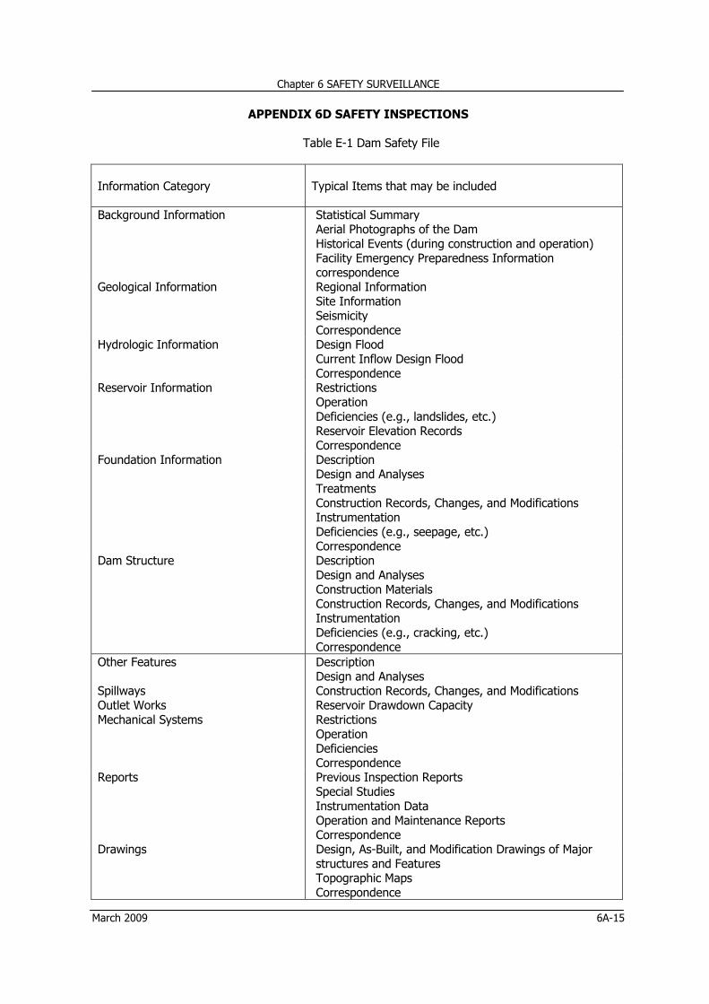
Dam Safety File or (Dam Data File) The Document comprising the complete history of the dam i.e. starting from the investigation, design, construction, operation and maintenance, surveillance and safety programme. This will be used to monitor the safe performance of the dam.
Dead Storage The storage that lies below the invert of the lowest outlet and that, therefore, can-not be withdrawn from the reservoir.
Deflection Linear deviation of the structure due to the effect of loads or volumetric changes.
Deforestation Deforestation means deliberate destruction of natural forests by felling and clearing of forests mainly for the purpose of logging and agricultural development.
Deformation Alteration of shape of dimension due to stress.
Drawdown The lowering of water surface level due to release of water from a reservoir.
Earth Dam or Earthfill Dam An embankment dam in which more then 50% of total volume is formed of compacted fine grained material obtained from a borrow area.
Embankment Fill material, usually earth or rock, placed with sloping sides and with a length greater than its height.
Embankment Dam Any dam constructed of excavated natural materials or of industrial waste materials.
Emergency Action Plan A predetermined plan of action to be taken to reduce the potential for property damage and loss of lives in an area affected by a dam break.
Emergency Spillway A spillway comprising a low embankment or a natural saddle designed to be overtopped and eroded away during a very rare and exceptionally large flood. i.e. a flood exceed IDF.
Engineer One who is professionally qualified and suitably experienced in relevant aspects of dam engineering to allow him to engage in some or all of the investigation, design, construction, repair and remedial work, operation and maintenance, surveillance and abandonment activities.
Expansion Joint A joint between parts of a concrete structure to allow for thermal changes to occur independently.
DID MANUAL Volume 9
x March 2009
Term
Definition
Face The external surface of a structure, e.g, the surface of a wall of a dam.
Failure The uncontrolled release of water from a dam.
Filter A band of granular material which is incorporated in an embankment dam and is graded (either naturally or by selection) so as to allow seepage to flow across or down the filter zone without causing the migration of material from zones adjacent to the filter.
Flood Routing The determination of the attenuating effect of storage on a flood passing through a valley, channel, or reservoir.
Foundation The material of the valley floor and abutments on which the dam is constructed.
Freeboard The vertical distance between the design flood level and the top of the dam.
Gallery A long, narrow passage inside a dam used for access, inspection, grouting, to drilling of drain holes.
Gravity Dam A dam constructed of concrete and / or masonry that relies on its weight for stability.
Grout A mixture of water and cement or a chemical solution that is forced by pumping into foundation rocks or joints in a dam to prevent seepage and to increase strength.
Grouting The injection under pressure of cement or other chemical mixture into the foundation or abutment of a dam to enhance watertightness and stability.
Hazard Threat; condition, which may result from an external cause (e.g. earthquake or flood), with the potential for creating adverse consequences.
Height of Dam The difference in level between the crest of the dam and the natural bed of the stream or watercourse at the downstream toe of the barrier, or the difference in level between the crest of the dam and the lowest elevation of natural ground surface along the toe.
Inflow Design Flood (IDF) Most server inflow flood (volume, peak, shape, duration, timing) for which a dam and associated facilities are designed.
DID MANUAL Volume 9
March 2009 xi
Term
Definition
Inspection Examination of current condition of the dam, its appurtenant structures and other related features, visually and by testing the equipment in operation or by operation.
Instrumentation Devices installed on and embedded within a dam to monitor the structural behavior during and after construction of the dam.
Large Dam Any dam which is above 15 meters in height or any dam between 10 and 15 meters in height which meets at least one of the following conditions: (a) the crest length is not less than 500 meters; (b) the capacity of the reservoir formed by the dam is not less than one million cubic meters; (c) the maximum flood discharge dealt with by the dam is not less than 2000 cubic meters per second; (d) the dam had specially difficult foundation problems; (e) the dam is of unusual design (Referable dams as designed herein are not necessarily large dams).
Leakage Uncontrolled loss of water by flow through a hole or crack.
Live Storage Volume of water available for use in irrigation, water supply or any other purpose.
Maintenance Work required to keep the existing works and systems (mechanical, electrical, hydraulic and civil) in a safe and functional condition.
Maximum Credible Earthquake (MCE) The severest earthquake that is believed to be possible at a site on the basis of geological and seismological evidence. It is determined by regional and local studies including a complete review of all historic earthquake data of events sufficiently nearby to affect the site, all faults in the area, and attenuations due to faults to the site.
Monitoring Checking and recording of the performance and behavioral trends of a dam and appurtenant structures by direct measurement, observation and measuring with devices or instruments that provide data from which are deduced such performance and behavioral trends.
Normal Pool Level For a reservoir with a fixed overflow sill the lowest crest level of that sill. For a reservoir whose outflow is controlled wholly or partly by moveable gates, siphons or other means, it is the maximum level to which water may rise under normal operating conditions, exclusive of any provision for flood surcharge.
DID MANUAL Volume 9
xii March 2009
Term
Definition
Outlet Works Combination of intake structure, conduits, tunnels, flow controls and energy dissipation devices to allow the release of water from a dam.
Operating Basis Earthquake (OBE) A hypothetical earthquake used for design purposes. A more moderate standard than the Maximum Credible earthquake, it is based on regional and local geology and seismology studies and is considered likely to occur during the life of the dam.
Owner Any person, company or authority owning the dam which is in existence or is being constructed or is proposed to be constructed.
Parapet or Parapet Wall A solid wall built along the top of a dam for ornament, for the safety of vehicles and pedestrians, or to prevent overtopping.
Piping The progressive developing of internal erosion by seepage, appearing downstream as a hole or seam discharging water that contains soil particles.
Pore Pressure The interstitial pressure of water within a mass of soil rock, or concrete.
Probable Maximum Flood (PMF) A flood that would result from the most severe combination of critical meteorologic and hydrologic conditions possible in the region.
Probable Maximum Precipitation (PMP) The maximum amount and duration of precipitation that can be expected to occur on a drainage basin.
Referable Dam Any artificial barrier, temporary or permanent, including appurtenant works which does or could impound, divert or control water and which either is 10 metres (33 feet) or more in height and has a storage capacity of more than 20,000 cubic metres (16 acre - feet), or has a storage capacity of 50,000 cubic meters (40 acre - feet) or more and is heigher than 5meters (16 feet).Any dam classified as referable dam by the above definition falls within the scope and control of this Manual.
Rehabilitation Work The work required to rehabilitate, strengthen, reconstruct, improve or modify an existing dam, appurtenant works, foundations, abutments or surrounding area to provide an adequate margin of safety (e.g. drainage, grouting, buttressing, post-tensioning, spillway or outlet works modification, etc).
DID MANUAL Volume 9
March 2009 xiii
Term
Definition
Relief Well Vertical wells or boreholes downstream of or in downstream shoulder of an embankment dam to collect and control seepage through or under the dam to reduce uplift pressure under or within the dam. A line of such wells forms a drainage curtain.
Reservoir The water body impounded by one or more dams or dikes, inclusive of its shores and banks and of any facility or installation necessary for its operation.
Riprap A layer of large uncoursed stones, broken rock, or precast blocks placed in random fashion on the upstream slope of an embankment dam, on a reservoir shore, or on the sides of a channel as a protection against wave action.
Rockfill Dam An embankment dam in which more than 50% of the total volume comprises compacted or dumped pervious natural or crushed rock.
Safety Review The review for assessing the safety of a dam, comprising a detailed study of structural, geotechnical, hydraulic and hydrologic design aspects and of the records and reports form surveillance activities, including the review of the safety in terms of current behavior of dam.
Seepage The interstitial movement of water that may take place through a dam, its foundation, or its abutments.
Slope (a) The side of a hill or mountain. (b) The inclined face of a cutting or canal or embankment. (c) Inclination from the horizontal. It is measured as the ratio of the number of units of horizontal distance to the number of corresponding units of vertical distance.
Slope Protection The protection of a slope against wave action or erosion.
Spillway A structure over or through which flood flows are
discharged. automatically where water level rises above the crest in case uncontrolled spillway, or by controlling the flow when it approaches the Normal Pool Level in case of gated spillway.
Stilling Basin A basin constructed so as to dissipate the energy of fast flowing water e.g. from a spillway or bottom outlet and to protect the river bed from erosion.
Storage Capacity The gross capacity of a reservoir from the river bed up to maximum controlled retention water level. i.e. Normal Pool Level and not upto designed flood level.
DID MANUAL Volume 9
xiv March 2009
Term
Definition
Surveillance The continued examination of the condition of a dam and its appurtenant structures and the review of operation, maintenance and monitoring procedures and results in order to determine whether a hazardous trend is developing or appears likely to develop.
Toe of Dam The junction of the downstream face of a dam with the ground surface, also referred to as downstream toe. For an embankment dam the junction of the upstream face with ground surface is called the upstream toe. Sometimes “heel” is used to define the upstream toe of a concrete gravity dam.
Trash Rack A screen located at an intake to prevent the ingress of debris.
Uplift The upward force of pore pressure considered to be acting in the foundation, on the base and throughout the dam.
Valve A device fitted to a pipeline or orifice in which the closure member is either rotated or move transversely or longitudinally in the waterway so as to control or stop the flow.
Vent Pipe A Pipe designed to provide air to the outlet conduit to reduce turbulence during release of water. Extra air is usually necessary downstream of constrictions.
Weir (a) A low dam or wall built across a stream to raise the upstream water level, termed fixed-crest weir when uncontrolled. (b) A structure built across a stream or channel for the purpose of measuring flow, sometimes called a measuring weir or gauging weir, and submerged weir.
CHAPTER 1 PLANNING
Chapter 1 PLANNING
March 2009 1-i
Table of Contents
Table of Contents ................................................................................................................... 1-i
List of Tables ......................................................................................................................... 1-ii
List of Figures ........................................................................................................................ 1-ii
1.1 Hazard Potential Classification System FEMA 33/MALAYSIA 1-2
1.2 Basic Information of DID Dams 1-4
1.3 Roles of DID/Govt and Consultants in Dam’s Life Cycle 1-6
List of Figures
Figure Description Page
1.1 Planning Activity Flow Chart 1-9
Chapter 1 PLANNING
March 2009 1-1
1 PLANNING
1.1 INTRODUCTION
1.1.1 Definition of Dam A dam is defined as an artificial barrier together with appurtenant works constructed for the purpose of holding water or any other fluid or silt across a natural water course or on the periphery of reservoir. For the purpose of this manual holding is envisaged that of water only, or silt. 1.1.2 Overview of the Engineering for dams Engineering of dams has evolved from crude works of the past in a distant era to increasingly complex present systems. Whereas ancient dam construction was an art based on simple trials and experimentation, the current accelerated progress contrasts sharply with gradual evolution of theories and practices in earlier centuries.
Earth dams built earlier used to be washed away by floods. However, the art of construction of dam kept on improving with time. Until about 1850, there were few rational criteria for design of dams. Notable progress was made in gravity dam engineering in nineteenth century, but it is only by 1940 that development of embankment construction by use of heavy earth moving equipment got through.
In spite of all the development in the scientific approach in design and construction of dams, the importance of dam safety could find its place only after the failure of Teton Dam in Idaho, USA, on June 5, 1976. The damage caused to the downstream property alone was estimated to be about ten times the original cost of the project. It was an embankment dam and the cause of failure was identified as piping through the embankment.
Dam safety guidelines were advanced by the International Committee on Large Dams (ICOLD) in their Executive Committee meeting No 59 (June 10-16, 1991). Earlier a Committee on the Safety of Dams was appointed by the (US) National Research Council’s Assembly of Engineering to review the USBR’s program on Safety of Dams 1977.
The guidelines for design of dams were published by the New York State Department of Environmental Conservation (DEC) in January 1985, which were revised in January 1989. The Australia National Committee On Large Dams (ANCOLD), the New Zealand Society On Large Dams (NZSOL), and others followed suit. 1.1.3 Need and Scope for Safety of Dams
Water stored in the reservoir created by construction of dam represents potential energy which is tantamount to potential hazard to downstream life, property and natural resources. The uncontrolled release of stored water consequent to failure of a dam can inflict catastrophic damage in the downstream area with a clean sweep of the life and property that comes in its way.
All engineering structures need to be planned, constructed, and kept under proper surveillance, maintained to keep them in safe serviceable condition. Failure of any type of structure can result in loss of life besides property, but the loss in case of any structure other than dams is limited to a localized area where as in case of dams, particularly those classified as “High Potential Hazard” and “ Significant Potential Hazard” dams, (Section 1.1.4), their loss becomes wide spread. That is where the difference lies.
Chapter 1 PLANNING
1-2 March 2009
As envisaged in the USCOLD Model Law published by the Committee On Large Dams, earlier in 1970, safety needs to be ensured at all stages of design, construction, operation, maintenance, enlargement, and modification, removal or abandonment. Virtually the dam safety concern takes its root at the planning stage when an alternate dam site or an alternate option to fall upon in the ultimate case of abandonment of the dam in service needs to be considered. Later on, consequent to the failure of Teton Dam, a Committee on the Safety of Dams was appointed by the (U.S) National Research Council’s Assembly of Engineering to review the USBR’s programme of Safety of Dams, 1977. Their technical recommendations are summarized as follows:
• Establish responsibility for dam safety programs within a single office. • Provide ample funds for dam safety activities, especially landslide surveillance, examination of
dams in high-risk locations, emergency preparedness, and geologic, seismologic and hydraulic data gathering.
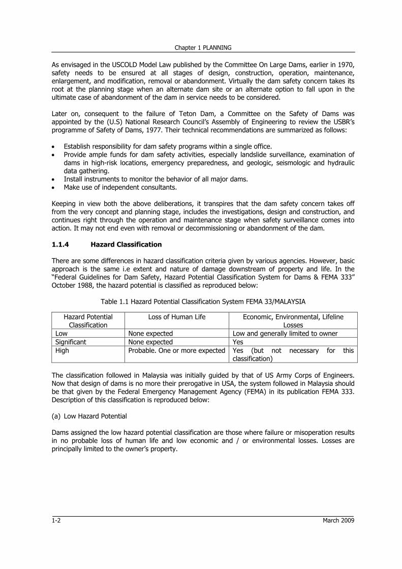
• Install instruments to monitor the behavior of all major dams. • Make use of independent consultants. Keeping in view both the above deliberations, it transpires that the dam safety concern takes off from the very concept and planning stage, includes the investigations, design and construction, and continues right through the operation and maintenance stage when safety surveillance comes into action. It may not end even with removal or decommissioning or abandonment of the dam. 1.1.4 Hazard Classification There are some differences in hazard classification criteria given by various agencies. However, basic approach is the same i.e extent and nature of damage downstream of property and life. In the “Federal Guidelines for Dam Safety, Hazard Potential Classification System for Dams & FEMA 333” October 1988, the hazard potential is classified as reproduced below:
Table 1.1 Hazard Potential Classification System FEMA 33/MALAYSIA
Hazard Potential Classification
Loss of Human Life
Economic, Environmental, Lifeline Losses
Low None expected Low and generally limited to owner Significant None expected Yes High Probable. One or more expected Yes (but not necessary for this
classification) The classification followed in Malaysia was initially guided by that of US Army Corps of Engineers. Now that design of dams is no more their prerogative in USA, the system followed in Malaysia should be that given by the Federal Emergency Management Agency (FEMA) in its publication FEMA 333. Description of this classification is reproduced below:
(a) Low Hazard Potential
Dams assigned the low hazard potential classification are those where failure or misoperation results in no probable loss of human life and low economic and / or environmental losses. Losses are principally limited to the owner’s property.
Chapter 1 PLANNING
March 2009 1-3
(b) Significant Hazard Potential Dams assigned the significant hazard potential classifications are those dams where failure or mis-operation results is no probable loss of human life but can impact other concerns. Significant hazard potential classification dams are often located in predominantly rural or agricultural areas but could be located in areas with population and signification infrastructure. (c) High Hazard Potential Dams assigned the high hazard potential classification are those where failure or mis-operation will probably cause loss of human life. 1.1.5 Existing DID Dams DID presently operates and maintains 15 dams (Table 1.2) of which three (3) are providing adequate irrigation water plus municipal/industrial water supply besides mitigating floods; five (5) are simply meeting the irrigation and municipal/industrial water demand; four (4) are supplying only municipal/industrial water besides serving the purpose of flood mitigation; and remaining three are meant for silt retention. Thirteen (13) of these dams are earthfill dams, one concrete faced rockfill dam and one (1) porous (rockfill) dam.
All of these dams are “Referable Dams” and 80% are categorized as large dams as defined in this manual. Gopeng Dam in Perak which is an earth dam 9 meters high, the capacity being negligible is the only exception. It serves the purpose of silt retention. Hazard classification of this dam is “Low”. Having been classified as a “Low Hazard - Small Dam”, its IDF (Section 2.1.2.) could be assumed as 100 - year Flood. However, being a referable dam, its Routine Inspection (Section 6.3.2) is required to be done.
Hazard classification of the silt retention and recreation dams is “Low”, except one silt retention dam, namely New Repas in Pahang which is a 20 meters high dam with 0.4 million cubic meters capacity; its hazard classification is “Significant”. Hazard classification of all other dams is “Significant” to “High”. New Repas dam having been classified as Significant Hazard “Dam”, could be designed for 50% PMF, if it was not a “Large Dam”. However, since it is a “Large Dam” it should be designed for PMF irrespective of the hazard classification.
Bukit Merah in Perak, constructed in the year 1906 i.e. 102 years hence, is the oldest DID dam. DID “Referable Dams” more than 40 years old include Padang Saga in Kedah, Old Repas in Pahang, New Repas in Pahang, and Labong in Johor. Evaluation of these dams should be carried out for rehabilitation and/or decommissioning, whether immediate or in foreseeable future.
Chapter 1 PLANNING
1-4 March 2009
Table 1.2 Basic Information of DID Dams
Chapter 1 PLANNING
March 2009 1-5
1.1.6 Participants’ Roles 1.1.6.1 General The participants in dam safety include:
• The dam Owner i.e. DID for the purpose of this manual and the Government of Malaysia who
are involved in the process from the beginning to the end. • The Consultants or the Technical Advisers whose role includes investigations, design, evaluation
and technical support in supervision of construction. • The Construction Contractors who undertake construction of the works • The Public who may advance the need and protect their social and environmental interests. 1.1.6.2 The Owner i.e. DID / Government DID is responsible for administration of its functions in accordance with the role it has to play (Table 1.3) throughout the life cycle of the dam, for which it is supposed to be well qualified and equipped with qualified and competent professional and technical staff. Thus it is of utmost importance that adequate resources (manpower and finance) at all phases of the dam’s project i.e. from planning till abandonment both at headquarters and state / district levels be provided.
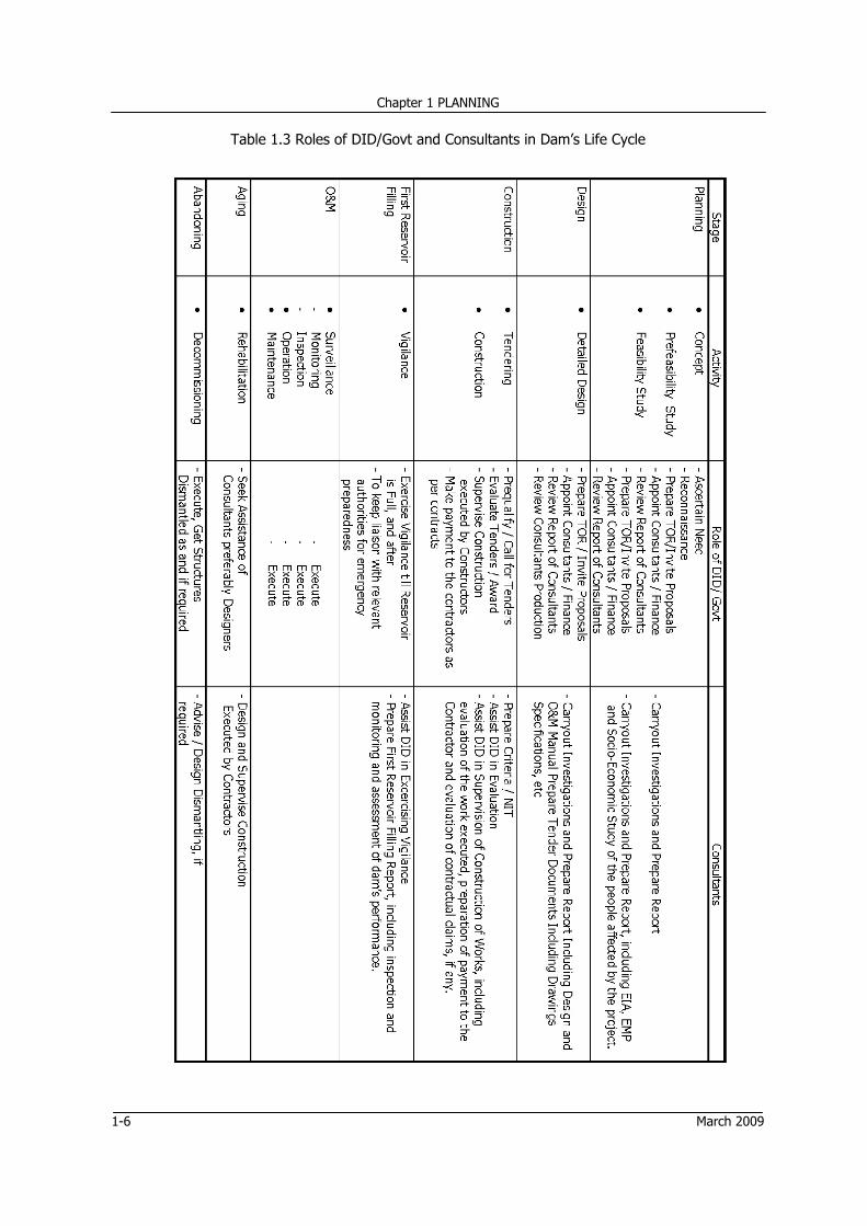
DID usually employs Consultants for investigations, design, safety reviews and the like and engages suitably qualified Contractors for construction and rehabilitation. The Consultants and the Contractors carry appropriate levels of responsibility and liability in performance of their duties under their respective terms and conditions of contract. The roles played by DID and the Consultants, throughout the life cycle of the dam are shown in Table 1.3 wherein the role played by the Contractors is also built in. It is elaborated in Sections 3.1.2 (c) and 3.4.2.
From the Table 1.3, it is evident that the skills required of DID relate to review and appraisal of the Consultants’ work, besides dealing with all administrative matters. The parties filling these roles play a key part in achieving safe and effective dams and often carry heavy responsibility for their advice or services. It is vitally important that they understand the extent of their roles and the boundaries of their responsibilities. For example it is not reasonable to expect the Consultants to certify the adequacy of its construction if they have not had adequate representation during construction or control over decision making on site. It is therefore usual practice and a recommendation of this Manual, that continuity of Consultants be maintained through design, construction and commissioning. 1.1.6.3 Expertise of Consultants The Consultants cover a wide scope of activities in the dam safety. Various aspects of investigation, evaluation, design and construction demand a high level of specialist expertise, particularly in the case of High Hazard Potential cases or technically complex dams. 1.1.6.4 Skills required of Contractors The contractors should possess requisite skills in construction management of hydraulic structures, quality control and assurance, design and detailing of mechanical equipment, etc. They would be required to engage some specialist sub-contractors.
Chapter 1 PLANNING
1-6 March 2009
Table 1.3 Roles of DID/Govt and Consultants in Dam’s Life Cycle
Chapter 1 PLANNING
March 2009 1-7
1.1.6.5 Public Members of the public most likely to become involved are those directly affected by the dam and its operation, and wider interest groups advancing a particularly environmental, social, cultural, or political perspective.
Members of the public with a direct interest often include those to whom the dam reservoir represents a potential hazard to life and property. Public safety is of primary importance and one of the reasons behind this Manual. The other participants must at all times recognize their duty of care of the Public and act de facto as agents for the well being of the Public. It is assumed that the public interest will be cared for by the Government. 1.1.7 Accessibility Accessibility plays an important role in the safety of the dams. Difficulty of access offers reluctance to routine inspection and maintenance, adversely affects the frequency of visits of the concerned, and obstructs the work in emergencies. Hence, provision of access roads is generally made in all projects as an essential part of the works.
1.2 THE PROCESS OF PLANNING 1.2.1 General The process consists of identifying the purpose or purposes of the dam, the opportunities available for the purpose, and development of alternative plans to meet the project requirements. It leads to selection of the final plan including the site of the dam and its size. 1.2.2 Levels of Study / Plan Formulation Plan formulation is an iterative process of comparing and selecting from alternate plans until the most acceptable plan is identified. It involves various levels of study, the sequence of which is as follows:
Each stage may involve some review and reconsideration of the results of the preceding stage because of new and more accurate information. Site locations and sizes of dams are usually established at the feasibility stage which supports and justifies an authorization for project construction, but some adjustments in sites and sizes are possible in the detail design investigation up to the point of making final designs for construction. Other levels of study following plan formulation include:
• Detail Design • Monitoring and Evaluation
Chapter 1 PLANNING
1-8 March 2009
Description of the first three levels of study is given below: 1.2.2.1 Inception / Concept Clearance or Preliminary Study
The preliminary study is generally based on reconnaissance which will identify needed data that may be expensive and may require considerable time to obtain.
The reconnaissance serves to identify the probable scope of a project plan, both as to geographic locations, numbers and types of project functions to be considered, and to show some indication of the magnitudes, and approximate sizes of structures. It should also disclose any major problem areas likely to be encountered. 1.2.2.2 Pre-feasibility Study
A Pre-feasibility study is the preliminary versions of a feasibility study ; taking into account all the physical, engineering, economic, social, and environmental factors, though with less accuracy. It is made with available data supplemented where most important with limited collection of new data, and by preliminary types of surveys.
If the pre-feasibility is completed in this brief form and indicates prospective project feasibility, it is then necessary to perform most of the plan formulation work in the beginning phases of the feasibility investigation. 1.2.2.3 Feasibility Study
The purpose of the feasibility study is to determine and demonstrate the soundness and justification of the project for implementation from the standpoint of objectives, accomplishments, benefits, costs, economic, and social and environmental considerations. Alternatively, the study should show reasons for lack of justification, if such proves to be the case.
1.2.2.4 Study of Alternatives
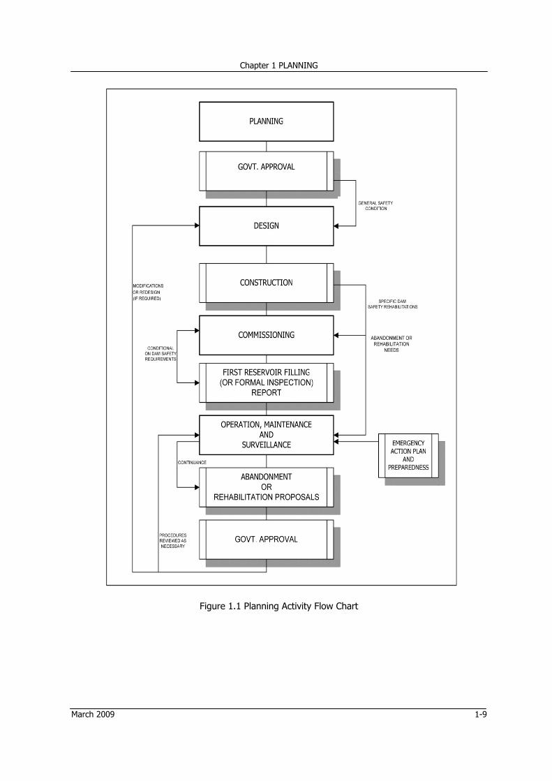
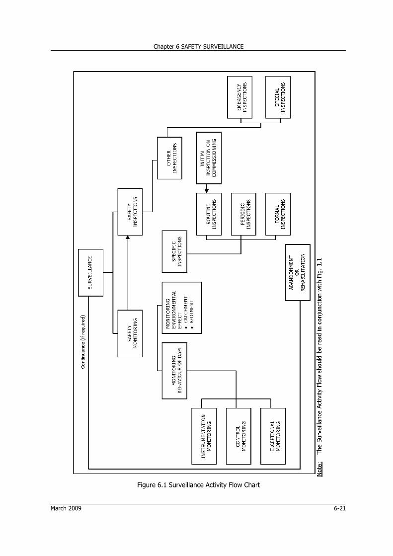
At all stages of planning there is need to make extensive examination of plan alternatives, amongst which there should be one to fall upon when the dam reaches the stage of abandonment. It is all the more important in case of reservoirs providing water for municipal and industrial purposes; irrigation supplies come next. 1.3 PLANNING ACTIVITY FLOW CHART Planning activity flow chart shown in Fig. 1.1 illustrates the dam safety planning process from inception to the abandonment of a dam and beyond.
Chapter 1 PLANNING
March 2009 1-9
Figure 1.1 Planning Activity Flow Chart
Chapter 1 PLANNING
1-10 March 2009
REFERENCES
[1] Department of Natural Resources (DNR), Indiana (2001) "General Guidelines for New Dams and Improvement to Existing Dams in Indiana", Division of Water, Indianapolis.
[2] Division of Water Resources, State of Colorado (June 1983), Dam Safety Manual, state Engineer’s Office, Denver, Colorado.
[3] FEMA # 333 (Oct. 1998), “Federal Guidelines for Dam Safety – Hazard Potential Classification for Dam”, Washington DC.
[4] Golze, A R (1977), "Handbook of Dam Engineering", Van Nostrand Reinhold Co., New York.
[5] New York State Department of Environmental Conservation, Jan 1985 (Revised Jan 1989) “Guidelines for Design of Dams”, Albany, New York.
[6] New Zealand Society On Large Dams (Nov. 2000), "New Zealand Dam Safety Guidelines", P O Box 12 - 241, Wellington New Zealand
[8] USBR (1988), "Training Aids For Dam Safety (TADS), Module: Documenting And Reporting Findings From A Dam Safety Inspection".
[9] Washington State Department of Ecology (July 1992), "Dam Safety Guidelines - Part III: An Owner's Guidance Manual", Dam Safety Section, Olympia, Washington.
[10] WCD Thematic Review Options Assessment IV.5 (Nov. 2000), "Operation, Monitoring and Decommissioning of Dams", Secretariat of the World Commission on Dams, Cape Town, South Africa.
CHAPTER 2 DESIGN
Chapter 2 DESIGN
March 2009 2-i
Table of Contents
Table of Contents .................................................................................................................... 2-i
List of Tables ......................................................................................................................... 2-ii
List of Figures ........................................................................................................................ 2-ii
2.7 DAM SAFETY PLANNING FLOW CHART ..................................................................... 2-21
Chapter 2 DESIGN
2-ii March 2009
List of Tables
Table Description Page
2.1 Minimum Factors of Safety for Earth and Rockfill Dams 2-7
2.2 Stability and Stress Criteria (Gravity Dams) 2-8
List of Figures Figure Description Page
2.1 Types of Earth Dam Section 2-9
2.2 Types of Rockfill Dam Section 2-10
2.3 Typical Dam Profiles Concrete Gravity Dams 2-11
2.4 Ogee Spillway Section 2-14
2.5 Side Channel Spillway 2-15
2.6 Typical Outlet through Embankment Dam with control at Upstream End 2-16
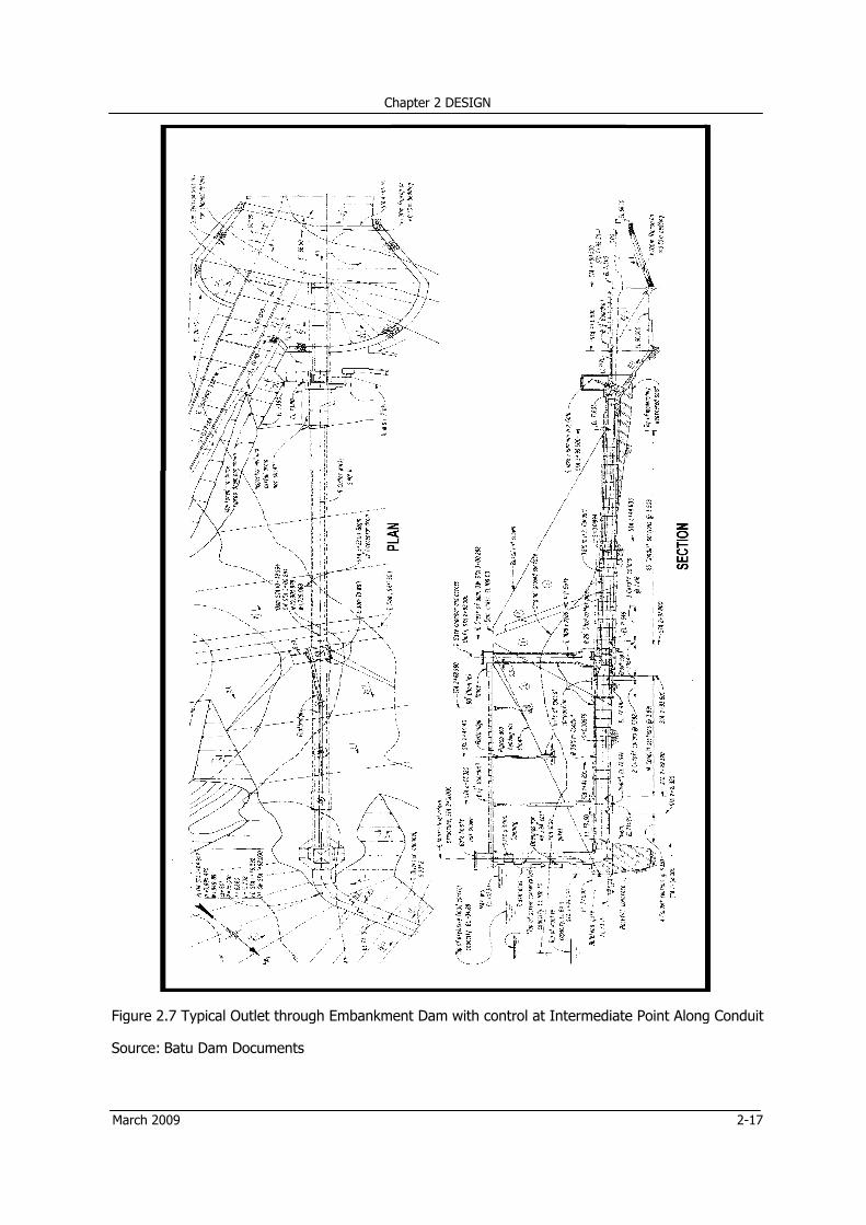
2.7 Typical Outlet through Embankment Dam with control at Intermediate Point Along Conduit 2-17
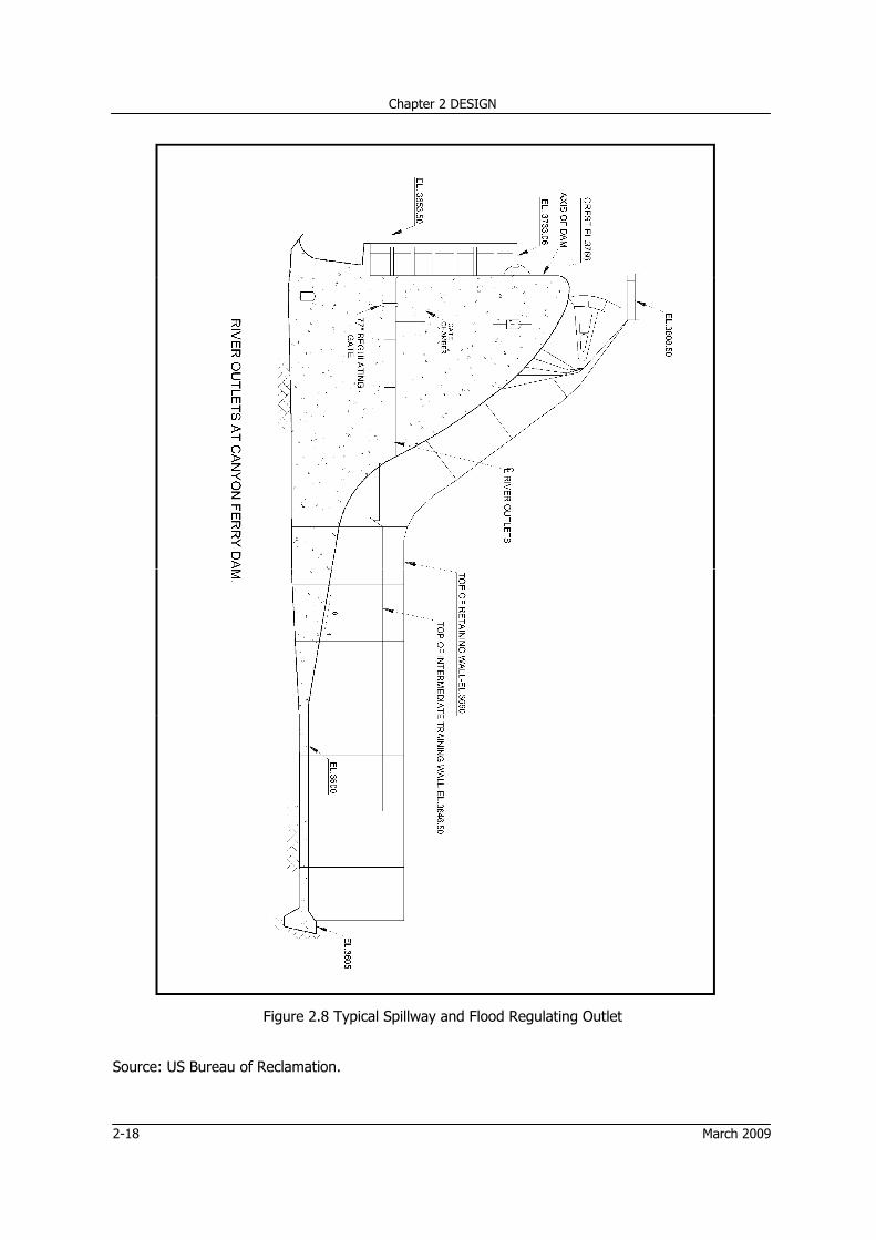
2.8 Typical Spillway and Flood Regulating Outlet 2-18
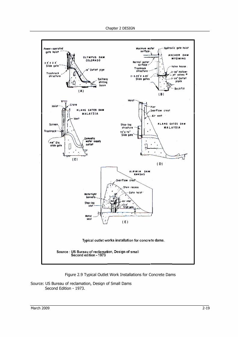
2.9 Typical Outlet Work Installations for Concrete Dams 2-19
2.10 Typical Main Dam Instrumentation Plan 2-22
2.11 Design Activity Flow Chart 2-23
2.12 Typical Spillway Instrumentation Plan 2-24
Chapter 2 DESIGN
March 2009 2-1
2 DESIGN
2.1 DESIGN PREVIEW 2.1.1 Geology 2.1.1.1 General The fundamental cause of many a dam failure is regarded to be a combination of geological factors and design decisions based on inadequate geological information, the well known failure of Teton Dam being an example. In words of Karl Terzaghi, “even the minor geological details” may be the cause of Engineer’s concern. The investigations including geological mapping, boring, drilling, test pits, test trenches, adits, test shafts, field and laboratory test etc should be carried out with utmost care so that all necessary information for design is made available; logging of bore holes, test pits, adits etc should be done such that no detail to define the materials is missed. 2.1.1.2 Seismicity Seismotectonic is an important aspect of dam safety studies though it may not be so in case of Malaysia. In this century Malaysia has been free of earthquakes of any significant consequence. A study of available literature indicates that earthquakes recorded in Malaysia during the past 150 years have been of low magnitude and may have probably been centered on Sumatra or the Andaman Sea. The case study of Bakun Dam, Malaysia, is referred to in the design of Beris Dam. It arrives at the design value of 0.10 g, facing calculated acceleration of 0.062 g at the given site. This is assumed to be the maximum value for Malaysia. However, the seismicity should be taken into consideration. If deemed necessary, Academic Science Malaysia may be contacted for any other specific dam that is designed in future. 2.1.1.3 Engineer’s Interest Of interest to the engineer for design of dams in general with reference to foundation on rock is the ensurance that the fractures, fault zones, steep faces, rough areas and weathered zones do not lead to seepage, loss of storage, and piping in the interface zone between foundation and fill. He, therefore, needs vital information regarding. • Joints • Faults • Fissures • Fractions • Bedding plans, and • Crevices, cavities or other openings
The above information, which is needed for all types of dams in common, is sufficient for earth dams. But for rockfill dams the requirement of control of leakage, piping and settlement is more stringent, besides need of prevention of development of friction between abutment and dam foundation to ensure safety against sliding. Hence knowledge of:
Chapter 2 DESIGN
2-2 March 2009
• Hardness and • Erosion resistance is also necessary. However, rocks in foundations of concrete gravity dams need the maximum attention, with further information regarding: • Deformation modulus of the rocks • Shear strength and • Foundation configuration including slope
2.1.1.4 Areas of Concern The main areas of concern for dam safety include:
• Landsliding • Stability of slopes around reservoir i.e. rim • Stability of abutments • Competence of foundation materials • Seepage of foundation • Evaluation of seismic effects
The investigations and analyses are required to be done both in phase I - design and construction; and phase II – operation and maintenance of the dams. All work undertaken in the geological and geotechnical investigation stage should be properly recorded and presented in a comprehensive report. This will enable the designer to define the extent of any further work required prior to finalizing the design. Investigations are generally continued through the construction period as the foundations become fully exposed and the extent of any foundation work, such as grouting, is recognized. Consequently, investigative reports need to be updated and amended as construction proceeds. When construction is complete, a full and comprehensive report should be available as a reference for surveillance of the dam and subsequent safety reviews. 2.1.1.5 Use of the Information for Dam Safety
For the safety of the dams, the engineer will use the information furnished to him for ensuring in design that in case of earthfill dams:
• The rock mass in foundation and abutments is homogeneous and compact; • Faults, fractures, weathering, steepness, foundation finish, etc, do not cause piping through the
foundation and earthfill interface. (The impervious zone and the internal drainage system downstream of the impervious zone invite special attention).
• Erosion giving rise to excessive water losses, leakage and / or excessive uplift pressures, caused by fractures, cavities, roughness and bedding planes, is adequately guarded against.
In case of rockfill dams he has to ascertain that:
• Sliding does not take place for want of development of friction. For foundation of gravity dams, he makes sure that he gets sufficient data for determination of:
• Deformation modulus of each type of foundation material within and around the loaded area,
taking into account effect of joints, faults and fissures. • Shear strength by way of field and laboratory tests including that for joints, joint fillings, faults,
shears, seams, bedding, foliation and other geological features likely to influence stability.
Chapter 2 DESIGN
March 2009 2-3
2.1.2 Hydrology 2.1.2.1 General Like geology, hydrology plays an important role in ascertaining the safety of dam. About a third of all dam failures have been caused because of overtopping of the dam due to inadequate spillway capacity resulting from under-estimate of spillway design flood. Overtopping takes place when the reservoir water level rises above the crest level of the dam. Worst affected by overtopping are usually the embankment dams which more often than not result in breaches washing away the dams. Gravity dams when overtopped can overturn if the design does not take the worst condition of probable reservoir water level into consideration; depending upon the intensity and duration of the rain. The gravity dam may also end in failure consequent to erosion of foundation and abutments leading to sliding or overturning. An emergency spillway provided with earth fuse-plug as that at Timah Tasoh Dam can result in erosion of the ground over which it is constructed. In case of an exceptionally high flood of long duration the erosion may progress towards the embankment with probability of its failure. The hydrologic concerns do not end with design and construction. The watershed characteristics may change any time during the life cycle of the dam consequent to afforestation, agricultural development, urbanization, mining, or any other development affecting the assessment of inflow. Besides, the development may also warrant review of the hazard classification. 2.1.2.2 Inflow Design Flood Criteria of inflow design flood should be the same for both new dams as well as existing dams, though changes in catchment characteristics and land use should be considered in case of existing dams. PMF is the upper limit of IDF which should be invariably adopted in case of high risk classification of dams and dams providing water supply for domestic purposes. The lower limit is generally accepted as a 100 - year flood. Intermediate values assumed for significant hazard dams by various agencies are different. In most cases, 50% of PMF for IDF is considered to be good enough for significant hazard classification. However PMF governs the design of all large dams irrespective of hazard classification. Assuming overtopping to be the most common cause of failure of a dams related to hydrologic conditions, the quantitative assessment of the risk may be based on the damage caused by floods of various frequencies on the downstream. The situation downstream is analyzed on basis of the areas flooded downstream with and without dam failure. Dambreak analysis is conducted for the purpose and the dambreak flood is routed downstream to the point where there is no threat due to flood. The dambreak analysis is first done assuming failure with reservoir water level at spillway crest. It is repeated for various reservoir levels between the reservoir level at spillway crest and the reservoir water level at PMF. The IDF is selected on basis of the incremental impacts on downstream areas. The frequency of flood at which further damage is not acceptable should be taken as the IDF.
2.1.2.3 Reservoir Flood Routing Reservoir routing of the PMF inflow or the inflow design flood is carried out to determine the design discharge of the spillway and maximum water level in the reservoir.
Chapter 2 DESIGN
2-4 March 2009
The maximum allowable water elevation in flood routing analysis should not exceed the designed spillway surcharge elevation, so that the designed minimum freeboard is not encroached upon. 2.1.2.4 Existing Dams - Remedial Action On hydrologic review of existing dams, if any inadequacies are disclosed, remedial action should come into play. Both structural and nonstructural measures should be considered. From amongst the structural measures those easy to implement, without introducing new problems, are: • Increasing the discharge capacity by providing an emergency type spillway with crest level lower
than the top of the dam such that it gets washed out when overtopped: This depends on availability of suitable site for the purpose.
• Raising the height of the dam, thereby increasing the discharge capacity of the spillway
For this geological conditions downstream and design energy dissipation devices should be examined. Besides effect of raising the water elevation on appurtenant structures of the dam, additional submergence by the reservoir and downstream hazard should be re-assessed.
Other structural measures could be: • Diverting some runoff upstream:
This depends upon topography of the watershed.
• Modifying the dam to permit overflow:
It is not suitable for an embankment dam. Stability in overturning and sliding should be examined for concrete dams.
Nonstructural measures include: • Review and revision of Emergency Action Plan (EAP):
This requires enhancement of warning system including smartness in transmission of the relevant data. Despite all the care, this is likely to be ineffective at times.
• Modifying Project Operations:
This is too complex to implement satisfactorily.
• Modifying Downstream Areas:
Its feasibility is doubtful.
From the above discussions, it can be said that none of the nonstructural measures is convincing. If no remedial measure is found to be feasible, decommissioning and dismantling of the dam appears to be the last resort, in which case an alternative needs to be deviced to serve the purpose for which the dam was constructed.
Chapter 2 DESIGN
March 2009 2-5
2.2 DESIGN OF DAMS 2.2.1 General General Factors which should be considered during the design of a dam include: a) Physical characteristics • dam type • location and alignment • size and shape • appurtenant works b) Geotechnical information • material properties and availability • foundation properties and treatment • geological characteristics • seismic loadings c) Hydraulic aspects • type of spillway, means of flow control and energy dissipation • hydrological characteristics • hydraulic design and water loadings • stream diversion requirements • flood mitigation capacity
d) Stability • Structural capacity of principle elements e) Construction methods and sequencing • including watercourse diversion requirements during construction f) Operational aspects • operational complexity and reliability • requirements for ongoing monitoring • technical capability and availability of operations personnel g) Environmental aspects • environmental impacts including the effects of storage and barriers • effect on upstream and downstream areas • magnitude of downstream releases The factors that may affect the likelihood of a dam failure related to design, are: • Difficult, unusual or undisclosed foundation conditions. • Quality of construction materials, or improper use of construction materials. • Neglect of some design criteria • Landslides in the reservoir area, not anticipated, or not taken into consideration. • Neglect of consideration of forestry operations in the catchment and the risk of debris.
Chapter 2 DESIGN
2-6 March 2009
Other factors such as proximity of active faults and proximity to volcanic Hazards, though of relevance in general are not relevant for Malaysia.
The types of dam described in this manual as follows are based on classification by materials, and include:
• An embankment dam (earthfill or rockfill) • A concrete dam (gravity) The arch and buttress dams are the types which are most uncommon; these types are excluded. 2.2.1.1 Embankment Dams The Criteria set forth by U.S Corps of Engineers (Manual U.S.Corps,1971) and others to meet the basic design requirements can be expressed as follows:
• Combined with design of spillway guarding against floods, sufficient freeboard must be provided
so that the dam is not overtopped due to action of waves, including an allowance for settlement of the foundation and embankment.
• Seepage waters including those through the embankment, foundation, and abutments should be satisfactorily controlled and disposed of so as to prevent excessive uplift pressures, piping, sloughing, removal of soluble materials, or erosion of material by loss into cracks, joints, and cavities. Rate of seepage may also need to be limited.
• Foundation deformation and settlements over abutment irregularities and irregularities elsewhere should be taken care of such that they may not create tensile strains causing visible cracks consequent to leakage.
• Upstream and downstream slopes should be structurally stable under all condition of construction and reservoir operations.
• In case of earth dams, phreatic surface should be prevented from reaching the downstream slope and seepage waters should be satisfactorily disposed of.
• Again in case of earth dams, upstream slope should be protected against wave action, and downstream slope against climatic conditions.
• Earthquake forces and their effect on the dam must not be underestimated in stability analysis. Specific considerations for rockfill dams are as follows:
• If founded on rock, the strength of the foundation rock should be comparable to the strength of
the rockfill. Else, stability analyses should be based on weak foundation. • Rockfill dams should not be placed on low density alluvial deposits. • Dense, high strength alluvial, moranial or similar granular material foundations are considered to
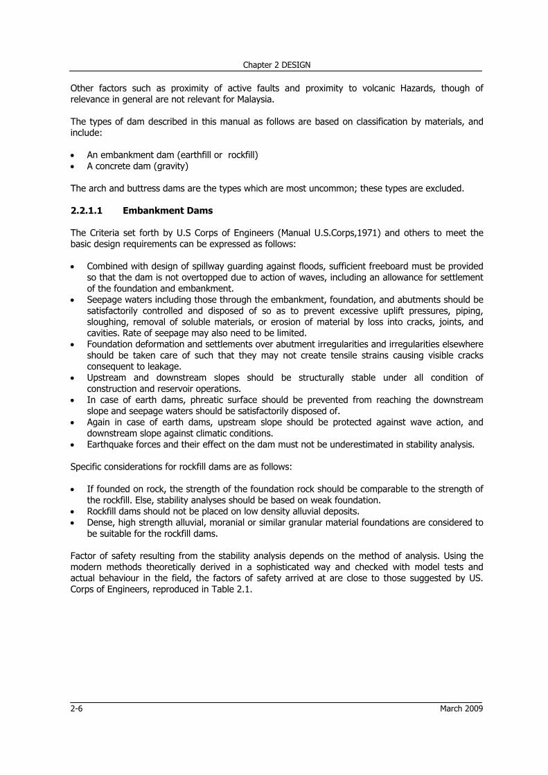
be suitable for the rockfill dams. Factor of safety resulting from the stability analysis depends on the method of analysis. Using the modern methods theoretically derived in a sophisticated way and checked with model tests and actual behaviour in the field, the factors of safety arrived at are close to those suggested by US. Corps of Engineers, reproduced in Table 2.1.
Chapter 2 DESIGN
March 2009 2-7
Table 2.1 Minimum Factors of Safety for Earth and Rockfill Dams
Case No Design Condition
Minimum Factor of Safety
Shear Strength Remarks
I End of Construction
1.32) Q or S3 Upstream and down stream slopes
II Sudden drawdown from maximum pool
1.04) R. S Upstream slope only. Use composite envelope
III Sudden drawdown from spillway crest
1.24) R. S Upstream slope only. Use composite envelope
IV Partial pool with steady seepage
1.5 (R+S)/2 for R<S for R>S
Upstream slope only. Use intermediate envelope
V Steady seepage with maximum storage pool
1.5 (R+S)/2 for R<S for R>S
Downstream slope only. Use intermediate envelope
VI Earthquake (Cases I, IV & V with seismic loading)
1.0 Refer Note (5) below
Upstream and downstream slopes
Notes: a) Not applicable to embankments on clay shale foundations; higher safety
factors should be used for these conditions. b) For embankments over 50 feet high on relatively weak foundation use
minimum factor of safety of 1.4 c) In zone where no excess pore water pressures are anticipated use S
strength d) The safety factor should not be less than 1.5 when drawdown rate and pore
water pressures developed from flow nets are used in stability analyses e) Use shear strength for case analyzed without earthquake Symbols: Term Q Shear test for specimen tested at constant water content (unconsolidated-
undrained). S Shear test for specimen consolidated without restriction of change in water
content (consolidated drained).
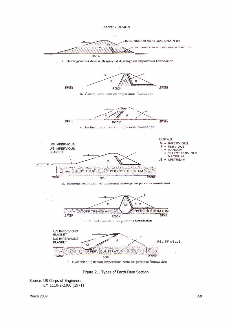
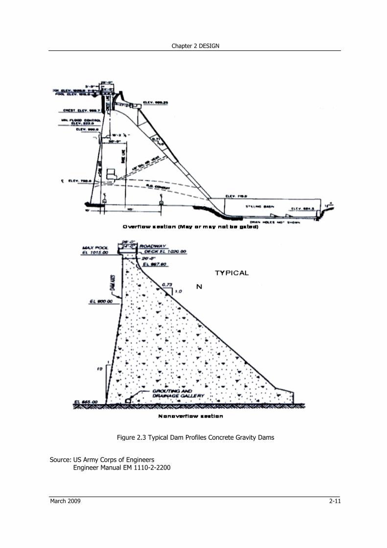
Fig 2.1 shows some typical earth dam sections, and Fig 2.2 shows some typical rockfill dam sections. 2.2.1.2 Concrete Gravity Dams Typical concrete gravity dam sections in vogue are shown in Fig. 2.3. The Section is basically triangular, with some modifications, as stated below: • Upstream face is usually made vertical to concentrate the weight of the structure at the
upstream face for resisting reservoir water pressure. A batter may, however, be provided to make it safe in sliding.
• The downstream face has usually a constant slope from top to bottom. However, it is made
vertical for some height at the top of the nonoverflow section to provide additional thickness required at crest for roadway or other access needs.
Chapter 2 DESIGN
2-8 March 2009
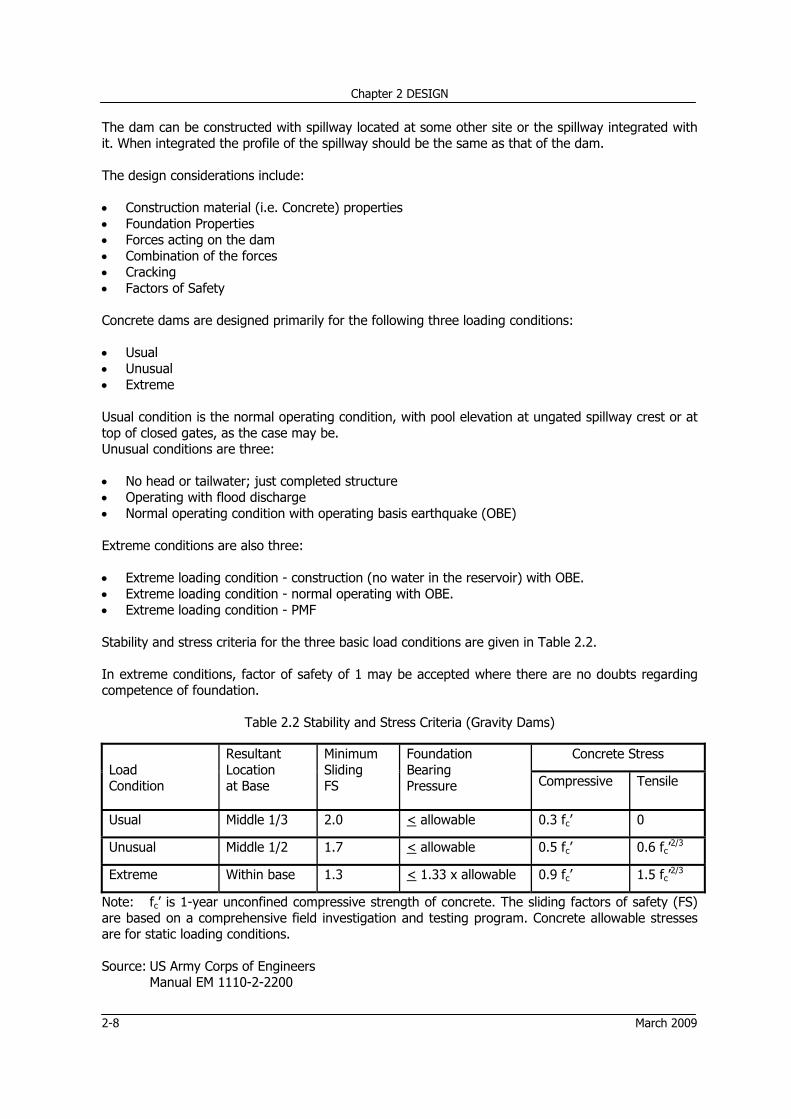
The dam can be constructed with spillway located at some other site or the spillway integrated with it. When integrated the profile of the spillway should be the same as that of the dam. The design considerations include: • Construction material (i.e. Concrete) properties • Foundation Properties • Forces acting on the dam • Combination of the forces • Cracking • Factors of Safety
Concrete dams are designed primarily for the following three loading conditions: • Usual • Unusual • Extreme Usual condition is the normal operating condition, with pool elevation at ungated spillway crest or at top of closed gates, as the case may be. Unusual conditions are three:
• No head or tailwater; just completed structure • Operating with flood discharge • Normal operating condition with operating basis earthquake (OBE)
Extreme conditions are also three:
• Extreme loading condition - construction (no water in the reservoir) with OBE. • Extreme loading condition - normal operating with OBE. • Extreme loading condition - PMF Stability and stress criteria for the three basic load conditions are given in Table 2.2. In extreme conditions, factor of safety of 1 may be accepted where there are no doubts regarding competence of foundation.
Table 2.2 Stability and Stress Criteria (Gravity Dams)
Extreme Within base 1.3 < 1.33 x allowable 0.9 fc’ 1.5 fc’2/3
Note: fc’ is 1-year unconfined compressive strength of concrete. The sliding factors of safety (FS) are based on a comprehensive field investigation and testing program. Concrete allowable stresses are for static loading conditions. Source: US Army Corps of Engineers
Manual EM 1110-2-2200
Chapter 2 DESIGN
March 2009 2-9
U/S IMPERVIOUS BLANKET U/S IMPERVIOUS BLANKET
U/S IMPERVIOUS BLANKET U/S IMPERVIOUS BLANKET
Figure 2.1 Types of Earth Dam Section
Source: US Corps of Engineers EM 1110-2-2300 (1971)
Chapter 2 DESIGN
2-10 March 2009
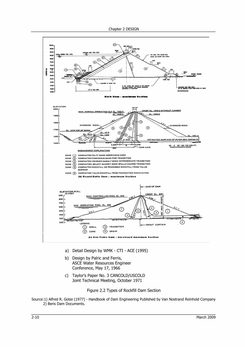
DIVERSION
a) Detail Design by WMK - CTI - ACE (1995)
b) Design by Palric and Ferris, ASCE Water Resources Engineer Conference, May 17, 1966
c) Taylor’s Paper No. 3 CANCOLD/USCOLD Joint Technical Meeting, October 1971
Figure 2.2 Types of Rockfill Dam Section
Source:1) Alfred R. Golze (1977) - Handbook of Dam Engineering Published by Van Nostrand Reinhold Company 2) Beris Dam Documents.
CChapter 2 DESII
March 2
Source
2009
: US Army CoEngineer M
Figure 2
orps of EnginManual EM 11
2.3 Typical Da
neers 110-2-2200
am Profiles C
GN
Concrete Gra
avity Dams
2-11
Chapter 2 DESIGN
2-12 March 2009
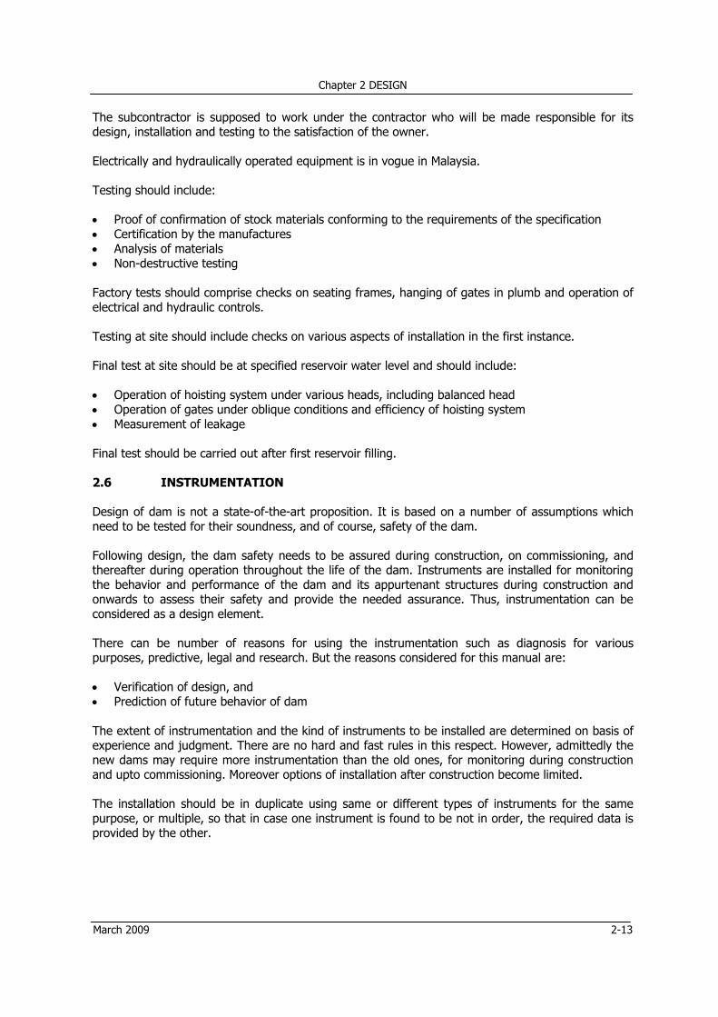
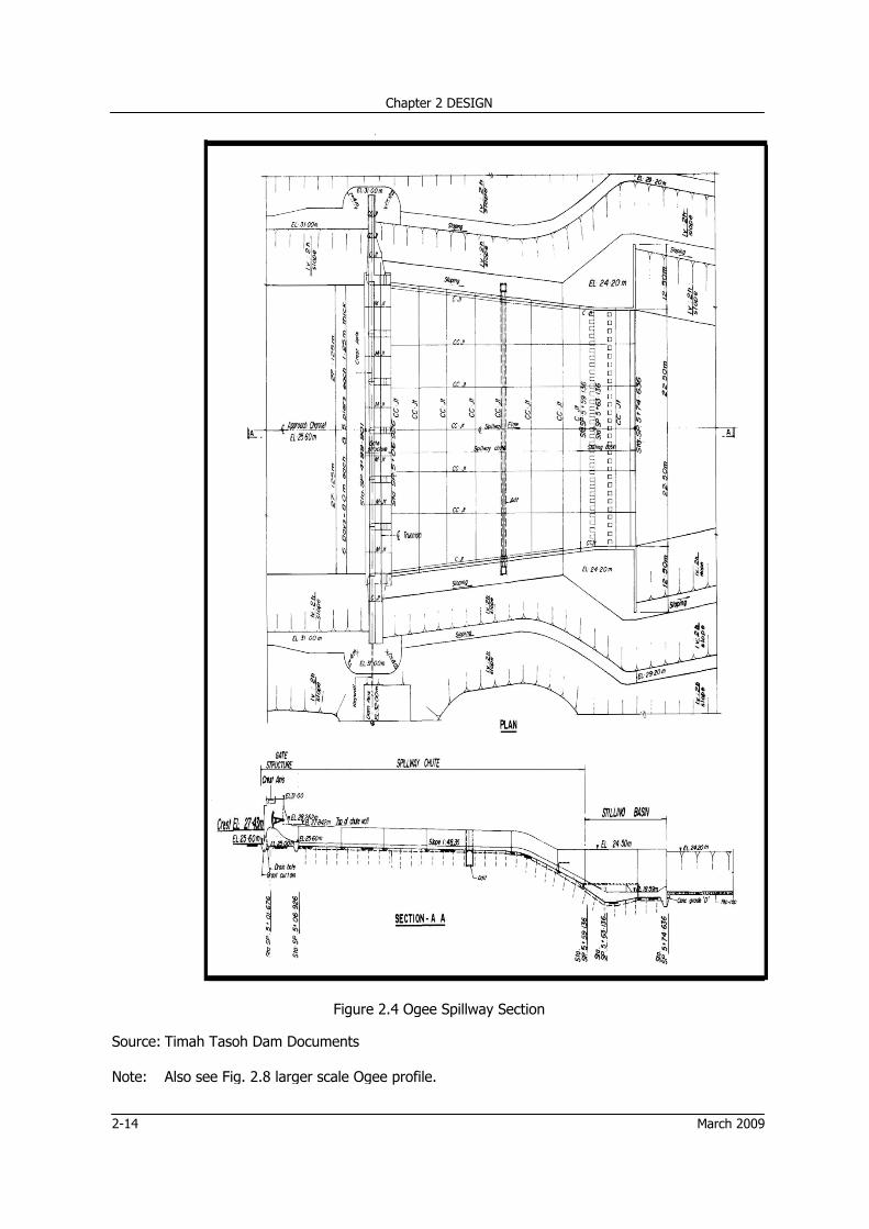
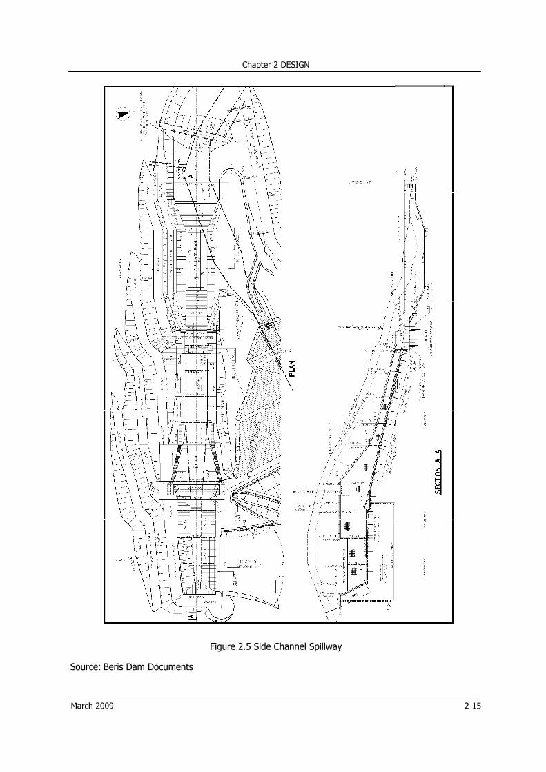
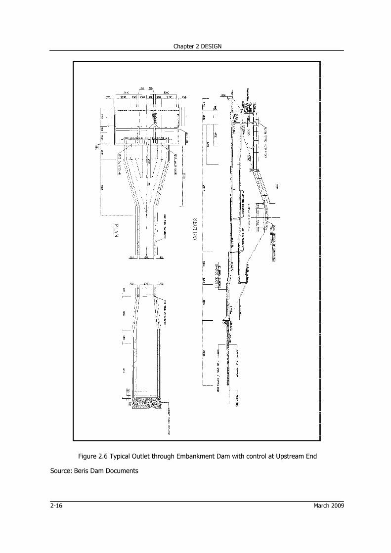
2.3 SPILLWAYS Spillways are designed to release surplus floodwater that exceeds the capacity of the reservoir. The safety of the reservoir will be in danger if the excess is not satisfactorily disposed of. Requirements of a safe spillway include: • Proper location • Sufficient flood discharge capacity • Appropriate hydraulic design • Adequate structural design The location of the spillway should be such that the disposal of floods does not erode or undermine the downstream toe of the dam. Flood discharge capacity is the most important aspect of spillway design as many failures of the dams are attributed to inadequate spillway capacity. This demands accuracy in estimates of floods and care in selection of IDF, which are discussed in Sections 1.1.4 and 2.12.2. Having adequately evaluated the risk downstream and having assured the accuracy of IDF, the safety of the spillway structure demands that: • It is structurally safe for full range of flood releases • Its operation equipment and system is highly reliable, if the spillway is controlled. Typical spillway sections are shown in Figures 2.4 and 2.5. A larger scale Ogee spillway section with flood regulating outlet is shown in Fig. 2.8. 2.4 OUTLET WORKS The functions of an outlet may include flood control, water supply, irrigation, or a combination thereof. Low flow requirements for downstream users other than the project beneficiaries may also be one of the functions in combination.
When the conduit passes through the embankment, gates and /or valves to control the flow are preferably located in an intake tower in the reservoir. Placement of the controls at the outlet portal are best avoided due to probability of rupture of the conduit at full reservoir head.
Consideration for conduits should primarily be as follows: • In case of conduits or tunnels flowing under pressure for entire length or a part of it, dissipating
devices similar those in case of spillway should be provided. • The conduits should slope downstream to ensure drainage. • The conduit joints should be watertight to prevent leakage. Typical outlet sections are shown in Figures 2.6 to 2.9. 2.5 HYDROMECHANICAL EQUIPMENT The hydromechanical equipment installed on dams usually includes various types of gates such as bulkhead gates, vertical lift gates and radial gates, valves, trashracks, and water level recorders. In addition to these conventional installations, telemetry is gaining ground in Peninsular Malaysia.
The design, provision, installation and testing of the equipment should be carried out by an approved well established subcontractor or manufacturer for confidence in design.
Chapter 2 DESIGN
March 2009 2-13
The subcontractor is supposed to work under the contractor who will be made responsible for its design, installation and testing to the satisfaction of the owner.
Electrically and hydraulically operated equipment is in vogue in Malaysia. Testing should include: • Proof of confirmation of stock materials conforming to the requirements of the specification • Certification by the manufactures • Analysis of materials • Non-destructive testing Factory tests should comprise checks on seating frames, hanging of gates in plumb and operation of electrical and hydraulic controls.
Testing at site should include checks on various aspects of installation in the first instance.
Final test at site should be at specified reservoir water level and should include:
• Operation of hoisting system under various heads, including balanced head • Operation of gates under oblique conditions and efficiency of hoisting system • Measurement of leakage Final test should be carried out after first reservoir filling. 2.6 INSTRUMENTATION Design of dam is not a state-of-the-art proposition. It is based on a number of assumptions which need to be tested for their soundness, and of course, safety of the dam.
Following design, the dam safety needs to be assured during construction, on commissioning, and thereafter during operation throughout the life of the dam. Instruments are installed for monitoring the behavior and performance of the dam and its appurtenant structures during construction and onwards to assess their safety and provide the needed assurance. Thus, instrumentation can be considered as a design element.
There can be number of reasons for using the instrumentation such as diagnosis for various purposes, predictive, legal and research. But the reasons considered for this manual are:
• Verification of design, and • Prediction of future behavior of dam The extent of instrumentation and the kind of instruments to be installed are determined on basis of experience and judgment. There are no hard and fast rules in this respect. However, admittedly the new dams may require more instrumentation than the old ones, for monitoring during construction and upto commissioning. Moreover options of installation after construction become limited.
The installation should be in duplicate using same or different types of instruments for the same purpose, or multiple, so that in case one instrument is found to be not in order, the required data is provided by the other.
2-14
Source Note:
: Timah Taso
Also see Fig
C
oh Dam Docu
g. 2.8 larger
Chapter 2 DESI
Figure 2.4
uments
scale Ogee
I
4 Ogee Spillw
GN
profile.
way Section
March 2009
CChapter 2 DESII
March 2
Source
2009
: Beris Dam
Documents
Figure 2.5
5 Side Chann
GN
nel Spillway
2-15
2-16
Source
Figure 2.6
: Beris Dam
C
6 Typical Out
Documents
Chapter 2 DESI
tlet through
IGN
Embankment Dam with c
control at Up
M
pstream End
arch 2009
CChapter 2 DESII
March 2
Figure
Source
2009
2.7 Typical O
: Batu Dam D
Outlet throug
Documents
gh Embankm
ment Dam wit
GN
th control at
Intermediate
e Point Along
2-17
g Conduit
Chapter 2 DESIGN
2-18 March 2009
Figure 2.8 Typical Spillway and Flood Regulating Outlet
Source: US Bureau of Reclamation.
CChapter 2 DESII
March 2
Source
2009
: US Bureau Second Edi
Figure 2.9 T
of reclamatition - 1973.
Typical Outlet
on, Design o
t Work Insta
of Small Dam
GN
llations for C
ms
Concrete Dam
ms
2-19
Chapter 2 DESIGN
2-20 March 2009
In general the measurement devices can be classified as: (a) Pressure Measuring Devices (b) Seepage Measuring Devices (c) Internal Movement Measuring Devices (d) Special Measuring Devices, Vibrating Wire Type such as for:
- Measuring Movement of Joints or Cracks - Measuring Strains in Concrete
The types of instruments commonly used for the above purposes are described as follows:
(a) Pressure Measuring Devices Basically piezometer is the device used to measure pore pressure within, around and under the embankments. The most common types of piezometers currently used include:
• Standpipe Piezometers, Casagrande type • Vibrating Wire Electrical Piezometers While being simple and reliable, standpipe piezometers are unsuitable for placement in materials of low permeability where a quick response time is required. The advantage of electrical piezometer lies in the very short response time and hence are helpful in accurate measurement of pore pressure in fine grained soil. Vibrating wire piezometers have great superiority because the length of leads does not have any role in measurements and hence instruments can have much longer leads if required by site conditions. (b) Seepage Measuring Devices Seepage measuring devices are used to measure seepage or leakage through, around and under the embankments.
The commonly used device is the weir which is one of the oldest, simplest, and most reliable devices. The weirs may be V-north is the mostly favoured device for seepage measurement because of accuracy of the measurement for small flows, which should normally be the case. The accuracy is consequence of greater head of flow as compared to that in case of other types of weirs.
(c) Internal Movement Measuring Devices Internal movement measurement devices are used to measure vertical movements e.g. embankment settlement and foundation settlement and lateral movement. There are a number of devices used for the purpose the most popular amongst them being:
The D.F.S.D provides a continuous profile data to better than ± 15mm elevation over tubing length of 1km. Its automatic operation has greater advantages. The inclinometer is a simpler devise for measurement of vertical movement. (d) Surface Movement Devices Surface movement devices commonly used are simple monuments installed on the surface of embankment dams, or abutments. On concrete structures, measurement points engraved on surface
Chapter 2 DESIGN
March 2009 2-21
or embedded in concrete can serve the purpose. They are used as reference points for measurement of movement in any plane and direction. (e) Special Measuring Devices
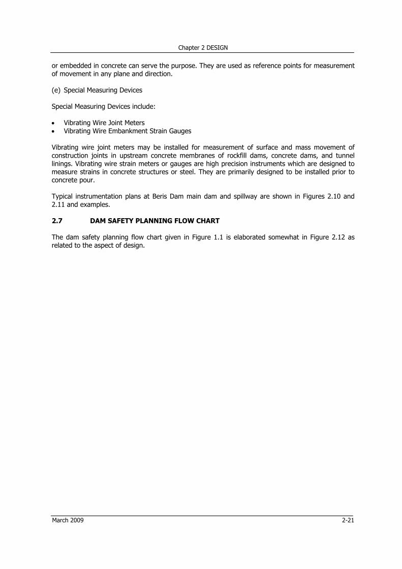
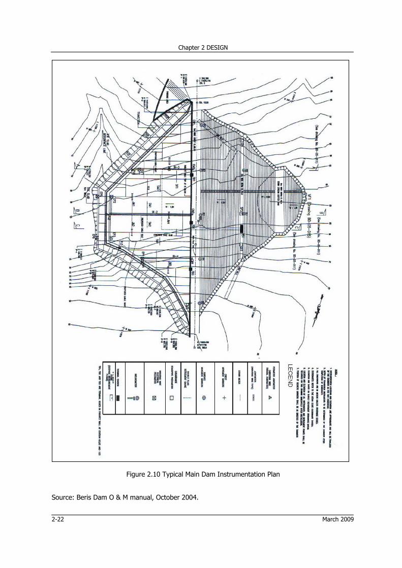
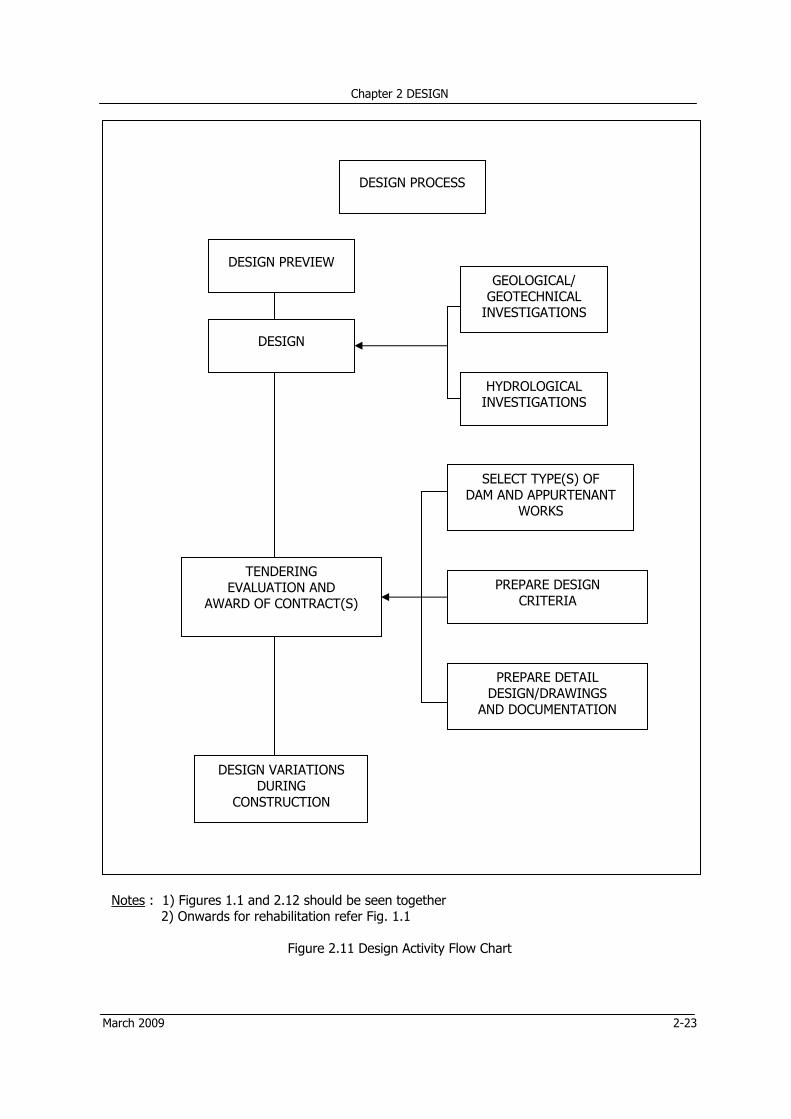
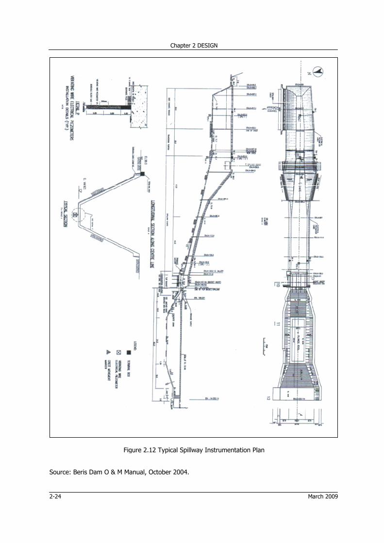
Vibrating wire joint meters may be installed for measurement of surface and mass movement of construction joints in upstream concrete membranes of rockfill dams, concrete dams, and tunnel linings. Vibrating wire strain meters or gauges are high precision instruments which are designed to measure strains in concrete structures or steel. They are primarily designed to be installed prior to concrete pour. Typical instrumentation plans at Beris Dam main dam and spillway are shown in Figures 2.10 and 2.11 and examples. 2.7 DAM SAFETY PLANNING FLOW CHART The dam safety planning flow chart given in Figure 1.1 is elaborated somewhat in Figure 2.12 as related to the aspect of design.
Chapter 2 DESIGN
2-22 March 2009
Figure 2.10 Typical Main Dam Instrumentation Plan
Source: Beris Dam O & M manual, October 2004.
Chapter 2 DESIGN
March 2009 2-23
DESIGN PROCESS
DESIGN PREVIEW GEOLOGICAL/
GEOTECHNICAL INVESTIGATIONS
DESIGN
HYDROLOGICAL INVESTIGATIONS
SELECT TYPE(S) OF DAM AND APPURTENANT
WORKS
TENDERING EVALUATION AND
AWARD OF CONTRACT(S) PREPARE DESIGN
CRITERIA
PREPARE DETAIL DESIGN/DRAWINGS
AND DOCUMENTATION
DESIGN VARIATIONS DURING
CONSTRUCTION
Notes : 1) Figures 1.1 and 2.12 should be seen together 2) Onwards for rehabilitation refer Fig. 1.1
Figure 2.11 Design Activity Flow Chart
2-24
Source
: Beris Dam
C
Figure
O & M Manu
Chapter 2 DESI
e 2.12 Typica
ual, October 2
I
al Spillway In
GN
2004.
nstrumentati
ion Plan
March 2009
Chapter 2 DESIGN
March 2009 2-25
REFERENCES
[1] ASCE (1975), "Civil Engineering Manual No: 54", ASCE, New York. [2] ASCE/USCOLD (1975), "Lessons from Dam Incidents", ASCE, New York. [3] Bartholomew, C.L, (1986), "Embankment Dam Instrumentation Manual, USBR, Washington DC. [4] Clements, R. P (July 1984), "Post Construction Deformation of Rockfill Dams", J. Geotech Eng. Dam, ASCE, Vol. 110. GT-7. [5] Department of Natural Resources (DNR), Indiana (2001) "General Guidelines for New Dams and Improvement to Existing Dams in Indiana", Division of Water, Indianapolis. [6] Golze, A R (1977), "Handbook of Dam Engineering", Van Nostrand Reinhold Co., New York. [7] Headquarter - US Army (2 November 1964), "Engineer Manual EM-1110-2-2400, Structural Design of Spillway And Outlet Works", Department of the Army Office of the Chief Engineers, Washington DC. [8] Hunt, R.E (1984), "Geotechnical Engineering Investigation Manual", Mc Graw Hill, New York [9] ICE (1996) "Floods Reservoir Safety (Third Edition)", Thomas Telford Publications, London. [10] Joseph E. Bowles (1977), "Foundation Analysis and Design", Mc.Graw Hill, New York. [11] Makdisi, F. I, and Seed, H. B (1977), "A Simplified Procedure for Estimating Earthquake Induced Deformations in Dams and Embankments", University of California. [12] M. A. W. Taylor and Toh Yuan Kiat (1989), Drainage and Irrigation Division, Ministry of Agriculture, Malaysia, "Hydrological Procedure No. 11, Design Flood Hydrograph Estimation for Rural Catchments in Peninsular Malaysia", Publication Unit Ministry of Agriculture, Kuala Lumpur. [13] New York State Department of Environmental Conservation, Jan 1985 (Revised jan 1989) “Guidelines for Design of Dams”, Albany, New York. [14] Malaysia Inter-Departmental Committee on Dam Safety, (Oktober 1989), "Guidelines for Operation, Maintenance, and Surveillance fo Dams", Jabatan Kerja Raya, Malaysia. [15] New Zealand Society On Large Dams (Nov. 2000), "New Zealand Dam Safety Guidelines", P O Box 12 - 241, Wellington New Zealand [16] Robert B. Jansen, "Advanced Dam Engineering", Van Nostrand Reinhold", New York. [17] Seed, H.B. and Martin,G. R, (1966) "A Method for Earthquake Resistant Design of Earth Dams", J. Soil Mech. Found. Div, ASCE, January 1966. [18] Sherard, J. L., and Others (1963), "Earth and Earth Rock Dams", John Wiley and Sons. [19] Soil Conservation Service; U.S. Department of Agriculture (Aug 1972) "SCS National Engineering Handbook Section 4-Hydrology".
Chapter 2 DESIGN
2-26 March 2009
[20] Stanley D. Wilson and Raul J. Marsal (1979), "Current Trends in Design and Construction of Embankment Dams", American Society of Civil Engineers, New York. [21] Terzaghi K, and R. B. Peck (1967), "Soil Mechanics in Engineering Practice", John Wiley and Sons. [22] US Army Corps of Engineers (15th October 1980), "EM-1110-2-1602, Hydraulic Design of Reservoir Outlet Works", Department of the Army Office of the Chief Engineers, Washington DC. [23] US Army Corps of Engineers (30 June 1995), "Engineer Manual, EM-1110-2-2200, Gravity Dam Design", National Technical Information Service, Springfield. [24] USBR (1976), "Design of Gravity Dams", Washington DC. [25] USBR (1985), "Design of Small Dams", Washington DC. [26] USBR (1974), "Earth Manual", Washington DC. [27] USBR (December 1998), "Downstream Hazard Classifiction Guidelines", Denver. [28] USBR (1989), "Flood Hydrology Manual", Washington DC. [29] USBR (1976), "Revised Design Storm for Klang Gates and Design Storm for Gombak and Batu". [30] USBR (1988), "Training Aids For Dam Safety (TADS), Module: Evaluation of Hydrologic Adequacy” [31] USBR (1988), "Training Aids For Dam Safety (TADS), Module: Evaluation of Seepage Conditions". [32] USBR (1988), "Training Aids For Dam Safety (TADS), Module: Instrumentation For Embankment And Concrete Dams". [33] Washington State Department of Ecology (July 1992), "Dam Safety Guidelines - Part III: An Owner's Guidance Manual", Dam Safety Section, Olympia, Washington. [34] WCD Thematic Review Options Assessment IV.5 (Nov. 2000), "Operation, Monitoring and Decommissioning of Dams", Secretariat of the World Commission on Dams, Cape Town, South Africa.
CHAPTER 3 CONSTRUCTION
Chapter 3 CONSTRUCTION
March 2009 3-i
Table of Contents
Table of Contents ................................................................................................................... 3-i
3.1.1 General The safety of an otherwise satisfactory design can only be assured by construction of the works strictly according to the design and specifications. In this respect it is the organization, management, procedures and the system of construction which are more important for achievement of dam safety, rather than the method of construction. The primary focus of this Chapter of the Manual, describing construction of the project works is, therefore, on the following aspects: • Safety concerns and the Stake Holders (Roles and Qualifications the participants in construction) • Design-Build Contracts • Contract Administration • Quality Assurance The Design-Build contracts are specifically discussed in Section 3.2 as such contracts have their own implications. The description of safety concerns, contract administration, and quality assurance applies to all types of contracts. Archives or keeping of records which is essentially a part of quality management is described as a separate function. Shortcomings in construction that are found to be common are also listed. This Chapter ends with a note on commissioning which is deemed to be the final list of design and construction. 3.1.2 Safety Concerns and the Stake Holders The dam safety concerns related to various stake holders are described below.
(a) The Owner As far as safety of the dam is concerned the owner should ensure that:
The consultants and the contractors selected for design and construction possess the requisite expertise and experience.
Terms of Reference of the consultants responsible for supervision of construction are properly defined, and they are adequately authorized to perform their duties satisfactorily. There are no funding constraints, any time, during the execution of the project. No room is left forcing the contractor to adopt short cut methods compromising the standards of work and the technical provision to the detriment of the dam safety. Besides above the owner should be able to take timely action towards solving the problems and tackling the issues arising out of the process of construction.
Chapter 3 CONSTRUCTION
3-2 March 2009
(b) The Consultant
Continuity of designer’s services during the process of construction is the key to assurance of the level of safety adopted by the designer. Hence, it is considered almost essential at least for high and significant hazard potential dams. Importance of the continuity lies primarily in significance of confirming or re-evaluating the foundation conditions in design and dealing with variations in design as the construction of the works progresses. Availability of the competent specialists with the consultants should be reconfirmed. The Project Manager or the Team Leader of the consultants should have sufficient experience on a dam similar to the one he is given to deal with. He should possess communication skills and ability to deal co-operatively with the contractor and solve the issues and problems amicably with him. He should be able to follow design requirements and construction specifications in order to recognize the needs of variation in design and bring them to the notice of the designer.
(c) The Contractor The construction contractor’s role cannot be separated from that of the consultant so far as dam safety is concerned. What is required of him is commitment to assure end product strictly in accordance with design, drawings and technical provisions. To achieve the results as such the contractor should have the requisite experience, personnel, resources, and attitude.
Dam construction involves multidisciplinary activities, each of which has its own importance. Therefore, the contractor should be required to provide a well structured site team including personnel experienced in overall construction management technical management, planning supervision, production, etc. Besides, supporting personnel of the contractor should be able to carry out temporary designs and prepare shop drawings, early on to get the job up and going.
The Contractor’s site superintendent should be competent to liaise and work with the owner and the consultant, and should have the ability to manage the site supervisory team effectively. He should be empowered by the contractor to take timely action so as to ensure envisaged standard of the end product.
3.2 DESIGN-BUILD CONTRACTS While contemplating execution of the project through design-build contracts, the owner should bear in mind that conditions detrimental to safety in such contracts lie in: • Conflicts between commercial and dam safety interests. • Lack of authority for design. In design-build contracts, it is the design element that is really important from safety point of view. To safeguard this interest, the owner should make approval of the contractor’s designer obligatory in the conditions of contract besides taking care of other requirements such as fair remuneration of the designer and its mode of payment. Besides above, the owner should review or get reviewed the contractor’s design thoroughly before embarking on construction, and supervise the construction operations of the contractor together with quality of construction of the works. The design-build contracts in case of dams become suitable only when the factor of uncertainties inherent thereof is taken into account. Variations in design of dams during construction are often necessitated after excavations providing further information of foundation conditions.
Chapter 3 CONSTRUCTION
March 2009 3-3
Claims of the contractor due to revision of design variations in construction and extra time required for completion of works attributed to the changed situation, can exceed the amount assumed to have been saved on the design-build contract. After the decision is taken in favor of the design-built contract, dam safety demands that the owner should: • Assure that the designer has sufficient, relevant and appropriate expertise in the field and type
of work. • See that in evaluation of bids considerable weightage is given to the designer’s technical
approach and methodology. Minimum requirements for selection and criteria for weightage should be specified in the tender documents.
• Examine contractor’s agreement with the designer, by which the designer must be fully involved in construction phase of the work. He should be provided access to site and facilities for inspection testing and assuring that the construction is being carried out in accordance with the design. The tender documents should contain such a condition.
Besides the above precautions related to the conditions of design-build contract the owner should administer and supervise the contractor’s design and construction. Independent consultants to review the design thoroughly and oversee the construction of the works may be employed for the purpose.
3.3 CONTRACT ADMINISTRATION The essential requirements of the contract administration related to dam safety are as follows:
• The owner should delegate necessary powers to the consultants to discharge their duties
effectively and in a timely manner, practically so in case of emergencies. • The consultants should appoint a Team Leader or Project Manager to keep day-to-day liasion
with the owner. The qualifications of the Team Leader are spelled out in Section 3.1.2 (b). • The geologist should be authorized to accept or reject the foundation preparation carried out by
the contractor. • The Project or the Site Engineers should be authorized to guide the contractors in critical
situations, pending further instructions by the Team Leader. Other important aspects of contract administration are discussed in Section 3.4, Quality Assurance. 3.4 QUALITY ASSURANCE 3.4.1 General To maintain the level of safety of the dam components as provided in the design, the construction materials and workmanship should equal or exceed the quality levels specified in the contract which are assumed to be in keeping with the design. Even the small lapses are likely to be detrimental to the safety of the dam.
The aspects of construction program necessary from the point of view of dam safety include:
• The owner should recognise that variations in design are essential if some changed conditions
are revealed during construction. Availability of funds needs to be assured for the purpose. • If any design aspect is left to be confirmed during the process of construction, it is best referred
to its designer. No variation, however small, should be made before confirmation of the design as such.
Chapter 3 CONSTRUCTION
3-4 March 2009
• The site engineers and technicians should undergo an orientation program for comprehension of
the design concepts associated with construction; and be informed of the field control measures and tests required to ensure quality of construction.
• There should be a formal plan for inspection of construction of works for each significant construction operation to be completed in various shifts.
• A material testing laboratory should be established in the field, adequately saffed and fully equipped for the tests envisaged to be carried out.
• Manufacturer’s certificates should be obtained for the equipment to be installed. Inspection during the manufacturing process may be conducted where deemed necessary.
• Periodic progress reports should provide complete history of construction including problems and issues encounted, solutions thereof; and mapping and photographic documentation.
• Comprehensive record keeping as described in Section 3.4.3 should be given due importance for dealing with the issues likely to be needing attention during operation and maintenance.
• As-built drawings should be prepared of a component of works as soon as it is completed. The drawings related to foundation preparation together with parts of the work to be covered in due course should be produced before they are covered. Reports of completion of the parts should be drafted and produced simultaneously.
• The completion report should contain description of all aspects of construction including process of tendering, selection of contractors, methods of construction, variations in design, claims of the contractors, as-built drawings, etc. Specific issues and problems faced during construction and solutions thereof should be highlighted.
• The completion report should also contain record of investigations and design, duly updated during the construction process.
• The method statement submitted by the Contractor should be objectively reviewed by the Consultant if so required by the Contract.
3.4.2 Contractor’s Role in Quality Assurance Quality control which was deemed to be the responsibility of the owner or the consultant is, today, being entrusted to the contractor, who is primarily responsible for undertaking the construction of the works. Passing the buck down to the contractor is a fundamental of the modern Quality Assurance Management Systems. Experience has shown that with this approach higher levels of quality in construction can be achieved. For this the contractor should have preferably the experience of having worked under a quality system or should be made to fully understand his obligation in this respect and proceed with construction of the works accordingly. The owner should inspect the works to verify the compliance of the Quality Assurance process for achieving a safe dam. 3.4.3 Consultant’s Role in Quality Assurance The supervising construction engineer(s) should be experienced in dams engineering and be able to detect when variations to specified procedures are necessary, or when special attention is required in relation to: • foundation treatment • material selection and placement • material manufacture (eg filters) • material testing • stream diversion • concrete manufacture • construction equipment selection • other issues which can affect the safety of the dam.
Chapter 3 CONSTRUCTION
March 2009 3-5
The construction engineer should have: • a comprehensive understanding of the design • responsibility for technical coordination between design and construction engineers • responsibility for managing the construction staff to assure compliance with specifications. One of the most important aspects of dam construction is the foundation inspection. It is seldom possible to fully identify all the characteristics of the foundations of a dam during the investigation stage. Once the foundations have been fully exposed and prepared, there may be a need to amend the design requirements. Inspections by the designer are necessary to confirm any amendments. If unanticipated conditions such as geological features are encountered, the designer must be involved in determining appropriate design changes. Regular site visits and inspections by the designer and review engineers (where appropriate) are recommended. 3.4.4 Archives 3.4.4.1 Design and Construction Documentation In addition to records of investigation and design, records of construction are deemed to be of extremely high value for safety evaluations to be done during the life span of the dam. These records will be of immense help in future plans including amendments or improvements or rehabilitation.
The records should comprise the following: • Day-to-day construction issues: Though the description may be there in the form of reports, raw
data including minute details and photographs is recommended to be preserved in electronic filing area.
• Geologic mapping of prepared foundations and accompanied reports in case of geologically complex situations.
Besides above the records should include completion report and as-built drawings, as discussed in section 3.4.1. 3.4.4.2 Data Book Dam owners should compile and maintain a Data Book. A Data Book is a convenient source of information summarizing all pertinent records and history. It should encompass the documentation of investigation, design, construction, operation, maintenance, surveillance, remedial action as well as monitoring measurements. A Data Book may be large and consist of several documents eg drawings, electronic data files and printed reports or smaller depending on the type and complexity of the dam.
Chapter 3 CONSTRUCTION
3-6 March 2009
Data Books should include the following information: General Table of Contents
Hydrologic Information • Design Floods • Current Inflow Design Flood • Relevant Correspondence • Failure Impact Assessment • Consequence Assessment
Background Information • Statistical Summary of the main features of
the dam • Aerial Photograph of the Dam (if available) • Historical Events (prior to construction, during
construction and subsequent operation) • Record of incidents at the dam • Relevant Correspondence
Foundation Information • Description • Design and Analysis • Treatments • Construction Records, Changes, and
Other Features-Spillway, Outlet Works, Mechanical Systems • Description • Design and Analysis • Details of relevant control systems and
operating principles • As constructed drawings
3.5 PITFALLS IN EXECUTION OF CONSTRUCTION The shortcomings other than those of investigations and design that are found to be common are listed below:
• Ignoring geotechnical findings and recommendations in preparation of construction plans and
specifications. • Inadequacy of joint details for concrete gravity dams and spillways • Improper foundation preparation for placement of filling materials • Forgetting sloping of the dam crest upstream • Not providing protection against vandalism • Carrying out blasting in the vicinity of the dam • Forgetting grouting of investigation boreholes
Chapter 3 CONSTRUCTION
March 2009 3-7
• Forgetting instrumentation for monitoring during construction such as settlement, or requiring
placement simultaneously with construction. • Lack of appropriate bonding between lifts of earthfill • Lack of moisture control in earthfill • Ignoring necessary clearance beyond downstream toe of the dam All of the items listed above are not applicable to all projects. The items applicable to the project under construction should be sorted out from the above list to serve as the check list.
3.6 COMMISSIONING Commissioning is the real test of design and construction, which cannot be completed till the reservoir is filled, stable seepage condition is established and a flood is experienced such that the spillway performance is tested. From dam safety point of view, opportunities enabling monitoring of the spillway performance against design assumptions are critically important. It is often the first year of commissioning during which the inherent dam safety problems are disclosed. It is recommended that commissioning is carried out in the presence of the designers of the dam and appurtenant structures until in the opinion of the owner its operation is found to be successful. A comprehensive commissioning report should be prepared in case any problem or problems are encountered, or if the behavior is observed to be not in keeping with the expectations. REFERENCES
[1] New Zealand Society On Large Dams (Nov. 2000), "New Zealand Dam Safety Guidelines", PO Box 12 - 241, Wellington New Zealand
[2] Robert B. Jansen, "Advanced Dam Engineering", Van Nostrand Reinhold", New York.
[3] USBR (1985), "Design of Small Dams", Washington DC.
Chapter 3 CONSTRUCTION
3-8 March 2009
(This page is intentionally left blank.)
CHAPTER 4 OPERATION
Chapter 4 OPERATION
March 2009 4-i
Table of Contents
Table of Contents ................................................................................................................. 4-i
APPENDIX 4A EXAMPLES OF STEP BY STEP OPERATION OF CERTAIN MECHANISMS ......... 4A-1
APPENDIX 4A-1 OPERATION OF BULK HEAD GATE ............................................................ 4A-1
APPENDIX 4A-2 OPERATION OF MULTILEVEL GATES ......................................................... 4A-2
Chapter 4 OPERATION
4-ii March 2009
(This page is intentionally left blank)
Chapter 4 OPERATION
March 2009 4-1
4 OPERATION
4.1 INTRODUCTION
Project operation includes details as to operation of all the operable equipment and operation of the reservoir. The details are in essence the same for both new and existing dams except that for the existing dams reservoir optimization may have to be worked because of probable variations in demand and supply of water.
Presented in this part of the manual are the development of operation instructions and some procedures of operation of the typical gates found to be most in use. Also described therein are the reservoir operation, and safety of access, environment and working conditions. Emergency operations are discussed briefly assuming that an EAP will be required to be prepared for each project specifically.
Because of complexity of the dam projects in general, only dam safety concerns are addressed leaving the details for inclusion in the specific dam Operation and Maintenance Manuals. 4.2 DEVELOPMENT OF OPERATION INSTRUCTIONS
Operation instructions are developed to provide the personnel responsible for operation with complete systematic information enabling them the operation in accordance with the designer’s operation criteria and the equipment manufacturer’s procedures.
Under normal operations the operator may encounter some problems due to malfunctioning of the equipment. The manufacturer’s instructions should provide specific directions to the operator for actions to be taken by him under such conditions.
The instructions should be developed for operation of:
• Hydraulic structures and equipment including gates and valves and other types of controls, if
any; and related mechanical and electrical equipment. • Reservoir • General security arrangements • Public safety measures 4.2.1 Manufacturer’s Instructions
Instructions for physical operation of all operable equipment should be provided by the manufacturer. These instructions based on the designer’s operating criteria should detail:
• A labeling system or color painting scheme identifying all important components of the scheme. • Identification of push buttons and switches corresponding to their uses in operation. • Operation of handles to be turned. • Identification of panel for use in emergency. • Step by step operation of each mechanism in a proper sequence. Examples are given in
Appendix A. • Emergency sequence of operation to close the gate immediately due to an emergency condition
during normal operation when the gate is in mid-position. • Specific instructions for operation of mechanism in some particular conditions, such as operation
of outlet gates under high head. • Action to be taken by the operator to deal with the problems encountered in operation of the
gates such as difficulties in lifting the vertical lift gates, unusually loud noise from the gear box, overheating of motors or gear boxes, etc.
Chapter 4 OPERATION
4-2 March 2009
• Method of changing from one mode of operation of the equipment to the other. • Backup equipment, its identification, location and operating procedures.
4.2.2 Posting of the Instructions
The operation instructions should be posted in a suitable manner, close to the equipment to which they pertain. The purpose of posting is the use of instructions by a person or persons in absence of the regular operator.
In view of the purpose as described above the instruction are expected to be simple and in proper sequence. In order to confirm that they are so prepared, they should be tested by making other personnel to operate in presence of the regular operator. 4.3 OPERATION OF GATES AND VALVES 4.3.1 General
There are a number of types of gates and valves, operation of which should be described in detail including the Engineer’s Operation Criteria and the Manufacturer’s Instructions. Given in this section are only the Designer’s Operation Criteria of the outlet works and spillway radial gates, in general.
These criteria may serve as a guide to the manufacturer who should be assigned to design the equipment, install it and test operate on commissioning. He will also be responsible to prepare the Operation and Maintenance Manual which shall include detail instructions for operation and maintenance of the equipment.
4.3.2 Operation of Outlet Gates
For safe and satisfactory operation of dam it is essential that the outlet work is always in operable condition. For this it should be assured that force in excess of the maximum envisaged in design is not needed to operate it. Application of excessive force is likely to bind the gates or damage the outlet works. Before the binding becomes irreversible, the gate should be worked up and down repeatedly in short strokes till the binding is seen to have ceased.
In most cases resistance to movement of gates is developed in installation; in due course of operation there could be other causes as well which should be investigated and corrective measures taken immediately.
Another problem which is often encountered in operation is improper sealing of the gate in the closed position, mostly due to lodging of debris under the gate leaf or frame. In such a case the gate should be raised at least 5 to 8 cms with consequent attempt to close it again, repeatedly, till the sealing is found to be satisfactory. In case the satisfactory sealing is not achieved, the manufacturer should be consulted.
For insurance of continued operability of the gate, it is best cycled through its full operating range at least once a year or more often when the reservoir head is low; under full reservoir head, upper operating range of gate opening would result in undesirably large outlet discharge. In case the above condition cannot be satisfied, the cycling should be done during periods of low streamflows. The cycling also helps prevention of buildup of rust on contact surfaces of operating mechanism.
Chapter 4 OPERATION
March 2009 4-3
Movement of the gate or its mechanism should be smooth during its operation. If the movement is experienced to be rough, noisy or erratic, it should be considered as a warning sign indicating development of some problem. The cause should be investigated and corrective measures taken without delay.
4.3.3 Operation of Spillway Radial Gates
For operation of the spillway gates, the operator should be provided with the following information for operation under the normal conditions: (a) The limits of operational levels
• The normal pool level before exceedence of which the gates should not be operated. • The reservoir water elevation at or somewhat lower, before which all gates should be fully open
so that this level is not exceeded. (b) Gate operation rules or instructions
• The gates, usually more than three, should be raised gradually such that symmetry in opening is
maintained. The gates in the middle are partially raised first. • The opening of the raised gates should be the same throughout, say 20 cm in the first stage and
40 cm in the next stage. • The gate operation should start at a predetermined elevation above the normal pool level,
consequent to floods when the reservoir level continues to be rising. • Finally, the gates should be raised to their full operating level when the reservoir reaches its full
design level. • In the receding leg of the flood, the above operation should be followed in the reverse order,
provided that the middle gate(s) should be closed at a level somewhat below the designed normal pool level.
Alternatives may be studied varying the planned operation levels at the start and at the close and at stages of partial opening. Variations in alternatives may also be made in the size of partial openings at the intermediate stages. The one judged to be the best for absorption of IDF should be adopted.
4.3.4 The Operation Systems
The equipment should preferably be both electrically operated and manually operated so that in failure of the power supply manual operation is resorted to. With electrical operation generator should be installed besides using national power supply.
The mode of electrical operation may be: • Auto mode • Remote manual mode • At-gate manual mode The system should be provided with audio warning system by siren and buzzer sounds to be activated when the reservoir attains the elevation calling warning. The operator may then be required to switch and open the gates according to the rules, to be established.
If spillway gates are to be operated using wheel steering, the people around the vicinity of the gate operation should be alerted. It should be ensured that the upstream and downstream is clear. Further, there should be no obstruction around the gates and that all personnel should be cleared from the hazard area by blowing of sirens.
Chapter 4 OPERATION
4-4 March 2009
4.4 RESERVOIR OPERATION 4.4.1 Optimizing Reservoir Operations for Existing Dams Optimizing reservoir operations is a matter concerning existing dams where there could have been substantial change in demand and supply position of water for irrigation and municipal / industrial uses.
To obtain maximum advantage of the stored waters in the existing dams, it is necessary to:
• Review details of availability of water and demands as differentiated from those worked out at
the earlier stages • Review the technology and data used to maximise benefits and minimise adverse effects • Consider adaptation of operations in case of the changes that have been recognized • Study the risks posed consequent to the changes and the management of such risks
The optimization would almost always be multiple objective e.g. minimized downstream damage as constraint, limiting upstream flood damages to those determined previously and minimizing number of spillway gate operation changes. The exercises as above may lead to revision of gate operation sequence or criteria to achieve the envisaged optimization. For the existing dams the operation instructions that are being followed may continue to be followed or revised, if deemed to be necessary so as to assure completeness of instructions under all reservoir operation contingencies. If they are not accessible as recommended in instructions for new dams, they should be made accessible accordingly. If they are not easily understood, they should be revised to make them comprehensible. 4.4.2 Emergency Operations Even if dam safety concerns are fully addressed in planning, design, construction, operation and maintenance, freaks of nature or some odd situations may cause failure of a dam. Most probable under the abnormal conditions as such is the occurrence of flood exceeding the IDF including PMF, or the failure of spillway gates to release excess. Other than this the conditions that can lead to the failure of dam may be:
• Earthquake, a remote probability in Malaysia • Erosion, slumping /sloughing, or cracking of the dam or abutment • New springs, seeps, bogs, sand boils, increased leakage, or sinkholes • Sudden water releases • Abnormal water releases • Any other condition, to be identified at the time of occurrence A project specific action plan, called the EAP should be prepared and produced in a separate document to contain but not be limited to:
• Details of operation of the equipment in the emergency • Communications to warn concerned DID offices / personnel, local district administration, and
general public likely to be affected, of the state of emergency. • Telephone, addresses and other contact references of the concerned offices personnel of DID
and local district administration. • Flow charts showing actions to be taken at various stages of the emergency, defined
beforehand.
Chapter 4 OPERATION
March 2009 4-5
The EAP may be prepared with reference to the “ Guidelines for Developing Dam Emergency Action Plans”, February 1995, published by Washington State Department of Ecology as followed in the Beris Dam document titled “Preparation of Environmental Management Plan for Proposed Beris Dam Project” Jabatan Pengairan Dan Saliran Malaysia March 1999.
The EAPs aim at minimizing the loss of life and damage to property. The EAPs should also be prepared for those existing dams where the emergency actions have not been planned.
4.4.3 Records of Reservoir Operation Maintenance of reservoir operation records is essential from dam safety point of view at least in so far as that in interpretation of monitoring data they often prove to be of immense value. They are further helpful in optimization of the reservoir operations. The information should cover:
• Reservoir elevations • Reservoir inflows • Reservoir releases • Spillway discharges • Seepage volumes • Precipitation, temperature, humidity, evaporation etc. The records should be maintained from the date the reservoir filling commences. Any variation in reservoir operation rules should be noted in particular. 4.5 SAFE ACCESS, ENVIRONMENT AND WORKING CONDITIONS 4.5.1 General Measures should be taken to provide safe access to operate, maintain and inspect the dam and appurtenant works. Access restrictions should be devised such that in the areas to be protected, no unauthorized person is allowed to enter; security of the site should be made fool proof. Besides, measures should be taken to ensure safety of the public visiting the dam. Some of the safety measures generally practiced are described below: 4.5.2 Safe Access The access is made safe by providing the following wherever needed: • Well maintained all weather roads • Armed guards, where the conditions so demand • Appropriate arrangement to ensure that the rolled steel shutters closing the operating room do
not get jammed during inclement weather or consequent to earthquakes. 4.5.3 Security Arrangements Security arrangements are necessary to protect the structures and to prevent pollution of the reservoir waters by the public. Methods of the security arrangements generally practiced are:
• Erecting locked gates and barriers to prevent unauthorized entry of the public • Posting guards at the entry points.
Chapter 4 OPERATION
4-6 March 2009
Locked gates and barriers are provided to prevent entry of both the vehicles as well as the public. They are further erected at important structure such spillways, outlets, and control houses amongst others. The areas are declared restricted areas and notice boards are placed warning the public not to trespass else they would be prosecuted.
The notices should be erected such that they are discerned from a distance. For specific projects, the office of Majlis Keselamatan Negara should be referred to for any specific requirement.
4.5.4 Public Safety In case the site is developed to attract tourists, the public shall be allowed to visit the area. The development should include the following to prevent accidents.
• Channeling the traffic • Fixing speed limits • Providing planned parking areas 4.5.5 Environmental Protection To ensure healthy environment, the pollution of water should be guarded against by imposing heavy fines against throwing liquid and solid waste in the reservoir or polluting the water in any other fashion. To facilitate the public in this direction, dust bins should be provided at close distances and public toilets constructed, conveniently accessible.
Notice boards should be placed informing the public of imposition of heavy fines against pollution of the water and throwing litter otherwise than in dust bins. For environmental protection of catchment area reference may be made to Section 6.2.5.1.
Chapter 4 OPERATION
March 2009 4-7
REFERENCES
[1] A.I & Associates, (March 1999), "the Preparation of Environmental Management for Proposed Beris Dam Project-Volume II, Emergency Response Plan", Jabatan Pengarian Dan Saliran, Malaysia.
[2] ANCOLD (1976), "Guidelines for Operation, Maintenance and Surveillance of Dams", Perth.
[3] Colonco Power Consulting Ltd (Dec. 1996), "Dam Safety Assurance Manual" - Preliminary Report, Republic of Indonesia, Ministry of Public Works, Directorate General of Water Resources Development.
[4] Malaysian Inter-Departmental Committee on Dam Safety, (Oktober 1989), "Guidelines for Operation, Maintenance, and Surveillance fo Dams", Jabatan Kerja Raya, Malaysia.
[5] New Zealand Society On Large Dams (Nov. 2000), "New Zealand Dam Safety Guidelines", P O Box 12 - 241, Wellington New Zealand
[6] USBR (1988), "Training Aids For Dam Safety (TADS), Module: How To Develop And Implement An Emergency Action Plan".
[7] USBR (1988), “Training Aids for Dam Safety (TADS), Module: How to Organize an Operation and Maintenance Program”.
[8] Wan Mohamed & Khoo SDN BHD in association with ACE, (May 1993), "Tima Tasoh Dam Operation and Maintenance Manual", Government of Malaysia, Ministry of Agriculture, Department of Irigation and Drainage.
[9] Wan Mohamed & Khoo SDN BHD in association with CTI & ACE (October 2004), "Beris Dam Project Section A: Dam and Associated Works - Operation and Maintenance Manual", Government of Malaysia, Department of Irrigation and Drainage.
[10] Washington State Department of Ecology (July 1992), "Dam Safety Guidelines - Part III: An Owner's Guidance Manual", Dam Safety Section, Olympia, Washington.
[11] Washington State Department of Ecology (Feb. 1995) "Guidelines for Developing Dam Emergency Action Plans", Dam Safety Section, Olympia, Washington.
[12] Washington State Department of Ecology (Feb. 1995) "Guidelines for Developing Operation and Maintenance Manuals", Dam Safety Section, Olympia, Washington.
[13] WCD Thematic Review Options Assessment IV.5 (Nov. 2000), "Operation, Monitoring and Decommissioning of Dams", Secretariat of the World Commission on Dams, Cape Town, South Africa.
Chapter 4 OPERATION
4-8 March 2009
(This page is intentionally left blank)
Chapter 4 OPERATION
March 2009 4A-1
APPENDIX 4A EXAMPLES OF STEP BY STEP OPERATION OF CERTAIN MECHANISMS
(Source: Timah Tasoh Dam and Beris Dam O&M Manuals)
Appendix 4A-1 OPERATION OF BULK HEAD GATE
Bulkhead gates should be lifted up and lowered according to the steps given in the section below: (a) Gate Operation to Lift Up Intake Tower Bulkhead Gate
i) Adjust the counterweight of the lifting beam to ‘Locked’ position.
ii) Overhead traveling crane to secure and hook-up the lifting beam.
iii) Ensure that the lifting beam faces the correct side (upstream).
iv) Lower the lifting beam through the gate guides till it rests on the bulkhead gate and subsequently engages the bulkhead gate.
v) Initial lifting action will automatically activate the opening of equalizing valves at the bulkhead gate.
vi) Allow for a period to achieve equalizing condition.
vii) When the equalizing condition is achieved, the bulkhead gate can be lifted to the top.
viii) Dock the bulkhead gate at hoist platform level by using docking device.
ix) Push the counterweight to “Unlock” position to remove lifting beam from bulkhead gate and rest the lifting beam at parking device.
(b) Gate Operation To Lower Intake Tower Bulkhead Gate
i) Adjust the counterweight of the lifting beam to ‘Locked’ position.
ii) Overhead traveling crane to secure and hook-up the lifting beam.
iii) Ensure that the lifting beam faces the correct side (upstream).
iv) Lower the lifting beam directly above the bulkhead gate through the pilot guide till it rests on the bulkhead gate and engages the bulkhead gate.
v) Lift up the bulkhead gate slightly to relief the docking device.
vi) Adjust the counterweight of the lifting beam to ‘Unlocked’ position.
vii) Remove docking device. The bulkhead gate is now completely held by the overhead gantry crane.
viii) Inspect the gate slot to ensure no obstruction. Lower the bulkhead gate till the base of Intake Tower to close the bulkhead gate.
ix) Lower the lifting beam further to rest on the bulkhead gate in order to disengage the hooking device and allowing the lifting beam to be detached from the bulkhead gate.
x) Raise and remove the lifting beam from the bulkhead gate.
Chapter 4 OPERATION
4A-2 March 2009
Appendix 4A-2 OPERATION OF MULTILEVEL GATES
(a) Things to Check Before Start of Operation
i) Check to confirm that hydraulic oil level in the power unit is sufficient.
ii) If power unit had earlier been dismantled for maintenance work, check all pipe joints for leakages; tighten if necessary.
iii) If the electric motors had earlier been dismantled for maintenance work, just start the electric motors to confirm that electric motors are running in the direction as indicated on the electric motors.
(b) Lifting / Opening the Gates
i) Press the relevant “Electric Motor Run” button at the Main Control Panel. The Light at the “Electric Motor Run” button should come on.
ii) If the gate is to be operated for the first time, there will be an unbalanced condition, i.e. different water levels inside and outside the tower. This is indicated by the “Unbalance” light at the Remote Control Panel and Main Control Panel.
iii) The gate cannot be operated if there is an unbalanced conditions. All buttons will be inoperative.
iv) To lift the gate in the unbalanced condition, first turn the “Manual Override” switch at the Main Control Panel, and push the “Crack Open” button at the Remote Control Panel. All other “Open” and “Close” buttons will be inoperative.
v) If the water level is already in the balanced condition, first push the “Crack Open” button at the Remote Control Panel.
vi) Note: This “Crack Open” button has to be continuously pushed, releasing this button means stopping the gate opening operation.
vii) The gate will be lifted (cracked opened) by 25mm only. It will be stopped by a limit switch (LS4) and a timer.
viii) If the water level inside and outside the tower is not balanced, water will rush into the tower. Upon achieving a balanced conditions, the “Unbalance” light at the Remote Control Panel will go off and the “Balance” light will come on.
ix) Push the “Gate Open” button at the Remote Control Panel to lift/open the gate fully. This “Gate Open” button is of the detent type, i.e. the button can be pushed once only, it can be then released but it will be still latched on. The gate will continue to be lifted till it reaches its fully opened position (Limit switch LS1), as indicated by the “Gate Opened” light at the Remote Control Panel.
x) Note: While opening the gate, pressing the “Gate Open” button one more time will stop
the opening of the gate immediately).
xi) Should the gate lower itself (due to internal leakage), limit switch LS2 which is located about 50mm below LS1 will automatically trigger the gate opening operation again, lifting/opening the gate to its full opened position (LS1).
Chapter 4 OPERATION
March 2009 4A-3
(c) Lowering / Closing the Gates
i) To lower/close the gate, first make sure that the electric motor is in the “Run” position. ii) Press the “Gate Close” button at the Remote Control Panel. This “Gate Close” button is
of the detent type, i.e. the button can be pushed once only, it can be then released but it will be still latched on.
iii) While closing the gate, pressing the “Gate Close” button one more time will stop the
opening of the gate immediately.
iv) Once the gate is off the fully open position, the “Gate Close” light will be turned off.
v) As the gate is being lowered, it will first reach limit switch LS3, which is placed about 80mm above the gate fully closed position. This limit switch will first trigger a counter/timer; the gate must continue to lower itself to reach the fully closed position within the time frame set by the timer.
vi) If the gate cannot reach the fully closed position within this time, it indicates that the gate cannot be closed at all, the alarm (light/visual at the Remote Control Panel, audio at the Main/Control Panel) will come on.
This fault should be immediately checked and remedied! The operator can choose to
cancel the alarm at the “Reset Alarm” button at the Main Control Panel first and then check and rectify the faults.
Chapter 4 OPERATION
4A-4 March 2009
(This page is intentionally left blank.)
CHAPTER 5 MAINTENANCE
Chapter 5 MAINTENANCE
March 2009 5-i
Table of Contents
Table of Contents ................................................................................................................... 5-i
List of Tables ......................................................................................................................... 5-ii
5.1 Checklist for Preventive Maintenance (An Example) 5-4
5.2 Sample of Maintenance Record 5-16
Chapter 5 MAINTENANCE
March 2009 5-1
5 MAINTENANCE
5.1 INTRODUCTION
Maintenance is upkeep of the dam components so as to preserve them in a safe and functional condition. It is a fundamental part of the whole dam safety process. It may be classified as:
• Preventive Maintenance, also called Regular Maintenance, Routine Maintenance or Periodic
Maintenance. • Extraordinary Maintenance, also called Unscheduled Maintenance. Preventive maintenance, as the name implies, prevents the normal deterioration or wear and tear of the equipment, or damage to the dam and its appurtenant works. It plays the most important role not only as the safety of dam is concerned but also towards economy of the upkeep of works. As it is said, a stitch in time saves nine.
Extraordinary maintenance involves repairs caused by events, the occurrence and the timings of which cannot be foreseen. Besides, the extent of damage caused by such events cannot be assessed beforehand. Such events are most likely to include floods, probability of breakdown of equipment occupying the second place. Damage by earthquakes is the least probable in Malaysia.
The need for extraordinary maintenance may also have to be identified:
• In the process of preventive maintenance, e.g on observation of cracks on upstream slope while
repairing riprap.
• During the process of inspection, e.g observation of excessive leakage warranting reference to experts and immediate action.
The subject matter of maintenance covered in this part of the manual includes relationship of maintenance with operation and surveillance, type of maintenance, schedule of preventive maintenance, maintenance by work items, safety precautions, work preparedness and maintenance records.
The work items may differ from project to project, some may be applicable to each project and some may have to be added in the O & M Manual required to be prepared in each case, separately. 5.2 RELATIONSHIP OF MAINTENANCE WITH OPERATION AND SURVEILLANCE
Operation and maintenance are closely related to each other. Operations should be carried out strictly according to the manufacturer’s instructions, including amongst other the need of consultation with the manufacturer in case of malfunctions that cannot be dealt with by the operator himself. Ensuring the smoothness of operations all the time results in minimizing the maintenance work and consequently the cost. Improper operation can result in damage of the system, at least partly, e.g. damage of the gate structure or hoisting system in case of forced operation of the gates, depicting malfunction. Conversely, improper maintenance may give rise to a complete breakdown in operation of a gate, e.g. not attending to lubrication as envisaged.
Surveillance which comprises monitoring and inspection activities helps bringing out the abnormalities or deterioration, if any, periodically. Early information provided by surveillance triggers timely actions in maintenance tasks, e.g. detection of leakage of oil on inspection which otherwise could not be taken care of.
Chapter 5 MAINTENANCE
5-2 March 2009
Appropriate procedures of operation, maintenance and surveillance and their faithful execution enhance the life expectancy of a dam and reduce the probability of its failure. Further, it serves as a sort of insurance for the owner and protection of the workers and the general public. From the above description it can be concluded that operation, maintenance and surveillance put together offer safety of the dam and its appurtenances. It is customary to document the description of the procedures thereof and produce the same in the shape of the “Operation and Maintenance Manual”. 5.3 MAINTENANCE PRIORITIES Maintenance is the nerve-centre of dam safety, no artery of the system of which can be sacrificed. However, there are some tasks which if not attended immediately may prove to be disasterous in consequence. There are other tasks which should be attended to as soon as possible, before the defects continue to develop further, giving rise to virtual safety concern. Lastly there are tasks of continuing maintenance, procrastination in maintenance of which may result in unpleasant environment, offer difficulties in performance of maintenance tasks, and consequently increase in cost of regular maintenance. The three priorities are described below: 5.3.1 Immediate Maintenance The following conditions are critical and call for immediate attention: • A dam about to be overtopped or being overtopped. • A dam about to be breached (by progressive erosion, slope failure, or other circumstances). • A dam showing signs of piping or internal erosion indicated by increasingly cloudy seepage i.e.
leakage or other symptoms. • A spillway being blocked or otherwise rendered inoperable, or having normal discharge
restricted. • Evidence of excessive seepage appearing anywhere at the dam site (an embankment becoming
saturated, seepage exiting on the downstream face of a dam increasing in volume). Although the remedy for some critical problems may be obvious (such as clearing a blocked spillway), the problems listed above generally require the services of a Professional Engineer familiar with the construction and maintenance of dams. The EAP should be activated when any of the above conditions are noted.
5.3.2 Required Maintenance at Earliest Possible Date The following maintenance should be completed as soon as possible after the defective condition is noted: • All underbrush and trees should be removed from the dam, and a good grass cover should be
established. • Eroded areas and gullies on embankment dams should be restored and reseeded. • Defective spillways, gates, valves, and other appurtenant features of a dam should be repaired. • Deteriorated concrete or metal components of a dam should be repaired as soon as weather
permits.
Chapter 5 MAINTENANCE
March 2009 5-3
5.3.3 Continuing Maintenance Several tasks should be performed on a continuing basis: • Routine mowing and general maintenance. • Maintenance and filling of any cracks and joints on concrete dams. • Remedial measures to be taken consequent to:
- Observation of any springs or areas of seepage. - Inspection of the dam (as discussed in Chapter 6). - Monitoring of development in the watershed which would materially increase runoff from
storms. - Monitoring of development downstream and updating the emergency notification list to
include new homes or other occupied structures within the area. 5.4 PREVENTIVE MAINTENANCE Preventive maintenance covers performance of routine tasks for upkeep of the works in accordance with a scheduled plan, servicing the operable equipment and replacing parts as per manufacturer’s instructions. Its scope is generally extended to the tasks to be performed following the observations and recommendations made in monitoring. Thus the preventive maintenances is sub-classified as: • Scheduled Maintenance • Monitored Maintenance For each dam project a basic maintenance program including the checklist of preventive maintenance items, such as that shown in Table 5-1, should be prepared to start with trips including monitoring and inspection. On subsequent surveillance the checklist should be kept on being updated. The updated checklist as such would include the so called monitored maintenance program thus completing the preventive maintenance item list.
The preventive maintenance gains its importance from being effective also in so far as it helps to curtail extraordinary maintenance needs. Besides works, it also offers safety to workers and the public. On the whole it is the most cost effective maintenance proposition.
Chapter 5 MAINTENANCE
5-4 March 2009
Table 5.1 Checklist for Preventive Maintenance (An Example)
No. Item Action Required
(Generally) Frequency
I Embankment Dams a) Crest Roads
Maintain line and levels. For asphalt roads, seal cracks resulting from normal wear and tear. Maintain guardrails by repairing damages and painting as needed.
Monthly, as needed
b) Drains Clean surface drains such that they remain functional; maintain seepage measuring devices.
Monthly, as needed
c) Vegetation Control Generally required on the downstream slope, adjacent area and at abutments. Cut by machines, mowing, etc.
Quarterly
d) Upstream Slope Protection
Make good the dislodged riprap after replacing the filter-bed material; fill-in the voids. In case of damage of upstream membrane of concrete faced rockfill dam, consult the designer or other experts, for immediate action.
Annually, and after high floods
e) Erosion Control Remove loose material to be replaced by compact fill, adding erosion resistant coarse earth material at surface if advisable. For persistent erosion at abutments, provide cascade system of cement concrete drains.
Quarterly and after heavy rains
II Concrete Dams a) General Appearance
Keep the structure clean and tidy.
Continuous
b) Concrete Surfaces Remove irregularities by chipping; clean and carry out patchwork with bonding agent and concrete.
Quarterly
c) Concrete Joints Keep joints free of dirt and vegetation.
Quarterly
d) Shallow (Minor) Cracks Repair shallow cracks by sealing them with a flexible or extensible material.
Quarterly
e) Drainage Remove accumulated silt from surface drains by flushing and cleaning, and from subsurface drains by flushing.
Monthly
f) Galleries Keep galleries clean, ventilated and bright. Remove debris from sumps and gutters.
Monthly
Chapter 5 MAINTENANCE
March 2009 5-5
No.
Item Action Required (Generally) Frequency
III Spillways and Outlet Works a) Concrete Surfaces and
Concrete Joints, Drainage Galleries etc.
Actions required are the same as those for concrete dams.
Quarterly
b) Debris in Spillway Aprons, Channels, Trashracks, etc.
Remove debris or other obstruction from the aprons and spillway channels; keep the trashracks clean and functional.
Monthly
c) Earthfills including embankment / wraparounds
Actions required are the same as those for embankment dams.
As of I (a) to (e)
d) Minor Scour (Spillway Facing, Stilling Basin, Baffle Blocks)
Repair by applying expoxies, or other methods suitable under the circumstances.
After high floods
e) Vent Pipes Keep free from obstructions.
Monthly
f) Fuse-Plug Spillways Keep the work clean of vegetation to ensure smooth flows; maintain as an earth dam.
Annually
g) Metal Work such as steel doors, ladders, handrails, platforms, hatches etc.
Maintain by keeping the metal work clean, and repair by providing corrosion protection such as painting or galvanizing.
*Quarterly
IV Conduits and Penstocks Action required is the same as that for metal work, described above.
*Quarterly
V Hydraulic Control Equipment i) All radial and vertical lift
gates – drums. Regulating and stop valves; sluices and penstock gates; water supply pumps; roller type emergency gates; stop boards; screens; stoplogs; etc.
• Keep clean and tidy. • Maintain protective coatings by
painting or galvanizing.
*Daily *Quarterly
ii) All moving parts of enclosed gear boxes; open gear trains; bearings and bright works; valves, spindles and stuffing boxes.
• Check for oil leaks and evidence of tampering or vandalism.
• Grease or lubricate in accordance with
manufacturer’s instructions.
Daily *Monthly
Chapter 5 MAINTENANCE
5-6 March 2009
No.
Item Action Required (Generally) Frequency
iii) Moving elements including couplings and motors.
Maintain bolt torques and alignment.
*Annually
iv) Moving elements including mechanical and hydraulic pumps.
Maintain and overhaul periodically in accordance with manufacturer’s instructions.
*Annually
v) Gate Rollers Lubricate and maintain bearings or replace PTFE (Polytetra Floride Ethylene) inserts.
and other damaged fittings Repair or replace; repair cavitations in cast iron with epoxy, in steel by welding and in polyurethane or rubber by replacement if irreparable.
*Annually
VI Hydraulic Hoisting Equipment a) Hoist Cylinders
Maintain piston rod in good condition, clean and lubricate.
*Monthly
b) Cranes, Lifts, Monorails etc. Maintain bearings, gears, bright parts, steel ropes in accordance with manufacturer’s instructions.
*Annually
VII Hydraulic Power Units Change oil if odorous; clean or replace oil pump inlet filters, strainers; recalibrate controls and instrumentation; keep sumps clean, not allowing water to accumulate.
*Weekly
VIII Manually Operated Gates Clean and grease gears and bearings.
*Monthly
IX Electrical Systems & Equipment a) Power Generators
Keep battery charged. Run the generator for at least an hour for maintaining it in good health.
*Monthly
b) Emergency Mechanisms Maintain in accordance with manufacturer’s instructions.
*Annually
c) Electrical cables, wires, fittings etc.
Repair or replace in accordance with manufacturer’s instructions.
*Annually
X Instrumentation • Keep instrumentation clean; maintain reference points.
• Replace damaged or lost caps and covers.
• Maintain cable / wiring system.
Regularly
* Note: The manufacturer’s instructions should prevail, notwithstanding the recommendations
given herein above. The prevalent Machinery Act should be referred to in preparation of O&M manual by the
Contractor.
Chapter 5 MAINTENANCE
March 2009 5-7
5.5 MAINTENANCE BY SPECIFIC ITEMS 5.5.1 Earthwork 5.5.1.1 General Excavation and earthfill may be the most dominant part of works. The earthwork is expected to remain in place without change in its geometry. As such its maintenance requires close attention. Barring sinkholes which are not a common occurrence, various indications which are summarized below may give advance warning of deterioration. • Development of cracks on the surface. • Development of undulations on the surface, easily detected only if the surface is regularly
maintained. • Appearance of seeps, springs or wet patches; clear water flowing from drainage system getting
turbid. • Slips and slides.
The above indications along with the actions that should be taken are discussed in detail in the following sections. 5.5.1.2 Cracks in Earthfill (a) Mechanism of the Cracking Cause of cracks in case of compacted earthfill embankments is more often the excessive or differential settlement, though they can also be caused by shrinkage of plastic soils when left exposed for long. Earthquakes too can cause cracks, but the cause is again differential settlement in consequence. Sliding too depicts cracks, but the process of sliding is too obvious. The differential settlement cracks develop due to tensile stresses when deformation of subsurface soil takes place in the process. They can also be caused by compression of the earth embankment itself when the foundation is unyielding, but the most critical is the compression of the foundation.
When rolled-earth cutoff is provided, it is less compressible than the natural soil foundation underlying the slopes with the result that the slopes happen to settle more than the crest.
The cracks can occur both in vertical as well as horizontal plane or any intermediate direction. However cracks in horizontal planes have been observed only in narrow valleys with unyielding rock abutments where arch action separates upper and lower bodies.
Transverse cracks, through (one end to the other), are generally observed where the rock abutments are steep, because the embankment at abutments settles less than that in the valley and there is abrupt difference of settlement. Such cracks can also occur in the center of a valley where the overburden depth is at its maximum. The settlement cracks are not normally deep. However, the depth needs to be ascertained. The width of settlement cracks in most cases is from 2 to 5 cms, but it can be as much as 15 cms.
Transverse cracks are the most dangerous ones as they create an easy path of seepage and give rise to leakage leading to failure of the embankment.
Chapter 5 MAINTENANCE
5-8 March 2009
The differential settlement cracks normally occur during construction or on first reservoir filling, though they may escape observation where the surfaces are covered. The longitudinal cracks are generally observed on crest and/or slopes near the edges. Development of the cracks may take some years, the duration depending upon the type of soil.
(b) Action to be taken
Severity of the cracks, both categorized as transverse cracks as wall as longitudinal cracks, is discerned by their width and depth. Following general instructions should be followed.
• Cracks should continue to be carefully observed to know changes in their dimensions. Their
position and configuration should be sketched with measurement of all important dimensions. Their exact location in terms like change in elevation and direction should be clearly delineated on sketches and with date of measurement. The description and measurements should include any observation like a difference in the elevation on the two sides of the crack creating offset conditions.
• During observation period the cracks should be protected from any surface water by covering them with a polythene sheet, or if there is a long crack only locations with large opening and ends should be covered with polythene sheet and the rest with earth or sand. Cause for the crack should be ascertained as far as possible.
• When it is noted that the crack has stopped developing further or if further developing is too slow only then remedial measures should be taken.
• Before treatment of any crack a pit may be excavated to ascertain the shape and depth of crack. • A wide vertical and longitudinal crack not connected with internal transverse cracks or a
transverse crack above conservation level can be treated by excavation along the crack to a reasonable depth and backfilling with compacted impervious soil after filling the lower depth with fine sand or bitumen.
• A crack of minor nature may be sealed with fine sand, clay and bitumen poured in the crack with bucket. If large intake of mix is noted the crack should not be assumed to be a minor crack; it should be treated as a major crack.
• If a crack is found to be wide and inclined and shows signs and symptoms of an incipient slide, an expert in dam engineering should be consulted.
5.5.1.3 Undulations on the Surface The extent of undulations in embankments should be measured, possibly over a period to see whether these are static or progressive. If they continue to develop with time, expert advice should be requested. Undulations on surface if accompanied with damp patches in dry weather are often caused by seeps or springs, the maintenance requirements for which are given in the subsection below. 5.5.1.4 Seeps and Springs Boggy areas and seeps or springs on the downstream faces of reservoir embankments or downstream of embankment toe should be kept under observation. The geotechnical records should be used to establish the possible seepage routes. Established seepage should be observed and measured where possible as part of the monitoring programme. Close collaboration is needed between inspections and monitoring at least in so far as seepage measurement is concerned.
Chapter 5 MAINTENANCE
March 2009 5-9
Seeps and springs are not necessarily dangerous and sometimes seal themselves by siltation, or establish themselves as clear springs of constant and acceptable flow. However, all seeps and springs must be reported. Periodic inspection of such locations will be necessary in all such cases. Immediate expert advice should be obtained in the event of turbidity in the water or on an increase in the rate of discharge at the same reservoir level or reducing reservoir level as this may indicate piping. Inverted filter may be put immediately at locations where turbidity is met, pending expert advice.
A channel should be cut if necessary to collect seepage and discharge the seepage waters to the nearest drainage line and minimize ponding. This will also assist future observation. Even if the seepage water is clear but is constantly increasing in extent at the same reservoir level or at reducing reservoir level, an inverted filter should be constructed at the point of exit to prevent piping.
5.5.1.5 Slips and Slides (a) Minor Slips
Unprotected excavated slopes are susceptible to surface erosion which may give rise to minor slips. Surface erosion is a continuous process which in itself may not be dangerous. However, every minor slip in excavated slope should be investigated and remedial measures considered. Repair will be required if the slip has adversely affected the functioning of any section of the structures. Deterioration can escalate rapidly, leading to a substantial increase in future remedial works. In such cases early attention is obviously required.
(b) Major Slides
Major slides can occur after rapid drawdown or in the event of a big earthquake both in excavated slopes as well as in the embankments. The embankments may have been designed to withstand rapid drawdown and an earthquake of a particular intensity, but no dam has ever been designed or constructed for absolute safety against all possible but unlikely to occur conditions. Such a dam would become prohibitively costly. Be that as it may, it is known in the history of dam projects that major slides have occurred sometime even before the filling of reservoir.
If by a coincidence of unfortunate events a major slide occurs in the dam embankment which by good fortune does not lead to a breach of the dam body then the first precaution to be taken is to lower the reservoir to its lowest possible level within as short a time as practically possible.
Careful watch of the slide surface with frequent measurement of possible movements must be maintained during the lowering as the process of lowering is not itself free of risk.
5.5.2 Embankment Slope Protection (a) Riprap
Assuming that the upstream slope is protected by riprap, severe wave runs may cause settlement of the riprap from above. This is the normal self healing process of riprap. Where settlement has worked upwards to conservation level or above, similar riprap as originally used should be added at the top to replace riprap which has settled.
In some cases arching may occur above the area disturbed, delaying the settlement of riprap from above, and wave action may then damage filter material from beneath the riprap. In such cases local repairs should be carried out as soon as the reservoir level permits.
Chapter 5 MAINTENANCE
5-10 March 2009
Should the wave damage occur during rising reservoir the affected area may become inaccessible. It is unlikely that further serious damage will occur during the time the affected area is below reservoir level. Remedial operations should be planned, and equipment and material procured so that work can start as soon as the reservoir gets lowered to a convenient level.
Riprap damaged by scour and turbulence in waterways should be repaired promptly. A stock pile of about 500 cubic meters of riprap may be placed in the vicinity of emergency spillway for use in emergencies only. Any riprap used from this stockpile should be immediately replaced.
Wire mesh of gabions and the ties should be repaired using the same material when damaged. (b) Turfing
Growth of turfing on the downstream slope of the embankment may not be satisfactory so as to prevent formation of gullies consequent to rains. Suitable measures should be taken to ensure proper coverage of the slope by grass depending upon the type of grass grown. Any plants other than designed turfing should be removed from embankment surfaces. 5.5.3 Vegetation Control Uncontrolled unwanted vegetation may include wild growth of bushes and trees rendering thorough inspection of works somewhat difficult, in the first place; decayed roots may facilitate passage of water to cause erosion. When close to the concrete structures, growth of roots may uproot concrete slabs and damage other concrete members. Large trees close to the embankment can be uprooted by high wind or erosion, leaving large holes, which in turn can erode the embankment leading to breach. The cut grass or trees should be disposed of away from the dam site. The root system should better be removed and the holes left should be properly filled. The growth of the root system that cannot be completely destroyed should be arrested by application of herbicides. The above description does not apply to planned turfing on downstream slopes and guarded vegetation elsewhere. Its roots trap soil particles forming an erosion resistant layer consequent to its appropriate maintenance after some time. 5.5.4 Surface Drains A regular maintenance activity should be protection against erosion and maintenance and repair of surface drains provided at the dam abutments, downstream toe of the embankment dams, and for collection and disposal of seepage. Surface drains are also generally provided at the abutment-earthfill meeting lines and at the toe of the embankments. Natural or made-up ground surface adjacent to the surface drains at the toe should be properly leveled.
Debris and sediment should be cleaned out before they block or reduce the efficiency of the drain. Blockages should be cleaned immediately and any damaged or displaced concrete or pitching repaired. Loss of ground from behind drain-walls should be made good. If damage is extensive or recurrent, consideration should be given to other remedial measures such as provision of additional drainage, before other works are affected.
It should be ensured that all the surface drains lead the waters to natural waterways, planned disposal areas or sumps constructed for the purpose of disposal by pumping away from the structures.
Chapter 5 MAINTENANCE
March 2009 5-11
5.5.5 Concrete Concrete should normally require little maintenance, but visual inspection of the exposed and submerged concrete surfaces should be made once a year for the first three years. Submerged concrete may be inspected when dewatered. At the end of first three years, a comprehensive examination should consist of visual inspections supplemented by non-destructive test of concrete to determine its compressive strength, modulus of elasticity and presence of voids and cracking. Qualified and experienced concrete technologists should supervise the comprehensive examination. Concrete subject to impact from falling water or erosion and cavitation from fast-flowing water should be inspected more frequently at intervals as dictated by experience and the ease with which the inspection can be carried out.
After the comprehensive examination at the end of three years, the repairs shall be carried out if necessary by concrete replacement or by mortar replacement including dry pack or by epoxy mortar, resin, or by grouting, depending on the type and size of deterioration and damages.
Cement, aggregates, additives, reinforcement and all other materials to be used for repair works must conform to the type of material used in construction of these structures and be compatible with existing concrete.
Deterioration cracks, spalling, cavitation or erosion should be promptly repaired by the procedures detailed in the latest edition of “Concrete Manual” published by the United States Bureau of Reclamation.
(a) Concrete Surfaces
It is important, particularly in areas of high velocity flow, that the original tolerances on finished concrete surfaces be maintained when making repairs. The tolerances in each class of finish should be as follows:
Class A
Class B Class C
Gradual Irregularities Abrupt irregularities
6 mm 3 mm
12 mm 6 mm
No limit No limit
These tolerances should be checked with a 1.5 m long template on outlet works in the direction of the flow. With the template laid at right angles to the direction of flow, the allowable tolerance is double the above figures.
(b) Joints in Concrete
Three principal types of joints are generally used in concrete structures, viz:
• Construction joints • Contraction joints • Expansion joints
Small, regular, seasonal movements can be expected at joints. Sudden large displacements should always be investigated for the underlying causes before any action is taken to remedy the movement.
Chapter 5 MAINTENANCE
5-12 March 2009
A small amount of shrinkage opening is expected in construction joints. Joints should be inspected for abnormal opening, improper edges, relative displacement and leakage. Grouting, caulking or other methods should be used to seal excessive openings and leaks; spelled edges should be cut back and made good, and relative displacement should be ground down to the appropriate tolerance. When using grout to seal a joint, which is situated over an under-drain, care should be taken that the under-drain is not blocked by the grout.
Contraction and expansion joints frequently separate different structures and a certain amount of opening, closing and displacement is expected in these joints under varying loads. Displaced faces should not be treated unless it is established that the displacement is permanent. Where joint sealing compound in contraction and expansion joints has become loose or has been eroded, it should be raked out, the joint groove should be cleaned and dried, and bituminous or poly-sulphide joint sealing compound re-applied as appropriate.
(c) Cracks in Concrete Cracks may be shallow or deep in the structure. Shallow cracks are discerned by being short with no signs of settlement, no spread and no further development. To confirm whether the cracks are shallow or deep observation by instrumentation should be analysed. Deep cracks will probably be associated with large irregular settlements, in which case structural expert should be consulted. Width and length of a crack should be marked on drawings showing the location of the crack and the date of observation.
Shallow cracks should be checked by local chipping and then repaired.
It is important to observe the behaviour of the crack whether it is progressing or has stopped. Crack micrometer can be used to observe the behaviour of the crack. Japanese microcaliper (Mitoyota gauge) may be used for periodic measurement to confirm the development on pins fixed across the crack for the purpose. Remedial work should be done after ensuring that the crack is not developing further.
Whether shallow or deep the cracks need immediate attention. However, repair of shallow cracks may be put off till they are confirmed to be shallow, in doubtful cases.
If cracks are not sealed or repaired they should be recorded and monitored for movement. If an earthquake or any other general movement occurs, it will be necessary to know whether any new cracking has occurred or old cracks and joints have widened.
The decision whether a crack should be repaired or merely sealed depends on its location and extent, the nature of the structure and the cause of the crack.
For best solution to cracking problem reference should be made to ACl Journal, May 1984. 5.5.6 Steelwork 5.5.6.1 General Maintenance Anchor bolts, bolted connections and welded connections should be inspected periodically, painted and made good on all structural steelwork, gratings, trashracks, pipework, valves, walkways, ladders, handrails, etc., at spillway and outlet works. Painted steelwork should be inspected frequently, in the case of items normally under water whenever the opportunity arises. To be of value, a good paint inspector should inspect work.
Chapter 5 MAINTENANCE
March 2009 5-13
The paint inspector must keep records that clearly show the status of every inspected surface in the project categorized as follows:
• Bad areas that need painting at once • Areas that show signs of concern but not to the extent of justifying immediate painting • Areas in good shape Surface rust or rust modules under paint should be cleaned as soon as practicable to shining metal by wire brushing or blast cleaning and patched by zinc spraying or painting in accordance with the specifications laid down for the original works. Complete scraping, cleaning and repainting should be carried out when general deterioration of the old paintwork has become evident, as recommended in British Standard Code of Practice, CP 2008, 1966 “Protection of Iron and Steel Structures from Corrosion.”
• It pays to recoat steel before existing paint is too badly weathered. For example, it takes ten
times as much labour to clean badly rusted and pitted steel compared to a primer showing almost no rusting.
• Whether to repaint the entire surface area, or touch-up only, will depend on the surface
conditions disclosed by inspection. In either case, it is absolutely necessary to use the same protective coating system as the one used originally on the surface being repainted. It is equally important that the surface to be repainted or touched-up be prepared as thoroughly as for the original coating. Paint manufacturers and paint research stations will advise on compatibility if required.
• Frequent inspection and removal of corrosion-conducive conditions and environments such as
accumulation of surface dirt and debris etc., are essential for long life and reduced maintenance costs in steel structures.
• An inventory of steelwork items should be compiled to ensure that none is overlooked during
inspection.
Loose or missing bolts and nuts should be replaced immediately, broken welds should be repaired, badly damaged structural members should be replaced or reinforced, and broken manhole covers should be replaced. 5.5.6.2 Routine Maintenance of Gates Greasing is an important requirement and should be done in accordance with the manufacturer’s instructions. All moving parts invariably require greasing as detailed in the checklist, Table V-1. Besides moving parts, greasing should be done of steel wire rope, cast iron pedestal nipples and hinges on moving plates. Instruction for maintenance of mechanical & electrical equipments as prepared by manufacturers should prevail. 5.5.7 Major Equipment Overhauls and Replacements The equipment may be maintained regularly in accordance with the designer’s and manufacturer’s instructions and to the operator’s satisfaction, but that should not be deemed to be sufficient. Every equipment or its part has its life after which it may cause un-noticed sudden failure. It is, therefore, necessary that overhauling and replacement of the operable equipment be carried out at fixed intervals of time. The manufacturers should be expected to provide the details, specific to the equipment provided by them.
Chapter 5 MAINTENANCE
5-14 March 2009
However, the caution may be exercised as follows: • Overhauling devices indicating gate position At least 5 years • Replacement of gate seals At least 2 years • Repainting of gates, valve operators, and gate hoists At least 8 years • Overhauling hydraulic hoist cylinders At least 10 years • Replacement of electric coils of hydraulic valves; pressure switches;
gate position limit switches At least 10 years
• Replacement of oil pumps or hydraulic valves; pressure gauges; pressure relief valves; accumulators of hydraulic power units; hydraulic valves
At least 15 years
• Overhaul or replace rollers/wheel assembly of gates; electric motors At least 20 years Where overhaul or replacement is the choice, replacement should be preferred. 5.5.8 Electrical System and Equipment Electricity is generally used for lighting, operation of the power operable equipment, and at places for working of monitoring equipment. For all time availability of power, it is not only important to have the system well maintained, but alternate arrangement of supply should also be there.
The basic requirements include keeping the system free from moisture and dust and prevention of corrosion of wires.
The system should continue being checked for its functionability and appropriateness of fuses, by a qualified professional engineer.
The generators should be well maintained as described in the checklist. 5.6 SAFETY AND OTHER PRECAUTIONS Precautions related to work of repair or reconstruction fall into two categories: • Safety and protection of plant and structure from damage • Safety of workmen and other staff.
Each of these facets of the safety problem demand special, thorough and detailed planning by those in charge on the maintenance programme. It is recommended that the operation and maintenance crews should make themselves familiar with current practices and selected literature should be available in the Project Library for consultation on specific issues.
Works on mechanical and electrical plant should be controlled by a “permit to work” system. The permit should define the time at which the plant (particularly exposed live electrical gear) will be made safe.
It should be the responsibility of the engineer issuing the permit to see that:
• The plant of working area is made safe before work starts. • The plant or working area is kept safe for the whole of the work period (which might be hours or
days) by the use of electrical and mechanical interlocks on control gear, mechanical locks on doors, gates and valves, and warning notices on control gear and in the working area;
• All men and equipment are clear of the plant or working area before it is returned to service.
Chapter 5 MAINTENANCE
March 2009 5-15
It should be the responsibility of the supervisor in charge of the maintenance crew to see that: • The person or persons are in possession of a permit to work before approaching the plant or
work area; • Sensible precautions are taken to protect the plant from damage by his operations (such as
using water-proof and dust-proof sheets over machinery or electrical cabinets): • The person or persons, equipment and debris are cleared from the work area before they return
their permits to the Engineer-in-Charge. 5.7 WORK PREPAREDNESS It is normal in Malaysia to call tenders or quotations when the repairs are substantial in nature, and that is also the world-wide trend now-a-days. The system is advantageous provided that resourceful contractors are available in the area not far from the dam, who are capable of mobilizing on short notice. The need of immediate mobilization occurs only in emergencies, when even the formality of inviting competitive bids is overlooked. However, preparedness as such works better towards the safety of the dam.
One of the methods ensuring readiness to work under all conditions is inviting quotations for un-specified quantity contracts, of the items of maintenance work anticipated as per checklist of preventive maintenance. In this type of contract only item rates are to be quoted by the contractors as the quantities of routine maintenance works cannot be predicted. Evaluation is done assuming quantities for annual maintenance based on past experience and records. Quotation for emergency work can be obtained on basis of day-work schedules of material, labour and equipment.
The alternative lies in possession of necessary equipment, labour and material by the management of the dam requirement of which will vary from project to project. This option has, however, not proved to be cost effective and efficient. 5.8 MAINTENANCE RECORDS Records of maintenance should be kept both at the dam site office with a copy preserved in the office of the Senior Engineer holding the charge of O&M both at the district /state levels. He should then prepare the annual maintenance reports and transmit the same to the Dam Unit at JPS Headquarters, including both hard and electronic copies. The records should be maintained in the registers and / or prescribed forms, a sample of which is given in Table 5.2. Records should be made by persons assigned the duties of maintenance of works.
Chapter 5 MAINTENANCE
5-16 March 2009
Table 5.2 Sample of Maintenance Record
MAINTENANCE REPORT
1. Name of Structure : 2. Feature of the Structure : 3. Maintenance Instructions : 4. Date Started : 5. Date Completed : 6. Work Carried out :
LABOUR ENGAGED
S. No. NAME SKILL DAYS HOURS
1. 2. 3. 4. 5. 6. 7. 8. 9. 10.
a. Equipment used on Job b. Materials Drawn from Store c. Materials Purchased d. Remarks
Date: _____________ ---------------------
Signature (Person in-charge)
Chapter 5 MAINTENANCE
March 2009 5-17
Each maintenance work shall be recorded category-wise and separately, from the date of completion of construction of the work. Preparation of the preventive maintenance records, plant maintenance records, and annual maintenance reports are described as follows:
(a) Preventive Maintenance Records
A daily maintenance log should be prepared on A4 size, hard-backed, lined notebook. Each page used should have ruled columns inserted and headed date, time, event, staff on duty and notes. Each entry should be signed or initialed by the official making it. Each day’s entries should be ruled off from the next. The book should be labeled with its title, the year, and the book number of that year; completed books should be securely preserved for future reference.
The records to be kept of maintenance work include a Maintenance Log and record for each item of concerned structure, and for each structure.
The Maintenance Log will be the daily log, devoted exclusively to the work of the maintenance section and recording all the work undertaken. Like the daily log, it should also be on a hard-backed, A4 size, lined notebook. Each page should have ruled columns inserted and headed date, time, work done, staff and notes. Each entry should be signed or initialed by the technician in charge and each day’s entries should be ruled off form the next. The book should be labelled with its title, the year and the book number for that year; completed logbooks should be securely preserved for future reference.
(b) Plant Maintenance Records
A separate record is needed for each item of plant to record its service history and note the consumption of spare parts and maintenance of filters along with dates. These records should also preferably be kept in hard-backed notebook, for each major items or group of items. The notebook must clearly identify the plant item, for example by a unique machine number indelibly marked on the item, and must include spaces to record the servicing date, the hours run, the service performed and the staff involved.
(c) Maintenance Report
All works carried out regarding maintenance and repair shall be recorded in detail maintenance files, kept separately for each structure. The files shall comprise the following:
• Proposal, sketches, drawings and design (for major repairs and reconstruction) duly signed by
responsible person. • Applied method of the works, material and machinery used, test results, if any; time of works
performed. • Name of the person or the contractor who performed the works and name of the supervisor. • Amendment of as-built drawings in that respect.
The annual report shall summarize all maintenance, repair or construction works performed in the year under report, mentioning in particular:
• Review of all works done by the other agencies (consultants, contractors, laboratories, other
government authorities); • Review of machinery used with evidence of working hours.
Chapter 5 MAINTENANCE
5-18 March 2009
REFERENCES
[1] ANCOLD (1976), "Guidelines for Operation, Maintenance and Surveillance of Dams", Perth.
[2] Colonco Power Consulting Ltd (Dec. 1996), "Dam Safety Assurance Manual" - Preliminary Report, Republic of Indonesia, Ministry of Public Works, Directorate General of Water Resources Development.
[3] Division of Water Resources, State of Colorado (June 1983), Dam Safety Manual, state Engineer's Office, Denver, Colorado.
[4] Malaysian Inter-Departmental Committee on Dam Safety, (Oktober 1989), "Guidelines for Operation, Maintenance, and Surveillance fo Dams", Jabatan Kerja Raya, Malaysia.
[5] New Zealand Society On Large Dams (Nov. 2000), "New Zealand Dam Safety Guidelines", P O Box 12 - 241, Wellington New Zealand
[6] Robert B. Jansen, "Advanced Dam Engineering", Van Nostrand Reinhold", New York.
[7] USBR (1975), "Concrete Manual", A Water Resources Technical Publication, Washington DC.
[8] USBR (1985), "Design of Small Dams", Washington DC.
[9] USBR (1988), “Training Aids for Dam Safety (TADS), Module: How to Organize an Operation and Maintenance Program.”
[10] USCOLD (1999), "Dealing with Aging Dams".
[11] Wan Mohamed & Khoo SDN BHD in association with ACE, (May 1993), "Tima Tasoh Dam Operation and Maintenance Manual", Government of Malaysia, Ministry of Agriculture, Department of Irigation and Drainage.
[12] Wan Mohamed & Khoo SDN BHD in association with CTI & ACE (October 2004), "Beris Dam Project Section A: Dam and Associated Works - Operation and Maintenance Manual", Government of Malaysia, Department of Irrigation and Drainage.
[13] Washington State Department of Ecology (July 1992), "Dam Safety Guidelines - Part III: An Owner's Guidance Manual", Dam Safety Section, Olympia, Washington.
[14] Washington State Department of Ecology (Feb. 1995) "Guidelines for Developing Operation and Maintenance Manuals", Dam Safety Section, Olympia, Washington.
[15] WCD Thematic Review Options Assessment IV.5 (Nov. 2000), "Operation, Monitoring and Decommissioning of Dams", Secretariat of the World Commission on Dams, Cape Town, South Africa.
CHAPTER 6 SAFETY SURVEILLANCE
Chapter 6 SAFETY SURVEILLANCE
March 2009 6-i
Table of Contents
Table of Contents ..................................................................................................................... 6-i
List of Tables ................................................................................................................... 6-iii
List of Figures ................................................................................................................... 6-iii
6.1 OBJECTIVE AND PROCESS OF SURVEILLANCE ............................................................. 6-1
6.2 Checklist for Periodic Inspection – I Embankment Dams – Structure 6-13
6.3 Checklist for Periodic Inspection – II Concrete Dams – Structure 6-13
6.4 Checklist for Periodic Inspection – III Spillways and Outlet Works (Civil) 6-14
6.5 Checklist for Periodic Inspection – IV Spillways and Outlet works (Mechanical / Electrical) 6-14
6.6 Checklist for Periodic Inspection – V Abutments, Foundations, Reservoir and Reservoir Rim 6-15
6.7 Symptoms and Causes of Paint Deterioration 6-16
List of Figures
Figure Description Page
6.1 Surveillance Activity Flow Chart 6-21
Chapter 6 SAFETY SURVEILLANCE
6-iv March 2009
(This page is intentionally left blank)
Chapter 6 SAFETY SURVEILLANCE
March 2009 6-1
6 SAFETY SURVEILLANCE
6.1 OBJECTIVE AND PROCESS OF SURVEILLANCE
Surveillance implies continued examination of the condition of a dam and its appurtenant works commencing with its construction and may or may not end even with decommissioning, depending upon the conditions as discussed in Chapter 7, Section 7.2, Abandonment. After commissioning of the dam it includes review of operation, maintenance and monitoring procedures and results in order to determine whether a hazardous trend is developing or appears likely to develop.
To achieve the above objective it is imperative that all the data including investigations, design, drawings and construction besides that of monitoring and inspections is made available for comparison of the performance of the dam with the design standards.
Surveillance envisaged as above includes:
• Safety Monitoring • Safety Inspections Execution of each surveillance process should be produced in the shape of a dam safety inspection report. However, before the report is prepared in detail, hazardous conditions, if any, should be immediately brought to the notice of all stake holders including Dam Unit and the public. The recommendation may include:
• Emergency action, if so warranted e.g. when leakage or seepage water is found to be dirty, or
when sink holes are observed or there are some slides / signs of embankment slides. • A more detailed safety inspection, if the danger is not imminent. • Amendment in surveillance procedures, if the data furnished is wanting in certain areas, e.g.
observation of reservoir levels based on data recorded using floats system may appear to be less reliable due to hysteresis. More precise systems may then be put to use.
Immediate remedial measures should be suggested and taken under certain conditions, such as excessive pore pressures, the remedy of which may be in construction of relief wells. The Dam Unit too has embarked on the use of isotope hydrology techniques in its surveillance works with the assistance of the Nuclear Agency of Malaysia (ANM) and the joint research work has started since the ANM-JPS synergy in 1999. Field works to establish the baseline isotopic characteristics (termed as fingerprint) of each dam are currently in progress. In view being a special topic by itself as well as the current status of the works, the subject is not discussed further in this manual. For further reading of fingerprinting, please refer to references [7], [11] and [27]. 6.2 SAFETY MONITORING 6.2.1 Introduction 6.2.1.1 General Monitoring should be done mainly of the behavior of the dam and also of the catchment area as well as sedimentation which are described in section 6.2.5 and 6.2.5 respectively. Monitoring of the behavior of the dam aims at providing fairly accurate physical measurement of changes that occur in dams. It provides data which can be used for improving operations and information for measuring how effectively the dams and related facilities are being utilized. The monitoring and post evaluation may further furnish information for identifying the adverse
Chapter 6 SAFETY SURVEILLANCE
6-2 March 2009
environmental effects related to the catchment area and reservoir sedimentation and unanticipated factors that emerge with time and experience. There are three main benefits from monitoring the behavior of the dam and its appurtenances, viz: • During the construction phase until the first reservoir filling, it provides information to ascertain
that the design and construction has been done satisfactorily. • Before commissioning of the dam, the monitoring helps much towards assessment of the
behavior of the dam after it comes in operation. Thus, it assists the engineer comprehend the fundamentals of dam design.
• After commissioning of the dam, regular monitoring furnishes the data, analysis of which provides guidance towards maintaining the dam in a safe and efficient operable condition.
Monitoring should be a continuing program, else it will serve no purpose and the cost incurred towards its implementation including instrumentation will go waste.
6.2.1.2 Types of Monitoring Monitoring may be classified as
(a) Instrumentation monitoring (b) Control monitoring (c) Exceptional monitoring
The types are described as follows:
(a) Instrumentation Monitoring
The objective of instrumentation monitoring is to provide more accurate physical measurement of changes occurring in dam than that which can be procured by inspection. However, it should not be deemed as a substitute for inspection combined with which a clear picture of the performance of a dam can be presented.
Instruments installed at a dam reveal the internal state of the materials, movements taking place within, and behavior of seepage through, underneath and around a dam; continued instrumentation monitoring further reveals the behavior of the dam with age. It provides data, analysis of which keeps the engineer on guard against probable failure of the dam.
Specific information that regular instrumentation monitoring can provide includes:
• Advance warning or warning of a problem, probable or imminent. • Nature and magnitude of the problem. • Behavior, whether in keeping with the design assumptions or otherwise. Besides it helps in evaluation of the performance of the dam, leading to suggestion of remedial action if needed.
An effective instrumentation monitoring program requires a thorough understanding of the parameters measured and their influence on the safety of the structure.
(b) Control Monitoring The objective of control monitoring is to check the functioning of the instruments, correctness of the survey control points, and faithful follow-up of the reading process and processing the data.
Chapter 6 SAFETY SURVEILLANCE
March 2009 6-3
It should be done by arrangement with the Dam Unit and not by the staff connected with regular monitoring.
Routine maintenance of the monitoring system should be carried out in accordance with the instrument manufacturer’s instructions. It includes the instruments, cables, measuring devices etc. Particular attention in check on instrumentation is, however, required to be given as follows:
piezometers regularly to remove air bubbles or deposits of materials. • Seepage Measuring Devices: Check physical damage to the installation and operational
condition; see if staff gauges are in order with marks / figures on them in legible condition; ascertain free flow condition of water (clear of obstruction by debris); confirm proper maintenance of access roads.
• Inclinometers: See that the riser pipes are as upright as installed with no bends, the caps are not damaged or removed, and the probes are not changed. If there is any change in probes, it should be brought on record.
Check on instruments may be exercised once every year. Survey control points should be essentially checked before commencement of the first reservoir filling, and thereafter every five years at least.
(c) Exceptional Monitoring
Exceptional monitoring is instrumentation monitoring that is required to be done under unusual conditions such as:
• Water level rising above normal pool level on first reservoir impounding. • Water level approaching designed maximum reservoir level and tending to rise further. • After exceptional heavy storm. • After abnormally heavy wind spells. • Rapid rise of reservoir, say exceeding 1m per day for 2 to 3 consecutive days, or water level rise
exceeding 5m in 10 days. • After earthquake. Exceptional monitoring should also come in play following any other situation presenting exceptional dam safety concerns such as excessive seepage, unanticipated physical movements of structures, deep cracks etc.
6.2.2 Factors Causing Change in Conditions In general, changes in conditions include: • Vertical movement or settlement. • Horizontal movement • Movement of water under and around dams Specific to various structures, the additional changes are:
• Internal wetting for earth dams. • Movements at joints, for concrete faced rockfill dams. In other concrete structures, the concern
depends upon the nature of foundation.
Chapter 6 SAFETY SURVEILLANCE
6-4 March 2009
The factors causing these changes are variations in:
• Vertical Loading. • Depth of water stored in the reservoir. • Span of time the water remains at full reservoir level. • Rate of reservoir water draw-down (for earth dams only). The changes start occurring during construction. With the increase in height, the material in the portion below continues to get compressed due to the weight of the overlying material, in case of an earth dam. However, compression or settlement of the foundation may be caused in any structure, the effect of which depends on the natural foundation material. Horizontal displacement too has been observed in earth dams.
First reservoir filling creates a new imbalance of forces, thereby representing a critical testing of the dam and appurtenant works. The imbalance causes or may cause: • Settlement and deflection of dam body. • Seepage, as within assumed limits or in excess. • Cracks in earth dams consequent to unexpected settlement. • Cracks or expansion of cracks in concrete structures, hair cracks being a normal phenomenon. • Popping up of concrete. • Movements at panels of concrete slabs, or squeeze and opening of joints, and stains
accompanying such movements. • Any other unexpected adverse behavior. It may be noted that major cause of failures of all types of dams has been the seepage, either through the body of the dam or through its foundation. Uplift pressure should be the main concern for concrete dams under high heads; the uplift pressure may act within the foundation rock or the soil of the foundation.
6.2.3 Frequency of Monitoring Frequency of regular readings is governed by the nature of instrument and the external factors to which the instrument is designed to respond. During the early life of the project more frequent observations are needed to know the adjustments that invariably take place in the foundations and body of the structure. Conditions stabilize after a couple of cycles of operation regime. During this time the frequency of reading those instruments which show large deviations from design assumptions should be high. It is during this period that the instruments pay back the investment made in them. When the conditions stabilize the frequency is reduced and the process of permanent watch over the behavior of structures begins. The frequency of readings is subject to change according to the dam behavior. As a general guide, the schedule of monitoring under normal conditions is given in Table 6.1. The schedule may be modified when reservoir operation, performance of the structures or data trends suggest that additional readings are required for a proper watch. The frequency should be increased in exceptional conditions as described in Section 6.2.1.2 (c).
Chapter 6 SAFETY SURVEILLANCE
March 2009 6-5
Table 6.1 Instrumentation Frequency of Monitoring
Parameter Measurement Device
Reading Frequency During First Reservoir Filling or Under Odd
Conditions
Under Normal Conditions
Minimum Ultimate With Satisfactory
Performance • Pressure
• Standpipe
Piezometer • Vibrating Wire
Piezometer
Daily
Weekly
Weekly
Weekly
Quarterly
Quarterly
• Seepage Any Six (6) Hourly (Fixed Timings)
Daily (Fixed Timings)
Varies according to circumstances
• Movements • Internal and
Surface
• Joints
Any
Any
Weekly
Weekly
Monthly
Monthly
*Semi - Annually
Semi - Annually
• Strain Any Weekly Quarterly Annually
Notes: 1) * Could be “Annually” for earth dams.
2) Control monitoring frequency is described in the text. 6.2.4 Use of Instrumentation Data in Monitoring 6.2.4.1 General Monitoring can best be put to use by recording in an orderly way and presenting into forms or data sheets so as to serve as a performance record. The data forms should be self computing or supplemented by tabulation or graphs that make computation process easy and fast, e.g. V-Notch measuring seepage at Beris dam. However, there could be some instruments where readings are taken directly from the measurement unit to computer and handled by the specific computer program, e.g readings of inclinometer taken by the computer and handled by the program GTILT. Again there are instruments readings of which are taken directly through laptop computer e.g. Double Fluid Settlement Gauge at Beris Dam. The forms used at Beris Dam are presented as examples in Appendix 6A, Forms B-1 through B-7; computation sheet for discharge in V-Notch Flume is presented in Form B-8. Recording the monitoring readings into data sheets is primarily important. However, presentation in continuing graphical forms for determining the behavioral trends readily should also be duly considered. Maps showing location of each instrument prepared at design and construction stages should be updated showing the condition of instruments at the time of commissioning. Bench mark readings taken immediately after installation should be preserved as in some cases the need may badly arise of these values, e.g some assumptions had to be made for evaluation of abnormal pore pressures in case of Timah Tasoh dam, in absence of the bench mark data.
Chapter 6 SAFETY SURVEILLANCE
6-6 March 2009
6.2.4.2 Interpretation of Data a) Processing of Data To start with the data should be processed and plotted. Two types of plots are usually made: • Time plots viz, piezometeric and settlement against time in weeks, months, years or even days
and hours if the observations change rapidly. • Head plots viz, piezometric levels against reservoir levels. Usually these plots become too
congestive after a few years and only ambiguous points i.e points not falling in an accepted zone of the plots remains of interest and this can be checked by plotting on previous graph.
In case of time plots reservoir level fluctuation should also be drawn on the same plot for ease of reference. In all cases reservoir fluctuations remain the dominating force, which affects the readings, once the structures have been built to full height.
The other factor is the temperature, which is not so important in Malaysia because the temperature variation is small.
b) Accuracy of the data Before proceeding with interpretation of the data, it is necessary that accuracy of the data provided by instrumentation is confirmed. If there is any doubt, following are the actions that should be taken. • If the data shows a change, whether positive or negative, the instrument should be checked to
see if the change in data is due to some defect in reading the instrument. The readings of the instrument should be taken again to find out if the readings are the same or otherwise.
• If the change in the data recorded is noted again, observation should be made in parallel at the other instrument installed nearby. If the observation of the other instrument also shows the change similar to that of the first instrument a site visit should be helpful, e.g. in case of settlement and deformation recorded by the instruments, inspection at site would determine whether the instrument readings are accurate or not.
The data is assumed to be accurate in the following cases:
• If the results fall in accepted zones on the plots, the accuracy seems to be assured. • Data recorded by Standpipe and Casagrande Pots is normally reliable, unless some sort of
choking is observed. • All observations which can be rationally explained should be deemed to be reliable. It should be noted in particular that:
• The purpose for which the instrument is installed determines the reliability of its readings, viz
measuring water levels in the inclinometer casing does not provide quantitative data of water levels. It is not installed for the purpose.
• Electrical instruments are difficult to verify if they are buried. However resistance measurement indicates the condition of the instrument.
Piezometer readings indicating reservoir levels above the reservoir levels at the time of taking the readings should be considered as the readings lying outside acceptable zone. Such a case needs close monitoring and interpretation by an expert, e.g. as interpreted on first reservoir filling of Timah Tasoh dam, the excessive pore pressures were due to build-up of construction pore pressures which were not dissipated by the time.
Chapter 6 SAFETY SURVEILLANCE
March 2009 6-7
c) Factors to be Considered in Evaluation Evaluation of the data should keep in view the geological site conditions and the design of the dam. In this context, the data should be projected to determine the worst case condition e.g. projection of piezometer readings to anticipate uplift pressures on maximum reservoir elevation including flood surcharge at inflow design level. If the projection as such shows any sign of foreseen danger, the reservoir filling may be restricted till remedial measures are taken. Projection of seepage flows and sedimentation could also depict future scenario which may contribute to dam safety or extension of life of the reservoir. The following factors should be considered in evaluation: • Pore pressures before construction, at the end of the construction and after attainment of steady
seepage should be taken as the datum piezometric levels. • Comparison with previous recorded pore pressures.
History of records should be seen before finally interpreting any one observation. Besides above, hazard classification of the dam should also not be lost sight of in evaluation and recommendations. For further reading on the subject please refer reference [13] and [20]. 6.2.5 Catchment Area Monitoring 6.2.5.1 General The objective of catchment area is its management so as to protect the environment. As stated in Section 2.1.2.1 describing significance of hydrologic studies, the hydrologic concerns do not end with design and construction. The catchment area characteristics may change any time during the life cycle of the dam consequent to any or a combination of the following: • Afforestation meaning plantation of trees • Deforestation meaning jungle clearance • Agricultural development • Urbanization / Jungle clearance • Mining • Any other development affecting the assessment of inflow. Urbanization and / or indiscriminate jungle clearance increases the rate of runoff and flood peaks; and also the rate of erosion and sedimentation.
The changes as such may need revision of Inflow Design Flood Computations and consequently review of: • Safety of the dam and appurtenant works • Reservoir submergence (upstream) • Flood effects (downstream) ; and hazard classification Hence, management of the catchment area should also be considered as one of the dam safety requirements. Other aspects to be monitored are availability of water, life of reservoir, pollution, flora and fauna etc.
Chapter 6 SAFETY SURVEILLANCE
6-8 March 2009
6.2.5.2 Objective of Catchment Area Monitoring
In so far as safety of dam is concerned, the objective of catchment area monitoring lies in enabling re-assessment of the IDF consequent to environmental changes in the catchment area if any.
6.2.5.3 Method of Catchment Area Monitoring Method of catchment area monitoring should be the same as that adopted for stream- flow estimation at the design stage. In Malaysia, estimation of flood runoff is in most cases, done from rainfall data. It involves classification of the catchment area including soil and geologic condition, vegetative cover, and land use for which reconnaissance is done at the design stage. Catchment area monitoring may be attempted by remote sensing making use of global satellite images or the airborne LiDAR technology, keeping in view the cost. The dense forest cover or shadows obscure the view of the terrain below, but the catchment area changes such as cutting of trees, mining, urbanization and other developments which are of great significance in monitoring for dam safety may be readily identified. This should be followed by a field visit to confirm the interpretation done by remote sensing. However, if remote sensing does not serve the purpose, a detailed field reconnaissance will be required. In view of the above, remote sensing/ field reconnaissance of the catchment area is repeated in the monitoring process, and comparison is made with the investigation design data on record. However, if there is any sort of forewarning in the shape of development plans in the catchment area, reassessment of the flood situation should be pre-empted. 6.2.5.4 Frequency of Catchment Area Monitoring Under normal circumstances, catchment area monitoring should be done once in five years. Under exceptional circumstances of development the frequency may be increased as the situation demands. 6.2.5.5 Action to be Taken
Action is required to be taken by DID if significant increase in Inflow Design Flood and Probable Maximum Flood is anticipated on account of the developments in catchment area as described in section 2.1.2.4. Such a situation may also arise in case of revision of Probable Maximum Precipitation.
Chapter 6 SAFETY SURVEILLANCE
March 2009 6-9
6.2.6 Reservoir Sedimentation Monitoring 6.2.6.1 The Process of Sedimentation Sedimentation reduces the capacity of the reservoir, eventually filling the reservoir such that no benefit can be derived by continuing its operation. Besides, deposition of the material reaching the dam may affect the design and operation of the outlet works. Storage reservoirs are designed with sill of the outlet works above the bottom of the reservoir, creating the storage called dead storage, from which the water cannot be drawn. The capacity of the dead storage is generally enough for use of the reservoir for many years, which is termed as the life span of the reservoir. The rate of sedimentation determines the life span. In the process of sedimentation, coarser material is deposited first at the mouth of the reservoir, often forming a delta, and the finer material reaches the dam and its appurtenances, the outlet works being of real concern. The backwater extent increases with the growth of delta and may submerge the areas upstream, not foreseen at the planning or design stage. 6.2.6.2 Objectives of Sedimentation Monitoring The objectives of monitoring include: • Determination of the sedimentation rate • Determination of current reservoir capacity • Spread of the sediment within the reservoir area, horizontally in both directions • Determination of sedimentation densities
The data provided by monitoring help:
• Re-assessment of the life of the reservoir • Being on guard against problems created or likely to be created, if any, toward operation of the
outlet works • Planning of other reservoirs under similar conditions It is assumed that reservoir survey plans and elevation–area–capacity curves prepared at the planning or design stage are available, or at least the previous monitoring data is on record. Else the first reservoir survey of an existing dam would only serve the purpose of bench mark data for future monitoring. Frequency of sedimentation monitoring should be done between 5 to 10 years. 6.2.6.3 Method of Sedimentation Monitoring a) Hydrographic Survey Monitoring of the reservoir sedimentation involves land survey as well as bathymetric or underwater survey. The term hydrographic survey is used to cover both land as well as underwater survey. The methods of survey are described below: b) Land Survey The land survey method should preferably be the same as that used in survey for planning and design which would serve as the base-line data so as to retain the same level of accuracy in comparison.
Chapter 6 SAFETY SURVEILLANCE
6-10 March 2009
The method in vogue in Malaysia is the contour survey which is recommended for use in reservoir re-survey. The contour interval should be the same as that of the original survey. The survey should cover the axes of the dam and appurtenant works and be extended upstream to cover the maximum reservoir level including elevation of designed spillway surcharge. c) Bathymetric or Underwater survey Underwater survey is best carried out using sonic sounding equipment when the reservoir water levels are low. At least for the existing JPS dams the water is not too deep to require use of scientific depth sounding equipment. d) Sediment Sampling Sedimentation sampling is done to determine the physical characteristics of the deposit at selected locations, including grain-size distribution and densities. Empirical relationships are developed from the data and criteria for predicting sediment deposition and distribution characteristics are established using the data generated from it. Sampling is done both above water and under deep water. Above water it is done in the delta formed at the mouth of the reservoir river-bed immediately upstream of the reservoir water-line at the time of survey and near the banks. e) Measurement of Density Density can be measured as follows: • With gravity sampler • With piston core sampler • With radioactive sediment probe Results of density determined with gravity sampler will not be accurate due to compaction during penetration and use of radioactive sediment probe providing best results would be a costly proposition if the probe is not to be used on a regular basis. As such the densities may be determined with piston core sampler. 6.2.6.4 Computing Sediment Accumulation The sediment accumulation can be computed by comparing the current storage volume with that determined from the previous survey. The reduction in the current computed volume determines the sediment accumulated during the period elapsed between the current and the previous one. The computation can be done using an appropriate computer program with inputs elevation versus surface area, or by manual calculations. The volume occupied by the sediment may be currently true but not precisely so subsequently because of compaction accruing between successive surveys. The other factor affecting the results of sedimentation is contribution of deposits by erosion or collapse of bank in certain cases. However, in most cases re-assessment of the life of the reservoir, by the reservoir resurveys would be good enough from the practical point of view.
Chapter 6 SAFETY SURVEILLANCE
March 2009 6-11
6.3 SAFETY INSPECTIONS 6.3.1 Introduction An initial dam safety inspection is conducted on commissioning of the dam. It includes thorough review of the investigation, design and construction data to identify: • Areas of the dam requiring special attention during the inspection. • Potential dam safety problems needing monitoring to be apparent. Testing of the mechanical equipment is done through full range of its operation through the initial inspection.
Inspections for dam safety assurance are done following the initial inspection described above. These inspections can be categorized under five headings as follows:
The purpose, the focus and the frequency of the dam safety inspections are described in detail in this section of the Manual.
6.3.2 Routine Inspections 6.3.2.1 General Routine inspections are primarily directed at the current conditions of the dam, its appurtenances and the related features. These are informal inspections to be regularly conducted by the: • Operating personnel on daily or weekly basis by patrolling along the crest of the main dam and
appurtenant works. • The Engineer-in-Charge or any authorized person from outside the project site staff on monthly
basis by a systematic walk. Checklist of the daily or weekly patrol conducted by the operating personnel along the crest of the dam, outlet and spillway may be as follows:
• Dam crest including trueness of road alignment and absence of irregularities in level. • Trueness and condition of parapet wall or guard rails. • Trueness of alignment of lamp poles. • General condition of upstream slope and concrete slab visible above water • General condition of downstream slope and visible features • Downstream area beyond toe • Existence of cracks or erosion gullies • General appearance of survey markers, covers/locks over buried instruments, etc. • Cut-slopes and abutments. • Visible outlet features including staircases. • Visible spillway features, including staircases. Frequency of the inspection depends on the need for operation and monitoring.
Chapter 6 SAFETY SURVEILLANCE
6-12 March 2009
Attention should be particularly given at each surveillance section or point. Investigations in more detail should be required at places where conditions appear to be unusual.
6.3.2.2 Routine Inspection Reports Observations of the routine inspection shall be recorded in “Forms” such as those produced in Appendix 6B, Forms C-1, C-2, and C-3. These observations include:
• Daily / weekly patrol reports. • Daily record of reservoir levels / spills. • Withdrawal of water through outlet. To the above may be added other project features specific to the dam, if any. Dam deficiencies, if any, which may threaten dam safety (e.g. seeps, bogs, settlement, sinkholes, debris, etc.) should be immediately reported to the high-ranking for further action. 6.3.3 Periodic Inspections 6.3.3.1 General Periodic inspections, also called intermediate dam safety inspections, are the inspections that are conducted between formal inspections described in Section 6.3.4. These inspections should be undertaken by the Dam Unit annually or after every two years depending upon behavior of the dam as compared with design assumptions. A periodic inspection is a more detailed inspection during which evaluation is done of all features and equipment. These inspections are also essentially visual inspections as the routine inspections though in sufficient details so as to project the deficiencies, if any. They may sometimes reveal need of an urgent reinstatement of works or a major work which should be ordered after a thorough investigation is carried out of the probable cause or causes and the extent of the damage. In such as case, particularly if it relates to earthwork, urgent temporary repairs may have to be carried out as a safeguard against further damage to the works, before comprehensive permanent reinstatement is decided. The permanent reinstatement should be done after the cause or causes are known. The immediate remedial works should not interfere with any other function such as drainage. Checklists should be prepared for each component and significant aspect of the work such that all conceivable essential, critical safety items are included. Checklists for embankment dams, concrete dams, spillways and outlet works (civil), spillway and outlet works (mechanical / electrical); and abutments, foundations and reservoir rim are produced in Tables 6.2 through 6.6 as examples which will hold good for almost all the dams. For additional features, the checklists may be added.
Chapter 6 SAFETY SURVEILLANCE
March 2009 6-13
Table 6.2 Checklist for Periodic Inspection – I Embankment Dams – Structure
No. Position of Observation Item
1. General • Cracks: new or old, increasing or otherwise; Results: erosion, gullies, etc.
• Survey controls including benchmarks and instrumentation: damaged or intact, if damaged type of damage.
• Condition of drainage provisions. • Items noted as unsatisfactory during previous patrols or
inspections. 2. Crest • Condition of road including alignment, level, parapet wall
or railing and lampposts. • Settlement.
3. Slopes and Around • Seepage, including signs of seepage: through and under the dam, whether clean or dirty, deposition, correlation with rainfall, new or old, increase or decrease in flow.
• Slides or signs of slides. • Riprap, displacements, gaps, size of rock, etc. • Condition of concrete, bituminous, or other impervious
face, noting any cracks, erosion, and joint movements. • Bare spots on turfed downstream surface. • Depressions. • Sinkholes; upstream blanket (impervious).
4. Other • Any feature worth noting, not included in the above list.
Table 6.3 Checklist for Periodic Inspection – II Concrete Dams – Structure
No. Position of Observation Item
1. General • Cracking or spalling. • Deterioration, erosion or cavitations of concrete and
associated materials. • Condition of pressure-relief holes and blockage of drains
including duration of blockage and remedial measures taken. 2. Crest • Cracks: as of embankment dams, further noting those around
railings and embedded metal work. • Joints and sealants: condition and movements. • Abnormal settlements, heaving, deflections, lateral movement
or misalignment. 3. Faces • Leakage or signs of leakage through formed drains concrete
surfaces or construction and contraction joints, calcite depositions.
• During periods of low water level, condition of structures normally submerged.
4. Galleries • Clogged drains.
Chapter 6 SAFETY SURVEILLANCE
6-14 March 2009
Table 6.4 Checklist for Periodic Inspection – III Spillways and Outlet Works (Civil)
No. Position of Observation Item
1. General • Concrete works. - Same as those of concrete dam.
2. Spillway Behind Channel Walls
• Depressions; sinkholes
3. Spillway Backfill, Embankment Area
• Abnormal subsidence of backfill or embankment area.
4. Spillway Entrance
• Blockages.
5. Fuse Plug • Embankment and around. - Same as those of embankment dams.
6. Spill Channel • Bank / bed erosion; silting; stability of channel batters; condition of riprap area.
7. Outlet Entrance
• Blockage by debris.
8. Outlet Conduits • Displacement; separation; compression. • Seepage along conduit, at downstream end and that
flowing into the conduit. • Seepage carrying sediment.
Table 6.5 Checklist for Periodic Inspection – IV Spillways and Outlet works (Mechanical / Electrical)
No. Position of Observation Item
1. General • Gates and valves - Surface damage including cracks; broken welds; damage to parts and protective coatings; missing parts; corrosion and rusting; cavitation; erosion; scaling / flaking; pitting.
• Housing and frame - Damage; bent members; misalignment; deterioration of seals / seat plates.
• Operating systems - Missing, broken or loose parts; corrosion at hoisting connections; damaged stems and stem guides; oil leakage around stems; inadequate fluid levels or leakage of operating fluids.
• Electrical system - Check switches and other items on switch-boards; power including backup; accurators and backup.
2. Control Room • Telemetry system • Electrical and operating systems as described in
“General”
Chapter 6 SAFETY SURVEILLANCE
March 2009 6-15
Table 6.6 Checklist for Periodic Inspection – V Abutments, Foundations, Reservoir
and Reservoir Rim
No. Position of Observation Item
1. General • Slips and rock movements or signs there of, including those which may come from above, and which may block the spillway or outlet works, or damage the dam.
• Seepage or signs of seepage: seepage occurring at new locations; seepage increasing or decreasing; silt laden seepage.
• Erosion; piping. • Deep rooted vegetation near the dam; • Sinkholes; depressions. • Whirlpools
2. Foundations
• Undergrowth encroachments by vegetation.
3. Abutments
• Flows from natural springs.
4. Reservoir Rim
• Unusual beaching conditions or cracking.
5. Reservoir • Presence of vortices on surface of reservoir just upstream of the dam.
Like the initial inspection all the operable equipment should be tested through full range of operation to ascertain their being in proper working order. Besides, the current monitoring data should be examined together with review of the past data to guard against any adverse development such as excessive seepage or abnormal piezometric pressures or unanticipated settlement. The maintenance deficiencies, if any, should also be noted. The equipment required for inspections generally includes: • Note-book, pencil, ball-point, eraser, etc. • A 10-m tape and pocket tape • Rock hammer • Stakes and flagging tape • Water-tight boots • Binoculars • Umbrellas • First aid kit The above equipment list may be amended, depending upon specific site conditions. 6.3.3.2 Inspection of Metal Works Painting is the most important aspect of metal works that should be inspected in detail to ensure timely maintenance action for arresting development of deteriorations. The symptoms of deterioration and the method of their recognition are given in Table 6.7. The symptoms, if there, should be clearly marked during the inspection.
Chapter 6 SAFETY SURVEILLANCE
6-16 March 2009
Table 6.7 Symptoms and Causes of Paint Deterioration
Symptoms How to recognize it Cause
Aligatoring Looks like an alligator hide (cracks may or may not reach down to base surface)
Covering a relatively soft coat with a relatively hard one
Blistering Unsightly blisters that usually break open and fall off
Water seeping from base surface pushes off the paint film sometimes skin
Paint may have been poorly formulated, or paint applied over badly weathered and porous base surface, which absorbs oil of new paint.
Checking Paint film is cracked Shrinkage of film and breaking of weaker portions. This is due to uneven coating and poor bonding qualities (between coats or finish coating and primer); also due to compounding where certain ingredients do not dry in proper sequence sometimes improperly brought about by too much or not enough solvent etc.
Chipping (also known as flaking)
Paint film broken away Paint film lacking adhesion. Usually base surface expands or shrinks at different rate than film. Sudden changes in temperature may cause it. If paint is properly made, only reason for chipping is faulty preparation of surface, provided the paint is applied at proper temperature, and degree of humidity.
Crazing Interlacing “checking” in a grid-like pattern
Improper drying of paint due to coat being too thick or because of change of weather or because of job done in unseasonable weather.
Hidden rusting
Streaked surfaces Failure to clean properly or inadequate painting of hard to reach corners, angles, trusses, especially those with angles back to back, and narrow intervening spaces between steel members.
Peeling Paint film peels of cleanly, chipping of large pieces.
Moisture getting behind paint film through exposed ends; condensation in wall space or break of putty in sash; failure of caulking compound or cracks in the sash-frame-wall joint.
Source: Beris Dam O&M Manual.
Chapter 6 SAFETY SURVEILLANCE
March 2009 6-17
6.3.3.3 Review of Project Records Before conducting a periodic inspection the team given the assignment should get acquainted with the investigation, design and findings from the previous inspections. The review of inspection and design should cover:
• Geological analysis as of interest to the engineer, including in particular the areas of concern. • Hydrology, in particular the catchment characteristics and the probable maximum precipitation
(PMP) assumed in design of spillway, as compared to the current data. • Design criteria assumptions and drawings, and instrumentation • Construction, foundation treatment and quality records in particular • Records of operation and maintenance, monitoring and previous inspections • Maps and photographs taken to project areas of interest for dam safety. The review should be directed at identification of deficiencies in design, construction, and operation and maintenance, likely to result in excessive seepage or piping and erosion. 6.3.3.4 Periodic Inspection Reports Periodic inspection reports should in general include: • Observations made during inspection • Occurrences since previous inspection e.g actions taken on recommendations of previous
inspection, and incidents of particular interest, etc. • Review of monitored data; other information • Performance of the dam and appurtenant works and equipment as compared to the conditions
previously reported • Photographs related to areas of dam safety interest • Recommendation including action to be taken Presentation of the inspection reports should be made in a systematic manner so as to be comprehensible. They should be filed both as hard and soft copies such that they can be easily retrieved any time they are needed.
The report to be concise should be prepared on a standard form, specifically designed, such as that given in Appendix 6-C. For comprehensive safety review, it should further update the dam safety file as reproduced from TADS - Module “Documentation and Reporting Findings of a Dam Safety Inspection” - Appendix 6-D. 6.3.4 Formal Inspections 6.3.4.1 General A Formal inspection is first performed on first reservoir filling and thereafter at every 5 to 10-years interval. The frequency of formal inspections depends on the size and type of dam and on local conditions; for a hazardous structure it should not exceed five years. These inspections should be conducted by experts of large dams having not less than 20-years of relevant experience. Preference should be given to the designers for participants in these inspections.
Chapter 6 SAFETY SURVEILLANCE
6-18 March 2009
This type of inspection includes: • Visual inspection of all project elements • Detailed engineering analyses of project elements under extreme flood and earthquake loadings • Review of project operations and maintenance procedures. • Comprehensive report of findings The scope of formal inspections is extended to the structural components of the dam, its foundation and abutments, the tailwater and the reservoir. 6.3.4.2 Formal Inspection Report • The report should be prepared immediately after finishing the inspection and issued without
delay. It should include the review of investigations, design, construction, previous inspection reports, and monitoring data and analyses.
Checklist containing the minimum requirements of the reports is as follows:
• Inspection team details • Team credentials, their acquaintance with the project • Terms of reference for inspection • Dates of inspection • Conditions at the time of inspection
o Weather o Reservoir level / storage
• Salient features of the dam project • Geology
o Design of site geology in brief o Assumptions made o Areas of concern to the engineer o Problems
• Hydrology o Catchment characteristics, changes if any o PMP, assumed and present data o Hazard, classification, inflow design flood
• Dam details o Location, access, type, length at crest, maximum height, live storage, dead storage
etc. • Spillway details
o Type, discharge capacity, dissipation devices, downstream channel, etc. • Outlet Works
o Type and size, etc • Review of dam and spillway designs • Review of previous monitoring and inspections data • Details of inspection carried out according to Tables 6.2 to 6.7. • Review of operation and maintenance procedures, including changes made or suggested, if any. • Review of security arrangements Attached with the report should be:
• Drawings including location of project, location of project components and their plans and
sections. • Photographs taken during the inspection essentially including areas needing attention.
Chapter 6 SAFETY SURVEILLANCE
March 2009 6-19
The report should be produced both as hard copies and soft (electronic) copies, and preserved as the periodic inspection reports. 6.3.5 Emergency Inspections 6.3.5.1 General An emergency inspection is called upon to be performed during or after abnormal events when the immediate safety of the dam is the cause of concern. Such inspections should be carried out by the Dam Unit:
• During large rainfalls • After the large rainfalls • During and after high spillway discharge • After landslides into the reservoir • After earthquakes • After windstorms Large rainfalls cause concern particularly in case of embankment dams to observe the performance of collector drains during the heavy rains and after the heavy rains, to check slope protection for erosion, and collector drains for adequacy. Embankment and riprap works related to other structures also should be inspected accordingly. High spillway discharges are likely to damage riprap, slope protection and downstream works, which should be inspected in particular. Landslides into the reservoir are more of concern for embankment dams. All the works should be examined immediately after an earthquake in a comprehensive manner, if the situation, least likely to occur in Malaysia, so warrants. Recommendations based on emergency inspection may require:
• Implementation of immediate remedial measures • Remedial measures, implementation of which could be delayed somewhat
Immediate remedial measures should be taken in hand pending preparation and submission of the inspection report. The responsible officers should have the authority to carryout the work awaiting formal sanctions. 6.3.5.2 Emergency Inspection Report The emergency inspection report should be prepared by the Dam Unit or under its direction. It should essentially contain immediate remedial measures and further remedial measures, in detail, for implementation. 6.3.6 Special Inspections 6.3.6.1 General A Special inspection is conducted when opportunity arises for inspection of a particular feature which is required to be inspected but cannot be inspected under the prevailing conditions. For example foundation conditions of Pedu Dam could best be inspected by divers when the reservoir levels were low enough for the purpose.
Chapter 6 SAFETY SURVEILLANCE
6-20 March 2009
• Depending upon the nature of the data required the inspection can be carried out by the project
personnel including a senior level engineer or the Dam Unit. In case the opportunity of inspection is apparently short-lived, the project personnel should avail it, in any case, with intimation to the Dam Unit.
6.3.6.2 Special Inspection Report • The special inspection report should describe the feature that was required to be inspected
including its purpose. The findings of the inspection should also be described. To conclude, action required, if any, consequent to the inspection should be recommended including its urgency or otherwise.
• 6.4 SURVEILLANCE ACTIVITY FLOW CHART • • Surveillance activity Flow Chart Shown in Fig. 6.1 illustrates the surveillance process in brief. In
the entire context of dam safety it should be read in conjunction with Fig. 1.1.
Chapter 6 SAFETY SURVEILLANCE
March 2009 6-21
Figure 6.1 Surveillance Activity Flow Chart
Chapter 6 SAFETY SURVEILLANCE
6-22 March 2009
REFERENCES
[1] ACI (1968), "Guide For making A Condition Survey of Concrete In Service", ACI Journal Vol. 65, No. 11, Detroit.
[2] ANCOLD (1976), "Guidelines for Operation, Maintenance and Surveillance of Dams", Perth.
[3] Clements, R. P (July 1984), "Post Construction Deformation of Rockfill Dams", J. Geotech Eng. Dam, ASCE, Vol. 110. GT-7.
[4] Colonco Power Consulting Ltd (Dec. 1996), "Dam Safety Assurance Manual" - Preliminary Report, Republic of Indonesia, Ministry of Public Works, Directorate General of Water Resources Development.
[5] Department of Natural Resources (DNR), Indiana (2001) "General Guidelines for New Dams and Improvement to Existing Dams in Indiana", Division of Water, Indianapolis.
[6] Division of Water Resources, State of Colorado (June 1983), Dam Safety Manual, state Engineer's Office, Denver, Colorado.
[7] Hassan, S., (3-5 April 2006) “Isotope Technique in JPS Dam Surveillance: Its Potential, Application of Nuclear and Related Technologies-Proceeding of Seminar on Water Resources and Environment in Bukit Merah, Perak”
[8] Malaysian Inter-Departmental Committee on Dam Safety, (Oktober 1989), "Guidelines for Operation, Maintenance, and Surveillance fo Dams", Jabatan Kerja Raya, Malaysia.
[9] New Zealand Society On Large Dams (Nov. 2000), "New Zealand Dam Safety Guidelines", P O Box 12 - 241, Wellington New Zealand
[10] Robert B. Jansen, "Advanced Dam Engineering", Van Nostrand Reinhold", New York.
[11] Samuel, H.L., (3-5 April 2006) “Use of Isotopes Techniques during Life Cycle of Dams and Reservoirs: Cases in Latin America, Application of Nuclear and Related Technologies-Proceeding of Seminar on Water Resources and Environment in Bukit Merah, Perak”
[12] USBR (1985), "Design of Small Dams", Washington DC.
[13] USBR (1983), "Safety Evaluation of Existing Dams - Seed Manual", Washington DC.
[14] USBR (1988), "Training Aids For Dam Safety (TADS), Module: Documenting And Reporting Findings From A Dam Safety Inspection".
[15] USBR (1988), “Training Aids for Dam Safety (TADS), Module: Evaluation of Hydrologic Adequacy”.
[16] USBR (1988), "Training Aids For Dam Safety (TADS), Module: Evaluation of Seepage Conditions".
[17] USBR (1988), "Training Aids For Dam Safety (TADS), Module: Identification of Material Deficiencies".
Chapter 6 SAFETY SURVEILLANCE
March 2009 6-23
[18] USBR (1988), "Training Aids For Dam Safety (TADS), Module: Identification of Visual Dam Safety Deficiencies".
[19] USBR (1988), "Training Aids For Dam Safety (TADS, Module: Inspection And Testing of Gates, Valves, And Other Mechanical Systems".
[20] USBR (1988) "Training Aids For Dam Safety (TADS), Module: Inspection of Embankment Dams".
[21] USBR (1988), "Training Aids For Dam Safety (TADS), Module: Instrumentation For Embankment And Concrete Dams".
[22] USBR (1988) "Training Aids For Dam Safety (TADS), Module: Preparing to Conduct A Dam Safety Inspection".
[23] USBR (1988), "Training Aids For Dam Safety (TADS), Module: Procedures For Monitoring Reservoir Sedimentation".
[24] USCOLD (1999), "Dealing with Aging Dams".
[25] Wan Mohamed & Khoo SDN BHD in association with ACE, (May 1993), "Tima Tasoh Dam Operation and Maintenance Manual", Government of Malaysia, Ministry of Agriculture, Department of Irigation and Drainage.
[26] Wan Mohamed & Khoo SDN BHD in association with CTI & ACE (October 2004), "Beris Dam Project Section A: Dam and Associated Works - Operation and Maintenance Manual", Government of Malaysia, Department of Irrigation and Drainage.
[27] Wan Zakaria, et al., (3-5 April 2006) “Dam Safety Surveillance and Sustainibility: What Can Be Learnt from Isotope Techniques?, Application of Nuclear and Related Technologies-Proceeding of Seminar on Water Resources and Environment in Bukit Merah, Perak”
[28] Washington State Department of Ecology (July 1992), "Dam Safety Guidelines - Part III: An Owner's Guidance Manual", Dam Safety Section, Olympia, Washington.
[29] Washington State Department of Ecology (Feb. 1995) "Guidelines for Developing Operation and Maintenance Manuals", Dam Safety Section, Olympia, Washington.
[30] WCD Thematic Review Options Assessment IV.5 (Nov. 2000), "Operation, Monitoring and Decommissioning of Dams", Secretariat of the World Commission on Dams, Cape Town, South Africa.
Chapter 6 SAFETY SURVEILLANCE
6-24 March 2009
(This page is intentionally left blank)
Chapter 6 SAFETY SURVEILLANCE
March 2009 6A-1
APPENDIX 6A INSTRUMENTATION DATA
Form B-1Standpipe Piezometer
Structure = Name of Piezometer = Location = North = East = Tip Elevation = Date of Installation =
Date Time Top Elevation of pipe
Depth m
Piezometer Level m
Piezometer Head Above Tip
(1) (2) (3) (4)= (2)-(3) (4) - Tip elev.) Source: Beris Dam Project Operation and Maintenance Manual
Chapter 6 SAFETY SURVEILLANCE
6A-2 March 2009
Form B-2Vibrating Wire Piezometer
Structure = Name of Piezometer = Location = Chainage = Offset = Tip Elevation = Date of Installation =
Date Time Water Head m
Piezometric Level m Remarks
Source: Beris Dam Project Operation and Maintenance Manual
Chapter 6 SAFETY SURVEILLANCE
March 2009 6A-3
Form B-3
Crest Surface Movement Marker Structure = Instrument ID = Location = Chainage = Offset = Northing = Easting = Elevation Date of Installation (or first reading)
=
Date
Reading Movement
Northing Easting Elevation m Northing Easting Deflection
mm Settlement
mm
Source: Beris Dam Project Operation and Maintenance Manual
Chapter 6 SAFETY SURVEILLANCE
6A-4 March 2009
Form B-4Vibrating Wire Jointmeter
Jointmeter No. = Offset = North = East = Elevation = Date of Installation (or first reading)
=
Date Time Reading Movement mm Remarks
Source: Beris Dam Project
Operation and Maintenance Manual
Chapter 6 SAFETY SURVEILLANCE
March 2009 6A-5
Chapter 6 SAFETY SURVEILLANCE
6A-6 March 2009
Chapter 6 SAFETY SURVEILLANCE
March 2009 6A-7
Form B-7
Vibrating Wire Strain Meter Jointmeter No. = Offset = North = East = Elevation = Date of Installation =
Date Time Reading Strain Remarks Source: Beris Dam Project Operation and Maintenance Manual
Chapter 6 SAFETY SURVEILLANCE
6A-8 March 2009
Chapter 6 SAFETY SURVEILLANCE
March 2009 6A-9
APPENDIX 6B ROUTINE INSPECTION REPORTS
ROUTINE INSPECTION FORM Form C-1
Date : Month : Year : Dams and Related Works Daily / Weekly Patrol Reports
# A - Road Requisition, if any: B - Upstream Concrete Face Slab or Riprap C - Downstream Slope D - Cracks E - Erosion Gullies F - Surface Deflection Marker G - Slips ………………………….
H - Seepage Signature J - Others (to mention) Person in-charge * Note : Enter (OK) except as otherwise Source: Timah Tasoh and Beris Dam O&M Manuals (Daily Patrol Reports - Form A)
Chapter 6 SAFETY SURVEILLANCE
6A-10 March 2009
ROUTINE INSPECTION FORM Form C-2
Date : Month : Year :
Daily Record of Reservoir Levels / Spills
Date
Time Reservoir Level Reading Spillway
Hr
Min
Gauge
Remote
Head Over Crest (m)
Spill
(m3/s)
Note: 1. Reservoir Water Level is best measured by ultrasonic water level recorder.
2. Head over crest is computed as Reservoir Level minus Spillway Crest Level
__________________ Signature Person in-charge
Source: Timah Tasoh and Beris Dam O&M Manuals (Daily Patrol Reports - Form B)
Chapter 6 SAFETY SURVEILLANCE
March 2009 6A-11
ROUTINE INSPECTION FORM Form C-3
Date : Month : Year : Withdrawal of Water From the Reservoir Through Outlet
Date
Time
Reservoir Level (m)
Outlet Conduit
Hr
Min
Value Opening
(mm)
Discharge (cumecs)
Note: Date and time should be entered with every change in addition to daily record
__________________ Signature Person in-charge Source: Timah Tasoh and Beris Dam O&M Manuals (Daily Patrol Reports - Form C)
Chapter 6 SAFETY SURVEILLANCE
6A-12 March 2009
APPENDIX 6C PERIODIC INSPECTION REPORT
Form D-1
Page 1 of 2
Periodic Inspection Report Example of Standard Form
(Adapted from Guidelines for Developing Dam Operation and maintenance Manuals, Washington State Department of Ecology – Revised February 1995) General Dam Name:__________________________________________________________
Date of Inspection:____________________________________________________
___________________________________________________________________ Sketch of Dam and Reservoir Site
Chapter 6 SAFETY SURVEILLANCE
March 2009 6A-15
APPENDIX 6D SAFETY INSPECTIONS
Table E-1 Dam Safety File
Information Category Typical Items that may be included
Background Information Statistical Summary Aerial Photographs of the Dam Historical Events (during construction and operation) Facility Emergency Preparedness Information correspondence
Geological Information Regional Information Site Information Seismicity Correspondence
Hydrologic Information Design Flood Current Inflow Design Flood Correspondence
Reservoir Information Restrictions Operation Deficiencies (e.g., landslides, etc.) Reservoir Elevation Records Correspondence
Foundation Information Description Design and Analyses Treatments Construction Records, Changes, and Modifications Instrumentation Deficiencies (e.g., seepage, etc.) Correspondence
Dam Structure Description Design and Analyses Construction Materials Construction Records, Changes, and Modifications Instrumentation Deficiencies (e.g., cracking, etc.) Correspondence
Other Features Spillways Outlet Works Mechanical Systems
Description Design and Analyses Construction Records, Changes, and Modifications Reservoir Drawdown Capacity Restrictions Operation Deficiencies Correspondence
Reports Previous Inspection Reports Special Studies Instrumentation Data Operation and Maintenance Reports Correspondence
Drawings Design, As-Built, and Modification Drawings of Major structures and Features Topographic Maps Correspondence
Chapter 6 SAFETY SURVEILLANCE
6A-16 March 2009
Notes: i) Satellite images may also be produced in addition to aerial photographs, if available. ii) Correspondence should be only of technical aspects related to dam safety
CHAPTER 7 ABANDONMENT
Chapter 7 ABANDONMENT
March 2009 7-i
Table of Contents
Table of Contents ................................................................................................................... 7-i
7.1 INTRODUCTION Dams like any other engineering work are designed for a certain span of life, which can be enhanced by rehabilitation or refreshment, but cannot be continued indefinitely. The fag-end of a dam is marked in any of the following cases.
• The dam is no more useful i.e when it does not serve the purpose for which it was designed or
any other purpose. • The operation and maintenance costs exceed the benefits being derived from it by keeping it
running • Rehabilitation works required for the safety of the dam including downstream life and property
are not technically feasible, e.g. need of additional spillway or increasing the spillway discharge capacity.
• The dam safety works required to be incurred become unaffordable, e.g. cost of provision of addition spillway or increasing the capacity of the spillway.
As the consequence, there comes a stage when the dam is decided to be decommissioned. The decommissioning process described in this part of the manual may involve: • Abandonment which means simply discontinuing the operation of the dam , or • Abandonment accompanied by removal of the dam and / or appurtenant works of the dam.
A number of dams including some large dams also are believed to have been decommissioned in the world which is looking forward to decommissioning of most of the large dams in future. It is therefore, considered to be a major issue and needs to be resolved beforehand. 7.2 ABANDONMENT
As described in the introduction, abandonment means discontinuation of operation of the dam but not necessarily maintenance and safety surveillance. In case of low hazard dams, maintenance and surveillance may also be done away with, if the low hazard dam is still evaluated to be so at the time of abandonment and in foreseeable future. In most of the cases otherwise, it will be necessary either to continue maintenance and surveillance or resort to dismantling and removal of the works, for the safety of downstream persons and property.
The choice between the two above options is made on basis of economic analysis, comparing the recurring cost of maintenance and surveillance with that of dismantling and removal of works.
The economic consideration notwithstanding, there could be situations where aesthetic aspect demands continuation of routine maintenance irrespective of the choice made between the two options. 7.3 DISMANTLING AND REMOVAL OF WORKS If the economic study favours dismantling of the works and removal of the debris, the decision needs to be made of the structures or part of the structures to be removed so as to restore the natural conditions as they were before the construction of the works. In particular, it is the run-of-the-river condition that should essentially be ascertained. Reference may be made to the ICOLD Bulletin 59 page 137 for comprehension of some of the major issues including downstream safety precautions in addition to restoration of the natural conditions. In this context it is also necessary to carryout a comprehensive Environmental Impact Assessment (EIA).
Chapter 7 ABANDONMENT
7-2 March 2009
It may not be necessary to remove all the works to restore natural conditions. In most cases removal may be required only of the spillway or a part of a dam. In dealing with embankment dams, preference should be made to removal of the embankment or a part of it, keeping in view the difficulties of removal of concrete structures. Concrete structures require blasting to dismantle them. Though control blasting is resorted to, there is probability of creation of flood wave consequent to blasting. Such situations may be guarded against by taking necessary precautions depending on specific site conditions. One of the measures to reduce such effect, is taking up the blasting operation when river flows are low. 7.4 ENVIRONMENTAL EFFECTS OF ABANDONMENT Environmental effects of abandonment are not yet completely known. However, some of the experiences point towards the following adverse effects.
• Increase of flood frequency downstream of the dam • Need of further safety precautions on account of loss of flood reduction effect • Loss of recreational facilities • Drag of silt downstream of dam, adversely affecting drinking water catchment and fish-breeding
areas.
On the positive side, the dam removal may result in:
• Removal of public safety hazard • Creation of recreational amenities • Improvement of fish and wildlife habitat
The EIA as recommended in Section 7.3 will bring out a clear picture of the environmental effects of abandonment. 7.5 ACTIONS REQUIRED AHEAD OF ABANDONMENT The most important consideration that should be given ahead of abandonment of a dam is planning, design and implementation of the alternate to continue the facilities being provided by it. In particular this consideration applies to reservoirs providing water for municipal and industrial purposes; irrigation supplies come next.
In case of new dams the alternatives should be conceived at the planning stage.
In case of the existing dams evaluation should be done of the present position of the dams including their possible rehabilitation / refurbishment and the remaining life thereafter. REFERENCES
[1] New Zealand Society On Large Dams (Nov. 2000), "New Zealand Dam Safety Guidelines", P O Box 12 - 241, Wellington New Zealand
[2] USCOLD (1999), "Dealing with Aging Dams".
[3] WCD Thematic Review Options Assessment IV.5 (Nov. 2000), "Operation, Monitoring and Decommissioning of Dams", Secretariat of the World Commission on Dams, Cape Town, South Africa.