Page 1 Technical Specifications for 12 kV Three Phase Outdoor Auto Recloser VOLUME II TECHNICAL SPECIFICATIONS PART 2 – Additional Technical Specifications for Distribution Line and Test Equipment 1 TECHNICAL SPECIFICATIONS FOR 12 kV THREE PHASE OUTDOOR AUTOMATIC CIRCUIT RECLOSER (AUTO RECLOSER Page 02 2 TECHNICAL SPECIFICATIONS FOR 12 kV THREE PHASE OUTDOOR SECTIONALIZER / LOAD BREAK SWITCH Page 21 3 TECHNICAL SPECIFICATION FOR MEDIUM VOLTAGE OVERHEAD LINE FAULT PASSAGE INDICATOR Page 40 4 TECHNICAL SPECIFICATIONS FOR CABLE FAULT LOCATION AND TEST VAN Page 52 5 TECHNICAL SPECIFICATIONS FOR 12 kV MOTORIZED RING MAIN UNITS (RMU Page 61
Transcript
Page 1
Technical Specifications for 12 kV Three Phase Outdoor Auto Recloser
VOLUME II
TECHNICAL SPECIFICATIONS
PART 2 – Additional Technical Specifications for
Distribution Line and Test Equipment
1 TECHNICAL SPECIFICATIONS FOR 12 kV THREE PHASE
OUTDOOR AUTOMATIC CIRCUIT RECLOSER (AUTO
RECLOSER
Page 02
2 TECHNICAL SPECIFICATIONS FOR 12 kV THREE PHASE
OUTDOOR SECTIONALIZER / LOAD BREAK SWITCH
Page 21
3 TECHNICAL SPECIFICATION FOR MEDIUM VOLTAGE
OVERHEAD LINE FAULT PASSAGE INDICATOR
Page 40
4 TECHNICAL SPECIFICATIONS FOR CABLE FAULT LOCATION
AND TEST VAN
Page 52
5 TECHNICAL SPECIFICATIONS FOR 12 kV MOTORIZED RING
MAIN UNITS (RMU
Page 61
Page 2
Technical Specifications for 12 kV Three Phase Outdoor Auto Recloser
SPECIFICATION NO : TSE-D-001
TECHNICAL SPECIFICATIONS FOR
12 kV THREE PHASE OUTDOOR AUTOMATIC
CIRCUIT RECLOSER (AUTO RECLOSER)
Rev : R0: 07/2020
Page 3
Technical Specifications for 12 kV Three Phase Outdoor Auto Recloser
TECHNICAL SPECIFICATION FOR 12 kV THREE PHASE OUTDOOR AUTO RECLOSER
CONTENTS
1.0
Scope
2.0
System Parameters
3.0
Service Conditions
4.0
Applicable Standards
5.0
Technical Requirements
6.0
Quality Assurance
7.0
Manufacturing Experience
8.0
Spares
9.0
Training
10.0
Warranty
11.0
Technical Literature and Drawings
12.0
Inspection and Testing
13.0
Information to be Furnished by the Bidder
Page 4
Technical Specifications for 12 kV Three Phase Outdoor Auto Recloser
TECHNICAL SPECIFICATION FOR 12 KV THREE PHASE OUTDOOR AUTO RECLOSER
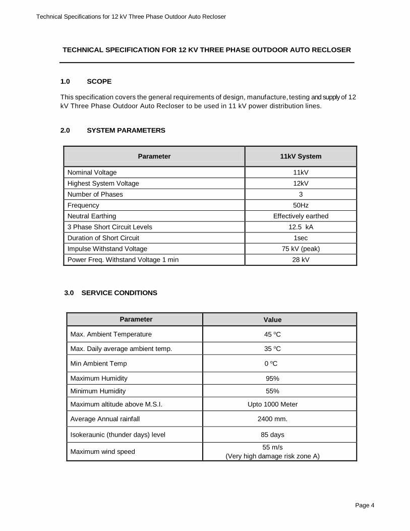
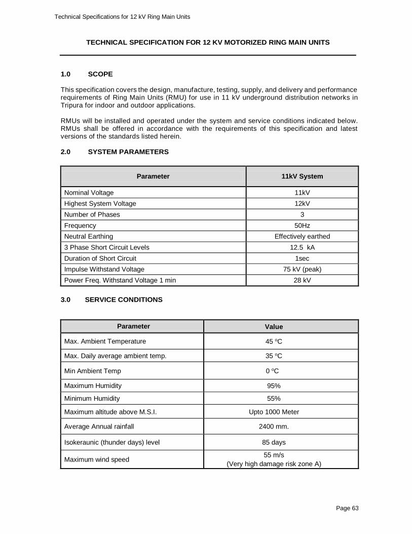
1.0 SCOPE
This specification covers the general requirements of design, manufacture, testing and supply of 12
kV Three Phase Outdoor Auto Recloser to be used in 11 kV power distribution lines.
2.0 SYSTEM PARAMETERS
Parameter 11kV System
Nominal Voltage 11kV
Highest System Voltage 12kV
Number of Phases 3
Frequency 50Hz
Neutral Earthing Effectively earthed
3 Phase Short Circuit Levels 12.5 kA
Duration of Short Circuit 1sec
Impulse Withstand Voltage 75 kV (peak)
Power Freq. Withstand Voltage 1 min 28 kV
3.0 SERVICE CONDITIONS
Parameter Value
Max. Ambient Temperature 45 oC
Max. Daily average ambient temp. 35 oC
Min Ambient Temp 0 oC
Maximum Humidity 95%
Minimum Humidity 55%
Maximum altitude above M.S.I. Upto 1000 Meter
Average Annual rainfall 2400 mm.
Isokeraunic (thunder days) level 85 days
Maximum wind speed 55 m/s
(Very high damage risk zone A)
Page 5
Technical Specifications for 12 kV Three Phase Outdoor Auto Recloser
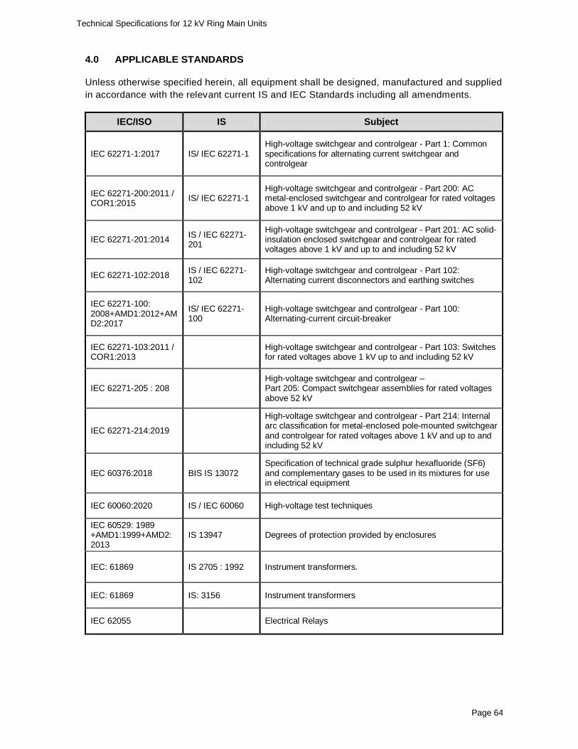
4.0 APPLICABLE STANDARDS
Unless otherwise specified herein, all equipment shall be designed, manufactured and supplied
in accordance with the relevant current IS and IEC Standards including all amendments.
IEC/ISO IS Subject
IEC 62271-111 :2012
High-voltage switchgear and controlgear - Part 111:
Automatic circuit reclosers and fault interrupters for
alternating current - systems up to 38 kV
IEC:62271-100 & 200
IS: 13118 High voltage alternating current circuit breakers general requirement.
IEC: 694 IS: 12729 Common clauses of high voltage switch-gear and control gear standards (for voltage exceeding 1000 V).
IEC: 60060 - 2 IS: 9135 High Voltage testing techniques.
IEC: 427 IS: 13516 Method of synthetic testing of HV .A.C circuit breakers.
IEC: 529 IS: 13947 Degree of protection provided by enclosure.
IEC: 137 IS: 2099 Insulating bushing for A.C. voltages above 1000V
IEC 60815 Selection and dimensioning of high-voltage insulators intended for use in polluted conditions
IEC: 233 IS : 5621 Hollow insulators for use in electrical equipment & testing.
IEC 262217 Polymeric HV insulators for indoor and outdoor use – General definitions, test methods and acceptance criteria.
IEC: 273 IS: 5350 Characteristics of indoor and outdoor post insulators for systems with nominal voltages greater than 1000V.
IEC: 815 IS: 13134 Guide for selection of insulators in respect of polluted conditions.
IEC 60255-149 Measuring relays and protection equipment - Part 149 - Functional requirements for thermal electrical relays
ISO: 1460 BS: 729 IS: 2629 Hot dip galvanizing
IEC: 61869 IS: 2705 Current transformers.
IEC: 61869 IS: 3156 Potential transformers
IEC 60870-5- 101 & 104
Telecontrol equipment and systems - Part 5-101 & 104
Page 6
Technical Specifications for 12 kV Three Phase Outdoor Auto Recloser
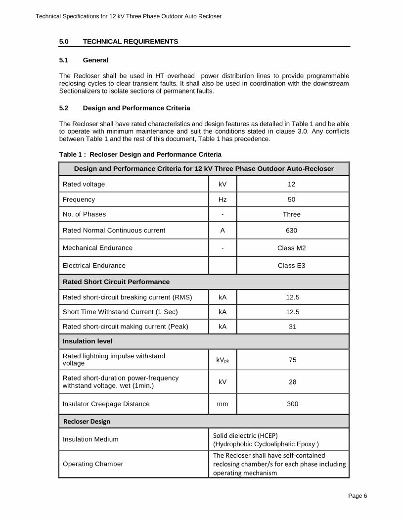
5.0 TECHNICAL REQUIREMENTS
5.1 General
The Recloser shall be used in HT overhead power distribution lines to provide programmable reclosing cycles to clear transient faults. It shall also be used in coordination with the downstream Sectionalizers to isolate sections of permanent faults.
5.2 Design and Performance Criteria
The Recloser shall have rated characteristics and design features as detailed in Table 1 and be able to operate with minimum maintenance and suit the conditions stated in clause 3.0. Any conflicts between Table 1 and the rest of this document, Table 1 has precedence.
Table 1 : Recloser Design and Performance Criteria
Design and Performance Criteria for 12 kV Three Phase Outdoor Auto-Recloser
Rated voltage kV 12
Frequency Hz 50
No. of Phases - Three
Rated Normal Continuous current A 630
Mechanical Endurance - Class M2
Electrical Endurance Class E3
Rated Short Circuit Performance
Rated short-circuit breaking current (RMS) kA 12.5
Insulation Medium Solid dielectric (HCEP) (Hydrophobic Cycloaliphatic Epoxy )
Operating Chamber
The Recloser shall have self-contained reclosing chamber/s for each phase including operating mechanism
Page 7
Technical Specifications for 12 kV Three Phase Outdoor Auto Recloser
Design and Performance Criteria for 12 kV Three Phase Outdoor Auto-Recloser
Interruption Medium Vacuum only.
Operating Mechanism
All three poles shall be simultaneously operated through magnetic actuator mechanism.
Instrument Transformers / Sensors
Current Transformer / Sensor CT sets for each phase to measure phase currents and enable protection schemes.
Voltage Transformer / Sensor
VT / Voltage sensor sets for each phase to measure voltage, enable protection schemes including over / under voltage settings.
Accuracy of measurements Current: ±1% Voltage : ±1%
Opening/ Closing / Locking and Tripping
Tripping Tripping shall be initiated as per protection schemes specified below.
Automatic Switching Schemes
At least four O-CO-CO-CO switching cycles with individually selectable dead times as per IEC 62271.
Manual Locking / Unlocking
Manual locking / unlocking facility by means of a liver mechanism operated using operating rod from ground level. In lock position all operations shall be disabled and Recloser shall be in open position. Lock and unlock positions shall be clearly visible from ground.
Protection Schemes
Frequency Protection
The over and under frequency upto 5 Hz
above / below the system frequency in steps of 0.1 Hz shall be provided. Auto-close
function shall be provided to close upon
returning to normal frequency from tripping due to over/ under frequency.
Voltage Protection
Over / Under voltage trip settings in steps of
1% of nominal system voltage shall be provided for 100% - 150% (overvoltage) and
50% - 100% (under voltage).
Overcurrent and Earth Fault Operation Characteristics
Instantaneous, Standard inverse, Very inverse, Extreme inverse as per IEC60255.
Over Current Setting Range 25% - 150 % of the rated current with
minimum resolution of 1A.
Page 8
Technical Specifications for 12 kV Three Phase Outdoor Auto Recloser
Design and Performance Criteria for 12 kV Three Phase Outdoor Auto-Recloser
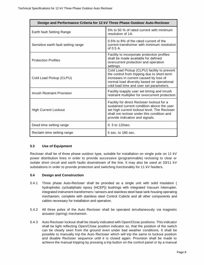
Earth fault Setting Range 5% to 50 % of rated current with minimum resolution of 1A.
Sensitive earth fault setting range 0.5% to 8% of the rated current of the current transformer with minimum resolution of 0.5 A.
Protection Profiles
Facility to incorporate protection profiles shall be made available for defined overcurrent protection and operation settings.
Cold Load Pickup (CLPU)
Cold Load Pickup (CLPU) facility to prevent the control from tripping due to short-term increases in current caused by loss of normal load diversity based on operational cold load time and user set parameters.
Inrush Restraint Provision Facility toapply user set timing and inrush restraint multiplier for overcurrent protection.
High Current Lockout
Facility for direct Recloser lockout for a sustained current condition above the user set high current lockout level. The Recloser shall not reclose under this condition and provide indication and signals.
Dead time setting range 0. 5 to 120sec.
Reclaim time setting range 5 sec. to 180 sec.
5.3 Use of Equipment Recloser shall be of three phase outdoor type, suitable for installation on single pole on 11 kV
power distribution lines in order to provide successive (programmable) reclosing to clear or
isolate short circuit and earth faults downstream of the line. It may also be used at 33/11 kV
substations in order to provide protection and switching functionality for 11 kV feeders.
5.4 Design and Construction 5.4.1 Three phase Auto-Recloser shall be provided as a single unit with solid insulation (
hydrophobic cycloaliphatic epoxy (HCEP)) bushings with integrated Vacuum Interrupter,
integrated instrument transformers / sensors and stainless steel base tank housing operating
mechanism, complete with stainless steel Control Cubicle and all other components and
cables necessary for installation and operation.
5.4.2 All three poles of the Auto Recloser shall be operated simultaneously via magnetic
actuator (spring) mechanism.
5.4.3 Auto Recloser lockout shall be clearly indicated with Open/Close positions. This indicator
shall be light reflecting Open/Close position indicator so, that the position of the switch
can be clearly seen from the ground even under bad weather conditions. It shall be
possible to manually trip the Auto Recloser which will trip the same to lockout position
and disable Recloser sequence until it is closed again. Provision shall be made to
achieve the manual tripping by pressing a trip button on the control panel or by a manual
Page 9
Technical Specifications for 12 kV Three Phase Outdoor Auto Recloser
control lever or by a remote operator via modem interface.
5.4.4 Mechanical and electrical Endurance of Auto Recloser shall be 10,000 or more in/out
operations. Auto Recloser operations shall be recorded by a mechanical or electrical
counter which can be accessed in the field via control panel display unit and field
computer using the associated computer software package.
5.4.5 All non-metal parts including insulating materials of cables shall be able to withstand
effects due to ultra violet radiation.
5.4.6 The Recloser shall have a separate button on the control panel to lock and unlock
reclosing action manually in case of live line maintenance work is done at the
downstream of the power line.
5.4.7 The Auto Recloser shall be provided with suitable Pole Mounting Steel Frame with Lifting
Tackle, Surge Arrester Mounting Brackets on the both source and load side.
5.4.8 Earthing terminal suitable to accommodate two Nos. 5mm diameter to 15 mm diameter
earthing conductors shall also be provided for bonding the Auto Recloser base tank, mounting frame and the surge arrester earth terminal to the local earthing electrodes .
5.4.9 Tripping shall be initiated by overcurrent, earth fault and instantaneous relays. The type
of overcurrent, earth fault and sensitive earth relays and their operating current/time
setting ranges shall conform to the protection schemes specified in Table 1. In addition
frequency and voltage protections shall be provided as specified.
5.4.10 The automatic switching schemes shall comply with requirements specified in Table 1.
5.5 Vacuum Interrupters
The vacuum interrupters shall be of a reputed make with proven track record. The
vacuum interrupters shall be of proven and tested design that provide high fault-
interrupting capability, fast low energy arc interruption, minimum and even contact wear
and minimum heat generation.
Number of full load interruptions, full fault interruptions and number of half fault
interruption that could be performed by the interrupter during its life span shall be
furnished. Remaining percentage contact wear shall be recorded in the Auto Recloser
and shall indicate in the control panel.
5.6 Operating Mechanism
The Recloser operating mechanism shall be 3-phase gang operated. It shall consist of
a bi-stable magnetic actuator capable of fast opening and closing operations with no
recharging delay. Bi-stable refers to that no operating power is required to hold the unit
open or closed. Close and trip capacitors shall be used to store the necessary energy
for operating the magnetic actuator. The magnetic actuators shall be of reputed make with
proven track record.
5.7 Insulation
The Recloser bushings shall use Hydrophobic Cycloaliphatic Epoxy (HCEP) as the
dielectric insulating medium and be highly resistant to ozone, oxygen, moisture,
Page 10
Technical Specifications for 12 kV Three Phase Outdoor Auto Recloser
contamination and ultraviolet light. No coatings or UV protective covers are acceptable.It
shall provide high resistance to damage. The hydrophobic cycloaliphatic epoxy shall
provide complete encapsulation of the internal vacuum interrupter. The encapsulation
shall also be completely bonded to the source and load side bushing terminals. The
Recloser bushings shall be designed utilizing alternating minor and major skirts to
increase creepage distance.
5.8 Control and Protection
5.8.1 All protection settings and the reclosing pattern shall be configurable by both control
panel and a computer which is connected remotely or locally. A minimum of four (04)
tripping operations to lockout shall be provided and the number and sequence of operations to lockout shall be adjustable in the field.
5.8.2 The applicable over current tripping shall be of the instantaneous, standard inverse, very
inverse and extreme inverse types as per IEC 60255-149 and the tripping current/time
delay setting range shall be as stipulated in Clause 5.2. Inrush restraint, CLPU and High Current Lockout facilities shall be also provided. The tripping current/time delay setting
range for earth fault and sensitive earth fault tripping shall be as stipulated in Table 1.
5.8.3 If the fault is cleared by any one of the Auto Recloser operations and the Auto Recloser
remains closed, it shall reset itself for another complete sequence of operations. The reset time shall be adjustable from 5-180sec.
5.8.4 The successful bidder shall be responsible to set auto-recloser protection curve settings
in field so as to coordinate with other upstream breakers and fuses to ensure that only the faulty section downstream of the Aauto- Recloser will be isolated in the event of a
permanent fault. In case Automatic Sectionalizers are used downstream of the Recloser
successful bidder must ensure that Automatic Sectionalizers are coordinated with Reclosing cycles are coordinated with the to isolate only the faulty section of the line.
The successful bidder shall provide proposed scheme for coordination of the protective
and sectionalizing devices for respective for approval of the Project Manager prior to
implementation in field. 5.9 Control Cabinet
5.9.1 The Recloser shall be supplied with Control Cabinet with an integrated microprocessor based control and protection system incorporating all control and protection features
specified in this specification.
5.9.2 Control cabinet shall have a display panel with backlit LCD and keypad to provide
navigation and local control. Navigation keys shall be able to disable with password
protection. Navigation menus should be presented in easily understandable text for the
operators. Basic configurations can be carried out using navigation keys and LCD display. It shall also be possible to read instantaneous current, voltage, power and
system logs values through LCD display.
5.9.3 The control system shall have facilities for data logging of network parameters such as
current, voltage, active power, reactive power, energy, Instantaneous Measurements in the events of operation of Auto Recloser, change of network configuration, power interruptions and restorations etc
5.9.4 The control cabinet shall be provided with auxiliary power supply, battery system and
battery charging system as specified in clause 5.11 (Auxiliary Supply)
5.9.5 The enclosure of the control cabinet shall have IP 54 or higher rating. Cabinet shall be
Page 11
Technical Specifications for 12 kV Three Phase Outdoor Auto Recloser
designed for the specified service conditions, adequately ventilated and fitted with
substantial door securing devices capable of ensuring entry by only authorized personnel. Cabinet shall be adequately sealed and dust protected and shall be internally
treated to prevent moisture condensation.
5.9.6 The cabinet shall be designed for the service conditions specified, adequately ventilated
and fitted with substantial door securing devices capable of being padlocked by a
padlock with a shank of 8mm with the door in the closed position.
5.9.7 The equipment housed in the control cabinet shall withstand the heating effect of direct
solar radiation without causing failure and/or mal-operation.
5.9.8 The cabinet shall make provision for bottom entry of at least two additional cables. The
cabinet shall be pre-punched with at least one 21mm and one 32mm hole. The holes shall
be suitably blanked off. The cabinet shall be fitted with an external M12 earthing stud, with a nut, lock nut, and a serrated washer.
5.9.9 The control cabinet shall be mounted below the Recloser and shall be connected to the
Recloser switchgear by a minimum seven meter long multi-core control cable. The multi-core cable shall be ultra violet stabilized and adequately screened against electrostatic
and electromagnetic interference, which can cause malfunctioning of the protection or
control equipment. This cable shall connect into both the Recloser and the control
cabinet by means of plug and socket arrangements. Entry of the control cable into the Control Cubicle shall be from the bottom.
5.10 Software
5.10.1 It shall be possible to download data stored in control unit and configure the Recloser
settings using a portable computer locally or remotely. Interfacing should be via USB port.
5.10.2 Computer software compatible with Windows 7 or later to upload and download
protection settings, to provide history information (event data logs, load profile, etc) to
display breaker contact erosion data etc., shall be supplied. The software shall be
capable of connecting to control and protection system locally or remotely via
communication system. The protocol for data transfer shall be in accordance with 5.12.
5.10.3 The software should have the facility to install on any computer without a separate
license and record the event history to get the information of the access user. The
software should have separate authority levels for ;
Programming, Operating and Monitoring
Operating and Monitoring
Monitoring
5.10.4 The offered software should be backward-compatible with the previous version. A copy
of the manual of the software shall accompany the bid. Required one set of interface
cables shall be provided with every ten units or part thereof.
5.10.5 The downloaded data shall be stored in a suitable fool proof database. This data shall
be able to be extracted as a delimited text format or MS Excel format.
5.10.6 Software shall be valid or provided with necessary keys and upgrades for at least the
full life span of the equipment. The manufacturer/ supplier shall provide necessary
support throughout this period. The software should facilitate remote data downloading
individually from each equipment.
Page 12
Technical Specifications for 12 kV Three Phase Outdoor Auto Recloser
5.11 Auxiliary Supply
5.11.1 Auxiliary supply for the operating mechanism and control cabinet of the Recloser shall
normally be from an internal sealed battery fitted with a charging system.
5.11.2 The battery system shall be capable of initiating correct operation of the Recloser including controls, protections and communications for not less than 3 days (at 6 operations per day)
after loss of ac auxiliary supply.
5.11.3 The battery system shall incorporate a battery test facility. The following features shall be
regarded as typical of the 'test' / 'monitoring' facilities required.
(b) An alarm signal in the event of loss of the battery system or poor battery condition.
5.11.4 The charging system shall operate from a HT Voltage Transformer, incorporated into the installation. The Voltage Transformer for auxiliary supply shall be designed, manufactured
and tested in accordance with IEC 61869-3. It shall be provided with adequate capacity for
provision of auxiliary supply for operating mechanism, control cabinet including RTU and
communication equipment to be incorporated in the control cabinet in future.
It shall be suitable for mounting on the Recloser pole and supplied complete with a pole
mounting bracket. The auxiliary supply VT shall have a primary winding suitable for connecting to the 11 KV line and a secondary output voltage of 240V.
5.11.5 A 2A HRC fuse or a circuit breaker shall be provided in the secondary terminal box of the VT
to facilitate the isolation of the secondary wiring in the event of a fault.
5.11.6 A name plate marked with the following information shall be provided on the auxiliary VT:
Manufacturer’s name, serial number, rated impulse withstand level, primary and secondary
voltages, rated current.
5.12 Remote Control / SCADA
5.12.1 Auto Recloser shall have the facility to monitor and control remotely from Control Station
(future application). Provision for incorporating Remote Terminal Unit (RTU) with the
Controller shall be provided for this future application.
5.12.2 The incorporated Remote Terminal Unit (RTU) shall be compatible with GSM/ GPRS/
3G/4G or latest communication module that allows the Auto Recloser to communicate
over cellular network with remote server / PC and software supplied as per clause 5.10.
The communication protocol shall conform to DNP3.0, IEC 60870-5-101& 104 latest
versions. Any additional software for RTU / Communications shall be provided.
5.12.3 Following communication ports shall be provided for SCADA and local configuration.
RS232 (SCADA)
Ethernet RJ45 (SCADA)
USB (Local configuration)
5.12.4 The RTU shall communicate and shall allow for the processing of all analogue and digital
signals including inputs, outputs, measurements and alarms in order to monitor and
control the Auto Recloser remotely. The power supply for RTU shall be provided from
internal battery.
Page 13
Technical Specifications for 12 kV Three Phase Outdoor Auto Recloser
5.12.5 Voltage detection on both sides of the opened switch shall be possible from the control
centre. The measurement of line parameters (line voltages: on both side of one phase,
phase currents) and maintenance information (such as retrieval of ‘Number of switching
operations performed’) shall be possible from the control center. Periodical, continuous
and on – request remote data acquisition modes shall be available.
5.12.6 The RTU shall be firmware upgradable.
5.12.7 The supply of RTU / communication module with the Recloser is optional. The BOQ may
however include supply of these equipment for limited number of Reclosers for testing
of remote monitoring and control. In such case the successful bidder is required provide
complete system solution including equipment and software for both device and server
ends to implement remote monitoring and control of the Recloser. 5.13 Rating Plate Markings
The ratings and data of the Auto Recloser shall be provided in the rating plate which
shall be weather and corrosion proof.
Rating plate shall be provided at the lower part of the base tank and shall consist
following information.
i) Manufacturer's name and trademark
ii) Type designation and serial number
iii) Standard adopted with the year and the edition
iv) Rated voltage, Basic Impulse and Power Frequency Withstand Levels
v) Rated continuous current and short time current with duration
vi) Year of manufacture
vii) Purchasers Name : TSECL
6.0 Quality Assurance
The manufacturer shall have an established quality assurance system in the process
of design, manufacture and testing of equipment. The bidder shall furnish related quality
system details and Quality Assurance Certifications such as ISO certifications, along
with the offer.
7.0 Manufacturing Experience
The manufacturer of Auto Recloser shall have minimum of 10 years of experience in
manufacturing similar products. The product offered shall have been in service in
electricity utilities over past 5 years.
The bidder shall furnish list of purchasers with year and quantity of the product offered
along with the bid to prove his manufacturing experience.
8.0 Spares
8.1 Mandatory Spares
The following mandatory spare parts shall be provided;
01 Nos Control Unit for every 10 Nos. of Reclosers or part thereof.
01 Nos auxiliary supply VT for every 10 Nos. of Reclosers or part thereof.
Page 14
Technical Specifications for 12 kV Three Phase Outdoor Auto Recloser
8.2 Manufacturer Recommended Spare Parts
A list of manufacturers recommended spare parts with current prices for 5 year trouble
free operation and out maintenance of the Recloser shall be submitted along with the
bid.
In case special testing equipment and tools are required for testing and maintenance of the Recloser, such testing equipment and tools shall be supplied along with the Reclosers.
9.0 Training
The bidder shall provide training on the use of offered Recloser to nominated TSECL staffs through the Manufacturer. Training shall cover installation, operation and maintenance of the Recloser and its Control and Protection system. This should also include setting up parameters for protection and control.
10.0 Warranty
The Bidder shall warrant that all Goods supplied shall have no defect arising from
design, materials or workmanship or from any act or omission of the supplier, that may
develop under normal use of the supplied goods in the conditions as specified. This Warranty shall remain valid for twelve (12) months after the completion of the final
delivery.
In addition, three (3) years comprehensive warranty for electronic devices and cards in
the control panel shall be provided.
11.0 Technical Literature and Drawings
The successful bidder shall provide catalogues with all relevant drawings, technical
literature, calculations, operating manuals for equipment and software etc. required for
installation, operation, and maintenance of the equipment. The details shall cover the
main plant and all associated ancillary equipment and software as supplied under the
offer.
12.0 INSPECTION AND TESTING
The Auto-Recloser shall be subjected to routine and type tests in accordance with the
standards listed in this specification. The tests shall include but not limited to the following;
12.1 Type Tests
The following Certificates of type tests as per relevant IEC / IS standards shall be provided.
(a) Dielectric tests
(b) Making and breaking tests
(c) Short time withstand and peak withstand current tests
(d) Measurements of resistance of the main circuit
(e) Temperature raise tests
(f) Dimensional tests
(g) Surge current
(h) Temperature rise test
(i) Time current tests
Page 15
Technical Specifications for 12 kV Three Phase Outdoor Auto Recloser
(j) Mechanical operation tests
(k) Control electronic elements surge withstand capability and EMI tests
(l) Accelerated weathering test in accordance with IEC 62217 (on bushing
Insulators).
Type test reports should be issued during period not exceeding 5 years from the bid
opening date. In case the type test reports are of the test conducted earlier than 5 (five)
years prior to the date of bid opening, the bidder shall repeat these test(s) at no extra
cost.
Type tests reports shall be from reputed independent CPRI / NABL accredited testing
laboratories in India or reputed international test laboratories accredited to ISO/IEC
17025:2005 for carrying out specified type tests. Proof of accreditation by a national/
international authority shall be forwarded with the offer. The test laboratories should be
acceptable to TSECL.
12.2 Routine Tests
The following Routine Tests in accordance with relevant IEC standards shall be carried
out on all units and test report shall be furnished for the observation of the Engineer
appointed by the purchaser at the time of inspection.
(a) Dielectric test on the main circuit
(b) Measurement of the resistance of the main circuit
(c) Tightness test
(d) Reclosing and overcurrent trip calibration
(e) Partial discharge test
(f) Mechanical operations tests
12.3 Inspection
The Successful bidder shall make necessary arrangements for inspection by TSECL
nominated representative and also to carry out in his presence necessary Acceptance
tests on the Recloser.
The successful bidder shall give reasonable notice of when the acceptance/sample /routine
tests are to be carried out. TSECL reserves the right to appoint representatives to witness
the tests as well as conduct design reviews, and periodic inspection of the Recloser during
manufacture.
12.4 Acceptance Tests The following Acceptance/Sample tests as per IEC 62271-111 or equivalent BIS standard shall be witnessed by the TSECL nominated representative;
(a) Control unit calibration checks, wiring, operating and functional tests
(b) Wiring and operating checks
(c) Dielectric withstand tests
(d) Mechanical operation checks
(e) Leakage check
(f) Temperature rise test
(g) Duty Cycle Tests
(h) Verification of remote operation with the software
(i) Dimensional tests
Page 16
Technical Specifications for 12 kV Three Phase Outdoor Auto Recloser
13.0 INFORMATION TO BE FURNISHED BY THE BIDDER
The following shall be furnished with the offer.
(a) Catalogues describing the equipment - Recloser, Control Cabinet, Software and
Auxiliary supply VT.
(b) Literature describing the operational feature of the equipment.
(c) Constructional features, materials used for components and relevant technical
literature.
(d) The following drawings;
i) Overall dimensional drawing of the Auto Recloser including general
arrangement.
ii) Electrical clearance requirements of installation
iii) Insulator assembly and shed profile
iv) Dimensional drawing of mounting arrangement.
v) Name plate to scale, incorporating the particulars called for.
(e) Manufacturing experience in accordance with clause 7.0
(f) List of Manufacturer Recommended Spare Parts with current prices as per
clause 8.2.
(g) Copies of type test reports as per clause 12.1
(h) Quality Assurance Certification as per clause 6.0.
(i) Completed schedule of guaranteed technical particulars and schedule of
deviations.
Failure to furnish the above information may result in the offer being rejected.
Page 17
Technical Specifications for 12 kV Three Phase Outdoor Auto Recloser
IEC: 529 IS: 13947 Degree of protection provided by enclosure.
IEC: 137 IS: 2099 Insulating bushing for A.C. voltages above 1000V
IEC 60815 Selection and dimensioning of high-voltage insulators intended for use in polluted conditions
IEC: 233 IS : 5621 Hollow insulators for use in electrical equipment & testing.
IEC 262217 Polymeric HV insulators for indoor and outdoor use – General definitions, test methods and acceptance criteria.
IEC: 273 IS: 5350 Characteristics of indoor and outdoor post insulators for systems with nominal voltages greater than 1000V.
IEC: 815 IS: 13134 Guide for selection of insulators in respect of polluted conditions.
IEC 60255-149 Measuring relays and protection equipment - Part 149 - Functional requirements for thermal electrical relays
ISO: 1460 BS: 729 IS: 2629 Hot dip galvanizing
IEC: 61869 IS: 2705 Current transformers.
IEC: 61869 IS: 3156 Potential transformers
Page 25
Technical Specifications for 12 kV Three Phase Outdoor Sectionalizer / Load Break Switch
IEC/ISO IS Title
IEC 60870-5- 101 & 104
Telecontrol equipment and systems - Part 5-101 & 104
5.0 TECHNICAL REQUIREMENTS
5.1 Functionality
The Sectionalizer / LBS will be used in the downstream of the Automatic Circuit Recloser to protect the medium voltage overhead lines by isolating (sectionalizing) the faulty sections / branches (spurs) of the line. The sectionalizing functionality shall facilitate operation in radial lines as specified below; The Sectionalizer / LBS will be used in radial lines where the power flows in one direction (forward direction). It will receive power from upstream side and coordinate with the upstream Recloser to isolate faults. The Sectionalizer will be in normally closed position and will open during the dead time of the specified count of the reclosing sequence upon detection of downstream overcurrent or earth fault. In addition to above, the Sectionalizing facility may be used for open ring and ring closing applications in future for interconnecting two feeders in open loop configuration to improve reliability. Therefore the Sectionalizer shall preferably facilitate these future applications with provision of appropriate modes of operation for respective applications. It addition Sectionalizer / LBS shall also be used as a load break switch (LBS) for manual switching operations of the power lines. In load breaking mode the automatic sectionalizing functionality should be disabled. 5.2 Design and Performance Criteria
The Sectionalizer / LBS shall have rated characteristics and design features as detailed in Table 1 and be able to operate with minimum maintenance and suit the conditions stated in clause 3.0. Any conflicts between Table 1 and the rest of this document, Table 1 has precedence. Table 1 : Sectionalizer / LBS Design and Performance Criteria
Design and Performance Criteria for 12 kV Three Phase Outdoor Sectionalizer / LBS
Rated voltage kV 12
Frequency Hz 50
No. of Phases - Three
Rated Normal Continuous current A 630
Mechanical Endurance - Class M2
Electrical Endurance - Class E3
Rated Short Circuit Performance
Rated breaking current (RMS) A 630
Short Time Withstand Current (1 Sec) kA 12.5
Page 26
Technical Specifications for 12 kV Three Phase Outdoor Sectionalizer / Load Break Switch
Design and Performance Criteria for 12 kV Three Phase Outdoor Sectionalizer / LBS
Insulation Medium Solid dielectric (HCEP) (Hydrophobic Cycloaliphatic Epoxy )
Operating Chamber
The Sectionalizer / LBS shall have self-contained switching chamber/s for each phase including operating mechanism
Interruption Medium Vacuum only.
Operating Mechanism
All three poles shall be simultaneously operated through magnetic actuator mechanism.
Instrument Transformers / Sensors
Current Transformer / Sensor
CT sets for each phase to measure phase currents and detection of phase / earth faults.
Voltage Transformer / Sensor
VT / Voltage sensor sets for each phase on both sides to measure voltage and enable fault detection.
Accuracy of measurements Current: ±1% Voltage : ±1%
Opening/ Closing / Locking and Tripping
Sectionalizing
In sectionalizing mode Sectionalizer / LBS shall trip during the dead time of the specified count of reclosing sequence upon detection of downstream overcurrent or earth fault.
Sectionalizer / LBS shall be able to be closed onto a fault during fault restoration operation via local or remote control.
Load Breaking
In load breaking mode Sectionalizer / LBS shall be able to open or close via local or remote control. Automatic sectionalizing
Page 27
Technical Specifications for 12 kV Three Phase Outdoor Sectionalizer / Load Break Switch
Design and Performance Criteria for 12 kV Three Phase Outdoor Sectionalizer / LBS
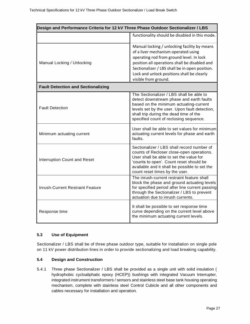
functionality should be disabled in this mode.
Manual Locking / Unlocking
Manual locking / unlocking facility by means of a liver mechanism operated using operating rod from ground level. In lock position all operations shall be disabled and Sectionalizer / LBS shall be in open position. Lock and unlock positions shall be clearly visible from ground.
Fault Detection and Sectionalizing
Fault Detection
The Sectionalizer / LBS shall be able to detect downstream phase and earth faults
based on the minimum actuating-current
levels set by the user. Upon fault detection,
shall trip during the dead time of the specified count of reclosing sequence.
Minimum actuating current
User shall be able to set values for minimum actuating current levels for phase and earth
faults.
Interruption Count and Reset
Sectionalizer / LBS shall record number of counts of Recloser close-open operations.
User shall be able to set the value for ‘counts to open’. Count reset should be
available and it shall be possible to set the
count reset times by the user.
Inrush-Current Restraint Feature
The inrush-current restraint feature shall
block the phase and ground actuating levels for specified period after line current passing
through the Sectionalizer / LBS to prevent
actuation due to inrush currents.
Response time
It shall be possible to set response time curve depending on the current level above
the minimum actuating current levels.
5.3 Use of Equipment Sectionalizer / LBS shall be of three phase outdoor type, suitable for installation on single pole
on 11 kV power distribution lines in order to provide sectionalizing and load breaking capability.
5.4 Design and Construction 5.4.1 Three phase Sectionalizer / LBS shall be provided as a single unit with solid insulation (
hydrophobic cycloaliphatic epoxy (HCEP)) bushings with integrated Vacuum Interrupter,
integrated instrument transformers / sensors and stainless steel base tank housing operating
mechanism, complete with stainless steel Control Cubicle and all other components and
cables necessary for installation and operation.
Page 28
Technical Specifications for 12 kV Three Phase Outdoor Sectionalizer / Load Break Switch
5.4.2 All three poles of the Sectionalizer / LBS shall be operated simultaneously via magnetic
actuator (spring) mechanism.
5.4.3 Sectionalizer / LBS lockout shall be clearly indicated with Open/Close positions. This
indicator shall be light reflecting Open/Close position indicator so, that the position of the
switch can be clearly seen from the ground even under bad weather conditions. It shall
be possible to manually open the Sectionalizer / LBS which will trip the same to lockout
position and disable Sectionalizing sequence until it is closed again. Provision shall be
made to achieve the manual tripping by pressing a trip button on the control panel or by
a manual control lever or by a remote operator via modem interface.
5.4.4 Mechanical and electrical Endurance of Sectionalizer / LBS shall be 10,000 or more
in/out operations. Sectionalizer / LBS operations shall be recorded by a mechanical or
electrical counter which can be accessed in the field via control panel display unit and
field computer using the associated computer software package.
5.4.5 All non-metal parts including insulating materials of cables shall be able to withstand
effects due to ultra violet radiation.
5.4.6 The Sectionalizer / LBS shall be provided with suitable Pole Mounting Steel Frame with
Lifting Tackle, Surge Arrester Mounting Brackets on the both source and load side.
5.4.7 Earthing terminal suitable to accommodate two Nos. 5mm diameter to 15 mm diameter earthing conductors shall also be provided for bonding the Sectionalizer / LBS base tank,
mounting frame and the surge arrester earth terminal to the local earthing electrodes .
5.5 Vacuum Interrupters
The vacuum interrupters shall be of a reputed make with proven track record. The
vacuum interrupters shall be of proven and tested design that provide high fault-
interrupting capability, fast low energy arc interruption, minimum and even contact wear
and minimum heat generation.
Number of full load interruptions, rated fault closing operations that could be performed
by the interrupter during its life span shall be furnished. Remaining percentage contact
wear shall be recorded in the Sectionalizer / LBS and shall indicate in the control panel.
5.6 Operating Mechanism
The Sectionalizer / LBS operating mechanism shall be 3-phase gang operated. It shall
consist of a bi-stable magnetic actuator capable of fast opening and closing operations
with no recharging delay. Bi-stable refers to that no operating power is required to hold
the unit open or closed. Close and trip capacitors shall be used to store the necessary
energy for operating the magnetic actuator. The magnetic actuators shall be of reputed
make with proven track record.
5.7 Insulation
The Sectionalizer / LBS bushings shall use Hydrophobic Cycloaliphatic Epoxy (HCEP)
as the dielectric insulating medium and be highly resistant to ozone, oxygen, moisture,
contamination and ultraviolet light. No coatings or UV protective covers are acceptable.
It shall provide high resistance to damage. The hydrophobic cycloaliphatic epoxy shall
provide complete encapsulation of the internal vacuum interrupter. The encapsulation
Page 29
Technical Specifications for 12 kV Three Phase Outdoor Sectionalizer / Load Break Switch
shall also be completely bonded to the source and load side bushing terminals. The
Sectionalizer / LBS bushings shall be designed utilizing alternating minor and major
skirts to increase creepage distance.
5.8 Fault Detection and Sectionalizing
5.8.1 The Sectionalizer / LBS shall be able to detect downstream phase and earth faults based
on the minimum actuating-current levels set by the user. Upon fault detection, shall trip during the dead time of the specified count of reclosing sequence
5.8.2 User shall be able to set values for minimum actuating current levels for phase and earth
faults.
5.8.3 Sectionalizer / LBS shall record number of counts of Recloser close-open operations.
User shall be able to set the value for ‘counts to open’. Count reset should be available
and it shall be possible to set the count reset times by the user.
5.8.4 The inrush-current restraint feature shall be available to block the phase and ground
actuating levels for specified period after line current passing through the Sectionalizer
/ LBS to prevent actuation due to inrush currents.
5.8.5 It shall be possible to set response time curve depending on the current level above the
minimum actuating current levels.
5.8.6 The successful bidder shall be responsible to establish settings for Sectionalizer / LBS
in order to ensure proper coordination with upstream Recloser and other sectionalizing
devices installed in the line. The successful bidder shall provide proposed scheme for
reclosing and sectionalizing of respective feeders for approval of the Project Manager prior to implementation in field.
5.9 Control Cabinet
5.9.1 The Sectionalizer / LBS shall be supplied with Control Cabinet with an integrated microprocessor based control system incorporating all control and fault detection
features specified in this specification.
5.9.2 Control cabinet shall have a display panel with backlit LCD and keypad to provide
navigation and local control. Navigation keys shall be able to disable with password
protection. Navigation menus should be presented in easily understandable text for the operators. Basic configurations can be carried out using navigation keys and LCD
display. It shall also be possible to read instantaneous current, voltage, power and
system logs values through LCD display.
5.9.3 The control cabinet shall be provided with auxiliary power supply, battery system and
battery charging system as specified in clause 5.11 (Auxiliary Supply)
5.9.4 The enclosure of the control cabinet shall have IP 54 or higher rating. Cabinet shall be designed for the specified service conditions, adequately ventilated and fitted with
substantial door securing devices capable of ensuring entry by only authorized
personnel. Cabinet shall be adequately sealed and dust protected and shall be internally treated to prevent moisture condensation.
5.9.5 The cabinet shall be designed for the service conditions specified, adequately ventilated
and fitted with substantial door securing devices capable of being padlocked by a
Page 30
Technical Specifications for 12 kV Three Phase Outdoor Sectionalizer / Load Break Switch
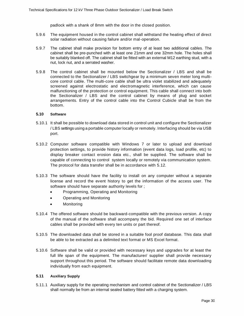
padlock with a shank of 8mm with the door in the closed position.
5.9.6 The equipment housed in the control cabinet shall withstand the heating effect of direct
solar radiation without causing failure and/or mal-operation.
5.9.7 The cabinet shall make provision for bottom entry of at least two additional cables. The
cabinet shall be pre-punched with at least one 21mm and one 32mm hole. The holes shall
be suitably blanked off. The cabinet shall be fitted with an external M12 earthing stud, with a nut, lock nut, and a serrated washer.
5.9.8 The control cabinet shall be mounted below the Sectionalizer / LBS and shall be
connected to the Sectionalizer / LBS switchgear by a minimum seven meter long multi-core control cable. The multi-core cable shall be ultra violet stabilized and adequately
screened against electrostatic and electromagnetic interference, which can cause
malfunctioning of the protection or control equipment. This cable shall connect into both the Sectionalizer / LBS and the control cabinet by means of plug and socket
arrangements. Entry of the control cable into the Control Cubicle shall be from the
bottom.
5.10 Software
5.10.1 It shall be possible to download data stored in control unit and configure the Sectionalizer
/ LBS settings using a portable computer locally or remotely. Interfacing should be via USB
port.
5.10.2 Computer software compatible with Windows 7 or later to upload and download
protection settings, to provide history information (event data logs, load profile, etc) to
display breaker contact erosion data etc., shall be supplied. The software shall be
capable of connecting to control system locally or remotely via communication system.
The protocol for data transfer shall be in accordance with 5.12.
5.10.3 The software should have the facility to install on any computer without a separate
license and record the event history to get the information of the access user. The
software should have separate authority levels for ;
Programming, Operating and Monitoring
Operating and Monitoring
Monitoring
5.10.4 The offered software should be backward-compatible with the previous version. A copy
of the manual of the software shall accompany the bid. Required one set of interface
cables shall be provided with every ten units or part thereof.
5.10.5 The downloaded data shall be stored in a suitable fool proof database. This data shall
be able to be extracted as a delimited text format or MS Excel format.
5.10.6 Software shall be valid or provided with necessary keys and upgrades for at least the
full life span of the equipment. The manufacturer/ supplier shall provide necessary
support throughout this period. The software should facilitate remote data downloading
individually from each equipment.
5.11 Auxiliary Supply
5.11.1 Auxiliary supply for the operating mechanism and control cabinet of the Sectionalizer / LBS
shall normally be from an internal sealed battery fitted with a charging system.
Page 31
Technical Specifications for 12 kV Three Phase Outdoor Sectionalizer / Load Break Switch
5.11.2 The battery system shall be capable of initiating correct operation of the Sectionalizer / LBS including controls and operations for not less than 3 days after loss of ac auxiliary supply.
5.11.3 The battery system shall incorporate a battery test facility. The following features shall be
regarded as typical of the 'test' / 'monitoring' facilities required.
(b) An alarm signal in the event of loss of the battery system or poor battery condition.
5.11.4 The charging system shall operate from a HT Voltage Transformer, incorporated into the
installation. The Voltage Transformer for auxiliary supply shall be designed, manufactured and tested in accordance with IEC 61869-3. It shall be provided with adequate capacity for
provision of auxiliary supply for operating mechanism, control cabinet including RTU and
communication equipment to be incorporated in the control cabinet in future.
It shall be suitable for mounting on the Sectionalizer / LBS pole and supplied complete with
a pole mounting bracket. The auxiliary supply VT shall have a primary winding suitable for
connecting to the 11 KV line and a secondary output voltage of 240V.
5.11.5 A 2A HRC fuse or a circuit breaker shall be provided in the secondary terminal box of the VT
to facilitate the isolation of the secondary wiring in the event of a fault.
5.11.6 A name plate marked with the following information shall be provided on the auxiliary VT:
Manufacturer’s name, serial number, rated impulse withstand level, primary and secondary
voltages, rated current.
5.12 Remote Control / SCADA
5.12.1 Sectionalizer / LBS shall have the facility to monitor and control remotely from Control
Station (future application). Provision for incorporating Remote Terminal Unit (RTU) with
the Controller shall be provided for this future application.
5.12.2 The incorporated Remote Terminal Unit (RTU) shall be compatible with GSM/ GPRS/
3G/4G or latest communication module that allows the Sectionalizer / LBS to
communicate over cellular network with remote server / PC and software supplied as
per clause 5.10. The communication protocol shall conform to DNP3.0, IEC 60870-5-
101& 104 latest versions. Any additional software for RTU / Communications shall be
provided.
5.12.3 Following communication ports shall be provided for SCADA and local configuration.
RS232 (SCADA)
Ethernet RJ45 (SCADA)
USB (Local configuration)
5.12.4 The RTU shall communicate and shall allow for the processing of all analogue and digital
signals including inputs, outputs, measurements and alarms in order to monitor and
control the Sectionalizer / LBS remotely. The power supply for RTU shall be provided
from internal battery.
5.12.5 Voltage detection on both sides of the opened switch shall be possible from the control
centre. The measurement of line parameters (line voltages: on both side of one phase,
phase currents) and maintenance information (such as retrieval of ‘Number of switching
operations performed’) shall be possible from the control center. Periodical, continuous
and on – request remote data acquisition modes shall be available.
Page 32
Technical Specifications for 12 kV Three Phase Outdoor Sectionalizer / Load Break Switch
5.12.6 The RTU shall be firmware upgradable.
5.12.7 The supply of RTU / communication module with the Sectionalizer / LBS is optional. The
BOQ may however include supply of these equipment for limited number of Sectionalizer
/ LBS for testing of remote monitoring and control. In such case the successful bidder is
required provide complete system solution including equipment and software for both
device and server ends to implement remote monitoring and control of the Sectionalizer
/ LBS.
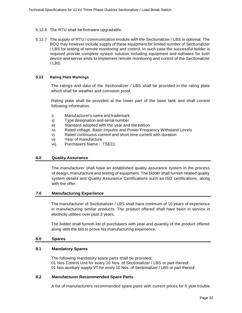
5.13 Rating Plate Markings
The ratings and data of the Sectionalizer / LBS shall be provided in the rating plate
which shall be weather and corrosion proof.
Rating plate shall be provided at the lower part of the base tank and shall consist
following information.
i) Manufacturer's name and trademark
ii) Type designation and serial number
iii) Standard adopted with the year and the edition
iv) Rated voltage, Basic Impulse and Power Frequency Withstand Levels
v) Rated continuous current and short time current with duration vi) Year of manufacture
vii) Purchasers Name : TSECL
6.0 Quality Assurance
The manufacturer shall have an established quality assurance system in the process
of design, manufacture and testing of equipment. The bidder shall furnish related quality
system details and Quality Assurance Certifications such as ISO certifications, along
with the offer.
7.0 Manufacturing Experience
The manufacturer of Sectionalizer / LBS shall have minimum of 10 years of experience
in manufacturing similar products. The product offered shall have been in service in
electricity utilities over past 3 years.
The bidder shall furnish list of purchasers with year and quantity of the product offered
along with the bid to prove his manufacturing experience.
8.0 Spares
8.1 Mandatory Spares
The following mandatory spare parts shall be provided;
01 Nos Control Unit for every 10 Nos. of Sectionalizer / LBS or part thereof.
01 Nos auxiliary supply VT for every 10 Nos. of Sectionalizer / LBS or part thereof.
8.2 Manufacturer Recommended Spare Parts
A list of manufacturers recommended spare parts with current prices for 5 year trouble
Page 33
Technical Specifications for 12 kV Three Phase Outdoor Sectionalizer / Load Break Switch
free operation and out maintenance of the Sectionalizer / LBS shall be submitted along
with the bid.
In case special testing equipment and tools are required for testing and maintenance of the Sectionalizer / LBS, such testing equipment and tools shall be supplied along with the
Sectionalizer / LBS.
9.0 Training
The bidder shall provide training on the use of offered Sectionalizer / LBS to nominated TSECL staffs through the Manufacturer. Training shall cover installation, operation and maintenance of the Sectionalizer / LBS and its control system. This should also include setting up parameters for fault detection and operations.
10.0 Warranty
The Bidder shall warrant that all Goods supplied shall have no defect arising from
design, materials or workmanship or from any act or omission of the supplier, that may
develop under normal use of the supplied goods in the conditions as specified. This
Warranty shall remain valid for twelve (12) months after the completion of the final delivery.
In addition, three (3) years comprehensive warranty for electronic devices and cards in the control panel shall be provided.
11.0 Technical Literature and Drawings
The successful bidder shall provide catalogues with all relevant drawings, technical
literature, calculations, operating manuals for equipment and software etc. required for
installation, operation, and maintenance of the equipment. The details shall cover the
main plant and all associated ancillary equipment and software as supplied under the
offer.
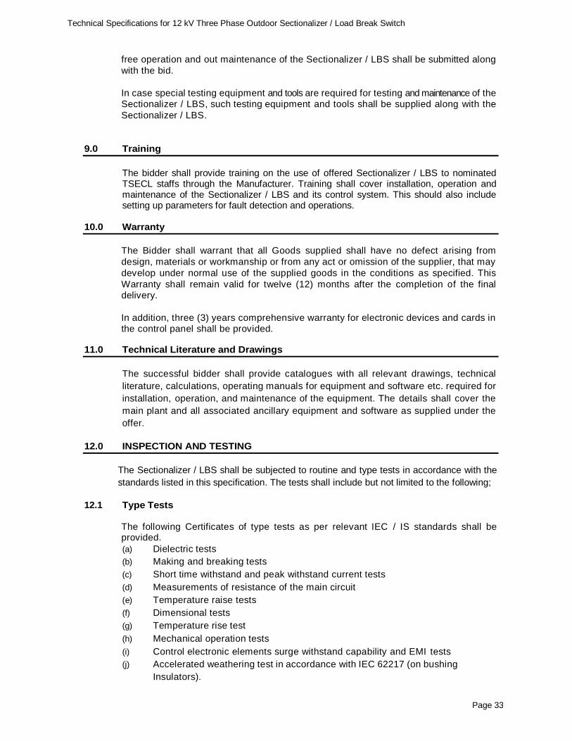
12.0 INSPECTION AND TESTING
The Sectionalizer / LBS shall be subjected to routine and type tests in accordance with the
standards listed in this specification. The tests shall include but not limited to the following;
12.1 Type Tests
The following Certificates of type tests as per relevant IEC / IS standards shall be provided.
(a) Dielectric tests
(b) Making and breaking tests
(c) Short time withstand and peak withstand current tests
(d) Measurements of resistance of the main circuit
(e) Temperature raise tests
(f) Dimensional tests
(g) Temperature rise test
(h) Mechanical operation tests
(i) Control electronic elements surge withstand capability and EMI tests
(j) Accelerated weathering test in accordance with IEC 62217 (on bushing
Insulators).
Page 34
Technical Specifications for 12 kV Three Phase Outdoor Sectionalizer / Load Break Switch
Type test reports should be issued during period not exceeding 5 years from the bid
opening date. In case the type test reports are of the test conducted earlier than 5 (five)
years prior to the date of bid opening, the bidder shall repeat these test(s) at no extra
cost.
Type tests reports shall be from reputed independent CPRI / NABL accredited testing
laboratories in India or reputed international test laboratories accredited to ISO/IEC
17025:2005 for carrying out specified type tests. Proof of accreditation by a national/
international authority shall be forwarded with the offer. The test laboratories should be
acceptable to TSECL.
12.2 Routine Tests
The following Routine Tests in accordance with relevant IEC standards shall be carried
out on all units and test report shall be furnished for the observation of the Engineer
appointed by the purchaser at the time of inspection.
(a) Dielectric test on the main circuit
(b) Measurement of the resistance of the main circuit
(c) Tightness test
(d) Tests on auxiliary and control circuits
(e) Design and visual checks
12.3 Inspection
The Successful bidder shall make necessary arrangements for inspection by TSECL
nominated representative and also to carry out in his presence necessary Acceptance
tests on the Sectionalizer / LBS.
The successful bidder shall give reasonable notice of when the acceptance/sample /routine
tests are to be carried out. TSECL reserves the right to appoint representatives to witness
the tests as well as conduct design reviews, and periodic inspection of the Sectionalizer /
LBS during manufacture.
12.4 Acceptance Tests The following Acceptance/Sample tests as per IEC 62271-111 or equivalent BIS standard shall be witnessed by the TSECL nominated representative;
(a) Dielectric withstand tests
(b) Measurement of resistance of main circuit
(c) Mechanical operation checks
(d) Leakage check
(e) Temperature rise test
(f) Verification of remote operation with the software
(g) Dimensional tests
(h) The Control unit calibration checks, wiring, operating and functional tests
13.0 INFORMATION TO BE FURNISHED BY THE BIDDER
The following shall be furnished with the offer.
Page 35
Technical Specifications for 12 kV Three Phase Outdoor Sectionalizer / Load Break Switch
(a) Catalogues describing the equipment - Sectionalizer / LBS, Control Cabinet,
Software and Auxiliary supply VT.
(b) Literature describing the operational feature of the equipment.
(c) Constructional features, materials used for components and relevant technical
literature.
(d) The following drawings;
i) Overall dimensional drawing of the Sectionalizer / LBS including general
arrangement.
ii) Electrical clearance requirements of installation
iii) Insulator assembly and shed profile
iv) Dimensional drawing of mounting arrangement.
v) Name plate to scale, incorporating the particulars called for.
(e) Manufacturing experience in accordance with clause 7.0
(f) List of Manufacturer Recommended Spare Parts with current prices as per
clause 8.2.
(g) Copies of type test reports as per clause 12.1
(h) Quality Assurance Certification as per clause 6.0.
(i) Completed schedule of guaranteed technical particulars and schedule of
deviations.
Failure to furnish the above information may result in the offer being rejected.
Page 36
Technical Specifications for 12 kV Three Phase Outdoor Sectionalizer / Load Break Switch
ii. minimum actuating-current setting range (phase current)
iii. minimum actuating-current setting range (earth fault current)
iii. Interruption count and Reset
iv. Counts to open setting range
v Inrush-Current Restraint Feature
vi. Response time setting
15 Whether equipment can be used for radial line sectionalizing application.
Page 37
Technical Specifications for 12 kV Three Phase Outdoor Sectionalizer / Load Break Switch
# Parameter Offered
Whether equipment can be used for open ring and ring closing sectionalizing application.
Whether equipment can be used as Load Break Switch
Whether manual locking / unlocking facility by means of a liver mechanism operated using operating rod is available
16 Electrical Endurance
17 Mechanical Endurance
18 Control Cabinet
Enclosure material
Enclosure IP Rating
Provisions for local control and display as specified
Provision for housing RTU / Com. modules
Provision of auxiliary supply via separate VT (IEC 61869-3)
19 Battery Supply
i. Type of Battery
ii. Sealed and maintenance free?
iii. Service life time (Yrs)
iv. No of operations without auxiliary supply
v. Display and low battery voltage signal
vi. Battery hold-up time (hrs)
20 Instrument Transformers (inside bushings)
CT Make and Model
CT Ratio
CT Accuracy
Secondary Amps of the CT
VT Make and Model
Secondary voltage of the VT
21 Material of;
i. Control unit housing / cubicle
ii. Operating mechanism housing
22 Whether the following accessories are provided;
i. Pole steel mounting bracket(s)
ii. Surge arrester mounting brackets on source and load side of Sectionalizer / LBS
iii. Lifting tackle
iv. Earthing terminal
Page 38
Technical Specifications for 12 kV Three Phase Outdoor Sectionalizer / Load Break Switch
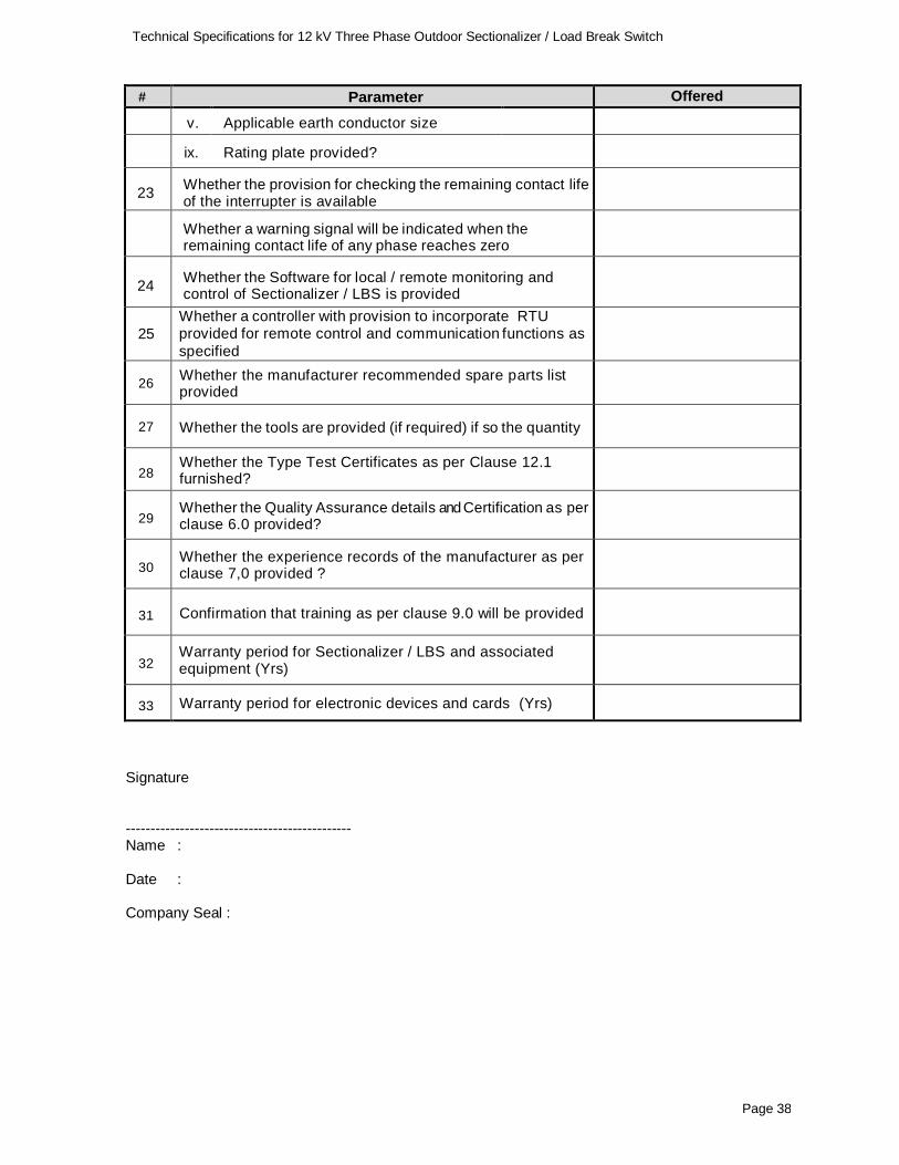
# Parameter Offered
v. Applicable earth conductor size
ix. Rating plate provided?
23 Whether the provision for checking the remaining contact life of the interrupter is available
Whether a warning signal will be indicated when the remaining contact life of any phase reaches zero
24 Whether the Software for local / remote monitoring and control of Sectionalizer / LBS is provided
25
Whether a controller with provision to incorporate RTU provided for remote control and communication functions as
specified
26 Whether the manufacturer recommended spare parts list provided
27 Whether the tools are provided (if required) if so the quantity
28 Whether the Type Test Certificates as per Clause 12.1 furnished?
29 Whether the Quality Assurance details and Certification as per clause 6.0 provided?
30 Whether the experience records of the manufacturer as per clause 7,0 provided ?
31 Confirmation that training as per clause 9.0 will be provided
32 Warranty period for Sectionalizer / LBS and associated equipment (Yrs)
33 Warranty period for electronic devices and cards (Yrs)
Signature ---------------------------------------------- Name : Date : Company Seal :
Page 39
Technical Specifications for 12 kV Three Phase Outdoor Sectionalizer / Load Break Switch
SCHEDULE OF DEVIATIONS
12 kV Three Phase Outdoor Sectionalizer / LBS
# Clause No Details of deviation with justifications
We confirm that there are no deviation apart from those detailed above.
Signature
----------------------------------------------
Name :
Date :
Company Seal :
Technical Specification for Medium Voltage Overhead Line Fault Passage Indicator
Page 40
SPECIFICATION NO : TSE-D-003
Technical Specification for Medium Voltage Overhead Line
Fault Passage Indicator
Rev : R0: 07/2020
Technical Specification for Medium Voltage Overhead Line Fault Passage Indicator
Page 41
Technical Specification for Medium Voltage Overhead Line Fault Passage Indicator
Contents
1. SCOPE 42
2. SERVICE CONDITIONS 42
3. SYSTEM CONDITIONS 42
4. TECHNICAL REQUIREMENTS 43
5. TESTS AND SAMPLES 45
6. SPARE PARTS AND TOOLS 46
7. TECHNICAL SUPPORT 46
8. TRAINING 46
9. NAME PLATE AND LABELLING 46
10. PACKING 46
11. INFORMATION TO BE SUPPLIED WITH THE OFFER 46
12. WARRANTY 47
13. INSPECTION AND TESTING 47
14. QUALITY ASSURANCE 47
15. HAZARDOUS SUBSTANCES 47
Technical Specification for Medium Voltage Overhead Line Fault Passage Indicator
Page 42
Technical Specification for Medium Voltage Overhead Line
Fault Passage Indicator (FPI)
1. SCOPE
This specification covers design, engineering, manufacture, testing, supply, and operation and performance requirements for Medium Voltage Overhead Line Fault Indicator for use in the 33kV and 11kV networks.
The equipment shall conform in all respects to highest standards of engineering, design, workmanship, this specification and the latest revisions of relevant standards at the time of offer and the Purchaser shall have the power to reject any work or material, which, in his judgement, is not in full accordance therewith.
2. SERVICE CONDITIONS
Parameter Value
Max. Ambient Temperature 45 oC
Max. Daily average ambient temp. 35 oC
Min Ambient Temp 0 oC
Maximum Humidity 95%
Minimum Humidity 55%
Maximum altitude above M.S.I. Upto 1000 Meter
Average Annual rainfall 2400 mm.
Isokeraunic (thunder days) level 85 days
Maximum wind speed 55 m/s
(Very high damage risk zone A)
3. SYSTEM CONDITIONS
The equipment shall be suitable for installation in supply systems of the following characteristics:
Parameter 11kV System 33kV System
Nominal Voltage 11kV 33 kV
Highest System Voltage 12kV 36.3 kV
Number of Phases 3 3
Frequency 50Hz 50Hz
Technical Specification for Medium Voltage Overhead Line Fault Passage Indicator
Page 43
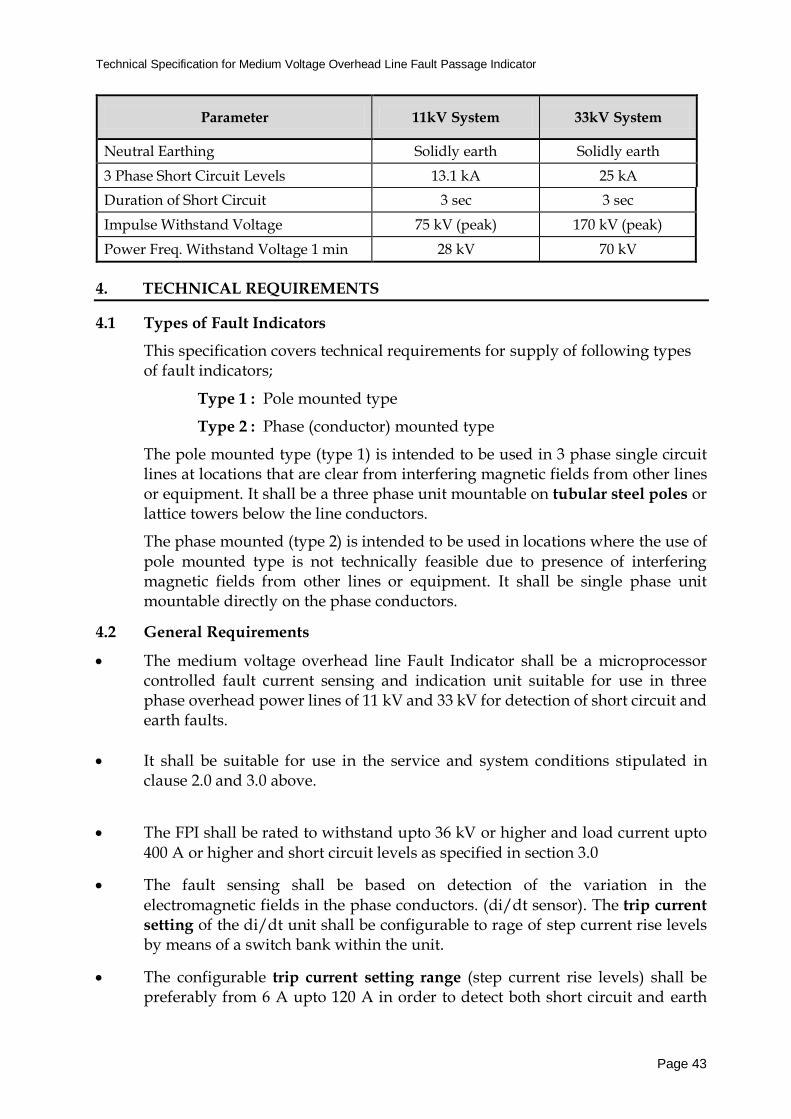
Parameter 11kV System 33kV System
Neutral Earthing Solidly earth Solidly earth
3 Phase Short Circuit Levels 13.1 kA 25 kA
Duration of Short Circuit 3 sec 3 sec
Impulse Withstand Voltage 75 kV (peak) 170 kV (peak)
Power Freq. Withstand Voltage 1 min 28 kV 70 kV
4. TECHNICAL REQUIREMENTS
4.1 Types of Fault Indicators
This specification covers technical requirements for supply of following types of fault indicators;
Type 1 : Pole mounted type
Type 2 : Phase (conductor) mounted type
The pole mounted type (type 1) is intended to be used in 3 phase single circuit lines at locations that are clear from interfering magnetic fields from other lines or equipment. It shall be a three phase unit mountable on tubular steel poles or lattice towers below the line conductors.
The phase mounted (type 2) is intended to be used in locations where the use of pole mounted type is not technically feasible due to presence of interfering magnetic fields from other lines or equipment. It shall be single phase unit mountable directly on the phase conductors.
4.2 General Requirements
The medium voltage overhead line Fault Indicator shall be a microprocessor controlled fault current sensing and indication unit suitable for use in three phase overhead power lines of 11 kV and 33 kV for detection of short circuit and earth faults.
It shall be suitable for use in the service and system conditions stipulated in clause 2.0 and 3.0 above.
The FPI shall be rated to withstand upto 36 kV or higher and load current upto 400 A or higher and short circuit levels as specified in section 3.0
The fault sensing shall be based on detection of the variation in the electromagnetic fields in the phase conductors. (di/dt sensor). The trip current
setting of the di/dt unit shall be configurable to rage of step current rise levels by means of a switch bank within the unit.
The configurable trip current setting range (step current rise levels) shall be preferably from 6 A upto 120 A in order to detect both short circuit and earth
Technical Specification for Medium Voltage Overhead Line Fault Passage Indicator
Page 44
faults depending on the line loading conditions. The range of configurable trip current settings to match line parameters and load conditions of existing power distribution lines will be specifically verified in selection of suitable FPI unit.
The Indicator shall be designed as with inrush restraint and load variation restraint capabilities so that ; i) It shall not respond to any sudden variation (increase/decrease) in load
current. ii) It shall not respond to high magnetising inrush current.
The indicator shall detect short circuit and earth fault currents travelling through the line and provide indication via flashing light. It shall provide flashing light of different colours for permanent and transient faults. Provision to disable transient fault flashing should be provided for saving battery life.
Indicator shall be capable of detecting fault irrespective of the geometric
arrangement of phase conductors. Guidelines for positioning of fault indicators based on the configuration of lines hall be provided.
Additional features such as self-testing of the unit would be preferable.
4.3 Flash Indication and Resetting
The flash indicator shall be of the Neon/Xenon/ LED type and the flash indication shall be visible for at least 250 m distance during day time.
Duration of flashing shall be pre adjustable at least within a range of 2-6 hrs.
The automatic flash indicator resetting shall be provided. Automatic re-setting shall be facilitated based on the following; i) Resetting after line is re-energised. ii) Restoration after load current is restored. iii) Time activated automatic resetting
In addition, availability of manual resetting through remote control or other means would be preferred.
4.4 Equipment Housing and Mounting
The FPI housing shall be made of UV stabilized and flame retarding type, high strength plastic material. The maximum operating temperature for equipment shall not be less than 75° C.
The FPI shall be outdoor type complying to ingress protection level of IP55 or higher.
The mounting accessories suitable for fixing the indicator on tubular type steel poles (for type 1) or on phase conductors (for type 2) shall be provided. In case of conductor mounting, it shall be suitable for mounting on ACSR conductors of
Technical Specification for Medium Voltage Overhead Line Fault Passage Indicator
Page 45
rage of sizes (to be specified). The mounting accessories including brackets, hooks and plates (as required) shall be made of stainless steel or aluminium.
It should be possible to install both types in power lines under live line
(energised) condition. Type 2 shall be mountable on the line using standard hot stick with universal hook. If additional tools are required for installation it should be indicated with the unit prices.
4.5 Power Supply
The power supply for the operation of the electronic components and flash indication of the unit shall be provided through high charge density long life batteries of sufficient capacity suitable for upto 7 years operation.
FPI shall provide ‘low battery’ indication when battery life reachers a threshold level.
4.6 Communication
This specification covers FPI where fault indication shall be provided through flash indication.
The FPIs with in-built communication capability for future application would be preferred. For type 1 FPIs this would be preferably direct communication via SMS / GSM communication to mobile phone / modem / computer server. For type 2 FPIs may be provided with short range RF communication capability to communicate with communication gateway installed nearby for onward transmission through a suitable communication network. Manufacture’s ability to offer equipment and software for future communication application for remote indication of FPI status and other information would be favourably considered.
4.7 Electromagnetic compatibility
The offered FPIs shall conform to the electromagnetic compatibility requirements as specified in IS 14700 including testing requirements.
4.8 Technical Information, Drawings and Manuals
The selected bidder shall supply along with the Indicator relevant drawings, technical literature and manuals including method of installation, operation instructions and maintenance details.
5. TESTS AND SAMPLES
The bidder shall provide demonstration of the functionality of FPIs (including communications) at manufacturer’s facility upon request by TSECL.
Technical Specification for Medium Voltage Overhead Line Fault Passage Indicator
Page 46
The bidder shall agree to provide samples as requested by the TSECL for on-site testing prior to confirmation of the order. Onsite testing may include field testing under simulated earth fault condition as instructed by the Project Manager.
In the event the samples provided by the bidder did not provide satisfactory results as per this specification during on-site testing, the bidder will not qualify for further consideration.
6. SPARE PARTS AND TOOLS
Any tools and spare parts provided free of charge with the supply shall be indicated in the offer. A list of recommended spare parts and tools and recommended stock quantities for 10 years trouble free service of the equipment shall be furnished by the bidder together with current prices of each item in the list.
7. TECHNICAL SUPPORT
The bidder shall provide necessary technical advice to TSECL engineers for installation and commissioning of the equipment without any additional cost.
8. TRAINING
The bidder shall arrange training programme on installation, testing, commissioning, operation and maintenance of the equipment at the manufacturer’s facility.
9. NAME PLATE AND LABELLING
Each equipment shall carry a weather and corrosion proof name plate indicating the following particulars.; a) Manufacturer's identification b) Model and serial numbers c) Voltage level applicable and frequency
d) Applicable standards e) Year of manufacture
10. PACKING
Each Indicator shall be suitably packed separately in a bio degradable packing material
to withstand rough handling and carry a label indicating the name of item, model/type No. etc. 11. INFORMATION TO BE SUPPLIED WITH THE OFFER
The following information shall be furnished with the offer;
Technical Specification for Medium Voltage Overhead Line Fault Passage Indicator
Page 47
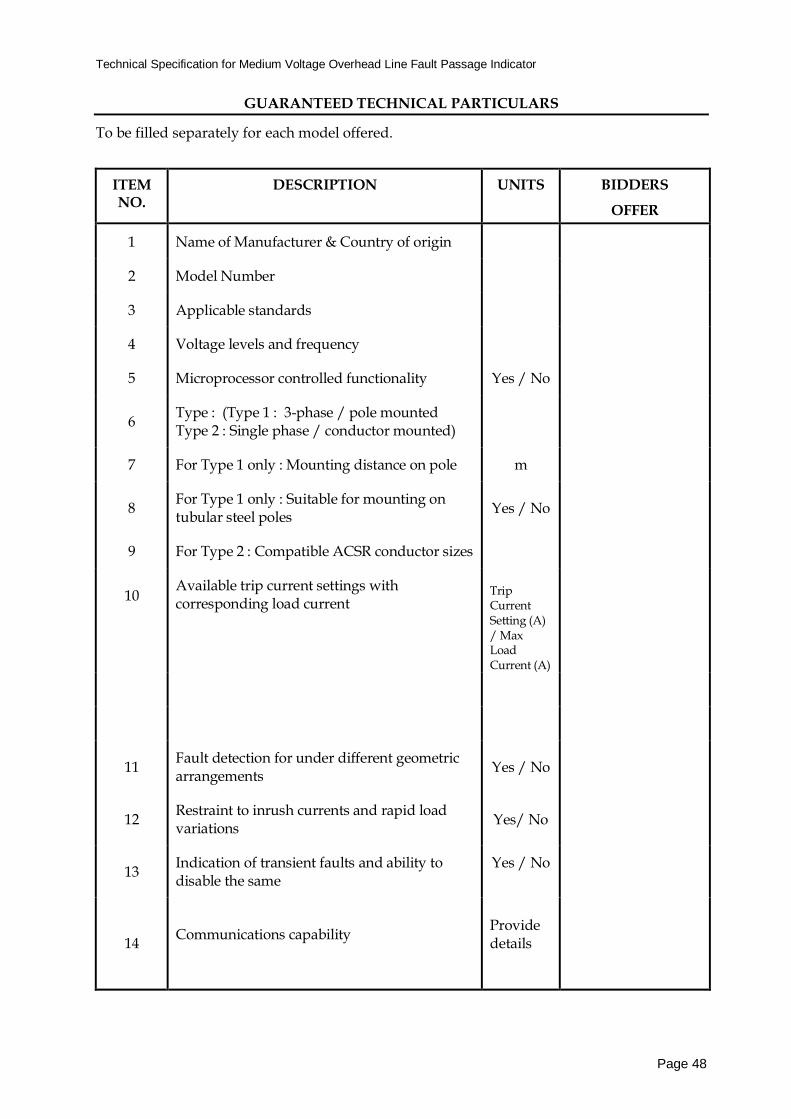
a) Catalogues describing the technical features of the equipment and indicating the Model Number.
b) Completed Schedules of Guaranteed Technical Particulars and Deviations.
c) Test certificates as per applicable standards and performance / factory test certificates confirm the compliance to relevant standards and operational performance of the equipment.
d) A list of clients to whom offered model has been supplied by the bidder previously together with details of supply and contact information.
12. WARRANTY
The selected bidder shall agree to provide warranty against any manufacturing defects for a period of at least one year from the date of supply and acceptance by the TSECL.
13. INSPECTION AND TESTING
The selected Bidder shall agree to make necessary arrangements for inspection by representatives appointed by the TSECL and also to carry out in his presence necessary performance tests / demonstration to confirm the operation of the equipment as per requirements of this specification.
14. QUALITY ASSURANCE
The bidder shall provide documentary evidence of manufacturer’s quality assurance system that is followed during design, production and testing process which shall be acceptable to the TSECL. The availability of valid ISO 9000 quality assurance certification would be favourably considered in this respect.
15. HAZARDOUS SUBSTANCES
The selected bidder shall agree to submit safety data sheets for all hazardous substances used with the equipment. The bidder shall give an assurance that there are no other substances classified as hazardous in the equipment supplied. The bidder shall accept responsibility for the disposal of such hazardous substances, should any be found.
The bidder shall be responsible for any injuries resulting from hazardous substances due to non-compliance with these requirements.
Technical Specification for Medium Voltage Overhead Line Fault Passage Indicator
Page 48
GUARANTEED TECHNICAL PARTICULARS
To be filled separately for each model offered.
ITEM NO.
DESCRIPTION UNITS BIDDERS
OFFER
1 Name of Manufacturer & Country of origin
2 Model Number
3 Applicable standards
4 Voltage levels and frequency
5 Microprocessor controlled functionality Yes / No
6 Type : (Type 1 : 3-phase / pole mounted Type 2 : Single phase / conductor mounted)
7 For Type 1 only : Mounting distance on pole m
8 For Type 1 only : Suitable for mounting on tubular steel poles
Yes / No
9 For Type 2 : Compatible ACSR conductor sizes
10
Available trip current settings with corresponding load current
Trip Current Setting (A) / Max Load Current (A)
11 Fault detection for under different geometric arrangements
Yes / No
12 Restraint to inrush currents and rapid load variations
Yes/ No
13 Indication of transient faults and ability to disable the same
Yes / No
14
Communications capability
Provide details
Technical Specification for Medium Voltage Overhead Line Fault Passage Indicator
Page 49
ITEM NO.
DESCRIPTION UNITS BIDDERS
OFFER
Flash Indication
15 Type (neon/xenon/LED)
16 Visibility
During day time m
During night time m
17 Resetting of flash indication
Automatic (voltage restoration)
Automatic (line current restoration)
Automatic time activated / setting range
Manual
Yes/ No
Yes/ No
Hrs
Yes/ No
Equipment Housing and Mounting
18 Dimensions
19 Housing material
20 IP rating
21 Max. operating temperature °C
22 Weather mounting accessories suitable for fixing on tubular steel poles / conductors provided
Yes/ No
23 Additional tools required for mounting? Yes/ No
Power Supply
20 Type of battery
21 Capacity Ah
22 Maintenance free type Yes/ No
23 Service Life Yrs
24 Min operating time of FPI before replacement of batteries
Hrs
25 Low battery level indication ? Yes / No
Technical Specification for Medium Voltage Overhead Line Fault Passage Indicator
Page 50
ITEM NO.
DESCRIPTION UNITS BIDDERS
OFFER
26 In case of re-chargeable type batteries are provided provide details of on-service charging mechanism (For type 1 only)
Other Information
27 Warranty Period Years
28 Drawings and technical literature included Yes / No
27 Agreement for provision of samples for onsite testing
Yes/ No
28 Agreement for provision of necessary technical support, testing and training
Yes / No
29 List of recommended spare parts and tools included
Yes / No
30 List of references (previous supply) included Yes / No
Signature
----------------------------------------------
Name :
Date :
Company Seal :
Technical Specification for Medium Voltage Overhead Line Fault Passage Indicator
Page 51
SCHEDULE OF DEVIATIONS
(To be completed by the bidder)
# Clause No Details of deviation with justifications
We confirm that there are no deviation apart from those detailed above.
Signature
----------------------------------------------
Name :
Date :
Company Seal :
Page 52
SPECIFICATION NO : TSE-D-004
TECHNICAL SPECIFICATIONS FOR
CABLE FAULT LOCATION AND TEST VAN
Rev 0 07/2020
Page 53
Technical Specifications Cable Fault Location and Test Van
TECHNICAL SPECIFICATION FOR CABLE FAULT LOCATION AND TEST VAN
CONTENTS
1.0
Scope
2.0
System Parameters
3.0
Service Conditions
4.0
Applicable Standards
5.0
Technical Requirements
6.0
Quality Assurance
7.0
Manufacturing Experience
8.0
Spares
9.0
Training
10.0
Warranty
11.0
Technical Literature and Drawings
12.0
Inspection and Testing
13.0
Information to be Furnished by the Bidder
Page 54
Technical Specifications Cable Fault Location and Test Van
TECHNICAL SPECIFICATION FOR CABLE FAULT LOCATION AND TEST VAN
1.0 SCOPE
This specification covers design, manufacture, assembly, testing at manufacturer's works, supply,
delivery, installation & commissioning of Single Phase Modular Cable Fault Locating Test Van
suitable testing and fault locating low /medium voltage power cables up to 33 KV complete with
The Test Van shall be provided with all equipment, instrument and devices for carrying out functions /
procedures indicated above to provide complete, reliable and accurate functionality as specified. This
should include but not limited to Test Instruments, Surge Generators, Signal Generators, Transmitters
and Receivers, Filters, Couplers, Measuring Devices, Protective Equipment, Cables, Probes,
Accessories and Tools. Test Van shall be a self-contained unit where no other external devices or
accessories shall be required to carry out specified functions.
All test instruments shall be offered from the same manufacturer in order to ensure compatibility and
reliability of the functional performance.
The bidder shall submit a list of all key equipment with make & model numbers and brief specifications
supplied with the test van.
5.4 Portable Equipment
The portable equipment such as transmitters and receivers to be supplied with the Test Van shall comply with following technical requirements.
# Function / Procedure Portable Equipment – Technical Requirements
1 Acoustic Pinpointing
Surge Wave Reviver : Acoustic pinpointing reviver shall be supplied with all devices and accessories including display unit (colour), sensor unit, headphones, telescopic handle, measuring tips, carry bag, operating manual etc.
It shall be provided with fault direction indication, background noise reduction, auto-proximity mute features.
2 Step Voltage Pinpointing
Earth Fault Locator : The receiver shall be capable of measuring voltage gradient by earth fault in cable sheath to locate the fault point. It shall be provided with the receiver and color display, 2 nos insulated earth electrodes and connection cables, carry bag and operating manual.
3 Cable Tracing
AF Generator / Receiver Set : The set shall include AF Generator upto 50W, AF Receiver, Connection Cables, Charger, Search Coil, Headphones, Carrying Bags and
Page 57
Technical Specifications Cable Fault Location and Test Van
# Function / Procedure Portable Equipment – Technical Requirements
other accessories. The AF Generator shall be provided with display, frequency selection and auto impedance adjustment. The AF Receiver system shall provide signal direction, direction arrow indications for cable proximity and speaker function for easy cable locations. It shall also be provided with GPS receiver (high accuracy) and facility to save data including GPS coordinates in memory.
6 Cable Identification
CI Generator / Receiver Set : The set shall include CI Generators, CI Receiver, Field sensor, phase identification sensor, test leads,, mains cables, charger, carrying case and operating manuals.
5.5 Control System
The operation and control of fault identification, pre-location, fault conditioning, pinpointing and cable
testing functions shall be provided via centralized control system through an integrated software driven
system.
The personal computer system shall have following minimum configuration: processor - Intel I5 or
The control system software shall be menu driven operated via touch screen or rotary knobs. The
system shall facilitate saving and backing up all data in a relational database system. Software updates
shall be provided free of charge during the period of warranty.
The operator console shall be provided with a table with drawers, computer stands, rotating chair and
storage cabinets and electrical lighting. The control console and instrument sections shall be provided
with air-conditioning.
5.6 Power Supply
The system should work on input supply of 220 V ± 10%. 50 Hz single phase supply. Suitable
control and protection system and should be incorporated in power supply system.
Mains supply shall be provided via following arrangements operating through the alternator /
battery system of the test van;
Generator Set 5 kVA – Van mounted
Electronic Power Generator – Van mounted
5.7 Safety and Protection Equipment
The Test Van shall be installed with safety system including automatic checks interlocking circuit, built
in forced discharge circuit. High voltage can be prepared only after all prerequisites are checked by
the safety circuit so as to ensure that no damage is caused to the equipment. The safety system shall
also include earth monitoring, discharge system monitoring, supply voltage protection including over /
under voltage protection, RCCB.
Page 58
Technical Specifications Cable Fault Location and Test Van
The control unit should provide a visual indication of failure of safety circuits/incorrect selection etc.
with possible corrective methods. Constant monitoring of all safety circuits such as earth monitoring
circuit safety interlock monitoring etc. should be inbuilt into the control unit.
5.8 Cable System
All the cables required for the operation of the system shall be provided with 50 m length mounted on
suitable drums with lockable brakes. This should include high voltage cables, mains cable, ground
cable, RF cable (TDR) and auxiliary cable as per requirement
5.9 Vehicle
All equipment and systems shall be assembled in a van or mini truck conforming to the motor traffic
act of India. It shall be brand new and latest model of a reputed make available in India, serviceable
and maintainable in north-east India.
The test van / vehicle shall comply with following minimum specifications:
Engine : Four cycle, in-line, water cooled, diesel or petrol engine.
Gear system : Manual or automatic synchro-mesh transmission or suitable gear system
compatible to clutch system with four forward and one reverse speed.
Drive : Rear wheel or four wheel
Steering : Power Steering system with steering lock.
Breaks : Power assisted hydraulic system for front and rear wheels and parking break on
transmission.
Electrical system :12 or 24 volts electrical system with heavy duty battery and alternator charging
System.
Assembly : The Cable testing Equipment except portable items shall be permanently fixed to
the system in a convenient and orderly manner. The equipment shall be
accessible from the rear door of the cable testing van.
Spares : Following spares should be supplied ;
a) Spare Wheel
b) Wheel brace.
c) Hydraulic jack.
d) Owner's hand book and operation and periodic maintenance manuals in
English.
e) Set of Spanners, Screw drivers and Pliers
Availability of spare parts should be guaranteed for 05 years
Availability of manufacturer authorized service centers and repair services in Tripura shall be
confirmed. Details of the Authorized agents, repair facilities/workshops available in Tripura shall be
provided.
6.0 Quality Assurance
The manufacturer shall have an established quality assurance system in the process of
design, manufacture and testing of equipment. The bidder shall furnish related quality
system details and Quality Assurance Certifications such as ISO certifications, along
with the offer.
7.0 Manufacturing Experience
Page 59
Technical Specifications Cable Fault Location and Test Van
The manufacturer shall have minimum of 10 years of experience in manufacturing similar
products. The product offered shall have been in service in electricity utilities over past 3
years.
The bidder shall furnish list of purchasers with year and quantity of the product offered
along with the bid to prove his manufacturing experience.
8.0 Tools and Spares
8.1 Tools
The following tools shall be provided;
• Discharging Rods • Measuring Wheel • Earth Spikes • Megger 0-10 KV (5 mA short Circuit Current) • Set of spanners, screw drivers etc.
Any other tool not mentioned above but otherwise required should also be supplied 8.2 Manufacturer Recommended Spare Parts
A list of manufacturer recommended spare parts with current prices for 5 year trouble
free operation and maintenance of the equipment shall be submitted along with the bid.
9.0 Training
The bidder shall provide training on the use of offered Test Van to nominated TSECL staffs through the Manufacturer. Training shall cover operation of all equipment and control system for carrying out specified functionalities and methods for fault location and testing of cables.
10.0 Operation of Equipment
The supplier shall post one trained person per test van at their own cost for operation of the
cable fault locating and testing system for one year in Tripura. During this period the person
should operate the equipment to locate cable faults as appear from time to time. At the same
time he should provide on the job training to the engineers/technicians of the TSECL. The
supplier shall make own arrangements for his boarding, lodging, travel etc.
11.0 Guarantee
The Bidder shall warrant that all Goods supplied shall have no defect arising from design, materials or workmanship or from any act or omission of the supplier that may develop
under normal use of the supplied goods in the conditions as specified. This guarantee shall remain valid for three years after the completion of the final delivery.
In addition, the bidder shall provide three (3) years or 100,000 km comprehensive
warranty for the test van / mini-truck.
12.0 Performance Guarantee
The bidder is also required to provide Performance Guarantee for proper operation and
outcome of the equipment in carrying out specified functionalities and methods for a
period of one year. Bidder is liable for penalties as indicated in the bid document f or any failure against this performance guarantee.
Page 60
Technical Specifications Cable Fault Location and Test Van
13.0 Technical Literature and Drawings
The successful bidder shall provide catalogues with all relevant drawings, technical
literature, calculations, operating manuals for all equipment and software etc. supplied
with the Test Van. The details shall cover the main plant and all associated ancillary
equipment and software as supplied under the offer.
14.0 INSPECTION
TSECL reserves the right to inspect all equipment and Test Vehicle at the manufacturer’s
works prior to shipment. The equipment shall not be shipped without clearance from the
TSECL or its authorized representative.
15.0 INFORMATION TO BE FURNISHED BY THE BIDDER
The following shall be furnished with the offer as applicable.
(a) Catalogues describing the equipment
(b) List of equipment and specifications as per clause 5.3..
(c) Safety instructions.
(d) Shop drawings
(e) Manufacturing experience in accordance with clause 7.0
(f) List of Manufacturer Recommended Spare Parts with current prices as per clause
8.2.
(g) Quality Assurance Certifications as per clause 6.0.
(h) Guarantees
(i) Completed schedule of guaranteed technical particulars and schedule of
deviations.
Failure to furnish the above information may result in the offer being rejected.
Page 61
Technical Specifications for 12 kV Ring Main Units
SPECIFICATION NO : TSE-D-005
TECHNICAL SPECIFICATIONS FOR
12 kV MOTORIZED RING MAIN UNITS (RMU)
Rev : R0: 07/2020
Page 62
Technical Specifications for 12 kV Ring Main Units
TECHNICAL SPECIFICATION FOR 12 kV MOTORIZED RING MAIN UNITS
12.0 TECHNICAL LITERATURE AND DRAWINGS ................................................................................ 77
13.0 INFORMATION TO BE FURNISHED BY THE BIDDER ..................................................... 77
SCHEDULE OF DEVIATIONS.......................................................................................................... 78
Page 63
Technical Specifications for 12 kV Ring Main Units
TECHNICAL SPECIFICATION FOR 12 KV MOTORIZED RING MAIN UNITS
1.0 SCOPE
This specification covers the design, manufacture, testing, supply, and delivery and performance requirements of Ring Main Units (RMU) for use in 11 kV underground distribution networks in Tripura for indoor and outdoor applications. RMUs will be installed and operated under the system and service conditions indicated below. RMUs shall be offered in accordance with the requirements of this specification and latest versions of the standards listed herein. 2.0 SYSTEM PARAMETERS
Parameter 11kV System
Nominal Voltage 11kV
Highest System Voltage 12kV
Number of Phases 3
Frequency 50Hz
Neutral Earthing Effectively earthed
3 Phase Short Circuit Levels 12.5 kA
Duration of Short Circuit 1sec
Impulse Withstand Voltage 75 kV (peak)
Power Freq. Withstand Voltage 1 min 28 kV
3.0 SERVICE CONDITIONS
Parameter Value
Max. Ambient Temperature 45 oC
Max. Daily average ambient temp. 35 oC
Min Ambient Temp 0 oC
Maximum Humidity 95%
Minimum Humidity 55%
Maximum altitude above M.S.I. Upto 1000 Meter
Average Annual rainfall 2400 mm.
Isokeraunic (thunder days) level 85 days
Maximum wind speed 55 m/s
(Very high damage risk zone A)
Page 64
Technical Specifications for 12 kV Ring Main Units
4.0 APPLICABLE STANDARDS
Unless otherwise specified herein, all equipment shall be designed, manufactured and supplied
in accordance with the relevant current IS and IEC Standards including all amendments.
IEC/ISO IS Subject
IEC 62271-1:2017 IS/ IEC 62271-1 High-voltage switchgear and controlgear - Part 1: Common specifications for alternating current switchgear and controlgear
IEC 62271-200:2011 / COR1:2015
IS/ IEC 62271-1 High-voltage switchgear and controlgear - Part 200: AC metal-enclosed switchgear and controlgear for rated voltages above 1 kV and up to and including 52 kV
IEC 62271-201:2014 IS / IEC 62271-201
High-voltage switchgear and controlgear - Part 201: AC solid-insulation enclosed switchgear and controlgear for rated voltages above 1 kV and up to and including 52 kV
IEC 62271-102:2018 IS / IEC 62271-102
High-voltage switchgear and controlgear - Part 102: Alternating current disconnectors and earthing switches
IEC 62271-100: 2008+AMD1:2012+AMD2:2017
IS/ IEC 62271-100
High-voltage switchgear and controlgear - Part 100: Alternating-current circuit-breaker
IEC 62271-103:2011 / COR1:2013
High-voltage switchgear and controlgear - Part 103: Switches for rated voltages above 1 kV up to and including 52 kV
IEC 62271-205 : 208 High-voltage switchgear and controlgear – Part 205: Compact switchgear assemblies for rated voltages above 52 kV
IEC 62271-214:2019
High-voltage switchgear and controlgear - Part 214: Internal arc classification for metal-enclosed pole-mounted switchgear and controlgear for rated voltages above 1 kV and up to and including 52 kV
IEC 60376:2018 BIS IS 13072 Specification of technical grade sulphur hexafluoride (SF6) and complementary gases to be used in its mixtures for use in electrical equipment
IEC 60060:2020 IS / IEC 60060 High-voltage test techniques
IEC 60529: 1989 +AMD1:1999+AMD2: 2013
IS 13947 Degrees of protection provided by enclosures
IEC: 61869 IS 2705 : 1992 Instrument transformers.
IEC: 61869 IS: 3156 Instrument transformers
IEC 62055 Electrical Relays
Page 65
Technical Specifications for 12 kV Ring Main Units
5.0 TECHNICAL REQUIREMENTS
5.1 General
This specification covers the design, manufacture, testing, supply, and delivery and performance
requirements of Ring Main Units (RMU) for use in 11 kV underground distribution networks in Tripura
for indoor and outdoor applications.
5.2 Functional Units and Notations
The following notations will be used in this specification for the purpose of referencing. Same may be
used in BOQs / Price Schedules as per the notations specified herein in the bid documents.
It is noted that different notations or symbols are used by the different RMU manufacturers. The
notation system used in the specification is for reference purpose only and does not imply or favor
any specific makes or models.
Notations for RMU Functional Units (Modules)
Notation Description of functionality
S Ring Main Feeder with Switch disconnnector and earthing switch
B Tee off / Transformer Feeder with Circuit Breaker, disconnector and earthing
switch
Notations for Extensibility of RMUs
Notation Description of functionality
Non extensible (Standard unless otherwise specified)
RE Extensible to right
LE Extensible to left
DE Double Extensible to left or right
Notations for Installation Types
Notation Description of Installation Type
Outdoor, inside Kiosk (Standard unless specified as N)
N Indoor
Page 66
Technical Specifications for 12 kV Ring Main Units
5.2.1 Functional Configurations
The RMUs shall have functional configurations of comprising of any combination of the basic
functional units defined above.
Ex: 3 Way RMUs - SBS
4 Way RMUs - SBBS, SSBS
5 Way RMUs - SSBBS, SBBBS,
6 Way RMUs - SBBBSS
5.2.2 Notation
The following notation sequence will be used to define required type of RMU in this specification as
Rated breaking capacity – cable/line charging A 110
Rated earth fault breaking current A 200
Rated short circuit making current kApk 50
Electrical and mechanical endurance class - E3 / M1
(III) Vacuum Circuit Breaker (For Functional Unit B)
Rated Current A 200 (standard) / 630
Rated short circuit breaking current kA 25
Rated short circuit making current kApk 62.5
Operating sequence - O - 3min - CO - 3min - CO
Electrical and mechanical endurance class for specified operating sequence
- E2 / M1
(IV) Earthing Switch (ES) / Disconnector
Rated Making Current kApk 50
Electrical and mechanical endurance class (ES) - E2 / M0
Disconnector - mechanical endurance class - M0
5.4 RMU Design and Construction 5.4.1 General Requirements
The RMU to be supplied against this specification are required for vital installations where
continuity of service is very important. The design, materials and manufacture of the
equipment shall, therefore, be of the highest order to ensure continuous and trouble free
Page 68
Technical Specifications for 12 kV Ring Main Units
service.
The RMU offered shall be compact, maintenance free, easy to install reliable, safe and easy
to operate and complete with all parts necessary for their effective and trouble-free operation.
Such parts will be deemed to be within the scope of the supply irrespective of whether they
are specifically indicated in the commercial order or not.
The RMU shall be suitable for mounting on plinth and mounted on structure with provision
for cabling through gland plate in the base and trench below. The RMU shall be designed to
be tamper proof so as to prevent access to all live parts during operation without the use of
tools.
The RMU shall be designed so that the position of the different devices is visible to the
operator on the front and operations are also visible.
5.4.2 RMU Tank and Insulation
The tank containing shall be corrosion resistant stainless steel sheet (Grade SS 304 – Non
ferrite, Non Magnetic) of minimum 2.5 mm thickness (as per relevant IS/ IEC). It shall comply
with Internal Arc Classification as specified in Table 1.
The solid dielectric or SF6 gas shall be used as insulation media in accordance with IEC
62271-201/ 62271-200. Accordingly all high voltage live parts except for the cable
connections shall be suitably insulated with solid epoxy (HCEP) or SF6 gas.
In case of SF6 gas insulation; the tank shall meet the 'sealed pressure system' criteria in
accordance with the IEC 62271-200. Accordingly no handling / refilling of gas shall be
required throughout the expected operating life, i.e. 30 years. Sealed pressure systems are
completely assembled, filled and tested in the factory. The maximum leakage rate of SF6
gas shall be lower than 0.1% of the total initial mass of SF6 gas per annum. The filling
pressure for the switchgear shall be just above the atmospheric pressure so as to reduce the
tendency to leak. SF6 gas used for the filling of the RMU shall be in accordance with IEC
60376:2018. It is preferable to fit an absorption material in the tank to absorb the moisture
from the SF6 gas and to regenerate the SF6 gas following arc interruption. There shall be
no requirement to 'top up' the SF6 gas.
The degree of protection for RMU tank shall be IP 67. The Front cover mechanism and cable
cover shall have IP2X degree of protection.
5.4.3 Busbars
The phase and earth busbars made up of copper with ratings as given in Table 1 and
according to relevant IS/IEC standards. The phase bus bars and live parts shall be fully
encapsulated by solid insulation or SF6 gas inside the steel tank. Earthing circuit shall be
provided with visible earthing contacts to enhance operator safety. Provision shall be made
on end of RMU for connecting the earth bus to the earth grid by erecting suitable 2 earth
pipes / earth rods.
5.4.4 Functional Unit S
The functional unit S (Ring Main Feeder Unit) shall be equipped with fault making / load
Page 69
Technical Specifications for 12 kV Ring Main Units
breaking spring assisted ring Switch Disconnector and integral earth switch complying with
ratings provided in Table 1.
In case of solid insulated RMU, unit shall be provided with vacuum type load break switch,
disconnector and earth switch with ratings as indicated in Table 1.
The Switch Disconnector and earth switch shall comply with the requirements specified in
IEC 62271-102 and 103.
The switch disconnector shall be provided with motorized operating mechanism and
compatible for remote operation in future with SCADA integration. Mechanism for manual
operation shall also be provided.
LBS operation counter and local remote control selection switch shall be provided. It shall be
provided with 2NO + 2 NC auxiliary contacts.
Earthing switch shall have manual operating mechanism and provided with 1NO+1NC
auxiliary contacts.
Interlocking shall be provided as indicated in section 5.4.11.
5.4.5 Functional Unit B
The functional unit B (Tee off / Transformer Feeder Unit) shall be equipped with Vacuum
Circuit Breaker (VCB), Disconnector and Earth Switch complying with ratings provided in
Table 1.
The VCB, Disconnector and Earth Switch shall comply with the requirements specified in
IEC 62271-100 and 102 and 103.
The VCB shall be provided with motorized operating and spring charged mechanism and
compatible for remote operation in future with SCADA integration. Local remote control
selection switch shall be provided. It shall be fitted with a local system for manual tripping by
an integrated push button. VCB shall be provided with 4NO+4NC Auxiliary contacts and
operations counter.
The circuit breaker shall be associated with an integrated protection unit that will operate
without any auxiliary power supply and shall include three toroid current transformers
incorporated in the cable chamber as per manufacturer standard type test design. The CT
settings shall be adjustable according to site requirements . Protection core CT complete
details should be furnished (Burden, class, ALF).
An electronic relay self-powered through CTs, a low energy release, and a "fast-on” test
receptacle for protection testing (with or without CB tripping) shall be provided. The protection
system shall ensure circuit breaker tripping as of a minimum operating current which is the
rated current of the feeder to be protected.
Earthing switch / Disconnector shall have manual operating mechanism and provided with
1NO+1NC auxiliary contacts. Disconnector shall be provided with 2NO+2NC Auxiliary
contacts.
Page 70
Technical Specifications for 12 kV Ring Main Units
Interlocking shall be provided as indicated in section 5.4.11
5.4.6 Protection Relays (for functional unit B)
The relay shall be provided with Phase protection of Definite time/ IDMT element for
overcurrent and earth fault with minimum PSM-0.05,Tsm-0.01 having standard
characteristics of Standard Inverse, Very inverse, Extremely Inverse as per IEC 60255-3
standard. The Earth Fault Protection shall be provided of Definite time/ IDMT element having
standard characteristics of Standard Inverse, Very inverse, Extremely Inverse as per IEC
60255-3 standard. The "Time Multiplier" with minimum set point of 0.05 TMS shall be
available. The breaker shall have the provision of LED indication of Trip on Fault High set
(DT) for overcurrent and earth fault-min current setting-0.5 In, minimum Time Delay- 20
milliseconds. The relays shall be suitable numerical relay with necessary elements.
On this basis, the relay as a minimum shall provide:
a) Phase Over Current Protection: (50/51)
b) Earth Fault Protection: (50N/51N)
The relay shall also be provided with:
- Alphanumeric Liquid Crystal Display (LCD)
- Parameter change capability that is password protected
- Capability to record up to 5 of the latest fault records duly time stamped and stored in
- non-volatile memory for subsequent reading via the above referred RS485/RS 232 port
5.4.7 Instrument Transformers and Voltage Sensors
3 nos ring type, single core CTs and 3 phase-earth VTs with fuse protection shall be provided
in each circuit breaker for protection and metering purpose. The CTs and VTs shall conform
to relevant IS / IEC standards. The design and construction shall be sufficiently robust to
withstand thermal and dynamic stresses during short circuits. Secondary terminals of CTs &
VTs shall be brought out suitably to a terminal block in the RMU LV compartment, which will
be easily accessible for testing and connections.
Appropriate capacity and ratings of CTs and PTs shall be provided in the RMU for protection
and metering (future) purpose. Further protection relays shall be self-powered through the
current transformers (CTs) without requiring an auxiliary power supply to operate. The
metering shall not be in the scope of supplier but the provision and space for installation of
the separate metering enclosure in future shall be available.
The RMU's other CTs/sensors, for other equipment including Fault Passage Indicators
(FPIs), shall be supplied by the FPI manufacturer. These CTs/sensors shall be an integral
part of the FPI’s design to ensure that they properly match the requirements of the FPI.
A voltage sensor shall be provided for all the functional units. It shall provide a signal with an
accuracy of 5% for voltage presence (VPIS) indication. The voltage shall be detected on the
cable side.
5.4.8 Cable Compartment, Bushings and Cable Terminations:
Each cable compartment shall have front access and shall have IP2X degree of protection.
Each compartment shall be provided with three bushings of adequate sizes to terminate the
Page 71
Technical Specifications for 12 kV Ring Main Units
incoming and outgoing cables. Bushings shall be Type C rated for 630 A: 25 kA 1 s, 20 kA 3
s and 62.5 kA peak.
Insulated field disconnectable connectors of Interface type C (recommended by the
manufacturer) shall also be provided for each bushing with required conductor and bi-
metallic connectors to connect single / three core XLPE / Al cable upto cross section of 300
sqmm . This should be the part of supply of accessories under this specification.
5.4.9 Cable Test Facility (CTF):
Separate cable test facilities that are independent of the cable termination enclosure shall
be provided.
It shall be possible to connect cable test equipment (e.g. pressure testing or fault locating
equipment) to the cable via separate cable test facility. If additional injection fingers are
required to connect test instruments to the CTF terminals it should be provided for each
RMU.
Connecting and disconnecting of the cable test leads shall be performed under safe earthed
conditions only. Access to the test terminals of the cable test facility shall only be possible
when the associated earth switch is in the closed EARTH position.
After connecting the test equipment, which must only be possible under safe earthed
conditions, the integrated earth connection shall be removed for testing purposes without
interfering with the connected test equipment. After completing the test procedure the
integrated earth connection must be reconnected without interfering with the test equipment.
The test equipment must be safely removed under full earthed conditions. Under normal
service conditions (live cable and busbar) the test connections must be fully earthed.
Each cable test facility shall be interlocked with its associated earth switch and be capable
of being padlocked to ensure that the test terminals of the cable test facility are not accessible
when the cable is energized. The test terminals must be fully earthed under normal service
conditions, access must only be possible when the panel is switched ON in earthed position.
5.4.10 Indication and Controls
All required indications including the following shall be provided in the front panel;
Open / close the status of the RMU circuit breakers and load break switches.
The health of the power supply, which will include battery failure and low voltage
indications.
Open / closed status of RMU earthing switches.
For SF6 insulated type, low SF6 gas pressure indication.
For circuit breaker relay operations.
Indication of main-circuit fault detected by the RMU's FPI
Voltage presence indication for each functional unit
Local controls for operation of switchgear
Manual operating mechanism for switchgear.
Clearly visible mimic diagram that indicates the different functions and position.
Page 72
Technical Specifications for 12 kV Ring Main Units
5.4.11 Interlocks
Suitable fool-proof mechanical, electrical and key interlock system shall be provided to
ensure safety of equipment and personnel when operating the RMU locally and remotely.
This should include but not limited to suitable electrical and mechanical interlocks to facilitate
following;
Operation of earth switch (ES) is only possible when incoming voltage is not present in
cable and LBS / VCB in the functional unit is open.
Operation of LBS is only possible when ES is open and cable compartment cover is
closed.
Operation of diconnector is only possible with VCB / LBS is open.
Opening cable compartment door is only possible when ES is closed.
Test terminals of the cable test facility are accessible (for connection / disconnection of
test leads before / after testing) only when ES is closed
Provision shall be made available for key-locking or padlocking to prevent unauthorized
access for LBS / CB / ES controls, cable test facility terminals and cable compartment.
5.4.12 Outdoor Enclosure
The RMUs for outdoor installation shall be provided with outdoor enclosure with ingress
protection degree of IP54. They shall also be suitable for conditions in which they will be
exposed to heavy industrial pollution, and high levels of airborne dust. Access to RMU
controls and cable compartments shall be provided via door panels.
The outer enclosure shall be made of CRCA, 2 mm thick with thick glands plates of 3 mm.
The sheet steel and the fabricated parts shall be pretreated using 7 tank process and then
coated by layer of zinc phosphate. A finish coat with high scratch resistance epoxy powder
finish paint shall be applied over the primer. The coat thickness shall be minimum 100
microns +/- 25 micron.
The equipment in the proposed outdoor RMU shall be coated to meet specified climatic
conditions. In this respect, standards such as IEC 60870-2-2 covering equipment, systems,
operating conditions, and environmental conditions shall apply along with IEC60721, which
covers the classification of such conditions.
The enclosure unit shall be powder coating of RAL 7032 Grey to DIN Standard43656.
5.4.13 SCADA Compatibility
The RMU shall be provided with standard interfacing facilities for retrofitting RTUs and
communications gateways for integration with SCADA / DMS systems for remote control,
monitoring and automation. It shall be fully SCADA compatible and provide remote access
and control all functional units with motorized control when in remote control mode.
The communication interfaces shall support standard IEC 101/104, DNP3, IEC 61850 and
Modbus protocols.
It shall also be provided with facility for connection with AMI metering units.
Page 73
Technical Specifications for 12 kV Ring Main Units
5.4.14 Fault Passage Indicator
Fault Passage Indicators (FPI) shall be installed with Functional Unit S (Ring Feeder). In
case of 3 way RMU, FPI shall be provided with one ring feeder unit and in case of 4-6 way
RMUs it shall be provided with at least 2 ring feeder units.
The FPI shall have following functionalities and indication shall be available locally as we as
remotely (when connected with SCADA/ DMS in future);
Indication of phase-phase and phase-earth faults
Display of parameters & adjustable settings for short circuit (200 – 1000A) and earth
fault ( 10 – 150 A)
Settings for time delay for inrush currents
Display of the faulty phase
Display of load current, maximum current for each phase, frequency and direction of
energy flow
Fault passage indication for remote monitoring (SCADA compatible)
The FPI shall be provided with following resetting options;;
Manual reset
Resetting after a set time duration
Resetting on restoration of supply
Provision for remote resetting via communication (future)
The FPI shall be self-powered by suitable means and provided with separate CTs for fault
detection.
5.4.15 Power Supply and Battery
The RMU shall be provided as a self-powered unit, with CPT (Control Power Transformer)
directly connected to the live bus feeding the AC/DC converter and battery charger system
with 230 VAC.
The batteries shall be 24 VDC and capable of providing sufficient power to buffer the load
for more than 48 hours with up to 120 single operations.
The AC/DC converter and battery system shall have sufficient capacity to feed all equipment
in the LV circuit by 24 VDC including the aux relays, switchgear operating mechanisms,
motor coils and communication equipment.
5.4.16 Software
All software required for RMU equipment and communication devices shall be provided.
5.4.17 Accessories and Tools
All accessories and tools required for installation and operation shall be provided with each
RMU. This should include but not limited to the following;
Page 74
Technical Specifications for 12 kV Ring Main Units
Set of interface type C insulated cable connectors for each functional unit
Operating handles
Padlocks and keys
Earthing cables and connectors
CTF injection fingers to connect with cable test equipment leads (if required)
5.4.18 Name Plate & Marking
All the components and operating devices of the RMU shall be provided with durable and
legible nameplates containing all technical parameters. Name plates shall be suitably
embossed with the following information.
Name / address of the manufacturer
Month and year of supply
PO Number
Rated Voltage
System Frequency
RMU Configuration (functional units)
Applicable Rated values
Rated short time withstand current for 3 sec
Rated Impulse and power frequency withstand Voltage
Degree of Protection
Type Designation or Serial no.
Year of manufacture
Mass of unit SF6 gas filling pressure (for SF6 insulated units)
Property of TSECL
A Danger plate / label of appropriate size shall also be provided on the enclosure.
6.0 Inspection and Testing
The RMU shall be subjected to type tests, routine and acceptance tests in accordance with
the standards listed in this specification. The tests shall include but not limited to the following;
6.1 Type Tests
Type test reports should be issued during period not exceeding 5 years from the bid
opening date. In case the type test reports are of the test conducted earlier than 5 (five)
years prior to the date of bid opening, the bidder shall repeat these test(s) at no extra
cost.
Type tests reports shall be from reputed independent CPRI / NABL accredited testing
laboratories in India or reputed international test laboratories accredited to ISO/IEC
17025:2005 for carrying out specified type tests. Proof of accreditation by a national/
international authority shall be forwarded with the offer. The test laboratories should be
acceptable to TSECL.
The following type tests certificates as per relevant IEC / IS standards shall be provided.
Short time current withstand test and peak current withstand test.
Lightening Impulse voltage with-stand test
Page 75
Technical Specifications for 12 kV Ring Main Units
Temperature rise test.
Short Circuit current making and breaking tests.
Power frequency voltage withstand test (dry).
Capacitive current switching test confirming to IEC.
Mechanical operation test.
Measurement of the resistance of the main circuit.
Checking of degree of protection of main tank and outer enclosure
Switch, circuit breaker, earthing switch making capacity.
Switch, circuit breaker breaking capacity.
Internal arc withstands.
Checking of partial discharge on complete unit.
6.2 Routine Tests
The following Routine Tests in accordance with relevant IEC / IS standards shall be carried
out on all units and test report shall be furnished for the observation of the Engineer
appointed by the purchaser at the time of inspection.
Conformity with drawings and diagrams,
Measurement of closing and opening speeds,
Measurement of operating torque
Dielectric testing and main circuit resistance measurement.
Power frequency voltage
Resistance test for the circuit
Mechanical operation tests.
Micro ohm test (contact Resistance test) for the assembly inside the tank
Circuit breaker analyzer test so as to ensure the simultaneous closing of all Poles for
VCB.
Partial Discharge test on the complete tank so as to be assure of the proper insulation
level and high service life.
High voltage withstand.
Secondary tests to ensure the proper functioning of the live line indicators, fault passage
indicators and relays.
For SF6 insulated RMU following tests are also applicable;
Checking of filling pressure,
Checking of gas-tightness,
SF6 gas leak test
6.3 Acceptance Tests
All or selected the tests listed under Routine Tests above shall be carried out as acceptance
test on random samples as per sampling plan under IEC/15 for each lot.
Heat Run Test shall be carried out on one random sample / configuration quantity as
acceptance test.
6.4 Inspection
Page 76
Technical Specifications for 12 kV Ring Main Units
The successful bidder shall make necessary arrangements for inspection by TSECL
nominated representative and also to carry out in his presence necessary Acceptance
tests on the RMU.
The successful bidder shall give reasonable notice of when the acceptance/sample /routine
tests are to be carried out. TSECL reserves the right to appoint representatives to witness
the tests as well as conduct design reviews, and periodic inspection of the RMU during
manufacture.
7.0 Quality Assurance
The manufacturer shall have an established quality assurance system in the process
of design, manufacture and testing of equipment. The bidder shall furnish related quality
system details and Quality Assurance Certifications such as ISO certifications, along
with the offer.
8.0 Manufacturing Experience
The manufacturer of RMU shall have minimum of 10 years of experience in
manufacturing similar products. The product offered shall have been in service in
electricity utilities over past 5 years.
The bidder shall furnish list of purchasers with year and quantity of the product offered
along with the bid to prove his manufacturing experience.
9.0 Spares
9.1 Mandatory Spares and Tools
The following mandatory spare parts shall be provided for every 20 Nos of RMUs or
part thereof.
03 Sets of interface type C insulated cable connectors (3 Nos per set)
01 Nos battery charges
01 Nos motor and gear units
01 Set of operating handles
Bidder shall note that this is in addition to the accessories and tools to be supplied with
each RMU as indicated in clause 5.4.17.
9.2 Manufacturer Recommended Spare Parts
A list of manufacturers recommended spare parts with current prices for 5 year trouble
free operation and out maintenance of the RMU shall be submitted along with the bid.
In case special testing equipment and tools are required for testing and maintenance of the RMU, such testing equipment and tools shall be supplied along with the RMUs.
10.0 Training
The bidder shall provide training on offered RMUs to nominated TSECL staffs through the
Manufacturer. Training shall cover installation, operation and maintenance of the RMU and
its switchgear.
Page 77
Technical Specifications for 12 kV Ring Main Units
11.0 Warranty
The Bidder shall warrant that all Goods supplied shall have no defect arising from design, materials or workmanship or from any act or omission of the supplier, that may
develop under normal use of the supplied goods in the conditions as specified. This
Warranty shall remain valid for thirty six (36) months after the completion of the final delivery.
In addition, three (3) years comprehensive warranty for electronic devices and cards in
the control panel shall be provided.
12.0 Technical Literature and Drawings
The successful bidder shall provide catalogues with all relevant drawings, technical
literature, calculations, operating manuals for equipment etc. required for installation,
operation, and maintenance of the equipment. The details shall cover the main plant and
all associated ancillary equipment and software as supplied under the offer.
13.0 INFORMATION TO BE FURNISHED BY THE BIDDER
The following shall be furnished with the offer.
(a) Schematic diagram of the RMU and design details
(b) Catalogues describing the equipment – RMU and its equipment
(c) Literature describing the operational features of the equipment.
(d) Constructional features, materials used for components and relevant technical
literature.
(e) Overall dimensional drawing of the RMUs offered
(f) Manufacturing experience in accordance with clause 8.0
(g) List of Manufacturer Recommended Spare Parts with current prices as per
clause 9.2.
(h) Copies of type test reports as per clause 6.1
(i) Quality Assurance Certifications as per clause 7.0.
(j) Completed schedule of guaranteed technical particulars and schedule of
deviations.
Failure to furnish the above information may result in the offer being rejected.
Page 78
Technical Specifications for 12 kV Ring Main Units
SCHEDULE OF DEVIATIONS
12 kV Three Phase Outdoor Auto RMU
# Clause No Details of deviation with justifications
We confirm that there are no deviation apart from those detailed above.