78
FOURTH EDITION Volume IV: Duraplus TM ABS Industrial Piping System Industrial Technical Manual Series IPEX DURAPLUS TM ABS INDUSTRIAL PIPING SYSTEMS

F O U R T H E D I T I O N
Volume IV:Duraplus
TM
ABSIndustrialPiping System
Industrial TechnicalManual Series
IPEX DURAPLUS TM ABS INDUSTRIALPIPING SYSTEMS
DuraplusTM ABS Industrial Piping System
Industrial Technical Manual Series
Vol. IV, 4th Edition
© 2013 by IPEX. All rights reserved. No part of this book may be used or reproduced in any manner whatsoever without priorwritten permission. For information contact: IPEX, Marketing, 2441Royal Windsor Drive, Mississauga, Ontario, Canada, L5J 4C7.
The information contained here within is based on currentinformation and product design at the time of publication and issubject to change without notification. IPEX does not guarantee orwarranty the accuracy, suitability for particular applications, orresults to be obtained therefrom.

ABOUT IPEX At IPEX, we have been manufacturing non-metallic pipe and fittings since 1951. We formulate our own compounds andmaintain strict quality control during production. Our products are made available for customers thanks to a network ofregional stocking locations throughout North America. We offer a wide variety of systems including complete lines of piping,fittings, valves and custom-fabricated items.
More importantly, we are committed to meeting our customers’ needs. As a leader in the plastic piping industry, IPEXcontinually develops new products, modernizes manufacturing facilities and acquires innovative process technology. In addition,our staff take pride in their work, making available to customers their extensive thermoplastic knowledge and field experience.IPEX personnel are committed to improving the safety, reliability and performance of thermoplastic materials. We are involved inseveral standards committees and are members of and/or comply with the organizations listed on this page.
For specific details about any IPEX product, contact our customer service department.

iDuraplus ABS Industrial Piping System
CAUTION: Do not use or test the products in this manual with compressed air or other gases including air-over-water-boosters
SAFETY ALERTS
Engineered thermoplastics are safe inert materials that do not pose any significant safety or environmental hazards duringhandling or installation. However, improper installation or use can result in personal injury and/or property damage. It isimportant to be aware of and recognize safety alert messages as they appear in this manual.
The types of safety alert messages are described below.
This safety alert symbol indicates important safety messages in thismanual. When you see this symbol be alert to the possibility of personalinjury and carefully read and fully understand the message that follows.
WARNING
Note: The use of the word “NOTE” signifies special instructions which are important but are not related to hazards.
“CAUTION” identifies hazards or unsafe practices thatcan result in minor personal injury or product orproperty damage if instructions, includingrecommended precautions, are not followed.
“WARNING” identifies hazards or unsafe practices thatcan result in severe personal injury or death ifinstructions, including recommended precautions, arenot followed.
CAUTION
• NEVER use compressed air or gas in PVC/CPVC/PP/PVDF pipe and fittings.
• NEVER test PVC/CPVC/PP/PVDF pipe and fittings with compressed air or gas, or air-over-water boosters.
• ONLY use PVC/CPVC/PP/PVDF pipe for water and approved chemicals.
CAUTION WARNING
For the materials described in this manual, the following warming applies.
Use of compressed air or gas in PVC/CPVC/PP/PVDF pipe and fittings can resultin explosive failures and cause severe injury or death.

ii Duraplus ABS Industrial Piping System
CAUTION: Do not use or test the products in this manual with compressed air or other gases including air-over-water-boosters
This page intentionally
left blank

Contents
DuraplusTM ABS Industrial Piping System Manual
About IPEX
Safety Alerts . . . . . . . . . . . . . . . . . . . . . . . . . . . . . . . . . . . . . . . . . . . . . . . . .i
Section One: General Information
Overview . . . . . . . . . . . . . . . . . . . . . . . . . . . . . . . . . . . . . . . . . . . . . . . . . . .1
Duraplus Characteristics . . . . . . . . . . . . . . . . . . . . . . . . . . . . . . . . . . . . . . . .1
Applications . . . . . . . . . . . . . . . . . . . . . . . . . . . . . . . . . . . . . . . . . . . . . . . . .2
Secondary Refrigerants Used With Duraplus Industrial ABS . . . . . . . . . . . . .3
Selecting Compatible Glycols for Use with Duraplus Industrial ABS . . . . . . .3
Suitability of Glycols for Use with ABS . . . . . . . . . . . . . . . . . . . . . . . . . . .4
Section Two: Material Properties
Material Composition . . . . . . . . . . . . . . . . . . . . . . . . . . . . . . . . . . . . . . . .5
Impact Strength . . . . . . . . . . . . . . . . . . . . . . . . . . . . . . . . . . . . . . . . . . . .5
Toxicity . . . . . . . . . . . . . . . . . . . . . . . . . . . . . . . . . . . . . . . . . . . . . . . . . .5
Thermal Properties . . . . . . . . . . . . . . . . . . . . . . . . . . . . . . . . . . . . . . . . . .6
Mode of Failure . . . . . . . . . . . . . . . . . . . . . . . . . . . . . . . . . . . . . . . . . . . .6
Chemical Resistance . . . . . . . . . . . . . . . . . . . . . . . . . . . . . . . . . . . . . . . .6
Section Three: Design Data
System Sizes and Pressure Ratings . . . . . . . . . . . . . . . . . . . . . . . . . . . . . .7
Pressure/Temperature Relationship . . . . . . . . . . . . . . . . . . . . . . . . . . . . . .7
General Principles of Design and Support . . . . . . . . . . . . . . . . . . . . . . . . . . . .8
Expansion and Contraction . . . . . . . . . . . . . . . . . . . . . . . . . . . . . . . . . . . . . .9
Pipe Sizing . . . . . . . . . . . . . . . . . . . . . . . . . . . . . . . . . . . . . . . . . . . . . . . .12
Head Loss in Pipe – Conveying High Viscosity Liquids . . . . . . . . . . . . . . . . . .13
Head Loss in Fittings – Equivalent Pipe Length . . . . . . . . . . . . . . . . . . . . . . .14
Pressure Drop Across Valves . . . . . . . . . . . . . . . . . . . . . . . . . . . . . . . . . . . .15
Section Four: Handling and Installation
Solvent Cement Welding . . . . . . . . . . . . . . . . . . . . . . . . . . . . . . . . . . . . . . .21
Joint Curing Time . . . . . . . . . . . . . . . . . . . . . . . . . . . . . . . . . . . . . . . . . . . .25
Branch Connections . . . . . . . . . . . . . . . . . . . . . . . . . . . . . . . . . . . . . . . . . .26
Threaded Connections . . . . . . . . . . . . . . . . . . . . . . . . . . . . . . . . . . . . . . . . .29
Installation of Buried Pipe . . . . . . . . . . . . . . . . . . . . . . . . . . . . . . . . . . . . . .31
Installed Exposure to Sunlight . . . . . . . . . . . . . . . . . . . . . . . . . . . . . . . . .31
iiiDuraplus ABS Industrial Piping System
CAUTION: Do not use or test the products in this manual with compressed air or other gases including air-over-water-boosters

iv Duraplus ABS Industrial Piping System
CAUTION: Do not use or test the products in this manual with compressed air or other gases including air-over-water-boosters
Testing . . . . . . . . . . . . . . . . . . . . . . . . . . . . . . . . . . . . . . . . . . . . . . . . . . .32
Storage . . . . . . . . . . . . . . . . . . . . . . . . . . . . . . . . . . . . . . . . . . . . . . . . . . .32
Warnings . . . . . . . . . . . . . . . . . . . . . . . . . . . . . . . . . . . . . . . . . . . . . . . . . .33
Section Five: Valves
VKD Series Ball Valves . . . . . . . . . . . . . . . . . . . . . . . . . . . . . . . . . . . . . . . .34
FK Series Butterfly Valves . . . . . . . . . . . . . . . . . . . . . . . . . . . . . . . . . . . . . .37
VM Series Diaphragm Valves . . . . . . . . . . . . . . . . . . . . . . . . . . . . . . . . . . . .40
Single Union Ball Check Valves . . . . . . . . . . . . . . . . . . . . . . . . . . . . . . . . . .42
RV Series Sediment Strainers . . . . . . . . . . . . . . . . . . . . . . . . . . . . . . . . . . .43
Section Six: Dimensional Data
Dimensions . . . . . . . . . . . . . . . . . . . . . . . . . . . . . . . . . . . . . . . . . . . . . . . .46
Section Seven: Specifications
Sample Specification . . . . . . . . . . . . . . . . . . . . . . . . . . . . . . . . . . . . . . . . .63
Appendix A: Conversion Charts . . . . . . . . . . . . . . . . . . . . . . . . . . . . . . . . . . . . . . . . .65

The DuraplusTM Industrial Piping System by IPEX offers acomplete range of ABS pressure pipe, valves and fittings thatare ideal for demanding applications ranging from abrasiveslurries and separation reagents to caustic processes and lowtemperature glycol systems. These rugged Durapluscomponents operate over a wide range of temperatures whiledelivering excellent material properties including:
• Exceptional Toughness
• Non-Toxicity
• Corrosion Resistance
This design and installation manual provides the most up-to-date comprehensive information about IPEX’s DuraplusABS Industrial Piping System. By combining IPEX’slaboratory test results with over 50 years of field experience,we have produced a manual suited to engineers, contractorsand distributors alike. All aspects of Duraplus are describedhere – from basic raw material properties through toinstallation procedures of the finished product.
IPEX offers matched Duraplus pipes, fittings and valves inIPS sizes ranging from 3/8" to 12" nominal diameter, suitablefor pressures up to 230 psi at 73°F (23°C) (depending onthe size). Besides its operating flexibility, Duraplus offerscustomers other benefits such as lower costs, durability andperformance.
• Low Installation Costs
Duraplus ABS pipe reduces costs on a typicalinstallation not only for materials but also for labor andtransportation costs when compared to traditionalmaterials. The reason? Its lightweight construction andsimple assembly procedures. Like all thermoplastics,Duraplus is easily handled, stored, cut, joined andinstalled. As a result, project costs for installed Duraplussystems are generally significantly lower. Requirementsfor heavy equipment are also eliminated.
• Corrosion Resistance
Duraplus ABS Industrial Systems are immune to damagefrom both naturally corrosive soil conditions and fromelectrochemical and galvanic corrosion. This isparticularly advantageous in underground installationswhere galvanic reactions often cause damage to metalpiping products. These non-corroding properties ensure along performance life, low maintenance costs andimproved flow.
• Improved Life Expectancy
Duraplus is virtually ageless and impervious to normalweather conditions. Systems that are properly selected
for the application, and correctly installed, will provideyears of maintenance-free service. Duraplus ABS pipingsystems have operated successfully in a variety ofdemanding applications for many years.
During maintenance and equipment upgrades,examinations of original plastic materials havedemonstrated both excellent physical and hydraulic wearcharacteristics. Our materials will not rust, pit, scale orcorrode on either interior or exterior surfaces. Unlikeother types of piping, Duraplus is not adversely affectedby aggressive soil or atmospheric conditions.
• Improved Flow Characteristics
Duraplus ABS Systems exhibit a substantially lowerroughness factor than metals and other materials. Inaddition, Duraplus does not rust, pit, scale or corrode.As a result, the interior walls of the piping system willremain smooth under virtually all service conditions.These smooth walls allow higher carrying capacities andmay enable the use of flatter grades or smaller pipediameters for a more streamlined design.
Important: Only the correct Duraplus Cement will providea reliable joint. All warranties are null and void ifanother cement is used. Although a range of threadedfittings is available, note that threading thermoplasticpipe is not always recommended because threadingweakens the material. In general, threaded fittings arerated for 180 psi at 73°F (23°C).
Matched pipe, fittings and valves –
all supplied by a single manufacturer.
1Duraplus ABS Industrial Piping System
GEN
ERALIN
FORMATION
SECTION ONE: GENERAL INFORMATION
OVERVIEW
CAUTION: Do not use or test the products in this manual with compressed air or other gases including air-over-water-boosters
BENEFITS

2 Duraplus ABS Industrial Piping System
GEN
ERAL
INFO
RMAT
ION
APPLICATIONS
CAUTION: Do not use or test the products in this manual with compressed air or other gases including air-over-water-boosters
Duraplus Industrial ABS is an extremely versatile process piping system that combines ruggedness, chemical resistance,light weight and ease of installation.
The most common applications for Duraplus Industrial ABS utilizes its outstanding impact resistance, ductility and abrasionresistance at both low and high temperatures.
Applications that utilize these unique characteristics:
• Chilled Water/HVAC
– Chilled Water Lines
– Cooling Tower Pipes
– Condensate Drain Lines
– Humidification Supply Lines
• Off Shore Applications
– “Mud” Systems –Topside (low pressure) Operations
– Vacuum Systems (Drill Cuttings Transport)
– Deck Wash System – Supply & Drainage
– Deluge Systems (Emergency Showers/Eye Baths)
– Chilled Water (Air Conditioning)
– Potable Water
– Black Water Drainage
• Mining
– Slurries
– Water Lines
– Vent Piping
– Chemical Treatment
– Tailing Lines
• Secondary Loop Refrigeration
– Glycol Chilled Lines
3Duraplus ABS Industrial Piping System
GEN
ERALIN
FORMATION
CAUTION: Do not use or test the products in this manual with compressed air or other gases including air-over-water-boosters
Secondary Refrigerants Used With Duraplus Industrial ABS
The use of glycols in refrigeration is quite extensive. Many industrial and commercial applications require secondaryrefrigerant systems capable of providing continuous cooling. The list of users is extensive, including hockey arenas,grocery stores, freezers, skating rinks, cold storage facilities, isothermal storage, etc. The selection of a thermoplastic pipingsystem for these demanding applications is critical to the success of any cooling project.
Depending on the cooling application, glycol is generallymixed with water (e.g. 50%) allowing the cooling system tooperate at temperatures lower than water alone.
The concentration of glycol in water will determine themaximum cooling capabilities of the mixture. It should benoted, for all mixtures where glycol is added to water there isan increase in pressure drop and a decrease in heat transfer.A good operating rule, therefore, is to concentrate themixture no more than is necessary to prevent freezing. In acooling application, for example, Figure 1 shows the freezingpoint of ethylene glycol – water solutions. At 50% glycol bymass the freezing point of the solution is –36.4ºF (–38ºC). Insystems with temperatures this low, care must be takenduring the selection of the thermoplastic pipe material. Thereis currently only one piping material suitable for this type ofapplication, DuraplusTM ABS Industrial. This ABS pipingsystem has a temperature operating range from –40ºF to158ºF (–40ºC to 70ºC). Duraplus ABS Industrial hasexceptional resistance to accidental damage and remainsductile even at these extremely low temperatures.
Selecting Compatible Glycols for Use with Duraplus Industrial ABS
0 10 20 30 40 50 60 70 80 90 100
(0)
(-10)
(-20)
(-30)
(-40)
(-50)
Ethylene glycol % by mass
Figure 1 - Freezing Point of Ethylene Glycol
Free
zing
Poi
nt, º
F (ºC
)
32
-14
-4
-22
-40
-58
What are Glycols?
Glycols are common Heat Transfer Fluids (HTF)/antifreeze/secondary refrigerants used in low temperature applications.Secondary refrigerants are fluids that carry heat from asubstance being cooled to the evaporator of a refrigerationsystem. These secondary refrigerants experience a change intemperature when they absorb the heat and then liberate theheat at the evaporator.
Below are two types of glycols currently used inHTF/antifreeze refrigerant systems.
Ethylene Glycol (EG)
The majority of antifreeze produced uses EG. EG isless expensive and provides a lower freeze point at a50% ratio for water to glycol when compared topropylene glycol.
Generally, ethylene glycol is clear, colorless but usually hascolor added before being sold. It has syrupy-like properties atroom temperature. It is also very toxic and is notrecommended for use in applications where it can come intocontact with food or people.
Propylene Glycols (PG)
Propylene glycols (C3H8O2) are colorless, odorless liquids.
They are highly hygroscopic and miscible in all ratios withwater, alcohols, esters, ketones and amines. It has limitedmiscibility with halogenated hydrocarbons and is not misciblewith aliphatic hydrocarbons. Propylene glycols are generallymore environmentally friendly.
Organic Salts
The following table facilitates the examination of glycol basedand organic salt heat transfer chemicals that may or may notbe used in cooling applications and allows the user todetermine if a particular heat transfer chemical is suitablewith our Duraplus Industrial ABS system. This can be doneby checking the chemical name, CAS number and chemicalnomenclature

4 Duraplus ABS Industrial Piping System
GEN
ERAL
INFO
RMAT
ION
Notes:1. Propylene glycol, Monopropylene glycol and 1, 2 Propanediol are the same chemical. These are three different names currently used in industry for PG.2. Do not use Diethylene glycol and Triethylene glycol under any circumstances with Duraplus ABS Industrial.3. Do not use Dipropylene glycol and Tripropylene glycol under any circumstances with Duraplus ABS Industrial.4. Do not use Polypropylene glycol under any circumstances with Duraplus ABS Industrial.5. 1, 3 Propanediol, although suitable for refrigerant cooling applications, is not commonly used in this industry.
Heat Transfer Chemical
Chemical NomenclatureOperating
Temperature Range
MaximumAntifreeze
Concentration
Suitable PipingSystem
CAS Number
Ethylene Glycol /Monoethylene Glycol
C2H6O2-40ºF to 176ºF(-40ºC to 80ºC)
Up to 100%Duraplus
ABS Industrial107-21-1
Diethylene Glycol O(CH2CH2OH)2 unsuitable unsuitable unsuitable 111-46-6
Triethylene GlycolCH2-CH2-O-CH2-CH2-O-CH2-CH2
OH OHunsuitable unsuitable unsuitable 112-27-6
Propylene Glycol /Monopropylene Glycol / 1, 2 Propanediol
CH3CH(OH)-CH2OH -40ºF to 176ºF(-40ºC to 80ºC)
Up to 100%Duraplus
ABS Industrial57-55-6
1, 3 Propanediol CH2(CH2OH)2-40ºF to 176ºF(-40ºC to 80ºC)
Up to 100%Duraplus
ABS Industrial 504-63-2
Dipropylene Glycol HOC3H6OC3H6OH or H(OC3H6)2OH unsuitable unsuitable unsuitable 25265-71-8
Tripropylene Glycol H(OC3H6)3OH unsuitable unsuitable unsuitable 24800-44-0
Polypropylene Glycol H[OCH(CH3)CH2]nOH unsuitable unsuitable unsuitable 25322-69-4
Potassium Formate KO2CH -76ºF to 122ºF Up to 100%Duraplus
ABS Industrial590-29-4
Potassium Acetate C2H3KO2 -60ºF to 122ºF Up to 100%Duraplus
ABS Industrial127-08-2
Calcium Chloride CaCl2 -60ºF to 23ºF Up to 100%Duraplus
ABS Industrial10035-04-8
Suitability of Glycols for Use with ABS
CAUTION: Do not use or test the products in this manual with compressed air or other gases including air-over-water-boosters

Duraplus ABS Industrial Piping System
MATERIAL
PROPERTIES
SECTION TWO: MATERIAL PROPERTIES
Material Composition
Acrylonitrile-Butadiene-Styrene (ABS) identifies a broadfamily of engineering thermoplastics with a range ofperformance characteristics.
The copolymeric ABS material (resin) can be blended to yieldthe optimum balance of properties suited to a selected enduse. Acrylonitrile imparts chemical resistance and rigidity.Butadiene endows the product with impact strength andtoughness, particularly at low temperatures, while Styrenecontributes to ease of processing.
The formulation used by IPEX is designed for industrialpressure pipe applications. It has been selected to optimizeperformance with respect to tensile strength, chemicalresistance, ductility, weatherability, heat stability andprocessability from raw material to finished product.
The resulting pressure piping system is tough, rigid andhighly ductile over its recommended operating temperaturerange of – 40°F (-40°C) to +158°F (70°C).
In addition, the material has good chemical resistance and iseasily joined by solvent welding, which allows fast systemassembly and modification.
The outstanding properties of Duraplus ABS are:
• High-Impact Strength and Ductility(which combine to give exceptional toughness)
• Non-Toxicity
• Abrasion Resistance
• Broad Operating Temperature Range
• Good Chemical Resistance
Impact Strength
The impact strength of a material is a measure of its abilityto absorb impact energy without failure. Standardized testingmethods comply with ASTM, British and ISO standardrequirements and involve dropping a tup of known weightonto the pipe from a specified height.
Impact Energy is defined as EI = wh
where, w = weight, lbs. h = height, ft.
70 ft.lb impact energy is similar to striking the pipewith a 14 lb. hammer from 5 feet.
Duraplus ABS is significantly better than most otherthermoplastics at retaining high levels of impact strength atsub-zero temperatures.
Toxicity
Duraplus ABS is free of heavy metallic stabilizers such as lead and chromium. Thus, there are no toxic heavy metalsto leach out into the liquid being conveyed.
AgeingResistance
Heat Resistance
Chemical Resistance
LowTemperature
Property Retention
Impact Strength
Lustre
Moldability
Strength
ABS
Acrylonitrile
Butadiene Styrene
A
B S
Duraplus Industrial Pipe test specimen demonstrates ductility andimpact strength during destructive testing.
Material Property Unit Value
Ultimate Tensile Strength(strain rate 2 inches/min)
73ºF (22.79ºC)176ºF (80ºC)
lbf/in2
lbf/in2
5,5003,150
Modulus of Elasticity73ºF (22.79ºC)176ºF (80ºC)
lbf/in2
lbf/in2
240,000185,000
Izod Impact Strength (notched)73ºF (22.79ºC)
ft. lb/innotch 6
Specific Gravity _ 1.04
5CAUTION: Do not use or test the products in this manual with compressed air or other gases including air-over-water-boosters
* The properties listed in this table represent generalmaterial properties and should be used as a guideline only.

6 Duraplus ABS Industrial Piping System
MAT
ERIA
LPR
OPER
TIES
Thermal Properties
Thermal properties in chilled water and secondary looprefrigeration are very important to a systems efficiency.Traditional materials like copper or steel are very goodconductors and have a thermal conductivity of 2,780 and305 Btu/in/ft2°F/hr, respectively. This inherent materialproperty causes them to conduct heat very effectively,diminishing the efficiency of a cooling system.Another common problem when using conductive materialsfor cooling applications is the need for lagging or wrappingto prevent the pipe from sweating. ABS is a non-conductivematerial and actually acts as an insulator with a thermalconductivity of 1.7 Btu/in/ft2°F/hr. This material propertyallows for greater process efficiency when used in a coolingsystem and often eliminates the need for lagging to preventthe pipe from sweating. When a large temperature differenceis found between the cooling liquid and the outsidetemperature, and/or there is a high relative humidity, laggingmay be needed even for ABS.
Mode of Failure
Duraplus ABS is a ductile material with a mode of failurethat resembles soft copper. Failure is by ductile distortionand tearing and is localized in nature, which minimizes theloss of the pipe contents.
In contrast, the failure of a rigid material is accompaniedby rapid crack propagation and hazardous materialfragmentation.
Depending on the conditions involved, this rapid fragmentation type of failure can rip through many lengthsof pipe, including valves and fittings. This mode of failurecan be accentuated by adverse conditions such as waterhammer, prolonged exposure to sunlight, cold contents orcold ambient temperatures and non-compatibility of thepipe with its contents (eg. compressed air, gases orunsuitable chemicals).
Chemical Resistance
160
140
120
100
80
60
40
20
0
2
4
6
8
10
12
14
16
18
20
22
24
3/8 1/2 3/4 1 2 3 4 6 8 1 1/4 1 1/2
PVC at 73°F
ABS at 32°F
ABS at 73°F
Impact Energy(Kgm) (Ft.lbs.)
Pipe Size(Inch)
The graph shows the relatively small reduction in impact strengthbetween ABS at 73°F and 32°F using PVC as a reference point.
Chemical Group Relative Strength Resistance
AcidsWeak
MediumStrong
GoodGood
Limited
AlkalisWeak
MediumGoodGood
SolventsStrongOrganic
FairNo
Localized ductile failure of Duraplus pipe sample in foreground,compared with explosive, failure of PVC pipe.(Both samples charged to 80 psi)
CAUTION: Do not use or test the products in this manual with compressed air or other gases including air-over-water-boosters

Duraplus ABS Industrial Piping System
DESIGN
DATA
SECTION THREE: DESIGN DATA
System Sizes and Pressure Ratings
The Duraplus Industrial System is manufactured in IPS sizes from 3/8" through 12" and has the same outside diameters asstandard Schedule pipes. There are several different pressure ratings available from 90 psi to 230 psi.
Pressure/Temperature Relationship
All thermoplastics show a reduction in tensile strengthwith an increase in temperature. Therefore, there is acorresponding reduction in the maximum continuous pressurerating of the piping system at elevated temperatures.
The graphs indicate the allowable continuous working pressure of each class of pipe based on an extrapolated50 year life.
Note:1. Graphs are based on an ambient temperature of 73°F.
2. For higher ambient temperatures, decrease thecalculated working pressure by 5% for every 20°Fabove 73°F ambient.
3. The Duraplus Industrial System should not be usedat temperatures in excess of 158°F.
4. In circumstances where the anticipated pressure couldexceed the maximum rating of the pipe obtained fromthe graphs, it may still be possible to use the pipe –but with a reduced life expectancy. Please contact IPEXwith specific details.
5. For temperatures below ambient to a minimum of -40°F,the working pressure remains constant. However, impactresistance will be reduced.
240
220
200
180
160
140
120
100
80
60
40
20
Operating Temp °F
70 80 90 100 110 120 130 140 150 160
Class 230
Class 180
145 psi
90 psi
Key:
● Pipe sizes available.
■ Fitting sizes available.
* Class T pipe has a thick wall to allow forthreading. After threading, Class T pipeand matching fittings must not be usedin excess of 180 psi at 73°F.
* Pipe Class is equal to the pressure ratingof the product to 73°F.
DiameterPipe Class/psi
Class B90
Class C145
Class D180
Class E230
Class T*
3/8 ● ■ ●
1/2 ● ■ ●
3/4 ● ■ ●
1 ● ● ● ■ ●
1-1/4 ● ● ● ■ ●
1-1/2 ● ● ● ■ ●
2 ● ● ● ■ ●
3 ● ● ● ■
4 ● ● ● ■
6 ● ● ■
8 ● ■
10 ● ■
12 ● ■
7CAUTION: Do not use or test the products in this manual with compressed air or other gases including air-over-water-boosters

8 Duraplus ABS Industrial Piping System
DESI
GNDA
TA
GENERAL PRINCIPLES OF DESIGN AND SUPPORT
CAUTION: Do not use or test the products in this manual with compressed air or other gases including air-over-water-boosters
Thermoplastics have very different mechanical and physicalproperties compared to metals. Special attention should begiven to ways of dealing with their inherent higher thermalexpansion rates and lower pipe stiffness.
If the principles used for design and support of metal pipesystems are applied directly to thermoplastic pipes, severe problems may arise. Therefore, all warranties are contingentupon adopting the following support procedures andrecommendations.
Supporting Pipes
The high coefficient of thermal expansion of plasticcompared with metals may result in considerable expansionand contraction of the pipe runs as the temperature changes.
The principle is to control expansion by restraining the pipein the lateral direction while allowing free axial movement.
A hanger-type support does not provide lateral restraint to thepipe, but it does encourage snaking and should be avoidedwhenever possible.
The diagram below illustrates preferred and non-preferredsupport arrangements.
In some cases, it may be physically impossible or impracticalto install a rigid support in-between two widely spacedcolumns. In this event hanger rods with loose fitting clipsshould be used.
The frequency of supports for plastic pipes is greater than formetal pipes. The recommended maximum distance betweensupports for pipes filled with water is given in the table andapplies to pipes and contents at the temperature stated. Thistable is based on the thinnest wall pipe in each size.
For thicker pipes the distances may be increased by usingthe correction factors shown below.
** Support spacings shown are for 10 and 12 inch 90 psirated pipe.
Note: Support spacing for applications below 73°F may usethe same spacing as 73°F.
Note: Always check with the local code or authorityhaving jurisdiction for specific support requirements.Horizontal support distance for pipe based on water at 73°F.
Note: When the fluid has a specific gravity greater than water(1.0) the hanging distance must be decreased by dividing therecommended support distance by the fluid’s specific gravity.
Pipe Clips
All pipe clips should permit free axial pipe movement at alltemperatures and should provide adequate bearing support tothe pipe.
Metal clips and supports should be free of sharp edges toprevent damaging the pipe.
It is important that the composition of pipe clips and theirlinings do not include substances which might have adetrimental effect upon the ABS pipe. Please check forsuitability before use. We strongly recommend the use ofDurapipe Cobra clips wherever circumstances allow.
Supporting Valves
Heavy valves or meters should always be supportedindependently to prevent distorting thesystem. Valve support plates are readilyavailable for this purpose. They providea neat and economical solution (seephotograph).
All steel brackets used for valve supportthat come in contact with the plasticsystem should be free of sharp edges toavoid damaging the piping system.
Pipe Class Correction Factor145 psi 1.00
180 psi 1.07
230 psi 1.18
Support Centers
SizeDiameter (in)
Support Distance (ft.)
73oF (23ºC) 122oF (50ºC) 158oF (70ºC)
3/8 2.5 2.0 1.5
1/2 3.0 2.3 1.5
3/4 3.3 2.6 2.0
1 3.3 2.8 2.3
1-1/4 3.8 3.0 2.3
1-1/2 4.0 3.3 2.5
2 4.5 3.5 2.5
3 5.5 4.5 3.0
4 6.3 5.0 3.3
6 7.0 6.0 3.5
8 7.9 6.5 4.0
** 10 8.5 7.5 6.5
** 12 9.2 7.9 6.9
9Duraplus ABS Industrial Piping System
DESIGN
DATA
EXPANSION AND CONTRACTION
CAUTION: Do not use or test the products in this manual with compressed air or other gases including air-over-water-boosters
Expansion Loops
Above-ground systems should be designed to include themaximum practical number of changes in direction withanchors at intermediate points. The support methoddescribed previously will ensure that any movement isdirected into those areas of flexibility, as shown in theillustrations.
If changes in direction cannot conveniently be introduced,flexibility can be achieved by means of loops or proprietaryexpansion units.
The correct methods shown in Diagrams 1, 2, and 3introduce flexibility to accommodate expansion which occursin the direction of the arrows.
The pipe shown in diagram 4 has the required flexibility butexpansion is constrained by supports fitted too close to thebends. Movement can be controlled by adding restraints andflexing the bends allowed by moving the supports.
1 2
mild steel
copper
polypropylene
H.D. polyethylene
PVCDuraplus
Industrial ABS
typical 18/8stainless steel
0 1 2 3 4 5 7 8 9 10 11 12 13 14 156Coefficient of Expansion inch/inch/°C temperature change
axialrestraint
controlledexpansion
Key
SupportFlange
3 4
As illustrated in the chart, thermoplastics expand andcontract much more than metals do; however, plastics exhibitlower thermal conductivity rates. So, in practice, unless aplastic pipe is immersed at the same temperature, both
inside and out, the entire pipe wall will not reach the sametemperature as its contents. This means expansion occursless often than expected because the mean pipe walltemperature is lower than the temperature of its contents.

10 Duraplus ABS Industrial Piping System
DESI
GNDA
TA
CAUTION: Do not use or test the products in this manual with compressed air or other gases including air-over-water-boosters
All piping products expand and contract with changes intemperature. Linear expansion and contraction of any givenlength of pipe on the longitudinal axis relates to thecoefficient of thermal expansion for the specific materialused and the variation in temperature ΔT. It should be notedthat change in pipe diameter or wall thickness with pipingmaterial properties remaining constant does not effect achange in rates of thermal expansion or contraction.
Approximate coefficiency of thermal expansion for DuraplusABS is shown below.
The following formula can be used to calculate expansionand contraction of duraplus piping systems.
ΔL = y x x 10 100
where:
ΔL = expansion in inches
y = constant factor expressing inches of expansion per10°F temperature change per 100 ft. of pipe
L = length of pipe run in feet
ΔT = change in average temperature of pipe wall °F
To calculate pipe wall temperature change, use the equationΔT = 0.65 ΔTL + 0.10 ΔTA
If insufficient data is available to calculate the actual pipewall temperature change, use min. and max. ambienttemperature values to determine ΔT (max ambient temp –min ambient temp).
Example A
How much expansion can be expected in a straight 3 inchABS pipe with a leg length of 60 feet: (water flows throughthe pipe at temperatures varying from 68°F to 104°F and theexternal air temperature varies between 40°F and 77°F)?
1. To calculate mid pipe wall temperature change (DT)
Use the equation:ΔT = 0.65ΔTL+0.10ΔTA
thereforeΔT = 0.65x(104-68)+0.10x(77-40)
i.e. ΔT = 0.65x36+0.10x37=27.1°F
NOTE: The common error when calculating ΔT is to useextremes of temperature, in this case 40°F for air and 104°for contents. 95°F would then be used for ΔT in the nextcalculation instead of the correct 27°F.
2. Use the equation:
ΔL = y x ΔT x L
10 100
thereforeΔL = 0.67 x 27 x 60 = 0.67 x 2.7 x 0.6
10 100
ΔL = 1.08 inches
Example B (only ambient data is available)
1. To calculate ΔTMax ambient temp = 104°F, Min ambient temp = 68°F
thereforeΔT = 104 - 68 = 36
2. Use the equation:ΔL = y x ΔT x L
10 100thereforeΔL = 0.67 x 36 x 60
10 100
ΔL = 0.67 x 3.6 x 0.6 = 1.44 inch
Symbol Item
ΔTL Maximum temperature change in pipe contents, °F
ΔTA Maximum temperature change of external air, °F
Duraplus “e” Coefficient “y” ConstantMaterial in/in/°F in/100ft/10°F
ABS 5.6 x 10⁻⁵ 0.67
ΔT L
ΔL change in Pipe Length (in)
ΔT 10 20 30 40 50 60 70 80 90 100
20 0.13 0.26 0.39 0.52 0.65 0.78 0.91 1.04 1.17 1.30
30 0.20 0.40 0.60 0.80 1.00 1.20 1.40 1.60 1.80 2.00
40 0.27 0.54 0.81 1.08 1.35 1.62 1.89 2.16 2.43 2.70
50 0.34 0.68 1.02 1.36 1.70 2.04 2.83 2.72 3.06 3.40
60 0.40 0.80 1.20 1.60 2.00 2.40 2.80 3.20 3.60 4.00
70 0.47 0.94 1.41 1.88 2.35 2.82 3.29 3.76 4.23 4.70
80 0.54 1.08 1.62 2.16 2.70 3.24 2.78 4.32 4.86 5.40
90 0.60 1.20 1.80 2.40 3.00 3.60 4.20 4.80 5.40 6.00
100 0.67 1.34 2.01 2.68 3.35 4.02 4.67 5.36 6.03 6.70

11Duraplus ABS Industrial Piping System
DESIGN
DATA
CAUTION: Do not use or test the products in this manual with compressed air or other gases including air-over-water-boosters
When total temperature change is less than 30°F,special provisions for accommodating thermalexpansion are not generally required,especially whenthe line includes several directional changes andthus provides considerable inherent flexibility.Caution should be exercised with threadedconnections, as they are more vulnerable to failureby bending stresses. Where such conditions exist, itis advisable to use a flanged connection.
However, when this is not the case or when there isreasonable doubt as to adequate flexibility of thesystem or in straight pipe lines longer than 650 feetexpansion, loops or units must be used if theexpansion rate exceeds 1 in 2,500.
If an expansion loop (fabricated with 90° elbows andstraight pipe as depicted) is used, the length Rshould be determined by using the following formulato ensure it is of sufficient length to absorb expansionand contraction movement without damage.
R = 1.44 D ΔLwhere:R = Expansion loop leg length (ft.)D = Nominal outside diameter of pipe (in.)ΔL = Dimensional change due to thermal
expansion or contraction (in.)
It is also possible to determine the correct size of an expansion loop using the following graph:
For 3" ABS pipe, ΔT = 70°F, run = 100’, ΔL = 4.7
How long should the expansion loop legs be in order to compensatefor the expansion?
R = 1.44 3.50 x 4.7 = 1.44 16.45 = 5.84 ft.
In situations where straight runs of pipe are long or the ends of astraight run are restricted from movement or where the system isrestrained, flexibility must beinserted into a pipe systemthrough the introduction offlexural offsets. An exampleof a method for insertingflexibility in these situationsis graphically presented. Ineach case, rigid supports orrestraints should not beplaced within the leg lengthof an expansion loop, offsetor bend.
NOTE: A = 1/2 R
1/2"
3/8"
3/4"
1"
1 1/2"
1 1/4"
2"
3"
4"
6"
8"
20
1098765
4
3
2
10.90.80.70.6
0.5
0.4
0.3
0.2
0.11 2 3 4 5 6 7 8 910 20 30 40 50 60 70 8090100
(in)
H (inches)
2ΔL
ABS - EXPANSION LOOPS
To calculate loop size
Using the value of ΔL/2 draw a horizontal line on thegraph from expansion scale to meet the 3 inch pipegradient line. Drop a perpendicular from theintersection point to the loop offset scale. The figureobtained (38 inch) is the length of loop offset required.
The distance between loop legs should not exceed H/2,i.e. in this case 19 in.
H/2 max
H
ΔL ΔL2 2
H
ΔL

12 Duraplus ABS Industrial Piping System
DESI
GNDA
TA
PIPE SIZING
CAUTION: Do not use or test the products in this manual with compressed air or other gases including air-over-water-boosters
The processes used to manufacture thermoplastic pipes andfittings result in products with very smooth internal surfaces.
This means lower frictional resistance to flow than found inmost other pipe systems, which in turn either reducespumping costs or permits the use of smaller piping.
The smooth interior of thermoplastic pipe also permits highervelocities of flow than is normally acceptable for othermaterial pipe systems.
Velocities up to 12ft./sec. can be achieved with acceptablepressure loss.
Please note at high velocity, proper design must account forpotentially damaging waterhammer issues.
Friction Loss Through PipingAs fluid flows through a piping system, it will experiencefriction resistance between the fluid and the pipe wallresulting in a pressure loss. This pressure loss is a resultof fluid:
• Density
• Viscosity
• Velocity
• Temperature
• Type of Flow
• Smoothness of the Pipe Wall
Friction loss can be determined by referring to publishedtables, (on pages 16 -19) or it can be calculated. The mostwidely used equation to calculate friction loss in pressuresystems is the Hazen-Williams equation.
Hazen-Williams Equation
where:
f = friction loss (ft. of H2O/100 ft.)
Q = flow rate (gpm)
Di = pipe inside diameter (in.)
C = flow coefficient
Flow Coefficient Constants (C)
Example
An ABS system has a flow rate of 400 U.S. gallons perminute. What is the friction loss in 6" Class 145 pipe?
Known:Q = 400 US gpm
C = 150 (from the above Flow Coefficient Constants Table)
Di = 5.805" (from Section Six: Dimensional Data)
f = 0.2083 x 0.472 x 12.644
f = 1.243 ft. per 100 ft.
Note: Conversion tip (1 psi = 2.31 ft of H2O)
f = 0.2083 x 100C
1.852 1.852
4.8666( ) x QDi
Type of Pipe Flow coefficient C
ABS 150
Copper 140
Cast Iron – Unlined 90 – 120
Galvanized Steel 110
Corrugated Steel Pipe 60
f = 0.2083 x 100150
1.852 1.852
4.8666( ) x (400)(5.805)

13Duraplus ABS Industrial Piping System
DESIGN
DATA
HEAD LOSS IN PIPE CONVEYING HIGH VISCOSITY LIQUIDS
CAUTION: Do not use or test the products in this manual with compressed air or other gases including air-over-water-boosters
In applications where fluid viscosity is high, frictional headloss in piping systems becomes a concern. One suchapplication is the use of glycol solutions. To calculate thepressure loss in Duraplus ABS piping conveying high viscosityfluids, the Darcy Weisbach equation is used.
h = 2fV2/gdi
Whereh = hydraulic loss (ft/ft)f = friction factorV = flow velocity (ft/s)g = gravity (ft/s2)di = pipe inside diameter (ft)
To calculate the friction factor you must first find theReynolds number:
Re = Vdi/νWhereRe = Reynolds numberν = Kinematic viscosity (ft2/s)
The friction factor can then be found using:
f = 0.079/Re0.25
Example
An ABS system has a flow rate of 95 U.S. gallons per minute
of 30% propylene glycol solution operating at 23F. What is
the friction loss in 3" class 230 pipe?
Known:
Q = 95 US GPM
V = 5.08 ft/s (from Friction Loss Table on pg 16)
g = 32.2ft/s2
di = 2.838 in (from Section Six: Dimensional Data)ν = 1.04e-4 ft2/s (provided by glycol manufacturer)
The Reynolds number must first be calculated to find the
friction factor:
Re = Vdi / ν
=
= 11552
Now the friction factor can be calculated:
f = 0.079 / (11552)0.25
= 7.62e-3
Finally the frictional loss can be calculated:
h =
= 0.3933 / 7.6153
= 0.05 ft/ft x 100
= 5 ft / 100ft
The following graph looks at three scenarios, all of whichare running at 5ft/s flow velocity inside of Duraplus ABSIndustrial pipe.
1. 30% Propylene glycol solution at 32oF
2. 30% Propylene glycol solution at 23oF
3. 50% Propylene glycol solution at 23oF
If specific frictional data is needed that is not providedplease contact IPEX Industrial technical customer servicefor assistance.
Frictional Head Loss forPropylene Glycol Solution at 5ft/s in ABS
0
5
10
15
20
25
30
35
0 5 10 15
Fric
tion
al H
ead
Loss
(ft/
100f
t)
30% PG @ 32F
30% PG @ 23F
50% PG @ 23F
Pipe size (in)
Note:
As temperature is decreased or glycol concentration isincreased viscosity also increases. This in turn increasesfrictional head loss through a piping system. A goodoperating rule, therefore, is to concentrate the mixture nomore than is necessary to prevent freezing.
5.08 x 2.83812
1.04e-4
32.2 x 2.83812
2 x (7.62e-3) x (5.082)

14 Duraplus ABS Industrial Piping System
DESI
GNDA
TA
HEAD LOSS IN FITTINGS - EQUIVALENT PIPE LENGTH
CAUTION: Do not use or test the products in this manual with compressed air or other gases including air-over-water-boosters
* These equivalent lengths of pipe are based on the highest pressure class of pipe in each case.
Flow Formula for Fittings
Pressure head loss through fittings is calculated by equating each fitting to a length of straight pipe using the flow formulaL = k x d, where:
Symbol Item Unit
L Equivalent Pipe Length ft.
d Mean Pipe Inside Diameter in.
k Fitting Constant See Chart Below
Fitting k, Constant
bend 90º 0.9
elbow 90º 2.5
elbow 45º 1.2
tee, in-line flow 0.9
tee, line-to-branch flow 0.9
Pipe Size (in.)Equivalent Pipe Length – FT.
Bend 90° Elbow 90° Elbow 45° Tee, in line Tee, branch
3/8 0.49 1.36 0.65 0.49 2.72
1/2 0.61 1.70 0.82 0.61 3.40
3/4 0.77 2.13 1.02 0.77 4.26
1 0.96 2.68 1.29 0.96 5.36
1-1/4 1.22 3.38 1.62 1.22 6.76
1-1/2 1.39 3.85 1.85 1.39 7.70
2 1.74 4.84 2.32 1.74 9.68
3 2.56 7.12 3.42 2.56 14.24
4 3.30 9.17 4.40 3.30 18.34
6 5.06 14.07 6.75 5.06 28.14
8 6.86 19.07 9.15 6.86 38.14
Size ofValve (in)
Equivalent Pipe Length – FT.
Size of Valve(mm)
Cv Ball CheckValve
Cv DiaphragmValve
3/8 16 3.2 -
1/2 20 3.2 1.2
3/4 25 5.9 2.3
1 32 8.2 3.5
1-1/4 40 12.6 5.3
1-1/2 50 17.6 8.5
2 63 36.7 15.5
3 90 122.3 36.1
Head Loss in Fittings
Head Loss in Valves

15Duraplus ABS Industrial Piping System
DESIGN
DATA
PRESSURE DROP ACROSS VALVES
CAUTION: Do not use or test the products in this manual with compressed air or other gases including air-over-water-boosters
True Union Ball Valves
In the fully open position, single and double union ball valvescan be assumed to be equivalent to a section of pipe of thesame diameter and length as the valve.
Diaphragm and Ball Check Valves
δp = 1.09 Q2 x S.G.Cv2
Where:
δp = pressure drop across valves (psi)Q = flow rate (gal/min)S.G. = specific gravity of fluidCv = value constant (given in table on Head Loss in
Valves, (pg 14)

16 Duraplus ABS Industrial Piping System
DESI
GNDA
TA
FRICTION LOSS TABLES
CAUTION: Do not use or test the products in this manual with compressed air or other gases including air-over-water-boosters
Fric
tiona
l Los
s Cl
ass
230
GPM
cu ft
/sec
3/8"
1/2"
3/4"
10
.00
21
.51
2.3
71
.03
0.9
90
.84
0.3
61"
1 1/
4"
20
.00
43
.02
8.5
53
.70
1.9
73
.02
1.3
11
.20
0.8
90
.39
1 1/
2"
50
.01
17
.56
46
.65
20
.19
4.9
31
6.4
87
.13
2.9
94
.88
2.1
11
.90
1.6
20
.70
1.1
90
.52
0.2
32"
70
.01
61
0.5
88
6.9
93
7.6
66
.90
30
.73
13
.30
4.1
89
.10
3.9
42
.66
3.0
11
.30
1.6
70
.97
0.4
21
.28
0.5
10
.22
10
0.0
22
9.8
55
9.4
92
5.7
55
.98
17
.62
7.6
33
.79
5.8
32
.52
2.3
81
.88
0.8
11
.82
0.9
80
.43
1.1
60
.33
0.1
4
12
0.0
27
11
.83
83
.38
36
.10
7.1
72
4.6
91
0.6
94
.55
8.1
73
.54
2.8
62
.63
1.1
42
.19
1.3
80
.60
1.4
00
.46
0.2
0
15
0.0
33
3"8
.96
37
.33
16
.16
5.6
91
2.3
65
.35
3.5
73
.98
1.7
22
.74
2.0
80
.90
1.7
50
.70
0.3
0
20
0.0
45
7.5
92
1.0
59
.11
4.7
66
.78
2.9
43
.65
3.5
41
.53
2.3
31
.19
0.5
1
25
0.0
56
1.3
40
.27
0.1
29
.48
31
.82
13
.78
5.9
51
0.2
64
.44
4.5
65
.36
2.3
22
.91
1.8
00
.78
30
0.0
67
1.6
00
.38
0.1
67
.14
14
.38
6.2
25
.47
7.5
13
.25
3.4
92
.52
1.0
9
35
0.0
78
1.8
70
.51
0.2
24"
8.3
41
9.1
28
.28
6.3
89
.99
4.3
34
.07
3.3
51
.45
40
0.0
89
2.1
40
.65
0.2
89
.53
24
.49
10
.60
7.2
91
2.7
95
.54
4.6
64
.29
1.8
6
45
0.1
00
2.4
10
.81
0.3
51
.46
0.2
40
.10
10
.72
30
.46
13
.19
8.2
11
5.9
16
.89
5.2
45
.34
2.3
1
50
0.1
11
2.6
70
.98
0.4
21
.62
0.2
90
.12
9.1
21
9.3
48
.37
5.8
26
.48
2.8
1
55
0.1
23
2.9
41
.17
0.5
11
.78
0.3
40
.15
10
.03
23
.08
9.9
96
.40
7.7
43
.35
60
0.1
34
3.2
11
.37
0.5
91
.94
0.4
00
.17
6.9
89
.09
3.9
3
65
0.1
45
3.4
81
.59
0.6
92
.10
0.4
70
.20
7.5
61
0.5
44
.56
70
0.1
56
3.7
41
.83
0.7
92
.27
0.5
40
.23
8.1
51
2.0
95
.23
75
0.1
67
4.0
12
.07
0.9
02
.43
0.6
10
.26
8.7
31
3.7
45
.95
80
0.1
78
4.2
82
.34
1.0
12
.59
0.6
90
.30
9.3
11
5.4
96
.70
85
0.1
89
4.5
52
.62
1.1
32
.75
0.7
70
.33
9.8
91
7.3
37
.50
90
0.2
01
4.8
12
.91
1.2
62
.91
0.8
60
.37
10
.47
19
.26
8.3
4
95
0.2
12
5.0
83
.21
1.3
93
.07
0.9
50
.41
11
.06
21
.29
9.2
2
10
00
.22
35
.35
3.5
31
.53
3.2
41
.04
0.4
5
12
50
.27
96
.69
5.3
42
.31
4.0
41
.57
0.6
8
15
00
.33
48
.02
7.4
93
.24
4.8
52
.20
0.9
5
17
50
.39
09
.36
9.9
64
.31
5.6
62
.93
1.2
7
20
00
.44
66
.47
3.7
51
.63
25
00
.55
78
.09
5.6
82
.46
30
00
.66
89
.71
7.9
63
.44
35
00
.78
0
40
00
.89
1
45
01
.00
3
50
01
.11
4
60
01
.33
7
70
01
.56
0
80
01
.78
2
90
02
.00
5
10
00
2.2
28
VLo
sV
VV
VV
Vel
ocity
(ft/s
)Fr
ictio
nH
ead
Fric
tion s
eloc
ity(f
t/s)
Fric
tion
Hea
dFr
ictio
nLo
ssel
ocity
(ft/s
)Fr
ictio
nH
ead
Fric
tion
Loss
eloc
ity(f
t/s)
Fric
tion
Hea
dFr
ictio
nLo
ssel
ocity
(ft/s
)Fr
ictio
nH
ead
Fric
tion
Loss
eloc
ity(f
t/s)
Fric
tion
Hea
dFr
ictio
nLo
ssel
ocity
(ft/s
)Fr
ictio
nH
ead
Fric
tion
Loss
(ft H
20/1
00 ft
)(p
si/1
00 ft
)(ft
H20
/100
ft)
(psi
/100
ft)
(ft H
20/1
00 ft
)(p
si/1
00 ft
)(ft
H20
/100
ft)
(psi
/100
ft)
(ft H
20/1
00 ft
)(p
si/1
00 ft
)(ft
H20
/100
ft)
(psi
/100
ft)
(ft H
20/1
00 ft
)(p
si/1
00 ft
)

17Duraplus ABS Industrial Piping System
DESIGN
DATA
FRICTION LOSS TABLES CON’T
CAUTION: Do not use or test the products in this manual with compressed air or other gases including air-over-water-boosters
Fric
tiona
l Los
s Cl
ass
180
GPM
cu ft
/sec
10
.00
21"
1 1/
4"
20
.00
41
1/2"
50
.01
11
.93
1.6
90
.73
1.1
00
.43
0.1
92"
70
.01
62
.70
3.1
41
.36
1.5
50
.81
0.3
51
.13
0.3
80
.16
10
0.0
22
3.8
66
.08
2.6
32
.21
1.5
70
.68
1.6
20
.73
0.3
20
.98
0.2
10
.09
2 1/
2"
12
0.0
27
4.6
38
.53
3.6
92
.65
2.2
00
.95
1.9
41
.03
0.4
41
.17
0.3
00
.13
15
0.0
33
5.7
91
2.8
95
.58
3.3
13
.32
1.4
42
.42
1.5
50
.67
1.4
60
.45
0.2
01
.03
0.1
90
.08
3"
20
0.0
45
7.7
22
1.9
69
.51
4.4
25
.65
2.4
53
.23
2.6
41
.14
1.9
50
.77
0.3
31
.37
0.3
30
.14
25
0.0
56
9.6
53
3.2
01
4.3
75
.52
8.5
53
.70
4.0
44
.00
1.7
32
.44
1.1
70
.51
1.7
10
.49
0.2
11
.10
0.1
70
.07
30
0.0
67
6.6
31
1.9
85
.19
4.8
55
.60
2.4
22
.93
1.6
40
.71
2.0
50
.69
0.3
01
.32
0.2
40
.10
35
0.0
78
7.7
31
5.9
46
.90
5.6
67
.45
3.2
33
.41
2.1
80
.94
2.3
90
.92
0.4
01
.55
0.3
20
.14
4"
40
0.0
89
8.8
42
0.4
18
.84
6.4
79
.54
4.1
33
.90
2.7
91
.21
2.7
31
.18
0.5
11
.77
0.4
10
.18
45
0.1
00
9.9
42
5.3
91
0.9
97
.27
11
.87
5.1
44
.39
3.4
71
.50
3.0
81
.46
0.6
31
.99
0.5
10
.22
1.1
50
.13
0.0
6
50
0.1
11
8.0
81
4.4
36
.25
4.8
84
.22
1.8
33
.42
1.7
80
.77
2.2
10
.61
0.2
71
.28
0.1
60
.07
55
0.1
23
8.8
91
7.2
17
.45
5.3
65
.03
2.1
83
.76
2.1
20
.92
2.4
30
.73
0.3
21
.41
0.1
90
.08
60
0.1
34
9.7
02
0.2
28
.75
5.8
55
.92
2.5
64
.10
2.4
91
.08
2.6
50
.86
0.3
71
.53
0.2
30
.10
65
0.1
45
10
.51
23
.45
10
.15
6.3
46
.86
2.9
74
.44
2.8
91
.25
2.8
71
.00
0.4
31
.66
0.2
60
.11
70
0.1
56
6.8
37
.87
3.4
14
.79
3.3
21
.44
3.0
91
.15
0.5
01
.79
0.3
00
.13
75
0.1
67
7.3
28
.94
3.8
75
.13
3.7
71
.63
3.3
11
.30
0.5
61
.92
0.3
40
.15
80
0.1
78
6"7
.80
10
.08
4.3
65
.47
4.2
51
.84
3.5
31
.47
0.6
32
.05
0.3
90
.17
90
0.2
01
8.7
81
2.5
35
.43
6.1
55
.28
2.2
93
.97
1.8
20
.79
2.3
00
.48
0.2
1
10
00
.22
31
.12
0.0
80
.03
9.7
51
5.2
36
.59
6.8
46
.42
2.7
84
.42
2.2
20
.96
2.5
60
.59
0.2
5
12
50
.27
91
.40
0.1
20
.05
8.5
59
.70
4.2
05
.52
3.3
51
.45
3.2
00
.89
0.3
8
15
00
.33
41
.69
0.1
70
.07
10
.26
13
.60
5.8
96
.62
4.7
02
.03
3.8
41
.24
0.5
4
17
50
.39
01
.97
0.2
20
.10
7.7
36
.25
2.7
14
.47
1.6
50
.72
20
00
.44
62
.25
0.2
90
.12
8.8
38
.00
3.4
65
.11
2.1
20
.92
25
00
.55
72
.81
0.4
30
.19
11
.04
12
.10
5.2
46
.39
3.2
01
.39
30
00
.66
83
.37
0.6
10
.26
7.6
74
.49
1.9
4
35
00
.78
03
.93
0.8
10
.35
8.9
55
.97
2.5
8
40
00
.89
14
.49
1.0
30
.45
10
.23
7.6
43
.31
45
01
.00
35
.06
1.2
90
.56
50
01
.11
45
.62
1.5
60
.68
60
01
.33
76
.74
2.1
90
.95
70
01
.56
07
.87
2.9
21
.26
80
01
.78
28
.99
3.7
31
.62
90
02
.00
51
0.1
14
.64
2.0
1
10
00
2.2
28
VLo
sV
VV
VV
Vel
ocity
(ft/s
)Fr
ictio
nH
ead
Fric
tion s
eloc
ity(f
t/s)
Fric
tion
Hea
dFr
ictio
nLo
ssel
ocity
(ft/s
)Fr
ictio
nH
ead
Fric
tion
Loss
eloc
ity(f
t/s)
Fric
tion
Hea
dFr
ictio
nLo
ssel
ocity
(ft/s
)Fr
ictio
nH
ead
Fric
tion
Loss
eloc
ity(f
t/s)
Fric
tion
Hea
dFr
ictio
nLo
ssel
ocity
(ft/s
)Fr
ictio
nH
ead
Fric
tion
Loss
(ft H
20/1
00 ft
)(p
si/1
00 ft
)(ft
H20
/100
ft)
(psi
/100
ft)
(ft H
20/1
00 ft
)(p
si/1
00 ft
)(ft
H20
/100
ft)
(psi
/100
ft)
(ft H
20/1
00 ft
)(p
si/1
00 ft
)(ft
H20
/100
ft)
(psi
/100
ft)
(ft H
20/1
00 ft
)(p
si/1
00 ft
)

18 Duraplus ABS Industrial Piping System
DESI
GNDA
TA
FRICTION LOSS TABLES CON’T
CAUTION: Do not use or test the products in this manual with compressed air or other gases including air-over-water-boosters
Fric
tiona
l Los
s Cl
ass
145
GPM
cu ft
/sec
10
.00
21"
20
.00
41
1/2"
50
.01
11
.59
1.0
50
.45
2"7
0.0
16
2.2
21
.96
0.8
51
.01
0.2
90
.12
10
0.0
22
3.1
83
.79
1.6
41
.44
0.5
60
.24
0.9
80
.21
0.0
91
20
.02
73
.81
5.3
12
.30
1.7
30
.78
0.3
41
.17
0.3
00
.13
3"1
50
.03
34
.77
8.0
33
.48
2.1
61
.18
0.5
11
.46
0.4
50
.20
20
0.0
45
6.3
61
3.6
95
.93
2.8
92
.00
0.8
71
.95
0.7
80
.34
0.9
00
.12
0.0
52
50
.05
67
.95
20
.69
8.9
63
.61
3.0
31
.31
2.4
41
.17
0.5
11
.12
0.1
80
.08
30
0.0
67
9.5
32
9.0
11
2.5
64
.33
4.2
51
.84
2.9
31
.64
0.7
11
.35
0.2
50
.11
4"3
50
.07
85
.05
5.6
52
.45
3.4
22
.19
0.9
51
.57
0.3
30
.14
40
0.0
89
5.7
77
.24
3.1
33
.91
2.8
01
.21
1.8
00
.42
0.1
81
.09
0.1
20
.05
45
0.1
00
6.4
99
.00
3.9
04
.39
3.4
81
.51
2.0
20
.53
0.2
31
.22
0.1
50
.07
50
0.1
11
7.2
11
0.9
44
.74
4.8
84
.23
1.8
32
.25
0.6
40
.28
1.3
60
.19
0.0
85
50
.12
37
.94
13
.05
5.6
55
.37
5.0
52
.18
2.4
70
.76
0.3
31
.49
0.2
20
.10
60
0.1
34
8.6
61
5.3
46
.64
5.8
65
.93
2.5
72
.70
0.9
00
.39
1.6
30
.26
0.1
16
50
.14
59
.38
17
.79
7.7
06
.35
6.8
82
.98
2.9
21
.04
0.4
51
.76
0.3
10
.13
70
0.1
56
10
.10
20
.40
8.8
36
.83
7.8
93
.41
3.1
51
.19
0.5
21
.90
0.3
50
.15
75
0.1
67
7.3
28
.96
3.8
83
.37
1.3
60
.59
2.0
40
.40
0.1
76"
80
0.1
78
7.8
11
0.1
04
.37
3.5
91
.53
0.6
62
.17
0.4
50
.19
90
0.2
01
8.7
91
2.5
65
.44
4.0
41
.90
0.8
22
.44
0.5
60
.24
1.1
30
.09
0.0
41
00
0.2
23
9.7
61
5.2
76
.61
4.4
92
.31
1.0
02
.71
0.6
80
.29
1.2
50
.10
0.0
41
25
0.2
79
5.6
23
.49
1.5
13
.39
1.0
30
.44
1.5
70
.16
0.0
71
50
0.3
34
6.7
44
.90
2.1
24
.07
1.4
40
.62
1.8
80
.22
0.0
98"
17
50
.39
07
.86
6.5
22
.82
4.7
51
.91
0.8
32
.19
0.2
90
.13
20
00
.44
68
.99
8.3
43
.61
5.4
32
.45
1.0
62
.51
0.3
70
.16
1.4
80
.10
0.0
42
50
0.5
57
6.7
93
.70
1.6
03
.13
0.5
60
.24
1.8
40
.16
0.0
73
00
0.6
68
8.1
45
.19
2.2
53
.76
0.7
90
.34
2.2
10
.22
0.0
93
50
0.7
80
9.5
06
.91
2.9
94
.38
1.0
50
.46
2.5
80
.29
0.1
34
00
0.8
91
10
.86
8.8
43
.83
5.0
11
.35
0.5
82
.95
0.3
70
.16
45
01
.00
35
.64
1.6
80
.73
3.3
20
.46
0.2
05
00
1.1
14
6.2
62
.04
0.8
83
.69
0.5
60
.24
60
01
.33
77
.52
2.8
51
.24
4.4
30
.79
0.3
47
00
1.5
60
8.7
73
.80
1.6
45
.17
1.0
50
.45
80
01
.78
21
0.0
24
.86
2.1
15
.90
1.3
40
.58
90
02
.00
56
.64
1.6
70
.72
10
00
2.2
28
7.3
82
.03
0.8
81
25
02
.78
59
.22
3.0
71
.33
15
00
3.3
42
20
00
4.4
56
VLo
sV
VV
VV
Vel
ocity
(ft/s
)Fr
ictio
nH
ead
Fric
tion s
eloc
ity(f
t/s)
Fric
tion
Hea
dFr
ictio
nLo
ssel
ocity
(ft/s
)Fr
ictio
nH
ead
Fric
tion
Loss
eloc
ity(f
t/s)
Fric
tion
Hea
dFr
ictio
nLo
ssel
ocity
(ft/s
)Fr
ictio
nH
ead
Fric
tion
Loss
eloc
ity(f
t/s)
Fric
tion
Hea
dFr
ictio
nLo
ssel
ocity
(ft/s
)Fr
ictio
nH
ead
Fric
tion
Loss
(ft H
20/1
00 ft
)(p
si/1
00 ft
)(ft
H20
/100
ft)
(psi
/100
ft)
(ft H
20/1
00 ft
)(p
si/1
00 ft
)(ft
H20
/100
ft)
(psi
/100
ft)
(ft H
20/1
00 ft
)(p
si/1
00 ft
)(ft
H20
/100
ft)
(psi
/100
ft)
(ft H
20/1
00 ft
)(p
si/1
00 ft
)

19Duraplus ABS Industrial Piping System
DESIGN
DATA
FRICTION LOSS TABLES CON’T
CAUTION: Do not use or test the products in this manual with compressed air or other gases including air-over-water-boosters
Velocity(ft/s)
FrictionHead
(ft H20/100 ft)
FrictionLoss
(psi/100 ft)
Velocity(ft/s)
FrictionHead
(ft H20/100 ft)
FrictionLoss
(psi/100 ft)
GPM cu ft/sec 10"
200 0.446 0.85 0.03 0.01
250 0.557 1.06 0.04 0.02 12"
300 0.668 1.27 0.06 0.02
350 0.780 1.49 0.08 0.03 1.06 0.03 0.01
400 0.891 1.70 0.10 0.04 1.21 0.04 0.02
450 1.003 1.91 0.12 0.05 1.36 0.05 0.02
550 1.225 2.34 0.18 0.08 1.66 0.08 0.03
600 1.337 2.55 0.21 0.09 1.81 0.09 0.04
700 1.560 2.97 0.27 0.12 2.11 0.12 0.05
800 1.782 3.40 0.35 0.15 2.42 0.15 0.07
900 2.005 3.82 0.44 0.19 2.72 0.19 0.08
1000 2.228 4.25 0.53 0.23 3.02 0.23 0.10
1250 2.785 5.31 0.80 0.35 3.78 0.35 0.15
1500 3.342 6.37 1.12 0.49 4.53 0.49 0.21
2000 4.456 8.50 1.91 0.83 6.04 0.83 0.36
2500 5.570 10.62 2.89 1.25 7.55 1.26 0.55
3000 6.684 9.06 1.77 0.76
3500 7.798 10.57 2.35 1.02
4000 8.912
Frictional Loss Class 90

20 Duraplus ABS Industrial Piping System
CAUTION: Do not use or test the products in this manual with compressed air or other gases including air-over-water-boosters
This page intentionally
left blank

21Duraplus ABS Industrial Piping System
HAN
DLING
AND
INSTALLATION
SECTION FOUR: HANDLING AND INSTALLATION
CAUTION: Do not use or test the products in this manual with compressed air or other gases including air-over-water-boosters
Solvent Cement Welding
Correctly made joints using this method are stronger than either pipe or fitting. They can be made quicker and cheaper thanby any other method. Duraplus ABS solvent cement is specially formulated to withstand the same working conditions as therest of the Duraplus Industrial System.
The cement operates by chemically attacking the outside of the pipe and the inside of the fittings and therefore theefficiency is greatly reduced if these surfaces are not absolutely clean and properly prepared.
Note: All warranties are contingent upon the use of the correct Duraplus cement. We take no responsibility for any DuraplusSystem constructed with other cements, or not fabricated with the instructions contained herein.
Precautions
• Do not thin cements with cleaner. NOTE: Solvent cement and cleaners are toxic and flammable. Suitable precautions must be taken to safeguard the healthof the installers.
• Do not join near open flames and avoid smoking in the working area - all cements and cleaners are flammable.
• Do not use cements or cleaners in confined spaces – under these conditions, solvents may have a narcotic effect.
• Special care should be taken if solvent cementing is done in the rain or in wet conditions.
• Always use clean application brushes and do not use the same brush for different types of cement.
• Always use a clean rag and brush with IPEX supplied cleaners and solvent cements.
• Make sure cement cans are closed after use – solvents evaporate and the cement efficiency may be impaired if the container is left open.
• IPEX does not recommend the solvent cement joining of the Duraplus Industrial system to PVC. This transition is best accomplished through the use of flanges.
Cut the pipe clean and square. Use a hacksaw forsmaller pipes. A mitre box is more suitable on largersizes. Alternatively, a rotary cutter designed for plasticpipes can be used. The blade must be kept sharp.
1
WARNING
IPEX cannot accept responsibility for accidents arising from the misuse of its products due to poor system design,installation, or incorrect application.
Unless the procedures and recommendations set out in this manual have been strictly followed, all warranties are nulland void.

22 Duraplus ABS Industrial Piping System
HAN
DLIN
GAN
DIN
STAL
LATI
ON
CAUTION: Do not use or test the products in this manual with compressed air or other gases including air-over-water-boosters
4
Lightly abrade the end of the pipe over a length equal tothe depth of the fitting socket, using only medium sandpaper or 60-grit emery cloth.
Duraplus pipe and matched fittings are designed for an interference fit.
No attempt should be made to increase the clearancebetween pipe and fittings by excessive abrading.
Remove internal and external burrs and clean anydebris. Chamfer the pipe using a file. The size of thechamfer will depend on the pipe diameter butgenerally averages 1/8" x 45°. This prevents thesolvent layer from being sheared from the surface ofthe fitting when the pipe is pushed fully home.
2
3
Next, mark the pipe a known distance from the end andclear of the area to be abraded.
This mark should be used to check the pipe penetrationinto the socket after completion.

23Duraplus ABS Industrial Piping System
HAN
DLING
AND
INSTALLATION
CAUTION: Do not use or test the products in this manual with compressed air or other gases including air-over-water-boosters
Stir the solvent cement well. Using a clean brush, apply thecorrect Duraplus cement to pipe and fitting. The brush sizeshould be equal to half the pipe diameter. It is important thata proper size brush is used to help ensure that sufficientlayers of cement are applied.
The number of coats to be applied will vary with the size of thejoint being made, and the fit between the pipe and fitting. Onaverage, two coats should be applied to both the Duraplus pipeand the fitting.
Each successive coat should be applied as quickly as possibleafter the previous one to avoid drying. The number of coatsnecessary will tend to increase with the increasing diameter butwhere an additional coat is required, it should be applied to thepipe rather than the fitting.
Care should be taken to avoid excess puddling of cementinside the fitting which would weaken the wall, particularlyin the smaller diameters.
5
Lightly abrade the socket of the fitting.
Clean the abraded surfaces of pipe and fittingsthoroughly using a clean rag moistened with DuraplusMEK Cleaner.
7
6

24 Duraplus ABS Industrial Piping System
HAN
DLIN
GAN
DIN
STAL
LATI
ON
Immediately after applying the cement, push the pipefully home into the fitting. Continue to exert the pressurenecessary to hold the pipe into the fitting for timesvarying from 10 seconds for 3/8" to 1 minute on 8" andhigher. The slight taper of Duraplus fittings mayotherwise induce the pipe to slide out of the socket withthe consequent loss of joint shear strength.
8
Wipe off all excess cement.
Replace the lid on the solvent cement cans and cleanthe brush in the Duraplus MEK Cleaner.
9
Note: Metal pipes and heat exchangers should be flushed thoroughly if they are to be connected to Duraplus ABS. This will
ensure that if there are any harmful chemicals or settlement they will not contaminate or attack the ABS pipe.
CAUTION: Do not use or test the products in this manual with compressed air or other gases including air-over-water-boosters

Duraplus ABS Industrial Piping System
HAN
DLING
AND
INSTALLATION
JOINT CURING TIME
Cold Weather
Although normal installation temperatures are between 40oF(4°C) and 110°F (43°C), high strength joints have beenmade at temperatures as low as -15°F (-26°C).
In cold weather, solvents penetrate and soften the plasticpipe and fitting surfaces more slowly than in warm weather.Be aware that because of slower evaporation, a longer curetime is necessary.
Tips for solvent cementing in cold weather:
• Prefabricate as much of the system as is possible in aheated work area.
• Store cements and cleaners in a warmer area when not inuse and make sure they remain fluid.
• Take special care to remove moisture including ice andsnow from the surfaces to be joined.
• Ensure that the temperatures of the materials to be joined(ie. pipe and fittings) are similar.
• Use an IPEX Cleaner to prepare the joining surfaces beforeapplying cements. More than one application may benecessary.
• Allow a longer cure period before the system is used.Note: A heat blanket may be used to speed up the setand cure times.
Hot Weather
There are many occasions when solvent cementing plastic pipeat 95°F (35°C) temperatures and above cannot be avoided. Ifspecial precautions are taken, problems can be avoided.
Solvent cements for plastic pipe contain high-strengthsolvents which evaporate faster at elevated temperatures.This is especially true when there is a hot wind blowing. Ifthe pipe is stored in direct sunlight, the pipe surfacetemperatures may be 20°F to 30°F (10°C to 15°C) higherthan the ambient temperature. In this situation, the plastic isless resistant to attack and the solvents will attack faster anddeeper, especially inside a joint. It is therefore very importantto avoid puddling the cement inside the fitting socket and toensure that any excess cement outside the joint is wiped off.
Tips for solvent cementing in hot weather:
• Store solvent cements and cleaners in a cool or shadedarea prior to use.
• If possible, store fittings and pipe (at least the ends to besolvent welded) in a shady area before cementing.
• Try to do the solvent cementing in cooler morning hours.
• Cool surfaces to be joined by wiping with a damp rag.
• Make sure that the surface is dry prior to applyingsolvent cement.
• Make sure that both surfaces to be joined are still wet withcement when putting them together. With large size pipe,more people on the crew may be necessary.
Note: During hot weather the expansion-contraction factormay increase. Refer to the expansion-contraction designcriteria in this manual.
Size (in.) Joints per Quart Time per Joint (min)
3/8 – 1 290 51-1/4 – 2 144 7
3 48 104 32 106 16 138 10 16
10 4 2012 4 20
TemperatureRange (ºF)
TemperatureRange (ºC)
Pipe Size (in) & System Operating Pressure
up to 1-1/4 160 - 230 psi
1-1/2 to 2 160 - 230 psi
2-1/2 to 8 145 - 230 psi
10 to 12 < 90 psi
60 to 100 16 to 38 6 hr 12 hr 24 hr 48 hr
40 to 60 4 to 16 12 hr 24 hr 48 hr 96 hr
0 to 40 -18 to 4 48 hr 96 hr 8 days 8 days
An indication of the time to make a joint and number of jointslikely to be made per quart of Duraplus cement is indicated inthe table that follows:
* The figures in the table are estimates based on laboratory tests for water applications (chemical applications may require different set times).In damp or humid weather allow 50% more cure time (relative humidity over 60%).Note 1: Due to the many variables in the field, these figures should be used as a general guideline only.
25CAUTION: Do not use or test the products in this manual with compressed air or other gases including air-over-water-boosters
Joint Cure Schedule for IPEX and IPEX Recommended ABS Solvent Cements*

26 Duraplus ABS Industrial Piping System
HAN
DLIN
GAN
DIN
STAL
LATI
ON
CAUTION: Do not use or test the products in this manual with compressed air or other gases including air-over-water-boosters
2
Mark out the area covered by the saddle on the pipe.
Position straps onto the pipe. These are needed to clampthe saddle into position after the solvent welding procedure.
The clamping straps recommended are of the worm-drivetype and should be left on either side of the saddle untilthe joint has cured.
Branch Connections
Reductions in branch connections can be made as follows:
• Reducer bushings can be solvent welded into tees,from 1/2" through 8".
Reducer bushings offer a neat and simple method ofreducing socket size in confined spaces. They aretelescopic and may be solvent welded into fittings or intoeach other.
Care must be taken to properly prepare all jointing surfacesper the solvent cementing instructions.
• Reducer saddles can be used, from 2" up to 6".
Saddles permit branch connections to be made without cutting the main pipe in two. Follow the fitting procedure below carefully:
1
After making sure that the pipe is empty, cut a hole intothe pipe wall with a hole saw to suit the connection.The size of the hole and cutter to be used for each size ofsaddle is indicated in the table. Never use power drills tocut holes in the pipe.
Pipe Size (in) 2 3 4 6
Hole and Cutter Size (in.) 1-7/8 2-3/8 2-7/8 2-7/8

27Duraplus ABS Industrial Piping System
HAN
DLING
AND
INSTALLATION
CAUTION: Do not use or test the products in this manual with compressed air or other gases including air-over-water-boosters
Lightly abrade the mating surfaces of the pipe and the saddlewith clean medium sand paper or 60-grit emery cloth.
4
Clean and abrade the surfaces of the pipe and saddle usingDuraplus MEK cleaner.
5
Apply Duraplus cement to the pipe area marked and to thesaddle, taking care that cement is applied to the inside ofthe drilled hole and the outside of the spigot located on theunderside of the saddle. Joints require two coats of cementon each surface.
3

28 Duraplus ABS Industrial Piping System
HAN
DLIN
GAN
DIN
STAL
LATI
ON
CAUTION: Do not use or test the products in this manual with compressed air or other gases including air-over-water-boosters
6
Place the saddle into position, ensuring that the spigot islocated in the hole against the pipe wall. Clamp the saddlewith the straps.
7
Wipe off excess cement.
Replace the lids of cement cans.
Clean the brush in Duraplus MEK Cleaner.
NOTE: Please refer to Joint Cure Schedule on page 25 for complete table of cure times.
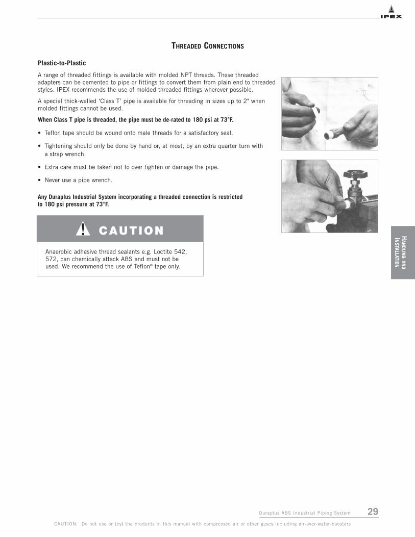
29Duraplus ABS Industrial Piping System
HAN
DLING
AND
INSTALLATION
THREADED CONNECTIONS
CAUTION: Do not use or test the products in this manual with compressed air or other gases including air-over-water-boosters
Plastic-to-Plastic
A range of threaded fittings is available with molded NPT threads. These threadedadapters can be cemented to pipe or fittings to convert them from plain end to threadedstyles. IPEX recommends the use of molded threaded fittings wherever possible.
A special thick-walled ‘Class T’ pipe is available for threading in sizes up to 2" whenmolded fittings cannot be used.
When Class T pipe is threaded, the pipe must be de-rated to 180 psi at 73°F.
• Teflon tape should be wound onto male threads for a satisfactory seal.
• Tightening should only be done by hand or, at most, by an extra quarter turn with a strap wrench.
• Extra care must be taken not to over tighten or damage the pipe.
• Never use a pipe wrench.
Any Duraplus Industrial System incorporating a threaded connection is restrictedto 180 psi pressure at 73°F.
CAUTION
Anaerobic adhesive thread sealants e.g. Loctite 542,572, can chemically attack ABS and must not beused. We recommend the use of Teflon® tape only.
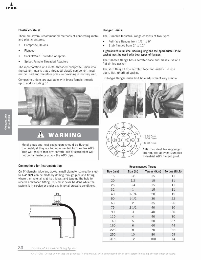
30 Duraplus ABS Industrial Piping System
HAN
DLIN
GAN
DIN
STAL
LATI
ON
CAUTION: Do not use or test the products in this manual with compressed air or other gases including air-over-water-boosters
Plastic-to-Metal
There are several recommended methods of connecting metaland plastic systems.
• Composite Unions
• Flanges
• Socket/Male Threaded Adapters
• Spigot/Female Threaded Adapters
The incorporation of a metal threaded composite union intothe system means that a threaded plastic component neednot be used and therefore pressure de-rating is not required.
Composite unions are available with brass female threadsup to and including 1".
Connections for Instrumentation
On 6" diameter pipe and above, small diameter connections upto 1/4" NPT can be made by drilling through pipe and fittingwhere the material is at its thickest and tapping the hole toreceive a threaded fitting. This must never be done while thesystem is in service or under any internal pressure conditions.
Flanged Joints
The Duraplus Industrial range consists of two types:
• Full-face flanges from 1/2" to 6" • Stub flanges from 2" to 12"
A galvanized mild steel backing ring and the appropriate EPDMgasket must be used with both types of flanges.
The full-face flange has a serrated face and makes use of aflat drilled gasket.
The stub flange has a serrated face and makes use of aplain, flat, undrilled gasket.
Stub-type flanges make bolt hole adjustment very simple.
4
1
3
2
4
1
3
8
6
5
7
2
4
1
3
8
10
9
7
25 12
11 6
4-Bolt Flange8-Bolt Flange
12-Bolt Flange
Note: Two steel backing ringsare required at every DuraplusIndustrial ABS flanged joint.
Size (mm) Size (in) Torque (N.m) Torque (lbf.ft)
16 3/8 15 11
20 1/2 15 11
25 3/4 15 11
32 1 15 11
40 1-1/4 20 15
50 1-1/2 30 22
63 2 35 26
75 2-1/2 40 30
90 3 40 30
110 4 40 30
140 5 50 37
160 6 60 44
225 8 70 52
250 10 80 59
315 12 100 74
Recommended Torque
Metal pipes and heat exchangers should be flushedthoroughly if they are to be connected to Duraplus ABS. This will ensure that any harmful oils or settlement willnot contaminate or attack the ABS pipe.
WARNING

31Duraplus ABS Industrial Piping System
HAN
DLING
AND
INSTALLATION
CAUTION: Do not use or test the products in this manual with compressed air or other gases including air-over-water-boosters
INSTALLATION OF BURIED PIPE
Recommendations covering essential requirements for largeinstallations below-ground can be summarized as follows:
Trenches
• In general, trenches should not be less than 3' deep. However, site conditions may permit pipe being laidnearer to the surface; contact IPEX for detailed advice.
• Trenches should be straight-sided and as narrow as is practical to allow proper consolidation of packaging materials.
• Trench bottoms should be as level as practical.
• Large pieces of rock, debris and sharp objects shouldbe removed.
• Unless the excavation is of friable, small and regular material, a bed of finely graded gravel should be laid approximately 3" deep on the floor of trench.(Sand may be used, but subterranean water is liableto wash sand away and leave the pipe unsupported.)
Installations
• If pipe is joined above-ground, it should remain undisturbed for 2 hours before being ‘snaked’ into the trench. Alternatively, it may be joined in the trench.
• Particular care should be taken to ensure pipe andjoining materials are dry and free of debris whenbeginning the joining procedure.
• After laying, pipe should be covered with pea gravel or similar material to a depth of 3" above the pipe and extended sideways to both trench walls and then compacted. The joint should be left exposed forpressure testing.
• Care should be taken to ensure that sharp objects,stones, etc., are prevented from falling into the trenchbefore covering the pipe with pea gravel.
• Backfilling should be carried out between joints prior to pressure testing.
• After pressure testing, joints should be covered with pea gravel and backfilling completed.
Thrust Blocks
For solvent welded systems thrust blocks are not required.
For mechanical joint systems, it is necessary to provideconcrete anchor blocks at all sudden changes in direction,such as elbows, bonds, trees etc. This is necessary towithstand the forces generated by system pressurization.
Note: Do not lay ABS in contaminated ground or wherechemical spilages may occur.
Installed Exposure to Sunlight
Where pipes are to be installed in locations likely to bepermanently exposed to prolonged periods of high-intensitysunlight, they can be protected from degradation by painting.
This precaution is not considered necessary for DuraplusIndustrial Pipe installed in the Northern States when carryinginnocuous liquids.
Where the full ductility of the Duraplus System needs to bemaintained, or where Duraplus Industrial systems are usedfor conveying hazardous liquids or compressed gases inexposed locations, it is recommended that they are paintedto retain the full toughness and ductility of the material.This can be achieved as follows:
1. Lightly abrade the pipe and fittings using medium-gradeglass paper, to provide a ‘key’ for the paint to adhere to.
2. Clean the system with soap and water to remove anyresidual grease or oil. Do not use solvents or detergents.
3. Select a white, water-based latex paint, preferably onescontaining titanium dioxide. Do not use cellulose orsolvent-based paints.
4. Apply an undercoat followed by a final gloss coat.
A section of a pipe installed below-ground in accordance with thefollowing recommendations.
Below-Ground Installation

32 Duraplus ABS Industrial Piping System
HAN
DLIN
GAN
DIN
STAL
LATI
ON
CAUTION: Do not use or test the products in this manual with compressed air or other gases including air-over-water-boosters
TESTING STORAGE
Site Pressure Testing
The purpose of an onsite pressure test is to establish that theinstalled section of line – and in particular all joints andfittings – will withstand the design working pressure, plus asafety margin, without loss of pressure or fluid.
Generally a test pressure of 1-1/2 times the safe workingpressure for the installed pipe is adequate. Wheneverpossible, it is recommended that hydrostatic testing becarried out. It is suggested that the following hydrostatic testprocedure be followed after the solvent-welded joints havebeen allowed to cure for a minimum period of 24 hours at73°F (timed from the last joint). Please refer to Joint CurveSchedule for details (page 25).
Hydrostatic Test Procedure
1. Fully inspect the installed piping for evidence ofmechanical abuse and/or dry, suspect joints.
2. Split the system into convenient test sections notexceeding 1,000 ft.
3. Slowly fill the pipe section with cold water, taking careto evacuate all entrapped air in the process. Use airrelease valves at any high points in the system. Do notpressurize at this stage.
4. Leave the section for at least 1 hour to allow equilibriumtemperature to be achieved.
5. Check the system for leaks. If clear, check for andremove any remaining air and increase pressure up to50 psi. Do not pressurize further at this stage.
6. Leave the section pressurized for 10 minutes. If thepressure decays, inspect for leaks. If the pressureremains constant, slowly increase the hydrostaticpressure to 1-1/2 times the nominal working pressure.
7. Leave the section pressurized for a period not exceeding1 hour. During this time, the pressure should not change.
If there is a significant drop in static pressure or extendedtimes are required to achieve pressure, either joint leakagehas occurred or air remains in the line. Inspect for leakageand if none is apparent, reduce the pressure and check for trapped air. This must be removed before further testing.
Any joint leaks should be repaired and allowed to cure fullybefore re-pressurizing for a minimum of 24 hours.
Prolonged Storage in Sunlight
Prolonged storage in sunlight may lead to degradation andsome loss of impact resistance because of the combinedeffect of heat and ultraviolet radiation. Tarps should be usedwherever possible to prevent this from happening.
On-site Storage
The high-impact strength of the Duraplus Industrial Systemprovides some protection against damage to plastic pipe oftenincurred during handling and storage on-site.
However, it is recommended the following precautions aretaken:
1. The storage site should be flat, level and free from sharpstones, etc.
2. Pipes should not be stacked to heights exceeding thefollowing:
3. Smaller pipes may be ‘nested’ inside larger pipes.
4. Side bracing should be provided to prevent stackcollapse.
Pipe Size Max Stacking Height
up to 3" 20 x pipe size
4" to 6" 12 x pipe size
8" 7 x pipe size
10" 4 x pipe size
12" 4 x pipe size

33Duraplus ABS Industrial Piping System
HAN
DLING
AND
INSTALLATION
CAUTION: Do not use or test the products in this manual with compressed air or other gases including air-over-water-boosters
Freezing Conditions
Precautions should be taken to prevent contentsfrom freezing, as this can cause pipe work to split.Glycol can be added to the system to lower thefreezing point.
Thermal Insulation
Some insulation products can contain substances capableof having a detrimental effect on thermoplastic pipe work(eg. certain types of foam rubber insulations can causepipes to fail where the ABS is conveying liquids attemperatures above 86OF (30OC.) Common insulationmaterials known to be suitable with ABS pipe work are:
• fiber wool, such as 'Rockwool'• Armaflex Class 1 HT• Koolphen K Phenolic foam• Polystyrene
Note: Please contact our Technical Customer Serviceif further assistance or recommendations are required.
Some adhesives can be detrimental. Do not bondinsulation to ABS. (This comment also applies to anytapes, adhesives, or other substances used to secure theheating tape to the pipe work.)
Trace Heating
The selection of heating tapes with silicone rubber, wovenwire, or woven polyester outer sheaths will eliminate therisk of plasticizer migration. These tapes are thereforepreferred for use on thermoplastic systems.
Pipe Contents Identification
Do not put self-adhesive labels directly on to pipesurfacesas this may be detrimental to pipe performance. It isrecommended that some sort of barrier, such as aluminumfoil, is placed between pipe and identification label.
Sealants
Certain sealants are formulated with phthalates.Phthalates are known to be extremely aggressive towardABS materials, and therefore confirmation of thesuitability of any mastic sealant should be determinedbefore being used in conjunction with ABS pipe work.IPEX USA, LLC recommends using Teflon tape.
Contact with Synthetic oils
Some synthetic oils used for drawing tubes and tubebending in the production of equipment such as fan coils,refrigeration display cases and other metal coiled devicesare unsuitable for use with thermoplastic piping systems.The main types of synthetic oils identified as beingincompatible with thermoplastic piping systems includebut are not limited to Esters, Polyalkylene Glycols, andOrganic Phosphates.
Some metal equipment manufacturers use these oils intheir manufacturing process and normally remove theseoils after manufacturing the part. However, IPEXrecommends flushing the metal equipment thoroughlybefore installation with the thermoplastic piping system toensure that residual oil left in the equipment cannot comeinto contact with the ABS.
IPEX USA, LLC recommends flushing the equipment withmethylated spirits, however the equipment manufacturershould always be contacted for compatibility andcomplete flushing procedures. It is important to ensureproper drying time after flushing before connecting theequipment to the ABS piping system. Please note thatonly the metal pipe in the equipment should be flushed,ABS piping should not be flushed with methylated spirits.
Contact with Fluxes
Some fluxes can be detrimental to ABS. Care should betaken when soldering copper pipe work directly above,or close to, ABS pipe work.
Pressure Surges
Pressure surges should not be allowed to exceed themaximum continuous working pressure of the system.
Insulation
Some insulation products may be unsuitable for use withDuraplus ABS Industiral piping systems. They maycontain harmful plasticizers which can migrate into theABS material. Certain insulation products are suitable foruse with ABS but may need to be installed usingadhesives that contain harmful solvents.
It is important to ensure compatibility of the insulationmaterial as well as installation materials, such asadhesives, with your IPEX representative.
WARNING
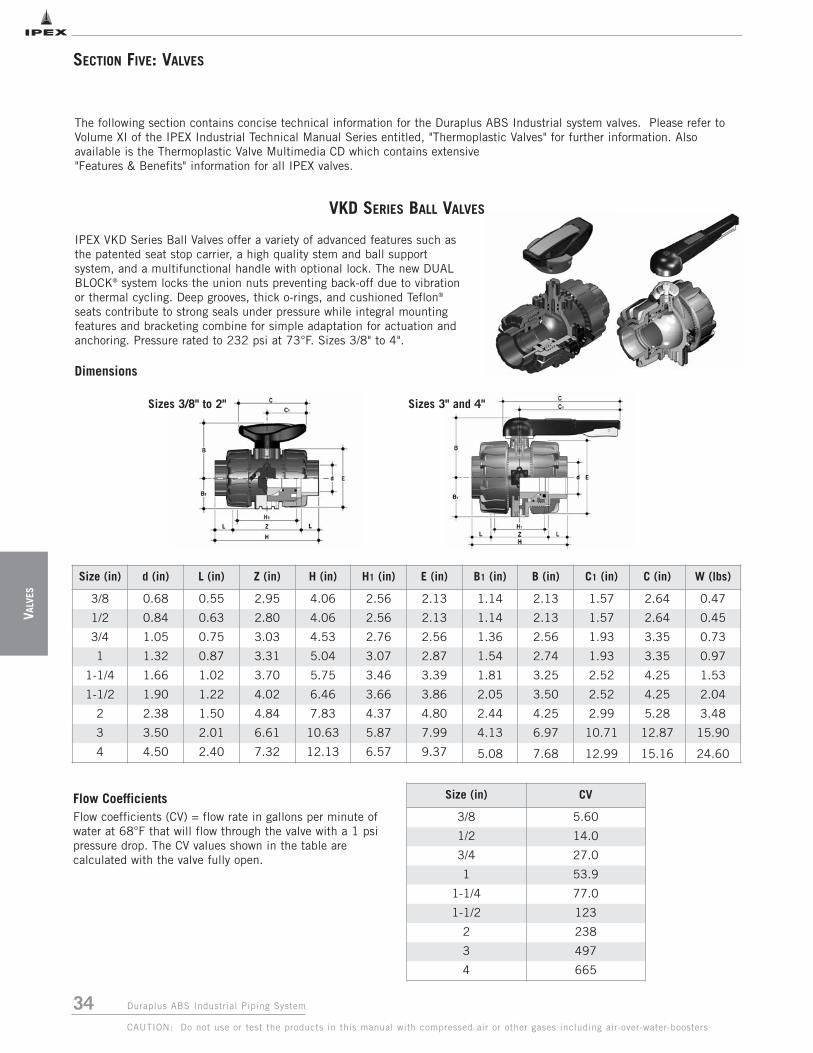
34 Duraplus ABS Industrial Piping System
VALV
ES
CAUTION: Do not use or test the products in this manual with compressed air or other gases including air-over-water-boosters
SECTION FIVE: VALVES
Size (in) d (in) L (in) Z (in) H (in) H1 (in) E (in) B1 (in) B (in) C1 (in) C (in) W (lbs)
3/8 0.68 0.55 2.95 4.06 2.56 2.13 1.14 2.13 1.57 2.64 0.47
1/2 0.84 0.63 2.80 4.06 2.56 2.13 1.14 2.13 1.57 2.64 0.45
3/4 1.05 0.75 3.03 4.53 2.76 2.56 1.36 2.56 1.93 3.35 0.73
1 1.32 0.87 3.31 5.04 3.07 2.87 1.54 2.74 1.93 3.35 0.97
1-1/4 1.66 1.02 3.70 5.75 3.46 3.39 1.81 3.25 2.52 4.25 1.53
1-1/2 1.90 1.22 4.02 6.46 3.66 3.86 2.05 3.50 2.52 4.25 2.04
2 2.38 1.50 4.84 7.83 4.37 4.80 2.44 4.25 2.99 5.28 3.48
3 3.50 2.01 6.61 10.63 5.87 7.99 4.13 6.97 10.71 12.87 15.90
4 4.50 2.40 7.32 12.13 6.57 9.37 5.08 7.68 12.99 15.16 24.60
Sizes 3" and 4"Sizes 3/8" to 2"
Size (in) CV
3/8 5.60
1/2 14.0
3/4 27.0
1 53.9
1-1/4 77.0
1-1/2 123
2 238
3 497
4 665
Flow CoefficientsFlow coefficients (CV) = flow rate in gallons per minute ofwater at 68°F that will flow through the valve with a 1 psipressure drop. The CV values shown in the table arecalculated with the valve fully open.
The following section contains concise technical information for the Duraplus ABS Industrial system valves. Please refer toVolume XI of the IPEX Industrial Technical Manual Series entitled, "Thermoplastic Valves" for further information. Alsoavailable is the Thermoplastic Valve Multimedia CD which contains extensive"Features & Benefits" information for all IPEX valves.
IPEX VKD Series Ball Valves offer a variety of advanced features such asthe patented seat stop carrier, a high quality stem and ball supportsystem, and a multifunctional handle with optional lock. The new DUALBLOCK® system locks the union nuts preventing back-off due to vibrationor thermal cycling. Deep grooves, thick o-rings, and cushioned Teflon®
seats contribute to strong seals under pressure while integral mountingfeatures and bracketing combine for simple adaptation for actuation andanchoring. Pressure rated to 232 psi at 73°F. Sizes 3/8" to 4".
Dimensions
VKD SERIES BALL VALVES

35Duraplus ABS Industrial Piping System
VALVES
CAUTION: Do not use or test the products in this manual with compressed air or other gases including air-over-water-boosters
VKD SERIES BALL VALVES CON’T
Components
# Component Material
1 Insert PVC2 Handle PVC3 Stem O-Ring EPDM4 Stem Duraplus ABS5 Ball Seat PTFE6 Ball Duraplus ABS7 Body Duraplus ABS8 Ball Seat O-Ring EPDM9 Body O-Ring EPDM
10 Socket O-Ring EPDM11 Carrier with Stop Ring Duraplus ABS12 End Connector Duraplus ABS13 Union Nut Duraplus ABS16 Dual Block® POM
# Component Material
1 Protective Cap PE2 Handle PVC3 Bolt SS4 Washer SS5 Ball Seat PTFE6 Ball Duraplus ABS7 Body Duraplus ABS8 Ball Seat O-ring EPDM9 Body O-Ring EPDM
10 Socket O-Ring EPDM11 Bolt SS12 End Connector Duraplus ABS13 Union Nut Duraplus ABS14 Washer SS15 Nut SS16 Carrier Duraplus ABS17 Stop Ring Duraplus ABS18 Stem O-Ring EPDM19 Bushing PTFE20 Upper Stem Duraplus ABS & SS21 Lower Stem Duraplus ABS22 Pad GRPP23 Protective Cap PE24 Spring SS25 Nut Block GRPP26 Cover PP27 Nut Block Button GRPP28 Protective Cap PE29 Screw Nylon
Sizes 3" and 4"
Sizes 3/8" to 2"

36 Duraplus ABS Industrial Piping System
VALV
ES
CAUTION: Do not use or test the products in this manual with compressed air or other gases including air-over-water-boosters
VKD SERIES BALL VALVES CON’T
Sample Specification
1.0 Ball Valves – VKD
1.1 Material
• The valve body, stem, ball and unions shall be made ofDuraplusTM ABS compound which shall meet or exceedthe requirements of cell classification 43234 accordingto ASTM D3965.
1.2 Seats
• The ball seats shall be made of Teflon® (PTFE).
1.3 Seals
• The o-ring seals shall be made of EPDM.
2.0 Connections
2.1 Socket style
• The socket end connections shall conform to DuraplusTM
ABS pipe dimensions as manufactured by IPEX.
3.0 Design Features
• The valve shall be double blocking with union ends.
• All valves shall be full port.
• All valves shall allow for bi-directional flow.
• The valve body shall be single end entry with a threadedcarrier (ball seat support).
• The threaded carrier shall be adjustable with the valveinstalled.
• The valve body shall have an expansion and contractioncompensating groove on the molded end.
• The valve body, union nuts, and carrier shall have deep square style threads for increased strength.
• The ball shall be machined smooth to minimize wearon valve seats.
• All valve seats shall have o-ring backing cushions to compensate for wear and prevent seizure of the ball.
• The stem design shall feature double o-ring seals as wellas a safety shear point above the o-rings.
• All valves shall have integrally molded mounting featuresfor actuation.
• All valves shall have integrally molded supportbracketing for anchoring.
• The valve shall include the Dual Block® union nutlocking mechanism.
3.1 Pressure Tested
• All valves shall have been pressure tested in both theopen and closed positions by the manufacturer.
3.2 Pressure Rating
• All valves shall be rated at 232 psi at 73ºF.
3.3 Markings
• All valves shall be marked to indicate size, material designation, and manufacturers name or trade mark.
3.4 Color Coding
• All valves shall be color-coded light gray.
4.0 All valves shall be Duraplus® ABS by IPEX orapproved equal.
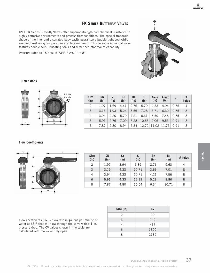
37Duraplus ABS Industrial Piping System
VALVES
CAUTION: Do not use or test the products in this manual with compressed air or other gases including air-over-water-boosters
IPEX FK Series Butterfly Valves offer superior strength and chemical resistance inhighly corrosive environments and process flow conditions. The special trapezoidshape of the liner and a serrated body cavity guarantee a bubble tight seal whilekeeping break-away torque at an absolute minimum. This versatile industrial valvefeatures double self-lubricating seals and direct actuator mount capability.
Pressure rated to 150 psi at 73°F. Sizes 2" to 8"
Size (in)
DN (in)
Z (in)
B1
(in)B2
(in)H
(in)Amin(in)
Amax(in) f
# holes
2 1.97 1.69 4.41 2.76 5.79 4.53 4.94 0.75 4
3 3.15 1.93 5.24 3.66 7.28 5.71 6.30 0.75 8
4 3.94 2.20 5.79 4.21 8.31 6.50 7.48 0.75 8
6 5.91 2.76 7.09 5.28 10.55 9.06 9.53 0.91 8
8 7.87 2.80 8.94 6.34 12.72 11.02 11.73 0.91 8
Size (in)
DN (in)
C1
(in)C
(in)B2
(in)B3
(in)# holes
2 1.97 3.94 6.89 2.76 5.63 4
3 3.15 4.33 10.71 3.66 7.01 8
4 3.94 4.33 10.71 4.21 7.56 8
6 5.91 4.33 12.99 5.28 8.86 8
8 7.87 4.80 16.54 6.34 10.71 8
Flow Coefficients
Size (in) CV
2 90
3 249
4 413
6 1309
8 2135
Flow coefficients (CV) = flow rate in gallons per minute ofwater at 68OF that will flow through the valve with a 1 psipressure drop. The CV values shown in the table arecalculated with the valve fully open.
FK SERIES BUTTERFLY VALVES
Dimensions

38 Duraplus ABS Industrial Piping System
VALV
ES
CAUTION: Do not use or test the products in this manual with compressed air or other gases including air-over-water-boosters
FK SERIES BUTTERFLY VALVES CON’T
Sizes 3" to 8"Sizes 2"
# Component Material
15 Bushing O-Ring EPDM
16 Bushing nylon
17 Shaft O-Ring EPDM
18 Shaft O-Ring EPDM
19 Body GRPP
20 Cap PE
21 Wcrew SS
22 Washer SS
23 Anti-Friction Ring PTFE
24 Disc O-Ring EPDM
25 Disc Duraplus ABS
26 Primary Liner EPDM
27 Inserts ABS
28 Cap PE
# Component Material
1 Handle Insert ABS
2 Handle PVC
3 Cap PE
4 Screw SS
5 Washer SS
6 Spacer Pad GRPP
7 Screw SS
8 Screw SS
9 Ratchet SS
10 Pad GRPP
11 Washer SS
12 Nut SS
13 Retaining Ring SS
14 Shaft 420 SS
Components

39Duraplus ABS Industrial Piping System
VALVES
CAUTION: Do not use or test the products in this manual with compressed air or other gases including air-over-water-boosters
FK SERIES BUTTERFLY VALVES CON’T
Sample Specification
1.0 Material
• The valve body shall be made of glass reinforcedpolypropylene (GRPP) obtained from homopolymerpolypropylene (PPH).
• The valve disc shall be made of DuraplusTM ABScompound which shall meet or exceed the requirementsof cell classification 43234 according to ASTM D3965.
• The valve shaft shall be made of 420 stainless steel.
1.2 Seats
• The disc liner shall be made of EPDM.
1.3 Seals
• The o-ring seals shall be made of EPDM.
2.0 Connections
2.1 Flanged style
• The ANSI 150 flanged connections shall conform to thedimensional standard ANSI B16.5.
3.0 Design Features
• The valve shall be of wafer design.
• Manual control of the valve shall be achieved throughthe use of a lever handle.
• The shaft shall have standard ISO square dimensions fordirect mounting of actuators.
• The disc shall be a trapezoidal elastomeric liner andprovide a bubble tight seal.
• The liner shall completely isolate the valve body fromthe process flow.
• The liner shall function as a flange gasket on both sidesof the valve.
• The body cavity shall feature special channeling toprevent liner slippage and compression.
• The disc, seats, and seals shall be the only wetted parts.
• Teflon® seated o-ring seals shall prevent the stainlesssteel shaft from becoming wetted.
3.1 Pressure Rating
• All valves shall be rated at 150 psi at 73OF.
3.2 Markings
• All valves shall be marked to indicate size, materialdesignation, and manufacturers name or trade mark.
3.3 Color Coding
• All valves shall be color-coded light gray.
4.0 All valves shall be DuraplusTM ABS by IPEX orapproved equal.

40 Duraplus ABS Industrial Piping System
VALV
ES
CAUTION: Do not use or test the products in this manual with compressed air or other gases including air-over-water-boosters
VM SERIES DIAPHRAGM VALVES
IPEX VM Series Diaphragm Valves are the ideal solution for modulatingflow and precise throttling in a variety of applications. The compactmodular design allows for installation in any orientation, simpleelastomer replacement, and possible conversion to an automated valvewithout removing the body from the line. Pressure rated to 150 psi at73°F. Sizes 1/2" to 3".
Dimensions
Flow CoefficientsSize (in) CV
1/2 6.51
3/4 9.52
1 12.3
1-1/4 21.0
1-1/2 29.1
2 53.6
3 140
Flow coefficients (CV) = flow rate in gallons per minute ofwater at 68°F that will flow through the valve with a 1 psipressure drop. The CV values shown in the table arecalculated with the valve fully open.
Components
# Component Material
1 Handwheel GFPP
2 Bonnet GFPP
3 Compression Bearing POM
4 Security Ring brass
5 Indicator - Stem SS
6 Compressor PBT
7 Pin SS
8 Diaphragm EPDM
9 Valve Body Duraplus ABS
10 Washer zinc plated steel
11 Hex Bolt zinc plated steel
12 Protective Cap PE
Note: Other diaphragm materials available upon request* 3" and 4" are spigot ended
Nom. PipeSize
Critical Dimensions (inches)
d H L B1 B H1 h JWt.(lbs)
1/2 0.84 4.88 0.63 1.02 3.74 3.54 0.47 M6 1.54
3/4 1.05 5.67 0.75 1.02 3.74 3.54 0.47 M6 1.54
1 1.32 6.06 0.91 1.02 3.74 3.54 0.47 M6 1.54
1-1/4 1.66 6.85 1.06 1.57 4.96 4.53 0.71 M8 3.31
1-1/2 1.90 7.64 1.26 1.57 4.96 4.53 0.71 M8 3.31
2 2.38 8.82 1.54 1.57 5.83 5.51 0.71 M8 5.29
* 3 3.50 11.81 2.01 2.17 8.86 8.46 0.91 M12 15.43
* 4 4.50 13.78 – 2.72 11.61 9.84 0.91 M12 23.15

41Duraplus ABS Industrial Piping System
VALVES
CAUTION: Do not use or test the products in this manual with compressed air or other gases including air-over-water-boosters
VM SERIES DIAPHRAGM VALVES CON’T
Sample Specification
1.0 Diaphragm Valves – VM
1.1 Material
• The valve body, stem, ball and unions shall be made ofDuraplusTM ABS compound which shall meet or exceedthe requirements of cell classification 43234 accordingto ASTM D3965.
• The valve bonnet assembly shall be made of hightemperature, high strength, glass-filled polypropylene.
1.2 Diaphragm
• The diaphragm shall be made of EPDM.
2.0 Connections
2.1 Spigot style
• The spigot end connections shall conform to DuraplusTM
ABS pipe dimensions as manufactured by IPEX.
3.0 Design Features
• All valves shall be weir-style for throttling applications.
• All bodies to be used with EPDM diaphragms shallfeature raised molded sealing rings (concentric).
• All through bolts shall be made of 304 stainless steel.
• All manual valves shall have a rising position indicator.
3.1 Pressure Rating
• All valves shall be rated at 150 psi at 73OF.
3.2 Markings
• All valves shall be marked to indicate size, materialdesignation, and manufacturers name or trade mark.
3.3 Color Coding
• All valves shall be color-coded light gray.
• All bonnet assemblies shall be color-coded red.
4.0 All valves shall be DuraplusTM ABS by IPEX orapproved equal.

42 Duraplus ABS Industrial Piping System
VALV
ES
CAUTION: Do not use or test the products in this manual with compressed air or other gases including air-over-water-boosters
SINGLE UNION BALL CHECK VALVES
Size (in)
d (in)
Z (in)
A (in)
B (in)
W(lbs)
3/8 0.68 2.44 1.89 3.74 0.24
1/2 0.84 2.44 1.89 3.74 0.22
3/4 1.05 2.87 2.32 4.41 0.36
1 1.32 3.11 2.72 4.88 0.55
1-1/4 1.66 3.70 3.78 5.83 1.34
1-1/2 1.90 3.46 3.78 5.83 1.27
2 2.38 4.13 4.06 6.97 1.76
3 3.50 4.49 7.01 8.46 6.08
Sample Specification
1.0 Ball Check Valves
1.1. Material
• The valve body, ball, and union shall be made ofDuraplusTM ABS compound which shall meet or exceedthe requirements of cell classification 43234 accordingto ASTM D3965.
1.2. Seals
• The gasket and o-ring seal shall be made of EPDM.
2.0 Connections
2.1. Socket style
• The socket end connections shall conform toDuraplusTM ABS pipe dimensions as manufacturedby IPEX.
3.0 Design Features
• The valve shall have a single union design to allow forin-line maintenance.
• The valve body shall be single end entry.
• The valve body shall have guide ribs to allow formaximum flow and minimum turbulence, to preventball sticking and chatter.
• The valve shall provide positive shut off in both verticaland horizontal orientations.
3.1. Pressure Rating
• All valves shall be rated at 150 psi at 73ºF.
3.2. Markings
• All valves shall be marked to indicate size, materialdesignation, and manufacturers name or trade mark.
3.3. Color Coding
• All valves shall be color-coded light gray.
4.0 All valves shall be DuraplusTM ABS by IPEXor approved equal.
IPEX Single Union Ball Check Valves provide a simple solution forpreventing backflow in a Duraplus ABS piping system. The single uniondesign allows easy dismantling of the system for in-line maintenancewhile guide ribs allow for maximum flow and minimum turbulence,preventing ball sticking and chatter. Just a few psi of back pressure isneeded for positive shut off in both vertical and horizontal orientations.Pressure rated to 150 psi at 73ºF.Sizes 3/8" to 3".
Dimensions

43Duraplus ABS Industrial Piping System
VALVES
CAUTION: Do not use or test the products in this manual with compressed air or other gases including air-over-water-boosters
RV SERIES SEDIMENT STRAINERS
IPEX RV Series Sediment Strainers protect critical pipelinecomponents by removing solids and suspended impurities.The bottom-entry design permits in-line maintenance andsimple cleaning or replacement of worn screens. True unionends facilitate both installation and removal. Pressure ratedto 220 psi at 73ºF depending on size. Sizes 1/2" to 2".
Dimensions
Size (in)
d (in)
L (in)
Z(in)
H (in)
E (in)
B(in)
Amax(in)
1/2 0.84 0.63 4.06 5.31 2.17 2.83 4.92
3/4 1.05 0.75 4.72 6.22 2.60 3.31 5.71
1 1.32 0.87 5.20 6.93 2.95 3.74 6.50
1-1/4 1.66 1.02 6.10 8.15 3.43 4.37 7.48
1-1/2 1.90 1.22 7.13 9.57 3.94 4.72 8.27
2 2.38 1.50 8.72 11.73 4.72 5.47 9.45
Flow Coefficients
Components
Size (in) CV
1/2 2.80
3/4 4.90
1 7.21
1-1/4 13.2
1-1/2 17.9
2 28.7
Flow coefficients (CV) = flow rate in gallons per minute ofwater at 68ºF that will flow through the valve with a 1 psipressure drop. The CV values shown in the table arecalculated with the valve fully open.
# Component Material
1 Body Duraplus ABS
2 Screen Mesh PP
3 Bonnet Duraplus ABS
4 Screen Support Duraplus ABS
5 O-Ring Seal EPDM
6 Retaining Ring Duraplus ABS
7 Lock Nut Duraplus ABS
8 Split Ring Duraplus ABS
9 Socket O-Ring EPDM
10 End Connector Duraplus ABS
11 Union Nut Duraplus ABS
Sizes 1/2" to 2"

44 Duraplus ABS Industrial Piping System
VALV
ES
CAUTION: Do not use or test the products in this manual with compressed air or other gases including air-over-water-boosters
RV SERIES SEDIMENT STRAINERS CON’T
Sample Specification
1.0 Sediment Strainers – RV
1.1. Material
• The valve body, end connectors, and unions shall bemade of DuraplusTM ABS compound which shall meet orexceed the requirements of cell classification 43234according to ASTM D3965.
1.2. Seals
• The o-ring seals shall be made of EPDM.
1.3. Mesh Screen
• The mesh screen shall be made of PP which shall meetor exceed the requirements of Type 1 Polypropyleneaccording to ASTM D4101.
2.0 Connections
2.1. Socket style
• The socket end connections shall conform toDuraplusTM ABS pipe dimensions as manufacturedby IPEX.
3.0 Design Features
• Strainers shall be Y-pattern in style.
• All sizes shall have true union ends.
• It shall be possible to service the valve without removingit from the line.
• The filter screen shall be size ASTM 30 mesh.
3.1. Pressure Rating
• Strainer sizes 1/2" through 1-1/2" shall be rated at220 psi at 73ºF.
• Strainer size 2" shall be rated at 130 psi at 73ºF.
3.2. Markings
• All valves shall be marked to indicate size, materialdesignation, and manufacturers name or trade mark.
3.3. Color Coding
• All valves shall be color-coded light gray.
4.0 All valves shall be DuraplusTM ABS by IPEX or approved equal.

45Duraplus ABS Industrial Piping System
CAUTION: Do not use or test the products in this manual with compressed air or other gases including air-over-water-boosters
This page intentionally
left blank

46 Duraplus ABS Industrial Piping System
DIM
ENSI
ONAL
DATA
CAUTION: Do not use or test the products in this manual with compressed air or other gases including air-over-water-boosters
SECTION SIX: DIMENSIONAL DATA
Pipe – 90 psi at 73ºF (Class B)
Pipe – 145 psi at 73ºF (Class C)
Pipe – 180 psi at 73ºF (Class D)
A
t
PipeDiameter (D)
SignificantNumber
ProductCode
Critical Dimensions
A t (min) StandardLength (ft) lb./ft.
10 542114 346034 10.75 0.423 20 6.77
12 542115 346035 12.75 0.501 20 9.52
PipeDiameter (D)
SignificantNumber
ProductCode
Critical Dimensions
A t (min) StandardLength (ft) lb./ft.
1 511104 346003 1.315 0.082 20 0.15
1-1/2 511106 346004 1.900 0.118 20 0.33
2 511107 346005 2.375 0.147 20 0.51
3 511109 346007 3.500 0.216 20 1.10
4 511110 346008 4.500 0.278 20 1.82
6 511112 346009 6.625 0.410 20 3.94
8 511513 346010 8.625 0.533 20 6.67
PipeDiameter (D)
SignificantNumber
ProductCode
Critical Dimensions
A t (min) StandardLength (ft) lb./ft.
6 512112 346012 6.625 0.501 20 4.74
Note: Duraplus ABS fabricated fittings are custom made from pipe and FRP wrapped for rigidity and improved pressurecapability. Due to manufacturing constraints, some fittings may not be exactly symmetrical or appear as sketched. Thedimensions provided are approximate and should not be used to create precise layouts.
* Fabricated spigot end fittings are rated at 73oF for: 3" to 8" (100psi); 10" & 12" (90psi)
A
t
A
t
PipeDiameter (D)
SignificantNumber
ProductCode
Critical Dimensions
A t (min) StandardLength (ft) lb./ft.
3/8 513101 346018 0.675 0.070 10 0.06
1/2 513102 346019 0.84 0.088 10 0.09
3/4 513103 346020 1.05 0.100 20 0.15
1 513104 346021 1.315 0.125 20 0.23
1-1/4 513105 346022 1.66 0.157 20 0.37
1-1/2 513106 346023 1.90 0.180 20 0.48
2 513107 346024 2.375 0.225 20 0.75
3 513109 346025 3.50 0.331 20 1.62
4 513110 346026 4.50 0.426 20 2.68
Pipe – 230 psi at 73ºF (Class E)
A
t

47Duraplus ABS Industrial Piping System
DIM
ENSION
ALD
ATA
CAUTION: Do not use or test the products in this manual with compressed air or other gases including air-over-water-boosters
DIMENSIONS CON’T
* Clips of size 1-1/4" and above are fitted with retaining strap. Bolts/screws not supplied.
A
G B
C
Nom. PipeSize
SignificantNo.
ProductCode
Critical Dimensions
A B C GScrew/
Bolt SizeWt. (oz)
3/8 434305 437340 - 1.38 0.98 0.63 #8 5/32" 0.25
1/2 434306 437341 - 1.38 1.18 0.63 #10 1/4" 0.29
3/4 434307 437342 - 1.38 1.38 0.67 #10 1/4" 0.39
1 434308 437343 - 1.57 1.57 0.67 #10 1/4" 0.49
*1-1/4 434309 437344 2.95 1.77 1.77 0.79 #10 1/4" 0.74
*1-1/2 434310 437345 3.35 1.97 1.97 0.83 #10 1/4" 1.05
*2 434311 437346 4.02 2.36 2.36 0.83 #10 1/4" 1.47
*3 434313 437348 5.83 3.15 3.54 1.22 5/16" 4.26
*4 434314 437349 6.73 3.54 3.78 1.38 5/16" 6.53
6 434317 437432 9.57 6.69 5.91 1.57 5/16" 11.64
Cobra Clip – Polypropylene
Class “T” – Suitable for Threading
PipeDiameter (D)
SignificantNumber
ProductCode
Critical Dimensions
A t (min)Standard
Length (ft)lb./ft.
3/8 514101 346003 0.675 0.133 10 0.11
1/2 514102 346027 0.84 0.137 10 0.14
3/4 514103 346028 1.05 0.137 20 0.19
1 514104 346029 1.315 0.165 20 0.29
1-1/4 514105 346030 1.66 0.200 20 0.44
1-1/2 514106 346031 1.90 0.228 20 0.57
2 514107 346032 2.375 0.275 20 0.86
Saddle Clip – Polypropylene
D
C
A
Nom. PipeSize
SignificantNo.
ProductCode
Critical Dimensions
A C DScrew/
Bolt SizeWt. (oz)
3/8 455101 337453 1.46 0.51 0.56 #8 5/32" 0.11
1/2 455102 337454 1.61 0.71 0.55 #8 5/32" 0.14
3/4 455103 337455 1.77 0.83 0.63 #10 1/4" 0.21
1 455104 337456 2.20 0.91 0.63 #10 1/4" 0.25
1-1/4 455105 337457 2.56 1.14 0.63 #10 1/4" 0.39
1-1/2 455106 337458 2.64 1.34 0.63 5/16" 0.42
2 455107 337459 3.43 1.50 0.87 5/16" 0.88
3 455109 337460 4.80 1.97 1.34 5/16" 1.59
4 455110 337461 6.14 2.56 1.50 - -
A
t

48 Duraplus ABS Industrial Piping System
DIM
ENSI
ONAL
DATA
CAUTION: Do not use or test the products in this manual with compressed air or other gases including air-over-water-boosters
DIMENSIONS CON’T
Nom. PipeSize
SignificantNo.
ProductCode
Critical Dimensions
Z1 A B Wt. (oz)
3/8 100101 337021 0.08 0.83 1.26 0.14
1/2 100102 337022 0.08 1.02 1.50 0.21
3/4 100103 337023 0.12 1.26 1.69 0.42
1 100104 337024 0.12 1.61 1.97 0.85
1-1/4 100105 337025 0.16 2.05 2.36 1.45
1-1/2 100106 337026 0.08 2.36 2.60 2.19
2 100107 337027 0.16 2.91 3.07 4.02
3 100109 337028 0.16 4.25 4.09 12.52
4 100110 337029 0.20 5.35 5.31 20.98
6 100112 337030 0.35 7.91 7.52 80.01
8 100113 337031 0.43 10.12 9.80 129.35
10 100114 337032 0.50 11.75 12.50 112.00
12 100115 337033 0.50 13.75 14.50 160.00
Coupling – Socket
B
A
z1
Nom. PipeSize
Significant No. Product CodeCritical Dimensions
Z1 B C D Wt. (oz)
1/2 129102 337226 0.16 3.78 0.83 0.39 2.65
3/4 129103 337227 0.16 4.13 0.94 0.39 3.00
1 129104 337228 0.16 4.53 1.06 0.39 3.92
1-1/4 129105 337229 0.16 5.51 1.26 0.39 4.59
1-1/2 129106 337330 0.20 5.91 1.42 0.39 5.64
2 129107 337231 0.24 6.50 1.77 0.43 8.22
3 129109 337232 0.31 7.83 2.36 0.43 14.60
4 129110 337233 0.24 8.66 2.87 0.55 23.18
6 129112 337234 0.31 11.18 3.90 0.87 49.98
Flange, Full-Face – Undrilled/Socket
D
B
C
z1

49Duraplus ABS Industrial Piping System
DIM
ENSION
ALD
ATA
CAUTION: Do not use or test the products in this manual with compressed air or other gases including air-over-water-boosters
DIMENSIONS CON’T
Flange, Stub – Socket
DB
A
z1
* These flanges have sloping shoulders. Backing rings are machined to match.
Nom.PipeSize
SignificantNo.
ProductCode
Critical Dimensions
Z1 B A D Wt. (oz)
2 135107 337235 0.12 1.57 3.78 0.55 3.17
3 135109 337236 0.24 2.24 5.00 0.71 7.05
4 135110 337237 0.24 2.72 6.26 0.79 12.35
6 135112 337238 0.43 4.09 8.39 0.94 28.40
8 135113 337239 0.55 5.20 10.59 1.02 73.20
*10 135114 337243 0.31 6.22 12.03 1.14 93.50
*12 135115 337244 0.39 7.09 14.27 1.34 137.57
Nom. PipeSize
SignificantNo.
ProductCode
Critical Dimensions
Z1 B C D E L Holes Wt. (oz)
1/2 322102 337353 0.16 3.78 0.83 0.39 2.36 0.55 4 2.40
3/4 322103 337354 0.16 4.13 0.94 0.39 2.76 0.55 4 2.75
1 322104 337355 0.16 4.53 1.06 0.39 3.15 0.55 4 3.77
1-1/4 322105 337356 0.16 5.51 1.30 0.39 3.50 0.625 4 4.30
1-1/2 322106 337357 0.206 5.91 1.46 0.39 3.86 0.55 4 5.43
2 322107 337358 0.24 6.54 1.77 0.39 4.76 0.71 4 7.87
3 322109 337359 0.31 7.83 2.36 0.43 5.98 0.71 4 14.04
4 322110 337360 0.24 8.66 2.83 0.55 7.48 0.71 8 22.50
6 322112 337361 0.31 11.18 3.86 0.87 9.49 0.875 8 47.27
Flange, Full-face – Drilled ANSI 150, Socket
C
E B
D
L DIA
z1

50
DIM
ENSI
ONAL
DATA
CAUTION: Do not use or test the products in this manual with compressed air or other gases including air-over-water-boosters
* These backing rings are machined to match the sloping shoulder of 10" and 12" stub flanges.
DIMENSIONS CON’T
D
B
L DIA
A
Gasket, Full-face – EPDM, Drilled to ANSI 150
Nom. PipeSize
SignificantNo.
ProductCode
Critical Dimensions
A B D L Holes Wt. (oz)
1/2 426102 337439 3.74 2.36 0.12 0.55 4 1.09
3/4 426103 337440 4.41 2.76 0.12 0.55 4 1.31
1 426104 337441 4.53 3.15 0.12 0.55 4 1.31
1-1/4 426105 337442 4.75 3.50 0.12 0.625 4 1.45
1-1/2 426106 337443 5.24 3.86 0.12 0.55 4 1.94
2 426107 337444 6.02 4.76 0.12 0.71 4 1.98
3 426109 337445 7.24 5.98 0.12 0.71 4 3.46
4 426110 337446 8.50 7.48 0.12 0.71 8 3.95
6 426112 337447 11.02 9.49 0.12 0.875 8 5.71
Nom. PipeSize
SignificantNo.
ProductCode
Critical Dimensions
A C Wt. (oz)
2 431107 337448 3.82 0.12 0.74
3 431109 337449 5.04 0.12 0.81
4 431110 337450 6.30 0.15 1.27
6 431112 337451 8.43 0.15 1.55
8 431113 337452 10.59 0.15 3.25
10 431114 337422 12.87 0.16 7.31
12 431115 337423 14.88 0.15 8.58
Gasket, Stub Flange – EPDM
CA
Nom.PipeSize
SignificantNo.
ProductCode
Critical Dimensions
A B C D L Holes Wt. (oz)
1/2 425102 337426 3.50 2.36 1.38 0.24 0.55 4 8.47
3/4 425103 337427 3.86 2.76 1.77 0.24 0.55 4 9.52
1 425104 337428 4.25 3.15 1.93 0.24 0.55 4 11.64
1-1/4 425105 337429 4.63 3.50 2.35 0.25 0.625 4 10.30
1-1/2 425106 337430 5.04 3.86 2.68 0.24 0.55 4 14.81
2 425107 337431 6.02 4.76 3.07 0.31 0.71 4 27.87
3 425109 337433 7.52 5.98 4.33 0.31 0.71 4 42.33
4 425110 337434 9.06 7.48 5.51 0.35 0.71 8 55.73
6 425112 337435 11.02 9.49 7.68 0.43 0.875 8 78.66
8 425113 337436 13.39 11.73 10.04 0.47 0.875 8 107.94
*10 425114 337437 15.98 14.250 12.13 0.59 0.984 12 240.00
*12 425115 337438 19.02 17.010 14.33 0.79 0.984 12 368.00
D
C
B
L DIA
A
Backing Rings - Galvanized Mild Steel, Drilled to ASA 150
Duraplus ABS Industrial Piping System
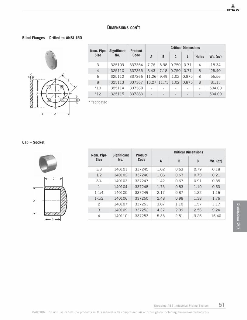
51Duraplus ABS Industrial Piping System
DIM
ENSION
ALD
ATA
CAUTION: Do not use or test the products in this manual with compressed air or other gases including air-over-water-boosters
DIMENSIONS CON’T
Cap – Socket
A
C
B
L DIA
A
B
A
C
Nom. PipeSize
SignificantNo.
ProductCode
Critical Dimensions
A B C L Holes Wt. (oz)
3 325109 337364 7.76 5.98 0.750 0.71 4 18.34
4 325110 337365 8.43 7.18 0.750 0.71 8 25.40
6 325112 337366 11.26 9.49 1.02 0.875 8 55.56
8 325113 337367 13.27 11.73 1.02 0.875 8 81.13
*10 325114 337368 - - - - - 504.00
*12 325115 337383 - - - - - 504.00
Nom. PipeSize
SignificantNo.
ProductCode
Critical Dimensions
A B C Wt. (oz)
3/8 140101 337245 1.02 0.63 0.79 0.18
1/2 140102 337246 1.06 0.63 0.79 0.21
3/4 140103 337247 1.42 0.67 0.91 0.35
1 140104 337248 1.73 0.83 1.10 0.63
1-1/4 140105 337249 2.17 0.87 1.22 1.16
1-1/2 140106 337250 2.48 0.98 1.38 1.76
2 140107 337251 3.07 1.10 1.57 3.17
3 140109 337252 4.37 2.09 2.56 9.24
4 140110 337253 5.35 2.51 3.26 16.40
* fabricated
Blind Flanges – Drilled to ANSI 150

52 Duraplus ABS Industrial Piping System
DIM
ENSI
ONAL
DATA
CAUTION: Do not use or test the products in this manual with compressed air or other gases including air-over-water-boosters
DIMENSIONS CON’T
A (A/F)
Z1
Z2
B
B
A d1
z1
z2
Union – Socket/Plastic to Plastic, EPDM ‘o’ ring
Nom.PipeSize
SignificantNo.
ProductCode
Critical Dimensions
d1 Z1 Z2 A Bpsi
RatingWt. (oz)
3/8 205101 337270 0.68 0.20 0.39 1.54 1.73 230 0.88
1/2 205102 337271 0.84 0.20 0.39 1.69 1.93 230 1.27
3/4 205103 337272 1.05 0.20 0.39 2.01 2.17 230 1.80
1 205104 337273 1.32 0.28 0.47 2.52 2.56 230 3.03
1-1/4 205105 337274 1.66 0.39 0.55 2.83 3.03 230 4.30
1-1/2 205106 337275 1.90 0.51 0.63 3.11 3.62 230 5.64
2 205107 337276 2.38 0.59 0.75 4.02 4.41 230 10.47
3 205109 337277 3.50 0.24 0.16 6.10 4.45 145 26.45
4 205110 337278 4.50 0.28 0.24 7.09 5.43 145 40.73
Nom. PipeSize
SignificantNo.
ProductCode
Critical Dimensions
Z1 Z2 A B Wt. (oz)
3/8 212101 337279 0.34 0.23 1.53 1.73 –
1/2 212102 337280 0.12 0.28 1.57 1.65 5.82
3/4 212103 337281 0.12 0.35 1.89 1.93 10.23
1 212104 337282 0.43 0.47 2.17 2.32 10.93
1-1/4 212105 337000 0.35 0.39 2.56 2.68 15.87
1-1/2 212106 337283 0.47 0.55 3.11 2.95 28.22
2 212107 337284 0.55 0.55 3.46 3.54 33.51
Union, Composite – Plastic to Brass, Socket/Female BSPT, EPDM ‘o’ ring

53Duraplus ABS Industrial Piping System
DIM
ENSION
ALD
ATA
CAUTION: Do not use or test the products in this manual with compressed air or other gases including air-over-water-boosters
DIMENSIONS CON’T
Elbow, 90° – Socket
Elbow, 45° – Socket
B
B
A
z1
z1
z1
z1
B
B
A
Nom. PipeSize
SignificantNo.
ProductCode
Critical Dimensions
Z1 A B Wt. (oz)
3/8 115101 337132 0.35 0.83 0.94 0.21
1/2 115102 337133 0.47 1.02 1.14 0.39
3/4 115103 337134 0.55 1.26 1.34 0.67
1 115104 337135 0.67 1.61 1.61 1.23
1-1/4 115105 337136 0.83 2.05 1.93 2.47
1-1/2 115106 337137 1.02 2.36 2.20 3.56
2 115107 337138 1.22 2.91 2.68 6.74
3 115109 337139 2.05 4.37 4.09 25.40
4 115110 337140 2.56 5.55 5.12 53.09
6 115112 337141 3.35 7.99 6.89 136.16
8 115113 337142 4.41 10.08 9.88 243.39
*10 115114 337011 12.50 10.75 19.50 -
*12 115115 337012 14.25 12.75 22.20 -
Nom. PipeSize
SignificantNo.
ProductCode
Critical Dimensions
Z1 A B Wt. (oz)
3/8 119101 337156 0.24 0.83 0.79 0.28
1/2 119102 337157 0.31 1.06 1.02 0.32
3/4 119103 337158 0.47 1.30 1.06 0.53
1 119104 337159 0.51 1.61 1.46 0.99
1-1/4 119105 337160 0.59 2.05 1.73 2.08
1-1/2 119106 337161 0.71 2.36 1.97 3.03
2 119107 337162 1.06 3.23 2.60 5.64
3 119109 337163 1.57 4.41 3.70 26.46
4 119110 337164 1.97 5.47 4.53 45.86
6 119112 337165 1.61 7.80 5.28 84.30
8 119113 337166 2.56 10.20 7.17 198.24
*10 119114 337013 10.00 10.75 17.00 -
*12 119115 337014 13.50 12.75 21.50 -
* fabricated sp x sp
* fabricated sp x sp

54 Duraplus ABS Industrial Piping System
DIM
ENSI
ONAL
DATA
CAUTION: Do not use or test the products in this manual with compressed air or other gases including air-over-water-boosters
DIMENSIONS CON’T
Bend, 90° – Short Radius
Nom. PipeSize
SignificantNo.
ProductCode
Critical Dimensions
Z1 A B Wt. (oz)
1/2 118102 337148 1.69 1.02 2.20 0.71
3/4 118103 337149 1.77 1.30 2.56 1.59
1 118104 337150 2.48 1.57 3.35 2.29
1-1/4 118105 337151 3.19 2.01 4.25 4.59
1-1/2 118106 337152 4.02 2.44 5.28 10.23
2 118107 337153 4.96 2.87 6.50 19.75
3 118109 337154 6.77 4.37 8.90 50.97
4 118110 337155 8.50 5.51 11.02 84.66
Nom. PipeSize
SignificantNo.
ProductCode
Critical Dimensions
B C D Wt. (oz)
3 309109 337320 3.86 12.01 15.87 54.15
4 309110 337321 5.43 16.02 21.46 121.34
6 309112 337322 8.15 24.02 32.17 332.63
8 309113 337323 14.25 31.97 46.22 672.68▲*10 309114 337384 10.25 40.00 43.38 964.47▲*12 309115 337385 9.44 18.00 25.14 1625.87
Bend, 90° Long Radius – 4 x D, spigot
B
D C
B
A
z1
▲ 10" = 6D (60" Radius)▲ 12" = 6D (72" Radius)* fabricated sp x sp
Note: Long radius bends are fabricated from the highest pressure rated pipe availablein each case. Tolerance on angle +/- 3o.

55Duraplus ABS Industrial Piping System
DIM
ENSION
ALD
ATA
CAUTION: Do not use or test the products in this manual with compressed air or other gases including air-over-water-boosters
DIMENSIONS CON’T
Bend, 45° Long Radius – 4 x D, spigot
C
D
B
Nom. PipeSize
SignificantNo.
ProductCode
Critical Dimensions
B C D Wt. (oz)
3 310109 337330 4.76 12.01 9.37 38.80
4 310110 337331 5.71 16.02 11.81 80.78
6 310112 337332 8.58 24.02 17.32 221.87
8 310113 337333 11.02 31.97 23.31 403.53▲*10 310114 337386 9.00 14.70 14.86 656.13▲*12 310115 337387 9.44 15.40 16.55 1105.87
B
C
z1
z1 z1
A
Tee, Socket
Nom. PipeSize
SignificantNo.
ProductCode
Critical Dimensions
Z1 A B C Wt. (oz)
3/8 122101 337170 0.39 0.83 1.93 0.98 0.25
1/2 122102 337171 0.43 1.02 2.28 1.14 0.46
3/4 122103 337172 0.59 1.26 2.72 1.34 0.81
1 122104 337173 0.75 1.61 3.27 1.65 1.52
1-1/4 122105 337174 0.91 2.05 3.98 1.97 3.25
1-1/2 122106 337175 0.98 2.32 4.45 2.09 4.69
2 122107 337176 1.22 2.91 5.39 2.76 8.78
3 122109 337177 1.73 4.45 8.03 4.13 32.66
4 122110 337178 2.13 5.63 9.61 4.76 69.14
6 122112 337179 3.46 8.07 13.98 6.89 169.67
8 122113 337180 3.94 10.12 18.43 9.45 338.63
*10 122114 337015 9.38 10.75 31.25 15.63 -
*12 122115 337016 10.38 12.75 35.25 17.63 -
* fabricated sp x sp
▲ 10" = 6D (60" Radius)▲ 12" = 6D (72" Radius)* fabricated sp x sp
Note: Long radius bends are fabricated from the highest pressure rated pipe availablein each case. Tolerance on angle +/- 3o.

56 Duraplus ABS Industrial Piping System
DIM
ENSI
ONAL
DATA
CAUTION: Do not use or test the products in this manual with compressed air or other gases including air-over-water-boosters
DIMENSIONS CON’T
Saddle, Socket
Note: Two saddles can be mounted diametrically opposite.
pipecenterline
pipecenterline
C
B
A
z3
z2
z1
Wye, 45°, Socket End
Spigot End – Fabricated
Note: Spigot wyes are fabricated from pipe and FRP wrapped for rigidity.Pressure ratings at 73°F are: 3" through 8" – 100 psi; 10" & 12" – 90 psi.
Nom. PipeSize
SignificantNo.
ProductCode
Critical Dimensions
d1 A B C D E FWt.(oz)
2 x 1-1/4 126129 337205 1.66 2.36 5.35 1.12 0.10 1.89 1.30 3.17
*3 x 1 126132 337207 1.32 2.99 5.51 0.93 0.13 2.36 1.81 6.24
3 x 1-1/2 126134 337208 1.90 2.99 5.51 1.16 0.13 2.36 1.81 5.57
*4 x 1 126137 337209 1.32 3.74 5.51 0.93 0.18 2.87 2.36 9.70
4 x 2 126140 337210 2.38 3.74 5.51 1.37 0.18 2.87 2.36 8.11
*6 x 1 126143 337211 1.32 2.80 5.98 0.93 0.26 2.87 3.46 9.53
6 x 1-1/2 126145 337212 1.90 2.80 5.98 1.16 0.26 2.87 3.46 9.42
6 x 2 126146 337213 2.38 2.80 5.98 1.37 0.26 2.87 3.46 7.94
Nom. PipeSize
SignificantNo.
ProductCode
Critical Dimensions
Z1 Z2 Z3 A B CWt.(oz)
1/2 128102 337214 1.34 0.28 1.06 1.10 2.68 1.73 1.06
3/4 128103 337215 1.61 0.31 1.26 1.30 3.19 2.05 1.59
1 128104 337216 1.93 0.35 1.54 1.61 3.82 2.48 2.82
1-1/4 128105 337217 2.40 0.39 2.05 1.97 4.61 3.15 6.84
1-1/2 128106 337218 3.15 0.47 2.64 2.36 5.51 3.82 10.51
2 128107 337219 3.54 0.59 2.87 2.91 6.69 4.45 19.26
Nom. PipeSize
SignificantNo.
ProductCode
Critical Dimensions
Z1 Z2 Z3 A B CWt.(oz)
3 128109 337220 11.00 3.50 7.00 3.50 17.00 10.00 152.31
4 128110 337221 13.50 4.00 8.50 4.50 19.50 12.00 203.18
6 128112 337222 16.50 4.50 10.50 6.625 26.50 15.50 279.16
8 128113 337223 18.00 4.50 13.00 8.625 30.00 19.00 459.02
10 128114 337224 19.00 4.50 14.50 10.76 35.00 22.50 545.33
12 128115 337225 24.00 5.50 19.00 12.76 42.00 28.00 938.43
* fabricated
F
C
d1
D
A
B
E
C
B
A
z3
z2
z1

57Duraplus ABS Industrial Piping System
DIM
ENSION
ALD
ATA
CAUTION: Do not use or test the products in this manual with compressed air or other gases including air-over-water-boosters
DIMENSIONS CON’T
Reducer Bushing – Spigot x Socket
Reducer Bushing – Spigot x Female BSBT
Nom.Pipe Size
SignificantNo.
ProductCode
Critical Dimensions
Z1 A Wt. (oz)
1/2 x 3/8 109121 337050 0.08 0.67 0.25
3/4 x 1/2 109122 337051 0.12 0.79 0.28
1 x 1/2 109123 337052 0.24 0.91 0.81
1 x 3/4 109124 337053 0.16 0.94 0.53
*1-1/4 x 1/2 109116 337045 0.47 1.10 0.74
*1-1/4 x 3/4 109117 337046 0.31 1.10 0.67
1-1/4 x 1 109125 337054 0.20 1.10 0.71
*1-1/2 x 1/2 109118 337047 0.51 1.18 0.92
*1-1/2 x 3/4 109119 337048 0.39 1.18 0.95
1-1/2 x 1 109126 337055 0.28 1.18 0.67
1-1/2 x 1 1/4 109127 337056 0.16 1.22 1.41
*2 x 3/4 109120 337049 0.59 1.50 1.59
*2 x 1 109128 337057 0.59 1.50 1.59
*2 x 1-1/4 109129 337058 0.43 1.50 1.38
2 x 1-1/2 109130 337059 0.28 1.46 1.48
*3 x 1-1/2 109134 337061 0.83 2.01 4.58
*3 x 2 109135 337062 0.59 2.01 6.28
4 x 3 109141 337064 0.47 2.56 9.77
*6 x 4 109147 337065 1.06 3.66 23.49
*8 x 6 109152 337066 0.91 4.33 41.80
*10 x 8 109157 337067 0.50 5.87 224.00
*12 x 10 109162 337068 0.50 6.87 320.00
A
z1
z1
*
* fabricated
A
z1
Nom.Pipe Size
SignificantNo.
ProductCode
Critical Dimensions
Z1 A Wt. (oz)
1/2 x 3/8 111121 337072 0.24 0.67 0.14
3/4 x 1/2 111122 337073 0.20 0.79 0.25
1 x 3/4 111124 337074 0.24 0.91 0.42

58 Duraplus ABS Industrial Piping System
DIM
ENSI
ONAL
DATA
CAUTION: Do not use or test the products in this manual with compressed air or other gases including air-over-water-boosters
B C
Nom. Pipe Size
SignificantNo.
ProductCode
Critical Dimensions
B C Z1 AWt.(oz)
*1/2 x 3/8 114121 337120 - - - - -
3/4 x 1/2 114122 337121 1.26 1.02 0.28 1.73 0.39
1 x 3/4 114124 337122 1.61 1.30 0.35 2.09 0.74
1-1/4 x 1 114125 337123 2.05 1.61 0.39 2.48 1.38
1-1/2 x 1-1/4 114127 337124 2.32 2.01 0.31 2.68 2.05
2 x 1-1/2 114130 337125 2.91 2.32 0.47 3.23 3.53
3 x 2 114135 337126 4.25 2.95 1.02 4.49 11.29
4 x 3 114141 337127 5.35 4.25 0.79 5.35 19.68
6 x 4 114147 337128 8.07 5.51 2.17 8.39 69.67
8 x 6 114152 337129 10.08 7.80 1.97 10.35 120.28
*10 x 8 114157 337130 8.63 10.75 1.00 12.25 336.00
*12 x 10 114162 337131 10.75 12.75 1.00 14.25 480.00
Reducer Coupling – Socket
* fabricated sp x sp
Female Adapter – Socket x FPT
Nom. PipeSize
SignificantNo.
ProductCode
Critical Dimensions
d1 Z1 A B Wt. (oz)
1/2 101102 337094 0.84 0.12 1.10 1.46 0.28
3/4 101103 337095 1.05 0.12 1.42 1.61 0.49
1 101104 337096 1.32 0.12 1.73 1.89 1.06
1-1/2 101106 337097 1.90 0.12 2.48 2.60 2.29
2 101107 337098 2.38 0.12 3.11 2.76 4.02

59Duraplus ABS Industrial Piping System
DIM
ENSION
ALD
ATA
CAUTION: Do not use or test the products in this manual with compressed air or other gases including air-over-water-boosters
DIMENSIONS CON’T
Female Adapter – Spigot x BSPT
d1
B
z1
Nom. PipeSize
SignificantNo.
ProductCode
Critical Dimensions
Z1 A B Wt. (oz)
1/2 153102 337257 0.63 1.06 1.50 0.28
3/4 153103 337258 0.71 1.42 1.73 0.49
1 153104 337259 0.83 1.69 1.97 0.85
1-1/4 153105 337260 0.87 2.17 2.36 1.73
1-1/2 153106 337261 0.98 2.48 2.60 2.10
2 153107 337262 1.14 3.07 3.07 4.55
Nipple – Spigot x MPT
Nom. PipeSize
SignificantNo.
ProductCode
Critical Dimensions
A B Wt. (oz)
3/8 314101 337340 3.00 0.75 0.26
1/2 314102 337341 3.00 0.90 0.35
3/4 314103 337342 3.00 1.00 0.46
1 314104 337343 3.00 1.10 0.69
1-1/4 314105 337344 3.00 1.15 1.07
1-1/2 314106 337345 3.00 1.35 1.39
2 314107 337346 3.00 1.35 2.08
3 314109 337347 6.00 1.50 11.00
4 314110 337348 6.00 2.10 20.00

60 Duraplus ABS Industrial Piping System
DIM
ENSI
ONAL
DATA
CAUTION: Do not use or test the products in this manual with compressed air or other gases including air-over-water-boosters
DIMENSIONS CON’T
Diaphragm Valve – Spigot, EPDM
Note: Other diaphragm materials available upon request* 3" and 4" are spigot ended
Nom. PipeSize
SignificantNo.
ProductCode
Critical Dimensions
B D F Wt. (oz)
1/2 155102 337264 0.91 0.55 0.51 0.20
3/4 155103 337265 1.10 0.59 0.55 0.30
1 155104 337266 1.18 0.67 0.67 0.40
1-1/4 155105 337267 1.38 0.87 0.87 1.10
1-1/2 155106 337268 1.50 0.87 1.06 1.30
2 155107 337269 1.77 1.02 1.46 1.80
Plug – Male BSPT
Nom. PipeSize
SignificantNo.
ProductCode
Critical Dimensions (inches)
d H L B1 B H1 h JWt.(lbs)
1/2 H0UMA102 337110 0.84 4.88 0.63 1.02 3.74 3.54 0.47 M6 1.54
3/4 H0UMA103 337111 1.05 5.67 0.75 1.02 3.74 3.54 0.47 M6 1.54
1 H0UMA104 337112 1.32 6.06 0.91 1.02 3.74 3.54 0.47 M6 1.54
1-1/4 H0UMA105 337113 1.66 6.85 1.06 1.57 4.96 4.53 0.71 M8 3.31
1-1/2 H0UMA106 337114 1.90 7.64 1.26 1.57 4.96 4.53 0.71 M8 3.31
2 H0UMA107 337115 2.38 8.82 1.54 1.57 5.83 5.51 0.71 M8 5.29
* 3 H0VMA209 337649 3.50 11.81 2.01 2.17 8.86 8.46 0.91 M12 15.43
* 4 H0VMA210 337116 4.50 13.78 – 2.72 11.61 9.84 0.91 M12 23.15

61Duraplus ABS Industrial Piping System
DIM
ENSION
ALD
ATA
CAUTION: Do not use or test the products in this manual with compressed air or other gases including air-over-water-boosters
DIMENSIONS CON’T
True Union VKD Valve – Socket, EPDM Seals
Nom. PipeSize
SignificantNo.
ProductCode
Critical Dimensions
d H L Z H1 E B1 B C1 C
1/2 902102 337802 0.84 4.61 0.89 2.83 2.56 2.13 1.14 2.13 1.57 2.64
3/4 902103 337803 1.05 5.08 1.00 3.07 2.76 2.56 1.36 2.56 1.93 3.35
1 902104 337804 1.32 5.59 1.13 3.33 3.07 2.87 1.54 2.74 1.93 3.35
1-1/4 902105 337805 1.66 6.38 1.26 3.86 3.46 3.39 1.81 3.25 2.52 4.25
1-1/2 902106 337806 1.90 6.77 1.38 4.02 3.66 3.86 2.05 3.50 2.52 4.25
2 902107 337807 2.38 7.83 1.50 4.83 4.37 4.80 2.44 4.25 2.99 5.28
2-1/2 902108 337808 2.88 9.25 1.75 5.75 5.24 6.46 3.43 6.46 6.89 8.86
3 902109 337809 3.50 10.63 1.89 6.85 5.87 7.99 4.13 6.97 10.71 12.87
4 902110 337810 4.50 12.13 2.26 7.60 6.57 9.37 5.08 7.68 12.99 15.16
Nom. PipeSize
SignificantNo.
ProductCode
Critical Dimensions
A B psiWt.(oz)
3/8 836101 337727 1.89 3.74 150 3.1
1/2 836102 337728 1.89 3.74 150 2.8
3/4 836103 337729 2.32 4.41 150 4.9
1 836104 337730 2.72 4.88 150 7.1
1-1/4 836105 337731 3.78 5.83 150 18.5
1- 1/2 836106 337732 3.78 5.83 150 17.6
2 836107 337733 4.06 6.97 150 22.9
3 836109 337734 7.01 8.00 150 80.2
Ball Check Valve – Socket, EPDM Seals
Sizes 1/2" to 2" Sizes 2-1/2" to 4"

62 Duraplus ABS Industrial Piping System
DIM
ENSI
ONAL
DATA
CAUTION: Do not use or test the products in this manual with compressed air or other gases including air-over-water-boosters
DIMENSIONS CON’T
Mesh: 1.5mm, ASTM mesh size 30, Polypropylene.
Disk: Shall be ABS. Other materials and larger sizes are available upon request.
FK Butterfly Valve
Strainers – Socket, EPDM Seals
Nom.Pipe Size
SignificantNo.
ProductCode
Critical Dimensions
d L Z H E B AMAX
1/2 846102 337739 0.84 0.63 4.06 5.31 2.17 2.83 4.92
3/4 846103 337740 1.05 0.75 4.72 6.22 2.60 3.31 5.71
1 846104 337741 1.32 0.87 5.20 6.93 2.95 3.74 6.50
1-1/4 846105 337742 1.66 1.02 6.10 8.15 3.43 4.37 7.48
1-1/2 846106 337743 1.90 1.22 7.13 9.57 3.94 4.72 8.27
2 846107 337744 2.38 1.50 8.72 11.73 4.72 5.47 9.45
Nom.PipeSize
SignificantNo.
ProductCode
Critical Dimensions
d AMIN
AMAX
B1 B2 B3 C C1 f H ZWt.(oz.)
2 681107 337656 1.97 5.04 5.70 4.69 3.15 6.46 10.70 4.33 0.75 6.50 1.81 3.23
3 681109 337657 3.15 5.71 6.30 5.24 3.66 7.00 10.70 4.33 0.75 7.28 1.93 4.11
4 681110 337658 3.94 6.50 7.50 5.79 4.21 7.56 10.70 4.33 0.75 8.31 2.20 4.88
6 681112 337659 5.91 9.10 9.53 7.10 5.30 8.86 12.99 4.33 0.91 10.60 2.80 8.47
8 681113 337660 7.87 11.02 11.73 8.94 6.34 10.71 16.54 4.80 0.91 12.72 2.80 14.35

63Duraplus ABS Industrial Piping System
SPECIFICATION
S
CAUTION: Do not use or test the products in this manual with compressed air or other gases including air-over-water-boosters
SECTION SEVEN: SPECIFICATIONS
Sample Specification
General
Duraplus ABS is designed for industrial pressure pipe applications where the extremely high-impact resistanceand ductility of the material offers some insurance againstinternal and external shock loadings and site abuseconditions. It’s unique combination of ABS properties –non-toxicity, purity, corrosion- and chemical-resistance,toughness, low-hydraulic resistance, and the ability toperform over a wide temperature range (-40ºF to +176ºF)ensures excellent in-service performance and system life.
Material Specification
Pipe and fittings shall be manufactured from a copolymericmaterial – Acrylonitrile Butadiene Styrene (ABS) – conforming to a 43232 cell classification in accordancewith ASTM D3965.
Material for both pipe and fittings shall have a design stressof not less than 2,000 psi, and shall be designed with a2 to 1 safety factor for a 50 year lifespan when operated under continuous pressure.
The material shall have an izod impact resistance value ofnot less than 6 ft./lb. at 73ºF and 3 ft./lb. at -22ºF, whentested in accordance with ASTM D256, method ‘A’.
Pipe
Pipes shall be manufactured by IPEX and designed on aStandard Dimension Ratio (SDR) basis to give variouspressure ratings as described below:
Fittings
Fittings shall be of the socket type, designed for solventwelding as supplied by IPEX.
Fittings shall be designed and manufactured so that theywithstand the continuous pressures applicable to the maximum pressure native of the pipe.
Solvent Cement
All joints shall be made with Gray Duraplus ABS solventcement as supplied by IPEX.
The solvent cement shall be designed to withstandcontinuous applied pressures up to 230 psi at 73ºF.
Design and Installation
The design and installation of ABS pressure systems shall beperformed in accordance with the recommendations detailedin the Handling and Installation section of this manual,local and national regulations where applicable.
To ensure the full integrity of the completed system,all components shall be supplied by IPEX.
Pipe Class SDRContinuous Pressure
Rating at 73°F (23°C)
Size Range
Class 90 psi SDR 24.0 90 psi (6 bar) 10" & 12"
Class 115 psi SDR 19.0 115 psi (8 bar) 6" & 8"
Class 145 psi SDR 15.5 145 psi (10 bar) 1" to 8"
Class 180 psi SDR 12.5 180 psi (12 bar) 1" to 6"
Class 230 psi SDR 10.0 230 psi (16 bar) 3/8" to 4"

64 Duraplus ABS Industrial Piping System
CAUTION: Do not use or test the products in this manual with compressed air or other gases including air-over-water-boosters
This page intentionally
left blank

65Duraplus ABS Industrial Piping System
APPEN
DIX
CAUTION: Do not use or test the products in this manual with compressed air or other gases including air-over-water-boosters
APPENDIX A: CONVERSION CHARTS
Contents of Pipe
VolumeVolume of a pipe is computed by: V = 1/4 ID2 x π x L x 12
Where: V = volume (in cubic inches)
ID = inside diameter (in inches)
π = 3.14159
L = length of pipe (in feet)
Weight1 U.S. gallon @ 50°F....... 8.33 lbs. x sg
1 cubic foot .................... 62.35 lbs. x sg
...................................... 7.48 U.S. gal.
1 cu. ft. of water @ 50°F . 62.41 lbs.
1 cu. ft. of water @ 39.2°F 62.43 lbs.
(39.2°F is water temp. at its greatest density)
1 kilogram ...................... 2.2 lbs.
1 imperial gallon of water. 10.0 lbs.
1 pound.......................... 12 U.S. gal ÷ sg
...................................... .016 cu. ft. ÷ sg
Capacity or Flow
1 U.S. gallon per minute (gpm) 0.134 cfm
......500 lb. per hr. x sp. gr.
......500 lb. per hr. 1 gpm ÷ sp. gr.
1 cu. ft. per minute (cfm) ......449 gph
1 cu. ft. per second (cfs) ......449 gpm
1 acre foot per day ......227 gpm
1 acre inch per hour ......454 gpm
1 cubic meter per minute ......264.2 gpm
1,000,000 gal. per day ......595 gpm
Brake H.P. = (gpm) (total head in ft.) (specific gravity)
(3960) (pump eff.)
Capacities in Cubic Feet and United States Gallons (231 Cubic Inches) per foot of Length
Dia. in. Dia. ft.
For 1 Foot Length
Dia. in. Dia. ft.
For 1 Foot Length
Dia. in. Dia. ft.
For 1 Foot Length
ft.3
Also Areain. ft.2
U.S. Gal.(231 in.3)
ft.3
Also Areain. ft.2
U.S. Gal.(231 in.3)
ft.3
Also Areain. ft.2
U.S. Gal.(231 in.3)
1/4 0.0208 0.0003 0.0026 4-1/4 0.3542 0.0985 0.7370 10-1/2 0.8750 0.6013 4.4980
5/16 0.0260 0.0005 0.0040 4-1/2 0.3750 0.1105 0.8263 10-3/4 0.8958 0.6303 4.7140
3/8 0.0313 0.0008 0.0057 4-3/4 0.3958 0.1231 0.9205 11 0.9167 0.6600 4.9370
7/16 0.0365 0.0010 0.0078 5 0.4167 0.1364 1.0200 11-1/4 0.9375 0.6903 5.1630
1/2 0.0417 0.0014 0.0102 5-1/4 0.4375 0.1503 1.1240 11-1/2 0.9583 0.7213 5.3950
9/16 0.0469 0.0017 0.0129 5-1/2 0.4583 0.1650 1.2340 11-3/4 0.9792 0.7530 5.6330
5/8 0.0521 0.0021 0.0159 5-3/4 0.4792 0.1803 1.3490 12 1.0000 0.7854 5.8760
11/16 0.0573 0.0026 0.0193 6 0.500 0.1963 1.4690 12-1/2 1.0420 0.8523 6.3750
3/4 0.0625 0.0031 0.0230 6-1/4 0.5208 0.2130 1.5940 13 1.0830 0.9218 6.8950
13/16 0.0677 0.0036 0.0270 6-1/2 0.5417 0.2305 1.7240 13-1/2 1.1250 0.9940 7.4350
7/8 0.0729 0.0042 0.0312 6-3/4 0.5625 0.2485 1.8590 14 1.1670 1.0690 7.9970
15/16 0.0781 0.0048 0.0359 7 0.5833 0.2673 1.9990 14-1/2 1.2080 1.1470 8.5780
1 0.0833 0.0055 0.0408 7-1/4 0.6042 0.2868 2.1440 15 1.2500 1.2270 9.1800
1-1/4 0.1042 0.0085 0.0638 7-1/2 0.6250 0.3068 2.2950 15-1/2 1.2920 1.3100 9.8010
1-1/2 0.1250 0.0123 0.0918 7-3/4 0.6458 0.3275 2.4500 16 1.3330 1.3960 10.4400
1-3/4 0.1458 0.0168 0.1250 8 0.6667 0.3490 2.6110 16-1/2 1.3750 1.4850 11.1100
2 0.1667 0.0218 0.1632 8-1/4 0.6875 0.3713 2.7770
2-1/4 0.1875 0.0276 0.2066 8-1/2 0.7083 0.3940 2.9480
2-1/2 0.2083 0.0341 0.2550 8-3/4 0.7292 0.4175 3.1250
2-3/4 0.2292 0.0413 0.3085 9 0.7500 0.4418 3.3050
3 0.2500 0.0491 0.3673 9-1/4 0.7708 0.4668 3.4920
3-1/4 0.2708 0.0576 0.4310 9-1/2 0.7917 0.4923 3.6820
3-1/2 0.2917 0.0668 0.4998 9-3/4 0.8125 0.5185 3.8790
3-3/4 0.3125 0.0767 0.5738 10 0.8333 0.5455 4.0810
4 0.3333 0.0873 0.6528 10-1/4 0.8542 0.5730 4.2860

66 Duraplus ABS Industrial Piping System
APPE
NDI
X
CAUTION: Do not use or test the products in this manual with compressed air or other gases including air-over-water-boosters
Frac
tion
s1
/64
1/3
23
/64
1/1
65
/64
3/3
27
/64
1/8
9/6
45
/32
11
/64
3/1
61
3/6
47
/32
15
/64
1/4
Dec
imal
s.0
15
62
50
31
25
.04
68
75
.06
25
.07
81
25
.09
37
5.1
09
37
5.1
25
.14
06
25
.15
62
5.1
71
87
5.1
87
5.2
03
12
52
18
75
.23
47
5.2
50
mm
.39
7.7
94
1.1
91
1.5
88
1.9
84
2.3
81
2.7
78
3.1
75
3.5
72
3.9
69
4.3
66
4.7
63
5.1
59
5.5
56
5.9
53
6.3
50
Frac
tion
s1
7/6
49
/32
19
/64
5/1
62
1/6
41
1/3
22
3/6
43
/82
5/6
41
3/3
22
7/6
47
/16
29
/64
15
/32
31
/64
1/2
Dec
imal
s6
56
25
.28
12
5.2
96
87
5.3
12
5.3
28
12
5.3
43
75
.35
93
75
.37
5.3
90
62
5.4
06
25
.42
18
75
.43
75
.45
31
25
.46
87
5.4
84
37
5.5
00
mm
6.7
47
7.1
44
7.5
41
7.9
38
8.3
34
8.7
31
9.1
28
9.5
25
9.9
22
10
.31
91
0.7
16
11
.11
31
1.5
09
11
.90
61
2.3
03
12
.70
0
Frac
tion
s3
3/6
41
7/3
23
5/6
49
/16
37
/64
19
/32
39
/64
5/8
41
/64
21
/32
43
/64
11
/16
45
/64
23
/32
47
/64
3/4
Dec
imal
s.5
15
62
5.5
31
25
.54
68
75
.56
25
.57
81
25
.59
37
5.6
09
37
5.6
25
.64
06
25
.65
62
5.6
71
87
5.6
87
5.7
03
12
5.7
18
75
.73
43
75
.75
0
mm
13
.09
71
3.4
94
13
.89
11
4.2
88
14
.68
41
5.0
81
15
.47
81
5.8
75
16
.27
21
6.6
69
17
.06
61
7.4
63
17
.85
91
8.2
56
18
.65
31
9.0
50
Frac
tion
s4
9/6
42
5/3
25
1/6
41
3/1
65
3/6
42
7/3
25
5/6
47
/85
7/6
42
9/3
25
9/6
41
5/1
66
1/6
43
1/3
26
3/6
41
Dec
imal
s.7
65
62
5.7
81
25
.79
68
75
.81
25
.82
81
25
.83
47
5.8
59
37
5.8
75
.89
06
25
.90
62
5.9
21
87
5.9
37
5.9
53
12
5.9
68
75
.98
43
75
1.0
00
mm
19
.44
71
9.8
44
20
.24
12
0.6
38
21
.03
42
1.4
31
21
.82
82
2.2
25
22
.62
22
3.0
19
23
.41
62
3.8
13
24
.20
92
4.6
06
25
.00
32
5.4
00
CONVERSION CHARTS
lb./i
n.2
mm
Hg
(Tor
r)(a
t 0°
C)
1.00
0
3.61
27x1
0-2
1.42
23x1
0-2
4.91
16x1
0-1
1.93
37x1
0-2
1.45
04x1
05
1.45
04x1
0-4
1.42
24x1
01
1.45
04x1
01
1.46
96x1
01
6.94
45x1
0-3
4.33
52x1
0-1
2.76
80x1
01
1.00
00
0.39
37
1.35
96x1
01
5.35
25x1
0-1
4.01
47x1
0-4
4.01
47x1
0-3
3.93
71x1
02
4.01
47x1
02
4.06
79x1
02
1.92
23x1
0-1
1.20
00x1
01
7.03
08x1
01
2.54
00
1.00
00
3.45
32x1
01
1.35
95
1.01
97x1
0-3
1.01
97x1
0-2
1.00
003x
103
1.01
97x1
03
1.03
33x1
03
4.88
2x10
-1
3.04
80x1
01
2.03
60
7.35
54x1
0-2
2.89
58x1
0-2
1.00
00
3.93
70x1
0-2
2.95
30x1
0-5
2.95
30x1
0-4
2.89
59x1
01
2.95
30x1
01
2.99
21x1
01
1.41
39x1
0-2
8.82
6x10
-1
5.17
15x1
01
1.86
83
0.73
55
2.54
00x1
01
1.00
00
7.50
06x1
0-4
7.50
06x1
0-3
7.35
56x1
02
7.50
06x1
02
7.60
00x1
02
3.59
1x10
-1
2.24
19x1
01
6.89
48x1
04
2.49
808x
103
9.80
64x1
02
3.38
64x1
04
1.33
32x1
03
1.00
00
1.00
00x1
01
9.80
60x1
05
1.00
00x1
06
1.01
33x1
06
4.78
80x1
02
2.98
90x1
04
6.89
48x1
03
2.49
08x1
02
9.80
64x1
01
3.38
64x1
03
1.33
32x1
02
1.00
00x1
0-1
1.00
00
9.80
60x1
04
1.00
00x1
05
1.01
33x1
05
4.78
80x1
01
2.98
90x1
03
7.03
06x1
0-2
2.53
99x1
0-3
9.99
97x1
0-4
3.45
32x1
0-2
1.35
95x1
0-3
1.01
97x1
0-6
1.01
97x1
0-5
1.00
00
1.01
97
1.03
32
4.88
24x1
0-4
3.04
79x1
0-2
6.89
47x1
0-2
2.49
08x1
0-3
9.80
64x1
0-4
3.38
64x1
0-2
1.33
32x1
0-3
1.00
00x1
0-6
1.00
00x1
0-5
9.80
60x1
0-1
1.00
00
1.01
13
4.78
80x1
0-4
2.98
90x1
0-2
6.80
45x1
0-2
2.45
82x1
0-3
9.67
81x1
0-4
3.34
21x1
0-2
1.31
58x1
0-3
9.86
92x1
0-7
9.86
92x1
0-6
9.67
8x10
-1
9.86
92x1
0-1
1.00
00
4.72
54x1
0-4
2.94
99x1
0-2
1.44
00x1
02
5.20
22
2.04
81
7.07
27x1
01
2.78
45
2.08
86x1
0-3
2.08
85x1
0-2
2.04
82x1
03
2.08
85x1
03
2.11
62x1
03
1.00
00
6.24
27x1
01
2.30
67
8.33
33x1
0-2
3.28
08x1
0-2
1.13
30
4.46
05x1
0-2
3.34
56x1
0-5
3.34
56x1
0-4
3.28
09x1
01
3.34
56x1
01
3.39
00x1
01
1.60
19x1
0-2
1.00
00
in.H
20(a
t +39
.2°F
)cm
H2
0(a
t +4
°C)
in.
Hg
(at
+3
2°F
)
dyne
/cm
2
(1m
bar)
new
ton/
m2
(PA
SC
AL)
kgm
/cm
2
bar
atm
. (A
n)
ft. H
20(a
t +39
.2°F
)
lb./f
t.2
Giv
enlb
./in.
2in
.H20
(at
+3
9.2
°F)
cmH
20
(at
+4
°C)
in. H
g(a
t +3
2°F
)m
m H
g (T
orr)
(at 0
°C)
dyne
/cm
2
(1m
bar)
new
ton/
m2
(PA
SC
AL)
kgm
/cm
2ba
rat
m.
(An)
lb./f
t.2
ft.H
20(a
t +39
.2°F
)
Pres
sure
Con
vers
ion
BY F
ACTO
R TO
OBT
AIN
Multiply Given Number of
Deci
mal
and
Mill
imet
er E
quiv
alen
ts o
f Fra
ctio
ns
Inch
esIn
ches
Inch
esIn
ches

67Duraplus ABS Industrial Piping System
APPEN
DIX
CAUTION: Do not use or test the products in this manual with compressed air or other gases including air-over-water-boosters
CONVERSION CHARTS
(1 micron = 0.001 millimeter)
Units of LengthMultiply units in left column by proper factor below
in. ft. yd. mile mm cm m km
1 inch 1 0.0833 0.0278 - 25.4 2.540 0.0254 -
1 foot 12 1 0.3333 - 304.8 30.48 0.3048 -
1 yard 36 3 1 - 914.4 91.44 0.9144 -
1 mile - 5280 1760 1 - - 1609.3 1.609
1 millimeter 0.0394 0.0033 - - 1 0.100 0.001 -
1 centimeter 0.3937 0.0328 0.0109 - 10 1 0.01 -
1 meter 39.37 3.281 1.094 - 1000 100 1 0.001
1 kilometer - 3281 1094 0.6214 - - 1000 1
Units of WeightMultiply units in left column by proper factor below
grain oz. lb. ton gram kg metric ton
1 grain 1 - - - 0.0648 - -
1 ounce 437.5 1 0.0625 - 28.35 0.0283 -
1 pound 7000 16 1 0.0005 453.6 0.4536 -
1 ton - 32,000 2000 1 - 907.2 0.9072
1 gram 15.43 0.0353 - - 1 0.001 -
1 kilogram - 35.27 2.205 - 1000 1 0.001
1 metric ton - 35,274 2205 1.1023 - 1000 1
Units of DensityMultiply units in left column by proper factor below
lb./in.3 lb./ft.3 lb./gal. g/cm3 g/liter
1 pound/in.3 1 1728 231.0 27.68 27,680
1 pound/ft.3 - 1 0.1337 0.0160 16.019
1 pound/gal. 0.00433 7.481 1 0.1198 119.83
1 gram/cm3 0.0361 62.43 8.345 1 1000.0
1 gram/liter - 0.0624 0.00835 0.001 1
Units of AreaMultiply units in left column by proper factor below
in.2 in.2 acre mile2 cm2 m2 hectare
1 inch2 1 1 - - 6.452 - -
1 foot2 144 144 - - 929.0 0.0929 -
1 acre - - 1 0.0016 - 4047 0.4047
1 mile2 - - 640 1 - - 259.0
1 centimeter2 0.1550 0.1550 - - 1 0.0001 -
1 meter2 1550 1550 - - 10,000 1 -
1 hectare - - 2.471 - - 10,000 1
Units of VolumeMultiply units in left column by proper factor below
in.3 ft.3 yd.3 cm.3 meter3 liter U.S. gal. Imp. gal.
1 inch3 1 - - 16.387 - 0.0164 - -
1 foot3 1728 1 0.0370 28,317 0.0283 28.32 7.481 6.229
1 yard3 46,656 27 1 - 0.7646 764.5 202.0 168.2
1 centimeter3 0.0610 - - 1 - 0.0010 - -
1 meter3 61,023 35.31 1.308 1,000,000 1 999.97 264.2 220.0
1 liter 61.025 0.0353 - 1000.028 0.0010 1 0.2642 0.2200
1 U.S. gallon 231 0.1337 - 3785.4 - 3.785 1 0.8327
1 Imp. gallon 277.4 0.1605 - 4546.1 - 4.546 1.201 1
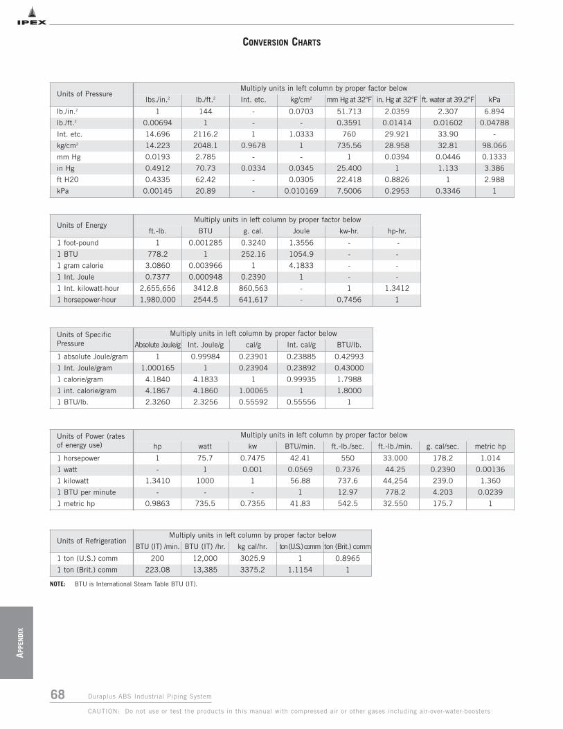
68 Duraplus ABS Industrial Piping System
APPE
NDI
X
CAUTION: Do not use or test the products in this manual with compressed air or other gases including air-over-water-boosters
CONVERSION CHARTS
NOTE: BTU is International Steam Table BTU (IT).
Units of PressureMultiply units in left column by proper factor below
lbs./in.2 lb./ft.2 Int. etc. kg/cm2 mm Hg at 32°F in. Hg at 32°F ft. water at 39.2°F kPa
lb./in.2 1 144 - 0.0703 51.713 2.0359 2.307 6.894
lb./ft.2 0.00694 1 - - 0.3591 0.01414 0.01602 0.04788
Int. etc. 14.696 2116.2 1 1.0333 760 29.921 33.90 -
kg/cm2 14.223 2048.1 0.9678 1 735.56 28.958 32.81 98.066
mm Hg 0.0193 2.785 - - 1 0.0394 0.0446 0.1333
in Hg 0.4912 70.73 0.0334 0.0345 25.400 1 1.133 3.386
ft H20 0.4335 62.42 - 0.0305 22.418 0.8826 1 2.988
kPa 0.00145 20.89 - 0.010169 7.5006 0.2953 0.3346 1
Units of EnergyMultiply units in left column by proper factor below
ft.-lb. BTU g. cal. Joule kw-hr. hp-hr.
1 foot-pound 1 0.001285 0.3240 1.3556 - -
1 BTU 778.2 1 252.16 1054.9 - -
1 gram calorie 3.0860 0.003966 1 4.1833 - -
1 Int. Joule 0.7377 0.000948 0.2390 1 - -
1 Int. kilowatt-hour 2,655,656 3412.8 860,563 - 1 1.3412
1 horsepower-hour 1,980,000 2544.5 641,617 - 0.7456 1
Units of Power (ratesof energy use)
Multiply units in left column by proper factor below
hp watt kw BTU/min. ft.-lb./sec. ft.-lb./min. g. cal/sec. metric hp
1 horsepower 1 75.7 0.7475 42.41 550 33.000 178.2 1.014
1 watt - 1 0.001 0.0569 0.7376 44.25 0.2390 0.00136
1 kilowatt 1.3410 1000 1 56.88 737.6 44,254 239.0 1.360
1 BTU per minute - - - 1 12.97 778.2 4.203 0.0239
1 metric hp 0.9863 735.5 0.7355 41.83 542.5 32.550 175.7 1
Units of RefrigerationMultiply units in left column by proper factor below
BTU (IT) /min. BTU (IT) /hr. kg cal/hr. ton (U.S.) comm ton (Brit.) comm
1 ton (U.S.) comm 200 12,000 3025.9 1 0.8965
1 ton (Brit.) comm 223.08 13,385 3375.2 1.1154 1
Units of SpecificPressure
Multiply units in left column by proper factor below
Absolute Joule/g Int. Joule/g cal/g Int. cal/g BTU/lb.
1 absolute Joule/gram 1 0.99984 0.23901 0.23885 0.42993
1 Int. Joule/gram 1.000165 1 0.23904 0.23892 0.43000
1 calorie/gram 4.1840 4.1833 1 0.99935 1.7988
1 int. calorie/gram 4.1867 4.1860 1.00065 1 1.8000
1 BTU/lb. 2.3260 2.3256 0.55592 0.55556 1

69Duraplus ABS Industrial Piping System
APPEN
DIX
CAUTION: Do not use or test the products in this manual with compressed air or other gases including air-over-water-boosters
CONVERSION CHARTS
The following formulas may also be used for converting Celsius or Fahrenheit degrees into the other scales.
Degrees Celsius °C = (°F - 32) Degrees Fahr. °F = °C + 32
Degrees Kelvin °T = °C + 273.2 Degrees Rankine °R = °F + 459.7
59
95
Temperature Conversion
°F °C °F °C °F °C °F °C °F °C
-459.4 -273 1 -17.2 61 16.1 300 149 900 482-450 -268 2 -16.7 62 16.7 310 154 910 488-440 -262 3 -16.1 63 17.2 320 160 920 493-430 -257 4 -15.6 64 17.8 330 166 930 499-420 -251 5 -15.0 65 18.3 340 171 940 504-410 -246 6 -14.4 66 18.9 350 177 950 510-400 -240 7 -13.9 67 19.4 360 182 960 516-390 -234 8 -13.3 68 20.0 370 188 970 521-380 -229 9 -12.8 69 20.6 380 193 980 527-370 -223 10 -12.2 70 21.1 390 199 990 532-360 -218 11 -11.7 71 21.7 400 204 1000 538-350 -212 12 -11.1 72 22.2 410 210 1020 549-340 -207 13 -10.6 73 22.8 420 215 1040 560-330 -201 14 -10.0 74 23.3 430 221 1060 571-320 -196 15 -9.4 75 23.9 440 227 1080 582-310 -190 16 -8.9 76 24.4 450 232 1100 593-300 -184 17 -8.3 77 25.0 460 238 1120 604-290 -179 18 -7.8 78 25.6 470 243 1140 616-280 -173 19 -7.2 79 26.1 480 249 1160 627-273 -169 20 -6.7 80 26.7 490 254 1180 638-270 -168 21 -6.1 81 27.2 500 260 1200 649-260 -162 22 -5.6 82 27.8 510 266 1220 660-250 -157 23 -5.0 83 28.3 520 271 1240 671-240 -151 24 -4.4 84 28.9 530 277 1260 682-230 -146 25 -3.9 85 29.4 540 282 1280 693-220 -140 26 -3.3 86 30.0 550 288 1300 704-210 -134 27 -2.8 87 30.6 560 293 1350 732-200 -129 28 -2.2 88 31.1 570 299 1400 760-190 -123 29 -1.7 89 31.7 580 304 1450 788-180 -118 30 -1.1 90 32.2 590 310 1500 816-170 -112 31 -0.6 91 32.8 600 316 1550 843-160 -107 32 0.0 92 33.3 610 321 1600 871-150 -101 33 0.6 93 33.9 620 327 1650 899-140 -96 34 1.1 94 34.4 630 332 1700 927-130 -90 35 1.7 95 35.0 640 338 1750 954-120 -84 36 2.2 96 35.6 650 343 1800 982-110 -79 37 2.8 97 36.1 660 349 1850 1010-100 -73 38 3.3 98 36.7 670 354 1900 1038-90 -68 39 3.9 99 37.2 680 360 1950 1066-80 -62 40 4.4 100 37.8 690 366 2000 1093-70 -57 41 5.0 110 43 700 371 2050 1121-60 -51 42 5.6 120 49 710 377 2100 1149-50 -46 43 6.1 130 54 720 382 2150 1177-40 -40 44 6.7 140 60 730 388 2200 1204-30 -34 45 7.2 150 66 740 393 2250 1232-20 -29 46 7.8 160 71 750 399 2300 1260-10 -23 47 8.3 170 77 760 404 2350 12880 -17.8 48 8.9 180 82 770 410 2400 1316
49 9.4 190 88 780 416 2450 134350 10.0 200 92 790 421 2500 137151 10.6 210 99 800 427 2550 139952 11.1 212 100 810 432 2600 142753 11.7 220 104 820 438 2650 145454 12.2 230 110 830 443 2700 148255 12.8 240 116 840 449 2750 151056 13.3 250 121 850 454 2800 153857 13.9 260 127 860 460 2850 156658 14.4 270 132 870 466 2900 159359 15.0 280 138 880 471 2950 162160 15.6 290 143 890 477 3000 1649
70 Duraplus ABS Industrial Piping System
CAUTION: Do not use or test the products in this manual with compressed air or other gases including air-over-water-boosters
NOTES

SALES AND CUSTOMER SERVICE
Canadian Customers call IPEX Inc.
Toll free: (866) 473-9462
www.ipexinc.com
About the IPEX Group of Companies
As leading suppliers of thermoplastic piping systems, the IPEX Group of
Companies provides our customers with some of the largest and most
comprehensive product lines. All IPEX products are backed by more than
50 years of experience. With state-of-the-art manufacturing facilities and
distribution centers across North America, we have established a reputation
for product innovation, quality, end-user focus and performance.
Markets served by IPEX group products are:
• Electrical systems
• Telecommunications and utility piping systems
• PVC, CPVC, PP, ABS, PVCO, FR-PVDF and PE pipe and fittings (1/4" to 48")
• Industrial process piping systems
• Municipal pressure and gravity piping systems
• Plumbing and mechanical piping systems
• PE Electrofusion systems for gas and water
• Industrial, plumbing and electrical cements
• Irrigation systems
Products manufactured by IPEX Inc.
DuraplusTM is a trademark of IPEX Branding Inc.
This literature is published in good faith and is believed to be reliable.However it does not represent and/or warrant in any manner the informationand suggestions contained in this brochure. Data presented is the result oflaboratory tests and field experience.
A policy of ongoing product improvement is maintained. This may result inmodifications of features and/or specifications without notice.
MNINDPIP130104© 2013 IPEX IND0031C


