49
VOLUME- VI PROCESS PACKAGE REPLACEMENT OF SECTION OF ANKLESHWAR-UTRAN GAS PIPELINE, AUGL
VOLUME- VI
PROCESS PACKAGE
REPLACEMENT OF SECTION OF ANKLESHWAR-UTRAN GAS PIPELINE, AUGL

REPLACEMENT OF SECTION OF ANKALESHWAR-UTARAN GAS LINE, AUGL
BIDDING DOCUMENT FOR LAYING OF PIPELINE AND ASSOCIATED FACILITIES
(BIDDING DOCUMENT NO. - 8000004733)
MASTER INDEX
VOLUME IA - COMMERCIAL
VOLUME IB - SCHEDULE OF PRICE
VOLUME IC - SCOPE OF WORK
VOLUME II - PIPELINE ENGINEERING –JOB SPECIFICATION/ STANDARD SPECIFICATION/STANDARDS/ DRAWINGS/ DATASHEET
VOLUME III - ELECTRICAL & CP SYSTEM –JOB SPECIFICATION/ STANDARD SPECIFICATION/ STANDARDS/ DRAWING/DATASHEETS
VOLUME IV - INSTRUMENTATION - STANDARD SPECIFICATION/ STANDARDS/ DRAWINGS/ DATA SHEETS
VOLUME V - CIVIL, ARCHITECTURAL & STRUCTURESPECIFICATION/STANDARD SPECIFICATION /STANDARDS / DRAWINGS/ DATASHEETS
VOLUME VI - PROCESS PACKAGE – ENGINEERING DESIGNBASIS/ P&ID
VOLUME VII - ROUTE MAP, ALIGNMENT SHEET, CROSSINGDETAIL, SURVEY REPORTS, SURVEY DATA(ALL IN SOFT COPY)

GAIL (India) Limited New Delhi
ENGINEERING DESIGN BASIS
REPLACEMENT OF SECTION OF AUGL
DOCUMENT No. REV- 0
0016-01-01-03-001 Page 1 of 40
Copyright GAIL – All rights reserved
ENGINEERING DESIGN BASIS
REPLACEMENTOF
SECTION OF ANKALESHWAR- UTARAN GAS LINE, AUGL

GAIL (India) Limited New Delhi
ENGINEERING DESIGN BASIS
REPLACEMENT OF SECTION OF AUGL
DOCUMENT No. REV- 0
0016-01-01-03-001 Page 2 of 40
Copyright GAIL – All rights reserved
INDEX
1 PROCESS DESIGN BASIS
2 PIPELINE DESIGN BASIS
3 GENERAL CIVIL WORKS DESIGN BASIS
4 CP & ELECTRICAL DESIGN BASIS

GAIL (India) Limited New Delhi
ENGINEERING DESIGN BASIS
REPLACEMENT OF SECTION OF AUGL
DOCUMENT No. REV- 0
0016-01-01-03-001 Page 4 of 40
Copyright GAIL – All rights reserved
CONTENTS
A. INTRODUCTION
B. PIPELINE DESIGN PARAMETERS
C. UTILITY REQUIREMENT
D. VENTING
E. METEOROLOGICAL DATA
F. HAZOP STUDY
G. RISK ANALYSIS STUDY
H. GENERAL PROJECT REQUIREMENT
ANNEXURE-I: GAS COMPOSITION

GAIL (India) Limited New Delhi
ENGINEERING DESIGN BASIS
REPLACEMENT OF SECTION OF AUGL
DOCUMENT No. REV- 0
0016-01-01-03-001 Page 5 of 40
Copyright GAIL – All rights reserved
A. INTRODUCTION
Ankleshwar Utaran Gas Line (AUGL), is very old and in order to address the safety of life and property of the public while operating the pipeline, GAIL (India) Limited intends to replace a pipeline section of the existing Ankleshwar –Utaran Gas Line (AUGL). This section is of about 12 KM length from Ankleshwar Central Tank Farm (CTF) to Panjroli Tap-off point. Based on approval, site visit, Line pipe inventory and subsequent interactions held among Project, O&M & EC; following facilities have been envisaged under this project:-
1) Laying of 16” X 12 KM pipeline (Approx.) from Ankleshwar CTF to Panjroli Tap-off point.
2) Hooking up of 16” line at or near Ankleshwar CTF (depending upon plot availability) with ONGC Ankleshwar source and Ankleshwar -Baroda Gas Line (ABGL).
3) Pig Launcher / Receiver at or near Ankleshwar CTF, depending upon plot availability.
4) Pig Launcher / Receiver at or near Panjroli TOP, depending upon plot availability.
5) Hooking up of 16” line with existing 6” line at Panjroli TOP with one no. 16” spare valve.
All the above mentioned facilities shall include Civil, Mechanical, Electrical, Instrumentation, SCADA, Telecom, Fire Fighting and all other associated jobs.
B. PIPELINE DESIGN PARAMETERS
B1. LAYING OF PIPELINE FROM ANKLESHWAR CTF TO PANJROLI TOP
1 Product to be transported Natural Gas/R-LNG
2 Product Properties Gas Composition- Ref.-Annexure-I
3 Design Code ASME B31.8, OISD-226, OISD-141, PNGRB Regulations & all other applicable codes shall be followed. In case of contradictory stipulations, the more stringent conditions shall prevail.
4 Design Pressure 49 Kg/cm2(g)5 Design Temperature -29 to 60 oC (for Buried pipeline)
-29 to 65 oC (for Above ground pipeline)6 Sub-soil Temp 20 to 25 oC (1.0 m below ground level)7 Corrosion Allowance 0.50 MM8 Pipeline Dia & Length 16” x 12 KM (Approx.)9 Inlet operating Pressure 12 Kg/cm2(g) (Approx.)10 Pipeline Roughness 45 microns 11 Pipeline class 300#12 Pipe line laying Buried13 Design Gas Velocity 20 m/s

GAIL (India) Limited New Delhi
ENGINEERING DESIGN BASIS
REPLACEMENT OF SECTION OF AUGL
DOCUMENT No. REV- 0
0016-01-01-03-001 Page 6 of 40
Copyright GAIL – All rights reserved
14 CP System Pipeline shall be suitably protected from corrosion by 3 layer PE coating on external surface & by impressed current method.
15 Sectionalizing Valve(s) None
C. UTILITY REQUIREMENTS:
Utilities like power, water etc. shall be provided, as indicated in respective design basis.
D. VENTING
All vents shall be routed to atmosphere at a safe location.
E. METEOROLOGICAL DATA
Ambient Temp. Min / Max : (-) 5 / 55 0C
F. HAZOP STUDY:
Hazard and operability study shall be conducted through qualified agencies approved by GAIL and shall involve design, construction and O&M group to identify the likely deviations in the operating parameters. Suggested mitigating measures shall be incorporated accordingly.
G. RISK ANALYSIS STUDY:
Risk analysis study needs to be conducted through qualified agencies approved by GAIL for release of natural gas leading to vapor cloud formation. Fire and explosion shall be considered for various risk scenarios along with their method of containment. Suggested corrective measures shall be incorporated accordingly.
H. GENERAL PROJECT REQUIREMENT:
Unit of measurement shall be metric unless otherwise specified. All drawings and documents shall be prepared as per GAIL standards / other relevant National &International standards.

GAIL (India) Limited New Delhi
ENGINEERING DESIGN BASIS
REPLACEMENT OF SECTION OF AUGL
DOCUMENT No. REV- 0
0016-01-01-03-001 Page 7 of 40
Copyright GAIL – All rights reserved
ANNEXURE-1
TYPICAL GAS COMPOSITION:
S.N PARAMETER TYPICAL (Mole%)
1 Methane(C1) 90.26
2 Ethane (C2) 4.57
3 Propane (C3) 1.93
4 i-Butane(IC4) 0.20
5 n- Butane (NC4) 0.31
6 i-Pentane(IC5) 0.04
7 n-pentane (NC5) 0.05
8 Hexane (C6+) 0.12
9 Nitrogen (N2) 0.14
10 Carbon di oxide (CO2) 2.38


GAIL (India) Limited New Delhi
ENGINEERING DESIGN BASIS
REPLACEMENT OF SECTION OF AUGL
DOCUMENT No. REV- 0
0016-01-01-03-001 Page 9 of 40
Copyright GAIL – All rights reserved
CONTENTS
1. INTRODUCTION
2. SCOPE
3. DESIGN CODES AND STANDARDS
4. DESCRIPTION OF FACILITIES
5. PIPELINE ROUTE
6. DESIGN DATA
7. PIPELINE AND ASSOCIATED FACILITIES DESIGN
8. OTHER TECHNICAL REQUIREMENTS
ANNEXURE - A. LIST OF CODES AND STANDARDS

GAIL (India) Limited New Delhi
ENGINEERING DESIGN BASIS
REPLACEMENT OF SECTION OF AUGL
DOCUMENT No. REV- 0
0016-01-01-03-001 Page 10 of 40
Copyright GAIL – All rights reserved
1.0 INTRODUCTION
Gail (India) Limited intends to lay 16” X 12 Km pipeline from Ankeleswar to Panjroli tap-off point as a replacement of the existing (Very old) Ankeleswar - Utaran Gas Pipe Line (AUGL) in order to address the safety of life and property of the public while operating the pipeline.
The brief details are as follows:
S. No. Connectivity Detail Tap Off Point Size X Length1 Ankeleswar Central Tank
Farm (CTF) to Panjroli Tap-off point.
Ankleswar Central Tank Farm (CTF)
16” X 12 Km
2.0 SCOPE
This document establishes minimum design parameters and basis for design and detailed engineering of the Pipeline and Associated facilities covered under this project as defined in this document.
3.0 DESIGN CODES AND STANDARDS
Pipelines and terminal facilities envisaged shall be designed and engineered primarily in accordance with the provisions of the latest edition of Code ASME B 31.8: Gas Transmission and Distribution Piping Systems, PNGRB T4S/ OISD 226 and OISD 141: Design and Construction Requirements for Cross Country Hydrocarbon Pipelines In addition, requirements, as applicable to gas service of following codes/standards shall be complied with:
OISD Std. 138 Inspection of Cross Country Pipelines-Onshore
OISD 226 Natural Gas Transmission Pipeline and City Gas Distribution
Network.
ASME B 31.3 Chemical Plant & Petroleum Refinery Piping
API Std. 1102 Steel Pipeline Crossing Railways & Highways
API Std. 1104 Standard for Welding Pipelines and Related Facilities
ISO 13623 Petroleum & natural gas industries – Pipeline transportation
systems
In addition to this, codes and standards listed in Annexure-A of this document shall also be referred.
In case of conflict between the requirements of PNGRB T4S & ASME B31.8/OISD 226, OISD 141 and other codes/Standards referred above, requirement PNGRB T4S & of ASME B 31.8/OISD 226 and OISD 141 shall govern. In case of conflict between requirements of
GAIL (India) Limited New Delhi
ENGINEERING DESIGN BASIS
REPLACEMENT OF SECTION OF AUGL
DOCUMENT No. REV- 0
0016-01-01-03-001 Page 11 of 40
Copyright GAIL – All rights reserved
PNGRB T4S & B31.8/OISD 141 and this document, requirements of this document shall govern.
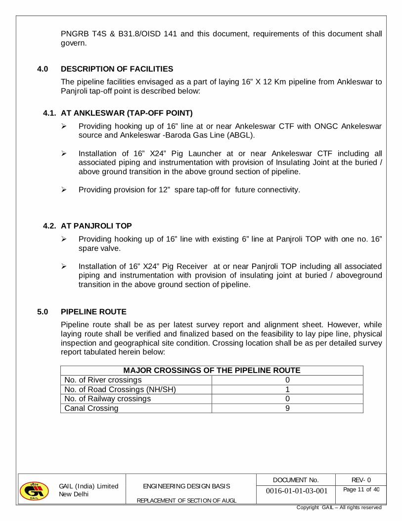
4.0 DESCRIPTION OF FACILITIES
The pipeline facilities envisaged as a part of laying 16” X 12 Km pipeline from Ankleswar to Panjroli tap-off point is described below:
4.1. AT ANKLESWAR (TAP-OFF POINT)
Providing hooking up of 16” line at or near Ankeleswar CTF with ONGC Ankeleswar source and Ankeleswar -Baroda Gas Line (ABGL).
Installation of 16” X24” Pig Launcher at or near Ankeleswar CTF including all associated piping and instrumentation with provision of Insulating Joint at the buried / above ground transition in the above ground section of pipeline.
Providing provision for 12” spare tap-off for future connectivity.
4.2. AT PANJROLI TOP
Providing hooking up of 16” line with existing 6” line at Panjroli TOP with one no. 16” spare valve.
Installation of 16” X24” Pig Receiver at or near Panjroli TOP including all associated piping and instrumentation with provision of insulating joint at buried / aboveground transition in the above ground section of pipeline.
5.0 PIPELINE ROUTE
Pipeline route shall be as per latest survey report and alignment sheet. However, while laying route shall be verified and finalized based on the feasibility to lay pipe line, physical inspection and geographical site condition. Crossing location shall be as per detailed survey report tabulated herein below:
MAJOR CROSSINGS OF THE PIPELINE ROUTENo. of River crossings 0No. of Road Crossings (NH/SH) 1No. of Railway crossings 0Canal Crossing 9

GAIL (India) Limited New Delhi
ENGINEERING DESIGN BASIS
REPLACEMENT OF SECTION OF AUGL
DOCUMENT No. REV- 0
0016-01-01-03-001 Page 12 of 40
Copyright GAIL – All rights reserved
6.0 DESIGN DATA
Pipeline shall be designed for conditions as follows:
PIPELINE DESIGN PARAMETERDescription Value
Pipeline line from Ankeleswar CTF with ONGC Ankeleswar source and Ankeleswar -Baroda Gas Line (ABGL).
16” OD
Product Natural Gas/R-LNG
Design Pressure 49 Kg/ Cm2g
Maximum Design Temperature, 0 C
i. Above Ground Section
ii. Under Ground Section
(-) 29 0C to 650 C
(-) 29 0C to 600 C
Corrosion Allowance for line pipe 0.5 mm
7.0 PIPELINE AND ASSOCIATED FACILITIES DESIGN
7.1 GENERAL
Pipeline and pipeline stations to be installed as a part of this project shall be designed and engineered in accordance with the standards/codes referred in section 3.0 of this document.
7.2 PIPELINE
7.2.1 Pipeline shall be designed in accordance with requirements of ASME B 31.8 and OISD 141. The pipeline shall withstand all installation, testing and operating condition/ loads. All necessary calculations shall be carried out to verify structural integrity and stability of the pipeline for the combined effect of pressure, temperature, bending (elastic), soil/pipe interaction, external loads and other environmental parameters as applicable during all phases of work from installation to operation. Allowable stress limit shall be as per ASME B 31.8. Such calculations shall include, but are not limited to following:
- Buoyancy control and stability analysis for pipeline section to be installed in areas subjected to flooding/submergence. Unless specified, specific gravity of installation in such area shall be at least 1.2.
- Stress analysis at crossing of major rivers, rails, highways etc.
- Crossing analysis of rivers by HDD if applicable.
- Pipeline expansion and its effect on station piping (above ground/under ground).
7.2.2 Pipeline shall also be checked for adequacy against anticipated earthquake loading and any

GAIL (India) Limited New Delhi
ENGINEERING DESIGN BASIS
REPLACEMENT OF SECTION OF AUGL
DOCUMENT No. REV- 0
0016-01-01-03-001 Page 13 of 40
Copyright GAIL – All rights reserved
special measures such as increase in wall thickness/ grade/ select backfill etc. as required to ensure safety and integrity of the pipeline system shall be implemented.
7.2.3 Pipeline and its associated facilities shall be designed using the applicable design code and as modified below.
The pipeline shall be designed to meet the Location Class as defined in ASME B31.8, except as modified below.
Location Class
Type of Facility Design Factor
All Station Piping 0.5
Class – 1 River / Stream Crossings Drilled / Bored/ Inaccessible / Open Cut 0.6 Others 0.72 HDD 0.5
Cased/Uncased Crossings or Parallel Encroachments on ROW of Hard Surfaced Roads, Public Streets and Highways
0.6
Railway Crossings 0.5
Class – 2 River / Stream Crossings Drilled / Bored/ Inaccessible / Open Cut 0.5 Others 0.6 HDD 0.5
Cased/Uncased Crossings or Parallel Encroachments on ROW of Hard Surfaced Roads, Public Streets and Highways
0.5
Railway Crossings 0.5
Class – 3 All 0.5
Class – 4 All 0.4
7.3 STATION PIPING
7.3.1 Station piping to be provided at terminals shall be designed in accordance with OISD 141/ASME B 31.8 and utility piping to be provided at these locations shall be designed in accordance with the provisions of ASME B 31.3.
7.3.2 All piping shall be designed for combined effects of pressure, weight and temperature during operating conditions without over stressing the piping, valves or equipment. All piping shall be adequately supported, guided or anchored so as to prevent undue vibration, deflection or loads on connected equipment such as filters, meters etc.
7.4 MATERIALS

GAIL (India) Limited New Delhi
ENGINEERING DESIGN BASIS
REPLACEMENT OF SECTION OF AUGL
DOCUMENT No. REV- 0
0016-01-01-03-001 Page 14 of 40
Copyright GAIL – All rights reserved
Pipeline and its appurtenances shall be provided with carbon steel materials suitable for the intended service, as detailed in subsequent paragraphs
7.4.1 LINE PIPE FOR MAIN LINE
Line pipe shall conform to API 5L and Company specifications. Type of line pipe to be used shall be LSAW/HSAW/EW/SEAMLESS. Line pipe shall be procured by GAIL and is a free issue material for the laying contractor. Following pipe size/classes/grade (or above) are applicable for laying in corresponding Class of location:
Sr. No. LINE SIZE GRADE Class - I Class - II1. 16” OD API-5L, PSL-2 Grade X-
65/ Grade X-60 6.4 6.4
Location class shall be as per survey report and alignment sheet.
7.4.2 OTHER MATERIALS
All other materials and equipments including insulating joints, ball valves, plug valves, globe valves, check valves flanges and fittings shall be carbon steel suitable for the service conditions and shall be compatible with the line pipe material.
7.5 EXTERNAL CORROSION COATING
7.5.1 Pipeline to be installed below ground shall be protected against external corrosion by a combination of high integrity externally applied coatings and permanent impressed cathodic protection system. Externally applied coating shall be 03 layers side extruded polyethylene coating. In addition 24” line is provided with minimum 80 micron thick liquid epoxy internal coating conforming to ISO 15741. Extremities of pipe shall be free from coating over a length of 20± 5mm.
7.5.2 All above ground piping and structures shall be painted to prevent atmospheric corrosion. Painting of above ground piping and structures shall be as per specifications. Painting shall be suitable for corrosive environment (saline climate) as defined in Painting Specification No. S-05-02-014 for all stations and terminals.
7.6 INSULATING JOINTS
Insulating joints shall be provided to electrically isolate the buried pipeline from the above ground pipeline. Insulating joints shall be monolithic type and shall allow smooth passage of pigs. Insulating joints shall be installed in the above ground portion of the pipeline, immediately after the buried / above ground transition at the scraper stations.
Wherever pressure/ temperature transmitters are used on cathodically protective pipeline the same shall be electrically isolated by providing insulating joints/ flanges.
7.7 PIPELINE BURIAL
The pipeline shall be buried normally at a depth of 1.0 meter below natural ground level except river/ rail/ road/ canal/waterways crossing where minimum cover shall be as given below or as per the requirements of statutory/local authorities whichever is more stringent.

GAIL (India) Limited New Delhi
ENGINEERING DESIGN BASIS
REPLACEMENT OF SECTION OF AUGL
DOCUMENT No. REV- 0
0016-01-01-03-001 Page 15 of 40
Copyright GAIL – All rights reserved
Increased cover shall be provided at critical locations and crossings.
Sl. Location Minimum Cover (m)
1.0 Industrial, commercial and residential area
1.0
2.0 Rocky terrain 1.0
3.0 Minor water crossing/ canal/ drain/ nala/ waterways
1.5
4.0 HDD crossing of canals (below bed) 2.5
5.0 River crossings for which scour depth is defined (below scour)
1.5
6.0
Other River crossings (Bank width >50m) (Below Bed) 2.5 (For normal soil)
1.5 (For rocky strata)
7.0 Other River crossings (Bank width < 50m) (Below Bed)
1.5
8.0 Cased/uncased road crossing 1.2
9.0 Cased railway crossing 1.7
10.0 Drainage, ditches at roads/railway crossings
1.2
11.0 Marshy land/Creek area 1.5
Additional soil cover other than specified above shall be provided at locations indicated by statutory/ local authorities or in areas likely to have an increased risk of impact damage or third party interference as per agreements between COMPANY and authorities. In case, any private dwelling, industrial building or place of public assembly falls within 15 m of pipeline, additional cover of minimum 300 mm shall be provided over and above the cover indicated in the above table.
7.8 MARSHY AREAS / AREAS PRONE TO FLOODING
Wherever marshy areas/areas prone to flooding are encountered along the pipeline route, pipeline shall be provided with anti buoyancy measures viz. continuous concrete coating/ Geotextile gravel filled bags. Unless specified otherwise in AFC drawings, specific gravity of installation in such areas shall be at least 1.2.
7.9 PIPELINE IN COMMON ROW
The location of new underground pipeline, when running parallel to an existing underground pipeline in same ROU/ROW shall be laid at minimum clear distance of 5.0 m from the existing underground pipeline. This distance may be reduced to 3.0 m after assessment of construction methodology which does not result in unsafe conditions during construction, with prior approval from GAIL.
GAIL (India) Limited New Delhi
ENGINEERING DESIGN BASIS
REPLACEMENT OF SECTION OF AUGL
DOCUMENT No. REV- 0
0016-01-01-03-001 Page 16 of 40
Copyright GAIL – All rights reserved
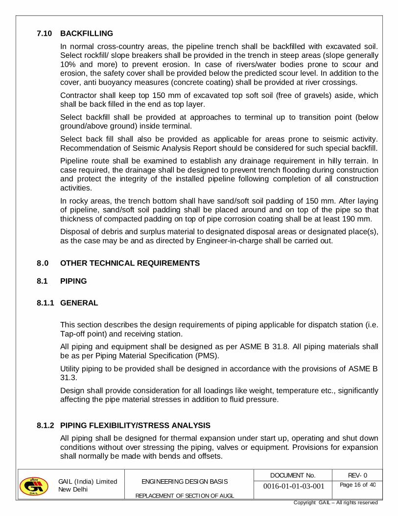
7.10 BACKFILLING
In normal cross-country areas, the pipeline trench shall be backfilled with excavated soil. Select rockfill/ slope breakers shall be provided in the trench in steep areas (slope generally 10% and more) to prevent erosion. In case of rivers/water bodies prone to scour and erosion, the safety cover shall be provided below the predicted scour level. In addition to the cover, anti buoyancy measures (concrete coating) shall be provided at river crossings.
Contractor shall keep top 150 mm of excavated top soft soil (free of gravels) aside, which shall be back filled in the end as top layer.
Select backfill shall be provided at approaches to terminal up to transition point (below ground/above ground) inside terminal.
Select back fill shall also be provided as applicable for areas prone to seismic activity. Recommendation of Seismic Analysis Report should be considered for such special backfill.
Pipeline route shall be examined to establish any drainage requirement in hilly terrain. In case required, the drainage shall be designed to prevent trench flooding during construction and protect the integrity of the installed pipeline following completion of all construction activities.
In rocky areas, the trench bottom shall have sand/soft soil padding of 150 mm. After laying of pipeline, sand/soft soil padding shall be placed around and on top of the pipe so that thickness of compacted padding on top of pipe corrosion coating shall be at least 190 mm.
Disposal of debris and surplus material to designated disposal areas or designated place(s), as the case may be and as directed by Engineer-in-charge shall be carried out.
8.0 OTHER TECHNICAL REQUIREMENTS
8.1 PIPING
8.1.1 GENERAL
This section describes the design requirements of piping applicable for dispatch station (i.e. Tap-off point) and receiving station.
All piping and equipment shall be designed as per ASME B 31.8. All piping materials shall be as per Piping Material Specification (PMS).
Utility piping to be provided shall be designed in accordance with the provisions of ASME B 31.3.
Design shall provide consideration for all loadings like weight, temperature etc., significantly affecting the pipe material stresses in addition to fluid pressure.
8.1.2 PIPING FLEXIBILITY/STRESS ANALYSIS
All piping shall be designed for thermal expansion under start up, operating and shut down conditions without over stressing the piping, valves or equipment. Provisions for expansion shall normally be made with bends and offsets.
GAIL (India) Limited New Delhi
ENGINEERING DESIGN BASIS
REPLACEMENT OF SECTION OF AUGL
DOCUMENT No. REV- 0
0016-01-01-03-001 Page 17 of 40
Copyright GAIL – All rights reserved
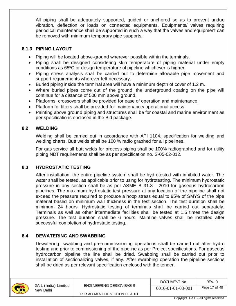
All piping shall be adequately supported, guided or anchored so as to prevent undue vibration, deflection or loads on connected equipments. Equipments/ valves requiring periodical maintenance shall be supported in such a way that the valves and equipment can be removed with minimum temporary pipe supports.
8.1.3 PIPING LAYOUT
Piping will be located above-ground wherever possible within the terminals. Piping shall be designed considering skin temperature of piping material under empty
conditions as 65ºC or design temperature of pipeline whichever is higher. Piping stress analysis shall be carried out to determine allowable pipe movement and
support requirements wherever felt necessary. Buried piping inside the terminal area will have a minimum depth of cover of 1.2 m. Where buried pipes come out of the ground, the underground coating on the pipe will
continue for a distance of 500 mm above ground. Platforms, crossovers shall be provided for ease of operation and maintenance. Platform for filters shall be provided for maintenance/ operational access. Painting above ground piping and structures shall be for coastal and marine environment as
per specifications enclosed in the Bid package.
8.2 WELDING
Welding shall be carried out in accordance with API 1104, specification for welding and welding charts. Butt welds shall be 100 % radio graphed for all pipelines.
For gas service all butt welds for process piping shall be 100% radiographed and for utility piping NDT requirements shall be as per specification no. S-05-02-012.
8.3 HYDROSTATIC TESTING
After installation, the entire pipeline system shall be hydrotested with inhibited water. The water shall be tested, as applicable prior to using for hydrotesting. The minimum hydrostatic pressure in any section shall be as per ASME B 31.8 - 2010 for gaseous hydrocarbon pipelines. The maximum hydrostatic test pressure at any location of the pipeline shall not exceed the pressure required to produce a hoop stress equal to 95% of SMYS of the pipe material based on minimum wall thickness in the test section. The test duration shall be minimum 24 hours. Hydrostatic testing of terminals shall be carried out separately. Terminals as well as other intermediate facilities shall be tested at 1.5 times the design pressure. The test duration shall be 6 hours. Mainline valves shall be installed after successful completion of hydrostatic testing.
8.4 DEWATERING AND SWABBING
Dewatering, swabbing and pre-commissioning operations shall be carried out after hydro testing and prior to commissioning of the pipeline as per Project specifications. For gaseous hydrocarbon pipeline the line shall be dried. Swabbing shall be carried out prior to installation of sectionalizing valves, if any. After swabbing operation the pipeline sections shall be dried as per relevant specification enclosed with the tender.

GAIL (India) Limited New Delhi
ENGINEERING DESIGN BASIS
REPLACEMENT OF SECTION OF AUGL
DOCUMENT No. REV- 0
0016-01-01-03-001 Page 18 of 40
Copyright GAIL – All rights reserved
8.5 CROSSINGS
8.5.1 WATER CROSSINGS
All water crossing shall be installed by open cut. The requirement of HDD at any water crossing shall be finalized during detailed engineering.
Wherever there is an evidence of bank erosion, the banks shall be protected by using gravel and boulders filled embankment mattresses of galvanized iron wire to be laid over the backfilled, compacted and graded banks.
8.5.2 RAIL CROSSING
Pipeline at rail crossings shall be provided with casing pipe. The casing pipe shall be three nominal pipe sizes larger than carrier pipe (unless advised otherwise by concerned authorities) and shall be installed by boring/ jacking/ HDD/ ramming. The rail crossing shall comply with the requirements of API 1102 and Indian Railway Authorities. The crossing angle shall be as close to 90º as possible. It should be noted that the extent of casing pipe generally specified by Railways is 14.0 m beyond centerline of the outermost tracks on either side or 0.6 meter beyond the ROU limits of Railways on either side, whichever is more. Carrier pipe shall be electrically insulated from the casing pipe and casing ends shall be sealed using durable, electrically non-conducting materials. The crossing drawing shall be subject to approval of concerned Railway Authorities prior to implementation.
8.5.3 ROAD CROSSING
Road crossings shall comply with the requirements of API 1102 and the requirements of the concerned road authorities. Unless otherwise required by concerned Authorities, casing pipe shall not be used. However at national highway road crossings pipeline shall be provided with casing pipe, which shall extend min. 600 mm beyond Road ROW on either side. The casing pipe shall be installed by trenchless method like ramming/ boring/ jacking/ HDD /Micro Tunelling. Provision of casing at locations other than national highways shall be decided based on type of road crossing and as per requirements of local authorities if necessary. The casing pipe shall be three nominal pipe size larger than the casing pipe. The crossing angle shall be as close to 90º as possible. Casing insulators and end seals shall be provided to ensure electrical isolation of carrier pipe and casing pipe.
8.5.4 EXISTING PIPELINE CROSSING
The specific requirements of Owner/operator of existing pipeline shall generally be followed. The minimum clearance between the lines shall be 300 mm unless specified otherwise.
8.6 VALVES
8.6.1 APPLICATION OF VARIOUS TYPES OF VALVES SHALL BE AS FOLLOWS:
Valve type Typical application
Globe Throttling
GAIL (India) Limited New Delhi
ENGINEERING DESIGN BASIS
REPLACEMENT OF SECTION OF AUGL
DOCUMENT No. REV- 0
0016-01-01-03-001 Page 19 of 40
Copyright GAIL – All rights reserved
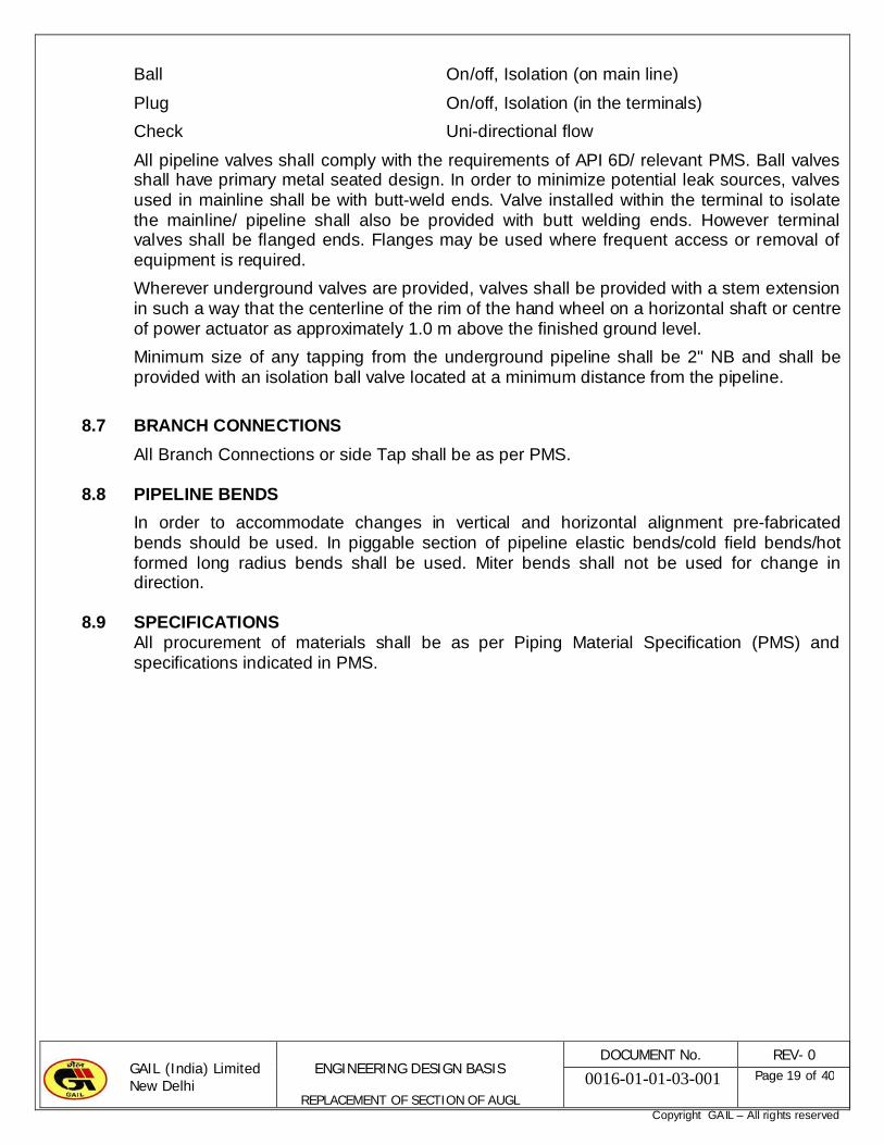
Ball On/off, Isolation (on main line)
Plug On/off, Isolation (in the terminals)
Check Uni-directional flow
All pipeline valves shall comply with the requirements of API 6D/ relevant PMS. Ball valves shall have primary metal seated design. In order to minimize potential leak sources, valves used in mainline shall be with butt-weld ends. Valve installed within the terminal to isolate the mainline/ pipeline shall also be provided with butt welding ends. However terminal valves shall be flanged ends. Flanges may be used where frequent access or removal of equipment is required.
Wherever underground valves are provided, valves shall be provided with a stem extension in such a way that the centerline of the rim of the hand wheel on a horizontal shaft or centre of power actuator as approximately 1.0 m above the finished ground level.
Minimum size of any tapping from the underground pipeline shall be 2" NB and shall be provided with an isolation ball valve located at a minimum distance from the pipeline.
8.7 BRANCH CONNECTIONS
All Branch Connections or side Tap shall be as per PMS.
8.8 PIPELINE BENDS
In order to accommodate changes in vertical and horizontal alignment pre-fabricated bends should be used. In piggable section of pipeline elastic bends/cold field bends/hot formed long radius bends shall be used. Miter bends shall not be used for change in direction.
8.9 SPECIFICATIONS All procurement of materials shall be as per Piping Material Specification (PMS) and specifications indicated in PMS.

GAIL (India) Limited New Delhi
ENGINEERING DESIGN BASIS
REPLACEMENT OF SECTION OF AUGL
DOCUMENT No. REV- 0
0016-01-01-03-001 Page 20 of 40
Copyright GAIL – All rights reserved
ANNEXURE - A LIST OF CODES AND STANDARDS
In addition to the codes/standards mentioned in para 3.0, the latest edition of the below listed equivalent codes and standards shall also be used for design of proposed pipeline. The listing includes, but is not limited to, the following:
1. Line Pipes
API 5L Specification for Line pipe API 5L1 Recommended Practice for Railroad
Transportation of Line pipe API 5LW Recommended Practice for Transportation
of Line pipe on Barges & Marine Vessels
2. Valves API 6D Specification for pipeline valves (Steel
Gate, Plug, Ball and Check Valves)
API 602 Compact Steel Gate Valves-Flanged, Threaded, Welding & Extended Body ends.
ASTM A694 Forgings, Carbon & Alloy steel for Pipe Flanges, Fittings, Valves & parts for High Pressure Transmission Service.
MSS-SP-6 Finishes for Contact Faces of connecting End Flanges of Ferrous Valves and Fittings.
MSS-SP-25 Standard Marking System for Valves, Fittings & Unions
BS 533.61 Steel Ball Valves for the Petroleum, Petrochemical and Allied Industries
3. Flanges & Fittings
MSS-SP-44 Steel Pipeline Flanges
ANSI B16.5 Pipe Flanges and Flanged Fittings
ANSI 16.20 Ring-joint Gaskets & Grooves for Steel Pipe Flanges
ASTM A105 Forgings, Carbon Steel for Piping Components
ASTM A193 Carbon & Alloy Steel Bolts & Studs for High Temperature Service
API 601 Standard for Metallic Gaskets for Raised-Face Pipe Flanges & Flanged Connections
ANSI B16.9 Factory Made Wrought Steel Butt Welding Fittings
ANSI B16.11 Forged Fittings, Socket Welded & Threaded

GAIL (India) Limited New Delhi
ENGINEERING DESIGN BASIS
REPLACEMENT OF SECTION OF AUGL
DOCUMENT No. REV- 0
0016-01-01-03-001 Page 21 of 40
Copyright GAIL – All rights reserved
ANSI B16.26 Butt Welding Ends ASTM A234 Piping Fittings of Wrought Carbon Steel
and Alloy Steel for Moderate and Elevated Temperatures
ASTM A694 Forgings, Carbon & Alloy Steel for Pipe Flanges, Fittings, Valves & Parts for High Pressure Transmission Service.
MSS-SP-75 Specification for High Test Wrought Butt Welding Fittings
MSS-SP-97 Integrally Reinforced Forced Branch Outley Fittings – Socket Welding, Threaded and Butt Welding Ends.
PFI-ES-24 Pipe Bending Methods, Tolerances, Processes & Material Requirements
4. Testing & Welding ANSI/AWS D1.1 Structural Steel Welding
API 1104 Standard for Welding Pipelines andRelated Facilities
AWS A3.0 Welding Terms and Definitions
AWS A5.1 Welding Electrodes
AWS A5.5 Specification for Low Alloy Steel Covered Arc Welding Electrodes
ASTM E165 Liquid Dye Penetrant Inspection of Pipeline Welds
ASTM A370 Standard Methods and Definitions for Mechanical Testing of Steel Products.
ASTM E18 Standard Hardness Test for Metals
ASTM E23 Standard for Impact Test for Metals
ASTM E84 Standard Test Method for Micro-hardness of Metals
ASTM E92 Standard Test Method for Vickers Hardness of Metallic Materials
ASTM E110 Standard Test Method Indentation Hardness for Metallic Materials by Portable Hardness Testers
ASTM E709 Standard Guides for Magnetic Particle Examination
MSS-SP-53 Quality Standard for Steel Casting & Forging-Magnetic Particle Method
MSS-SP-54 Quality Standard for Steel Casting & Forging-Radiographic Examination
MSS-SP-55 Quality Standard for Steel Castings & Forgings-Visual Method.

GAIL (India) Limited New Delhi
ENGINEERING DESIGN BASIS
REPLACEMENT OF SECTION OF AUGL
DOCUMENT No. REV- 0
0016-01-01-03-001 Page 22 of 40
Copyright GAIL – All rights reserved
5. Surface Preparation, Painting and Coating
SIS-05-59 Pictorial Surface Preparation Standards for Painting Steel Surfaces
SSPC-SP-01 Solvent Cleaning
SSPC-SP-03 Power Tool Cleaning
SSPC-SP-05 Joint Surface Preparation Standard: White Metal Blast Cleaning
SSPC-SP10 Structural Steel Painting Council – Joint Surface
NACE No.2 Preparation Standard - Near-White Metal Blast Cleaning
SSPC-PA-02 Measurement of Dry Paint Thickness and Magnetic Gauges
ASTM E12 Measurement of Pipeline Dry Film Coating Thickness
ASTM-G6 Abrasion Resistance of Pipeline Coating
ASTM G8 Cathodic Disbonding of Pipeline Coatings
NACE-RP-0274High Voltage Electrical Inspection of Pipeline Coatings Prior to Installation
IEC 454 – 2
Specification for Pressure-Sensitive Adhesive Tapes for Electrical Purposes CSA Z245.20-02 External Fusion Bond Epoxy Coating for Steel Pipe.
6. Safety Systems
IP Model Code of Safe Practice in the Petroleum Industry parts 3, 6 and 9 shall be followed.


GAIL (India) Limited New Delhi
ENGINEERING DESIGN BASIS
REPLACEMENT OF SECTION OF AUGL
DOCUMENT No. REV- 0
0016-01-01-03-001 Page 36 of 40
Copyright GAIL – All rights reserved
CONTENTS
1. SITE CONDITIONS
2. POWER SOURCE DETAILS
3. UTILISATION VOLTAGE & OPERATING PHILOSOPHY
4. CONTROL BUILDING DESIGN
5. EQUIPMENT DESIGN
6. CABLING SYSTEM
7. EARTHING SYSTEM
8. LIGHTING AND VENTILATION SYSTEM
9. ELECTRICAL EQUIPMENT FOR HAZARDOUS AREAS
10. STATUTORY APPROVALS
11. CATHODIC PROTECTION SYSTEM
GAIL (India) Limited New Delhi
ENGINEERING DESIGN BASIS
REPLACEMENT OF SECTION OF AUGL
DOCUMENT No. REV- 0
0016-01-01-03-001 Page 37 of 40
Copyright GAIL – All rights reserved
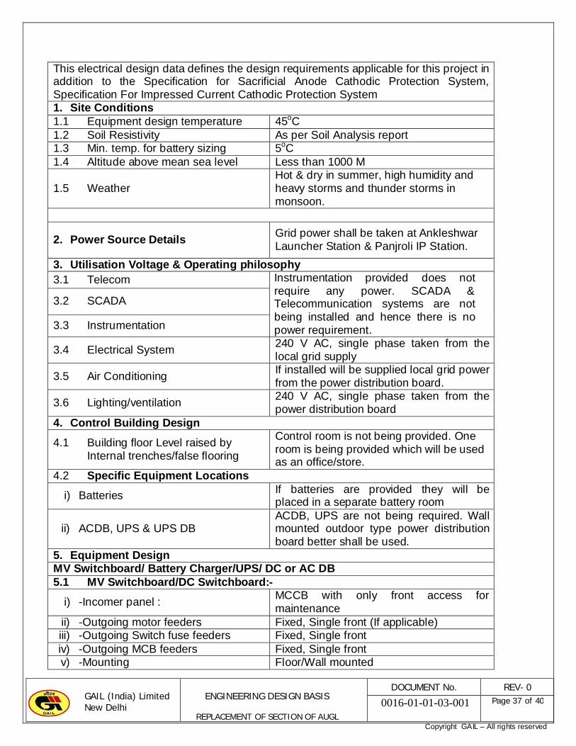
This electrical design data defines the design requirements applicable for this project in addition to the Specification for Sacrificial Anode Cathodic Protection System, Specification For Impressed Current Cathodic Protection System 1. Site Conditions1.1 Equipment design temperature 45oC1.2 Soil Resistivity As per Soil Analysis report1.3 Min. temp. for battery sizing 5oC1.4 Altitude above mean sea level Less than 1000 M
1.5 WeatherHot & dry in summer, high humidity and heavy storms and thunder storms in monsoon.
2. Power Source DetailsGrid power shall be taken at Ankleshwar Launcher Station & Panjroli IP Station.
3. Utilisation Voltage & Operating philosophy3.1 Telecom Instrumentation provided does not
require any power. SCADA & Telecommunication systems are not being installed and hence there is no power requirement.
3.2 SCADA
3.3 Instrumentation
3.4 Electrical System240 V AC, single phase taken from the local grid supply
3.5 Air ConditioningIf installed will be supplied local grid power from the power distribution board.
3.6 Lighting/ventilation240 V AC, single phase taken from the power distribution board
4. Control Building Design
4.1 Building floor Level raised by Internal trenches/false flooring
Control room is not being provided. One room is being provided which will be used as an office/store.
4.2 Specific Equipment Locations
i) Batteries If batteries are provided they will be placed in a separate battery room
ii) ACDB, UPS & UPS DBACDB, UPS are not being required. Wall mounted outdoor type power distribution board better shall be used.
5. Equipment DesignMV Switchboard/ Battery Charger/UPS/ DC or AC DB5.1 MV Switchboard/DC Switchboard:-
i) -Incomer panel :MCCB with only front access for maintenance
ii) -Outgoing motor feeders Fixed, Single front (If applicable)iii) -Outgoing Switch fuse feeders Fixed, Single frontiv) -Outgoing MCB feeders Fixed, Single frontv) -Mounting Floor/Wall mounted

GAIL (India) Limited New Delhi
ENGINEERING DESIGN BASIS
REPLACEMENT OF SECTION OF AUGL
DOCUMENT No. REV- 0
0016-01-01-03-001 Page 38 of 40
Copyright GAIL – All rights reserved
5.2 Lighting Panel Floor/Wall mounted5.3 Back-up battery5.3.1 Battery type/back up time Not applicable 5.3.2 Battery execution Not applicable 5.3.3 DC to DC converters Not applicable 5.3.4 AC to DC converters Not applicable5.4 Cables for Electrical System
5.4.1 TypePVC insulated armoured, PVC sheathed for MV cable and XLPE insulated, armored, PVC sheathed for HV cable
5.4.2 Conductor materialCopper up to 16 sq mm and Aluminium for 35 sq mm and above.
5.4.3 Minimum size of cable for power and control cables5.4.3.1 Medium voltage power cable 2.5 mm² (Copper)5.4.3.2 Control cables 2.5 mm² (Copper)5.4.3.3 Lighting 2.5 mm² (Copper)6. Cabling System6.1 Cable laying philosophy6..1.1 Paved area Cable tray / RCC trench6..1.2 Unpaved area RCC trench / Directly buried6..1.3 Inside Buildings Cable trays / conduits/RCC Trench
6..1.4 Type of cable trays Galvanized prefabricated / Site fabricated And painted
7. Earthing System
7.1 Number of earthing system
Separate systems (one each for Electrical general & safety earth,, Instruments + Scada / Telecom systems), comprising of at least two earth electrodes each
7.2 Earth electrode GI Pipe/plate7.3 Main earth loop material GI strip7.4 Control building earth loop GI8. Lighting and Ventilation System8.1 Lighting Control Philosophy Indoor Manual 8.1.1 Outdoor Manual 8.1.2 Lighting cum Power Panel control
elementMCB
8.1.3 ELCB at Incomer of AC Lighting cum Power Panels
Yes for AC
8.2 Wiring Type8.2.1 Out door Armoured cable
8.2.2 BuildingsConcealed conduit below false ceiling and Surface conduits or cable trays above false ceiling
8.3 Ventilation8.3.1 Battery room Not applicable8.3.2 SCADA/Telecom room/Control
RoomNot applicable

GAIL (India) Limited New Delhi
ENGINEERING DESIGN BASIS
REPLACEMENT OF SECTION OF AUGL
DOCUMENT No. REV- 0
0016-01-01-03-001 Page 39 of 40
Copyright GAIL – All rights reserved
8.3.3 Electrical room Not applicable8.4Lighting System DesignLighting design shall conform to relevant Indian and International Codes and Standards, IES Hand Book and shall take into consideration the requirements from point of view of safety and ease in operation and maintenance. A maintenance factor of 0.8 shall be assumed for lighting illumination level calculations for normal areas. However for dusty areas, maintenance factor as per relevant codes and standards shall be considered. Lighting system design shall be based on illumination levels as specified below:Area Lux LevelControl room, Laboratory 500Office 300Battery Room 150Electrical Equipment room 150Process Area, Pipe Racks rtc. 60Main Operation Areas/Platforms 60Roads 209. Electrical Equipment for Hazardous AreasAll the electrical equipment for Gas Group IIA/ IIB hazardous areas shall be of Ex-d type suitable for temp classification T3.10.Statutory ApprovalStatutory Authority for Electrical: Central Electrical Inspectorate/State Installation electrical inspectorate.11.CP System11.1 Temporary cathodic protection Required 11.1.1 Type Sacrificial magnesium anode
11.1.2 Design life 1 Year or till commissioning of PCP whichever is later
11.1.3 Pipeline coating Three Layer Polyethylene11.1.4 Protective current density As per specification11.1.5 Anode material Zinc/ low potential (1.55 V ) Magnesium11.1.6 Polarisation coupons Shall be provided as per specification
(i) Size of exposed area of coupon 100mm x 100mm
(ii) No. of couponsTo be decided by CP contractor based on specification
(iii) No. of magnet devices for operation of magnetic reed switch
By CP contractor
(iv) Polarisation cell Solid state type(v) Additional tests to evaluate the
coating defectsShall be conducted
11.2 Permanent Cathodic Protection System11.2.1 Type Impressed current type11.2.2 TR Unit Shall be provide at Panjroli IP Station11.2.3 Design life of protection 25 Years11.2.4 Design protection current density As per specification11.2.5 Current drainage survey Shall be carried out11.2.6 Type of Anodes for anode ground High silicon iron / mixed metal oxide

GAIL (India) Limited New Delhi
ENGINEERING DESIGN BASIS
REPLACEMENT OF SECTION OF AUGL
DOCUMENT No. REV- 0
0016-01-01-03-001 Page 40 of 40
Copyright GAIL – All rights reserved
bed titanium/ Zinc/Magnesium11.2.7 Polarization coupons Shall be provided if required11.2.8 Polarization cell Shall be provided if required11.2.9 Acquisition of land for anode
ground bed, anode junction boxes and anode ground bed cable laying
Deep well anode bed shall preferable be provided wiyhin the IP Station. Necessary calculations for checking the remoteness of the pipeline from the anode bed shall be carried out by the contractor. In case the pipe is not sufficiently remote (anode voltage at pipe to be less that 5%) land for the anode bed shall be acquired outside the IP Station area. Soil resistivity survey for anode bed shall also be carried out the contractor.
11.2.10 Chain link fencing around the ground bed
Shall be provided

Copyright GAIL – All rights reserved
PIPING & INSTRUMENTATION DIAGRAMS
REPLACEMENTOF
SECTION OF ANKALESHWAR- UTARAN GAS LINE, AUGL

Copyright GAIL – All rights reserved
INDEX
Sl.No. DESCRIPTION
1 P&ID LEGENDS (Sheet 1 OF 2)
2 P&ID LEGENDS (Sheet 2 OF 2)
3 AV DETAIL-A (Typical)
4 Pig Launcher/ Receiver at Ankleshwar CTF
5 Pig Launcher/ Receiver at Panjroli


