58
CELERITIVE TECHNOLOGIES, INC. VOLUMILL ™ UNIVERSAL REFERENCE GUIDE

CELERITIVE TECHNOLOGIES, INC.
VOLUMILL™ UNIVERSAL
REFERENCE GUIDE

VoluMill Universal

VoluMill Universal
Reference Guide 8/30/2010

ii | P a g e
VOLUMILL™ Universal Reference Guide
Date: August 2010
Copyright© 2010 Celeritive Technologies, Inc. All rights reserved.
Software: VoluMill Universal v3.5
IMPORTANT NOTICE!
The accompanying executable code version of VoluMill™ and related documentation (the "Product")
is made available to you under the terms of this VOLUMILL™ END-USER SOFTWARE LICENSE
AGREEMENT (THE "AGREEMENT"). BY CLICKING THE "ACCEPT" BUTTON, OR BY
INSTALLING OR USING THE PRODUCT, YOU ARE CONSENTING TO BE BOUND BY THE
AGREEMENT. IF YOU DO NOT AGREE TO THE TERMS AND CONDITIONS OF THIS
AGREEMENT, DO NOT CLICK THE "ACCEPT" BUTTON, AND DO NOT INSTALL OR USE
ANY PART OF THE PRODUCT.
LICENSE GRANT
Celeritive Technologies, Inc. ("Celeritive") grants you a non-exclusive license to use the executable
code version of the Product. This Agreement will also govern any software upgrades provided by
Celeritive that replace and/or supplement the original Product, unless such upgrades are accompanied
by a separate license, in which case the terms of that license will govern.
TERMINATION
If you breach this Agreement your right to use the Product will terminate immediately and without
notice, but all provisions of this Agreement except the License Grant (Paragraph 1) will survive
termination and continue in effect. Upon termination, you must destroy all copies of the Product.
PROPRIETARY RIGHTS
Portions of the Product are available in source code form under the terms of the GNU Lesser General
Public License, Apache Software License, and other open source licenses (collectively, "Open Source
Licenses") at http://www.celeritive.com. Nothing in this Agreement will be construed to limit any
rights granted under the Open Source Licenses. Subject to the foregoing, Celeritive Technologies, for
itself and on behalf of its licensors, hereby reserves all intellectual property rights in the Product,
except for the rights expressly granted in this Agreement. You may not remove or alter any
trademark, logo, copyright or other proprietary notice in or on the Product. This license does not grant
you any right to use the trademarks, service marks or logos of Celeritive Technologies or its licensors.
DISCLAIMER OF WARRANTY
THE PRODUCT IS PROVIDED "AS IS" WITH ALL FAULTS. TO THE EXTENT PERMITTED
BY LAW, CELERITIVE TECHNOLOGIES AND CELERITIVE'S DISTRIBUTORS AND
LICENSORS HEREBY DISCLAIM ALL WARRANTIES, WHETHER EXPRESS OR IMPLIED,
INCLUDING WITHOUT LIMITATION WARRANTIES THAT THE PRODUCT IS FREE OF
DEFECTS, MERCHANTABLE, FIT FOR A PARTICULAR PURPOSE AND NON-INFRINGING.
YOU BEAR ENTIRE RISK AS TO SELECTING THE PRODUCT FOR YOUR PURPOSES AND
AS TO THE QUALITY AND PERFORMANCE OF THE PRODUCT. THIS LIMITATION WILL
APPLY NOTWITHSTANDING THE FAILURE OF ESSENTIAL PURPOSE OF ANY REMEDY.
SOME JURISDICTIONS DO NOT ALLOW THE EXCLUSION OR LIMITATION OF IMPLIED
WARRANTIES, SO THIS DISCLAIMER MAY NOT APPLY TO YOU.

iii | P a g e
LIMITATION OF LIABILITY
EXCEPT AS REQUIRED BY LAW, CELERITIVE TECHNOLOGIES AND ITS DISTRIBUTORS,
DIRECTORS, LICENSORS, CONTRIBUTORS AND AGENTS (COLLECTIVELY, THE
"CELERITIVE GROUP") WILL NOT BE LIABLE FOR ANY INDIRECT, SPECIAL,
INCIDENTAL, CONSEQUENTIAL OR EXEMPLARY DAMAGES ARISING OUT OF OR IN
ANY WAY RELATING TO THIS AGREEMENT OR THE USE OF OR INABILITY TO USE THE
PRODUCT, INCLUDING WITHOUT LIMITATION DAMAGES FOR LOSS OF GOODWILL,
WORK STOPPAGE, LOST PROFITS, LOSS OF DATA, AND COMPUTER FAILURE OR
MALFUNCTION, EVEN IF ADVISED OF THE POSSIBILITY OF SUCH DAMAGES AND
REGARDLESS OF THE THEORY (CONTRACT, TORT OR OTHERWISE) UPON WHICH
SUCH CLAIM IS BASED. THE CELERITIVE GROUP'S COLLECTIVE LIABILITY UNDER
THIS AGREEMENT WILL NOT EXCEED THE GREATER OF $500 (FIVE HUNDRED
DOLLARS) AND THE FEES PAID BY YOU UNDER THIS LICENSE (IF ANY). SOME
JURISDICTIONS DO NOT ALLOW THE EXCLUSION OR LIMITATION OF INCIDENTAL,
CONSEQUENTIAL OR SPECIAL DAMAGES, SO THIS EXCLUSION AND LIMITATION MAY
NOT APPLY TO YOU.
EXPORT CONTROLS
This license is subject to all applicable export restrictions. You must comply with all export and
import laws and restrictions and regulations of any United States or foreign agency or authority
relating to the Product and its use.
U.S. GOVERNMENT END-USERS
The Product is a "commercial item," as that term is defined in 48 C.F.R. 2.101, consisting of
"commercial computer software" and "commercial computer software documentation," as such terms
are used in 48 C.F.R. 12.212 (Sept. 1995) and 48 C.F.R. 227.7202 (June 1995). Consistent with 48
C.F.R. 12.212, 48 C.F.R. 27.405(b)(2) (June 1998) and 48 C.F.R. 227.7202, all U.S. Government End
Users acquire the Product with only those rights as set forth herein.
MISCELLANEOUS
(a) This Agreement constitutes the entire agreement between Celeritive and you concerning the
subject matter hereof, and it may only be modified by a written amendment signed by an authorized
executive of Celeritive. (b) Except to the extent applicable law, if any, provides otherwise, this
Agreement will be governed by the laws of the state of Arizona, U.S.A., excluding its conflict of law
provisions. (c) This Agreement will not be governed by the United Nations Convention on Contracts
for the International Sale of Goods. (d) If any part of this Agreement is held invalid or unenforceable,
that part will be construed to reflect the parties' original intent, and the remaining portions will remain
in full force and effect. (e) A waiver by either party of any term or condition of this Agreement or any
breach thereof, in any one instance, will not waive such term or condition or any subsequent breach
thereof. (f) Except as required by law, the controlling language of this Agreement is English. (g) You
may assign your rights under this Agreement to any party that consents to, and agrees to be bound by,
its terms; Celeritive Technologies, Inc. may assign its rights under this Agreement without condition.
(h) This Agreement will be binding upon and will inure to the benefit of the parties, their successors
and permitted assigns.
THIRD PARTY SOFTWARE
This Product includes software developed by the OpenSSL Project for use in the OpenSSL Toolkit
(http://www.openssl.org/). This Product includes cryptographic software written by Eric Young
([email protected]). By using the Product, you agree to be bound by the licenses of these Third
Party products. These Third Party licenses are attached here for your reference.

iv | P a g e
CONTENTS Introduction ............................................................................................................................................ 1
Installation.......................................................................................................................................... 2
Licensing ............................................................................................................................................ 4
Technical Support .............................................................................................................................. 4
Tutorials ................................................................................................................................................. 5
Programming a 2-axis Part ................................................................................................................. 5
Programming a 3-axis Part ............................................................................................................... 11
User Interface ....................................................................................................................................... 17
Menus ............................................................................................................................................... 17
File ............................................................................................................................................... 17
Edit ............................................................................................................................................... 18
View ............................................................................................................................................. 18
Create ........................................................................................................................................... 18
Toolbars ........................................................................................................................................... 19
Main ............................................................................................................................................. 19
View ............................................................................................................................................. 19
Toolpath ....................................................................................................................................... 20
Tools ............................................................................................................................................ 20
Select ............................................................................................................................................ 21
Coordinate Systems ......................................................................................................................... 22
Toolpath Manager ............................................................................................................................ 24
Workspace........................................................................................................................................ 27
Right-click .................................................................................................................................... 27
Chaining ........................................................................................................................................... 27
Units ................................................................................................................................................. 28
2-axis Parameters ................................................................................................................................. 29
3-Axis Parameters ................................................................................................................................ 37
Post Processing .................................................................................................................................... 47
Post Processor Files ..................................................................................................................... 47
Post Processor Formatting ........................................................................................................... 47
Troubleshooting ................................................................................................................................... 51

1 | P a g e
Chapter 1
INTRODUCTION This chapter covers the following topics:
Installation
Licensing
Technical Support
Welcome to the VoluMill™ Universal Reference Guide. This guide is designed to provide all the
information possible in using VoluMill Universal to complement your current CAD/CAM system.
This guide can be used to jump right into using the software or it can be read cover-to-cover.
VoluMill Universal is a stand-alone system capable of creating VoluMill toolpaths on wireframe
geometry and surface models generated from your CAD/CAM system. VoluMill is an ultra
high‐performance technology developed by Celeritive Technologies, Inc. to be used in place of
traditional roughing methods when reducing cycle times, extending tool life, and reducing the stress
on machine tools is a priority. A VoluMill toolpath is designed to never exceed a defined Material
Removal Rate during the entire program. See www.volumill.com for more information on the
engine and its toolpath.
A license is required to use VoluMill. To purchase VoluMill Universal, please contact your local
authorized VoluMill reseller or Celeritive Technologies directly through our website,
www.volumill.com, call us at (888) 253-6701, or email [email protected].

2 | P a g e
Installation VoluMill is available as a download from the Celeritive Technologies website.
To download and install VoluMill:
1) Go to www.volumill.com, and then select Product Downloads from the Support menu:
2) Locate VoluMill Universal, then push the Download button:
A dialog will appear asking you to either run or save the file. If you select Run, the software
will be downloaded into your computer’s temporary folder and the installation program will
begin automatically.
If you select Save, you will be prompted for a location on your computer to save the software
to. Once it’s finished downloading, you’ll need to navigate to the location the file was saved
to and either double-click, or right-click on the file and select Run.

3 | P a g e
3) The installation Wizard will open and step you through the process.

4 | P a g e
Licensing In order to use VoluMill you must have an activated license.
Please refer to the VoluMill Licensing Guide for information on how to install and activate
licenses. It can be found in the VoluMill Universal program group.
Technical Support Our Technical Support department is available to answer your questions Monday through Friday,
8:00 AM to 5:00 PM, Pacific Standard Time. Technical Support is available to all users on
maintenance.
Celeritive Technologies maintains a permanent presence on the World Wide Web:
The Celeritive Technologies web site contains company news, product information, email links,
user forums and much more. It is the preferred means of connecting to Celeritive Technologies
electronically. The Celeritive Technologies website is located at www.celeritive.com or
www.volumill.com.
The Celeritive website provides a support page to report any difficulties found while using
VoluMill. To access the support section of the website, select Bug Reports from the Support menu:
www.celeritive.com/bugreport.htm. Alternatively, you may email support directly. If you need to
send a file, please include it as an attachment. When sending files, it is extremely helpful to include
a contact name and phone number and a brief description of any issues. To send email to support,
use: [email protected].

5 | P a g e
Chapter 2
TUTORIALS The following tutorials provide step-by-step instructions on how to effectively use VoluMill
Universal.
Example Feed Rates, Spindle Speeds, etc., are used as possible values. Your setup, tooling,
material, machine tool, etc., will need to be considered when programming actual parts.
Examples of actual values used in testing and from customer experiences are available from the
VoluMill website: www.celeritive.com.
Programming a 2-axis Part What you will learn…
How to create a 2-Axis VoluMill toolpath from a DXF file
How to use the chaining options to define open edges of a pocket
How spindle speeds and feed rates apply to VoluMill
How to backplot a toolpath
How to post process a toolpath
Launch VoluMill Universal and open:
C:\Program Files\Celeritive Technologies\VoluMill Universal\Samples\VOLUMILL 2-AXIS.DXF
Note: Make sure you set your File Type to DXF when opening the file.
Your workspace should appear as follows:

6 | P a g e
Select VoluMill 2-Axis from the Toolpaths menu. The Chaining Manager dialog will appear.
In looking at the image below, select the line that is shown in red. This shows the beginning
of the chain and its direction. If the arrow is at the opposite end on the line and pointed to the
left push the Reverse Direction button to switch the starting point of the chain.
At any point in the chaining process, pushing the Back Up 1 Step button will undo the last
chain selection to correct for a mistake.
Change the Type in the Chaining Manager dialog to Material. Click the short vertical line
below the red line to continue the chain. You’ll notice the line type is now dashed. This
indicates the chain is now defining the open part of the pocket.
Click the same line again and the chain will continue until it reaches a branch point.

7 | P a g e
Now that the chain has reached a branch point it prompts for selection of the possible
directions to continue. The available branches are highlighted in yellow. Change the Type
back to Part. Click on the short vertical branch(line) to continue the chain. Click again to complete it.
Click on the island to chain it and the push the Finished Chaining button.
When the VoluMill 2-axis dialog appears you’ll see two tabs. The Tool/Speeds/Feeds tab lists
all the parameters to define the tool, the spindle speeds, and the feed rates. The second tab
lists the parameters associated with cutting.
Unlike traditional roughing, VoluMill is designed to run at much higher spindle speeds and
feed rates. The spindle speeds and feed rates we will use are only an example of what is
possible for machining a part like this in aluminum.
Enter 0.5 for the Tool Diameter
Enter 12000 for the Spindle Speed
Enter 500.0 for the Feed Rate
Enter 200.0 for the Plunge Feed Rate
Enter 1000.0 for the High Feed Rate

8 | P a g e
Select the Cut Control tab.
Enter 1.0 for the Depth of Cut Enter -1.0 for the Depth
Enter 0.01 for the Z Stock to Leave
Enter 0.2 for the Cut Width
Enter 0.01 for the XY Stock to Leave
Set all other parameters as shown below.

9 | P a g e
Press OK and the system will generate a VoluMill toolpath
Highlight the toolpath by moving the mouse over it, right-click, and then select Backplot
Toolpath.
Push the Play button to begin simulating the toolpath. Use the Play Speed to control how fast
the tool moves. Try changing views to look at the toolpath from different angles.
Highlight the toolpath by moving the mouse over it, right-click, and then select Post
Process.
The Post Process Operation dialog will open. Push the Browse… button to navigate to a desired directory and provide an Output Filename.

10 | P a g e
Push the Post Process Now… button and the system will generate G-code for the VoluMill
toolpath.
11 | P a g e
Programming a 3-axis Part What you will learn…
How to create a 3-axis VoluMill toolpath on a STL file
How to define the stock to machine from
How to backplot a toolpath
How to post process a toolpath
Launch VoluMill Universal and open:
…\VoluMill Universal\Samples\ VOLUMILL 3-AXIS.STL
Note: Make sure you set your File Type to STL when opening the file.
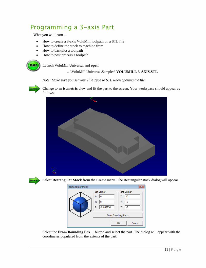
Change to an isometric view and fit the part to the screen. Your workspace should appear as
follows:
Select Rectangular Stock from the Create menu. The Rectangular stock dialog will appear.
Select the From Bounding Box… button and select the part. The dialog will appear with the
coordinates populated from the extents of the part.

12 | P a g e
Select OK and the stock will appear.
Select VoluMill 3-Axis from the Toolpaths menu. The Select Bodies dialog will appear.
Select the Select… button next to Part Bodies and then select the part.
Select the green check icon or press enter to accept.

13 | P a g e
Select the Select… button next to Stock Bodies
Select the stock
Select the green check icon or press enter to accept. Select the OK button.
The 3-Axis dialog will appear. The Tool/Speeds/Feeds tab lists all the parameters to define
the tool, the spindle speeds, and the feed rates. The second tab lists the parameters associated
with cutting.
Unlike traditional roughing, VoluMill is designed to run at much higher spindle speeds and
feed rates. The spindle speeds and feed rates we will use are only an example of what is
possible for machining a part like this in 1045 steel.
Enter 0.5 for the Tool Diameter
Enter 0.030for the Tool Corner Radius
Enter 1100 for the Spindle speed Enter 300.0 for the Feed rate
Enter 225.0 for the Plunge rate
Enter 1000.0 for the High Feed Rate
Set all other parameters as follows
.

14 | P a g e
Select the Cut Control tab.
Enter 0.5 for the Depth of Cut
Check the Final Step Height option and enter 0.1
Enter 0.15 for the Cut Width
Enter 0.01 for the Stock to Leave
Check the Side-Mill Only option
Set all other parameters as shown below.

15 | P a g e
Press OK and the system will generate a VoluMill toolpath.
Highlight the toolpath by moving the mouse over it, right-click, and then select Backplot
Toolpath.
Push the Play button to begin simulating the toolpath. Use the play speed to control how fast
the tool moves. Try changing views to look at the toolpath from different angles.

16 | P a g e
Highlight the toolpath by moving the mouse over it, right-click, and then select Post
Process.
The Post Process Operation dialog will open. Push the Browse… button to navigate to a
desired directory and provide an Output Filename.
Push the Post Process Now… button and the system will generate G-code for the VoluMill
toolpath.

17 | P a g e
Chapter 3
USER INTERFACE VoluMill Universal uses an industry-standard style interface with common controls to make it easy
to use.
Menus
File
New This choice will close the current file and begin a new session. If the current file has any changes
since it was last saved, a dialog will appear that provides an option to save the file.
Open This will display the File Open dialog to load a file. If the current file has any changes since it
was last saved, a dialog will appear that provides an option to save the file.
VoluMill Universal supports DXF and STL files. DXF files are required for 2-Axis operations
while STL files are required for 3-Axis operations.
When saving a file, a “.vmuc” extension is used.
Menus Toolbars
Workspace Status Bar Toolpath Manager Pane

18 | P a g e
Merge
Merge functions the same way Open does except that the current file is kept and the two
combined into a single file.
Save
This will save the current changes made to the file. If the file has not yet been saved a dialog will
appear to define the location and name of the file.
Save As
This will display a dialog to save the file to a different name.
Edit
Undo This choice reverses the last action.
Redo This choice reverses the last Undo action.
View
Fit
This choice adjusts the display scale so the geometry fits within the workspace.
Zoom Rectangle
This choice is used to zoom into a specific area within the workspace.
Pan
This choice is used to move the part within the workspace. Using this choice switches into a
panning mode. To exit from this mode press the Esc key.
Rotate
This choice is used to dynamically rotate the part within the workspace. Using this choice
switches into a rotation mode. To exit from this mode press the Esc key.
Top View through Isometric View
These choices display the part in its respective view.
Wireframe
This choice changes the STL model, Stock, and Backplotting tool to a wireframe or polygon
display mode.
Shaded
This choice changes the STL model, Stock, and Backplotting tool to a rendered display mode.
Active CS
This choice toggles the display of the current coordinate system’s axes.
Create
Rectangular Stock
This choice creates a rectangular stock model that is used when machining STL files only.
Coordinates for the opposing corners may be entered or the Bounding box button may be used to
automatically calculate the stock to contain the chosen STL model.

19 | P a g e
Cylindrical Stock
This choice creates a cylindrical stock model that is used when machining STL files only.
Values for the cylinder’s center, length, diameter, and corners may be entered as well as the axis
of orientation. The Bounding cylinder button may be used to automatically calculate the stock to
contain the chosen STL model.
Toolbars
Main
New This choice will close the current file and begin a new session. If the current file has any changes
since it was last saved, a dialog will appear that provides an option to save the file.
Open This will display the File Open dialog to load a file. If the current file has any changes since it
was last saved, a dialog will appear that provides an option to save the file.
VoluMill Universal supports DXF and STL files. DXF files are required for 2-Axis operations
while STL files are required for 3-Axis operations.
When saving a file, a “.vmuc” extension is used.
Save
This will save the current changes made to the file. If the file has not yet been saved a dialog will
appear to define the location and name of the file.
Undo This choice reverses the last action.
Redo This choice reverses the last Undo action.
About
Displays the version and build number.
View
Fit
This choice adjusts the display scale so the geometry fits within the workspace.
Zoom Rectangle
This choice is used to zoom into a specific area within the workspace.
Pan
This choice is used to move the part within the workspace. Using this choice switches into a
panning mode. To exit from this mode press the Esc key.
Rotate
This choice is used to dynamically rotate the part within the workspace. Using this choice
switches into a rotation mode. To exit from this mode press the Esc key.
Top View through Isometric View
These choices display the part in its respective view.

20 | P a g e
Shaded
This choice changes the STL model, Stock, and Backplotting tool to a rendered display mode.
Wireframe
This choice changes the STL model, Stock, and Backplotting tool to a wireframe or polygon
display mode.
Current Coordinate System
This lists the currently available coordinate systems and provides a choice to create new ones.
Whichever coordinate system is chosen will be used when creating new toolpaths.
The creation of coordinate systems is explained in detail later in this guide.
Toolpath
These choices are used to create VoluMill toolpaths for 2-axis, 2-axis Restmilling, 3-axis, and 3-
axis Restmilling respectfully.
Tools
These choices are used to backplot and post process toolpaths
Backplot
To animate the tool motion, highlight the desired toolpath, right-click and choose backplot.
Post Process
This icon will post process the currently checked toolpaths.
Push the Post Process Now… button and the system will generate G-code for the VoluMill
toolpath.
Toolpath position slider Play speed Show/Hide Tool
Cycle times Toolpath record type/coordinates Stop/Rewind, Step back,
Play/Pause, Step Forward

21 | P a g e
Select
This toolbar appears when applying VoluMill 3-Axis toolpaths. When a 3-Axis toolpath type is
selected, the following dialog will appear.
VoluMill Universal creates a solid body, or “mesh”, from any solid or surface model that has
been imported. These bodies can define the Part to machine, the Stock to machine from, or the
Check bodies to avoid.
Part Bodies When the Select… button is selected, the chosen body defines the surfaces to machine.
Stock Bodies When the Select… button is selected, the chosen body defines the surfaces to machine away to
the Part body(s).
Check Bodies When the Select… button is selected, the chosen body defines the surfaces to avoid.
When selecting any bodies, use the green check icon or hit enter to accept the current selections:
When selecting any bodies, use the red cancel icon or hit Esc to reject the current selections:
Selection Cursor When selecting bodies, there may be multiple possibilities depending on where the cursor is
placed. When that happens, the cursor will change to a tab-select cursor:
To toggle through the possibility selections, press the tab key.

22 | P a g e
Coordinate Systems Coordinate systems define the X, Y, Z axes used when creating toolpaths. There are two different
types of coordinate systems in VoluMill Universal, the World CS(coordinate system) or Current
CS.
The World CS is the default coordinate system that all others are relative to. It is represented by
the smaller X, Y, Z axes in the lower left corner of the workspace.
The Current CS is the coordinate system that is used when creating toolpaths. It is represented by
the larger X, Y, Z axes in the center of the workspace.
To define a new CS, select New Coordinate System… from the Coordinate System list:
Current Coordinate System Axes
World Coordinate System Axes

23 | P a g e
The Coordinate Systems dialog will appear:
Name
This is the name of the new coordinate system.
Origin
This is the X, Y, Z origin of the new coordinate system. When post processing, all X, Y, Z
values will be relative to this new origin. The values may be entered in the fields for each axis or the may be used to select a position on the part itself.
Axes
When creating a new CS there are options to align a specific axis parallel to a line, through a
point, and normal to a circle. There is also an option to invert an axis.
Parallel – This aligns the axis to be parallel to a selected line
Though Point – This aligns the axis to intersect a selected point
Invert – This inverts, or flips, the axis
Normal to Circle – This makes the Z axis normal to a circle
XY Plane Rotation
This is the X, Y, Z origin of the new coordinate system. When post processing, all X, Y, Z
values will be relative to this new origin.
To edit or delete an existing coordinate system, select Edit Active CS… or Delete Active CS…. It’s
important to note that you must set the active CS before editing or deleting it.
Any toolpaths the use an edited or delete CS will be represented by a and will require
regeneration with a new CS.

24 | P a g e
active setup inactive setup
Toolpath Manager The Toolpath Manager is used to organize and manage toolpaths within individual setups.
Toolpaths may be managed in different ways to suit your process or method. However, the
intended design is to have setups reflect different setups you would use when machining your
part. It is common to have a separate setup to machine each side of a part, pause to change
clamps, etc. When using setups a separate coordinate system and origin may be required as well.
When VoluMill Universal first opens there is a single active setup:
Setups are either active or inactive:
To create a setup, right-click on Operations and select Create New Setup:

25 | P a g e
As new toolpaths are created they are added to the active Setup:
There are eight buttons at the top of the Toolpath Mgr. which buttons are available depend on
what is checked.
Edit…
This button opens the dialog for the tool and machining parameters for the checked toolpath so
they may be changed. This is only available when a single toolpath is checked.
When a toolpath is edited it is represented by a
Regen
This button regenerates the checked toolpaths. This must be done to edited toolpaths to save the
changes. There is no limit to the number of toolpaths that may be regenerated.
Post
This button post processes the checked toolpaths. There is no limit to the number of toolpaths
that may be post processed at once.
Delete
This button post deletes the checked toolpaths. There is no limit to the number of toolpaths that
may be post delete at once.

26 | P a g e
Hide/Unhide
These buttons hide or display the checked toolpath deletes the checked toolpaths. There is no
limit to the number of toolpaths that may be hidden/shown at once.
Naming
To rename a setup or toolpath click once, then click again. The Operations cannot be renamed.
Minimizing/Maximizing
To expand or minimize setups click on the +/- or double-click on the individual step or
Operations.
Also, the width to the Toolpath Manager pane may be resized by hovering over the right edge of
the pane until the cursor changes and then holding down the left mouse button and dragging.

27 | P a g e
Workspace
Right-click
The right-click lists choices that are only available to the highlighted elements or toolpath.
Delete
Deletes the highlighted toolpath and/or geometry.
Change Color
Displays a dialog to select a new color for the highlighted geometry.
Edit Operation
This choice opens the dialog for the tool and machining parameters for the highlighted toolpath
so they may be changed.
Regenerate Operation
This choice reprocesses the highlighted toolpath.
Post Operation
This choice displays the post-processing dialog for the highlighted toolpath.
Backplot Operation
This choice displays the backplot dialog for the highlighted toolpath.
Chaining When creating a VoluMill 2-Axis toolpath, a dialog will appear offering different options
Planar
This option allows chaining in any direction
3D
This option constrains the chaining within a plane
right-click on toolpath & geometry right-click on geometry right-click on toolpath

28 | P a g e
Part/Material
These options define the type of the next element in the chain.
Reverse Direction
The first element of a chain will display an arrow indicating the direction of the chain. Push this
button to reverse the direction.
The direction of the chain has no effect on the toolpath.
Back Up 1 Step
Pushing this button will step backwards along the chain one element at a time.
Finished Chaining
After all the profiles have been chained, push this button to proceed.
Units When installing VoluMill Universal the desired units are defined as either inch or Metric(mm):
To change the current units select the Inch or MM in the right corner of the status bar:
Changing the units defines the default startup state when VoluMill Universal is opened the next
time.
29 | P a g e
Chapter 4
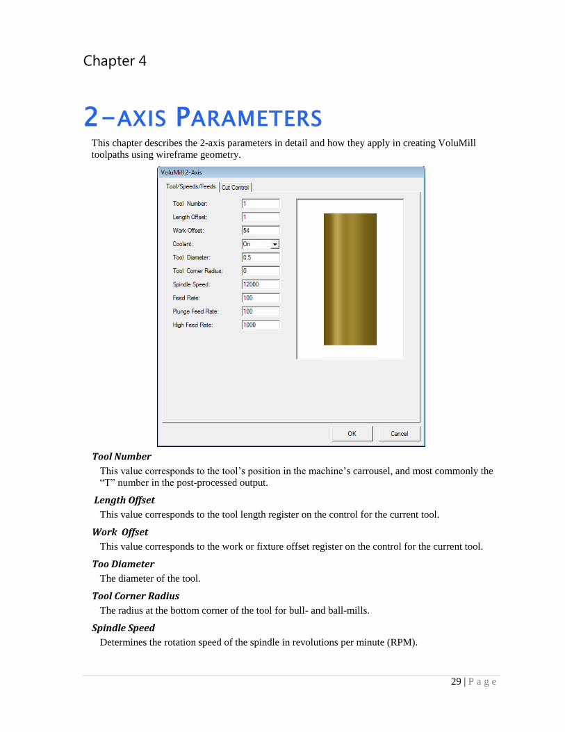
2-AXIS PARAMETERS This chapter describes the 2-axis parameters in detail and how they apply in creating VoluMill
toolpaths using wireframe geometry.
Tool Number
This value corresponds to the tool’s position in the machine’s carrousel, and most commonly the
“T” number in the post-processed output.
Length Offset
This value corresponds to the tool length register on the control for the current tool.
Work Offset
This value corresponds to the work or fixture offset register on the control for the current tool.
Too Diameter
The diameter of the tool.
Tool Corner Radius
The radius at the bottom corner of the tool for bull- and ball-mills.
Spindle Speed
Determines the rotation speed of the spindle in revolutions per minute (RPM).
30 | P a g e
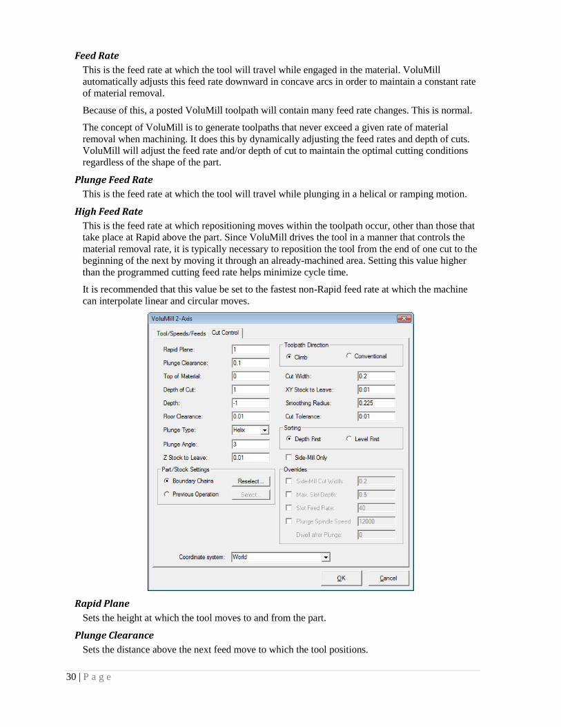
Feed Rate
This is the feed rate at which the tool will travel while engaged in the material. VoluMill
automatically adjusts this feed rate downward in concave arcs in order to maintain a constant rate
of material removal.
Because of this, a posted VoluMill toolpath will contain many feed rate changes. This is normal.
The concept of VoluMill is to generate toolpaths that never exceed a given rate of material
removal when machining. It does this by dynamically adjusting the feed rates and depth of cuts.
VoluMill will adjust the feed rate and/or depth of cut to maintain the optimal cutting conditions
regardless of the shape of the part.
Plunge Feed Rate
This is the feed rate at which the tool will travel while plunging in a helical or ramping motion.
High Feed Rate
This is the feed rate at which repositioning moves within the toolpath occur, other than those that
take place at Rapid above the part. Since VoluMill drives the tool in a manner that controls the
material removal rate, it is typically necessary to reposition the tool from the end of one cut to the
beginning of the next by moving it through an already-machined area. Setting this value higher
than the programmed cutting feed rate helps minimize cycle time.
It is recommended that this value be set to the fastest non-Rapid feed rate at which the machine
can interpolate linear and circular moves.
Rapid Plane
Sets the height at which the tool moves to and from the part.
Plunge Clearance
Sets the distance above the next feed move to which the tool positions.

31 | P a g e
Top of Material
Sets the height of the material in the Z axis.
Depth of Cut
Defines the maximum depth of cut. If the value does not divide equally into the total depth then
VoluMill subdivides the number of cuts to create equal depths of cut.
Depth
Sets the overall depth of the area to be machined.
Floor Clearance
The value entered here establishes the Z-component of a helical move that is used when entering
or exiting a cut. Only non-negative values are allowed. If a positive value is entered, repositioning
moves between cuts will take place above the already-machined floor. If zero is entered, the tool
will drag across the already-machined floor during these moves. In this case, set the High Feed
Rate parameter to be no greater than the cutting feed rate to help ensure more consistent tool
marks on the floor.
Plunge Type
This parameter defines the type of entry motion VoluMill uses to machine to the desired depth of
cut.
Helix
This Plunge type uses a helix to machine to the desired depth of cut. This is the default Plunge
type and is recommended for harder materials.

32 | P a g e
Ramp
This Plunge type uses a special ramping motion to machine to the desired depth of cut. VoluMill
calculates the optimal position and shape of the ramp to create a transition area. This transition
area is then used to connect from the end of one cut to the next while disengaged from the
material at the High Feed Rate. This Plunge type is recommended for softer materials.
Plunge Angle
This parameter establishes the rate of descent, in degrees, at which the tool enters the material
from the top, as is required when machining completely enclosed areas (pockets). VoluMill uses
the entered value as a not-to-exceed value, meaning that the actual ramp angle may be adjusted
downward from the entered value as needed to fill the ramping area. VoluMill automatically
calculates the location, length, and orientation of the ramp based on the shape of the selected
geometry. The feed rate for the plunge motion is determined by the Plunge Rate parameter.
Z Stock to Leave
The amount of material that will remain on the floor after the machining is complete.
Boundary Chains
When editing an existing toolpath this option prides the ability to add new chains or delete
existing ones.
Previous Operation
When editing an existing toolpath this option prides the ability to define a different toolpath
operation to use as a reference when rest-milling.
Toolpath Direction
Climb milling cuts the chained geometry with the tool rotating opposite the direction of travel
along the cutting side of the tool. This type of machining generally produces a smoother surface
finish than conventional milling.
Conventional milling cuts the chained geometry with the tool rotating in the same direction as the
direction of travel along the cutting side of the tool.

33 | P a g e
Cut Width
Commonly known as the stepover. With VoluMill, it’s important to note that any Cut Width
value that is less than the diameter of the flat portion of the tool can be used without fear of
leaving uncut stands of material behind. For example, you can use up to a 100% Cut Width with a
flat end mill.
XY Stock to Leave
The amount of material that will remain on the walls after the machining is complete.
Smoothing Radius
This is the minimum radius the tool will transverse when cutting. To machine into sharp corners
or tight areas, VoluMill has to make small moves that may be more effectively accomplished
using a smaller tool in a clean-up operation. The optimal, and default, Smoothing Radius is 45%
of the tool diameter. At this value VoluMill can reach velocities that can dramatically reduce
cycle times. However, it may leave areas uncut.
Using a smaller value may enable the tool to machine more material. This, however, may be less
efficient than switching to a smaller tool and using another VoluMill toolpath to machine the
remaining material.

34 | P a g e
The smallest value allowed is 5% of the tool diameter. VoluMill is designed to never make sharp
directional changes while in the cut. This means that if your part has a fillet in the corner that is
equal to the tool radius, a small amount of material will be left in the corners, even if the
Smoothing radius value is set to the minimum allowed.
VoluMill is a roughing technology and it is assumed that a finish pass will follow.
Cut Tolerance
This value defines the tolerance used when machining profiles that include splines or polylines.
Depth First
Each pocket will be machined to the total depth before the next one.
Level First
Each pocket will be machined to the Depth of Cut before the next one. This is helpful when
machining pockets that have thin walls.
Side-Mill Only
VoluMill achieves its superior cutting performance by striving to maintain a constant rate of
material removal throughout the toolpath, regardless of the shape of the geometry.
Two strategies are considered when milling in confined areas: Side Milling and Slot Milling. If
this checkbox is unchecked, VoluMill will automatically choose the strategy that produces the
fastest cycle time using the current feed rate and distance traveled. Depending on the shape of the
part, both methods may be used.
35 | P a g e
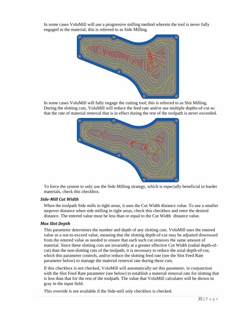
In some cases VoluMill will use a progressive milling method wherein the tool is never fully
engaged in the material; this is referred to as Side Milling.
In some cases VoluMill will fully engage the cutting tool; this is referred to as Slot Milling.
During the slotting cuts, VoluMill will reduce the feed rate and/or use multiple depths-of-cut so
that the rate of material removal that is in effect during the rest of the toolpath is never exceeded.
To force the system to only use the Side Milling strategy, which is especially beneficial in harder
materials, check this checkbox.
Side-Mill Cut Width
When the toolpath Side mills in tight areas, it uses the Cut Width distance value. To use a smaller
stepover distance when side milling in tight areas, check this checkbox and enter the desired
distance. The entered value must be less than or equal to the Cut Width distance value.
Max Slot Depth
This parameter determines the number and depth of any slotting cuts. VoluMill uses the entered
value as a not-to-exceed value, meaning that the slotting depth-of-cut may be adjusted downward
from the entered value as needed to ensure that each such cut removes the same amount of
material. Since these slotting cuts are invariably at a greater effective Cut Width (radial depth-of-
cut) than the non-slotting cuts of the toolpath, it is necessary to reduce the axial depth-of-cut,
which this parameter controls, and/or reduce the slotting feed rate (see the Slot Feed Rate
parameter below) to manage the material removal rate during these cuts.
If this checkbox is not checked, VoluMill will automatically set this parameter, in conjunction
with the Slot Feed Rate parameter (see below) to establish a material removal rate for slotting that
is less than that for the rest of the toolpath. The value that VoluMill calculates will be shown in
gray in the input field.
This override is not available if the Side-mill only checkbox is checked.

36 | P a g e
Slot Feed Rate
This is the feed rate used for the slotting cuts. Since these slotting cuts are invariably at a greater
effective Cut Width (radial depth-of-cut) than the non-slotting cuts of the toolpath, it is necessary
to reduce the slotting feed rate, which this parameter controls, and/or reduce the axial depth-of-
cut (see the Max.slot depth parameter above) to manage the material removal rate during these
cuts.
If this checkbox is not checked, VoluMill will automatically set this parameter, in conjunction
with the Max. slot depth parameter (see above) to establish a material removal rate for slotting
that is less than that for the rest of the toolpath. The value that VoluMill calculates will be shown
in gray in the input field.
This override is not available if the Side-mill only checkbox is checked.
Plunge Spindle Speed
This is the spindle speed used for the Plunge motion.
If this checkbox is not checked, VoluMill will use the Spindle speed defined on the toolpath
parameters tab. In softer materials this may be acceptable. However, for harder materials it is
recommended that the Plunge spindle speed be reduced to sync with the Plunge rate.
Dwell after Plunge
This is a value used to force a dwell after the tool has completed the plunge motion. Some
machines will not pause to begin feeding until the programmed spindle speed is reached. For
these machines the dwell will give the machine time to do so.
Coordinate System:
This lists the currently available coordinate systems. When creating a toolpath, VoluMill uses the
current CS, or coordinate system defined at the top of the screen in the view toolbar. This list
provides an opportunity to use a different CS if desired.

37 | P a g e
Chapter 5
3-AXIS PARAMETERS This chapter describes the 3-Axis parameters in detail and how they apply in creating VoluMill
toolpaths using STL geometry.
Tool Number
This value corresponds to the tool’s position in the machine’s carrousel, and most commonly the
“T” number in the post-processed output.
Length Offset
This value corresponds to the tool length register on the control for the current tool.
Work Offset
This value corresponds to the work or fixture offset register on the control for the current tool.
Too Diameter
The diameter of the tool.
Tool Corner Radius
The radius at the bottom corner of the tool for bull- and ball-mills.
Spindle Speed
Determines the rotation speed of the spindle in revolutions per minute (RPM).
38 | P a g e
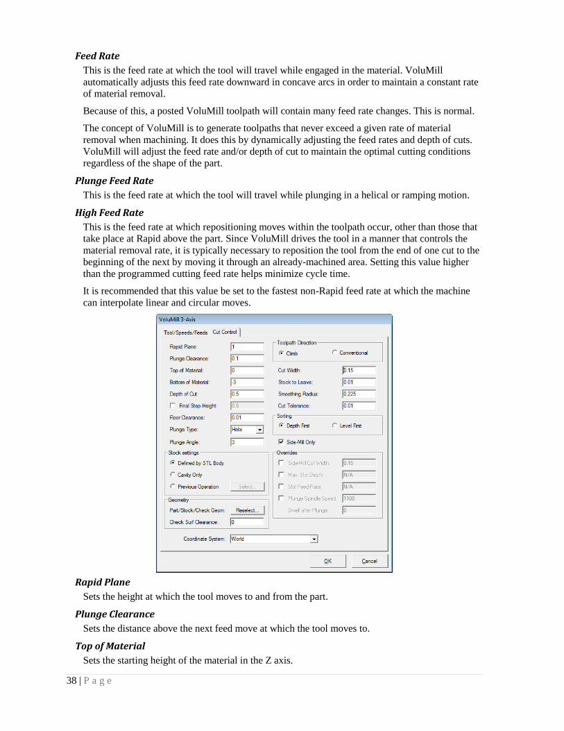
Feed Rate
This is the feed rate at which the tool will travel while engaged in the material. VoluMill
automatically adjusts this feed rate downward in concave arcs in order to maintain a constant rate
of material removal.
Because of this, a posted VoluMill toolpath will contain many feed rate changes. This is normal.
The concept of VoluMill is to generate toolpaths that never exceed a given rate of material
removal when machining. It does this by dynamically adjusting the feed rates and depth of cuts.
VoluMill will adjust the feed rate and/or depth of cut to maintain the optimal cutting conditions
regardless of the shape of the part.
Plunge Feed Rate
This is the feed rate at which the tool will travel while plunging in a helical or ramping motion.
High Feed Rate
This is the feed rate at which repositioning moves within the toolpath occur, other than those that
take place at Rapid above the part. Since VoluMill drives the tool in a manner that controls the
material removal rate, it is typically necessary to reposition the tool from the end of one cut to the
beginning of the next by moving it through an already-machined area. Setting this value higher
than the programmed cutting feed rate helps minimize cycle time.
It is recommended that this value be set to the fastest non-Rapid feed rate at which the machine
can interpolate linear and circular moves.
Rapid Plane
Sets the height at which the tool moves to and from the part.
Plunge Clearance
Sets the distance above the next feed move at which the tool moves to.
Top of Material
Sets the starting height of the material in the Z axis.

39 | P a g e
Bottom of Material
Sets the depth of the toolpath in the Z axis.
Depth of Cut
Defines the maximum depth of cut. If the value does not divide equally into the total depth,
VoluMill subdivides the number of cuts to create equal depths of cut.
Final step height
Use this option to control the height of the steps that will remain. Instead of making a shallow
depth of cut across the entire part to leave smaller steps, VoluMill can efficiently first machine
larger steps and then automatically remachine to leave smaller steps. By doing this, the tool can
remove the bulk of material most efficiently and still leave smaller steps for a semi-finish or
finish toolpath.
The tool begins by machining the part using the Depth of Cut value. After the entire part is
machine at each Depth of Cut, the tool then reduces the step using the Final Step Height value.

40 | P a g e
Floor Clearance
The value entered here establishes the Z-component of a helical move that is used when entering
or exiting a cut. Only non-negative values are allowed. If a positive value is entered, repositioning
moves between cuts will take place above the already-machined floor. If zero is entered, the tool
will drag across the already-machined floor during these moves. In this case, set the High Feed
Rate parameter to be no greater than the cutting feed rate to help ensure more consistent tool
marks on the floor.
Plunge Type
This parameter defines the type of entry motion VoluMill uses to machine to the desired depth of
cut.
Helix
This Plunge type uses a helix to machine to the desired depth of cut. This is the default Plunge
type and is recommended for harder materials.
Ramp
This Plunge type uses a special ramping motion to machine to the desired depth of cut. VoluMill
calculates the optimal position and shape of the ramp to create a transition area. This transition
area is then used to connect from the end of one cut to the next while disengaged from the
material at the High feed rate. This Plunge type is recommended for softer materials.

41 | P a g e
Plunge Angle
This parameter establishes the rate of descent, in degrees, at which the tool enters the material
from the top, as is required when machining completely enclosed areas (pockets). VoluMill uses
the entered value as a not-to-exceed value, meaning that the actual ramp angle may be adjusted
downward from the entered value as needed to fill the ramping area. VoluMill automatically
calculates the location, length, and orientation of the ramp based on the shape of the selected
geometry. The feed rate for the plunge motion is determined by the Plunge rate parameter.
Defined by STL Body
VoluMill can use an STL body as the stock to machine from. Use the Merge choice under the
Files menu to add the STL file.
Cavity only
This option should be used when machining a cavity from material having a flat top surface. The
benefit of using this option is that stock need not be defined separately.
If the Cavity machining only option is used on a core or a shape that doesn’t have a flat top
surface, the toolpath will begin machining at a level where it can create a closed area. This can
create a situation where the first depth of cut is too deep. Make sure to use a stock definition
appropriate for the part shape to avoid this.

42 | P a g e
Previous Operation
This option uses a chosen operation to determine the remaining material to machine.
Part/Stock/Check Geom
When editing an existing toolpath this option provides the ability to select a different part, stock,
or check bodies to machine.
Check Surf Clearance
This is the distance the tool will stay away from any surfaces or solids selected as check surfaces.
Toolpath Direction
Climb milling cuts the chained geometry with the tool rotating opposite the direction of travel
along the cutting side of the tool. This type of machining generally produces a smoother surface
finish than conventional milling.
Conventional milling cuts the chained geometry with the tool rotating in the same direction as the
direction of travel along the cutting side of the tool.
Cut Width
Commonly known as the stepover. With VoluMill it’s important to note that any Cut Width value
that is less than the diameter of the flat portion of the tool can be used without fear of leaving
uncut stands of material behind. For example, you can use up to a 100% Cut Width with a flat
end mill.
Stock to leave
The amount of material that will remain on the part after the machining is complete.
Smoothing Radius
This is the minimum radius the tool will transverse when cutting. To machine into sharp corners
or tight areas, VoluMill has to make small moves that may be more effectively accomplished
using a smaller tool in a clean-up operation. The optimal, and default, Smoothing radius is 45%
of the tool diameter. At this value VoluMill can reach velocities that can dramatically reduce
cycle times. However, it may leave areas uncut.
43 | P a g e
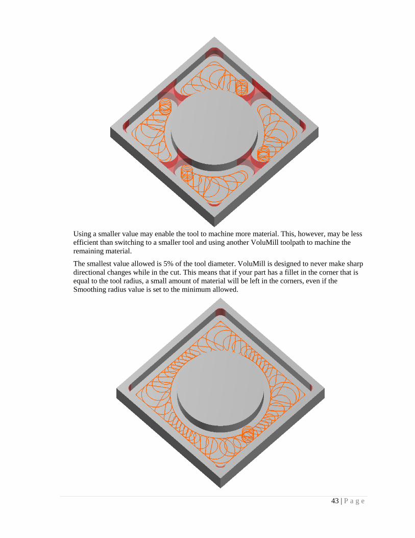
Using a smaller value may enable the tool to machine more material. This, however, may be less
efficient than switching to a smaller tool and using another VoluMill toolpath to machine the
remaining material.
The smallest value allowed is 5% of the tool diameter. VoluMill is designed to never make sharp
directional changes while in the cut. This means that if your part has a fillet in the corner that is
equal to the tool radius, a small amount of material will be left in the corners, even if the
Smoothing radius value is set to the minimum allowed.

44 | P a g e
VoluMill is a roughing technology and it is assumed that a finish pass will follow.
Cut Tolerance
This value defines the tolerance used when machining surfaces.
Depth First
Each pocket will be machined to the total depth before the next one.
Level First
Each pocket will be machined to the Depth of Cut before the next one. This is helpful when
machining pockets that have thin walls.
Side-Mill Only
VoluMill achieves its superior cutting performance by striving to maintain a constant rate of
material removal throughout the toolpath, regardless of the shape of the geometry.
Two strategies are considered when milling in confined areas: Side Milling and Slot Milling. If
this checkbox is unchecked, VoluMill will automatically choose the strategy that produces the
fastest cycle time using the current feed rate and distance traveled. Depending on the shape of the
part, both methods may be used.
In some cases VoluMill will use a progressive milling method wherein the tool is never fully
engaged in the material; this is referred to as Side Milling.
In some cases VoluMill will fully engage the cutting tool; this is referred to as Slot Milling.
During the slotting cuts, VoluMill will reduce the feed rate and/or use multiple depths-of-cut so
that the rate of material removal that is in effect during the rest of the toolpath is never exceeded.
To force the system to only use the Side Milling strategy, which is especially beneficial in harder
materials, check this checkbox.

45 | P a g e
Side-Mill Cut Width
When the toolpath Side mills in tight areas, it uses the Cut Width distance value. To use a smaller
Cut Width distance when side milling in tight areas, check this checkbox and enter the desired
distance. The entered value must be less than or equal to the Cut Width distance value.
Max Slot Depth
This parameter determines the number and depth of any slotting cuts. VoluMill uses the entered
value as a not-to-exceed value, meaning that the slotting depth-of-cut may be adjusted downward
from the entered value as needed to ensure that each such cut removes the same amount of
material. Since these slotting cuts are invariably at a greater effective Cut Width (radial depth-of-
cut) than the non-slotting cuts of the toolpath, it is necessary to reduce the axial depth-of-cut,
which this parameter controls, and/or reduce the slotting feed rate (see the Slot Feed Rate
parameter below) to manage the material removal rate during these cuts.
Slot Feed Rate
This is the feed rate used for the slotting cuts. Since these slotting cuts are invariably at a greater
effective Cut Width (radial depth-of-cut) than the non-slotting cuts of the toolpath, it is necessary
to reduce the slotting feed rate, which this parameter controls, and/or reduce the axial depth-of-
cut (see the Max.slot depth parameter above) to manage the material removal rate during these
cuts.
If this checkbox is not checked, VoluMill will automatically set this parameter, in conjunction
with the Max. slot depth parameter (see above) to establish a material removal rate for slotting
that is less than that for the rest of the toolpath. The value that VoluMill calculates will be shown
in gray in the input field.
This override is not available if the Side-mill only checkbox is checked.
Plunge Spindle Speed
This is the spindle speed used for the Plunge motion.
If this checkbox is not checked, VoluMill will use the Spindle speed defined on the toolpath
parameters tab. In softer materials this may be acceptable. However, for harder materials it is
recommended that the Plunge spindle speed be reduced to sync with the Plunge rate.
Dwell after Plunge
This is a value used to force a dwell after the tool has completed the plunge motion. Some
machines will not pause to begin feeding until the programmed spindle speed is reached. For
these machines the dwell will give the machine time to do so.
Coordinate System:
This lists the currently available coordinate systems. When creating a toolpath, VoluMill uses the
current CS, or coordinate system defined at the top of the screen in the view toolbar. This list
provides an opportunity to use a different CS if desired.

46 | P a g e
47 | P a g e
Chapter 6
POST PROCESSING VoluMill offers a post processor that is capable of formatting the output to wide range of formats.
The following does not explain every detail of what the capabilities are but should suffice for basic
editing.
For further help or assistance, contact your local VoluMill distributor or contact Celeritive
Technologies directly.
Post Processor Files
If the default installation path is accepted during installation the sample post processors will be
installed into:
C:\Program Files\Celeritive Technologies\VoluMill Universal\Post
If a different path and directory is defined during installation then they will be found in:
.\Post
To open a post processor navigate to the ..\Post directory and double-click on the desired post
processor. It will open in Notepad. Any editor may be used to edit a post processor.
VoluMill post processors use *.vmpst extensions. Although any extension may be used, *vmpst is
recommended.
Post Processor Formatting
VoluMill post processors are designed to make them easy to create and modify while providing
flexibility to support many different output formats.
Version
Each post should have the version defined on the first line. This comment should not be removed
from the post processor.
// VoluMill Post Processor v1.0.0 !!Do not delete this line!!
Comments
Comments may be added to describe certain characteristics of particular formats within the post.
They also help when editing a post after a period of time to describe specifics. Comments are
solely used for descriptive text within the post processor and have no effect on the output.
To create a comment begin the line with “//”. Example:
// This is a comment in a post processor
Comments must be on separate lines. Anything may follow the “//”.
Sections
Sections are used to perform specific tasks such as formatting the output of a tool change to
defining what letter addresses are modal, etc.

48 | P a g e
There are specific sections available. The following describes the available sections:
section modal
This section defines what letter addresses are modal, or not repeated if the value is the same.
section format
This section defines the decimal formatting for the letter addresses.
section startup
This section defines the format for the start of the program.
section rapid
This section defines the format for the rapid motion of the toolpath, typically G0 blocks.
section linear
This section defines the format for the linear feed motion of the toolpath, typically G1 blocks.
section cw
This section defines the format for the clockwise circular motion of the toolpath, typically G2
blocks.
section ccw
This section defines the format for the counter clockwise circular motion of the toolpath,
typically G3 blocks.
section spindlespeed
This section defines the format for the spindle speed changes.
section shutdown
This section defines the format for the end of the program.
Formatting within a section begins with “{“ and ends with “}”
Letter Addresses
Letter addressed are not limited to a single character. Almost any combination of characters may
be used except “ [ { } ] ” . Letter addresses must be followed by variables. Otherwise the post
processor treats the characters at straight text.
Variables
Variables are not case sensitive. The following variables are provided:
toolnumber The current tool number.
tooldiameter The current tool diameter.
toolcornerradius The current tool corner radius.
topmaterialz
The absolute z coordinate of the top of the stock.
rapidplanez
The absolute z coordinate of the rapid plane.
startx
The first absolute x coordinate of the toolpath.
starty

49 | P a g e
The first absolute y coordinate of the toolpath.
startz
The first absolute z coordinate of the toolpath.
endx
The last absolute x coordinate of the toolpath.
endy
The last absolute y coordinate of the toolpath.
endz
The last absolute z coordinate of the toolpath.
ncfilename
The filename.
sequencenumber
The calculated sequence number.
sequenceincrement
The sequence number increment.
angle
The swept angle of the arc.
x
The current absolute x coordinate.
y
The current absolute y coordinate.
z
The current absolute z coordinate.
i
The current signed distance along the x axis from the end of an arc to its center.
j
The current signed distance along the y axis from the end of an arc to its center.
r
The current radius of an arc.
f
The current feed rate.
s
The current spindle speed.
prevx
The previous x coordinate.
prevy
The previous y coordinate.
prevz
The previous z coordinate.
centerx
The current absolute x axis coordinate of the center of an arc.
centery
The current absolute y axis coordinate of the center of an arc.

50 | P a g e
dirx
The x component of the tangent vector at the start of an arc.
diry
The y component of the tangent vector at the start of an arc.
linearizeHelix = 0.001
Breaks helixes into point-to-point moves. The chord is defined by the value.
linearizeArc = 0.001
Breaks arcs into point-to-point moves. The chord is defined by the value.
lengthOffset
The current tool length offset.
workOffset
The current tool length offset.
dwell
The current dwell value.
tolerance
The programmed tolerance.
opName
The name of the operation as listed in the Operation Manager.
toolDescription
The description of the tool. There are three descriptions:
END_MILL_<tool diameter>
BULL_MILL_<tool diameter>
BALL_MILL_<tool diameter>
Letter Address Formatting
Decimal formatting is accomplished as follows:
“variable” “number of digits left of decimal” “decimal character” “number of digits left of decimal”
The number of digits may be a range or forced. The following are example formats:
Format Input value Output
F 0-4 “.” 0-3 1.25 F1.25
F 4 “.”3 1.25 F0001.250
F 4 “” 3 1.25 F0001250
F 0-4 “.” 3 1.25 F1.250
F 0-4 “.” 1-3 1 F1.0
F 1-4 “.” 1-3 0 0.0

51 | P a g e
Chapter 7
TROUBLESHOOTING The following identifies solutions to problems you may encounter and attempts to answer
frequently asked questions.
If your issue isn’t addressed here, please refer to the Getting Help section in chapter 1, or contact
Once the VoluMill progress dialog is shown, it may take a few seconds to create the toolpath.
Complex shapes may take a little longer. It is possible that the specified tool cannot fit into the
selected geometry within VoluMill’s motion requirements, which results in no toolpath being
generated.
Corners not completely machined? To avoid sharp directional changes and maintain smooth
motion, VoluMill, by default, will not generate the sharp moves required to machine corners
that are less than or equal to the tool radius. Reduce the Smoothing radius to make the tool
machine farther into corners.
Narrow areas uncut? To avoid sharp directional changes and maintain smooth motion,
VoluMill uses a dynamically calculated minimum radius in the toolpath. This can result in
material not being machined in areas where the tool can fit. Reduce the Smoothing radius to
make the tool machine further into narrow areas. Please note, however, that if a smaller tool
will subsequently be used, it may be more efficient to leave the Smoothing radius at a higher
value and let the smaller tool remove the uncut material.

© Celeritive Technologies, Inc. 2010 All Rights Reserved VoluMill Universal Reference Guide v2.1


![Reference Guide Oracle FLEXCUBE Universal Banking · Reference Guide . Oracle FLEXCUBE Universal Banking . Release 12.0 [May] [2012] Oracle Part Number E51527-01](https://static.documents.pub/doc/80x56/5ac8c8d87f8b9aa3298c68ed/reference-guide-oracle-flexcube-universal-banking-guide-oracle-flexcube-universal.jpg)


