42
Volvo Vehicle Communications Software Manual August 2013 EAZ0025B47A Rev. C
| Date post: | 31-Dec-2016 |
| Category: |
Documents |
| Upload: | nguyenthuy |
| View: | 226 times |
| Download: | 1 times |

VolvoVehicle Communications
Software Manual
August 2013
EAZ0025B47A Rev. C

Trademarks
Snap-on is a trademark of Snap-on Incorporated.
All other marks are trademarks or registered trademarks of their respective holders.
Copyright Information
©2013 Snap-on Incorporated. All rights reserved.
Disclaimer of Warranties and Limitation of Liabilities
The information, specifications and illustrations in this manual are based on the latest information available at the time of printing. While the authors have taken due care in the preparation of this manual, nothing contained herein:
• Modifies or alters in any way the standard terms and conditions of the purchase, lease, or rental agreement under the terms of which the equipment to which this manual relates was acquired.
• Increases in any way the liability to the customer or to third parties.
Snap-on reserves the right to make changes at any time without notice.
IMPORTANT:Before operating or maintaining this unit, please read this manual carefully paying extra attention to the safety warnings and precautions.
Visit our website at:http://diagnostics.snapon.com (North America)
http://www1.snapon.com/diagnostics/uk (United Kingdom)
http://snapontools.com.au (Australia and New Zealand)
For Technical Assistance
Call:
1-800-424-7226 (North America)
+44 (0) 845 601 4736 (United Kingdom)
1800-810-581(Australia and New Zealand)
E-mail:
[email protected] (North America)
[email protected] (United Kingdom)
[email protected] (Australia and New Zealand)
For technical assistance in all other markets, contact your selling agent.
ii
Safety Information
For your own safety and the safety of others, and to prevent damage to the equipment and vehicles upon which it is used, it is important that the accompanying Important Safety Instructions be read and understood by all persons operating, or coming into contact with, the equipment. We suggest you store a copy near the unit in sight of the operator.
This product is intended for use by properly trained and skilled professional automotive technicians. The safety messages presented throughout this manual are reminders to the operator to exercise extreme care when using this test instrument.
There are many variations in procedures, techniques, tools, and parts for servicing vehicles, as well as in the skill of the individual doing the work. Because of the vast number of test applications and variations in the products that can be tested with this instrument, we cannot possibly anticipate or provide advice or safety messages to cover every situation. It is the automotive technician’s responsibility to be knowledgeable of the system being tested. It is essential to use proper service methods and test procedures. It is important to perform tests in an appropriate and acceptable manner that does not endanger your safety, the safety of others in the work area, the equipment being used, or the vehicle being tested.
It is assumed that the operator has a thorough understanding of vehicle systems before using this product. Understanding of these system principles and operating theories is necessary for competent, safe and accurate use of this instrument.
Before using the equipment, always refer to and follow the safety messages and applicable test procedures provided by the manufacturer of the vehicle or equipment being tested. Use the equipment only as described in this manual.
Read, understand and follow all safety messages and instructions in this manual, the accompanying safety manual, and on the test equipment.
Safety Message ConventionsSafety messages are provided to help prevent personal injury and equipment damage. All safety messages are introduced by a signal word indicating the hazard level.
� ������Indicates an imminently hazardous situation which, if not avoided, will result in death or serious injury to the operator or to bystanders.
� �������Indicates a potentially hazardous situation which, if not avoided, could result in death or serious injury to the operator or to bystanders.
� �����Indicates a potentially hazardous situation which, if not avoided, may result in moderate or minor injury to the operator or to bystanders.
i
Safety Information Important Safety Instructions
Safety messages contain three different type styles.
• Normal type states the hazard.
• Bold type states how to avoid the hazard.
• Italic type states the possible consequences of not avoiding the hazard.
An icon, when present, gives a graphical description of the potential hazard.
Example:
� �������Risk of unexpected vehicle movement.• Block drive wheels before performing a test with engine running.
A moving vehicle can cause injury.
Important Safety InstructionsFor a complete list of safety messages, refer to the accompanying safety manual.
SAVE THESE INSTRUCTIONS
ii

Contents
Safety Information ....................................................................................................................... i
Contents ...................................................................................................................................... 1
Chapter 1: Using This Manual ................................................................................................... 3
Conventions.................................................................................................................................. 3Bold Text ................................................................................................................................ 3Symbols ................................................................................................................................. 3Terminology ........................................................................................................................... 4Notes and Important Messages ............................................................................................. 4Procedures............................................................................................................................. 4
Chapter 2: Introduction.............................................................................................................. 5
Chapter 3: Operations................................................................................................................ 6
Identifying the Test Vehicle .......................................................................................................... 7Selecting a System for Testing..................................................................................................... 7System Main Menu Options ......................................................................................................... 7
Codes..................................................................................................................................... 8Clear Codes ........................................................................................................................... 8Data ....................................................................................................................................... 8Functional Tests..................................................................................................................... 8Review ECU ID ...................................................................................................................... 9
Connecting to a Test Vehicle...................................................................................................... 10
Chapter 4: Testing .................................................................................................................... 11
Engine Management .................................................................................................................. 11Codes................................................................................................................................... 11Clear Codes ......................................................................................................................... 11Data ..................................................................................................................................... 12Functional Tests................................................................................................................... 12
Transmission .............................................................................................................................. 12Codes................................................................................................................................... 12Clear Codes ......................................................................................................................... 12Data ..................................................................................................................................... 13Functional Tests................................................................................................................... 13
Antilock Brakes........................................................................................................................... 13Codes................................................................................................................................... 13Clear Codes ......................................................................................................................... 13Data ..................................................................................................................................... 14Functional Tests................................................................................................................... 14
Airbag ......................................................................................................................................... 14Codes................................................................................................................................... 14Clear Codes ......................................................................................................................... 14Data ..................................................................................................................................... 15
1

Contents
Electronic Throttle Module.......................................................................................................... 15Service Interval Reset ................................................................................................................ 15
Chapter 5: Data Parameters .................................................................................................... 16
Interpreting Pressure Parameters .............................................................................................. 17Alphabetic List of Parameters..................................................................................................... 18Parameter Definitions ................................................................................................................. 22
Appendix A: Troubleshooting ................................................................................................. 32
Communication Problems .......................................................................................................... 32Check scan tool operation ................................................................................................... 32Check the Malfunction Indicator Lamp................................................................................. 32Testing the Diagnostic Connector — 16-pin DLC ................................................................ 32
Appendix B: Terms and Acronyms......................................................................................... 35
Terms ......................................................................................................................................... 35Acronyms.................................................................................................................................... 35
Index .......................................................................................................................................... 38
2

Chapter 1 Using This Manual
This manual contains tool usage instructions.
Some of the illustrations shown in this manual may contain modules and optional equipment that are not included on your system. Contact your sales representative for availability of other modules and optional equipment.
1.1 ConventionsThe following conventions are used.
1.1.1 Bold Text
Bold emphasis is used in procedures to highlight selectable items such as buttons and menu options.
Example:
• Select Engine Management from the list of options.
1.1.2 Symbols
Different types of arrows are used.
The “greater than” arrow (>) indicates an abbreviated set of selection instructions.
Example:
• Select Utilities > Tool Setup > Date.
The example statement abbreviates the following procedure:
1. Navigate to the Utilities screen.
2. Highlight the Tool Setup submenu.
3. Highlight the Date option from the submenu.
4. Press OK to confirm the selection.
The solid arrows (e, c, d, b) are navigational instructions referring to the four directions of the directional arrow keys.
Example:
• Press the down d arrow.
3
Using This Manual Conventions
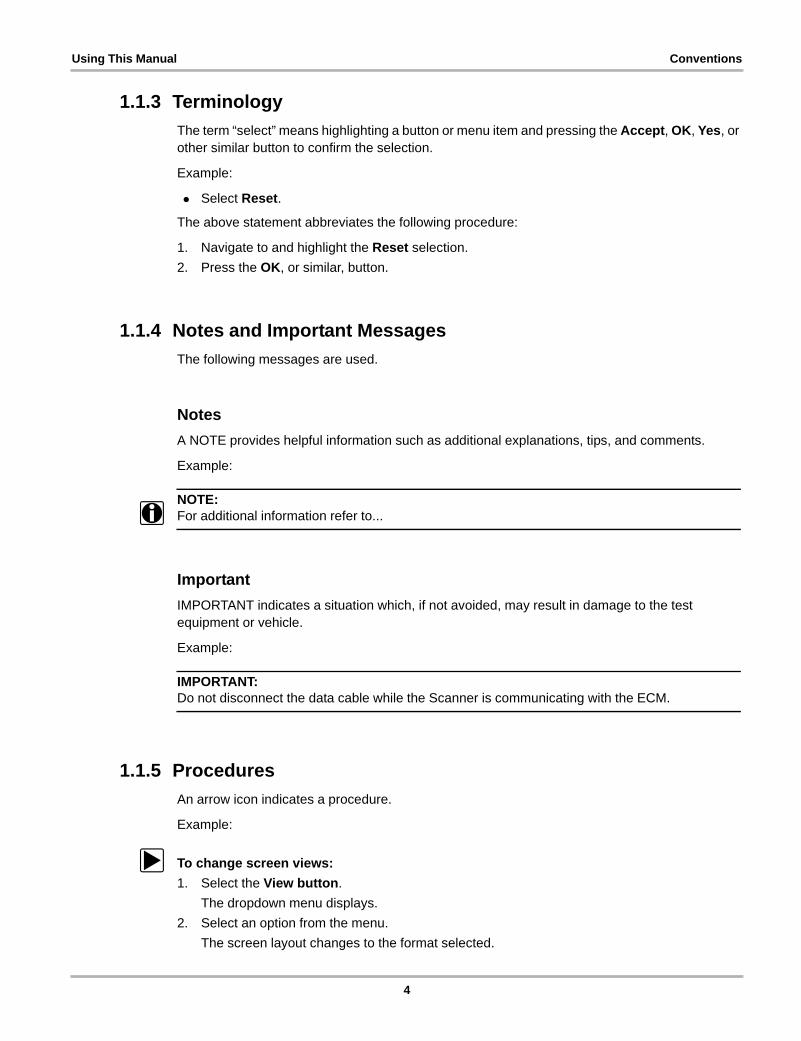
1.1.3 Terminology
The term “select” means highlighting a button or menu item and pressing the Accept, OK, Yes, or other similar button to confirm the selection.
Example:
• Select Reset.
The above statement abbreviates the following procedure:
1. Navigate to and highlight the Reset selection.
2. Press the OK, or similar, button.
1.1.4 Notes and Important Messages
The following messages are used.
Notes
A NOTE provides helpful information such as additional explanations, tips, and comments.
Example:
NOTE:i For additional information refer to...
Important
IMPORTANT indicates a situation which, if not avoided, may result in damage to the test equipment or vehicle.
Example:
IMPORTANT:Do not disconnect the data cable while the Scanner is communicating with the ECM.
1.1.5 Procedures
An arrow icon indicates a procedure.
Example:
z To change screen views:
1. Select the View button.
The dropdown menu displays.
2. Select an option from the menu.
The screen layout changes to the format selected.
4

Chapter 2 Introduction
The Volvo Vehicle Communication Software (VCS) allows your scan tool to test multiple vehicle systems: engine, transmission, antilock brake, and airbag. The tests offered by the software allow for simplified diagnostics and troubleshooting.
The VCS establishes a data link between the scan tool and the electronic control systems of the vehicle being serviced. This data link allows you to view diagnostic trouble codes (DTCs), serial data stream parameters, and freeze-frame information available from the electronic control modules (ECMs) of the vehicle. On models with bi-directional communication, the VCS also lets you perform certain system and functional tests, and provides the ability to switch off the malfunction indicator lamp (MIL) and reset service interval lamps after repairs are made.
The amount and type of information and tests available with the Volvo VCS varies by the year, model, and equipment options of the test vehicle. With the software you can: interpret electronic control module trouble codes, read input and output signals, perform bi-directional tests, test specific systems and components, check the operation of certain actuators (solenoids, valves, and relays), customize your scan tool function, and record and view data movies.
The first two chapters of this manual give an overview of safety and usage conventions. The remainder of this manual is divided into the following chapters:
• Operations, on page 6 explains basic scan tool operations, such as identifying the test vehicle, selecting a system for testing, and connecting the scan tool to the vehicle.
• Testing, on page 11 provides information and procedures for using the scan tool to test specific vehicle control systems.
• Data Parameters, on page 16 provides definitions and operating ranges for the data parameters that display on the scan tool.
• Troubleshooting, on page 32 contains information for troubleshooting problems with scan tool-to-vehicle communications.
• Terms and Acronyms, on page 35 defines common terms and acronyms used throughout this book and in the vehicle communication software on the scan tool.
5

Chapter 3 Operations
This chapter explains how to begin using the basic scan tool test functions, such as identifying the test vehicle, selecting a system for testing, and connecting the scan tool to the vehicle. The flow diagram below represents the basic operation of the vehicle communication software (VCS).
Figure 3-1 Basic scan tool operational flow
ClearCodes
EraseECU Memory
Data
DisplayData List
FunctionalTests
DisplayTests Menu
ReviewECU ID
Display ECUInformation
Codes
DisplayCode List
Select Volvo
Identify Vehicle
Select System
Main Menu
6

Operations Identifying the Test Vehicle
3.1 Identifying the Test VehicleThe test vehicle is identified by entering specific vehicle identification number (VIN) characters into the scan tool. Simply answer a series of questions to configure the scan tool, each response advances the display to the next question. Although specifics may vary slightly based on the year and model of the test vehicle, you are typically asked to provide the following information:
• Model year—tenth VIN character
• Model—fourth and fifth VIN characters
• Engine—sixth and seventh VIN characters
• Optional equipment—appears only when necessary, and requires a yes or no response
A confirmation screen that shows all of the vehicle identification data displays once all of the questions have been answered. From the confirmation screen select:
• Yes to advance to the Select System menu, see “Selecting a System for Testing” on page 7.
• No to move back through the information one step at a time to make corrections.
3.2 Selecting a System for TestingOnce the vehicle identification is confirmed, the Select System menu displays. These menus are specific to the test vehicle and only systems available for that particular vehicle display. Menu options, which vary depending upon the year and model of the vehicle, may include:
• Engine Management
• Transmission
• Antilock Brake
• Airbag
• Service Interval Reset
• Electronic Throttle Module
Selecting a system may open the system main menu, or open additional menus that involve choosing from options available within that category.
3.3 System Main Menu OptionsMain menu options may vary by system, year, and model, but all are similar. Common main menu options ar briefly explained in the following sections. Specific tests available for individual systems, and how to conduct them, are detailed in “Testing” on page 11. The following choices are available on most system main menus:
• Codes
• Clear Codes
• Data
• Functional tests
• Review ECU ID
7

Operations System Main Menu Options
3.3.1 Codes
The codes menu option retrieves diagnostic trouble code (DTC) records stored in the selected ECU. Selecting opens a list of stored DTCs along with a brief description of each code. The DTC list can be saved or printed to be included with your customer records. Exiting the DTC list opens the Codes exit menu.
3.3.2 Clear Codes
This menu option erases DTC records and other temporary information, such as freeze-frame data, from the vehicle ECU under test. Select and follow any on-screen instructions to delete code records from the ECU.
Clear Codes Tips
Keep the following points in mind when clearing codes:
• Some cleared codes only set again under certain circumstances. Note, print, or save the code list before repairs, and before clearing codes.
• When the error condition still exists, the code may set again.
• If the code clearing operation fails for any reason, the previous codes reappear. Should this occur, return to the menu and repeat the Clear Codes operation.
3.3.3 Data
The Data menu option retrieves live serial data from the selected ECU. Selecting Data opens an additional sub-menu, or Data Groups Menu, of viewing options on some models.
Data Groups Menu
Due to the large number of data parameters available on some models, parameters are divided into several smaller groups of related data. Reducing the number of data parameters that display increases the screen update rate, so values displayed on the scan tool refresh much faster.
3.3.4 Functional Tests
Functional tests allow the scan tool to control certain ECU operations. Selecting this menu option opens a sub-menu of choices. Often, there is only one test type available on the sub-menu (usually actuator tests). Possible menu options include:
• Actuator Tests
• Special Functions
• Adaptation
8

Operations System Main Menu Options
Actuator Tests
Actuator Tests allow the scan tool to switch certain system components on and off to check their operation. The number of components that can be activated is dependent on the ECU under test and the vehicle itself.
Typically, the scan tool energizes the selected actuator for 30 seconds, then automatically switches it off to prevent overheating or other damage to the component or system. For most actuators, the test can be cancelled at any time by the operator.
Carefully follow all on-screen messages and instructions while performing functional tests.
Actuator Test Tips
Keep the following points in mind while performing actuator tests:
• Always follow the instructions displayed on the screen.
• Often a certain actuator may not be installed on a vehicle, although according to the manuals it should be. Therefore, first check to make sure the actuator is actually present if you fail to hear a reaction during a test.
• Have the engine running only when instructed to do so by the on-screen instructions.
• Some actuators cannot be stopped during the 30 seconds period, wait for the 30 seconds to elapse to end the test.
• With some engines it is very difficult to hear the fuel-injectors click. Use a multimeter or scope to make sure the injectors are activated properly.
• Some actuators are only activated for a short time, instead of 30 seconds. For example, the fuel-injectors are often activated for only five seconds, this is for safety reasons.
Special Functions
These tests are for resetting the ECU default values after select components have been repaired or replaced. Select an item from the menu and the scan tool displays step-by-step instructions.
Adaptation
These tests are for resetting the ECM adaptive values after select components have been repaired or replaced. Select an item and follow the on-screen instructions.
3.3.5 Review ECU ID
This selection displays pertinent information, such as the part and model numbers and the manufacturer, about the ECU presently communicating with the scan tool.
9

Operations Connecting to a Test Vehicle
3.4 Connecting to a Test VehicleOnce a vehicle has been identified and a system has been selected, a scan tool connection message instructs you to use the vehicle test adapter and a Personality key (if needed) to connect the scan tool for testing. Follow the screen instructions to connect the scan tool to the vehicle.
The test adapter attaches to one end of the data cable, the other end of the data cable attaches to the scan tool. The other end of the adapter fits into the data link connector (DLC) on the test vehicle. A number of Personality keys that fit into the OBD-II adapter are available. Each key allows the scan tool to interpret the data stream information according to the specific configuration of the test vehicle DLC. Always use the key specified in the on-screen instructions.
10

Chapter 4 Testing
This chapter provides information and procedures for using the scan tool to test specific vehicle control systems. The systems discussed in this chapter include:
• Engine Management, on page 11
• Transmission, on page 12
• Antilock Brakes, on page 13
• Airbag, on page 14
• Electronic Throttle Module, on page 15
• Service Interval Reset, on page 15
4.1 Engine ManagementThe main menu option for testing Volvo engine management systems typically include:
• Codes—retrieves diagnostic trouble code (DTC) records stored in the ECU
• Clear Codes—erases DTC records and other temporary information in ECU memory
• Data—retrieves and displays live serial data from the ECU
• Functional Tests—allows the scan tool to control certain ECU operations
• Review ECU ID—displays pertinent information about the ECU
4.1.1 Codes
The codes menu option retrieves diagnostic trouble code (DTC) records stored in the ECU. Selecting opens a list of stored DTCs along with a brief description of each code. Exiting the codes list stops communication with the ECU and returns the display screen to the main menu.
4.1.2 Clear Codes
This menu option erases DTC records and other temporary information, such as freeze-frame data, from the vehicle ECU under test.
z To clear codes:
1. Select Clear Codes from the Engine Management main menu.
A message that the ignition must be on with the engine off displays.
2. Select Yes to continue, selecting No cancels the operation and returns to the main menu.
A “clearing codes” message displays followed by a “clear codes complete” message.
3. Follow the screen instructions to return to the main menu.
4. To verify memory has been cleared, select Codes from the main menu.
11
Testing Transmission
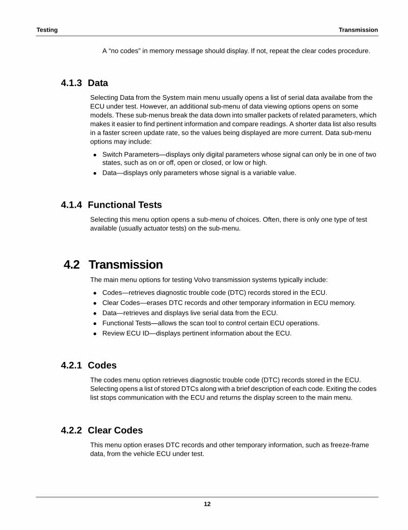
A “no codes” in memory message should display. If not, repeat the clear codes procedure.
4.1.3 Data
Selecting Data from the System main menu usually opens a list of serial data availabe from the ECU under test. However, an additional sub-menu of data viewing options opens on some models. These sub-menus break the data down into smaller packets of related parameters, which makes it easier to find pertinent information and compare readings. A shorter data list also results in a faster screen update rate, so the values being displayed are more current. Data sub-menu options may include:
• Switch Parameters—displays only digital parameters whose signal can only be in one of two states, such as on or off, open or closed, or low or high.
• Data—displays only parameters whose signal is a variable value.
4.1.4 Functional Tests
Selecting this menu option opens a sub-menu of choices. Often, there is only one type of test available (usually actuator tests) on the sub-menu.
4.2 TransmissionThe main menu options for testing Volvo transmission systems typically include:
• Codes—retrieves diagnostic trouble code (DTC) records stored in the ECU.
• Clear Codes—erases DTC records and other temporary information in ECU memory.
• Data—retrieves and displays live serial data from the ECU.
• Functional Tests—allows the scan tool to control certain ECU operations.
• Review ECU ID—displays pertinent information about the ECU.
4.2.1 Codes
The codes menu option retrieves diagnostic trouble code (DTC) records stored in the ECU. Selecting opens a list of stored DTCs along with a brief description of each code. Exiting the codes list stops communication with the ECU and returns the display screen to the main menu.
4.2.2 Clear Codes
This menu option erases DTC records and other temporary information, such as freeze-frame data, from the vehicle ECU under test.
12
Testing Antilock Brakes
z To clear codes:
1. Select Clear Codes from the Transmission main menu.
A message that the ignition must be on with the engine off displays.
2. Select Yes to continue, selecting No cancels the operation and returns to the main menu.
A “clearing codes” message displays followed by a “clear codes complete” message.
3. Follow the screen instructions to return to the main menu.
4. To verify memory has been cleared, select Codes from the main menu.
A “no codes” in memory message should display. If not, repeat the clear codes procedure.
4.2.3 Data
Selecting Data from the main menu usually opens a list of serial data availabe from the ECU under test. However, an additional sub-menu of data viewing options opens on some models.
4.2.4 Functional Tests
Selecting this menu option opens a sub-menu of choices. Often, there is only one type of test available (usually actuator tests) on the sub-menu.
4.3 Antilock BrakesThe main menu options for testing Volvo antilock brake systems typically include:
• Codes—retrieves diagnostic trouble code (DTC) records stored in the ECU.
• Clear Codes—erases DTC records and other temporary information in ECU memory.
• Data—retrieves and displays live serial data from the ECU.
• Functional Tests—allows the scan tool to control certain ECU operations.
• Review ECU ID—displays pertinent information about the ECU.
4.3.1 Codes
The codes menu option retrieves diagnostic trouble code (DTC) records stored in the ECU. Selecting opens a list of stored DTCs along with a brief description of each code. Exiting the codes list stops communication with the ECU and returns the display screen to the main menu.
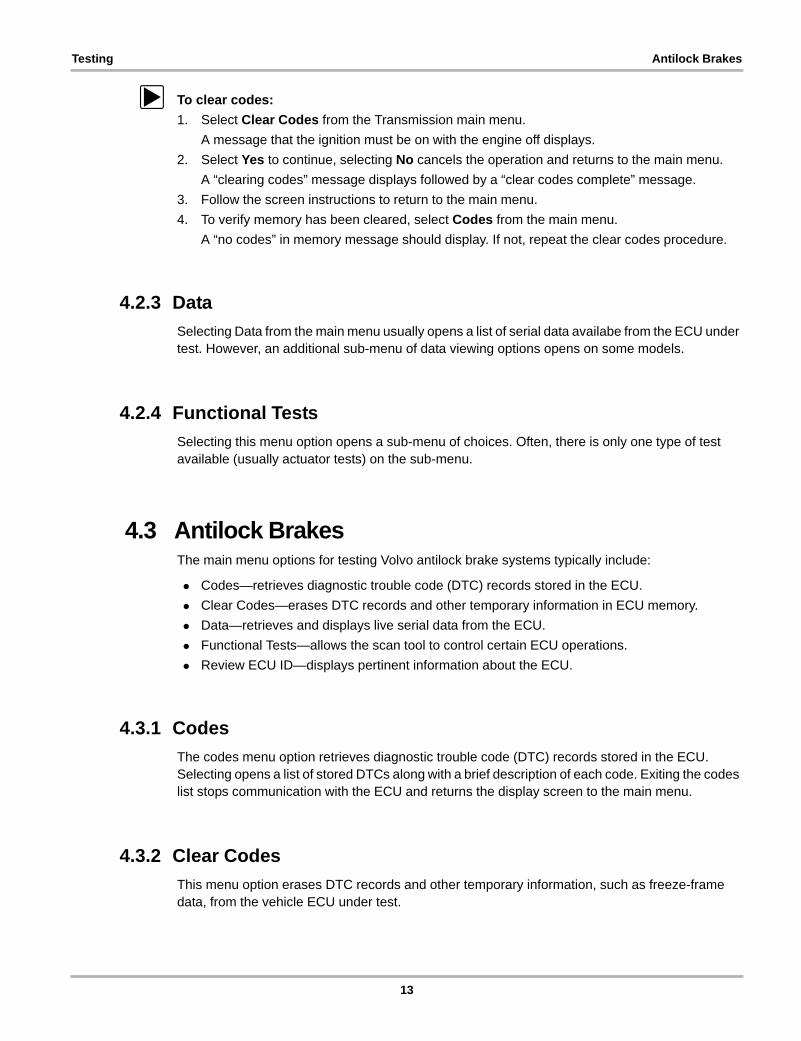
4.3.2 Clear Codes
This menu option erases DTC records and other temporary information, such as freeze-frame data, from the vehicle ECU under test.
13

Testing Airbag
z To clear codes:
1. Select Clear Codes from the ABS main menu.
A message that the ignition must be on with the engine off displays.
2. Select Yes to continue, selecting No cancels the operation and returns to the main menu.
A “clearing codes” message displays followed by a “clear codes complete” message.
3. Follow the screen instructions to return to the main menu.
4. To verify memory has been cleared, select Codes from the main menu.
A “no codes” in memory message should display. If not, repeat the clear codes procedure.
4.3.3 Data
Selecting Data from the menu usually opens a list of serial data availabe from the ECU under test. However, an additional sub-menu of data viewing options opens on some models.
4.3.4 Functional Tests
Selecting this menu option opens a sub-menu of choices. Often, there is only one type of test available (usually actuator tests) on the sub-menu
4.4 AirbagThe main menu options for testing Volvo airbag systems typically include:
• Codes—retrieves diagnostic trouble code (DTC) records stored in the ECU.
• Clear Codes—erases DTC records and other temporary information in ECU memory.
• Data—retrieves and displays live serial data from the ECU.
• Review ECU ID—displays pertinent information about the ECU.
4.4.1 Codes
The codes menu option retrieves diagnostic trouble code (DTC) records stored in the ECU. Selecting opens a list of stored DTCs along with a brief description of each code. Exiting the codes list stops communication with the ECU and returns the display screen to the main menu.
4.4.2 Clear Codes
This menu option erases DTC records and other temporary information, such as freeze-frame data, from the vehicle ECU under test.
14
Testing Electronic Throttle Module
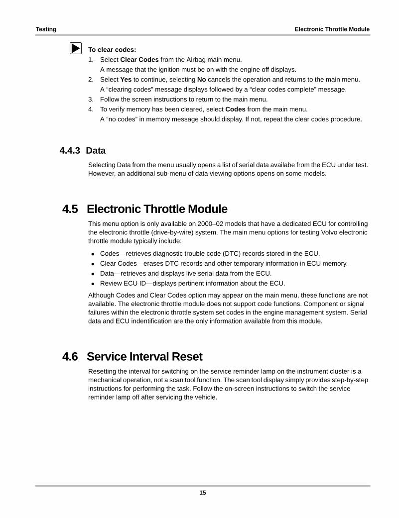
z To clear codes:
1. Select Clear Codes from the Airbag main menu.
A message that the ignition must be on with the engine off displays.
2. Select Yes to continue, selecting No cancels the operation and returns to the main menu.
A “clearing codes” message displays followed by a “clear codes complete” message.
3. Follow the screen instructions to return to the main menu.
4. To verify memory has been cleared, select Codes from the main menu.
A “no codes” in memory message should display. If not, repeat the clear codes procedure.
4.4.3 Data
Selecting Data from the menu usually opens a list of serial data availabe from the ECU under test. However, an additional sub-menu of data viewing options opens on some models.
4.5 Electronic Throttle ModuleThis menu option is only available on 2000–02 models that have a dedicated ECU for controlling the electronic throttle (drive-by-wire) system. The main menu options for testing Volvo electronic throttle module typically include:
• Codes—retrieves diagnostic trouble code (DTC) records stored in the ECU.
• Clear Codes—erases DTC records and other temporary information in ECU memory.
• Data—retrieves and displays live serial data from the ECU.
• Review ECU ID—displays pertinent information about the ECU.
Although Codes and Clear Codes option may appear on the main menu, these functions are not available. The electronic throttle module does not support code functions. Component or signal failures within the electronic throttle system set codes in the engine management system. Serial data and ECU indentification are the only information available from this module.
4.6 Service Interval ResetResetting the interval for switching on the service reminder lamp on the instrument cluster is a mechanical operation, not a scan tool function. The scan tool display simply provides step-by-step instructions for performing the task. Follow the on-screen instructions to switch the service reminder lamp off after servicing the vehicle.
15

Chapter 5 Data Parameters
The following chapters provide definitions and operating ranges for the data parameters that display on the scan tool.
The scan tool displays all of the operating parameters available from the electronic control module of the vehicle, which provides two basic kinds of parameters:
• Digital (discrete) parameters are those that can be in only one of two states, such as on or off, open or closed, high or low, rich or lean, and yes or no. Switches, relays, and solenoids are examples of devices that provide discrete parameters on the data list.
• Analog parameters are displayed as a measured value in the appropriate units such as voltage, pressure, temperature, time, and speed parameters. These display as numbers that vary through a range of values in units, such as pounds per square inch (psi), kilopascal (kPa), degrees Celsius (°C) or Fahrenheit (°F), kilometers per hour (KPH), or miles per hour (MPH).
The scan tool displays some data parameters in numbers that range from 0 to 100, 0 to 255, or 0 to 1800 because that is the maximum number range that the control module transmits for a given parameter. However, many parameter readings never reach the highest possible number. For example, you never see a vehicle speed parameter reading of 255 MPH.
The range of a parameter often varies by year, model, and engine, but typical sampled values observed under actual test conditions are in the parameter description when available.
Parameters may also be identified as input signals or output commands.
• Input or feedback parameters are signals from various sensors and switches to the ECM. They may display as analog or discrete values, depending on the type of input device.
• Output parameters are commands that the control module transmits to various actuators, such as solenoids and fuel injectors. They are displayed as discrete parameters, analog values, or as a pulse-width modulated (PWM) signal.
In the following chapters, parameters are presented as they appear on the scan tool screen. Often, the same parameter goes by a different name when used on more than one model, engine, or control system. In these instances, all of the applicable parameter names displayed on the scan tool are listed before the description.
NOTE:i The scan tool may display names for some data parameters that differ from names displayed by a
factory tool and other scan tools.
Data parameter descriptions in this manual were created from a combination of sources. For most parameters, basic information was provided by the respective manufacturers, then expanded through research and field testing. For some parameters, no information is currently available.
Always use a graphing meter or a oscilloscope, to further validate the displayed values. If data is corrupted on multiple data parameters, do not assume that the control module may be faulty. This corrupt data may be caused by improper communication between the scan tool and the control module. See the troubleshooting sections of the user manual for the diagnostic tool you are using for more communication problem details.
16
Data Parameters Interpreting Pressure Parameters
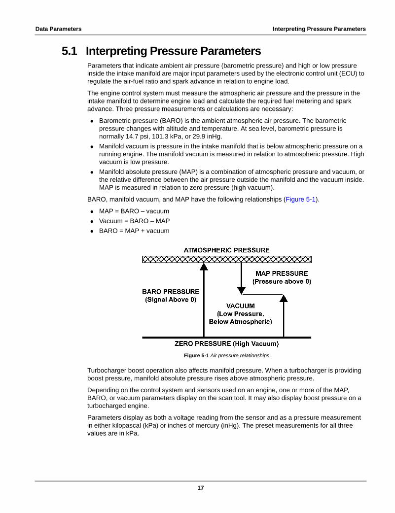
5.1 Interpreting Pressure ParametersParameters that indicate ambient air pressure (barometric pressure) and high or low pressure inside the intake manifold are major input parameters used by the electronic control unit (ECU) to regulate the air-fuel ratio and spark advance in relation to engine load.
The engine control system must measure the atmospheric air pressure and the pressure in the intake manifold to determine engine load and calculate the required fuel metering and spark advance. Three pressure measurements or calculations are necessary:
• Barometric pressure (BARO) is the ambient atmospheric air pressure. The barometric pressure changes with altitude and temperature. At sea level, barometric pressure is normally 14.7 psi, 101.3 kPa, or 29.9 inHg.
• Manifold vacuum is pressure in the intake manifold that is below atmospheric pressure on a running engine. The manifold vacuum is measured in relation to atmospheric pressure. High vacuum is low pressure.
• Manifold absolute pressure (MAP) is a combination of atmospheric pressure and vacuum, or the relative difference between the air pressure outside the manifold and the vacuum inside. MAP is measured in relation to zero pressure (high vacuum).
BARO, manifold vacuum, and MAP have the following relationships (Figure 5-1).
• MAP = BARO – vacuum
• Vacuum = BARO – MAP
• BARO = MAP + vacuum
Figure 5-1 Air pressure relationships
Turbocharger boost operation also affects manifold pressure. When a turbocharger is providing boost pressure, manifold absolute pressure rises above atmospheric pressure.
Depending on the control system and sensors used on an engine, one or more of the MAP, BARO, or vacuum parameters display on the scan tool. It may also display boost pressure on a turbocharged engine.
Parameters display as both a voltage reading from the sensor and as a pressure measurement in either kilopascal (kPa) or inches of mercury (inHg). The preset measurements for all three values are in kPa.
17
Data Parameters Alphabetic List of Parameters
5.2 Alphabetic List of Parameters
AA/C Compressor Active ..................................................................................................................................................22
A/C Compressor Status ..................................................................................................................................................22
A/C Linear Pressure Sensor (V) .....................................................................................................................................22
A/C Pressure ..................................................................................................................................................................22
Pedal Input Signal (V) .....................................................................................................................................................22
Accelerator Pedal Position (%) .......................................................................................................................................22
Accelerator Pedal, Analog Input (%) ..............................................................................................................................22
Accelerator Pedal, PWM Input (%) .................................................................................................................................22
Actual Spark Advance (°) ................................................................................................................................................22
Air Mass (g/s) .................................................................................................................................................................22
Air Mass, Correction Factor ............................................................................................................................................23
Air Temperature (°) .........................................................................................................................................................22
Ambient Air Pressure ......................................................................................................................................................22
Ambient Temperature (°) ................................................................................................................................................22
Ambient Temperature Sensor (V) ...................................................................................................................................23
BBattery Voltage (V) .........................................................................................................................................................23
Boost Pressure ...............................................................................................................................................................23
Brake Light Switch ..........................................................................................................................................................23
Brake Pedal Position (%) ................................................................................................................................................23
Brake Pedal Position Sensor ..........................................................................................................................................23
Brake Switch ...................................................................................................................................................................23
CCamshaft Control Dutycycle, Actual Value .....................................................................................................................23
Camshaft Control Dutycycle, Desired Value ...................................................................................................................23
Camshaft Position Sensor ..............................................................................................................................................23
Clutch Pedal Position (%) ...............................................................................................................................................24
Clutch Pedal Position Sensor (V) ...................................................................................................................................23
Coolant Temp (°) .............................................................................................................................................................24
Coolant Temperature (°) .................................................................................................................................................24
Cooling Fan .................................................................................................................................................................... 24
Cooling Fan, Step 1 .........................................................................................................................................................24
Cooling Fan, Step 2 ........................................................................................................................................................ 24
Cooling Fan, Step 3 ........................................................................................................................................................ 24
Cruise – ..........................................................................................................................................................................24
Cruise + .......................................................................................................................................................................... 24
Cruise Control On/Off-Button .........................................................................................................................................24
Cruise Control Resume ..................................................................................................................................................24
Cruise Control Resume-Button .......................................................................................................................................24
Cruise Control SET – Button .......................................................................................................................................... 24
Cruise Control SET + Button ..........................................................................................................................................24
EEngine Coolant Temperature (°) .....................................................................................................................................24
Engine Coolant Temperature (°) .....................................................................................................................................25
Engine Coolant Temperature (V) ....................................................................................................................................24
18

Data Parameters Alphabetic List of Parameters
Engine Coolant Temperature, Start (°) ............................................................................................................................25
Engine Cooling Fan ........................................................................................................................................................24
Engine Cooling Fan, PWM Controlled (%) .....................................................................................................................25
Engine Speed (rpm) ........................................................................................................................................................25
EVAP Canister Close Valve ............................................................................................................................................25
EVAP Duty Cycle (%) .....................................................................................................................................................25
EVAP-Flow (kg/h) ...........................................................................................................................................................25
FFuel Pressure .................................................................................................................................................................25
Fuel Pump Duty Cycle (%) .............................................................................................................................................25
Fuel Pump Relay ............................................................................................................................................................25
Fuel Rail Pressure ..........................................................................................................................................................25
Fuel Tank Pressure .........................................................................................................................................................25
Fuel Temperature ...........................................................................................................................................................25
GGear Selector Position ....................................................................................................................................................26
IIdle Adaption (%) ............................................................................................................................................................26
Idle Adaption, A/C (%) ....................................................................................................................................................26
Idle Duty Cycle (%) .........................................................................................................................................................26
Ignition Angle (°BTDC) ...................................................................................................................................................26
Ignition Angle ..................................................................................................................................................................26
Ignition Key .....................................................................................................................................................................26
Ignition Key In Pos II .......................................................................................................................................................26
Ignition Key In Pos III ......................................................................................................................................................26
Injection Time .................................................................................................................................................................26
Injection Time, Bank 1 ....................................................................................................................................................26
Injection Time, Bank 2 ....................................................................................................................................................26
Intake Air Temperature (°) ..............................................................................................................................................26
Intake Air Temperature Sensor (V) .................................................................................................................................26
Intake Manifold Absolute Pressure Sensor (pressure) ...................................................................................................27
Intake Manifold Absolute Pressure Sensor (V) ...............................................................................................................27
KKnock Sensor Final Retard Value For All Cylinders .......................................................................................................27
LLambda Control, Bank 1 .................................................................................................................................................27
Lambda Control, Bank 2 .................................................................................................................................................27
Long Term Fuel Trim .......................................................................................................................................................27
Long Term Fuel TRIM Bank 1 .........................................................................................................................................27
Long Term Fuel TRIM Bank 2 .........................................................................................................................................27
Long Term Fuel Trim Data ..............................................................................................................................................27
MMass Air Flow (V) ...........................................................................................................................................................28
Mass Air Flow .................................................................................................................................................................28
Mass Air Flow, Voltage ...................................................................................................................................................28
19

Data Parameters Alphabetic List of Parameters
Misfire Counter 1 ............................................................................................................................................................28
Misfire Counter 2 ............................................................................................................................................................28
Misfire Counter ...............................................................................................................................................................28
Misfire Counter 3 ............................................................................................................................................................28
Misfire Counter 4 ............................................................................................................................................................28
Misfire Counter 5 ............................................................................................................................................................28
Misfire Counter 6 ............................................................................................................................................................28
Misfire Counter 7 ............................................................................................................................................................28
Misfire Counter 8 ............................................................................................................................................................28
Misfire Counter Catalyst Damage, Total .........................................................................................................................28
Misfire Counter Emissions Related, Total .......................................................................................................................28
NNominal Throttle Angle (%) ............................................................................................................................................28
OOil Pressure Switch ........................................................................................................................................................28
Outside Temperature (°) .................................................................................................................................................22
Oxygen Front Sensor, Bank 1 (V) ...................................................................................................................................29
Oxygen Front Sensor, Bank 2 (V) ...................................................................................................................................29
Oxygen Rear Sensor, Bank 1 (V) ...................................................................................................................................29
Oxygen Rear Sensor, Bank 2 (V) ...................................................................................................................................29
Oxygen Sensor Front Heater, Resistance (Ohms) .........................................................................................................29
Oxygen Sensor Front, Element Current (ma) .................................................................................................................29
Oxygen Sensor Front, Signal (Lambda) (V) ...................................................................................................................29
Oxygen Sensor Signal, Rear (V) ....................................................................................................................................29
PPurge Flow (liters/min) ....................................................................................................................................................29
Purge Valve Duty Cycle (%) ...........................................................................................................................................29
Purge-Valve On Duty Time (usec) ..................................................................................................................................29
RRear Oxygen Sensor, Bank 1 (V) ...................................................................................................................................29
Rear Oxygen Sensor, Bank 2 (V) ...................................................................................................................................29
SShort Term Fuel Trim ......................................................................................................................................................30
Short Term Fuel TRIM Bank 1 ........................................................................................................................................30
Short Term Fuel TRIM Bank 2 ........................................................................................................................................30
Short Term Fuel Trim Data .............................................................................................................................................30
Starter Relay ...................................................................................................................................................................30
Supply, 5V (V) .................................................................................................................................................................30
TThrottle Angle (%) ...........................................................................................................................................................30
Throttle Angle, Actual Value (%) .....................................................................................................................................30
Throttle Angle, Desired Value (%) ..................................................................................................................................30
Throttle Position (%) .......................................................................................................................................................30
Throttle Position Sensor, Potentiometer (V) ...................................................................................................................31
Throttle Position Sensor, Potentiometer 1 (V) ................................................................................................................31
20

Data Parameters Alphabetic List of Parameters
Throttle Position Sensor, Potentiometer 2 (V) ................................................................................................................31
Throttle Position, Circuit 1 (%) ........................................................................................................................................30
Throttle Position, Circuit 2 (%) ........................................................................................................................................30
Turbo Control Valve Duty Cycle (%) ...............................................................................................................................31
VVehicle Speed .................................................................................................................................................................31
21

Data Parameters Parameter Definitions
5.3 Parameter DefinitionsA/C Compressor ActiveA/C Compressor Status
Range: ____________________________________________________________On/Off
Indicates the state of the A/C compressor clutch.
A/C Linear Pressure Sensor (V)Range: ________________________________________________________ 0.0 to 5.0 V
Indicates the signal voltage of the A/C linear pressure sensor.
A/C PressureRange: __________________________________________________________ variable
Indicates the PCM calculated refrigerant pressure based on the voltage signal from the A/C high-side pressure sensor. The value reflects the load that the A/C compressor is placing on the engine. Typically, readings are slightly low when pressure is decreasing and slightly high when pressure is increasing. The value is used to adjust idle and control the cooling fans.
Accelerator Pedal Input Signal (V)Range: ________________________________________________________ 0.0 to 5.0 V
Indicates the accelerator pedal position (APP) as voltage. Typical readings are:
• About 0.35–0.95 V at idle
• Above 4.0 V at wide open throttle
Accelerator Pedal, Analog Input (%)Accelerator Pedal Position (%)
Range: _________________________________________________________ 0 to 100%
Indicates the accelerator pedal position as a percentage. Readings are low at closed throttle and increase as the pedal is depressed. The value should increase smoothly as the accelerator pedal moves from closed to full throttle.
Accelerator Pedal, PWM Input (%)Range: _________________________________________________________ 0 to 100%
Indicates the duty cycle of the pulse-width modulated accelerator pedal position sensor.
Actual Spark Advance (°)Range: __________________________________________________________ variable
Indicates the actual amount if ignition timing advance being applied by the PCM.
Air Mass (g/s)Range: __________________________________________________________ variable
Indicates the flow rate of the intake air entering the engine. The display shows airflow volume as grams-per-second.
Air Temperature (°)Ambient Temperature (°)Outside Temperature (°)
Range: _________________________________________ –40 to 389°F or –40 to 199°C
Displays PCM calculated ambient air temperature based on the signal of a temperature sensor. A fixed reading of –40°F or –40°C indicates an open sensor circuit. A fixed reading of 419°F or 215°C indicates a shorted sensor circuit.
Ambient Air PressureRange: __________________________________________________________ variable
Indicates the PCM calculated A/C ambient air pressure.
22
Data Parameters Parameter Definitions
Ambient Temperature Sensor (V)Range: ________________________________________________________ 0.0 to 5.1 V
Indicates the voltage signal from the ambient temperature sensor being input to the PCM. Sensor voltage and temperature are inversely related. A low temperature produces a high voltage signal, and a high temperature produces a low voltage signal.
Air Mass, Correction FactorRange: __________________________________________________________ variable
Indicates mass air flow correction being applied.
Battery Voltage (V)Range: _______________________________________________________ 0.0 to16.0 V
Indicates vehicle battery voltage. The reading should be close to normal charging system regulated voltage with the engine running. This is typically 13.5 to 14.5 V at idle. Check the reading against actual voltage measured at the battery or alternator. Check vehicle specifications for exact values.
Boost PressureRange: __________________________________________________________ variable
Indicates the amount of turbocharger boost pressure.
Brake Light SwitchRange: ____________________________________________________________On/Off
Indicates the brake light switch status.
Brake Pedal Position (%)Range: _________________________________________________________ 0 to 100%
Indicates the brake pedal position as a percentage. The value should increase smoothly as the brake pedal moves through its range of travel.
Brake Pedal Position SensorRange: ________________________________________________________ 0.0 to 5.0 V
Indicates the brake pedal position sensor signal voltage being input to the PCM.
Brake SwitchRange: ____________________________________________________________On/Off
Indicates the brake switch status.
Camshaft Control Dutycycle, Actual ValueRange: _________________________________________________________ 0 to 100%
Indicates the actual duty cycle of the variable camshaft timing control solenoid valve. It reflects the drive percentage being applied to make the actuator achieve a target angle.
Camshaft Control Dutycycle, Desired ValueRange: _________________________________________________________ 0 to 100%
Indicates the desired duty cycle of the variable camshaft timing control solenoid valve. It reflects the target angle the PCM is attempting to achieve.
Camshaft Position SensorRange: __________________________________________________________ variable
Indicates the status of the camshaft position (CMP) sensor signal.
Clutch Pedal Position Sensor (V)Range: ________________________________________________________ 0.0 to 5.0 V
Indicates the clutch pedal position sensor signal voltage being input to the PCM.
23

Data Parameters Parameter Definitions
Clutch Pedal Position (%)Range: _________________________________________________________ 0 to 100%
Indicates the clutch pedal position as a percentage. The value should increase smoothly as the clutch pedal moves through its range of travel.
Coolant Temperature (°)Coolant Temp (°)Engine Coolant Temperature (°)
Range: __________________________________________________________ variable
Indicates the ECM calculated engine coolant temperature (ECT) in degrees based on the ECT sensor signal. The sensor is a thermistor installed in the engine coolant passages.
Typical readings for a fully warmed engine running at idle are 185° to 220°F (85° to 105°C). A reading of –40°C or –40°F may indicate an open in the sensor or the sensor circuit. A reading above 185°C or 366°F may indicate a short in the sensor or the sensor circuit.
Cooling FanCooling Fan, Step 1Cooling Fan, Step 2Cooling Fan, Step 3Engine Cooling Fan
Range: __________________________________________________________ ON/OFF
Indicates the ECM command to operate the radiator cooling fan. The Step 1, Step 2, and Step 3 parameters refer to a single fan with multiple speed settings.
Cruise Control On/Off-ButtonRange: ____________________________________________________________On/Off
Indicates the status of the cruise control On/Off switch, it reads on when the switch is turned on and electrically closed.
Cruise Control ResumeCruise Control Resume-Button
Range: ____________________________________________________________On/Off
Indicates the status of the cruise control resume switch, it reads on when the switch is turned on and electrically closed.
Cruise Control SET + ButtonCruise +
Range: ____________________________________________________________On/Off
Indicates the status of the cruise control accelerate switch, it reads on when the switch is turned on and electrically closed.
Cruise Control SET – ButtonCruise –
Range: ____________________________________________________________On/Off
Indicates the status of the cruise control decelerate switch, it reads on when the switch is turned on and electrically closed.
Engine Coolant Temperature (V)Range: ________________________________________________________ 0.0 to 5.1 V
Indicates the voltage signal from the engine coolant temperature (ECT) sensor. Sensor voltage and temperature are inversely related. A low temperature produces a high voltage signal, and a high temperature produces a low voltage signal.
24

Data Parameters Parameter Definitions
Engine Coolant Temperature (°)Range: _________________________________________ –40 to 199°C or –40 to 389°F
Indicates the ECM calculated engine coolant temperature (ECT) in degrees based on the ECT sensor signal. The sensor is a thermistor installed in the engine coolant passages.
Typical readings for a fully warmed engine running at idle are 185° to 220°F (85° to 105°C). A reading of -40°C or -40°F may indicate an open in the sensor or the sensor circuit. A reading above 185°C or 366°F may indicate a short in the sensor or the sensor circuit.
Engine Coolant Temperature, Start (°)Range: _________________________________________ –40 to 199°C or –40 to 389°F
Indicates what the engine coolant temperature (ECT) was when the engine was started.
Engine Cooling Fan, PWM Controlled (%)Range: _________________________________________________________ 0 to 100%
Indicates the duty cycle of the signal being applied to the engine cooling fan motor.
Engine Speed (rpm)Range: ___________________________________________________ 0 to engine max.
Indicates engine speed, which is computed internally by the PCM based on reference pulses from system sensors.
EVAP Canister Close ValveRange: ______________________________________________________ Open/Closed
Indicates the state of the evaporative emission control system (EVAP) canister close valve.
EVAP Duty Cycle (%)Range: _________________________________________________________ 0 to 100%
Indicates the duty cycle of the evaporative purge control solenoid valve. This indicates the drive percentage of the purge control solenoid valve when on.
EVAP-Flow (kg/h)Range: __________________________________________________________ variable
Indicates the flow rate of the evaporative emission control system (EVAP). The display shows airflow volume as kilograms-per-hour.
Fuel PressureFuel Rail Pressure
Range: __________________________________________________________ variable
Indicates the ECM calculated fuel rail pressure.
Fuel Pump Duty Cycle (%)Range: _________________________________________________________ 0 to 100%
Indicates the duty cycle of the signal being applied to the fuel pump.
Fuel Pump RelayRange: ____________________________________________________________On/Off
Indicates the fuel pump relay status.
Fuel Tank PressureRange: __________________________________________________________ variable
Indicates the ECM calculated fuel tank pressure based on the fuel tank pressure sensor input.
Fuel TemperatureRange: __________________________________________________________ variable
Indicates the ECM calculated fuel temperature.
25

Data Parameters Parameter Definitions
Gear Selector PositionRange: _________________________________________________________see below
Indicates the gear presently selected according to the selector lever position.
Idle Adaption (%)Range: __________________________________________________________ variable
Indicates the adaptive learned value the PCM is applying to the idle air control (IAC) valve to maintain the desired idle speed.
Idle Adaption, A/C (%)Range: __________________________________________________________ variable
Indicates the adaptive learned value the PCM is applying to the idle air control (IAC) valve to maintain the desired idle speed with the A/C operating.
Idle Duty Cycle (%)Range: ______________________________________________________ –100 to 100%
Indicates the drive percentage being applied to the idle air control (IAC) valve.
Ignition AngleIgnition Angle (°BTDC)
Range: __________________________________________________________ variable
Indicates the ignition timing advance being applied. Typical readings range from 5 to 22° BTDC with the engine running at idle.
Ignition KeyRange: _____________________________________________________________0 to 4
Indicates the position of the key in the ignition switch.
Ignition Key In Pos IIRange: ____________________________________________________________On/Off
Indicates whether the ignition key is turned to position II in the ignition switch.
Ignition Key In Pos IIIRange: ____________________________________________________________On/Off
Indicates whether the ignition key is turned to position III in the ignition switch.
Injection TimeInjection Time, Bank 1Injection Time, Bank 2
Range: __________________________________________________________ variable
Indicates the amount of time the PCM commands each injector on during an engine cycle in either milliseconds or nanoseconds. A longer injector pulse width causes more fuel to be delivered. The injector pulse width increases as the engine load increases.
Intake Air Temperature (°)Range: __________________________________________________________ variable
Indicates the intake air temperature (IAT) in degrees. Degree readings are PCM calculated from the IAT sensor signal. Typical ranges are –58°F to 360°F (–50°C to 185°C). Readings should be low on a cold engine and rise as the engine warms up.
Intake Air Temperature Sensor (V)Range: ________________________________________________________ 0.0 to 5.0 V
Indicates the voltage signal from the IAT sensor, which is typically installed in the air cleaner. A 5 V reference signal is applied to the sensor, resistance decreases as temperature increases.
26
Data Parameters Parameter Definitions
Intake Manifold Absolute Pressure Sensor (V)Range: _________________________________________________________ 0 to 5.0 V
Indicates the intake manifold absolute pressure (MAP) sensor signal voltage. Voltage varies with manifold pressure, typical reading are:
• Low when absolute pressure is low (high manifold vacuum).
• High when absolute pressure is high (low manifold vacuum).
Intake Manifold Absolute Pressure Sensor (pressure)Range: __________________________________________________________ variable
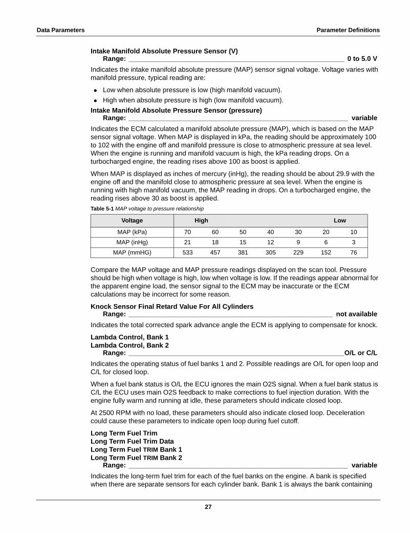
Indicates the ECM calculated a manifold absolute pressure (MAP), which is based on the MAP sensor signal voltage. When MAP is displayed in kPa, the reading should be approximately 100 to 102 with the engine off and manifold pressure is close to atmospheric pressure at sea level. When the engine is running and manifold vacuum is high, the kPa reading drops. On a turbocharged engine, the reading rises above 100 as boost is applied.
When MAP is displayed as inches of mercury (inHg), the reading should be about 29.9 with the engine off and the manifold close to atmospheric pressure at sea level. When the engine is running with high manifold vacuum, the MAP reading in drops. On a turbocharged engine, the reading rises above 30 as boost is applied.
Compare the MAP voltage and MAP pressure readings displayed on the scan tool. Pressure should be high when voltage is high, low when voltage is low. If the readings appear abnormal for the apparent engine load, the sensor signal to the ECM may be inaccurate or the ECM calculations may be incorrect for some reason.
Knock Sensor Final Retard Value For All CylindersRange: ______________________________________________________ not available
Indicates the total corrected spark advance angle the ECM is applying to compensate for knock.
Lambda Control, Bank 1Lambda Control, Bank 2
Range: _________________________________________________________O/L or C/L
Indicates the operating status of fuel banks 1 and 2. Possible readings are O/L for open loop and C/L for closed loop.
When a fuel bank status is O/L the ECU ignores the main O2S signal. When a fuel bank status is C/L the ECU uses main O2S feedback to make corrections to fuel injection duration. With the engine fully warm and running at idle, these parameters should indicate closed loop.
At 2500 RPM with no load, these parameters should also indicate closed loop. Deceleration could cause these parameters to indicate open loop during fuel cutoff.
Long Term Fuel TrimLong Term Fuel Trim DataLong Term Fuel TRIM Bank 1Long Term Fuel TRIM Bank 2
Range: __________________________________________________________ variable
Indicates the long-term fuel trim for each of the fuel banks on the engine. A bank is specified when there are separate sensors for each cylinder bank. Bank 1 is always the bank containing
Table 5-1 MAP voltage to pressure relationship
Voltage High Low
MAP (kPa) 70 60 50 40 30 20 10
MAP (inHg) 21 18 15 12 9 6 3
MAP (mmHG) 533 457 381 305 229 152 76
27

Data Parameters Parameter Definitions
the number 1 cylinder in the firing order. Displayed values represent the operation and long term correction of the fuel mixture on the vehicle. Higher numbers indicate the PCM is commanding a long term rich mixture correction, which increases fuel injector duration. Lower numbers indicate the PCM is commanding a lean mixture, which decreases fuel injector duration.
The long-term fuel trim numbers follow short-term fuel trim numbers to make long term fuel metering corrections, in response to a pattern of short term corrections.
Mass Air FlowRange: __________________________________________________________ variable
Indicates the flow rate of the intake air entering the engine. The display may show airflow volume as kilograms-per-hour (hg/h) or grams-per-second (g/s). Readings may be taken directly from the mass airflow (MAF) sensor, or calculated by the PCM based on input from other sensors.
Mass Air Flow (V)Mass Air Flow, Voltage
Range: ________________________________________________________ 0 to 5.00 V
Indicates mass airflow (MAF), which is the amount of air entering the engine, expressed as voltage. This is the MAF sensor signal, readings should increase along with throttle opening.
Misfire CounterRange: _______________________________________________________actual count
Indicates the accumulated misfire counter.
Misfire Counter 1Misfire Counter 2Misfire Counter 3Misfire Counter 4Misfire Counter 5Misfire Counter 6Misfire Counter 7Misfire Counter 8
Range: _______________________________________________________actual count
Indicates the misfire counter for the indicated cylinder.
Misfire Counter Catalyst Damage, TotalRange: _______________________________________________________actual count
Indicates the accumulated count of misfires severe enough to cause catalytic converter damage.
Misfire Counter Emissions Related, TotalRange: _______________________________________________________actual count
Indicates the accumulated count of emission related misfires.
Nominal Throttle Angle (%)Range: _______________________________________________ Min.: 0%, Max.: 100%
Indicates the ECM calculated nominal throttle opening angle as a percentage.
Oil Pressure SwitchRange: ____________________________________________________________On/Off
Indicates the oil pressure switch status.
28

Data Parameters Parameter Definitions
Oxygen Front Sensor, Bank 1 (V)Oxygen Front Sensor, Bank 2 (V)Oxygen Sensor Front, Signal (Lambda) (V)
Range: ___________________________________________0 to 4.98 V or 0 to 1000 mV
Indicates the signal voltage of the exhaust oxygen sensor (O2S) before the catalyst. The O2S is the primary sensor that indicates whether the engine is running rich or lean. The voltage signal typically ranges from 0 V to 1 V (0 to 1000 millivolts - mV).
A bank is specified when there are separate sensors for each cylinder bank. Bank 1 is always the bank containing the number 1 cylinder in the firing order.
A high signal indicates a rich exhaust; a low signal indicates a lean exhaust. In normal operation, the O2S voltage ranges from 100 to 1000 mV. The O2S must be hot (above 500°F or 260°C), and the system in closed loop before the ECU responds to the sensor signal.
During closed loop operation oxygen sensors should range from 100 mV to 900 mV. A lean condition causes both sensors to read below 400 mV, while a rich condition causes readings above 600 mV. At 2500 RPM O2S readings should switch between high and low at least six times every ten seconds.
Oxygen Rear Sensor, Bank 1 (V)Oxygen Rear Sensor, Bank 2 (V)Oxygen Sensor Signal, Rear (V)Rear Oxygen Sensor, Bank 1 (V)Rear Oxygen Sensor, Bank 2 (V)
Range: ________________________________________________________ 0 to 4.98 V
Indicates the signal voltage of the exhaust oxygen sensor (O2S) after the catalyst. A bank is specified when there are separate sensors for each cylinder bank. Bank 1 is always the bank containing the number 1 cylinder in the firing order. The voltage signal typically ranges from 0 V to 1 V (0 to 1000 millivolts - mV).
Compared to the front sensor, rear sensor voltage fluctuates slowly over a longer period of time due to the oxygen storage capability of an efficiently operating catalyst. If the voltage fluctuates rapidly on a hot catalyst, low catalyst efficiency may be the cause.
Oxygen Sensor Front, Element Current (ma)Range: __________________________________________________________ variable
Indicates the current being applied to the heated oxygen sensor (HO2S) heater circuit.
Oxygen Sensor Front Heater, Resistance (Ohms)Range: __________________________________________________________ variable
Indicates the resistance in ohms of the heated oxygen sensor (HO2S) heater circuit.
Purge Flow (liters/min)Range: __________________________________________________________ variable
Indicates the flow rate of the evaporative emission control system (EVAP). The display shows airflow volume as liters-per-minute.
Purge Valve Duty Cycle (%)Range: _________________________________________________________ 0 to 100%
Indicates the duty cycle of the evaporative purge control solenoid valve. This indicates the drive percentage of the purge control solenoid valve when on.
Purge-Valve On Duty Time (usec)Range: __________________________________________________________ variable
Indicates the amount of time that the evaporative purge control solenoid valve is being energized in nanoseconds.
29

Data Parameters Parameter Definitions
Short Term Fuel TrimShort Term Fuel Trim DataShort Term Fuel TRIM Bank 1Short Term Fuel TRIM Bank 2
Range: __________________________________________________________ variable
Indicates the short-term fuel trim correction for the designated cylinder bank. A bank is specified when there are separate sensors for each cylinder bank. Bank 1 is always the bank containing the number 1 cylinder in the firing order. The short term fuel trim represents a short term correction to fuel delivery by the PCM in response to the amount of time the oxygen sensor (O2S) voltage spends above or below the 450 mV threshold.
Higher readings indicate the PCM is commanding a long-term rich mixture correction, while lower readings indicate the PCM is commanding a lean mixture.
Under certain conditions such as an extended idle and a high ambient temperature, the canister purge may cause the short term fuel trim to read in the negative range during normal operation. The fuel trim values at maximum may indicate an excessively rich or lean system.
Short-term fuel trim leads the long-term trim. When a pattern or trend of short-term corrections to fuel-metering occur, long-term trim responds with a similar correction.
Compare short-term fuel trim readings to injector on-time. Numbers above zero indicate increased on-time, while numbers below zero indicate decreased on-time. Long-term fuel trim corrections operate only in closed loop, in open loop they revert to a fixed value.
Starter RelayRange: __________________________________________________________ ON/OFF
Indicates the state of the starter relay, it reads on when the relay contacts are closed and the starter is engaged.
Supply, 5V (V)Range: ________________________________________________________ 0.0 to 5.0 V
Indicates the status of the reference supply voltage at the ECM.
Throttle Angle (%)Throttle Position (%)Throttle Position, Circuit 1 (%)Throttle Position, Circuit 2 (%)
Range: _______________________________________________ Min.: 0%, Max.: 100%
Indicates the ECM calculated throttle opening as a percentage based on input from the throttle position (TP) sensor signal voltage. Circuit 1 or Circuit 2 in the name indicates the vehicle uses more than one TP sensor.
Typical readings are:
• 0%: with the accelerator pedal released
• 64 to 96%: with the accelerator pedal fully depressed
Throttle Angle, Actual Value (%)Range: _______________________________________________ Min.: 0%, Max.: 100%
Indicates the actual throttle opening as a percentage based on input from the throttle position (TP) sensor signal voltage.
Throttle Angle, Desired Value (%)Range: _______________________________________________ Min.: 0%, Max.: 100%
Indicates the throttle opening that the PCM is attempting to maintain as a percentage.
30

Data Parameters Parameter Definitions
Throttle Position Sensor, Potentiometer (V)Throttle Position Sensor, Potentiometer 1 (V)Throttle Position Sensor, Potentiometer 2 (V)
Range: _________________________________________________________ 0 to 5.0 V
Indicates the throttle position (TP) sensor signal voltage, which determines throttle opening, a 1 or 2 in the name indicates the vehicle uses more than one TP sensor. The full range of the TP sensor voltage readings available to the ECU is 0 to about 5.1 V and readings are usually:
• about 0.5V, closed throttle, engine at idle
• about 4.0V, full throttle, engine under heavy acceleration
Turbo Control Valve Duty Cycle (%)Range: _________________________________________________________ 0 to 100%
Indicates the duty cycle of the turbocharger control solenoid valve.
Vehicle SpeedRange: ___________________________________________________ 0 to vehicle max.
Indicates the PCM calculated vehicle speed in miles-per-hour or kilometers-per-hour based on the vehicle speed sensor (VSS) signal.
31

Appendix A Troubleshooting
A.1 Communication ProblemsVolvo vehicles have few problems communicating with the scan tool. Nevertheless, an electronic control unit (ECU) may fail to communicate with the scan tool. Problems with the wiring or other circuit parts on the vehicle may also prevent communication with the ECU. A vehicle that fails to perform a test may be displaying a symptom of another driveability problem.
A.1.1 Check scan tool operation
If the scan tool works on other vehicles the problem is likely in the vehicle, not the scan tool.
If the display intermittently resets or goes blank, a wire may be opening in one of the cables or in a test adapter. Check for pin-to-pin continuity between the D-shaped connectors at either end of the data cable with an ohmmeter.
A.1.2 Check the Malfunction Indicator Lamp
On some vehicles, the lamp is labeled simply ENGINE, or has a symbol to indicate the ECM. Regardless of the label, they all can be referred to as the malfunction indicator lamp (MIL).
Turn the ignition on and verify that the MIL lights with the ignition on and the engine off. If it does not, troubleshoot and repair the problem before going further. It could be as simple as a burned out lamp bulb or a blown fuse. Refer to the repair manual for the specific vehicle under test to troubleshoot the MIL and its circuitry. Common causes of MIL circuit problems include:
• A blown circuit fuse, (GAUGES or other lamp fuse)
• A burned-out lamp bulb
• A wiring or connector problem
• A defective lamp driver
• A diagnostic connector problem
These vehicles can display a “No Communication” message when there is a communication problem. If the scan tool displays the message, “No Communication”, it means that the scan tool and the control module simply cannot communicate with each other for some reason.
A.1.3 Testing the Diagnostic Connector — 16-pin DLC
All 16-pin OBD-II/EOBD data link connectors (DLCs) may look the same, but most function differently because each vehicle manufacturer interprets the requirements differently. In addition, there may be differences between models and years, and different communication protocols may be used for different systems on the same vehicle. The following table provides general DLC pin information, refer to a wiring diagram for the specific vehicle to troubleshoot DLC problems.
32
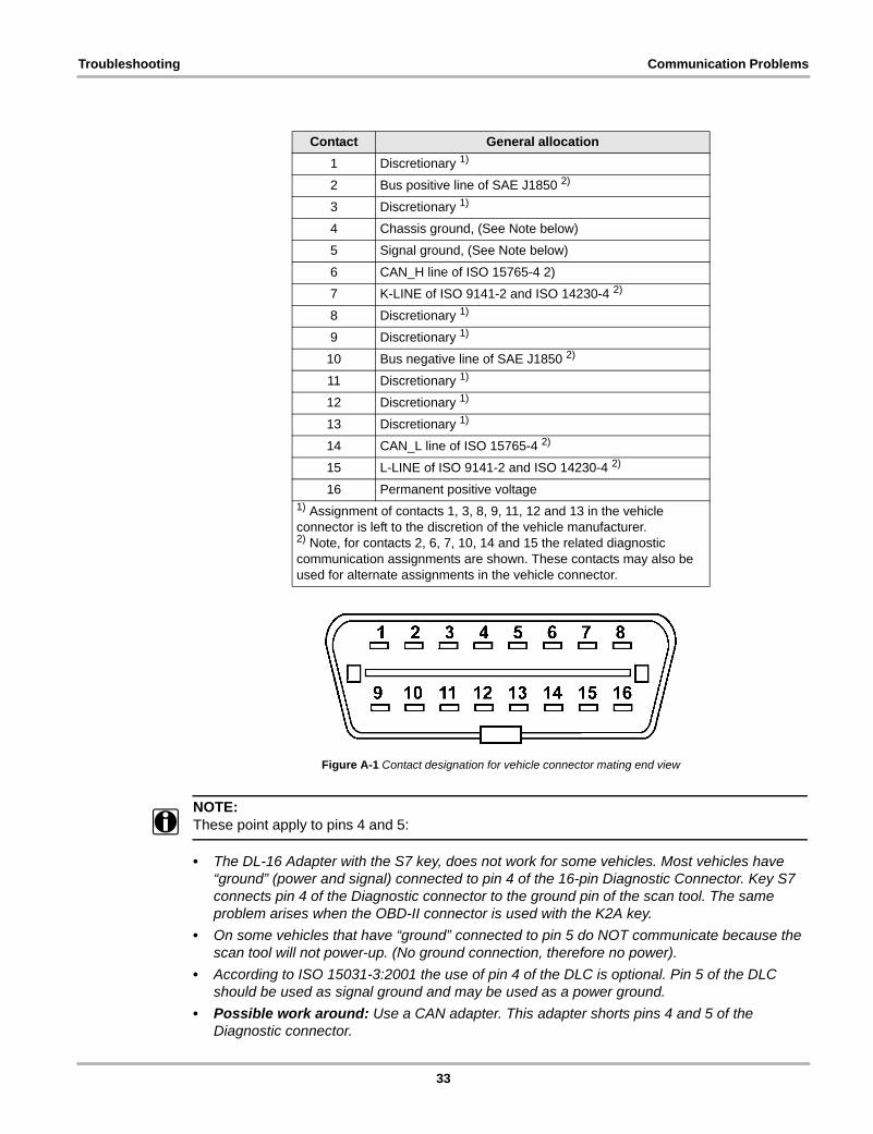
Troubleshooting Communication Problems
Figure A-1 Contact designation for vehicle connector mating end view
NOTE:i These point apply to pins 4 and 5:
• The DL-16 Adapter with the S7 key, does not work for some vehicles. Most vehicles have “ground” (power and signal) connected to pin 4 of the 16-pin Diagnostic Connector. Key S7 connects pin 4 of the Diagnostic connector to the ground pin of the scan tool. The same problem arises when the OBD-II connector is used with the K2A key.
• On some vehicles that have “ground” connected to pin 5 do NOT communicate because the scan tool will not power-up. (No ground connection, therefore no power).
• According to ISO 15031-3:2001 the use of pin 4 of the DLC is optional. Pin 5 of the DLC should be used as signal ground and may be used as a power ground.
• Possible work around: Use a CAN adapter. This adapter shorts pins 4 and 5 of the Diagnostic connector.
Contact General allocation
1 Discretionary 1)
2 Bus positive line of SAE J1850 2)
3 Discretionary 1)
4 Chassis ground, (See Note below)
5 Signal ground, (See Note below)
6 CAN_H line of ISO 15765-4 2)
7 K-LINE of ISO 9141-2 and ISO 14230-4 2)
8 Discretionary 1)
9 Discretionary 1)
10 Bus negative line of SAE J1850 2)
11 Discretionary 1)
12 Discretionary 1)
13 Discretionary 1)
14 CAN_L line of ISO 15765-4 2)
15 L-LINE of ISO 9141-2 and ISO 14230-4 2)
16 Permanent positive voltage1) Assignment of contacts 1, 3, 8, 9, 11, 12 and 13 in the vehicle connector is left to the discretion of the vehicle manufacturer.2) Note, for contacts 2, 6, 7, 10, 14 and 15 the related diagnostic communication assignments are shown. These contacts may also be used for alternate assignments in the vehicle connector.
33
Troubleshooting Communication Problems
Use the following voltage tests at the diagnostic connector to help determine the reason that a vehicle will not perform diagnostic tests. Always use a high-impedance digital voltmeter.
z To test the DLC:
1. Ground — Connect the voltmeter positive (+) lead to the ground terminal in the diagnostic connector. Connect the negative (–) lead directly to the battery negative (–) terminal.
Do not connect the voltmeter negative lead to an engine or chassis ground. This test measures the voltage drop across the ground side of the diagnostic connector. An ideal system ground should have a voltage drop of 0.1 V or less. An open ground can keep a fuel injected engine vehicle from starting. A high-resistance, or “dirty”, ground can cause overall poor operation.
2. Battery Voltage — Connect the voltmeter positive (+) lead to the battery voltage terminal at the diagnostic connector. Connect the negative (–) lead to the battery ground terminal.
The meter should read battery voltage. This tests the battery voltage supply to the ECM.
3. ECM Communication Lines — Remember, a wired pin does not necessarily predict the signal type. First determine if the vehicle uses J1850, ISO 9141, ISO 14230 or CAN (ISO 15765) and then determine if it uses both associated lines, or just one.
For ISO 9141 and ISO 14230 the K-LINE must be used, while the L- LINE is optional. For SAE J1850 the BUS + LINE must be used, while the BUS -LINE is optional.
For CAN (ISO 15765) both the H-LINE and L-LINE are used. Refer to a wiring diagram and use an ohmmeter to check continuity in the J1850, ISO 9141, ISO 14230 or CAN (ISO 15765) circuits to the diagnostic connector. The scan tool uses these lines to communicate with the ECM. If the circuit is open, the scan tool cannot transmit a request to the vehicle ECM nor receive data from it.
34

Appendix B Terms and Acronyms
This appendix defines common terms and acronyms used throughout this book and in the vehicle communication software on the scan tool.
B.1 TermsThe following terms are used throughout this manual to explain certain operations and displays:
B.2 AcronymsThe following acronyms are used in diagnostic trouble code definitions displayed by the scan tool or used in this manual.
code A numerical code, generated by the vehicle control system to indicate a fault has occurred in a particular subsystem, circuit, or part.
cursor The arrow that appears on menus and some other displays. In most displays, the cursor moves as you scroll.
fix To lock a single line of the display in a fixed position on the screen to prevent it from scrolling. Data readings remain live while the parameter categories are fixed.
Flash code A type of vehicle control system that has no serial data. Any trouble codes the control system set are extracted either by flashing the malfunction indicator lamp (MIL) or using a special break-out box.
frame One complete data package, or transmission cycle, from an electronic control module (ECM) that provides serial data of control system operating parameters.
hold To capture and hold a single data frame for review or printing.
movie A vehicle data record whose length depends on the number of selected data parameters.
menu A list of vehicle tests or programs from which a selection can be made.
parameter A measured value of control system input or output operation. Parameters include voltage signals, as well as temperature, pressure, speed, and other data provided by the electronic control module.
release To unlock a fixed line and allow it to scroll.
ABS Antilock Brake System
A/C air-conditioning
AIR secondary air injection
APP accelerator pedal position
ATF automatic transmission fluid
B+ battery positive voltage
35

Terms and Acronyms Acronyms
BARO Barometric pressure
CAN controller area network
CARB California Air Resources Board
CAT catalytic converter
CKP crankshaft position
CMP camshaft position
CO carbon monoxide
CO2 carbon dioxide
Cyl cylinder
DLC data link connector
DOHC dual overhead camshaft
DOT Department of Transportation
DTC diagnostic trouble code
ECM engine control module
ECT engine coolant temperature
ECU engine control unit
EEPROM electrically erasable programmable read only memory
EFI electronic fuel injection
EGR exhaust gas recirculation
EOBD European on-board diagnostics
EPROM erasable programmable read only memory
FTP fuel tank pressure or federal test procedure
HC hydrocarbon
HD heavy duty
Hg mercury
HO2S heated oxygen sensor
Hz Hertz
IAC idle air control
IAT intake air temperature
IC integrated circuit
inHg inches of mercury
KS knock sensor
LCD liquid crystal display
LED light-emitting diode
LEV low emission vehicle
LSD limited-slip differential
MAF mass airflow
MAP manifold absolute pressure
MIL malfunction indicator lamp
mm millimeter
36

Terms and Acronyms Acronyms
mmHg millimeters of mercury
MPI multipoint fuel injection
MPSI multipoint sequential fuel injection
NHTSA National Highway Traffic Safety Administration
O2S oxygen sensor
OBD onboard diagnostics
OBD-II onboard diagnostics two, EPA standardized diagnosis
OHC overhead camshaft
PCM powertrain control module
PNP park/neutral position
PWM pulse-width modulation
SAE Society of Automotive Engineers
SFI sequential fuel injection
SOHC single overhead camshaft
SRS supplemental restraint system
TCC torque converter clutch
TCM transmission control module
TP throttle position
TSB Technical Service Bulletin
ULEV ultra low emission vehicle
V Volts
VIN vehicle identification number
VSS vehicle speed sensor
WOT wide open throttle
37

Index
CCodes and Data
ABS 13–14Airbag 14–15Engine 11–12Transmission 12–13
EElectronic throttle module 15
FFunctional tests
ABS 14Engine 11Transmission 13
MManual conventions
Description 3Notes 4
MessagesSafety i–ii
SSafety i–iiService interval reset 15
38


