62
DOOR CONTROL AND SECURITY HARDWARE
DOOR CONTROL AND SECURITY HARDWARE

2
Table of Contents
3
Electric Strikes
Series 6000 Electric Strikes . . . . . . . . . . . . . . . . . . . . . . . . . . . . . . . . . . . . . . . . . . . . . . . . . . . . . . . . . . . . . . . . . . . . . . . . . 4-11
Strikes for Rim Exit Devices . . . . . . . . . . . . . . . . . . . . . . . . . . . . . . . . . . . . . . . . . . . . . . . . . . . . . . . . . . . . . . . . . . . . . . . 5-6
Strikes for Mortise and Cylindrical Locks . . . . . . . . . . . . . . . . . . . . . . . . . . . . . . . . . . . . . . . . . . . . . . . . . . . . . . . . . . . . 7-11
5100 Electric Strike . . . . . . . . . . . . . . . . . . . . . . . . . . . . . . . . . . . . . . . . . . . . . . . . . . . . . . . . . . . . . . . . . . . . . . . . . . . . . . . . . 12
Compatibility Charts. . . . . . . . . . . . . . . . . . . . . . . . . . . . . . . . . . . . . . . . . . . . . . . . . . . . . . . . . . . . . . . . . . . . . . . . . . . . . . . . . 13
Additional Information . . . . . . . . . . . . . . . . . . . . . . . . . . . . . . . . . . . . . . . . . . . . . . . . . . . . . . . . . . . . . . . . . . . . . . . . . . . . . . . 14
Electrical Accessories
DE5101 . . . . . . . . . . . . . . . . . . . . . . . . . . . . . . . . . . . . . . . . . . . . . . . . . . . . . . . . . . . . . . . . . . . . . . . . . . . . . . . . . . . . . . . . . . 22
Electric Mortise Lock . . . . . . . . . . . . . . . . . . . . . . . . . . . . . . . . . . . . . . . . . . . . . . . . . . . . . . . . . . . . . . . . . . . . . . . . . . . . . . . . 25
Electric Trim . . . . . . . . . . . . . . . . . . . . . . . . . . . . . . . . . . . . . . . . . . . . . . . . . . . . . . . . . . . . . . . . . . . . . . . . . . . . . . . . . . . . . . . 15
Electric Mullions. . . . . . . . . . . . . . . . . . . . . . . . . . . . . . . . . . . . . . . . . . . . . . . . . . . . . . . . . . . . . . . . . . . . . . . . . . . . . . . . . . . . 33
Electrical Power Transfers . . . . . . . . . . . . . . . . . . . . . . . . . . . . . . . . . . . . . . . . . . . . . . . . . . . . . . . . . . . . . . . . . . . . . . . . . . . . 29
Exit Trim - Computer Managed. . . . . . . . . . . . . . . . . . . . . . . . . . . . . . . . . . . . . . . . . . . . . . . . . . . . . . . . . . . . . . . . . . . . . . 26-27
Junction Box . . . . . . . . . . . . . . . . . . . . . . . . . . . . . . . . . . . . . . . . . . . . . . . . . . . . . . . . . . . . . . . . . . . . . . . . . . . . . . . . . . . . . . 29
Monitor Strikes . . . . . . . . . . . . . . . . . . . . . . . . . . . . . . . . . . . . . . . . . . . . . . . . . . . . . . . . . . . . . . . . . . . . . . . . . . . . . . . . . . 30-32
Power Supplies . . . . . . . . . . . . . . . . . . . . . . . . . . . . . . . . . . . . . . . . . . . . . . . . . . . . . . . . . . . . . . . . . . . . . . . . . . . . . . . . . . . . 28
Pushpad. . . . . . . . . . . . . . . . . . . . . . . . . . . . . . . . . . . . . . . . . . . . . . . . . . . . . . . . . . . . . . . . . . . . . . . . . . . . . . . . . . . . . . . . . . 19
Exit Devices
Alarmed Exit Devices . . . . . . . . . . . . . . . . . . . . . . . . . . . . . . . . . . . . . . . . . . . . . . . . . . . . . . . . . . . . . . . . . . . . . . . . . . . . . . 20-21
ALK Exit Alarm Kit. . . . . . . . . . . . . . . . . . . . . . . . . . . . . . . . . . . . . . . . . . . . . . . . . . . . . . . . . . . . . . . . . . . . . . . . . . . . . . . . 23
Chexit Delayed Exit . . . . . . . . . . . . . . . . . . . . . . . . . . . . . . . . . . . . . . . . . . . . . . . . . . . . . . . . . . . . . . . . . . . . . . . . . . . . 20-21
Guard-X. . . . . . . . . . . . . . . . . . . . . . . . . . . . . . . . . . . . . . . . . . . . . . . . . . . . . . . . . . . . . . . . . . . . . . . . . . . . . . . . . . . . . . . . 24
Exit Devices (Electric Latch Retracting) . . . . . . . . . . . . . . . . . . . . . . . . . . . . . . . . . . . . . . . . . . . . . . . . . . . . . . . . . . . . . . . . . . . 16
Exit Devices— Monitoring . . . . . . . . . . . . . . . . . . . . . . . . . . . . . . . . . . . . . . . . . . . . . . . . . . . . . . . . . . . . . . . . . . . . . . . . . 17-19
Additional Information
Handing of Doors. . . . . . . . . . . . . . . . . . . . . . . . . . . . . . . . . . . . . . . . . . . . . . . . . . . . . . . . . . . . . . . . . . . . . . . . . . . . . . . . . . . 34
Wire Size Selection . . . . . . . . . . . . . . . . . . . . . . . . . . . . . . . . . . . . . . . . . . . . . . . . . . . . . . . . . . . . . . . . . . . . . . . . . . . . . . . . . 34
Series 6000 Electric Strikes
4
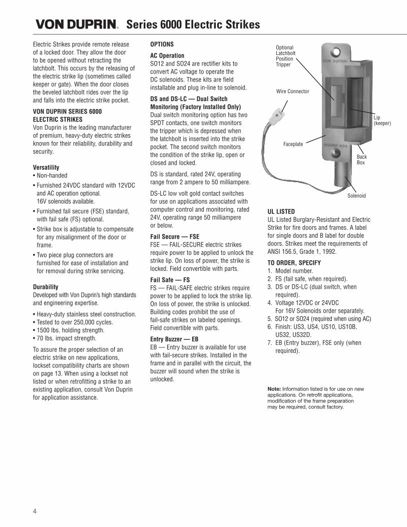
Electric Strikes provide remote release of a locked door. They allow the door to be opened without retracting the latchbolt. This occurs by the releasing ofthe electric strike lip (sometimes calledkeeper or gate). When the door closesthe beveled latchbolt rides over the lipand falls into the electric strike pocket.
VON DUPRIN SERIES 6000 ELECTRIC STRIKESVon Duprin is the leading manufacturerof premium, heavy-duty electric strikesknown for their reliability, durability andsecurity.
Versatility• Non-handed
• Furnished 24VDC standard with 12VDCand AC operation optional. 16V solenoids available.
• Furnished fail secure (FSE) standard,with fail safe (FS) optional.
• Strike box is adjustable to compensatefor any misalignment of the door orframe.
• Two piece plug connectors are furnished for ease of installation andfor removal during strike servicing.
DurabilityDeveloped with Von Duprin’s high standardsand engineering expertise.
• Heavy-duty stainless steel construction.• Tested to over 250,000 cycles.• 1500 lbs. holding strength.• 70 lbs. impact strength.
To assure the proper selection of an electric strike on new applications, lockset compatibility charts are shownon page 13. When using a lockset notlisted or when retrofitting a strike to anexisting application, consult Von Duprinfor application assistance.
OPTIONS
AC OperationSO12 and SO24 are rectifier kits to convert AC voltage to operate the DC solenoids. These kits are field installable and plug in-line to solenoid.
DS and DS-LC — Dual SwitchMonitoring (Factory Installed Only)Dual switch monitoring option has twoSPDT contacts, one switch monitors the tripper which is depressed when the latchbolt is inserted into the strikepocket. The second switch monitors the condition of the strike lip, open orclosed and locked.
DS is standard, rated 24V, operatingrange from 2 ampere to 50 milliampere.
DS-LC low volt gold contact switches for use on applications associated withcomputer control and monitoring, rated24V, operating range 50 milliampere or below.
Fail Secure — FSEFSE — FAIL-SECURE electric strikesrequire power to be applied to unlock thestrike lip. On loss of power, the strike islocked. Field convertible with parts.
Fail Safe — FSFS — FAIL-SAFE electric strikes requirepower to be applied to lock the strike lip.On loss of power, the strike is unlocked.Building codes prohibit the use of fail-safe strikes on labeled openings.Field convertible with parts.
Entry Buzzer — EBEB — Entry buzzer is available for usewith fail-secure strikes. Installed in theframe and in parallel with the circuit, thebuzzer will sound when the strike isunlocked.
UL LISTEDUL Listed Burglary-Resistant and ElectricStrike for fire doors and frames. A labelfor single doors and B label for doubledoors. Strikes meet the requirements ofANSI 156.5, Grade 1, 1992.
TO ORDER, SPECIFY1. Model number.2. FS (fail safe, when required).3. DS or DS-LC (dual switch, when
required).4. Voltage 12VDC or 24VDC
For 16V Solenoids order separately.5. SO12 or SO24 (required when using AC)6. Finish: US3, US4, US10, US10B,
US32, US32D.7. EB (Entry buzzer), FSE only (when
required).
Note: Information listed is for use on newapplications. On retrofit applications, modification of the frame preparationmay be required, consult factory.
OptionalLatchboltPositionTripper
Wire Connector
Faceplate
Solenoid
Back Box
Lip(keeper)
5
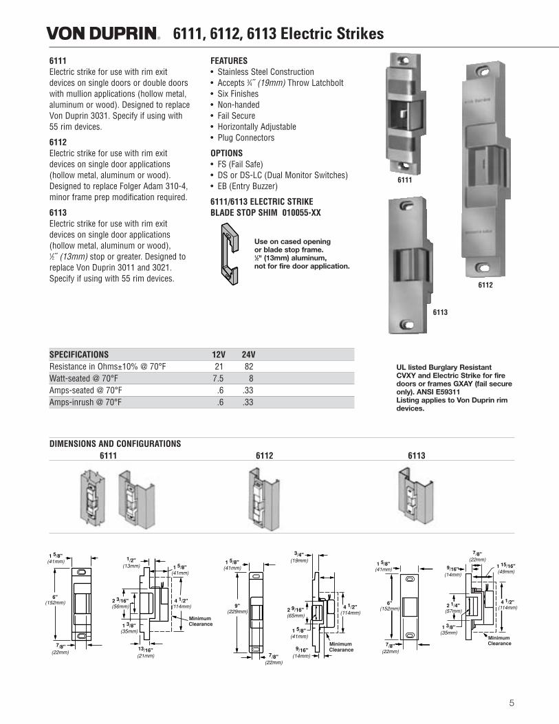
6111Electric strike for use with rim exitdevices on single doors or double doorswith mullion applications (hollow metal,aluminum or wood). Designed to replaceVon Duprin 3031. Specify if using with55 rim devices.
6112Electric strike for use with rim exitdevices on single door applications (hollow metal, aluminum or wood).Designed to replace Folger Adam 310-4,minor frame prep modification required.
6113Electric strike for use with rim exitdevices on single door applications (hollow metal, aluminum or wood), 1⁄2˝ (13mm) stop or greater. Designed toreplace Von Duprin 3011 and 3021.Specify if using with 55 rim devices.
FEATURES• Stainless Steel Construction• Accepts 3⁄4˝ (19mm) Throw Latchbolt• Six Finishes• Non-handed• Fail Secure• Horizontally Adjustable• Plug Connectors
OPTIONS• FS (Fail Safe)• DS or DS-LC (Dual Monitor Switches)• EB (Entry Buzzer)
6111/6113 ELECTRIC STRIKEBLADE STOP SHIM 010055-XX
Use on cased openingor blade stop frame.1⁄2" (13mm) aluminum,not for fire door application.
6111, 6112, 6113 Electric Strikes
SPECIFICATIONS 12V 24VResistance in Ohms±10% @ 70°F 21 82Watt-seated @ 70°F 7.5 8Amps-seated @ 70°F .6 .33Amps-inrush @ 70°F .6 .33
DIMENSIONS AND CONFIGURATIONS6111 6112 6113
UL listed Burglary ResistantCVXY and Electric Strike for firedoors or frames GXAY (fail secureonly). ANSI E59311Listing applies to Von Duprin rimdevices.
6111
6113
6112
1/2"(13mm)
2 3/16"(56mm)
1 3/8"(35mm)
13/16"(21mm)
1 5/8"(41mm)
4 1/2"(114mm)
Minimum Clearance
1 5/8"(41mm)
9"(229mm)
7/8"(22mm)
3/4"(19mm)
2 9/16"(65mm)
Minimum Clearance 9/16"
(14mm)
4 1/2"(114mm)
1 5/8"(41mm)
7/8"(22mm)
6"(152mm)
1 5/8"(41mm)
Minimum Clearance
7/8"(22mm)
9/16"(14mm)
1 15/16"(49mm)
4 1/2"(114mm)
1 3/8"(35mm)
2 1/4"(57mm)
6"(152mm)
1 5/8"(41mm)
7/8"(22mm)
6114, 6121 Electric Strikes
6
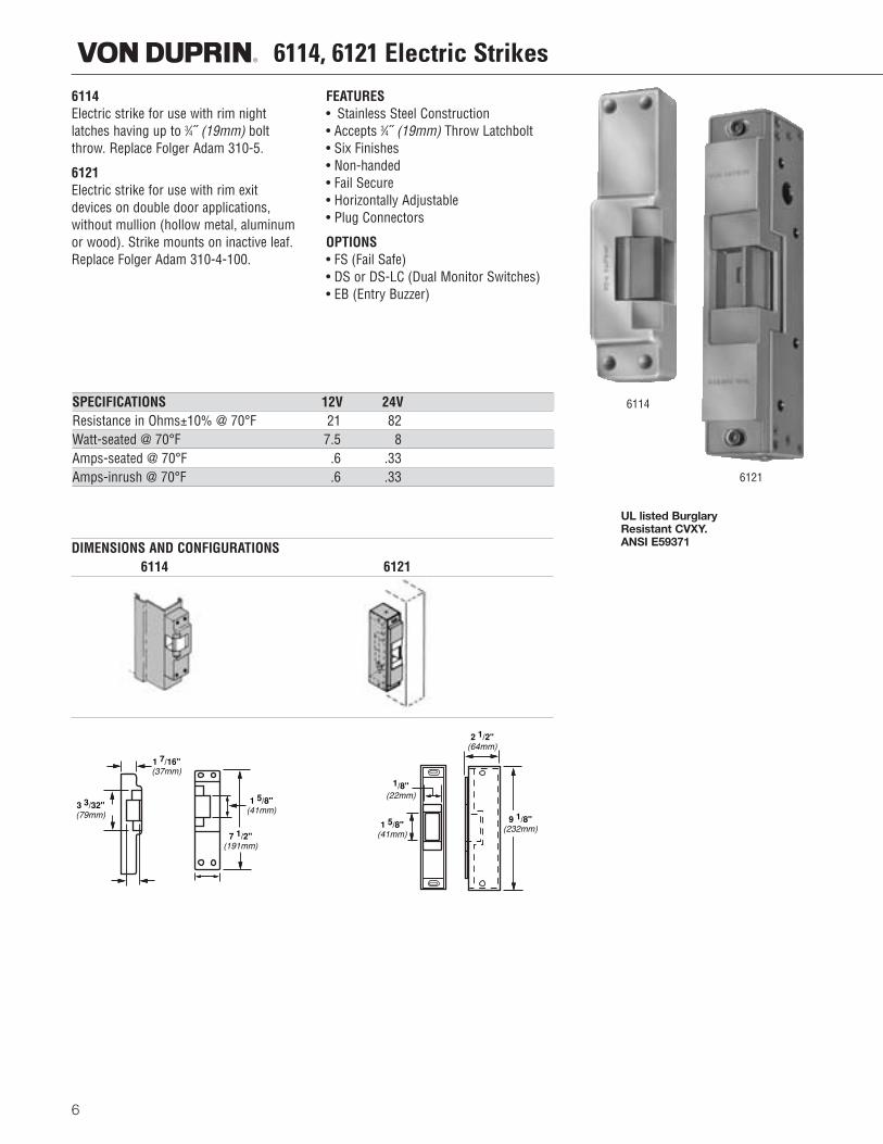
6114Electric strike for use with rim nightlatches having up to 3⁄4˝ (19mm) boltthrow. Replace Folger Adam 310-5.
6121Electric strike for use with rim exitdevices on double door applications,without mullion (hollow metal, aluminumor wood). Strike mounts on inactive leaf.Replace Folger Adam 310-4-100.
FEATURES• Stainless Steel Construction• Accepts 3⁄4˝ (19mm) Throw Latchbolt• Six Finishes• Non-handed• Fail Secure• Horizontally Adjustable• Plug Connectors
OPTIONS• FS (Fail Safe)• DS or DS-LC (Dual Monitor Switches)• EB (Entry Buzzer)
SPECIFICATIONS 12V 24VResistance in Ohms±10% @ 70°F 21 82Watt-seated @ 70°F 7.5 8Amps-seated @ 70°F .6 .33Amps-inrush @ 70°F .6 .33
DIMENSIONS AND CONFIGURATIONS6114 6121
UL listed Burglary Resistant CVXY.ANSI E59371
6114
6121
1 7/16"(37mm)
3 3/32"(79mm)
1/8"(22mm)
1 5/8"(41mm)
1 5/8"(41mm)
7 1/2"(191mm)
2 1/2"(64mm)
9 1/8"(232mm)
6210, 6211, 6211AL, 6211WF Electric Strikes
7
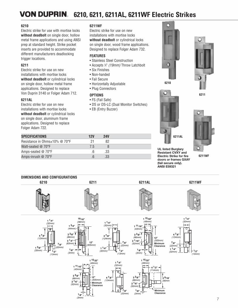
6210Electric strike for use with mortise lockswithout deadbolt on single door, hollowmetal frame applications and using ANSIprep at standard height. Strike pocketinserts are provided to accommodate different manufacturers deadlocking trigger locations.
6211Electric strike for use on new installations with mortise locks without deadbolt or cylindrical locks on single door, hollow metal frame applications. Designed to replace Von Duprin 3140 or Folger Adam 712.
6211ALElectric strike for use on new installations with mortise locks without deadbolt or cylindrical locks on single door, aluminum frame applications. Designed to replace Folger Adam 722.
6211WFElectric strike for use on new installations with mortise locks without deadbolt or cylindrical locks on single door, wood frame applications.Designed to replace Folger Adam 732.
FEATURES• Stainless Steel Construction• Accepts 3⁄4" (19mm) Throw Latchbolt• Six Finishes• Non-handed• Fail Secure• Horizontally Adjustable• Plug Connectors
OPTIONS• FS (Fail Safe)• DS or DS-LC (Dual Monitor Switches)• EB (Entry Buzzer)
SPECIFICATIONS 12V 24VResistance in Ohms±10% @ 70°F 21 82Watt-seated @ 70°F 7.5 8Amps-seated @ 70°F .6 .33Amps-inrush @ 70°F .6 .33
DIMENSIONS AND CONFIGURATIONS6210 6211 6211AL 6211WF
UL listed Burglary Resistant CVXY and Electric Strike for fire doors or frames GXAY (fail secure only).ANSI E59321
6211AL
6211
6211WF
6210
1 1/4"(32mm)
4 7/8"(124mm)
7/8"(22mm)
1/2"(13mm)
1 3/8"(35mm)
1 3/4"(44mm)
3 3/8"(86mm)
3 1/4"(83mm)
1/8"(3mm)
12"(305mm)
19/16"(38mm) 1 1/4"
(32mm)
4 7/8"(124mm)
1 1/4"(32mm) 1/2"
(13mm)
7/8"(22mm)
Minimum Clearance
1 11/16"(43mm)
3 3/8"(86mm)
2 1/16"(52mm)
1/8"(3mm)
1 15/32"(49mm)
12"(305mm)
1 1/4"(32mm)
4 7/8"(124mm)
7/8"(22mm)
1 1/4"(32mm) 1/2"
(13mm)
Minimum Clearance
12"(305mm)
1 15/32"(49mm)
1 11/16"(43mm)
3 3/8"(86mm)2 1/6"
(52mm)
1/8"(3mm)
4 7/8"(124mm)
1 1/4"(32mm)
7/8"(22mm)
3 3/8"(86mm)
2 1/6"(52mm)
1/8"(3mm)
Minimum Clearance
3 9/16"(90mm)
4 1/2"(114mm)
1 15/32"(49mm)
6212, 6212WF Electric Strikes
8
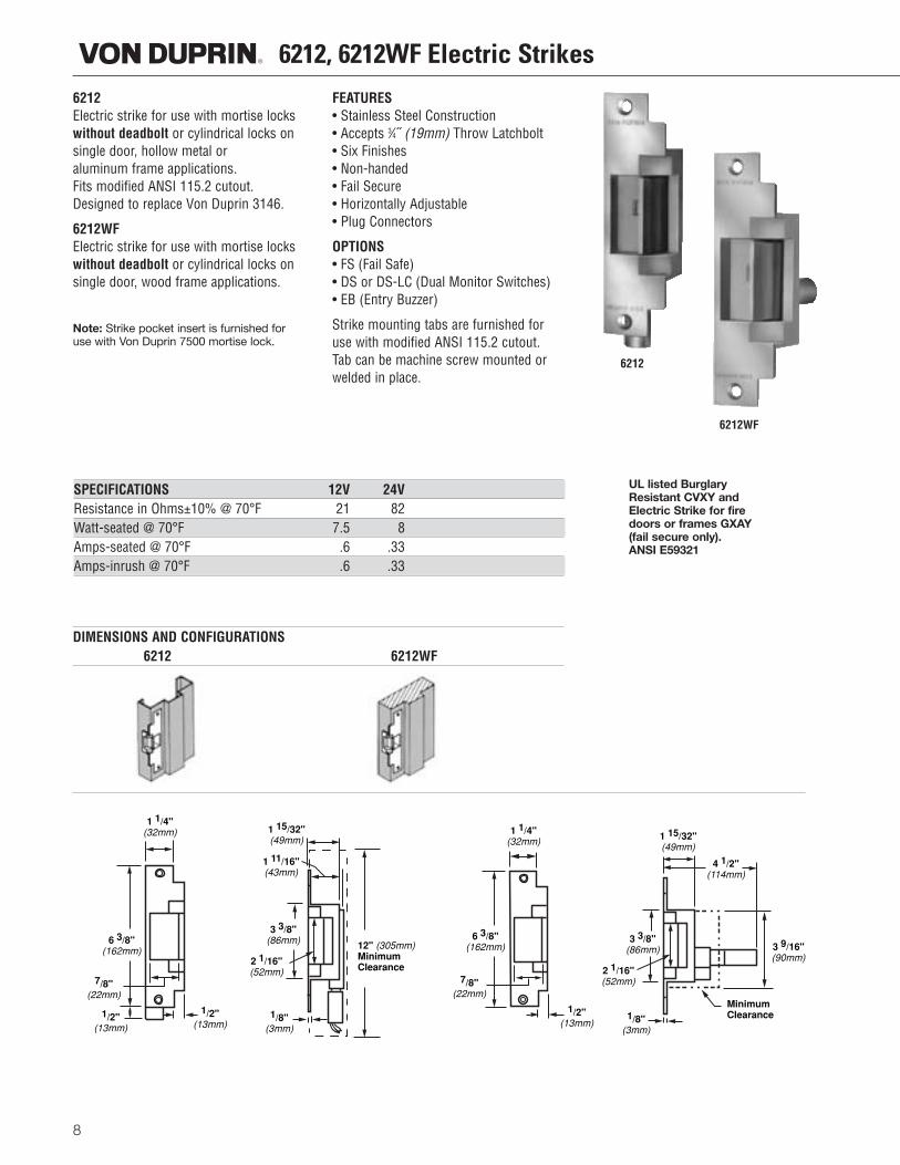
6212Electric strike for use with mortise lockswithout deadbolt or cylindrical locks onsingle door, hollow metal or aluminum frame applications. Fits modified ANSI 115.2 cutout.Designed to replace Von Duprin 3146.
6212WFElectric strike for use with mortise lockswithout deadbolt or cylindrical locks onsingle door, wood frame applications.
Note: Strike pocket insert is furnished foruse with Von Duprin 7500 mortise lock.
FEATURES• Stainless Steel Construction• Accepts 3⁄4˝ (19mm) Throw Latchbolt• Six Finishes• Non-handed• Fail Secure• Horizontally Adjustable• Plug Connectors
OPTIONS• FS (Fail Safe)• DS or DS-LC (Dual Monitor Switches)• EB (Entry Buzzer)
Strike mounting tabs are furnished foruse with modified ANSI 115.2 cutout.Tab can be machine screw mounted orwelded in place.
SPECIFICATIONS 12V 24VResistance in Ohms±10% @ 70°F 21 82Watt-seated @ 70°F 7.5 8Amps-seated @ 70°F .6 .33Amps-inrush @ 70°F .6 .33
DIMENSIONS AND CONFIGURATIONS6212 6212WF
UL listed BurglaryResistant CVXY andElectric Strike for firedoors or frames GXAY(fail secure only).ANSI E59321
6212WF
6212
6 3/8"(162mm)
7/8"(22mm)
1/2"(13mm)
1/2"(13mm)
1 1/4"(32mm) 1 15/32"
(49mm)
1 11/16"(43mm)
3 3/8"(86mm)
2 1/16"(52mm)
1/8"(3mm)
12" (305mm)Minimum Clearance
1 1/4"(32mm)
6 3/8"(162mm)
7/8"(22mm)
1/2"(13mm)
3 3/8"(86mm)
2 1/16"(52mm)
1/8"(3mm)
Minimum Clearance
3 9/16"(90mm)
4 1/2"(114mm)
1 15/32"(49mm)
9"(229mm)
1"(25mm)
3/4"(19mm)
1 3/8"(35mm)
1 5/8"(41mm)
5 3/8"(137mm)
3 3/4"(95mm)
5/32"(4mm)
1 5/8"(41mm)
Minimum Clearance
6 1/8"(156mm)
2 7/8"(73mm)
35/32"(80mm)
6213, 6214, 6215, 6216 Electric Strikes
9
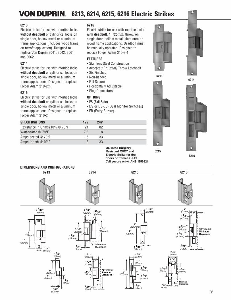
6213Electric strike for use with mortise lockswithout deadbolt or cylindrical locks onsingle door, hollow metal or aluminumframe applications (includes wood frameon retrofit application). Designed toreplace Von Duprin 3041, 3042, 3061and 3062.
6214Electric strike for use with mortise lockswithout deadbolt or cylindrical locks onsingle door, hollow metal or aluminumframe applications. Designed to replaceFolger Adam 310-2 3⁄4.
6215Electric strike for use with mortise lockswithout deadbolt or cylindrical locks onsingle door, hollow metal or aluminumframe applications. Designed to replaceFolger Adam 310-2.
6216Electric strike for use with mortise lockswith deadbolt, 1˝ (25mm) throw, on single door, hollow metal, aluminum orwood frame applications. Deadbolt mustbe manually operated. Designed toreplace Folger Adam 310-3-1.
FEATURES• Stainless Steel Construction• Accepts 3⁄4˝ (19mm) Throw Latchbolt• Six Finishes• Non-handed• Fail Secure• Horizontally Adjustable• Plug Connectors
OPTIONS• FS (Fail Safe)• DS or DS-LC (Dual Monitor Switches)• EB (Entry Buzzer)
SPECIFICATIONS 12V 24VResistance in Ohms±10% @ 70°F 21 82Watt-seated @ 70°F 7.5 8Amps-seated @ 70°F .6 .33Amps-inrush @ 70°F .6 .33
DIMENSIONS AND CONFIGURATIONS6213 6214 6215 6216
UL listed BurglaryResistant CVXY andElectric Strike for firedoors or frames GXAY(fail secure only). ANSI E59321
6213
6215
6214
6216
6"(152mm)
2 3/16"(56mm)
1 "(25mm)
1 1/4"(32mm)
1 1/4"(32mm)
1 3/8"(35mm)
1/4"(6mm)
4 1/2"(114mm)
21/29"(64mm)
3 7/8"(98mm)
MinimumClearance
9"(229mm)
1"(25mm)
1 1/16"(17mm)
1 3/8"(35mm)
2"(51mm)
1 5/8"(41mm)
3 3/4"(95mm)
1 5/8"(41mm)
5/32"(4mm)
12"(305mm)Minimum Clearance
9"(229mm)1"
(25mm)
1 1/16"(17mm)
1 3/8"(35mm)
1 5/8"(41mm)
������(38mm)
������(41mm)
������(95mm)
�����(4mm)
���� (305mm)���������������
6221, 6222, 6225 Electric Strikes
10
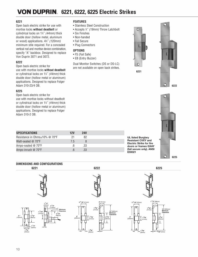
6221Open back electric strike for use withmortise locks without deadbolt or cylindrical locks on 13⁄4˝ (44mm) thickdouble door (hollow metal, aluminum or wood) applications. 43⁄4˝ (120mm)minimum stile required. For a concealedvertical rod and mortise device combination,specify “A” backbox. Designed to replaceVon Duprin 3071 and 3072.
6222Open back electric strike foruse with mortise locks without deadboltor cylindrical locks on 13⁄4˝ (44mm) thickdouble door (hollow metal or aluminum)applications. Designed to replace FolgerAdam 310-23/4 OB.
6225Open back electric strike foruse with mortise locks without deadboltor cylindrical locks on 13⁄4˝ (44mm) thickdouble door (hollow metal or aluminum)applications. Designed to replace FolgerAdam 310-2 OB.
FEATURES• Stainless Steel Construction• Accepts 3⁄4˝ (19mm) Throw Latchbolt• Six Finishes• Non-handed• Fail Secure• Plug Connectors
OPTIONS• FS (Fail Safe)• EB (Entry Buzzer)
Dual Monitor Switches (DS or DS-LC)are not available on open back strikes.
SPECIFICATIONS 12V 24VResistance in Ohms±10% @ 70°F 21 82Watt-seated @ 70°F 7.5 8Amps-seated @ 70°F .6 .33Amps-inrush @ 70°F .6 .33
DIMENSIONS AND CONFIGURATIONS6221 6222 6225
UL listed BurglaryResistant CVXY andElectric Strike for firedoors or frames GXAY(fail secure only). ANSIE59321
6221
6222
6225
6 "(152mm)
3 7/8"(98mm)
1 3/4"(44mm)
1 1/4"(32mm)
MinimumClearance1 7/16"
(37mm)
4 1/2"(114mm)
1 1/4"(32mm)
3 7/8"(98mm)
9"(229mm)
1 5/8"(41mm)
1 3/8"(35mm)
2 1/16"(41mm) 2"(51mm)
1 5/8"(41mm)
3 3/4"(95mm)
12"(305mm)MinimumClearance
1 5/8"(41mm)
1 3/8"(35mm)
9"(229mm)
2 1/16"(22mm)
12"(305mm)MinimumClearance
5/32"(4mm)
3 3/4"(95mm)
1 1/2"(38mm)
1 5/8"(41mm)
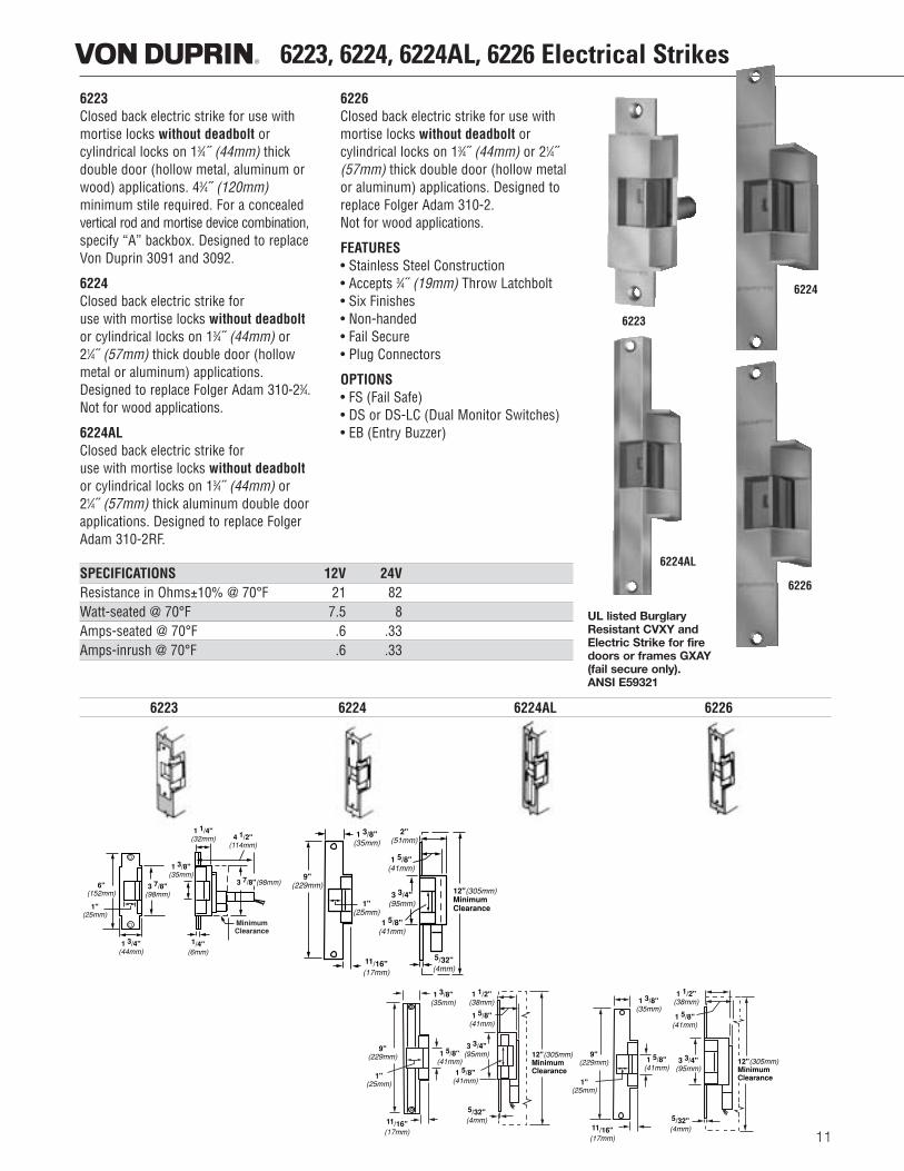
6223, 6224, 6224AL, 6226 Electrical Strikes6223Closed back electric strike for use withmortise locks without deadbolt or cylindrical locks on 13⁄4˝ (44mm) thickdouble door (hollow metal, aluminum orwood) applications. 43⁄4˝ (120mm) minimum stile required. For a concealedvertical rod and mortise device combination,specify “A” backbox. Designed to replaceVon Duprin 3091 and 3092.
6224Closed back electric strike foruse with mortise locks without deadboltor cylindrical locks on 13⁄4˝ (44mm) or21⁄4˝ (57mm) thick double door (hollowmetal or aluminum) applications.Designed to replace Folger Adam 310-23⁄4.Not for wood applications.
6224ALClosed back electric strike foruse with mortise locks without deadboltor cylindrical locks on 13⁄4˝ (44mm) or21⁄4˝ (57mm) thick aluminum double doorapplications. Designed to replace FolgerAdam 310-2RF.
6226Closed back electric strike for use withmortise locks without deadbolt or cylindrical locks on 13⁄4˝ (44mm) or 21⁄4˝(57mm) thick double door (hollow metalor aluminum) applications. Designed toreplace Folger Adam 310-2. Not for wood applications.
FEATURES• Stainless Steel Construction• Accepts 3⁄4˝ (19mm) Throw Latchbolt• Six Finishes• Non-handed• Fail Secure• Plug Connectors
OPTIONS • FS (Fail Safe)• DS or DS-LC (Dual Monitor Switches)• EB (Entry Buzzer)
11
SPECIFICATIONS 12V 24VResistance in Ohms±10% @ 70°F 21 82Watt-seated @ 70°F 7.5 8Amps-seated @ 70°F .6 .33Amps-inrush @ 70°F .6 .33
6223 6224 6224AL 6226
UL listed BurglaryResistant CVXY andElectric Strike for firedoors or frames GXAY(fail secure only).ANSI E59321
6223
6224
6224AL
6226
6"(152mm)
1"(25mm)
1 3/4"(44mm)
3 7/8"(98mm)
MinimumClearance
3 7/8"(98mm)
1 3/8"(35mm)
1 1/4"(32mm) 4 1/2"
(114mm)
1/4"(6mm)
9"(229mm)
1 3/8"(35mm)
1"(25mm)
11/16"(17mm)
5/32"(4mm)
1 5/8"(41mm)
3 3/4"(95mm)
1 5/8"(41mm)
2"(51mm)
12"(305mm)Minimum Clearance
1 3/8"(35mm)
1 5/8"(41mm)
9"(229mm)
1"(25mm)
11/16"(17mm)
1 1/2"(38mm)
1 5/8"(41mm)
3 3/4"(95mm)
1 5/8"(41mm)
5/32"(4mm)
12"(305mm)Minimum Clearance
9"(229mm)
1 3/8"(35mm)
1 5/8"(41mm)
1"(25mm)
11/16"(17mm)
12"(305mm)Minimum Clearance
1 1/2"(38mm)
1 5/8"(41mm)
3 3/4"(95mm)
5/32"(4mm)
12
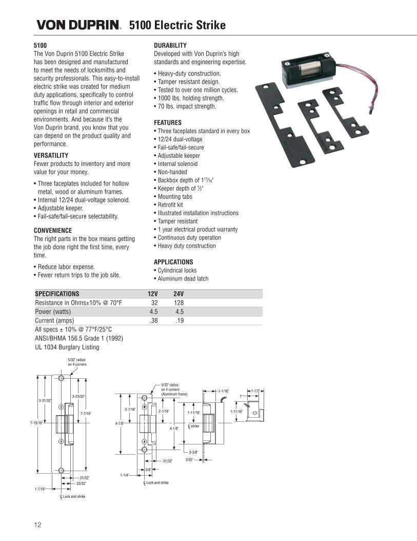
5100 Electric Strike5100The Von Duprin 5100 Electric Strike has been designed and manufactured to meet the needs of locksmiths andsecurity professionals. This easy-to-installelectric strike was created for mediumduty applications, specifically to controltraffic flow through interior and exterioropenings in retail and commercial environments. And because it’s the Von Duprin brand, you know that you can depend on the product quality andperformance.
VERSATILITYFewer products to inventory and morevalue for your money.
• Three faceplates included for hollowmetal, wood or aluminum frames.
• Internal 12/24 dual-voltage solenoid.• Adjustable keeper. • Fail-safe/fail-secure selectability.
CONVENIENCEThe right parts in the box means gettingthe job done right the first time, everytime.
• Reduce labor expense.• Fewer return trips to the job site.
DURABILITYDeveloped with Von Duprin’s high standards and engineering expertise.
• Heavy-duty construction.• Tamper resistant design.• Tested to over one million cycles.• 1000 lbs. holding strength.• 70 lbs. impact strength.
FEATURES• Three faceplates standard in every box• 12/24 dual-voltage• Fail-safe/fail-secure• Adjustable keeper• Internal solenoid • Non-handed• Backbox depth of 111⁄16" • Keeper depth of 1⁄2"• Mounting tabs• Retrofit kit• Illustrated installation instructions• Tamper resistant• 1 year electrical product warranty• Continuous duty operation• Heavy duty construction
APPLICATIONS• Cylindrical locks• Aluminum dead latch
5/32" radiuson 4 corners
2-1/16"2-7/16"
4-7/8"
31/32"
5/8"1-1/4"
3-23/32"
7-7/16"
5/32" radiuson 4 corners(Aluminum frame)
31/32"23/32"
1-7/16"
3-31/32"
7-15/16"
C Lock and strikeL
C Lock and strikeL
C strikeL4-1/8"
3-3/8"
3/32"
1-1/16" 1-1/2"1"
1-11/16" 1-11/16"
SPECIFICATIONS 12V 24VResistance in Ohms±10% @ 70°F 32 128Power (watts) 4.5 4.5Current (amps) .38 .19All specs ± 10% @ 77°F/25°CANSI/BHMA 156.5 Grade 1 (1992)UL 1034 Burglary Listing
13
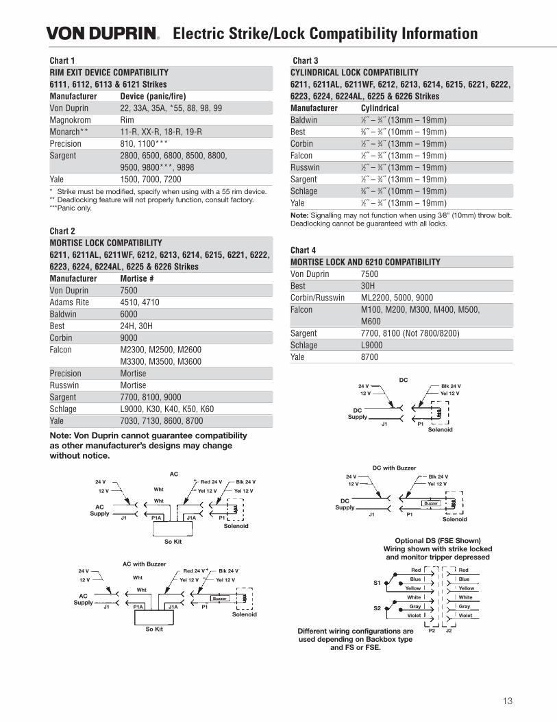
Electric Strike/Lock Compatibility InformationChart 1RIM EXIT DEVICE COMPATIBILITY6111, 6112, 6113 & 6121 StrikesManufacturer Device (panic/fire)Von Duprin 22, 33A, 35A, *55, 88, 98, 99Magnokrom RimMonarch** 11-R, XX-R, 18-R, 19-RPrecision 810, 1100***Sargent 2800, 6500, 6800, 8500, 8800,
9500, 9800***, 9898Yale 1500, 7000, 7200* Strike must be modified, specify when using with a 55 rim device.** Deadlocking feature will not properly function, consult factory.***Panic only.
Chart 2MORTISE LOCK COMPATIBILITY6211, 6211AL, 6211WF, 6212, 6213, 6214, 6215, 6221, 6222,6223, 6224, 6224AL, 6225 & 6226 StrikesManufacturer Mortise #Von Duprin 7500Adams Rite 4510, 4710Baldwin 6000Best 24H, 30HCorbin 9000Falcon M2300, M2500, M2600
M3300, M3500, M3600Precision MortiseRusswin MortiseSargent 7700, 8100, 9000Schlage L9000, K30, K40, K50, K60Yale 7030, 7130, 8600, 8700
Note: Von Duprin cannot guarantee compatibility as other manufacturer’s designs may change without notice.
Chart 3CYLINDRICAL LOCK COMPATIBILITY6211, 6211AL, 6211WF, 6212, 6213, 6214, 6215, 6221, 6222,6223, 6224, 6224AL, 6225 & 6226 StrikesManufacturer CylindricalBaldwin 1⁄2˝ – 3⁄4˝ (13mm – 19mm)Best 3⁄8˝ – 3⁄4˝ (10mm – 19mm)Corbin 1⁄2˝ – 3⁄4˝ (13mm – 19mm)Falcon 1⁄2˝ – 3⁄4˝ (13mm – 19mm)Russwin 1⁄2˝ – 3⁄4˝ (13mm – 19mm)Sargent 1⁄2˝ – 3⁄4˝ (13mm – 19mm)Schlage 3⁄8˝ – 3⁄4˝ (10mm – 19mm)Yale 1⁄2˝ – 3⁄4˝ (13mm – 19mm)Note: Signalling may not function when using 3⁄8" (10mm) throw bolt.Deadlocking cannot be guaranteed with all locks.
Chart 4MORTISE LOCK AND 6210 COMPATIBILITYVon Duprin 7500Best 30HCorbin/Russwin ML2200, 5000, 9000Falcon M100, M200, M300, M400, M500,
M600Sargent 7700, 8100 (Not 7800/8200)Schlage L9000Yale 8700
AC
So Kit
ACSupply
24 V
12 V
Red 24 V
Yel 12 V
Blk 24 V
Yel 12 V
Wht
P1A J1A P1J1
Solenoid
DC
DCSupply
24 V12 V
Blk 24 VYel 12 V
P1J1Solenoid
DC with Buzzer
DCSupply
24 V12 V
Blk 24 VYel 12 V
P1J1Solenoid
AC with Buzzer
So Kit
ACSupply
24 V
12 V
Red 24 V
Yel 12 V
Blk 24 V
Yel 12 V
Wht
P1A J1A P1
Buzzer
J1
Solenoid
Buzzer
Optional DS (FSE Shown)Wiring shown with strike lockedand monitor tripper depressed
Different wiring configurations areused depending on Backbox type
and FS or FSE.
S1
S2
Red
Blue
Yellow
White
Gray
Violet
Red
Blue
Yellow
White
Gray
Violet
P2 J2
Wht
Wht
+
–
+
–
Additional Information
14
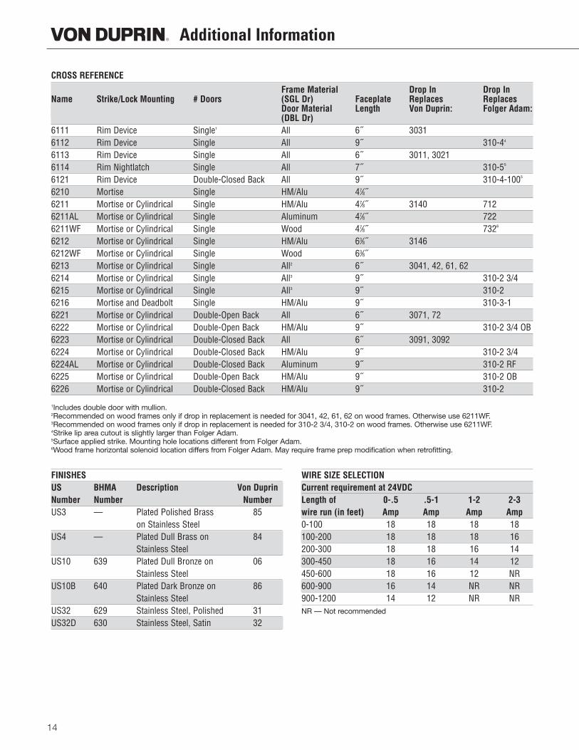
CROSS REFERENCE
Frame Material Drop In Drop InName Strike/Lock Mounting # Doors (SGL Dr) Faceplate Replaces Replaces
Door Material Length Von Duprin: Folger Adam:(DBL Dr)
6111 Rim Device Single1 All 6˝ 30316112 Rim Device Single All 9˝ 310-44
6113 Rim Device Single All 6˝ 3011, 30216114 Rim Nightlatch Single All 7˝ 310-55
6121 Rim Device Double-Closed Back All 9˝ 310-4-1005
6210 Mortise Single HM/Alu 47⁄8˝6211 Mortise or Cylindrical Single HM/Alu 47⁄8˝ 3140 7126211AL Mortise or Cylindrical Single Aluminum 47⁄8˝ 7226211WF Mortise or Cylindrical Single Wood 47⁄8˝ 7326
6212 Mortise or Cylindrical Single HM/Alu 63⁄8˝ 31466212WF Mortise or Cylindrical Single Wood 63⁄8˝6213 Mortise or Cylindrical Single All2 6˝ 3041, 42, 61, 626214 Mortise or Cylindrical Single All3 9˝ 310-2 3/46215 Mortise or Cylindrical Single All3 9˝ 310-26216 Mortise and Deadbolt Single HM/Alu 9˝ 310-3-16221 Mortise or Cylindrical Double-Open Back All 6˝ 3071, 726222 Mortise or Cylindrical Double-Open Back HM/Alu 9˝ 310-2 3/4 OB6223 Mortise or Cylindrical Double-Closed Back All 6˝ 3091, 30926224 Mortise or Cylindrical Double-Closed Back HM/Alu 9˝ 310-2 3/46224AL Mortise or Cylindrical Double-Closed Back Aluminum 9˝ 310-2 RF6225 Mortise or Cylindrical Double-Open Back HM/Alu 9˝ 310-2 OB6226 Mortise or Cylindrical Double-Closed Back HM/Alu 9˝ 310-2
1Includes double door with mullion.2Recommended on wood frames only if drop in replacement is needed for 3041, 42, 61, 62 on wood frames. Otherwise use 6211WF.3Recommended on wood frames only if drop in replacement is needed for 310-2 3/4, 310-2 on wood frames. Otherwise use 6211WF.4Strike lip area cutout is slightly larger than Folger Adam.5Surface applied strike. Mounting hole locations different from Folger Adam.6Wood frame horizontal solenoid location differs from Folger Adam. May require frame prep modification when retrofitting.
FINISHESUS BHMA Description Von DuprinNumber Number NumberUS3 –– Plated Polished Brass 85
on Stainless SteelUS4 –– Plated Dull Brass on 84
Stainless SteelUS10 639 Plated Dull Bronze on 06
Stainless SteelUS10B 640 Plated Dark Bronze on 86
Stainless SteelUS32 629 Stainless Steel, Polished 31US32D 630 Stainless Steel, Satin 32
WIRE SIZE SELECTIONCurrent requirement at 24VDCLength of 0-.5 .5-1 1-2 2-3wire run (in feet) Amp Amp Amp Amp0-100 18 18 18 18100-200 18 18 18 16200-300 18 18 16 14300-450 18 16 14 12450-600 18 16 12 NR600-900 16 14 NR NR900-1200 14 12 NR NRNR — Not recommended
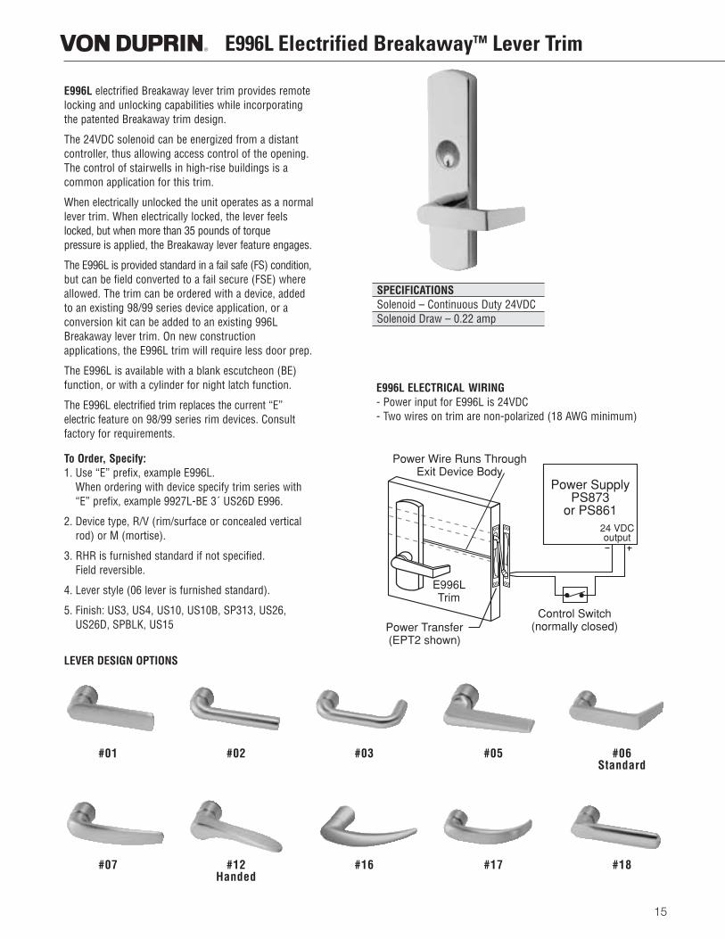
E996L electrified Breakaway lever trim provides remotelocking and unlocking capabilities while incorporatingthe patented Breakaway trim design.
The 24VDC solenoid can be energized from a distantcontroller, thus allowing access control of the opening.The control of stairwells in high-rise buildings is acommon application for this trim.
When electrically unlocked the unit operates as a normallever trim. When electrically locked, the lever feelslocked, but when more than 35 pounds of torque pressure is applied, the Breakaway lever feature engages.
The E996L is provided standard in a fail safe (FS) condition,but can be field converted to a fail secure (FSE) whereallowed. The trim can be ordered with a device, addedto an existing 98/99 series device application, or a conversion kit can be added to an existing 996LBreakaway lever trim. On new construction applications, the E996L trim will require less door prep.
The E996L is available with a blank escutcheon (BE)function, or with a cylinder for night latch function.
The E996L electrified trim replaces the current “E” electric feature on 98/99 series rim devices. Consultfactory for requirements.
To Order, Specify:1. Use “E” prefix, example E996L.
When ordering with device specify trim series with“E” prefix, example 9927L-BE 3´ US26D E996.
2. Device type, R/V (rim/surface or concealed verticalrod) or M (mortise).
3. RHR is furnished standard if not specified. Field reversible.
4. Lever style (06 lever is furnished standard).
5. Finish: US3, US4, US10, US10B, SP313, US26,US26D, SPBLK, US15
E996L Electrified BreakawayTM Lever Trim
15
E996L ELECTRICAL WIRING- Power input for E996L is 24VDC- Two wires on trim are non-polarized (18 AWG minimum)
LEVER DESIGN OPTIONS
SPECIFICATIONSSolenoid – Continuous Duty 24VDCSolenoid Draw – 0.22 amp
#01 #02 #03 #05 #06Standard
#07 #12 #16 #17 #18Handed
Power SupplyPS873
or PS861
Power Transfer(EPT2 shown)
Control Switch(normally closed)
24 VDCoutput
E996LTrim
Power Wire Runs ThroughExit Device Body
Electric Latch Retraction EL
16
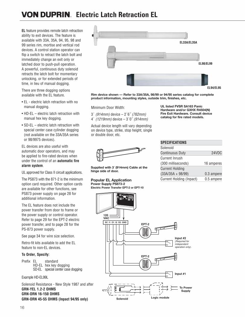
EL feature provides remote latch retractionability to exit devices. The feature isavailable with 33A, 35A, 94, 95, 98 and99 series rim, mortise and vertical roddevices. A control station operator canflip a switch to retract the latch bolt andimmediately change an exit only orlatched door to push-pull operation. A powerful, continuous duty solenoidretracts the latch bolt for momentaryunlocking, or for extended periods oftime, in lieu of manual dogging.
There are three dogging options available with the EL feature.
• EL - electric latch retraction with nomanual dogging.
• HD-EL – electric latch retraction withmanual hex key dogging.
• SD-EL – electric latch retraction withspecial center case cylinder dogging(not available on the 33A/35A series or 98/9975 devices).
EL devices are also useful with automatic door operators, and may be applied to fire-rated devices whenunder the control of an automatic firealarm system.
UL approved for Class II circuit applications.
The PS873 with the 871-2 is the minimumoption card required. Other option cardsare available for other functions, seePS873 power supply on page 28 foradditional information.
The EL feature does not include thepower transfer from door to frame orthe power supply or control operator. Refer to page 29 for the EPT-2 electricpower transfer, and to page 28 for thePS-873 power supply.
See page 34 for wire size selection.
Retro-fit kits available to add the EL feature to non-EL devices.
To Order, Specify:
Prefix EL standardHD-EL hex key doggingSD-EL special center case dogging
Example HD-EL99L
Minimum Door Width:
3´ (914mm) device – 2´6˝ (762mm)4´ (1219mm) device – 3´0˝ (914mm)
Actual device length will vary dependingon device type, strike, stop height, singleor double door, etc.
UL listed FVSR SA163 Panic Hardware and/or GXHX R4504(N) Fire Exit Hardware. Consult device catalog for fire rated models.
SPECIFICATIONSSolenoidContinuous Duty 24VDCCurrent Inrush(300 milliseconds) 16 amperesCurrent Holding (33A/35A + 98/99) 0.3 ampereCurrent Holding (Inpact) 0.5 ampere
Rim device shown — Refer to 33A/35A, 98/99 or 94/95 series catalog for complete product information, mounting styles, outside trim, finishes, etc.
EL33A/EL35A
EL98/EL99
EL94/EL95
Supplied with 3´ (914mm) Cable at thehinge side of door.
Popular EL ApplicationPower Supply PS873-2Electric Power Transfer EPT-2 or EPT-10
Solenoid Resistance - New Style 1987 and afterGRN-YEL 1.2-2 OHMSGRN-ORN 16-150 OHMSGRN-ORN 45-55 OHMS (Inpact 94/95 only) Solenoid
To PowerSupply
Logic module
Signal Switch RX and LX
17
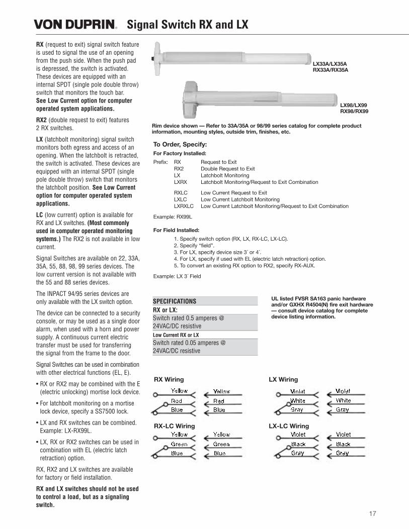
RX (request to exit) signal switch featureis used to signal the use of an openingfrom the push side. When the push padis depressed, the switch is activated.These devices are equipped with aninternal SPDT (single pole double throw)switch that monitors the touch bar.See Low Current option for computeroperated system applications.
RX2 (double request to exit) features 2 RX switches.
LX (latchbolt monitoring) signal switchmonitors both egress and access of anopening. When the latchbolt is retracted,the switch is activated. These devices areequipped with an internal SPDT (singlepole double throw) switch that monitorsthe latchbolt position. See Low Currentoption for computer operated systemapplications.
LC (low current) option is available forRX and LX switches. (Most commonlyused in computer operated monitoringsystems.) The RX2 is not available in lowcurrent.
Signal Switches are available on 22, 33A,35A, 55, 88, 98, 99 series devices. Thelow current version is not available withthe 55 and 88 series devices.
The INPACT 94/95 series devices areonly available with the LX switch option.
The device can be connected to a securityconsole, or may be used as a single dooralarm, when used with a horn and powersupply. A continuous current electrictransfer must be used for transferringthe signal from the frame to the door.
Signal Switches can be used in combinationwith other electrical functions (EL, E).
• RX or RX2 may be combined with the E(electric unlocking) mortise lock device.
• For latchbolt monitoring on a mortiselock device, specify a SS7500 lock.
• LX and RX switches can be combined.Example: LX-RX99L.
• LX, RX or RX2 switches can be used incombination with EL (electric latchretraction) option.
RX, RX2 and LX switches are availablefor factory or field installation.
RX and LX switches should not be usedto control a load, but as a signalingswitch.
Rim device shown — Refer to 33A/35A or 98/99 series catalog for complete product information, mounting styles, outside trim, finishes, etc.
SPECIFICATIONSRX or LX:Switch rated 0.5 amperes @ 24VAC/DC resistiveLow Current RX or LXSwitch rated 0.05 amperes @ 24VAC/DC resistive
UL listed FVSR SA163 panic hardwareand/or GXHX R4504(N) fire exit hardware— consult device catalog for completedevice listing information.
LX98/LX99RX98/RX99
LX33A/LX35ARX33A/RX35A
To Order, Specify:For Factory Installed:
Prefix: RX Request to ExitRX2 Double Request to ExitLX Latchbolt MonitoringLXRX Latchbolt Monitoring/Request to Exit Combination
RXLC Low Current Request to ExitLXLC Low Current Latchbolt MonitoringLXRXLC Low Current Latchbolt Monitoring/Request to Exit Combination
Example: RX99L
For Field Installed:
1. Specify switch option (RX, LX, RX-LC, LX-LC).2. Specify “field”.3. For LX, specify device size 3´ or 4´.4. For LX, specify if used with EL (electric latch retraction) option.5. To convert an existing RX option to RX2, specify RX-AUX.
Example: LX 3´ Field
RX Wiring LX Wiring
RX-LC Wiring LX-LC Wiring
Signal Switch SS
18
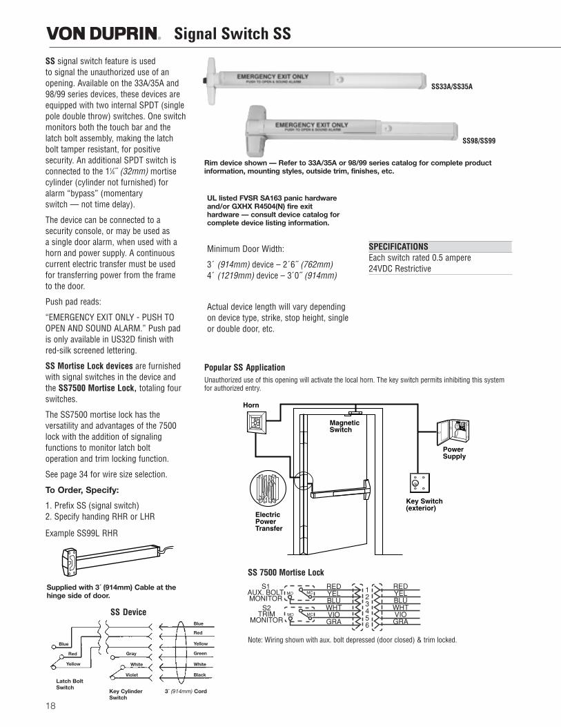
SS signal switch feature is used to signal the unauthorized use of anopening. Available on the 33A/35A and98/99 series devices, these devices areequipped with two internal SPDT (singlepole double throw) switches. One switchmonitors both the touch bar and thelatch bolt assembly, making the latchbolt tamper resistant, for positive security. An additional SPDT switch isconnected to the 11⁄4˝ (32mm) mortisecylinder (cylinder not furnished) foralarm “bypass” (momentary switch — not time delay).
The device can be connected to a security console, or may be used as a single door alarm, when used with ahorn and power supply. A continuouscurrent electric transfer must be used for transferring power from the frame to the door.
Push pad reads:
“EMERGENCY EXIT ONLY - PUSH TOOPEN AND SOUND ALARM.” Push padis only available in US32D finish withred-silk screened lettering.
SS Mortise Lock devices are furnishedwith signal switches in the device andthe SS7500 Mortise Lock, totaling fourswitches.
The SS7500 mortise lock has the versatility and advantages of the 7500lock with the addition of signaling functions to monitor latch bolt operation and trim locking function.
See page 34 for wire size selection.
To Order, Specify:
1. Prefix SS (signal switch)2. Specify handing RHR or LHR
Example SS99L RHR
UL listed FVSR SA163 panic hardwareand/or GXHX R4504(N) fire exit hardware — consult device catalog forcomplete device listing information.
Minimum Door Width:
3´ (914mm) device – 2´6˝ (762mm)4´ (1219mm) device – 3´0˝ (914mm)
Actual device length will vary dependingon device type, strike, stop height, singleor double door, etc.
SPECIFICATIONSEach switch rated 0.5 ampere 24VDC Restrictive
Rim device shown — Refer to 33A/35A or 98/99 series catalog for complete product information, mounting styles, outside trim, finishes, etc.
Popular SS ApplicationUnauthorized use of this opening will activate the local horn. The key switch permits inhibiting this systemfor authorized entry.
SS 7500 Mortise Lock
Note: Wiring shown with aux. bolt depressed (door closed) & trim locked.
SS Device
Supplied with 3´ (914mm) Cable at thehinge side of door.
SS33A/SS35A
SS98/SS99
Blue
Red
Yellow
Gray
White
Blue
Red
Yellow
Green
White
BlackViolet
3´ (914mm) CordKey CylinderSwitch
Latch BoltSwitch
S1AUX. BOLTMONITOR
S2TRIM
MONITOR
REDYELBLUWHTVIOGRA
REDYELBLUWHTVIOGRA
123456
MC
MCMO
MO
RX330 and RX350 Pushpad
19
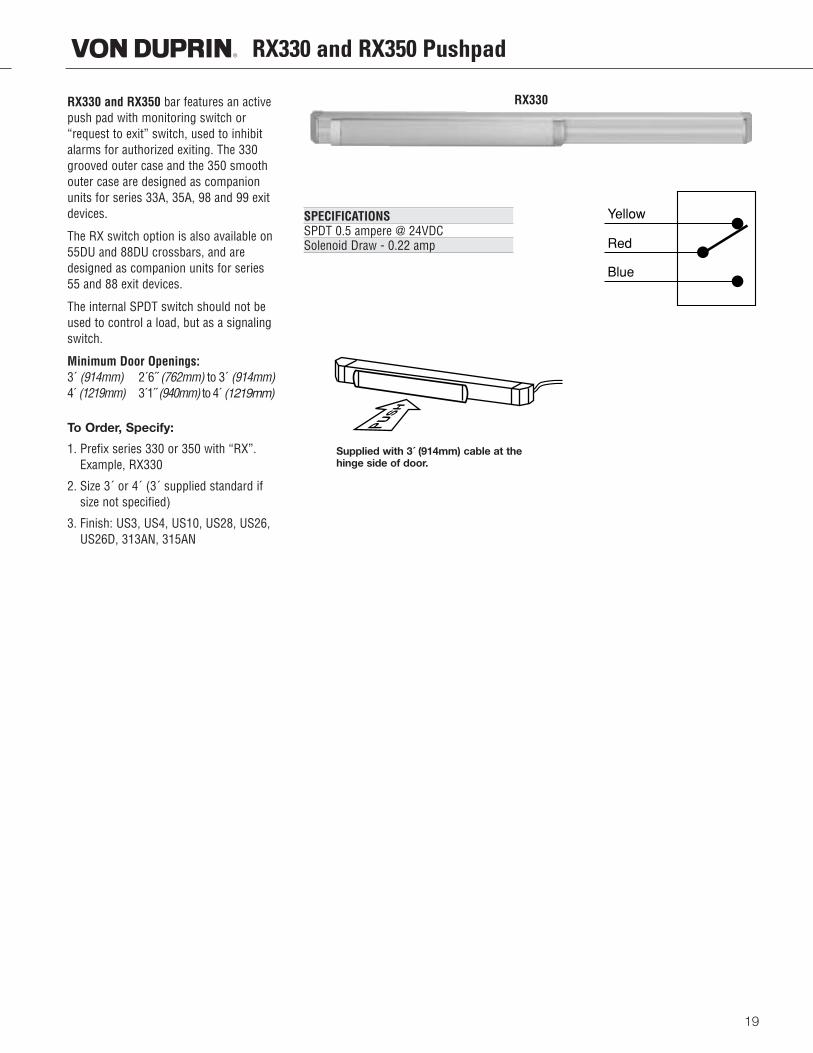
RX330 and RX350 bar features an activepush pad with monitoring switch or“request to exit” switch, used to inhibitalarms for authorized exiting. The 330grooved outer case and the 350 smoothouter case are designed as companionunits for series 33A, 35A, 98 and 99 exitdevices.
The RX switch option is also available on55DU and 88DU crossbars, and aredesigned as companion units for series55 and 88 exit devices.
The internal SPDT switch should not beused to control a load, but as a signalingswitch.
Minimum Door Openings:3 ́(914mm) 2´6 ̋(762mm) to 3 ́(914mm)4 ́(1219mm) 3´1 ̋(940mm) to 4 ́(1219mm)
To Order, Specify:
1. Prefix series 330 or 350 with “RX”.Example, RX330
2. Size 3´ or 4´ (3´ supplied standard ifsize not specified)
3. Finish: US3, US4, US10, US28, US26,US26D, 313AN, 315AN
SPECIFICATIONSSPDT 0.5 ampere @ 24VDCSolenoid Draw - 0.22 amp
Yellow
Red
Blue
RX330
Supplied with 3´ (914mm) cable at the hinge side of door.
Alarmed Exit Devices
20
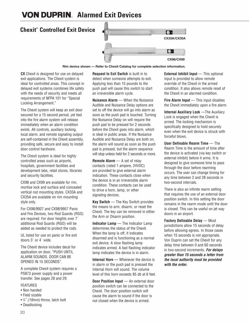
Chexit® Controlled Exit Device
CX Chexit is designed for use on delayedexit applications. The Chexit system isideal for controlled areas. This concept indelayed exit systems combines life safetywith the needs of security and meets allrequirements of NFPA 101 for “SpecialLocking Arrangement.”
The Chexit system will keep an exit doorsecured for a 15 second period, yet tiedinto the fire alarm system will releaseimmediately when an alarm conditionexists. All controls, auxiliary locking,local alarm, and remote signaling outputare self-contained in the Chexit assembly,providing safe, secure and easy to installdoor control hardware.
The Chexit system is ideal for highly controlled areas such as airports, hospitals, government facilities anddevelopment labs, retail stores, librariesand security facilities.
CX98 and CX99 are available for rim,mortise lock and surface and concealedvertical rod mounting styles. CX33A andCX35A are available on rim mountingstyle only.
For CX98/9927 and CX98/9957 Panicand Fire Devices, two Rod Guards (RGO)are required. For door heights over 7´additional Rod Guards (RGO) will beadded as needed to protect the rods.
UL listed for use on panic or fire exitdoors 3´ or 4´ wide.
The Chexit device includes decal forapplication on door, “PUSH UNTILALARM SOUNDS. DOOR CAN BEOPENED IN 15 SECONDS”.
A complete Chexit system requires aPS873 power supply and a power transfer. See pages 28 and 29.
FEATURES• Non handed• Field sizable• 3⁄4˝ (19mm) throw, latch bolt• Deadlocking
Request to Exit Switch is built in todetect when someone attempts to exit.Applying less than 15 pounds to thepush pad will cause this switch to startan irreversible alarm cycle.
Nuisance Alarm — When the NuisanceAudible and Nuisance Delay options areset to off the device will go into alarm assoon as the push pad is touched. Turningthe Nuisance Delay on will require thepush pad to be pressed for 2 secondsbefore the Chexit goes into alarm, whichis ideal in public areas. If the NuisanceAudible and Nuisance Delay are both on,the alarm will sound as soon as the pushpad is pressed, but the alarm sequencewill stop unless held for 2 seconds or more.
Remote Alarm — A set of relay contacts (rated 1 ampere, 24VDC) are provided to give external alarm indication. These contacts close whenthe device is in an irreversible alarm condition. These contacts can be used to drive a horn, lamp, or other signaling devices.
Key Switch — The Key Switch providesthe means to arm, disarm, or reset theChexit. The key can be removed in eitherthe Arm or Disarm position.
Indicator Lamp — The Indicator Lampdetermines the status of the Chexit.When the lamp is off, it indicates disarmed and is functioning as a normalexit device. A slow flashing lamp indicates armed. A fast flashing indicatorlamp indicates the device is in alarm.
Internal Horn –– Whenever the device isin alarm or the push pad is pressed theInternal Horn will sound. The volumelevel of this horn exceeds 85 db at 6 feet.
Door Position Input –– An external doorposition switch can be connected to theChexit. The door position switch willcause the alarm to sound if the door isnot closed when the device is armed.
External Inhibit Input — This optionalinput is provided to allow remote override of the Chexit in the armed condition. It also allows remote reset ofthe Chexit in an alarmed condition.
Fire Alarm Input — This input disablesthe Chexit immediately upon a fire alarm.
Internal Auxiliary Lock —The AuxiliaryLock is engaged when the Chexit isarmed. The locking mechanism is specifically designed to hold securelyeven when the exit device is struck withforceful blows.
User Definable Rearm Time –– TheRearm Time is the amount of time afterthe device is activated (via key switch orexternal inhibit) before it arms. It isdesigned to give someone time to passthrough the door before rearmingoccurs. The user can change timing forany time between 2 and 28 seconds intwo-second intervals.
There is also an infinite rearm settingthat requires the use of an external doorposition switch. In this setting the doorremains in the rearm mode until the dooris closed. This can be useful on jet waydoors in an airport.
Factory Definable Delay –– Most jurisdictions allow 15 seconds of delaybefore allowing egress. In those caseswhen 15 seconds is not appropriate, Von Duprin can set the Chexit for anydelay time between 0 and 60 seconds in two-second increments. For delaysgreater than 15 seconds a letter fromthe local authority must be providedwith the order.
Rim device shown — Refer to Chexit Catalog for complete selection information.
CX98/CX99
CX33A/CX35A
21
To Order, Specify:1. Prefix product description number “CX”.
Example: CX99L
2. Door size other than 3´ (914mm).
3. Door thickness other than 1 3/4˝ (45mm).
4. Finish.
5. Handing, LHR or RHR. Required with “CD” option.
OPTIONS(See Chexit catalog for all options and accessories)
RCM Remote Chexit Module –– is designed to provide the concept of the Chexit delayed exit system for door sizes smallerthan the standard Chexit device can accommodate. The Chexitmodule is installed in a control box and mounted in a remotelocation. Features and functions of the standard Chexit exitdevice are available on the Remote Chexit Module.
Cylinder Dogging –– Special Center Case Cylinder doggingoption is available to allow push/pull operation of the Chexit,when disarmed and used in a heavy traffic area. Prefix devicewith “CD” and specify handing.
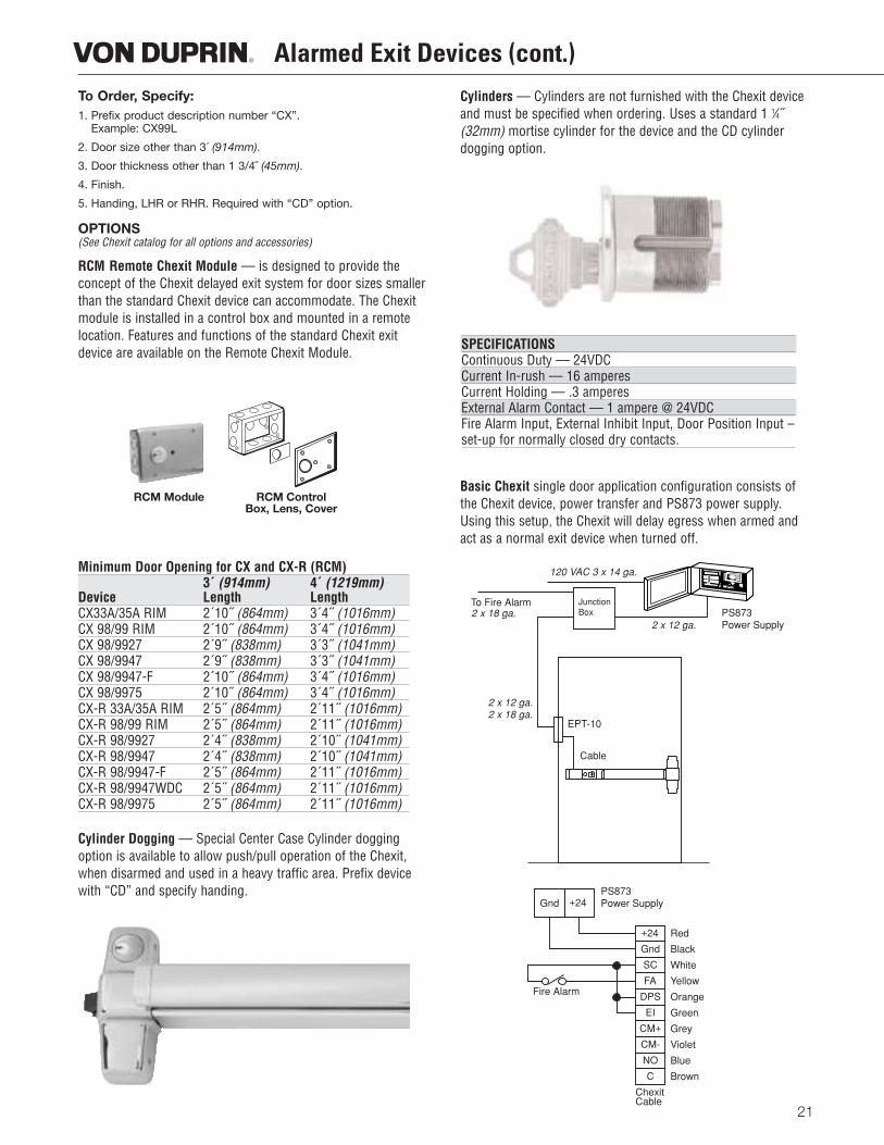
Cylinders –– Cylinders are not furnished with the Chexit deviceand must be specified when ordering. Uses a standard 1 1⁄4˝(32mm) mortise cylinder for the device and the CD cylinder dogging option.
Basic Chexit single door application configuration consists ofthe Chexit device, power transfer and PS873 power supply.Using this setup, the Chexit will delay egress when armed andact as a normal exit device when turned off.
Alarmed Exit Devices (cont.)
Minimum Door Opening for CX and CX-R (RCM)3´ (914mm) 4´ (1219mm)
Device Length LengthCX33A/35A RIM 2´10˝ (864mm) 3´4˝ (1016mm)CX 98/99 RIM 2´10˝ (864mm) 3´4˝ (1016mm)CX 98/9927 2´9˝ (838mm) 3´3˝ (1041mm)CX 98/9947 2´9˝ (838mm) 3´3˝ (1041mm)CX 98/9947-F 2´10˝ (864mm) 3´4˝ (1016mm)CX 98/9975 2´10˝ (864mm) 3´4˝ (1016mm)CX-R 33A/35A RIM 2´5˝ (864mm) 2´11˝ (1016mm)CX-R 98/99 RIM 2´5˝ (864mm) 2´11˝ (1016mm)CX-R 98/9927 2´4˝ (838mm) 2´10˝ (1041mm)CX-R 98/9947 2´4˝ (838mm) 2´10˝ (1041mm)CX-R 98/9947-F 2´5˝ (864mm) 2´11˝ (1016mm)CX-R 98/9947WDC 2´5˝ (864mm) 2´11˝ (1016mm)CX-R 98/9975 2´5˝ (864mm) 2´11˝ (1016mm)
SPECIFICATIONSContinuous Duty –– 24VDCCurrent In-rush –– 16 amperesCurrent Holding –– .3 amperesExternal Alarm Contact –– 1 ampere @ 24VDC Fire Alarm Input, External Inhibit Input, Door Position Input –set-up for normally closed dry contacts.
120 VAC 3 x 14 ga.
Fire Alarm
To Fire Alarm
2 x 12 ga.
2 x 12 ga.2 x 18 ga.
2 x 18 ga.
Red
JunctionBox PS873
Power Supply
EPT-10
Cable
PS873Power Supply
Black
White
Yellow
Orange
Green
Grey
Violet
Blue
+24
Gnd
+24Gnd
SC
FA
DPS
EI
CM+
CM-
NO
C Brown
ChexitCable
RCM Module RCM ControlBox, Lens, Cover
22
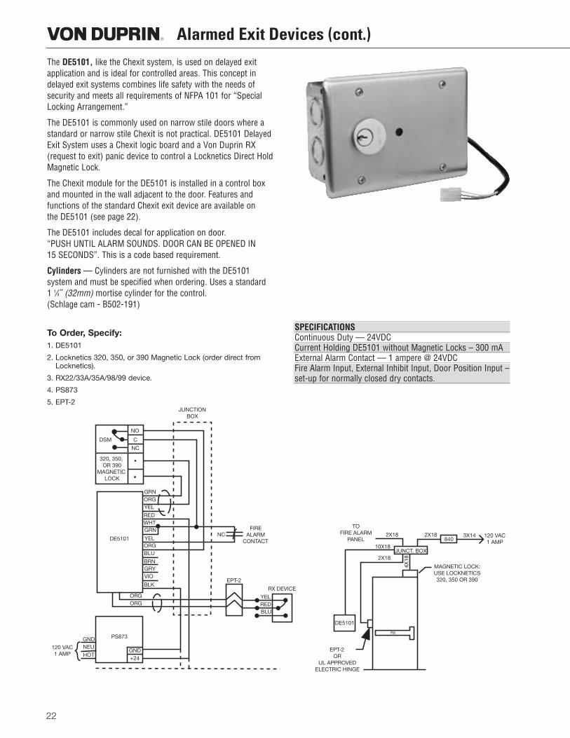
Alarmed Exit Devices (cont.)The DE5101, like the Chexit system, is used on delayed exitapplication and is ideal for controlled areas. This concept indelayed exit systems combines life safety with the needs ofsecurity and meets all requirements of NFPA 101 for “SpecialLocking Arrangement.”
The DE5101 is commonly used on narrow stile doors where astandard or narrow stile Chexit is not practical. DE5101 DelayedExit System uses a Chexit logic board and a Von Duprin RX(request to exit) panic device to control a Locknetics Direct HoldMagnetic Lock.
The Chexit module for the DE5101 is installed in a control boxand mounted in the wall adjacent to the door. Features and functions of the standard Chexit exit device are available on the DE5101 (see page 22).
The DE5101 includes decal for application on door. “PUSH UNTIL ALARM SOUNDS. DOOR CAN BE OPENED IN15 SECONDS”. This is a code based requirement.
Cylinders –– Cylinders are not furnished with the DE5101 system and must be specified when ordering. Uses a standard 1 1⁄4˝ (32mm) mortise cylinder for the control. (Schlage cam - B502-191)
To Order, Specify:1. DE5101
2. Locknetics 320, 350, or 390 Magnetic Lock (order direct fromLocknetics).
3. RX22/33A/35A/98/99 device.
4. PS873
5. EPT-2
SPECIFICATIONSContinuous Duty –– 24VDCCurrent Holding DE5101 without Magnetic Locks – 300 mAExternal Alarm Contact –– 1 ampere @ 24VDC Fire Alarm Input, External Inhibit Input, Door Position Input –set-up for normally closed dry contacts.
DSM
NO
C
NC
320, 350, OR 390
MAGNETIC LOCK
GRNORGYEL
REDWHTGRN
YELORGBLU
BRNGRYVIO
BLK
ORGORG
GND+24
GNDNEU
HOT120 VAC1 AMP
EPT-2
FIREALARM
CONTACTNC
RX DEVICE
YELREDBLU
DE5101
JUNCTIONBOX
PS873
TOFIRE ALARM
PANEL2X18
10X18
2X18JUNCT. BOX
2X18840
3X14 120 VAC1 AMP
MAGNETIC LOCK:USE LOCKNETICS320, 350 OR 390
RX
DE5101
EPT-2OR
UL APPROVEDELECTRIC HINGE
4X18
23
Alarmed Exit Devices
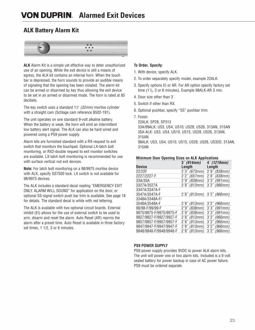
ALK Alarm Kit is a simple yet effective way to deter unauthorizeduse of an opening. While the exit device is still a means ofegress, the ALK kit contains an internal horn. When the touchbar is depressed, the horn sounds to provide an audible meansof signaling that the opening has been violated. The alarm kitcan be armed or disarmed by key thus allowing the exit deviceto be set in an armed or disarmed mode. The horn is rated at 85decibels.
The key switch uses a standard 11⁄4" (32mm) mortise cylinderwith a straight cam (Schlage cam reference B502-191).
The unit operates on one standard 9-volt alkaline battery. When the battery is weak, the horn will emit an intermittent low battery alert signal. The ALK can also be hard wired andpowered using a PS9 power supply.
Alarm kits are furnished standard with a RX-request to exitswitch that monitors the touchpad. Optional LX-latch bolt monitoring, or RX2-double request to exit monitor switches are available. LX-latch bolt monitoring is recommended for usewith surface vertical rod exit devices.
Note: For latch bolt monitoring on a 98/9975 mortise devicewith ALK, specify SS7500 lock. LX switch is not available for98/9975 devices.
The ALK includes a standard decal reading “EMERGENCY EXITONLY. ALARM WILL SOUND” for application on the door, oroptional SS-signal switch push bar trim is available. See page 18for details. The standard decal is white with red lettering.
The ALK is available with two optional circuit boards. Externalinhibit (EI) allows for the use of external switch to be used toarm, disarm and reset the alarm. Auto Reset (AR) rearms thealarm after a preset time. Auto Reset is available in three factoryset times, 1 1/2, 3 or 6 minutes.
To Order, Specify:
1. With device, specify ALK.
2. To order separately specify model, example 22ALK.
3. Specify options EI or AR. For AR option specify factory settime (11/2, 3 or 6 minutes). Example 98ALK-AR 3 min.
4. Door size other than 3´.
5. Switch if other than RX.
6. Optional pushbar, specify “SS” pushbar trim.
7. Finish:22ALK: SP28, SP31333A/99ALK: US3, US4, US10, US28, US26, 313AN, 315AN35A-ALK: US3, US4, US10, US15, US28, US26, 313AN,315AN98ALK: US3, US4, US10, US15, US28, US26, US32D, 313AN,315AN
PS9 POWER SUPPLYPS9 power supply provides 9VDC to power ALK alarm kits. The unit will power one or two alarm kits. Included is a 9 voltsealed battery for power backup in case of AC power failure.PS9 must be ordered separate.
ALK Battery Alarm Kit
Minimum Door Opening Sizes on ALK Applications3´ (914mm) 4´ (1219mm)
Device Length Length22/22F 2´3˝ (673mm) 2´9˝ (838mm)2227/2227-F 2´2˝ (657mm) 2´8˝ (838mm)33A/35A 2´9˝ (838mm) 3´3˝ (991mm)3327A/3527A 2´8˝ (813mm) 3´2˝ (966mm)3347A/3347A-F3547A/3547A-F 2´8˝ (813mm) 3´2˝ (966mm)3348A/3348A-F/3548A/3548A-F 2´8˝ (813mm) 3´2˝ (966mm)98/98-F/99/99-F 2´9˝ (838mm) 3´3˝ (991mm)9875/9875-F/9975/9975-F 2´9˝ (838mm) 3´3˝ (991mm)9827/9827-F/9927/9927-F 2´8˝ (813mm) 3´2˝ (966mm)9857/9857-F/9957/9957-F 2´8˝ (813mm) 3´2˝ (966mm)9847/9847-F/9947/9947-F 2´8˝ (813mm) 3´2˝ (966mm)9848/9848-F/9948/9948-F 2´8˝ (813mm) 3´2˝ (966mm)
24
GUARD-X Exit Device
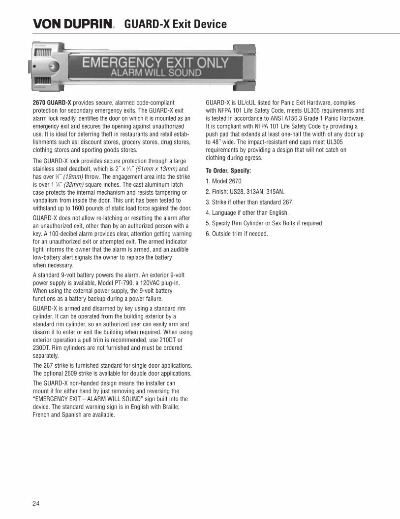
2670 GUARD-X provides secure, alarmed code-compliant protection for secondary emergency exits. The GUARD-X exitalarm lock readily identifies the door on which it is mounted as anemergency exit and secures the opening against unauthorizeduse. It is ideal for deterring theft in restaurants and retail estab-lishments such as: discount stores, grocery stores, drug stores,clothing stores and sporting goods stores.
The GUARD-X lock provides secure protection through a large stainless steel deadbolt, which is 2˝ x 1⁄ 2˝ (51mm x 13mm) andhas over 3⁄4˝ (19mm) throw. The engagement area into the strikeis over 1 1⁄4˝ (32mm) square inches. The cast aluminum latchcase protects the internal mechanism and resists tampering orvandalism from inside the door. This unit has been tested towithstand up to 1600 pounds of static load force against the door.
GUARD-X does not allow re-latching or resetting the alarm afteran unauthorized exit, other than by an authorized person with akey. A 100-decibel alarm provides clear, attention getting warningfor an unauthorized exit or attempted exit. The armed indicatorlight informs the owner that the alarm is armed, and an audiblelow-battery alert signals the owner to replace the battery when necessary.
A standard 9-volt battery powers the alarm. An exterior 9-voltpower supply is available, Model PT-790, a 120VAC plug-in.When using the external power supply, the 9-volt battery functions as a battery backup during a power failure.
GUARD-X is armed and disarmed by key using a standard rimcylinder. It can be operated from the building exterior by a standard rim cylinder, so an authorized user can easily arm anddisarm it to enter or exit the building when required. When usingexterior operation a pull trim is recommended, use 210DT or230DT. Rim cylinders are not furnished and must be orderedseparately.
The 267 strike is furnished standard for single door applications.The optional 2609 strike is available for double door applications.
The GUARD-X non-handed design means the installer canmount it for either hand by just removing and reversing the“EMERGENCY EXIT – ALARM WILL SOUND” sign built into thedevice. The standard warning sign is in English with Braille;French and Spanish are available.
GUARD-X is UL/cUL listed for Panic Exit Hardware, complieswith NFPA 101 Life Safety Code, meets UL305 requirements andis tested in accordance to ANSI A156.3 Grade 1 Panic Hardware.It is compliant with NFPA 101 Life Safety Code by providing apush pad that extends at least one-half the width of any door upto 48˝ wide. The impact-resistant end caps meet UL305 requirements by providing a design that will not catch on clothing during egress.
To Order, Specify:
1. Model 2670
2. Finish: US28, 313AN, 315AN.
3. Strike if other than standard 267.
4. Language if other than English.
5. Specify Rim Cylinder or Sex Bolts if required.
6. Outside trim if needed.
25
Electric Mortise Lock E7500
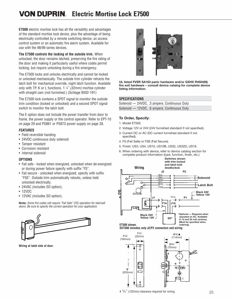
E7500 electric mortise lock has all the versatility and advantagesof the standard mortise lock device, plus the advantage of beingelectrically controlled by a remote switching device, an accesscontrol system or an automatic fire alarm system. Available foruse with the 98/99 series devices.
The E7500 controls the locking of the outside trim. Whenunlocked, the door remains latched, preserving the fire rating ofthe door and making it particularly useful where codes permitlocking, but require unlocking during a fire emergency.
The E7500 locks and unlocks electrically and cannot be lockedor unlocked mechanically. The outside trim cylinder retracts thelatch bolt for mechanical override, night latch function. Availableonly with TP, K or L functions. 1 1⁄4˝ (32mm) mortise cylinderwith straight cam (not furnished.) (Schlage B502-191)
The E7500 lock contains a SPDT signal to monitor the outsidetrim condition (locked or unlocked) and a second SPDT signalswitch to monitor the latch bolt.
The E option does not include the power transfer from door toframe, the power supply or the control operator. Refer to EPT-10on page 29 and PS861 or PS873 power supply on page 28.
FEATURES• Field reversible handing• 24VDC continuous duty solenoid• Tamper resistant• Corrosion resistant• Internal solenoid
OPTIONS• Fail safe - locked when energized, unlocked when de-energized
or during power failure specify with suffix “FS”.• Fail secure - unlocked when energized, specify with suffix
“FSE”. Outside trim automatically relocks, unless heldunlocked electrically.
• 24VAC (includes SO option).• 12VDC• 12VAC (includes SO option).
Note: Some fire codes will require “Fail Safe” (FS) operation for stairwelldoors. Be sure to specify the correct operation for your application.
UL listed FVSR SA163 panic hardware and/or GXHX R4504(N)fire exit hardware – consult device catalog for complete devicelisting information.
SPECIFICATIONSSolenoid — 24VDC, .3 ampere, Continuous DutySolenoid — 12VDC, .6 ampere, Continuous Duty
To Order, Specify:1. Model E7500.
2. Voltage 12V or 24V (24V furnished standard if not specified).
3. Current DC or AC (DC current furnished standard if not specified).
4. FS (Fail Safe) or FSE (Fail Secure).
5. Finish: US3, US4, US10, US10B, US32, US32D, US19.
6. When ordering with device, refer to device catalog section forcomplete product information (type, function, finish, etc.)
ET500 shown.SS7500 includes only J2/P2 connectors and wiring
Wiring at latch side of door.
4 13⁄16˝ (122mm) clearance required for wiring.
J2 P2
P1J1
P1A
SO*Black 24VYellow 12V
Black 24VYellow 12V
J1A
BlueRed
YellowGrayWhite
Violet
*Optional — Required whenoperated on AC. Availablein 12 and 24 volt versions.(Must be specified whenordering)
White
Wiring
Switches shownwith trim lockedand latch boltdeadlocked.
Solenoid
Latch Bolt
71/4˝(184mm)
11/4˝(32mm)
41/2˝▲(114mm)
23/4˝(70mm)
8 ˝(203mm)
26
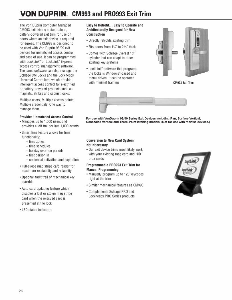
CM993 and PRO993 Exit TrimThe Von Duprin Computer ManagedCM993 exit trim is a stand-alone, battery-powered exit trim for use ondoors where an exit device is requiredfor egress. The CM993 is designed to be used with Von Duprin 98/99 exitdevices for unmatched access controland ease of use. It can be programmedwith LockLink™ or LockLink™ Expressaccess control management software.The same software can also manage theSchlage CM Locks and the LockneticsUniversal Controllers, which provideintelligent access control for electrified or battery-powered products such asmagnets, strikes and cabinet locks.
Multiple users, Multiple access points.Multiple credentials. One way to manage them.
Provides Unmatched Access Control• Manages up to 1,000 users and
provides audit trail for last 1,000 events
• SmartTime feature allows for time functionality:
– time zones– time schedules– holiday override periods– first person in– credential activation and expiration
• Full-swipe mag stripe card reader formaximum readability and reliability
• Optional audit trail of mechanical keyoverride
• Auto card updating feature whichdisables a lost or stolen mag stripecard when the reissued card is presented at the lock
• LED status indicators
Easy to Retrofit... Easy to Operate andArchitecturally Designed for NewConstruction
• Directly retrofits existing trim
• Fits doors from 13⁄8˝ to 2 1⁄4˝ thick
• Comes with Schlage Everest 1 1⁄4˝ cylinder, but can adapt to other existing key systems
• LockLink™ software that programs the locks is Windows®-based andmenu-driven. It can be operated with minimal training
Conversion to New Card System Not Necessary• Our exit device trims most likely work
with your existing mag card and HIDprox cards
Programmable PRO993 Exit Trim forManual Programming• Manually program up to 120 keycodes
right at the trim
• Similar mechanical features as CM993
• Complements Schlage PRO andLocknetics PRO Series products
For use with VonDuprin 98/99 Series Exit Devices including Rim, Surface Vertical,Concealed Vertical and Three-Point latching models. (Not for use with mortise devices.)
CM993 Exit Trim
How To Order Exit Trim
27
PRO993 Manuallyprogrammed exit trim
CM993 Computermanaged exit trim
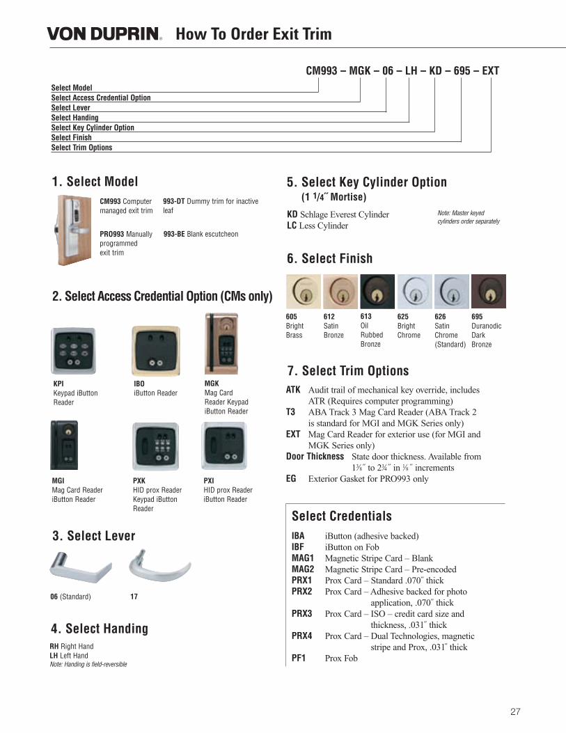
1. Select Model
2. Select Access Credential Option (CMs only)
06 (Standard) 17
KPI Keypad iButton Reader
IBOiButton Reader
MGK Mag Card Reader KeypadiButton Reader
MGI Mag Card ReaderiButton Reader
PXK HID prox ReaderKeypad iButtonReader
PXI HID prox ReaderiButton Reader
3. Select Lever
4. Select Handing
5. Select Key Cylinder Option(1 1/4˝ Mortise)
RH Right HandLH Left HandNote: Handing is field-reversible
KD Schlage Everest Cylinder LC Less Cylinder
6. Select Finish
605BrightBrass
612Satin Bronze
613Oil Rubbed Bronze
625 Bright Chrome
626 SatinChrome(Standard)
695DuranodicDarkBronze
IBA iButton (adhesive backed)IBF iButton on FobMAG1 Magnetic Stripe Card – BlankMAG2 Magnetic Stripe Card – Pre-encodedPRX1 Prox Card – Standard .070˝ thickPRX2 Prox Card – Adhesive backed for photo
application, .070˝ thickPRX3 Prox Card – ISO – credit card size and
thickness, .031˝ thickPRX4 Prox Card – Dual Technologies, magnetic
stripe and Prox, .031̋ thickPF1 Prox Fob
Select Credentials
ATK Audit trail of mechanical key override, includes ATR (Requires computer programming)
T3 ABA Track 3 Mag Card Reader (ABA Track 2 is standard for MGI and MGK Series only)
EXT Mag Card Reader for exterior use (for MGI and MGK Series only)
Door Thickness State door thickness. Available from 13⁄8˝ to 23⁄4 ˝ in 1⁄8 ˝ increments
EG Exterior Gasket for PRO993 only
7. Select Trim Options
CM993 – MGK – 06 – LH – KD – 695 – EXTSelect ModelSelect Access Credential OptionSelect LeverSelect HandingSelect Key Cylinder OptionSelect FinishSelect Trim Options
Note: Master keyed cylinders order separately
993-DT Dummy trim for inactiveleaf
993-BE Blank escutcheon
28
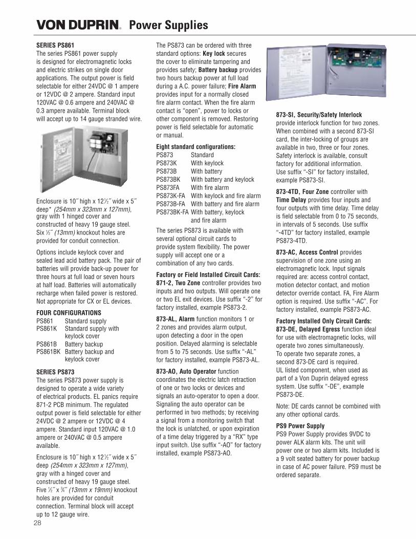
Power SuppliesSERIES PS861The series PS861 power supplyis designed for electromagnetic locksand electric strikes on single door applications. The output power is fieldselectable for either 24VDC @ 1 ampereor 12VDC @ 2 ampere. Standard input120VAC @ 0.6 ampere and 240VAC @0.3 ampere available. Terminal block will accept up to 14 gauge stranded wire.
Enclosure is 10˝ high x 121⁄2˝ wide x 5˝deep* (254mm x 323mm x 127mm), gray with 1 hinged cover and constructed of heavy 19 gauge steel. Six 1⁄2˝ (13mm) knockout holes are provided for conduit connection.
Options include keylock cover and sealed lead acid battery pack. The pair ofbatteries will provide back-up power forthree hours at full load or seven hours at half load. Batteries will automaticallyrecharge when failed power is restored.Not appropriate for CX or EL devices.
FOUR CONFIGURATIONSPS861 Standard supplyPS861K Standard supply with
keylock coverPS861B Battery backupPS861BK Battery backup and
keylock cover
SERIES PS873The series PS873 power supply isdesigned to operate a wide variety of electrical products. EL panics require871-2 PCB minimum. The regulatedoutput power is field selectable for either24VDC @ 2 ampere or 12VDC @ 4ampere. Standard input 120VAC @ 1.0ampere or 240VAC @ 0.5 ampereavailable.
Enclosure is 10˝ high x 12 1⁄2˝ wide x 5˝deep (254mm x 323mm x 127mm), gray with a hinged cover and constructed of heavy 19 gauge steel. Five 1⁄2˝ x 3⁄4˝ (13mm x 19mm) knockoutholes are provided for conduit connection. Terminal block will accept up to 12 gauge wire.
The PS873 can be ordered with threestandard options: Key lock secures the cover to eliminate tampering andprovides safety; Battery backup providestwo hours backup power at full load during a A.C. power failure; Fire Alarmprovides input for a normally closed fire alarm contact. When the fire alarm contact is “open”, power to locks orother component is removed. Restoringpower is field selectable for automatic or manual.
Eight standard configurations:PS873 StandardPS873K With keylockPS873B With batteryPS873BK With battery and keylockPS873FA With fire alarmPS873K-FA With keylock and fire alarmPS873B-FA With battery and fire alarmPS873BK-FA With battery, keylock
and fire alarm
The series PS873 is available with several optional circuit cards to provide system flexibility. The powersupply will accept one or a combination of any two cards.
Factory or Field Installed Circuit Cards:871-2, Two Zone controller provides twoinputs and two outputs. Will operate oneor two EL exit devices. Use suffix “-2” forfactory installed, example PS873-2.
873-AL, Alarm function monitors 1 or 2 zones and provides alarm output, upon detecting a door in the open position. Delayed alarming is selectablefrom 5 to 75 seconds. Use suffix “-AL”for factory installed, example PS873-AL.
873-AO, Auto Operator function coordinates the electric latch retractionof one or two locks or devices and signals an auto-operator to open a door.Signaling the auto operator can be performed in two methods; by receivinga signal from a monitoring switch thatthe lock is unlatched, or upon expirationof a time delay triggered by a “RX” typeinput switch. Use suffix “-AO” for factoryinstalled, example PS873-AO.
873-SI, Security/Safety Interlockprovide interlock function for two zones.When combined with a second 873-SIcard, the inter-locking of groups areavailable in two, three or four zones.Safety interlock is available, consult factory for additional information. Use suffix “-SI” for factory installed,example PS873-SI.
873-4TD, Four Zone controller with Time Delay provides four inputs andfour outputs with time delay. Time delayis field selectable from 0 to 75 seconds, in intervals of 5 seconds. Use suffix “-4TD” for factory installed, examplePS873-4TD.
873-AC, Access Control provides supervision of one zone using an electromagnetic lock. Input signalsrequired are: access control contact,motion detector contact, and motiondetector override contact. FA, Fire Alarmoption is required. Use suffix “-AC”. Forfactory installed, example PS873-AC.
Factory Installed Only Circuit Cards:873-DE, Delayed Egress function idealfor use with electromagnetic locks, willoperate two zones simultaneously. To operate two separate zones, a second 873-DE card is required. UL listed component, when used as part of a Von Duprin delayed egress system. Use suffix “-DE”, examplePS873-DE.
Note: DE cards cannot be combined withany other optional cards.
PS9 Power SupplyPS9 Power Supply provides 9VDC topower ALK alarm kits. The unit willpower one or two alarm kits. Included isa 9 volt seated battery for power backupin case of AC power failure. PS9 must beordered separate.
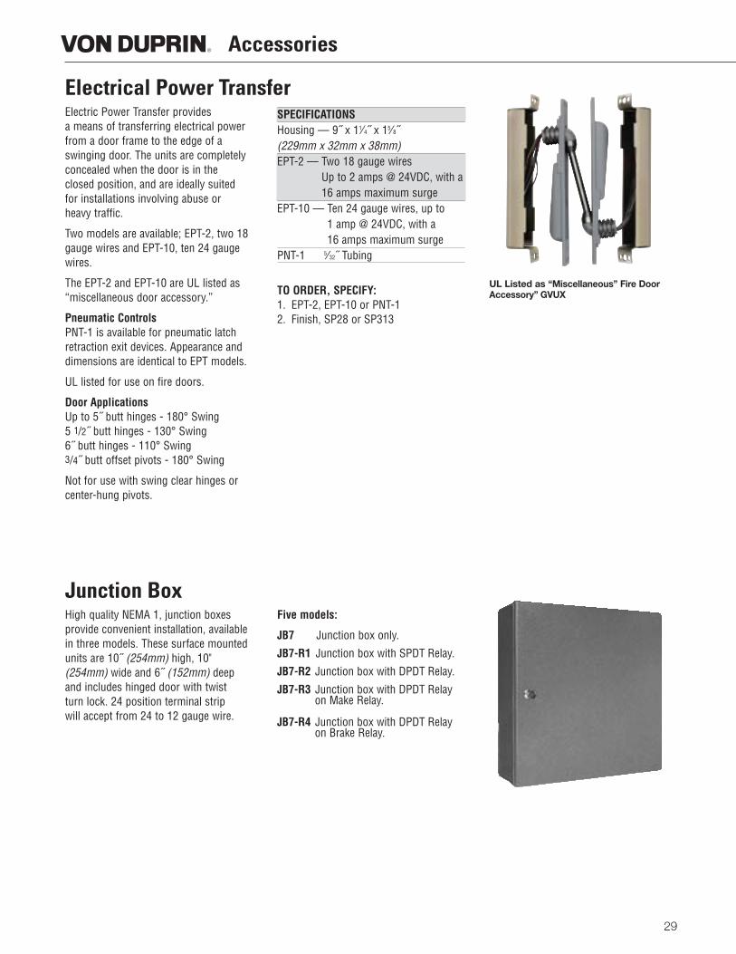
Electric Power Transfer provides a means of transferring electrical powerfrom a door frame to the edge of aswinging door. The units are completelyconcealed when the door is in the closed position, and are ideally suited for installations involving abuse or heavy traffic.
Two models are available; EPT-2, two 18gauge wires and EPT-10, ten 24 gaugewires.
The EPT-2 and EPT-10 are UL listed as“miscellaneous door accessory.”
Pneumatic ControlsPNT-1 is available for pneumatic latchretraction exit devices. Appearance anddimensions are identical to EPT models.
UL listed for use on fire doors.
Door ApplicationsUp to 5˝ butt hinges - 180° Swing5 1/2˝ butt hinges - 130° Swing6˝ butt hinges - 110° Swing3/4˝ butt offset pivots - 180° Swing
Not for use with swing clear hinges orcenter-hung pivots.
SPECIFICATIONSHousing — 9˝ x 11⁄4˝ x 15⁄8˝(229mm x 32mm x 38mm)EPT-2 — Two 18 gauge wires
Up to 2 amps @ 24VDC, with a16 amps maximum surge
EPT-10 — Ten 24 gauge wires, up to 1 amp @ 24VDC, with a 16 amps maximum surge
PNT-1 5⁄32˝ Tubing
TO ORDER, SPECIFY:1. EPT-2, EPT-10 or PNT-12. Finish, SP28 or SP313
UL Listed as “Miscellaneous” Fire DoorAccessory” GVUX
Electrical Power Transfer
High quality NEMA 1, junction boxesprovide convenient installation, availablein three models. These surface mountedunits are 10˝ (254mm) high, 10"(254mm) wide and 6˝ (152mm) deepand includes hinged door with twist turn lock. 24 position terminal strip will accept from 24 to 12 gauge wire.
Five models:
JB7 Junction box only.
JB7-R1 Junction box with SPDT Relay.
JB7-R2 Junction box with DPDT Relay.
JB7-R3 Junction box with DPDT Relayon Make Relay.
JB7-R4 Junction box with DPDT Relayon Brake Relay.
Junction Box
29
Accessories
30
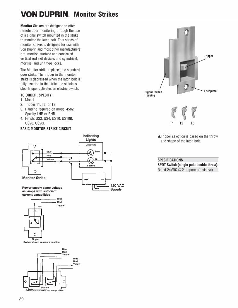
Monitor StrikesMonitor Strikes are designed to offerremote door monitoring through the useof a signal switch mounted in the striketo monitor the latch bolt. This series ofmonitor strikes is designed for use withVon Duprin and most other manufacturers’rim, mortise, surface and concealed vertical rod exit devices and cylindrical,mortise, and unit type locks.
The Monitor strike replaces the standarddoor strike. The tripper in the monitorstrike is depressed when the latch bolt isfully inserted in the strike the stainlesssteel tripper activates an electric switch.
TO ORDER, SPECIFY:1. Model2. Tripper T1, T2, or T3.3. Handing required on model 4582.
Specify LHR or RHR.4. Finish: US3, US4, US10, US10B,
US26, US26D. T1 T2 T3
▲Tripper selection is based on the throwand shape of the latch bolt.
SPECIFICATIONSSPDT Switch (single pole double throw):Rated 24VDC @ 2 amperes (resistive)
BASIC MONITOR STRIKE CIRCUIT
Power supply same voltageas lamps with sufficientcurrent capabilities
Tripper
FaceplateSignal SwitchHousing
Blue
Red
Yellow
BlueRed
Yellow
Blue
Grn
Monitor Strike
IndicatingLights
120 VACSupply
Unsecure
Secure
Single
DoubleSwitches shown in secure position
Switch shown in secure position
BlueRedYellow
BlueRedYellow
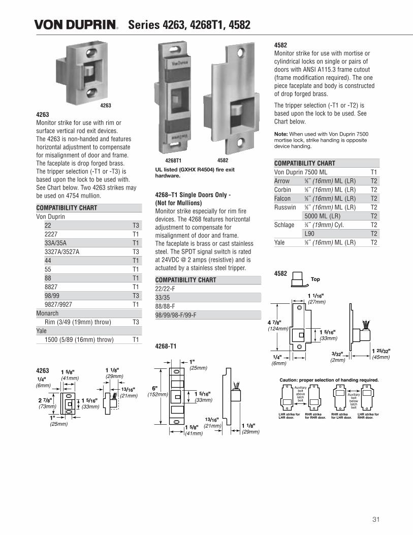
4263Monitor strike for use with rim or surface vertical rod exit devices. The 4263 is non-handed and featureshorizontal adjustment to compensate for misalignment of door and frame. The faceplate is drop forged brass. The tripper selection (-T1 or -T3) isbased upon the lock to be used with. See Chart below. Two 4263 strikes maybe used on 4754 mullion.
COMPATIBILITY CHARTVon Duprin
22 T32227 T133A/35A T13327A/3527A T344 T155 T188 T18827 T198/99 T39827/9927 T1
MonarchRim (3/49 (19mm) throw) T3
Yale1500 (5/89 (16mm) throw) T1
4263
UL listed (GXHX R4504) fire exit hardware.
4268–T1 Single Doors Only - (Not for Mullions)Monitor strike especially for rim firedevices. The 4268 features horizontaladjustment to compensate for misalignment of door and frame. The faceplate is brass or cast stainlesssteel. The SPDT signal switch is rated at 24VDC @ 2 amps (resistive) and isactuated by a stainless steel tripper.
COMPATIBILITY CHART22/22-F33/3588/88-F98/99/98-F/99-F
4268-T1
4582Monitor strike for use with mortise orcylindrical locks on single or pairs ofdoors with ANSI A115.3 frame cutout(frame modification required). The onepiece faceplate and body is constructedof drop forged brass.
The tripper selection (-T1 or -T2) isbased upon the lock to be used. SeeChart below.
Note: When used with Von Duprin 7500mortise lock, strike handing is oppositedevice handing.
COMPATIBILITY CHARTVon Duprin 7500 ML T1Arrow 5⁄8˝ (16mm) ML (LR) T2Corbin 5⁄8˝ (16mm) ML (LR) T2Falcon 5⁄8˝ (16mm) ML (LR) T2Russwin 5⁄8˝ (16mm) ML (LR) T2
5000 ML (LR) T2Schlage 3⁄4˝ (19mm) Cyl. T2
L90 T2Yale 5⁄8˝ (16mm) ML (LR) T2
4582
1 5/16"�(33mm)
1 5/8"�(41mm)
1 1/8"�(29mm)
2 7/8"�(73mm)
13/16"�(21mm)
1/4"�(6mm)
1"�(25mm)
1 5/16"�(33mm)
1 5/8"�(41mm)
1 1/8"�(29mm)
13/16"�(21mm)
1"�(25mm)
6"�(152mm)
Caution: proper selection of handing required.
LHR strike for LHR door.
RHR strike for RHR door.
RHR strike for LHR door.
LHR strike for RHR door.
Auxiliary bolt
above latch bolt
Auxiliary bolt
below latch bolt
1 1/16"�(27mm)
1 5/16"�(33mm)
1 25/32"�(45mm)
4 7/8"�(124mm)
1/4"�(6mm)
3/32"�(2mm)
Top
4263
4268T1 4582
Series 4263, 4268T1, 4582
31
32
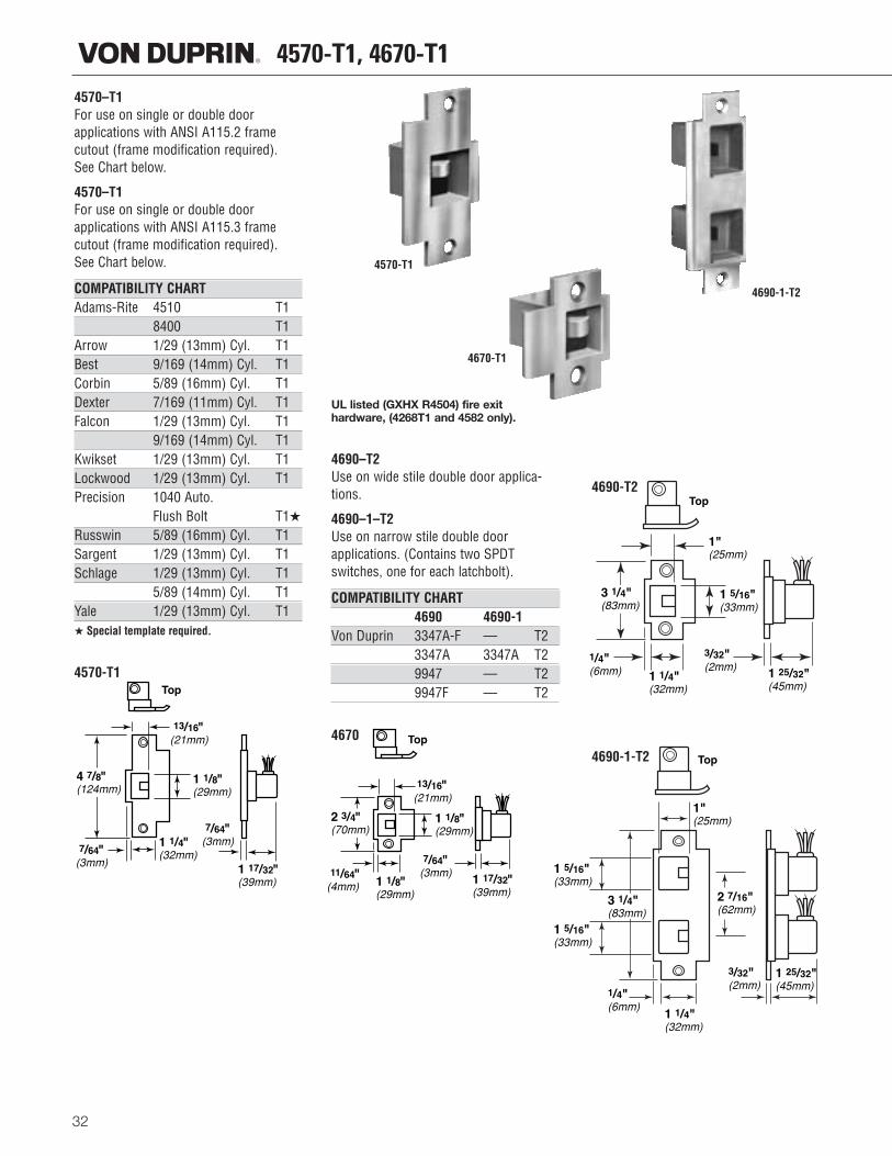
4570-T1, 4670-T14570–T1 For use on single or double door applications with ANSI A115.2 framecutout (frame modification required). See Chart below.
4570–T1For use on single or double door applications with ANSI A115.3 framecutout (frame modification required). See Chart below.
COMPATIBILITY CHARTAdams-Rite 4510 T1
8400 T1Arrow 1/29 (13mm) Cyl. T1Best 9/169 (14mm) Cyl. T1Corbin 5/89 (16mm) Cyl. T1Dexter 7/169 (11mm) Cyl. T1Falcon 1/29 (13mm) Cyl. T1
9/169 (14mm) Cyl. T1Kwikset 1/29 (13mm) Cyl. T1Lockwood 1/29 (13mm) Cyl. T1Precision 1040 Auto.
Flush Bolt T1★
Russwin 5/89 (16mm) Cyl. T1Sargent 1/29 (13mm) Cyl. T1Schlage 1/29 (13mm) Cyl. T1
5/89 (14mm) Cyl. T1Yale 1/29 (13mm) Cyl. T1★ Special template required.
4570-T1
UL listed (GXHX R4504) fire exit hardware, (4268T1 and 4582 only).
4690–T2Use on wide stile double door applica-tions.
4690–1–T2Use on narrow stile double door applications. (Contains two SPDT switches, one for each latchbolt).
COMPATIBILITY CHART4690 4690-1
Von Duprin 3347A-F — T23347A 3347A T29947 — T29947F — T2
4670
4570-T1
4670-T1
4690-1-T2
1"(25mm)
1 25/32"(45mm)
1 1/4"(32mm)
1/4"(6mm)
3/32"(2mm)
1 5/16"(33mm)
3 1/4"(83mm)
Top
1"(25mm)
1 5/16"(33mm)
1 5/16"(33mm)
2 7/16"(62mm)
1 1/4"(32mm)
1/4"(6mm)
1 25/32"(45mm)
3/32"(2mm)
3 1/4"(83mm)
Top
2 3/4"�(70mm)
1 1/8"�(29mm)
1 17/32"�(39mm)
13/16"�(21mm)
11/64"�(4mm)
7/64"�(3mm)
Top
1 1/8"�(29mm)
4 7/8"�(124mm)
1 1/8"�(29mm)
1 1/4"�(32mm)
1 17/32"�(39mm)
13/16"�(21mm)
7/64"�(3mm)
7/64"�(3mm)
Top
4690-T2
4690-1-T2
1" (25mm) DiameterClearance
Reinforcement
Filler block is tobe supplied by theframe mgf. forconditions similarto this.
Reinforcement
QUICK DISCONNECT
SOFFIT DETAILS
RedYellowBlueBlackBlack
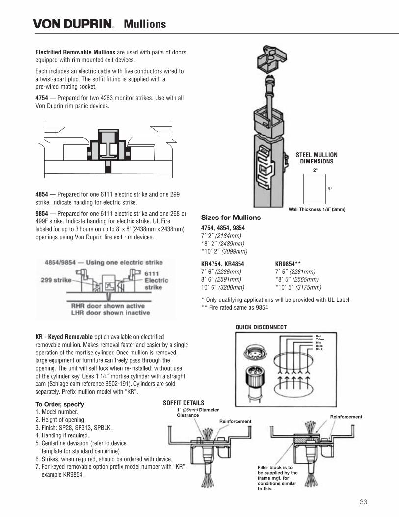
Electrified Removable Mullions are used with pairs of doorsequipped with rim mounted exit devices.
Each includes an electric cable with five conductors wired toa twist-apart plug. The soffit fitting is supplied with a pre-wired mating socket.
4754 — Prepared for two 4263 monitor strikes. Use with allVon Duprin rim panic devices.
4854 — Prepared for one 6111 electric strike and one 299strike. Indicate handing for electric strike.
9854 — Prepared for one 6111 electric strike and one 268 or499F strike. Indicate handing for electric strike. UL Firelabeled for up to 3 hours on up to 8' x 8' (2438mm x 2438mm)openings using Von Duprin fire exit rim devices.
KR - Keyed Removable option available on electrified removable mullion. Makes removal faster and easier by a singleoperation of the mortise cylinder. Once mullion is removed,large equipment or furniture can freely pass through the opening. The unit will self lock when re-installed, without useof the cylinder key. Uses 1 1/4˝ mortise cylinder with a straightcam (Schlage cam reference B502-191). Cylinders are sold separately. Prefix mullion model with “KR”.
To Order, specify1. Model number.2. Height of opening3. Finish: SP28, SP313, SPBLK.4. Handing if required.5. Centerline deviation (refer to device
template for standard centerline).6. Strikes, when required, should be ordered with device.7. For keyed removable option prefix model number with “KR”,
example KR9854.
Sizes for Mullions4754, 4854, 98547´ 2˝ (2184mm)*8´ 2˝ (2489mm)*10´ 2˝ (3099mm)
KR4754, KR4854 KR9854**7´ 6˝ (2286mm) 7´ 5˝ (2261mm)8´ 6˝ (2591mm) *8´ 5˝ (2565mm)10´ 6˝ (3200mm) *10´ 5˝ (3175mm)
* Only qualifying applications will be provided with UL Label.** Fire rated same as 9854
2"
3"
STEEL MULLIONDIMENSIONS
Mullions
33
Wall Thickness 1/8˝ (3mm)
34
Additional Information
Left HandOrientation
Right HandOrientation
LHR(Left hand reverse)
RHR(Right hand reverse)
Outside
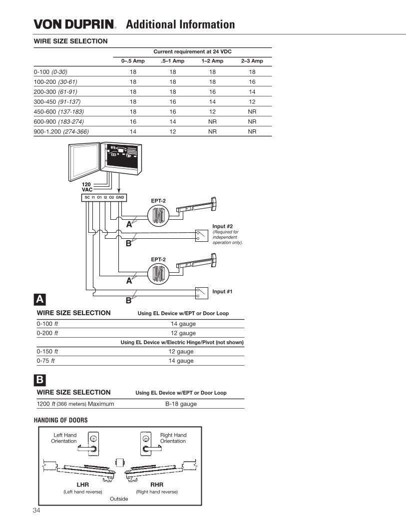
WIRE SIZE SELECTION
Current requirement at 24 VDC
0–.5 Amp .5–1 Amp 1–2 Amp 2–3 Amp
0-100 (0-30) 18 18 18 18
100-200 (30-61) 18 18 18 16
200-300 (61-91) 18 18 16 14
300-450 (91-137) 18 16 14 12
450-600 (137-183) 18 16 12 NR
600-900 (183-274) 16 14 NR NR
900-1.200 (274-366) 14 12 NR NR
120VAC
SC I1 O1 I2 O2 GNDEPT-2
EPT-2
Input #2(Required forindependentoperation only).
Input #1
A
B
A
B
HANDING OF DOORS
WIRE SIZE SELECTION Using EL Device w/EPT or Door Loop
0-100 ft 14 gauge
0-200 ft 12 gauge
Using EL Device w/Electric Hinge/Pivot (not shown)
0-150 ft 12 gauge
0-75 ft 14 gauge
WIRE SIZE SELECTION Using EL Device w/EPT or Door Loop
1200 ft (366 meters) Maximum B-18 gauge
A
B

35
Notes
©2005 Ingersoll-Rand Form VD-GN-1009 Rev. 07/05 Printed in USA
VON DUPRIN
2720 Tobey Drive,Indianapolis, IN 46219317-613-8944 phone317-613-8302 faxwww.vonduprin.comwww.irsecurityandsafety.com
Visit Von Duprin on the web
www.vonduprin.com
Canada / Latin AmericaCaribbean / MexicoIR Security & Safety1076 Lakeshore Road East Mississauga, Ontario L5E 1E4, Canada (905) 403-1800 (905) 278-1413 FAX (877) 590-4734
ChinaIR Security & Safety7F, Xuhuiyuan Building, 1089 Zhong Shan Nan 2 Road Shanghai 200030, P.R.China +(86) 21 5452-9898 +(86) 21 5410-1110 FAX www.irco.com.cn
North-East AsiaIR Security & Safety23/F, 625 King’s RoadNorthpoint, Hong Kong+(852) 2235-0600+(852) 2565-1409 FAX
South AsiaIngersoll-Rand South East Asia (Pte) Ltd.42 Benoi Road Singapore 629903 +65 6860-6850 +65 6861-9563 FAX
Australia / NZIR Architectural Hardware Ltd.P.O. Box 19-347 437 Rosebank Road, Avondale, Auckland, New Zealand +64 (0) 9-829-0550 +64 (0) 9-829-0552 FAX www.irarchitecturalhardware.co.nz
Europe / Middle-East / AfricaIR Security & Safety Ltd.Bescot CrescentWalsall, West Midlands WS1 4DLUnited Kingdom+44 (0)1922 707400+44 (0)1922 646303 FAXwww.irsecurityandsafety.co.uk
International Offices

OverviewThe Von Duprin 5100 Electric Strike has been designed and manufactured to meet the needs of locksmiths and security professionals. This easy-to-install electric strike was created for medium duty applications, specifically to control traffic flow through interior and exterior openings in retail and commercial environments.
Features and Benefits
• Three faceplates standard in every box • 12/24 dual-voltage • Fail-safe/fail-secure • Adjustable keeper • Internal solenoid • Non-handed • Backbox depth of 1 11/16” • Keeper depth of 1/2” • Mounting tabs • Retrofit kit • Illustrated installation instructions • Tamper resistant • 1 year electrical product warranty • Continuous duty operation • Heavy duty construction
5100 SeriesElectric Strikes
Syst
em C
ompo
nent
s
5100
Ser
ies
Elec
tric
Str
ikes
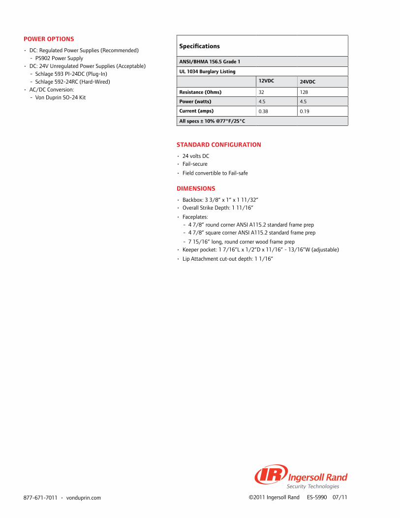
877-671-7011•vonduprin.com ©2011 Ingersoll Rand ES-5990 07/11
Specifications
ANSI/BHMA 156.5 Grade 1
UL 1034 Burglary Listing
12VDC 24VDC
Resistance (Ohms) 32 128
Power (watts) 4.5 4.5
Current (amps) 0.38 0.19
All specs ± 10% @77°F/25°C
POweR OPtIONS
• DC: Regulated Power Supplies (Recommended) - PS902 Power Supply
• DC: 24V Unregulated Power Supplies (Acceptable) - Schlage 593 PI-24DC (Plug-In) - Schlage 592-24RC (Hard-Wired)
• AC/DC Conversion: - Von Duprin SO-24 Kit
StANDARD CONFIGURAtION
• 24 volts DC • Fail-secure
• Field convertible to Fail-safe
DIMeNSIONS
• Backbox: 3 3/8” x 1” x 1 11/32” • Overall Strike Depth: 1 11/16”
• Faceplates: - 4 7/8” round corner ANSI A115.2 standard frame prep - 4 7/8” square corner ANSI A115.2 standard frame prep
- 7 15/16” long, round corner wood frame prep• Keeper pocket: 1 7/16”L x 1/2”D x 11/16” - 13/16”W (adjustable)
• Lip Attachment cut-out depth: 1 1/16”
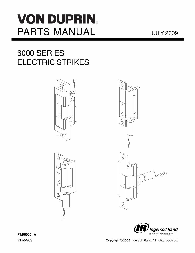
PARTS MANUAL
6000 SERIESELECTRIC STRIKES
JULY 2009
Copyright © 2009 Ingersoll-Rand. All rights reserved.
PM6000_A
VD-5563
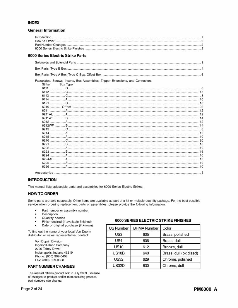
Page 2 of 24 PM6000_A
INDEX
General Information
Introduction .............................................................................................................................................................................. 2How to Order .......................................................................................................................................................................... 2Part Number Changes ............................................................................................................................................................. 26000 Series Electric Strike Finishes ........................................................................................................................................ 2
6000 Series Electric Strike Parts
Solenoids and Solenoid Parts ................................................................................................................................................. 3
Box Parts: Type B Box ............................................................................................................................................................ 4
Box Parts: Type A Box, Type C Box, Offset Box ................................................................................................................... 6
Faceplates, Screws, Inserts, Box Assemblies, Tripper Extensions, and ConnectorsStrike Box Type6111 ................. C ........................................................................................................................................................... 86112 ................. C .........................................................................................................................................................186113 ................. C ........................................................................................................................................................... 86114 ................. A .........................................................................................................................................................106121 ................. C .........................................................................................................................................................186210 ............. Offset .....................................................................................................................................................226211 ................. A .........................................................................................................................................................126211AL ............. A .........................................................................................................................................................126211WF ............ B .........................................................................................................................................................146212 ................. A .........................................................................................................................................................126212WF ............ B .........................................................................................................................................................146213 ................. C ........................................................................................................................................................... 86214 ................. A .........................................................................................................................................................106215 ................. A .........................................................................................................................................................106216 ................. C .........................................................................................................................................................206221 ................. B .........................................................................................................................................................166222 ................. A .........................................................................................................................................................106223 ................. B .........................................................................................................................................................166224 ................. A .........................................................................................................................................................106224AL ............. A .........................................................................................................................................................106225 ................. A .........................................................................................................................................................106226 ................. A .........................................................................................................................................................10
Accessories ............................................................................................................................................................................ 3
INTRODUCTION
This manual listsreplaceable parts and assemblies for 6000 Series Electric Strikes.
HOW TO ORDER
Some parts are sold separately. Other items are available as part of a kit or multiple quantity package. For the best possibleservice when ordering replacement parts or assemblies, please provide the following information:
• Part number or assembly number• Description• Quantity needed• Finish desired (if available finished)• Date of original purchase (if known)
6000 SERIES ELECTRIC STRIKE FINISHES
US Number BHMA Number Color
US3 605 Brass, polished
US4 606 Brass, dull
US10 612 Bronze, dull
US10B 640 Brass, dull (oxidized)
US32 629 Chrome, polished
US32D 630 Chrome, dull
To find out the name of your local Von Duprindistributor or sales representative, contact:
Von Duprin DivisionIngersoll-Rand Company2720 Tobey DriveIndianapolis, Indiana 46219Phone: (800) 999-0408Fax: (800) 999-0328
PART NUMBER CHANGES
This manual reflects product sold in July 2009. Becauseof changes to product and/or manufacturing process,part numbers can change.
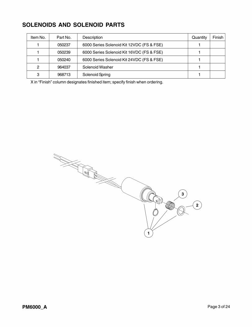
Page 3 of 24PM6000_A
Item No. Part No. Description Quantity Finish
1 050237 6000 Series Solenoid Kit 12VDC (FS & FSE) 1
1 050239 6000 Series Solenoid Kit 16VDC (FS & FSE) 1
1 050240 6000 Series Solenoid Kit 24VDC (FS & FSE) 1
2 964037 Solenoid Washer 1
3 968713 Solenoid Spring 1
X in “Finish” column designates finished item; specify finish when ordering.
SOLENOIDS AND SOLENOID PARTS
1
3
2
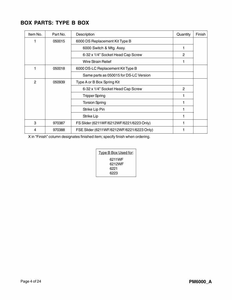
Page 4 of 24 PM6000_A
Item No. Part No. Description Quantity Finish
1 050015 6000 DS Replacement Kit Type B
6000 Switch & Mtg. Assy. 1
6-32 x 1/4” Socket Head Cap Screw 2
Wire Strain Relief 1
1 050018 6000 DS-LC Replacement Kit Type B
Same parts as 050015 for DS-LC Version
2 050939 Type A or B Box Spring Kit
6-32 x 1/4” Socket Head Cap Screw 2
Tripper Spring 1
Torsion Spring 1
Strike Lip Pin 1
Strike Lip 1
3 970387 FS Slider (6211WF/6212WF/6221/6223 Only) 1
4 970388 FSE Slider (6211WF/6212WF/6221/6223 Only) 1
X in “Finish” column designates finished item; specify finish when ordering.
BOX PARTS: TYPE B BOX
Type B Box Used for:
6211WF6212WF62216223
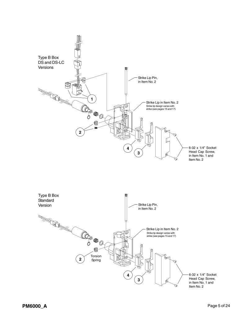
Page 5 of 24PM6000_A
Type B BoxDS and DS-LCVersions
1
2
6-32 x 1/4” SocketHead Cap Screw,in Item No. 1 andItem No. 2
Strike Lip Pin,in Item No. 2
43
Type B BoxStandardVersion
2
6-32 x 1/4” SocketHead Cap Screw,in Item No. 1 andItem No. 2
Strike Lip Pin,in Item No. 2
43
TorsionSpring
Strike lip design varies withstrike (see pages 15 and 17)
Strike lip design varies withstrike (see pages 15 and 17)
Strike Lip in Item No. 2
Strike Lip in Item No. 2
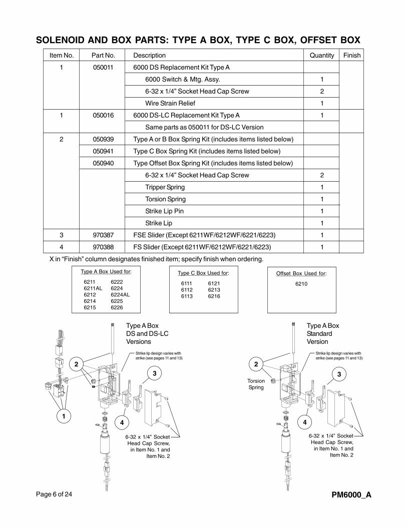
Page 6 of 24 PM6000_A
Offset Box Used for:
6210
Item No. Part No. Description Quantity Finish
1 050011 6000 DS Replacement Kit Type A
6000 Switch & Mtg. Assy. 1
6-32 x 1/4” Socket Head Cap Screw 2
Wire Strain Relief 1
1 050016 6000 DS-LC Replacement Kit Type A 1
Same parts as 050011 for DS-LC Version
2 050939 Type A or B Box Spring Kit (includes items listed below)
050941 Type C Box Spring Kit (includes items listed below)
050940 Type Offset Box Spring Kit (includes items listed below)
6-32 x 1/4” Socket Head Cap Screw 2
Tripper Spring 1
Torsion Spring 1
Strike Lip Pin 1
Strike Lip 1
3 970387 FSE Slider (Except 6211WF/6212WF/6221/6223) 1
4 970388 FS Slider (Except 6211WF/6212WF/6221/6223) 1
X in “Finish” column designates finished item; specify finish when ordering.
SOLENOID AND BOX PARTS: TYPE A BOX, TYPE C BOX, OFFSET BOX
Type A Box Used for:
6211 62226211AL 62246212 6224AL6214 62256215 6226
Type A BoxStandardVersion
TorsionSpring
2
3
6-32 x 1/4” SocketHead Cap Screw,
in Item No. 1 andItem No. 2
1
Type A BoxDS and DS-LCVersions
2
4
3
6-32 x 1/4” SocketHead Cap Screw,
in Item No. 1 andItem No. 2
Type C Box Used for:
6111 61216112 62136113 6216
4
Strike lip design varies withstrike (see pages 11 and 13)
Strike lip design varies withstrike (see pages 11 and 13)
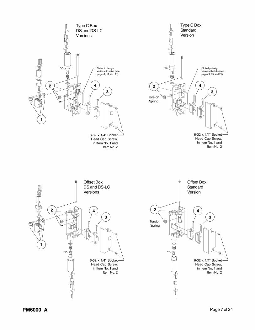
Page 7 of 24PM6000_A
TorsionSpring
Type C BoxStandardVersion
Type C BoxDS and DS-LCVersions
Offset BoxDS and DS-LCVersions
Offset BoxStandardVersion
2
1
4
3
6-32 x 1/4” SocketHead Cap Screw,in Item No. 1 and
Item No. 2
2 4
3
6-32 x 1/4” SocketHead Cap Screw,in Item No. 1 and
Item No. 2
1
2 4
3
6-32 x 1/4” SocketHead Cap Screw,in Item No. 1 and
Item No. 2
6-32 x 1/4” SocketHead Cap Screw,in Item No. 1 and
Item No. 2
2
TorsionSpring
4
3
Strike lip designvaries with strike (seepages 9, 19, and 21)
Strike lip designvaries with strike (seepages 9, 19, and 21)
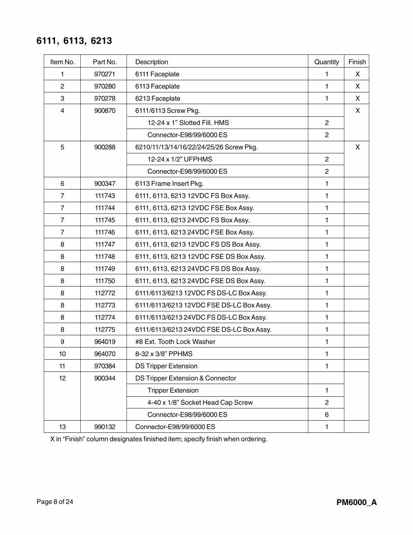
Page 8 of 24 PM6000_A
6111, 6113, 6213
Item No. Part No. Description Quantity Finish
1 970271 6111 Faceplate 1 X
2 970280 6113 Faceplate 1 X
3 970278 6213 Faceplate 1 X
4 900870 6111/6113 Screw Pkg. X
12-24 x 1” Slotted Fill. HMS 2
Connector-E98/99/6000 ES 2
5 900288 6210/11/13/14/16/22/24/25/26 Screw Pkg. X
12-24 x 1/2” UFPHMS 2
Connector-E98/99/6000 ES 2
6 900347 6113 Frame Insert Pkg. 1
7 111743 6111, 6113, 6213 12VDC FS Box Assy. 1
7 111744 6111, 6113, 6213 12VDC FSE Box Assy. 1
7 111745 6111, 6113, 6213 24VDC FS Box Assy. 1
7 111746 6111, 6113, 6213 24VDC FSE Box Assy. 1
8 111747 6111, 6113, 6213 12VDC FS DS Box Assy. 1
8 111748 6111, 6113, 6213 12VDC FSE DS Box Assy. 1
8 111749 6111, 6113, 6213 24VDC FS DS Box Assy. 1
8 111750 6111, 6113, 6213 24VDC FSE DS Box Assy. 1
8 112772 6111/6113/6213 12VDC FS DS-LC Box Assy. 1
8 112773 6111/6113/6213 12VDC FSE DS-LC Box Assy. 1
8 112774 6111/6113/6213 24VDC FS DS-LC Box Assy. 1
8 112775 6111/6113/6213 24VDC FSE DS-LC Box Assy. 1
9 964019 #8 Ext. Tooth Lock Washer 1
10 964070 8-32 x 3/8” PPHMS 1
11 970384 DS Tripper Extension 1
12 900344 DS Tripper Extension & Connector
Tripper Extension 1
4-40 x 1/8” Socket Head Cap Screw 2
Connector-E98/99/6000 ES 6
13 990132 Connector-E98/99/6000 ES 1
X in “Finish” column designates finished item; specify finish when ordering.
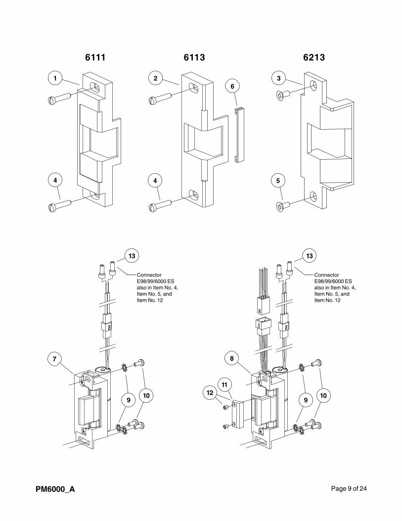
Page 9 of 24PM6000_A
6111
1 2 3
4 4
ConnectorE98/99/6000 ESalso in Item No. 4,Item No. 5, andItem No. 12
5
6
8
910
1112
13
6113 6213
ConnectorE98/99/6000 ESalso in Item No. 4,Item No. 5, andItem No. 12
13
7
910
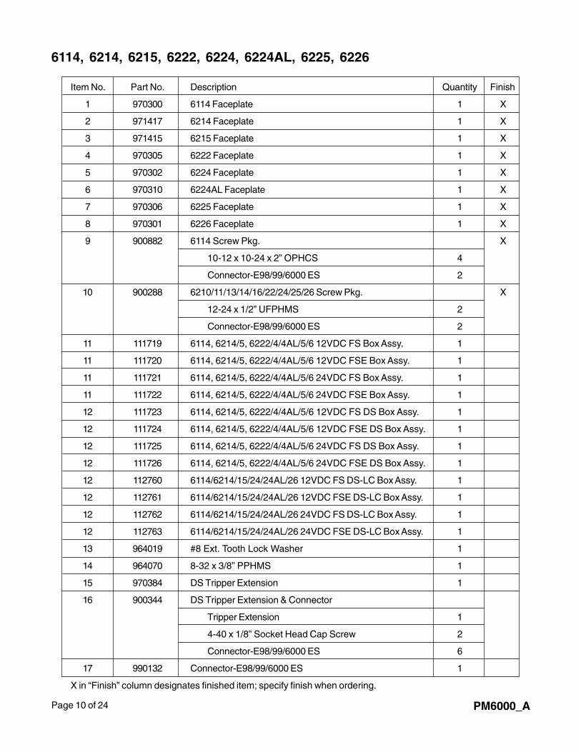
Page 10 of 24 PM6000_A
6114, 6214, 6215, 6222, 6224, 6224AL, 6225, 6226
Item No. Part No. Description Quantity Finish
1 970300 6114 Faceplate 1 X
2 971417 6214 Faceplate 1 X
3 971415 6215 Faceplate 1 X
4 970305 6222 Faceplate 1 X
5 970302 6224 Faceplate 1 X
6 970310 6224AL Faceplate 1 X
7 970306 6225 Faceplate 1 X
8 970301 6226 Faceplate 1 X
9 900882 6114 Screw Pkg. X
10-12 x 10-24 x 2” OPHCS 4
Connector-E98/99/6000 ES 2
10 900288 6210/11/13/14/16/22/24/25/26 Screw Pkg. X
12-24 x 1/2” UFPHMS 2
Connector-E98/99/6000 ES 2
11 111719 6114, 6214/5, 6222/4/4AL/5/6 12VDC FS Box Assy. 1
11 111720 6114, 6214/5, 6222/4/4AL/5/6 12VDC FSE Box Assy. 1
11 111721 6114, 6214/5, 6222/4/4AL/5/6 24VDC FS Box Assy. 1
11 111722 6114, 6214/5, 6222/4/4AL/5/6 24VDC FSE Box Assy. 1
12 111723 6114, 6214/5, 6222/4/4AL/5/6 12VDC FS DS Box Assy. 1
12 111724 6114, 6214/5, 6222/4/4AL/5/6 12VDC FSE DS Box Assy. 1
12 111725 6114, 6214/5, 6222/4/4AL/5/6 24VDC FS DS Box Assy. 1
12 111726 6114, 6214/5, 6222/4/4AL/5/6 24VDC FSE DS Box Assy. 1
12 112760 6114/6214/15/24/24AL/26 12VDC FS DS-LC Box Assy. 1
12 112761 6114/6214/15/24/24AL/26 12VDC FSE DS-LC Box Assy. 1
12 112762 6114/6214/15/24/24AL/26 24VDC FS DS-LC Box Assy. 1
12 112763 6114/6214/15/24/24AL/26 24VDC FSE DS-LC Box Assy. 1
13 964019 #8 Ext. Tooth Lock Washer 1
14 964070 8-32 x 3/8” PPHMS 1
15 970384 DS Tripper Extension 1
16 900344 DS Tripper Extension & Connector
Tripper Extension 1
4-40 x 1/8” Socket Head Cap Screw 2
Connector-E98/99/6000 ES 6
17 990132 Connector-E98/99/6000 ES 1
X in “Finish” column designates finished item; specify finish when ordering.
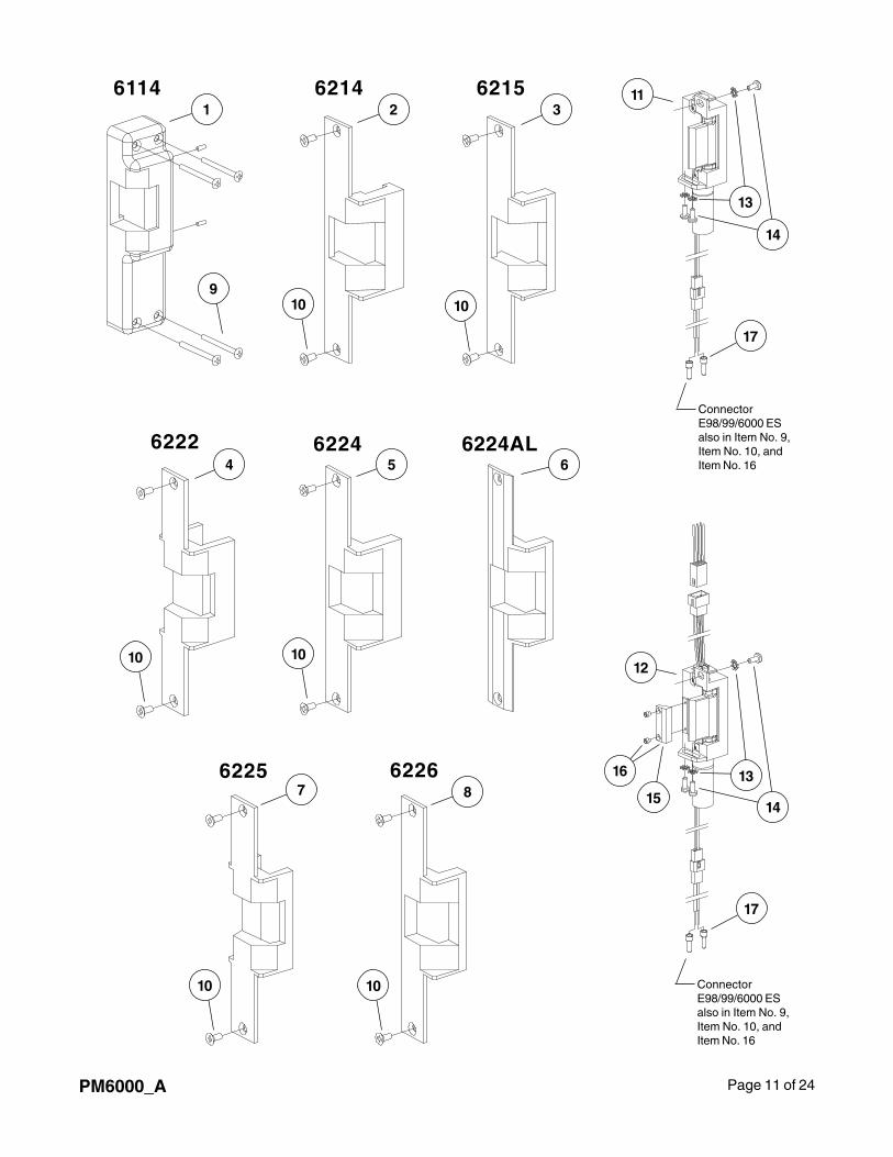
Page 11 of 24PM6000_A
6114 6214 6215
6222 6224 6224AL
6225 6226
1 2 3
4 5 6
7 8
910 10
10 10
10 10
11
12
13
13
14
1415
16
ConnectorE98/99/6000 ESalso in Item No. 9,Item No. 10, andItem No. 16
ConnectorE98/99/6000 ESalso in Item No. 9,Item No. 10, andItem No. 16
17
17
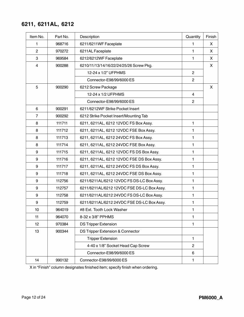
Page 12 of 24 PM6000_A
6211, 6211AL, 6212
Item No. Part No. Description Quantity Finish
1 968716 6211/6211WF Faceplate 1 X
2 970272 6211AL Faceplate 1 X
3 969584 6212/6212WF Faceplate 1 X
4 900288 6210/11/13/14/16/22/24/25/26 Screw Pkg. X
12-24 x 1/2” UFPHMS 2
Connector-E98/99/6000 ES 2
5 900290 6212 Screw Package X
12-24 x 1/2 UFPHMS 4
Connector-E98/99/6000 ES 2
6 900291 6211/6212WF Strike Pocket Insert
7 900292 6212 Strike Pocket Insert/Mounting Tab
8 111711 6211, 6211AL, 6212 12VDC FS Box Assy. 1
8 111712 6211, 6211AL, 6212 12VDC FSE Box Assy. 1
8 111713 6211, 6211AL, 6212 24VDC FS Box Assy. 1
8 111714 6211, 6211AL, 6212 24VDC FSE Box Assy. 1
9 111715 6211, 6211AL, 6212 12VDC FS DS Box Assy. 1
9 111716 6211, 6211AL, 6212 12VDC FSE DS Box Assy. 1
9 111717 6211, 6211AL, 6212 24VDC FS DS Box Assy. 1
9 111718 6211, 6211AL, 6212 24VDC FSE DS Box Assy. 1
9 112756 6211/6211AL/6212 12VDC FS DS-LC Box Assy. 1
9 112757 6211/6211AL/6212 12VDC FSE DS-LC Box Assy. 1
9 112758 6211/6211AL/6212 24VDC FS DS-LC Box Assy. 1
9 112759 6211/6211AL/6212 24VDC FSE DS-LC Box Assy. 1
10 964019 #8 Ext. Tooth Lock Washer 1
11 964070 8-32 x 3/8” PPHMS 1
12 970384 DS Tripper Extension 1
13 900344 DS Tripper Extension & Connector
Tripper Extension 1
4-40 x 1/8” Socket Head Cap Screw 2
Connector-E98/99/6000 ES 6
14 990132 Connector-E98/99/6000 ES 1
X in “Finish” column designates finished item; specify finish when ordering.
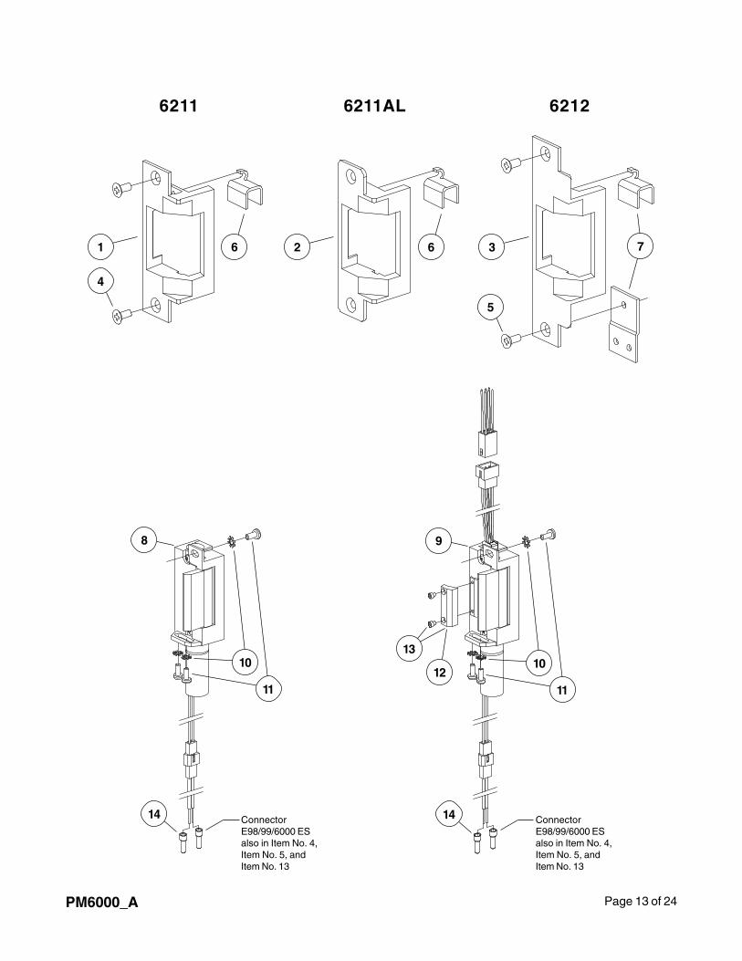
Page 13 of 24PM6000_A
6211 6211AL 6212
1 2 36
4
5
6 7
9
12
13
14 ConnectorE98/99/6000 ESalso in Item No. 4,Item No. 5, andItem No. 13
10
11
8
10
11
ConnectorE98/99/6000 ESalso in Item No. 4,Item No. 5, andItem No. 13
14
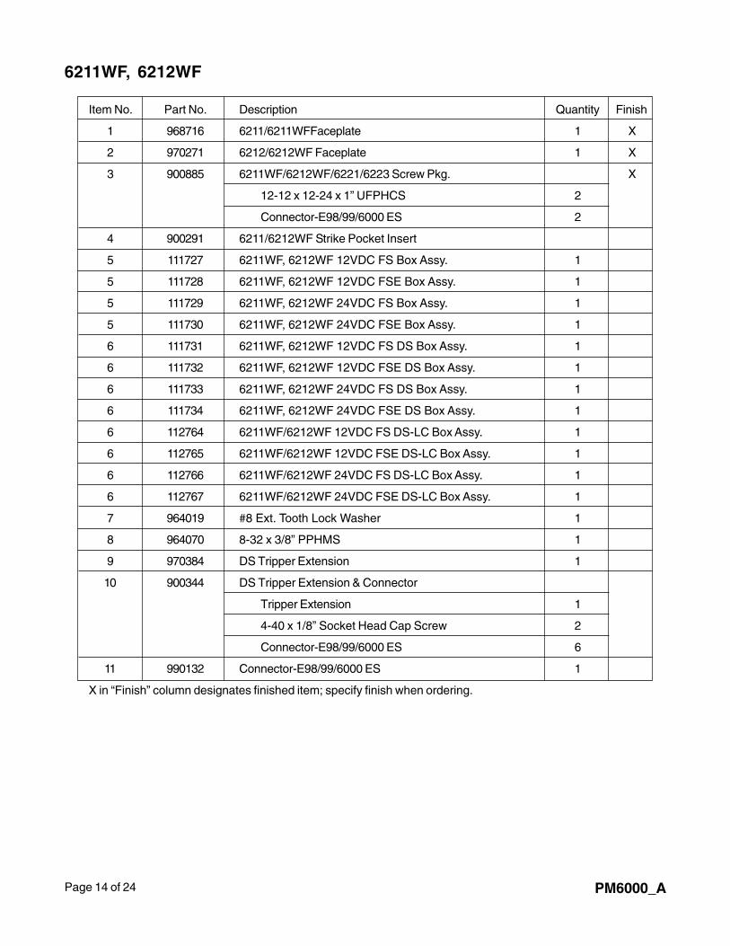
Page 14 of 24 PM6000_A
6211WF, 6212WF
Item No. Part No. Description Quantity Finish
1 968716 6211/6211WFFaceplate 1 X
2 970271 6212/6212WF Faceplate 1 X
3 900885 6211WF/6212WF/6221/6223 Screw Pkg. X
12-12 x 12-24 x 1” UFPHCS 2
Connector-E98/99/6000 ES 2
4 900291 6211/6212WF Strike Pocket Insert
5 111727 6211WF, 6212WF 12VDC FS Box Assy. 1
5 111728 6211WF, 6212WF 12VDC FSE Box Assy. 1
5 111729 6211WF, 6212WF 24VDC FS Box Assy. 1
5 111730 6211WF, 6212WF 24VDC FSE Box Assy. 1
6 111731 6211WF, 6212WF 12VDC FS DS Box Assy. 1
6 111732 6211WF, 6212WF 12VDC FSE DS Box Assy. 1
6 111733 6211WF, 6212WF 24VDC FS DS Box Assy. 1
6 111734 6211WF, 6212WF 24VDC FSE DS Box Assy. 1
6 112764 6211WF/6212WF 12VDC FS DS-LC Box Assy. 1
6 112765 6211WF/6212WF 12VDC FSE DS-LC Box Assy. 1
6 112766 6211WF/6212WF 24VDC FS DS-LC Box Assy. 1
6 112767 6211WF/6212WF 24VDC FSE DS-LC Box Assy. 1
7 964019 #8 Ext. Tooth Lock Washer 1
8 964070 8-32 x 3/8” PPHMS 1
9 970384 DS Tripper Extension 1
10 900344 DS Tripper Extension & Connector
Tripper Extension 1
4-40 x 1/8” Socket Head Cap Screw 2
Connector-E98/99/6000 ES 6
11 990132 Connector-E98/99/6000 ES 1
X in “Finish” column designates finished item; specify finish when ordering.
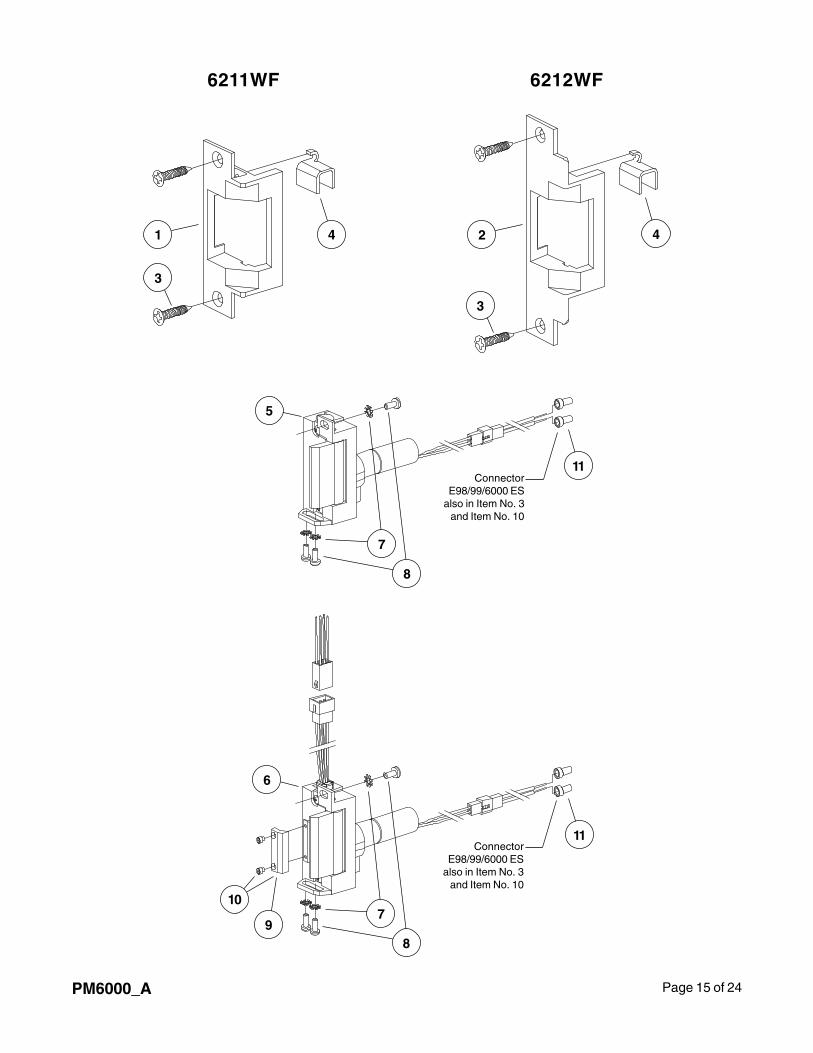
Page 15 of 24PM6000_A
6211WF 6212WF
1 24
3
3
4
6
7
89
10
11Connector
E98/99/6000 ESalso in Item No. 3
and Item No. 10
ConnectorE98/99/6000 ES
also in Item No. 3and Item No. 10
7
8
5
11
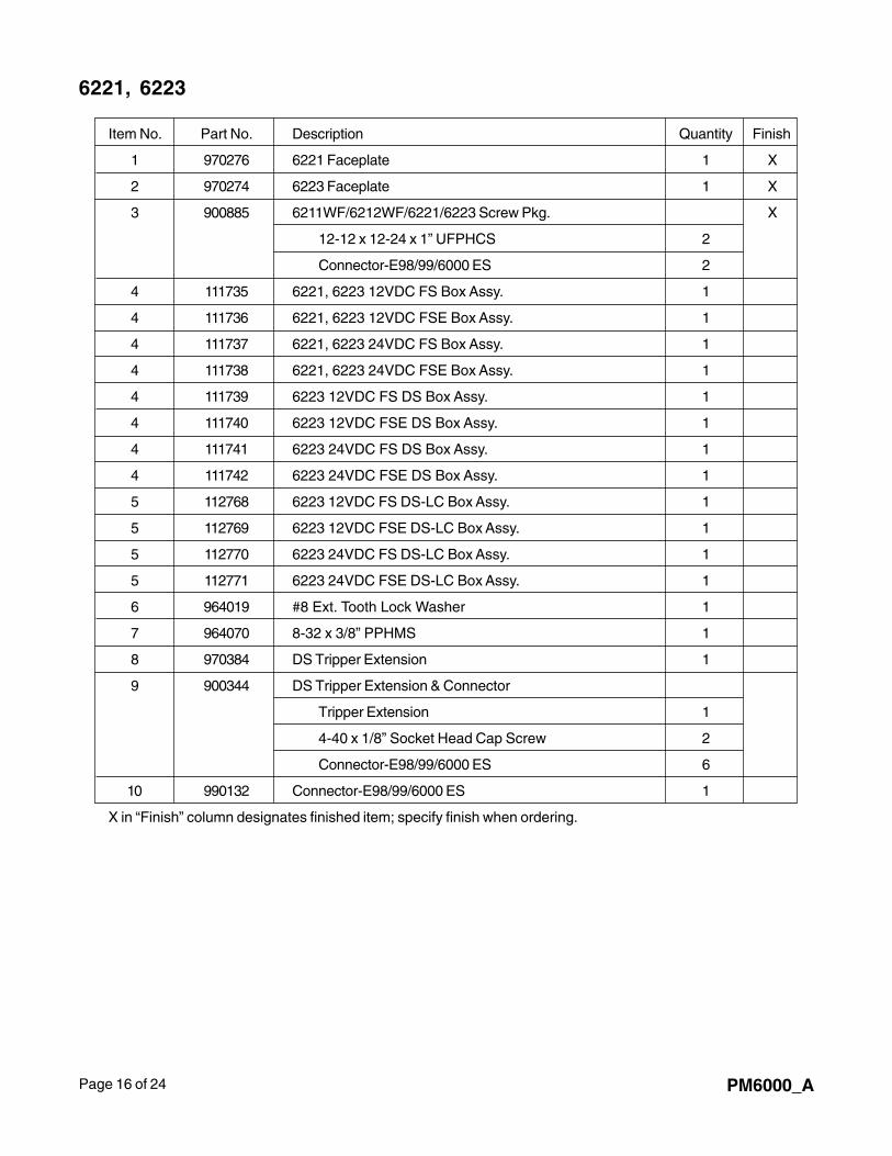
Page 16 of 24 PM6000_A
6221, 6223
Item No. Part No. Description Quantity Finish
1 970276 6221 Faceplate 1 X
2 970274 6223 Faceplate 1 X
3 900885 6211WF/6212WF/6221/6223 Screw Pkg. X
12-12 x 12-24 x 1” UFPHCS 2
Connector-E98/99/6000 ES 2
4 111735 6221, 6223 12VDC FS Box Assy. 1
4 111736 6221, 6223 12VDC FSE Box Assy. 1
4 111737 6221, 6223 24VDC FS Box Assy. 1
4 111738 6221, 6223 24VDC FSE Box Assy. 1
4 111739 6223 12VDC FS DS Box Assy. 1
4 111740 6223 12VDC FSE DS Box Assy. 1
4 111741 6223 24VDC FS DS Box Assy. 1
4 111742 6223 24VDC FSE DS Box Assy. 1
5 112768 6223 12VDC FS DS-LC Box Assy. 1
5 112769 6223 12VDC FSE DS-LC Box Assy. 1
5 112770 6223 24VDC FS DS-LC Box Assy. 1
5 112771 6223 24VDC FSE DS-LC Box Assy. 1
6 964019 #8 Ext. Tooth Lock Washer 1
7 964070 8-32 x 3/8” PPHMS 1
8 970384 DS Tripper Extension 1
9 900344 DS Tripper Extension & Connector
Tripper Extension 1
4-40 x 1/8” Socket Head Cap Screw 2
Connector-E98/99/6000 ES 6
10 990132 Connector-E98/99/6000 ES 1
X in “Finish” column designates finished item; specify finish when ordering.
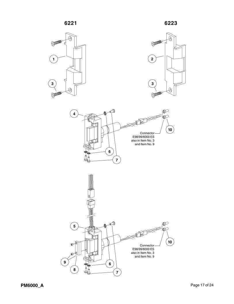
Page 17 of 24PM6000_A
6221 6223
1
3
2
3
5
ConnectorE98/99/6000 ES
also in Item No. 3and Item No. 9
10
6
78
9
4
ConnectorE98/99/6000 ES
also in Item No. 3and Item No. 9
10
6
7
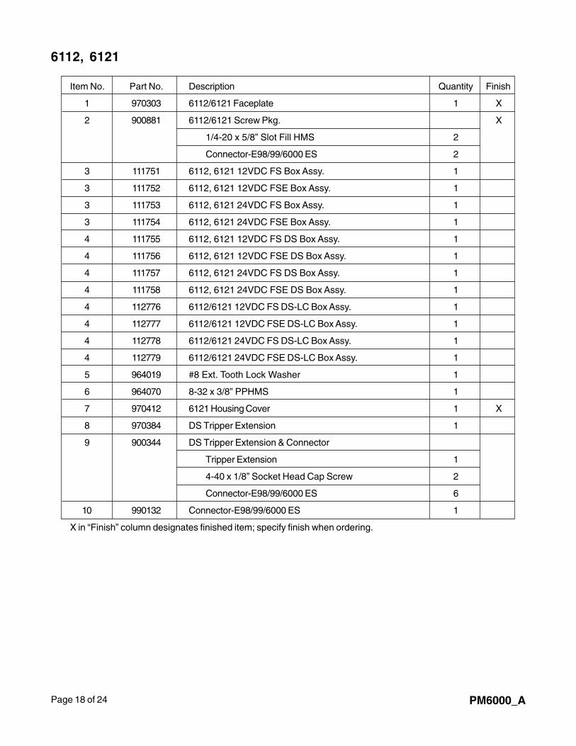
Page 18 of 24 PM6000_A
6112, 6121
Item No. Part No. Description Quantity Finish
1 970303 6112/6121 Faceplate 1 X
2 900881 6112/6121 Screw Pkg. X
1/4-20 x 5/8” Slot Fill HMS 2
Connector-E98/99/6000 ES 2
3 111751 6112, 6121 12VDC FS Box Assy. 1
3 111752 6112, 6121 12VDC FSE Box Assy. 1
3 111753 6112, 6121 24VDC FS Box Assy. 1
3 111754 6112, 6121 24VDC FSE Box Assy. 1
4 111755 6112, 6121 12VDC FS DS Box Assy. 1
4 111756 6112, 6121 12VDC FSE DS Box Assy. 1
4 111757 6112, 6121 24VDC FS DS Box Assy. 1
4 111758 6112, 6121 24VDC FSE DS Box Assy. 1
4 112776 6112/6121 12VDC FS DS-LC Box Assy. 1
4 112777 6112/6121 12VDC FSE DS-LC Box Assy. 1
4 112778 6112/6121 24VDC FS DS-LC Box Assy. 1
4 112779 6112/6121 24VDC FSE DS-LC Box Assy. 1
5 964019 #8 Ext. Tooth Lock Washer 1
6 964070 8-32 x 3/8” PPHMS 1
7 970412 6121 Housing Cover 1 X
8 970384 DS Tripper Extension 1
9 900344 DS Tripper Extension & Connector
Tripper Extension 1
4-40 x 1/8” Socket Head Cap Screw 2
Connector-E98/99/6000 ES 6
10 990132 Connector-E98/99/6000 ES 1
X in “Finish” column designates finished item; specify finish when ordering.
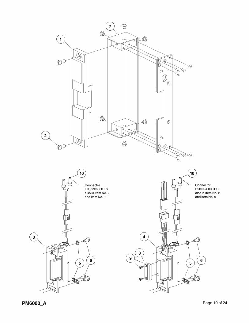
Page 19 of 24PM6000_A
ConnectorE98/99/6000 ESalso in Item No. 2and Item No. 9
4
56
89
10
ConnectorE98/99/6000 ESalso in Item No. 2and Item No. 9
10
3
1
2
7
56
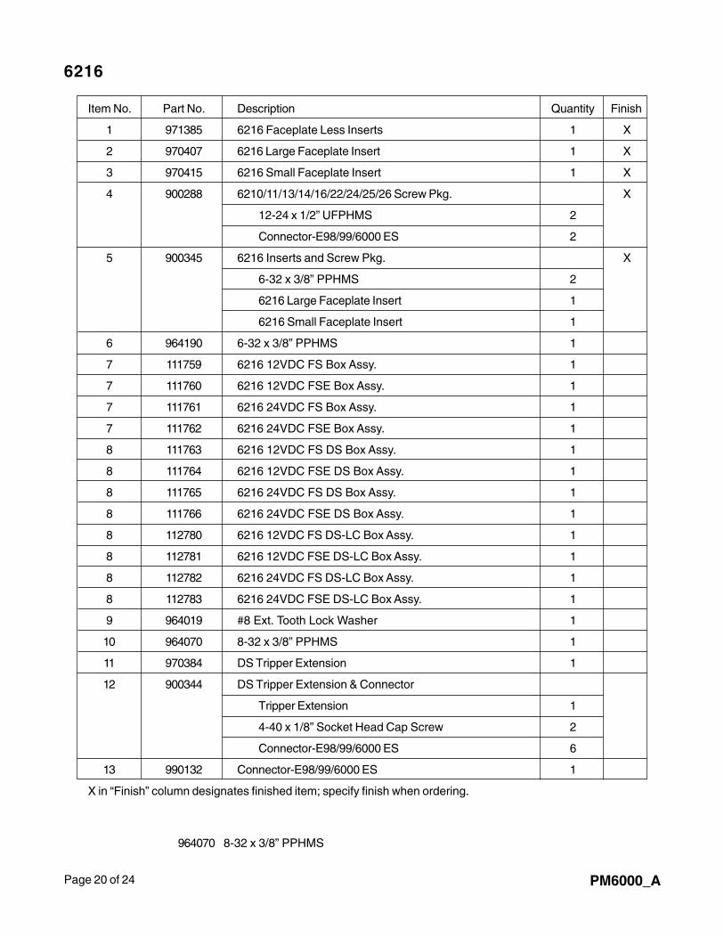
Page 20 of 24 PM6000_A
6216
Item No. Part No. Description Quantity Finish
1 971385 6216 Faceplate Less Inserts 1 X
2 970407 6216 Large Faceplate Insert 1 X
3 970415 6216 Small Faceplate Insert 1 X
4 900288 6210/11/13/14/16/22/24/25/26 Screw Pkg. X
12-24 x 1/2” UFPHMS 2
Connector-E98/99/6000 ES 2
5 900345 6216 Inserts and Screw Pkg. X
6-32 x 3/8” PPHMS 2
6216 Large Faceplate Insert 1
6216 Small Faceplate Insert 1
6 964190 6-32 x 3/8” PPHMS 1
7 111759 6216 12VDC FS Box Assy. 1
7 111760 6216 12VDC FSE Box Assy. 1
7 111761 6216 24VDC FS Box Assy. 1
7 111762 6216 24VDC FSE Box Assy. 1
8 111763 6216 12VDC FS DS Box Assy. 1
8 111764 6216 12VDC FSE DS Box Assy. 1
8 111765 6216 24VDC FS DS Box Assy. 1
8 111766 6216 24VDC FSE DS Box Assy. 1
8 112780 6216 12VDC FS DS-LC Box Assy. 1
8 112781 6216 12VDC FSE DS-LC Box Assy. 1
8 112782 6216 24VDC FS DS-LC Box Assy. 1
8 112783 6216 24VDC FSE DS-LC Box Assy. 1
9 964019 #8 Ext. Tooth Lock Washer 1
10 964070 8-32 x 3/8” PPHMS 1
11 970384 DS Tripper Extension 1
12 900344 DS Tripper Extension & Connector
Tripper Extension 1
4-40 x 1/8” Socket Head Cap Screw 2
Connector-E98/99/6000 ES 6
13 990132 Connector-E98/99/6000 ES 1
X in “Finish” column designates finished item; specify finish when ordering.
964070 8-32 x 3/8” PPHMS
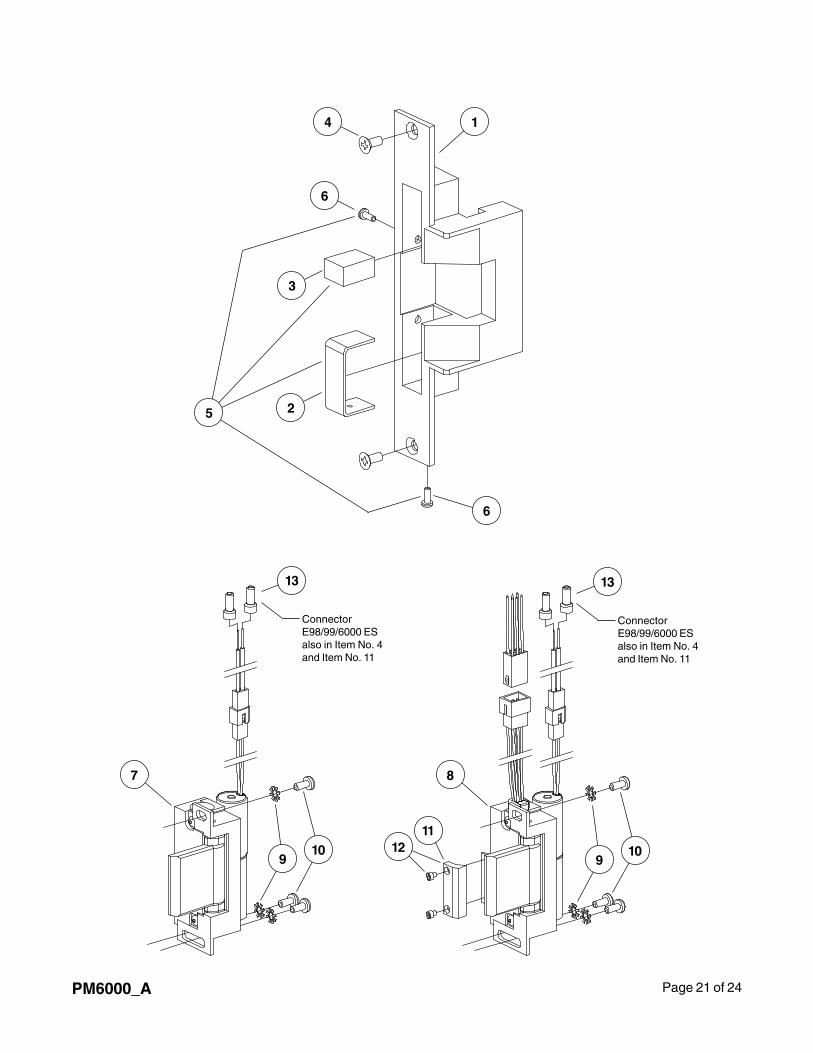
Page 21 of 24PM6000_A
1
3
4
5 2
8
1112
910
910
7
ConnectorE98/99/6000 ESalso in Item No. 4and Item No. 11
13
ConnectorE98/99/6000 ESalso in Item No. 4and Item No. 11
13
6
6
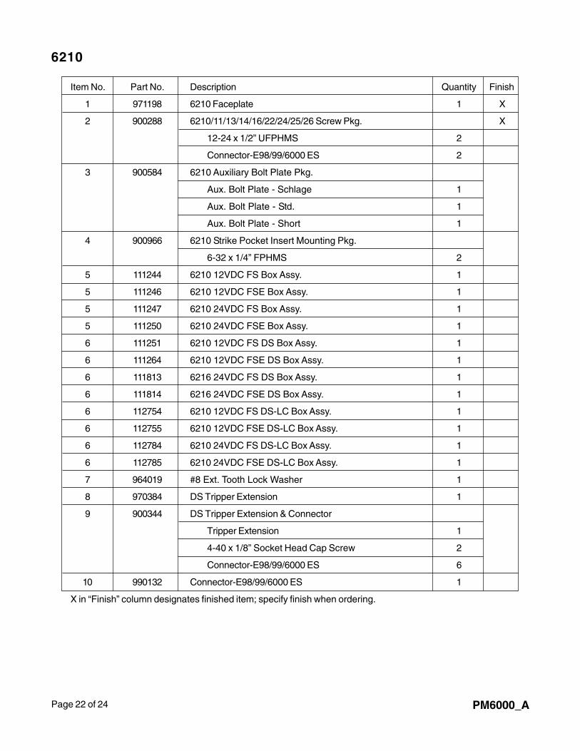
Page 22 of 24 PM6000_A
6210
Item No. Part No. Description Quantity Finish
1 971198 6210 Faceplate 1 X
2 900288 6210/11/13/14/16/22/24/25/26 Screw Pkg. X
12-24 x 1/2” UFPHMS 2
Connector-E98/99/6000 ES 2
3 900584 6210 Auxiliary Bolt Plate Pkg.
Aux. Bolt Plate - Schlage 1
Aux. Bolt Plate - Std. 1
Aux. Bolt Plate - Short 1
4 900966 6210 Strike Pocket Insert Mounting Pkg.
6-32 x 1/4” FPHMS 2
5 111244 6210 12VDC FS Box Assy. 1
5 111246 6210 12VDC FSE Box Assy. 1
5 111247 6210 24VDC FS Box Assy. 1
5 111250 6210 24VDC FSE Box Assy. 1
6 111251 6210 12VDC FS DS Box Assy. 1
6 111264 6210 12VDC FSE DS Box Assy. 1
6 111813 6216 24VDC FS DS Box Assy. 1
6 111814 6216 24VDC FSE DS Box Assy. 1
6 112754 6210 12VDC FS DS-LC Box Assy. 1
6 112755 6210 12VDC FSE DS-LC Box Assy. 1
6 112784 6210 24VDC FS DS-LC Box Assy. 1
6 112785 6210 24VDC FSE DS-LC Box Assy. 1
7 964019 #8 Ext. Tooth Lock Washer 1
8 970384 DS Tripper Extension 1
9 900344 DS Tripper Extension & Connector
Tripper Extension 1
4-40 x 1/8” Socket Head Cap Screw 2
Connector-E98/99/6000 ES 6
10 990132 Connector-E98/99/6000 ES 1
X in “Finish” column designates finished item; specify finish when ordering.
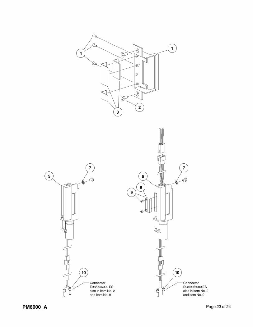
Page 23 of 24PM6000_A
1
23
4
5 6
7 7
89
ConnectorE98/99/6000 ESalso in Item No. 2and Item No. 9
10
ConnectorE98/99/6000 ESalso in Item No. 2and Item No. 9
10

Page 24 of 24 PM6000_A


