VORT NRG EC / EC EH 600 - 800 - 1500 - 2000 - 2500 Manuale di uso e attivazione Operating and commissioning instructions Manuel d’utilisation et de mise en marche VORTICE LIMITED Beeches House - Eastern Avenue Burton on Trent DE13 0BB Tel. (+44) 1283-492949 Fax (+44) 1283-544121 UNITED KINGDOM VORTICE ELETTROSOCIALI S.p.A. Strada Cerca, 2 - frazione di Zoate 20067 TRIBIANO (MI) Tel. (+39) 02-90.69.91 Fax (+39) 02-90.64.625 ITALIA COD. 5.471.084.301 15/02/2016 VORTICE FRANCE 15-33, Rue Le Corbusier Europarc CS 30007 90046 CRETEIL CEDEX FRANCE
Transcript
VORT NRG EC / EC EH600 - 800 - 1500 - 2000 - 2500
Manuale di uso e attivazioneOperating and commissioning instructionsManuel d’utilisation et de mise en marche
VORTICE LIMITEDBeeches House - Eastern AvenueBurton on TrentDE13 0BBTel. (+44) 1283-492949Fax (+44) 1283-544121UNITED KINGDOM
VORTICE FRANCE15-33, Rue Le Corbusier EuroparcCS 3000790046 CRETEIL CEDEXFRANCE
2
Prima di usare il prodotto leggere attentamentele istruzioni contenute nel presente libretto.
Vortice non potrà essere ritenuta responsabileper eventuali danni a persone o cose causati
dal mancato rispetto delle indicazioni di seguitoelencate, la cui osservanza assicurerà invece la
durata e l’affidabilità, elettrica e meccanica,dell’apparecchio.
Conservare sempre questo libretto istruzioni.
Before installing and using your product, read theseinstructions carefully. Vortice will not accept anyresponsibility for damage to property or personalharm resulting from failure to abide by conditions
given in this booklet.Following these instructions will ensure long servicelife and overall electrical and mechanical reliability.
Keep this instruction booklet in a safe place forreference purposes.
Avant d’utiliser l’appareil, lire attentivement lesinstructions données dans cette notice.
La société Vortice ne pourra être tenue pourresponsable des dommages causés aux personnes
ou aux biens si les consignes ci-dessous ne sont pas respectées car elles garantissent la durée de vieet la fiabilité électrique et mécanique de l’appareil.
Toujours conserver ce livret d’instructions.
Vor der Benutzung des Gerätes muss die vorliegendeAnleitung aufmerksam durchgelesen werden.Vortice haftet nicht für Personen- und/oder
Sachschäden, die auf die Nichtbeachtung der indiesem Handbuch enthaltenen und für einen
korrekten Betrieb, die mechanische und elektrische Sicherheit sowie eine lange Lebensdauer
des Gerätes wichtigen Hinweise bzw. Anleitungenzurückzuführen sind.
Bewahren Sie diese Betriebsanleitung gewissenhaft auf.
Prije korištenja proizvoda, pažljivo pročitajte upute kojesadrži ovaj priručnik.
Tvrtka Vortice se ne može smatrati odgovornom zaeventualnu štetu nanesenu osobama ili stvarima uslijed
nepoštivanja uputa koje se u nastavku navode, apridržavanjem kojih se osigurava trajnost te električna i
mehanička pouzdanost uređaja.Brižljivo čuvajte ove upute za uporabu.
Před použitím výrobku si pozorně přečtěte pokyny obsažené v této příručce.
Podnik Vortice neodpovídá za případná zranění osob nebopoškození věcí způsobené nedodržením dále uvedenýchpokynů; jejich dodržování naopak zajistí dlouhodobouživotnost výrobku, jak elektrickou, tak i mechanickou.
Tento návod k obsluze si proto uschovejte.
Pred používaním spotrebiča si pozorne prečítajte všetkypokyny v tomto návode.
Vortice nebude zodpovedať za žiadne poranenia osôb aniškody na majetku spôsobené nedodržaním upozorneníuvedených v nasledujúcom texte, ktorých dodržiavanie,
naopak, zaručí dlhodobú elektrickú a mechanickúspoľahlivosť, spotrebiča.
Tento návod na používanie si starostlivo odložte.
I RECEIVING THE EQUIPMENT ................................................................................................................52I.1 Checks on receipt ...................................................................................................................................52I.2 Unpacking................................................................................................................................................52I.3 Storage ....................................................................................................................................................52
II INSTALLATION........................................................................................................................................52II.1 Handling..................................................................................................................................................52II.2 Space required .......................................................................................................................................53II.3 Positioning ..............................................................................................................................................54
III GENERAL OPERATION .........................................................................................................................54III.1 General ..................................................................................................................................................54III.2 OPERATING SEQUENCE ......................................................................................................................54III.3 CONTROL MODES................................................................................................................................55III.3.a. VORT NRG EC .......................................................................................................................................55III.3.b. ECO :......................................................................................................................................................55III.3.c. DIVA........................................................................................................................................................55III.3.d. LOBBY® ................................................................................................................................................55
III.4. COMPOSITION......................................................................................................................................56III.5.b. SEASON CONTROL ..............................................................................................................................57
III.5. POSITIONING OF THE CONTROL PANEL ELEMENTS........................................................................57III.5.a. ECO/DIVA/LOBBY CONTROL ...............................................................................................................57
IV.3. CONNECTION OF TEMPERATURE SENSORS....................................................................................58IV.2. VORT NRG EC DIAGRAM ....................................................................................................................58
IV. ELECTRICAL WIRING...........................................................................................................................58IV.1. ELECTRICAL POWER SUPPLY............................................................................................................58VI.4 CONNECTION TERMINALS - VORT NRG EC FIRST/DIVA/LOBBY .....................................................59IV.5. Electrical connection and operation of the plate heat exchanger.........................................................60IV.5.a. VORT NRG EC version ...........................................................................................................................60IV.5.b. FIRST PREMIUM INFINITE AND SMART version..................................................................................60
IV.6. Auto defrost ...........................................................................................................................................61IV.6.a. VORT NRG EC version ...........................................................................................................................61IV.6.b. FIRST PREMIUM INFINITE and VORT NRG EC EH version..................................................................61
IV.7. Connection of the filter pressure switches ............................................................................................61IV.8. Connection of the fan pressure switches ..............................................................................................61IV.9. Connection of pressure senders for LOBBY® ......................................................................................62IV.10. Connection of motors ..........................................................................................................................62IV.11. CO2 sender connection.......................................................................................................................62IV.12. Night Cooling .......................................................................................................................................63IV.13. Changeover coil ...................................................................................................................................63IV.14. Direct expansion coil for cooling only or reversible coil ......................................................................64IV.15. Electric heater battery..........................................................................................................................64IV.16. Defrost heater battery ..........................................................................................................................65IV.17. Fire protection function........................................................................................................................65IV.18. Dehumidification function ....................................................................................................................65IV.19. MODBUS/WEB/BACNET connection..................................................................................................66IV.20. Repeater connection............................................................................................................................66IV.21. LON......................................................................................................................................................67
ENGLISH
49
50
ENGLISH
V. PARAMETER DEFINITION ......................................................................................................................67V.1. Control (integral or remote control).........................................................................................................67V.2. Example parameter settings...................................................................................................................68V.3. Standard settings (operator menu) .........................................................................................................68V.3.a. Operation Mode menu ............................................................................................................................69V.3.c. Ventilation control menu..........................................................................................................................70V.3.b. Temperature control menu......................................................................................................................70V.3.d. Timer setting menu .................................................................................................................................71
V.4. Modification of operator parameters (password 3333 required) ............................................................72V.4.a. Setting different time and date clocks ....................................................................................................72
V.4.a.1. Date and time o the CORRIGO controller[(1) section V.3.d]...................................................................72V.4.a.2. Programming system operation times [(2) (3) chapter V.3.d]..................................................................72V.4.a.3. Vacation period [(4) section V.3.d] (password 3333 required).................................................................72
V.4.b. Modifying the speed/pressure for LS and HS operation........................................................................72V.4.b.1. STANDARD (ECO)/DIVA [(5) section V.3.c] ............................................................................................72V.4.b.2. LOBBY [(5) section V.3.c] ........................................................................................................................72
V.4.c. Modifying the temperature setpoint........................................................................................................73V.4.d. Forced shutdown of control panel or forced LS or HS run of remote control .......................................73V.4.e. Language selection .................................................................................................................................73
V.5. Intermediate settings (function level) ......................................................................................................73V.5.a. Configuration menu with function level access ......................................................................................73V.5.b. Modification of function parameters (password 2222 required).............................................................74
V.5.b.1. System control mode...............................................................................................................................74V.5.b.2. Ventilation parameters .............................................................................................................................74V.5.b.3. CO2 setpoint for DIVA QUATTRO option ................................................................................................74
V.6. Administrator settings.............................................................................................................................74V.6.a. Configuration menu with admin level access .........................................................................................75
V.7. Modification of function parameters.......................................................................................................75V.7.a. MODBUS.................................................................................................................................................75
V.7.a.1. Repeaters and EXO communication .......................................................................................................76V.7.a.2. WEB communication ...............................................................................................................................76V.8.a.3. BACNET IP communication with BASC type ..........................................................................................76V.8.a.4. LON communication (if CORRIGO with LON option)..............................................................................77V.8.a.5. Activation of fire protection function.........................................................................................................77V.8.a.6. Activation of the dehumidification function ..............................................................................................77
VI. PROBLEM SOLVING .............................................................................................................................78VI.1. Different types of fault ...........................................................................................................................78VI.2. Alarms list ..............................................................................................................................................79VI.3. Cancelling the “Servicing required” alarm ............................................................................................80
VII. MAINTENANCE ....................................................................................................................................81VII.1. Essential maintenance..........................................................................................................................81VII.2. Battery replacement .............................................................................................................................81
VIII. APPENDICES .....................................................................................................................................82VIII.1. Control diagram...................................................................................................................................82VIII.2. Connection of motors for VORT NRG EC / EC EH 600 - 800 ............................................................83VIII.3. Connection of motors for VORT NRG EC / EC EH 1500-2000-2500 .................................................84VORT NRG EC / EC EH 1500........................................................................................................................85VORT NRG EC / EC EH 800..........................................................................................................................85VORT NRG EC / EC EH 600..........................................................................................................................85
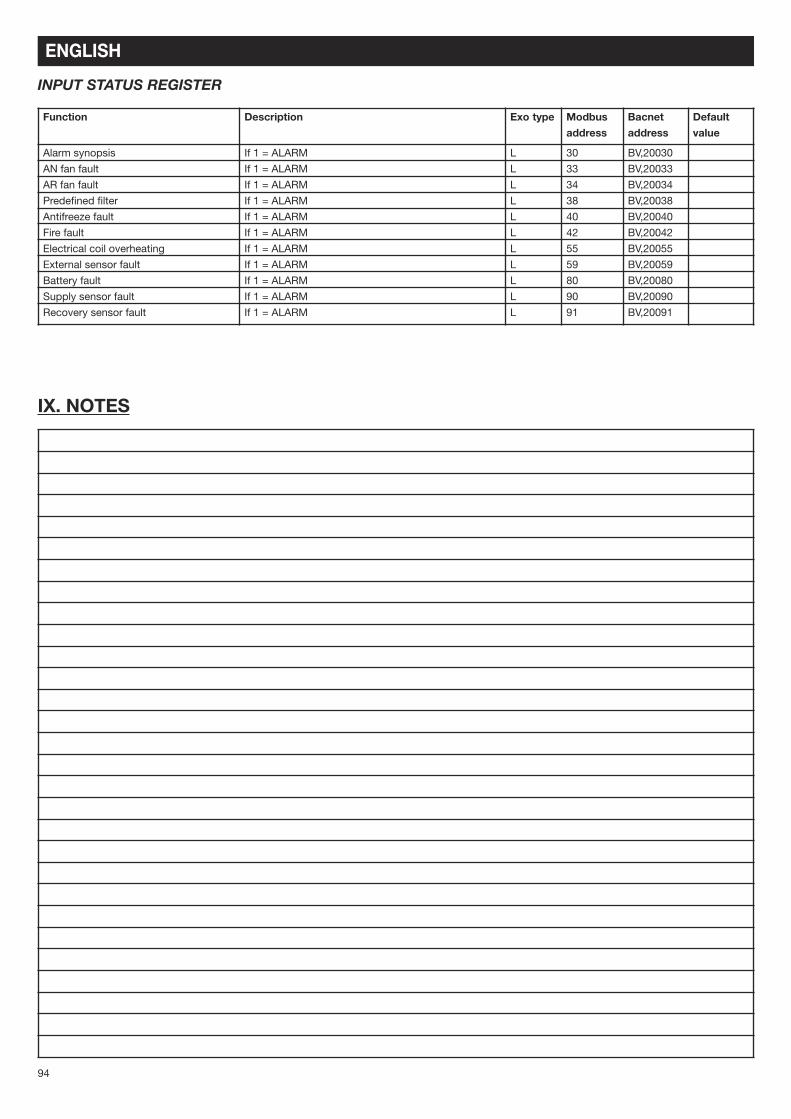
IX. NOTES...................................................................................................................................................94INPUT STATUT REGISTER .................................................................................................................................94
ENGLISH
52
I RECEIVING THE EQUIPMENTSystems are supplied fixed to guides or plates and wrapped in plastic film.
I.1 Checks on receiptOn receipt of the equipment, carefully inspect the packaging and the contents. If damaged, record an accuratedescription of the damage on the delivery note.
I.2 UnpackingWhen unpacking the equipment, check the following :- The total number of packages is present.- All the accessories (dampers, covers, electrical equipment. etc.) ordered are present.
After unpacking the equipment, all packaging materials should be disposed of in accordance with the applicableregulations.Dispose of waste materials responsibly.
I.3 StorageThe equipment must be stored in a dry enclosed area, at a temperature between -20 and 40°C; note that the packagingdoes not offer sufficient protection against bad weather.
II INSTALLATION
II.1 HandlingThe units must only be moved to their installation position.
If the equipment is handled using a fork-lift truck, ensure the forks support the load-bearing structure. Check that the loadcapacity of the handling equipment used is suitable for the weight of the equipment received (refer to the weight data inthe manual).
If the equipment is handled using a crane, use 4 lifting ropes of the length indicated. The ropes must be at least as longas the greatest distance between two attachment points.
If the length + width + height > 5 metres _ the packing crate must lifted using a sling bar.
SAFETY INSTRUCTIONS
In compliance with the current standards, the machine should be installed only by technical personnel who arequalified to work on equipment of this type.
Use the required personal protection equipment to avoid risk of injury from electrical, mechanical (injury from contactwith steel sheets, sharp edges, etc.) eye protection (UVC hazard; wear goggles to EN170) or noise hazards.Do not use this equipment for any purpose other than that for which it is designed. This machine may be usedexclusively for the distribution of air that is free of hazardous substances.The machine should be handled in accordance with the indications given in the relative section of this manual.The machine must be connected to earth in accordance with the applicable regulations. Never start a unit that hasnot been connected to earth.Before carrying out any work on a unit, make sure that its is switched off and before opening panels or doors, waituntil all the moving parts have come to a stop (damper, fan and rotary heat exchanger).During operation, all panels, inspection hatched and doors must always be fitted and closed. The unit must only be started or stopped using the proximity switch.Safety and control devices must not be removed, by-passed or deactivated.When working on the unit, be aware that certain components can reach high temperatures (water coil or electricheater).The system must be installed in accordance with fire prevention regulations.All waste materials must be disposed of in accordance with the applicable regulations.The manufacturer accepts no liability for damages ensuing from the incorrect use of the equipment, unauthorizedrepair or modification, or failure to follow the instructions given in this manual.
ENGLISH
53
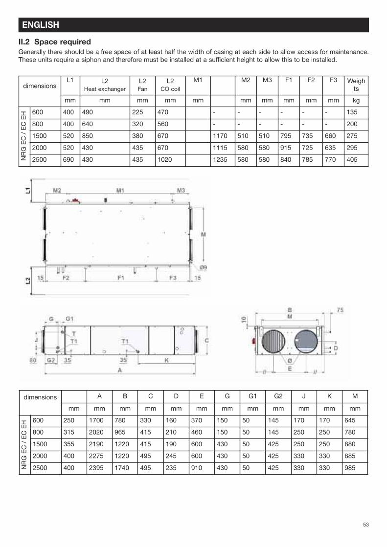
II.2 Space requiredGenerally there should be a free space of at least half the width of casing at each side to allow access for maintenance.These units require a siphon and therefore must be installed at a sufficient height to allow this to be installed.
II.3 PositioningThe system must be suspended above or supported on a sufficiently rigid surface (use a vibration damping mounts ifnecessary). For ductwork connections, select duct sections to suit the dimensions of the flexible hoses, which should beproperly tensioned. The ducts should be insulated and the first accessories should be installed at a distance of 2.5 timesthe duct diameter from the unit (T junction, etc.). Install the unit in such a way that internal components cannot bedamaged by bad weather or ambient temperature either during the installation or subsequent use of the unit.
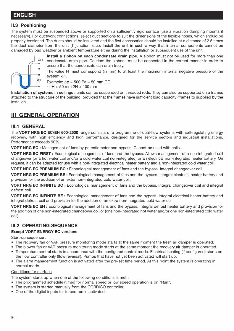
Install a siphon on each condensate drain pipe. A siphon must not be used for more than onecondensate drain pipe. Caution: the siphons must be connected in the correct manner in order toensure that the condensate can drain freely.
The value H must correspond (in mm) to at least the maximum internal negative pressure of thesystem x 1.
Example: Dp = 500 Pa = 50 mm CE_ H > 50 mm 2H > 100 mm
Installation of systems in ceilings : units can be suspended on threaded rods. They can also be supported on a framesattached to the structure of the building, provided that the frames have sufficient load capacity (frames to supplied by theinstaller).
III GENERAL OPERATION
III.1 GENERALThe VORT NRG EC EC/EH 600-2500 range consists of a programme of dual-flow systems with self-regulating energyrecovery, with high efficiency and high performance, designed for the service sectors and industrial installations.Performance exceeds 90%.
VORT NRG EC : Management of fans by potentiometer and bypass. Cannot be used with coils.VORT NRG EC FIRST : Econological management of fans and the bypass. Allows management of a non-integrated coilchangeover (or a hot water coil and/or a cold water coil non-integrated) or an electrical non-integrated heater battery. Onrequest, it can be adapted for use with a non-integrated electrical heater battery and a non-integrated cold water coil.
VORT NRG EC PREMIUM BC : Econological management of fans and the bypass. Integral changeover coil.VORT NRG EC PREMIUM BE : Econological management of fans and the bypass. Integral electrical heater battery andprovision for the addition of an extra non-integrated cold water coil.
VORT NRG EC INFINITE BC : Econological management of fans and the bypass. Integral changeover coil and integraldefrost coil.
VORT NRG EC INFINITE BE : Econological management of fans and the bypass. Integral electrical heater battery andintegral defrost coil and provision for the addition of an extra non-integrated cold water coil.
VORT NRG EC EH : Econological management of fans and the bypass. Integral defrost heater battery and provision forthe addition of one non-integrated changeover coil or (one non-integrated hot water and/or one non-integrated cold watercoil).
III.2 OPERATING SEQUENCEExcept VORT ENERGY EC versionsStart-up sequence :• The recovery fan or VAR pressure monitoring mode starts at the same moment the fresh air damper is operated.• The blower fan or VAR pressure monitoring mode starts at the same moment the recovery air damper is operated.• Temperature control starts in accordance with the configured control mode. Electrical heating (if configured) starts onthe flow controller only (flow reversal). Pumps that have not yet been activated will start up.
• The alarm management function is activated after the pre-set time period. At this point the system is operating innormal mode.
Conditions for startup :
The system starts up when one of the following conditions is met :• The programmed schedule (timer) for normal speed or low speed operation is on “Run”.• The system is started manually from the CORRIGO controller.• One of the digital inputs for forced run is activated.
ENGLISH
55
Shutdown sequence :
The system shutdown procedure is as follows :• Deactivation of the alarm management function.• Deactivation of electrical heating (if configured).• After a certain time interval (individually pre-set for each fan), the fans are switched off.• The fresh air and return air dampers are closed.• The signals sent to the actuators are re-set to zero and the pumps are stopped.
Conditions for shutdown :
The system shuts down when one of the following conditions is met :• The programmed schedule (timer) for normal speed or low speed operation is on “Stop” and the forced run signal isalso on “Stop”.
• Activation of the external shutdown command.• The system is shut down manually from the CORRIGO controller.• Intervention of an alarm configured with the supplementary shutdown function. The system will restart automaticallyonce the alarm has been reset.
III.3 CONTROL MODES
III.3.a. VORT NRG EC1 speed that can be controlled by potentiometerEach fan can be controlled individually by a potentiometer integrated in the system.
Possibility to add a remote forced shutdown control connected in series to the contactor (not supplied).
III.3.b. ECO :1 or 2 speeds that can be controlled via the display/remote control/external control “VENTIL. MODE (%)”Setting of a minimum speed (LS - 1/2) and a maximum speed (HS - 1/1 as %.
Equipped with factory-set timer :• (HS - 1/1) from 06:00 to 22:00• (LS - 1/2) from 22:00 to 06:00
Possibility to add a remote forced run control (LS - 1/2) or (HS - 1/1)
Possibility to add a remote forced shutdown control
III.3.c. DIVAProportional ventilation between two flow rates (HS/LS) with “AUTOMATIC CO2 CONTROL MODE”.Setting of a minimum speed (LS - 1/2) and a maximum speed (HS - 1/1) as %.
The CO2 setpoint is factory-set to 1000 ppm (in accordance with RT2012).
The transition between (LS - 1/2) and (HS - 1/1) is controlled in accordance with the CO2level.Equipped with continuous run factory-set timer (LS - 1/2).
Possibility to add a remote forced run control (LS - 1/2) or (HS - 1/1) (NO volt-free contacts)
Possibility to add a remote forced shutdown control (NO volt-free contacts)
Note : In order for the CO2 control to function correctly, the system must meet the following conditions :• Timer (HS - 1/1) on 0 (inactive) (Normal speed timer)• Timer (LS - 1/2) in operation (Low speed timer)• Forced run (HS - 1/1) and Forced shutdown not activated.
III.3.d. LOBBY®
Constant ventilation pressure. (Pa) “CONSTANT Pa MODE”Setting a constant pressure (Pa).Equipped with continuous running factory-set timer (LS - 1/2);Possibility to add a remote forced run control (LS - 1/2)Possibility to add a remote forced shutdown control
ENGLISH
!
Pa
Pa
Pa
flow rate
flow rate
flow rate
GV Speed
PV Speed
GV Speed
PV Speed
Constant pressure
PV flow rate
56
III.4. COMPOSITION
ENGLISH
CONTROLSSRG FR SM SBD DBE FS
SEG
SSG VS CO/BE HEAT EXCHANGERSDG VR
The sensor group is not integrated in the SEASON version
NAME DescriptionVS Blower fanVR Recovery fanSSG Recovery air pressure switch or recovery air pressure sender for LOBBY versionSDG 230/24 V power transformerSEG Duct recovery sensorSRG CO2 sensor (DIVA version only)SDB Lockable proximity switchFS Supply filterFR Recovery filterSM 100% bypass servomotorCO/BE Changeover heater battery or electric heater battery (depending on version)DBE Defrost heater battery for INFINITE model only
57
ENGLISH
III.5. POSITIONING OF THE CONTROL PANEL ELEMENTS
III.5.a. ECO/DIVA/LOBBY CONTROL
N° NAME Description1 DEPFS Supply filter pressure switch2 DEPS or TRPS Supply pressure switch or supply pressure sender for LOBBY version3 DEPR or TRPR Recovery air pressure switch or recovery air pressure sender for LOBBY version4 TRAFO 230/24 V power transformer5 SRG Duct recovery sensor6 CO2 CO2 sensor (DIVA version only)7 IPC Lockable proximity switch8 K1 Electrical heating coil contactor9 KD Contactor for the electric defrost heater battery10 CONTROLLER CORRIGO E283W3 Controller11 TERMINAL BOARD Control terminal board12 THA/THS/THSD The overheating and antifreeze thermostats are integrated in the panel
TH1= External temperature for heat recovery viaheat exchanger (factory setting: 18°C)TH2= External temperature for cold recovery viaheat exchanger (factory setting: 24°C)TH3= Temperature of emission for defrost viabypass (factory setting: 5°C) -> Do not change thissetting
IV.3. CONNECTION OF TEMPERATURE SENSORSExcept VORT NRG EC versionThe temperature sensors are connected directly to the controller• SSG : Duct supply sensor connected to Agnd(30) and AI1(31)• SEG : Duct external sensor connected to Agnd(30) and AI1(32)• SDG : Duct defrost sensor connected to Agnd(33) and AI1(34)• SRG : Duct recovery sensor connected to Agnd(33) and AI1(35)• SBD : Defrost heater battery sensor connected to Agnd(36) and AI4(37) on SMART and INFINITE versions (replacedby 1030 Ohm resistance on other versions)
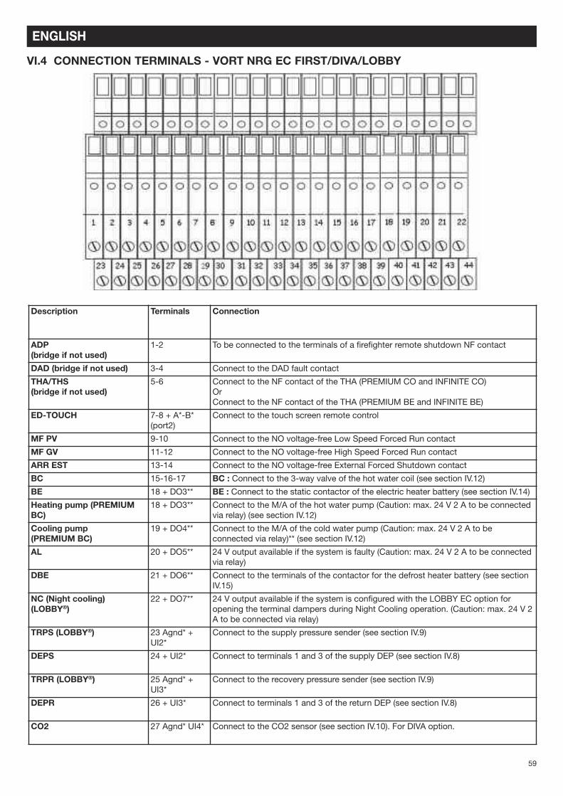
1-2 To be connected to the terminals of a firefighter remote shutdown NF contact
DAD (bridge if not used) 3-4 Connect to the DAD fault contact
THA/THS (bridge if not used)
5-6 Connect to the NF contact of the THA (PREMIUM CO and INFINITE CO) Or Connect to the NF contact of the THA (PREMIUM BE and INFINITE BE)
ED-TOUCH 7-8 + A*-B* (port2)
Connect to the touch screen remote control
MF PV 9-10 Connect to the NO voltage-free Low Speed Forced Run contact
MF GV 11-12 Connect to the NO voltage-free High Speed Forced Run contact
ARR EST 13-14 Connect to the NO voltage-free External Forced Shutdown contact
BC 15-16-17 BC : Connect to the 3-way valve of the hot water coil (see section IV.12)
BE 18 + DO3** BE : Connect to the static contactor of the electric heater battery (see section IV.14)
Heating pump (PREMIUMBC)
18 + DO3** Connect to the M/A of the hot water pump (Caution: max. 24 V 2 A to be connectedvia relay) (see section IV.12)
Cooling pump (PREMIUM BC)
19 + DO4** Connect to the M/A of the cold water pump (Caution: max. 24 V 2 A to beconnected via relay)** (see section IV.12)
AL 20 + DO5** 24 V output available if the system is faulty (Caution: max. 24 V 2 A to be connectedvia relay)
DBE 21 + DO6** Connect to the terminals of the contactor for the defrost heater battery (see sectionIV.15)
NC (Night cooling)(LOBBY®)
22 + DO7** 24 V output available if the system is configured with the LOBBY EC option foropening the terminal dampers during Night Cooling operation. (Caution: max. 24 V 2A to be connected via relay)
TRPS (LOBBY®) 23 Agnd* +UI2*
Connect to the supply pressure sender (see section IV.9)
DEPS 24 + UI2* Connect to terminals 1 and 3 of the supply DEP (see section IV.8)
TRPR (LOBBY®) 25 Agnd* +UI3*
Connect to the recovery pressure sender (see section IV.9)
DEPR 26 + UI3* Connect to terminals 1 and 3 of the return DEP (see section IV.8)
CO2 27 Agnd* UI4* Connect to the CO2 sensor (see section IV.10). For DIVA option.
60
ENGLISH
Description Terminals Connection
BF 28-29-30 BF : Connect to the 3-way valve of the cold water coil (see section IV.12)
DEP FS DEP FR
31-32 33-34
Connect to terminals 1 and 3 of the DEP Supply Filter (see section IV.7) Connect to terminals 1 and 3 of the DEP Recovery Filter (see section IV.7)
RMS 35 + DO1** Connect to terminals 1 and 2 of the motorised supply damper
RMR 36 + DO2** Connect to terminals 1 and 2 of the motorised recovery damper
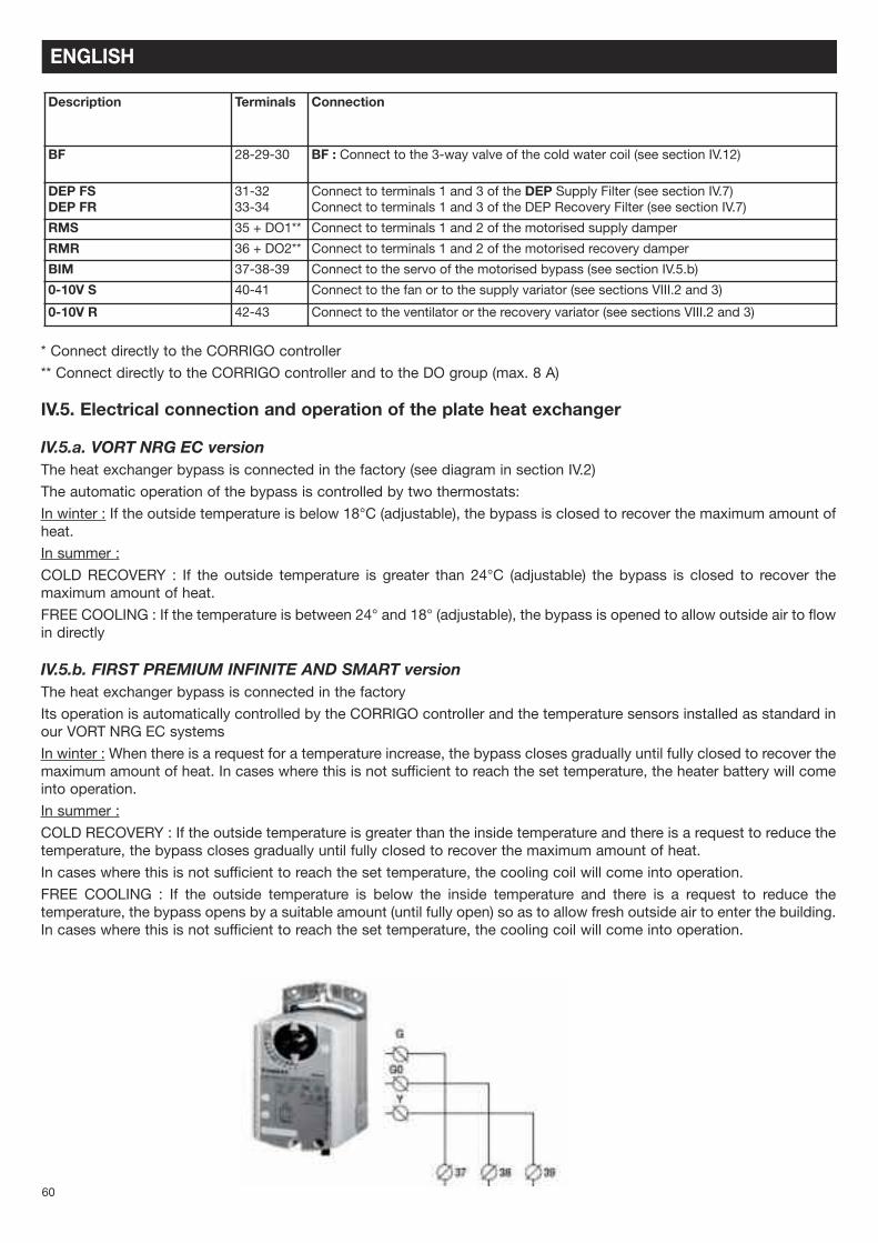
BIM 37-38-39 Connect to the servo of the motorised bypass (see section IV.5.b)
0-10V S 40-41 Connect to the fan or to the supply variator (see sections VIII.2 and 3)
0-10V R 42-43 Connect to the ventilator or the recovery variator (see sections VIII.2 and 3)
* Connect directly to the CORRIGO controller
** Connect directly to the CORRIGO controller and to the DO group (max. 8 A)
IV.5. Electrical connection and operation of the plate heat exchanger
IV.5.a. VORT NRG EC versionThe heat exchanger bypass is connected in the factory (see diagram in section IV.2)
The automatic operation of the bypass is controlled by two thermostats:
In winter : If the outside temperature is below 18°C (adjustable), the bypass is closed to recover the maximum amount ofheat.
In summer :
COLD RECOVERY : If the outside temperature is greater than 24°C (adjustable) the bypass is closed to recover themaximum amount of heat.
FREE COOLING : If the temperature is between 24° and 18° (adjustable), the bypass is opened to allow outside air to flowin directly
IV.5.b. FIRST PREMIUM INFINITE AND SMART versionThe heat exchanger bypass is connected in the factory
Its operation is automatically controlled by the CORRIGO controller and the temperature sensors installed as standard inour VORT NRG EC systems
In winter : When there is a request for a temperature increase, the bypass closes gradually until fully closed to recover themaximum amount of heat. In cases where this is not sufficient to reach the set temperature, the heater battery will comeinto operation.
In summer :
COLD RECOVERY : If the outside temperature is greater than the inside temperature and there is a request to reduce thetemperature, the bypass closes gradually until fully closed to recover the maximum amount of heat.
In cases where this is not sufficient to reach the set temperature, the cooling coil will come into operation.
FREE COOLING : If the outside temperature is below the inside temperature and there is a request to reduce thetemperature, the bypass opens by a suitable amount (until fully open) so as to allow fresh outside air to enter the building.In cases where this is not sufficient to reach the set temperature, the cooling coil will come into operation.
61
IV.6. Auto defrost
IV.6.a. VORT NRG EC versionDefrosting is achieved by opening the bypass the moment the defrost temperature (SDG) falls below 5° C (thermostatinstalled on exhaust duct). The moment the temperature exceeds the threshold value of +5° C, the bypass re-closes.
IV.6.b. FIRST PREMIUM INFINITE and VORT NRG EC EH versionThis non-modifiable function is automatically controlled by the CORRIGO controller program and by the sensors fitted asstandard in all our dual flow systems. Defrosting is achieved by opening the bypass the moment the defrost temperature(SDG) falls below 5° C (sensor installed on exhaust duct). If opening the bypass is not sufficient to defrost the heatexchanger (if the outside temperature is below -10° C), the flow rate of the fresh air fan will be modulated to maintain thetemperature at the defrost sensor at 5° C.
For INFINITE BE and INFINITE BC versions : the defrost heater battery is installed next to the fresh air intake, upstreamof the plate heat exchanger. This maintains the temperature at the heat exchanger at –5°C, thereby reducing the risk offrost forming while keeping the bypass as closed as possible. This ensures that the system operates at maximumefficiency. If the action of the defrost heater battery is not in itself sufficient to defrost the heat exchanger, first bypassmodulation and then fan modulation will be implemented, as described above.
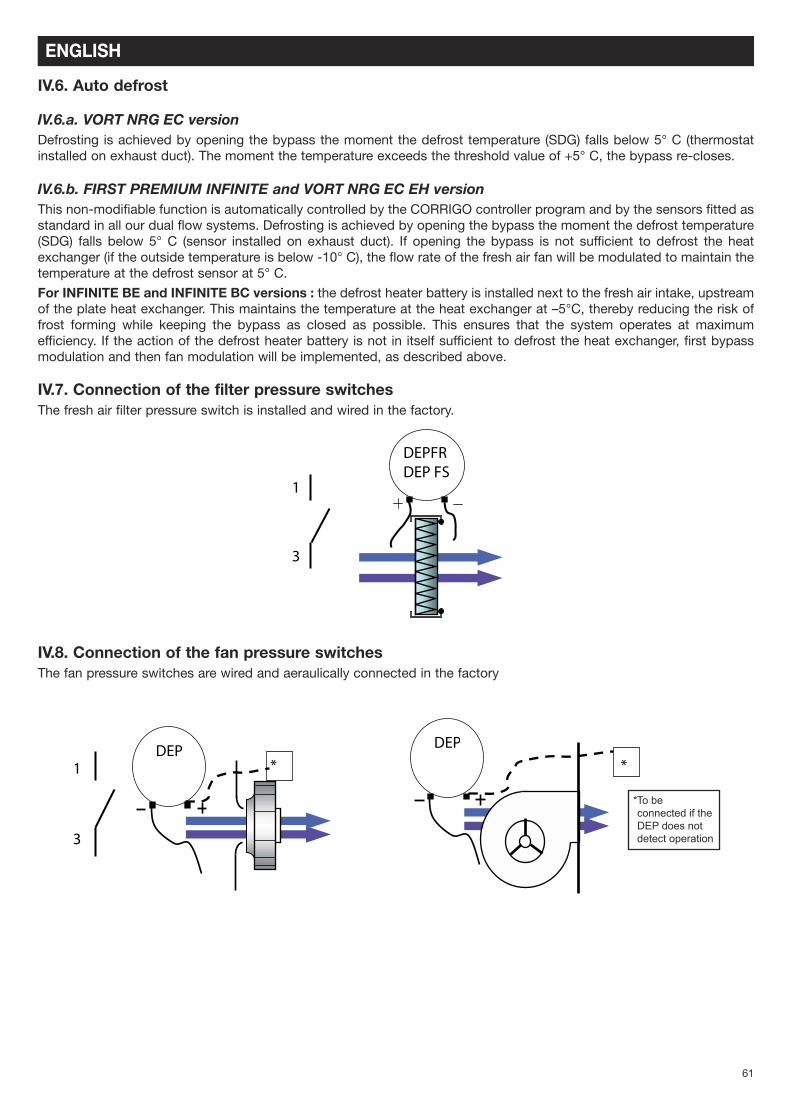
IV.7. Connection of the filter pressure switchesThe fresh air filter pressure switch is installed and wired in the factory.
IV.8. Connection of the fan pressure switchesThe fan pressure switches are wired and aeraulically connected in the factory
3
1
DEPFRDEP FS
ENGLISH
DEP DEP* *1
3
*To beconnected if theDEP does notdetect operation
62
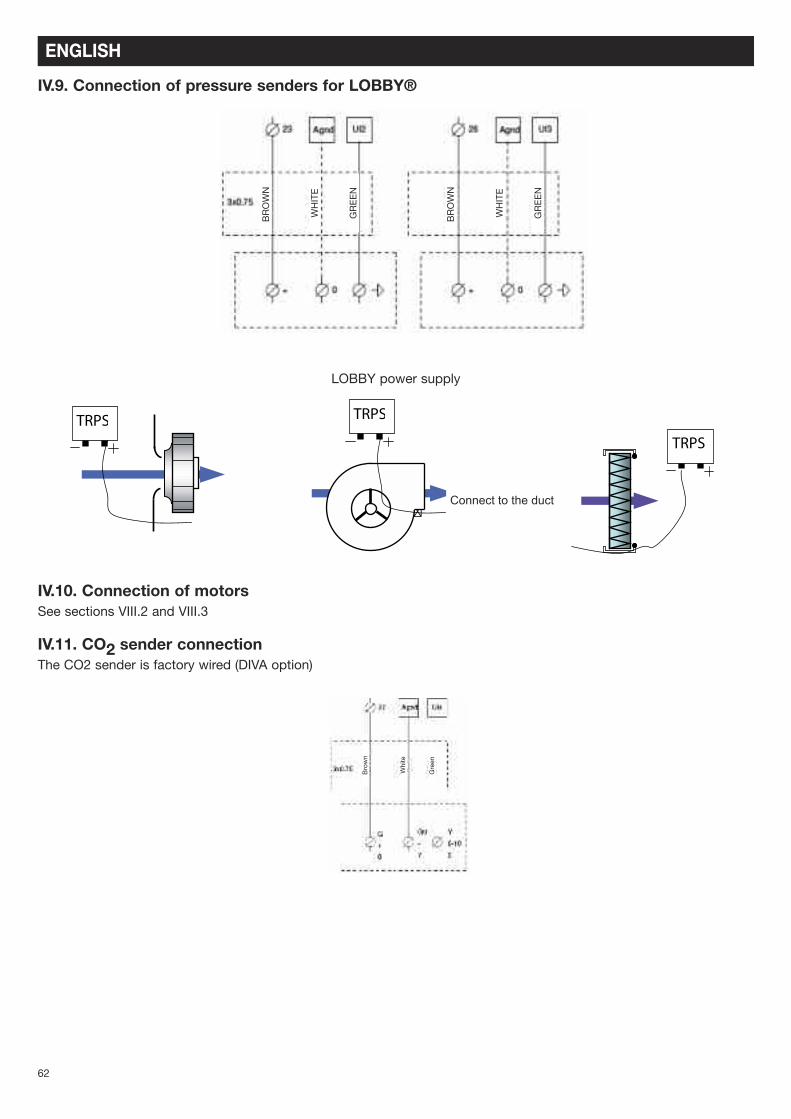
IV.9. Connection of pressure senders for LOBBY®
LOBBY power supply
IV.10. Connection of motorsSee sections VIII.2 and VIII.3
IV.11. CO2 sender connectionThe CO2 sender is factory wired (DIVA option)
TRPSTRPS
�
TRPS
ENGLISH
Connect to the duct
Brown
BROWN
WHITE
GREEN
BROWN
WHITE
GREEN
White
Green
63
IV.12. Night CoolingThis function is used in summer to cool building interiors at night using outside air. This helps reduce the quantity of coldair required during the daytime. The Night Cooling function only operates from 00:00 to 07:00. During Night Cooling, thehot and cold outputs are locked to 0 V. The heat exchanger delivers exclusively fresh air. On termination of the NightCooling stage, the heating is locked to 0V for 60 minutes.
Conditions of operation : definable parameters in section V.5.b.2• The external temperature exceeds 22° C during daytime• The timers are set to PV and for shutdown between 00:00 and 07:00.• The external temperature is below 18° C during Night Cooling operation• The external temperature exceeds 10° C during Night Cooling operation• The ambient room temperature exceeds 18° C
During Night Cooling, the fans run at 85% of full speed. This speed is settable (see section V.5.b.2).
For LOBBY versions, a 24 V output (to be connected by relay) is available across terminals 22 and DO7 to force openingof the area dampers during Night Cooling.
IV.13. Changeover coilFor PREMIUM BC and INFINITE BC systems. Provision must be made for collection of condensate via a siphon.
Be careful not to impede opening of the access doors (with pipes, cables, etc.)
The coil is already installed in the system, the antifreeze thermostat is connected. The 3-way valve must be connectedelectrically. If a cooling or changeover battery is used in the duct, move the supply sensor downstream of the coil.
THE VALVE MUST ONLY BE CONNECTED WHEN THE ELECTRICAL CIRCUIT IS POWERED OFF
Connect the servomotor of the 3-way valve as follows :
Heater battery :Terminal 15 to +24 V (G) of the valve servomotorTerminal 16 to 0 V (G0) of the valve servomotorTerminal 17 to +10 V (Y) of the valve servomotorConnect the NF contact (C and 2) of the THA (antifreeze thermostat ) to 5 and 6.Possibility to connect the hot water pump to the system at the terminals DO3 of the controller and connection terminal18. (Caution: the 24 V output is to be connected via a relay)
Cooling coil :Terminal 28 to +24 V (G) of the valve servomotorTerminal 29 to 0 V (G0) of the valve servomotorTerminal 30 to +10 V (Y) of the valve servomotor
Connect the NF contact (C and 2) of the THA (antifreeze thermostat ) to 5 and 6.Possibility to connect the cold water pump to the system at the terminals DO4 of the controller and connectionterminal 19. (Caution: the 24 V output is to be connected via a relay)
Changeover coil :The 3-way plate must be fixed at the water inlet before the bypass.The 3-way valve and the changeover plate must wired up.
Connect the assembly as follows :Red wire of the plate (CO) to 10 V (Y) of the valve servomotor
COILS
ENGLISH
64
Terminal 15 to +24 V (G) of the valve servomotorTerminal 16 to 0 V (G0) of the valve servomotorTerminal 17 to brown wire of the plate (hot signal)Terminal 30 to black wire of the plate (cold signal)Connect the NF contact (C and 2) of the THA (antifreeze thermostat ) to 5 and 6.
Possibility to connect the circulator to terminals DO3 of the controller and 18 of the terminal block (higher temperaturerequired) and to terminals DO4 of the controller and 19 of the terminal block (lower temperature required). (Caution:the 24 V output is to be connected via a relay)
WARNING: in this case use one relay for each output and wire them in parallel to the M/A of the circulator
IV.14. Direct expansion coil for cooling only or reversible coilFor systems equipped with DX coil, the supplementary module is equipped with a condensate collector. Provisionmust be made for collection of condensate via a siphon.
We provide :• a 24 V output for system heating or cooling requirements• a 0-10 V hot output and a 0-10 V cold output.
Heating requirement :• 24 V output : Connect to terminals DO3 of the controller and 18 of the terminal block; allows a startup signal to besent to control a DX module (Caution: max. 12 V 2 A to be connected via relay)
• 0-10 V output : Connect to terminals 15 and 16 (15 = 0 V and 16 = 0/10 V)
Cooling requirement :• 24 V output : Connect to terminals DO4 of the controller and 19 of the terminal block; allows a startup signal to besent to control a DX module (Caution: max. 12 V 2 A to be connected via relay)
• 0-10 V output : Connect to terminals 29 and 30 (29 = 0 V and 30 = 0/10 V)
WARNING : If the 24 V outputs are used, use one relay for each output and wire them in parallel to the M/A of theDX module
WARNING : The 24 V and 0-10 C startup signals do not in any case control the anti-cycle safety function of thedirect expansion coil.
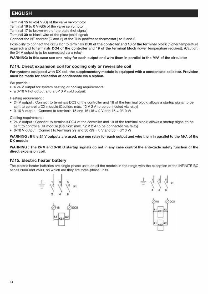
IV.15. Electric heater batteryThe electric heater batteries are single-phase units on all the models in the range with the exception of the INFINITE BCseries 2000 and 2500, on which are they are three-phase units.
ENGLISH
65
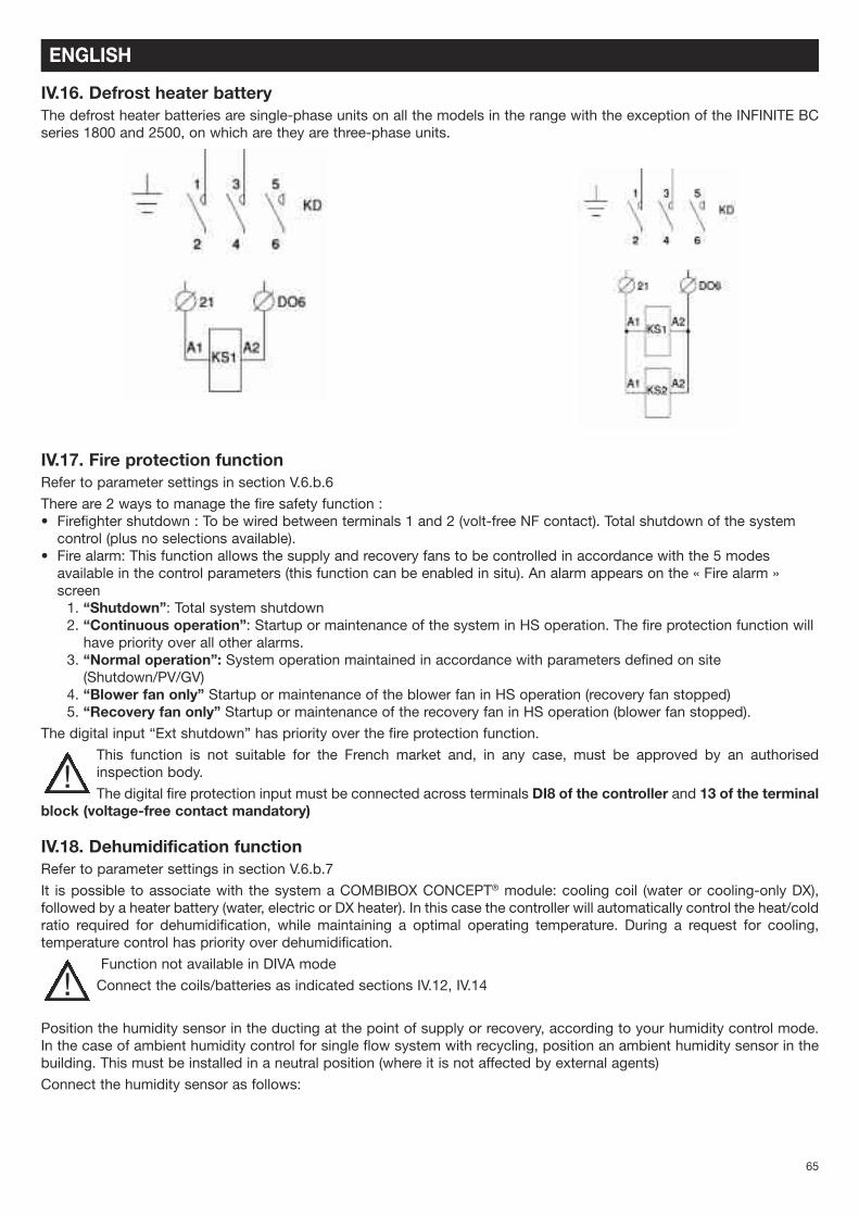
IV.16. Defrost heater batteryThe defrost heater batteries are single-phase units on all the models in the range with the exception of the INFINITE BCseries 1800 and 2500, on which are they are three-phase units.
IV.17. Fire protection functionRefer to parameter settings in section V.6.b.6
There are 2 ways to manage the fire safety function :• Firefighter shutdown : To be wired between terminals 1 and 2 (volt-free NF contact). Total shutdown of the systemcontrol (plus no selections available).
• Fire alarm: This function allows the supply and recovery fans to be controlled in accordance with the 5 modesavailable in the control parameters (this function can be enabled in situ). An alarm appears on the « Fire alarm »screen1. “Shutdown”: Total system shutdown2. “Continuous operation”: Startup or maintenance of the system in HS operation. The fire protection function willhave priority over all other alarms.
3. “Normal operation”: System operation maintained in accordance with parameters defined on site(Shutdown/PV/GV)
4. “Blower fan only” Startup or maintenance of the blower fan in HS operation (recovery fan stopped)5. “Recovery fan only” Startup or maintenance of the recovery fan in HS operation (blower fan stopped).
The digital input “Ext shutdown” has priority over the fire protection function.
This function is not suitable for the French market and, in any case, must be approved by an authorisedinspection body.
The digital fire protection input must be connected across terminals DI8 of the controller and 13 of the terminalblock (voltage-free contact mandatory)
IV.18. Dehumidification functionRefer to parameter settings in section V.6.b.7
It is possible to associate with the system a COMBIBOX CONCEPT® module: cooling coil (water or cooling-only DX),followed by a heater battery (water, electric or DX heater). In this case the controller will automatically control the heat/coldratio required for dehumidification, while maintaining a optimal operating temperature. During a request for cooling,temperature control has priority over dehumidification.
Function not available in DIVA mode
Connect the coils/batteries as indicated sections IV.12, IV.14
Position the humidity sensor in the ducting at the point of supply or recovery, according to your humidity control mode.In the case of ambient humidity control for single flow system with recycling, position an ambient humidity sensor in thebuilding. This must be installed in a neutral position (where it is not affected by external agents)
Connect the humidity sensor as follows:
ENGLISH
!
!
66
IV.19. MODBUS/WEB/BACNET connection(refer to parameter settings in section V.6.b)MODBUS RS485 : Use a shielded cable with twin twisted pairs, such as Belden 8723 or equivalent, to connect the BMSto the controller (connect to port 1 (BANE)/ connect shielding to N and do not connect E)
BACS TCP/IP type BACNET : connect to the TCP/IP portWEB : connect to the TCP/IP port
IV.20. Repeater connection(refer to parameter settings in section V.6.b.2)A repeater must be used when you connect:• More than one control panel to the same screen (maximum 6)• A remote control at a distance of more than 100m
In this case the remote control may be positioned at a maximum distance of 1 km. Connect the repeater and the controllerusing a shielded cable with twin twisted pairs, such as Belden 8723 or equivalent. Connect a single-phase 230 V powersupply.
Connect the wires to port 1 as follows :• B of the repeater to terminal B of the control panel (cable with shielded wire as shown in the diagram below)• A of the repeater to terminal A of the control panel (cable with shielded wire as shown in the diagram below)• N of the repeater to terminal N of the control panel (cable with shielded wire as shown in the diagram below)
Single-phase 230 V power supply to provided to the repeater.
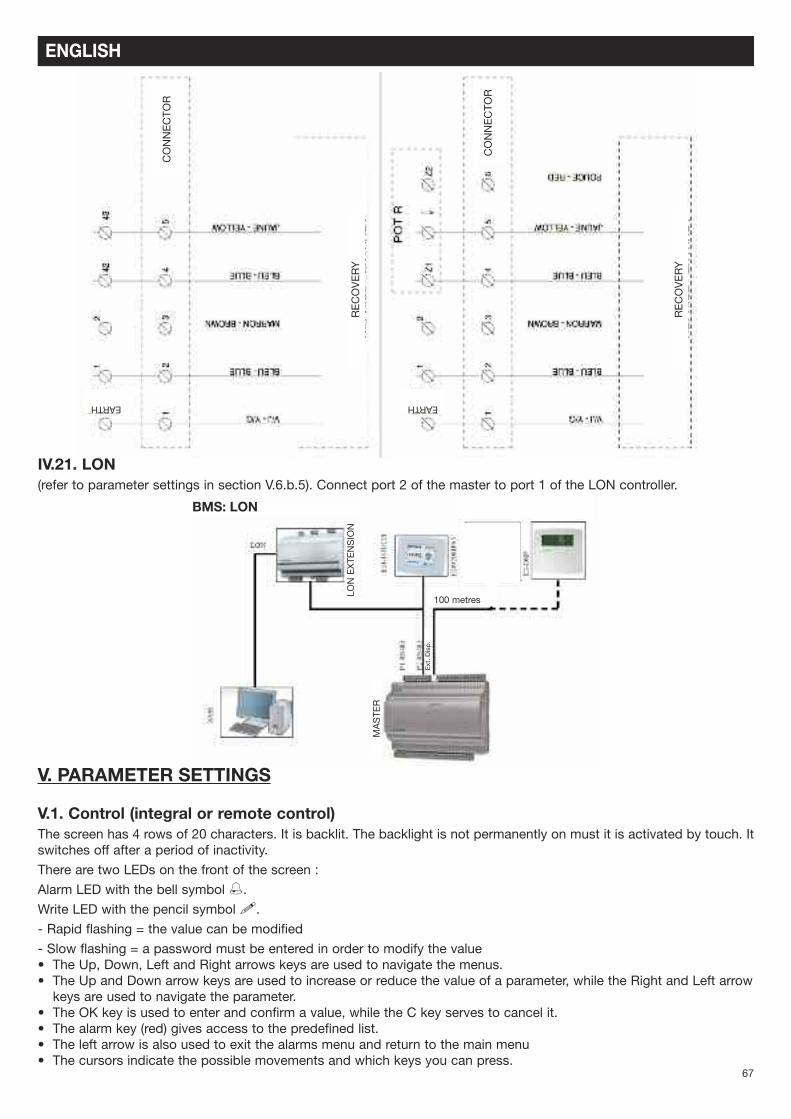
IV.21. LON(refer to parameter settings in section V.6.b.5). Connect port 2 of the master to port 1 of the LON controller.
V. PARAMETER SETTINGS
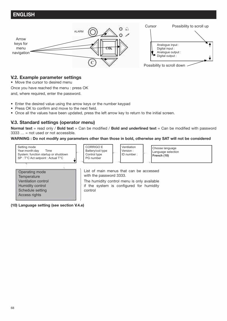
V.1. Control (integral or remote control)The screen has 4 rows of 20 characters. It is backlit. The backlight is not permanently on must it is activated by touch. Itswitches off after a period of inactivity.
There are two LEDs on the front of the screen :
Alarm LED with the bell symbol %.
Write LED with the pencil symbol !.
- Rapid flashing = the value can be modified
- Slow flashing = a password must be entered in order to modify the value• The Up, Down, Left and Right arrows keys are used to navigate the menus.• The Up and Down arrow keys are used to increase or reduce the value of a parameter, while the Right and Left arrowkeys are used to navigate the parameter.
• The OK key is used to enter and confirm a value, while the C key serves to cancel it.• The alarm key (red) gives access to the predefined list.• The left arrow is also used to exit the alarms menu and return to the main menu• The cursors indicate the possible movements and which keys you can press.
ENGLISH
CONNECTOR
CONNECTOR
RECOVERY
RECOVERY
EARTH EARTH
BMS: LON
100 metres
MASTER
Ext. Disp.
LON EXTENSION
68
V.2. Example parameter settings• Move the cursor to desired menu
Once you have reached the menu : press OK
and, where required, enter the password.
• Enter the desired value using the arrow keys or the number keypad• Press OK to confirm and move to the next field.• Once all the values have been updated, press the left arrow key to return to the initial screen.
V.3. Standard settings (operator menu)Normal text = read only / Bold text = Can be modified / Bold and underlined text = Can be modified with password3333 … = not used or not accessible.
WARNING : Do not modify any parameters other than those in bold, otherwise any SAT will not be considered
Setting modeYear:month:day TimeSystem: function startup or shutdownSP : T°C Act setpoint : Actual T°C
Choose languageLanguage selectionFrench (10)
CORRIGO EBattery/coil typeControl typePG number
VentilationVersion :ID number :
List of main menus that can be accessedwith the password 3333.
The humidity control menu is only availableif the system is configured for humiditycontrol
Operating modeTemperatureVentilation controlHumidity controlSchedule setting Access rights
ENGLISH
69
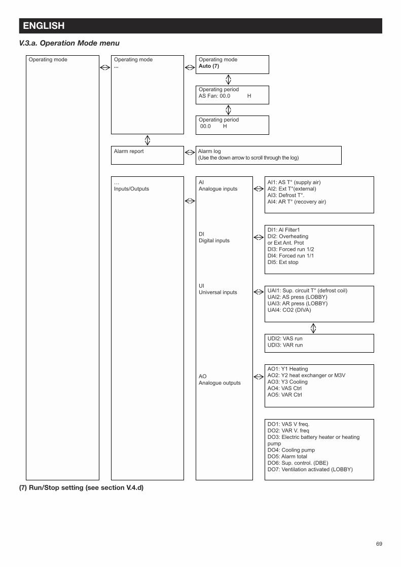
V.3.a. Operation Mode menu
ENGLISH
Operating mode Operating mode...
Alarm report Alarm log(Use the down arrow to scroll through the log)
…Inputs/Outputs
AIAnalogue inputs
DIDigital inputs
UIUniversal inputs
AOAnalogue outputs
AI1: AS T° (supply air)AI2: Ext T°(external)AI3: Defrost T°.AI4: AR T° (recovery air)
DI1: Al Filter1DI2: Overheatingor Ext Ant. ProtDI3: Forced run 1/2DI4: Forced run 1/1DI5: Ext stop
UAI1: Sup. circuit T° (defrost coil)UAI2: AS press (LOBBY)UAI3: AR press (LOBBY)UAI4: CO2 (DIVA)
UDI2: VAS runUDI3: VAR run
AO1: Y1 HeatingAO2: Y2 heat exchanger or M3VAO3: Y3 CoolingAO4: VAS CtrlAO5: VAR Ctrl
DO1: VAS V freq.DO2: VAR V. freqDO3: Electric battery heater or heatingpumpDO4: Cooling pumpDO5: Alarm totalDO6: Sup. control. (DBE)DO7: Ventilation activated (LOBBY)
Operating modeAuto (7)
Operating periodAS Fan: 00.0 H
Operating period00.0 H
(7) Run/Stop setting (see section V.4.d)
70
V.3.b. Temperature control menu
ENGLISH
Temperature control
Ventilation control
Recovery temperatureActual :Sepoint : 21°C (8)
Frequency control (ECO or DIVA)AS manual vent.Output: 70 (5)
%or
VAS pressure control(LOBBY)Actual : 183Pa (example)Reference : 180 Pa(5)
Frequency controlAS manual vent.Output 1/1 70% (5)Output 1/2 50% (5)
Frequency controlAS manual vent.Output 1/1 180Pa (5)Output 1/2 180Pa (5)
Frequency controlAS manual vent.Output 1/1 70% (5)Output 1/2 50% (5)
Frequency controlAS manual vent.Output 1/1 180Pa (5)Output 1/2 180Pa (5)
Frequency control(ECO or DIVA)AS manual vent.Output: 70 (5)
%or
VAS pressure control(LOBBY)Actual : 183Pa (example)Reference : 180 Pa(5)
Time : 15:54 (1)Date : 2011-01-25 (1)Day : Tuesday (1)
(8) Setting the setpoint temperature (see section V.4.c)
V.3.c. Ventilation control menu
(5) Speed, pressure, flow rate setting (see section V.4.b)
71
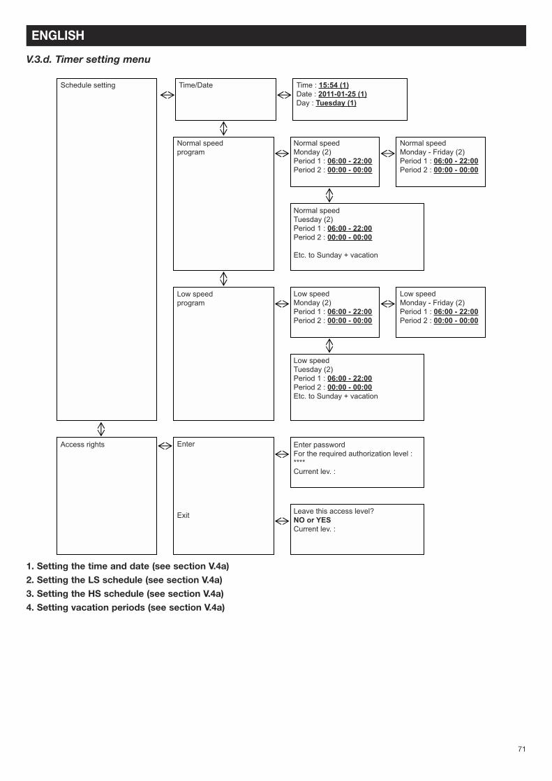
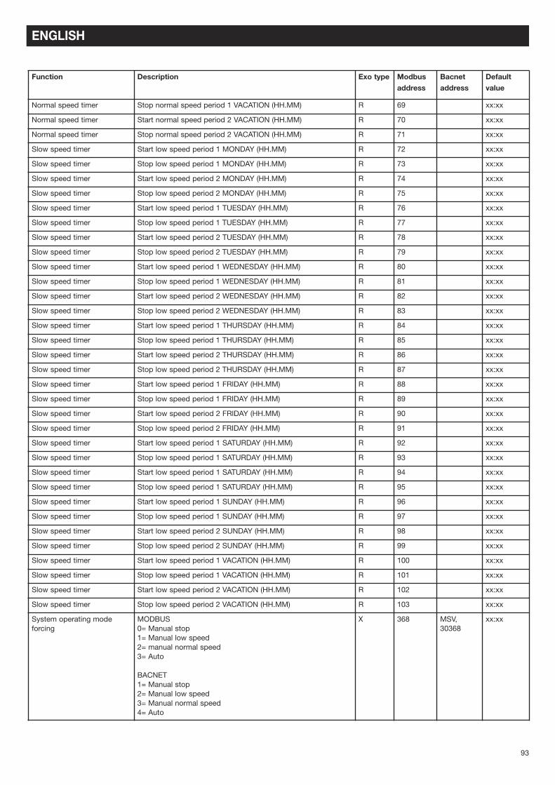
V.3.d. Timer setting menu
ENGLISH
1. Setting the time and date (see section V.4a)2. Setting the LS schedule (see section V.4a)3. Setting the HS schedule (see section V.4a)4. Setting vacation periods (see section V.4a)
V.4. Modification of operator parameters (password 3333 required)
V.4.a. Setting different time and date clocks
V.4.a.1. Date and time o the CORRIGO controller[(1) section V.3.d]Access : Timer/Time Date Setting
The date and time of the controller are pre-set in the CORRIGO. The changeover between the Summer and Winterschedules is managed automatically.
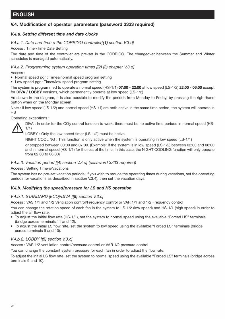
V.4.a.2. Programming system operation times [(2) (3) chapter V.3.d]Access :• Normal speed pgr : Times/normal speed program setting• Low speed pgr : Times/low speed program setting
The system is programmed to operate a normal speed (HS-1/1) 07:00 - 22:00 at low speed (LS-1/2) 22:00 - 06:00 exceptfor DIVA / LOBBY versions, which permanently operate at low speed (LS-1/2)
As shown in the diagram, it is also possible to modify the periods from Monday to Friday, by pressing the right-handbutton when on the Monday screen
Note : if low speed (LS-1/2) and normal speed (HS1/1) are both active in the same time period, the system will operate inHS
Operating exceptions :
DIVA : In order for the CO2 control function to work, there must be no active time periods in normal speed (HS-1/1)
LOBBY : Only the low speed timer (LS-1/2) must be active.
NIGHT COOLING : This function is only active when the system is operating in low speed (LS-1/1)
or stopped between 00:00 and 07:00. (Example: If the system is in low speed (LS-1/2) between 02:00 and 06:00and in normal speed (HS-1/1) for the rest of the time. In this case, the NIGHT COOLING function will only operatefrom 02:00 to 06:00)
The system has no pre-set vacation periods. If you wish to reduce the operating times during vacations, set the operatingperiods for vacations as described in section V.3.4), then set the vacation days.
V.4.b. Modifying the speed/pressure for LS and HS operation
V.4.b.1. STANDARD (ECO)/DIVA [(5) section V.3.c]Access : VAS 1/1 and 1/2 Ventilation control/Frequency control or VAR 1/1 and 1/2 Frequency control
You can change the rotation speed of each fan in the system to LS-1/2 (low speed) and HS-1/1 (high speed) in order toadjust the air flow rate.• To adjust the initial flow rate (HS-1/1), set the system to normal speed using the available “Forced HS” terminals(bridge across terminals 11 and 12).
• To adjust the initial LS flow rate, set the system to low speed using the available “Forced LS” terminals (bridgeacross terminals 9 and 10).
V.4.b.2. LOBBY [(5) section V.3.c]Access : VAS 1/2 ventilation control/pressure control or VAR 1/2 pressure control
You can change the constant system pressure for each fan in order to adjust the flow rate.
To adjust the initial LS flow rate, set the system to normal speed using the available “Forced LS” terminals (bridge acrossterminals 9 and 10).
ENGLISH
!
73
V.4.c. Modifying the temperature setpoint[(8) section V.3.b]Access : Temperature control
The setting is based on the temperature of :• the supply with external compensation (standard setting). In other words, the setpoint for the temperature changesaccording to the external temperature. This rule is defined in order to comply with RT 2012
• Recovery.
V.4.d. Forced shutdown of control unit or forced LS or HS operation on the remote control[(7)section V.3.a]Access : Operating mode/Operating mode
It is possible to stop (7) (shut down) the system via the CORRIGO command or execute a forced LS (7) (manual speed1/2) or HS (7) run (manual speed 1/1). As standard, the system operates in Automatic mode controlled by the timers(7) (Auto)
An alarm will be generated the moment the system is taken out of Auto mode. Note that the manual speed 1/1and manual speed 1/2 modes are used exclusively for activation and repairs. Any other setting will cause asystem malfunction.
V.4.e. Language selection[(10) section V.3]Access : Initial screen/Language selection
V.5. Intermediate settings (function level)In order to modify the setting type, the Night Cooling parameters and CO2 setpoint you need access to the configurationmenu at system level. This requires authorization to access the “Function” level. The procedure is as follows.
Enter the code 2222 using the arrow keys then press OK to confirm. Press the left arrow key twice to access the menus.If you make a mistake, press C twice and repeat the operation.
V.5.a. Configuration menu with function level access
1. Selection of the setting type (see section V.5.b.1)2. Modification of Night Cooling parameters (see section V.5.b.2)3. Modification of CO2 setpoints (DIVA and QUATTRO only) (see section V.5.b.3)
ENGLISH
!
Access rights Enter Enter the password 2222For the required authorization level :Current lev. : FUNCTION
V.5.b. Modification of function parameters (password 2222 required)
V.5.b.1. System control mode[(1)section V.5.a]Access : Configuration/Control function
The control type is pre-set in the CORRIGO to supply with external compensation It is also possible to switch to recoverycontrol mode.
(WARNING: if you wish to set the system according to an ambient temperature, select “Recover Ctrl” mode; anyother option will cause a system malfunction)
The ventilation speed is pre-set to 85%. This value can be modified. It is also possible to modify the temperature foractivation of Night Cooling (daytime external temperature/day, etc.) and deactivate it.
V.5.b.3. CO2 setpoint for DIVA QUATTRO option[(3)section V.5.a]Access : Configuration/Ctrl CO2/COV
The CO2 setpoints are pre-set: LS = 800 ppm HS = 1000 ppm. When the CO2 level reaches 1000 ppm, the system willincrease the operating speed proportionally up to its maximum speed.
V.6. Administrator settingsActivation of the communication, dehumidification and fire protection functions requires access to the configurationmenu at system level. Authorization for “Admin” level access is required. Proceed as follows:
Enter the password 1111 using the arrow keys and press OK to confirm. Press the left arrow key twice to access themenu. In case of error, press C twice and repeat the operation.
Access rights Enter Enter the password 1111For required authorization Current level: ADMIN
ENGLISH
75
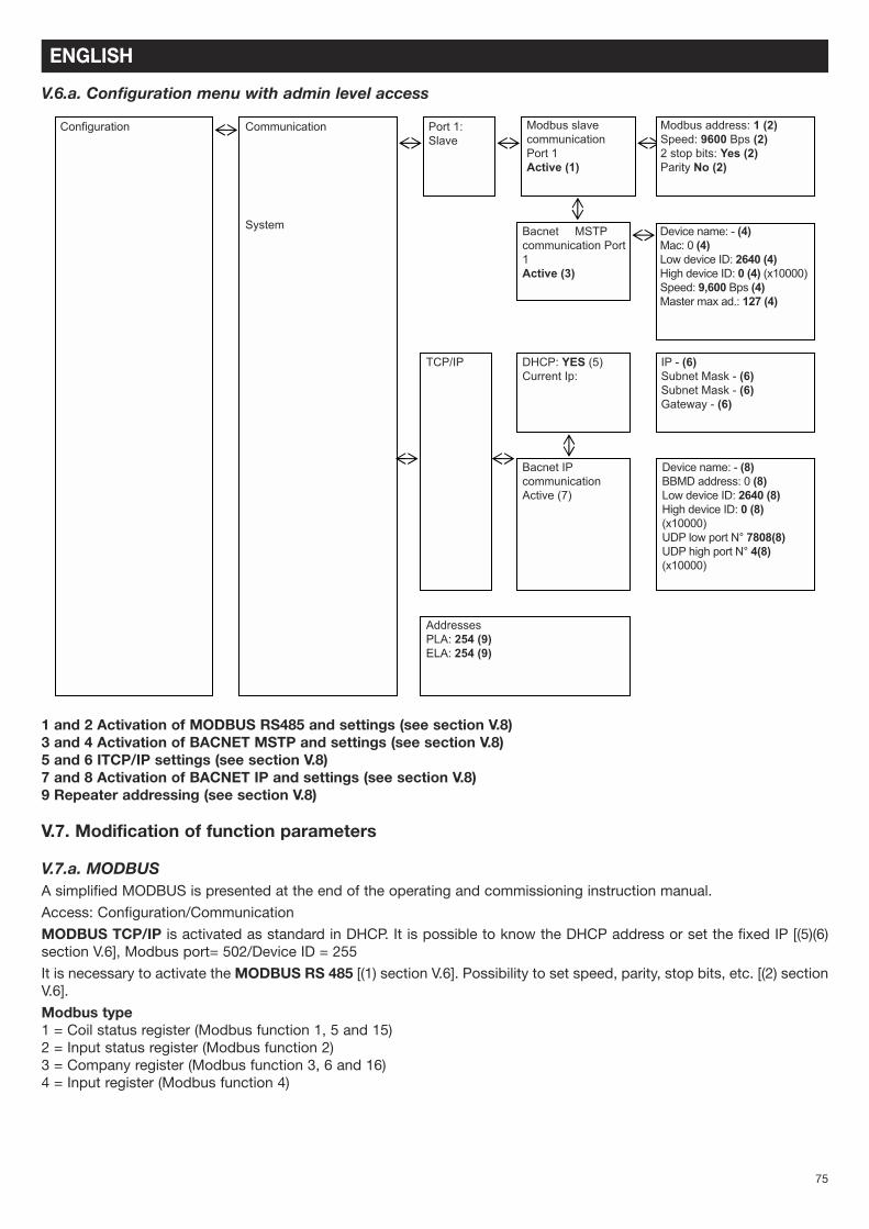
V.6.a. Configuration menu with admin level access
ENGLISH
Configuration Communication
System
Port 1:Slave
Modbus slavecommunication Port 1Active (1)
Bacnet MSTPcommunication Port1Active (3)
DHCP: YES (5)Current Ip:
Bacnet IPcommunicationActive (7)
Device name: - (8)BBMD address: 0 (8)Low device ID: 2640 (8)High device ID: 0 (8)(x10000)UDP low port N° 7808(8)UDP high port N° 4(8)(x10000)
1 and 2 Activation of MODBUS RS485 and settings (see section V.8)3 and 4 Activation of BACNET MSTP and settings (see section V.8)5 and 6 ITCP/IP settings (see section V.8)7 and 8 Activation of BACNET IP and settings (see section V.8)9 Repeater addressing (see section V.8)
V.7. Modification of function parameters
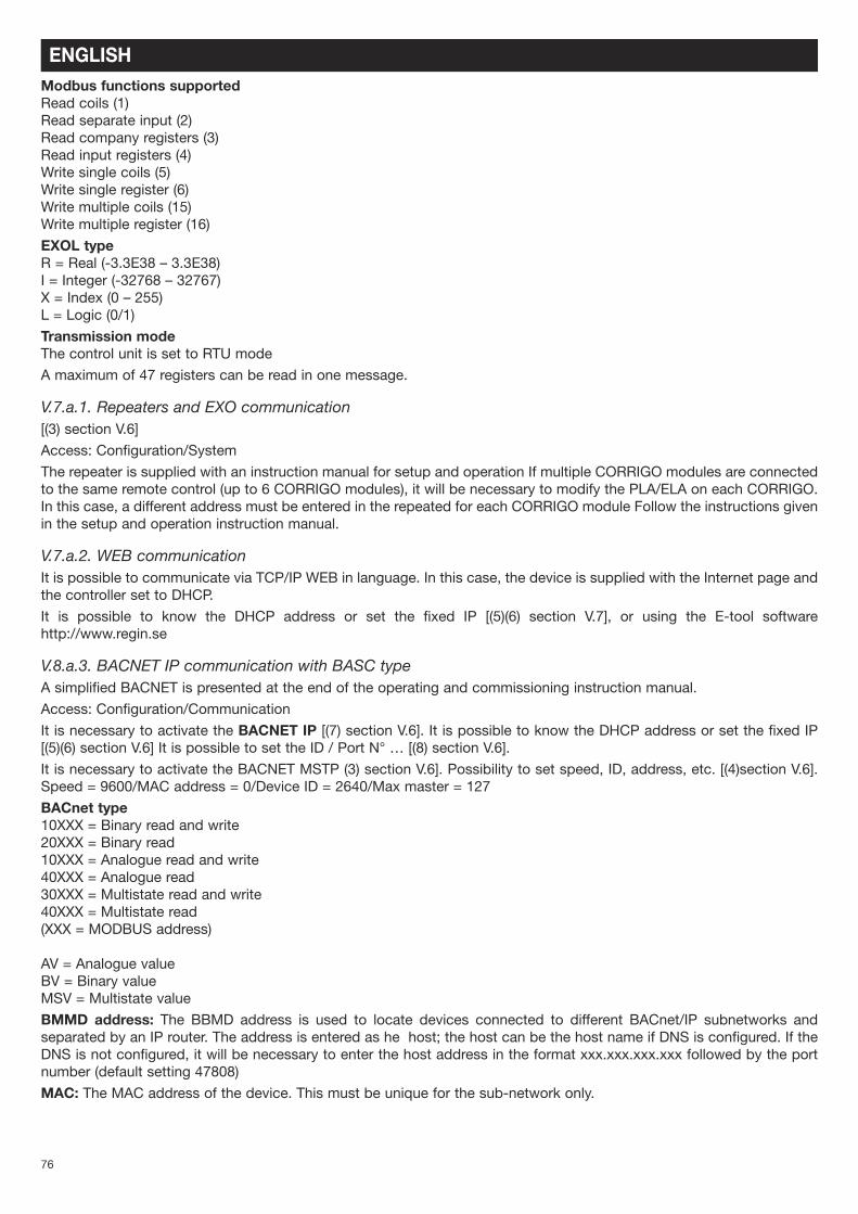
V.7.a. MODBUSA simplified MODBUS is presented at the end of the operating and commissioning instruction manual.
Access: Configuration/Communication
MODBUS TCP/IP is activated as standard in DHCP. It is possible to know the DHCP address or set the fixed IP [(5)(6)section V.6], Modbus port= 502/Device ID = 255
It is necessary to activate the MODBUS RS 485 [(1) section V.6]. Possibility to set speed, parity, stop bits, etc. [(2) sectionV.6].
Modbus type1 = Coil status register (Modbus function 1, 5 and 15)2 = Input status register (Modbus function 2)3 = Company register (Modbus function 3, 6 and 16)4 = Input register (Modbus function 4)
76
ENGLISHModbus functions supportedRead coils (1)Read separate input (2) Read company registers (3) Read input registers (4) Write single coils (5) Write single register (6) Write multiple coils (15)Write multiple register (16)
EXOL typeR = Real (-3.3E38 – 3.3E38) I = Integer (-32768 – 32767) X = Index (0 – 255)L = Logic (0/1)
Transmission modeThe control unit is set to RTU mode
A maximum of 47 registers can be read in one message.
V.7.a.1. Repeaters and EXO communication[(3) section V.6]
Access: Configuration/System
The repeater is supplied with an instruction manual for setup and operation If multiple CORRIGO modules are connectedto the same remote control (up to 6 CORRIGO modules), it will be necessary to modify the PLA/ELA on each CORRIGO.In this case, a different address must be entered in the repeated for each CORRIGO module Follow the instructions givenin the setup and operation instruction manual.
V.7.a.2. WEB communicationIt is possible to communicate via TCP/IP WEB in language. In this case, the device is supplied with the Internet page andthe controller set to DHCP.
It is possible to know the DHCP address or set the fixed IP [(5)(6) section V.7], or using the E-tool softwarehttp://www.regin.se
V.8.a.3. BACNET IP communication with BASC typeA simplified BACNET is presented at the end of the operating and commissioning instruction manual.
Access: Configuration/Communication
It is necessary to activate the BACNET IP [(7) section V.6]. It is possible to know the DHCP address or set the fixed IP[(5)(6) section V.6] It is possible to set the ID / Port N° … [(8) section V.6].
It is necessary to activate the BACNET MSTP (3) section V.6]. Possibility to set speed, ID, address, etc. [(4)section V.6].Speed = 9600/MAC address = 0/Device ID = 2640/Max master = 127
BACnet type10XXX = Binary read and write20XXX = Binary read10XXX = Analogue read and write40XXX = Analogue read30XXX = Multistate read and write40XXX = Multistate read(XXX = MODBUS address)
AV = Analogue valueBV = Binary value MSV = Multistate value
BMMD address: The BBMD address is used to locate devices connected to different BACnet/IP subnetworks andseparated by an IP router. The address is entered as he host; the host can be the host name if DNS is configured. If theDNS is not configured, it will be necessary to enter the host address in the format xxx.xxx.xxx.xxx followed by the portnumber (default setting 47808)
MAC: The MAC address of the device. This must be unique for the sub-network only.
77
ENGLISH
Device ID: The ID of a device, used to identify it on the BACnet. This number must not be duplicated anywhere else onthe BACnet and therefore must be unique. To set an ID value of 34600, the low number must be set to 4600 and the highnumber to 3
For more information, refer to the CORRIGO images at http://www.regin.se
V.8.a.4. LON communication (if CORRIGO with LON option)Set the LON function as follows:
In the menu Configuration/Communication/Function port 2 = activate port 2 in the extension unit.
Go to the right and activate the extension unit. 1 in CORRIGO E28 LON
The button for the PIN service is located on the rear of the controller.
The communication table is located at http://www.regincontrols.com
V.8.a.5. Activation of fire protection functionSetting the input parametersAccess: Configuration/Input Output/DI/ DI8Declare input DI8 as “Fire Al” “NO”Definition of function parametersAccess: Configuration/Fire protection functionSelect the required operating mode to be activated when the fire protection function is activated“Shutdown”: Total shutdown of the unit“Continuous operation” Startup or maintenance of unit operation in HS mode. The fire protection function will have priority over all other alarms.“Normal operation”: the unit will continue to operate within the parameters selected on site (stop/LS/HS)“Exhaust fan only”: Start or maintain exhaust fan operation in HS mode (the recovery fan is stopped)“Recovery fan only”: Start or maintain recovery fan operation in HS mode (the exhaust fan is stopped)
Enter alarm number “10”, go to the right and enter in priority “C alarm C” “Active”
V.8.a.6. Activation of the dehumidification functionInput settingsAccess: Configuration/Input Output/UI/ UI4Declare input UI4 “Ambient humidity”
Function settingAccess: Configuration/Humidity control“Select dehumidification”
Reference value settingAccess: Humidity controlEnter the desired setpoint
ENGLISH
Description Cause
The CORRIGO screen does notswitch on
- The system is not receiving sufficient power (P/B LED of the CORRIGO off)- To illuminate the screen, press a key (backlighting).- The control fuse is out of service
The fan/s does/do not work - The timers are on 0- No external run command- External shutdown- Alarm active
The remote control does not workor sends incorrect values
Remote control at distance > 100 mRepeater not connected correctly.
VI. PROBLEM SOLVING
VI.1. Different types of faultThe EASY setting on VORT NRG EC / EC H systems is equipped with alarms. When the red LED flashes, press the alarmbutton (red) to view the fault.
The fault will either be class A or class C (see detailed information below)
Fault type :
A : The fault causes the ventilation system to shut down. The device will not function until the problem has been resolvedand the fault eliminated.
C : The fault does not cause the ventilation system to shut down and the alarm will be reset automatically once theproblem has been resolved. To cancel a fault, press the alarm key (red), then “cancel” and “log” the fault using the arrowkeys and press OK. Warning: do not “lock”
78
ENGLISH
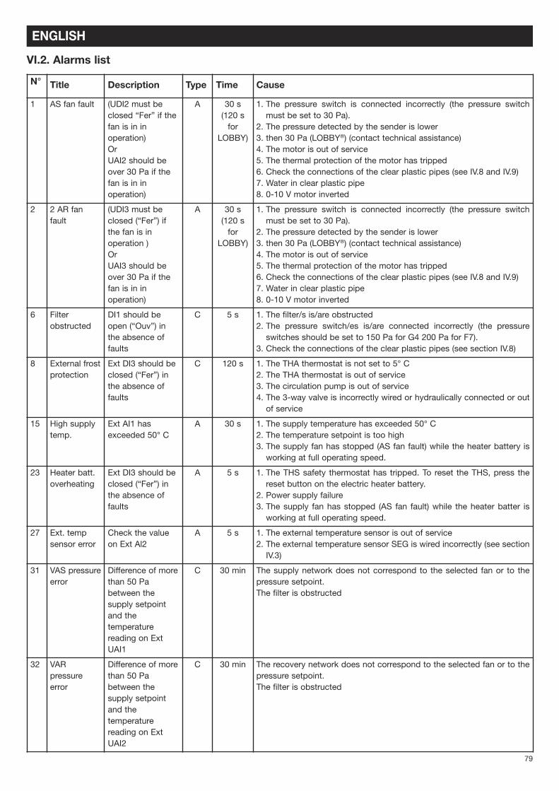
N° Title Description Type Time Cause
1 AS fan fault (UDI2 must beclosed “Fer” if thefan is in inoperation)OrUAI2 should beover 30 Pa if thefan is in inoperation)
A 30 s(120 sfor
LOBBY)
1. The pressure switch is connected incorrectly (the pressure switchmust be set to 30 Pa).
2. The pressure detected by the sender is lower3. then 30 Pa (LOBBY®) (contact technical assistance)4. The motor is out of service5. The thermal protection of the motor has tripped6. Check the connections of the clear plastic pipes (see IV.8 and IV.9)7. Water in clear plastic pipe8. 0-10 V motor inverted
2 2 AR fanfault
(UDI3 must beclosed (“Fer”) ifthe fan is inoperation )OrUAI3 should beover 30 Pa if thefan is in inoperation)
A 30 s(120 sfor
LOBBY)
1. The pressure switch is connected incorrectly (the pressure switchmust be set to 30 Pa).
2. The pressure detected by the sender is lower3. then 30 Pa (LOBBY®) (contact technical assistance)4. The motor is out of service5. The thermal protection of the motor has tripped6. Check the connections of the clear plastic pipes (see IV.8 and IV.9)7. Water in clear plastic pipe8. 0-10 V motor inverted
6 Filterobstructed
DI1 should beopen (“Ouv”) inthe absence offaults
C 5 s 1. The filter/s is/are obstructed2. The pressure switch/es is/are connected incorrectly (the pressureswitches should be set to 150 Pa for G4 200 Pa for F7).
3. Check the connections of the clear plastic pipes (see section IV.8)
8 External frostprotection
Ext DI3 should beclosed (“Fer”) inthe absence offaults
C 120 s 1. The THA thermostat is not set to 5° C2. The THA thermostat is out of service3. The circulation pump is out of service4. The 3-way valve is incorrectly wired or hydraulically connected or outof service
15 High supplytemp.
Ext AI1 hasexceeded 50° C
A 30 s 1. The supply temperature has exceeded 50° C2. The temperature setpoint is too high3. The supply fan has stopped (AS fan fault) while the heater battery isworking at full operating speed.
23 Heater batt.overheating
Ext DI3 should beclosed (“Fer”) inthe absence offaults
A 5 s 1. The THS safety thermostat has tripped. To reset the THS, press thereset button on the electric heater battery.
2. Power supply failure3. The supply fan has stopped (AS fan fault) while the heater batter isworking at full operating speed.
27 Ext. tempsensor error
Check the valueon Ext Al2
A 5 s 1. The external temperature sensor is out of service2. The external temperature sensor SEG is wired incorrectly (see sectionIV.3)
31 VAS pressureerror
Difference of morethan 50 Pabetween thesupply setpointand thetemperaturereading on ExtUAI1
C 30 min The supply network does not correspond to the selected fan or to thepressure setpoint.The filter is obstructed
32 VARpressureerror
Difference of morethan 50 Pabetween thesupply setpointand thetemperaturereading on ExtUAI2
C 30 min The recovery network does not correspond to the selected fan or to thepressure setpoint.The filter is obstructed
VI.2. Alarms list
79
ENGLISH
N° Title Description Type Time Cause
35 Manual Operation inmanual mode
C 5 s Fault for information only (the system has switched to shutdown in PVor to PG directly on the display (see (7) section V.3.a)
from36to44
...in manualmode
Some functionshave switched tomanual mode.
C 5 s In the Manual/Auto menu all options should be set to Auto.
48 Low charge Internal batteryerror
A 5 s The internal battery of the CORRIGO is faulty.Change the battery so as not lose the program.See section VII.2
49 AS tempsensor error
Check value onExt Al1
A 5 s The SSG external temperature sensor is out of serviceThe SSG external temperature sensor is wired incorrectly (see section V.3.a)
50 AR tempsensor error
Check value onExt Al3
A 5 s The SRG external temperature sensor is out of serviceThe SRG external temperature sensor is wired incorrectly (see section V.3.a)
55 VAS pressuresensor error
Check value onExt UAI1
A 5 s The 0-10 V signal is invertedThe fresh air pressure sender is short-circuited
56 VAR pressuresensor error
Check value onExt UAI2
A 5 s The 0-10 V signal is invertedThe recovery air pressure sender is short-circuited
59 CO2 sensorerror
Check value onExt AI 4
A 5 s The 0-10 V signal is invertedThe CO2 pressure sender is short-circuited
85 ...in manualmode
Some functionshave switched tomanual mode.
A 5 s In the Manual/Auto menu all options should be set to Auto.
86 Carry out theservicingoperation
Periodicinspection
C 5 s See section VI.3
87 ...in manualmode
Some functionshave switched tomanual mode.
C 5 s In the Manual/Auto menu all options should be set to Auto.
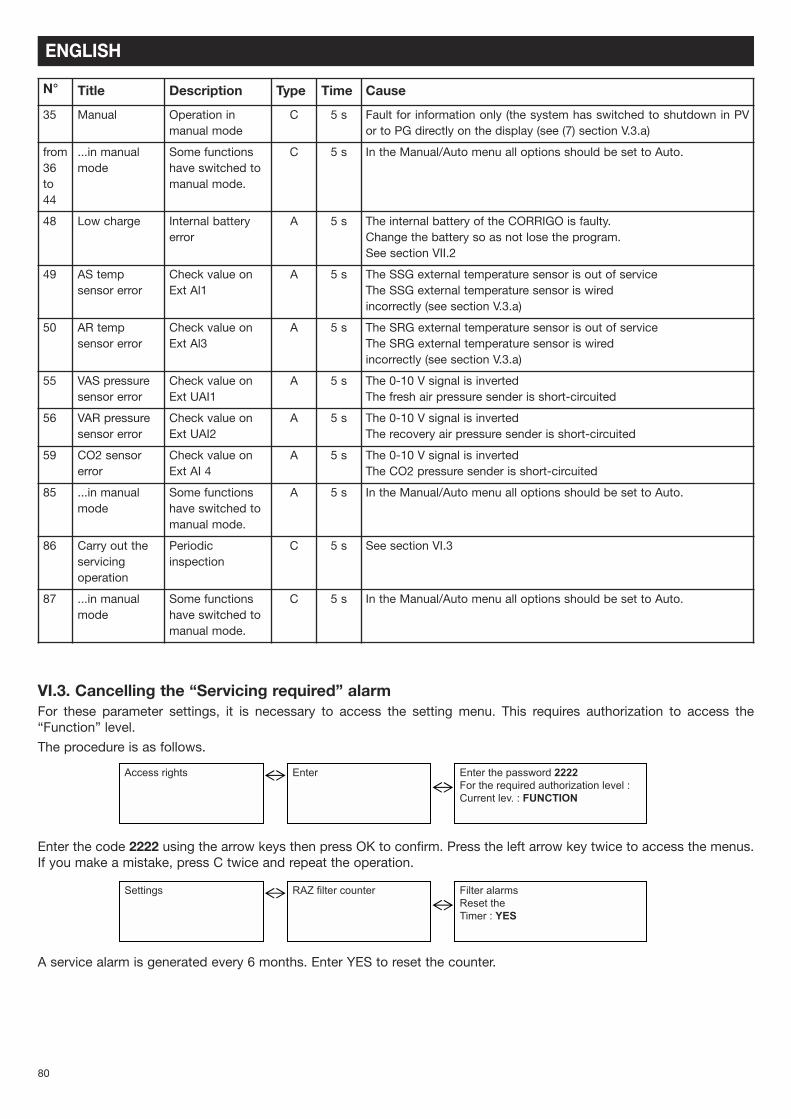
VI.3. Cancelling the “Servicing required” alarmFor these parameter settings, it is necessary to access the setting menu. This requires authorization to access the“Function” level.
The procedure is as follows.
Enter the code 2222 using the arrow keys then press OK to confirm. Press the left arrow key twice to access the menus.If you make a mistake, press C twice and repeat the operation.
A service alarm is generated every 6 months. Enter YES to reset the counter.
Access rights Enter Enter the password 2222For the required authorization level :Current lev. : FUNCTION
Settings RAZ filter counter Filter alarmsReset theTimer : YES
80
VII. MAINTENANCE
VII.1. Essential maintenanceSystem exteriorCheck the ducts, flexible hoses and dampers and renew if necessary. Check that all the components connected to thesystem are positioned in such a way that vibration is not transmitted to external elements.
System and controls Every year check the electrical connections.
FiltrationDo not damage the filter element
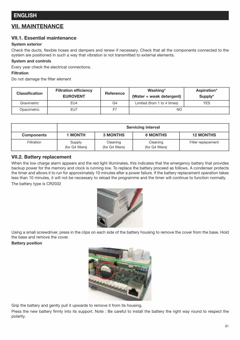
VII.2. Battery replacementWhen the low charge alarm appears and the red light illuminates, this indicates that the emergency battery that providesbackup power for the memory and clock is running low. To replace the battery proceed as follows. A condenser protectsthe timer and allows it to run for approximately 10 minutes after a power failure. If the battery replacement operation takesless than 10 minutes, it will not be necessary to reload the programme and the timer will continue to function normally.
The battery type is CR2032
Using a small screwdriver, press in the clips on each side of the battery housing to remove the cover from the base. Holdthe base and remove the cover.
Battery position
Grip the battery and gently pull it upwards to remove it from its housing.
Press the new battery firmly into its support. Note : Be careful to install the battery the right way round to respect thepolarity.
ENGLISH
ClassificationFiltration efficiency
EUROVENTReference
Washing*(Water + weak detergent)
Aspiration*Supply*
Gravimetric EU4 G4 Limited (from 1 to 4 times) YES
Opacimetric EU7 F7 NO
Servicing interval
Components 1 MONTH 3 MONTHS 6 MONTHS 12 MONTHS
Filtration Supply(for G4 filters)
Cleaning(for G4 filters)
Cleaning(for G4 filters)
Filter replacement
81
VIII. APPENDICES
VIII.1. Control diagram
ENGLISH
This docum
ent is our property and may not be reproduced without prior authorisation.
FUSE TERMINAL
PORT 1
RS485
PORT 2
RS485
Ext. disp.
Modular
conn.
4P4C
82
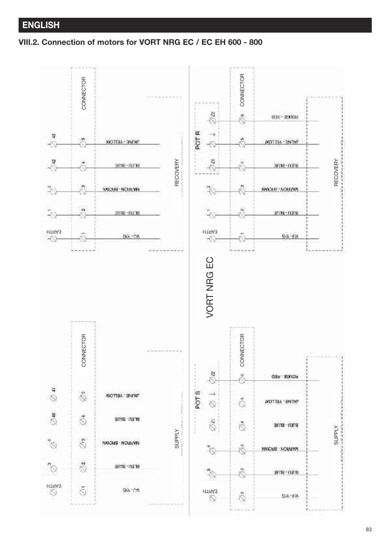
VIII.2. Connection of motors for VORT NRG EC / EC EH 600 - 800
ENGLISH
VORT NRG EC
CONNECTOR
CONNECTOR
CONNECTOR
CONNECTOR
RECOVERY
RECOVERY
SUPPLY
SUPPLY
EARTH EARTH
EARTHEARTH
83
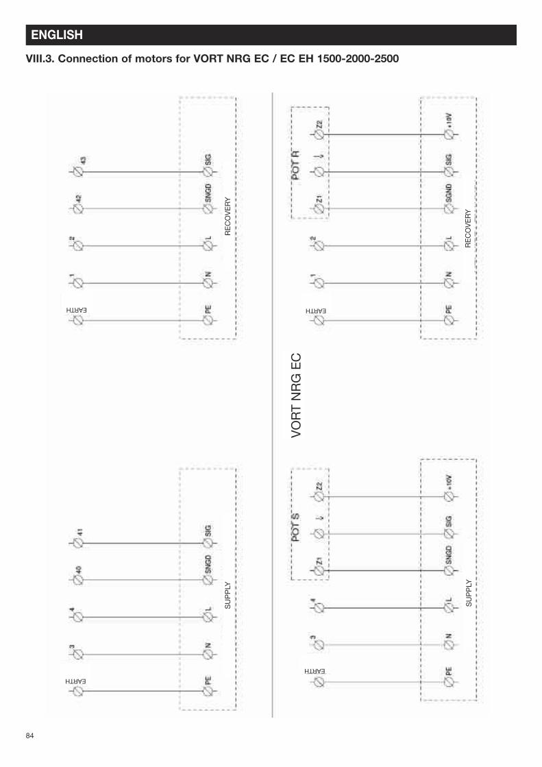
VIII.3. Connection of motors for VORT NRG EC / EC EH 1500-2000-2500
ENGLISH
VORT NRG EC
RECOVERY
RECOVERY
SUPPLY
SUPPLY
EARTH EARTH
EARTH
EARTH
84
VIII.4. Graphs
ENGLISH
NEOTIME® 600
0
200
400
600
800
1000
100 200 300 400 500 600
Débit (m3/h)
Pres
sion
sta
tique
(Pa)
100%
90%
80%
70%
60%
50%
40%
NEOTIME® 900
0
200
400
600
800
009008007006005004003002
Débit (m3/h)
Pres
sion
sta
tique
(Pa)
100%90%80%
70%
60%
50%
40%
NEOTIME® 1300
0
100
200
300
400
500
400 600 800 1000 1200 1400
Débit (m3/h)
Pres
sion
sta
tique
(Pa)
MAX = 90%
80%
70%
60%
60%
40%
Static Pressure (Pa)
Static Pressure (Pa)
Static Pressure (Pa)
Flow rate m3/h
Flow rate m3/h
Flow rate m3/h
85
VORT NRG EC / EC EH 600
VORT NRG EC / EC EH 800
VORT NRG EC / EC EH 1500
ENGLISH
NEOTIME® 1800
0
100
200
300
400
500
000200810061004100210001008006
Débit (m3/h)
Pres
sion
sta
tique
(Pa)
100%
90%
80%
70%
60%
50%
NEOTIME® 2500
0
100
200
300
400
500
0052052200020571005105210001
Débit (m3/h)
Pres
sion
sta
tique
(Pa)
100%
90%
80%
70%
60%
50%
Static Pressure (Pa)
Flow rate m3/h
Static Pressure (Pa)
Flow rate m3/h
86
VORT NRG EC / EC EH 1800
VORT NRG EC / EC EH 2500
VIII.5. MODBUS and BACNET table
VIII.5.a. MODBUS informationIntroductionCorrigo E ventilation is a pre-programmed application for control of an air handling unit (CTA). The Corrigo E controllercan either be used as a stand-alone unit or integrated in an existing EXO project. In both cases it is configured via thedisplay or using the configuration tool E tool on a PC. This document describes all the signals that can be accessed viaEXOline or Modbus. This document does not describe how to create an EXO system.
Signal types All signals that are accessible from a SCADA system are described in this document. The signals that have a default valueare parameter settings that can be changed from SCADA. The signals without default values are actual values and cannotbe changed from SCADA.
EXOL typeEXOL type signals :R = Real number with decimal point (Real) (-3.3E3S -3.3E38)I = Whole number (Integer) (-32768 -32767)X = Index (0 - 255)L = Boolean (Logic) (0/1)
Modbus typeModbus type signals :1 = Coil Status Register (Modbus function = 1.5 and 15)2 = Coil Status Register (Modbus function = 2 and 15)3 = Holding Register (Modbus function = 3. 6 e 16)4 = Input Register (Modbus function = 4)
Max. 47 registers A maximum of 47 registers can be read in one message.
Communication limitsThe Modbus master must wait for a minimum of 3.5 charactertimes (4 ms at 9600 bps) between two messages. Whenthe Modbus master communicates with more than one Corrigo E controller on the same communication line (RS485), theModbus master must wait for a minimum of 14 charactertimes (16 ms at 9600 bps) between the answer and the firstquestion for the next controller.
The Corrigo E controller has a limit of 10 fast communications every 30 seconds, while other communications will have aanswering delay of approximately 1 second.
Scale factor ModbusAll real signals (decimal) have scale factor 10, except the time settings signals that have scale factor 100 and Air flowsignals that have scale factor 1 for Modbus communication. Integer, Index and Logic signals have scale factor 1.
Modbus activationThe Corrigo controller uses the same port for both Modbus communication and EXOline communication. If you try tocommunicate with a Modbus-activated unit using E tool or another type of EXOline communication, the input port will willautomatically adapt itself after approx. one second. The port will remain in EXO-mode until 10 seconds of communicationinactivity have passed after which it will revert to Modbus mode.
ENGLISH
87
Modbus ConnectionThe Modbus protocol consists of several layers (OSI model). The bottom layer is the physical layer, and is comprised ofa number of wires and signal levels. The next layer describes the communication digits (number of data bits, stop-bits,parity, etc). Next are the layers describing the specific functions of the Modbus protocol (number of digits per message,the meanings of different messages, etc).
For Modbus, the physical layer can be RS485, RS422 or RS232.
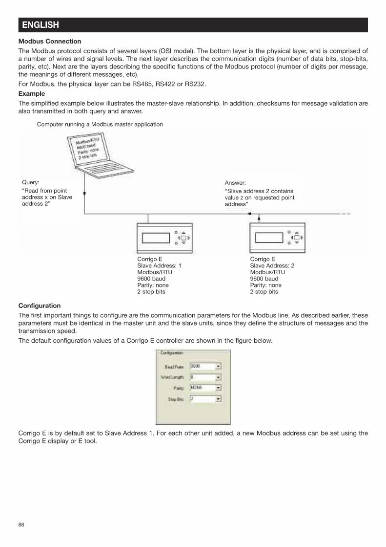
ExampleThe simplified example below illustrates the master-slave relationship. In addition, checksums for message validation arealso transmitted in both query and answer.
ConfigurationThe first important things to configure are the communication parameters for the Modbus line. As described earlier, theseparameters must be identical in the master unit and the slave units, since they define the structure of messages and thetransmission speed.
The default configuration values of a Corrigo E controller are shown in the figure below.
Corrigo E is by default set to Slave Address 1. For each other unit added, a new Modbus address can be set using theCorrigo E display or E tool.
Computer running a Modbus master application
Query:“Read from pointaddress x on Slaveaddress 2”
Answer:“Slave address 2 containsvalue z on requested pointaddress”
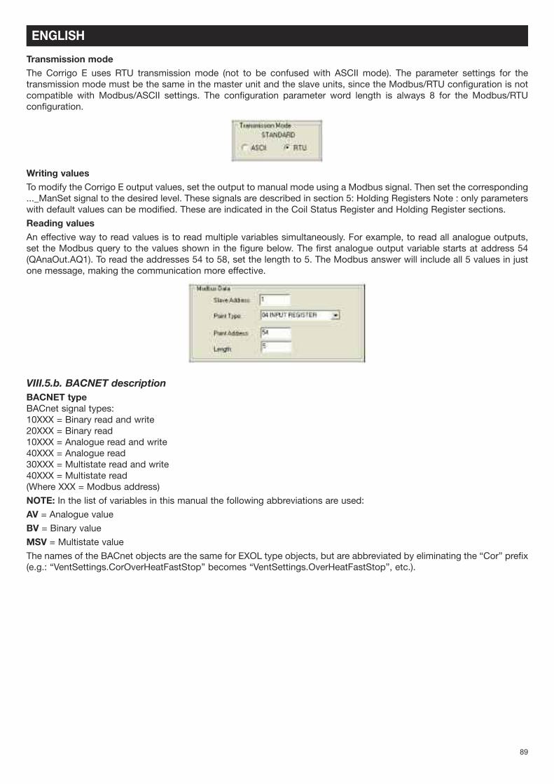
Transmission modeThe Corrigo E uses RTU transmission mode (not to be confused with ASCII mode). The parameter settings for thetransmission mode must be the same in the master unit and the slave units, since the Modbus/RTU configuration is notcompatible with Modbus/ASCII settings. The configuration parameter word length is always 8 for the Modbus/RTUconfiguration.
Writing valuesTo modify the Corrigo E output values, set the output to manual mode using a Modbus signal. Then set the corresponding..._ManSet signal to the desired level. These signals are described in section 5: Holding Registers Note : only parameterswith default values can be modified. These are indicated in the Coil Status Register and Holding Register sections.
Reading valuesAn effective way to read values is to read multiple variables simultaneously. For example, to read all analogue outputs,set the Modbus query to the values shown in the figure below. The first analogue output variable starts at address 54(QAnaOut.AQ1). To read the addresses 54 to 58, set the length to 5. The Modbus answer will include all 5 values in justone message, making the communication more effective.
VIII.5.b. BACNET descriptionBACNET typeBACnet signal types:10XXX = Binary read and write20XXX = Binary read10XXX = Analogue read and write40XXX = Analogue read30XXX = Multistate read and write40XXX = Multistate read(Where XXX = Modbus address)
NOTE: In the list of variables in this manual the following abbreviations are used:AV = Analogue valueBV = Binary valueMSV = Multistate valueThe names of the BACnet objects are the same for EXOL type objects, but are abbreviated by eliminating the “Cor” prefix(e.g.: “VentSettings.CorOverHeatFastStop” becomes “VentSettings.OverHeatFastStop”, etc.).
ENGLISH
89
ENGLISH
AddressingThe figure below illustrates how BACnet addressing is presented E tool.
BACnet/IP = Activation status of the BACnet/IP protocol.
Name of the BACnet device = the name of the device.
The ID of the device is divided into two parts: one low and one high. For example: If the high part of the ID is “1”, thedevice ID would be “00012640”.
Low ID of the BACnet device = the lower part of the device identification.
High ID of the BACnet device (x 10000) = the higher part of the device identification.
The port number is divided into two parts: on low and one high For example: In the illustration above, the port number is“47808”.
Low BACnet/IP FIDP port number = port number, low part.
High BACnet/IP FIDP port number (x 10000) = port number, high part. This is the designated port for communication.
BBMD address = Address of the BACnet transmission control device. This is used for internet communication betweendevices with BACnet.
90
VIII.5.c. TABLE
INPUT REGISTER
ENGLISH
Function Description Exo type Modbusaddress
Bacnetaddress
Defaultvalue
System status Modbus :0= stop1= startup2= low speed startup3= maximum speed startup4= normal speed startup5= in operation8= o CO2 operation9= Night cooling11= shutting down
BACNET :1= stop2= startup3= lo speed startup4= maximum speed startup5= normal speed startup6= in operation9= CO2 operation10= Night cooling12= shutting down
X 3 MSV,40003
External temperature R 1 AV,40001
Operating temperature of theblower fan
R 4 AV,40004
Operating temperature of therecovery fan
R 5 AV,40005
Supply temperature R 7 AV,40007
Extraction temperature R 9 AV,40009
Fresh air pressure LOBBY EC R 13 AV,40013
Recovery air pressure LOBBY EC R 14 AV,40014
CO2 DIVA R 17 AV,40017
Defrost temperature R 21 AV,40021
Humidity R 23 AV,40023
Defrost heater temperature R 25 AV,40025
Analogue output 0-10 V heating (WATER COIL) R 54
Analogue output 0-10 V Heat exchanger R 55
Analogue output 0-10 V Heat exchanger R 56
Analogue output 0-10 V Supply R 57
Analogue output 0-10V Recovery R 58
91
Function Description Exo type Modbus
address
Bacnet
address
Default
value
Supply setpoint Configured as constant supply R 1 AV,30001 18
Supply setpoint Configured as Ext.comp supply for ext T°C of –20° C R 10 25
Supply setpoint Configured as Ext.comp supply for ext T°C of –15° C R 11 24
Supply setpoint Configured as Ext.comp supply for ext T°C of –10° C R 12 23
Supply setpoint Configured as Ext.comp supply for ext T°C of –5° C R 13 23
Supply setpoint Configured as Ext.comp supply for ext T°C of –0° C R 14 22
Supply setpoint Configured as Ext.comp supply for ext T°C of +5° C R 15 20
Supply setpoint Configured as Ext.comp supply for ext T°C of +10° C R 16 18
Supply setpoint Configured as Ext.comp supply for ext T°C of +15° C R 17 18
Recovery setpoint Configured for recovery control R 18 AV,30018 21
HS supply speed setpoint In % for ECO and DIVA models R 424 70
LS supply speed setpoint In % for ECO and DIVA models R 425 50
HS recovery speed setpoint In % for ECO and DIVA models R 426 70
LS recovery speed setpoint In % for ECO and DIVA models R 427 50
Supply pressure setpoint In Pa for LOBBY model R 25 AV,30025 150
Recovery pressure setpoint In Pa for LOBBY model R 27 AV,30027 150
Normal speed timer Start normal speed period 1 MONDAY (HH.MM) R 40 xx:xx
Normal speed timer Stop normal speed period 1 MONDAY (HH.MM) R 41 xx:xx
Normal speed timer Start normal speed period 2 MONDAY (HH.MM) R 42 xx:xx
Normal speed timer Stop normal speed period 2 MONDAY (HH.MM) R 43 xx:xx
Normal speed timer Start normal speed period 1 TUESDAY (HH.MM) R 44 xx:xx
Normal speed timer Stop normal speed period 1 TUESDAY (HH.MM) R 45 xx:xx
Normal speed timer Start normal speed period 2 TUESDAY (HH.MM) R 46 xx:xx
Normal speed timer Stop normal speed period 2 TUESDAY (HH.MM) R 47 xx:xx
Normal speed timer Start normal speed period 1 WEDNESDAY (HH.MM) R 48 xx:xx
Normal speed timer Stop normal speed period 1 WEDNESDAY (HH.MM) R 49 xx:xx
Normal speed timer Start normal speed period 2 WEDNESDAY (HH.MM) R 50 xx:xx
Normal speed timer Stop normal speed period 2 WEDNESDAY (HH.MM) R 51 xx:xx
Normal speed timer Start normal speed period 1 THURSDAY (HH.MM) R 52 xx:xx
Normal speed timer Stop normal speed period 1 THURSDAY (HH.MM) R 53 xx:xx
Normal speed timer Start normal speed period 2 THURSDAY (HH.MM) R 54 xx:xx
Normal speed timer Stop normal speed period 2 THURSDAY (HH.MM) R 55 xx:xx
Normal speed timer Start normal speed period 1 FRIDAY (HH.MM) R 56 xx:xx
Normal speed timer Stop normal speed period 1 FRIDAY (HH.MM) R 57 xx:xx
Normal speed timer Start normal speed period 2 FRIDAY (HH.MM) R 58 xx:xx
Normal speed timer Stop normal speed period 2 FRIDAY (HH.MM) R 59 xx:xx
Normal speed timer Start normal speed period 1 SATURDAY (HH.MM) R 60 xx:xx
Normal speed timer Stop normal speed period 1 SATURDAY (HH.MM) R 61 xx:xx
Normal speed timer Start normal speed period 1 SATURDAY (HH.MM) R 62 xx:xx
Normal speed timer Stop normal speed period 1 SATURDAY (HH.MM) R 63 xx:xx
Normal speed timer Start normal speed period 1 SUNDAY (HH.MM) R 64 xx:xx
Normal speed timer Start normal speed period 2 SUNDAY (HH.MM) R 66 xx:xx
Normal speed timer Stop normal speed period 2 SUNDAY (HH.MM) R 67 xx:xx
Normal speed timer Start normal speed period 1 VACATION (HH.MM) R 68 xx:xx
HOLDING REGISTER
ENGLISH
92
Function Description Exo type Modbus
address
Bacnet
address
Default
value
Normal speed timer Stop normal speed period 1 VACATION (HH.MM) R 69 xx:xx
Normal speed timer Start normal speed period 2 VACATION (HH.MM) R 70 xx:xx
Normal speed timer Stop normal speed period 2 VACATION (HH.MM) R 71 xx:xx
Slow speed timer Start low speed period 1 MONDAY (HH.MM) R 72 xx:xx
Slow speed timer Stop low speed period 1 MONDAY (HH.MM) R 73 xx:xx
Slow speed timer Start low speed period 2 MONDAY (HH.MM) R 74 xx:xx
Slow speed timer Stop low speed period 2 MONDAY (HH.MM) R 75 xx:xx
Slow speed timer Start low speed period 1 TUESDAY (HH.MM) R 76 xx:xx
Slow speed timer Stop low speed period 1 TUESDAY (HH.MM) R 77 xx:xx
Slow speed timer Start low speed period 2 TUESDAY (HH.MM) R 78 xx:xx
Slow speed timer Stop low speed period 2 TUESDAY (HH.MM) R 79 xx:xx
Slow speed timer Start low speed period 1 WEDNESDAY (HH.MM) R 80 xx:xx
Slow speed timer Stop low speed period 1 WEDNESDAY (HH.MM) R 81 xx:xx
Slow speed timer Start low speed period 2 WEDNESDAY (HH.MM) R 82 xx:xx
Slow speed timer Stop low speed period 2 WEDNESDAY (HH.MM) R 83 xx:xx
Slow speed timer Start low speed period 1 THURSDAY (HH.MM) R 84 xx:xx
Slow speed timer Stop low speed period 1 THURSDAY (HH.MM) R 85 xx:xx
Slow speed timer Start low speed period 2 THURSDAY (HH.MM) R 86 xx:xx
Slow speed timer Stop low speed period 2 THURSDAY (HH.MM) R 87 xx:xx
Slow speed timer Start low speed period 1 FRIDAY (HH.MM) R 88 xx:xx
Slow speed timer Stop low speed period 1 FRIDAY (HH.MM) R 89 xx:xx
Slow speed timer Start low speed period 2 FRIDAY (HH.MM) R 90 xx:xx
Slow speed timer Stop low speed period 2 FRIDAY (HH.MM) R 91 xx:xx
Slow speed timer Start low speed period 1 SATURDAY (HH.MM) R 92 xx:xx
Slow speed timer Stop low speed period 1 SATURDAY (HH.MM) R 93 xx:xx
Slow speed timer Start low speed period 1 SATURDAY (HH.MM) R 94 xx:xx
Slow speed timer Stop low speed period 1 SATURDAY (HH.MM) R 95 xx:xx
Slow speed timer Start low speed period 1 SUNDAY (HH.MM) R 96 xx:xx
Slow speed timer Stop low speed period 1 SUNDAY (HH.MM) R 97 xx:xx
Slow speed timer Start low speed period 2 SUNDAY (HH.MM) R 98 xx:xx
Slow speed timer Stop low speed period 2 SUNDAY (HH.MM) R 99 xx:xx
Slow speed timer Start low speed period 1 VACATION (HH.MM) R 100 xx:xx
Slow speed timer Stop low speed period 1 VACATION (HH.MM) R 101 xx:xx
Slow speed timer Start low speed period 2 VACATION (HH.MM) R 102 xx:xx
Slow speed timer Stop low speed period 2 VACATION (HH.MM) R 103 xx:xx
System operating modeforcing
MODBUS0= Manual stop1= Manual low speed2= manual normal speed3= Auto
BACNET1= Manual stop2= Manual low speed3= Manual normal speed4= Auto
X 368 MSV,30368
xx:xx
ENGLISH
93
INPUT STATUS REGISTER
ENGLISH
Function Description Exo type Modbus
address
Bacnet
address
Default
value
Alarm synopsis If 1 = ALARM L 30 BV,20030
AN fan fault If 1 = ALARM L 33 BV,20033
AR fan fault If 1 = ALARM L 34 BV,20034
Predefined filter If 1 = ALARM L 38 BV,20038
Antifreeze fault If 1 = ALARM L 40 BV,20040
Fire fault If 1 = ALARM L 42 BV,20042
Electrical coil overheating If 1 = ALARM L 55 BV,20055
External sensor fault If 1 = ALARM L 59 BV,20059
Battery fault If 1 = ALARM L 80 BV,20080
Supply sensor fault If 1 = ALARM L 90 BV,20090
Recovery sensor fault If 1 = ALARM L 91 BV,20091
IX. NOTES
94
325
La Vortice S.p.A. si riserva il diritto di apportare tutte le varianti migliorative ai prodotti in corso di vendita.Vortice S.p.A. reserves the right to make improvements to products at any time and without prior notice.La société Vortice S.p.A. se réserve le droit d’apporter toutes les variations afin d’améliorer ses produits en cours de commercialisation.Die Firma Vortice S.p.A. behält sich vor, alle eventuellen Verbesserungsänderungen an den Produkten des Verkaufsangebots vorzunehmen.Vortice se reserva el derecho de incorporar todas las mejoras necesarias a los productos en fase de venta.
326
A TAGLIANDO INTERVENTO IN GARANZIACERTIFICATE OF WORK PERFORMED UNDER GUARANTEECOUPON INTERVENTION SOUS GARANTIE
DATA INTERVENTODATE OF WORK - DATE INTERVENTION
TIMBRO CENTRO ASSISTENZASTAMP OF TECHNICAL ASSISTANCE CENTRE - CACHET SERVICE APRES-VENTE
TAGLIANDO INTERVENTO IN GARANZIACERTIFICATE OF WORK PERFORMED UNDER GUARANTEECOUPON INTERVENTION SOUS GARANTIE
DATA INTERVENTODATE OF WORK - DATE INTERVENTION
TIMBRO CENTRO ASSISTENZASTAMP OF TECHNICAL ASSISTANCE CENTRE - CACHET SERVICE APRES-VENTE
TAGLIANDO INTERVENTO IN GARANZIACERTIFICATE OF WORK PERFORMED UNDER GUARANTEECOUPON INTERVENTION SOUS GARANTIE
DATA INTERVENTODATE OF WORK - DATE INTERVENTION
TIMBRO CENTRO ASSISTENZASTAMP OF TECHNICAL ASSISTANCE CENTRE - CACHET SERVICE APRES-VENTE
TAGLIANDO INTERVENTO IN GARANZIACERTIFICATE OF WORK PERFORMED UNDER GUARANTEECOUPON INTERVENTION SOUS GARANTIE
DATA INTERVENTODATE OF WORK - DATE INTERVENTION
TIMBRO CENTRO ASSISTENZASTAMP OF TECHNICAL ASSISTANCE CENTRE - CACHET SERVICE APRES-VENTE
B
C
D
ITALIA
Spedire la garanzia in bustachiusa a:Vortice Elettrosociali S.p.A.Strada Cerca 2Frazione di Zoate20067 Tribiano Milano
OTHER COUNTRIES
Please send the guarantee tothe retailer’s address in thecountry where the appliancehas been purchased.
Autorizzo la VorticeElettrosociali S.p.A.adinserire i miei datinelle sue liste e acomunicarli a terziper l’invio di materialepubblicitario edinformativo. In ognimomento, a normadell’art. 13 legge675/96, potrò avereaccesso ai miei dati,chiederne la modi cao la cancellazioneoppure oppormi alloro utilizzo scrivendoa VorticeElettrosociali S.p.A.Responsabiletrattamento dati -Strada Cerca, 2 -Frazione di Zoate -20067 Tribiano (MI).
Non autorizzo(barrare se interessa).
I do not authorize(please tick ifrequired).
I authorize VorticeElettrosociali S.p.A.and its localdistributors to includemy personal detailswithin their databaseand they can use itthrough a third partyfor the despatch ofadvertising material.At any time, inaccordance with theregulations in forcewithin my country. Ican have access todetails and can ask tomake changes, orprohibit the usage ofmy details.This will bedone by addressingmy request directly tothe headquarters ofthe local distributorwhere the appliancehas been bought.
UK-IRELAND
Send the guaranteein sealed envelope to:Vortice LimitedBeeches HouseEastern AvenueBurton on TrentDE13 0BB United Kingdom
I authorize VorticeLtd. to include mypersonal detailswithin their database,which they use, via athird party for thedespatch ofadvertising material,at any time, inaccordancewith the regulations inforce within mycountry.I can have accessto my details and canrequest changes, orprohibit the usage ofmy details.This will bedone by addressingmy request directly toVortice LimitedBeeches HouseEastern AvenueBurton on TrentDE13 0BB UnitedKingdom.
I do not authorize(please tick ifrequired).
FRANCE
Expédier la garantie sousenveloppe cachetée a:Vortice France15-33, Rue Le Corbusier Eu-roparc - CS 3000790046 CRETEIL CEDEX
Conformément à laloi informatique etliberté art. 27 du27/01/78, vousdisposez d’un droitd’accés et derecti cation desdonné es vousconcernant auprès deVortice France - 72,Rue Baratte - Cholet-94106 Saint MaurCedex.Par notreintermédiaire,votre adresse pourraêtre transmise àdes tiers.
Sauf opposition devotre part (auquel cascochez la case cidessus).
ITALIACONDIZIONI DI GARANZIA
VORTICE SPA garantisce i suoi prodotti per24 mesi dalla data dell’acquisto che deveessere comprovata da idoneo documentoscale (scontrino o fattura) rilasciato dal
venditore. Nel suddetto periodo di garanziaVORTICE SPA siimpegna, dopo aver effettuato le opportunevalutazioni tecniche, a riparare o asostituire, gratuitamente, le partidell’apparecchio che risultassero affette dadifetti di fabbricazione. La presentegaranzia, da attivare nei modi e nei terminidi seguito indicati, lascia impregiudicati idiritti derivanti al consumatore dallaapplicazione del D. lgs. 24/2002.Tali diritti,conformemente alla legge, potranno esserefatti valere esclusivamente nei confronti delproprio venditore. La presente garanzia èvalida su tutto il territorio italiano.Modalità e condizioni di attivazione dellagaranziaGli interventi in garanzia (riparazioni osostituzioni del prodotto ovvero delle partidifettose) saranno eseguiti presso uno deiCentri di Assistenza Tecnica autorizzati daVORTICE il cui indirizzo è disponibilesull’elenco telefonico alfabetico ocontattando il numero verde 800.555.777.La prestazione eseguita in garanzia nonprolunga il periodo della garanzia. Pertanto,incaso di sostituzione del prodotto o di unsuo componente, sul bene o sul singolocomponente fornito in sostituzione nondecorre un nuovo periodo di garanzia ma sideve tener conto della data di acquisto delprodotto originario.
UK AND IRELANDCONDITIONS OFWAR-RANTY
This guarantee is offered as an extrabene t and does not affect your legalrights. All electrical appliances producedby Vortice are guaranteed by theCompany for two years against faultymaterial or workmanship.If any part is found to be defective in thisway within the rst twenty months fourfrom the date of purchase or hirepurchase agreement, we or ourauthorised service agents, will replace orat our option repair that part without anycharge for materials or labour ortransportation, provided that theappliance has been used only inaccordance with the instructionsprovided with each appliance and hasbeen not connected to an unsuitableelectricity supply, or subjected to misuse,neglect or damage or modi ed orrepaired by any person not authorised byus.The correct electricity supply voltageis shown on the rating plate attached tothe appliance.This guarantee is normally available onlyto the original purchaser of the appliance,but the Company will consider writtenapplications for transfer.Should any defect arise in any Vorticeproduct anda claim under guaranteebecome necessary, the appliance shouldbe carefully packed and returned to yourapproved Vortice stockist.This portion ofthe guarantee should be attached to theappliance.
FRANCECONDITIONS DE GARANTIE
Votre appareil est couvert par notre garantie àcondition qu’il ne soit pas utilisé à des ns autresque celles dé nies dans nos ches techniques.Il est garanti pendant deux ans pour l’ensembledes pièces qui le compose, contre tout vice defabrication ou défaut de matiére,et ce, dès la date de la première mise en serviceCette garantie s’applique au remplacement gratuitou à la réparation sans frais des pièces reconnuesdéfectueuses par nos services; elle ne peut, enaucun cas, donner lieu à des dommages etintèréts.Les frais de transport restant à la charge del’utilisateur, et le material voyage à ses risques etperils.La garantie sera sans effet si:• L’appareil a subi un démontage, unremplacement, de piéce ou une réparation horsde nos ateliers.
• S’il a été survolté.• S’il a été utilisé dans une atmosphérecorrosive.
• S’il a été deterioré ou brisé par accident (chocou chute....) ou même pendant le transport (letransporteur est seul responsable).
• La garantie ne s’applique pas sur les pieces àdurée de vie limitée, ( ltre charbon, charbonpour collecteur etc....)
En cas de panne. N’écrivez pas, mais retournezdirectement l’appareil soigneusement emballé ànotre service après vente voir coordonnées surwww.vortice-france.com ou au 01.55.1250.00.Joindre à l’envoi: le présent certi cat de garantievalidé par le vendeur, accompagné d’une noteexplicative succinte.
ANNI
YEARS2
ANNI
YEARS2
ANNI
YEARS2
ANNI
YEARS2
DATI UTENTE / CUSTOMERDATA / COORDONNÉESDE L’UTILISATEUR
nome / name / nom ______________________________________________cognome / surname / prenom _________________________________via / street / rue __________________________________________________cap / post code / code postal _____________________________________città / town ______________________________________________________
TIMBRORIVENDITOREstampofsuppliercacherduvendeur
2 GARANZIA - GUARANTEE - GARANTIE
DASPEDIRE (entro 8 giorni dall’acquisto)
TOSEND (within 8 days fromdate of purchase)ARETOURNER (dans les 8 jours après l’achat)
Per poter usufruire della garanzia il cliente deve compilare e rispedire alla VORTICESPA, entro 8 giorni dall’acquisto, la “Parte 2” del tagliando di garanzia, all’indirizzoe con le modalità in tale parte riportate.La “Parte 1” del tagliando di garanzia deve essere conservata e presentata,unitamente al documento scale (scontrino o fattura) rilasciato dal venditore almomento dell’acquisto, al Centro di Assistenza autorizzato VORTICE che dovràeseguire l’intervento in garanzia.
This warranty must be attached to the appliance should it need to be returned forservicing.N.B. Guarantee is only valid if all details are completed correctly.
ATTENTION: pour béné cier de la garantie, le présent certi cat doit obligatoirementaccompagner l’appareil présumé défectueux. Le certi cat doit porter le cachet durevendeur et la date d’achat.A defaut, la garantie sera comptée à partir de la date de sortie d’usine.
GARANZIA - GUARANTEE - GARANTIE
DA CONSERVARETO BE RETAINEDA CONSERVER
EsclusioniLa presente garanzia non copre:• Le rotture provocate dal trasporto.• I difetti o guasti derivanti da uso non corretto o improprio da parte del cliente.• I difetti derivanti dal mancato rispetto delle avvertenze e condizioni d’usoindicate nel libretto di istruzioni ed uso allegato al prodotto.• I difetti derivanti da non corretta installazione ovvero da una installazioneeffettuata senza rispettare quanto previsto nel relativo capitolo del libretto diistruzioni ed uso.• I guasti derivanti da un errato allacciamento alla rete di alimentazione elettrica o per tensione di alimentazione diversa da quella prevista perl’apparecchio, ovvero diversa dal limite stabilito dalle norme CEI (+/- 10% del valore nominale).La presente garanzia non copre, inoltre, gli eventuali difetti derivanti da una cattiva manutenzione ovvero da interventi effettuati da personale nonquali cato o da terzi non autorizzati.
1
Dichiaro di aver preso atto delle condizioni di garanzia speci cate sul certi cato in mio possesso e autorizzo la gestione dei miei dati personali (v. retro).I have read and understood the terms and conditions of this guarantee and I authorise the processing of my personal details (see overleaf).Suivant les conditions de garantie dé nies par le certi cat en ma possession j’autorise l’utilisation de mes coordonnées (voir au verso).