VORT PROMETEO PLUS HR 400 Libretto istruzioni Instruction booklet Notice d’emploi et d’entretien Betriebsanleitung Instructieboekje Brugervejledning VORTICE LIMITED Beeches House - Eastern Avenue Burton on Trent DE13 0BB Tel. (+44) 1283-492949 Fax (+44) 1283-544121 UNITED KINGDOM VORTICE FRANCE 72 Rue Baratte-Cholet 94106 Saint Maur Cedex Tel. (+33) 1-55.12.50.00 Fax (+33) 1-55.12.50.01 FRANCE VORTICE ELETTROSOCIALI S.p.A. Strada Cerca, 2 - frazione di Zoate 20067 TRIBIANO (MI) Tel. (+39) 02-90.69.91 Fax (+39) 02-90.64.625 ITALIA COD. 5.371.084.827 14/03/2012 Manual de instrucţiuni Návod k použití Руководство по эксплуатации Manual de instruções Instrukcja obsługi
Transcript
VORT PROMETEO PLUS
HR 400
Libretto istruzioniInstruction bookletNotice d’emploi et d’entretienBetriebsanleitungInstructieboekjeBrugervejledning
VORTICE LIMITEDBeeches House - Eastern AvenueBurton on TrentDE13 0BBTel. (+44) 1283-492949Fax (+44) 1283-544121UNITED KINGDOM
VORTICE FRANCE72 Rue Baratte-Cholet94106 Saint Maur CedexTel. (+33) 1-55.12.50.00Fax (+33) 1-55.12.50.01FRANCE
Manual de instrucţiuniNávod k použitíРуководство по эксплуатацииManual de instruçõesInstrukcja obsługi
2
Prima di installare ed utilizzare il prodotto, leggereattentamente le istruzioni contenute nel presente
libretto. Vortice non potrà essere ritenuta responsabileper eventuali danni a persone o cose causati dal
mancato rispetto delle indicazioni di seguito elencate,la cui osservanza assicurerà invece
la durata e l’affidabilità, elettrica e meccanica,dell’apparecchio. Conservare perciò sempre questo
libretto d’istruzioni.
Before installing and using your product, read theseinstructions carefully. Vortice will not accept any
responsibility for damage to property or personal harmresulting from failure to abide by conditions given in
this booklet.Following these instructions will ensure long service lifeand overall electrical and mechanical reliability. Keepthis instruction booklet in a safe place for reference
purposes.
Avant de procéder à l'installation et de fairefonctionner l'appareil, lire attentivement lesinstructions figurant dans la présente notice.Vortice décline toute responsabilité en cas dedommages physiques et matériels provoquéspar le non-respect des présentes instructions.
Leur respect est gage de durée de viemaximum de l'appareil et de fiabilité électriqueet mécanique. Veiller à conserver la présente
notice des instructions.
Bevor Sie das Gerät installieren und benutzen, bittediese Gebrauchsanweisungen genau durchlesen. DieFirma Vortice kann nicht für eventuelle Personen- oderSachschäden zur Verantwortung gezogen werden, dieauf eine Nichtbeachtung der folgenden Hinweise
zurückzuführen sind.Befolgen Sie alle Anweisungen, um eine lange
Lebensdauer sowie die elektrische und mechanischeZuverlässigkeit des Gerätes zu gewährleisten. Diese
• the two motors, of the brushless three phase variety,
mounted on anti-vibration supports, that drive the
impellers;
• the stepping motor, that controls the by-pass and
defrosting valves;
• the electronic control suite, that oversees the power
supply, the appliance commands and controls;
• the sensors (temperature, relative humidity and CO2),
on the basis of which the systems electronic controls
establishes automatically the appliance’s operating
mode.
• ATTENTION: to be truly “UK APPENDIX Q” eligible, the
cap supplied with the appliance should be inserted into
the de-frost protection valve inlet, as shown in Pg.2.
Accessories Supplied
The appliance supplied accessories include:
• a condensation drain pipe;
• a pipette for the connection of the drain pipe;
• 2 Plters with F5 level particle retention;
• A silencer, with a standard diameter of 150 mm and
0.5 m in length, to be placed downstream of the
product, on the room intake ducts;
• two metal brackets, on which to mount the apparatus
in a vertical position;
• a radiofrequency (RF) remote control for the initial set
up and subsequent operation of the appliance;
• four supports for horizontal installation of the
appliance.
Installation
The appliance must be installed according to the safety
regulations currently in force in the country of
installation, and the instructions provided by this
manual.
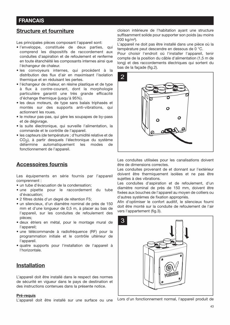
Prerequisites
The appliance must be installed on an internal surface or
wall of the home structurally suited to holding its weight
(at least 200 kg/m2).
The appliance must not be installed in areas where the
temperature may drop below 0°C.
The site chosen for installation must take into account
the position of the power supply cable (1.5.m long) and
the electrical connections that come out of the
underside of the appliance (Fig. 3).
The air distribution ducts must be of the correct size.
The ducts to and from the exterior must be thermally
insulated and not subject to vibrations. The inlet and
outlet ducts, of a standard diameter of 150 mm, must be
secured to the corresponding spigots of the appliance
by means of clips or other suitable fastening systems.
In order to optimize acoustic levels a silencer must be
mounted on the air feed into the home (Pg.4).
3
2
24
ENGLISH
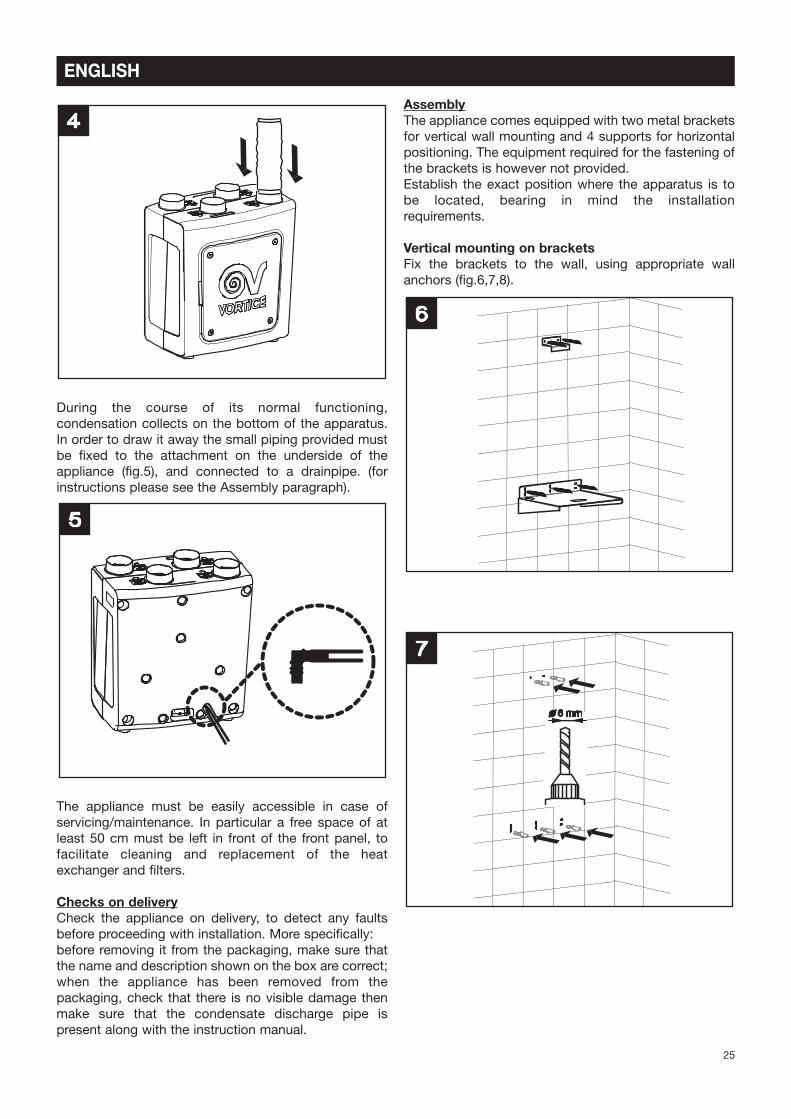
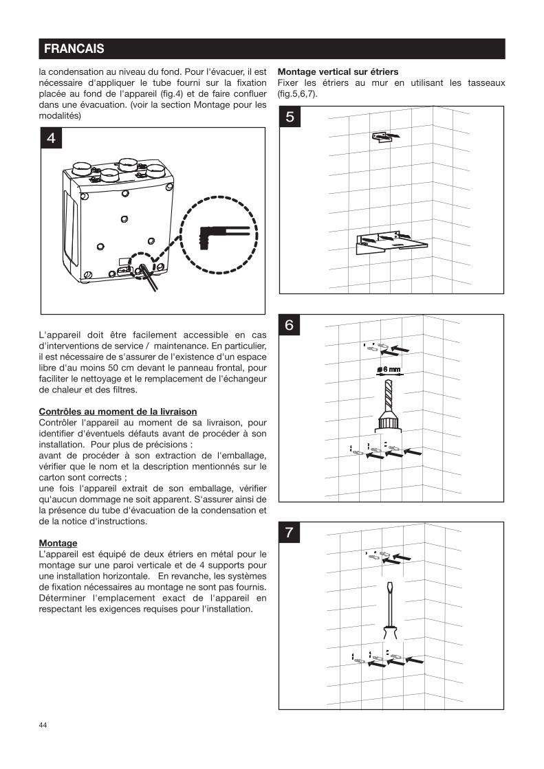
During the course of its normal functioning,
condensation collects on the bottom of the apparatus.
In order to draw it away the small piping provided must
be Pxed to the attachment on the underside of the
appliance (Pg.5), and connected to a drainpipe. (for
instructions please see the Assembly paragraph).
The appliance must be easily accessible in case of
servicing/maintenance. In particular a free space of at
least 50 cm must be left in front of the front panel, to
facilitate cleaning and replacement of the heat
exchanger and Plters.
Checks on delivery
Check the appliance on delivery, to detect any faults
before proceeding with installation. More speciPcally:
before removing it from the packaging, make sure that
the name and description shown on the box are correct;
when the appliance has been removed from the
packaging, check that there is no visible damage then
make sure that the condensate discharge pipe is
present along with the instruction manual.
Assembly
The appliance comes equipped with two metal brackets
for vertical wall mounting and 4 supports for horizontal
positioning. The equipment required for the fastening of
the brackets is however not provided.
Establish the exact position where the apparatus is to
be located, bearing in mind the installation
requirements.
Vertical mounting on brackets
Fix the brackets to the wall, using appropriate wall
anchors (Pg.6,7,8).
7
6
5
4
25
ENGLISH
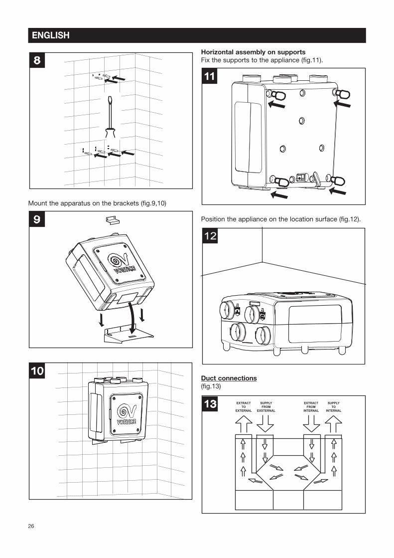
Mount the apparatus on the brackets (Pg.9,10)
Horizontal assembly on supports
Fix the supports to the appliance (Pg.11).
Position the appliance on the location surface (Pg.12).
Duct connections
(Pg.13)
13 EXTRACT
TO
EXTERNAL
SUPPLY
FROM
EXSTERNAL
EXTRACT
FROM
INTERNAL
SUPPLY
TO
INTERNAL
12
11
10
9
8
26
ENGLISH
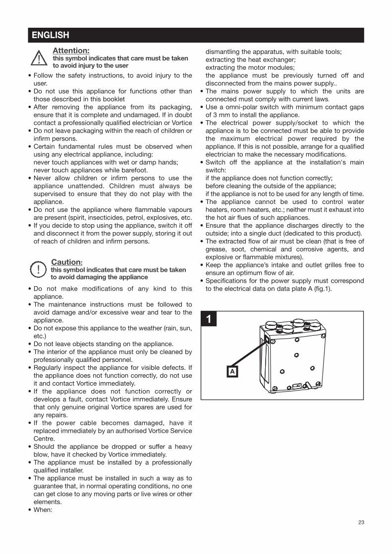
The appliance’s connecting spigots have a standard
diameter of 150 mm . Rigid or Vexible ducts may be
connected to these inlet and outlet spigots. Each
connection is labelled to specify the direction of the air
Vow, as per the following Pgures.
Stale air flow towards the outside (extract to
external) (Pg.14)
This outlet is used to expel the stale air outside once it
has been processed by the heat exchanger. The duct to
which the outlet is to be connected must be thermally
insulated (to avoid the formation of condensate on its
inside and outside parts), and equipped with devices to
dampen any vibration. If the terminal is on a roof it is
mandatory to use a suitable device designed to avoid
the formation of condensation and rain water
inPltrations.
Fresh air intake from the outside (supply from
external) (Pg.15)
This inlet is used to supply the air from outside; the duct
must be thermally insulated and provided with devices
capable of dampening any vibration. If the terminal is on
a roof it is mandatory to use a suitable device designed
to avoid the formation of condensation and rain water
inPltrations.
Stale air flow extractor from the home (extract from
internal) (Pg.16)
This inlet is used to introduce the air extracted from
within the house into the appliance. The duct requires
thermal insulation.
Clear air inlet into the home
(supply to internal) (Pg.17)
This outlet is used to introduce external air into the
home, following treatment in the heat exchanger. In
order to guarantee the optimum level of acoustic
comfort, the silencer provided must be Pxed to this
outlet.
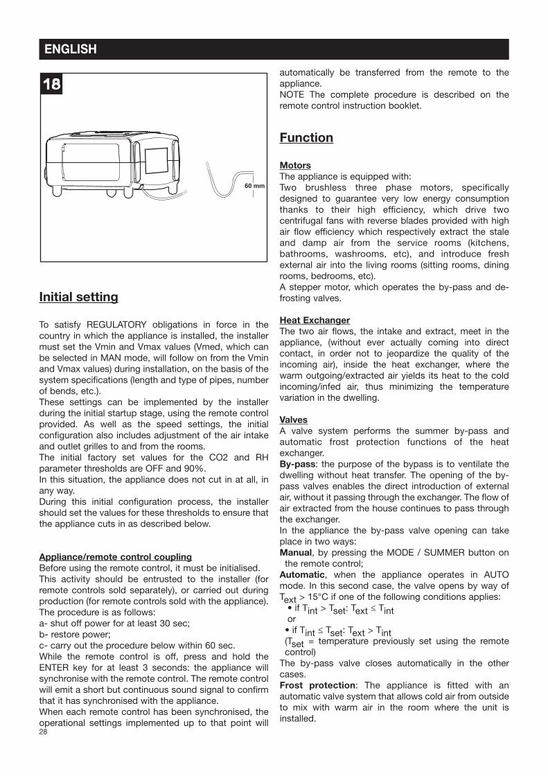
Connection of the condensation draining tube
The connection point for this tube is located on the
underside of the appliance. The condensation drainage
can be achieved by connecting a Vexible tube, supplied
with the appliance, with an internal diameter of
approximately 19 mm. To avoid the formation of air
locks a siphon must be created with the tube, as shown
in the Pg.18. Cut the tube end diagonally.
The condensation drainage can also be routed to the
home drainage system.
17
16
15
14
27
ENGLISH
Initial setting
To satisfy REGULATORY obligations in force in the
country in which the appliance is installed, the installer
must set the Vmin and Vmax values (Vmed, which can
be selected in MAN mode, will follow on from the Vmin
and Vmax values) during installation, on the basis of the
system speciPcations (length and type of pipes, number
of bends, etc.).
These settings can be implemented by the installer
during the initial startup stage, using the remote control
provided. As well as the speed settings, the initial
conPguration also includes adjustment of the air intake
and outlet grilles to and from the rooms.
The initial factory set values for the CO2 and RH
parameter thresholds are OFF and 90%.
In this situation, the appliance does not cut in at all, in
any way.
During this initial conPguration process, the installer
should set the values for these thresholds to ensure that
the appliance cuts in as described below.
Appliance/remote control coupling
Before using the remote control, it must be initialised.
This activity should be entrusted to the installer (for
remote controls sold separately), or carried out during
production (for remote controls sold with the appliance).
The procedure is as follows:
a- shut off power for at least 30 sec;
b- restore power;
c- carry out the procedure below within 60 sec.
While the remote control is off, press and hold the
ENTER key for at least 3 seconds: the appliance will
synchronise with the remote control. The remote control
will emit a short but continuous sound signal to conPrm
that it has synchronised with the appliance.
When each remote control has been synchronised, the
operational settings implemented up to that point will
automatically be transferred from the remote to the
appliance.
NOTE The complete procedure is described on the
remote control instruction booklet.
Function
Motors
The appliance is equipped with:
Two brushless three phase motors, speciPcally
designed to guarantee very low energy consumption
thanks to their high efPciency, which drive two
centrifugal fans with reverse blades provided with high
air Vow efPciency which respectively extract the stale
and damp air from the service rooms (kitchens,
bathrooms, washrooms, etc), and introduce fresh
external air into the living rooms (sitting rooms, dining
rooms, bedrooms, etc).
A stepper motor, which operates the by-pass and de-
frosting valves.
Heat Exchanger
The two air Vows, the intake and extract, meet in the
appliance, (without ever actually coming into direct
contact, in order not to jeopardize the quality of the
incoming air), inside the heat exchanger, where the
warm outgoing/extracted air yields its heat to the cold
incoming/infed air, thus minimizing the temperature
variation in the dwelling.
Valves
A valve system performs the summer by-pass and
automatic frost protection functions of the heat
exchanger.
By-pass: the purpose of the bypass is to ventilate the
dwelling without heat transfer. The opening of the by-
pass valves enables the direct introduction of external
air, without it passing through the exchanger. The Vow of
air extracted from the house continues to pass through
the exchanger.
In the appliance the by-pass valve opening can take
place in two ways:
Manual, by pressing the MODE / SUMMER button on
the remote control;
Automatic, when the appliance operates in AUTO
mode. In this second case, the valve opens by way of
Text > 15°C if one of the following conditions applies:
• if Tint > Tset: Text ≤ Tintor
• if Tint ≤ Tset: Text > Tint(Tset = temperature previously set using the remote
control)
The by-pass valve closes automatically in the other
cases.
Frost protection: The appliance is Ptted with an
automatic valve system that allows cold air from outside
to mix with warm air in the room where the unit is
installed.
18
60 mm
28
ENGLISH
The combined action of this valve and the automatic
adjustment of the airVows extracted from and entering
the rooms prevents the formation of frost on the heat
exchanger; this device consists of a valve which allows
the incoming cold air to mix with the warmer air from the
room in which the appliance is installed.
The frost protection procedure on the appliance works
as follows:
the valve begins to open automatically; at the same
time, the air intake fan increases in speed so as to
increase airVow.
If this action is insufPcient, the outside air intake fan
speed is reduced, to mimimise the amount of heat
needed to heat it up.
If even this action is insufPcient, the extractor fan for the
warm air from inside increases its speed, to increase the
heat contribution available, while the intake fan remains
at minimum speed.
Lastly, if even this measure should be insufPcient when
faced with particularly bad external climate conditions,
in the absence of an optional heating element, the air
intake fan stops completely and the valve is closed,
while the stale air extractor fan continues operating.
After a certain period of time, the air intake fan starts
again at minimum speed, the valve re-opens and the
external conditions are checked again; if in the
meantime the temperature exceeds the threshold limit,
the actions described above take place in reverse order.
If atmospheric conditions in the room are beyond the
potential of the above-mentioned system, the (optional)
heating element situated upstream of the heat recovery
unit in the fresh air duct automatically cuts in for the
precise time dictated by the appliance and thus ensures
that the aim is achieved.
N.B.
The frost protection switching on prevents any change
to the status of the appliance. Any commands made will
not be carried out by the appliance, and the message
“DEF” will be displayed temporarily.
This will remain on the screen for a few seconds and will
then disappear and reappear every 15 minutes for as
long as the heating element is powered by automatic
data updates from the appliance to the remote control.
If a malfunction is detected in the heater, the word “ICE”
will Vash on the remote control display and will be
followed by a single beep. Carry out the RESET
procedure. The heating element icon will continue to
Vash, to indicate the heater fault. In this case, contact
the Technical Support Centre.
IMPORTANT: make sure that nothing is placed close to
the anti-frost valve, as this could obstruct its normal
operation.
Filters
Two F5 Plters, placed inside the inlet and extraction
channels close to the heat exchanger and accessible by
removing the front panel, safeguard it from the
impurities contained in the extracted stale air and avoid
the introduction of polluted air into the dwelling served
by the system.
A further optional Plter, of class F7, placed in the internal
duct after the F5 Plter, can provide an additional Pltering
capability.
The state of Plter clogging is constantly monitored by
the system, completely automatically. The need for
maintenance/replacement is signalled, both visually and
acoustically, on the remote control.
Sensors
The appliance is equipped with three temperature
sensors, one relative humidity sensor, which integrates a
further temperature sensor, and a CO2 sensor. More
speciPcally, if the relative humidity, CO2 and
temperature sensors detect values above the threshold
levels, the appliance operation adapts automatically, to
restore normal environmental conditions or at least in
line with those set.
IMPORTANT
Before the appliance will work correctly, the CO2/RH(%)
sensor needs an average of 1 hour for auto-calibration
purposes.
29
ENGLISH
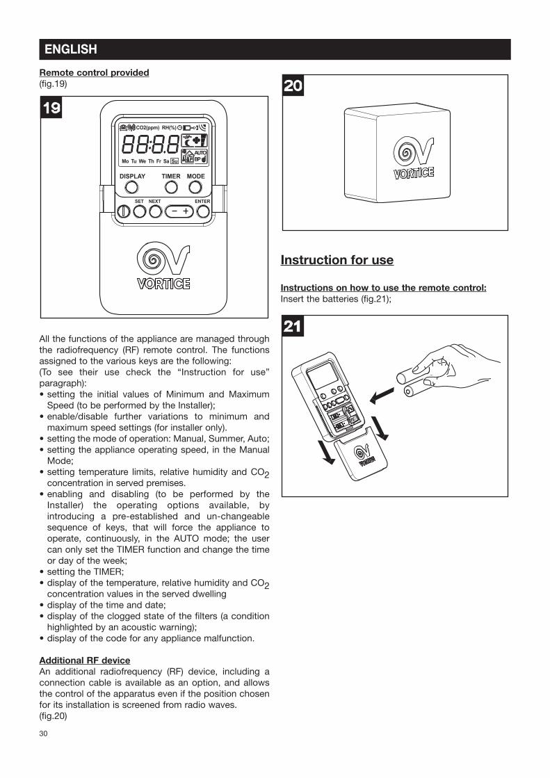
Remote control provided
(Pg.19)
All the functions of the appliance are managed through
the radiofrequency (RF) remote control. The functions
assigned to the various keys are the following:
(To see their use check the “Instruction for use”
paragraph):
• setting the initial values of Minimum and Maximum
Speed (to be performed by the Installer);
• enable/disable further variations to minimum and
maximum speed settings (for installer only).
• setting the mode of operation: Manual, Summer, Auto;
• setting the appliance operating speed, in the Manual
Mode;
• setting temperature limits, relative humidity and CO2concentration in served premises.
• enabling and disabling (to be performed by the
Installer) the operating options available, by
introducing a pre-established and un-changeable
sequence of keys, that will force the appliance to
operate, continuously, in the AUTO mode; the user
can only set the TIMER function and change the time
or day of the week;
• setting the TIMER;
• display of the temperature, relative humidity and CO2concentration values in the served dwelling
• display of the time and date;
• display of the clogged state of the Plters (a condition
highlighted by an acoustic warning);
• display of the code for any appliance malfunction.
Additional RF device
An additional radiofrequency (RF) device, including a
connection cable is available as an option, and allows
the control of the apparatus even if the position chosen
for its installation is screened from radio waves.
(Pg.20)
Instruction for use
Instructions on how to use the remote control:
Insert the batteries (Pg.21);
21
20
DISPLAY TIMER MODE
SET NEXT ENTER
19
CO2(ppm) RH(%)
Mo Tu We Th Fr Sa Su
AUTO
BP°CF
30
ENGLISH
ON/OFF button (Pg.22)
Enables the appliance to be turned on and off. The
command is performed only if the button is pressed for
at least 0.5 seconds. With the appliance off the time and
day of the week are displayed. This function may be
disabled. On turning the appliance on the AUTO mode
is activated at a speed of Vmin.
SET button (Pg.23)
Sets the following parameters. To move from one
parameter/Peld to the next, press NEXT.
Time/day setting (Pg.23a):
• press SET to view the parameter;
• set the value of the flashing field with the + and - keys;
the sequence will be: HOURS, MINUTES, DAY.
Temperature setting (Pg.23b):
• to view the parameter, press: SET and NEXT (several
times);
• set the value of the flashing field with the + and - keys;
the sequence will be: C/F (unit of measurement, °C for
degrees Celsius, F for degrees Fahrenheit), internal T
value (from 15°C to 30°C, in steps of 1°C).
Relative humidity setting (Pg.23c):
• to view the parameter, press: SET and NEXT (several
times);
• set the value of the flashing field with the + and - keys
(from 40% to 90%, in steps of 5%).
RH(%)
23c
23b
°C
23a
23
DISPLAY TIMER MODE
SET NEXT ENTER
Su
AUTO
22
DISPLAY TIMER MODE
SET NEXT ENTER
Su
AUTO
31
ENGLISH
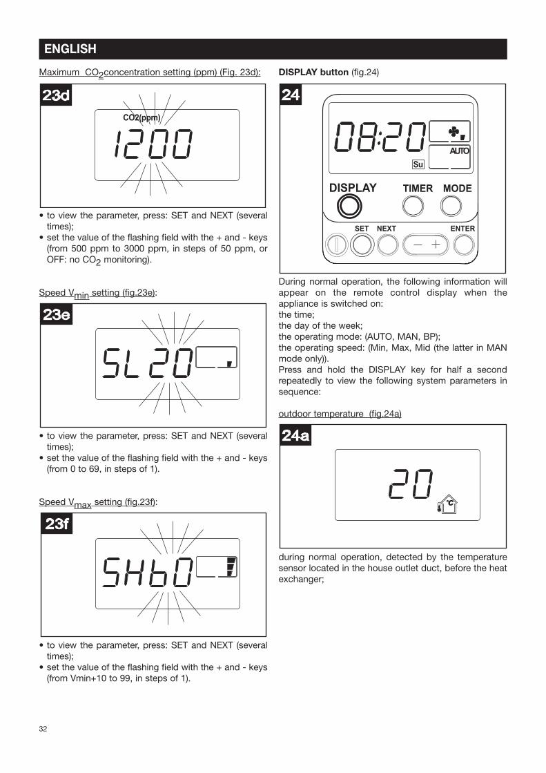
Maximum CO2concentration setting (ppm) (Fig. 23d):
• to view the parameter, press: SET and NEXT (several
times);
• set the value of the flashing field with the + and - keys
(from 500 ppm to 3000 ppm, in steps of 50 ppm, or
OFF: no CO2 monitoring).
Speed Vmin setting (Pg.23e):
Vmin setting (Pg.23e):
• to view the parameter, press: SET and NEXT (several
times);
• set the value of the flashing field with the + and - keys
(from 0 to 69, in steps of 1).
Speed Vmax setting (Pg.23f):
• to view the parameter, press: SET and NEXT (several
times);
• set the value of the flashing field with the + and - keys
(from Vmin+10 to 99, in steps of 1).
DISPLAY button (Pg.24)
During normal operation, the following information will
appear on the remote control display when the
appliance is switched on:
the time;
the day of the week;
the operating mode: (AUTO, MAN, BP);
the operating speed: (Min, Max, Mid (the latter in MAN
mode only)).
Press and hold the DISPLAY key for half a second
repeatedly to view the following system parameters in
sequence:
outdoor temperature (Pg.24a)
during normal operation, detected by the temperature
sensor located in the house outlet duct, before the heat
exchanger;
24a
°C
24
DISPLAY TIMER MODE
SET NEXT ENTER
Su
AUTO
23f
23e
CO2(ppm)
23d
32
ENGLISH
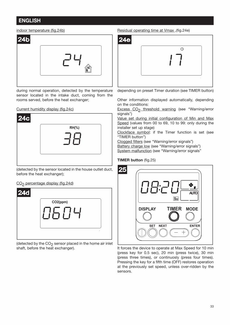
indoor temperature (Pg.24b)
during normal operation, detected by the temperature
sensor located in the intake duct, coming from the
rooms served, before the heat exchanger;
Current humidity display (Pg.24c)
(detected by the sensor located in the house outlet duct,
before the heat exchanger);
CO2 percentage display (Pg.24d)
(detected by the CO2 sensor placed in the home air inlet
shaft, before the heat exchanger).
Residual operating time at Vmax ,(Pg.24e)
depending on preset Timer duration (see TIMER button)
Other information displayed automatically, depending
on the conditions:
Excess CO2 threshold warning (see “Warning/error
signals")
Value set during initial conPguration of Min and Max
Speed (values from 00 to 69, 10 to 99: only during the
installer set up stage)
Clockface symbol: if the Timer function is set (see
“TIMER button”)
Clogged Plters (see “Warning/error signals”)
Battery charge low (see “Warning/error signals”)
System malfunction (see “Warning/error signals”
TIMER button (Pg.25)
It forces the device to operate at Max Speed for 10 min
(press key for 0.5 sec), 20 min (press twice), 30 min
(press three times), or continuosly (press four times).
Pressing the key for a Pfth time (OFF) restores operation
at the previously set speed, unless over-ridden by the
sensors.
25
DISPLAY TIMER MODE
SET NEXT ENTER
Su
AUTO
24e
CO2(ppm)
24d
RH(%)
24c
24b
°C
33
ENGLISH
The display will also show (Pg.25a):
• The TIMER icon;
• The duration set (10,20,30,CO;
If the programming time has elapsed (or if you press the
TIMER key Pve times repeatedly until OFF), the
appliance will go back to the previously set function
mode.
MODE button (Pg.26)
Used to select one of the available operating modes
(MAN, BP, AUTO). Press the key to switch between
modes.
AUTO (Pg.26a):
the operating speed is automatically set by the system,depending on the environmental conditions detected bythe sensors; if necessary the by-pass and frostprotection valves are activated automatically;
Bypass function activation is indicated by the Vashing"BP" icon on the display.
MAN (Pg.26b):
the operating speed is decided by the user (the CO2and relative humidity sensors can still trigger a shift toMax speed if necessary);
BP (Pg.26c):
this forces the opening of the by-pass valve, irrespectiveof the actual desired internal, desired or externaltemperature values.The shift from one operating mode to the other isachieved by pressing the MODE button for at least 0.5seconds
NEXT, - +, ENTER buttons (Pg.27)
Already described in other parts of this document.
27
DISPLAY TIMER MODE
SET NEXT ENTER
Su
AUTO
Su
26c
BP
Su
26b
Su
26a
AUTO
26
DISPLAY TIMER MODE
SET NEXT ENTER
Su
AUTO
25a
34
ENGLISH
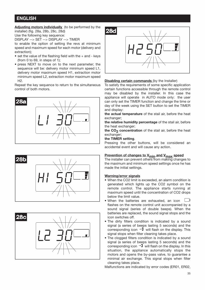
Adjusting motors individually (to be performed by the
installer) (Pg. 28a, 28b, 28c, 28d)
Use the following key sequence:
DISPLAY --> SET --> DISPLAY --> TIMER
to enable the option of setting the revs at minimum
speed and maximum speed for each motor (delivery and
extraction);
• set the value of the Vashing Peld with the + and - keys
(from 0 to 69, in steps of 1);
• press NEXT to move on to the next parameter; the
sequence will be: delivery motor minimum speed L1,
delivery motor maximum speed H1, extraction motor
minimum speed L2, extraction motor maximum speed
H2.
Repeat the key sequence to return to the simultaneous
control of both motors.
Disabling certain commands (by the Installer)
To satisfy the requirements of some speciPc application
certain functions accessible through the remote control
may be disabled by the installer. In this case the
appliance will operate in AUTO mode only: the user
can only set the TIMER function and change the time or
day of the week using the SET button to set the TIMER
and display:
the actual temperature of the stail air, before the heat
exchanger;
the relative humidity percentage of the stail air, before
the heat exchanger;
the CO2 concentration of the stail air, before the heat
exchanger;
the TIMER setting.
Pressing the other buttons, will be considered an
accidental event and will cause any action.
Prevention of changes to Vmin and Vmax speed
The installer can prevent others from making changes to
the maximum and minimum speed settings once he has
made the initial settings.
Warning/error signals
• When the CO2 limit is exceeded, an alarm condition is
generated which lights up the CO2 symbol on the
remote control. The appliance starts running at
maximum speed until the concentration of CO2 drops
below the limit value.
• When the batteries are exhausted, an icon
Vashes on the remote control unit accompanied by a
sound signal (series of double beeps). When the
batteries are replaced, the sound signal stops and the
icon switches off.
• The dirty Plters condition is indicated by a sound
signal (a series of beeps lasting 5 seconds) and the
corresponding icon will Vash on the display. This
signal stops when Plter cleaning takes place.
• The clogged Plters condition is indicated by a sound
signal (a series of beeps lasting 5 seconds) and the
corresponding icon will Vash on the display. In this
situation, the appliance automatically stops the
motors and opens the by-pass valve, to guarantee a
minimal air exchange. This signal stops when Plter
cleaning takes place.
Malfunctions are indicated by error codes (ER01, ER02,
28d
28c
28b
28a
35
ENGLISH
etc...) on the display and by a series of double beeps.
These warnings persist until normal appliance operating
conditions have been restored. Malfunctions will be
indicated as follows:
ER01: by-pass/de-frosting valve blocked
ER02: motor driving outside air intake fan blocked
ER03: motor driving stale air exhaust fan blocked
ER04: remote control not receiving signals from
appliance
ER05: replace the Plters
ER06: temperature sensor in the outdoor fresh air intake
duct, upstream of the exchanger, not active
ER07: temperature sensor in the outdoor fresh air intake
duct, downstream of the exchanger, not active
ER08: temperature sensor in the stale air outlet duct
leaving the household, downstream of the exchanger,
not active
ER09: Relative Humidity sensor in the stale air outlet
duct leaving the household, upstream of the exchanger,
not active
ER10: CO2 sensor in the stale air outlet duct leaving the
household, upstream of the exchanger, not active
ER12: outdoor temperature higher than the limit value
ER14: indoor temperature higher than the limit value.
N.B.
It should be noted that error signals (ER01, ER02 and
ER03, ER12, ER14 codes) caused by critical appliance
malfunctions will cause the appliance to stop working
until the problem has been resolved. In this case, the
beep will sound for 30 seconds; after this time it will
stop and an error message will remain on the display. In
other cases, once a problem has been signalled, the
appliance continues to run in the mode set previously.
The beep will sound for 5 seconds; after this time it will
stop and an error message will remain on the display.
Under these circumstances, the user will not be able to
change the operating mode (e.g. MAN or BP).
Reset error code
To stop the error code from being displayed (if the
remote control has not been disabled) press the
following keys one after the other: DISPLAY --> “-” -->
DISPLAY --> “+”.
After the RESET, the appliance starts running in AUTO
mode, in line with the standard initial parameters, only if
the problem causing the error has been resolved.
Similarly, if the appliance power supply has been cut off,
when it is restored the appliance will resume operation
in AUTO mode, in accordance with the standard initial
parameters.
Fuse
The appliance has 2 A fuse Ptted in series with the
power supply cable. (Pg.29)
In the event of repeated fuse failures, the appliance
should be checked by a trained electrician.
Maintenance/Cleaning
Filters
The periodical cleaning and maintenance of the Plters is
left to the user. The Plters must be kept clean to ensure
a correct and healthy operation of the appliance.
It is advisable to replace the Plters once a year. To
access the Plters follow the instructions below:
switch off the appliance (ON/OFF button);
wait 15 seconds;
disconnect the appliance from the mains power
supply;
extract the filters from the appliance (Pg.30,31,32);
30
29
36
ENGLISH
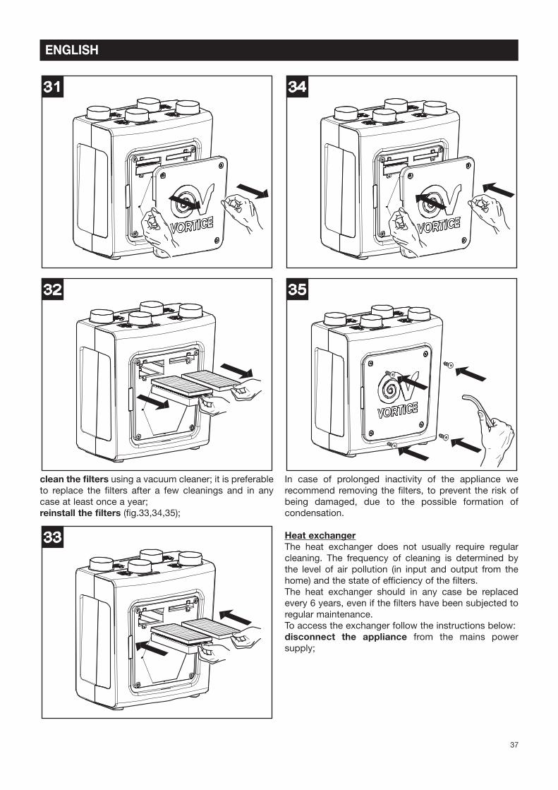
clean the filters using a vacuum cleaner; it is preferable
to replace the Plters after a few cleanings and in any
case at least once a year;
reinstall the filters (Pg.33,34,35);
In case of prolonged inactivity of the appliance we
recommend removing the Plters, to prevent the risk of
being damaged, due to the possible formation of
condensation.
Heat exchanger
The heat exchanger does not usually require regular
cleaning. The frequency of cleaning is determined by
the level of air pollution (in input and output from the
home) and the state of efPciency of the Plters.
The heat exchanger should in any case be replaced
every 6 years, even if the Plters have been subjected to
regular maintenance.
To access the exchanger follow the instructions below:
disconnect the appliance from the mains power
supply;
35
34
33
32
31
37
ENGLISH
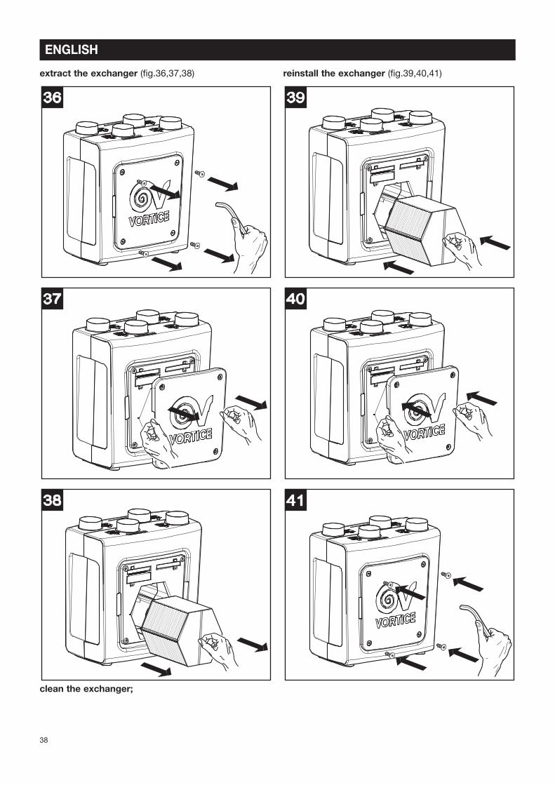
extract the exchanger (Pg.36,37,38)
clean the exchanger;
reinstall the exchanger (Pg.39,40,41)
41
40
39
38
37
36
38
ENGLISH
Replacement of the remote control batteries
open the battery compartment cover (fig.42);
insert 2 AA type batteries ensuring that the polarities
shown on the bottom of the compartment are complied
with; replace the battery compartment cover.
Important information concerning
the environmentally compatible
disposal
IN CERTAIN EUROPEAN UNION COUNTRIES THIS
PRODUCT DOES NOT FALL WITHIN THE
REQUIREMENTS OF THE NATIONAL LAWS
IMPLEMENTING DIRECTIVE WEEE, AND IN THESE
COUNTRIES THE PRODUCT IS NOT SUBJECT TO
SEPARATE DISPOSAL OPERATIONS AT THE END OF
ITS WORKING LIFE.
This product conforms to EU Directive2002/96/EC.
This appliance bears the symbol of the
barred waste bin. This indicates that, at
the end of its useful life, it must not be
disposed of as domestic waste, but must
be taken to a collection centre for waste
electrical and electronic equipment, or returned to a
retailer on purchase of a replacement.
It is the user's responsibility to dispose of this appliance
through the appropriate channels at the end of its useful
life. Failure to do so may incur the penalties established
by laws governing waste disposal.
Proper differential collection, and the subsequent
recycling, processing and environmentally compatible
disposal of waste equipment avoids unnecessary
damage to the environment and possible related
healthrisks, and also promotes recycling of the materials
used in the appliance.
For further information on waste collection and disposal,
contact your local waste disposal service, or the shop
from which you purchased the appliance.
Manufacturers and importers fulfil their responsibilities
for recycling, processing and environmentally
compatible disposal either directly or by participating in
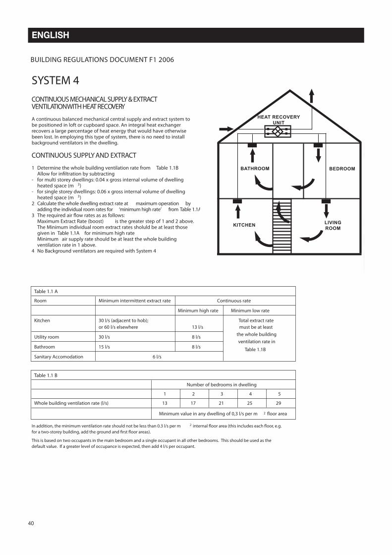
Kitchen 30 l/s (adjacent to hob); Total extract rate
or 60 l/s elsewhere 13 l/s must be at least
Utility room 30 l/s 8 l/sthe whole building
Bathroom 15 l/s 8 l/sventilation rate in
Sanitary Accomodation 6 l/s
Table 1.1B
Table 1.1 B
Number of bedrooms in dwelling
1 2 3 4 5
Whole building ventilation rate (l/s) 13 17 21 25 29
Minimum value in any dwelling of 0,3 l/s per m 2 4oor area
BUILDING REGULATIONS DOCUMENT F1 2006
CONTINUOUS MECHANICALSUPPLY & EXTRACT
VENTILATION WITH HEAT RECOVERY
A continuous balanced mechanical central supply and extract system tobe positioned in loft or cupboard space. An integral heat exchangerrecovers a large percentage of heat energy that would have otherwisebeen lost. In employing this type of system, there is no need to installbackground ventilators in the dwelling.
CONTINUOUS SUPPLY AND EXTRACT
1 Determine the whole building ventilation rate from Table 1.1BAllow for in8ltration by subtracting
- for multi storey dwellings: 0.04 x gross internal volume of dwellingheated space (m 3)
- for single storey dwellings: 0.06 x gross internal volume of dwellingheated space (m 3)
2 Calculate the whole dwelling extract rate at maximum operation byadding the individual room rates for ‘minimum high rate’ from Table 1.1A
3 The required air �ow rates as as follows:Maximum Extract Rate (boost) is the greater step of 1 and 2 above.The Minimum individual room extract rates sholuld be at least thosegiven in Table 1.1A for minimum high rateMinimum air supply rate should be at least the whole buildingventilation rate in 1 above.
4 No Background ventilators are required with System 4
In addition, the minimum ventilation rate should not be less than 0.3 l/s per m 2 internal 4oor area (this includes each 4oor, e.g.
for a two-storey building, add the ground and 8rst 4oor areas).
This is based on two occupants in the main bedroom and a single occupant in all other bedrooms. This should be used as the
default value. If a greater level of occupance is expected, then add 4 l/s per occupant.
SYSTEM 4
!"#$%&'()*+,%-.'"/0&(( 12 !2!334((56 3((7+8%9+(:5
BATHROOM BEDROOM
HEAT RECOVERY
UNIT
KITCHENLIVING
ROOM
Conformité avec les normes de
construction
Les lois les plus récentes visant à maîtriser la
consommation d'énergie imposent le respect d'une
série de contraintes liées aux prestations fournies et à la
consommation des appareils de ventilation.
En particulier, l'édition 2006 du règlement britannique