Vortex formation in a cavity with oscillating wallsG. Ovando,1 H. Juárez,2 G. Huelsz,1 and E. Ramos1,3,a�
1Centro de Investigación en Energía, UNAM, Ap. P. 34, 62580 Temixco, Morelos, Mexico2Departamento de Matemáticas, UAM-I, Ap. P. 55-534, 09340 Mexico D. F., Mexico3Max Planck Institute for the Physics of Complex Systems, Noethnitzer Strasse 38,01187 Dresden, Germany
�Received 1 August 2008; accepted 15 October 2008; published online 3 February 2009�
The oscillatory flow generated by the relative periodicmotion of the walls containing a fluid has been studied indetail due to the numerous technologically relevant situationswhere these conditions occur. Perhaps the most importantapplication is the problem of a piston moving in a cylindricalcontainer as it happens in internal combustion engines,1 butother examples such as a device for measuring the surfacedilatational viscosity of a gas/liquid interface2 have moti-vated other important aspects of the analysis as well. A studyclosely related to the present investigation was reported byO’Brien.3 The analysis consisted in numerically solving amodel for the flow generated by the in-phase sinusoidal mo-tion of two opposite walls of a two-dimensional �2D� con-tainer with aspect ratio of 0.5. The flow is assumed to besymmetric and the emphasis of the study was on the un-steady separation.
Studies have been done both for a moving cylinder wallwith fixed piston and for a moving piston. According toTabaczynski et al.,4 the flow near the corner is equivalent inboth cases provided ��t /UwT�1, where � is the kinematicviscosity, t is the time, Uw is the instantaneous piston speed,and T is the period. The pioneering experimental observa-tions of Tabaczynski et al.4 have shown that the fluid motion
is a sink-type flow when the cylinder wall retreats from thepiston and a spiral ring vortex motion near the piston faceand cylinder wall interface when the cylinder wall movestoward the piston, both for constant and oscillatory velocityof the walls. The flow in the vicinity of the corner as the wallmoves toward a fixed piston with a steady motion was stud-ied theoretically by Taylor,5 assuming that the inertial effectscan be neglected; Hancock et al.6 generalized this analysisby including the inertia effects. In this region, the velocitygradients are large and a discontinuity exists in the velocityfield at the junction of the moving piston relative to the wall.Also, close to the corner, viscous forces are much larger thaninertial ones. Using an order of magnitude argument,Batchelor7 indicates that the distance r from the corner towhere a steady viscous solution is applicable is of the orderof r�� /Uw, but experiments of Allen and Chong8 haveshown that the validity of the viscous solution is significantlylarger than � /Uw.
Tabaczynski et al.4 and Allen and Chong8 studied thedimension of the vortex generated when the lateral wallmoves toward the piston. The first authors considered con-stant and sinusoidal wall speed while Allen and Chong8 ob-served the phenomenon for constant or power law wallspeed. Analysis and numerical studies on incompressibleflows are done considering isothermal conditions.
The flow in a rectangular cavity driven by the sinusoidalmotion of one of the walls in its own plane was analyzed inRefs. 9–11. The main objective was the identification of the
a�Author to whom correspondence should be addressed. Telephone: �52�55�562-29701. Fax: �52�55�562-29741. Electronic mail:[email protected].
stability limits of the time-periodic, 2D base state. Their re-sults include the determination of regions in the 2D �Re,St�parametric space, where Re is the Reynolds number based onmaximum wall velocity and St is the Stokes number definedin terms of the height of the cavity. The system may adoptone of three possible flow regimes: an essentially 2D time-periodic flow, a time-periodic three-dimensional �3D� flow,and a 3D space and time irregular flow. In the limit where thespanwise direction is infinite, the range of parameters ex-plored was 500�Re�1400 and 0�St�200. Their resultsindicate that for flows with Re�520, the flow is 2D, and thatthe neutral stability line dividing the 2D and 3D flow regionsdisplays a local minimum at Re=520, St=20.
In this work, we analyzed the vortex formation in all thecavity with vertical oscillating walls, for Re=50, 500, and1000 with Y =0.2, 0.4, and 0.8. An important result is theidentification of a 2D instability in the flow at relatively largeamplitude of the wall motion and Reynolds numbers.
II. PROBLEM FORMULATION
A. Physical and geometry description
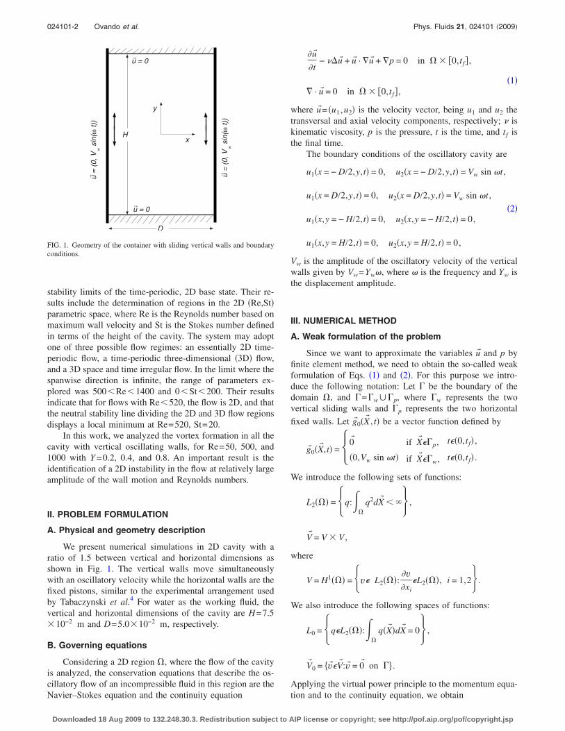
We present numerical simulations in 2D cavity with aratio of 1.5 between vertical and horizontal dimensions asshown in Fig. 1. The vertical walls move simultaneouslywith an oscillatory velocity while the horizontal walls are thefixed pistons, similar to the experimental arrangement usedby Tabaczynski et al.4 For water as the working fluid, thevertical and horizontal dimensions of the cavity are H=7.5�10−2 m and D=5.0�10−2 m, respectively.
B. Governing equations
Considering a 2D region �, where the flow of the cavityis analyzed, the conservation equations that describe the os-cillatory flow of an incompressible fluid in this region are theNavier–Stokes equation and the continuity equation
�u�
�t− ��u� + u� · �u� + �p = 0 in � � �0,tf� ,
�1�� · u� = 0 in � � �0,tf� ,
where u� = �u1 ,u2� is the velocity vector, being u1 and u2 thetransversal and axial velocity components, respectively; � iskinematic viscosity, p is the pressure, t is the time, and tf isthe final time.
The boundary conditions of the oscillatory cavity are
Vw is the amplitude of the oscillatory velocity of the verticalwalls given by Vw=Yw�, where � is the frequency and Yw isthe displacement amplitude.
III. NUMERICAL METHOD
A. Weak formulation of the problem
Since we want to approximate the variables u� and p byfinite element method, we need to obtain the so-called weakformulation of Eqs. �1� and �2�. For this purpose we intro-duce the following notation: Let be the boundary of thedomain �, and =w�p, where w represents the twovertical sliding walls and p represents the two horizontal
fixed walls. Let g�0�X� , t� be a vector function defined by
g�0�X� ,t� =�0� if X� p, t�0,tf� ,
�0,Vw sin �t� if X� w, t�0,tf� .�
We introduce the following sets of functions:
L2��� = �q:��
q2dX� � �� ,
V� = V � V ,
where
V = H1��� = �v L2���:�v�xi
L2���, i = 1,2� .
We also introduce the following spaces of functions:
L0 = �qL2���:��
q�X� �dX� = 0� ,
V� 0 = v�V� :v� = 0� on .
Applying the virtual power principle to the momentum equa-tion and to the continuity equation, we obtain
→u = 0
→u = 0
H
→ u=
(0,V
wsi
n(ω
t))
→ u=
(0,V
wsi
n(ω
t))
D
x
y
FIG. 1. Geometry of the container with sliding vertical walls and boundaryconditions.
024101-2 Ovando et al. Phys. Fluids 21, 024101 �2009�
Downloaded 18 Aug 2009 to 132.248.30.3. Redistribution subject to AIP license or copyright; see http://pof.aip.org/pof/copyright.jsp
��� �u�
�t· v� + �u� · ��u� · v��dX� + ��
�
�u�:�v�dX�
− ��
p � · v�dX� = 0, ∀ v�V� 0, �3�
��
q � · u� dX� = 0, ∀ qL2��� , �4�
u��X� ,t� = g�0�X� ,t� on � �0,tf� . �5�
These equations are completed by the following initialconditions:
u��X� ,0� = u�0. �6�
In the above weak formulation, it is reasonable to assume
that u��t�V� and p�t�L0 �see Refs. 12–15�, where we use the
notation u��t� u��X� , t� ∀X� � and t fixed. Similarly for t�0
fixed, p�t� p�X� , t�∀X� �.
B. Finite element approximation
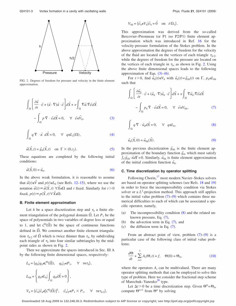
Let h be a space discretization step and h a finite ele-
ment triangulation of the polygonal domain �̄. Let P1 be thespace of polynomials in two variables of degree less or equal
to 1, and let C0��̄� be the space of continuous functions
defined in �̄. We construct another finite element triangula-
tion h/2 of �̄ which is twice thinner than h, by subdividingeach triangle of h into four similar subtriangles by the mid-point sides as shown in Fig. 2.
Then we approximate the spaces introduced in Sec. III Aby the following finite dimensional spaces, respectively:
Lh = qh�qhC0��̄�, qh�TP1, ∀ h ,
L0h = �qhLh���
qhdX� = 0� ,
Vh = v�h�v�h�C0��̄��2, v�h�TP1 � P1, ∀ h/2 ,
V0h = v�hVh�v�h = 0� on � �1 .
This approximation was derived from the so-calledBercovier–Pironneau �or P1 iso P2/P1� finite element ap-proximation which was introduced in Ref. 16 for thevelocity-pressure formulation of the Stokes problem. In theabove approximation the degrees of freedom for the velocityof the fluid are located on the vertices of each triangle h/2,while the degrees of freedom for the pressure are located onthe vertices of each triangle in h, as shown in Fig. 2. Usingthe above finite dimensional spaces leads to the followingapproximation of Eqs. �3�–�6�.
For t�0, find u�h�t�Vh with u�h�t�=g�0h�t� on , phL0h
such that
��� �u�h
�t· v� + �u�h · ��u�h · v��dX� + ��
�
�u�h:�v�dX�
− ��
ph � · v�dX� = 0, ∀ v�V0h, �7�
��
q � · u�hdX� = 0, ∀ qLh, �8�
u�h�X� ,0� = u�0h�X� � . �9�
In the previous discretization g�0h is the finite element ap-proximation of the boundary function g�0, which must satisfy�g�0h ·n�d=0. Similarly, u�0h is finite element approximationof the initial condition function u�0.
C. Time discretization by operator splitting
Following Chorin,17 most modern Navier–Stokes solversare based on operator splitting schemes �see Refs. 18 and 19�in order to force the incompressibility condition via Stokessolver or a L2-projection method. This approach still appliesto the initial value problem �7�–�9� which contains three nu-merical difficulties to each of which can be associated a spe-cific operator, namely,
�a� The incompressibility condition �8� and the related un-known pressure, Eq. �7�,
�b� the advection term in Eq. �7�, and�c� the diffusion term in Eq. �7�.
From an abstract point of view, problem �7�–�9� is aparticular case of the following class of initial value prob-lems:
d�
dt+ �
i=1
3
Ai��,t� = f , ��0� = �0, �10�
where the operators Ai can be multivalued. There are manyoperator splitting methods that can be employed to solve thistype of problem. Here we consider the fractional step schemeof Marechuk–Yaneuko20 type.
Let �t�0 be a time discretization step. Given �0=�0,compute �n+1 from �n by solving
Pressure Velocity
h
h/2
FIG. 2. Degrees of freedom for pressure and velocity in the finite elementapproximation.
024101-3 Vortex formation in a cavity with oscillating walls Phys. Fluids 21, 024101 �2009�
Downloaded 18 Aug 2009 to 132.248.30.3. Redistribution subject to AIP license or copyright; see http://pof.aip.org/pof/copyright.jsp
�n+i/3 − �n+�i−1�/3
�t+ Ai��n+i/3,tn+1� = f i
n+1,
�11�
for i = 1,2,3 with tn = n�t, and �i=1
3
f in+1 = fn+1.
This very simple scheme is only first order accurate �see Ref.20�, but its low order is compensated by good stability androbustness properties. Actually, this scheme can be made sec-ond order accurate by symmetrization �see Refs. 21 and 22for the application of symmetrized splitting schemes to thesolution of the Navier–Stokes equations�.
Applying scheme �11� to Eqs. �7�–�9�, we obtain the fol-lowing three stage scheme �after dropping some of the sub-scripts h�, given u�0=u�0h and assuming we know u�n forn�0:
Step 1. Find u�n+1/3Vh with u�n+1/3=g�0hn+1 on , and
pn+1/3L0h such that
��
u�n+1/3 − u�n
�t· v�dX� − �
�
pn+1/3 � · v�dX�
= 0, ∀ vV0h,
�12�
� q � · u�n+1/3dX� = 0, ∀ qLh.
Step 2. Find u�n+2/3=u��tn+1�, where u��t� is the solution on�tn , tn+1� of the following advection problem:
��
�u��t��t
· v�dX� + ��
�u�n+1/3 · ��u��t� · v�dX� = 0, ∀ vV0h− ,
�13�
u��tn�=u�n+1/3, and u��t�=g�0h�tn+1� on −� �tn , tn+1�, where −
= x� �g�0h ·n��X� ��0 and V0h− = v�Vh �v� =0 on −.
Step 3. Find u�n+1Vh with u�n+1=g�0hn+1 on such that
��
u�n+1 − u�n+2/3
�t· v�dX� +
1
Re�
�
�u�n+1:�v�dX�
= 0, ∀ v�V0h. �14�
Problem �12� is a finite dimensional problem known as asaddle-point system which was solved by a Uzawa/conjugate-gradient algorithm discussed with many details in,e.g., Refs. 15 and 23. Problem �14� is a discrete elliptic sys-tem whose iterative or direct solution is a quite classicalproblem. In this work this elliptic system was solved by aconjugate-gradient method adapted for sparse systems.24 Onthe other hand, solving the pure advection Eq. �13� is a moredelicate issue. This equation can be solved by a method ofcharacteristics as in Refs. 18 and 25. An easier alternative isprovided by the wavelike equation method discussed in Refs.15, 22, and 26. We applied this last method to solve Eq. �13�.
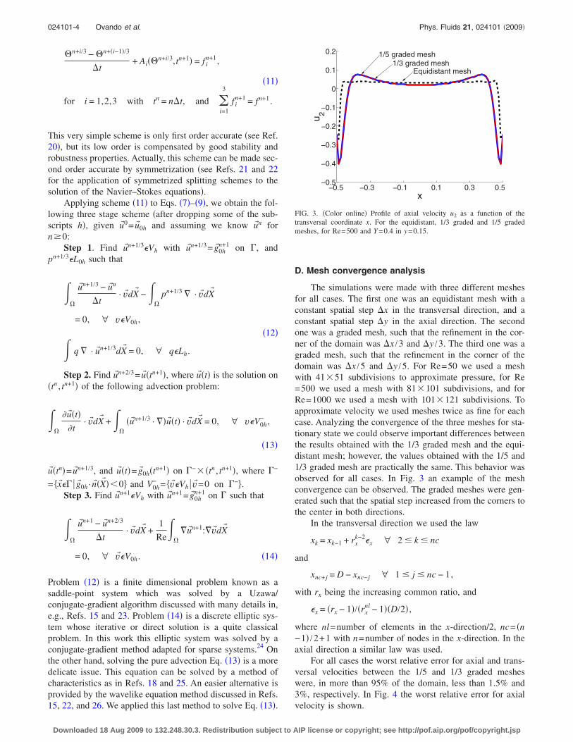
D. Mesh convergence analysis
The simulations were made with three different meshesfor all cases. The first one was an equidistant mesh with aconstant spatial step �x in the transversal direction, and aconstant spatial step �y in the axial direction. The secondone was a graded mesh, such that the refinement in the cor-ner of the domain was �x /3 and �y /3. The third one was agraded mesh, such that the refinement in the corner of thedomain was �x /5 and �y /5. For Re=50 we used a meshwith 41�51 subdivisions to approximate pressure, for Re=500 we used a mesh with 81�101 subdivisions, and forRe=1000 we used a mesh with 101�121 subdivisions. Toapproximate velocity we used meshes twice as fine for eachcase. Analyzing the convergence of the three meshes for sta-tionary state we could observe important differences betweenthe results obtained with the 1/3 graded mesh and the equi-distant mesh; however, the values obtained with the 1/5 and1/3 graded mesh are practically the same. This behavior wasobserved for all cases. In Fig. 3 an example of the meshconvergence can be observed. The graded meshes were gen-erated such that the spatial step increased from the corners tothe center in both directions.
In the transversal direction we used the law
xk = xk−1 + rxk−2x ∀ 2 � k � nc
and
xnc+j = D − xnc−j ∀ 1 � j � nc − 1,
with rx being the increasing common ratio, and
x = �rx − 1�/�rxnl − 1��D/2� ,
where nl=number of elements in the x-direction/2, nc= �n−1� /2+1 with n=number of nodes in the x-direction. In theaxial direction a similar law was used.
For all cases the worst relative error for axial and trans-versal velocities between the 1/5 and 1/3 graded mesheswere, in more than 95% of the domain, less than 1.5% and3%, respectively. In Fig. 4 the worst relative error for axialvelocity is shown.
−0.5 −0.3 −0.1 0.1 0.3 0.5−0.5
−0.4
−0.3
−0.2
−0.1
0
0.1
0.2
x
u 2
Equidistant mesh1/3 graded mesh
1/5 graded mesh
FIG. 3. �Color online� Profile of axial velocity u2 as a function of thetransversal coordinate x. For the equidistant, 1/3 graded and 1/5 gradedmeshes, for Re=500 and Y =0.4 in y=0.15.
024101-4 Ovando et al. Phys. Fluids 21, 024101 �2009�
Downloaded 18 Aug 2009 to 132.248.30.3. Redistribution subject to AIP license or copyright; see http://pof.aip.org/pof/copyright.jsp
IV. RESULTS
A. Overview
To initiate the study of the vortex formation in the cavitywith oscillating walls, simulations for nine cases were donefor Re=VwD /�=50, 500, 1000, and Y =0.2, 0.4, 0.8. Wecharacterize the flows by describing the velocity and vortic-ity fields and vortex cores. The results reported display thelong-term behavior in the sense that the transient effects dueto initial conditions have died out. The vortex cores wereobtained by applying the Jeong–Hussain criterion,27 whichdefines a vortex in an incompressible flow in terms of theeigenvalues of the tensor S2+A2, where S and A are, respec-tively, the symmetric and antisymmetric parts of the velocitygradient tensor. In planar flow, a vortex core is defined as thearea where the eigenvalue of S2+A2 is negative.
As expected from the governing equations and boundaryconditions, the velocity fields and, consequently, the vortexcores for low Re and Y display axial and cyclic symmetries,defined as follows:
�a� axial symmetry
u1�x,y,�� = − u1�− x,y,�� ,
u2�x,y,�� = u2�− x,y,��;
�b� cyclic symmetry
u1�x,y,�� = u1�x,− y,� + �� ,
u2�x,y,�� = − u2�x,− y,� + �� .
In fact, among the first nine simulated cases, only axial sym-metry is lost for Re=1000 and Y =0.8.
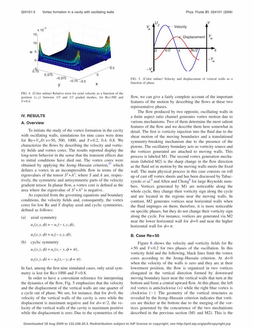
In order to have a convenient reference for interpretingthe dynamics of the flow, Fig. 5 emphasizes that the velocityand the displacement of the vertical walls are one quarter ofa cycle out of phase. We see, for instance, that for �=0, thevelocity of the vertical walls of the cavity is zero while thedisplacement is maximum negative and for �=� /2, the ve-locity of the vertical walls of the cavity is maximum positivewhile the displacement is zero. Due to the symmetries of the
flow, we can give a fairly complete account of the importantfeatures of the motion by describing the flows at these tworepresentative phases.
The flow produced by two opposite, oscillating walls ina finite aspect ratio channel generates vortex motion due tovarious mechanisms. Two of them determine the most salientfeatures of the flow and we describe them here somewhat indetail. The first is vorticity injection into the fluid due to theshear motion of the moving boundaries and a translationalsymmetry-breaking mechanism due to the presence of thepistons. The oscillatory boundary acts as vorticity source andthe vortices generated are attached to moving walls. Thisprocess is labeled M1. The second vortex generation mecha-nism �labeled M2� is the sharp change in the flow directionas the fluid set in motion by the moving walls meets the fixedwall. The main physical process in this case consists on rollup of cast off vortex sheets and has been discussed by Tabac-zynski et al.4 and Allen and Chong8 for large Reynolds num-bers. Vortices generated by M1 are noticeable along thewhole cycle, they change their vorticity sign along the cycleand are located in the regions near the moving walls. Incontrast, M2 generates vortices near horizontal walls whenthe fluid impinges on them; therefore, it is more noticeableon specific phases, but they do not change their vorticity signalong the cycle. For instance, vortices are generated via M2near the lower horizontal wall for �=0 and near the higherhorizontal wall for �=�.
B. Case Re=50
Figure 6 shows the velocity and vorticity fields for Re=50 and Y =0.2 for two phases of the oscillation. In thisvorticity field and the following, black lines limit the vortexcores according to the Jeong–Hussain criterion. At �=0when the velocity of the walls is zero and they are at theirlowermost position, the flow is organized in two vorticeselongated in the vertical direction formed by downwardmoving boundary layer near the vertical walls that turn at thebottom and form a central upward flow. At this phase, the leftred vortex is anticlockwise �+� while the right blue vortex isclockwise ���. The geometry of the vortical structures asrevealed by the Jeong–Hussain criterion indicates that vorti-ces are thicker at the bottom due to the merging of the vor-tices generated by the concurrence of the two mechanismsdescribed in the previous section �M1 and M2�. This is the
−0.5
0
0.5
−0.75−0.375
0.3750.75−5
0
5
10
15x 10
−3
xy
e
FIG. 4. �Color online� Relative error for axial velocity as a function of theposition �x ,y� between 1/5 and 1/3 graded meshes, for Re=500 andY =0.4.
0 π/2 π 3π/2 φ
U2
YV
w
−Vw
Yw
−Yw
Velocity
Displacement
FIG. 5. �Color online� Velocity and displacement of vertical walls as afunction of phase.
024101-5 Vortex formation in a cavity with oscillating walls Phys. Fluids 21, 024101 �2009�
Downloaded 18 Aug 2009 to 132.248.30.3. Redistribution subject to AIP license or copyright; see http://pof.aip.org/pof/copyright.jsp
region of larger vorticity. This flow originates half saddlecritical points at the centers of the horizontal walls. Twoelliptical points are identified at x= �0.32, y=0 indicatingthe center of the vortices.
The flow at �=� /2 displays thin ascending regions nearthe moving walls which, at this phase of the cycle, havemaximum positive velocity. The returning, descending flowsare confined to regions close to the vertical walls and in thecore of the container, the fluid is practically stagnant, at thisphase the left vortex is clockwise ��� while the right vortexis anticlockwise �+�. The vortices generated by the flow atthis phase display an almost constant thickness and are lo-cated close to the moving walls, as shown in Fig. 6. Thevortices at this phase of the cycle are generated by mecha-nism M1. As expected, the vortices are located around ellip-tic points and away from saddle points. The vertical exten-sion of the vortices remains almost constant through thecycle, but the thickness pulsates with maxima �minima� at�=0, � ��=� /2, 3� /2�. The effect of increasing the am-plitude of the wall displacement �Y� is illustrated in Fig. 7,where velocity and vorticity fields and vortices are shown forRe=50 and Y =0.4. The most notable difference between theflows in Figs. 6 and 7 is that the thickness of the vorticalstructure increases as the amplitude increases. This is ex-pected since the moving walls constitute a vorticity source.When the amplitude of the oscillation is further increased toY =0.8, the thickening of the vortices continues and in thiscase, the vortices cover at least 50% of the total area. This isillustrated in Fig. 8 where the velocity and vorticity fieldsand vortex cores are shown.
FIG. 6. �Color online� Upper row: velocity fields. Lower row: vorticityfields and vortex cores, for �=0 and �=� /2 with Re=50 and Y =0.2. FIG. 7. �Color online� Upper row: velocity fields. Lower row: vorticity
fields and vortex cores, for �=0 and �=� /2 with Re=50 and Y =0.4.
FIG. 8. �Color online� Upper row: velocity fields. Lower row: vorticityfields and vortex cores, for �=0 and �=� /2 with Re=50 and Y =0.8.
024101-6 Ovando et al. Phys. Fluids 21, 024101 �2009�
Downloaded 18 Aug 2009 to 132.248.30.3. Redistribution subject to AIP license or copyright; see http://pof.aip.org/pof/copyright.jsp
In order to assess the influence of the top and bottomfixed walls on the dynamics of the flow, we analyze theprofile of the axial velocity u2 as a function of the transversalcoordinate for several phases in one cycle. For reference, werecall that the velocity profile as a function of the transversal
coordinate in an infinitely long channel with oscillating walls�second Stokes problem, see Ref. 28� is given by
u�x,t� = BVw cos �t + CVw sin �t , �15�
where
B = � cos l� cos x� cosh l� cosh x� + sin l� sin x� sinh l� sinh x�
�cos l� cosh l��2 + �sin l� sinh l��2 �and
C = � cos l� sin x� cosh l� sinh x� − sin l� cos x� sinh l� cosh x�
�cos l� cosh l��2 + �sin l� sinh l��2 � ,
where l=D /2 and the parameter � is the inverse of theStokes penetration depth and is defined by
� =� �
2�,
where � is the angular velocity and � is the kinematic vis-cosity. This velocity profile is shown in Fig. 9 taking Re=50 and Y =0.2. It is seen that for these conditions, theStokes penetration depth is smaller than the semidistancebetween the channel walls ��D /2� /��=5.5� and for positive�or negative� x, the envelopes are monotonous functions ofthis coordinate. The flow in the region near the center of thechannel �x�0� is practically stagnant at all times. Also, itshould be noted that for an infinite channel, the x-averagedinstantaneous velocity is not zero, while for the finite aspectratio channel, the x-averaged instantaneous velocity must bezero at all times due to presence of the horizontal walls.
The equivalent velocity profiles obtained at y=0 for thechannel with finite aspect ratio �H /D=1.5� are shown in Fig.10. The envelopes are not monotonous functions of x. Incontrast to the infinite aspect ratio channel, the flow at thecenter of the channel is stagnant only for specific phases inthe cycle. In the region close to the lateral walls ����, thevelocity profiles for infinite and finite aspect ratios coincide,indicating that at y=0, the presence of the horizontal walls isfelt only in the core of the channel. When the amplitude ofthe oscillatory motion of the walls is increased to Y =0.8, thefeatures just described are amplified as can be observed inFig. 11. Another useful parameter to describe the effect ofthe presence of the horizontal walls on the dynamics of theoscillatory flow is the phase shift of the fluid oscillation as afunction of the distance to the vertical wall �. As is wellknown, in the second Stokes problem, the fluid oscillateswith a phase shift linearly proportional to the distance to thewall. The proportionality constant is �. For the infinite chan-nel, the phase shift follows from Eq. �15� and is
−0.5 0 0.5−1
−0.5
0
0.5
1
x
u 2
φ=0
φ=π
φ=π/2
FIG. 9. �Color online� Axial velocity u2 as a function of the transversalcoordinate x for an infinite channel �Eq. �15�� with Re=50 and Y =0.2. Thephase interval between profiles is � /6.
−0.5 0 0.5−1
−0.5
0
0.5
1
x
u 2
φ=π/2
φ=π
φ=0
FIG. 10. �Color online� Axial velocity u2 as a function of the transversalcoordinate x for a channel with aspect ratio �H /D=1.5�, Re=50, and Y=0.2. For all profiles, y=0. The phase interval between profiles is � /6.
024101-7 Vortex formation in a cavity with oscillating walls Phys. Fluids 21, 024101 �2009�
Downloaded 18 Aug 2009 to 132.248.30.3. Redistribution subject to AIP license or copyright; see http://pof.aip.org/pof/copyright.jsp
� = arctan� cos l� sin x� cosh l� sinh x� − sin l� cos x� sinh l� cosh x�
cos l� cos x� cosh l� cosh x� + sin l� sin x� sinh l� sinh x�� . �16�
In Fig. 12, ��� is shown as a function of the transversalcoordinate for y=0 and Re=50. Two cases are displayed, Y=0.2 and 0.8; the lines are for an infinite long channel �Eq.�16��, while symbols represent finite aspect channel results.It is found that � for infinite and finite aspect ratio channelscoincide within the Stokes penetration depth which is 18%and 35% of the semidiameter, but then the presence of thehorizontal walls generates a steep increase up to approxi-mately one quarter of the channel width where a plateau isreached. Even though the wall oscillation amplitude of thetwo cases analyzed differs by a factor of four, the maxima �reached at x=0, are only 1.34� and 1.22�, respectively. Thisobservation contrasts with the corresponding values of1.875� and 0.875� for the infinite channel. Figures 9, 10,and 12 indicate that, in a relatively small region near thechannel center �y=0� and close to the oscillatory walls �x= �0.5�, the presence of the horizontal walls does not have amajor influence on the flow, but elsewhere in the cavity thelimiting walls are determinant.
C. Case Re=500
Figures 13–15 show the velocity and vorticity fields, andvortex cores for Re=500, Y =0.2, 0.4, and 0.8, for twophases of the oscillation. The vortex distribution along thecycle is more complex than that for Re=50. The vorticesgenerated by M1 are thinner that those observed in Sec.IV C. The vortices generated by M2 are separated from thosegenerated by M1. They are formed initially in the regionsnext to the moving walls as these meet the upper fixed walls�bottom fixed walls� at the phase of maximum wall velocity�=� /2 ��=3� /2�. The maximum vorticity is seen to occur
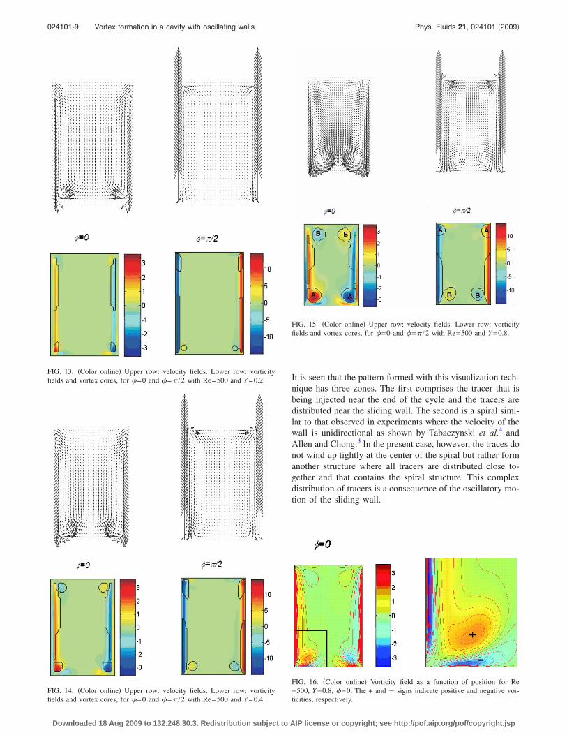
at �=0 ��=�� when the velocity of the sliding walls is zero.These vortices are labeled “A” in Fig. 15 and were describedand interpreted by Tabaczynski et al.4 For Y =0.2, the vorti-ces dissipate at the core of the cavity, but for Y =0.4 and 0.8they persist up to the phase �=� /2 ��=3� /2� as indicatedby label “B” in Fig. 15. Eventually, they dissipate in the coreof the cavity. The presence of these structures at phaseswhere the sliding walls move away from the fixed walls wasnot noticed in the visualizations made by Tabaczynski et al.4
The separation of the vortices formed by mechanism M2from the fixed wall that is observed on the flows described inthis and Sec. III, can be interpreted in terms of general con-cepts of interactions of individual vortices and walls. It hasbeen found that as a vortex approaches a wall perpendicularto its direction of motion, a region with opposite vorticity isformed between its core and the wall. See, for instance,Walker et al.29 and Allen and Chong8 for experimental ob-servations and Peace and Riley30 for numerical calculations.In our simulations, this effect is present at the lower fixedwall for �=0 as can be seen from Fig. 16 where the vorticityfield is plotted as a function of position for Re=500, Y=0.8. As the vortices moving downward approach the hori-zontal wall, a secondary vorticity region with opposite signis formed between the vortex core and the fixed wall, induc-ing the vortex to move away from the fixed wall. Given thatthe driving force of the flow is oscillatory, the formation ofthe vortices and the induced secondary vorticity regions areperiodic too.
The pattern observed by the visualization of vorticesgenerated by the oscillatory flow for Re=500, Y =0.8, isshown in Fig. 17. The streak lines in this figure simulate atracer injected at approximately one-tenth of the height �y=−0.610� and −0.450�x�−0.423. Injection starts when thevelocity is maximum positive and displacement is zero ��=� /2�, and it lasts throughout the one full cycle simulation.
−0.5 0 0.5−1
−0.5
0
0.5
1
x
u 2
φ=π/2
φ=π
φ=0
FIG. 11. �Color online� Axial velocity u2 as a function of the transversalcoordinate x for a channel with aspect ratio �H /D=1.5�, Re=50, and Y=0.8. For all profiles, y=0. The phase interval between profiles is � /6.
0x
−0.5 0.5
π/2
π
3π/2
2π
ψ
Y=0.2
Y=0.8
0
FIG. 12. �Color online� Relative phase between oscillating walls and thefluid axial velocity � as a function of the transversal coordinate x. Re=50and y=0.
024101-8 Ovando et al. Phys. Fluids 21, 024101 �2009�
Downloaded 18 Aug 2009 to 132.248.30.3. Redistribution subject to AIP license or copyright; see http://pof.aip.org/pof/copyright.jsp
It is seen that the pattern formed with this visualization tech-nique has three zones. The first comprises the tracer that isbeing injected near the end of the cycle and the tracers aredistributed near the sliding wall. The second is a spiral simi-lar to that observed in experiments where the velocity of thewall is unidirectional as shown by Tabaczynski et al.4 andAllen and Chong.8 In the present case, however, the traces donot wind up tightly at the center of the spiral but rather formanother structure where all tracers are distributed close to-gether and that contains the spiral structure. This complexdistribution of tracers is a consequence of the oscillatory mo-tion of the sliding wall.
FIG. 13. �Color online� Upper row: velocity fields. Lower row: vorticityfields and vortex cores, for �=0 and �=� /2 with Re=500 and Y =0.2.
FIG. 14. �Color online� Upper row: velocity fields. Lower row: vorticityfields and vortex cores, for �=0 and �=� /2 with Re=500 and Y =0.4.
FIG. 15. �Color online� Upper row: velocity fields. Lower row: vorticityfields and vortex cores, for �=0 and �=� /2 with Re=500 and Y =0.8.
FIG. 16. �Color online� Vorticity field as a function of position for Re=500, Y =0.8, �=0. The + and � signs indicate positive and negative vor-ticities, respectively.
024101-9 Vortex formation in a cavity with oscillating walls Phys. Fluids 21, 024101 �2009�
Downloaded 18 Aug 2009 to 132.248.30.3. Redistribution subject to AIP license or copyright; see http://pof.aip.org/pof/copyright.jsp
D. Case Re=1000
Figures 18 and 19 show the velocity and vorticity fields,and vortex cores for Y =0.2 and 0.4, for two phases of theoscillation. The vortex distribution and evolution are similarto those of Re=500, only the vortical structures are thinnerand confined to the regions near the walls. Most of the chan-nel is vortex free all along the cycle. As the amplitude of thedisplacement is increased, the area occupied by the vortices
is enlarged, but the qualitative properties of the flow are thesame. See Fig. 19. In all cases presented up to this point, theflow distributions display the axial and cyclic symmetriesdefined at the beginning of Sec. IV. When the amplitude ofthe wall oscillation is increased to Y =0.8, the symmetryaround x=0 is lost. Figure 20 shows the velocity and vortic-ity fields, and vortex cores for Y =0.8, for two phases of theoscillation. With this set of parameters, the flow is not axialsymmetric anymore but it conserves cycle symmetry. At �=0, the right and left vortices generated as the sliding wallsapproach the bottom wall and those near the upper wall arenot the same size. This imbalance generates a cross flow thatmoves from the bottom right corner to the upper left cornerof the cavity forming a large vortex rotating clockwise. Seeupper left panel in Fig. 20. The distribution of vorticesshown in the lower left panel of Fig. 20 confirms the previ-ous observations by displaying a large structure near the cen-ter of the cavity. It is instructive to compare these figureswith the corresponding for Re=500 given in Fig. 15 whichcan be interpreted as an approximate symmetric version ofFig. 20 where the cross flow and the central vortex are ab-sent. The flow structure at �=� /2 �right-hand side panels ofFig. 20� also includes a large central vortex and is similar tothat of �=0. Left upward and right downward flows aremore intense. The governing equations and boundary condi-tions are symmetric with respect to the x=0 axis, therefore, avelocity and pressure fields of the form
FIG. 17. Streak lines for Re=500, Y =0.8 to simulate flow visualization.Tracer injection starts at �=� /2 and continues for one cycle. Coordinatesfor tracer injection are x=−0.450, �0.446, �0.442, �0.439, �0.435,�0.431, �0.427, and �0.423, y=−0.610.
FIG. 18. �Color online� Upper row: velocity fields. Lower row: vorticityfields and vortex cores, for �=0 and �=� /2 with Re=1000 and Y =0.2.
FIG. 19. �Color online� Upper row: velocity fields. Lower row: vorticityfields and vortex cores, for �=0 and �=� /2 with Re=1000 and Y =0.4.
024101-10 Ovando et al. Phys. Fluids 21, 024101 �2009�
Downloaded 18 Aug 2009 to 132.248.30.3. Redistribution subject to AIP license or copyright; see http://pof.aip.org/pof/copyright.jsp
u1�x,y,�� = − u1��− x,y,��, u2�x,y,�� = u2
��− x,y,�� ,
�17�p�x,y,�� = p��− x,y,�� ,
where u1�, u2
�, and p� are the velocity and pressure distribu-tions of the flow described in the previous paragraph, andillustrated in Fig. 20, is also a solution. We conclude thenthat there is a qualitative change in the dynamical behaviorfeatured by the breaking of the axial symmetry, which forRe=1000 occurs between 0.4�Y �0.8, and for Y =0.8, itoccurs within 500�Re�1000. We analyze this breakdownin Sec. IV E.
Figure 21 shows the profile of axial velocity u2 for achannel with infinite length as a function of the transversalcoordinate x. In this figure, Re=1000 and Y =0.2. The Stokespenetration depth is smaller and a thinner boundary layerforms near the wall. The core of the channel is motionless.The corresponding plots of axial velocity for a channel withaspect ratio 1.5 and Re=1000 are displayed in Figs. 22 and23 for Y =0.2 and 0.8, respectively. The plots in these figuresare obtained for y=0. The properties of the velocity profilesfor Y =0.2 �Fig. 22� are similar to those described for thecases of Sec. IV B, namely, the profiles for an infinite chan-nel and a finite aspect ratio channel are indistinguishablenear the walls ��D /2� /��=25�. The boundary layer is thinnerthan that obtained for smaller Reynolds numbers and theflow in the core is not stagnant but ascends or descends atdifferent phases of the oscillation. Also, it was found �but not
shown in figures� that, as discussed in Sec. IV B, the distor-tion due to the presence of the horizontal walls in the centralpart of the cavity increase as Y increases.
For Y =0.8 we observe notable differences in the velocitydistributions with respect to the infinite channel behavior dueto the breaking of the axial symmetry, as is shown in Fig. 23.It is found that a clockwise vortex is permanently present inthe cavity, deflecting slightly upward the velocity traces onthe left side and downward near the right side. Velocitiesclose to the moving walls ��D /2� /��=12.5� are symmetric,but in the core they are distorted due to the vortical globalmotion which has always the same direction of rotation. Ascommented previously, a second solution also exists inwhich the core vortex rotates anticlockwise.
E. Axial symmetry breakdown analysis
To study the axial symmetry breakdown of the steadystate, we consider Y =0.8 and take Re as the bifurcation pa-rameter. The nonlinear criticality of the axial symmetry bi-furcation is determined by examining the variation with Reof a measure related to the energy �squared amplitude� of theasymmetry of the flow.10 Here, this measure is defined as
0 0.1 0.2 0.3 0.4 0.5−1
−0.5
0
0.5
1
x
u 2
φ=π/2
φ=π
φ=0
FIG. 22. �Color online� Axial velocity u2 as a function of the transversalcoordinate x for a channel with aspect ratio �H /D=1.5�, Re=1000, and Y=0.2. For all profiles, y=0. Phase intervals between profiles are ��=� /6.
FIG. 20. �Color online� Upper row: velocity fields. Lower row: vorticityfields and vortex cores, for �=0 and �=� /2 with Re=1000 and Y =0.8.
0 0.1 0.2 0.3 0.4 0.5−1
−0.5
0
0.5
1
x
u 2
φ=π/2
φ=π
φ=0
FIG. 21. �Color online� Axial velocity u2 as a function of the transversalcoordinate x for an infinite channel �Eq. �15�� with Re=1000 and Y =0.2.Phase intervals between profiles are ��=� /6.
024101-11 Vortex formation in a cavity with oscillating walls Phys. Fluids 21, 024101 �2009�
Downloaded 18 Aug 2009 to 132.248.30.3. Redistribution subject to AIP license or copyright; see http://pof.aip.org/pof/copyright.jsp
Q = �−H/2
H/2 �−��
��
u12�x = 0,y,t�dtdy . �18�
Clearly, Q is zero for symmetric flows. It is convenient toremark that the reported Q was calculated after a sufficientnumber of cycles have passed to guarantee that the differ-ence between their values of subsequent cycles is less than1%. For most cases this requires more than 300 cycles. Fig-ure 24 shows Q as a function of Re, symbols are simulationresults, and the line is the linear fit to the first four pointsdifferent from zero. The critical Reynolds number, calculatedby extrapolating the linear fit, is Rec=669.1�0.5. This math-ematical relationship between Q and Re near Rec indicatesthat the symmetry is broken through a supercritical pitchforkbifurcation.
V. DISCUSSION AND CONCLUSIONS
A numerical solution of the Navier–Stokes equations,using finite element and an operator splitting scheme, havebeen obtained for simulating the flow in a cavity with verti-cal walls simultaneously oscillating. For the range of oscil-
lation amplitude Y and Reynolds number Re explored, wehave found that the main feature of the flow is the formationof vortices with cyclic symmetry. For low values of Y andRe, the vortices also present symmetry with respect to thevertical axis dividing the cavity in two sides. In asymmetricflows, the unbalance between the vortices on each side of themidvertical line generates a vortex that occupies the centralpart of the cavity and preserves vorticity sign along thecycle. The vorticity sign of the central vortex depends oninitial conditions.
The vortex cores were identified using the Jeong–Hussain criterion. For a given Reynolds number, the areaoccupied by the vortex cores increases as Y increases. ForRe=50, the cores area represents approximately the 30%,45%, and 50% of the total area for Y =0.2, Y =0.4, and Y=0.8, respectively. For a fixed Y, the area decreases as theReynolds number increases. For Y =0.2, the area representsapproximately the 30%, 5%, and 4% of the total area forRe=50, Re=500, and Re=1000, respectively.
We have identified two basic mechanisms of vortex for-mation: The first is vorticity injection into the fluid due to theshear motion of the moving walls in the presence of the fixedwalls that provide a translational symmetry breaking �M1�.Note that both fixed walls break the translational symmetryregardless of whether they are up- or downstream of the flowand thus contribute to the formation of vortices. These vor-tices are elongated, aligned with the oscillatory walls withreturn regions near the fixed walls, and change their vorticitysign along the cycle. Their characteristic dimension in thetransversal direction is inversely proportional to the fre-quency of oscillation which, for fixed fluid and geometry,can be expressed in terms of the oscillatory Reynolds num-ber defined by R�=Re /Y =�D2 /�. Note, for instance, thatthe width of the elongated vortex cores of figures �Y=0.2, Re=500� and �Y =0.4, Re=1000� at �=0, whichhave the same oscillatory Reynolds number, are equal. Thesecond vortex formation mechanism is the abrupt change inthe flow direction as the fluid meets the downstream fixedwall �M2�. This effect occurs for oscillatory walls as well asfor walls moving with constant velocity and is a consequenceof boundary layer being scraped off by the fixed wall. Sincethe flow under analysis is oscillatory, the vortex formation bythis mechanism is strongly dependent on the phase of thecycle. Vortices are formed at the bottom �top� fixed wall at�=0 ��� when the flow moves against the wall. The vorticesformed by mechanism M2 conserve their vorticity sign andremain at phases where the sliding walls move away fromthe fixed wall, but detach from the corresponding movingwall. We found that for Reynolds number greater than 500the detach of vortices by mechanism M2 occurs, this agreeswith the critical Reynolds number ��450� for the vortex ringformation obtained by Hughes and Gerrard31 and with theReynolds number ��400� for the roll up of vortices obtainedby Allen and Chong.8
The streak line topology is difficult to analyze since forthis time-dependent flow, the trace distributions depend onthe position where the traces are released, the phase in thecycle when this occurs, and the duration. We have just
−0.5 0 0.5−1
−0.5
0
0.5
1
x
u 2
φ=0
φ=π
φ=π/2
FIG. 23. �Color online� Axial velocity u2 as a function of the transversalcoordinate x for a channel with aspect ratio �H /D=1.5�, Re=1000, and Y=0.8. For all profiles, y=0. Phase intervals between profiles are ��=� /6.
660 680 700 720 7400
1
2
3
4
5
6
7
8x 10
−4
Re
Q
Rec
FIG. 24. Q as a function of Re, symbols are simulation results and the lineis the linear fit to the first four points different from zero. The criticalReynolds number is Rec=669.1�0.5.
024101-12 Ovando et al. Phys. Fluids 21, 024101 �2009�
Downloaded 18 Aug 2009 to 132.248.30.3. Redistribution subject to AIP license or copyright; see http://pof.aip.org/pof/copyright.jsp
illustrated one case to highlight the fact that these featuresmight be interesting in the context of mixing with oscillatoryflows.
All the analyzed cases display cyclic symmetry and, incontrast with all other cases analyzed, for Y =0.8 and Re=1000, the distribution of vortices is not symmetric withrespect to the vertical axis. This is due to the formation of alarge vortex in the center of the cavity rotating in the samedirection in the whole cycle.
The breakdown of the axial symmetry was studied for afixed value of the oscillation amplitude, Y =0.8, taking Re asthe bifurcation parameter. The results indicate that the sym-metry is broken through a supercritical pitchfork bifurcation.
Our results can also be described in terms of the Stokesparameter St=�H2 /�. The cases explored in the present in-vestigation are Re=50: St=10,20,40; Re=500: St=100,200,400, and Re=1000: St=200,400,800. The small-est values of the Stokes parameter correspond to the largestvalues of Y. The nonsymmetric flow described in detail cor-responds to Re=1000, St=200. It is interesting to observethat all cases studied fall in the region where stable, 2D flowis predicted by the theory for 3D instabilities of the 2D flowin a rectangular cavity driven by the simple harmonic oscil-lation of one wall presented by Blackburn and Lopez,10 butthe case Re=1000, St=200 is closest to the neutral stabilityline. The model presented here considers only 2D flows andtherefore is unable to determine whether the 2D instabilitywould appear in a real system before a 3D instability devel-ops. In order to address this point, a 3D model of the flowwould be required, but unfortunately this is beyond the scopeof the present investigation.
Although the application of the present study is limiteddue to the fact that it is made for a 2D flow, it is consideredthat the time-dependent distribution of vortices is potentiallyuseful for understanding transport properties in oscillatoryflows.
ACKNOWLEDGMENTS
The authors thank Francisco Mandujano and RaúlRechtman for fruitful discussions and suggestions. Partialeconomic support from the DGAPA-UNAM and CONACyTunder Project Nos. IN104702-2 and U41347-F, respectively,was acknowledged. G.O. thanks CONACyT for a postgradu-ate scholarship.
1D. Lee and S. Hochgreb, “Rapid compression machines: Heat transfer andsuppression of corner vortex,” Combust. Flame 114, 531 �1998�.
2J. M. Lopez and A. Hirsa, “Oscillatory driven cavity with an air/waterinterface and an insoluble monolayer: Surface viscosity effects,” J. ColloidInterface Sci. 242, 1 �2001�.
3V. O’Brien, “Unsteady separation phenomena in a two-dimensional cav-ity,” AIAA J. 13, 415 �1975�.
4R. J. Tabaczynski, D. P. Hoult, and J. C. Keck, “High Reynolds numberflow in a moving corner,” J. Fluid Mech. 42, 249 �1970�.
5G. I. Taylor, “On scraping viscous fluid from a plane surface,” in TheScientific Papers of Sir Geoffrey Ingran Taylor, edited by G. K. Batchelor�Cambridge University Press, Cambridge, 1971�, Vol. IV, pp. 410–413.
6C. Hancock, E. Lewis, and H. K. Moffatt, “Effects of inertia in forcedcorner flows,” J. Fluid Mech. 112, 315 �1981�.
7G. K. Batchelor, An Introduction to Fluid Dynamics �Cambridge Univer-sity Press, Cambridge, 1967�.
8J. J. Allen and M. S. Chong, “Vortex formation in front of a piston movingthrough a cylinder,” J. Fluid Mech. 416, 1 �2000�.
9M. J. Vogel, A. H. Hirsa, and J. M. Lopez, “Spatio-temporal dynamics ofa periodically driven cavity flow,” J. Fluid Mech. 478, 197 �2003�.
10H. M. Blackburn and J. M. Lopez, “The onset of three-dimensional stand-ing and modulated travelling waves in a periodically driven cavity flow,”J. Fluid Mech. 497, 289 �2003�.
11J. J. F. Leung, A. H. Hirsa, H. M. Blackburn, F. Marquez, and J. M. Lopez,“Three-dimensional modes in a periodically driven elongated cavity,”Phys. Rev. E 71, 026305 �2005�.
12R. Temam, Theory and Numerical Analysis of the Navier–Stokes Equa-tions �North-Holland, Amsterdam, 1977�.
13V. Girault and P. A. Raviart, Finite Element Methods for the Navier–StokesEquations: Theory and Algorithms �Springer-Verlag, Berlin, 1986�.
14M. D. Gunzburger, Finite Element Methods for Viscous IncompressibleFlows �Academic, Boston, 1989�.
15R. Glowinski, “Numerical methods for fluids, part 3,” in Handbook ofNumerical Analysis, Vol. IX, edited by P. G. Garlet and J. L. Lions �North-Holland, Amsterdam, 2003�.
16M. Bercovier and O. Pironneau, “Error estimates for the finite elementsolution of the Stokes problem in the primitive variables,” Numer. Math.33, 211 �1979�.
17A. Chorin, “Numerical study of slightly viscous flow,” J. Fluid Mech. 57,785 �1973�.
18R. Glowinski and O. Pironneau, “Finite element methods for the Navier–Stokes equations,” Annu. Rev. Fluid Mech. 24, 167 �1992�.
19S. Turek, Efficient Solvers for Incompressible Flow Problems: An Algo-rithmic and Computational Approach �Springer-Verlag, Berlin, 1999�.
20G. I. Marechuk, “Splitting and alternate direction methods,” in Handbookof Numerical Analysis, edited by P. G. Garlet and J. L. Lions �North-Holland, Amsterdam, 1990�, Vol. 1, pp. 197–462.
21J. T. Beale and A. Majda, “Rates of convergence for viscous splitting ofthe Navier–Stokes equations,” Math. Comput. 37, 243 �1981�.
22E. J. Dean and R. Glowinski, “A wave equation approach to the numericalsolution of the Navier–Stokes equations for incompressible viscous flow,”C. R. Acad. Sci., Ser. I: Math. 325, 783 �1997�.
23R. Glowinski and P. Le Tallec, Augmented Lagrangian and Operator-Splitting Methods in Nonlinear Mechanics �SIAM, Philadelphia, 1989�.
24W. H. Press, S. A. Teukolsky, W. T. Vetterling, and B. P. Flannery, Nu-merical Recipes in C�� �Cambridge University Press, Cambridge, 2002�.
25O. Pironneau, Finite Element Methods for Fluids �Wiley, Chichester,1989�.
26E. J. Dean, R. Glowinski, and T. W. Pan, “A wave equation approach tothe numerical simulation of incompressible viscous fluid flow modeled bythe Navier–Stokes equations,” in Mathematical and Numerical Aspects ofWave Propagation, edited by J. A. de Santo �SIAM, Philadelphia, 1998�,pp. 65–74.
27J. Jeong and F. Hussain, “On the identification of a vortex,” J. Fluid Mech.285, 69 �1995�.
28I. G. Currie, Fundamental Mechanics of Fluids �McGraw-Hill, New York,1974�.
29J. Walker, C. Smith, A. Cerra, and T. Doligalski, “The impact of a vortexring on a wall,” J. Fluid Mech. 181, 99 �1987�.
30A. J. Peace and N. Riley, “A viscous vortex pair in ground effect,” J. FluidMech. 129, 409 �1983�.
31M. D. Hughes and J. H. Gerrard, “The stability of unsteady axisymmetricincompressible pipe flow close to a piston. Part 2. Experimental investi-gation and comparison with computation,” J. Fluid Mech. 50, 645 �1971�.
024101-13 Vortex formation in a cavity with oscillating walls Phys. Fluids 21, 024101 �2009�
Downloaded 18 Aug 2009 to 132.248.30.3. Redistribution subject to AIP license or copyright; see http://pof.aip.org/pof/copyright.jsp


![Finite-Core Vortex Array Model of the Wake of a ...7)_AIAA J_Naguib+Vit… · theory of oscillating airfoils [7,8]. Nevertheless, ... Koochesfahani [10] showed that in all pure-harmonic-oscillation](https://static.documents.pub/doc/80x56/6070630a29767910a55b286b/finite-core-vortex-array-model-of-the-wake-of-a-7aiaa-jnaguibvit-theory.jpg)


