510
Nokia Network Voyager for IPSO 4.0 Reference Guide Part No. N450000127 Rev 001 Published January 2006

Nokia Network Voyagerfor IPSO 4.0
Reference Guide
Part No. N450000127 Rev 001
Published January 2006

COPYRIGHT©2005 Nokia. All rights reserved.Rights reserved under the copyright laws of the United States.
RESTRICTED RIGHTS LEGENDUse, duplication, or disclosure by the United States Government is subject to restrictions as set forth in subparagraph (c)(1)(ii) of the Rights in Technical Data and Computer Software clause at DFARS 252.227-7013.
Notwithstanding any other license agreement that may pertain to, or accompany the delivery of, this computer software, the rights of the United States Government regarding its use, reproduction, and disclosure are as set forth in the Commercial Computer Software-Restricted Rights clause at FAR 52.227-19.
IMPORTANT NOTE TO USERS This software and hardware is provided by Nokia Inc. as is and any express or implied warranties, including, but not limited to, implied warranties of merchantability and fitness for a particular purpose are disclaimed. In no event shall Nokia, or its affiliates, subsidiaries or suppliers be liable for any direct, indirect, incidental, special, exemplary, or consequential damages (including, but not limited to, procurement of substitute goods or services; loss of use, data, or profits; or business interruption) however caused and on any theory of liability, whether in contract, strict liability, or tort (including negligence or otherwise) arising in any way out of the use of this software, even if advised of the possibility of such damage.
Nokia reserves the right to make changes without further notice to any products herein.
TRADEMARKS Nokia is a registered trademark of Nokia Corporation. Other products mentioned in this document are trademarks or registered trademarks of their respective holders.
050110
Nokia Contact InformationCorporate Headquarters
Web Site http://www.nokia.com
Telephone 1-888-477-4566 or 1-650-625-2000
2 Nokia Network Voyager for IPSO 4.0 Reference Guide

Regional Contact Information
Nokia Customer Support
Fax 1-650-691-2170
Mail Address
Nokia Inc.313 Fairchild DriveMountain View, California94043-2215 USA
Americas Nokia Inc.313 Fairchild DriveMountain View, CA 94043-2215USA
Tel: 1-877-997-9199Outside USA and Canada: +1 512-437-7089email: [email protected]
Europe, Middle East, and Africa
Nokia House, Summit AvenueSouthwood, FarnboroughHampshire GU14 ONG UK
Tel: UK: +44 161 601 8908Tel: France: +33 170 708 166email: [email protected]
Asia-Pacific 438B Alexandra Road#07-00 Alexandra TechnoparkSingapore 119968
Tel: +65 6588 3364email: [email protected]
Web Site: https://support.nokia.com/
Email: [email protected]
Americas Europe
Voice: 1-888-361-5030 or 1-613-271-6721
Voice: +44 (0) 125-286-8900
Fax: 1-613-271-8782 Fax: +44 (0) 125-286-5666
Asia-Pacific
Voice: +65-67232999
Fax: +65-67232897
050602
Nokia Network Voyager for IPSO 4.0 Reference Guide 3

4 Nokia Network Voyager for IPSO 4.0 Reference Guide

Contents
About the Nokia Network Voyager Reference Guide . . . . . . . . .19Conventions This Guide Uses . . . . . . . . . . . . . . . . . . . . . . . . . . . . 21
Notices . . . . . . . . . . . . . . . . . . . . . . . . . . . . . . . . . . . . . . . . . . . . 21Text Conventions . . . . . . . . . . . . . . . . . . . . . . . . . . . . . . . . . . . . 21Menu Items . . . . . . . . . . . . . . . . . . . . . . . . . . . . . . . . . . . . . . . . . 22
Related Documentation . . . . . . . . . . . . . . . . . . . . . . . . . . . . . . . . . 22
1 About Network Voyager . . . . . . . . . . . . . . . . . . . . . . . . . . . . . . . 23Software Overview . . . . . . . . . . . . . . . . . . . . . . . . . . . . . . . . . . . . . 23Logging In to Network Voyager . . . . . . . . . . . . . . . . . . . . . . . . . . . 24
Logging Off . . . . . . . . . . . . . . . . . . . . . . . . . . . . . . . . . . . . . . . . . 24Obtaining a Configuration Lock . . . . . . . . . . . . . . . . . . . . . . . . . . 25
Navigating in Network Voyager . . . . . . . . . . . . . . . . . . . . . . . . . . . 26Reloading Pages . . . . . . . . . . . . . . . . . . . . . . . . . . . . . . . . . . . . . 26Accessing Documentation and Help . . . . . . . . . . . . . . . . . . . . . . 26
Viewing Hardware and Software Information for Your System . . . 28
2 Configuring Interfaces . . . . . . . . . . . . . . . . . . . . . . . . . . . . . . . . 29Interface Overview . . . . . . . . . . . . . . . . . . . . . . . . . . . . . . . . . . . . . 29
IP2250 Management Ports . . . . . . . . . . . . . . . . . . . . . . . . . . . . . 30Configuring Network Devices . . . . . . . . . . . . . . . . . . . . . . . . . . . 30Configuring IP Addresses . . . . . . . . . . . . . . . . . . . . . . . . . . . . . . 31Interface Status . . . . . . . . . . . . . . . . . . . . . . . . . . . . . . . . . . . . . . 32
Nokia Network Voyager IPSO 4.0 Reference Guide 5

Configuring Tunnel Interfaces . . . . . . . . . . . . . . . . . . . . . . . . . . . 33Ethernet Interfaces. . . . . . . . . . . . . . . . . . . . . . . . . . . . . . . . . . . . . 34
Configuring Ethernet Interfaces. . . . . . . . . . . . . . . . . . . . . . . . . . 34Link Aggregation . . . . . . . . . . . . . . . . . . . . . . . . . . . . . . . . . . . . . . 35
Managing Link Aggregation Using SNMP. . . . . . . . . . . . . . . . . . 36Configuring Switches for Link Aggregation . . . . . . . . . . . . . . . . . 36Static Link Aggregation . . . . . . . . . . . . . . . . . . . . . . . . . . . . . . . . 37Link Aggregation on the IP2250 . . . . . . . . . . . . . . . . . . . . . . . . . 37Configuring Link Aggregation . . . . . . . . . . . . . . . . . . . . . . . . . . . 39
Gigabit Ethernet Interfaces . . . . . . . . . . . . . . . . . . . . . . . . . . . . . . 41Point-to-Point Over Ethernet . . . . . . . . . . . . . . . . . . . . . . . . . . . . . 43
Configuring PPPoE . . . . . . . . . . . . . . . . . . . . . . . . . . . . . . . . . . . 43Configuring MSS Clamping . . . . . . . . . . . . . . . . . . . . . . . . . . . . 46
Virtual LAN Interfaces . . . . . . . . . . . . . . . . . . . . . . . . . . . . . . . . . . 46FDDI Interfaces . . . . . . . . . . . . . . . . . . . . . . . . . . . . . . . . . . . . . . . 49ISDN Interfaces . . . . . . . . . . . . . . . . . . . . . . . . . . . . . . . . . . . . . . . 51
Configuring Calling Line-Identification Screening . . . . . . . . . . . . 56Dial-on-Demand Routing (DDR) Lists . . . . . . . . . . . . . . . . . . . . . 58ISDN Network Configuration Example . . . . . . . . . . . . . . . . . . . . 61ISDN Troubleshooting. . . . . . . . . . . . . . . . . . . . . . . . . . . . . . . . . 65
Token Ring Interfaces . . . . . . . . . . . . . . . . . . . . . . . . . . . . . . . . . . 71Token Ring Example. . . . . . . . . . . . . . . . . . . . . . . . . . . . . . . . . . 73
Point-to-Point Link over ATM . . . . . . . . . . . . . . . . . . . . . . . . . . . . . 75ATM Example . . . . . . . . . . . . . . . . . . . . . . . . . . . . . . . . . . . . . . . 78
IP over ATM (IPoA) . . . . . . . . . . . . . . . . . . . . . . . . . . . . . . . . . . . . 79IPoA Example . . . . . . . . . . . . . . . . . . . . . . . . . . . . . . . . . . . . . . . 82
Serial (V.35 and X.21) Interfaces . . . . . . . . . . . . . . . . . . . . . . . . . . 83Serial Interface Example . . . . . . . . . . . . . . . . . . . . . . . . . . . . . . . 87
T1(with Built-In CSU/DSU) Interfaces . . . . . . . . . . . . . . . . . . . . . . 88T1 Interface Example . . . . . . . . . . . . . . . . . . . . . . . . . . . . . . . . . 94
E1 (with Built-In CSU/DSU) Interfaces. . . . . . . . . . . . . . . . . . . . . . 96HSSI Interfaces . . . . . . . . . . . . . . . . . . . . . . . . . . . . . . . . . . . . . . 103Unnumbered Interfaces . . . . . . . . . . . . . . . . . . . . . . . . . . . . . . . . 107
6 Nokia Network Voyager IPSO 4.0 Reference Guide

Configuring Unnumbered Interfaces . . . . . . . . . . . . . . . . . . . . . 107Configuring OSPF over Unnumbered Interface . . . . . . . . . . . . 110OSPF over Unnumbered Interfaces Using Virtual Links . . . . . . 110
Cisco HDLC Protocol . . . . . . . . . . . . . . . . . . . . . . . . . . . . . . . . . . 111Point-to-Point Protocol . . . . . . . . . . . . . . . . . . . . . . . . . . . . . . . . . 112Frame Relay Protocol. . . . . . . . . . . . . . . . . . . . . . . . . . . . . . . . . . 114Loopback Interfaces . . . . . . . . . . . . . . . . . . . . . . . . . . . . . . . . . . . 117GRE Tunnels . . . . . . . . . . . . . . . . . . . . . . . . . . . . . . . . . . . . . . . . 118
Configuring GRE Tunnels . . . . . . . . . . . . . . . . . . . . . . . . . . . . . 118GRE Tunnel Example . . . . . . . . . . . . . . . . . . . . . . . . . . . . . . . . 121High Availability GRE Tunnels . . . . . . . . . . . . . . . . . . . . . . . . . 122HA GRE Tunnel Example . . . . . . . . . . . . . . . . . . . . . . . . . . . . . 122
DVMRP Tunnels. . . . . . . . . . . . . . . . . . . . . . . . . . . . . . . . . . . . . . 125DVMRP Tunnel Example . . . . . . . . . . . . . . . . . . . . . . . . . . . . . 126
ARP Table Entries . . . . . . . . . . . . . . . . . . . . . . . . . . . . . . . . . . . . 128Configuring ARP for ATM Interfaces . . . . . . . . . . . . . . . . . . . . . . 130Transparent Mode . . . . . . . . . . . . . . . . . . . . . . . . . . . . . . . . . . . . 132
Limitations . . . . . . . . . . . . . . . . . . . . . . . . . . . . . . . . . . . . . . . . . 132Transparent Mode Processing Details . . . . . . . . . . . . . . . . . . . 133Configuring Transparent Mode in VPN Environments . . . . . . . 134Example of Transparent Mode . . . . . . . . . . . . . . . . . . . . . . . . . 135Configuring Transparent Mode . . . . . . . . . . . . . . . . . . . . . . . . . 136Monitoring Transparent Mode Groups . . . . . . . . . . . . . . . . . . . 139Transparent Mode and Check Point NGX . . . . . . . . . . . . . . . . 139
Virtual Tunnel Interfaces (FWVPN) for Route-Based VPN . . . . . 140Creating Virtual Tunnel Interfaces. . . . . . . . . . . . . . . . . . . . . . . 142
3 Configuring System Functions . . . . . . . . . . . . . . . . . . . . . . . . 145Configuring DHCP . . . . . . . . . . . . . . . . . . . . . . . . . . . . . . . . . . . . 145
Configuring DHCP Client Interfaces . . . . . . . . . . . . . . . . . . . . . 146DHCP Client Configuration . . . . . . . . . . . . . . . . . . . . . . . . . . . . 146Configuring the DHCP Server . . . . . . . . . . . . . . . . . . . . . . . . . . 147DHCP Server Configuration . . . . . . . . . . . . . . . . . . . . . . . . . . . 148
Nokia Network Voyager IPSO 4.0 Reference Guide 7

Changing DHCP Service. . . . . . . . . . . . . . . . . . . . . . . . . . . . . . 149Adding DHCP Address Pools . . . . . . . . . . . . . . . . . . . . . . . . . . 149Enabling or Disabling DHCP Address Pools . . . . . . . . . . . . . . . 150Assigning a Fixed-IP Address to a Client . . . . . . . . . . . . . . . . . 150Creating DHCP Client Templates . . . . . . . . . . . . . . . . . . . . . . . 151Configuring Dynamic Domain Name System Service . . . . . . . . 153
Configuring the Domain Name Service . . . . . . . . . . . . . . . . . . . . 154Configuring Disk Mirroring . . . . . . . . . . . . . . . . . . . . . . . . . . . . . . 154Using an Optional Disk (Flash-Based Systems Only) . . . . . . . . . 155Mail Relay . . . . . . . . . . . . . . . . . . . . . . . . . . . . . . . . . . . . . . . . . . 156System Failure Notification . . . . . . . . . . . . . . . . . . . . . . . . . . . . . 157
Configuring Mail Relay . . . . . . . . . . . . . . . . . . . . . . . . . . . . . . . 157Sending Mail . . . . . . . . . . . . . . . . . . . . . . . . . . . . . . . . . . . . . . . 158
Setting the System Time . . . . . . . . . . . . . . . . . . . . . . . . . . . . . . . 158Configuring Host Addresses . . . . . . . . . . . . . . . . . . . . . . . . . . . . 159Configuring System Logging . . . . . . . . . . . . . . . . . . . . . . . . . . . . 160
Configuring Logging on Disk-Based Systems. . . . . . . . . . . . . . 160Configuring Logging on Flash-Based Systems . . . . . . . . . . . . . 161Configuring Audit Logs . . . . . . . . . . . . . . . . . . . . . . . . . . . . . . . 163
Remote Core Dump Server on Flash-Based Systems. . . . . . . . . 165Changing the Hostname . . . . . . . . . . . . . . . . . . . . . . . . . . . . . . . 166Managing Configuration Sets. . . . . . . . . . . . . . . . . . . . . . . . . . . . 166Scheduling Jobs. . . . . . . . . . . . . . . . . . . . . . . . . . . . . . . . . . . . . . 167Backing Up and Restoring Files. . . . . . . . . . . . . . . . . . . . . . . . . . 168
Creating Backup Files . . . . . . . . . . . . . . . . . . . . . . . . . . . . . . . . 169Transferring Backup Files . . . . . . . . . . . . . . . . . . . . . . . . . . . . . 170Restoring Files from Locally Stored Backup Files. . . . . . . . . . . 172
Managing Nokia IPSO Images. . . . . . . . . . . . . . . . . . . . . . . . . . . 173Changing Current Image. . . . . . . . . . . . . . . . . . . . . . . . . . . . . . 173Deleting Images . . . . . . . . . . . . . . . . . . . . . . . . . . . . . . . . . . . . 173Installing New Images . . . . . . . . . . . . . . . . . . . . . . . . . . . . . . . . 174Testing a New Image . . . . . . . . . . . . . . . . . . . . . . . . . . . . . . . . 175Upgrading Nokia IPSO Images for a Cluster. . . . . . . . . . . . . . . 176
8 Nokia Network Voyager IPSO 4.0 Reference Guide

Downgrading Nokia IPSO Images. . . . . . . . . . . . . . . . . . . . . . . 176Configuring Monitor Reports . . . . . . . . . . . . . . . . . . . . . . . . . . . . 177Managing Packages. . . . . . . . . . . . . . . . . . . . . . . . . . . . . . . . . . . 178
Installing and Enabling Packages . . . . . . . . . . . . . . . . . . . . . . . 178Advanced System Tuning . . . . . . . . . . . . . . . . . . . . . . . . . . . . . . 180
Tuning the TCP/IP Stack. . . . . . . . . . . . . . . . . . . . . . . . . . . . . . 180Router Alert IP Option . . . . . . . . . . . . . . . . . . . . . . . . . . . . . . . 181
4 Virtual Router Redundancy Protocol (VRRP) . . . . . . . . . . . . . 183VRRP Overview . . . . . . . . . . . . . . . . . . . . . . . . . . . . . . . . . . . . . . 183How VRRP Works . . . . . . . . . . . . . . . . . . . . . . . . . . . . . . . . . . . . 183Understanding Monitored-Circuit VRRP. . . . . . . . . . . . . . . . . . . . 186Configuring VRRP . . . . . . . . . . . . . . . . . . . . . . . . . . . . . . . . . . . . 186
Selecting Configuration Parameters . . . . . . . . . . . . . . . . . . . . . 187Before you Begin. . . . . . . . . . . . . . . . . . . . . . . . . . . . . . . . . . . . 191Configuring Monitored-Circuit VRRP. . . . . . . . . . . . . . . . . . . . . 192Configuring VRRPv2 . . . . . . . . . . . . . . . . . . . . . . . . . . . . . . . . . 196
Configuring Check Point NGX for VRRP . . . . . . . . . . . . . . . . . . . 197Configuring VRRP Rules for Check Point NGX . . . . . . . . . . . . 199Link Aggregation (IP2250 Systems Only) . . . . . . . . . . . . . . . . . 201
Monitoring VRRP . . . . . . . . . . . . . . . . . . . . . . . . . . . . . . . . . . . . . 201Monitoring the Firewall State. . . . . . . . . . . . . . . . . . . . . . . . . . . 203
Troubleshooting VRRP. . . . . . . . . . . . . . . . . . . . . . . . . . . . . . . . . 203General Configuration Considerations . . . . . . . . . . . . . . . . . . . 203Firewall Policies. . . . . . . . . . . . . . . . . . . . . . . . . . . . . . . . . . . . . 204Access Control Lists . . . . . . . . . . . . . . . . . . . . . . . . . . . . . . . . . 204Switched Environments. . . . . . . . . . . . . . . . . . . . . . . . . . . . . . . 205
5 Configuring Clustering . . . . . . . . . . . . . . . . . . . . . . . . . . . . . . . 207IP Clustering Description . . . . . . . . . . . . . . . . . . . . . . . . . . . . . . . 207
Using Flash-Based Platforms . . . . . . . . . . . . . . . . . . . . . . . . . . 207Example Cluster . . . . . . . . . . . . . . . . . . . . . . . . . . . . . . . . . . . . 208Cluster Management . . . . . . . . . . . . . . . . . . . . . . . . . . . . . . . . . 209
Nokia Network Voyager IPSO 4.0 Reference Guide 9

Cluster Terminology . . . . . . . . . . . . . . . . . . . . . . . . . . . . . . . . . 210Clustering Modes . . . . . . . . . . . . . . . . . . . . . . . . . . . . . . . . . . . 212Considerations for Clustering . . . . . . . . . . . . . . . . . . . . . . . . . . 214If You Do Not Use a Dedicated Primary Cluster
Protocol Network . . . . . . . . . . . . . . . . . . . . . . . . . . . . . . . . . . 217Upgrading IPSO in a Cluster . . . . . . . . . . . . . . . . . . . . . . . . . . . . 217
For All Upgrades . . . . . . . . . . . . . . . . . . . . . . . . . . . . . . . . . . . . 218Upgrading from IPSO 3.7 or Later. . . . . . . . . . . . . . . . . . . . . . . 218Upgrading from IPSO 3.6 . . . . . . . . . . . . . . . . . . . . . . . . . . . . . 218
Creating and Configuring a Cluster . . . . . . . . . . . . . . . . . . . . . . . 220Configuration Overview. . . . . . . . . . . . . . . . . . . . . . . . . . . . . . . 220Creating a Cluster . . . . . . . . . . . . . . . . . . . . . . . . . . . . . . . . . . . 220Selecting the Cluster Mode . . . . . . . . . . . . . . . . . . . . . . . . . . . . 221Configuring the Work Assignment Method . . . . . . . . . . . . . . . . 221Configuring an Interface . . . . . . . . . . . . . . . . . . . . . . . . . . . . . . 222Configuring Firewall Monitoring. . . . . . . . . . . . . . . . . . . . . . . . . 223Supporting Non-Check Point Gateways and Clients. . . . . . . . . 223Configuring Join-Time Shared Features . . . . . . . . . . . . . . . . . . 226Making the Cluster Active . . . . . . . . . . . . . . . . . . . . . . . . . . . . . 229
Adding a Node to a Cluster . . . . . . . . . . . . . . . . . . . . . . . . . . . . . 229Recommended Procedure . . . . . . . . . . . . . . . . . . . . . . . . . . . . 230Joining a System to a Cluster . . . . . . . . . . . . . . . . . . . . . . . . . . 231
Managing a Cluster . . . . . . . . . . . . . . . . . . . . . . . . . . . . . . . . . . . 231Using Cluster Voyager . . . . . . . . . . . . . . . . . . . . . . . . . . . . . . . 232Synchronizing the Time on Cluster Nodes . . . . . . . . . . . . . . . . 239
Configuring NGX for Clustering . . . . . . . . . . . . . . . . . . . . . . . . . . 241Clustering Example (Three Nodes) . . . . . . . . . . . . . . . . . . . . . . . 243
Configuring the Cluster in Voyager . . . . . . . . . . . . . . . . . . . . . . 244Configuring the Internal and External Routers . . . . . . . . . . . . . 245Clustering Example With Non-Check Point VPN . . . . . . . . . . . 246
10 Nokia Network Voyager IPSO 4.0 Reference Guide

6 Configuring SNMP . . . . . . . . . . . . . . . . . . . . . . . . . . . . . . . . . . . 249SNMP Overview . . . . . . . . . . . . . . . . . . . . . . . . . . . . . . . . . . . . . . 249SNMP Proxy Support for Check Point MIB . . . . . . . . . . . . . . . . . 252
Using the Check Point MIB . . . . . . . . . . . . . . . . . . . . . . . . . . . . 253Using cpsnmp_start. . . . . . . . . . . . . . . . . . . . . . . . . . . . . . . . . . 253
Enabling SNMP and Selecting the Version . . . . . . . . . . . . . . . . . 254Configuring the System for SNMP . . . . . . . . . . . . . . . . . . . . . . . . 255
Setting an Agent Address . . . . . . . . . . . . . . . . . . . . . . . . . . . . . 255Configuring Traps . . . . . . . . . . . . . . . . . . . . . . . . . . . . . . . . . . . 256
Interpreting Error Messages. . . . . . . . . . . . . . . . . . . . . . . . . . . . . 260Configuring SNMPv3 . . . . . . . . . . . . . . . . . . . . . . . . . . . . . . . . . . 262
Request Messages . . . . . . . . . . . . . . . . . . . . . . . . . . . . . . . . . . 263Managing SNMP Users. . . . . . . . . . . . . . . . . . . . . . . . . . . . . . . 263
7 Configuring IPv6 . . . . . . . . . . . . . . . . . . . . . . . . . . . . . . . . . . . . 267IPv6 Overview . . . . . . . . . . . . . . . . . . . . . . . . . . . . . . . . . . . . . . . 267Interfaces . . . . . . . . . . . . . . . . . . . . . . . . . . . . . . . . . . . . . . . . . . . 268IPv6 and IPv4 Compatibility . . . . . . . . . . . . . . . . . . . . . . . . . . . . . 270
Configuring IPv6 in IPv4 Tunnels . . . . . . . . . . . . . . . . . . . . . . . 270Configuring IPv6 to IPv4 . . . . . . . . . . . . . . . . . . . . . . . . . . . . . . 271Configuring IPv6 over IPv4 . . . . . . . . . . . . . . . . . . . . . . . . . . . . 271Configuring IPv4 in IPv6 Tunnels . . . . . . . . . . . . . . . . . . . . . . . 272Configuring an IPv6 Default or Static Route . . . . . . . . . . . . . . . 272
Routing Configuration. . . . . . . . . . . . . . . . . . . . . . . . . . . . . . . . . . 273Configuring OSPFv3 . . . . . . . . . . . . . . . . . . . . . . . . . . . . . . . . . 273Configuring RIPng . . . . . . . . . . . . . . . . . . . . . . . . . . . . . . . . . . . 273Creating IPv6 Aggregate Routes. . . . . . . . . . . . . . . . . . . . . . . . 273Creating Redistributed Routes . . . . . . . . . . . . . . . . . . . . . . . . . 274
Router Discovery . . . . . . . . . . . . . . . . . . . . . . . . . . . . . . . . . . . . . 275Configuring ICMPv6 Router Discovery . . . . . . . . . . . . . . . . . . . 275
VRRP for IPv6 . . . . . . . . . . . . . . . . . . . . . . . . . . . . . . . . . . . . . . . 277Configuring VRRP for IPv6 . . . . . . . . . . . . . . . . . . . . . . . . . . . . 277Creating a Virtual Router for an IPv6 Interface
Nokia Network Voyager IPSO 4.0 Reference Guide 11

Using VRRPv3 . . . . . . . . . . . . . . . . . . . . . . . . . . . . . . . . . . . . 278Creating a Virtual Router to Back Up Another VRRP
Router Addresses Using VRRPv3 . . . . . . . . . . . . . . . . . . . . . 278Monitoring the Firewall State. . . . . . . . . . . . . . . . . . . . . . . . . . . 279Setting a Virtual MAC Address for a Virtual Router. . . . . . . . . . 280Changing the IP Address List of a Virtual Router in VRRPv3 . . 281Removing a Virtual Router in VRRPv3 . . . . . . . . . . . . . . . . . . . 281Creating a Virtual Router in Monitored Circuit Mode for IPv6 . . 282Setting Interface Dependencies for a Monitored Circuit
Virtual Router for IPv6 . . . . . . . . . . . . . . . . . . . . . . . . . . . . . . 283Changing the List of Addresses in a Monitored Circuit
Virtual Router for IPv6 . . . . . . . . . . . . . . . . . . . . . . . . . . . . . . 284Traffic Management . . . . . . . . . . . . . . . . . . . . . . . . . . . . . . . . . . . 284Security and Access Configuration . . . . . . . . . . . . . . . . . . . . . . . 285
8 Managing Security and Access . . . . . . . . . . . . . . . . . . . . . . . . 287Managing Passwords. . . . . . . . . . . . . . . . . . . . . . . . . . . . . . . . . . 287Managing User Accounts . . . . . . . . . . . . . . . . . . . . . . . . . . . . . . . 288
Adding and Deleting Users . . . . . . . . . . . . . . . . . . . . . . . . . . . . 289Managing and Using S/Key. . . . . . . . . . . . . . . . . . . . . . . . . . . . 290
Managing Groups. . . . . . . . . . . . . . . . . . . . . . . . . . . . . . . . . . . . . 292Role-Based Administration. . . . . . . . . . . . . . . . . . . . . . . . . . . . . . 293
Managing Roles . . . . . . . . . . . . . . . . . . . . . . . . . . . . . . . . . . . . 294Assigning Roles and Access Mechanisms to Users . . . . . . . . . 295Creating Cluster Administrator Users . . . . . . . . . . . . . . . . . . . . 296
Configuring Network Access and Services . . . . . . . . . . . . . . . . . 297Configuring a Modem on COM2, COM3, or COM4. . . . . . . . . . 298
Configuring Nokia Network Voyager Access . . . . . . . . . . . . . . . . 300Configuring Basic Nokia Network Voyager Options . . . . . . . . . 301Generating and Installing SSL/TLS Certificates . . . . . . . . . . . . 302
Secure Shell (SSH) . . . . . . . . . . . . . . . . . . . . . . . . . . . . . . . . . . . 304Initial SSH Configuration . . . . . . . . . . . . . . . . . . . . . . . . . . . . . . 305Configuring Advanced Options for SSH . . . . . . . . . . . . . . . . . . 306
12 Nokia Network Voyager IPSO 4.0 Reference Guide

Configuring Secure Shell Authorized Keys . . . . . . . . . . . . . . . . 308Changing Secure Shell Key Pairs . . . . . . . . . . . . . . . . . . . . . . . 309Managing User RSA and DSA Identities. . . . . . . . . . . . . . . . . . 310Tunneling HTTP Over SSH . . . . . . . . . . . . . . . . . . . . . . . . . . . . 311
Network Voyager Session Management . . . . . . . . . . . . . . . . . . . 311Enabling Enabling or Disabling Session Management . . . . . . . 312Configuring Session Timeouts . . . . . . . . . . . . . . . . . . . . . . . . . 312
Authentication, Authorization, and Accounting (AAA) . . . . . . . . . 313Creating an AAA Configuration . . . . . . . . . . . . . . . . . . . . . . . . . 313Configuring RADIUS . . . . . . . . . . . . . . . . . . . . . . . . . . . . . . . . . 319Configuring TACACS+ . . . . . . . . . . . . . . . . . . . . . . . . . . . . . . . 321Deleting an AAA Authentication Server Configuration . . . . . . . 322Changing an AAA Configuration . . . . . . . . . . . . . . . . . . . . . . . . 323Deleting an AAA Configuration . . . . . . . . . . . . . . . . . . . . . . . . . 327
Encryption Acceleration . . . . . . . . . . . . . . . . . . . . . . . . . . . . . . . . 327Enabling Encryption Accelerator Cards. . . . . . . . . . . . . . . . . . . 328Monitoring Cryptographic Acceleration . . . . . . . . . . . . . . . . . . . 328
IPSec Tunnels (IPSO Implementation) . . . . . . . . . . . . . . . . . . . . 328Using PKI . . . . . . . . . . . . . . . . . . . . . . . . . . . . . . . . . . . . . . . . . 332IPSec Implementation in IPSO . . . . . . . . . . . . . . . . . . . . . . . . . 332IPSec Parameters . . . . . . . . . . . . . . . . . . . . . . . . . . . . . . . . . . . 334Creating an IPSec Policy. . . . . . . . . . . . . . . . . . . . . . . . . . . . . . 335Creating an IPSec Tunnel Rule. . . . . . . . . . . . . . . . . . . . . . . . . 341Transport Rule. . . . . . . . . . . . . . . . . . . . . . . . . . . . . . . . . . . . . . 342IPSec Tunnel Rule Example . . . . . . . . . . . . . . . . . . . . . . . . . . . 344IPSec Transport Rule Example . . . . . . . . . . . . . . . . . . . . . . . . . 346Changing the Local/Remote Address or Local/Remote
Endpoint of an IPSec Tunnel . . . . . . . . . . . . . . . . . . . . . . . . . 348Removing an IPSec Tunnel. . . . . . . . . . . . . . . . . . . . . . . . . . . . 348
Miscellaneous Security Settings. . . . . . . . . . . . . . . . . . . . . . . . . . 349
9 Configuring Routing . . . . . . . . . . . . . . . . . . . . . . . . . . . . . . . . . 351Routing Overview . . . . . . . . . . . . . . . . . . . . . . . . . . . . . . . . . . . . . 351
Nokia Network Voyager IPSO 4.0 Reference Guide 13

Routing Protocols . . . . . . . . . . . . . . . . . . . . . . . . . . . . . . . . . . . 351Route Maps. . . . . . . . . . . . . . . . . . . . . . . . . . . . . . . . . . . . . . . . 353
OSPF . . . . . . . . . . . . . . . . . . . . . . . . . . . . . . . . . . . . . . . . . . . . . . 353Types of Areas . . . . . . . . . . . . . . . . . . . . . . . . . . . . . . . . . . . . . 354Area Border Routers . . . . . . . . . . . . . . . . . . . . . . . . . . . . . . . . . 355High Availability Support for OSPF . . . . . . . . . . . . . . . . . . . . . . 355Configuring OSPF . . . . . . . . . . . . . . . . . . . . . . . . . . . . . . . . . . . 356
RIP . . . . . . . . . . . . . . . . . . . . . . . . . . . . . . . . . . . . . . . . . . . . . . . . 365RIP 2 . . . . . . . . . . . . . . . . . . . . . . . . . . . . . . . . . . . . . . . . . . . . . 365RIP 1 . . . . . . . . . . . . . . . . . . . . . . . . . . . . . . . . . . . . . . . . . . . . . 366Virtual IP Address Support for VRRP . . . . . . . . . . . . . . . . . . . . 366Configuring RIP. . . . . . . . . . . . . . . . . . . . . . . . . . . . . . . . . . . . . 367Configuring RIP Timers . . . . . . . . . . . . . . . . . . . . . . . . . . . . . . . 368Configuring Auto-Summarization . . . . . . . . . . . . . . . . . . . . . . . 369RIP Example . . . . . . . . . . . . . . . . . . . . . . . . . . . . . . . . . . . . . . . 369
PIM. . . . . . . . . . . . . . . . . . . . . . . . . . . . . . . . . . . . . . . . . . . . . . . . 370Configuring Virtual IP Support for VRRP. . . . . . . . . . . . . . . . . . 371PIM Support for IP Clustering . . . . . . . . . . . . . . . . . . . . . . . . . . 371Configuring Dense-Mode PIM. . . . . . . . . . . . . . . . . . . . . . . . . . 373Disabling PIM . . . . . . . . . . . . . . . . . . . . . . . . . . . . . . . . . . . . . . 374Setting Advanced Options for Dense-Mode PIM (Optional) . . . 375Configuring Sparse-Mode PIM . . . . . . . . . . . . . . . . . . . . . . . . . 376Configuring High-Availability Mode . . . . . . . . . . . . . . . . . . . . . . 377Configuring this Router as a Candidate Bootstrap and
Candidate Rendezvous Point. . . . . . . . . . . . . . . . . . . . . . . . . 379Configuring a PIM-SM Static Rendezvous Point. . . . . . . . . . . . 380Setting Advanced Options for Sparse-Mode PIM (Optional). . . 381Debugging PIM . . . . . . . . . . . . . . . . . . . . . . . . . . . . . . . . . . . . . 383
IGRP . . . . . . . . . . . . . . . . . . . . . . . . . . . . . . . . . . . . . . . . . . . . . . 385Generation of Exterior Routes. . . . . . . . . . . . . . . . . . . . . . . . . . 387Aliased Interfaces . . . . . . . . . . . . . . . . . . . . . . . . . . . . . . . . . . . 388IGRP Aggregation . . . . . . . . . . . . . . . . . . . . . . . . . . . . . . . . . . . 388
14 Nokia Network Voyager IPSO 4.0 Reference Guide

Configuring IGRP . . . . . . . . . . . . . . . . . . . . . . . . . . . . . . . . . . . 388DVMRP . . . . . . . . . . . . . . . . . . . . . . . . . . . . . . . . . . . . . . . . . . . . 390
Configuring DVMRP . . . . . . . . . . . . . . . . . . . . . . . . . . . . . . . . . 391Configuring DVMRP Timers . . . . . . . . . . . . . . . . . . . . . . . . . . . 391
IGMP . . . . . . . . . . . . . . . . . . . . . . . . . . . . . . . . . . . . . . . . . . . . . . 392Configuring IGMP . . . . . . . . . . . . . . . . . . . . . . . . . . . . . . . . . . . 393
Static Routes . . . . . . . . . . . . . . . . . . . . . . . . . . . . . . . . . . . . . . . . 394Adding and Managing Static Routes Example . . . . . . . . . . . . . 397Backup Static Routes . . . . . . . . . . . . . . . . . . . . . . . . . . . . . . . . 398
Route Aggregation . . . . . . . . . . . . . . . . . . . . . . . . . . . . . . . . . . . . 398Route Aggregation Example . . . . . . . . . . . . . . . . . . . . . . . . . . . 400
Route Rank . . . . . . . . . . . . . . . . . . . . . . . . . . . . . . . . . . . . . . . . . 401Rank Assignments . . . . . . . . . . . . . . . . . . . . . . . . . . . . . . . . . . 401Routing Protocol Rank Example . . . . . . . . . . . . . . . . . . . . . . . . 402
BGP . . . . . . . . . . . . . . . . . . . . . . . . . . . . . . . . . . . . . . . . . . . . . . . 403Support for BGP-4++. . . . . . . . . . . . . . . . . . . . . . . . . . . . . . . . . 403BGP Sessions (Internal and External). . . . . . . . . . . . . . . . . . . . 404BGP Path Attributes . . . . . . . . . . . . . . . . . . . . . . . . . . . . . . . . . 404BGP Multi-Exit Discriminator . . . . . . . . . . . . . . . . . . . . . . . . . . . 406BGP Interactions with IGPs. . . . . . . . . . . . . . . . . . . . . . . . . . . . 406Inbound BGP Route Filters . . . . . . . . . . . . . . . . . . . . . . . . . . . . 407Redistributing Routes to BGP . . . . . . . . . . . . . . . . . . . . . . . . . . 407Communities . . . . . . . . . . . . . . . . . . . . . . . . . . . . . . . . . . . . . . . 407Route Reflection . . . . . . . . . . . . . . . . . . . . . . . . . . . . . . . . . . . . 408Confederations . . . . . . . . . . . . . . . . . . . . . . . . . . . . . . . . . . . . . 409EBGP Multihop Support . . . . . . . . . . . . . . . . . . . . . . . . . . . . . . 410Route Dampening . . . . . . . . . . . . . . . . . . . . . . . . . . . . . . . . . . . 411TCP MD5 Authentication. . . . . . . . . . . . . . . . . . . . . . . . . . . . . . 411BGP Support for Virtual IP for VRRP . . . . . . . . . . . . . . . . . . . . 412BGP Support for IP Clustering . . . . . . . . . . . . . . . . . . . . . . . . . 413BGP Memory Requirements . . . . . . . . . . . . . . . . . . . . . . . . . . . 413BGP Neighbors Example . . . . . . . . . . . . . . . . . . . . . . . . . . . . . 415Path Filtering Based on Communities Example . . . . . . . . . . . . 418
Nokia Network Voyager IPSO 4.0 Reference Guide 15

BGP Multi Exit Discriminator Example . . . . . . . . . . . . . . . . . . . 419Changing the Local Preference Value Example . . . . . . . . . . . . 421BGP Confederation Example . . . . . . . . . . . . . . . . . . . . . . . . . . 423Route Reflector Example . . . . . . . . . . . . . . . . . . . . . . . . . . . . . 426BGP Community Example. . . . . . . . . . . . . . . . . . . . . . . . . . . . . 428EBGP Load Balancing Example: Scenario #1 . . . . . . . . . . . . . 430EBGP Load Balancing Example: Scenario #2 . . . . . . . . . . . . . 432Adjusting BGP Timers Example . . . . . . . . . . . . . . . . . . . . . . . . 433TCP MD5 Authentication Example . . . . . . . . . . . . . . . . . . . . . . 434BGP Route Dampening Example . . . . . . . . . . . . . . . . . . . . . . . 435BGP Path Selection. . . . . . . . . . . . . . . . . . . . . . . . . . . . . . . . . . 436BGP-4++ Example . . . . . . . . . . . . . . . . . . . . . . . . . . . . . . . . . . 436
Route Redistribution. . . . . . . . . . . . . . . . . . . . . . . . . . . . . . . . . . . 438Redistributing Routes to BGP . . . . . . . . . . . . . . . . . . . . . . . . . . 439Redistributing Routes to RIP and IGRP . . . . . . . . . . . . . . . . . . 440Redistributing OSPF to BGP Example . . . . . . . . . . . . . . . . . . . 443Redistributing Routes with OSPF . . . . . . . . . . . . . . . . . . . . . . . 444
Inbound Route Filters. . . . . . . . . . . . . . . . . . . . . . . . . . . . . . . . . . 445BGP Route Inbound Policy Example. . . . . . . . . . . . . . . . . . . . . 446BGP AS Path Filtering Example . . . . . . . . . . . . . . . . . . . . . . . . 448
10 Configuring Traffic Management . . . . . . . . . . . . . . . . . . . . . . . 449Traffic Management Overview . . . . . . . . . . . . . . . . . . . . . . . . . . . 449
Packet Filtering Description. . . . . . . . . . . . . . . . . . . . . . . . . . . . 449Traffic Shaping Description . . . . . . . . . . . . . . . . . . . . . . . . . . . . 449Traffic Queuing Description. . . . . . . . . . . . . . . . . . . . . . . . . . . . 450
Configuring Access Control Lists . . . . . . . . . . . . . . . . . . . . . . . . . 450Configuring ACL Rules. . . . . . . . . . . . . . . . . . . . . . . . . . . . . . . . . 452
Modifying a Rule . . . . . . . . . . . . . . . . . . . . . . . . . . . . . . . . . . . . 453Configuring Aggregation Classes. . . . . . . . . . . . . . . . . . . . . . . . . 455Configuring Queue Classes . . . . . . . . . . . . . . . . . . . . . . . . . . . . . 457Configuring ATM QoS . . . . . . . . . . . . . . . . . . . . . . . . . . . . . . . . . 459Configuring Common Open Policy Server . . . . . . . . . . . . . . . . . . 461
16 Nokia Network Voyager IPSO 4.0 Reference Guide

Configuring a COPS Client ID and Policy Decision Point . . . . . 462Configuring Security Parameters for a COPS Client ID . . . . . . 462Assigning Roles to Specific Interfaces . . . . . . . . . . . . . . . . . . . 463Activating and Deactivating the COPS Client . . . . . . . . . . . . . . 464Changing the Client ID Associated with Specific Diffserv
Configuration . . . . . . . . . . . . . . . . . . . . . . . . . . . . . . . . . . . . . 464Deleting a Client ID . . . . . . . . . . . . . . . . . . . . . . . . . . . . . . . . . . 464Example: Rate Shaping. . . . . . . . . . . . . . . . . . . . . . . . . . . . . . . 465Example: Expedited Forwarding . . . . . . . . . . . . . . . . . . . . . . . . 466
11 Configuring Router Services . . . . . . . . . . . . . . . . . . . . . . . . . . 469BOOTP/DHCP Relay . . . . . . . . . . . . . . . . . . . . . . . . . . . . . . . . . . 469
Configuring BOOTP/DHCP Relay . . . . . . . . . . . . . . . . . . . . . . . 470IP Broadcast Helper . . . . . . . . . . . . . . . . . . . . . . . . . . . . . . . . . . . 471Router Discovery . . . . . . . . . . . . . . . . . . . . . . . . . . . . . . . . . . . . . 472
Router Discovery Overview. . . . . . . . . . . . . . . . . . . . . . . . . . . . 473Configuring Router Discovery . . . . . . . . . . . . . . . . . . . . . . . . . . 473
Network Time Protocol (NTP) . . . . . . . . . . . . . . . . . . . . . . . . . . . 475Configuring NTP . . . . . . . . . . . . . . . . . . . . . . . . . . . . . . . . . . . . 476
12 Monitoring System Configuration and Hardware . . . . . . . . . . 479Viewing System Utilization Statistics . . . . . . . . . . . . . . . . . . . . . . 479
CPU-Memory Live Utilization . . . . . . . . . . . . . . . . . . . . . . . . . . 479Disk and Swap Space . . . . . . . . . . . . . . . . . . . . . . . . . . . . . . . . 480Monitoring Process Utilization . . . . . . . . . . . . . . . . . . . . . . . . . . 480IPSO Process Management . . . . . . . . . . . . . . . . . . . . . . . . . . . 481
Generating Monitor Reports . . . . . . . . . . . . . . . . . . . . . . . . . . . . . 482Monitoring System Health . . . . . . . . . . . . . . . . . . . . . . . . . . . . . . 483Monitoring System Logs. . . . . . . . . . . . . . . . . . . . . . . . . . . . . . . . 484Viewing Cluster Status and Members . . . . . . . . . . . . . . . . . . . . . 485Viewing Routing Protocol Information . . . . . . . . . . . . . . . . . . . . . 486
Displaying the Kernel Forwarding Table . . . . . . . . . . . . . . . . . . 486Displaying Route Settings . . . . . . . . . . . . . . . . . . . . . . . . . . . . . 486
Nokia Network Voyager IPSO 4.0 Reference Guide 17

Displaying Interface Settings. . . . . . . . . . . . . . . . . . . . . . . . . . . 487Hardware Monitoring . . . . . . . . . . . . . . . . . . . . . . . . . . . . . . . . . . 487Using the iclid Tool . . . . . . . . . . . . . . . . . . . . . . . . . . . . . . . . . . . . 488
iclid Commands. . . . . . . . . . . . . . . . . . . . . . . . . . . . . . . . . . . . . 488Preventing Full Log Buffers and Related Console Messages . . . 494
Index . . . . . . . . . . . . . . . . . . . . . . . . . . . . . . . . . . . . . . . . . . . . . . 497
18 Nokia Network Voyager IPSO 4.0 Reference Guide

About the Nokia Network Voyager Reference Guide
This guide provides information about how to configure and monitor Nokia IPSO systems. This guide provides conceptual information about system features and instructions on how to perform tasks using Nokia Network Voyager, the Web-based interface for IPSO. All of the tasks that you perform with Network Voyager you can also perform with the command-line interface (CLI), allowing you to choose the interface you are most comfortable with. For information specific to the CLI, see the CLI Reference Guide for Nokia IPSO.This guide is intended for experienced network administrators who configure and manage Nokia IP security platforms. It assumes a working knowledge of networking and TCP/IP protocol principals and some experience with UNIX-based systems.This guide is organized into the following chapters:
Chapter 1, “About Network Voyager” describes the IPSO operating system, Nokia Network Voyager, how to use Network Voyager, and how to access documentation and help pages.Chapter 2, “Configuring Interfaces” describes how to configure and monitor interfaces.Chapter 3, “Configuring System Functions” describes how to configure basic system functions such as DHCP, DNS, disk mirroring, mail relay, system failure notification, system time, host entries, system logging, and
Nokia Network Voyager for IPSO 4.0 Reference Guide 19

About the Nokia Network Voyager Reference Guide
the hostname . It also describes how to save configuration sets, schedule jobs, backup and restore files, manage and upgrade system images, reboot the system, manage packages, and advanced system tuning.Chapter 4, “Virtual Router Redundancy Protocol (VRRP)” describes how to provides dynamic failover of IP addresses using VRRP.Chapter 5, “Configuring Clustering” describes how to provide fault tolerance and dynamic load balancing using clustering. Chapter 6, “Configuring SNMP” describes how to configure Simple Network Management Protocol (SNMP), the protocol used to exchange management information between network devices.Chapter 7, “Configuring IPv6” describes how to configure features that use the IPv6 protocol.Chapter 8, “Managing Security and Access” desribes how to manage passwords, user accounts and groups, assign privileges using role-based administration, and how to configure network access, services, and Network Voyager session management. It also describes how to configure AAA for a new service, encryption acceleration, and virtual tunnel interfaces (VTI), which support Check Point route-based VPN.. Chapter 9, “Configuring Routing” describes the IPSO routing subsystem, how to configure the various routing protocols that are supported, route aggregation, and route redistribution.Chapter 10, “Configuring Traffic Management” describes traffic management functionality, including access control lists and aggregation classes.Chapter 11, “Configuring Router Services” describes how to enable your system to forward broadcast traffic by enabling the IP Broadcast Helper, forward BOOTP/DHCP traffic by enabling BOOTP relay, how to enable router discovery, and how to configure for Network Time Protocol (NTP).Chapter 12, “Monitoring System Configuration and Hardware” provides information on monitoring your system.
20 Nokia Network Voyager for IPSO 4.0 Reference Guide

Conventions This Guide Uses
Conventions This Guide UsesThe following sections describe the conventions this guide uses, including notices, text conventions, and command-line conventions.
Notices
CautionCautions indicate potential equipment damage, equipment malfunction, loss of performance, loss of data, or interruption of service.
NoteNotes provide information of special interest or recommendations.
Text ConventionsTable 1 describes the text conventions this guide uses.
Table 1 Text Conventions
Convention Description
monospace font Indicates command syntax, or represents computer or screen output, for example:Log error 12453
bold monospace font
Indicates text you enter or type, for example:# configure nat
Key names Keys that you press simultaneously are linked by a plus sign (+):Press Ctrl + Alt + Del.
Nokia Network Voyager for IPSO 4.0 Reference Guide 21

About the Nokia Network Voyager Reference Guide
Menu ItemsMenu items in procedures are separated by the greater than sign.For example, click Backup and Restore under Configuration > System Configuration indicates that you first click Configuration to expand the menu if necessary, then click System Configuration, and finally click the Backup and Restore link.
Related Documentation In addition to this guide, documentation for this product includes the following:
CLI Reference Guide for Nokia IPSO, which is on the IPSO CD.This guide contains the commands that you can implement from the command-line interface (CLI) for IPSO.Getting Started Guide and Release Notes for IPSO, which is included in the release pack.This document contains a list of new features for the current IPSO release, installation instructions, and known limitations.
Menu commands Menu commands are separated by a greater than sign (>):Choose File > Open.
Italics • Emphasizes a point or denotes new terms at the place where they are defined in the text.
• Indicates an external book title reference.• Indicates a variable in a command:
delete interface if_name
Table 1 Text Conventions (continued)
Convention Description
22 Nokia Network Voyager for IPSO 4.0 Reference Guide

1 About Network Voyager
This chapter provides an overview of Network Voyager, the Web-based interface that you can use to manage Nokia IPSO systems.Nokia Network Voyager is a Web-based interface that you can use to manage IPSO systems from any authorized location. Network Voyager comes packaged with the IPSO operating system software and is accessed from a client using a browser. You can also use the command-line interface (CLI) to perform all of the tasks that you can perform when you use Network Voyager, which allows you to choose the interface you are most comfortable with. For information about the CLI, see the CLI Reference Guide.
Software OverviewNokia firewalls function with the help of several software components:
Operating System—Nokia IPSO is a UNIX-like operating system based on FreeBSD. IPSO is customized to support Nokia’s enhanced routing capabilities and Check Point’s FireWall-1 firewall functionality, and to "harden" network security. Unnecessary features have been removed to minimize the need for UNIX system administration.Ipsilon Routing Daemon (IPSRD)—IPSRD is Nokia’s routing software. The routing policy implemented by IPSRD resides in a database. Network Voyager (see below) configures and maintains the routing software and database.Check Point FireWall-1—FireWall-1 consists of two major components: (1) the Firewall module, which runs on the Nokia firewall and implements the security policy, and (2) the Management module, which runs either on the Nokia firewall or on another workstation. Use the Management Module to define and maintain the security policy.Network Voyager—Network Voyager communicates with the routing software to configure interfaces and routing protocols, to manage routing policy for the firewall, and to monitor network traffic and protocol performance. Network Voyager also provides online documentation. Network Voyager itself runs on a remote machine as a client application of the Nokia routing software and is HTML based.
Nokia Network Voyager for IPSO 4.0 Reference Guide 23

1
Logging In to Network VoyagerWhen you log in to Network Voyager, the navigation tree you see depends on the role or roles assigned to you. If the roles assigned to your user account do not include access to a feature, you will not see a link to the feature in the tree. If they have read-only access to a feature, you will see a link and be able to access the page, but all the controls will be disabled. For more information on role-based administration, see “Role-Based Administration” on page 293.
NoteThe system logs messages about both successful and unsuccessful attempts by users to log in. These are stored in the /var/log/messages file.
To open Nokia Network Voyager1. Open a Web browser on a computer with network connectivity to the IPSO system. 2. In the Location or Address text box, enter the IP address of the initial interface you
configured for the appliance. You are prompted to enter a username and password. If this is the first login, enter the Admin username and the password you entered when you performed the initial configuration. You can select to log in with or without an exclusive lock on configuration changes. For more information, see “Obtaining a Configuration Lock” on page 25.
For information about initial configuration, see the Getting Started Guide and Release Notes for IPSO.
NoteIf the login screen does not appear, you might not have a physical network connection between the host and your appliance, or you might have a network routing problem. Confirm the information you entered during the initial configuration and check that all cables are firmly connected.
Logging OffWhen you are finished with your Network Voyager session, or if you need to log in to a new session, log out by clicking Log Off at the top of the Network Voyager window.
NoteThe Log Off link does not appear if you disabled session management. For information about session management, see “Network Voyager Session Management” on page 311.
24 Nokia Network Voyager for IPSO 4.0 Reference Guide

Obtaining a Configuration LockWhen you log in with exclusive configuration lock, no other user will be able to change the system configuration. Only users with read/write access privileges are allowed to log in with exclusive configuration lock.If you acquire a configuration lock and then close your browser without logging out, the lock remains in effect until the session time-out elapses or someone manually overrides the lock. For instructions about how to override a configuration lock, see “To override a configuration lock.”Users who have one or more read/write access privileges (as defined by the administrator under role-based administration) acquire configuration locks unless they uncheck the Acquire Exclusive Configuration Lock check box when they log in. However, their read/write access is limited to the features assigned by the administrator even though the configuration lock is in effect for all features.
To log in with exclusive configuration lock1. At the login, enter your user name.2. Enter your password.3. Check the Acquire Exclusive Configuration Lock check box. This is the default.4. Click Log In.
NoteEnabling the exclusive configuration lock in Network Voyager prevents you or other users from using the CLI to configure the system while your browser session is active.
To log in without exclusive configuration lock1. At the login, enter your user name.2. Enter your password.3. Uncheck the Acquire Exclusive Configuration Lock check box.4. Click Log In.
To override a configuration lock
NoteOnly users with read/write access privileges are allowed to override an exclusive configuration lock.
1. From the login page, click Log In with Advanced Options.2. Verify that the Acquire Exclusive Configuration Lock check box is checked. This is the
default choice.3. Check the Override Locks Acquired by Other Users check box.
Nokia Network Voyager for IPSO 4.0 Reference Guide 25

1
4. Enter your user name and password.5. Click Log In.
Navigating in Network VoyagerThe following table explains the functions of the buttons in Network Voyager. Other buttons are described in the inline help for each page.
Avoid using your browser’s Back and Forward buttons while in Network Voyager. The browser caches the HTML page information; therefore, using Back and Forward may not display the latest configuration and diagnostic information as you move from page to page.
Reloading PagesIf the pages seem to have outdated information, you can use the Reload button on the browser to update it. You can also clear memory and disk cache with the following procedure.
To clear the memory and disk cache1. Select Network Preferences from the Options menu in Netscape.2. Select Cache in the Preferences window.3. Click the Clear Memory Cache Now button, then click OK.4. Click Clear Disk Cache Now, then click OK.5. Click OK or close the Preferences window.
Accessing Documentation and HelpYou can access the Nokia Network Voyager Reference Guide for IPSO, the CLI Reference Guide, and Network Voyager online help from links within the Network Voyager interface.
Button Description
Apply Applies the settings on the current page (and any deferred applies from other pages) to the current (running) configuration file in memory.
Feedback Takes you to the documentation or Technical Assistance Center (TAC) feedback page.
Help Displays help for all elements of the page.
Reset Routing Restarts the routing daemon.
Save Saves the current (running) configuration file to disk.
26 Nokia Network Voyager for IPSO 4.0 Reference Guide

This guide, the Nokia Network Voyager Reference Guide for IPSO, is the comprehensive reference source for IPSO administration and using the Network Voyager interface. You can access this guide and the CLI Reference Guide from the following locations:
Network Voyager interface—Click the Documentation link in the tree view.Nokia support site (https://support.nokia.com).On the software CD that might have been delivered with your appliance. If you have a CD, the documentation is located in the doc folder.
Inline help supplies context sensitive information for Network Voyager. To access inline help for a Network Voyager page, navigate to that page and click Help. Text-only definitions and related information on fields, buttons, and sections appear in a separate window.Inline and online help use the following text conventions.
You can preserve the current page content in your browser and start another browser window to display the inline or online help text by using the following procedure.
To open a new window to view help1. Right-click the Doc button.2. Click Open Link in New Browser Window.
Displays the online help in a new window.3. Right-click the Help On button.4. Click Open Link in New Browser Window.
Displays the inline (text-only) help in a new window.
Type of Text Description
italic text Introduces a word or phrase, highlights an important term, phrase, or hypertext link, indicates a field name, system message, or document title.
typewriter text Indicates a UNIX command, program, file name, or path name.
bold typewriter text Indicates text to be entered verbatim by you.Represents the name of a key on the keyboard, of a button displayed on your screen, or of a button or switch on the hardware. For example, press the RETURN key.
<bracketed> Indicates an argument that you or the software replaces with an appropriate value. For example, the command rm <filename> indicates that you should type rm followed by the filename of the file to be removed.
LinkText Indicates a hypertext link.
- OR - Indicates an exclusive choice between two items.
Nokia Network Voyager for IPSO 4.0 Reference Guide 27

1
Viewing Hardware and Software Information for Your System
The asset management summary page provides a summary of all system resources, including hardware, software and the operating system. The hardware summary includes information about the CPU, Disks, BIOS, and motherboard, including the serial number, model number, and capacity, or date, as appropriate. The summary also displays the amount of memory on the appliance.The Check Point FireWall summary lists information about the host and policy installed and the date on which the FireWall policy was installed. The summary also describes which version of the FireWall is running and license information.The operating system summary lists which software release and version of that release is running on the system.
To view the asset management summary1. Click Asset Management under Configuration in the tree view.
The asset management summary page appears.2. The page separates information into three tables: Hardware, FireWall Package Information,
and Operating System.3. Click the Up button to return to the main configuration page.
28 Nokia Network Voyager for IPSO 4.0 Reference Guide

2 Configuring Interfaces
This chapter describes configuring and monitoring the various types of interfaces supported by Nokia IP security platforms, aggregating Ethernet ports, configuring GRE and DVMRP tunnels, using transparent mode to allow your IPSO appliance to behave like a Layer 2 device, and other topics related to physical and logical interfaces.
Interface OverviewNokia IPSO support the following interface types.
Ethernet/Fast EthernetGigabit EthernetFDDIATM (RFC1483 PVCs only) Serial (V.35 and X.21) running PPP, point-to-point Frame Relay, or Cisco HDLCT1/E1 running PPP, Frame Relay, or Cisco HDLCHSSI running PPP, point-to-point Frame Relay, or Cisco HDLCVPN TunnelingToken RingUnnumbered InterfaceISDN
NoteFor information on what types of interfaces your appliance model supports, see your hardware installation guide.
You can configure these interfaces with IP addresses. You also can assign additional IP addresses to the loopback, FDDI, and Ethernet interfaces. All interface types support IP multicast.
Nokia Network Voyager for IPSO 4.0 Reference Guide 29

2
IP2250 Management PortsThe Ethernet management ports on IP2250 systems are designed to be used for the following purposes:
Managing the applianceFirewall synchronization trafficIP cluster protocol trafficConnection to a log server
CautionThe management ports are not suitable for forwarding production data traffic. Do not use them for this purpose.
Configuring Network DevicesNetwork Voyager displays network devices as physical interfaces. A physical interface exists for each physical port on a network interface card (NIC) installed in the appliance. Physical interface names have the form:
<type>-s<slot>p<port>
where:<type> is a prefix indicating the device type. <slot> is the number of the slot the device occupies in the appliance.<port> is the port number of the NIC. The first port on a NIC is port one. For example, a two-port Ethernet NIC in slot 2 is represented by two physical interfaces: eth-s2p1 and eth-s2p2.
The following table lists the interface-name prefixes for each type.
Type Prefix
Ethernet eth
FDDI fddi
ATM atm
Serial ser
T1/E1 ser
HSSI ser
Token Ring tok
30 Nokia Network Voyager for IPSO 4.0 Reference Guide

The loopback interface also has a physical interface named loop0.Use Network Voyager to set attributes of interfaces. For example, line speed and duplex mode are attributes of an Ethernet physical interface. Each communications port has exactly one physical interface.
Configuring IP AddressesLogical interfaces are created for a device's physical interface. You assign an IP address to logical interfaces and then route to the IP address. Ethernet, FDDI, and Token Ring devices have one logical interface.For ATM devices, you create a new logical interface each time you configure an RFC1483 PVC for the device. Serial, T1/E1, and HSSI devices have one logical interface when they are running PPP or Cisco HDLC. Serial, T1/E1, and HSSI devices running point-to-point Frame Relay have a logical interface for each PVC configured on the port. You also have the option of configuring an unnumbered interface for point-to-point interfaces. Tunnels, however, cannot be configured as unnumbered interfaces.Logical interfaces, by default, are named after the physical interface for which they are created. If you wish, you can override this default name with a more descriptive or familiar name. You can also associate a comment with the logical interface as a further way to define its relationship in the network. Default logical interface names have the form:
<type>-s<slot>p<port>c<chan>
where<type>, <slot> and <port> have the same values as the corresponding physical interface.<chan> is the channel number of the logical interface.
For logical interfaces created automatically, the channel number is always zero. For logical interfaces created manually, the channel number is the identifier of the virtual circuit (VC) for which the interface is created (for example, the ATM VCI or the Frame Relay DLCI).
ISDN isdn
Type Prefix
Physical Interface Logical Interface
Default Cisco HDLC PPP Frame Relay
Ethernet One (c0)
FDDI One (c0)
ATM One per VCI (c#)
Nokia Network Voyager for IPSO 4.0 Reference Guide 31

2
For example, the logical interface of a physical interface eth-s2p1 is called eth-s2p1c0. The logical interfaces for PVCs 17 and 24 on an ATM NIC in slot 3 are called atm-s3p1c17 and atm-s3p1c24 respectively.Once a logical interface exists for a device, you can assign an IP address to it. For Ethernet, FDDI, and Token Ring, you must specify the interface's local IP address and the length (in bits) of the subnet mask for the subnet to which the device connects.If you are running multiple subnets on the same physical network, you can configure additional addresses and subnet masks on the single logical interface connected to that network. You do not need to create additional logical interfaces to run multiple subnets on a single physical network. For point-to-point media, such as ATM, serial, or HSSI, you can either assign IP addresses or configure an unnumbered interface. When assigning IP addresses you must specify the IP address of the local interface and the IP address of the remote system's point-to-point interface.You can add only one local/destination IP address pair to a point-to-point logical interface. To assign IP addresses to multiple VCs, you must create a logical interface for each VC. IP subnets are not supported on point-to-point interfaces.Whenever an unnumbered interface generates a packet, it uses the address of the interface that the user has specified as the source address of the IP packet. Thus, for a router to have an unnumbered interface, it must have at least one IP address assigned to it. The Nokia implementation of unnumbered interfaces does not support virtual links.
NoteIf you make changes to IP addresses or delete interfaces, the firewall sometimes does not learn of the changes when you get the topology. If you get the topology and your changes to interfaces are not shown, stop and restart the firewall.
Interface StatusThe configuration and status of removable-interface devices are displayed. Interfaces can be changed while they are offline. Table 2 describes the interface status indicators.
Serial(X.21 or V.35)
One (c0) One (c0) One per DLCI (c#)
T1/E1 One (c0) One (c0) One per DLCI (c#)
HSSI One (c0) One (c0) One per DLCI (c#)
Token Ring One (c0)
ISDN One (c#)
Physical Interface Logical Interface
Default Cisco HDLC PPP Frame Relay
32 Nokia Network Voyager for IPSO 4.0 Reference Guide

Events that can affect the status of interfaces:If you hot-insert a device (not power down the unit first), it appears in the lists of interfaces immediately (after a page refresh) on the configuration pages.If you hot-pull a device, and no configuration exists for it, it disappears from the lists of interfaces immediately.If you hot-pull a device, and it had a configuration, its configuration details continue to be displayed and can be changed even after a reboot.Hotswapped interfaces that are fully seated in a router’s chassis are represented in the ifTable (MIB-II), ipsoCardTable (IP440-IPSO-System-MIB), and the hrNetworkTable (Host-Resources-MIB).Unwanted configurations of absent devices can be deleted, which removes the physical and logical interfaces from all interface lists.
Configuring Tunnel InterfacesTunnel interfaces are used to encapsulate protocols inside IP packets. Use tunneling to:
Send network protocols over IP networks that don’t support them.Encapsulate and encrypt private data to send over a public IP network.
Create a tunnel logical interface by specifying an encapsulation type. Use Network Voyager to set the encapsulation type. Network Voyager supports two encapsulation types, DVMRP and GRE.The tunnel logical interface name has the form:
tun0c<chan>
where <chan> (channel number) is an instantiation identifier.
Table 2 Interface Status Indicators
Indicator Description
None If no color indication is displayed, the physical interface is disabled. To enable the interface, click on the physical interface name to go to its configuration page.
Blue The device corresponding to this physical interface has been removed from the system, but its configuration remains. To delete its configuration, click on the physical interface name to go to its configuration page.
Red The physical interface is enabled, but the device does not detect a connection to the network.
Green The physical interface is ready for use. It is enabled and connected to the network.
Nokia Network Voyager for IPSO 4.0 Reference Guide 33

2
Ethernet InterfacesYou can configure a number of parameters for each Ethernet interface, including the following:
Enable (make active) or disable the interface.Change the IP address for the interface.Change the speed and duplex mode.
Configuring Ethernet InterfacesTable 3 describes the configuration settings for an Ethernet interface.
Table 3 Physical Interface Configuration Parameters
Parameter Description
Active Select On to enable the interface, select Off to disable the interface. These selections appear on both the main Interface Configuration page and the pages for each individual interface.
Link Trap Click On or Off to enable or disable the linkup/linkdown traps for the interface. Default is On for all physical interfaces.
Link Speed Select 100 Mbit/sec or 10 Mbit/sec. This setting must be the same for all hosts on the network to which the device connects.
Duplex Mode Select Full or Half. This setting must be the same for all hosts on the network to which the device connects.
Autoadvertise Click on or off to enable or disable autoadvertise. If turned on, the device advertises its configured speed and duplicity by using Ethernet negotiation.
Link recognition delay
Specify how many seconds a link must be stable before the interface is declared up.Default is 6; range is 1-255.
Queue mode For more information, see “Configuring Queue Classes” on page 457.
IP address & Mask length
You can add multiple IP addresses.
NoteDo not change the IP address you use in your browser to access Network Voyager. If you do, you can no longer access the IP security platform with your Network Voyager browser.
34 Nokia Network Voyager for IPSO 4.0 Reference Guide

To configure an Ethernet interface1. Click Interfaces under Configuration > Interface Configuration in the tree view.2. Click the name of the physical interface you want to configure.
Example: eth-s2p13. Specify the configuration parameters for speed add duplex mode.4. Click Apply.5. Click the logical interface name in the Logical Interfaces table.
The Logical Interface page is displayed.6. Enter the IP address and mask length.7. Click Apply.
Each IP addresses and mask length that you add are added to the table when you click Apply. The entry fields return to blank to allow you to add more IP addresses.Use the delete check box to delete IP addresses from the table.
8. (Optional) Change the interface logical name to a more meaningful name by typing the preferred name in the Logical name text box.
9. Click Apply.10. (Optional) Add a comment to further define the logical interfaces function in the Comments
text box. Click Apply.
11. Click Up to go to the Interface Configuration page.12. Click On button that corresponds to the logical interface you configured.
Click Apply.The Ethernet interface is now available for IP traffic and routing.
13. To make your changes permanent, click Save.
Link AggregationNokia IPSO appliances allow you to aggregate (combine) Ethernet ports so that they function as one logical port. You get the benefits of greater bandwidth per logical interface and load
Logical name Use this to enter a more meaningful name for the interface.
Comments (Optional) This field is displayed on the main Interface Configuration and the Logical Interface pages. Use it to add a description that you might find useful in identifying the logical interface.
Table 3 Physical Interface Configuration Parameters
Parameter Description
Nokia Network Voyager for IPSO 4.0 Reference Guide 35

2
balancing across the ports. For example, you can aggregate two 10/100 mbps ports so they function like a single port with a theoretical bandwidth of 200 mbps, and you can aggregate two Gigabit Ethernet ports so they function like a single port with a theoretical bandwidth of 2000 mbps. If you have only 10/100 interfaces and need a faster link but can’t or don’t want to use Gigabit Ethernet, you can use link aggregation to achieve faster throughput with the interfaces you already have. Another benefit of link aggregation is redundancy—if one of the physical links in an aggregation group fails, the traffic is redistributed to the remaining physical links and the aggregation group continues to function. IPSO distributes the outbound IP traffic across the physical links using the source and destination IP addresses. It uses the source and destination MAC addresses to distribute non-IP traffic.You can aggregate as many as four ports in one aggregation group, and you can have as many as eight aggregation groups on one appliance.You can hot swap NICs that have ports participating in an aggregation group. If the group has ports on other NICs, the traffic is distributed to those ports and the aggregation group continues to function when you remove a NIC in this manner. If you reinsert the NIC, the appropriate ports rejoin the aggregation group and resume forwarding traffic automatically.
Managing Link Aggregation Using SNMPNokia IPSO systems use a proprietary SNMP MIB to manage link aggregation. To incorporate link aggregation into your SNMP-based management, perform the following tasks:
Copy the file NOKIA-IPSO-LINKAGGREGATION-MIB.txt to your management system. This file is located at /etc/snmp/mibs/.In Network Voyager or the IPSO CLI, enable the following traps:
Enable lamemberActive trapsEnable lamemberInactive traps
NoteIPSO does not use the standard IEEE8023-LAG-MIB to support link aggregation.
Configuring Switches for Link AggregationObserve the following considerations when you configure a switch to support link aggregation in combination with a Nokia appliance:
You must configure the appropriate switch ports to use static link aggregation. (On Cisco switches, this means you must enable EtherChannel.) That is, if you aggregate four ports into one group on your Nokia appliance, the four switch ports that they connect to must static link aggregation.
36 Nokia Network Voyager for IPSO 4.0 Reference Guide

When you assign switch ports to an EtherChannel group, set the channel mode to on to force the ports to form a channel without using the Link Aggregation Control Protocol (LACP) or Port Aggregation Protocol (PAgP).If your switch supports it, configure the aggregated ports to distribute the traffic using source and destination IP addresses. If your switch can only distribute traffic based on source or destination MAC addresses, configure it to use the source MAC addresses. If it uses the destination MAC address to distribute the load, all the traffic flowing from the switch to the IPSO system over the aggregated link is sent to the primary port of the aggregation group.
You must configure the switch ports to have the same physical characteristics (link speed, duplicity, autoadvertise/autonegotiation setting, and so on) as the corresponding aggregated ports on the Nokia system.On Cisco switches, trunking must be enabled if you create more than one tagged VLAN on an aggregated link. (You can configure as many as 1015 VLANs for an IPSO system.).
If you use IOS on a Cisco switch, trunking is enabled automatically. If you run CatOS on a Cisco switch, use the following command to configure VLAN trunking on the EtherChannel:set trunk ports nonegotiate dot1q vlans
Static Link AggregationThe IPSO implementation of link aggregation complies with the IEEE 802.3ad standard for static link aggregation. Nokia has also tested IPSO link aggregation with the following Cisco Catalyst switches:
6500 Series3550 Series2950 Series
IPSO does not support LACP, which is used for dynamic link aggregation.
Link Aggregation on the IP2250This section describes aspects of link aggregation that are specific to the IP2250 appliance.
Firewall Synchronization TrafficIf you configure two IP2250 appliances in a VRRP pair or IP Cluster and run NGX on them, Nokia recommends that you aggregate two of the built-in 10/100 Ethernet management ports to create a 200 Mbps logical link and configure NGX to use this network for firewall synchronization traffic. If you use a single 100 Mbps connection for synchronization, connection information might not be properly synchronized when the appliance is handles a large number of connections.
Nokia Network Voyager for IPSO 4.0 Reference Guide 37

2
NoteUse Ethernet crossover cables to connect the management ports that you aggregate. Using a switch or a hub can result in incomplete synchronization.
Because you should use crossover cables for these connections, you should not configure more than two IP2250 appliances in a VRRP group or IP cluster.
If you use aggregated ports for firewall synchronization traffic and delete a port from the aggregation group but do not delete the group itself, be sure to delete the corresponding port on the other IP2250 system. If you delete a port on one system only and that port remains physically and logically enabled, the other system will continue to send traffic to the deleted port. This traffic will not be received, and firewall synchronization will therefore be incomplete.
CautionDo not use ports on IP2250 ADP I/O cards for firewall synchronization traffic. Doing so can cause connections to be dropped in the event that there is a failover to a backup router.
Configuring the Remaining Management PortsIf you are using IP clustering, follow these guidelines when you configure the remaining built-in Ethernet management ports:
Use one of the management ports exclusively for the primary cluster protocol network.Use a separate management port for the following purposes, if necessary:
management connectionlog server connectionsecondary cluster protocol network
Use a switch or hub to connect these ports. Do not use crossover cables to connect any interfaces other than those used for firewall synchronization.
CautionThe management ports are not suitable for forwarding production data traffic—do not use them for this purpose.
Production Traffic (ADP I/O Ports Only)You can aggregate the ports on ADP format IP2250 I/O cards and use the aggregated links for traffic other than firewall synchronization. If you aggregate ports on IP2250 I/O cards, observe the following guidelines:
You can connect the aggregated ports using a switch, hub, or crossover cable.Do not include ports on different I/O cards in the same aggregation group.
38 Nokia Network Voyager for IPSO 4.0 Reference Guide

Do not combine any of the built-in 10/100 Ethernet management ports with ports on an I/O card to form an aggregation group.
CautionDo not use the management ports of an IP2250 for production traffic, regardless of whether the ports are aggregated.
Configuring Link Aggregation
To set up link aggregation in Network Voyager1. Physically configure the interfaces. 2. Create the aggregation group. 3. Logically configure the aggregation group.These steps are explained in the following sections.
Physical Interface ConfigurationTo set up link aggregation in Network Voyager, you first configure the physical interfaces that you will aggregate.
NoteMake sure that the physical configurations (link speed, duplicity, autoadvertise setting, and so on) are identical for all the interfaces that will participate in a given group. These settings must match the settings for the switch ports that the interfaces are connected to.
When you aggregate an interface, any logical configuration information is deleted. Be careful not to aggregate the interface that you use for your management connection because doing so breaks your HTTP connection to the appliance. Should this occur, you can restore HTTP connectivity by using one of the following approaches:
Connect to another configured port and use Network Voyager to reconfigure the management port.Use the IPSO CLI over a console connection to reconfigure the management port.
Because the management port is now part of an aggregation group, Network Voyager and the CLI identify it using the format aexxx, in which xxx is the group ID.
To physically configure the interfaces you will aggregate1. Click Interfaces under Configuration > Interface Configuration in the tree view.2. Click a link for one of the physical interfaces that you will aggregate.
Be careful not to select a port that you are using for a management connection.3. Configure the physical configuration to the settings you want.
Nokia Network Voyager for IPSO 4.0 Reference Guide 39

2
4. Click Apply5. Click Save to make the changes permanent.6. Perform step 2 through step 5 again to configure the other interfaces identically.
Group ConfigurationOnce the physical interfaces are configured, you need to create and configure link aggregation groups. On appliances other than the IP2250, you can put ports on different LAN interface cards in the same aggregation group. For example, you can include a port on a card in slot 1 and a port on a card in slot 2 in the same group. On the IP2250, do not include ports on different IO cards in the same aggregation group.If you use VRRP and VPN-1 NG with appliances other than the IP2250, you can run firewall synchronization traffic over an aggregated link, regardless of which ports participate in the link. On the IP2250, do not run this traffic over an aggregated link that is made up of ports on an interface card.
To configure link aggregation groups1. Click Link Aggregation under Configuration > Interface Configuration in the tree view.2. In the New Group ID field, enter a numeric value that will identify the group of aggregrated
interfaces.3. Click Apply.
An entry for the new group appears under Existing Link Aggregation Groups.4. Use the Primary Port pull-down menu to select a port for the aggregation group.
The menu shows the physical names of the interfaces that correspond to the available Ethernet ports. For example, eth1 corresponds to the first built-in Ethernet port, and eth-s5p1 corresponds to port 1 on the NIC in slot 5. Be careful not to select a port that you are using for a management connection.
5. Click Apply.The entry for the aggregation group indicates that the MAC address for the interface you selected is used as the MAC address for all the interfaces in the group.
6. Add a port to the group by selecting another interface from the Add Port menu.
CautionDo not include ports on different IP2250 I/O cards in the same aggregation group. This configuration is not supported.
7. Click Apply.Note that Network Voyager’s display of the aggregated bandwidth does not reflect whether any of the ports are physically up or logically active.
40 Nokia Network Voyager for IPSO 4.0 Reference Guide

Logical ConfigurationWhen you have completed the aggregation group, you must configure it with an IP address and so on. Navigate to the Interfaces Configuration page and click the logical name of the group. Network Voyager shows the logical name in the format aexxxc0. For example, the logical name of a group with the ID 100 is ae100c0.If you create a link aggregation group but do not add any interfaces to it, the logical name of the group does not appear on the Interfaces Configuration page. You cannot configure an aggregation group with logical information until you have added an interface to the group.
Deleting Aggregation GroupsTo delete an aggregation group, you must first remove all the ports from the group. To remove a port from an aggregation group, click Delete next to the appropriate port and click Apply. Click Save to make the change permanent.You cannot remove the primary port from an aggregation group unless the other ports have been removed, but you can remove all the ports simultaneously. You can simultaneously remove all the ports and delete the group by clicking all the Delete checkboxes and then clicking Apply. Click Save to make the change permanent.
Gigabit Ethernet InterfacesYou can configure the parameters listed in Table 4 for each Gigabit Ethernet interface.For information on how to complete the configuration of an Gigabit Ethernet interface, see “To configure an Ethernet interface” on page 35.
Table 4 Gigabit Ethernet Interface Parameters
Parameter Description
Active Select On to enable the interface, select Off to disable the interface. These selections appear on both the main Interface Configuration page and the pages for each individual interface.
Link Trap Click On or Off to enable or disable the linkup/linkdown traps for the interface. Default is On for all physical interfaces.
Flow Control You can implement flow control to reduce receiving-buffer overflows, which can cause received packets to be dropped, and to allow local control of network congestion levels. With the flow control On, the Gigabit Ethernet card can send flow-control packets and respond to received packets.Default is Off.
Link Recognition Delay
Specify how many seconds a link must be stable before the interface is declared up.Default is 6; range is 1-255.
Nokia Network Voyager for IPSO 4.0 Reference Guide 41

2
NoteLink speed is fixed and duplex mode is set to full at all times for Gigabit Ethernet interfaces.
To configure a Gigabit Ethernet interface1. Click Interfaces under Configuration > Interface Configuration in the tree view.2. Click the physical interface link to configure. Example: eth-s5p1. 3. Set flow control to On. 4. Click Apply.5. Click the name of the logical interface in the logical interfaces table.
The Logical Interface page is displayed.6. (Optional) To increase the maximum length of frames, in bytes, that can be transmitted over
this device, enter a value for MTU. The default is 1500. 7. Enter the IP address and subnet mask length for the device in the appropriate text fields.8. Enter the IP address and mask length.
Click Apply.
MTU The maximum length of frames, in bytes, that can be transmitted over this device. This value limits the MTU of any network protocols that use this device. This option appears only for NICs that have the capability of transmitting jumbo frames.Default is 1500; range is 1500-16,000.
NoteOn the IP2250, the range is 1500-9600.
IP Address & Mask Length
You can add multiple IP addresses.
NoteDo not change the IP address you use in your browser to access Network Voyager. If you do, you can no longer access the IP security platform with your Network browser.
Logical Name Use this to enter a more meaningful name for the interface.
Comments (Optional) This field is displayed on the main Interface Configuration and the Logical Interface pages. Use it to add a description that you might find useful in identifying the logical interface.
Table 4 Gigabit Ethernet Interface Parameters
Parameter Description
42 Nokia Network Voyager for IPSO 4.0 Reference Guide

Each IP addresses and mask length that you add are added to the table when you click Apply. The entry fields return to blank to allow you to add more IP addresses.Use the delete check box to delete IP addresses from the table.
9. (Optional) Change the interface logical name to a more meaningful name by typing the preferred name in the Logical name text box. Click Apply.
10. (Optional) Add a comment to further define the logical interfaces function in the Comments text box. Click Apply.
11. Click Up to go to the Interface Configuration page.12. Click On button that corresponds to the logical interface you configured.
Click Apply.The Gigabit Ethernet interface is now available for IP traffic and routing.
13. To make your changes permanent, click Save.
Point-to-Point Over EthernetPoint-to-Point Over Ethernet (PPPoE) for IPSO provides you with the ability to create multiple point-to-point connections from your Ethernet network to your ISP. Configuration is simple and your network can be connected over a bridging device such as a DSL modem.
Configuring PPPoE
To configure PPPoE1. Click Interfaces under Interface Configuration in the tree view.2. Click the pppoe0 link.
The PPPoE physical interface page is displayed.
NoteThe PPPoE physical interface and the associated link trap is on by default. If you wish to change either setting, click the appropriate setting next to the feature you wish to enable or disable and click Apply.
3. Click PPPOE Profile Link.The PPPOE Profile Configuration page is displayed. Here you can create PPPoE profiles, change profiles, and view existing profiles on your system.
4. Enter a name for the profile and, optionally, a description.
Nokia Network Voyager for IPSO 4.0 Reference Guide 43
2
5. In the Ethernet Interface drop-down box, select the Ethernet interface you wish to associate with the PPPoE logical interface in the.
6. In the Mode drop-down box, select a connection mode.7. In the Timeout text-box, enter a time in seconds.8. (Optional) In the Peername text-box, enter the name of the PPPoE server.
NoteIf you use the Peername field, only the PPPoE server named in the field will be allowed to connect to the system.
9. In the MTU text-box, enter the maximum byte size to be transmitted. The default is 1492 bytes.
10. Enter a value in the MSS Clamping text box if end devices connected to this interface are experiencing connectivity problems with specific destinations. See “Configuring MSS Clamping” for more information.
11. In the Authentication Type drop-down box, select an authentication type. If you selected PAP or CHAP, you must enter a user name in the Username text box and a password in the Password text box.
12. Click Apply13. Click Save to make your changes permanent.
To create more configuration profiles, repeat these steps.14. Display the Interface Configuration page.15. Click the link for the physical PPPoE interface.16. Chose a configuration profile you created in the preceding steps from the Create a new
interface with PPPoE profile drop-down box.17. Click Apply.18. Click the lin for the logical interface you wish to configure.
This takes you to the Logical interface page.19. In the Interface type drop-down box, select an interface type.
If you select Static Interface, you must provide the IP address of the logical interface in the Local Address text box and the IP address of remote point-to-point interface in the Remote Address text box.If you select Unnumbered, the proxy interface should be a logical interface of the physical interface that is associated the PPPoE profile.If you select Dynamic, the Local Address should be the IP address of the logical interface. The Remote Address should be the name of the logical interface.
44 Nokia Network Voyager for IPSO 4.0 Reference Guide

NoteThe PPPoE logical interface is on by default and the associated link trap is disabled by default. If you wish to change either setting, click the appropriate setting next to the feature you wish to enable or disable and click Apply.
20. Click Apply.21. Click Save to make your changes permanent.
To create PPPoE logical interfaces1. Click Interfaces under Configuration > Interface Configuration in the tree view.2. Click the pppoe0 link.3. In the Create a new interface with PPPoE profile, select a profile name.4. Click Apply.5. Click Save to make your changes permanent.
To delete PPPoE logical interfaces1. Click Interfaces under Configuration > Interface Configuration in the tree view.2. Click the pppoe0 link.3. Click Delete in the Logical interfaces box associated with the PPPoE profile to delete.4. Click Apply.5. Click Save to make your changes permanent.
To change configuration profiles1. Click Interfaces under Configuration > Interface Configuration in the tree view.2. Click the pppoe0 link.3. Click the name of the PPPoE profile in the PPPoE Profile field.4. Make changes to the profile as needed. See (link to Configuring PPPoE steps 8 through 15.)5. Click Apply.6. Click Save to make your changes permanent.
To delete configuration profilesYou must first delete the configuration profile interface before you can delete a configuration profile. For more information, see “To delete PPPoE logical interfaces.”1. Click Interfaces under Configuration > Interface Configuration in the tree view.2. Click the Interfaces link.3. Click the pppoe0 link.4. Click the PPPoE Profile link.
Nokia Network Voyager for IPSO 4.0 Reference Guide 45

2
5. Click Delete.6. Click Apply.
Configuring MSS Clamping When end devices use path MTU discovery, it can cause connectivity problems when their connections pass through PPPoE interfaces. Use the MSS Clamping field to prevent these problems by reducing the maximum segment size (MSS) that is advertised across the outgoing link.IPSO advertises the value in this field as the MSS for packets that transit this interface. If a connected device (such as a host system) advertises a greater MSS, IPSO advertises the value in this field instead of the value advertised by the device. There is no default value for the MSS Clamping field. If you do not enter a value, the MSS advertised by end devices is always advertised across the link.If hosts connected to this interface experience connectivity problems with some destinations, use this field to restrict the MSS that they can advertise. Entering a value of 1452 will probably solve any such problems. See RFC 2923 for more information about how path MTU discovery that can cause connectivity problems.
Virtual LAN InterfacesNokia IPSO supports virtual LAN (VLAN) interfaces on all supported Ethernet interfaces. VLAN interfaces lets you configure subnets with a secure private link to Check Point FW-1/VPN-1 with the existing topology. VLAN enables the multiplexing of Ethernet traffic into channels on a single cable. The Nokia implementation of VLAN supports adding a logical interface with a VLAN ID to a physical interface. In a VLAN packet, the OSI Layer 2 header, or MAC header, contains four more bytes than the typical Ethernet header for a total of 18 bytes. When traffic arrives at the physical interface, the system examines it for the VLAN layer-two header and accepts and forwards the traffic if a VLAN logical interface is configured. If the traffic that arrives at the physical interface does not have a VLAN header, it is directed to the channel 0, or untagged, interface. In the Nokia implementation, the untagged channel-0 interface drops VLAN packets that are sent to the subnets on that interface.Outgoing traffic from a VLAN interface is tagged with the VLAN header. The Nokia appliance can receive and generate fully conformant IEEE 802.1Q tags. The IEEE802.1Q standard defines the technology for virtual bridged networks. The Nokia implementation is completely interoperable as a router, not as a switch.IPSO supports a maximum of 1015 VLAN interfaces. However, if you do not explicitly configure the system to support this number (in the Maximum Number of VLANs Allowed text box), the default maximum is 950 VLAN interfaces.This is system limit and not limited to specific interface.
46 Nokia Network Voyager for IPSO 4.0 Reference Guide

To configure a VLAN Interface1. Click Interfaces under Interface Configuration in the tree view.2. Click the link to the physical Ethernet interface for which you want to enable a VLAN
interface. The physical interface page for that interface is displayed.
3. Enter a value to identify the VLAN interface in the Create a new VLAN ID text box. The range is 2 to 4094. The values 0 and 4095 are reserved by the IEEE standard. VLAN ID 1 is reserved by convention. There is no default.
4. Click Apply.The new logical interface for the VLAN appears in the Logical Interfaces field with the name eth-sXpYcZ, where X is the slot number, Y is the physical port number and Z is the channel number. The channel numbers increment starting with 1 with each VLAN ID that you create.
5. Click Save to make your changes permanent.Repeat steps 2 through 4 for each VLAN interface to create.
6. To assign an IP address to the new logical VLAN interface, click the link for the logical interface in the Interface field of the Logical Interfaces table. Enter the IP address in the New IP address text box. Enter the mask length in the New mask length text box.
7. Click Apply.8. Click Save to make your changes permanent.
The new logical interface appears as active on the interface configuration page. Click Up to view that page. (Optional) To disable the interface, click off in the Active field in the row for the logical interface.
9. Click Apply. 10. Click Save to make your change permanent.
NoteYou can assign multiple IP addresses to each logical VLAN interface.
To delete a VLAN Interface1. Click Interfaces under Configuration > Interface Configuration in the tree view.2. Click the link for the physical interface for which to delete a VLAN interface in the Physical
field. This action takes you to the physical interface page for the interface.
3. In the Logical Interface table, click Delete in the row for the logical VLAN interface to delete.
4. Click Apply.
Nokia Network Voyager for IPSO 4.0 Reference Guide 47

2
5. Click Save to make your change permanent.The entry for the logical VLAN interface disappears from the Logical Interfaces table.
To define the maximum number of VLANs 1. Click Interfaces under Configuration > Interface Configuration in the tree view.2. Enter a number in the Maximum Number of VLANs Allowed text box.
The maximum value is 1015.3. Click Apply.4. Click Save to make your change permanent.
VLAN Example TopologyThe following topology represents a fully redundant firewall with load sharing and VLAN. Each Nokia appliance running Check Point FW-1 is configured with the Virtual Router Redundancy Protocol (VRRP). This protocol provides dynamic failover of IP addresses from one router to another in the event of failure. For more information see VRRP Description. Each appliance is configured with Gigabit Ethernet and supports multiple VLANs on a single cable. The appliances receive and forward VLAN-tagged traffic to subnets configured for VLAN, creating a secure private network. In addition, the appliances are configured to create VLAN-tagged messages for output.
NOK/CPFW-1
NOK/CPFW-1
FW-1sync
switch
switch
Un tagged VLAN tagged Un tagged
VLANswitch
VLANswitch
GSR
GS
Multiple VLANs onsingle cable
gigabitEthernet
gigabitEthernet
gigabitEthernet
gigabitEthernet
VRRPpair
VRRPpair
00203
48 Nokia Network Voyager for IPSO 4.0 Reference Guide

FDDI InterfacesTo configure an FDDI Interface1. Click Interfaces under Configuration > Interface Configuration in the tree view.2. Click the physical interface link you want to configure in the Physical column.
Example: fddi-s2p13. Click Full or Half in the Physical Configuration table Duplex field. 4. Click Apply.
NoteSet device attached to a ring topology to half duplex. If the device is running in point-to-point mode, set the duplex setting to full. This setting must be the same for all hosts on the network to which the device connects.
5. Click the logical interface name in the Interface column of the Logical Interfaces table to go to the Interface page.
6. Enter the IP address for the device in the New IP address text box.7. Enter the subnet mask length in the New mask length text box.
Click Apply.Each time you click Apply, the configured IP address and mask length are added to the table. The entry fields remain blank to allow you to add more IP addresses.To enter another IP address and IP subnet mask length, repeat steps 6 through 7.
8. (Optional) Change the interface’s logical name to a more meaningful one by typing the preferred name in the Logical name text box.
9. Click Apply.10. (Optional) Add a comment to further define the logical interfaces function in the Comments
text box. Click Apply.
11. Click Up to go the Interface Configuration page.12. Click On button that corresponds to the logical interface you configured.
Click Apply.The FDDI interface is now available for IP traffic and routing.
13. Click Save to make your changes permanent.
Nokia Network Voyager for IPSO 4.0 Reference Guide 49
2
To change the duplex setting of an FDDI interface
NoteIf the duplex setting of an FDDI interface is incorrect, it might not receive data, or it might receive duplicates of the data it sends.
1. Click Interfaces under Configuration > Interface Configuration in the tree view.2. Click the physical interface link to change in the Physical column.
Example:fddi-s2p1
3. Click Full or Half in the Physical Configuration table Duplex field. 4. Click Apply.
NoteSet device attached to a ring topology to half duplex. If the device is running in point-to-point mode, set the duplex setting to full. This setting must be the same for all hosts on the network to which the device connects.
5. Click Save to make your changes permanent.
To change the IP address of an FDDI interface
NoteDo not change the IP address you use in your browser to access Network Voyager. If you do, you can no longer access the IP security platform device with your browser.
1. Click Interfaces under Configuration > Interface Configuration in the tree view.2. Click the logical interface link for which to change the IP address in the Logical column.
Example: fddi-s2p1c03. To remove the old IP address, click the delete check box that corresponds to the address to
delete.4. Click Apply.5. To add the new IP address, enter the IP address for the device in the New IP address text
box.6. Enter the subnet mask length in the New mask length text box.7. Click Apply.
Each time you click Apply, the new IP address and mask length are added to the table. The entry fields remain blank to allow you to add more IP addresses.
8. Click Save to make your changes permanent.
50 Nokia Network Voyager for IPSO 4.0 Reference Guide
ISDN InterfacesIntegrated Services Digital Network (ISDN) is a system of digital phone connections that allows voice, digital network services, and video data to be transmitted simultaneously using end-to-end digital connectivity.The Nokia IP security platform offers support for an ISDN Basic Rate Interface (BRI) physical interface. The ISDN BRI comprises one 16 Kbps D-channel for signalling and control, and two 64 Kbps B-channels for information transfer. Nokia’s physical interface is certified to conform to the European Telecommunications Standards Institute (ETSI) ISDN standard.The physical interface is the manageable representation of the physical connection to ISDN. One physical interface is visible in Network Voyager for every ISDN BRI card in the Nokia appliance chassis. The physical interface enables management of the parameters specific to each ISDN connection. The physical interface permits enabling or disabling of the ISDN connection and is the entity under which logical interfaces are created.The logical interface is the logical communication end point. It contains all information used to set up and maintain the ISDN call. The logical interface includes:
Data link encapsulation and addressingCall connection information such as call direction, data rate, and the number to callAuthentication information such as names, passwords, and authentication methodBandwidth allocation for Multilink PPP
After configuring the physical interface, then creating and configuring the logical interfaces, the Nokia appliance is ready to make and accept ISDN calls. Detailed information on how to create and configure ISDN interfaces begins in “To configure an ISDN physical interface.”The ISDN interface supports the following features.
Port—ISDN Basic Rate S/T interface with RJ45 connectorISDN signaling—ETSI EURO-ISDN (ETS 300 102)B-channel protocols—IETF PPP (RFC 1661 and 1662); IETF Multilink PPP (RFC 1990)Security—PAP (RFC 1334), CHAP (RFC 1994), and ISDN Caller IDDial-on-demand routing—you can configure the ISDN interface so that only certain types of traffic establish and maintain an ISDN connection. Circuits are automatically removed if they are not required.Dynamic bandwidth allocation—you can configure the ISDN interface to add or remove additional bandwidth as the traffic requires it.Multiple destination support—you can configure the ISDN interface to connect to two different destinations simultaneously.Dial-in support—you can configure the ISDN interface to accept incoming calls from remote sites.
To configure an ISDN physical interface1. Click Interfaces under Configuration > Interface Configuration in the tree view.2. Click the physical interface link to configure in the Physical column.
Nokia Network Voyager for IPSO 4.0 Reference Guide 51
2
Example: isdn-s2p13. In the Switch Type pull-down menu, in the Physical Configuration table, select the service
provider-switch type that corresponds to the interface network connection.4. In the Line Topology field in the Physical Configuration table, click Point-to-Point or
MultiPoint to describe the connection type of the interface.5. Click Automatic or Manual in the TEI Option (terminal-endpoint identifier) field in the
Physical Configuration table. Generally, automatic TEIs are used with multipoint connections, while fixed TEIs are used in point-to-point configurations.
6. Click Apply.7. (Optional) If you selected Manual as the TEI option, enter the TEI assigned to the ISDN
interface in the TEI field. 8. In the Physical Configuration table, click First-Call or PowerUp in the TEI Assign field to
specify when the ISDN Layer 2 (TEI) negotiation to occur. First-Call—ISDN TEI negotiation should occur when the first ISDN call is placed or received.
The first-call option is mainly used in European ISDN switch types (for example, ETSI).PowerUp—ISDN TEI negotiation should occur when the router is powered on.
9. Click Apply. 10. Click Save to make your changes permanent.
To configure an ISDN logical interface to place calls1. Click Interfaces under Configuration > Interface Configuration in the tree view.2. In the Physical column, click on the ISDN physical-name interface link to configure.
Example: isdn-s2p13. In using the Encapsulation text box in the Create new Logical Interface table, select whether
to run PPP or multilink PPP on the interface. 4. Click Apply.
A newly created logical interface appears in the Interface column of the Logical Interfaces table.
5. Click the logical interface name in the Interface column of the Logical Interfaces table to go to the Interface page.
6. If the interface should be unnumbered, perform steps a and b. If the interface should be numbered, skip to step 7.In unnumbered mode the interface does not have its own unique IP address—the address of another interface is used. a. Click Yes next to Unnumbered interface. b. Click Apply.
52 Nokia Network Voyager for IPSO 4.0 Reference Guide

c. Use the Proxy interface pull-down menu to select the logical interface from which the address for this interface is taken.
7. Enter the IP address for the local end of the connection in the Local address text box in the Interface Information table.You must enter a valid IP address. IPSO does not support dynamically assigned IP addresses for ISDN interfaces. Do not enter 0.0.0.0.
8. Enter the IP address of the remote end of the connection in the Remote address text box in the Interface Information table.
9. (Optional) Enter a string comment in the Description text box in the Connection Information table to describe the purpose of the logical interface, for example, Connection to Sales Office.
10. Click Outgoing in the Connection Information table.11. (Optional) Enter the value for the idle timeout in the Idle Time text box in the Connection
Information table.This time entry defines the time in seconds that an active B-channel can be idle before it is disconnected. A value of zero indicates that the active B-channel will never disconnect. The range is 0 to 99999. The default value is 120.
12. (Optional) Enter the value for the minimum call time in the Minimum Call Time text box in the Connection Information table.This entry defines the minimum number of seconds a call must be connected before it can be disconnected by an idle timeout. A value of 0 indicates that the call can be disconnected immediately upon expiration of the idle timer. If the service provider has a minimum charge for each call, Nokia recommends the minimum call time be set to this value. The range is 0 to 99999. The default value is 120.
13. Click the 64 Kbps or 56 Kbps radio button in the Rate field in the Connection Information table to set the data rate for outgoing calls.
14. Enter values for a remote number and subaddress in the Remote Number and (optional) Remote Sub Number text boxes in the Connection Information table.
15. (Optional) Enter values for a calling number and subaddress in the Calling Number and Calling Sub Number text boxes in the Connection Information table.The calling number and subaddress are inserted in a SETUP message when an outgoing call is made.
NoteThe Authentication table entries, which follow, allow the user to manage the parameters used to authenticate both ends of the communication link.
16. In the To Remote Host section of the Authentication table, in the Name text box, enter the name that needs to be returned to a remote host when it attempts to authenticate this host.
Nokia Network Voyager for IPSO 4.0 Reference Guide 53

2
17. In the To Remote Host section of the Authentication table, in the Password text box, enter the password to be returned to the remote host for PAP authentication, or the secret used to generate the challenge response for CHAP authentication.
NoteThe To Remote Host information must be the same as the From Remote Host information (or its equivalent) at the remote end of the link.
18. In the From Remote Host section of the Authentication table select the authentication method used to authenticate the remote host.
19. In the From Remote Host section of the Authentication table, in the Name text box, enter the name that will be returned from the remote host when this host attempts to authenticate the remote host.
20. In the From Remote Host section of the Authentication table, in the Password text box, enter a password to be returned by the remote host for PAP authentication, or the secret used to validate the challenge response for CHAP authentication.
NoteThe From Remote Host information must be the same as the To Remote Host information (or its equivalent) at the remote end of the link.
NoteThe Bandwidth Allocation table entries that follow allow the network administrator to manage the parameters that are used to determine when to add or remove an additional B-channel only when using Multilink PPP.
21. In the Bandwidth Allocation table, in the Utilization Level text box, enter a percentage bandwidth use level at which the additional B-channel is added or removed. When the measured use of an outgoing B-channel exceeds the utilization level threshold for a period greater than the use period, the second B-channel is brought into operation. When the outgoing B-channel use falls below the use level for a period greater than the value of the use period, the second B-channel is removed from operation.A use level of zero means that the second B-channel is never brought into operation. To bring the second B-channel into operation quickly, set the use level to a low number, such as one.
22. In the Bandwidth Allocation table, in the Utilization Period text box, enter the use period. This value specifies the number of seconds the outgoing B-channel use must remain above the use level before a second channel is brought into operation. When a second B-channel has been added, this value specifies the number of seconds that the use of the outgoing B-channel must be below the use level before the second B-channel is removed from operation.
54 Nokia Network Voyager for IPSO 4.0 Reference Guide

A use period set to zero will cause the second B-channel to be brought into operation immediately; the utilization level has been exceeded. It will also cause the second B-channel to be removed from operation; immediately the measured utilization drops below the use level.
23. Click Apply.24. Click Save to make your changes permanent.For troubleshooting information, see “ISDN Troubleshooting.”
To configure an ISDN interface to receive calls1. Click Interfaces under Configuration > Interface Configuration in the tree view.2. Click the physical interface to configure in the Physical column.
Example: isdn-s2p13. Select whether to run PPP or multilink PPP on the interface from the Encapsulation text box
in the Create New Logical Interface table; then click Apply.A new logical interface appears in the Interface column of the Logical Interfaces table.
4. Click the logical interface name in the Interface column of the Logical Interfaces table to go to the Interface page.
5. Enter the IP address for the local end of the connection in the Local address text box in the Interface Information table.
6. Enter the IP address of the remote end of the connection in the Remote address text box in the Interface Information table.
7. Click Incoming in the Connection Information table.8. Click Apply.9. To configure the list of incoming numbers with permission to call into this interface, click
the Incoming Numbers link.
NoteIf no incoming call numbers are configured, all incoming calls will be accepted.
10. In the To Remote Host section of the Authentication table, in the Name text box, enter the name to be returned to a remote host when it attempts to authenticate this host.
11. In the To Remote Host section of the Authentication table, in the Password text box, enter the password to be returned to the remote host for PAP authentication, or the secret used to generate the challenge response for CHAP authentication.
NoteThe To Remote Host information must be the same as the From Remote Host information (or its equivalent) at the remote end of the link.
Nokia Network Voyager for IPSO 4.0 Reference Guide 55

2
12. In the From Remote Host section of the Authentication table select the authentication method used to authenticate the remote host.
13. In the From Remote Host section of the Authentication table, in the Name text box, enter the name that is returned from the remote host when this host attempts to authenticate the remote host.
14. In the From Remote Host section of the Authentication table, in the Password text box, enter a password to be returned by the remote host for PAP authentication, or the secret used to validate the challenge response for CHAP authentication.
NoteThe From Remote Host information must be the same as the To Remote Host information (or its equivalent) at the remote end of the link.
15. Click Save to make your changes permanent.For troubleshooting information, see “ISDN Troubleshooting.”
Configuring Calling Line-Identification ScreeningYou can filter incoming calls to the Nokia appliance by using the calling number in the received SETUP message. The network must support Calling Line Identification (CLID) to filter calls by using the calling number.When an incoming call is received, the calling number in the received SETUP message is checked against the incoming numbers configured on each logical interface. The calling number is compared with each incoming call using the right-most-digits algorithm. A number matches if the shortest string between the received calling number and the incoming number is the same. For example, if the calling number received was 345 and the logical interface has an incoming number of 12345, then this is deemed a match.The call is answered on the interface that is configured with the incoming number with the highest number of matching digits. If no matching incoming number is found, the call is rejected.If no incoming numbers are configured on an interface, any incoming call is deemed a match. Detailed information on how to add and delete incoming numbers to the logical interface follows.
To add an incoming number1. Click Interfaces under Configuration > Interface Configuration in the tree view.2. Click the physical interface link in the Physical column.
Example: isdn-s2p13. Click the logical interface link in the Logical Interfaces table.4. Click the Incoming Numbers link.
56 Nokia Network Voyager for IPSO 4.0 Reference Guide

In the Number text box, enter the telephone number on which to accept incoming calls. An x is used to represent a wild-card character.
5. Click Apply.6. Click Yes in the Callback field for the incoming call to be disconnected, and an outgoing call
attempted; otherwise, click No to have the incoming call answered.If Callback is set to Yes, the Nokia appliance uses the number in the Remote Number field on the logical interface to make the outgoing call.
7. If Callback is set to Yes, enter the value for the timeout in the timeout field. This is the amount of time (in seconds) that the Nokia appliance waits before placing a call back to the remote system. The range is 0 to 999. The default is 15.
8. Click Apply.9. Click Save to make your changes permanent.For troubleshooting information, see “ISDN Troubleshooting.”
To remove an incoming number1. Click Interfaces under Configuration > Interface Configuration in the tree view.2. Click the physical interface link in the Physical column.
Example: isdn-s2p13. Click the logical interface link in the Logical Interfaces table.4. Click the Incoming Numbers link.5. Find the incoming number to remove in the Numbers table, click its corresponding Delete
button, and then click Apply.6. Click Save to make your changes permanent.
To configure an interface to place and receive calls1. Click Interfaces under Configuration > Interface Configuration in the tree view.2. Click the physical interface link to configure in the Physical column.
Example: isdn-s2p13. Select whether to run PPP or multilink PPP on the interface from the Encapsulation text box
in the Create New Logical Interface section. 4. Click Apply.
A new logical interface appears in the Interface column. 5. Click the logical interface name in the Interface column of the Logical interfaces table to go
to the Interface page.6. Enter the IP address for the local end of the connection in the Local address text box.7. Enter the IP address of the remote end of the connection in the Remote address text box.8. Click Both Direction.
Nokia Network Voyager for IPSO 4.0 Reference Guide 57

2
9. Click Apply.
NoteFollow steps 8 through 21 in “To configure an ISDN logical interface to place calls” to set the information for outgoing calls. For more information about how to set up incoming numbers see “To add an incoming number”.
10. Click Save to make your changes permanent.For troubleshooting information, see “ISDN Troubleshooting.”
Dial-on-Demand Routing (DDR) ListsAs ISDN connections attract charges to establish and maintain connections, it is useful to have only certain types of packets cause the connection to be set up. It is also useful to have timers determine how long the connection should be maintained in the absence of these packets.A Dial-on-Demand Routing (DDR) list is used to determine the packets that should bring up and maintain an ISDN connection. This section explains how to configure DDR lists for ISDN interfaces.A DDR list is composed of one or more rules that are used to determine if a packet is interesting. Interesting packets are those that establish and maintain a connection. Each rule has a set of values used to match a packet and an action to take when a match occurs.The following are the possible actions:
Accept—this is an interesting packet.Ignore—this is not an interesting packet.Skip—this rule is ignored.
When a packet matches a rule in the DDR list with an accept action, that packet is regarded as interesting. An interesting packet causes the ISDN interface to set up a call by using the is passed over the interface. The traffic passed could include traffic, which configured in the DDR list, with an ignore action. If no packets that match an accept rule in the DDR list are transmitted in the configured idle time, the connection is automatically disconnected. A DDR list is created with a default rule that matches all packets. The associated action is accept. This action can be set to skip so that all unmatched packets are deemed uninteresting.
NoteSetting a rule to skip effectively turns the rule off.
It is important to understand the difference between Access lists and DDR lists and how the two interoperate. When a packet is sent over an interface, any Access list applied to that interface is checked first. If the packet matches any rule in the Access list, the associated action is taken. Therefore, if the packet matched a rule in the Access list that had an associated action of drop,
58 Nokia Network Voyager for IPSO 4.0 Reference Guide

the packet is never sent over the ISDN interface. After the packet is checked against the Access list, the DDR list applied to the interface (if any) is then checked.
NoteA DDR list, therefore, only affects which packets will cause a connection to be established and maintained. If no DDR list is applied to an ISDN interface, all traffic received by the interface is deemed interesting.
To create a DDR list1. Click Dial on Demand Routing under Configuration > Traffic Management in the tree view.2. Enter a name for the DDR list in the Create New DDR List text box. 3. Click Apply.
The DDR list name, Delete check box, and Add Interfaces drop-down window will appear.Only the default rule will display in the DDR list until you create your own rule.
4. Click Save to make your changes permanent.
To delete a DDR list1. Click Dial on Demand Routing under Configuration > Traffic Management in the tree view.2. Click the Delete check box next to the DDR list name to delete; then click Apply.
The DDR list name disappears from the DDR List Configuration page.3. To make your changes permanent, click Save.
To add a new rule to a DDR list1. Click Dial on Demand Routing under Configuration > Traffic Management in the tree view.2. Locate the DDR list to which you want to add the new rule.3. Click the Add New Rule Before check box. 4. Click Apply.
The new rule appears above the default rule.
NoteWhen you create more rules, you can add rules before other rules. For example, if you have four rules—rules 1, 2, 3, and 4—you can place a new rule between rules 2 and 3 by checking the Add Rule Before check box on rule 3.
5. Click Save to make your changes permanent.
Nokia Network Voyager for IPSO 4.0 Reference Guide 59

2
To modify a rule1. Click Dial on Demand Routing under Configuration > Traffic Management in the tree view.2. Locate the DDR list that contains the rule to modify.
You can modify the following items:ActionSource IP addressSource mask lengthDestination IP addressDestination mask lengthSource port range—you can specify the source port range only if the selected protocol is either “any,” “6,” “TCP,” “17,” or “UDP.”Destination port range—you can specify the destination port range only if the selected protocol is either “any,” “6,” “TCP,” “17,” or “UDP.”Protocol
3. Modify the values in one or more of the text boxes or drop-down window or deselect a button.Click Apply.
4. Click Save to make your changes permanent.
To apply or remove a DDR list to/from an interface1. Click Dial on Demand Routing under Configuration > Traffic Management in the tree view.2. Locate the appropriate DDR list.3. To apply a DDR list to the interface, select the appropriate interface from the Add Interfaces
drop-down window and click Apply. The new interface appears in the Selected Interfaces section.
4. To remove a DDR list from an interface, click the Delete check box next to the interface under the Selected Interfaces section and click Apply.The interface disappears from the Selected Interfaces section.
5. Click Save to make your changes permanent.
Example DDR ListThe following example illustrates how to configure a DDR list so that RIP packets do not cause an ISDN connection to be established nor keep an active connection running. RIP packets can, however, be exchanged over an established ISDN connection.The DDR list is added to the isdn-s2p2c1 ISDN interface.1. Click Dial on Demand Routing under Configuration > Traffic Management in the tree view.2. Enter NotRIP in the Create New DDR List text box.
60 Nokia Network Voyager for IPSO 4.0 Reference Guide

3. Click Apply.4. Under the Existing rules for NotRIP table, click the Add New Rule Before check box.5. Click Apply.6. Enter 520 in the Dest Port Range text box in the Existing rules for NotRIP table.7. Select ignore from the Action drop-down window in the Existing rules for NotRIP table.8. Select isdn-s2p1c1 from the Add Interfaces drop-down window.9. Click Apply.10. Click Save.
ISDN Network Configuration ExampleThe following figure shows the network configuration for the example described below.
A Nokia IP330 Security Platform at a remote branch office connects to a Nokia IP650 Security Platform in a company’s main office through ISDN by using PPP.Considering the nature of the traffic being transmitted and the charging rates on an ISDN network, the ISDN interface on the Nokia IP330 in this example has its minimum-call timer set to four minutes and its idle timer set to one minute. The Nokia IP330 is configured to send a username and password to the main office.The Nokia IP650 is configured so that only incoming calls that originate from the Nokia IP330 is answered. The PPP connection is in this example, the default values for the ISDN interface are acceptable. Therefore, no configuration of the physical interface is required.
206.226.5.1eth-s1p1
192.168.24.65eth-s3p1
206.226.15.1
206.226.5.2
206.226.5.3
192.168.24.66
192.168.24.67
isdn-s4p1
00067
ISDN Cloud
ISDN phonenumber 384020
206.226.15.2isdn-s2p1
ISDN phonenumber 38400
Nokia Network Voyager for IPSO 4.0 Reference Guide 61

2
To configure the IP330 to place an outgoing call1. Click Interfaces under Configuration > Interface Configuration in the tree view. 2. Click isdn-s2p1 in the Physical column of the table.3. Select PPP from the Encapsulation text box in the Create New Logical Interface table.
Click Apply.A new logical interface appears in the Interface column of the Logical Interfaces table.
4. Click the logical interface name in the Interface column of the Logical Interfaces table to go to the Interface page.
5. Enter 206.226.15.2 in the Local Address text box in the Interface Information table.6. Enter 206.226.15.1 in the Remote Address text box in the Interface Information table.7. In the Connection Information table, enter Main Office in the Description text box so that
the connection is easily identified.8. Check Outgoing. 9. Enter 60 in the Idle Time text box in the Connection Information table.10. Enter 240 in the Minimum Call Time text box in the Connection Information table.
11. Enter the number 384020 in the Remote Number text box in the Connection Information table.
12. Enter User in the Name text box under the To Remote Host heading in the Authentication table.
13. Enter Password in the Password text box under the To Remote Host heading in the Authentication table.
14. Click Apply.15. Click Save.
To configure the IP650 to handle an incoming call1. Click Interfaces under Configuration > Interface Configuration in the tree view. 2. Click isdn-s4p1 in the Physical column of the table.3. Select PPP from the Encapsulation text box in the Create New Logical Interface table.4. Click Apply.
A new logical interface appears in the Interface column of the Logical Interfaces table. 5. Click the logical interface name in the Interface column of the Logical Interfaces table to go
to the Interface page.6. Enter 206.226.15.1 in the Local Address text box in the Interface Information table.7. Enter 206.226.15.2 in the Remote Address text box in the Interface Information table.8. In the Connection Interface table, enter Remote Office in the Description text box so that the
connection is easily identified.
62 Nokia Network Voyager for IPSO 4.0 Reference Guide

9. Click Incoming.10. Select CHAP as the authentication method in the Authentication table.11. Enter User in the Name text box under the From Remote Host section in the Authentication
table.12. Enter Password in the Password text box under the From Remote Host section in the
Authentication table.13. Click Apply.14. Click the Incoming Numbers link.15. Enter 384000 in the Number text box under the Add Incoming Call Information section.16. Click Apply.17. Click Save.
Sample Call TracesSample traces for call setup between the Nokia IP Security platform follow. The traces were produced by issuing the following command on each device: “tcpdump -i <interface>.” Traffic was generated by doing a “ping 206.226.15.1” on the Nokia IP330.
NoteTo display the negotiated PPP values, run the tcpdump command with the -v switch.
Nokia Network Voyager for IPSO 4.0 Reference Guide 63

2
The trace for connecting a call from the Nokia IP330 is:06:23:45.186511 O > PD=8 CR=23(Orig) SETUP:Bc:88 90.CalledNb:80 33 38 34 30 32 30.SendComp:06:23:45.255708 I < PD=8 CR=23(Dest) CALL-PROC:ChanId:89.06:23:45.796351 I < PD=8 CR=23(Dest) ALERT:06:23:45.832848 I < PD=8 CR=23(Dest) CONN:DateTime:60 06 0c 05 2d.06:23:45.833274 O B1: ppp-lcp: conf_req(mru, magicnum)06:23:45.971476 I B1: ppp-lcp: conf_req(mru, authtype, magicnum)06:23:45.971525 O B1: ppp-lcp: conf_ack(mru, authtype, magicnum)06:23:48.966175 I B1: ppp-lcp: conf_req(mru, authtype, magicnum)06:23:48.966217 O B1: ppp-lcp: conf_ack(mru, authtype, magicnum)06:23:49.070050 O B1: ppp-lcp: conf_req(mru, magicnum)06:23:49.078165 I B1: ppp-lcp: conf_ack(mru, magicnum)06:23:49.085662 I B1: challenge, value=0311bb3b42dec57d1108c728e575ecc22ddf0a06b3d0b1fe46687c970bb91fa4688d417bf72a0bca572c7e4e16, name=06:23:49.085729 O B1: response,value=dd379d2b5e692b6afef2bee361e32bca, name=User06:23:49.094922 I B1: success06:23:49.094969 O B1: ppp-ipcp: conf_req (addr)06:23:49.097161 I B1: ppp-ipcp: conf_req (addr)06:23:49.097194 O B1: ppp-ipcp: conf_ack (addr)06:23:49.102159 I B1: ppp-ipcp: conf_ack (addr)06:23:49.102200 O B1: 206.226.15.2 > 206.226.15.1: icmp: echo request06:23:49.102224 O B1: 206.226.15.2 > 206.226.15.1: icmp: echo request06:23:49.102241 O B1: 206.226.15.2 > 206.226.15.1: icmp: echo request06:23:49.102257 O B1: 206.226.15.2 > 206.226.15.1: icmp: echo request06:23:49.128295 I B1: 206.226.15.1 > 206.226.15.2: icmp: echo reply06:23:49.139918 I B1: 206.226.15.1 > 206.226.15.2: icmp: echo reply06:23:49.151558 I B1: 206.226.15.1 > 206.226.15.2: icmp: echo reply06:23:49.163297 I B1: 206.226.15.1 > 206.226.15.2: icmp: echo reply06:23:49.220161 O B1: 206.226.15.2 > 206.226.15.1: icmp: echo request06:23:49.246309 I B1: 206.226.15.1 > 206.226.15.2: icmp: echo reply
The trace for receiving an incoming on IP650 follows:15:10:09.141877 I < PD=8 CR=36(Orig) SETUP:SendComp:Bc:8890.ChanId:89.CallingNb:00 83 33 38 34 30 30 30.CalledNb:80 33 38 34 30 32 30.
15:10:09.186313 O > PD=8 CR=36(Dest) CONN:15:10:09.250372 I < PD=8 CR=36(Orig) CONN ACK:15:10:09.425571 O B1: ppp-lcp: conf_req(mru, authtype, magicnum)15:10:09.434996 I B1: ppp-lcp: conf_ack(mru, authtype, magicnum)15:10:12.420103 O B1: ppp-lcp: conf_req(mru, authtype, magicnum)15:10:12.429646 I B1: ppp-lcp: conf_ack(mru, authtype, magicnum)15:10:12.532897 I B1: ppp-lcp: conf_req(mru, magicnum)15:10:12.532943 O B1: ppp-lcp: conf_ack(mru, magicnum)15:10:12.533133 O B1: challenge,value=0311bb3b42dec57d1108c728e575ecc22ddf0a06b3d0b1fe46687c9
64 Nokia Network Voyager for IPSO 4.0 Reference Guide

70bb91fa4688d417bf72a0bca572c7e4e16, name=15:10:12.549898 I B1:response,value=dd379d2b5e692b6afef2bee361e32bca, name=User
15:10:12.549968 O B1: success15:10:12.550039 O B1: ppp-ipcp: conf_req (addr)15:10:12.557258 I B1: ppp-ipcp: conf_req (addr)15:10:12.557300 O B1: ppp-ipcp: conf_ack (addr)15:10:12.559629 I B1: ppp-ipcp: conf_ack (addr)15:10:12.573896 I B1: 206.226.15.2 > 206.226.15.1: icmp: echo request15:10:12.574017 O B1: 206.226.15.1 > 206.226.15.2: icmp: echo reply
ISDN Troubleshooting
LoggingISDN sends messages to the system message log. Whether a message is sent to the log or not depends on the logging setting of the ISDN interface. Log messages are of one of the following levels of severity.
Error—an error condition occurredWarning—a warning conditionInformational—a normal event of note
Setting a logging to a particular level means all messages of this severity and higher are sent to the message log. For example, if you set logging to Error, all error messages are sent to the message log.ISDN logs messages for the following informational events:
ISDN Layer 1 protocol activated or deactivatedExpiration of Layer 1, Layer 2, and Layer 3 timersAn attempted outgoing callAn incoming call being receivedA call being connectedA call being disconnected
To set level of messages logged 1. Click Interfaces under Configuration > Interface Configuration in the tree view. 2. Click the physical interface link to configure in the Physical column.
Example: isdn-s2p13. From the pull-down menu in the Logging field, select the level of messages for ISDN to log.
All messages of this level and below are sent to the message log.
To view the message log1. Click Monitor on the home page.2. Click the View Message Log link under the System logs heading.
Nokia Network Voyager for IPSO 4.0 Reference Guide 65
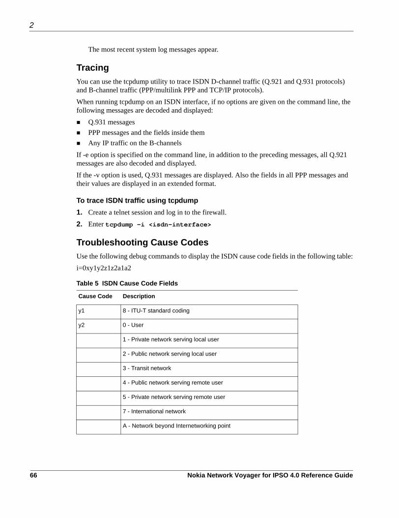
2
The most recent system log messages appear.
TracingYou can use the tcpdump utility to trace ISDN D-channel traffic (Q.921 and Q.931 protocols) and B-channel traffic (PPP/multilink PPP and TCP/IP protocols).When running tcpdump on an ISDN interface, if no options are given on the command line, the following messages are decoded and displayed:
Q.931 messagesPPP messages and the fields inside themAny IP traffic on the B-channels
If -e option is specified on the command line, in addition to the preceding messages, all Q.921 messages are also decoded and displayed.If the -v option is used, Q.931 messages are displayed. Also the fields in all PPP messages and their values are displayed in an extended format.
To trace ISDN traffic using tcpdump1. Create a telnet session and log in to the firewall.2. Enter tcpdump -i <isdn-interface>
Troubleshooting Cause CodesUse the following debug commands to display the ISDN cause code fields in the following table:i=0xy1y2z1z2a1a2
Table 5 ISDN Cause Code Fields
Cause Code Description
y1 8 - ITU-T standard coding
y2 0 - User
1 - Private network serving local user
2 - Public network serving local user
3 - Transit network
4 - Public network serving remote user
5 - Private network serving remote user
7 - International network
A - Network beyond Internetworking point
66 Nokia Network Voyager for IPSO 4.0 Reference Guide

ISDN Cause Values Descriptions of the cause-value field of the cause-information element are shown in the following ISDN cause value table. Cause-value numbers are not consecutive.
z1 Class of cause value
z2 Value of cause value
a1 (Optional) Diagnostic field that is always 8.
a2 (Optional) Diagnostic field that is one of the following values: 0 is Unknown, 1 is Permanent, and 2 is Transient
Table 6 Cause Values
Cause Cause Description Diagnostics
1 Unallocated (unassigned) number Note 12
2 No route to specified transit network Transit-network identity (Note 11)
3 No route to destination Note 12
6 Channel unacceptable
7 Call awarded and being delivered in an established channel
16 Normal call clearing Note 12
17 User busy
18 No user responding
19 No answer from user (user alerted)
21 Call rejected User-supplied diagnostic (Notes 4 & 12)
22 Number changed
26 Non-selected user clearing
27 Designation out of order
28 Invalid number format
29 Facility rejected Facility identification (Note 1)
Table 5 ISDN Cause Code Fields
Cause Code Description
Nokia Network Voyager for IPSO 4.0 Reference Guide 67

2
30 Response to STATUS ENQUIRY
31 Normal, unspecified
34 No circuit or channel available Note 10
38 Network out of order
41 Temporary failure
42 Switching-equipment congestion
43 Access information discarded Discarded information-element identifier(s) (Note 6)
44 Requested circuit / channel not available Note 10
47 Resources unavailable or unspecified
49 Quality of service unavailable. See ISDN Cause Values table.
50 Requested facility not subscribed Facility identification (Note 1)
57 Bearer capability not authorized Note 3
58 Bearer capability not presently available Note 3
63 Service or option not available or specified Note 3
65 Bearer capability not implemented Note 3
66 Channel type not implemented Channel Type (Note 7)
69 Requested facility not implemented Facility Identification (Note 1)
70 Only restricted digital-information bearer is available
79 Service or option not available or specified
81 Invalid call-reference value
82 Identified channel does not exist Channel identity
83 A suspended call exists, but call identity does not exist
84 Call identity in use
85 No call suspended
Table 6 Cause Values
Cause Cause Description Diagnostics
68 Nokia Network Voyager for IPSO 4.0 Reference Guide

Notes for Table 6:Note 1—The coding of facility identification is network dependent. Note 2—Incompatible parameter is composed of incompatible information element identifier. Note 3—The format of the diagnostic field for cause 57, 58, and 65 is shown in the ITU-T Q.931 specification. Note 4—User-supplied diagnostic field is encoded according to the user specification, subject to the maximum length of the cause-information element. The coding of user-supplied diagnostics should be made in such a way that it does not conflict with the coding described in Table B-2. Note 5—New destination is formatted as the called-party number information element, including information element identifier. Transit network selection might also be included.
86 Call having the requested-call identity has been cleared
Clearing cause
88 Incompatible destination Incompatible parameter (Note 2)
91 Invalid transit-network selection
95 Invalid message, unspecified
96 Mandatory information element is missing Information element identifiers
Information-element identifiers is missing
97 Message type non-existent or not implemented Message type
98 Message not compatible with call state or message type or not implemented
Message type non-existent
99 Information-element non-existent or not implemented
Information-element identifiers not implemented (Notes 6 & 8)
100 Invalid-information element Information-element identifiers contents (Note 6)
101 Message not compatible with call Message type state
102 Recovery on timer expires Timer number (Note 9)
111 Protocol error, unspecified
127 Internetworking, unspecified
Table 6 Cause Values
Cause Cause Description Diagnostics
Nokia Network Voyager for IPSO 4.0 Reference Guide 69

2
Note 6—Locking and non-locking shift procedures described in the ITU-T Q.931 specification apply. In principle, information element identifiers are in the same order as the information elements in the received message. Note 7—The following coding applies: Bit 8, extension bitBits 7 through 5, spareBits 4 through 1, according to Table 4-15/Q.931 octet 3.2, channel type in ITU-T Q.931 specification. Note 8—When only the locking shift-information element is included and no variable length information-element identifier follows, it means that the codeset in the locking shift itself is not implemented. Note 9—The timer number is coded in IA5 characters. The following coding is used in each octet: Bit 8, Spare “0” Bits 7 through 1, IA5 character Note 10—Examples of the cause values to be used for various busy or congested conditions appear in Annex J of the ITU-T Q.931 specification. Note 11—The diagnostic field contains the entire transit network selection or network-specific facilities information element, as applicable.Note 12—For the coding that is used, see ISDN Cause Codes table.
ISDN Bearer-Capable ValuesThe ISDN bearer-capability values that display in the SETUP packet using the tracing tcpdump command follows:0x8890 for 64 Kbps or 0x218F for 56 Kbps
Value Description
88 ITU-T coding standard; unrestricted digital information
90 Circuit mode, 64 Kbps
21 Layer 1, V.110 / X.30
8F Synchronous, no in-band negotiation, 56 Kpbs
70 Nokia Network Voyager for IPSO 4.0 Reference Guide

Token Ring InterfacesTo configure a Token Ring interface1. Click Interfaces under Configuration > Interface Configuration in the tree view.2. Click the physical interface link to configure in the Physical column.
Example: tok-s3p1The physical interface setup page appears.
3. In the Ring Speed column of the Physical configuration table, select the desired value: 16 Mbit/sec or 4 Mbit/sec. There is no default value.
4. In the MTU field, enter the desired value. The minimum for both ring speeds is 560. The maximum MTU for 4 Mbs is 4442, and the maximum MTU for 16 Mbs is 17792.
5. In the Allow Source routes (Multi-Ring) field, select On or Off. Default is On. This feature specifies whether or not to support source routes.
6. In the Select Use Broadcast instead of Multicast field, select On or Off. Default is Off. This option specifies the mapping of an IP multicast address. When the option is on, it maps a multicast address to an all-ring broadcast address: [ff:ff:ff:ff:ff:ff]. When the option is off, it maps a multicast IP address to an IEEE-assigned IP multicast group address: [noncanonical form: c0:00:00:04:00:00].
7. Click the logical interface name in the Interface column of the Logical interfaces table to go to the Interface page.
8. In the Active column of the Logical interfaces table, select On or Off. Default is On. This setting enables or disables the logical interface. Use this switch to control access to the network or virtual circuit that corresponds to the logical interface.
9. Click Apply. Click Up to return to the interface configuration page.
10. Click the logical interface link to configure in the Logical column.Example: tok-s3p1c0The logical interface setup page appears.
11. Enter the IP address for the device in the New IP address text box.12. Enter the IP subnet mask length in the New Mask Length text box.
Click Apply. Each time you click Apply, the configured IP address and mask length are added to the table. The entry fields remain blank to allow you to add more IP addresses.
Nokia Network Voyager for IPSO 4.0 Reference Guide 71

2
13. (Optional) Change the interfaces logical name to a more meaningful name by typing the preferred name in the Logical name text box. Click Apply.
14. (Optional) Add a comment to further define the logical interfaces function in the Comments text box. Click Apply.
15. Click Save to make your changes permanent.
To deactivate a Token Ring interface1. Click Interfaces under Configuration > Interface Configuration in the tree view.2. In the Active column of the interface to deactivate, click off.3. Click Apply.4. Click Save to make your changes permanent.
To change a Token Ring interface1. Click Interfaces under Configuration > Interface Configuration in the tree view.2. In the Physical column, click the physical interface link to change. Example: tok-s3p1.
To change only the properties of a logical interface, proceed to Step 6.The Physical Interface Setup page appears.
3. Perform the following procedures to make the desired changes. If no change is desired, skip this step.a. In the Ring Speed column of the Physical configuration table, select the desired value: 16
Mbit/sec or 4 Mbit/sec. There is no default value.b. In the MTU field, enter the desired value. The minimum for both ring speeds is 560. The
maximum MTU for 4 Mbs is 4442, and the maximum MTU for 16 Mbs is 17792.c. In the Allow Source routes (Multi-Ring) field, select On or Off. Default is On.d. In the Select Use Broadcast instead of Multicast, select On or Off. Default is Off.e. In the Active column of the Logical interfaces table, select On or Off. Default is On.
4. Click Apply. 5. Click Up to return to the interface configuration page.6. (Optional) To change a logical interface link, click the logical interface link to change in the
Logical column.Example: tok-s3p1c0The Logical Interface setup page appears.
7. Perform the following procedures to make the desired changes.
72 Nokia Network Voyager for IPSO 4.0 Reference Guide

If no change is desired, skip the step.a. To change the IP address, enter the appropriate IP address in the New IP address field,.
There is no default.b. In the New mask length field, enter the appropriate value. The range is 8 to 30, and there
is no default.c. To delete an IP address, click the Delete box.
NoteChanging an IP address and deleting an IP address at the same time prevents multiple addresses from being assigned to a single interface.
8. Click Apply.9. Click Save.
Token Ring ExampleThis section describes how you might use Network Voyager to configure the interfaces of your IP security platform in an example network.In a company’s main office, IP650 A terminates a serial line to an Internet service provider, running PPP with a keepalive value of 10.IP650 A also provides Internet access for an FDDI ring and a remote branch office connected a with Token Ring.The branch office contains IP650 B, which routes traffic between a local fast Ethernet network and a Token Ring. IP650 B provides access to the main office and the Internet. This example configures the Token Ring interface on IP650 A.
Nokia Network Voyager for IPSO 4.0 Reference Guide 73

2
The following figure shows the network configuration for this example.
1. Click Interfaces under Configuration > Interface Configuration in the tree view.2. Select tok-s2p1 in the Physical column of the table.3. Set the desired value in the Ring Speed column of the Physical configuration table.
NoteThis setting must be the same for all hosts on the network to which the device connects.
4. Enter the desired MTU value.5. In the Allow Source routes (Multi-Ring) field, select On or Off.6. In the Select Use Broadcast instead of Multicast, select On or Off.7. Under the Active column of the Logical interfaces table, select On or Off.8. Click Apply.
Click Up to return to the interface configuration page.9. Click the logical interface link to configure in the Logical column.
Nokia Platform A
Nokia Platform B
tok-s2p1c0 (192.168.3.2)
tok-s1p1c0 (192.168.3.1)
ser-s1p1c0 (192.168.2.1)
eth-s2p1c0 (192.168.4.1/24)
192.168.4.xxx
FDDI192.168.1.xxx (192.168.1.1/24)
192.168.3.4 192.168.3.5
fddi-s3p1c0
(192.168.2.93)Provider
00038
Server
Server
Server(Optional)
Server(Optional)
Server
Token RingMAU
74 Nokia Network Voyager for IPSO 4.0 Reference Guide

10. In the New IP Address field, enter the appropriate IP address.11. In the New Mask Length field, enter the appropriate value.12. Click Apply.13. Click Save.
Point-to-Point Link over ATMTo configure an ATM interface
NoteYou cannot configure an ATM interface with an IP address until at least one logical interface is created for the interface.
1. Click Interfaces under Configuration > Interface Configuration in the tree view.2. Click the physical interface link to configure in the Physical column on the Interface
Configuration page.Example: atm-s2p1The Physical Interface page is displayed.
3. Select SONET or SDH as the framing format in the Physical Configuration table.
NoteSONET and SDH settings are available only if the ATM interface card supports them.
The setting should match the type of transmission network to which the interface is connected.
4. Select Freerun or Loop Timing as the transmit clock choice in the Physical Configuration table.
NoteThe Transmit Clock settings are available only if the ATM interface card supports them.
Freerun uses the internal clock. If two ATM interfaces are directly connected, at least one of them must use the internal clock.Loop timing derives the transmit clock from the recovered receive clock
5. Select the VPI/VCI range in the VPI/VCI Range Configuration list box.6. Select point-to-point in the Type list box in the Create a new LLC/SNokia Platform
RFC1483 interface section. Enter the VPI/VCI number in the VPI/VCI text box.
Nokia Network Voyager for IPSO 4.0 Reference Guide 75

2
7. Click Apply.A new logical interface appears in the Interface column. The new interface is on by default.You can add more ATM logical interfaces by repeating this action.
8. Click the logical interface name in the Interface column of the Logical Interfaces table to go to the Logical Interface page.
9. Enter the IP address for the local end of the PVC in the Local Address text box.10. Enter the IP address of the remote end of the PVC in the Remote Address text box.
Click Apply.11. Enter a number in the IP MTU text box to configure the device’s maximum length (in bytes)
of IP packets transmitted in this interface. Click Apply. The default value is 1500.
NoteThe maximum packet size must match the MTU of the link partner.
12. (Optional) Change the interfaces logical name to a more meaningful name by typing the preferred name in the Logical Name text box.
13. Click Apply.14. (Optional) Add a comment to further define the logical interfaces function in the Comments
text box. 15. Click Apply.16. Click Save to make your changes permanent.
To change the VPI/VCI of an ATM interface
NoteTo move an IP address from one PVC to another, you must first delete the logical interface for the old PVC, then create a new logical interface for the new PVC.
1. Click Interfaces under Configuration > Interface Configuration in the tree view.2. Click the physical interface link to configure in the Physical column.
Example: atm-s2p13. Find the ATM logical interface you wish to remove in the Logical Interfaces table and click
the corresponding Delete button. 4. Click Apply.
The logical interface disappears from the list. Any IP addresses configured on this interface are also removed.
5. Select the VPI/VCI range in the VPI/VCI Range Configuration selection box.
76 Nokia Network Voyager for IPSO 4.0 Reference Guide

6. Select point-to-point in the Type selection box in the Create a new LLC/SNokia Platform RFC1483 interface section. Enter the VPI/VCI number in the VPI/VCI text box.
7. Click Apply.A new logical interface appears in the Interface column. The new interface is turned on by default.
8. Click the logical interface name in the Interface column of the Logical Interfaces table to go the Interface page.
9. Enter the IP address for the local end of the PVC in the Local Address text box.10. Enter the IP address of the remote end of the PVC in the Remote Address text box. 11. Click Apply.12. (Optional) Enter the desired value in the IP MTU text box. 13. Click Apply.14. (Optional) Change the interface’s logical name to a more meaningful one by typing the
preferred name in the Logical Name text box. 15. Click Apply.16. Click Save to make your changes permanent.
To change the IP Address of an ATM interface
NoteDo not change the IP address you use in your browser to access Network Voyager. If you do, you can no longer access the IP security platform (unit) with your browser.
1. Click Interfaces under Configuration > Interface Configuration in the tree view.2. Click the logical interface link for which to change the IP address in the Logical column.
Example: atm-s2p1c83. Delete the current addresses from the Local Address and Remote Address text boxes, and
replace with new address entries. Click Apply. The original MTU value is retained.
4. Click Save to make your changes permanent
To change the IP MTU of an ATM interface1. Click Interfaces under Configuration > Interface Configuration in the tree view.2. In the Logical column, click the Logical interfaces link for the item on which to change the
IP address.Example: atm-s2p1
3. Enter a number in the IP MTU text box to configure the device’s maximum length (in bytes) of IP packets transmitted on this interface.
Nokia Network Voyager for IPSO 4.0 Reference Guide 77

2
NoteThe maximum packet size must match the MTU of the link partner. Packets longer than the length you specify are fragmented before transmission.
4. Click Apply.5. Click Save to make your changes permanent.
ATM Example This section describes how you might configure the interfaces of your IP security platform in an example network, using Network Voyager.The following figure shows the network configuration for this example.
In a company’s main office, Nokia Platform A terminates a serial line to an Internet service provider, running PPP with a keepalive value of 10.Nokia Platform A also provides Internet access for an FDDI ring and a remote branch office connected through ATM PVC 93.The branch office contains Nokia Platform B, which routes traffic between a local fast Ethernet network and ATM PVC 52. It provides access to the main office and the Internet.
Nokia Platform A
Nokia Platform B
atm-s1p1c52 (192.168.3.1)
atm-s2p1c93 (192.168.3.2)
ser-s1p1c0 (192.168.2.1)
eth-s2p1c0 (192.168.4.1/24)
192.168.4.xxx
FDDI192.168.1.xxx (192.168.1.1/24)
fddi-s3p1c0
(192.168.2.93)Provider
00037
Server
Server Server
ATMSwitch
78 Nokia Network Voyager for IPSO 4.0 Reference Guide

To configure the ATM interface on Nokia Platform A1. Click Interfaces under Configuration > Interface Configuration in the tree view.2. Select atm-s2p1 in the Physical column of the table.3. Enter 93 in the VCI text box in the Create a new LLC/SNokia Platform RFC1483 interface
section.The channel number of the interface is no longer the VCI number but an automatically allocated number. Therefore, the logical name of the interface in step 6 is something that depends on what other logical ATM interfaces there are. Find the newly created interface from the table before you continue.
4. Click Apply.5. Click atm-s2p1c93 in the Logical Interfaces table. The Interface page is displayed.6. Enter 192.168.3.2 in the Local Address text box.7. Enter 192.168.3.1 in the Remote Address text box.8. Click Apply9. Enter 9180 in the IP MTU text box.10. Click Apply.11. Click Save.
NoteThe steps for configuring the ATM interface on Nokia Platform B are the same except that you should set the to 52 when you create the logical interface and reverse the IP addresses should be reversed.
IP over ATM (IPoA)To configure an ATM logical IP subnet (LIS) interface1. Click Interfaces under Configuration > Interface Configuration in the tree view.2. Click the physical interface link to configure in the Physical column. Example: atm-s2p1.
The Physical Interface page is displayed.3. Select SONET or SDH as the framing format in the Physical Configuration table.
The setting should match the type of transmission network to which the interface is connected.
4. Select Freerun or Loop Timing as the transmit clock choice in the Physical Configuration table.Freerun uses the internal clock. If two ATM interfaces are directly connected, at least one of them must use the internal clock.
Nokia Network Voyager for IPSO 4.0 Reference Guide 79

2
Loop timing derives the transmit clock from the recovered receive clock.5. Select the VPI/VCI range in the VPI/VCI Range Configuration list box.6. Create a logical interface with the Create a new LLC/SNokia Platform RFC1483 interface
section by selecting LIS in the Type list box and entering the set of VPI/VCI numbers that the interface in the VPI/VCI text box will use.The set of VPI/VCIs can be given as a comma-separated list of VPI/VCIs or VPI/VCI ranges such as 1/42, 1/48, 1/50 to 60.
7. Click Apply.A new logical interface appears in the Interface column. The new interface is on by default.You can create multiple logical interfaces by repeating steps 6 through 7.
8. Click the logical interface name in the Interface column of the Logical Interfaces table to reach the Logical Interface page.
9. Enter the IP address of the interface in the IP Address text box.10. Enter the IP subnet mask length in the Mask Length text box.11. Enter a number in the IP MTU text box to configure the device’s maximum length (in bytes)
of IP packets transmitted in this interface.
The default value and range depend on the hardware configuration. The standard value is 9180. Click Apply.
NoteAll hosts in the same LIS must use the same IP MTU in their interface to the LIS.
12. (Optional) Change the interfaces logical name to a more meaningful one by typing the preferred name in the Logical name text box. Click Apply.
13. (Optional) Add a comment to further define the logical interfaces function in the Comments text box.
14. Click Apply.15. Click Save to make your changes permanent.
To change the VPI/VCIs of an ATM LIS Interface
NoteDo not change the VCI address of the connection you are using. If you do, you can no longer access the IP security platform with your browser.
1. Click Interfaces under Configuration > Interface Configuration in the tree view.2. Click the physical interface link to configure in the Physical column. Example: atm-s2p1.
80 Nokia Network Voyager for IPSO 4.0 Reference Guide

The Physical Interface page appears.3. Select the VPI/VCI range in the VPI/VCI Range Configuration list box.4. Find the ATM logical interface to reconfigure in the Logical Interfaces table and enter a new
set of VPI/VCIs in the VPI/VCI field. 5. Click Apply.6. Click Save to make your changes permanent.
To change the IP Address of an ATM LIS interface
NoteDo not change the IP address you use in your browser to access Network Voyager. If you do, you can no longer access the IP security platform with your browser.
1. Click Interfaces under Configuration > Interface Configuration in the tree view.2. Click the logical interface link for which to change the IP address in the Logical column.
Example: atm-s2p1c8The Logical Interface page appears.
3. Enter the IP address for the interface in the IP Address text box.4. Enter the IP subnet mask length in the Mask Length text box.5. Click Apply.6. Click Save to make your changes permanent.
To change the IP MTU of an ATM interface1. Click Interfaces under Configuration > Interface Configuration in the tree view.2. In the Logical column, click the Logical interface link for the item on which to change the IP
MTU. Example: atm-s2p1c8.3. Enter a number in the IP MTU text box to configure the devices maximum length (in bytes)
of IP packets transmitted on this interface.
NoteAll hosts in the same LIS must use the same IP MTU in their interface to the LIS.
Packets longer than the length you specify are fragmented before transmission.4. Click Apply. 5. Click Save to make your changes permanent.
Nokia Network Voyager for IPSO 4.0 Reference Guide 81

2
IPoA ExampleThis section describes how you might configure the interfaces of your IP security platform in an example network, using Network Voyager.The following figure shows the network configuration for this example.
A company has five Ethernet networks in three separate locations. The networks are connected to each other with three routers that belong to the same logical IP subnet over ATM. This example configures the ATM interface on Nokia Platform A. The interface is connected to Nokia Platform B through ATM PVC 42 and to Nokia Platform C through ATM PNC 53. Nokia Platform B and Nokia Platform C are connected to each other through an ATM PVC; their ATM interfaces have already configured.
To configure the ATM interface on Nokia Platform A1. Click Interfaces under Configuration > Interface Configuration in the tree view.2. Click the physical interface link to configure in the Physical column. Example: atm-s2p1.
The Physical Interface page appears.3. Create a logical interface in the Create a new LLC/SNokia Platform RFC1483 interface
section by selecting LIS in the Type list box.4. Enter 42,53 in the VCI(s) text box.5. Click Apply.6. Click the newly created interface (atm-s2p1c0) in the Logical Interfaces table to reach the
Logical Interface page.7. Enter 10.0.0.1 in the IP Address text box.8. Enter 24 in the Mask Length text box.
ATMSwitch
00125
eth-s1p1c0
eth-s1p1c0 eth-s2p2c0 eth-s1p1c0 eth-s2p2c0
atm-s2p1c0 (10.0.0.1/24)
PVC 42 to Nokia Platform BPVC 53 to Nokia Platform C
atm-s3p1c0 (10.0.0.3/24)atm-s3p1c0 (10.0.0.2/24)
Nokia Platform A
Nokia Platform CNokia Platform B
82 Nokia Network Voyager for IPSO 4.0 Reference Guide

9. Click Apply.10. (Optional) Change the interfaces logical name to a more meaningful name by typing the
preferred name in the Logical name text box. Click Apply.
11. (Optional) Add a comment to further define the logical interfaces function in the Comments text box.
12. Click Apply.13. Click Save.
Serial (V.35 and X.21) InterfacesTo configure a serial interface for Cisco HDLC 1. Click Interfaces under Configuration > Interface Configuration in the tree view.2. Click the physical interface link to configure in the Physical column.
Example: ser-s2p1
3. (Optional) Click On or Off in the Physical configuration table Internal Clock field to set the internal clock on the serial device. Set the internal clock to On when you are connecting to a device or system that does not provide a clock source. Otherwise, set the internal clock to Off.
4. Click Apply.5. If you turned the internal clock on, enter a value in the Internal clock speed text box.
If the device can generate only certain line rates, and the configured line rate is not one of these values, the device selects the next highest available line rate.
6. Click Full Duplex or Loopback in the Channel Mode field.Full duplex is the normal mode of operation.
7. Click Cisco HDLC in the Encapsulation field. 8. Click Apply.
A logical interface appears in the Logical Interfaces table.9. Enter a number in the Keepalive text box to configure the Cisco HDLC keepalive interval.
Click Apply.This value sets the interval, in seconds, between keepalive protocol message transmissions. These messages are used periodically to test for an active remote system.
NoteThis value must be identical to the keepalive value configured on the system at the other end of a point-to-point link, or the link state fluctuates.
Nokia Network Voyager for IPSO 4.0 Reference Guide 83

2
10. Click the logical interface name in the Interface column of the Logical interfaces table.The Interface page appears.
11. Enter the IP address for the local end of the link in the Local address text box.12. Enter the IP address of the remote end of the link in the Remote address text box.
Click Apply.13. (Optional) Change the interfaces logical name to a more meaningful name by typing the
preferred name in the Logical name text box. Click Apply.
14. (Optional) Add a comment to further define the logical interfaces function in the Comments text box. Click Apply.
15. Click Save to make your changes permanent.
To configure a Serial Interface for PPP1. Click Interfaces under Configuration > Interface Configuration in the tree view.2. Click the physical interface link to configure in the Physical column. Example: ser-s2p1.3. (Optional) Click On or Off in the Physical configuration table Internal Clock field to set the
internal clock on the serial device.Click Apply.Set the internal clock to On when you are connecting to a device or system that does not provide a clock source. Otherwise, set the internal clock to Off.
4. If you turned the internal clock on, enter a value in the Internal clock speed text box.If the device can generate only certain line rates, and the configured line rate is not one of these values, the device selects the next highest available line rate.
5. Click Full Duplex or Loopback in the Channel Mode field.Full duplex is the normal mode of operation.
6. Click the PPP radio button in the Encapsulation field. 7. Click Apply.
A logical interface appears in the Logical Interfaces table.8. Enter a number in the Keepalive text box to configure the PPP keepalive interval.
This value sets the interval, in seconds, between keepalive protocol message transmissions. These messages are used periodically to test for an active remote system.
NoteThis value must be identical to the keepalive value configured on the system at the other end of a point-to-point link, or the link state fluctuates.
84 Nokia Network Voyager for IPSO 4.0 Reference Guide

9. Click Apply.10. Enter a number in the Keepalive maximum failures text box.
This value sets the number of times a remote system can fail to send a keepalive protocol message within a keepalive interval before the systems considers the link down.
11. Click Apply.12. Click the Advanced PPP Options link.
The PPP Advanced Options page appears.13. Click Yes or No in the Negotiate Magic Number field.
Clicking Yes enables the interface to send a request to negotiate a magic number with a peer.14. Click Yes or No in the Negotiate Maximum Receive Unit field.
Clicking Yes enables the interface to send a request to negotiate an MRU with a peer.15. Click Apply.16. Click Up to return to the Physical Interface page.17. Click the logical interface name in the Interface column of the Logical Interfaces table to go
to the Interface page.
18. Enter the IP address for the local end of the link in the Local address text box.19. Enter the IP address of the remote end of the link in the Remote address text box. Click
Apply.20. (Optional) Change the interfaces logical name to a more meaningful name by typing the
preferred name in the Logical name text box. Click Apply.
21. (Optional) Add a comment to further define the logical interfaces function in the Comments text box. Click Apply.
22. To make your changes permanent, click Save.
To configure a serial interface for frame relay1. Click Interfaces under Configuration > Interface Configuration in the tree view.2. Click the physical interface link to configure in the Physical column. Example: ser-s2p1.3. (Optional) Click On or Off in the Physical configuration table Internal Clock field to set the
internal clock on the serial device. Set the internal clock to On when you are connecting to a device or system that does not provide a clock source. Otherwise, set the internal clock to Off.
4. Click Apply.5. If you turned the internal clock on, enter a value in the Internal clock speed text box.
If the device can generate only certain line rates, and the configured line rate is not one of these values, the device selects the next highest available line rate.
Nokia Network Voyager for IPSO 4.0 Reference Guide 85

2
6. Click Full Duplex or Loopback radio in the Channel Mode field.Full duplex is the normal mode of operation.
7. Click the Frame relay radio button in the Encapsulation field. 8. Click Apply.9. Enter a number in the Keepalive text box to configure the frame relay keepalive interval.
This value sets the interval, in seconds, between keepalive protocol message transmissions. These messages are used periodically to test for an active remote system.
NoteThis value must be identical to the keepalive value configured on the system at the other end of a point-to-point link, or the link state fluctuates.
10. Click Apply.11. Click DTE or DCE in the Interface Type field.
DTE is the usual operating mode when the device is connected to a Frame Relay switch.12. Click On or Off in the Active Status Monitor field.
This actions sets the monitoring of the connection-active status in the LMI status message.13. (Optional) Click the Advanced Frame Relay Options link to go to the Frame Relay
Advanced Options page.The Frame Relay Advanced Options page allows you to configure frame relay protocol and LMI parameters for this device.
NoteThe values you enter depend on the settings of the frame relay switch to which you are connected or to the subscription provided by your service provider.
14. From the Frame Relay Advanced Options page, click Up to return to the Physical Interface page.
15. Enter the DLCI number in the Create a new interface DLCI text box.
16. Click Apply.A new logical interface appears in the Interface column. The DLCI number appears as the channel number in the logical interface name. The new interface is on by default.
17. (Optional) Enter another DLCI number in the DLCI text box to configure another frame relay PVC.
18. Click Apply.Each time you click Apply after you enter a DLCI, a new logical interface appears in the Interface column. The DLCI entry field remains blank to allow you to add more frame relay logical interfaces.
86 Nokia Network Voyager for IPSO 4.0 Reference Guide

19. Click the logical interface name in the Interface column of the Logical interfaces table to go the Interface page.
20. Enter the IP address for the local end of the PVC in the Local address text box.21. Enter the IP address of the remote end of the PVC in the Remote address text box.
Click Apply.22. (Optional) Change the interfaces logical name to a more meaningful name by typing the
preferred name in the Logical name text box. 23. Click Apply.24. Click Save to make your changes permanent.
Serial Interface ExampleThis section describes how you might configure the interfaces of your IP security platform in an example network, using Network Voyager.The following figure shows the network configuration for this example.
In a company’s main office, Nokia Platform A terminates a serial line to an Internet service provider, running PPP with a keepalive value of 10.Nokia Platform A also provides Internet access for a FDDI ring and a remote branch office connected through ATM PVC 93.
Nokia Platform A
Nokia Platform B
atm-s1p1c52 (192.168.3.1)
atm-s2p1c93 (192.168.3.2)
ser-s1p1c0 (192.168.2.1)
eth-s2p1c0 (192.168.4.1/24)
192.168.4.xxx
FDDI192.168.1.xxx (192.168.1.1/24)
fddi-s3p1c0
(192.168.2.93)Provider
00037
Server
Server Server
ATMSwitch
Nokia Network Voyager for IPSO 4.0 Reference Guide 87

2
The branch office contains Nokia Platform B, which routes traffic between a local Fast Ethernet network and ATM PVC 52. It provides access to the main office and the Internet.
To configure the serial interface on Nokia Platform A1. Click Interfaces under Configuration > Interface Configuration in the tree view.2. Select ser-s1p1 in the Physical column of the table.3. Click PPP in the Encapsulation field.4. Click Apply.5. Enter 10 in the Keepalive text box. 6. Click Apply.7. Click ser-s1p1c0 in the logical interfaces table to go to the Interface page.8. Enter 192.168.2.1 in the Local address text box.9. Enter 192.168.2.93 in the Remote address text box.10. Click Apply.11. (Optional) Change the interfaces logical name to a more meaningful name by typing the
preferred name in the Logical name text box. 12. Click Apply.13. (Optional) Add a comment to further define the logical interfaces function in the Comments
text box. 14. Click Apply.15. Click the Up button to go to the Interfaces page.16. Click the On radio button for ser-s1p1c0.17. Click Apply.18. Click Save.
T1(with Built-In CSU/DSU) InterfacesTo configure a T1 Interface for Cisco HDLC1. Click Interfaces under Configuration > Interface Configuration in the tree view.2. Click the interface link to configure in the Physical column. Example: ser-s2p1.3. (Optional) Click On or Off in the Internal Clock field to set the internal clock on the T1
device. If you are connecting to a device or system that does not provide a clock source, set Internal Clock to On; otherwise, set it to Off. Internal clocking for T1 is fixed at 1.544 Mbps. To configure slower speeds, you must configure fractional T1 on the Advanced T1 CSU/DSU Options page.
88 Nokia Network Voyager for IPSO 4.0 Reference Guide

4. Click Apply.5. Click the Full Duplex or Loopback radio button in the Channel Mode field.
Full duplex is the normal mode of operation.6. Click AMI or B8ZS in the T1 Encoding field to select the T1 encoding.
This setting must match the line encoding of the CSU/DSU at the other end of the point-to-point link.
7. Click Apply.8. Click Superframe (D4) or Extended SF in the T1 Framing field to select the T1 Framing
format. Use T1 framing to divide the data stream into 64 Kbps channels and to synchronize with the remote CSU/DSU. This setting must match the frame format that the CSU/DSU uses at the other end of the point-to-point link.
9. Click Apply.10. Click 64bps or 56bps in the T1 Channel Speed field to select the DS0 channel speed for the
T1 line.Some older trunk lines use the least-significant bit of each DS0 channel in a T1 frame for switching-equipment signaling. T1 frames designed for data transfer can be set to not use the least-significant bit of each DS0 channel. This setting allows data to be sent over these trunk lines without corruption but at a reduced throughput. This mode is called the 56 Kbps mode because each DS0 channel now has an effective throughput of 56 Kbps instead of 64 Kbps. All T1 functions still work in the 56 Kbps mode, including all framing modes and fractional T1 configurations.
11. If you selected Extended SF as the T1 Framing format, click ANSI or None in the FDL Type field to select the FDL type.
12. Click Cisco HDLC in the Encapsulation field. 13. Click Apply.
A logical interface appears in the Logical interfaces table.14. Enter a number in the Keepalive text box to configure the Cisco HDLC keepalive interval.
Click Apply.This value sets the interval, in seconds, between keepalive protocol message transmissions. These messages are used periodically to test for an active remote system.
NoteThis value must be identical to the keepalive value configured on the system at the other end of a point-to-point link, or the link state fluctuates.
15. (Optional) Click the Advanced T1 CSU/DSU Options link to select advanced T1 options.
Nokia Network Voyager for IPSO 4.0 Reference Guide 89

2
The T1 CSU/DSU Advanced Options page allows you to configure fractional T1 channels, line build-out values and other advanced settings for the T1 device. The values you enter on this page are dependent on the subscription provided by your service provider.
16. From the Advanced T1 CSU/DSU Options page, click Up to return to the physical interface page.
17. Click the logical interface name in the Interface column of the Logical interfaces table to go to the Interface page.
18. Enter the IP address for the local end of the link in the Local address text box.19. Enter the IP address of the remote end of the link in the Remote address text box.
Click Apply.20. (Optional) Change the interfaces logical name to a more meaningful name by typing the
preferred name in the Logical name text box. Click Apply.
21. (Optional) Add a comment to further define the logical interfaces function in the Comments text box.
22. Click Apply.23. Click Save to make your changes permanent.
To configure a T1 Interface for PPP1. Click Interfaces under Configuration > Interface Configuration in the tree view.2. Click the interface link to configure in the Physical column. Example: ser-s2p1.3. (Optional) Click On or Off in the Internal Clock field to set the internal clock on the T1
device. When you connect to a device or system that does not provide a clock source, set Internal Clock to On; otherwise, set it to Off. Internal clocking for T1 is fixed at 1.544 Mbps. To configure slower speeds, you must configure fractional T1 on the Advanced T1 CSU/DSU Options page.
4. Click Apply.5. Click Full Duplex or Loopback in the Channel Mode field.
Full duplex is the normal mode of operation.6. Click AMI or B8ZS in the T1 Encoding field to select the T1 encoding.
This setting must match the line encoding of the CSU/DSU at the other end of the point-to-point link.
7. Click Apply.8. Click Superframe (D4) or Extended SF in the T1 Framing field to select the T1 Framing
format.
90 Nokia Network Voyager for IPSO 4.0 Reference Guide

Use T1 framing to divide the data stream into 64 Kbps channels and to synchronize with the remote CSU/DSU. This setting must match the frame format used by the CSU/DSU at the other end of the point-to-point link.
9. Click Apply.10. Click 64bps or 56bps in the T1 Channel Speed field to select the DS0 channel speed for the
T1 line.Some older trunk lines use the least-significant bit of each DS0 channel in a T1 frame for switching-equipment signaling. T1 frames designed for data transfer can be set to not use the least-significant bit of each DS0 channel. This setting allows data to be sent over these trunk lines without corruption but at a reduced throughput. This mode is called the 56 Kbps mode because each DS0 channel now has an effective throughput of 56 Kbps instead of 64 Kbps. All T1 functions still work in the 56 Kbps mode, including all framing modes and fractional T1 configurations.
11. If you selected Extended SF as the T1 Framing format, click ANSI or None in the FDL Type field to select the FDL type.
12. Click the PPP in the Encapsulation field. 13. Click Apply.
A logical interface appears in the Logical Interfaces table.14. Enter a number in the Keepalive text box to configure the PPP keepalive interval.
This value sets the interval, in seconds, between keepalive protocol message transmissions. These messages are used periodically to test for an active remote system.
NoteThis value must be identical to the keepalive value configured on the system at the other end of a point-to-point link, or the link state fluctuates.
15. Click Apply.16. Enter a number in the Keepalive maximum failures text box.
This value sets the number of times a remote system may fail to send a keepalive protocol message within a keepalive interval before the systems considers the link down.
17. Click Apply.18. (Optional) Click the Advanced T1 CSU/DSU Options link to select advanced T1 options.
The T1 CSU/DSU Advanced Options page allows you to configure fractional T1 channels, line build-out values, and other advanced settings for a T1 device. The values you enter on this page depend on the subscription provided by your service provider.
19. From the Advanced T1 CSU/DSU Options page, click Up to return to the physical interface page.
20. Click the Advanced PPP Options link.The PPP Advanced Options page appears.
Nokia Network Voyager for IPSO 4.0 Reference Guide 91

2
21. Click Yes or No in the Negotiate Magic Number field.Clicking Yes enables the interface to send a request to negotiate a magic number with a peer.
22. Click Yes or No in the Negotiate Maximum Receive Unit field.Clicking Yes enables the interface to send a request to negotiate an MRU with a peer.
23. Click Apply.24. Click Up to return to the Physical Interface page.25. Click the logical interface name in the Interface column of the Logical Interfaces table to go
to the Interface page.26. Enter the IP address for the local end of the link in the Local address text box.27. Enter the IP address of the remote end of the link in the Remote address box.
Click Apply.28. (Optional) Change the interfaces logical name to a more meaningful name by typing the
preferred name in the Logical name text box. 29. Click Apply.30. (Optional) Add a comment to further define the logical interfaces function in the Comments
text box. 31. Click Apply.32. Click Save to make your changes permanent.
To configure a T1 interface for frame relay1. Click Interfaces under Configuration > Interface Configuration in the tree view.2. Click the physical interface link to configure in the Physical column. Example: ser-s2p1.3. (Optional) Click On or Off in the Internal Clock field to set the internal clock on the T1
device. If you’re connecting to a device or system that does not provide a clock source, set Internal Clock to On; otherwise, set it to Off. Internal clocking for T1 is fixed at 1.544 Mbps. To configure slower speeds, you must configure fractional T1 on the Advanced T1 CSU/DSU Options page.
4. Click Apply.5. Click Full Duplex or Loopback in the Channel Mode field.
Full duplex is the normal mode of operation.6. Click the AMI or B8ZS radio button in the T1 Encoding field to select the T1 encoding.
Click Apply.This setting must match the line encoding of the CSU/DSU at the other end of the point-to-point link.
7. Click Superframe (D4) or Extended SF radio button in the T1 Framing field to select the T1 Framing format.
92 Nokia Network Voyager for IPSO 4.0 Reference Guide

Use T1 framing to divide the data stream into 64Kbps channels and to synchronize with the remote CSU/DSU. This setting must match the frame format used by the CSU/DSU at the other end of the point-to-point link.
8. Click Apply.9. Click 64bps or 56bps in the T1 Channel Speed field to select the DS0 channel speed for the
T1 line.Some older trunk lines use the least-significant bit of each DS0 channel in a T1 frame for switching-equipment signaling. T1 frames designed for data transfer can be set to not use the least-significant bit of each DS0 channel. This setting allows data to be sent over these trunk lines without corruption but at a reduced throughput. This mode is called the 56 Kbps mode because each DS0 channel now has an effective throughput of 56 Kbps instead of 64 Kbps. All T1 functions still work in the 56 Kbps mode, including all framing modes and fractional T1 configurations.
10. If you selected Extended SF as the T1 Framing format, click ANSI or None in the FDL Type field to select the FDL type.
11. Click Frame relay in the Encapsulation field. 12. Click Apply.13. Enter a number in the Keepalive text box to configure the frame relay keepalive interval.
This value sets the interval, in seconds, between keepalive protocol message transmissions. These messages are used periodically to test for an active remote system.
NoteThis value must be identical to the keepalive value configured on the system at the other end of a point-to-point link, or the link state fluctuates.
14. Click Apply.15. Click DTE or DCE in the Interface Type field.
DTE is the usual operating mode when the device is connected to a Frame Relay switch.16. Click On or Off in the Active Status Monitor field.
Sets the monitoring of the connection-active status in the LMI status message.17. Click Apply.18. (Optional) Click Advanced T1 CSU/DSU Options link to select advanced T1 options.
The T1 CSU/DSU Advanced Options page allows you to configure fractional T1 channels, line build-out values and other advanced settings for the T1 device. The values you enter on this page depend the subscription provided by your service provider.
19. From the Advanced T1 CSU/DSU Options page, click Up to return to the physical interface page.
20. (Optional) Click the Advanced Frame Relay Options link to go to the Frame Relay Advanced Options page.
Nokia Network Voyager for IPSO 4.0 Reference Guide 93

2
The Frame Relay Advanced Options page allows you to configure frame relay protocol and LMI parameters for this device.
NoteThe values you enter depend on the settings of the frame relay switch to which you are connected or to the subscription provided by your service provider.
21. From the Frame Relay Advanced Options page, click Up to return to the Physical Interface page.
22. Enter the DLCI number in the Create a new interface DLCI text box. 23. Click Apply.
A new logical interface appears in the Interface column. The DLCI number appears as the channel number in the logical interface name. The new interface is on by default.
24. (Optional) Enter another DLCI number in the DLCI text box to configure another frame relay PVC.
25. Click Apply.Each time you click Apply after entering a DLCI, a new logical interface appears in the Interface column. The DLCI entry field remains blank to allow you to add more frame relay logical interfaces.
26. Click the logical interface name in the Interface column of the Logical Interfaces table to go to the Interface page.
27. Enter the IP address for the local end of the PVC in the Local address text box.28. Enter the IP address of the remote end of the PVC in the Remote address text box. 29. Click Apply.30. (Optional) Change the interface’s logical name to a more meaningful one by typing the
preferred name in the Logical name text box. 31. Click Apply.32. (Optional) Add a comment to further define the logical interfaces function in the Comments
text box. 33. Click Apply.34. Click Save to make your changes permanent.
T1 Interface Example This section describes how you might use Network Voyager to configure the interfaces of your IP security platform in an example network.
94 Nokia Network Voyager for IPSO 4.0 Reference Guide

The following figure shows the network configuration for this example.
In a company’s main office, Nokia Platform A terminates a T1 line to an Internet service provider, running PPP with a keepalive value of 10. The T1 line uses B8ZS line encoding, Extended Super Frame, T1 framing, and 64 Kbps channels.Nokia Platform A also provides Internet access for an FDDI ring and a remote branch office connected through ATM PVC 93.The branch office contains Nokia Platform B, which routes traffic between a local fast Ethernet network and ATM PVC 52. It provides access to the main office and the Internet.
To configure the serial interface on Nokia Platform A1. Click Interfaces under Configuration > Interface Configuration in the tree view.2. Click the link.3. Select ser-s1p1 in the Physical column of the table.4. Click B8ZS in the T1 Encoding field.5. Click Extended SF in the T1 Framing field.6. Click 64 Kbps in the T1 Channel Speed field.7. Click PPP in the Encapsulation field.8. Click Apply.9. Enter 10 in the Keepalive text box.
Nokia Platform A
Nokia Platform B
atm-s1p1c52 (192.168.3.1)
atm-s2p1c93 (192.168.3.2)
ser-s1p1c0 (192.168.2.1)
eth-s2p1c0 (192.168.4.1/24)
192.168.4.xxx
FDDI192.168.1.xxx (192.168.1.1/24)
fddi-s3p1c0
(192.168.2.93)Provider
00037
Server
Server Server
ATMSwitch
Nokia Network Voyager for IPSO 4.0 Reference Guide 95

2
10. Click Apply.11. Click ser-s1p1c0 in the logical interfaces table to go to the Interface page.12. Enter 192.168.2.1 in the Local address text box.13. Enter 192.168.2.93 in the Remote address text box.14. Click Apply.15. (Optional) Change the interfaces logical name to a more meaningful name by typing the
preferred name in the Logical name text box. Click Apply.
16. (Optional) Add a comment to further define the logical interfaces function in the Comments text box. Click Apply.
17. Click Up to go to the Interfaces page.18. Click On for ser-s1p1c0.19. Click Apply.20. Click Save.
E1 (with Built-In CSU/DSU) InterfacesTo configure an E1 interface for Cisco HDLC1. Click Interfaces under Configuration > Interface Configuration in the tree view.2. Click the physical interface link to configure in the Physical column. Example: ser-s2p1.3. (Optional) Click On or Off in the Internal Clock field to set the internal clock on the E1
device. Click Apply.If you are connecting to a device or system that does not provide a clock source, set Internal Clock to On; otherwise, set it to Off. Internal clocking for E1 is fixed at 2.048 Mbps/sec. To configure slower speeds, you must configure fractional E1 on the Advanced E1 CSU/DSU Options page.
4. Click Full Duplex or Loopback in the Channel Mode field.Full duplex is the normal mode of operation.
5. Click AMI or HDB3 in the E1 Encoding field to select the E1 encoding. Click Apply.This setting must match the line encoding of the CSU/DSU at the other end of the point-to-point link.
6. Click E1 (channel 0 framing) or No Framing in the E1 Framing field to select the E1 framing format.
96 Nokia Network Voyager for IPSO 4.0 Reference Guide

Use E1 framing to select whether timeslot-0 is used for exchanging signaling data.7. Click On or Off for the E1 CRC-4 Framing field.
NoteThis option appears only if you set the E1 Framing field to E1 (channel 0 framing).
This option chooses the framing format for timeslot-0. On means that CRC-multiframe format is used; the information is protected by CRC-4. Off means that double-frame format is used. This setting must match the setting of the CSU/DSU at the other end of the link.
8. Click On or Off for the E1 Timeslot-16 Framing.Click Apply.
NoteThis option appears only if you set the E1 Framing field to E1 (channel 0 framing).
This option controls whether timeslot-16 is used in channel associated signaling (CAS). Setting this value to On means that timeslot-16 cannot be used as a data channel. See fractional settings on the Advanced E1 CSU/DSU Options page.
9. Click Cisco HDLC in the Encapsulation field. Click Apply.A logical interface appears in the Logical Interfaces table.
10. Enter a number in the Keepalive text box to configure the Cisco HDLC keepalive interval. Click Apply.This value sets the interval, in seconds, between keepalive protocol message transmissions. These messages are used periodically to test for an active remote system. The range is 0-255. The default is 10.
NoteThis value must be identical to the keepalive value configured on the system at the other end of a point-to-point link, or the link state fluctuates.
11. (Optional) Click the Advanced E1 CSU/DSU Options link to select advanced E1 options.The E1 CSU/DSU Advanced Options page allows you to configure fractional E1 channels and other advanced settings for the E1 device. The values you enter on this page depend on the subscription provided by your service provider.
12. From the Advanced E1 CSU/DSU Options page, click Up to return to the physical interface page.
13. Click the logical interface name in the Interface column of the Logical Interfaces table to go to the Interface page.
Nokia Network Voyager for IPSO 4.0 Reference Guide 97

2
14. Enter the IP address for the local end of the link in the Local Address text box.15. Enter the IP address of the remote end of the link in the Remote Address text box.
Click Apply.16. (Optional) Change the interface’s logical name to a more meaningful one by typing the
preferred name in the Logical name text box. Click Apply.
17. (Optional) Add a comment to further define the logical interfaces function in the Comments text box. Click Apply.
18. Click Save to make your changes permanent.
NoteTry to ping the remote system from the command prompt. If the remote system does not work, contact your service provider to confirm the configuration.
To configure an E1 interface for PPP1. Click Interfaces under Configuration > Interface Configuration in the tree view.2. Click the physical interface link to configure in the Physical column. Example: ser-s2p1.3. (Optional) Click On or Off in the Internal Clock field to set the internal clock on the E1
device. Click Apply.If you’re connecting to a device or system that does not provide a clock source, set Internal Clock to On; otherwise, set it to Off. Internal clocking for E1 is fixed at 2.048 Mbits/sec. To configure slower speeds, you must configure fractional E1 on the Advanced E1 CSU/DSU Options page.
4. Click Full Duplex or Loopback in the Channel Mode field.Full duplex is the normal mode of operation.
5. Click AMI or HDB3 in the E1 Encoding field to select the E1 encoding. Click Apply.This setting must match the line encoding of the CSU/DSU at the other end of the point-to-point link.
6. Click E1 (channel 0 framing) or No Framing in the E1 Framing field to select the E1 Framing format.Use E1 framing to select whether timeslot-0 is used for exchanging signaling data.
7. Click On or Off for the E1 CRC-4 Framing field.
98 Nokia Network Voyager for IPSO 4.0 Reference Guide

NoteThis option appears only if you have set the E1 Framing field to E1 (channel 0 framing).
This button chooses the framing format for timeslot-0. On means that CRC-multiframe format is used; the information is protected by CRC-4. Off means that double-frame format is used. This setting must match the setting of the CSU/DSU at the other end of the link.
8. Click On or Off for the E1 Timeslot-16 Framing.Click Apply.
NoteThis option appears only if you set the E1 Framing field to E1 (channel 0 framing).
This value controls whether timeslot-16 is used in channel associated signaling (CAS). Setting this value to On means that timeslot-16 cannot be used as a data channel. See fractional settings on the Advanced E1 CSU/DSU Options page.
9. Click PPP in the Encapsulation field. Click Apply.A logical interface appears in the Logical Interfaces table.
10. Enter a number in the Keepalive text box to configure the PPP keepalive interval.Click Apply.This value sets the interval, in seconds, between keepalive protocol message transmissions. These messages are used periodically to test for an active remote system. The range is 0-255. The default is 5.
NoteThis value must be identical to the keepalive value configured on the system at the other end of a point-to-point link, or the link state fluctuates.
11. Enter a number in the Keepalive Maximum Failures text box.This value sets the number of times a remote system may fail to send a keepalive protocol message within a keepalive interval before the systems consider the link down. The range is a positive integer. The default is 30.
12. Click Apply.13. (Optional) Click the Advanced E1 CSU/DSU Options link to select advanced E1 options.
The E1 CSU/DSU Advanced Options page allows you to configure fractional E1 channels and other advanced settings for an E1 device. The values you enter on this page depend on the subscription provided by your service provider.
Nokia Network Voyager for IPSO 4.0 Reference Guide 99

2
14. From the Advanced E1 CSU/DSU Options page, click Up to return to the physical interface page.
15. Click the Advanced PPP Options link.The PPP Advanced Options page appears.
16. Click Yes or No in the Negotiate Magic Number field.Clicking Yes enables the interface to send a request to negotiate a magic number with a peer.
17. Click Yes or No in the Negotiate Maximum Receive Unit field.Clicking Yes enables the interface to send a request to negotiate an MRU with a peer.
18. Click Apply.19. Click Up to return to the Physical Interface page.20. Click the logical interface name in the Interface column of the Logical Interfaces table to go
to the Interface page.21. Enter the IP address for the local end of the link in the Local Address text box.22. Enter the IP address of the remote end of the link in the Remote Address text box.
Click Apply.
23. (Optional) Change the interface’s logical name to a more meaningful one by typing the preferred name in the Logical name text box. Click Apply.
24. (Optional) Add a comment to further define the logical interfaces function in the Comments text box. Click Apply.
25. Click Save to make your changes permanent.
NoteTry to ping the remote system from the command prompt. If the remote system does not work, contact your service provider to confirm the configuration.
To configure an E1 interface for frame relay1. Click Interfaces under Configuration > Interface Configuration in the tree view.2. Click the interface link to configure in the Physical column. Example: ser-s2p1.3. (Optional) Click On or Off in the Internal Clock field to set the internal clock on the E1
device. Click Apply.If you’re connecting to a device or system that does not provide a clock source, set Internal Clock to On; otherwise, set it to Off. Internal clocking for E1 is fixed at 2.048 Mbits/sec. To configure slower speeds, you must configure fractional E1 on the Advanced E1 CSU/DSU Options page.
100 Nokia Network Voyager for IPSO 4.0 Reference Guide

4. Click Full Duplex or Loopback in the Channel Mode field.Full duplex is the normal mode of operation.
5. Click AMI or HDB3 in the E1 Encoding field to select the E1 encoding.Click Apply.This setting must match the line encoding of the CSU/DSU at the other end of the point-to-point link.
6. Click E1 (channel 0 framing) or No Framing in the E1 Framing field to select the E1 Framing format.Use E1 framing to select whether timeslot-0 is used for exchanging signaling data.
7. Click On or Off for the E1 CRC-4 Framing field.
NoteThis option appears only if you have set the E1 Framing field to E1 (channel 0 framing).
This button chooses the framing format for timeslot-0. On means that CRC-multiframe format is used; the information is protected by CRC-4. Off means that doubleframe format is used. This setting must match the setting of the CSU/DSU at the other end of the link.
8. Click On or Off for the E1 timeslot-16 Framing.Click Apply.
NoteThis option appears only if you set the E1 Framing field to E1 (channel 0 framing).
This value controls whether timeslot-16 is used in channel associated signaling (CAS). Setting this value to On means that timeslot-16 cannot be used as a data channel. See fractional settings on the Advanced E1 CSU/DSU Options page.
9. Click Frame Relay in the Encapsulation field.Click Apply.
10. Enter a number in the Keepalive text box to configure the frame relay keepalive interval. Click Apply.This value sets the interval, in seconds, between keepalive protocol message transmissions. These messages are used periodically to test for an active remote system. The range is 0 to 255. The default is 10.
NoteThis value must be identical to the keepalive value configured on the system at the other end of a point-to-point link, or the link state fluctuates.
11. Click DTE or DCE in the Interface Type field.
Nokia Network Voyager for IPSO 4.0 Reference Guide 101

2
DTE is the usual operating mode when the device is connected to a frame relay switch.12. Click On or Off in the Active Status Monitor field.
Click Apply.This value sets the monitoring of the connection-active status in the LMI status message.
13. (Optional) Click the Advanced E1 CSU/DSU Options link to select advanced E1 options.The E1 CSU/DSU Advanced Options page allows you to configure fractional E1 channels and other advanced settings for the E1 device. The values you enter on this page depend on the subscription provided by your service provider.
14. From the Advanced E1 CSU/DSU Options page, click Up to return to the physical interface page.
15. (Optional) Click the Advanced Frame Relay Options link to go to the Frame Relay Advanced Options page.The Frame Relay Advanced Options page allows you to configure frame relay protocol and LMI parameters for this device.
NoteThe values you enter depend on the settings of the frame relay switch to which you are connected or to the subscription that your service provider provides.
16. From the Frame Relay Advanced Options page, click Up to return to the Physical Interface page.
17. Enter the DLCI number in the Create a New Interface DLCI text box.Click Apply.A new logical interface appears in the Interface column. The DLCI number appears as the channel number in the logical interface name. The new interface is turned on by default.
18. (Optional) Enter another DLCI number in the DLCI text box to configure another frame relay PVC. Click Apply.Each time you click Apply after you enter a DLCI, a new logical interface appears in the Interface column. The DLCI entry field remains blank to allow you to add more frame relay logical interfaces.
19. Click the logical interface name in the Interface column of the Logical Interfaces table to go to the Interface page.
20. Enter the IP address for the local end of the PVC in the Local Address text box.21. Enter the IP address of the remote end of the PVC in the Remote Address text box.
Click Apply.22. (Optional) Change the interface’s logical name to a more meaningful one by typing the
preferred name in the Logical name text box.
102 Nokia Network Voyager for IPSO 4.0 Reference Guide

Click Apply.23. (Optional) Add a comment to further define the logical interfaces function in the Comments
text box. Click Apply.
24. Click Save to make your changes permanent.
NoteTry to ping the remote system from the command prompt. If the remote system does not work, contact your service provider to confirm the configuration.
HSSI InterfacesTo configure an HSSI interface for Cisco HDLC 1. Click Interfaces under Configuration > Interface Configuration in the tree view.2. Click the interface link to configure in the Physical column. Example: ser-s2p1.3. (Optional) Click On or Off in the Physical configuration table Internal Clock field to set the
internal clock on the serial device. Click Apply.Set the internal clock to On when you are connecting to a device or system that does not provide a clock source. Otherwise, set the internal clock to Off.
4. If you turned the internal clock on, enter a value in the Internal clock speed text box.If the device can generate only certain line rates, and the configured line rate is not one of these values, the device selects the next highest available line rate.
5. Click Full Duplex or Loopback in the Channel Mode field.Full duplex is the normal mode of operation.
6. Click Cisco HDLC in the Encapsulation field. Click Apply.A logical interface appears in the Logical Interfaces table.
7. Enter a number in the Keepalive text box to configure the Cisco HDLC keepalive interval. Click Apply.This value sets the interval, in seconds, between keepalive protocol message transmissions. These messages are used periodically to test for an active remote system.
NoteThis value must be identical to the keepalive value configured on the system at the other end of a point-to-point link, or the link state fluctuates.
Nokia Network Voyager for IPSO 4.0 Reference Guide 103

2
8. Click the logical interface name in the Interface column of the Logical interfaces table to go to the Interface page.
9. Enter the IP address for the local end of the link in the Local address text box.10. Enter the IP address of the remote end of the link in the Remote address text box.
Click Apply.11. (Optional) Change the interface’s logical name to a more meaningful one by typing the
preferred name in the Logical name text box. Click Apply.
12. (Optional) Add a comment to further define the logical interfaces function in the Comments text box. Click Apply.
13. Click Save to make your changes permanent.
To configure an HSSI interface for PPP1. Click Interfaces under Configuration > Interface Configuration in the tree view.2. Click the physical interface link to configure in the Physical column. Example: ser-s2p1.
3. (Optional) Click On or Off in the Physical configuration table Internal Clock field to set the internal clock on the HSSI device. Click Apply.Set the internal clock to On when you are connecting to a device or system that does not provide a clock source. Otherwise, set the internal clock to Off.
4. If you turned the internal clock on, enter a value in the Internal clock speed text box.If the device can generate only certain line rates, and the configured line rate is not one of these values, the device selects the next highest available line rate.
5. Click Full Duplex or Loopback in the Channel Mode field.Full duplex is the normal mode of operation.
6. Click the PPP in the Encapsulation field. Click Apply.A logical interface appears in the Logical interfaces table.
7. Enter a number in the Keepalive text box to configure the PPP keepalive interval. Click Apply.This value sets the interval, in seconds, between keepalive protocol message transmissions. These messages are used periodically to test for an active remote system.
104 Nokia Network Voyager for IPSO 4.0 Reference Guide

NoteThis value must be identical to the keepalive value configured on the system at the other end of a point-to-point link, or the link state fluctuates.
8. Enter a number in the Keepalive maximum failures text box to configure the PPP keepalive maximum failures.
This value sets the number of times a remote system may fail to send a keepalive protocol message within a keepalive interval before the systems considers the link down.Click Apply.
9. Click the Advanced PPP Options link.The PPP Advanced Options page appears.
10. Click Yes or No in the Negotiate Magic Number field.Clicking Yes enables the interface to send a request to negotiate a magic number with a peer.
11. Click Yes or No in the Negotiate Maximum Receive Unit field.Clicking Yes enables the interface to send a request to negotiate an MRU with a peer.Click Apply.
12. Click Up to return to the Physical Interface page.13. Click the logical interface name in the Interface column of the Logical Interfaces table to go
to the Interface page.14. Enter the IP address for the local end of the link in the Local address text box.15. Enter the IP address of the remote end of the link in the Remote address text box.
Click Apply.16. (Optional) Change the interface’s logical name to a more meaningful one by typing the
preferred name in the Logical name text box. Click Apply.
17. (Optional) Add a comment to further define the logical interfaces function in the Comments text box. Click Apply.
18. To make your changes permanent, click Save.
To configure an HSSI interface for frame relay1. Click Interfaces under Configuration > Interface Configuration in the tree view.2. Click the physical interface link to configure in the Physical column. Example: ser-s2p1.3. (Optional) Click On or Off in the Physical configuration table Internal Clock field to set the
internal clock on the HSSI device. Click Apply.
Nokia Network Voyager for IPSO 4.0 Reference Guide 105

2
Set the internal clock to On when you are connecting to a device or system that does not provide a clock source. Otherwise, set the internal clock to Off.
4. If you turned the internal clock on, enter a value in the Internal clock speed text box.If the device can generate only certain line rates, and the configured line rate is not one of these values, the device selects the next highest available line rate.
5. Click Full Duplex or Loopback in the Channel Mode field.Full duplex is the normal mode of operation.
6. Click Frame relay in the Encapsulation field. Click Apply.
7. Enter a number in the Keepalive text box to configure the frame relay keepalive interval. Click Apply.This value sets the interval, in seconds, between keepalive protocol message transmissions. These messages are used periodically to test for an active remote system.
NoteThis value must be identical to the keepalive value configured on the system at the other end of a point-to-point link, or the link state fluctuates.
8. Click DTE or DCE in the Interface Type field.DTE is the usual operating mode when the device is connected to a Frame Relay switch.
9. Click On or Off in the Active Status Monitor field.Sets the monitoring of the connection-active status in the LMI status message.
10. (Optional) Click the Advanced Frame Relay Options link to go to the Frame Relay Advanced Options page.The Frame Relay Advanced Options page allows you to configure frame relay protocol and LMI parameters for this device.
NoteThe values you enter depend on the settings of the frame relay switch to which you are connected or to the subscription that your service provider provides.
11. From the Frame Relay Advanced Options page, click Up to return to the Physical Interface page.
12. Enter the DLCI number in the Create a new interface DLCI text box. Click Apply.A new logical interface appears in the Interface column. The DLCI number appears as the channel number in the logical interface name. The new interface is on by default.
13. (Optional) Enter another DLCI number in the DLCI text box to configure another frame relay PVC.
106 Nokia Network Voyager for IPSO 4.0 Reference Guide

Click Apply.Each time you click Apply after entering a DLCI, a new logical interface appears in the Interface column. The DLCI entry field remains blank to allow you to add more frame relay logical interfaces.
14. Click the logical interface name in the Interface column of the Logical Interfaces table to go to the Interface page.
15. Enter the IP address for the local end of the PVC in the Local address text box.16. Enter the IP address of the remote end of the PVC in the Remote address text box.
Click Apply.17. (Optional) Change the interface’s logical name to a more meaningful one by typing the
preferred name in the Logical name text box. Click Apply.
18. (Optional) Add a comment to further define the logical interfaces function in the Comments text box. Click Apply.
19. Click Save to make your changes permanent.
Unnumbered InterfacesTraditionally, each network interface on an IP host or router has its own IP address. This situation can cause inefficient use of the scarce IP address space because every point-to-point link must be allocated an IP network prefix. To solve this problem, a number of people have proposed and implemented the concept of unnumbered point-to-point lines. An unnumbered point-to-point line does not have any network prefix associated with it. As a consequence, the network interfaces connected to an unnumbered point-to-point line do not have IP addresses. Whenever the unnumbered interface generates a packet, it uses the address of the interface that the user has specified as the source address of the IP packet. Thus, for a router to have an unnumbered interface, it must have at least one IP address assigned to it. The Nokia implementation of Unnumbered Interfaces supports OSPF (Open Shortest Path First) and Static Routes only. Virtual links are not supported.
Configuring Unnumbered Interfaces
To configure an unnumbered interface1. Click Interfaces under Configuration > Interface Configuration in the tree view.2. Click the logical interface link to configure in the Logical column. Example: atm s3p1c1.
Nokia Network Voyager for IPSO 4.0 Reference Guide 107

2
NoteOnly point-to-point interfaces can be configured as unnumbered interfaces. Tunnels cannot be configured as unnumbered interfaces.
3. Click Yes in the Unnumbered Interface field.4. Click Apply.
NoteIf that interface was associated with either a local or remote address or both, they are automatically deleted.
NoteYou do not see local and remote address configuration fields for unnumbered interfaces. The proxy interface field replaces those fields.
NoteThe interface must not be used by a tunnel, and OSPF is the only protocol that the interface can be running.
5. Select an interface from the Proxy Interface drop-down window.The Proxy Interface drop-down window shows only those interfaces that have been assigned addresses.
6. Click Apply.
NoteYou must choose a proxy interface for the unnumbered interface to function.
NoteYou cannot delete the only IP address of the proxy interface. First, select another proxy interface and then delete the IP address of the original proxy interface. If the proxy interface has multiple IP addresses associated with it, you can delete or add addresses. A proxy interface must have at least one IP address associated with it.
7. Click Save to make your changes permanent.
To change an unnumbered interface to a numbered interface1. Click Interfaces under Configuration > Interface Configuration in the tree view.2. Click the logical interface link to configure in the Logical column. Example: atm s3p1c1.
108 Nokia Network Voyager for IPSO 4.0 Reference Guide

NoteOnly point-to-point interfaces can be configured as unnumbered interfaces. Tunnels cannot be configured as unnumbered interfaces.
NoteThis interface must not be the next hop of a static route.
3. Click No in the Unnumbered Interface field.Click Apply.
4. Click Save to make your change permanent.
NoteYou must now configure a numbered logical interface.
To configure a static route over an unnumbered interface1. Complete “To configure an unnumbered interface” for the interface.1. Click Static Routes under Configuration > Routing in the tree view.2. Enter the IP address of the destination network in the New Static Route text box.
3. Enter the mask length (in bits) in the Mask Length text box.4. Select the type of next hop the static route will take from the Next Hop Type drop-down
window. Your options are Normal, Reject, and Black Hole. The default is Normal.5. Select Gateway Logical to specify the next-hop gateway type from the Gateway Type drop-
down window.
NoteYou select an unnumbered logical interface as the next-hop gateway when you do not know the IP address of the next-hop gateway.
6. Click Apply.7. Click on the Gateway Logical drop-down window to view the list of unnumbered interfaces
that are configured. Select the unnumbered logical interface to use as a next-hop gateway to the destination network.
8. Click Apply, and then click Save to make your change permanent.
Nokia Network Voyager for IPSO 4.0 Reference Guide 109

2
Configuring OSPF over Unnumbered InterfaceThe following graphic represents an example configuration for running OSPF over an unnumbered interface.
1. Configure the interfaces on Nokia Platform A and Nokia Platform B as in “To configure an unnumbered interface.”
2. For each Nokia Platform, configure an OSPF area as in “Configuring OSPF.”3. In the Interfaces section, click on the Area drop-down window next to the configured
unnumbered interface and select Backbone.4. Click Apply. 5. Click Save to make your change permanent.
NoteBecause the unnumbered interface uses the IP address of the selected proxy interfaces whenever you change this proxy interface, OSPF adjacencies are re-established.
NoteWhenever you change the underlying encapsulation of the unnumbered serial interfaces, for example from Cisco HDLC to PPP or from PPP to Frame Relay, OSPF adjacencies are re-established.
OSPF over Unnumbered Interfaces Using Virtual LinksThe following graphic below shows a network configuration that uses both virtual links and an unnumbered serial link. Nokia Platform A has two OSPF areas configured (Area 1 and Area 3), but it is not physically connected to the Backbone area. Thus, a virtual link is configured between Nokia Platform A and Nokia Platform C. A virtual link is also configured between Nokia Platform B and Nokia Platform C because Nokia Platform B also is not physically
00043
NokiaPlatform A
NokiaPlatform BUnnumbered Serial Link
Backbone
Area 2 Area 1
110 Nokia Network Voyager for IPSO 4.0 Reference Guide

connected to the backbone area. Both Nokia Platform B and Nokia Platform C are configured with IP addresses (10.10.10.2 and 101.10.10.1 respectively).
The interfaces that comprise the virtual link between Nokia Platform A and Nokia Platform C are both configured as unnumbered. This link will fail because OSPF does not support a virtual link that uses an unnumbered interface on either end of the link. underlying encapsulation. For more information see RFC 2328. Any virtual link that uses OSPF must have an IP address configured on both ends. The virtual link between Nokia Platform B and Nokia Platform C functions because each Nokia Platform is configured with an IP address.
Cisco HDLC ProtocolTo change the keepalive interval for Cisco HDLC 1. Click Interfaces under Configuration > Interface Configuration in the tree view. 2. Click the physical interface link to configure in the Physical column. Example: ser-s2p1.3. Enter a number in the Keepalive text box of the Physical Configuration table to configure
the Cisco HDLC keepalive interval.
NokiaPlatform A
NokiaPlatform B
NokiaPlatform C
Backbone
Area 1
Area 2
Area 3
00044
Virtual Link
Virtual Link
10.10.10.1
10.10.10.2
UnnumberedSerial Link
Host PC Host PC
Host PCHost PC
Nokia Network Voyager for IPSO 4.0 Reference Guide 111

2
Click Apply.This value sets the interval, in seconds, between keepalive protocol message transmissions. These messages are used periodically to test for an active remote system.
NoteThis value must be identical to the keepalive value configured on the system at the other end of a point-to-point link, or the link state fluctuates.
4. To make your changes permanent, click Save.
To change the IP address in Cisco HDLC
NoteDo not change the IP address you use in your browser to access Network Voyager. If you do, you can no longer access the IP security platform with your browser.
1. Click Interfaces under Configuration > Interface Configuration in the tree view. 2. Click the logical interface link for which to change the IP address in the Logical column.
Example: ser-s2p1c0.3. Delete the address from the Local address text box and from the Remote address text box.
Click Apply.This removes the old IP address pair.
4. Enter the IP address of the local end of the connection in the Local address text box and the IP address of the remote end of the connection in the Remote address text box. Click Apply.This adds the new IP address pair.
5. Click Save to make your changes permanent.
Point-to-Point ProtocolTo change the keepalive interval in PPP1. Click Interfaces under Configuration > Interface Configuration in the tree view. 2. Click the physical interface link to configure in the Physical column. Example: ser-s2p1.3. Enter a number in the Keepalive text box to configure the PPP keepalive interval.
Click Apply.This value sets the interval, in seconds, between keepalive protocol message transmissions. These messages are used periodically to test for an active remote system.
112 Nokia Network Voyager for IPSO 4.0 Reference Guide

NoteThis value must be identical to the keepalive value configured on the system at the other end of a point-to-point link, or the link state fluctuates.
4. Click Save to make your changes permanent.
To change the keepalive maximum failures in PPP1. Click Interfaces under Configuration > Interface Configuration in the tree view. 2. Click the physical interface link to configure in the Physical column. Example: ser-s2p1.3. Enter a number in the Keepalive maximum failures text box of the Physical Configuration
table to configure the PPP keepalive maximum failures. Click Apply.This value sets the number of times the remote system may fail to send a keepalive protocol message within the keepalive interval before this IP security platform considers the link down.
4. Click Save to make your changes permanent.
To change the IP address in PPP
NoteDo not change the IP address you use in your browser to access Network Voyager. If you do, you can no longer access the IP security platform with your browser.
1. Click Interfaces under Configuration > Interface Configuration in the tree view. 2. Click the logical interface link for which to change the IP address in the Logical column.
Example: ser-s2p1c0.3. Delete the address from the Local address text box and from the Remote address text box.
Click Apply.This deletes the old IP address pair.
4. Enter the IP address of the local end of the connection in the Local address text box and the IP address of the remote end of the connection in the Remote address text box. Click Apply.This adds the new IP address pair.
5. Click Save to make your changes permanent.
Nokia Network Voyager for IPSO 4.0 Reference Guide 113

2
Frame Relay ProtocolTo change the keepalive interval in frame relay1. Click Interfaces under Configuration > Interface Configuration in the tree view. 2. Click the physical interface link to configure in the Physical column. Example: ser-s2p1.3. Enter a number in the Keepalive text box to configure the Frame Relay keepalive interval.
Click Apply.This value sets the interval, in seconds, between keepalive protocol message transmissions. These messages are used periodically to test for an active remote system.
NoteThis value must be identical to the keepalive value configured on the system at the other end of a point-to-point link, or the link state fluctuates.
4. Click Save to make your changes permanent.
To change the DLCI in frame relay
NoteTo move an IP address from one PVC to another, you must first delete the logical interface for the old PVC, then create a new logical interface for the new PVC.
1. Click Interfaces under Configuration > Interface Configuration in the tree view. 2. Click the physical interface link to configure in the Physical column. Example: ser-s2p1.3. Locate the logical interface to delete in the Logical interfaces table for this device.4. Click the corresponding Delete button.
Click Apply.The logical interface disappears from the list. Any IP addresses configured on this interface are also removed.
5. Enter the DLCI number in the Create a new interface DLCI text box. Click Apply.A new logical interface appears in the Interface column. The DLCI number appears as the channel number in the logical interface name. The new interface is on as default.
6. Click the logical interface name to go the Interface page.7. Enter the IP address for the local end of the PVC in the Local address text box.8. Enter the IP address of the remote end of the PVC in the Remote address text box.
Click Apply.
114 Nokia Network Voyager for IPSO 4.0 Reference Guide

9. (Optional) Change the interface’s logical name to a more meaningful one by typing the preferred name in the Logical name text box. Click Apply.
10. (Optional) Add a comment to further define the logical interfaces function in the Comments text box. Click Apply.
11. To make your changes permanent, click Save.
To change the LMI parameters in frame relay1. Click Interfaces under Configuration > Interface Configuration in the tree view. 2. Click the physical interface link to configure in the Physical column. Example: ser-s2p13. Click the Advanced Frame Relay Options link to go the Frame Relay Advanced Options
page.The Frame Relay Advanced Options page allows you to configure frame relay protocol and LMI parameters for this device.
NoteThe values you enter are dependent on the settings of the frame relay switch to which you are connected or to the subscription provided by your service provider.
4. From the Frame Relay Advanced Options page, click Up to return to the Physical Interface page.
5. Click Save to make your changes permanent.
To change the interface type in frame relay When connected to a Frame Relay switch or network, the interface type is usually set to DTE. You may need to change the interface type to DCE if it is connected point-to-point with another router.1. Click Interfaces under Configuration > Interface Configuration in the tree view. 2. Click the physical interface link to change in the Physical column. Example: ser-s2p2.3. Change DTE or DCE in the Interface type field.
Click Apply.4. Click Save to make your changes permanent.
Nokia Network Voyager for IPSO 4.0 Reference Guide 115

2
To change the active status monitor setting in frame relayWhen connected to a Frame Relay switch or network, the interface type is usually set to DTE. You may need to change the interface type to DCE if it is connected point-to-point with another router.1. Click Interfaces under Configuration > Interface Configuration in the tree view. 2. Click the physical interface link to change in the Physical column. Example: ser-s2p23. Click on or off in the Active Status Monitor field.
Click Apply.4. Click Save to make your changes permanent.
To change the IP address in frame relay
NoteDo not change the IP address you use in your browser to access Network Voyager. If you do, you can no longer access the IP security platform with your browser.
1. Click Interfaces under Configuration > Interface Configuration in the tree view. 2. Click the logical interface link for which to change the IP address in the Logical column.
Example: ser-s2p1c173. Delete the address from the Local address text box and from the Remote address text box.
Click Apply.This deletes the old IP address pair.
4. Enter the IP address of the local end of the connection in the Local address text box and the IP address of the remote end of the connection in the Remote address text box. Click Apply.This adds the new IP address pair.
5. Click Save to make your changes permanent.
To remove a frame relay interface1. Click Interfaces under Configuration > Interface Configuration in the tree view. 2. Click the physical interface link in the Physical column on the Interface Configuration page.
Example: ser-s2p13. Find the logical interface you wish to remove and click the corresponding Delete button in
the Logical Interfaces table. Click Apply. This removes the logical interface from the list.
4. To make your changes permanent, click Save.
116 Nokia Network Voyager for IPSO 4.0 Reference Guide

Loopback InterfacesBy default, the loopback interface has 127.0.0.1 configured as its IP address. Locally originated packets sent to this interface are sent back to the originating process.You might want to assign an address to the loopback interface that is the same as the OSPF firewall ID, or is the termination point of a BGP session. This allows firewall adjacencies to stay up even if the outbound interface is down. Do not specify an IP subnet mask length when you add addresses to the loopback interface.
To add an IP Address to a Loopback InterfaceYou might want to assign an address to the loopback interface that is the same as the OSPF router ID, or is the termination point of a BGP session. This allows firewall adjacencies to stay up even if the outbound interface is down.
NoteThe loopback interface always has a logical interface created and enabled.
1. Click Interfaces under Configuration > Interface Configuration in the tree view. 2. Click the loopback logical interface link in the Logical column (loop0c0).3. To add an IP address, enter the IP address for the device in the New IP address text box.
Click Apply.Each time you click Apply, the configured IP address appears in the table. The entry fields remain blank to allow you to add more IP addresses.
4. Click Save to make your changes permanent.
To change the IP Address of a loopback interface1. Click Interfaces under Configuration > Interface Configuration in the tree view. 2. Click the loopback logical interface link in the Logical column (loop0c0).3. To remove the old IP address, click the Delete check box that corresponds to the address to
delete. Click Apply.
4. To add the new IP address, enter the IP address for the device in the New IP address text box. Click Apply.Each time you click Apply, the configured IP address appears in the table. The entry fields remain blank to allow you to add more IP addresses.
5. Click Save to make your changes permanent.
Nokia Network Voyager for IPSO 4.0 Reference Guide 117

2
GRE TunnelsGRE tunnels encapsulate IP packets by using Generic Routing Encapsulation (GRE) with no options. The encapsulated packets appear as unicast IP packets. GRE tunnels provide redundant configuration between two sites for high availability.For each GRE tunnel you create, you must assign a local and remote IP address. You also must provide the local and remote endpoint addresses of the interface to which this tunnel is bound. The remote router must also support GRE encapsulation and must be configured with a tunnel interface to the local router.
Configuring GRE Tunnels
To create a GRE tunnel1. Click Interfaces under Configuration > Interface Configuration in the tree view. 2. Click Tunnels in the Physical column.3. Click the drop-down window in the Create a new tunnel interface with encapsulation field
and select GRE.4. Click Apply.
Each time you select a tunnel encapsulation and click Apply, the new tunnel appears in the logical interfaces table.
5. Click the logical interface name in the Interface column of the Logical interfaces table to go to the Interface page for the specified tunnel. Example: tun0c1.
6. Enter the IP address of the local end of the GRE tunnel in the Local address text box.The local address cannot be one of the system’s interface addresses and must be the remote address configured for the GRE tunnel at the remote router.
7. Enter the IP address of the remote end of the GRE tunnel in the Remote address text box.The remote address cannot be one of the systems interface addresses and must be the local address configured for the GRE tunnel at the remote router.
8. Enter the IP address of the local interface the GRE tunnel is bound to in the Local endpoint text box.The local endpoint must be one of the systems interface addresses and must be the remote endpoint configured for the GRE tunnel at the remote router.
9. Enter the IP address of the remote interface the GRE tunnel is bound to in the Remote endpoint text box.The remote endpoint must not be one of the systems interface addresses and must be the local endpoint configured for the GRE tunnel at the remote router.
10. Bind the tunnel to the outgoing interface:
118 Nokia Network Voyager for IPSO 4.0 Reference Guide

On means that all packets that egress through the tunnel will exit through the outgoing interface (local endpoint). If the local endpoint link fails, traffic does not egress through the tunnel.You might use this setting to prevent possible routing loops.Off means that packets that egress through the tunnel can be routed through any interface. Use this setting to allow the system to use a different interface in case the local endpoint link fails.
NoteIf the local endpoint is a loopback address, you must set this option to Off to allow traffic to egress through the tunnel.
11. (Optional) Select a value from the TOS value drop-down window. Click Apply.On GRE tunnels, it is desirable to copy or specify the TOS bits when the router encapsulates the packet. After you select the TOS feature, intermediate routers between the tunnel endpoints may take advantage of the QoS features and possibly improve the routing of important packets. By default, the TOS bits are copied from the inner IP header to the encapsulating IP header.If the desired TOS value is not displayed in the drop-down window, select Custom Value from the menu. Click Apply. An entry field appears.
12. (Optional) If you selected a custom value from the TOS value drop-down window, enter a value in the range of 0-255. Click Apply.
13. (Optional) Change the interface’s logical name to a more meaningful one by typing the preferred name in the Logical name text box. Click Apply.
14. (Optional) Add a comment to further define the logical interfaces function in the Comments text box. Click Apply.
15. Click Save to make your changes permanent.
To change the local or remote address or endpoint of a GRE tunnel 1. Click Interfaces under Configuration > Interface Configuration in the tree view. 2. In the Logical column, click the Logical Interface link for which to change the IP address.
Example: tun0c13. (Optional) Enter the IP address of the local end of the GRE tunnel in the Local address text
box.The local address cannot be one of the systems interface addresses and must be the remote address configured for the GRE tunnel at the remote router.
Nokia Network Voyager for IPSO 4.0 Reference Guide 119

2
4. (Optional) Enter the IP address of the remote end of the GRE tunnel in the Remote address text box.The remote address cannot be one of the systems interface addresses and must be the local address configured for the GRE tunnel at the remote router.
5. (Optional) Enter the IP address of the local interface the GRE tunnel is bound to in the Local endpoint text box.The local endpoint must be one of the systems interface addresses and must be the remote endpoint configured for the GRE tunnel at the remote router.
6. (Optional) Enter the IP address of the local interface the GRE tunnel is bound to in the Remote endpoint text box.The remote endpoint must not be one of the systems interface addresses and must be the local endpoint configured for the GRE tunnel at the remote router.Click Apply.
7. Click Save to make your changes permanent.
To change IP TOS value of a GRE tunnel1. Click Interfaces under Configuration > Interface Configuration in the tree view. 2. In the Logical column, click the Logical Interface link of the item for which to change the
TOS. Example: tun0c1.3. Select a value from the TOS value drop-down window.
Click Apply.On GRE tunnels, it is desirable to copy or specify the TOS bits when the router encapsulates the packet. After you select the TOS value, intermediate routers between the tunnel endpoints may take advantage of the QoS features and possibly improve the routing of important packets. By default, the TOS bits are copied from the inner IP header to the encapsulating IP header.If the desired TOS value is not displayed in the drop-down window, select CUSTOM VALUE from the menu. Click Apply. An entry field appears.
4. (Optional) If you selected custom value from the TOS value drop-down window, enter a value in the range of 0-255. Click Apply.
5. Click Save to make your changes permanent.
120 Nokia Network Voyager for IPSO 4.0 Reference Guide

GRE Tunnel ExampleThe following steps provide directions on how to configure a sample GRE tunnel. The following figure below shows the network configuration for this example.
1. Click Interfaces under Configuration > Interface Configuration in the tree view. 2. Click Tunnels in the Physical column.3. Click the drop-down window in the Create a new tunnel interface with encapsulation field
and select GRE.4. Click Apply.5. From the Interface column on the Logical interfaces table, select tun01.6. Enter 10.0.0.1 in the Local address text box.7. Enter 10.0.0.2 in the Remote address text box.8. Enter 192.68.26.65 in the Local endpoint text box.9. Enter 192.68.26.74 in the Remote endpoint text box.10. (Optional) Select a value from the TOS value drop-down window.
Click Apply.On GRE tunnels, it is desirable to copy or specify the TOS bits when the router encapsulates the packet. After you select the TOS feature, intermediate routers between the tunnel endpoints may take advantage of the QoS features and possibly improve the routing of important packets. By default, the TOS bits are copied from the inner IP header to the encapsulating IP header.If the desired TOS value is not displayed in the drop-down window, select Custom Value from the menu.
Internet
Remote PCs Site B
Remote PCs Site A
192.68.23.0/24
10.0.0.210.0.0.1 VPN Tunnel
192.68.22.0/24
192.68.26.74/30192.68.26.65/30
00001
Nokia Platform Nokia Platform
Nokia Network Voyager for IPSO 4.0 Reference Guide 121

2
Click Apply. An entry field appears.11. (Optional) If you selected custom value from the TOS value drop-down window, enter a
value in the range of 0-255. 12. Click Apply.13. (Optional) Change the interface’s logical name to a more meaningful one by typing the
preferred name in the Logical name text box. Click Apply.
14. (Optional) Add a comment to further define the logical interfaces function in the Comments text box. Click Apply.
15. Click Save.
High Availability GRE Tunnels High Availability GRE Tunnels provide redundant encrypted communication among multiple hosts. They are created by performing the procedures associated with the configuration of GRE tunnels, OSPF, VRRP, and Check Point firewall.
HA GRE Tunnel ExampleIn our example, we configure two-way tunnels between IP Units 1 and 2, and IP Units 3 and 4. Since the steps required to configure a HA GRe tunnel are addressed in the appropriate sections
122 Nokia Network Voyager for IPSO 4.0 Reference Guide

of this reference guide, they are not individually repeated here. The following figure shows the network configuration for this example.
NoteYou must complete step 1 in the following procedure before you continue to other steps. You can complete steps 2 through 4 in any order.
1. Perform the steps as presented in the To create a GRE tunnel and GRE Tunnel Example sections. Since this example shows you how to create an HA GRE tunnel, we need to create multiple tunnels and in two directions. This example requires repeating steps 7 through 10 of the GRE Tunnel example four times as follows:a. Configuring from IP Unit 1 to IP Unit 2:
Enter 10.0.0.1 in the Local address text box.Enter 10.0.0.2 in the Remote address text box.
Remote PCsSite A
Remote PCsSite B
VPN Tunnel VPN Tunnel
11.0.0.110.0.0.1
192.168.0.1
192.168.1.1
192.168.0.2
192.168.1.2
11.0.0.210.0.0.2
192.168.0.X/24
192.168.1.X/24
170.0.0.1
171.0.0.1
170.0.1.1
171.0.1.1
00002
NokiaPlatform 1
NokiaPlatform 2
NokiaPlatform 3
NokiaPlatform 4
Internet
Nokia Network Voyager for IPSO 4.0 Reference Guide 123

2
Enter 170.0.0.1 in the Local endpoint text box.Enter 171.0.0.1 in the Remote endpoint text box.
b. Configuring from IP Unit 2 to IP Unit 1:Enter 10.0.0.2 in the Local address text box.Enter 10.0.0.1 in the Remote address text box.Enter 171.0.0.1 in the Local endpoint text box.Enter 170.0.0.1 in the Remote endpoint text box.
c. Configuring from IP Unit 3 to IP Unit 4:Enter 11.0.0.1 in the Local address text box.Enter 11.0.0.2 in the Remote address text box.Enter 170.0.1.1 in the Local endpoint text box.Enter 171.0.1.1 in the Remote endpoint text box
d. Configuring from IP Unit 4 to IP Unit 3:Enter 11.0.0.2 in the Local address text box.Enter 11.0.0.1 in the Remote address text box.Enter 171.0.1.1 in the Local endpoint text box.Enter 170.0.1.1 in the Remote endpoint text box.
2. OSPF provides redundancy in case a tunnel becomes available. OSPF detects when the firewall at the other end of an HA GRE tunnel is no longer reachable and then obtains a new route by using the backup HA GRE tunnel and forwards the packets to the backup firewall. Perform the steps as presented in the “Configuring OSPF” and “Configuring OSPF Example” sections. For this example, enable OSPF by using the following interface values:IP Unit 1: 10.0.0.1 and 192.168.0.1IP Unit 2: 10.0.0.2 and 192.168.1.1IP Unit 3: 11.0.0.1 and 192.168.0.2IP Unit 4: 11.0.0.2 and 192.168.1.2Use iclid to show all OSPF neighbors. Each firewall should show two neighbors and also show that the best route to the destination network is through the corresponding HA GRE tunnel.
3. VRRP provides redundancy in case one of the firewalls is lost. Perform the steps as presented in “Configuring VRRP” on page 186. Use the following values to configure VRRP:IP Unit 1: Enable VRRP on 192.168.0.1 with 192.168.0.2 as a backupIP Unit 2: Enable VRRP on 192.168.1.1 with 192.168.1.2 as a backupIP Unit 3: Enable VRRP on 192.168.0.2 with 192.168.0.1 as a backupIP Unit 4: Enable VRRP on 192.168.1.2 with 192.168.1.1 as a backup
4. HA GRE tunnels work by encapsulating the original packet and resending the packet through the firewall. The first time the firewall sees the packet, it has the original IP header; the second time, the packet has the end points of the tunnels as the src and dst IP addresses.The firewall needs to be configured to accept all packets with the original IP header so the encapsulation can take place. An encryption rule is then defined to encrypt those packets that match the tunnel endpoints.
124 Nokia Network Voyager for IPSO 4.0 Reference Guide

DVMRP TunnelsDVMRP (Distance Vector Multicast Routing Protocol) tunnels encapsulate multicast packets IP unicast packets. This technique allows two multicast routers to exchange multicast packets even when they are separated by routers that cannot forward multicast packets. For each DVMRP tunnel you create, you must provide the IP address of the interface that forms the local endpoint of the tunnel and the IP address of the multicast router that is at the remote end of the tunnel forming the remote endpoint of the tunnel.
NoteThe remote multicast router must support IP-in-IP encapsulation and must be configured with a tunnel interface to the local router.
When you have created the DVMRP tunnel interface, set all other DVMRP multicast configuration parameters from the DVMRP configuration page.
To create a DVMRP tunnel1. Click Interfaces under Configuration > Interface Configuration in the tree view. 2. Click Tunnels in the Physical column.3. From the pulldown menu in the Create a new tunnel interface with encapsulation, select
DVMRP.4. Click Apply.
Each time you select a tunnel encapsulation and click Apply, a new tunnel appears in the table.
5. Click the logical interface name in the Interface column of the Logical interfaces table; this takes you to the interface page for the specified tunnel. Example: tun0c1.
6. Enter the IP address of the local end of the DVMRP tunnel in the Local address text box.The local address must be one of the systems interface IP addresses and must also be the remote address configured on the DVMRP tunnel on the remote router.
7. Enter the IP address of the remote end of the DVMRP tunnel in the Remote Address text box.The remote address must be the IP address of the multicast router at the remote end of the DVMRP tunnel. It cannot be one of the system’s interface addresses.
8. (Optional) Change the interface’s logical name to a more meaningful name by typing the preferred name in the Logical name text box. Click Apply.
9. (Optional) Add a comment to further define the logical interfaces function in the Comments text box. Click Apply.
10. To make your changes permanent, click Save.
Nokia Network Voyager for IPSO 4.0 Reference Guide 125

2
NoteWhen the DVMRP tunnel interface is created, set all other DVMRP configuration parameters from the DVMRP page.
To change the local or remote addresses of a DVMRP tunnel1. Click Interfaces under Configuration > Interface Configuration in the tree view. 2. In the Logical column, click the Logical Interface link on the tunnel that is to have the IP
address changed.Example: tun0c1
3. (Optional) Enter the IP address of the local end of the DVMRP tunnel in the Local Address text box.The local address must be one of the systems interface IP addresses and must also be the remote address configured on the DVMRP tunnel on the remote router.
4. (Optional) Enter the IP address of the remote end of the DVMRP tunnel in the Remote Address text box.The remote address must be the IP address of the multicast router at the remote end of the DVMRP tunnel. It cannot be one of the systems interface addresses.
5. Click Apply.6. Click Save to make your changes permanent.
NoteWhen the tunnel interface has been created, set all other DVMRP configuration parameters from the DVMRP page.
DVMRP Tunnel ExampleThe following example contains one connection to the Internet through an Internet Service Provider (ISP). This ISP provides a multicast traffic tunnel. Multicast traffic uses the address space above 224.0.0.0 and below 238.0.0.0. Multicast traffic is different from unicast (point-to-point) traffic in that is in one-to-many traffic forwarded by routers.
126 Nokia Network Voyager for IPSO 4.0 Reference Guide

A router forwards Multicast traffic to an adjacent router only if that router has a client that accepts multicast traffic. Nokia IP security platforms require Distance Vector Multicast Routing Protocol (DVMRP) to be enabled on the interfaces to which you forward multicast traffic.
In the preceding example, a DVMRP tunnel originates from the ISP at 22.254/24. This tunnel has a present endpoint of 22.1/24. A DVMRP tunnel set up on Nokia Platform A points to 22.254/24.1. Initiate a Network Voyager session to Nokia Platform A. In this example, we use Nokia
Platform A as the starting point.1. Click Interfaces under Configuration > Interface Configuration in the tree view. 2. Click Tunnels in the Physical column.3. From the pulldown menu in the Create a new tunnel interface with encapsulation, select
DVMRP.4. Click Apply.
Each time you select a tunnel encapsulation and click Apply, a new tunnel appears in the table.
5. Click the logical interface name in the Interface column of the Logical interfaces table; this takes you to the interface page for the specified tunnel.Example: tun0c1
6. Enter the following in the Local IP Address text box: 192.168.22.1
7. Enter 192.168.22.254 in the Remote IP Address text box 8. (Optional) Change the interfaces logical name to a more meaningful name by typing the
preferred name in the Logical name text box.
00039
NokiaPlatform B
Nokia Platform DNokia Platform A
26.69/3026.66/30
22.254/24 Network Prefix: 192.168.0.0
Remote PCs usingMulticast Applications
NokiaPlatform C
26.73/3026.70/30
26.65/30 26.74/30
24.0/2422.1/24
DVMRP Tunnel endpoint fromISP 192.168.22.254/24 to 22.1/24
Internet
Nokia Network Voyager for IPSO 4.0 Reference Guide 127

2
9. Click Apply.10. Click Save to make changes permanent.
NoteSteps 17 through 21 require that you use the Routing Configuration page by first completing steps 13 through 16.
11. Click DVMRP under Configuration > Routing in the tree view.12. For each interface to configure for DVMRP, click On for the interface.13. Click Apply.14. (Optional) Define the time-to-live (TTL) threshold for the multicast datagram.
Enter it as follows in the Threshold text box: 128This example 128 is for the purpose of broadcasting. A 128 TTL is defined as Internet broadcast.
15. (Optional) Define the cost of the tunnel. Enter this cost in the Metric text box. This shows the route preference. Leave this as the default unless there are many other multicast tunnels present in your network.
16. Click Apply.17. Perform steps 1 through 13 with addresses reversed on the exit point for the multicast tunnel.
In this example, the ISP has already done this for us.18. Ensure that DVMRP is running on all interfaces (Ethernet, ATM, FDDI) on which the
multicast is to be received (See “Configuring DVMRP”).
ARP Table EntriesARP allows a host to find the physical address of a target host on the same physical network using only the target’s IP address. ARP is a low-level protocol that hides the underlying network physical addressing and permits assignment of an arbitrary IP address to every machine. ARP is considered part of the physical network system and not as part of the Internet protocols.
To change ARP global parameters1. Click ARP under Configuration > Interface Configuration in the tree view.2. Enter the keep time (in seconds) in the Keep Time field in the Global ARP Settings section.
Keep time specifies the time, in seconds, to keep resolved dynamic ARP entries. If the entry is not referenced and not used by traffic after the given time elapses, the entry is removed. The range of the Keep Time value is 60 to 86400 seconds with a default of 14400 seconds (4 hours).
3. Enter the retry limit in the Retry Limit field in the Global ARP Settings section.
128 Nokia Network Voyager for IPSO 4.0 Reference Guide

The Retry Limit specifies the number of times to retry ARP requests until holding off requests for 20 seconds. Retry requests occur at a rate of up to once per second. The range of retry limit is 1 to 100 and the default value is 3.
4. If your network configuration requires it, click the button to enable the appliance to accept multicast ARP replies.Enable this feature if this system is connected to an IPSO cluster. Because all the nodes of an IPSO cluster share a single multicast MAC address, routers that connect to a cluster (either directly or through a switch or hub) must be able to accept ARP replies that contain a multicast MAC address.
5. Click Apply.6. Click Save to make your changes permanent.
To add a static ARP entry1. Click ARP under Configuration > Interface Configuration in the tree view.2. Enter the new IP address in the IP Address field in the Add a New Static ARP Entry section.3. In the same table, enter the MAC address corresponding to the IP address in the MAC
Address text box4. Click Apply.5. Click Save to make your changes permanent.
To add a proxy ARP entryA proxy ARP entry makes this system respond to ARP requests for a given IP address received through any interface. This system does not use proxy ARP entries when it forwards packets.1. Click ARP under Configuration > Interface Configuration in the tree view.2. Enter the new IP address in the IP Address field in the Add a New Proxy ARP Entry section.3. In the Interface field of the Add a new Proxy ARP Entry section, select the interface whose
MAC address is returned in ARP replies.Selecting User-defined MAC Address allows you to specify an arbitrary MAC address for the entry.Click Apply.
4. (Optional) If User-Defined MAC Address was selected, enter the MAC address corresponding to the IP address in the MAC Address text box in the Proxy ARP Entries table. Click Apply.
5. Click Save to make your changes permanent.
Nokia Network Voyager for IPSO 4.0 Reference Guide 129

2
NoteIn VRRP configurations, configuring proxy ARP using static NAT addresses and interface MAC addresses is not supported.
To delete a static ARP entry1. Click ARP under Configuration > Interface Configuration in the tree view.2. Click the checkbox in the Delete column next to the table entry to delete.
Click Apply.3. Click Save to make your changes permanent.
To view dynamic ARP entries1. Click ARP under Configuration > Interface Configuration in the tree view.2. Click the Display or Remove Dynamic ARP Entries link.
To delete dynamic ARP entries1. Click ARP under Configuration > Interface Configuration in the tree view.2. Click the Display or Remove Dynamic ARP Entries link.3. Click the check box in the Delete column next to the ARP entry to delete.
Click Apply.
To flush all dynamic ARP entries1. Click ARP under Configuration > Interface Configuration in the tree view.2. Click Flush.
Configuring ARP for ATM InterfacesTo change InATMARP global parametersThe InATMARP protocol is used for finding a mapping from IP addresses to ATM PVCs in a logical IP subnet (LIS) on top of an ATM network.1. Click ARP under Configuration > Interface Configuration in the tree view.2. Enter a value for one or more of the Keep Time, Timeout, Retry Limit and Holdoff Time
parameters in the corresponding fields in the Global InATMARP Settings table.Keep Time specifies time, in seconds, to keep resolved dynamic ATM ARP entries. The range of Keep Time value is 1 to 900 seconds (15 minutes).Timeout specifies an InATMARP request retransmission interval in seconds. Network Voyager enforces that the timeout must be less than a third of Keep Time. The Range of Timeout value is 1 to 300 with a default value of five seconds.
130 Nokia Network Voyager for IPSO 4.0 Reference Guide

Retry Limit specifies the number of times to retry InATMARP requests after which the Holdoff Timer is started. The range of Retry Limit value is 1 to 100 with a default value of 5.Holdoff Time specifies time, in seconds, to hold off InATMARP requests after the maximum number of retries. The range of Holdoff Time value is 1 to 900 seconds (15 minutes), with a default value of 60 seconds (one minute).
3. Click Apply.4. Click Save to make your changes permanent.
To add a static ATM ARP entry1. Click Interfaces under Configuration > Interface Configuration in the tree view.2. Click the logical ATM interface to configure in the Logical column.3. Click the ATM ARP Entries link.4. Enter the IP address of the new static ATM ARP entry in the IP Address field in the Create a
new static ATM ARP entry section and enter the VPI/VCI number of the corresponding PVC in the VPI/VCI field.The IP address must belong to the subnet of the logical ATM interface and the VCI must be one of those configured for the interface.
NoteWhenever static ATM ARP entries are applied, dynamic entries are no longer updated; therefore, new neighbors cannot be seen through a dynamic InATMARP mechanism.
5. Click Apply.The newly created static ATM ARP entry appears in the Static ATM ARP Entries table. The IP datagrams destined to the IP address of the entry are sent to the PVC specified in the entry.
6. Click Save to make your changes permanent.
To delete a static ATM ARP entry1. Click Interfaces under Configuration > Interface Configuration in the tree view.2. Click the logical ATM interface to change in the Logical column.3. Click the ATM ARP Entries link.4. Click the Delete checkbox of the ATM ARP entry to delete.
Click Apply.5. Click Save to make your changes permanent.
To view and delete dynamic ATM ARP entries1. Click Interfaces under Configuration > Interface Configuration in the tree view.2. Click the logical ATM interface to configure in the Logical column.
Nokia Network Voyager for IPSO 4.0 Reference Guide 131

2
3. Click the ATM ARP Entries link.Dynamic ATM ARP entries appear in a table at the bottom of the page.
4. Click the Delete check box next to the dynamic ATM ARP entry to delete. Click Apply.
NoteDeleting a dynamic entry triggers a transmission of an InATMARP request on the PVC. If the remote end responds and its IP address is not changed, a new dynamic ATM ARP entry identical to the deleted one appears in the table immediately.
Transparent Mode Use transparent mode to allow your IPSO appliance to behave like a layer 2 device such as a bridge. Benefits of this type of network configuration include being able to maintain your current local area network configuration or maintain your existing IP address with your ISP.
NoteTransparent mode inter-operates with Check Point FireWall-1. There is no special code or software required for the bridging functionality to be supported in FireWall-1.
Using transparent mode, you configure Ethernet interfaces on the firewall router to behave like ports on a bridge. The interfaces then forward traffic using layer 2 addressing. You can configure some interfaces to use transparent mode while other interfaces on the same platform are configured normally. Traffic between transparent mode interfaces is inspected at layer 2 while traffic between normal interfaces, or between transparent and normal interfaces, is inspected at layer 3.
LimitationsTransparent mode has the following limitations.
Transparent mode supports only Ethernet interfaces (10/100/1000 Mbps). Transparent mode does not provide full-fledged bridging functionality such as loop detection or spanning tree.The IP2250 appliance does not support transparent mode.Transparent mode is not supported in a cluster environment. You cannot use transparent mode on interfaces that participate in an IPSO cluster.Transparent mode is supported with VRRP.Interfaces configured for transparent mode do not pass non-IP traffic. In fact, all non-IP traffic is simply dropped at the Ethernet input layer before it reaches the transparent mode layer which only registers to receive IP traffic.
132 Nokia Network Voyager for IPSO 4.0 Reference Guide

Transparent Mode Processing DetailsWhen you configure transparent mode, it is added to the IPSO kernel as a module situated between the layer 2 and the upper protocol layers. When a logical interface is configured for the transparent mode, transparent mode Address Resolution Protocols (ARP) and IP receive handlers replace the common ARP and IP receive handlers. This enables the transparent mode operation to essentially intercept all packets between the link layer (layer 2) and IPv4 and IPv6 network layer (layer 3). Besides transmitting packets that are bridged from one interface to another based on MAC addresses, the transparent mode module also transmits packets that originate locally or are forwarded based on routing. Locally originated ARP packets are broadcast on all interfaces of the transparent mode group. Locally originated IP packets are also broadcast on all interfaces of the transparent mode group if the egress interface is not found in the forwarding table. If there are any VLAN interfaces among the interfaces in the transparent mode group, the link header of a bridged packet is modified to have the proper format for the egress interface.Neighbor learning is the process of associating a MAC address with an interface whenever a packet is received with an unknown source MAC address. This association is called a neighbor control block. The neighbor control block is deleted from the address table after a period of inactivity (age time out). The age time-out is reset to this initial value for the neighbor control block on receiving any packet from that neighbor.Packet processing for a firewall consists of ingress and egress processing. This applies only to IP packets; ARP packets are never delivered to the firewall. Egress processing occurs when a packet returns from the firewall’s ingress filtering, the packet is delivered to the firewall again for egress filtering. The packet is delivered with the interface index of the egress interface. If it is a link multicast packet, a copy of the packet is made for each interface of the transparent mode group, except the received interface. It is then delivered to the firewall with the associated interface index.
NoteNetwork Address Translation (NAT) is not supported in transparent mode. Transparent mode does support implicit “NATing” of the packet’s destination IP address to a local IP address to deliver packets to the security server on the local protocol stack. It does this by performing a route lookup for the packet’s destination IP address to determine whether the packet destination is local after the packet returns from the firewall’s ingress filtering. If the packets destination is local, the packet is delivered to the IP layer for local processing.
Nokia Network Voyager for IPSO 4.0 Reference Guide 133

2
Configuring Transparent Mode in VPN EnvironmentsTo configure transparent mode in a virtual private network environment, you must create a range or group of addresses that will be protected behind the IP address on the bridge. This must be done because addresses cannot be learned dynamically behind a firewall.
In this example, the network administrator of Network A wants to provide Network B with access to certain addresses behind the Nokia Platform with Firewall, which is in transparent mode. To do this, the network administrator would do the following in the firewall software:1. Create a group of addresses on Firewall A.
In this case, the network administrator groups together addresses x, y, and z into group M.2. Create an object for the remote Firewall B.3. Create a rule, for example, Group M; Network B; Encrypt.The network administrator on Network B also creates a rule for encrypted traffic through Firewall B.
Network A
Network B
Internet
Switch
Switch
00327
Nokia Platformwith Firewall
X Y Z
Firewall B
Group M
ISP
134 Nokia Network Voyager for IPSO 4.0 Reference Guide

NoteFor information on how to create groups, objects, and rules on the firewall, see your Check Point documentation that was included with your Nokia IPSO software package.
Example of Transparent ModeThe following illustration shows a network connected to an Internet service provider (ISP) through a switch. In this configuration, all addressing to the local area network (LAN) is done at Layer 2.
Below, the network administrator wants to protect the LAN with a firewall. Installing a conventional firewall requires the network administrator to obtain another IP address from the ISP, IP 1.5.4.0/24.
Nokia’s transparent mode solution provides firewall protection for the LAN without having to obtain new IP addresses or reconfigure addresses on the LAN. Packet traffic continues to run at Layer 2, rather than at Layer 3 with a conventional firewall solution.
LANInternet
ISP
Switch
1.5.2.1/2400293
1.5.3.2/24
LANInternet
ISP
SwitchSwitch
1.5.3.2/24
1.5.3.3/24
1.5.4.0/24
00294
LANInternet
ISP
SwitchSwitch
1.5.3.2/24
1.5.3.3/24
1.5.3.4/24
00295
NokiaPlatform
with Firewall
Nokia Network Voyager for IPSO 4.0 Reference Guide 135

2
To configure transparent mode in the preceding network configuration1. Click Transparent Mode under Configuration > Interface Configuration in the tree view.2. Enter any positive integer (an integer greater than 0) in the edit box, for example 100 and
click Apply.3. Click the link of the transparent mode group you created. It will appear as XMG with the
number you entered in step 3, for example XMG 100.4. In the Add Interface drop-down box, select an interface to associate with the transparent
mode group. In this case, select the logical interfaces associated with IP address 1.5.3.3/24 and click Apply.
NoteBecause transparent mode groups are disabled by default, do not associate interfaces to a transparent mode group that is in use. If you do, you will lose connectivity to those interfaces.
NoteAn interface can be in at most one group. Once you have associated an interface to a group, you will not have the option to associate it with another group.
5. In the Add Interface drop-down box, select the logical interfaces associated with IP address 1.5.3.4/24 and click Apply.
6. Click Up.7. Select Yes in the Enable column associated with XMG 100 and click Apply.8. Click Save to make your changes permanent
NoteWhen you make changes to a transparent mode group, you must stop and restart the firewall.
Once you have enabled transparent mode and restarted your firewall, packets destined for your LAN are sent at Layer 2. Packets destined for an IP address are sent at Layer 3.
Configuring Transparent Mode You configure transparent mode by first creating a transparent mode group and then adding interfaces to the group. When interfaces are in the same transparent mode group, then they are logically in the same subnet. A transparent mode group is disabled until you enable it.
136 Nokia Network Voyager for IPSO 4.0 Reference Guide

NoteIn the disabled mode, the transparent mode group drops all packets received on or destined to the interfaces in that group. Because transparent mode groups are disabled by default, do not associate interfaces to a transparent mode group that is in use or you will lose connectivity to those interfaces.
If you have more than one transparent mode group on the same platform, the groups must be visible to each other on the routing layer (Layer 3). If you need routing, then at least one interface in each group should have an IP address.
Creating and Deleting Transparent Mode GroupsYou create a transparent mode group by first creating the group then adding the interfaces to the group. (See “Adding or Removing Interfaces to or from Transparent Mode Groups.”) By default, a transparent mode group stays disabled unless explicitly enabled. In the disabled mode, the transparent mode group drops all packets received on or destined to the interfaces in that group. (See “Enabling or Disabling a Transparent Mode Group.”)
To create a transparent mode group1. Click Transparent Mode under Configuration > Interface Configuration in the tree view.2. Enter any positive integer (an integer greater than 0) in the edit box.3. Click Apply.4. Click Save to make your changes permanent.If you make delete a transport mode group or add or remove interfaces, the firewall sometimes does not learn of the changes when you get the topology. If you get the topology and your changes to interfaces are not shown, stop and restart the firewall.
To delete a transparent mode group1. Click Transparent Mode under Configuration > Interface Configuration in the tree view.2. Click the Delete radio button associated with the group you would like to delete and click
Apply.3. Click Save to make your changes permanent.
Adding or Removing Interfaces to or from Transparent Mode GroupsIf you delete a transport mode group or add or remove interfaces, the firewall sometimes does not learn of the changes when you get the topology. If you get the topology and your changes to interfaces are not shown, you can stop and restart the firewall to view your changes.
Nokia Network Voyager for IPSO 4.0 Reference Guide 137

2
To add or remove an interface to/from a transparent mode group1. Click Transparent Mode under Configuration > Interface Configuration in the tree view.2. Click the link of the appropriate transparent mode group.3. To add an interface to the transparent mode group, select it from the Add Interface drop-
down box.
NoteBecause transparent mode groups are disabled by default, do not associate interfaces to a transparent mode group that is in use. If you do, you will lose connectivity to those interfaces.
NoteAn interface can be in at most one group. Once you have associated an interface to a group, you will not have the option to associate it with another group.
4. To delete an interface from the transparent mode group, select the Remove radio button associated with the interface you want to delete and click Apply.
5. (Optional) Repeat to add or remove other interfaces to or from the transparent mode group.6. Click Save to make your changes permanent.
Enabling or Disabling a Transparent Mode GroupBy default, a transparent mode group is disabled unless explicitly enabled. In the disabled mode, the transparent mode group drops all packets received on or destined to the interfaces in that group. You must enable the transparent mode group to start the operation of the group.
NoteA transparent mode group must have at least one interface associated with it before you can enable the group.
To enable or disable a transparent mode group1. Click Transparent Mode under Configuration > Interface Configuration in the tree view.2. Select Yes or No in the Enable column associated with the transparent mode group you want
to enable or disable.3. Click Apply.4. Click Save to make your changes permanent
138 Nokia Network Voyager for IPSO 4.0 Reference Guide

Enabling or Disabling VRRP for a Transparent Mode GroupIf you are enabling VRRP on a VRRP master, the node will perform transparent mode operations as described in the section, “Transparent Mode” on page 132. As a VRRP standby, it will drop all packets except those with local destinations.For more information on configuring VRRP, see “Configuring VRRP” on page 186
To enable or disable VRRP for a transparent mode group1. Click Transparent Mode under Configuration > Interface Configuration in the tree view.2. Click the link of the transparent mode group to which you would like to enable VRRP.3. Select the Yes or No radio button in the VRRP Enabled table. 4. Click Apply.5. Click Save to make your changes permanent.
Monitoring Transparent Mode Groups
To monitor transparent mode groups1. Click Transparent Mode under Monitor in the tree view.2. Click a transparent mode group under XMODE Group Id.
Transparent Mode and Check Point NGX This section explains some details about configuring a firewall to work with transparent mode.
Configuring AntispoofingThe proper configuration for antispoofing depends on how the interfaces in the transparent mode group are configured.
All Interfaces Are Internal
If all the interfaces in the group are internal, you should configure antispoofing normally. You treat the interfaces as being on the same subnet and, any other nested networks must be properly defined so that antispoofing to be aware of them and traffic is not dropped.
One Interface Is External
If one interface is external, do not use antispoofing. If antispoofing is applied, the firewall drops reply packets because they are sourced from the same subnet.
Configuring VRRPWhen you use the Check Point NGX SmartDashboard to configure the Gateway Cluster properties of a VRRP pair that uses IPSO transparent mode, you must follow this procedure.
Nokia Network Voyager for IPSO 4.0 Reference Guide 139

2
To add nodes configured for transparent mode to a cluster using SmartDashboard1. Create a gateway object for each of the VRRP nodes.2. Define the topology for each gateway object. Make sure that transparent mode is properly
configured with the address ranges to the external and internal networks correctly defined. 3. Create the cluster object.4. Add each gateway to the cluster object using the Add Gateway to Cluster button. If you use the New Cluster Member button to add a VRRP member that uses transparent mode to a cluster, you cannot correctly configure the Topology.
Virtual Tunnel Interfaces (FWVPN) for Route-Based VPNVirtual Tunnel Interfaces (VTI) support Check Point route-based VPN. A VTI is a virtual interface that can be used as a gateway to the encryption domain of the peer Gateway. Each VTI is associated with a single tunnel to a VPN-1 Pro peer gateway. As with domain-based VPNs, the tunnel and its properties is defined by a VPN community linking the two gateways. The peer gateway is also configured with a corresponding VTI. The native IP routing mechanism on each gateway can then direct traffic into the tunnel just as it would for any other type of interface and the traffic will be encrypted. For more information about route-based VPN, see the Check Point Virtual Private Networks guide.
Unnumbered VTIsNokia IPSO supports only unnumbered VTIs. Local and remote IP addresses are not configured; instead, the interface is associated with a proxy interface from which it inherits an IP address. Traffic that is initiated by the gateway and routed through the VTI will have the proxy interface IP address as the source IP address.If you want the source IP address to be an IP address not used on the system, you can create a loopback interface with the desired IP address and use it as the proxy interface.
Routing Traffic through the VTIIn route-based VPN, a packet is encrypted only if it is routed through the virtual tunnel interface. To make sure that the traffic is routed through the VTI, you have several options:
You can make the VTI the default route. Make sure you also have a static or dynamic route that enables the gateway to reach the external interface of the peer gateway, and vice versa.You can add a specific static route to the intended network behind the peer gateway for which the next hop is the VTI.You can configure a dynamic routing protocol on the VTI. For example, you can enable OSPF on the VTI and redistribute the internal networks route to OSPF external. Or you can enable OSPF on both the VTI and its proxy interface.
140 Nokia Network Voyager for IPSO 4.0 Reference Guide

VTIs appear in Nokia Network Voyager as unnumbered interfaces and are given logical names in the form tun0cn. You configure static or dynamic routes on VTIs the same way you configure them on other unnumbered interfaces. The dynamic routing protocols supported on VTIs are BGP4 and OSPFv2.
Nokia Network Voyager for IPSO 4.0 Reference Guide 141

2
VRRP SupportVRRP HA mode is supported for OSPFv2 over virtual tunnels. Only active-passive mode is supported: that is, only one gateway can have the master state.Because a VTI is an unnumbered interface, you cannot configure a virtual IP address on it. To run in VRRP mode across the tunnel, OSPF instead detects the presence of one or more VRRP virtual IP addresses on the system. When configuring OSPF to run in VRRP mode, make sure that you:
Configure OSPF identically on the VTI in both the master and backup.Turn on the Virtual Address option in the OSPF configuration for the VTI.
The OSPF protocol runs only on the VTI of the master gateway. If the master gateway fails, the OSPF protocol starts running on the VTI of the backup gateway. Because adjacency needs to be reestablished, there will be a temporary loss of routes.
Creating Virtual Tunnel Interfaces
To create a virtual tunnel interface 1. Create a VPN community the contains the two gateways, using the SmartDashboard. The
VPN community defines the virtual tunnel properties, such as the type of encryption used.Because encryption is determined by routing packets through the tunnel, no VPN domain is required. You must configure an empty VPN domain as described in the “To create the VPN community” procedure.
2. Create the virtual tunnel interface on each gateway, using either Nokia Network Voyager or the Check Point vpn shell. The procedure “To create the virtual tunnel interface” describes how to do so using Nokia Network Voyager.
To create the VPN community 1. Using the Check Point SmartDashboard, create the peer gateway objects.2. In the Topology tab of one gateway object, select the Manually defined option under VPN
Domain and create a new group domain that has no members. Assign the second gateway also to this empty domain.
142 Nokia Network Voyager for IPSO 4.0 Reference Guide

NoteIf both domain-based VPN and route-based VPN are configured, then domain-based VPN takes priority. Configuring a VTI does not override the domain-based VPN. The only way to configure no VPN domain is to create an empty VPN domain group.
3. Create a VPN community and add both gateways to that community.4. Create a security policy rule and install the policy on both gateways.
Nokia Network Voyager for IPSO 4.0 Reference Guide 143

2
To create the virtual tunnel interface1. In Network Voyager navigation tree, select Configuration > Interface Configuration >
FWVPN tunnel.2. Enter the name of the peer gateway in the Peer GW Object Name field. Use the same name
you assigned the gateway when you created it in the SmartDashboard.3. From the drop-down list, select the proxy interface. Because the proxy interface is used as
the source IP address for the outbound traffic, you would normally choose an external interface for the proxy interface. You can also use a loopback interface.
4. Click Apply and then Save.The new tunnel is added to the list of tunnels. If the status field shows a status other than OK, you can click on the tunnel interface name to display details about the VTI. The Description field contains information provided by the Check Point software about the status of the VPN tunnel.
NoteBoth the Description and Status fields are read-only fields. Do not edit them.
Once created, a VTI is always up unless you administratively set it down.
144 Nokia Network Voyager for IPSO 4.0 Reference Guide

3 Configuring System Functions
This chapter describes how to configure many basic system functions.
Configuring DHCPDynamic Host Configuration Protocol (DHCP) for Nokia IPSO provides complete DHCP client and DHCP server capabilities for your Nokia appliance. DHCP gives you the ability to provide network configuration parameters, through a server, to clients which need the parameters to operate on a network. DHCP eliminates the need for you to configure each client manually and thus reduces configuration errors. The Nokia IPSO implementation of DHCP includes the following:
Enabling the DHCP clientConfiguring the DHCP client interfaceDynamic and fixed IP address allocation from the DHCP server.Automatic Domain Name System (DNS) server updates from the DHCP server.The ability to specify various client parameters including which servers are available for services such as DNS, NTP, TFTP, and SMTP. You can also configure NetBIOS over TCP/IP which includes identifying WINS and Datagram Distribution servers available to clients.Support for VLAN clients.
NoteIf you enable the IPSO DHCP server, the appliance receives and accepts DHCP requests even if there is a firewall rule blocking DHCP requests. Although requests are shown as blocked in the firewall logs, the IPSO DHCP server still provides addresses to clients that request them. If you don’t need the DHCP server, leave it disabled (the default option). If you enable the DHCP server but do not want DHCP requests from the outside to be accepted, enable it only on internal interfaces.
Nokia Network Voyager for IPSO 4.0 Reference Guide 145

3
Configuring DHCP Client Interfaces
To configure the DHCP client interface1. Click DHCP under Configuration > System Configuration in the tree view.2. Click the logical interface in the DHCP Interface Configuration table to be configured.
NoteThe logical interface must be enabled. It is enabled if the link-state indicator is green. For more information on how to configure Ethernet interfaces see “Ethernet Interfaces” on page 34.
3. (Optional) Enter a unique name in the Client ID text box. The name will be used in request packets instead of the MAC address of the interface.
4. Enter a value, in seconds, in the Timeout text box. If you do not enter a value, the configuration defaults to 60 seconds.
5. Enter a value, in seconds, in the Retry text box. If you do not enter a value, the configuration defaults to 300 seconds.
6. Enter a value, in seconds, in the Lease text box for the length of time the IP address will be leased to the interface.
7. Enter a value, in seconds, in the Reboot text box for the client to reacquire an expired lease address before it attempts to discover a new address
8. Click Apply.9. Click Save to make your changes permanent.
DHCP Client Configuration
To enable the DHCP client process1. Click DHCP under Configuration > System Configuration in the tree view.2. Click Client next to the logical interface link to be configured as a DHCP client in the DHCP
Interface Configuration table.3. In the DHCP Client Configuration table, select Enable.
NoteThe Ethernet interface must be enabled before you enable the client. For more information on how to configure Ethernet interfaces see “Ethernet Interfaces” on page 34.
4. Enter a host name in the Host Name text box.5. Click Apply.
146 Nokia Network Voyager for IPSO 4.0 Reference Guide

6. Click Save to make your changes permanent.
Configuring the DHCP Server
To configure the DHCP server process1. Click DHCP under Configuration > System Configuration in the tree view.2. Click Server in the DHCP Service Selection box.3. Click Apply.
NoteYou must configure an Ethernet interface and enter the subnet address and the subnet mask length on which the interface is listening in the Subnet text box (see steps 6 and 7) before you enable the DHCP Server Process. For more information on how to configure Ethernet interfaces see “Ethernet Interfaces” on page 34.
4. Click the Add a new Subnet Entry link.5. Enter the subnet address of the Ethernet interface you have configured for the DHCP server
process in the Subnet text box.6. Enter the mask length for the subnet in the Mask Length text box.7. (Optional) Enter the lease length, in seconds, for client IP addresses in the Default Lease text
box. This would be applied only if clients do not request a specific lease time. If you do not enter a value, the configuration will default to 43,200 seconds.
8. (Optional) Enter the maximum lease length, in seconds, for client IP addresses in the Maximum Lease text box. This would be the longest lease the server would allow. If you do not enter a value, the configuration will default to 86,400 seconds.
9. Enter the range of IP addresses the server will assign to clients in the Start and End text boxes respectively in the New Pool field.
NoteMake sure that Enabled is selected in the State field. This is the default selection.
NoteIf you are configuring a large number of VLANs, you might experience a delay in having IP addresses assigned to VLAN interfaces.
10. (Optional) Enter the Trivial File Transfer Protocol (TFTP) server clients will use in the TFTP text box.
11. (Optional) Enter the file name where diskless clients will find the boot file in the File Name text box.
Nokia Network Voyager for IPSO 4.0 Reference Guide 147

3
12. (Optional) Enter a path for clients to get additional configuration options in the Extensions Path text box.
NoteYou must configure the TFTP option to use the Extension Path option since clients will use TFTP to transfer the configuration options from the server.
13. (Optional) Enter the root path where diskless clients mount a network file system (NFS) in the Root Filename text box.
14. Enter the IP address of the default router clients will use in the Router text box. 15. (Optional) Enter the domain name you want clients to use in the Domain text box.16. (Optional) Enter the time offset for clients in the Time Offset text box.17. (Optional) Enter the IP address or the name of the swap server diskless clients will use in the
Swap Server text box. 18. Enter the Domain Name System (DNS) server clients will use to resolve domain names in
the DNS Servers text box.19. Enter the Network Time Protocol (NTP) servers clients will use in the NTP Servers text box.
Enter the servers you want clients to use in the order of preference separated by commas. 20. Enter the Simple Mail Transfer Protocol (SMTP) servers available to clients, separated by
commas, in the SMTP Servers text box. 21. If you configure NetBIOS, enter the Windows Internet Naming Servers (WINS) available to
clients in the WINS text box.22. If you configure NetBIOS, enter the Datagram Distribution (DD) servers available to clients,
separated by commas, in the DD Servers text box. 23. If you configure NetBIOS, enter the node type that the client will configure itself as in the
Node Type text box.24. If you configure NetBIOS, enter the scope for the client in the Scope text box.25. Click Apply.26. Click Save to make your changes permanent.
DHCP Server Configuration
To enable the DHCP server process1. Click DHCP under Configuration > System Configuration in the tree view.2. Click Server in the DHCP Service Selection box.3. Click Apply.
148 Nokia Network Voyager for IPSO 4.0 Reference Guide

NoteYou must configure an Ethernet interface and enter the subnet address and the subnet mask length on which the interface is listening before you enable the DHCP Server Process. See “Configuring the DHCP Server” on page 147, steps 5, 6, and 7. For more information on how to configure Ethernet interfaces, see “Ethernet Interfaces” on page 34.
4. Click Enable in the DHCP Server Process box.5. Click Apply.6. Click Save to make your changes permanent.
To disable the DHCP server process1. Click DHCP under Configuration > System Configuration in the tree view.2. Click Disable in the DHCP Server Process box.3. Click Apply.4. Click Save to make your changes permanent.
Changing DHCP Service
To change the DHCP service1. Click DHCP under Configuration > System Configuration in the tree view.2. Click the Change DHCP Service link.3. Click the service for which you would like to configure your appliance in the DHCP Service
Selection box.4. Click Apply.5. Click Save to make your changes permanent.
Adding DHCP Address Pools
To add additional IP address ranges to an existing DHCP server configuration1. Click DHCP under Configuration > System Configuration in the tree view.2. Click the IP address link for which you would like to add additional address ranges in the
DHCP Server Subnet Configuration box.3. Enter the range of IP addresses the server will assign to clients in the Start and End text
boxes respectively in the New Pool field.
Nokia Network Voyager for IPSO 4.0 Reference Guide 149

3
NoteMake sure that Enabled is selected in the State field. This is the default selection.
NoteIf you are configuring a large number of VLANs, you might experience a delay in having IP addresses assigned to VLAN interfaces.
4. Click Apply.5. Click Save to maker you changes permanent.
Enabling or Disabling DHCP Address Pools
To enable and existing IP address pool1. Click DHCP under Configuration > System Configuration in the tree view.2. Click enable or disable next to the subnet IP address link in the DHCP Server Subnet
Configuration box.3. Click Apply.4. Click Save to make your changes permanent.
Assigning a Fixed-IP Address to a Client
To assign a fixed-IP address to a client1. Click DHCP under Configuration > System Configuration in the tree view.2. Click the Add a new Fixed-IP Entry link in the Fixed-IP Address Client Configuration.3. (Optional) Enter a host name that will be assigned to the client in the Host Name text box. If
you do not enter a host name, the server will assign the IP address of the client as the host name.
NoteCheck the State field to make sure that Enabled is selected. Enabled is the default.
4. Enter a client identification in the Client ID text box or enter the MAC address of the client in the Client MAC Address text box.
5. Enter the IP address you want to assign the client in the IP Address text box.6. (Optional) Enter the Trivial File Transfer Protocol (TFTP) server clients will use in the
TFTP text box.
150 Nokia Network Voyager for IPSO 4.0 Reference Guide

7. (Optional) Enter the file name where diskless clients will find the boot file in the File Name text box.
8. (Optional) Enter a path for clients to get additional configuration options in the Extensions Path text box.
NoteYou must configure the TFTP option to use the Extension Path option since clients will use TFTP to transfer the configuration options from the server.
9. (Optional) Enter the root path where diskless clients mount a network file system (NFS) in the Root Filename text box.
10. Enter the IP address of the default router clients will use in the Router text box. 11. (Optional) Enter the domain name you want clients to use in the Domain text box.12. (Optional) Enter the time offset for clients in the Time Offset text box.13. (Optional) Enter the IP address or the name of the swap server diskless clients will use in the
Swap Server text box. 14. Enter the Domain Name System (DNS) server clients will use to resolve domain names in
the DNS Servers text box. 15. Enter the Network Time Protocol (NTP) servers clients will use in the NTP Servers text box.
Enter the servers you want clients to use in the order of preference separated by commas. 16. Enter the Simple Mail Transfer Protocol (SMTP) servers, separated by commas, available to
clients in the SMTP Servers text box. 17. If you configure NetBIOS, enter the Windows Internet Naming Servers (WINS), separated
by commas, available to clients in the WINS text box. 18. If you configure NetBIOS, enter the Datagram Distribution (DD) servers, separated by
commas, available to clients in the DD Servers text box. 19. If you configure NetBIOS, enter the node type that the client will identify itself as in the
Node Type text box.20. If you configure NetBIOS, enter the scope for the client in the Scope text box.21. Click Apply.22. Click Save to make your changes permanent.
Creating DHCP Client TemplatesThis procedure describes how to create a template for subnet and fixed-ip entries. After creating a template, you will have the ability to configure server and clients quickly and with fewer errors
Nokia Network Voyager for IPSO 4.0 Reference Guide 151

3
because you will only have to enter IP address information when you configure subnets or fixed-ip entries. 1. Click DHCP under Configuration > System Configuration in the tree view.2. Click the Template for adding new client entries link.3. (Optional) Enter the Trivial File Transfer Protocol (TFTP) server clients will use in the
TFTP text box.4. (Optional) Enter a path for clients to get additional configuration options in the Extensions
Path text box.
NoteYou must configure the TFTP option to use the Extension Path option since clients will use TFTP to transfer the configuration options from the server.
5. (Optional) Enter the root path where diskless clients mount a network file system (NFS) in the Root Filename text box.
6. (Optional) Enter the file name where diskless clients will find the boot file in the File Name text box.
7. (Optional) Enter the domain name you want clients to use in the Domain text box.8. (Optional) Enter the time offset for clients in the Time Offset text box.9. (Optional) Enter the IP address or the name of the swap server diskless clients will use in the
Swap Server text box. 10. Enter the Domain Name Servers (DNS) clients will use to resolve domain names in the DNS
Servers text box. 11. Enter the Network Time Protocol (NTP) servers clients will use in the NTP Servers text box.
Enter the servers you want clients to use in the order of preference separated by commas. 12. Enter the Simple Mail Transfer Protocol (SMTP) servers available to clients, separated by
commas, in the SMTP Servers text box. If you configure NetBIOS, enter the Windows Internet Naming Servers (WINS), separated by commas, available to clients in the WINS text box.
13. If you configure NetBIOS, enter the Datagram Distribution (DD) servers, separated by commas, available to clients in the DD Servers text box.
14. If you configure NetBIOS, enter the node type that the client will identify itself as in the Node Type text box.
15. If you configure NetBIOS, enter the scope for the client in the Scope text box.16. Click Apply.17. Click Save to make your changes permanent.
152 Nokia Network Voyager for IPSO 4.0 Reference Guide

Configuring Dynamic Domain Name System ServiceDDNS gives you the ability to configure your DHCP server to automatically update DNS servers on your network.
To configure Dynamic Domain Name System (DDNS) 1. Click DHCP under Configuration > System Configuration in the tree view.2. Click the DDNS Configuration link.3. Check that enable is selected.4. Select a style in the Update Style box.5. Enter a key name in the Key Name text box and click the enable button next to the name.6. Enter the secret key to be matched by the DNS server in the Key Secret text box.7. Click Apply.8. Click Save to make your changes permanent.To add more keys, complete steps 6 through 9 for each new key.
Configuring Dynamic Domain Name System ZonesThis procedure describes how to configure Dynamic Domain Name System (DDNS) zones.
NoteBefore you can configure DDNS zones, you must have created DDNS keys. See “Configuring Dynamic Domain Name System Service.”
1. Click DHCP under Configuration > System Configuration in the tree view.2. Click the DDNS Configuration link.3. Enter the zone identifier in the Zone text box. 4. Check that enable is selected next to the Zone text box.5. Select a key to associate with the zone in the Key drop-down box.6. Enter the IP address of the primary DNS server in the Primary text box.7. (Optional) Enter the IP address of the secondary DNS server in the Secondary text box.8. Click Apply.9. Click Save to make your changes permanent.To add more zones, complete steps 4 through 9 for each new zone.
Nokia Network Voyager for IPSO 4.0 Reference Guide 153

3
Configuring the Domain Name ServiceIPSO uses the Domain Name Service (DNS) to translate host names into IP addresses. To enable DNS lookups, you must specify the primary DNS server for your system; you can also specify secondary and tertiary DNS servers. When resolving hostnames, the system consults the primary name server first, followed by the secondary and tertiary name servers if a failure or time-out occurs.
To configure DNS1. Click DNS under Configuration > System Configuration in the tree view.2. Click the DNS link in the System Configuration section.3. Enter the new domain name in the Domain name text box.4. Enter the IP address of the primary DNS in the Primary name server box; then click Apply.5. (Optional) Enter the IP address of the secondary DNS in the Secondary name server box;
then click Apply.6. (Optional) Enter the IP address of the tertiary DNS in the Tertiary name server box; then
click Apply.
7. Click Save to make your changes permanent.
Configuring Disk MirroringThe Nokia disk mirroring feature (RAID Level 1) protects against downtime in the event of a hard-disk drive failure in your appliance (for platforms that support the feature). You must have a second hard disk drive installed on your appliance.Disk mirroring gives you the ability to configure a mirror set composed of a source hard disk drive and a mirror hard disk drive that uses Network Voyager. The hard disk drive in which you installed IPSO is your source hard disk drive. When you configure a mirror set, and the hard disk drives are synchronized (source hard disk drive is fully copied to the mirror hard disk drive), all new data written to your source hard disk drive is also written to your mirror hard disk drive. If your source hard disk drive fails, your mirror hard disk drive automatically replaces your source hard disk drive without interrupting service on your appliance.The source and mirror hard disk drives can be warm swapped on appliances other than IP500 Series appliances, which means, you can replace a failed hard disk drive without shutting down your appliance.In addition to being able to configure a mirror set, you can monitor the status of a mirror set, synchronization time, and system log entries.
To create a mirror set1. Click Disk Mirroring under Configuration > System Configuration in the tree view.2. Select the Create check box in the Create Mirror Set table.
154 Nokia Network Voyager for IPSO 4.0 Reference Guide

NoteThe source hard disk drive and the mirror hard disk drive should have identical geometries. You can view hard-disk drive geometry in the Drivers Information table.
3. Click Apply. Text at the top of the Network Voyager window with a message indicates a mirror set was created, numbers indicates which hard disk drive is the source and which hard disk drive is the mirror, and that mirror synchronization is in progress.
NoteThe synchronization percent value in the Mirror Set table indicates the percentage of synchronization zones that are copied from the source disk to the mirror disk. A sync zone is equivalent to contiguous disk sectors. When all synchronization zones are copied to the mirror disk, the synchronization percent value reads 100 percent and your platform is protected from a disk failure. Synchronization time is approximately 20-30 minutes for a 20 GB disk. No mirror set is created if the synchronization operation is not successful.
To delete a mirror set1. Click Disk Mirroring under Configuration > System Configuration in the tree view.2. Select the Delete check box in the Mirror Sets table.3. Click Apply.
NoteYou can only delete a mirror set that is 100-percent synchronized.
Using an Optional Disk (Flash-Based Systems Only)You can add flash memory PC card in flash-based (diskless) systems so that you can store log files locally. When you install a PC card (optional disk) for logging, you must reboot the system to make it available for use.When you insert a PC card into a flash-based platform and select the card as an optional disk, any existing data on the card is erased. If you remove a PC card that contains log files and want to permanently store the data, insert the card into a PC or other computer and save the data to that system before reinserting the card into a Nokia flash-based platform.
NoteUse only PC card flash memory that is supported for your platform. If you attempt to use PC card flash memory that has insufficient capacity, it is not recognized by the system.
Nokia Network Voyager for IPSO 4.0 Reference Guide 155

3
To install and configure PC card flash memory1. Insert the card into one of the PC card slots in the front of the system.
Make sure that the card is fully inserted.2. Click Optional Disk under Configuration >System Configuration.
Network Voyager displays information about the card you inserted. If you do not see this information, verify that the card has at least one gigabyte of storage and is fully inserted into the slot.
3. Select the card in the Choose column.4. Wait until you see a message indicating that you should reboot the system.
There is a short delay before the message appears.5. When the message appears, click the link Reboot, Shutdown System. 6. Reboot the system.
To configure the system to store log files on the PC card1. Click Optional Disk under Configuration >System Configuration.2. Next to Logging to Optional Disk, click On.3. Click Apply.If you want to stop using PC card flash memory, follow these steps:
To remove an optional disk1. Click Optional Disk under Configuration >System Configuration.2. Click Optional Disk.3. Deactivate the card by clicking in the Unselect column.4. Wait until you see a message indicating that you should reboot the system.
There is a short delay before the message appears.5. When the message appears, click the link Reboot, Shutdown System. 6. Reboot the system.
Mail RelayEmail relay allows you to send email from the firewall. You can send email interactively or from a script. The email is relayed to a mail hub that then sends the email to the final recipient.Mail relay is used as an alerting mechanism when a Check Point FireWall-1 rule is triggered. It is also used to email the system administrator the results of cron jobs.IPSO supports the following mail relay features:
Presence of a mail client or Mail User Agent (MUA) that can be used interactively or from a script
156 Nokia Network Voyager for IPSO 4.0 Reference Guide

Presence of a sendmail-like replacement that relays mail to a mail hub by using SMTPAbility to specify the default recipient on the mail hub
IPSO does not support the following mail relay features:Support for incoming email Support for mail transfer protocols other than outbound SMTP. Ability to telnet to port 25 Support for email accounts other than admin or monitor
System Failure Notification This procedure describes how to set your system to send email to one or more people when a system failure occurs. Separate multiple email addresses by spaces.
To configure failure notification1. Click System Failure Notification under Configuration > System Configuration in the tree
view.2. Click On next to Enable Failure Notification.3. Click Apply.4. Enter the email address of the people you want to notify in the event of a system failure, and
then click Apply.Examples of a system failure include crashing daemons (snmpd, ipsrd, ifm, xpand) and a system reboot that results from a fatal error.In a system failure notification, the following information appears:
System informationImage informationCrash informationCrash trace
5. To make your changes permanent, click Save.
Configuring Mail Relay
To configure mail relay for your firewall1. Click Mail Relay under Configuration > System Configuration in the tree view.2. Enter either the IP address or hostname of the email server that relays outgoing email in the
Mail Server text box.3. Enter the username on the mail server to which mail addressed to admin or monitor is sent in
the Remote User text box; then click Apply.4. Click Save to make your changes permanent.
Nokia Network Voyager for IPSO 4.0 Reference Guide 157

3
Sending Mail
To send mail from the firewall1. Log in to the firewall as either the admin or monitor user.2. At the prompt, type the mail command, followed by a space, and the username of the
recipient:mail username@hostname
3. Type the subject of your message at the subject prompt; then press Enter.4. Type your message; then press Enter.5. When you finish typing your message, type a period on an empty line; then press Enter.
Your message is sent.
Setting the System TimeSynchronized clock times are critical for a variety of purposes, including distributed applications that require time synchronization, analyzing event logs from different devices, ensuring cron jobs execute at the correct time, and ensuring that applications that use system time to validate certificates find the correct time. For example, in the case of audit logs, the time stamps on different network devices should be accurate to within about a second of each other to correlate events across multiple devices.You can view the current system time at the top of any Network Voyager page.You can set the system time using any of the following methods:
Set the date and time manually.Access a time server once. Configure Network Time Protocol to access time servers for continuing clock synchronization. For more information, see “Network Time Protocol (NTP)” on page 475.
Set the system time either manually or by using a time server when you initially configure the system. You might need to set it again when you bring the system up after it has been down for a period of time. Use this procedure also to specify the local time zone.
NoteWhen you reset the system time, the routing table is reset and existing connections might be terminated.
If you have not enabled NTP, you can set the system time once from a time server. For information on configuring NTP to update the time on a regular basis, see “Network Time Protocol (NTP)” on page 475.
158 Nokia Network Voyager for IPSO 4.0 Reference Guide

To set system time once1. Click Time under Configuration > System Configuration in the tree view.2. Select the appropriate time zone in the Time Zone list box.
By default, the time zone is set to GMT.3. Either set the time manually or specify a time server:
a. To set the date and time manually, enter the time and date units to change. You do not need to fill in all fields; blank fields default to their existing values. Specify hours in 24-hour format.
b. To set the time using a time server, enter the name or IP address of the time server in the NTP Time Server text box.
NoteIf NTP is enabled, this option does not appear.
4. Click Apply.5. Click Save.
Configuring Host Addresses Click Host Address under Configuration > System Configuration to perform any of the following tasks:
View the entries in the hosts table. Add an entry to the list of hosts.Modify the IP address of a host.Delete a host entry.
You should add host addresses for systems that will communicate frequently with the system you are configuring.
To add a static host entry1. Click Host Address under Configuration > System Configuration in the tree view. 2. Enter the new hostname in the Add new hostname text box.3. Click Apply.
The new hostname appears in the list of Current Host Address Assignments. 4. Enter the IP address of the new host in the IP address text box.5. Click Apply.6. Click Save to make your changes permanent.
Nokia Network Voyager for IPSO 4.0 Reference Guide 159

3
To delete a static host1. Click Host Address under Configuration > System Configuration in the tree view. 2. Select Off next to the host to delete.3. Click Apply.4. Click Save to make your changes permanent.
Configuring System Logging System logging is configured differently on flash-based (diskless) and disk-based systems.
Configuring Logging on Disk-Based Systems This section describes how to configure system logging on disk-based appliances.You can configure system logging to send logging messages to a remote device or to accept unfiltered system log messages from remote devices.
CautionDo not configure two devices to send system logging messages to each other either directly or indirectly. Doing so creates a forwarding loop, which causes any system log message to be repeated indefinitely on both devices.
Accepting Log MessagesYou can also enable your system to accept unfiltered system log messages from remote devices. If you enable logging from remote systems, network system log packets are tagged with the hostname of the sending device and logged as if the messages were generated locally. If logging from remote systems is disabled, network system log packets are ignored.To set the system to accept unfiltered syslog messages from a remote system, use the following procedure.
To set the system to accept syslog messages from a remote system1. Click System Logging under Configuration > System Configuration in the tree view. 2. Select Yes to accept syslog messages.3. Click Apply.4. Click Save to make your changes permanent.
Logging to a Remote SystemAny log messages sent to remote devices are also stored in the local log directories. You can use this feature, for example, to send log messages to a device that is configured for more secure
160 Nokia Network Voyager for IPSO 4.0 Reference Guide

storage or to reduce the risk of losing log information if you run out of disk space on your IPSO appliance. You might also choose to send all of the logs from multiple computers to one centralized log server, possibly one that is configured for high availability. You can select the severity levels of messages to send to remote devices. To configure your system to send syslog messages to a remote system, use the following procedure.
To send syslog messages to a remote system1. Click System Logging under Configuration > System Configuration in the tree view. 2. Enter the IP address of the host machine to which you want to send syslog messages.3. Click Apply.4. Click the Added Security Level drop down window and select at least one severity level.
Specifying a particular severity level means that all messages at least that severe are sent to the associated remote host. You can choose Emergency, Alert, Critical, Error, Warning, Notice, Info, Debug, or All. If you specify more than one severity level, all messages that are least as severe as the lowest severity level you select are sent to the remote host.
NoteYou must select at least one severity level for this option to function. The system will not send syslog messages to the remote host if you do not configure at least one severity level.
5. Click Apply. The name of each severity level appears in Log at or above severity field.
6. To disable any of the severity levels, click No next to the name of the severity level you want to delete.
7. Click Apply.8. Click Save to make your changes permanent.
Configuring Logging on Flash-Based Systems On flash-based (diskless) systems, log files do not persist across system reboots unless they are stored on an appropriate device.You can store log files on either or both of the following:
Remote log servers (primary and secondary)If you decide to use remote systems, you must configure them to store the log files.PC card flash memory in the flash-based systemIf you decide to use PC card flash memory, you must install and configure it before you set up the system logging. (For information about installing a flash memory card, see “To install and configure PC card flash memory” on page 156.)
Nokia Network Voyager for IPSO 4.0 Reference Guide 161

3
CautionWhen you insert a PC card into a flash-based appliance and select the card as an optional disk, any existing data on the card is erased. If you remove a PC card that contains log files and want to permanently store the data, insert the card into a PC or other computer and save the data to that system before reinserting the card into a Nokia flash-based (diskless) appliance.
Log messages are temporarily stored in system memory and are stored to remote log servers and/or PC card flash memory according to a schedule that you can configure. Log messages are stored in the following files:
/tmp/tmessages (in memory)—Stores most log messages./var/log/messages—Stores most log messages when PC card flash memory is installed.
NoteMessages stored in http_error_log or httpd_access_log on other platforms are stored in the messages files on flash-based systems.
/var/log/wtmp—Stores messages about shell logins and logouts. When PC card flash memory is installed, /var/log/wtmp is automatically stored on the drive.
Configuring Logging to Remote Log ServersIf you decide to use remote systems, you must configure them to store the log files. To configure your flash-based system to send syslog messages to remote log servers, use the following procedure.
To configure a flash-based system to use a remote log server1. Click System Logging under Configuration > System Configuration in the tree view. 2. Next to Network Logging, click On.3. Enter the IP address of the primary remote log server.
Make sure that the flash-based system has connectivity to the remote server.
4. If you want to use a secondary remote log server, enter its IP address.If the primary log server is unreachable for any reason, the system sends its log files to the secondary log server. Make sure that the system has connectivity to the secondary server. If the primary log server is unreachable, there is a several minute delay before log messages are sent to the secondary server. The messages are stored in a buffer during this time and are sent when connectivity is established with the secondary server.
5. Set the threshold level for saving log messages to the remote server.Flash-based systems can hold 512 log messages in a specific memory buffer. Use this configuration option to control when the messages are saved to the remote server and the buffer is cleared. For example, assume that the threshold percentage is 50 percent. When
162 Nokia Network Voyager for IPSO 4.0 Reference Guide

there are 256 messages in the buffer, the messages are transferred to the remote server and the buffer is cleared.
6. Use the Flush Frequency option as an additional control for saving messages.When the Flush Frequency interval expires, log messages are transferred to the remote server and the log buffer is cleared regardless of how many messages are in the buffer.
7. Click Apply.8. Click Save to make your changes permanent.
Configuring Logging to an Optional DiskIf PC card flash memory is installed and enabled, you can configure the system to save log files on it by selecting On for Network Logging. If you enable local logging, log messages are saved in /var/log/message and /var/log/wtmp on the memory card. The messages are saved to the card according to the setting of the Flush Frequency option.You can save log files to a remote log server and PC card flash memory simultaneously. If the flash memory is full, the system displays a console message to that effect and stops saving log messages to the card. Messages that have been previously saved on the card are not affected. If you have configured the system to send messages to remote log server, it continues to do so.
NoteIf you use SNMP, the system sends SNMP traps when the flash memory file system is full 90 percent and 95 percent full to alert you of the impending issue.
To delete log files stored in PC card flash memory so that new messages can be stored, you can use the rm command to delete files in /var/log/.
Configuring Audit LogsYou configure the audit logs in the same way for both disk-based and flash-based systems. Use this feature to set the system to log all Apply and Save actions to the Network Voyager pages. If you enable this feature, each time the Apply or Save button is pressed, the log records the name of the user, the name of the Network Voyager page, and the name of the button that was pressed. The log records these actions whether or not the operation succeeded. To view the log, click the Monitor button on the Network Voyager home page, and then click the System Message Log link to view system messages. For more information on viewing the system message log, see “Monitoring System Logs” on page 484.
NoteFor Network Voyager configuration pages that do not include Apply and Save buttons, such as image.tcl, the log records the relevant action, such as clicking Reboot.
Nokia Network Voyager for IPSO 4.0 Reference Guide 163

3
To set logging of all Network Voyager Apply and Save actions1. Click System Logging under Configuration > System Configuration in the tree view. 2. In the Voyager Audit Log field, select Enabled or Disabled.3. Click Apply.4. Click Save to make your change permanent.The Voyager Audit Log feature does not record any operations performed using the command-line interface (CLI). To log configuration changes made using either Network Voyager and the CLI, enable the system configuration audit log. Configure the system configuration audit log to record transient and permanent configuration changes. You can view the syslog messages to determine whether authorized users only are making configuration changes to the system.
To set the system configuration audit log1. Click System Logging under Configuration > System Configuration in the tree view. 2. In the System Configuration Audit Log field, select from the following:
Logging disabled—The system writes minimal messages to the system log that a configuration change was made, including the name of the host from which the change was made, and the name of the user who made the change. Logging of transient changes—The system writes messages to the system log each time a user applies a configuration change to the running system. Transient changes are those that apply only to the currently running system. Transient changes are equivalent to clicking the Apply button only in Network Voyager.Logging of transient and permanent changes—The system writes messages to the system log each time a user applies a configuration change to the running system or changes the configuration files. Permanent changes are those that remain active after the system is rebooted. These changes are equivalent to clicking the Save button in Network Voyager after you apply a configuration change.
3. Click Apply.4. If you are using a disk-based system, a Destination Log Filename text box appears after you
enable the system configuration auditlog. The box contains the name of the file to which syslog messages for this feature are sent. The default is /var/log/messages. To change the file, enter the new file name in the Destination Log Filename text box. On flash-based systems, you cannot save the messages to another file.
NoteThe system configuration audit log setting is not saved in the configuration file. You must reset it after rebooting to enable logging again.
You must enter a destination file name to view log messages in the Management Activity Log. The default destination file logs messages in the standard system log file. To access the Management Activity Log page, click Monitor on the Home page in Network Voyager and then
164 Nokia Network Voyager for IPSO 4.0 Reference Guide

click the Management Activity Log link in the System Logs section. For more information, see “Monitoring System Logs.”
Remote Core Dump Server on Flash-Based Systems Application core files are stored in memory in the directory /var/tmp/. When the file system is 95% filled, flash-based (diskless) systems delete older core files to make room for newer ones. You can configure flash-based systems to transfer the core files to a remote server so that older files are retained. After application core files are transferred to a remote server, they are deleted from memory. The core files are transferred on a predetermined schedule that is not configurable by users.
NoteThis feature does not apply to Nokia IPSO kernel core files. To transfer these files to a remote system, you must use the command savecore -r ftp://user:passwd@host-ip-address/directory/Flash-based systems store kernel core files on the internal compact flash memory card and can store a maximum of two at a time. If necessary, older core files are deleted to make room for newer files. If a kernel core file is created, this is indicated in the log file the next time the system boots.
To configure your flash-based system to transfer application core files to a remote server, use the following procedure. You must also configure the remote system (FTP or TFTP server) appropriately.
To configure a flash-based system to transfer application core files to a remote server1. Click Remote Core Dump Server under Configuration > System Configuration in the tree
view. 2. Enter the IP address of the remote server to which the application core files will be
transferred.3. Select whether to use FTP or TFTP for the transfer protocol.
CautionThe TFTP option does not work with TFTP servers running on many Unix-based operating systems. Nokia recommends that you use FTP unless you are sure that your TFTP server accepts writes to files that do not already exist on the server.
If you choose FTP, make sure that your server accepts anonymous FTP logins. You cannot use non-anonymous FTP logins to transfer application core files.
4. Indicate where the core files should be stored on the remote server by entering the appropriate path and directory.
Nokia Network Voyager for IPSO 4.0 Reference Guide 165

3
5. Click Apply.6. Click Save to make your changes permanent.
Changing the HostnameYou set the hostname during initial configuration. To identify the hostname (system name) of your security platform, click Hostname under Configuration > System Configuration in the tree view. The hostname is also displayed in each page header.
NoteHost address assignments must match an IP address.
You can change the hostname at any time using the following procedure.
To change the hostname1. Click Hostname under Configuration > System Configuration in the tree view. 2. Enter the new hostname. 3. Click Apply.4. Click Save to make your changes permanent.
Managing Configuration SetsYou can save the system state that is currently running to a new configuration database file. You can also create a new configuration database file using factory defaults that is known to work correctly. To save the active configuration as a new configuration set, use the following procedure. The active configuration might be different from that of the current configuration file if you have applied changes but not saved them.
To save the current configuration into a new configuration database file1. Click Configuration Sets under Configuration > System Configuration in the tree view. 2. Enter the name of the new configuration file in the Save current state to new configuration
database field.3. Click Apply.The current configuration is saved in the new file, and the file appears in the list of database files on this page. Subsequent configuration changes are saved in the new file.To create a new configuration database file that contains only the factory default configuration settings, use the following procedure.
166 Nokia Network Voyager for IPSO 4.0 Reference Guide
To create a factory default configuration file1. Click Configuration Sets under Configuration > System Configuration in the tree view. 2. Enter a name for the new file in the Create a New Factory Default Configuration field.3. Click Apply.
The new file appears in the list of database files on this page, but it is not selected as the current configuration database. The factory default configuration has not been loaded.
WarningIf you load this configuration set, all system configurations are deleted from the system. You cannot configure the system through Network Voyager until you configure an IP address through the system console.
To load a different configuration file, use the following procedure.
To switch a currently active database1. Click Configuration Sets under Configuration > System Configuration in the tree view. 2. Select from the available configuration database files in the list. 3. Click Apply.4. To make your changes permanent, click Save.
To delete unwanted configuration database files1. Click Configuration Sets under Configuration > System Configuration in the tree view. 2. Click the Delete Configuration Databases link.3. Select Delete for each database file you want to delete.4. Click Apply.5. Click Up to return to the Configuration Database Management page.
Scheduling JobsYou can use Network Voyager to access the crontab file and schedule regular jobs. The cron daemon executes jobs at dates and times you specify through the following procedure.
To schedule jobs1. Click Job Scheduler under Configuration > System Configuration in the tree view.2. Enter a name for the job you want the cron daemon to execute in the Job Name text box. Use
alphanumeric characters only, and do not include spaces.3. Enter the name of the command you want the cron daemon to execute in the Command
name text box. The command can be any UNIX command.
Nokia Network Voyager for IPSO 4.0 Reference Guide 167

3
4. Select the Timezone under which you want to schedule the job, either Local or Universal, from the drop-down list.
5. Select the frequency (Daily, Weekly, or Monthly) with which you want the job to execute from the Repeat drop-down list.
6. Click Apply.7. Under Execution Detail, specify the time the job will execute.8. To receive mail regarding your scheduled jobs, enter your email address in the Email
Address text box.
NoteClick Mail Relay to verify that a mail server is configured.
9. Click Apply. If your configuration is successful, the job appears in the Scheduled Jobs table. To make your changes permanent, click Save.
10. Click Save to make your changes permanent.
To delete scheduled jobs1. Click Job Scheduler under Configuration > System Configuration in the tree view.2. In the Scheduled Jobs table, select Delete next to the name of each job you want to delete.3. Click Apply. 4. Click Save to make your changes permanent.
Backing Up and Restoring FilesYou can perform manual backups of files or you can configure your system to run regularly scheduled backups, as described in “Creating Backup Files,” below. You can also use Nokia Network Voyager to manage your backup files, including the following tasks:
Restore from locally stored files. See “To restore files” on page 172.Transfer backup files to, and restore them from, a remote server. See “Transferring Backup Files” on page 170.Delete backup files that are stored on the local system. See “To delete local backup files” on page 169.
You can also view a list of backup files that are stored locally by clicking IPSO Configuration > Configuration Summary.
168 Nokia Network Voyager for IPSO 4.0 Reference Guide

Creating Backup FilesYou can create a backup file manually at any time (see “To create a backup file manually,” below), or configure the system to run scheduled backups automatically (see “To configure scheduled backups” on page 170). By default, the backup file contains everything in the following directories:
configuration (/config) cron (/var/cron) etc (/var/etc) IPSec files (/var/etc/IPSec)
NoteExport versions of Nokia IPSO do not include IPSec files.
You can also choose to include the following in your backup file:User home directories (stored in /var/emhome) Log files (stored in /var/logs)
To create a backup file manually1. Click Backup and Restore under Configuration > System Configuration in the tree view. 2. Enter a file name for your backup file in the Backup File Name text box.
If you do not enter a name, the backup file is not created.3. Select any additional directories to include in the backup file:
a. To include the home directories of all active users in the backup file, check the Backup Home Directories check box.
b. To include log files in the backup file, check the Backup Log Files check box.c. To include application package files in the backup file, check the check box for each
package to include in the backup file.Only installed packages that support backup are listed.
4. Click Apply.5. Click Save to make your changes permanent.
To delete local backup files1. Click Backup and Restore under Configuration > System Configuration in the tree view.2. In the Delete Backup Files section, check the Delete check box next to the name of each
backup file to delete.3. Click Submit.
The entry for the backup file disappears.
Nokia Network Voyager for IPSO 4.0 Reference Guide 169

3
To configure scheduled backups1. Click Backup and Restore under Configuration > System Configuration in the tree view. 2. In the Scheduled Backup field, click the Frequency drop-down list and select Daily, Weekly,
or Monthly to configure how often to perform a regular backup.Additional text boxes appear in the Configure Scheduled Backup section.
3. Select times and dates for the scheduled backup from the drop-down lists.For a daily backup, select the hour and minute.For a weekly backup, select the day of the week, hour, and minute.For a monthly backup, select the date of the month, hour, and minute.If you select a date for monthly backups that does not occur every month of the year, such as 31, those months are omitted from the backup schedule.
4. Enter a name for your backup file in the Backup File Name text box.If you do not enter a name, the backup file is not created.
5. Select any additional directories to include in the backup file:a. To include the home directories of all active users in the backup file, check the Backup
Home Directories check box.b. To include your log files in the backup file, check the Backup Log Files check box.c. To include package files in your backup file, select the check box next to the name of
each package to include in the backup file.Only installed packages that support backup are listed.
6. Click Apply.7. Click Save to make your changes permanent.
To cancel a regularly scheduled backup 1. Click Backup and Restore under Configuration > System Configuration in the tree view.2. In the Frequency drop-down list under Scheduled Backup, select None.3. Click Submit.
Transferring Backup FilesYou can transfer backup files to a remote server or download them to the workstation from which you are running Network Voyager. When you transfer backup files to a remote server, they are removed from the system.
Configuring Automatic TransfersTo configure the system to automatically transfer backup files to a remote server on an hourly basis, use the following procedure.
170 Nokia Network Voyager for IPSO 4.0 Reference Guide

To configure automatic transfers of archive files to a remote server1. Click Backup and Restore under Configuration > System Configuration in the tree view.2. Under Automatic Transfer of Archive File, select a file transfer protocol, either TFTP or
FTP.If you choose FTP, make sure that your server accepts anonymous FTP logins. You cannot use non-anonymous FTP logins to automatically transfer backup files.
CautionThe TFTP option does not work with TFTP servers running on many Unix-based operating systems if there is not a file in the target directory on the remote server that has the same name as the backup file that is being transferred. Nokia recommends that you use FTP unless you are sure that your TFTP server accepts writes to files that do not already exist on the server.
3. Enter the IP address of the remote server.4. If you chose FTP as the transfer protocol, indicate where the core files should be stored on
the remote server by entering the appropriate path and directory.5. Click Apply.6. Click Save to make your changes permanent.
Transferring Backup Files ManuallyTo transfer a archive file containing backup files manually to an FTP server using the following procedure.
To manually transfer archive files to a remote server1. Click Backup and Restore under Configuration > System Configuration in the tree view.2. Under the Manual Transfer of Archive Files section, enter the following
IP address of the FTP server.Directory in which to save the backup file.Enter the name of the user account for connecting to the FTP server.Enter the name of the password to use when connecting to the FTP server.You must change the password if you change the FTP server, FTP directory, or FTP user.
NoteThe password is not stored in the database. Enter the password each time you want to transfer files to remote server even if you are using the same FTP server.
3. Select the file you want to transfer from either the Manual Backup File or Scheduled Backup File drop-down lists.
4. Click Save.
Nokia Network Voyager for IPSO 4.0 Reference Guide 171

3
Restoring Files from Locally Stored Backup FilesTo restore files to the system, you must first create backup files as described in “Creating Backup Files” on page 169.You can restore either from files stored locally or from files stored on a remote machine.
CautionRestoring from a backup file overwrites your existing files.
To restore files1. Verify that the following prerequisites are met:
Enough disk space is available on your platform.
CautionIf you try to restore files and you do not have enough disk space, you risk damaging the operating system.
Your system is running the same version of the operating system and the same packages as those of the backup files from which you restore files.
CautionUsing incompatible versions can result in problems with configuration and data files, which might, or might not, be immediately detectable.
2. Click Backup and Restore under Configuration > System Configuration in the tree view.3. If the file you are restoring from is stored on the local appliance, go to the Restore from
Local section. a. Select the name of the backup file from either the Manual Backup File or the Scheduled
Backup File drop-down lists, depending on the type of file to restore. Manually backed-up files are in the /var/backup directory and scheduled backup files are in the /var/backup/sched directory. The drop-down lists contain lists of all the files in these directories, but some of the files might not be backup files.
b. Proceed to step 5.4. If the file you want to restore is stored on a remote device, go to the Restore From Remote
section of the page. a. Enter the following information:
IP address of the FTP server.Directory in which to save the backup file.Enter the name of the user account for connecting to the FTP server.Enter the name of the password to use when connecting to the FTP server.
172 Nokia Network Voyager for IPSO 4.0 Reference Guide

b. Click Apply.c. A list of available files in the directory you specify appears. Select the backup files you
want to restore.5. Click Apply.
Repeat the previous two steps for each file you want to restore.6. Do not click Save. Ignore any Unsaved changes will be lost messages.7. Click Reboot and wait for the system to reboot.
NoteYou must reboot your system after restoring from backup files.
Managing Nokia IPSO ImagesAn IPSO image is the operating system kernel and binary files that run the system. You can store multiple versions of the IPSO image on your appliance. For information about installing images in a cluster environment, see “Upgrading Nokia IPSO Images for a Cluster” on page 176.For information about downgrading to a previous version of IPSO, see “Downgrading Nokia IPSO Images” on page 176.
Changing Current ImageWhen the system boots, it reads the kernel file in the directory indicated by the current pointer. To identify the current image, you can either look on the Home page or choose Configuration > System Configuration > Images, click Manage Images and look in the State column. To change the current image, use the following procedure.
To select a new current image1. Click Manage Images under Configuration > System Configuration > Images in the tree
view.2. Select the radio button for the image you want to select as the new current image.3. Click Reboot to activate the new image.
The system will take a few minutes to reboot.
Deleting ImagesWhen there are too many images on your system, the directory gets full and precludes you from logging in. To prevent this problem, delete old images before you install a new image so that you do not have more than three or so images on your system.
Nokia Network Voyager for IPSO 4.0 Reference Guide 173

3
NoteFlash-based systems can store a maximum of two Nokia IPSO images.
To delete an Nokia IPSO image1. Click Manage Images under Configuration > System Configuration > Images in the tree
view.2. Click Delete IPSO Images.3. Click the delete button next to the image you want to delete.4. Click Apply.5. To make your changes permanent, click Save.
Installing New ImagesWhen you upgrade the image, the system configuration and installed packages are retained. To upgrade the image, you must first complete an initial installation. For information about how to perform an initial installation and configuration of an image, see the latest version of the IPSO Getting Started Guide and Release Notes, delivered with your appliance and available on the Nokia customer support site at https://support.nokia.com. Upgrade the IPSO image on your platform using Network Voyager using the following procedure. 1. Click Upgrade Images under Configuration > System Configuration > Images in the tree
view.2. Enter following information in the appropriate text boxes.
a. URL or IP address of the FTP, HTTP, or file server on which the Nokia IPSO image is installed.
NoteIf you enter a URL, the system must be configured to use a valid DNS server. You can use the DNS Configuration page to configure which DNS servers the system will use.
NoteIf you enter the absolute path to an image on an FTP site, you must type a double slash (//) after the domain name. For example: ftp://test.acme.com//tmp/ipso.tgz If you enter a path that is relative to the home directory of the user whose name and password you enter, use the standard URL format. For example: ftp://test.acme.com/tmp/ipso.tgz
174 Nokia Network Voyager for IPSO 4.0 Reference Guide

b. (Optional) If the HTTP site on which the Nokia IPSO image is stored requires authentication, enter the HTTP realm to which authentication is needed.
c. (Optional) If the server on which the Nokia IPSO image is stored requires authentication, enter the user name and password.
3. Specify whether to de-activate installed packages (such as VPN-1/FireWall-1 packages) after the system is rebooted with the new image.
4. Click Apply.A message appears that tells you that the upgrade process could take a long time if the network is slow.
5. Click Apply again.The system downloads the specified image file.
6. To view the status of the download and installation process, click Check Status of Last New Image Installation Operation.
7. The following message at the bottom of the list of messages indicates that the download and installation process is complete:To install/upgrade your packages run /etc/newpkg after REBOOT
8. If you made configuration changes, click Save.9. You can either set your new image to be the current image for your platform (see “To select
a new current image” on page 173) or test the new image before you set it as the current image (see “To test an image before activating it” on page 175).
Testing a New ImageYou can test an IPSO image before you permanently activate it for your platform by performing a test boot. If you perform a test boot of an image, you can choose whether to commit the image used for the test boot or revert to the previous image. If you do not select either option, the system automatically reboots in five minutes using the previous image.
To test an image before activating it1. Click Upgrade Images under Configuration > System Configuration > Images in the tree
view.2. Click Manage IPSO images (including REBOOT and Next Boot Image Selection).3. Select the radio button associated with the image you want to test.4. Select one of the following options for rebooting the system:
To reboot with the image, click Reboot.To test boot the new image, click Test Boot.
Nokia Network Voyager for IPSO 4.0 Reference Guide 175
3
NoteWhen you click Test Boot, the system tests the new image for five minutes. If you let the five-minute test period expire without committing to the new image, the system automatically reboots and reverts to the previous image.
A new page appears, and you see a message telling you that the system will be rebooted. Do not click anything on this page.
5. If you did not choose the test boot option, the upgrade is complete after the appliance reboots. You do not need to do anything else.If performed a test boot and want the system to continue using the new image, you have five minutes after the system restarts to select Commit Testboot. If you do not, the system automatically reboots the previous image in five minutes.
Upgrading Nokia IPSO Images for a ClusterYou can use Cluster Voyager to upgrade the Nokia IPSO image on all the cluster nodes. After you see that the new image is successfully installed on all of the nodes, you need to reboot them so that they will run the new image. For more information about Cluster Voyager, see “Managing a Cluster” on page 231 in the section on configuring traffic management.
Rebooting a ClusterWhen you click Reboot, Shut Down System on the main configuration page in Cluster Voyager, you see the Cluster Traffic Safe Reboot link. If you click this link, the cluster nodes are rebooted in a staggered manner. The process is managed so that at least one node is always operational. For example, if you reboot a two-node cluster, one node restarts first. The second node waits for the first node to restart successfully and rejoin the cluster before it reboots. If the first node does not successfully rejoin the cluster, the first node does not reboot.
Downgrading Nokia IPSO ImagesWhen you downgrade an IPSO image, the system behaves differently depending on whether the version you are downgrading to was previously installed on the appliance:
When you revert to a previously installed IPSO version, the system accesses and uses the network connectivity information configured for that version. When you downgrade to an earlier IPSO version that has never been installed on your appliance, the system carries over the configuration information related to basic connectivity. This functionality allows you to perform this type of downgrade over a network connection. You can use this method to downgrade to IPSO 3.6 and later.
176 Nokia Network Voyager for IPSO 4.0 Reference Guide

Only when you are downgrading to a version that was never on your appliance is the connectivity information from the already installed IPSO version carried over to the less recent version that you are installing. The configuration information carried over includes:
Interface configurationsadmin password (accounts for any users that have been added are not carried over)SNMP user information Hostname Default gateway DHCP SSH Modem and TTY
Other configuration information is not carried over and all other parameters are set to factory defaults. When you downgrade to a previously-installed IPSO version, no information is carried over—all configurations, including connectivity information from the previous version is retained and used. When you install a new image for a previous version that was never on your appliance, the following message is displayed:
WARNING: Configuration set for <target release> does not exist. Will attempt to create a new configuration set with connectivity only information. All other configuration changes will be lost.
You are also instructed to perform a test boot, just as you would with any other fresh install.
NoteIf you downgrade to IPSO 3.6 and it was not previously installed on the appliance, users with RSA authorization might lose connectivity. This is because the SSH configuration for IPSO 3.6 might not be fully compatible with later IPSO version, and the RSA keys might not be carried over.
Configuring Monitor ReportsFor monitoring purposes, you can configure the system to generate reports on the following types of events:
Rate Shaping BandwidthInterface ThroughputInterface Link StateCPU UtilizationMemory Utilization
For more information about these reports, see “Generating Monitor Reports” on page 482
Nokia Network Voyager for IPSO 4.0 Reference Guide 177

3
You can configure the options for monitor reports according to your networking and reporting requirements. Table 7 shows the parameters that you can configure for monitor reports.
To configure these parameters, click Configure Monitor Reports under Configuration > System Configuration in the tree view.
Managing PackagesPackages are software bundles that are ready to install on an IPSO system. Each package is installed as a subdirectory of the /opt directory.You can use Network Voyager to easily install, upgrade, and remove packages.
Installing and Enabling PackagesYou can use Network Voyager to enable packages (make them active), to disable and delete packages, and to delete files that you no longer need to maintain on your local system.
Restrictions for Flash-Based PlatformsYou can install a maximum of two versions of Check Point’s VPN-1 Pro/Express on flash-based systems. If your platform runs Check Point NGX, the only supported Check Point packages are:
Table 7 Monitor Report Parameters
Parameter Description
Collection Interval Specifies, in seconds, how often the data is collected.Range: 60 - 2100000.Default: 60
On/Off You can enable or disable each data collection event. By default, all events are enabled.For the rate-shaping bandwidth report, you can enable packets delayed and bytes delayed separately. Likewise, for the interface throughput report, you can enable one or more of packet throughput, byte throughput, broadcast packets, and multicast packets.
Data Available for Hours Specifies how many hours worth of collected data are stored on the system. Data that is older than the specified number of hours is deleted. This option controls how much data is available when you use the Detailed Search option on any of the report pages. It does not affect how much data is available when you use the Hourly, Weekly, Daily, or Monthly options on these pages. Range: 24 - 167 hoursDefault: 24 hours Note: On flash-based systems, Nokia recommends that you set this option to 24 hours (the default value) to avoid exhausting the available storage space.
178 Nokia Network Voyager for IPSO 4.0 Reference Guide

CheckPoint VPN-1 Pro/Express NGX R60CheckPoint CPinfo
If your platform runs NG with Application Intelligence (R55) for IPSO 3.8, the only packages you can install are:
Check Point VPN-1 NG with Application Intelligence (R55) for IPSO 3.8 (or later)Check Point SVN Foundation NG with Application Intelligence (R55) for IPSO 3.8Check Point Policy Server NG with Application Intelligence (R55) for IPSO 3.8CheckPoint CPinfo NG with Application Intelligence (R55) for IPSO 3.8
To install a package1. Click Manage Packages under Configuration > System Configuration > Packages in the tree
view.2. Click FTP and Install Packages.3. Enter the following information in the appropriate text boxes:
Hostname or IP address of the FTP site where the packages are located.FTP directory where the packages reside at the FTP site.(Optional) User account and password to use when connecting to the FTP site. If you leave these fields empty, the anonymous account is used.
NoteIf you specify a user account and password, you must re-enter the password whenever you change the FTP site, FTP directory, or FTP user on future requests.
4. Click Apply.A list of files ending with extensions .tgz, .Z, and .gz in the specified FTP directory appears in the Site Listing field.
5. Select a package to download from the Site Listing field.6. Click Apply.
The selected package is downloaded to the local Nokia IPSO system. After the download is complete, the package appears in the Unpack New Packages field.
7. Select the package in the Unpack New Packages field, then click Apply.The package is unpacked into the local file system.
8. Click the Click Here to Install/Upgrade [File Name] link.9. (Optional) Click Yes next to Display all packages, then click Apply to display all of your
installed packages.10. (Optional) Click Yes next to Install, then click Apply to perform a first-time installation.11. (Optional) Click Yes next to Upgrade.
Nokia Network Voyager for IPSO 4.0 Reference Guide 179

3
12. (Optional) Click the button of the package from which you want to upgrade under Choose one of the following packages to upgrade from.
13. Click Apply.14. Click Save to make your changes permanent.
To enable or disable a package1. Click Manage Packages under Configuration > System Configuration > Packages in the tree
view.2. Click On or Off next to the package you want to enable or disable. 3. Click Apply.4. Click Save.
To delete a package1. Click Manage Packages under Configuration > System Configuration > Packages in the tree
view.2. Click the Delete Packages link.3. Click Delete next to the package you want to delete.4. Click Apply.5. To make your changes permanent, click Save.
Advanced System TuningThe configurations in this section are intended for specific purposes, and, under most circumstances, you should not change any of the default settings.
Tuning the TCP/IP StackWhen a TCP connection is established, both ends of the connection announce their TCP maximum segment size (MSS). The MSS setting is the value that your system advertises, and you can change the value to tune TCP performance by allowing your system to receive the largest possible segments without their being fragmented.This MSS configuration is subject to the following:
It is only applicable to TCP.It sets the TCP MSS for packets that this system generates (as well as packets it receives). If a remote terminating node advertises an MSS higher than the MSS configured on this system, this system will send packets that have the segment size configured with this feature. For example, if you set this value to 512 and a remote system advertises 1024, this system sends packets with a TCP segment size of 512.It is only relevant to Check Point security servers or similar products that require the Nokia appliance to terminate the connection.
180 Nokia Network Voyager for IPSO 4.0 Reference Guide

Only the remote terminating node responds to the MSS value you set; that is, intermediate nodes do not respond. Generally, however, intermediate notes can handle 1500-byte MTUs.
Your system advertises the MSS value you set, and remote terminated nodes respond by sending segments in packets that do not exceed your advertised value. This segment size your system advertises should be 40 bytes less than the smallest MTU between your system and the outgoing interface. The 40-byte difference allows for a 20-byte TCP header and a 20-byte IP header, which are included in the MTU.
To set the TCP MSS1. Click Advanced System Tuning under Configuration > System Configuration in the tree
view.2. Click the Advanced System Tuning link in the System Configuration section.3. Enter the value you will use for your MSS.
The range for this value is 512 through 1500, and the default value is 1024. If you enter a value outside of this range, an out-of-range error is generated.
4. Click Apply.5. Click Save to make your changes permanent.
Router Alert IP Option You can use this feature to specify whether IPSO should strip the router alert IP option before passing packets to the firewall. (The router alert IP option is commonly enabled in IGMP packets.)
Nokia Network Voyager for IPSO 4.0 Reference Guide 181

3
182 Nokia Network Voyager for IPSO 4.0 Reference Guide

4 Virtual Router Redundancy Protocol (VRRP)
This chapter describes the Nokia IPSO implementation of VRRP and how to configure it on your system.
VRRP OverviewVirtual Router Redundancy Protocol (VRRP) provides dynamic failover of IP addresses from one router to another in the event of failure. VRRP is defined in RFC 3768. The Nokia implementation of VRRP includes all of the features described in RFC 3768, plus the additional feature of monitored circuit, described below.Nokia supports VRRP for IPv6. For more information about the Nokia implementation and how to configure VRRP for IPv6 interfaces, see “Configuring VRRP for IPv6.”VRRP allows you to provide alternate router paths for end hosts that are configured with static default routes. Using static default routes minimizes configuration and processing overhead on end hosts. When end hosts are configured with static routes, normally the failure of the master router results in a catastrophic event, isolating all hosts that are unable to detect available alternate paths to their gateway. You can implement VRRP to provide a higher availability default path to the gateway without needing to configure dynamic routing or router discovery protocols on every end host.
How VRRP WorksVRRP uses a virtual router to allow end hosts to use an IP address that is part of the virtual router as the default first-hop router. A virtual router is defined as a unique virtual router ID (VRID) and the router IP addresses of the default route on a LAN, and is comprised of a master router and at least one backup router. If the master platform fails, VRRP specifies an election protocol that dynamically assigns responsibility to a backup platform for forwarding IP traffic sent to the IP address of the virtual router.A virtual router, or VRID, consists of a master platform and one or more backups. The master sends periodic VRRP advertisements (also known as hello messages). To minimize network traffic, backups do not send VRRP advertisements.
Nokia Network Voyager for IPSO 4.0 Reference Guide 183

4
Nokia provides support for OSPF, BGP, RIP, and PIM (both sparse and dense mode) to advertise the virtual IP address of the VRRP virtual router. You must use monitored-circuit VRRP, not VRRPv2, to configure virtual IP support for a dynamic routing protocol. You must also enable the Accept Connections to VRRP IPs option.
NoteIPSO also supports OSPF over VPN tunnels that terminates at a VRRP group. Only active-passive VRRP configurations are supported, active-active configurations are not.
The master is defined as the router with the highest setting for the priority parameter. You define a priority for each platform when you establish the VRID or add a platform to it. If two platforms have equivalent priorities, the platform that comes online and starts broadcasting VRRP advertisements first becomes the master. Figure 1 shows a simple VRRP configuration with a master (Platform A) and one backup (Platform B).
Figure 1 Simple VRRP Configuration
A VRRP router (a router that is running VRRP) might participate in more than one VRID. The VRID mappings and priorities are separate for each VRID. You can use this type of configuration to create two VRIDs on the master and backup platforms, using one VRID for connections with the external network and one for connection with the internal network, as shown in Figure 2.
Host H1 Host H2 Host H3 Host H400496
VRID 192
192.168.2.1 192.168.2.2
Platform A Platform B
Internal Network 192.168.2.0
184 Nokia Network Voyager for IPSO 4.0 Reference Guide

Figure 2 VRRP Configuration with Internal and External VRIDs
In this example, Platform A acts as the master for both VRID 1 and VRID 2 while Platform B acts as the backup for both VRID 1 and VRID 2.You can configure several platforms to be part of multiple VRIDs while they simultaneously back up each other, as shown in Figure 3. This is known as an active-active configuration.
Figure 3 VRRP Configuration with Simultaneous Backup
In this active-active configuration, two VRIDs are implemented on the internal network for the purpose of load sharing. Platform A is the master for VRID 5 and serves as the default gateway for Host H1 and Host H2, while Platform B is the master for VRID 7 and serves as the default gateway for Host H3 and Host H4. Simultaneously, both Platform A and B are configured to back up each other. If one platform fails, the other takes over its VRID and IP addresses and provides uninterrupted service to both default IP addresses. This configuration provides both load balancing and full redundancy.
Internet
00497
VRID 2 Master Backup
200.10.10.1 200.10.10.2
192.168.2.1 192.168.2.2
VRID 1 Master Backup
Platform A Platform B
Internal Network
Public Network
VRID 5 (master)backup address: 192.168.2.5priority: 254
VRID 7 (master)backup address: 192.168.2.7priority: 254
VRID 7 (backup)backup address: 192.168.2.7priority: 253
VRID 5 (backup)backup address: 192.168.2.5priority: 253
192.168.2.1 192.168.2.2
00498
Host H1192.168.2.5
Host H2192.168.2.5
Host H3192.168.2.7
Host H4192.168.2.7
DefaultGateway:
Platform A Platform B
Internal Network 192.168.2.0
Nokia Network Voyager for IPSO 4.0 Reference Guide 185

4
Understanding Monitored-Circuit VRRPThe Nokia implementation of VRRP includes additional functionality called monitored circuit. Monitored-circuit VRRP eliminates the black holes caused by asymmetric routes that can be created if only one interface on the master fails (as opposed to the entire box failing). IPSO does this by releasing priority over all of the VRRP-configured interfaces to allow the backup to take over entirely.
NoteYou can choose to implement the industry standard VRRPv2 on your Nokia appliance instead of monitored-circuit VRRP. For information on implementing VRRPv2, see “Configuring VRRPv2” on page 196.
To understand the advantage of monitored-circuit VRRP, consider the configuration pictured in Figure 2. In this example, if you are using standard VRRPv2 and the external interface fails or becomes unreachable, the external virtual router fails over to the backup while the internal virtual router stays on the master. This can result in reachability failures, as the platform might accept packets from an internal end host but be unable to forward them to destinations that are reached through the failed interface to the external network. Monitored-circuit VRRP monitors all of the VRRP-configured interfaces on the platform. If an interface fails, the master releases its priority over all of the VRRP-configured interfaces. This allows the backup platform to take over all of the interfaces and become master for both the internal and external VRID. To release the priority, IPSO subtracts the priority delta, a Nokia-specific parameter that you configure when you set up the VRID, from the priority to calculate an effective priority. If you configured your system correctly, the effective priority is lower than that of the backup routers and, therefore, the VRRP election protocol is triggered to select a new master.
Configuring VRRPYou can configure VRRP on your appliance using three methods:
Monitored-Circuit VRRP simplified methodFor most purposes, you should use this method. This is a simplified version of the VRRP with monitored circuit full configuration method. You cannot use both full and simplified methods to configure monitored-circuit VRRP on the same appliance. For more information, see “Configuring Monitored-Circuit VRRP using the Simplified Method”.Monitored-Circuit VRRP full methodUse this method if you are working with a system on which VRRP has already been configured using this method or if you need control over the configuration of each individual interface. For more information see “Configuring Monitored-Circuit VRRP using the Full Method”.VRRPv2
186 Nokia Network Voyager for IPSO 4.0 Reference Guide

Use this method only if you do not have an extra IP address to use for monitored-circuit VRRP. For more information see “Configuring VRRPv2”.
Selecting Configuration ParametersBefore you begin, plan your implementation by deciding how you want to set the following configuration parameters.
PriorityHello IntervalAuthenticationPriority DeltaBackup AddressVMAC Mode
PriorityThe priority value determines which router takes over in the event of a failure; the router with the higher priority becomes the new master. The range of values for priority is 1 to 254. The default setting is 100.
NoteIn Nokia’s monitored-circuit VRRP, the master is defined as the router with the highest priority setting, although RFC 3768 specifies that the master must have a priority setting of 255.
If two platforms have equivalent priorities, the platform that comes online and starts broadcasting VRRP advertisements first becomes the master. If there is a tie, the platform with the higher IP address is selected.To prevent the unlikely event that the tie-breaking algorithm selects one platform as the master for the external network and another as the master router for the internal network, you should make all interfaces on one platform numerically greater than the interfaces on the peer. For example, Platform A should be the .1 host and Platform B should be the .2 host on all connected interfaces. You should set the priority to 254 for least the master platform in each VRID to provide a faster transition in the event of a failure. Using higher values can decrease the time it takes for a backup router to take over for a failed router by close to one second.
NoteSetting a higher priority shortens the transition time because the time interval for a backup to declare the master down is calculated as Master_Down_Interval = (3 * Hello_interval) + Skew_time; and the skew time (seconds by
Nokia Network Voyager for IPSO 4.0 Reference Guide 187

4
which to skew the Master_Down_Interval) is calculated as Skew_time = ( (256 - Priority) / 256) ).
You can configure your VRID to specify one platform as the established master by assigning it a higher priority, or you can assign equivalent priority to all platforms. If you specify an established master by assigning it a higher priority, the original master recovers control after a failover event and it takes back control of the VRID. If you assigned the original master equivalent priority with the backup, it does not resume control of the VRID. You might choose to specify one platform as the established master if it has more capacity than the other; for example if the master is an IP530 and the backup is an IP330. If both security platforms have the same capacity, you might choose to use equivalent priority in order to have fewer VRRP transitions. You can also use the preempt mode to accomplish the same thing.
Hello IntervalThe hello interval is the time interval in seconds at which the master sends VRRP advertisements. The default (and minimum) value is 1 second.Set the hello interval to the same value for all nodes of a given VRID. If the hello interval is different, VRRP discards packets, which results in both platforms going to the master state.The hello interval also determines the failover interval; that is, how long it takes a backup router to take over from a failed master. If the master misses three hello advertisements, it is considered to be down. Because the minimum hello interval is 1 second, therefore the minimum failover time is 3 seconds (3 * Hello_interval).
AuthenticationYou must select the same authentication method selected for all nodes in a VRID.Choose None to require no authentication for VRRP advertisements; choose Simple to require a password before a VRRP advertisement is accepted by the interface, then enter the password in the Password text field.
None—Select only in environments where there is minimal security risk and little chance for configuration errors (for example, only two VRRP routers on a LAN).Simple—VRRP protocol exchanges are authenticated by a simple clear-text password. You can use this authentication method to protect against a router inadvertently backing up another router in cases where you have more than one VRRP group in a network. Simple authentication does not protect against hostile attacks where the password can be learned by a node snooping VRRP packets on the LAN. However, when combined with the TTL check used by VRRP (TTL is set to 255 and is checked on receipt), simple authentication make it unlikely that a VRRP packet from another LAN will disrupt VRRP operation.
188 Nokia Network Voyager for IPSO 4.0 Reference Guide

Priority DeltaChoose a value for the priority delta that ensures that the priority delta subtracted from the priority results in an effective priority that is lower than that of the backup routers (in case an interface fails). You might find it useful to use a standard priority delta throughout your VRRP configurations to keep your configurations simple and easy to understand.This parameter applies only to monitored-circuit VRRP, not to VRRPv2.
Backup AddressAlso called the virtual IP address, the backup address is the IP address your end hosts and neighbor routers use for routing. The backup address is the address that is failed over between the master and the backup platforms. The backup address parameter is added to standard VRRP for use with Nokia’s monitored-circuit VRRP. It does not apply to VRRPv2.The backup address must be in the same network as the interface you want to use for the VRID. When you enter a backup address, the system uses the interface that is in that subnet for the VRID.
NoteIf there is no interface configured on the subnet of the backup address, the system does not always display an error message. Verify that the backup address subnet is configured on your system.
You must also select backup addresses that do not match the real IP address of any device on the interface network nor the IP address of any of the interfaces on either VRRP node. Before you modify backup addresses or delete an IP address from an interface, consider the following points. (These points apply only to monitored-circuit VRRP configured using the simplified method.)
You must manually modify the list of backup addresses on each node of a VRRP group whenever the IP addresses of the other routers change.You cannot change the backup address from one interface to another interface while a platform is in the master state. To modify a virtual IP address, first cause a failover to the backup (you can do this by disabling one of the VRRP-configured interfaces), then delete the VRID and re-create it using the new IP address, then configure it as it was configured before. Before you delete an IP address from a logical interface, you must delete the corresponding backup addresses configured for monitored-circuit VRRP. The configuration for the virtual router might become corrupted if you delete the IP address before you delete the backup addresses. This issue does not apply either to the full method configuration of monitored-circuit VRRP or to VRRPv2.
Nokia Network Voyager for IPSO 4.0 Reference Guide 189

4
VMAC ModeFor each VRID, a virtual MAC (VMAC) address is assigned to the backup address. The VMAC address is included in all VRRP packet transmissions as the source MAC address; the physical MAC address is not used. When you configure a VRID, you specify which mode IPSO uses to select the VMAC address. You can use any of the modes for Virtual LAN deployments, which forward traffic based on the VLAN address and destination MAC address.
VRRP—The default mode. IPSO sets the VMAC to the format outlined in the VRRP protocol specification RFC 3768. It is automatically set to the same value on all nodes of a VRID.Interface mode—IPSO sets the VMAC to the MAC address of the local interface. If you select interface mode for both master and backup, the VMAC is different for each. The VRRP IP addresses are associated with different VMACs because they depend on the MAC address of the physical interfaces of the platform that is master at the time.
NoteIf you configure different VMACs on the master and backup, you must take care to choose the correct proxy ARP setting for Network Address Translation.
Interface mode can be useful with certain switches that have problems with packets on multiple ports with the same MAC address. In these cases, you can use Interface mode to ensure that the VMAC from the master and backup are not the same. Static mode—Select this mode if you want to set the VMAC address manually, then enter the 48-bit VMAC address in the Static VMAC text field.
NoteIf you configure different VMACs on the master and backup, you must take care to choose the correct Proxy ARP settings when configuring proxy ARP setting for Network Address Translation.
Extended mode—Similar to VRRP mode, except the system dynamically calculates three additional bytes of the interface hardware MAC address to generate a more random address. If you select this mode, IPSO constructs the same MAC address for master and backup platforms within the VRID.
NoteIf you set the VMAC mode to interface or static, syslog error messages are displayed when you reboot or at failover, indicating duplicate IP addresses for the master and backup. This is expected behavior since both the master and backup routers are temporarily using the same virtual IP address until they resolve into master and backup.
190 Nokia Network Voyager for IPSO 4.0 Reference Guide

Before you BeginBefore you begin, consider your hardware and configuration. Are all backup routers able to handle the traffic they will receive if the master fails? Will you implement load-sharing? There are two global settings for VRRP as described in the following table.
Plan values for the configuration parameters of each node, as described in the following table:
Table 8 Global VRRP Settings
Parameter Description
Accept Connections to VRRP IPs The VRRP protocol specifies NOT to accept or respond to IP packets destined to an adopted VRRP IP address. This option overrides this behavior and allows accept and response to IP packets destined to an adopted VRRP IP address. This feature enhances interaction with network management tools and enables failure detection. You must use this option when deploying highly available applications whose service is tied to a VRRP IP address.Options: Disabled / Enabled. • Disabled specifies compliance with the VRRP protocol specification not to accept or
respond to IP packets destined to an adopted VRRP IP address. • Enabled overrides the VRRP protocol specification allowing accept and respond to
IP packets destined to an adopted VRRP IP address.Default: Disabled.
Monitor Firewall State This option allows VRRP to monitor Firewall State. This replaces cold-start delay of previous releases.Nokia recommends that you do not disable the Monitor Firewall State option when running a firewall on a security platform. If you change the setting for Monitor Firewall State from enabled (the default) to disabled, VRRP negotiation for master state might start before the firewall is completely started. This can result in both VRRP nodes assuming the master state while the firewall processes are starting.Options: Disabled / Enabled.Default: Enabled.
Table 9 VRRP Configuration Parameters
Parameter Description
VRID Range is 1 to 255; there is no default.Choose a numbering scheme for your virtual routers that will make sense to other people. For example, you might choose VRIDs that are the last octet of the backup address, such as 5 if the backup address is 192.168.2.5.
Priority Range is 1 to 254; default is 100. Set the priority to 254 for least one platform in each VRID and choose values on the higher end of the scale for the backups. This provides a faster transition in the event of a failure. Decide whether you want an established master or equivalent priority for all or several routers.For more information, see “Priority”.
Nokia Network Voyager for IPSO 4.0 Reference Guide 191

4
NoteYou set values for priority delta and backup address only when configuring monitored-circuit VRRP. These parameters are not applicable to VRRPv2.
Complete these additional steps before you configure VRRP.Synchronize all platforms that are part of the VRRP group to have the same system times.The simplest way to ensure that system times are coordinated is to enable NTP on all nodes of the VRRP group. You can also manually change the time and time zone on each node so that it matches the other nodes to within a few seconds.Add hostnames and IP address pairs to the host table of each node in your VRRP group. This is not required but will enable you to use hostnames instead of IP addresses or DNS servers.
Configuring Monitored-Circuit VRRPYou can configure monitored-circuit VRRP using either of two methods. You cannot use both the simplified and full configuration methods on the same platform; in fact, after you have created a VRID using one method, the selections for the other method are no longer visible.
Simplified method—Nokia recommends you use this method. The simplified method automatically includes all VRRP-configured interfaces on the platform in the VRRP
Priority Delta Choose a value that will ensure that when an interface fails, the priority delta subtracted from the priority results in an effective priority that is lower than that of all of the backup routers. Nokia recommends you use a standard priority delta, such as 10, to simplify your configuration.For more information, see “Priority Delta”.
Hello Interval Range is 1 to 255; default setting is 1 second. Set the same value for all nodes in the VRID. For more information, see “Hello Interval”
Authentication Choose whether you want to implement no authentication or simple password. You must select the same authentication method for all nodes in the VRID. For more information, see “Authentication”.
Backup address The backup address must be in the same network as the interface you want to use for the VRID. Select a backup addresses that does not match the real IP address of any host or router on the interface network nor the IP address of any of the interfaces on either node. For more information, see “Backup Address”
VMAC mode Choose the method by which the VMAC address is set.For more information, see “VMAC Mode”.
Table 9 VRRP Configuration Parameters
Parameter Description
192 Nokia Network Voyager for IPSO 4.0 Reference Guide

configuration. You do not have to separately specify settings for each interface. For more information, see “Configuring Monitored-Circuit VRRP using the Simplified Method”.Full method—Use this method if you are working with a system on which VRRP has already been configured using this method, or if you want control over the configuration of each individual interface. If you use this method, you must specify settings for each VRRP-configured interface, including which other interfaces are monitored by this one. For more information, see “Configuring Monitored-Circuit VRRP using the Full Method”.
Configuring Monitored-Circuit VRRP using the Simplified MethodTo implement monitored-circuit VRRP using the simplified method, you must first create a virtual router by specifying a VRID (the master router IP addresses are added to the virtual router automatically), and then specify values for priority, priority delta, hello interval, and backup address. You do this for each appliance in each VRRP group in turn. For firewall and VPN applications, you generally want to back up at least two interfaces on the appliance—the external network and the internal network.
NoteBefore you delete an IP address from a logical interface, you must delete the corresponding backup addresses configured in the monitored-circuit VRRP for the specified virtual router. The configuration for the virtual router might become corrupted if you delete the IP address before you delete the backup addresses. This issue does not apply either to the full method configuration of monitored-circuit VRRP or to VRRPv2.
To add a virtual router1. Log on to the platform you will use as the master.2. If you have not done so already, assign IP addresses to the interfaces you will use for the
virtual router. 3. Click VRRP under Configuration > High Availability in the tree view.4. (Optional) If you want to allow the system to accept and respond to IP packets sent to an
adopted VRRP IP address, select the Enabled radio button for Accept Connections to VRRP IPs.The VRRP protocol specifies not to accept or respond to such IP packets. Overriding this specification is recommended if you are deploying applications whose service is tied to a VRRP IP address. You can also use it to allow logins to the master by using an adopted VRRP IP address. You must also enable this option if you configure a virtual IP for VRRP to run on OSFP, PIM, or OSPF.
5. In the Create a New Monitored-Circuit Virtual Router text box, enter a value for the VRID.6. Click Apply.7. Additional fields are displayed showing the configuration parameters. Enter values into
these fields. For more information see “Selecting Configuration Parameters”.
Nokia Network Voyager for IPSO 4.0 Reference Guide 193

4
8. Click Apply.9. Click Save to make your changes permanent.10. Log on to each backup appliance in turn and repeat step 2 through step 5.
Make sure you use the same values for VRID, hello interval, authentication method, and backup address for all nodes in the VRID.
11. If you are using Check Point NGX, completely configure VRRP on each platform and make sure the firewall has begun synchronization before you put the VRRP group in service. Following this process ensures that all connections are properly synchronized.
To delete a virtual router1. Click VRRP under Configuration > High Availability in the tree view.2. In the row for the appropriate VRID, select the Delete checkbox. 3. Click Apply.4. Click Save to make your changes permanent.
To change the configuration of an existing virtual router1. Click VRRP under Configuration > High Availability in the tree view.2. In the appropriate text box, you can change the priority, priority delta, hello interval,
authentication method, password for simple authentication, and backup address for an existing virtual router. For information on these parameters, see “Selecting Configuration Parameters”.
NoteIf you change the hello interval, authentication method, password, or backup address, you must change it on all other platforms which participate in the VRID.
3. Click Apply. 4. Click Save to make your changes permanent.
Configuring Monitored-Circuit VRRP using the Full MethodIf you use the full method to configure monitored-circuit VRRP, you must manually select the list of interfaces that each interface will monitor. You can configure monitored-circuit VRRP using only one of the methods (simplified or full) on a given platform. If your platform has monitored-circuit VRRP configurations configured using the full method and you wish to use the simplified method, you must delete the VRIDs and re-create them using the simplified method.In addition to the configuration parameters used with the simplified configuration method (see Table 9 on page 191), Table 10 shows the additional parameters you can set when using the full configuration method.
194 Nokia Network Voyager for IPSO 4.0 Reference Guide

NoteYou cannot change the backup address from one interface to another interface while a platform is in the master state. To modify a virtual IP address, first cause a failover to the backup by reducing the priority or by pulling an interface, then delete the VRID on the interface and re-create using the new IP address, then configure it as it was configured before.
To add a virtual router1. Click VRRP under Configuration > High Availability in the tree view.2. Click VRRP Legacy Configuration.3. In the row for the interface you want to configure, select the Monitored Circuit radio button.4. Click Apply.
The Create Virtual Router text box appears.
Table 10 Additional VRRP Parameters Used in Full Method
Parameter Description
Preempt mode Preempt mode is enabled by default.Check disabled to specify that this router will not fail over to a router with higher priority. Use this setting if you want to reduce the number of transitions. For example, if you disable preempt mode on a backup and the master fails over to it, then when the master becomes active again, the virtual router will not fail back to it. Rather the new master will remain the master even though it has a lower priority.Monitored-circuit VRRP operates by triggering the failover of all mcVRRP interfaces on a platform when one interface goes down. It triggers failover by subtracting the priority delta from the priority for each mcVRRP interface, causing the interface to fail over to a node with a higher priority. If you disable preempt mode, interfaces will no longer failover in this way; they will only failover if their effective priority is 0. Therefore, if you disable preempt mode, you must also apply the following settings to each interface in the VRRP group. These conditions do not apply to VRRPv2. • Enable auto-deactivation. This allows the effective priority to be set to 0. If you do
not enable auto-deactivation, the lowest effective priority allowed is 1 even if the priority minus the delta mathematically equals 0.
• Set the priority delta to the same value as the priority for each interface on the virtual router. This means that the priority minus the priority delta equals 0.
Monitor interface Select an interface that this interface will monitor and specify a priority delta. As you select each interface and click Apply, it appears in the list above the Monitor interface drop-down box.
Auto-deactivation Enable auto-deactivation if you want to allow the minimum value for effective priority to be 0. A VRRP router with an effective priority of 0 will not become the master even if there are no other VRRP routers with higher priority for this virtual router. If auto-deactivation is disabled (the default), the lowest allowable value for effective priority is 1.
Nokia Network Voyager for IPSO 4.0 Reference Guide 195

4
5. Enter the value you want to use to identify the virtual router and click Apply. Additional fields appear.
6. Enter values for the configuration parameters for the virtual router. Most of these parameters are the same as those used in the simplified configuration method described in Table 9. The additional parameters displayed on this page are specific to the full configuration method—Preempt mode, Monitor interface, and Auto-deactivation—and are described Table 10.
7. Click Apply. 8. Click Save to make your changes permanent.
NoteThis procedure describes how to implement monitored-circuit VRRP using Network Voyager. You can also use the CLI commands set mcvr to accomplish the same tasks. For more information, see the CLI Reference Guide for the version of IPSO you are using.
To delete a virtual router1. Click VRRP under Configuration > High Availability in the tree view.2. Click VRRP Legacy Configuration.3. Under the section showing the interface for which the VRID is configured, select the Off
radio button for the virtual Router.Alternatively, you can select the Off radio button in the Mode section for the interface.
4. Click Apply.5. Click Save to make your changes permanent.
Configuring VRRPv2Use VRRPv2 rather than Nokia’s monitored-circuit VRRP only if you do not have an extra IP address to use for monitored-circuit VRRP.
NoteYou must use monitored-circuit VRRP when configuring virtual IP support for any dynamic routing protocol. Do not use VRRPv2 when configuring virtual IP support for any dynamic routing protocol.
To add or back up a virtual router using VRRPv21. Click VRRP under Configuration > High Availability in the tree view.2. Click VRRP Legacy Configuration.
196 Nokia Network Voyager for IPSO 4.0 Reference Guide

3. In the row for the interface you want to configure, select the VRRPv2 radio button in the Mode column.
4. Click Submit. Text boxes for Own VRID and Backup Router with VRID appear.
5. Configure the router as a master or a backup by doing one of the following. If you want to configure this router as the master for a VRRP group, enter the VRID for the virtual router in the Own VRID text box.If you want to configure this router as a backup, enter the VRID you want the router to back up in the Backup Router with VRID text box.
6. Click Apply. Additional fields appear.
7. Do one of the following, depending on whether this platform serves as a master or a backup.If this platform serves as the master router, enter values in the Own VRID section for hello interval and VMAC mode for the VRID for which this platform serves as the master router. (For VRRPv2, the priority for the master is automatically set to 255 and the backup address is the physical address of the interface.)If this platform serves as a backup router, enter values in the Router with VRID section for each VRID you are using the interface to backup.
8. Click Apply.9. Click Save to make your changes permanent.
NoteTo disable a virtual router, first remove the VRRP configuration for that virtual router from all backup routers. If you delete the virtual router on the master first, it stops sending VRRP advertisements and the backup router assumes it has failed and adopts the address of the master automatically. This results in two routers having the address of the default router configured.
Configuring Check Point NGX for VRRPThe guidelines in this section list some considerations for configuring Check Point NGX for VRRP. For additional details, refer to the Check Point documentation.
Each VRRP node must run the same feature pack and hot fix.You must install the same Check Point packages on each node; each VRRP node must have exactly the same set of packages as all the other nodes.Create the complete VRRP configuration before you put any of the systems into service. That is, make sure each system is completely configured and the firewall has begun synchronization before putting the VRRP group in service. Following this process ensures that all connections are properly synchronized.
Nokia Network Voyager for IPSO 4.0 Reference Guide 197

4
When you use the Check Point cpconfig program (at the command line or using Network Voyager), follow these guidelines:
Install Check Point NGX as an enforcement module only on each node. Do not install Check Point NGX as a management server and enforcement module.After you choose to install Check Point NGX as an enforcement module, you are asked if you want to install a Check Point clustering product. The screen displays the following question: "Would you like to install a Check Point clustering product (CPHA, CPLS or State Synchronization)? (y/n) [n] ? The default is no; be sure to enter yes.If you plan to use SecureXL, enable it when you are prompted to do so.
You then create and configure a gateway cluster object with the external VRRP IP address. Use the Check Point SmartDashboard application to create a gateway cluster object.Set the gateway cluster object address to the external VRRP IP address, that is, the VRRP IP address of the interface that faces the external network.Add a gateway object for each Nokia appliance to the gateway cluster object.In the General Properties dialog box for the gateway cluster object, do not check ClusterXL.Configure interfaces for each member of the VRRP cluster. Click the Topology tab for each VRRP cluster member and click Get. Configure interfaces for the VRRP cluster. Click the Topology tab for the gateway cluster object, and click Get.Enable state synchronization and configure interfaces for it.
NoteThe firewall synchronization network should have bandwidth of 100 mbps or greater.
The interfaces that you configure for state synchronization should not be part of VLAN or have more than one IP address assigned to them.
When you finish configuring the gateway cluster object, you must also specify settings under the 3rd party configuration tab as described in the following procedure.
Configure settings under the 3rd party configuration tab1. In the Specify Clustering Mode field, check High Availability.2. From the Third-Party Solution drop-down list, select Nokia VRRP.3. Check all the available check boxes.4. Click OK to save your configuration changes.
NoteIf you use different encryption accelerator cards in two appliances that are part of a VRRP group or an IP cluster (such as the Nokia Encrypt Card in one appliance and the older Nokia Encryption Accelerator Card in another appliance), you should select encryption/authentication algorithms that are supported on both cards. If the encryption/authentication algorithm is supported in the master and not supported by the backup and you also use NAT,
198 Nokia Network Voyager for IPSO 4.0 Reference Guide

tunnels do not fail over correctly. If the encryption/authentication algorithm is supported in the master and not supported by the backup and you do not use NAT, tunnels fail over correctly, but they are not accelerated after failover.
If you use sequence validation in VPN-1 NGX, you should be aware that in the event of a failover, sequence validation is disabled for connections that are transferred to another node. Sequence validation is enabled for connections that are created after the failover.You might want to enable sequence validation in the Check Point management application and IPSO, as described in the following procedure.
To enable sequence validation in the Check Point management application and IPSO1. Click Advanced System Tuning under Configuration > System Configuration in the tree
view.
NoteThis option is available only when SecureXL is enabled.
2. On the Advanced System Tuning page, click the button to enable sequence validation.3. Enable sequence validation in the Check Point management application.4. Push the new policy to the IPSO appliance.
Configuring VRRP Rules for Check Point NGXWhen you are using Check Point NGX FP1 and FP2 or later, you must define an explicit VRRP rule in the rulebase to allow VRRP Multicast packets to be accepted by the gateway. You can also block the VRRP traffic with an explicitly defined rule.
CautionVRRP rule constructions used in Check Point FireWall-1 4.1 and earlier does not work with Check Point NGX. Using these constructions could result in VRRP packets being dropped by the cleanup rule.
For information about how to configure VRRP rules for Check Point FireWall-1 4.1, contact the Nokia Technical Assistance Center (TAC).
Configuration Rule for Check Point NGX FP1Locate the following rule above the Stealth Rule:
Nokia Network Voyager for IPSO 4.0 Reference Guide 199

4
NoteThe object for VRRP is not the same as the gateway cluster object for HA. Accordingly, in this example, the gateway cluster object is designated fwcluster-object.
Where:cluster-all-ips is the Workstation object you created with all IPs.fwcluster-object is the Gateway Cluster object.mcast-224.0.0.18 is a Workstation object with the IP address 224.0.0.18 and of the type host.
Configuration Rules for Check Point NGX FP2 and LaterLocate the following rule above the Stealth Rule:
Where:Firewalls is a Simple Group object containing the firewall objects.fwcluster-object is the gateway cluster object.mcast-224.0.0.18 is a Node Host object with the IP address 224.0.0.18.
Configuring Rules if You Are Using OSPF or DVMRPAll of the solutions in “Configuration Rule for Check Point NGX FP1” and “Configuration Rules for Check Point NGX FP2 and Later” are applicable for any multicast destination.If your appliances are running routing protocols such as OSPF and DVMRP, create new rules for each multicast destination IP address.Alternatively, you can create a Network object to represent all multicast network IP destinations by using the following values:
Name: MCAST.NETIP: 224.0.0.0Netmask: 240.0.0.0
You can use one rule for all multicast protocols you are willing to accept, as shown below:
Source Destination Service Action
cluster-all-ipsfwcluster-objectmcast-224.0.0.18
vrrpigmp
Accept
Source Destination Service Action
Firewallsfwcluster-object
mcast-224.0.0.18 vrrpigmp
Accept
200 Nokia Network Voyager for IPSO 4.0 Reference Guide

Link Aggregation (IP2250 Systems Only)IP2250 appliances allow you to aggregate the built-in 10/100 mbps Ethernet ports so that they function as one logical port with higher bandwidth. These appliances offer link aggregation to accommodate firewall synchronization traffic in VRRP configurations. If you configure two IP2250 appliances in a VRRP pair and run VPN-1/FireWall-1 on them, Nokia recommends that you create a 200 mbps logical link between them and configure VPN-1 NGX to use this network for firewall synchronization traffic. If you use a single 100 mbps connection for synchronization, connection information might not be properly synchronized if the appliance is handling a large number of connections.See “Link Aggregation” for detailed information about link aggregation.
Monitoring VRRPYou can use the following CLI commands to view and monitor VRRP information:
To view VRRP information using Network Voyager, click Monitor (on the Home Page) > VRRP Service Statistics (under System Health). The VRRP service status table appears. The VRRP service status table contains per-interface and per-virtual router VRRP send and receive packet statistics. It is updated every 20 seconds.
StateA virtual router can be in one of three states:
Source Destination Service Action
cluster-all-ipsfwcluster-objectMCAST.NET
vrrpigmpospfdvmrp
Accept
Table 11 CLI commands for VRRP
Command Description
show vrrp Displays a summary of the VRRP state on the node.
show vrrp interfaces Displays VRRP information about all interfaces. Use with the name of an interface, for example show vrrp interface <name>, it displays VRRP information for that interface only.
show vrrp stat Displays statistics for all VRRP interfaces.
show mcvr Displays information about all monitored-circuit VRRP interfaces.
Nokia Network Voyager for IPSO 4.0 Reference Guide 201
4
Master—Forwarding IP packets addressed to the virtual router.Backup—Eligible to become master and monitoring the state of the current master.Initialize—Inactive; waiting for startup event.
NoteIf a virtual router is in initialize state for longer than 20 seconds, this typically indicates that you have a configuration problem, such as a virtual IP address that is not valid. Check your VRRP configuration.
LocationThe location section of the VRRP service status table displays the virtual router flags or the primary address of the current virtual router master. The location options are:
Local—The virtual router applies to addresses owned by the local router.IP address—Primary address of the current virtual router master. Address 0.0.0.0 indicates unknown.
StatsThe stats section of the VRRP service status table displays VRRP send and receive packet statistics.The Stats options are:
Advertisement Transmitted—Number of VRRP Advertisement packets sent.Advertisement Received—Number of VRRP Advertisement packets received.Bad Address List Received—Number of VRRP packets received and discarded due to misconfigured address list.
NoteIf the advertisement is from the address owner (priority=255) that packet is accepted, even with the configuration mismatch.
Bad Advertise Interval Received—Number of VRRP packets received and discarded due to misconfigured advertisement interval.Authentication Mismatch—Number of VRRP packets received and discarded due to misconfigured authentication type.Authentication Failure—Number of VRRP packets received and discarded due to authentication failure.
202 Nokia Network Voyager for IPSO 4.0 Reference Guide

Monitoring the Firewall StateBy default, IPSO monitors the state of the firewall and responds appropriately. If a VRRP master detects that the firewall is not ready to handle traffic or is not functioning properly, the master fails over to a backup system. If all the firewalls on all the systems in the VRRP group are not ready to forward traffic, no traffic will be forwarded.
To enable or disable Monitor Firewall state1. Click VRRP under Configuration > High Availability in the tree view.2. Click Enabled in the Monitor Firewall State field.
To disable this option, if you have enabled it, click Disabled. The default is Enabled.3. Click Apply4. Click Save to make your changes permanent.
Troubleshooting VRRPThis section lists common problems with VRRP configurations. Please consult this section before contacting Customer Support. For information about contacting Nokia Customer Support, go to https://support.nokia.com/You can log information about errors and events to troubleshoot VRRP by enabling traces for VRRP.
To enable traces for VRRP1. Click Config on the home page.2. Click the Routing Options link in the Routing Configuration section.3. Scroll down the Trace Options section to VRRP and choose an option from the Add Option
drop-down list. 4. Click Reset Routing.
The system restarts the routing subsystem and signals it to reread its configuration. The option you selected, its name and On/Off radio buttons are displayed on the page.
General Configuration ConsiderationsIf VRRP failover does not occur as expected, verify that the following items are correctly configured.
All routers of a VRRP group must have the same system times. The simplest way to synchronize times is to enable NTP on all nodes of the VRRP group. You can also manually change the time and time zone on each node so that it matches the other nodes. It should match to within a few seconds.All routers of a VRRP group must have the same hello interval.
Nokia Network Voyager for IPSO 4.0 Reference Guide 203

4
If you are testing monitored-circuit VRRP by pulling an interface, and the other interfaces do not release their IP addresses, check that the priority delta is large enough that the effective priority is lower than the master router. If you use different encryption accelerator cards in two appliances that are part of a VRRP group or an IP cluster, such as the Nokia Encrypt Card in one appliance and the older Nokia Encryption Accelerator Card in another appliance, you must select encryption algorithms for each card that are supported on both cards. If you select different encryption algorithms on the backup appliance than on the master, failover might not occur correctly. VRIDs must be the same on all routers in a VRRP group. If you are using monitored-circuit VRRP, verify that all platforms in the group that back up a single virtual IP address use the same VRID. If you are using VRRP v2, verify that the VRID used on each backup router uses the same VRID and IP address as the primary router. If the VRRP monitor in Network Voyager shows one of the interfaces in initialize state, it might indicate that the IP address used as the backup address on that interface is invalid or reserved. SNMP Get on Interfaces might list the wrong IP addresses, resulting in incorrect Policy. An SNMP Get (for the Firewall object Interfaces in the GUI Security Policy editor) fetches the lowest IP address for each interface. If the interfaces are created when the node is the VRRP master, the wrong IP address might be included in the object. To solve this problem, edit the interfaces by hand if necessary.
Firewall PoliciesIf your platforms are running firewall software, you must enable the firewall policies to accept VRRP packets. The multicast destination assigned by the IANA for VRRP is 224.0.0.18. If the firewall policy does not explicitly accept packets to 224.0.0.18, each firewall platform in the VRRP group assumes the VRRP master state.
Access Control ListsIf your platforms use access control lists, you must, at minimum, include the following in the access list criteria:
The source IP addresses of all participants in the VRRP group.The VRRP multicast destination IP address, which is 224.0.0.18. The VRRP IP protocol value, which is 112.
If these most restrictive conditions are in place, then each VRRP participant on each access control interface must have a separate rule. Alternatively, you can define a more open rule. For example, a single rule allowing all packets with DST IP 224.0.0.18 and IP protocol value 112 would work for all interfaces controlled by an access control list.
204 Nokia Network Voyager for IPSO 4.0 Reference Guide

Switched Environments
Monitored-Circuit VRRP in Switched EnvironmentsWhen you use monitored-circuit VRRP, some Ethernet switches might not recognize the VRRP MAC address after a transition from the master to a backup. This is because many switches cache the MAC address associated with the Ethernet device attached to a port and when the transition occurs to a backup router, the MAC address for the virtual router appears to shift to another port. Switches that cache the MAC address may not change to the appropriate port during a VRRP transition. To solve this problem, you can take either of the following actions:
Replace the switch with a hub.Disable MAC address caching on the switch or on the switch ports that the security platforms are connected to. If it is not possible to disable the MAC address caching, you may be able to set the address aging value to a number low enough that the addresses age out every second or two. This causes additional overhead on the switch, so you should determine whether this is a viable option for the model of switch you are running.
Another issue is sometimes seen with switches using the spanning tree protocol. This protocol was created to prevent Layer 2 loops across multiple bridges. If spanning-tree is enabled on the ports connected to both sides of a VRRP pair and it sees multicast hello packets coming for the same MAC address from two different ports, then, in most cases, this would indicate a loop and the switch blocks traffic from one port or the other. If either port is blocked then neither of the security platforms in the VRRP pair can receive the hello packets from the other half of the VRRP pair and both would assume the master router state. If possible, turn off spanning-tree on the switch to resolve this issue. However, this can have deleterious effects if the switch is involved in a bridging loop. If you cannot disable spanning-tree, enable PortFast on the ports connected to the VRRP pair. PortFast causes a port to enter the spanning-tree forwarding state immediately, bypassing the listening and learning states. The command to enable PortFast is set spantree portfast 3/1-2 enable; where 3/1-2 refers to slot 3 ports 1 and 2.
VRRPv2 in Switched EnvironmentsIn the event that you have two interfaces on a switch that are on different VLANs and each has a VRID that is the same as the other, the system can fail. Duplicate VRIDs create duplicate MAC addresses, which will probably confuse the switch.
Nokia Network Voyager for IPSO 4.0 Reference Guide 205

4
206 Nokia Network Voyager for IPSO 4.0 Reference Guide

5 Configuring Clustering
This chapter describes IPSO’s clustering feature and provides instructions for configuring clusters. It includes information about upgrading from IPSO 3.6 to IPSO 3.7 or later if you have a cluster configured with IPSO 3.6, and it also presents information about how to configure Check Point’s NGX to work with an IPSO cluster.
IP Clustering DescriptionIPSO lets you create firewall/VPN clusters that provide fault tolerance and dynamic load balancing. A cluster consists of multiple appliances (nodes) that share common IP addresses, and it appears as a single system to the networks connected to it.A cluster continues to function if a node fails or is taken out of service for maintenance purposes. The connections being handled by the failed node are transferred to one of the remaining nodes.IPSO clusters are also scalable with regard to VPN performance—as you add nodes to a cluster, the VPN throughput improves. IPSO clusters support a variety of Check Point NGX features, including:
Synchronizing state information between firewallsFirewall flowsNetwork address translationVPN encryption
NoteAll cluster nodes must run the same versions of IPSO and NGX.
Using Flash-Based PlatformsDo not combine an IP2250 with any other model in an IP cluster. That is, the other platform must also be an IP2250. See “Clustering IP2250 Platforms” for more information about this and other details that are specific to the IP2250.
Nokia Network Voyager for IPSO 4.0 Reference Guide 207

5
You can create IP clusters by combining flash-based platforms other than the IP2250 with disk-based or different flash-based models. For example, the following combinations are valid:
flash-based IP1260, disk-based IP1260, IP380two flash-based IP1260 platformsIP385, IP380, IP265
This list provides examples only. There are many other combinations that you can use to create clusters.
Example Cluster The following diagram shows a cluster with two nodes, firewall A and firewall B. The cluster balances inbound and outbound network traffic between the nodes. If an internal or external interface on one of the nodes fails, or if a node itself fails, the existing connections handled by the failed node are not dropped—the other node processes them. The other node continues to function and handle all of the traffic for the cluster.
Routers connected to an IPSO cluster must have appropriate static routes to pass traffic to the cluster. In this example:
Internet
Firewall A Firewall B
192.168.1.0
192.168.2.0Secondary Cluster Protocol
Network: 192.168.4.0Cluster IP: 192.168.4.10
Cluster(ID 10)
ExternalRouter
Primary Cluster ProtocolNetwork:192.168.3.0
Cluster IP: 192.168.3.10
192.168.1.10192.168.1.10
192.168.2.10 192.168.2.10
VPN-1/FireWall-1Synchronization Network
(Secured Network)
InternalRouter
InternalNetwork
208 Nokia Network Voyager for IPSO 4.0 Reference Guide

The external router needs a static route to the internal network (192.168.1.0) with 192.168.2.10 as the gateway address. The internal router needs a static route to the external network (192.168.2.0) with 192.168.1.10 as the gateway address.
The IP addresses shown in boldface are cluster IP addresses, addresses shared by multiple interfaces in the cluster.IPSO uses the cluster protocol networks shown in the diagram for cluster synchronization and cluster management traffic. If a primary cluster protocol interface fails on a node, the node uses its secondary cluster protocol interface, and service is not interrupted.
NoteNokia recommends that the the primary cluster protocol network be dedicated to this purpose (as shown here). The ideal configuration is to physically separate the cluster protocol network from the production networks. This configuration is preferable to using separate VLANs on one switch to separate them.
Do not use a secondary cluster protocol network for production traffic. If a secondary cluster protocol network fails but the primary remains functional, the cluster remains active but traffic to non-cluster devices on the secondary network might fail.
IPSO’s cluster management features allow you to configure firewall A and B as a single virtual device, and IPSO also lets you easily set up automatic configuration of cluster nodes.In this and similar diagrams, switches and hubs are not shown for the sake of simplicity.
Cluster ManagementYou can manage all the nodes of a cluster simultaneously by using Cluster Voyager. This is a feature that lets you configure a cluster as a single virtual device. You can make configuration changes once and have them take effect on all the cluster nodes. You can also use the Cluster CLI (CCLI) to manage a cluster, and much of the information in this section applies to the CCLI as well. See the CLI Reference Guide for IPSO for more information about the CCLI. The following list explains the difference between Voyager/CLI and Cluster Voyager/CCLI:
Voyager and the CLI manage a single IPSO system.Cluster Voyager and the cluster CLI manage multiple clustered IPSO systems as if they are a single system.
Nokia Network Voyager for IPSO 4.0 Reference Guide 209

5
This diagram illustrates the difference.
Any changes you make in Voyager or Cluster Voyager are immediately reflected in the CLI and CCLI. The reverse is also true—settings made in the CLI or CCLI are immediately reflected in Voyager or Cluster Voyager.
Cluster TerminologyThis section explains the terms used in IPSO clustering.When applicable, it references the example cluster.CCLI: Cluster CLI—A feature that lets you centrally manage all the nodes in a cluster as a single virtual system using one command-line session. Cluster administrator: When you log into a Nokia appliance as a user that has been assigned a cluster role, you log in as a cluster administrator. The default cluster administrator user name is cadmin. When you create a cluster you must specify a password, and that password is the password for the cadmin user. When you log in as a cluster administrator, one of the following occurs:
If you are using a browser, the system displays Cluster Voyager. If you are using the command shell and enter clish, the system starts the CCLI.
Cluster ID: A user-specified number that uniquely identifies the cluster within the broadcast domain. Every node shares this ID number. The range is 0 to 65535.If there is more than one cluster in the same network, each cluster must have a unique ID. In the example cluster, the ID is 10.Cluster IP address: A unicast IP address that every node in the cluster shares. Each interface participating in a cluster must have an associated cluster IP address.The example cluster has four cluster IP addresses:
192.168.1.10 is the cluster IP address of the internal interfaces.192.168.2.10 is the cluster IP address of the external interfaces.
Firewall A Firewall B
Cluster is Managed as Single Virtual Device by cadmin User
Individual Nodes are Managed by admin User
210 Nokia Network Voyager for IPSO 4.0 Reference Guide

192.168.3.10 is the cluster IP address of the primary cluster interface.192.168.4.10 is the cluster IP address of the secondary cluster interface.
Cluster MAC address: A MAC address that the cluster protocol installs on all nodes. Only the cluster master responds to ARP requests that routers send to cluster IP addresses. The cluster MAC address makes the cluster appear as a single device at the OSI layer two level.Cluster master: The master node plays a central role in balancing the traffic among the cluster nodes.The cluster determines which node is the master according to the following criteria.
In forwarding mode the master receives all the incoming packets and may forward them to the other nodes for processing. In this mode the master is the active node with the highest performance rating. If performance ratings are equal on all nodes, the master is the first node of the cluster.In the multicast modes, all the nodes receive all the incoming packets. The master determines which nodes should process each packet and provides that information to the other nodes. Nodes simply drop packets that they should not process.In these modes, the master is the node that joins the cluster first.
NoteSee “Clustering Modes” for more information about this feature.
Cluster member: A cluster node that is not the master.Cluster node: Any system that is part of a cluster, regardless of whether it is a member or the master. Cluster protocol networks/interfaces: The cluster protocol networks are used for cluster synchronization and cluster management traffic. You create these networks by connecting cluster protocol interfaces. You must create a primary cluster protocol network, and Nokia recommends that you also create a secondary cluster protocol network for redundancy. You specify which interfaces are cluster protocol interfaces by selecting from the configured Ethernet interfaces. (Only Ethernet interfaces can participate in a cluster.)The cluster protocol interfaces can also be used for NGX synchronization traffic. For more information about how to configure NGX for clustering, see “Configuring NGX for Clustering.”The following list explains more about primary and secondary cluster interfaces:
Primary cluster protocol network/interface: Each node must be connected to the primary cluster protocol network. The interface a node uses to connect to this network is its primary cluster protocol interface. In the example cluster, the primary interface is eth-s3p1. If the primary interface fails on a node and you have not configured a secondary network, the node is removed from the cluster. If it is the master, one of the remaining nodes becomes the new master.These interfaces should be internal, and Nokia also recommends that you use a dedicated network for the primary cluster protocol network. The ideal configuration is to physically separate the primary cluster protocol networks from the production networks (connect them
Nokia Network Voyager for IPSO 4.0 Reference Guide 211

5
using different switches). This configuration is preferable to using separate VLANs on one switch to separate them and is the configuration shown in the example cluster. If you do not use a dedicated network as the primary network—that is, if the primary network also carries data traffic, see “If You Do Not Use a Dedicated Primary Cluster Protocol Network” and “Configuring NGX for Clustering” for configuration information.Secondary cluster protocol network/interface: Each node may also be connected to an (optional) secondary cluster protocol network. The interface a node uses to connect to this network is its secondary cluster protocol interface. In the example cluster, the secondary interface is eth-s4p1. If a primary interface fails on a member, the cluster synchronization and management traffic fails over to the secondary interface. In this event, the other nodes are not affected—they continue to use their primary interfaces to communicate with the master. If a primary interface fails on the master, all the other nodes must use the secondary protocol network to communicate with the master.If the primary and secondary cluster protocol interface fails on a node, the node is removed from the cluster. If it is the master, one of the remaining nodes becomes the new master.These interfaces should be internal, and you should not use a secondary cluster protocol network for production traffic. If a secondary cluster protocol network fails but the primary remains functional, the cluster remains active but traffic to non-cluster devices on the secondary network might fail.
Cluster Voyager: A feature that lets you centrally manage all the nodes in a cluster as a single virtual system using one browser session.Joining: When becoming part of a cluster, a system can copy a variety of configuration settings from another cluster node (so you don’t have to configure these settings manually). This is called joining. When a system joins a cluster, it copies the configuration settings of the join-time shared features. Joining saves you time by allowing you to configure one node and then have the other nodes copy the appropriate configuration settings when they join the cluster.Join-time shared features: You may want to have many configuration settings be identical on each cluster node. Voyager makes this easy for you by letting you specify which features will be configured the same on all cluster nodes. The features that can be configured this way are called join-time shared features, meaning that their configurations can be shared across cluster nodes during the joining process.
Clustering ModesIPSO clusters have three modes of operation. Nokia provides this choice so that IPSO clusters can work in any network environment. All cluster nodes must use the same mode.
NoteIf you use PIM, you must use multicast mode or multicast mode with IGMP as the cluster mode. Do not use forwarding mode.
212 Nokia Network Voyager for IPSO 4.0 Reference Guide

In multicast mode each cluster node receives every packet sent to the cluster and decides whether to process it based on information it receives from the master node. If the node decides not to process the packet (because another node is processing it), it drops the packet. This mode usually offers better throughput because it uses the bandwidth of the production networks more efficiently. Multicast mode uses multicast MAC addresses for each of the nodes. If you use this mode, routers and servers adjacent to the cluster (either connected directly or through a switch or hub) must be able to accept ARP replies that contain a multicast MAC address. Switches connected directly to the cluster must be able to forward packets destined for a single (multicast) MAC address out multiple switch ports. See “Considerations for Clustering” for more information about the requirements for routers and switches when using multicast mode.When you use this mode, the cluster MAC addresses are in the form 01:50:5A:xx:xx:xx, in which the last three bytes are the last three bytes of the appropriate cluster IP address in hexadecimal.Multicast mode with IGMP offers the benefits of multicast mode with an additional improvement. When you use multicast mode (without IGMP), the switches connected to the cluster broadcast the data frames sent to the multicast MAC addresses of the cluster (unless they are configured not to do so). This means that any other devices attached to the same switches as the cluster also receive the traffic that is sent to the cluster. If the switches perform IGMP snooping (elicit or listen for IGMP messages), you can prevent this from happening by using multicast mode with IGMP. When you use this mode, each cluster interface joins an IP multicast group, and IPSO bases the cluster multicast MAC addresses on the IP multicast group addresses. The cluster MAC addresses are in the form 01:00:5E:xx:xx:xx, in which the fourth byte is the cluster ID and the last two bytes are the last two bytes of the multicast group address.You can change the default IP multicast group addresses assigned by IPSO. If you do so, the new addresses must be in the range 239.0.0.0 to 239.255.255.255. (See RFC 2365 for information about this range of addresses.)If you use this mode, you should enable IGMP snooping and IGMP queries on the switch. If you enable IGMP snooping but do not enable queries, problems can occur when a system leaves and rejoins a cluster. You should configure the switch’s query intervals to be 30 or fewer seconds to ensure that the switch maintains the cluster multicast group properly. On a Cisco switch running CatOS, for example, the default values for querier interval (QI) and other querier interval (OQI) might be too large, which can cause the switch to remove some of the cluster interfaces from their multicast group and therefore prevent traffic from being forwarded.In forwarding mode the master cluster node initially receives all the packets sent to the cluster and decides which node should process the packet. If it decides that another node should handle the packet, it forwards the packet to that node. Otherwise, the master processes the packet itself.Use forwarding mode if the routers and switches on either side of the cluster do not support multicast MAC addresses.
Nokia Network Voyager for IPSO 4.0 Reference Guide 213

5
Do not use this mode if you use PIM in the cluster.
CautionAvoid changing the cluster mode while a cluster is in service. If you change the cluster mode of a single node, the node leaves the cluster. If you change the mode on all the nodes (using Cluster Voyager or the CCLI), the cluster dissolves and reforms and is out of service temporarily.
Considerations for Clustering
NoteFor information about the requirements for using NGX in an IPSO cluster, see “Configuring NGX for Clustering.”
When you configure an IPSO cluster, take into account the considerations explained in the following sections.
Network EnvironmentYou can use static routing, OSPF, BGP, or PIM to forward traffic through a cluster.
If you use static routing, devices that need to send traffic through a cluster must have a static route that uses the appropriate cluster IP address (internal or external) for the route’s gateway address. For example, a router on the internal side of a cluster should use an internal cluster IP address as the gateway address.Nokia strongly recommends that you not configure a routing protocol on the primary or secondary cluster protocol interfaces. You cannot use OSPFv3 in a cluster.If you use OSPF, only the master exchanges OSPF messages with the external routers. A cluster cannot use OSPF or BGP to forward traffic over VPN tunnels.If you use PIM, make sure to use multicast mode or multicast with IGMP mode. Do not use forwarding mode. See “PIM Support for IP Clustering” in the PIM documentation for additional details about how to configure PIM with clustering.The following items apply if you use BGP with a cluster:
You cannot use BGP-4++.BGP runs only on the master node. If a failover occurs, BGP stops running on the failed master and establishes its peering relationships on the new master. You must configure a cluster IP address as a local address. Nokia recommends that you configure BGP so that peer traffic does not run on the cluster protocol interfaces.
If you use a multicast mode, adjacent devices (either connected directly or through a switch or hub) must be able to accept ARP replies that contain a multicast MAC address. See “To
214 Nokia Network Voyager for IPSO 4.0 Reference Guide

change ARP global parameters” in the information about configuring interfaces for instructions about how to configure a Nokia appliance to accept these replies.
NoteIf there is no router between the cluster and host systems (PCs or workstations), the hosts must be able to accept ARP replies with multicast MAC addresses. You can avoid this requirement by adding a static ARP entry to each host that includes the cluster IP address and multicast MAC address of the internal cluster interface.
If you use a multicast mode, the switches connected to the cluster nodes must be able to forward packets destined for a single (multicast) MAC address out multiple switch ports simultaneously. Many switches do this by default.If you use a two-node cluster, use switches (recommended) or hubs to connect the cluster protocol networks. This will ensure proper failover in the event that one of the nodes drops out of the cluster. Do not directly connect the cluster protocol interfaces using a crossover cable.For performance purposes, Nokia recommends that you do not use hubs to connect a cluster to user data networks. If possible, use switches for these connections. (If you need to troubleshoot a cluster that uses a multicast mode, you might want to temporarily replace switches with hubs to simplify your configuration.)You can create multiple clusters in the same LAN or VLAN (broadcast domain). The clusters are distinguished by their cluster IDs.
Other ConsiderationsIf a cluster will be in service as soon as it is activated, you should configure and enable NGX on each node before they become part of the cluster. Add nodes to the Check Point cluster (using Check Point software) after they have successfully joined the IPSO cluster. Transparent mode is not supported on cluster nodes.Router services are not supported, with the exception of NTP client.An IPSO system cannot participate in more than one cluster at one time.IPSO clusters support:
Multiple internal and external network connections10/100 mb or gigabit Ethernet LAN connections
The primary and secondary cluster protocol networks should have bandwidth of at least 100 mbps.IPSO clusters do not support network types other than Ethernet.All of the interfaces on a cluster node do not have to participate in the cluster. Interfaces that do not participate in the cluster can be network types other than Ethernet.All the nodes must have the same number of interfaces participating in the cluster, and the cluster interfaces must be connected to the same networks.If you configure Gigabit Ethernet interfaces on different IP cluster nodes with different MTU values and also run OSPF in the cluster, OSPF routes are lost if a failover occurs
Nokia Network Voyager for IPSO 4.0 Reference Guide 215

5
between the nodes with different MTU values.To prevent this problem, make sure that the MTU values are the same on all cluster nodes with Gigabit Ethernet interfaces.
Clustering IP2250 PlatformsIf you use IP2250 platforms to make a cluster, observe the following guidelines:
Do not combine an IP2250 with any other model in a cluster. That is, the other platform must also be an IP2250. If you include any other IP platform in a cluster with an IP2250, the other system might not be able to handle the traffic if the IP2250 fails.You should not configure more than two IP2250 appliances in a cluster. Nokia recommends that you aggregate two of the built-in 10/100 Ethernet management ports to create a 200 mbps logical link and configure NGX to use this network for firewall synchronization traffic. If you use a single 100 mbps connection for synchronization, connection information might not be properly synchronized when the appliance is handles a large number of connections.
NoteUse Ethernet crossover cables to connect the built-in 10/100 management ports that you aggregate. Using a switch or a hub can result in incomplete synchronization.
If you use aggregated ports for firewall synchronization traffic and delete a port from the aggregation group but do not delete the group itself, be sure to delete the corresponding port on the other IP2250 system. If you delete a port on one system only and that port remains physically and logically enabled, the other system will continue to send traffic to the deleted port. This traffic will not be received, and firewall synchronization will therefore be incomplete.
Follow these guidelines when you configure the remaining built-in Ethernet management ports:
Use one of the management ports exclusively for the primary cluster protocol network.Use a separate management port for the following purposes, if necessary:
management connectionlog server connectionsecondary cluster protocol network
Use a switch or hub to connect these ports. Do not use crossover cables to connect any interfaces other than those used for firewall synchronization.
CautionThe management ports are not suitable for forwarding production data traffic—do not use them for this purpose.
Follow these guidelines when you configure the ADP I/O ports: Do not use ports on IP2250 ADP I/O cards for cluster protocol or firewall synchronization traffic. Doing so can cause instability in the cluster or connections to be
216 Nokia Network Voyager for IPSO 4.0 Reference Guide
dropped in the event that there is a failover. The ADP I/O ports should be used for production traffic.You can aggregate the ports on ADP I/O cards and use the aggregated links for production traffic. If you aggregate ports on ADP I/O cards, observe the following guidelines:
You can connect the aggregated ports using a switch, hub, or crossover cable.Do not include ports on different ADP I/O cards in the same aggregation group. Do not combine any of the built-in 10/100 Ethernet management ports with ports on an ADP I/O card to form an aggregation group.
If You Do Not Use a Dedicated Primary Cluster Protocol Network If your primary cluster protocol network also carries production traffic, IPSO’s cluster protocol messages are propagated throughout the production networks. This happens whenever you use the same physical links for cluster protocol traffic and production traffic--that is, it occurs even if you use VLANs (trunking) to segregate the traffic. This is an unproductive use of bandwidth because cluster protocol messages are used only by IPSO cluster nodes.You can prevent the cluster protocol messages from being spread across the production networks by using multicast mode with IGMP and connecting the networks with switches that use IGMP snooping. You usually need to enable IGMP for specific switch ports or VLANS. (See “Clustering Modes” for more information about multicast mode with IGMP.)IPSO sends out IGMP membership reports for the cluster protocol multicast group. A switch using IGMP snooping will then forward cluster protocol messages only to group nodes—that is, the other cluster nodes. It will not forward the cluster protocol traffic to ports that are not connected to cluster nodes.The ideal configuration is to physically separate the production and primary cluster protocol networks (connect them using different switches). If you configure a cluster this way, the cluster protocol messages will not appear on your production networks even if the switches on the data networks do not support IGMP snooping. This configuration is preferable to using separate VLANs on one switch to separate the networks.
CautionDo not use a secondary cluster protocol network for production traffic. If a secondary cluster protocol network fails but the primary remains functional, the cluster remains active but traffic to non-cluster devices on the secondary network might fail.
Upgrading IPSO in a ClusterThis section explains how to create and configure an IPSO cluster. It includes information about upgrading from IPSO 3.6 if you have created clusters with 3.6 and also explains how to add nodes to a cluster.
Nokia Network Voyager for IPSO 4.0 Reference Guide 217

5
For All UpgradesWhen upgrading a cluster, make sure that all the nodes run the same versions of IPSO (and NGX, when appropriate). If you are upgrading both IPSO and NGX, you should first upgrade IPSO on all the nodes and then upgrade NGX. This approach provides the best continuity of service during the upgrade process.
Upgrading from IPSO 3.7 or LaterIf you want to upgrade a cluster from IPSO 3.7 or later to a later version of IPSO, Nokia recommends that you use Cluster Voyager to upgrade the IPSO image on all the cluster nodes. See the instructions in “Installing IPSO Images.”The upgraded nodes retain any cluster configuration information that was created with the earlier version of IPSO.The hash selection is not used by IPSO 3.8 and NG AI and no longer appears in the Clustering Setup Configuration page. Depending upon how you upgrade to IPSO 3.8 and NG AI, you might temporarily see this option. If you do you can safely ignore it. Once the upgrade is complete and IPSO has verified that NG AI is running, the option disappears.
Upgrading from IPSO 3.6Upgrading a cluster from IPSO 3.6 to IPSO 3.7 or later requires a different process because IPSO 3.6 does not have cluster management functionality. If you want to upgrade cluster nodes from IPSO 3.6 to IPSO 3.8, Nokia recommends that you first upgrade all the nodes to IPSO 3.7 and then upgrade to 3.8. Following this process allows the cluster to remain in service throughout the upgrade. The upgraded nodes retain any cluster configuration information that was created with the earlier version of IPSO.
NoteMake sure that you use a version of NGX that is compatible with the IPSO version that you upgrade the cluster to. If you are using an incompatible version of NGX, upgrade to a compatible version after you upgrade to the later version of IPSO. See the IPSO Release Notes and Getting Started Guide to find out which versions of NGX are compatible with the version of IPSO you are installing.
A cluster functions if its master runs IPSO 3.6 and one or more nodes run IPSO 3.7 or later, but Nokia strongly recommends that you upgrade all the nodes of your IPSO 3.6 clusters. IPSO supports a 3.6 master with 3.7 or later members to allow a cluster to remain in service during an upgrade.To upgrade IPSO on cluster nodes and ensure that there are the minimum number of master transitions, follow the steps below. This procedure assumes that you are upgrading a three-node cluster in which node C is the master. Under this procedure, two cluster nodes are in service at all times.
218 Nokia Network Voyager for IPSO 4.0 Reference Guide

NoteYou should upgrade the master last.
1. Upgrade node A and restart it.B and C continue to function as a 3.6 cluster. Node A (running the later version of IPSO) rejoins the cluster as a member.
2. Upgrade node B and restart it.Node C continues to function as a 3.6 cluster. Node B (running the later version of IPSO) rejoins the cluster as a member.
3. Make sure that nodes A and B have successfully restarted and rejoined the cluster.
NotePerforming this steps ensures that there will be no interruption in service when node C restarts.
4. Upgrade node C and restart it.When node C begins to restart, node A or B is selected as the new master and both nodes continue forwarding traffic. When node C completes the process of restarting, it joins the new cluster.
Enabling Cluster ManagementAfter you complete the upgrade process, the cluster is active but you cannot use Cluster Voyager or the CCLI until you create a password for a cluster administrator user on each of the cluster nodes. After you upgrade IPSO on the cluster nodes, you can perform the following procedure to create a password for the cadmin user on each of the nodes.1. Access the Clustering Setup Configuration page .2. Click Change cadmin password.
The Cluster Management Configuration page appears.3. Enter a password for the user cadmin.
NoteYou must use the same password on each node that you add to the cluster. This is also the password that you use to log into Cluster Voyager or the CCLI.
4. Enter the password for cadmin again (for verification).5. Click Apply.
The page displays fields for changing the cadmin password. Use this page if you want to change this password in the future.
Nokia Network Voyager for IPSO 4.0 Reference Guide 219

5
6. Repeat this procedure on each of the other nodes that you upgraded from IPSO 3.6.You can now manage the cluster using Cluster Voyager or the CCLI.
Creating and Configuring a Cluster
Configuration Overview
To create and configure a cluster1. Create a cluster on the first node.2. Select the cluster mode.3. Configure the cluster interfaces.4. Enable or disable firewall monitoring, as appropriate:
If NGX is running on the node, enable NGX monitoring before you make the cluster active.If NGX is not running on the node, disable NGX monitoring before you make the cluster active (so that the cluster can be initialized). After the cluster is active, enable the monitoring so that the cluster monitors the firewall and leaves the cluster if the firewall fails on the node.
5. Deselect any features that should not be cluster sharable.6. Change the cluster state to up.7. Save the cluster configuration to disk.8. If you disabled firewall monitoring in step 4, re-enable it.9. Create cluster configurations on the other nodes.10. Join the other nodes to the cluster.The failure interval and performance rating are set by default on each node and generally should not be changed. See “Configuring the Failure Interval”and “Configuring the Performance Rating”for more information about these features.You must also configure the NGX to work with the IPSO cluster. Use the Check Point client application to add a gateway object for the Nokia appliance. You also must create a gateway cluster object and add the gateway object to it. Refer to the Check Point documentation and “Configuring NGX for Clustering” for details.
Creating a Cluster1. Click High Availability in the navigation tree.2. Click Clustering. 3. Enter a cluster ID (0-65535).
220 Nokia Network Voyager for IPSO 4.0 Reference Guide

4. Enter a password for the user cadmin.The password must have at least six characters.
NoteYou must use the same password on each node that you add to the cluster. This is also the password that you use to log into Cluster Voyager or the CCLI.
5. Enter the password for cadmin again (for verification).6. Click Apply.7. Click Manually Configure IPSO Cluster.
Configure the cluster as explained in the following sections.
Selecting the Cluster ModeSelect the cluster mode that is appropriate for your scenario:
If the routers and switches on either side of the cluster support multicast MAC addresses, you can use multicast mode or multicast mode with IGMP. These modes usually offer better throughput because they make better use of the bandwidth of the production networks.
NoteYou must use one of the multicast modes if you use PIM in the cluster.
If the routers or switches adjacent to the cluster do not support multicast MAC addresses, you must use forwarding mode.
CautionDo not use forwarding mode if you use PIM in the cluster.
Configuring the Work Assignment MethodA cluster initially balances its work load by automatically distributing incoming traffic between the nodes. Use the work assignment setting to govern whether the cluster can rebalance the load of active connections by moving them between nodes.
For optimum load balancing, use the dynamic setting. This setting allows the cluster to periodically rebalance the load by moving active connections between nodes.Setting the work assignment to static prevents the cluster from moving active connections between nodes. It does not ensure stickiness or connection symmetry.You must use static work assignment if you use any of the following NGX features:
Floodgate-1.
Nokia Network Voyager for IPSO 4.0 Reference Guide 221

5
Sequence Verifier.Worm CatcherDelayed notification of connectionsSecurity serversIP pools (with non-Check Point gateways or clients). See “Supporting Non-Check Point Gateways and Clients” for related information.
If any of the requirements for static work assignment apply to your cluster, you should use this setting. For example, you should use static work assignment if your cluster supports both of the following:
VPNs with Check Point gateways (static work assignment not required by this alone)VPNs with non-Check Point gateways with IP pools (static work assignment required)
Configuring an InterfaceTo activate the cluster protocol, you must select at least two Ethernet interfaces. One of the two must be an internal or external interface (not a primary or secondary cluster interface). The other interface must be the primary interface.
NoteNokia recommends that you select another interface as a secondary cluster protocol interface. Remember that the primary and secondary cluster protocol networks should not carry any production traffic.
The Interfaces Configuration table lists all the Ethernet interfaces on the system that are configured with IP addresses. The table displays the status and IP address of each interface. To add Ethernet interfaces to this list or to activate inactive interfaces, go to the Interface Configuration page.
To include an interface in the cluster1. In the Select column, select Yes. 2. Enter the cluster IP address.
The address must be in the same network as the IP address of the interface you are configuring. This is a common IP address that each node will share.
3. Repeat the above steps for the rest of the interfaces that will participate in the cluster.4. For the interface that will serve as the primary cluster protocol interface for the node, click
the Yes button in the Primary Interface column. The primary interfaces of all the cluster nodes must belong to the same network. This network should not carry any other traffic.
5. For the interface that will serve as the secondary cluster protocol interface for the node, click the Yes button in the Secondary Interface column.
222 Nokia Network Voyager for IPSO 4.0 Reference Guide

The secondary interfaces of all the cluster nodes must belong to the same subnet. This subnet should not carry any other traffic unless you use it to carry firewall synchronization traffic. (See “Configuring NGX for Clustering” for information about selecting the firewall synchronization network.) Secondary interfaces are optional.
6. If you are using multicast with IGMP mode and do not want to use the default IP multicast group address, enter a new address in the range 239.0.0.0 to 239.255.255.255.
7. Click Apply.
Configuring Firewall MonitoringUse the option Enable VPN-1 NG/FW-1 monitoring? in the firewall table to specify whether IPSO should wait for NGX to start before the system becomes a node of a cluster—even if it is the only node of the cluster. (This is particularly relevant if a cluster node is rebooted while it is in service.) This option also specifies whether IPSO should monitor NGX and remove the node from the cluster if the firewall stops functioning.To enable firewall monitoring, click enable next to Enable VPN-1 NG/FW-1 monitoring? in the firewall table.If NGX is not running at the time you change the cluster state to up, click Disable next to Enable VPN-1 NG/FW-1 monitoring? If NGX is not running and you do not disable firewall monitoring, you cannot initialize the cluster protocol.
NoteBe sure to enable firewall monitoring before you put the cluster into service (assuming that you are using NGX).
Supporting Non-Check Point Gateways and Clients If your IPSO cluster will create VPN tunnels with non-Check Point gateways or clients, Click the option for enabling non-Check Point gateway and client support on the Clustering Setup Configuration page and then perform the following procedure:1. If you want to support non-Check Point clients, click the option for enabling VPN clients.
This is all you have to do.2. If you want to support non-Check Point gateways, enter the appropriate tunnel and mask
information, as explained in “Configuring VPN Tunnels.”3. If you want to support IP pools, follow the instructions in “Configuring IP pools in Cluster
Voyager.”
Nokia Network Voyager for IPSO 4.0 Reference Guide 223

5
Configuring VPN TunnelsIf you want the cluster to support VPN tunnels in which non-Check Point gateways participate, you must configure the tunnels in Voyager (on the Clustering Setup Configuration page) as well as in NGX. Perform the following procedure: 1. In the Network Address field under Add New VPN Tunnel, enter the remote encryption
domain IP address in dotted-decimal format (for example, 192.168.50.0). 2. In the Mask field, enter the mask value as a number of bits. The range is 8 to 32.3. In the Tunnel End Point field, enter the external address of the non-Check Point gateway.4. Click Apply.
The VPN Tunnel Information table appears and displays the information you configured.5. If there is more than one network behind the non-Check Point gateway, repeat these steps for
each network. In each case, enter the external address of the non-Check Point gateway as the tunnel end point. If one of the networks behind a non-Check Point gateway is not encrypted (for example, a DMZ), set its end point to 0.0.0.0.
NoteSee “Clustering Example With Non-Check Point VPN” for an example of configuring a cluster to support a VPN with a non-Check Point gateway.
Using IP Pools IPSO clusters support the use of IP pools (address ranges), which are useful for solving certain routing problems. For example, you might want to use an IPSO cluster (and NGX) to create a
224 Nokia Network Voyager for IPSO 4.0 Reference Guide

VPN but not want to route unencrypted traffic through the cluster. For this purpose, you can use a configuration similar to the one shown in the following diagram:
The purpose of this configuration would be to route the outgoing unencrypted traffic through the default gateway and route the outgoing encrypted traffic through the cluster. Traffic that passes through the cluster is NATed so that the source address of a packet is translated to one of the addresses in the IP pool of the cluster node that handles the connection.How you configure IP pools depends on whether a non-Check Point gateway participates in the VPN:
If the other end of the tunnel is also a Check Point gateway, you do not need to configure the IP pools in IPSO. Simply follow the instructions in “Using IP Pools When Only Check Point Gateways Are Involved.”If the other end of the tunnel is not a Check Point gateway, you must follow the instructions in “Using IP Pools When Only Check Point Gateways Are Involved” and also configure the IP pools in IPSO, as explained in “Configuring IP pools in Cluster Voyager.”
Using IP Pools When Only Check Point Gateways Are Involved
To set up the configuration shown in the previous diagram, you would: Configure the IP pools in NGX. On the internal router:
create a default route to the Internet with 192.168.1.1 (the default gateway) as the gateway address.create static routes to the IP pool networks with the internal cluster IP address (192.168.1.10) as the gateway address. Do not use the real IP addresses of the internal
VPN Traffic
Firewall A
IP Pool: 10.1.2.0/24
Firewall B
IP Pool: 10.1.3.0/24
Internal Cluster IPAddress
192.168.1.3192.168.1.2
Primary Cluster ProtocolNetwork 192.168.3.0
192.168.3.1 192.168.3.2
InternalRouter
192.168.1.10 192.168.1.10
Internet
Default Gateway
192.168.1.1
192.168.1.0
Unencrypted Traffic
Nokia Network Voyager for IPSO 4.0 Reference Guide 225

5
cluster interfaces (192.168.1.2 and 192.168.1.3) as gateway addresses. In the example network, the internal router has the following static routes:
route: 10.1.2.0/24, gateway: 192.168.1.10route: 10.1.3.0/24, gateway: 192.168.1.10
Configuring IP pools in Cluster Voyager
If you want to use IP pools with a VPN in which a non-Check Point gateway participates, you must configure the pools in IPSO as well as in NGX. You must configure all the pools on all the nodes, so it is easiest and less error prone to use Cluster Voyager (or the CCLI) for this task. To configure IP pools in Cluster Voyager, follow this procedure after you enable support for non-Check Point gateways:1. In the Network Address field under Add New IP Pool, enter the network that the IP pool
addresses will be assigned from. If you were configuring firewall A in the cluster shown in the previous diagram, you would enter 10.1.2.0.
NoteTo ensure routing symmetry, the IP pool networks must be different on different cluster nodes.
2. In the Mask field, enter the appropriate subnet mask.If you were configuring firewall A in the cluster shown in the previous diagram, you would enter 24.
3. In the Member Address field, enter the real IP address of the primary cluster protocol interface.If you were configuring firewall A in the cluster shown in the previous diagram, you would enter 192.168.3.1.
Configuring Join-Time Shared FeaturesYou may want to have many configuration settings be identical on each cluster node. Voyager makes this easy for you by letting you specify which features will be configured the same on all cluster nodes. The features that are configured this way are called join-time shared features. Their configurations are shared when:
A system joins (or rejoins) the cluster. In this case, the joining system receives the settings of the shared features.A new master is selected. In this case, all the members receive the settings of the shared features from the master. This occurs in either mode when the original master leaves the cluster (for example, if it is rebooted). It can also occur in forwarding mode if you manually adjust the performance rating or if a system with a higher rating becomes joins the cluster. See “Configuring the Performance Rating”for more information.
226 Nokia Network Voyager for IPSO 4.0 Reference Guide

In addition to helping you make sure that all cluster nodes are configured consistently, using this feature makes the configuration process easier and faster.The list of shared features should be specified only when you set up a cluster. Once the cluster is operational, you should avoid changing which features are cluster sharable. The basic approach to follow is: 1. Configure the first node.2. Join the other systems to the first node so that they all copy the shared settings from the
same source.
What is Sharable?Join-time shared features are not directly related to clustering itself. They are features used on an IPSO system regardless of whether it is part of a cluster.For example, if you want each cluster node to have the same static routes, you configure the static routes on the first cluster node and make sure that static routes are selected as a sharable feature. When other nodes become part of the cluster, those routes are configured on them also. If the system that is joining the cluster already has static routes configured, they are retained. The routes copied as a result of the joining process are added to the list of static routes.
NoteBeginning with IPSO 4.0, Monitor Report Configuration and System Logging are no longer sharable features.
What if Settings Conflict?
If there is a conflict between configuration settings on the existing node and the joining system, the settings on the joining system are changed to those of the master node. For example, assume that you have a cluster with nodes A (the master) and B in which DNS is a shared feature and the domain name on node A is company-name.com. If a third node (C) joins the cluster and its domain name is foobar.com before it joins, foobar.com is replaced by company-name.com during the joining process.
If you change the domain name on node C back to foobar.com, the domain name remains foobar.com unless any of the following occurs:
Node C leaves and rejoins the cluster. Nnode B becomes the master.A cluster administrator user changes the domain name (while logged into any node).
In the first two situations, node C will once again copy the settings for all the join-time shared features, and company-name.com will replace foobar.com as the domain name. In the third situation, the domain name is changed on all the nodes.If you want to be able to easily reset the configuration of node C to what you had configured manually, simply save the desired configuration on C. If the active configuration changes
Nokia Network Voyager for IPSO 4.0 Reference Guide 227

5
because of join-time sharing, you can reload the desired configuration on C from the saved configuration file. See “Managing Configuration Sets” for information about saving and loading configuration files. If node C becomes the master in the previous example, then its settings for join-time shared features are copied to the other nodes. For example, foobar.com would replace company-name.com on nodes A and B.
CautionBe aware that if node C becomes the master in this scenario, its settings override conflicting settings on the other nodes, which could result in configuration issues. The best practice is to avoid conflicts in the configurations of join-time shared features.
If a feature on a joining system has a setting and the feature is not configured on the master, the joining system retains its setting. For example, assume that you have a two node cluster in which DNS is a shared feature but no domain name is configured on the master. If a third system joins the cluster and its domain name is foobar.com before it joins, it retains that domain name after it joins.
Configuring Features for SharingFollow these steps to ensure that the appropriate configuration settings are identical on each cluster node:1. After you create a cluster configuration on the first node, make sure all the relevant settings
are correct (on the Clustering Setup Configuration page).2. Scroll to the bottom of the Clustering Setup Configuration page and click No next to any
features that should not share settings across the cluster.
CautionAfter you click Apply (the next step), you cannot conveniently make features sharable again if you make them unshared in this step. Make sure that the settings are correct before you proceed.
3. Click Apply.If you want to make more features unshared after you click Apply, simply click No next to them and click Apply again. If you change your mind and want to share features that you previously chose not to share, you must delete the cluster and create a new one with the desired settings.Once the cluster is active, you see the following message each time you log into a cluster node as a system user and navigate to a configuration page of a feature that is cluster sharable:This feature is associated with cluster id 10.
Any changes made would be local to this cluster node only.
The changes may be overwritten by cluster configuration.
This message alerts you that settings for this feature can be changed by a cluster administrator.
228 Nokia Network Voyager for IPSO 4.0 Reference Guide

After You Create a ClusterWhenever you use Cluster Voyager (or the CCLI), you can remove features from the list of ones that are cluster sharable. You can do this on any node. However, Nokia recommends that you avoid doing this. You should set up the appropriate feature sharing when you create a cluster and then leave it unchanged.If a feature is shared and you want to reconfigure it on all the cluster nodes, use Cluster Voyager or the CCLI. Any changes you make are implemented on all the nodes automatically.
Making the Cluster ActiveNokia recommends that you configure a firewall and or VPN on the node before you activate the cluster. For more information, see Check Point FW-1 documentation and “Configuring NGX for Clustering.”
NoteIf you do not configure a firewall on the node before you activate the cluster, you must click disable next to Enable monitoring of VPN-1/FW-1? before you activate the cluster. After the cluster is active, change this setting to enable. When this is set to ENABLE, the cluster monitors the firewall. If the firewall fails on a node, that node drops out of the cluster and stops forwarding traffic.
Before you activate the cluster, click Save to store all the cluster configuration settings in the configuration database on the hard disk.To make the cluster active, click Up in the Cluster State field of the Cluster Status table.You can make the cluster active only if the node has:
No VRRP or router services.At least two configured interfaces participating in the cluster, including one primary interface.
You receive error messages if the node does not meet these requirements.
Adding a Node to a ClusterIt is very easy to add Nokia appliances to an existing cluster. There are two methods you can use:
Joining (automatic configuration). This is the recommended method because:The only tasks you must do on the joining systems are:
Configure interfaces with IP addresses in each of the networks the cluster will connect to Supply an IP address (a real addresses or a cluster IP address) that is already part of the cluster when joining the cluster
Nokia Network Voyager for IPSO 4.0 Reference Guide 229

5
Manual configuration. If you use this method, you must supply more information so that the system can join the cluster. Manually adding nodes is very similar to the process of creating a cluster configuration on the first node, and you must make sure to enter the appropriate settings identically to how you entered them on the first node.If you add a node manually, do not make any changes under Join-Time Shared Feature Configuration. You might want to add a node manually if both of the following conditions are true:
The existing nodes are running NGX and firewall monitoring is enabled on them.NGX is not running on the system you are adding.
If you try to add the system to the cluster using the join method under these conditions, it will not join because NGX is not running on it. In this situation you could manually add the system to the cluster by disabling its firewall monitoring.
CautionFor security reasons, you should never add a system that is not running NGX to a cluster that is in service. This should only be done in a test environment.
Recommended ProcedureNokia recommends that you follow this general procedure when building a cluster:1. Fully configure the first cluster node and make sure that all the appropriate features are
cluster sharable.2. Make sure that all of the join-time shared features are configured appropriately on the first
node.Remember that joining nodes inherit the configuration settings for each cluster sharable feature.
3. Create a cluster on another system.4. Join the other system to the cluster.
NoteThis is the most efficient approach to building a cluster and will configure all the cluster nodes consistently.
230 Nokia Network Voyager for IPSO 4.0 Reference Guide

Joining a System to a ClusterTo join a system to a cluster, perform this simple procedure:1. Display the Interface Configuration page.2. Configure interfaces with IP addresses in each of the networks used by the cluster and
activate the interfaces.3. Click Top.4. Under Traffic Management Configuration, click Clustering Setup to display the Clustering
Setup Configuration page.5. Enter the ID of the existing cluster.6. Enter the password for the user cadmin in both password fields.
NoteThis must be the same password that you entered for cadmin when you created the cluster on the first node.
7. Click Apply8. In the Cluster node address field, enter an IP address that meets the following criteria:
You should use an address of an interface on the cluster node that you configured first.
NoteUsing an interface on the first system that you configured for clustering each time you join another system will make sure that all nodes are configured appropriately.
The interface must be one of the cluster interfaces.You should use the “real” address of the interface—not its cluster IP address. (If the cluster is in forwarding mode and you supply a cluster IP address for joining purposes, the joining system will copy configuration settings from the master node, which might not be the one you want to copy the settings from.)
9. Click Join.If the node successfully joins the cluster, Voyager displays a number of new fields. If the node does not successfully join the cluster, you see a message indicating why. Correct the problem and attempt the join again.
Managing a ClusterYou can choose between two different approaches to making configuration changes on cluster nodes:
Nokia Network Voyager for IPSO 4.0 Reference Guide 231

5
You can make changes that are implemented on all the nodes simultaneously. To make changes in this way, you use Cluster Voyager or the CCLI. (See the IPSO CLI Reference Guide for information about using the CCLI.)
NoteNokia recommends that you use Cluster Voyager or the CCLI to change cluster settings or to make changes to join-time shared features.
You can make configuration changes on individual nodes. If you want to make the same changes on other nodes, you must log into them (as a system user) and make the same changes. There are some features that can be modified only by logging into individual nodes as a system user. These are explained in “Removing a Node from a Cluster,” “Changing Cluster Interface Configurations,” and “Deleting a Cluster Configuration.”
NoteIf a feature has been specified as cluster sharable and you change its configuration while logged into a node as a system user, the change is implemented on that node only. Making changes this way can lead to confusing or inconsistent configurations.
See “Cluster Administrator Users” for more information about how different users can manage clusters.
Using Cluster VoyagerYou can perform the tasks explained in this section using Cluster Voyager or Voyager. Nokia recommends that you use Cluster Voyager whenever possible. Doing so facilitates configuration tasks and helps ensure that your cluster is configured consistently and correctly.
To start Cluster Voyager1. In your browser’s address or URL field, enter an IP address of a system that is participating
in the cluster or the appropriate shared cluster IP address (for example, the internal cluster IP address).If you enter a shared cluster IP address, the master node responds.
2. Enter the user name and password of a cluster administrator user (cadmin by default).
NoteIf you forget the cadmin password, follow the instructions in “If You Forget the cadmin Password.”
If either of the following conditions are true, you can log into Cluster Voyager, but you cannot make configuration changes unless you break the configuration lock:
Someone else is logged into one of the cluster nodes as a system user (using Voyager or the CLI) and has acquired an exclusive configuration lock
232 Nokia Network Voyager for IPSO 4.0 Reference Guide

Someone else is logged into Cluster Voyager or the CCLI and has acquired an exclusive configuration lock
If someone else has acquired an exclusive configuration lock when you attempt to log in and acquire a lock, Voyager will display a “permission denied” message and ask you to log in again. If you want to break the lock acquired by the other user, see “Obtaining a Configuration Lock” on page 25 for more information.
If You Forget the cadmin PasswordIf you forget the password for the cadmin user, you are not able to start Cluster Voyager. To recover from this situation, follow these steps:1. Log into one of the cluster nodes as a system user using a command line session.2. Start the CLI by entering
clish
3. Enterset user cadmin oldpass “” newpass new_password
The new password must have at least six characters.4. Log out of the CLI by entering
exit
5. Repeat step 1 through step 4 on the other cluster nodes.6. Log into Cluster Voyager using the new password.
Cluster Administrator UsersYou can create users and make them cluster administrators by assigning them a cluster role using Role Based Administration. Be aware of the following constraints:
You must log in as a system user to use Role-Based Administration—this feature is not accessible if you log in as a user with a cluster role. (This is also true if you log in as cadmin.)If you do not assign the default cluster administrator role (clusterAdminRole) to the users you create, be sure to assign them a role of type Cluster. The implications of this choice are explained below.
Users with the role clusterAdminRole automatically log into Cluster Voyager or the CCLI and have full access to all clustering features.Users with the role type Cluster automatically log into Cluster Voyager or the CCLI and have access to the features that you assign to the role.
To allow a user to administer a cluster, you must assign them the domain value that matches the appropriate cluster ID.If you want to log into a node as a cluster administrator, you must create the user on that node. That is, if you create a cluster administrator user on node A but not on node B, you cannot log into node B as this user. However, any changes that you make to node A using
Nokia Network Voyager for IPSO 4.0 Reference Guide 233

5
Cluster Voyager or the CCLI are also implemented on node B. (You can log into all nodes as cadmin because this user is created automatically on each node.)
NoteIf you assign the Clustering feature to a user with the role type System, that user can configure clustering on individual nodes but cannot use Cluster Voyager or the CCLI.
See “Role-Based Administration” on page 293 for more information about creating and assigning roles.
Monitoring a ClusterIf you click Monitor on the Cluster Voyager home page, you see a number of links to pages that you can use to monitor the status of the cluster. These pages present status information for all the nodes. For example, the IPSO Cluster Process Utilization page shows the status of processes on each node.
Configuring the Failure IntervalThe failure interval is used to determine whether a node should leave the cluster because it cannot synchronize quickly enough with the other nodes. If a node does not receive cluster protocol information (over the primary or secondary cluster protocol network) for this length of time, it leaves the cluster and attempts to rejoin it. You might need to adjust this value if congestion on the primary or secondary network causes nodes to repeatedly leave and rejoin the cluster (though the cluster protocol attempts to prevent this situation by sending data at shorter intervals if it detects delays). To change the number of milliseconds the node waits before assuming cluster breakup, enter a number in the Failure Interval field, then click Apply and Save.
Configuring the Performance Rating The performance rating is a measure of a cluster member's throughput and performance capabilities. The higher the rating, the more work a cluster member is capable of doing. In forwarding mode, cluster members use the performance rating to elect the best performing system as the master. The cluster master receives all the packets for the cluster first, so the performance of the master affects the performance of the whole cluster. If a joining system has a higher rating than the other nodes, it becomes the master. If more than one system have the same performance rating, the first system to join the cluster is the master. The cluster master takes the performance rating of the members into account when assigning workload (in all modes). Nodes with higher performance ratings receive a larger share of the workload than lower performing nodes. The default performance rating for a system reflects its performance relative to that of other Nokia platforms. You can adjust the performance rating to change the amount of work a system is assigned relative to other members. If a cluster uses forwarding mode, you can adjust the
234 Nokia Network Voyager for IPSO 4.0 Reference Guide

performance rating to force a particular node to be the master (which will also have the effect of giving that node a larger share of work).To change the performance rating, enter a number in the Performance Rating field (the range of values is 0 through 65535), then click Apply and Save.If you change the master by adjusting the performance rating, or if the master changes because a joining system has a higher rating than the other nodes, the settings of join-time shared features are propagated across the cluster at that point. The settings on the new master are replicated on the other nodes.
NoteDo not change the performance rating of the master to 0. This will cause the traffic load to be distributed unequally across the cluster.
NoteAfter you click Apply, you might see a message that reads Joining in progress. If so, refresh your browser. The message disappears and you can proceed by clicking click Apply and then Save.
Managing Join-Time Shared FeaturesYou can change the configuration settings of join-time shared features while logged in as a system user (user with the role type System) or a cluster administrator, but the results are different:
When you log in as a cluster administrator (and use Cluster Voyager or the CCLI) and change a setting of a shared feature, the change is made on all the nodes.For example, if static routes are shared and you add a static route while logged in as a cluster administrator, the route is added to all the cluster nodes.When you log in as a system user and change a configuration setting of cluster shareable feature, the change is implemented on the node you are logged into but not implemented on the other nodes. This is true even if you are logged into the master node.For example, if static routes are shared and you add a static route while logged in as a system user, the route is added to the node you are logged into but not the other cluster nodes.
Changes made as a cluster administrator overwrite any conflicting settings made by someone logged into an individual cluster node as a system user. However, nonconflicting changes made as a system user are not overwritten. For example, if you configure static routes on a node while logged in as system user and later add static routes as a cluster administrator, the latter routes are added to the list of routes on that node. The original routes are unchanged.
Nokia Network Voyager for IPSO 4.0 Reference Guide 235

5
NoteNokia recommends that you do not make changes to cluster settings or join-time shared features on individual nodes—use Cluster Voyager or the CCLI to make these changes. This will help you ensure that all the nodes are configured consistently.
When you log in as a cluster administrator and change a setting of a join-time shared feature, the change is made across the cluster even if you did not share the feature when you created the cluster. However, systems that join the cluster later do not copy the configuration settings for that feature. When you make changes to features that you removed from the list of join-time shared features, you see the following message:This feature is not associated with cluster xxx.
Any changes made would be propagated to all the cluster nodes.
This message is alerting you to the fact that the change will be implemented on all the current nodes but systems that join later will not implement the change.When you change the time on a node, a message similar to the following appears in the log: May 24 12:05:09 baston2 [LOG_NOTICE] xpand[803]: date set
May 24 12:07:27 baston2 [LOG_WARNING] kernel: IP Cluster: last keepalive scheduled 530 ms ago
This message is expected and does not indicate that there is any problem.
NoteSome settings of cluster shareable features cannot be configured as a cluster administrator. For example, you cannot use Cluster Voyager to set SSH host and identity keys. To configure these settings, you must log into the individual cluster nodes as a system user.
Installing IPSO Images
NoteYou cannot upgrade a cluster directly from IPSO 3.6 to IPSO 3.8 or later. You must upgrade from IPSO 3.6 to IPSO 3.7 and then upgrade to 3.8 or later.
If you want to upgrade a cluster from IPSO 3.7 or later to a later version of IPSO (or revert to the earlier version), Nokia recommends that you use Cluster Voyager to change the IPSO image on all the cluster nodes. To download and install an image in a cluster, follow these steps:1. On the Cluster Configuration page, click Install New IPSO Image (Upgrade).2. Use the Cluster New Image Installation (Upgrade) page to download the new IPSO image.
236 Nokia Network Voyager for IPSO 4.0 Reference Guide

If you specify an invalid FTP server or an invalid path to a valid server as the source of the image, Cluster Voyager does not respond with an error message and displays the following messages instead:New Image installation in progress
Please don't perform a cluster reboot until all nodes have finished the upgrade.
If IPSO does not also display additional messages indicating that the download is proceeding (there might be a short delay), the FTP information might be incorrect. Correct the FTP information if required and begin the download again.
3. After the new image has been successfully installed on all the nodes, you need to reboot the nodes so that they will run the new image. When the system prompts you to reboot the cluster, click Manage IPSO images (including REBOOT).
4. On the IPSO Cluster Image Management page, click the Reboot button at the bottom of the page.
NoteClicking this button allows you to perform a cluster safe reboot, which ensures that no traffic is dropped while the cluster reboots (see “Rebooting a Cluster”). If you manually reboot each node by clicking the Reboot buttons associated with the individual nodes, there might be a period in which all the nodes are out of service.
5. On the Cluster Safe Reboot page, click Apply.The upgraded nodes retain any cluster configuration information that was created with the previous version of IPSO.
Rebooting a ClusterWhen you click Reboot, Shut Down System on the main configuration page in Cluster Voyager, you see the Cluster Reboot, Shut Down System page. At the bottom of this page is the Cluster Traffic Safe Reboot link. If you click this link and then click Apply, the cluster nodes are rebooted in a staggered manner. The process is managed so that only one node is out of service at a time. For example, if you reboot a three-node cluster, one of the nodes controls the rebooting of the other nodes. This node is called the originating node.The originating node reboots each of the other nodes in order. It waits until each node has successfully rebooted and rejoined the cluster before rebooting the next node. Once all the other nodes have rebooted and rejoined, the originating node reboots itself.
NoteThe originating node is the node that you are logged into. It might not be the cluster master.
Nokia Network Voyager for IPSO 4.0 Reference Guide 237

5
The following is an illustration of this process in a three node cluster with nodes A, B, and C, in which C is the originating node.1. If the node A restarts successfully and rejoins the cluster, node B restarts.
If node A does not reboot and rejoin the cluster successfully, the cluster reboot process is halted and the remaining two nodes continue functioning. You should investigate and resolve the problem that prevented node A from restarting and rejoining the cluster.
2. If node A successfully restarts and rejoins the cluster but node B does not complete the process, the cluster reboot process stops and nodes A and C continue functioning as a cluster.
3. If the nodes A and B complete the process, the node C restarts. As soon as it does, one of the other nodes becomes the originating node and the cluster continues to function.
If the node C restarts successfully, it rejoins the cluster.If the node C does not restart successfully, the other two nodes continue to function as a cluster.
NoteYour Cluster Voyager session stays active throughout the process of rebooting the cluster. You can monitor the process by clicking Cluster Safe Reboot Status.
CautionDo not log out of Cluster Voyager, end your browser session, or otherwise break your connection with the cluster while a cluster safe reboot is in progress. Doing so causes the nodes that you are not logged into to leave the cluster. (If you logged into Cluster Voyager using a cluster IP address, you are logged into the master.) If this occurs, manually rejoin the systems to the cluster.
You can also reboot all the cluster nodes simultaneously. In this case, your Cluster Voyager session does not stay active throughout the reboot process. To reboot all the nodes simultaneously:1. On the main configuration page in Cluster Voyager, click Reboot, Shut Down System.2. Click Reboot (do not click Cluster Traffic Safe Reboot).
Removing a Node from a Cluster If you want to remove a node from a cluster, you must log into the individual node as a system user. 1. On the Clustering Setup Configuration page, change the cluster state to down. 2. Click Apply.
The node leaves the cluster, but the cluster configuration information is saved. 3. To rejoin the node to the cluster, simply click Join.
238 Nokia Network Voyager for IPSO 4.0 Reference Guide

Changing Cluster Interface ConfigurationsIf you want to change the cluster interface configuration of a node—for example, if you want to change the primary interface—you must log into the node as a system user. You cannot use Cluster Voyager or the CCLI.
NoteAny time you make a change to the cluster interface configuration, the node leaves and attempts to rejoin the cluster.
1. Log into the Voyager on the node as a system user.2. Display the Clustering Setup Configuration page. 3. To add an interface to the cluster, click Yes in the Select column. 4. To change the primary interface, click a button in the Primary Interface column.
You can select only one primary interface for each node, and the interface you select should be on a dedicated internal network. Click Apply and Save.
5. To change the cluster IP address for an interface, enter a new IP address in the Cluster IP Address field for that interface, then click Apply and Save.
Deleting a Cluster ConfigurationIf you want to delete all the cluster configuration information and remove a node from a cluster, you must log into the node as a system user. On the Clustering Setup Configuration page, click Delete.
Synchronizing the Time on Cluster NodesYou probably want to keep the times on the cluster nodes synchronized. If you run Check Point’s NGX, be sure to do so to prevent problems with firewall synchronization.To make sure that the time is synchronized on cluster nodes you must:
Assign the same time zone to each nodeConfigure NTP so that each node gets its time from the same time server
Assigning the Time ZoneTo conveniently assign the same time zone to each node, follow these steps:1. Log into Cluster Voyager2. Under System Configuration, click Local Time Setup3. Select the appropriate time zone.4. Click Apply.
All the cluster nodes are now set to the time zone you specified.
Nokia Network Voyager for IPSO 4.0 Reference Guide 239

5
Configuring NTPThere are two approaches to configuring NTP in a cluster:
Using a device outside the cluster as the NTP server.In this case you use the IP address of the server when configuring NTP on the cluster nodes.Using the cluster master node as the NTP server.In this case you use one of the cluster IP addresses when configuring NTP on the cluster nodes. If the master node fails and another node becomes the master, the new master becomes the time server.
CautionDo not assign a specific node to be the time server for the cluster. If you configure NTP this way and the master node fails, the other nodes will not get their time from another server. This situation could lead to problems with firewall synchronization.
The most convenient way to set up NTP in a cluster is to use Cluster Voyager (or the CCLI) because you need to perform the configuration steps only one time instead of performing them on each node individually. The instructions provided in the following sections assume that you are using Cluster Voyager.
NoteNokia recommends that you keep NTP as a cluster sharable feature (the default setting) so that if a node leaves and rejoins the cluster it will automatically obtain the proper NTP settings.
NTP Server Outside the ClusterIf you use a device outside the cluster as the NTP server, do the following steps on the NTP configuration page (you must enable NTP before you can access this page): 1. Log into Cluster Voyager.2. Display the NTP Configuration page.3. Enable NTP.
After you enable NTP, you see, you see additional options.4. Enter the IP address of the NTP server under NTP Servers.5. Make sure that the NTP Master choice is set to No.6. Click Apply.
All the cluster nodes will now learn their time from the time server you specified.7. Allow NTP traffic in the appropriate firewall rule.
240 Nokia Network Voyager for IPSO 4.0 Reference Guide

Using the Master Node as the NTP ServerTo configure the cluster master as the NTP server, do the following steps on the NTP configuration page:1. Log into Cluster Voyager.2. Display the NTP Configuration page.3. Enable NTP.
After you enable NTP, you see, you see additional options.4. Enter one the cluster IP addresses under NTP Servers.
The cluster IP addresses are the addresses that are shared by the interfaces participating in the cluster.
5. Make sure that the NTP Master choice is set to Yes.6. Click Apply.
Configuring NGX for ClusteringIf the cluster will be in service as soon as it becomes active, you should configure and enable NGX before making the cluster active. You must configure NGX appropriately. Follow the guidelines below when configuring NGX to work with an IPSO cluster. Refer to the Check Point documentation for details.
Each cluster node must run exactly the same version of NGX.You must install and enable exactly the same Check Point packages on each node. In other words, each node must have exactly the same set of packages as all the other nodes. When you use Check Point’s cpconfig program (at the command line or through the Voyager interface to this program), follow these guidelines:
You must install NGX as an enforcement module (only) on each node. Do not install it as a management server and enforcement module.After you choose to install NGX as an enforcement module, you are asked if you want to install a Check Point clustering product. Answer yes to this question.After you choose to install a Check Point clustering product (and reboot the system when prompted to do so, you should resume using the cpconfig program to finish the initial configuration of NGX. One of the options available to you at this point is to enable CheckPoint SecureXL. Do not enable SecureXL.
Create and configure a gateway cluster object:Use the Check Point Smart Dashboard application to create a gateway cluster object.Set the gateway cluster object address to the external cluster IP address (that is, the cluster IP address of the interface facing the Internet).Add a gateway object for each Nokia appliance to the gateway cluster object. In the General Properties dialog box for the gateway cluster object, do not check ClusterXL.
Nokia Network Voyager for IPSO 4.0 Reference Guide 241

5
Configure state synchronization: Enable state synchronization and configure interfaces for it.The interfaces that you configure for state synchronization should not be part of a VLAN or have more than one IP address assigned to them.
Enable antispoofing on all the interfaces in the cluster, including those used for firewall synchronization and cluster synchronization.Set the options the 3rd Party Configuration tab as follows:
Set the Availability Mode of the gateway cluster object to Load Sharing. Do not set it to High Availability.In the pull-down menu, select Nokia IP Clustering.Check all the available check boxes.
Enable automatic proxy ARP on the NAT Global Properties tab.In the NAT tab for the gateway object, select Hide behind IP address and enter the external cluster IP address in the address field. Do not select Hide behind Gateway because this can cause packets to use the “real” IP address of the interface, not the virtual cluster IP address. Add the cluster IP addresses in the Topology tab of the Gateway Cluster Properties dialog box).You can configure firewall synchronization to occur on either of the cluster protocol networks, a production network (not recommended), or a dedicated network (avoid using a production network for firewall synchronization). If you use a cluster protocol network for firewall synchronization, Nokia recommends that you use the secondary cluster protocol network for this purpose.
NoteThe firewall synchronization network should have bandwidth of 100 mbps or greater.
Connection synchronization is CPU intensive, and Nokia recommends that you carefully choose which traffic should have its connections synchronized. For example, you might choose to not synchronize HTTP traffic.If a cluster can no longer synchronize new connections because it has reached its limit, it can fail. If you see a large number of firewall synchronization error messages (indicating that the cluster has reached the limit of connections it can synchronize), you can configure VPN-1 to drop connections that exceed the limit by entering the following commands at the console:fw ctl set int fw_sync_block_new_conns 0
fw ctl set int fw_sync_ack_seq_gap 128
Entering these commands configures the cluster to give preference to maintaining the synchronization state of the existing connections over establishing new connections. If you use sequence validation in NGX, you should be aware that in the event of a cluster failover, sequence validation is disabled for connections that are transferred to another cluster member. Sequence validation is enabled for connections that are created after the failover.
242 Nokia Network Voyager for IPSO 4.0 Reference Guide

To enable sequence validation in the Check Point management application and IPSO, follow these steps:a. On the main Configuration page in Nokia Network Voyager, click Advanced System
Tuning (in the System Configuration section).b. On the Advanced System Tuning page, click the button to enable sequence validation.c. Enable sequence validation in the Check Point management application.d. Push the new policy to the IPSO appliance.
Clustering Example (Three Nodes)This section presents an example that shows how easy it is to configure an IPSO cluster. The following diagram illustrates the example configuration.This example cluster has three firewall nodes: A, B, and C. To the devices on either side of the cluster, A, B, and C appear as a single firewall.The following sections explain the steps you would perform to configure this cluster.
192.168.1.0
192.168.2.0Secondary Cluster Protocol
Network: 192.168.4.0Cluster IP: 192.168.4.10
Cluster(ID 10)
ExternalRouter
Primary Cluster ProtocolNetwork:192.168.3.0
Cluster IP: 192.168.3.10
.1 .1
.1 .1
Firewall B
eth-s1p1
eth-s2p1
eth-s3p1
eth-s4p1
.2
.2 .2
.2
.3 .3
.3 .3
Firewall A
eth-s1p1 eth-s3p1
eth-s4p1eth-s2p1
InternalCluster IP
ExternalCluster IP
192.168.2.5
InternalRouter
192.168.1.5
192.168.2.10 192.168.2.10 192.168.2.10
192.168.1.10 192.168.1.10192.168.1.10
Firewall C
eth-s1p1
eth-s2p1
eth-s3p1
eth-s4p1
VPN-1/FireWall-1Synchronization Network
Nokia Network Voyager for IPSO 4.0 Reference Guide 243

5
Configuring the Cluster in Voyager1. Using Voyager, log into node A.2. Display the Interface Configuration page.3. Configure interfaces with IP addresses in each of the networks shown in the example and
activate the interfaces.For example, the IP address for interface eth-s1p1 would be 192.168.1.1.
4. Click Top.5. Under Traffic Management Configuration, click Clustering Setup to display the Clustering
Setup Configuration page.6. Enter ID 10 for the cluster.7. Enter a password for cadmin twice.8. Click Apply.9. Set the cluster mode to multicast with IGMP.
This example assumes that you want to use multicast with IGMP mode to achieve the maximum throughput. See “Clustering Modes” for more information about this feature.
10. Configure the cluster interfaces.a. Click Yes in the Select column of the Interfaces Configuration table for each appropriate
interface.b. Enter each cluster IP address in the appropriate field:
For eth-s1p1, enter 192.168.1.10.For eth-s2p1, enter 192.168.2.10.For eth-s3p1, enter 192.168.3.10.For eth-s4p1, enter 192.168.4.10.
NoteThe cluster IP address must be in the same subnet as the real IP address of the interface.
11. In the Primary Interface column, click Yes for eth-s3p1 to make it the primary cluster protocol interface for the node.
12. In the Secondary Interface column, click Yes for eth-s4p1 to make it the secondary cluster protocol interface for the node.
13. Under FireWall Related Configuration, set the firewall check so that IPSO does not check to see if Firewall-1 is running before it activates the cluster.This example assumes that you have not enabled Firewall-1 before configuring the cluster.
14. Make sure that are selected to be shared across the cluster.15. Change the cluster state to On.16. Click Apply.
244 Nokia Network Voyager for IPSO 4.0 Reference Guide

17. Click Save.18. Configure static routes from this node to the internal and external networks using
192.168.1.5 and 192.168.2.5 as gateway addresses (next hops). 19. On nodes B and C, configure interfaces with real IP addresses in each of the four networks
shown in the example.20. Join nodes B and C to the cluster.
These nodes will copy the configuration information you entered on node A, including the static routes to the internal and external networks.
Configuring the Internal and External RoutersYou would also need to perform the following tasks on the routers facing the cluster:1. Because the cluster is using multicast mode with IGMP, configure the internal and external
routers to accept multicast ARP replies for unicast IP addresses. (This is not necessary if you use forwarding mode.)
2. Configure static routes to the cluster:
On the internal router, configure a static routes for 192.168.2.0 (the external network) using 192.168.1.10 (the internal cluster IP address) as the gateway address.On the external router, configure a static route for 192.168.1.0 (the internal network) using the cluster IP 192.168.2.10 (the external cluster IP address) as the gateway address.
Nokia Network Voyager for IPSO 4.0 Reference Guide 245
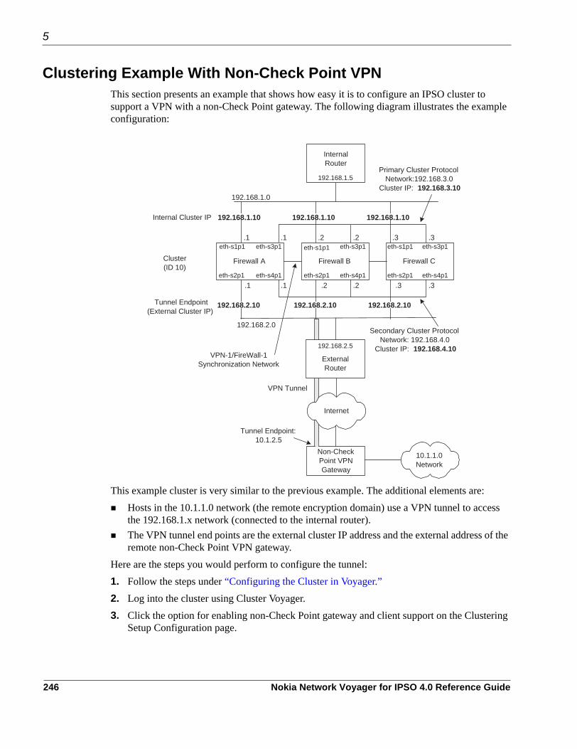
5
Clustering Example With Non-Check Point VPN This section presents an example that shows how easy it is to configure an IPSO cluster to support a VPN with a non-Check Point gateway. The following diagram illustrates the example configuration:
This example cluster is very similar to the previous example. The additional elements are:Hosts in the 10.1.1.0 network (the remote encryption domain) use a VPN tunnel to access the 192.168.1.x network (connected to the internal router).The VPN tunnel end points are the external cluster IP address and the external address of the remote non-Check Point VPN gateway.
Here are the steps you would perform to configure the tunnel:1. Follow the steps under “Configuring the Cluster in Voyager.”2. Log into the cluster using Cluster Voyager.3. Click the option for enabling non-Check Point gateway and client support on the Clustering
Setup Configuration page.
192.168.1.0
192.168.2.0Secondary Cluster Protocol
Network: 192.168.4.0Cluster IP: 192.168.4.10
Cluster(ID 10)
Primary Cluster ProtocolNetwork:192.168.3.0
Cluster IP: 192.168.3.10
.1 .1
.1 .1
Firewall B
eth-s1p1
eth-s2p1
eth-s3p1
eth-s4p1
Firewall C
eth-s1p1
eth-s2p1
eth-s3p1
eth-s4p1
.2
.2 .2
.2
.3 .3
.3 .3
Firewall A
eth-s1p1 eth-s3p1
eth-s4p1eth-s2p1
Internal Cluster IP
192.168.2.5
InternalRouter
192.168.1.5
Non-CheckPoint VPNGateway
VPN Tunnel
Tunnel Endpoint(External Cluster IP)
Tunnel Endpoint:10.1.2.5
ExternalRouter
Internet
192.168.2.5
10.1.1.0Network
192.168.2.10 192.168.2.10 192.168.2.10
192.168.1.10 192.168.1.10 192.168.1.10
VPN-1/FireWall-1Synchronization Network
246 Nokia Network Voyager for IPSO 4.0 Reference Guide

4. In the Add New VPN Tunnel section, enter 10.1.1.0 in the Network Address field. 5. In the Mask field, enter 24.6. In the Tunnel End Point field, enter 10.1.2.5.7. Click Apply.8. Click Save.9. Configure the same tunnel in NGX.For more information, see “Configuring NGX for Clustering” and the Check Point documentation.
Nokia Network Voyager for IPSO 4.0 Reference Guide 247

5
248 Nokia Network Voyager for IPSO 4.0 Reference Guide

6 Configuring SNMP
This chapter describes the Nokia IPSO implementation of Simple Network Management Protocol (SNMP) and how to configure it on your system.
SNMP OverviewThe Simple Network Management Protocol (SNMP) is the Internet standard protocol used to exchange management information between network devices. SNMP works by sending messages, called protocol data units (PDUs), to different parts of a network. SNMP-compliant devices, called agents, store data about themselves in Management Information Bases (MIBs) and return this data to the SNMP requesters.IPSO implements UCD-SNMP 4.0.1 as the base version of SNMP. Changes have been made to the base version to address security and other fixes. For more information on Net-SNMP, go to http://www.net-snmp.org.
CautionIf you use SNMP, Nokia strongly recommends that you change the community strings for security purposes. If you do not use SNMP, you should disable the community strings.
SNMP, as implemented on Nokia platforms, supports the following:GetRequest, GetNextRequest, GetBulkRequest, and a select number of traps. The Nokia implementation also supports SetRequest for three attributes only: sysContact,sysLocation, and sysName. You must configure a read-write community string to enable set operations.SNMP v1, v2, and v3. For more information about SNMP v3, see “Managing SNMP Users.”
NoteThe Nokia implementation of SNMPv3 does not yet support SNMPv3 traps.
Other public and proprietary MIBs as follows.
Nokia Network Voyager for IPSO 4.0 Reference Guide 249

6
MIB Source Function
Rate-Shape MIB proprietary Monitoring rate-shaping statistics and configuration. Monitoring system-specific parameters.
IPSO System MIB proprietary Defines the system MIB for IPSO. The IPSO chassis temperature, fan group, and power-supply group function only on certain firewalls.
IPSO Registration MIB proprietary Defines the object ID (OID) prefixes.
OID Registration MIB proprietary Defines the object ID (OID) prefixes.
Unit Types MIB proprietary Contains OID values for the different types of circuit cards used in Nokia equipment.
TCP MIB RFC 2012 Provides management information of TCP implementations.
EtherLike MIB RFC 1650 Generic objects for Ethernet-like network interfaces.
Host Resources MIB RFC 1514 Provides information about the system, such as hardware, software, processes, CPU utilization, disk utilization and so on.
IANAifType MIB IANA Defines the IANAifType textual convention, including the values of the ifType object defined in the MIB-II ifTable.
IF MIB RFC 2233 Describes generic objects for network interface sublayers
IP MIB RFC 2011 Provides management information for IP and ICMP implementations.
IP Forwarding MIB RFC 2096 Displays CIDR multipath IP routes.
ISDN MIB RFC 2127 Describes the management of ISDN interfaces.Note: The isdnMibCallInformation trap is not supported by IPSO.
VRRP MIB RFC 2787 Provides dynamic failover statistics.
RIP MIB RFC 1724 Describes RIP version 2 protocol.
SNMP Framework MIB RFC 2571 Outlines SNMP management architecture.
SNMP MPD MIB RFC 2572 Provides message processing and dispatching.
SNMP User-based SM MIB RFC 2574 Provides management information definitions for SNMP User-based Security Model
SNMPv2 MIB RFC 1907 Defines SNMPv2 entities. Note: The warmStart trap is not supported.
SNMPv2 SMI RFC 2578
250 Nokia Network Voyager for IPSO 4.0 Reference Guide

SNMPv2 TC RFC 854 Defines textual conventions for various values reported in OIDs and Traps.
Dial-Control MIB RFC 2128 Describes peer information for demand access and other kinds of interfaces.Note: The dialCtlPeerCallInformation and dialCtlPeerCallSetup traps are not supported by IPSO.
Entity MIB RFC 2737 Represents the multiple logical entities that a a single SNMP agent supports.IPSO does not support the entConfigChange trap is not supported by IPSO.
Tunnel-MIB RFC 2667 Provides statistics about IP tunnels.
UDP-MIB RFC 2013 Provides statistics about UDP implementations.
Frame Relay DTE MIB RFC 2115 Keeps statistics and errors in one or more circuits of a device implementing Frame Relay.
Token Ring MIB RFC 1748
Check Point MIB proprietary Statistics and version information on any firewalls currently installed.
1213 MIB RFC 1213 Contains the original definition of MIB-II. Nokia provides this MIB with the system to ensure backwards compatibility with SNMP v1.
IPSO-LBCluster-MIB proprietary Provides information about IPSO load- balancing systems.
HWM MIB proprietary Contains hardware management information.Note: IPSO does not send the traps that this MIB supports when the Nokia platform is used as an IP security device.
Nokia Common MIB OID Registration MIB
proprietary
Nokia Common NE Role MIB proprietary
Nokia Enhanced SNMP Solution Suite Alarm IRP MIB
proprietary Note: IPSO does not send traps that this MIB supports when the Nokia platform is used as an IP security device.
Nokia Enhanced SNMP Solution Suite Common Definition MIB
proprietary Note: IPSO does not send traps that this MIB supports when the Nokia platform is used as an IP security device.
Nokia Enhanced SNMP Solution Suite PM Common Definition MIB
proprietary
MIB Source Function
Nokia Network Voyager for IPSO 4.0 Reference Guide 251

6
Both the proprietary MIBs and the public MIBs are supplied with the system. To view more detailed information about the MIBs, see the /etc/snmp/mibs directory.
NoteThe SNMPv2-CONF MIB resides in the /etc/snmp/mibs/unsupported directory.
The SNMP agent implemented in Nokia IPSO enables an SNMP manager to monitor the device and to modify the sysName, sysContact and sysLocation objects only.
NoteYou must configure an SNMP string first to configure sysContact and sysLocation.
Use Network Voyager to perform the following tasks:Define and change one read-only community string. Define and change one read-write community string.Enable and disable the SNMP daemon.Create SNMP users.Modify SNMP user accounts.Add or delete trap receivers.Enable or disable the various traps.Enter the location and contact strings for the device.
SNMP Proxy Support for Check Point MIB IPSO supports the use of a proxy for SNMP GetRequest and SNMP GetNextRequest for Check Point objects. The following are guidelines and limitations you should be aware of.
Nokia Enhanced SNMP Solution Suite PM IRP MIB
proprietary Note: IPSO does not send traps that this MIB supports when the Nokia platform is used as an IP security device.
Nokia NE3S Registration MIB proprietary
Nokia Link Aggregation MIB proprietary Contains the traps required for managing link aggregation.
Nokia NTP MIB proprietary
SNMPv2-CONF IPSO does not support this MIB but it is included for those customers who need it to enable their management tools. This MIB resides in the /etc/snmp/mibs/unsupported directory.
MIB Source Function
252 Nokia Network Voyager for IPSO 4.0 Reference Guide

Using the Check Point MIBYou must use the Check Point version of the Check Point MIB (CP-MIB) text file in $FWDIR/lib/snmp of your network management tool. Do not use the CheckPoint-MIB.txt included in releases before Nokia IPSO 3.7.Whenever IPSO SNMPd is started or restarted, it searches for the CheckPoint-MIB.txt. The following is an example of a message you may see as a result of the search:IP650 [admin]# Jan 31 12:17:19 IP650 [LOG_ERR] snmpd: Cannot find module (CheckPoint-MIB) : At line 1 in (none)
You can ignore this message.Any SNMP requests to the CP-MIB when the Check Point SNMPd (CP-SNMPd) is not running time out. (The IPSO SNMPd does not respond.)The SNMP Proxy support is hard-coded to work only with the CP-SNMPd. It is not a generic proxy that you can use for accessing other MIBs. If you change the following default configurations, the SNMP Proxy for the CP-MIB does not work:
CP-SNMPd must continue to run on port 260.CP-SNMPd must continue to accept SNMPv1 and have a read community set to “public.” CP-SNMPd must continue to be accessible through “localhost” on the Nokia IPSO device.
The SNMP Proxy is not a trap proxy and only proxies SNMP Get and SNMP GetNext requests.When simultaneous SNMP queries arrive, the SNMP Proxy returns valid values to only one request.Because Nokia IPSO uses a proxy to support the Check Point MIB, reference the Check Point documentation for any limitations of the CP-SNMPd.
Using cpsnmp_startYou must run the cpsnmp_start script to make sure that CP-SNMPd is running on Check Point versions NG FP1, FP2, and FP3. You do this by first enabling the IPSO SNMPd from Nokia Network Voyager and then enabling the CP-SNMPd by using /bin/cpsnmp_start on the command line.
NoteWhenever you use the cprestart or cpstop;cpstart commands, you must run the cpsnmp_start script to restart the CP-SNMPd when you are using NG FP3.
NoteUsing FloodGate with Check Point NG FP1, FP2, and FP3 causes SNMP query operations to fail, even on non-FloodGate CheckPoint MIB objects. You must restart the CP-SNMPd to have SNMP query operations. On NG FP2, just disabling FloodGate might not enable
Nokia Network Voyager for IPSO 4.0 Reference Guide 253

6
SNMP query operations. In this case, you might have to delete the FloodGate package from your system.
Enabling SNMP and Selecting the VersionThe SNMP daemon is enabled by default. If you choose to use SNMP, configure it according to your security requirements. At minimum, you must change the default community string to something other than public. You should also select SNMPv3, rather than the default v1/v2/v3, if your management station supports it.
CautionIf you do not plan to use SNMP to manage the network, disable it. Enabling SNMP opens potential attack vectors for surveillance activity by enabling an attacker to learn about the configuration of the device and the network.
You can choose to use all versions of SNMP (v1, v2, and v3) on your system or to allow SNMPv3 access only. If your management station supports v3, select to use only v3 on your IPSO system. SNMPv3 limits community access; only requests from users with enabled SNMPv3 access are allowed and all other requests are rejected.
To enable or disable SNMP1. Choose SNMP under Configuration in the tree view.2. Select Yes or No for Enable SNMP Daemon.3. If you are enabling SNMP, click Apply.
The SNMP configuration options appear.
CautionTo run the Check Point and SNMP daemons simultaneously, you must start the Check Point SNMP daemon after you start VPN-1/Firewall NG. If you start the Check Point SNMP daemon before you start VPN-1FireWall-1 NG, the IPSO daemon does not start.
4. From the SNMP version drop-down list, select the version of SNMP to run: SNMPv1/v2/v3 Select this option if your management station does not support SNMPv3.SNMPv3 Select this option if your management station supports v3. SNMPv3 provides a higher level of security than v1 or v2.
5. If you selected v1/v2/v3, enter a new read-only community string under Community Strings. This is a basic security precaution that you should always take.
254 Nokia Network Voyager for IPSO 4.0 Reference Guide

NoteIf you select the Disable checkbox all community strings are disabled and SNMPv1 and v2 do not function. This has the same effect as selecting only SNMPv3 in the previous step.
6. (Optional). Set a read-write community string.
CautionSet a read-write community string only if you have reason to enable set operations, only if you enabled SNMPv3 (not v1/v2/v3), and if your network is secure.
7. Click Apply.8. Click Save to make your changes permanent.
Configuring the System for SNMPWhen you enable SNMP for your system, you can configure the following:
Specify an agent address. See “Setting an Agent Address” on page 255Configure traps. See “Configuring Traps” on page 256.
Setting an Agent AddressAn agent address is a specific IP address at which the SNMP agent listens and responds to requests. The default behavior is for the SNMP agent to listen to and respond to requests on all interfaces. If you specify one or more agent addresses, the system SNMP agent listens and responds only on those interfaces. You can use the agent address as another way to limit SNMP access. For example, you can limit SNMP access to one secure internal network that uses a particular interface by configuring that interface as the only agent address.
To set an SNMP agent address1. Choose SNMP under Configuration in the tree view.2. Enter the valid IP address of a configured interface in the Agent New Address field.
You can use the IP address of any existing and valid interface.3. Click Apply.
The IP address and a corresponding Delete check box appear.4. Click Save to make your change permanent.
Nokia Network Voyager for IPSO 4.0 Reference Guide 255

6
NoteIf no agent addresses are specified, the SNMP protocol responds to requests from all interfaces.
Configuring TrapsManaged devices use trap messages to report events to the network management station (NMS). When certain types of events occur, the platform sends a trap to the management station.Traps are defined in text files located in the /etc/snmp/mibs directory:
System traps are defined in the Nokia-IPSO-System-MIB. The ifLinkUpDown trap is defined in the IF-MIB. Clustering traps are defined in the Nokia-IPSO-LBCluster-MIB. Disk mirror traps are defined in the Nokia-IPSO-System-MIB.
Below is a list of the objects associated with individual traps.The systemTrapConfigurationChange, systemTrapConfigurationFileChange, and systemTrapConfigurationSaveChange traps are associated with the ipsoConfigGroup objects. These objects include ipsoConfigIndex, ipsoConfigFilePath, ipsoConfigFileDateAndTime, ipsoConfigLogSize, ipsoConfigLogIndex, and ipsoConfigLogDescr.The systemTrapDiskMirrorSetCreate, systemTrapDiskMirrorSetDelete, systemTrapDiskMirrorSyncFailure, and systemTrapDiskMirrorSyncSuccess traps are associated with the ipsoDiskMirrorGroup objects. These objects include ipsoTotalDiskMirrorSets, ipsoMirrorSetIndex, ipsoMirrorSetSourceDrive, ipsoMirrorSetDestinationDrive, ipsoMirrorSetSyncPercent.The linkUp and linkDown traps are associated with the ifIndex, ifAdminStatus, and ifOperStatus objects.Table 12 lists the types of SNMPv1 and SNMPv2 traps which IPSO supports.
NoteThe Nokia implementation of SNMPv3 does not yet support SNMPv3 traps.
Table 12 Types of SNMP Traps
Type of Trap Description
coldStart Supplies notification when the SNMPv2 agent is reinitialized.
linkUp/linkDown Supplies notification when one of the links, which is administratively up, either comes up or is lost.
256 Nokia Network Voyager for IPSO 4.0 Reference Guide

lamemberActive Supplies notification when a port is added to a link aggregation group.
lamemberInactive Supplies notification when a port is removed from a link aggregation group.
Authorization Supplies notification when an SNMP operation is not properly authenticated.Although all implementation of SNMPv2 must be capable of generating this trap, the snmpEnableAuthenTraps object indicates whether this trap is generated.
vrrpTrapNewMaster Supplies notification when a new VRRP master is elected.
vrrpTrapAuthFailure Supplies notification when an VRRP hello message is not properly authenticated.
systemTrapConfigurationChange Supplies notification when a different configuration file is selected.
systemTrapConfigurationFileChange Supplies notification when a different configuration file is selected.
systemTrapConfigurationSaveChange Supplies notification when a permanent change to the system configuration occurs.
systemTrapLowDiskSpace Supplies notification when space on the system disk is low.This trap is sent if the disk space utilization has reached 80 percent or more of its capacity. If this situation persists, a subsequent trap is sent after 15 minutes.
systemTrapNoDiskSpace Supplies notification when the system disk is full.This trap is sent if 2 percent or less of the disk space remains available, or if the remaining disk space is equal to or less than 1 MB. If this situation persists, a subsequent trap is sent after 15 minutes.
systemTrapDiskFailure Supplies notification when a particular disk drive fails.Note: The systemTrapDiskFailure applies only to Nokia platforms that support disk mirroring.
systemTrapDiskMirrorSetCreate Supplies notification when a system disk mirror set is created.
systemTrapMirrorSetDelete Supplies notification when a system disk mirror set is deleted.
systemTrapDiskMirrorSyncSuccess Supplies notification when a system disk mirror set is successfully synced.
Table 12 Types of SNMP Traps
Type of Trap Description
Nokia Network Voyager for IPSO 4.0 Reference Guide 257

6
To configure traps, specify the following information:The location of the trap receiver (management station). See “Configuring Trap Receivers” on page 259.Which types of traps to enable. See “Enabling or Disabling Trap Types” on page 259.An agent address to be included in each trap message sent to the management station to identify which network device generated the trap. See “Setting the Trap PDU Agent Address” on page 259.Location and contact information provided to the management system about where your device is located and who to contact about it. See “Configuring Location and Contact Information” on page 260.
systemTrapDiskMirrorSyncFailure Supplies notification when a system disk mirror set fails during syncing.Note: The disk mirror traps are supported only on systems where disk mirroring is supported.
clusterMemberReject Supplies notification when a member request to join a cluster is rejected.
clusterMemberJoin Supplies notification when a member node joins the cluster.
clusterMemberLeft Supplies notification when a member node leaves the cluster.
clusterNewMaster Supplies notification when a cluster is formed and a new master is elected.
clusterProtocolInterfaceChange Supplies notification when a failover occurs from the primary cluster network to the secondary cluster network.
systemPowerSupplyFailure Supplies notification when a power supply for the system fails.Note: For the IP2250, this trap is also sent if one of the power supplies is switched off. This trap includes the power supply index and is supported only on platforms with two power supplies installed and running.
systemFanFailure Supplies notification when a CPU or chassis fan fails. This trap includes the fan index.
SystemOverTemperature Supplies notification when a power supply failure occurs because of high temperature.This trap is followed by a power supply failure trap that specifies the power supply index that failed. This trap is supported only on platforms with two power supplies installed and running
systemSnmpProcessShutdown Supplies notification when the status of the SNMP daemon is changed, either turned off or turned on.
Table 12 Types of SNMP Traps
Type of Trap Description
258 Nokia Network Voyager for IPSO 4.0 Reference Guide

Configuring Trap ReceiversYou must specify the management station that accepts traps from your appliance, and the community string used on your management station (receiver) to control access.
To configure trap receivers1. Choose SNMP under Configuration in the tree view. 2. Enter the IP address (or the hostname if DNS is set) of a receiver in the Add New Trap
Receiver text field.3. Enter the community string for the specified receiver in the Community String for new Trap
Receiver field. 4. Select the Trap SNMP Version for the trap receiver in the drop-down menu.
The options are v1 or v2, and the default is v1. This is the version of SNMP used by your management station.
5. Click Submit.
Enabling or Disabling Trap TypesWhen you enable types of traps, the system sends a trap message when that type of event occurs. For example, if you enable authorization traps, the system sends a trap message to the management station when it receives a packet with an incorrect community string.
To enable or disable traps1. Choose SNMP under Configuration in the tree view. 2. To enable any type of trap, click On next to the name of the trap and click Apply.3. To disable any type of trap, click Off next to the name of the trap and click Apply.4. To make your changes permanent, click Save.
Setting the Trap PDU Agent AddressThe trap PDU address is included in the protocol data unit (PDU) of each trap message sent to the management station that uses it to identify which network device generated the trap.This address must belong to a configured interface. If you do not configure an agent address for traps, the system identifies the trap agent address as 0.0.0.0 in SNMP traps (in accordance with RFC 2089). (For releases of Nokia IPSO previous to 3.7, the default was to use the IP address of the first valid interface.)
To set the trap PDU agent address1. Choose SNMP under Configuration in the tree view.2. To specify the IP address to be used for sent trap PDU, enter the IP address in the Trap PDU
Agent Address field.3. Click Apply.
Nokia Network Voyager for IPSO 4.0 Reference Guide 259

6
4. Click Save to make your changes permanent.
Configuring Location and Contact InformationThe settings for location and contact information provide information to the management system about where your device is located and who to contact about it.Set the location and contact strings when you perform the initial configuration for SNMP on your system.
To configure location and contact information1. Choose SNMP under Configuration in the tree view.2. In the SNMP Location String text field, enter the actual location of the device. Click Apply.3. In the SNMP Contact String text field, enter the name of department or person who has
administrative responsibility for the device. 4. Click Apply.5. Click Save to make your changes permanent.
Interpreting Error MessagesThis section lists and explains certain common error status values that can appear in SNMP messages. Within the PDU, the third field can include an error-status integer that refers to a specific problem. The integer zero (0) means that no errors were detected. When the error field is anything other than 0, the next field includes an error-index value that identifies the variable, or object, in the variable-bindings list that caused the error.The following table lists the error status codes and their corresponding meanings.
Error status code Meaning Error status code Meaning
0 noError 10 wrongValue
1 tooBig 11 noCreation
2 NoSuchName 12 inconsistentValue
3 BadValue 13 resourceUnavailable
4 ReadOnly 14 commitFailed
5 genError 15 undoFailed
6 noAccess 16 authorizationError
7 wrongType 17 notWritable
8 wrongLength 18 inconsistentName
260 Nokia Network Voyager for IPSO 4.0 Reference Guide

NoteYou might not see the codes. The SNMP manager or utility interprets the codes and displays and logs the appropriate message.
The subsequent, or fourth field, contains the error index when the error-status field is nonzero, that is, when the error-status field returns a value other than zero, which indicates that an error occurred. The error-index value identifies the variable, or object, in the variable-bindings list that caused the error. The first variable in the list has index 1, the second has index 2, and so on. The next, or fifth field, is the variable-bindings field. It consists of a sequence of pairs; the first is the identifier. The second element is one of the following five: value, unSpecified, noSuchOjbect, noSuchInstance, and EndofMibView. The following table describes each element.
GetRequestThe following table lists possible value field sets in the response PDU or error-status messages when performing a GetRequest.
9 wrongEncoding
Error status code Meaning Error status code Meaning
Variable-bindings element Description
value Value associated with each object instance; specified in a PDU request.
unSpecified A NULL value is used in retrieval requests.
noSuchObject Indicates that the agent does not implement the object referred to by this object identifier
noSuchInstance Indicates that this object does not exist for this operation.
endOfMIBView Indicates an attempt to reference an object identifier that is beyond the end of the MIB at the agent.
Value Field Set Description
noSuchObject If a variable does not have an OBJECT IDENTIFIER prefix that exactly matches the prefix of any variable accessible by this request, its value field is set to noSuchObject.
noSuchInstance If the variable's name does not exactly match the name of a variable, its value field is set to noSuchInstance.
Nokia Network Voyager for IPSO 4.0 Reference Guide 261

6
GetNextRequestThe only values that can be returned as the second element in the variable-bindings field to a GetNextRequest when an error-status code occurs are unSpecified or endOfMibView.
GetBulkRequestThe GetBulkRequest minimizes the number of protocol exchanges by letting an SNMPv2 manager request that the response be as large as possible given the constraints on the message size.The GetBulkRequest PDU has two fields that do not appear in the other PDUs: non-repeaters and max-repetitions. The non-repeaters field specifies the number of variables in the variable-bindings list for which a single-lexicographic successor is to be returned. The max-repetitions field specifies the number of lexicographic successors to be returned for the remaining variables in the variable-bindings list.If at any point in the process, a lexicographic successor does not exist, the endofMibView value is returned with the name of the last lexicographic successor, or, if there were no successors, the name of the variable in the request.If the processing of a variable name fails for any reason other than endofMibView, no values are returned. Instead, the responding entity returns a response PDU with an error-status of genErr and a value in the error-index field that is the index of the problem object in the variable-bindings field.
Configuring SNMPv3IPSO supports the user-based security model (USM) component of SNMPv3 to provide message-level security. With USM (described in RFC 3414), access to the SNMP service is controlled on the basis of user identities. Each user has a name, an authentication pass phrase (used for identifying the user), and an optional privacy pass phrase (used for cryptographically protecting against disclosure of SNMP message payloads). The system uses the MD5 hashing algorithm to provide authentication and integrity protection and DES to provide encryption (privacy). Nokia recommends that you use both authentication
genErr If the processing of a variable fails for any other reason, the responding entity returns genErr and a value in the error-index field that is the index of the problem object in the variable-bindings field.
tooBig If the size of the message that encapsulates the generated response PDU exceeds a local limitation or the maximum message size of the request’s source party, then the response PDU is discarded and a new response PDU is constructed. The new response PDU has an error-status of tooBig, an error-index of zero, and an empty variable-bindings field.
Value Field Set Description
262 Nokia Network Voyager for IPSO 4.0 Reference Guide

and encryption, but you can employ them independently by specifying one or the other with your SNMP manager requests. The IPSO system responds accordingly.
NoteNokia systems do not protect traps with authentication or encryption.
Request MessagesYou must configure your SNMP manager to specify the security you want. If you are using a UCD-SNMP/Net-SNMP based manager, here are the security-related options you can use in request messages:
For example, to send an snmpwalk request from your manager with full protection, you would enter the following command:snmpwalk -v 3 -u username -a MD5 -A password -x DES -X password -l authPriv system_name OID
For more information about USM, see RFC 3414.
Managing SNMP UsersSNMP users are maintained separately from system users. You can create SNMP user accounts with the same names as existing user accounts or different. You can create SNMP user accounts that have no corresponding system account. When you delete a system user account, you must separately delete the SNMP user account.
Table 13 Security Related Options Used in Request Messages
Option Description
-u name Specifies the user name.
-a MD5 Use MD5 hashing for authentication.
-x DES Use DES for encryption.
-A passwordSpecifies the user’s password/passphrase. Use for authentication. The password/passphrase must have at least 8 characters.
-X passwordSpecifies the user’s password/passphrase. Use for encryption. The password/passphrase must have at least 8 characters.
-l [authNoPriv | authPriv | authPrivReq]
Specifies the security level:• authNoPriv: use authentication only• authPriv: use authentication and encryption is enabled• authPrivReq: use authentication and encryption is required
Nokia Network Voyager for IPSO 4.0 Reference Guide 263

6
To view existing SNMP users, click SNMP under Configuration > System Configuration in the tree view and click Manage SNMP Users. Alternatively, you can click the Manage SNMP User Access link located on the Configuration > Security and Access > Users page.The admin user or a user with privileges for the SNMP feature can modify the security level, authentication pass phrase, and privacy pass phrase for existing SNMP users, and create or delete SNMP users. Pass phrases differ from passwords only in length—pass phrases are usually much longer than passwords. Their greater length makes pass phrases more secure.The IPSO implementation of SNMP supports DES and MD5 authentication to automatically generate USM keys. SNMP must be enabled on the system before you can set an SNMP user authentication or privacy pass phrase.
NoteIf you change the security level from either authPriv or authPrivReq to authNoPriv, the privacy pass phrase is automatically deleted. If you change it back to authNoPriv, you must supply a privacy pass phrase.
To add an SNMP user1. Click SNMP under Configuration in the tree view. 2. Click Manage USM Users.3. Enter the following information for the new user:
User Name—The range is 1 to 31 alphanumeric characters with no spaces, backslash, or colon characters. This can be the same as a user’s name for system access, though the SNMP user account is handled as a separate entity.Security Level. Select from the following:
Authentication + Privacy—The user has authentication and privacy pass phrases and can connect with or without privacy encryption. Authentication, no privacy—The user has only an authentication pass phrase and can connect only without privacy encryption. Authentication and privacy required—The user must connect using both authentication and encryption pass phrases.
Authentication Pass Phrase—Used to identify the user. Enter a password for the user that is between 8 and 128 characters in length.Privacy Pass Phrase—Used to cryptographically protect against disclosure of SNMP message payloads. Enter a pass phrase that is between 8 and 128 characters in length.
4. Click Apply.An entry for the new user appears in the SNMP USM Users table.
5. Click Save to make your changes permanent.
264 Nokia Network Voyager for IPSO 4.0 Reference Guide

To delete a USM user 1. Click SNMP under Configuration in the tree view. 2. Click Manage USM Users at the bottom of the page.
The Manage SNMP Users page appears.3. Select the appropriate Delete check box.4. Click Apply.5. Click Save to make your changes permanent.
Nokia Network Voyager for IPSO 4.0 Reference Guide 265

6
266 Nokia Network Voyager for IPSO 4.0 Reference Guide

7 Configuring IPv6
This chapter describes the IPv6 features supported by Nokia IPSO and how to configure them on your system.
IPv6 OverviewIPv6 is the next generation IP protocol and is expected to replace IPv4, the current IP protocol. The Internet Engineering Task Force (IETF) formally began to work on the new protocol in 1994. IPv6 enhances IPv4 in many ways including:
Expanded addressing capabilitiesSimplified header formatImproved support for extensions and optionsFlow-labeling capabilityPlug and play autoconfiguration
The IPv6 implementation includes basic features specified in IPv6 RFCs and features that support IPv6-capable hosts in a network. IPv6 includes a transition mechanism that allows users to adopt and deploy IPv6 in a diffuse way and provides direct interoperability between IPv4 and IPv6 hosts.IPSO supports the following features as specified in the corresponding RFCs:
IPv6 Specification (RFC 2460)ICMP v6 (RFC 2463)Neighbor Discovery (RFC 2461, router only)Basic IPv6 Socket Interface (RFC 2553), except the following features:
Compatibility with IPv4 nodesTranslation of nodename to addressTranslation of address to nodenameSocket address structure to nodename and service name
IPv6 Addressing Architecture (RFC 2373)IPv6 Aggregatable Global Unicast Address Format (RFC 2374)IPv6 UDP supportIPv6 TCP support
Nokia Network Voyager for IPSO 4.0 Reference Guide 267

7
IPv6 over IPv4 Tunnel (RFC 2185)IPv6 over Ethernet (RFC 2464)IPv6 over FDDI (RFC 2467)IPv6 over PPP (RFC 2472)IPv6 over ATM (RFC 2492, PVC only)IPv6 over ARCNET (RFC 2497)IPv6 over Token Ring (RFC 2470)IPv6 over IPv4 (RFC 2529)IPv6 to IPv4 (Internet Draft)Generic Packet Tunneling (RFC 2473, IPv4 through IPv6 only)RIPng for IPv6Static RoutesRoute AggregationRoute RedistributionIPv6 inetdIPv6 telnet client and serverIPv6 FTP client and serverUtilities (ping, netstat, tcpdump, ndp)
InterfacesTo configure IPv6 logical interfaces1. Click IPv6 Interfaces under Configuration > System Configuration > IPv6 Configuration in
the tree view. 2. Click the logical interface link to configure in the Logical column. Example: eth-s1p1c03. Enter the IP address prefix in the New IP Address text box and the mask length (in bits) in
the New Mask Length text box. The default mask length is 64.
4. Click Apply.5. Click Save to make your changes permanent.6. Click Up at the top of the page to take you back to the IPv6 Logical Interfaces page.7. To enable the IPv6 address, click On in the IPv6 Active field.8. Click Apply.9. Click Save to make your change permanent.
268 Nokia Network Voyager for IPSO 4.0 Reference Guide

To delete an IPv6 address1. Click IPv6 Interfaces under Configuration > System Configuration > IPv6 Configuration in
the tree view. 2. Click the logical interface link to configure in the Logical column for which you want to
delete an IPv6 address. Example: eth-s1p1c03. Check the delete box next to the IPv6 address you want to delete.4. Click Apply.5. Click Save to make your changes permanent.
To disable IPv6 on an interface1. Click IPv6 Interfaces under Configuration > System Configuration > IPv6 Configuration in
the tree view. 2. Click Off in the IPv6 active field next to the name of that interface.
NoteYou cannot disable an IPv6 interface configured for a virtual router when the router is in the master state. If you try to disable the interface when the router is in the master state, Network Voyager displays an error message. To disable the IPv6 interface, you must first delete the interface as a VRRP virtual address. You can, however, disable an IPv6 interface enabled on a virtual router when the router is in a backup state.
3. Click Apply.The list of addresses in the IPv6 address field for the specified logical interface disappear.
4. Click Save to make your changes permanent.
To configure neighbor discovery1. Click Neighbor Discovery under Configuration > System Configuration > IPv6
Configuration in the tree view. 2. In the Global Neighbor Discovery Settings field, enter the value for the queue limit in the
Queue Limit text box. This value represents the maximum number of output packets to be queued while the link-layer destination address is being resolved.
3. In the Global Neighbor Discovery Settings field, enter the value for the unicast retry limit in the Unicast Retry Limit text box. This value represents the number of times to retry Unicast Neighbor Discovery requests.
4. In the Global Neighbor Discovery Settings field, enter the value for the multicast retry limit in the Multicast Retry Limit text box. This value represents the number of times to retry Multicast Neighbor Discovery requests.
5. In the Global Neighbor Discovery Settings field, enter the value for the duplicate address detection retry limit in the Duplicate Address Detection Retry Limit text box. This value
Nokia Network Voyager for IPSO 4.0 Reference Guide 269

7
represents the number of times to retry Duplicate Address Detection Neighbor Discovery requests.
6. In the Permanent Neighbor Discovery Entries field, enter the permanent IPv6 address for the permanent neighbor discovery destination in the New Permanent Neighbor Discovery Entry text box.
7. Click Apply.8. Click Save to make your changes permanent.9. To flush current dynamic Neighbor Discovery entries, click Flush in the Dynamic Neighbor
Discovery Entries field.10. Click Apply.
IPv6 and IPv4 Compatibility
Configuring IPv6 in IPv4 TunnelsIf your IPv6 traffic needs to travel through IPv4 networks to reach its destination, you need to set up a virtual link by configuring a tunnel.
To configure IPv6 in IPv4 tunnels1. Click IPv6 in IPv4 Tunnels under Configuration > System Configuration > IPv6
Configuration in the tree view. 2. Enter the IPv4 address of the local tunnel endpoint in the Local IPv4 Address text box.3. Enter the IPv4 address of the remote tunnel endpoint in the Remote IPv4 Address text box.
NoteThe local address must be the address of another interface configured for the router.
4. (Optional) Enter the IPv6 link-local address of the local tunnel endpoint in the Local IPv6 Link Local text box. If you do not specify an address a default will be configured.
5. (Optional) Enter the remote IPv6 link-local address of the remote tunnel endpoint in the Remote IPv6 Link Local text box.
6. (Optional) Enter a value in the Time to Live text box for the Time to Live (TTL) packets sent on the tunnel.
7. Click Apply.8. Click Save to make your changes permanent.
270 Nokia Network Voyager for IPSO 4.0 Reference Guide

Configuring IPv6 to IPv4This feature allows you to connect an IPv6 domain through IPv4 clouds without configuring a tunnel.
To configure IPv6 to IPv41. Click IPv6 to IPv4 under Configuration > System Configuration > IPv6 Configuration in the
tree view. 2. In the Enable IPv6 to IPv4 field, click Yes.3. In the Active field, just below the Logical Interface field, click On to enable the logical
interface. This value represents the pseudo-interface that is associated with this feature. It does not correspond to a specific physical device.
4. Enter the IPv4 address of the local interface in the Local IPv4 Address text box.
NoteThis address must be the address of another interface configured for the router.
5. (Optional) Enter a valuefor the Time to Live (TTL) packets sent. 6. Click Apply.7. Click Save to make your changes permanent.
Configuring IPv6 over IPv4This feature allows you to transmit IPv6 traffic through IPv4 domains without configuring a tunnel.
To configure IPv6 over IPv41. Click IPv6 over IPv4 Tunnels under Configuration > System Configuration > IPv6
Configuration in the tree view. 2. In the Enable IPv6 over IPv4 field, click Yes.3. In the Active field, just below the Logical Interface field, click On.
This value represents the pseudo-interface that is associated with this feature. It does not correspond to a specific physical device
4. Enter the IPv4 address of the local interface in the Local IPv4 Address text box.
NoteThis address must be the address of another interface configured for the router.
5. (Optional) Enter a value in the for the Time to Live (TTL) packets sent.
Nokia Network Voyager for IPSO 4.0 Reference Guide 271

7
6. Click Apply.7. Click Save to make your changes permanent.
Configuring IPv4 in IPv6 TunnelsThis feature allows you to set up a point-to-point link to permit traffic from IPv4 domains to travel through IPv6 domains.
To configure IPv4 in IPv6 tunnels1. Click IPv6 in IPv4 Tunnels under Configuration > System Configuration > IPv6
Configuration in the tree view. 2. Enter the IPv6 address of the local tunnel endpoint in the Local IPv6 Address text box.3. Enter the IPv6 address of the remote tunnel endpoint in the Remote IPv6 Address text box.4. (Optional) Enter a value in the Hop Limit text box for the maximum number of hops the
packets sent on the tunnel can take to reach their destination.5. Click Apply.
6. Click Save to make your changes permanent.
Configuring an IPv6 Default or Static Route
To configure an IPv6 default or static route1. Click IPv6 Static Routes under Configuration > System Configuration > IPv6
Configuration > Routing Configuration in the tree view. 2. To enable a default route:
a. Select On in the Default field. b. Click Apply.
3. To create a new static route:a. Enter the IPv6 address prefix in the New Static Route text box.b. Enter the mask length (number of bits) in the Mask Length text box.c. Click Apply.
4. Select the type of next hop the route will take from the Next Hop Type drop-down list—Normal, Reject, or Black Hole.
5. Select the interface that the route will use to reach the gateway in the Interface field.
NoteThis interface must be specified only if the gateway is a link local address.
272 Nokia Network Voyager for IPSO 4.0 Reference Guide

6. To specify the order in which next hops are selected, enter a value from one to eight in the Preference text box. The lower the value the more preferred the link. The next preferred value is selected as the next hop only when an interface fails. A non-reachable link is not selected as the next hop.The preference option also supports equal-cost multipath routing. For each preference value, you can configure as many as eight gateway addresses. The nexthop gate address for each packet to the destination is selected based on the nexthop algorithm that is configured.
7. Click Apply.8. Click Save to make your changes permanent.
Routing Configuration
Configuring OSPFv3IPSO supports OSPFv3, which supports IPv6 addressing and is based on RFC 2740. OSPFv3 has essentially the same configuration parameters as OSPFv2, except that you enter them from the Network Voyager page that you access by clicking Routing Configuration under Configuration > System Configuration > IPv6 Configuration in the tree view. For more information, see “OSPF” on page 353.
Configuring RIPng1. Click RIPng under Configuration > System Configuration > IPv6 Configuration > Routing
Configuration in the tree view. 2. To enable RIPng, click On next to the logical interface on which you want to run RIP, and
then click Apply.3. Enter a value in the Metric text box for the RIPng metric to be added to routes that are sent
by way of the specified interface.4. Click Apply.5. Click Save to make your changes permanent.
Creating IPv6 Aggregate Routes1. Click IPv6 route Aggregation under Configuration > System Configuration > IPv6
Configuration > Routing Configuration in the tree view. 2. Enter the IPv6 prefix for the new aggregate route in the Prefix for New Aggregate text box.3. Enter the mask length (number of bits) in the Mask Length text box.4. Click Apply.
Nokia Network Voyager for IPSO 4.0 Reference Guide 273

7
5. Scroll through the New Contributing Protocol List click the protocol you want to use for the new aggregate route.
6. Click Apply.7. Click Save to make your changes permanent.8. Click On in the Contribute All Routes from <Protocol> field.9. (Optional) To specify an IPv6 prefix, enter the IPv6 address and mask length in the text
boxes in the Prefix for New Contributing Route from <Protocol> field.10. Click Apply, and click Save to make your changes permanent.
Creating Redistributed Routes
Redistributing Static Routes into RIPng1. Click IPv6 Route Redistribution under Configuration > System Configuration > IPv6
Configuration > Routing Configuration in the tree view. 2. Click Static Routes.3. To redistribute all currently valid static routes into RIPng, click the On button in the
Redistribute All Statics in the RIPng field.4. Enter a value in the Metric text box for the metric cost that the created RIPng routes will
have.5. Click Apply.6. Click Save to make your changes permanent.7. To redistribute a specific static route or routes into RIPng, click On next to the IPv6 interface
for the static route to redistribute to RIPng.8. Enter a value in the Metric text box for the metric cost that the created RIPng route(s) will
have. 9. Click Apply.10. Click Save to make your changes permanent.
Redistributing Aggregate Routes in RIPng1. Click IPv6 Route Aggregation under Configuration > System Configuration > IPv6
Configuration > Routing Configuration in the tree view. 2. To redistribute all currently valid aggregate routes into RIPng, click On in the Redistribute
all Aggregates into RIPng field.3. Enter a value in the Metric text box for the metric cost that the created RIPng routes will
have 4. Click Apply.5. Click Save to make your changes permanent.
274 Nokia Network Voyager for IPSO 4.0 Reference Guide

6. To redistribute a specific aggregate route or routes into RIPng, click On next to the IPv6 interface for the aggregate route to redistribute into RIPng.
7. Enter a value in the Metric text box for the metric cost that the created RIPng route will have.
8. Click Apply.9. Click Save to make your changes permanent.
Redistributing Interface Routes into RIPng1. Click IPv6 Route Redistribution under Configuration > System Configuration > IPv6
Configuration > Routing Configuration in the tree view. 2. Click Interface Routes.3. To redistribute all currently active interface routes into RIPng, click On in the Export all
Interfaces into RIPng field.4. Enter a value in the Metric text box for the metric cost that the created RIPng routes will
have.5. Click Apply.6. Click Save to make your changes permanent.7. To redistribute a specific interface route or routes into RIPng, click On next to the IPv6
interface for the route to redistribute into RIPng.8. Enter a value in the Metric text box for the metric cost that the created RIPng routes will
have. 9. Click Apply.10. Click Save to make your changes permanent.
Router Discovery
Configuring ICMPv6 Router DiscoveryThe ICMPv6 Router Discovery Protocol allows hosts running an ICMPv6 router discovery client to locate neighboring routers dynamically as well as to learn prefixes and configuration parameters related to address autoconfiguration. Nokia implements only the ICMPv6 router discovery server portion, which means that the Nokia platform can advertise itself as a candidate default router, but it will not adopt a default router using the router discovery protocol.Beginning with IPSO 3.8.1 and as part of the new support of VRRP for IPv6 interfaces, only the router in a VRRP master state sends router discovery advertisements, and the advertisements are sent with the virtual IP address as the source address and the virtual MAC address as the MAC address. Routers in a VRRP backup state do not send router discovery advertisements. When VRRP failover occurs, the new master begins to send out router discovery advertisements. For
Nokia Network Voyager for IPSO 4.0 Reference Guide 275

7
more information about configuring VRRP for IPv6 interfaces, see “Configuring VRRP for IPv6.”1. Click ICMPv6 Router Discovery under Configuration > System Configuration > IPv6
Configuration > Router Services in the tree view. 2. To enable ICMPv6 router discovery, click On next to the interface on which you want to run
the protocol.3. Click Apply.4. (Optional) To enable the managed address configuration flag in the router advertisement
packet, click Yes in the Managed Config Flag field. This flag enables hosts to perform stateful autoconfiguration to obtain addresses.
5. (Optional) To enable the other stateful configuration flag in the router advertisement packet, click Yes in the Other Config Flag field. This flag enables hosts to perform stateful autoconfiguration to obtain information other than addresses.
6. (Optional) To enable the MTU options field in the router advertisement packet, click Yes in the Send MTU Option field.
7. (Optional) Enter a value (in seconds) in the Min Adv Interval text box for the minimum time between which unsolicited multicast ICMPv6 router advertisements are sent on the interface.
8. (Optional) Enter a value (in seconds) in the Max Adv Interval text box for the maximum time between which unsolicited multicast ICMPv6 router advertisements are sent on the interface in the Max Adv Interval text box.Whenever an unsolicited advertisement is sent, the timer is set to a value between the maximum advertisement interval and the minimum advertisement interval.
9. (Optional) Enter a value (in seconds) in the Router Lifetime text box for a router advertisement packets router lifetime field. A value of zero indicates that the router is not to be used as a default router.
10. (Optional) Enter a value in the Reachable Time text box for the router advertisement packets reachable time field. The value represents the time that a node assumes a neighbor is reachable after having received a reachability confirmation.
11. (Optional) Enter a value (in seconds) in the Retransmission Timer text box for the router advertisement packets retransmission timer field This value represents the time between which neighbor solicitation messages are retransmitted if the node doesn’t receive a response.
12. (Optional) Enter a value in the Cur Hop Limit text box for the router advertisement packets hop limit field
13. (Optional) To specify that the IPv6 prefix can be used for on-link determination, click Yes in the Onlink Flag field.
276 Nokia Network Voyager for IPSO 4.0 Reference Guide

14. (Optional) To specify that the IPv6 prefix can be used for autonomous address configuration, click Yes in the Autonomous Flag field.
15. (Optional) Enter a value (in seconds) in the Prefix Valid Lifetime text box for the prefix information options valid lifetime field. This value represents the length of time—relative to the time the packet is sent—that the prefix is valid for the purpose of on-link determination.
16. (Optional) Enter a value (in seconds) in the Prefix Preferred Lifetime text box for the prefix information options preferred lifetime field. This value represents the length of time—relative to the time the packet is sent—that addresses that are generated by the prefix through stateless autoconfiguration remain preferred.
17. Click Apply.18. Click Save to make your changes permanent.
VRRP for IPv6
Configuring VRRP for IPv6Beginning with IPSO 3.8.1, Nokia supports VRRP configuration for IPv6 interfaces. Nokia supports VRRP version 3, which is based on VRRP version 2 as defined for IPv4 in RFC 3768, and Monitored Circuit. Unlike VRRP version 2, VRRP version 3 does not support authentication, and the advertisement interval in the VRRP packet is 12 bits rather than eight bits. Also, for both VRRP version 3 and Monitored Circuit for IPv6 interfaces, the hello interval is measured in centiseconds rather than seconds. In version 3, the first address in the packet must be an IPv6 link-local address. For general information about VRRP, see “Virtual Router Redundancy Protocol (VRRP)” on page 183.For more information about how to configure Check Point NG with Application Intelligence for VRRP for IPv6 see, “Configuring Check Point NGX for VRRP” on page 197
NoteCheck Point NG with Application Intelligence does not support user, session, or client authentication for IPv6 interfaces.Also, Check Point NG does not support state synchronization for IPv6 interfaces. When a master router of a VRRP pair fails, and the backup router becomes the new master, all previously established connections are lost because state synchronization does not occur.
As part of the new support of VRRP for IPv6 interfaces, only the router in a VRRP master state sends router discovery advertisements, and the advertisements are sent with the virtual IP address as the source address and the virtual MAC address as the MAC address. Routers in a VRRP backup state do not send router discovery advertisements. When VRRP failover occurs,
Nokia Network Voyager for IPSO 4.0 Reference Guide 277
7
the new master begins to send out router discovery advertisements. For more information about configuring Router Discovery for IPv6 interfaces, see “Configuring ICMPv6 Router Discovery.”
Creating a Virtual Router for an IPv6 Interface Using VRRPv3You must configure a virtual router on an interface to enable other routers to back up its addresses.1. Click VRRP for IPv6 under Configuration > System Configuration > IPv6
Configuration > Router Services in the tree view. 2. Click VRRPv3 button next to the interface for which to enable VRRP. 3. Click Apply.4. Enter a value from 1 to 255 in the Own VRID text box to specify a virtual router ID for the
virtual router. Click Apply. Additional configuration options appear on the Network Voyager page after you click Apply.
NoteOther routers on the LAN use the virtual router ID to back up the he addresses of this router. No other router on the LAN can use this value to configure VRRP for its own addresses.
5. From the Address drop-down list select an IP address to specify a virtual IPv6 address for the virtual router. Click Apply.You must configure at least one virtual address, and at least one virtual IPv6 address must be the link-local address for the interface.To remove a virtual IP address, click off next to the entry for the IPv6 address.
6. (Optional) In the Hello Interval text box, enter a value from 1 to 4095 to specify the interval, in centiseconds, that is, 1 one-hundredth of a second, between VRRP advertisement transmissions. This value should be the same on all the routers with this virtual router configured.The default is 100 centiseconds, that this 1 second.
7. Click Apply.8. To make your changes permanent, click Save.
Creating a Virtual Router to Back Up Another VRRP Router Addresses Using VRRPv3
NoteDo not turn on the VRRP backup router before the VRRP master is configured. This leads to a service outage because the VRRP backup router takes over the IP address while the master is still active with that IP address. To configure the master router, see “Creating a Virtual Router for an IPv6 Interface Using VRRPv3.”
278 Nokia Network Voyager for IPSO 4.0 Reference Guide

Use this procedure to configure virtual routers to back up the addresses of other routers on a shared media network.1. Click VRRP for IPv6 under Configuration > System Configuration > IPv6
Configuration > Router Services in the tree view. 2. Click VRRPv3 button next to the interface for which to enable VRRP. 3. Click Apply.4. In the Backup Router with VRID text box, enter a value of from 1 to 255 to specify a virtual
ID for the virtual router used to back up the IP addresses of another system. The router you are backing up must also have this virtual router configured for its addresses. Click Apply.Additional configuration options appear that let you enter the IPv6 addresses of the router you are backing up.
5. (Optional) Enter a value from 1 to 254 in the Priority text box to specify the priority of this router during contention for the IP addresses of a failed router. Of the routers backing up the failed router, the one with the priority of highest value take overs the addresses.The default value is 100.
6. (Optional) In the Hello Interval text box, enter a value from 1 to 4095 to specify the interval, in centiseconds, that is, 1 one-hundredth of a second, between VRRP advertisement transmissions. This value should be the same on all the routers with this virtual router configured.The default is 100 centiseconds, that is, 1 second.
7. (Optional) Click Disabled next to Preempt Mode if you do not want a virtual router with a higher priority to preempt the current master router and become the new master. The default value is Enabled, which means that a virtual router with a higher priority than the current master preempts the master and becomes the new master router.
8. (Optional) Click Enabled next to Accept Mode if you want the virtual router when it is in a master state to accept and respond to IP packets sent to virtual IPv6 addresses. The VRRP protocol specifies not to accept or respond to such IP packets, so the default is Disabled.
9. Enter an IPv6 address for this virtual router in the Backup Address text box. The first back-up address you configure must be a link-local address. Any link-local address must belong to the fe80::/64 subnet, and global addresses must belong to the subnet of the interface.
10. (Optional) If the router you are backing up had more than one IP address, repeat step 10.11. Click Apply, and then click Save to make your changes permanent.
Monitoring the Firewall StateYou can configure the system to monitor the state of the firewall and respond appropriately. If a VRRP master detects that the firewall is not ready to handle traffic or is not functioning properly, the master fails over to a backup system. If all the firewalls on all the systems in the VRRP group are not ready to forward traffic, no traffic will be forwarded.
Nokia Network Voyager for IPSO 4.0 Reference Guide 279

7
This option does not affect the functioning of your system if a firewall is not installed.1. Click VRRP for IPv6 under Configuration > System Configuration > IPv6
Configuration > Router Services in the tree view. 2. Click Enabled in the Monitor Firewall State field.3. To disable this option, if you have enabled it, click Disabled.
The default is Enabled.4. Click Apply, and then click Save to make your changes permanent.
Setting a Virtual MAC Address for a Virtual RouterThis feature allows you to set a virtual MAC (VMAC) address for a virtual router by using one of three options. The implementation continues to support the default selection of a VMAC through the method outlined in the VRRP protocol specification. All three modes are useful for Virtual LAN deployments, which forward traffic based on the VLAN address and destination MAC address.
The Interface mode selects the interface hardware MAC address as the VMAC.In the Static mode, you specify fully the VMAC address.In the extended mode, the system dynamically calculates three bytes of the interface hardware MAC address to extend its range of uniqueness.
To set the virtual MAC address1. Click VRRP for IPv6 under Configuration > System Configuration > IPv6
Configuration > Router Services in the tree view. 2. You can set the VMAC option for an interface on which you enable VRRP or Monitored
Circuita. To enable VRRP, click the VRRPv3 button next to the interface for which to enable
VRRP, and then click Apply. To specify the virtual router ID for the virtual router used to back up the local interface address(es) of the interface, enter a value of from 1 to 255 in the Own VRID text box. Click Apply.To specify the virtual router ID for the virtual router used to back up IP address(es) of another system, enter a value of from 1 to 255 in the Backup Router with VRID edit box. Click Apply.A Backup Address text box appears that allows you to add an IP address for this virtual router.
b. To enable Monitored Circuit, click the Monitored Circuit button next to the interface for which to enable Monitored Circuit, and then click Apply.To specify the virtual router ID for the virtual router to be used to back up the local interface address(es), enter a value of from 1 to 255 in the Create Virtual Router text box. Click Apply.
280 Nokia Network Voyager for IPSO 4.0 Reference Guide

Enter the IP address you want to assign to the virtual router back up in the Backup Address edit box. Click Apply.
NoteThe IP address(es) associated with the monitored circuit virtual router must not match the real IP address of any host or router on the network of the interface.
3. To set a VMAC address, click the VMAC Mode drop-down list and select either Interface, Static, or Extended. VRRP is the default. If you select Static, you must enter the VMAC address that you want to use in the Static VMAC text box. Click Apply, and then click Save to make your changes permanent.
NoteIf you set the VMAC mode to interface or static, you will get syslog error messages when you reboot, or at failover, indicating duplicate IP addresses for the master router and backup router. This is expected behavior since both the master router and the backup router will be using the same virtual IP address temporarily until they resolve into master and backup.
Changing the IP Address List of a Virtual Router in VRRPv3You must configure at least one virtual address for a virtual router. Addresses already configured are displayed in the List of IPv6 addresses field. Addresses that belong to the interface but not selected for the virtual router are displayed in the Addresses drop-down list. 1. Click VRRP for IPv6 under Configuration > System Configuration > IPv6
Configuration > Router Services in the tree view. 2. Locate the virtual router and the interface with the IP address to change.
You can locate the virtual router information by using the VRID value displayed in the Router with VRID field.
3. To remove an IP address from the list, in the List of Ipv6 addresses field, click Off next to the address you want to delete.Click Apply.
4. To add an IP address, select an address from the Address drop-down list.Click Apply.
5. To add a backup IP address, enter the IP address in the Backup Address text box.Click Apply.
6. To make your changes permanent, click Save.
Removing a Virtual Router in VRRPv3When you disable a virtual router, the VRRP operation terminates, and the configuration information no longer appears on the VRRP for IPV6 Configuration page in Network Voyager.
Nokia Network Voyager for IPSO 4.0 Reference Guide 281

7
Failover of the default router no longer occurs. When you disable a virtual router, you must first remove the VRRP configuration for that virtual router from all of the backup routers.You must not delete the virtual router on the default router first, as it stops sending VRRP advertisements. This results in the backup routers assuming that the default router has failed, and one of the backup routers automatically adopts the backup address of the default router. This situation results in two routers having the address of the default router configured. 1. Click VRRP for IPv6 under Configuration > System Configuration > IPv6
Configuration > Router Services in the tree view. 2. Locate the virtual router to remove.
a. To locate a virtual router used to back up the local interface IP addresses, find the correct virtual ID in the Own VRID field.
b. To local a virtual router used to back up the IP addresses of another router, find the correct virtual ID in the Router with VRID field.
3. Click off next to the entry for the VRID of the virtual router you want to remove.4. Click Apply.
All the information about that specific virtual router disappears from the Network Voyager configuration page.
5. To make your changes permanent, click Save.
Creating a Virtual Router in Monitored Circuit Mode for IPv6The monitored circuit feature makes the election of the virtual master router dependent on the current state of the access link. You can select which interfaces on which to associate dependency and configure a priority delta for each interface you select. The up and down status of each interface is monitored, and the election of the VRRP master dynamically adapts to the current state of each interface selected for dependency. For specific information on configuring specific interfaces on which to associate dependency, see “Setting Interface Dependencies for a Monitored Circuit Virtual Router for IPv6.”The IPv6 address associated with a monitored circuit virtual router must not match the actual IPv6 address of the host or router on the network of the interface. The first address you configure must be a link-local address.1. Click VRRP for IPv6 under Configuration > System Configuration > IPv6
Configuration > Router Services in the tree view. 2. To enable Monitored Circuit, click the Monitored Circuit button next to the interface for
which to enable Monitored Circuit, and then click Apply.3. To specify the virtual router ID for the virtual router to be used to back up the local interface
address(es), enter a value of from 1 to 255 in the Create Virtual Router text box. Click Apply.
4. (Optional) In the Hello Interval text box, enter a value from 1 to 4095 to specify the interval, in centiseconds, that is, 1 one-hundredth of a second, between VRRP advertisement transmissions. This value should be the same on all the routers with this virtual router
282 Nokia Network Voyager for IPSO 4.0 Reference Guide

configured.The default is 100 centiseconds, that is, 1 second.
5. (Optional) Click Disabled next to Preempt Mode if you do not want virtual router with a higher priority to preempt the current master router and become the new master. The default is Enabled, which means that a virtual router with a higher priority than the current master preempts the master and becomes the new master router.
6. (Optional) Click Enabled next to Accept Mode if you want to a virtual router in a master state to accept and respond to IP packets sent to virtual IPv6 addresses. The VRRP protocol specifies not to accept or respond to such IP packets, so the default is Disabled.
7. Enter an IPv6 address for this virtual router in the Backup Address text box. The IPv6 address associated with a monitored circuit virtual router must not match the actual IPv6 address of any host or outer on the network of the interface. The first back-up address you configure must be a link-local address. Any link-local address must belong to the fe80::/64 subnet, and global addresses must belong to the subnet of the interface.
8. (Optional) If the router you are backing up has more than one IP address, repeat step 10.9. (Optional) Click Enabled in the Auto-deactivation field to set the minimum value for the
effective priority of the virtual router to zero (0). The default is Disabled, which sets the lowest value for the effective priority of the virtual router to one (1). A VRRP virtual router with an effective priority of 0 does not become the master even if there are not other VRRP routers with a higher priority for this virtual router.Click Apply.
10. (Optional) To configure a virtual MAC (VMAC) address for the virtual router, see “Setting a Virtual MAC Address for a Virtual Router.”
11. Click Apply, and then click Save to make your changes permanent.
Setting Interface Dependencies for a Monitored Circuit Virtual Router for IPv6
The Monitored Circuit feature lets you select one or more interfaces with which to associate dependencies. The up and down status of each interface is monitored, and the election of the VRRP master dynamically adapts to the current state of each interface selected for dependency.Follow this procedure after you create a monitored circuit virtual router. For more information, see “Creating a Virtual Router in Monitored Circuit Mode for IPv6.”1. Click VRRP for IPv6 under Configuration > System Configuration > IPv6
Configuration > Router Services in the tree view. 2. Click the Monitor Interface drop-down list for the specific virtual router entry and select the
interface you want to monitor.3. In the Priority Delta text box, enter a value of from 1 to 254 to specify the priority delta
associated with the interface you selected. When an interface goes down, the priority delta value for the that interface is subtracted from the base priority value of the virtual router,
Nokia Network Voyager for IPSO 4.0 Reference Guide 283

7
resulting in the effective priority value. This effective priority value of the virtual router is used to determine the election of the VRRP master router.
NoteYou must enter a priority delta value for each interface you select to monitor. If you do not enter a priority delta value, Network Voyager displays an error message.
4. Click Apply.5. Repeat steps 4 and 5 for each interface you want to monitor.6. To remove a specific monitored interface dependency, click off next to the name of the
interface you want to remove from the monitored list. Click Apply.The name of the interface disappears from the list of monitored interfaces
7. Click Save to make your changes permanent.
Changing the List of Addresses in a Monitored Circuit Virtual Router for IPv6
1. Click VRRP for IPv6 under Configuration > System Configuration > IPv6 Configuration > Router Services in the tree view.
2. Locate the virtual router and the interface with the IP address to change.You can locate the virtual router information by using the Virtual Router ID value displayed in the Virtual Router field.
3. To remove an IP address from the list, click Off next to the address you want to delete.Click Apply.
4. To add an IP address to the list, enter the IP address in the Backup Address text box.Click Apply.The first back-up address you configure must be a link-local address. Any link-local address must belong to the fe80::/64 subnet, and global addresses must belong to the subnet of the interface.
5. To make your changes permanent, click Save.
Traffic ManagementConfiguring traffic management features for IPv6 is essentially the same as for IPv4. See Chapter 10, “Configuring Traffic Management” for more information.
284 Nokia Network Voyager for IPSO 4.0 Reference Guide

Security and Access ConfigurationTo enable FTP, TFTP, or Telnet access1. Click Network Access Services under Configuration > System Configuration > IPv6
Configuration > Security and Access Configuration in the tree view. 2. Select Yes next to the types of access you want to allow for IPv6—FTP, Telnet, and TFTP.3. Click Apply.4. Click Save to make your changes permanent.
Nokia Network Voyager for IPSO 4.0 Reference Guide 285

7
286 Nokia Network Voyager for IPSO 4.0 Reference Guide

8 Managing Security and Access
This chapter desribes how to manage passwords, user accounts, and groups, how to assign privileges using role-based administration, and how to configure network access, services, and Network Voyager session management. It also describes how to configure AAA for a new service, encryption acceleration, and virtual tunnel interfaces (VTI) which support Check Point route-based VPN.
NoteWhen users log in to Network Voyager, the navigation tree displayed depends on the role or roles assigned to their user account. If the roles do not provide access to a feature, they will not see a link to the feature in the tree. If they have read-only access to a feature, they will see a link and be able to access the page, but all the controls will be disabled.
Managing PasswordsYou can change your own password. Any user with privileges to the Users feature can reset the passwords of any user, including the admin and monitor users, without providing the current password.
CautionBecause a user with read/write permission to the Users feature can change the password of any user, including the admin user. You should be cautious in assigning this permission.
To change the current user’s password1. Click Change Password under Configuration in the tree view.2. Enter your old password in the Old Password text box. 3. Enter your new password and enter it again in the Confirm New Password text box.4. Click Apply.5. Click Save to make your changes permanent.
Nokia Network Voyager for IPSO 4.0 Reference Guide 287

8
To change another user’s password1. Log in as a user who has read/write permissions for the Users feature.
NoteAdmin users or any user with the User feature assigned to them can change a user’s password without providing the existing password.
2. Click Manage User under Configuration > Security and Access > Users in the tree view.3. In the table for the user whose password you want to change, enter the new password in the
New Password and in the Confirm New Password text boxes.4. Click Apply.5. Click Save to make your changes permanent.
Managing User AccountsYou can use Nokia Network Voyager to add users to your IPSO system, and to edit the user ID, group ID, home directory, and default shell for a user. You can also enter a new password for the user. For information about how to give privileges to users, see “Role-Based Administration” on page 293.To view a list of all users, choose Configuration > Security and Access > Users in the tree view. You can also view the user name that you used to log in by clicking Home under Configuration in the tree view.The following users are created by default and cannot be deleted.
admin—Has full read/write capabilities to all features accessible through Network Voyager and the CLI. This user has a User ID of 0, and thus has all of the privileges of a root user. monitor—Has read-only capabilities for all features in Network Voyager and the CLI, and can change its own password. You must establish a password for monitor before the account can be used. cadmin—Has full read/write capabilities to all features on every node of the cluster. This user only appears if clustering is configured on your system.
When you add a new user, the user is given read-only privileges to the Network Voyager home page and CLI prompt but they cannot access other Network Voyager pages or execute commands from the CLI prompt.
NoteYou can assign administrative privileges or any read/write roles without assigning a user ID of 0. If you assign a user ID of 0 to a user account, the user is equivilent to the Admin user and the roles assigned to that account cannot be modified.
288 Nokia Network Voyager for IPSO 4.0 Reference Guide

After you create a new user, go to Role-Based Administration > Assign Role to Users to grant the user additional access privileges. For more information, see “Role-Based Administration” on page 293.Table 14 describes the attributes associated with each user account.
Adding and Deleting UsersIn addition to regular users who have access to various features of Network Voyager and the CLI, you can create SNMP users. SNMP users are visible only in the Manage SNMP Users page of Network Voyager, they are not displayed on the system User Management pages. For more information on SNMP users, see “Managing SNMP Users” on page 263.
NoteWhen you add a user with cluster permissions, the user is not automatically created on the other nodes of the cluster. To add this user to other nodes of the cluster, you must log in to each node as a system admin user (cluster admin users do not have RBA access).
Table 14 User Account Attributes
Attribute Description
Name Name used to identify the user. Range: 1-32 characters
User ID Unique ID number for the user account. The system will not allow you to create a user with a duplicate User ID.Range: 0-65535; 0-102 and 65534 are reserved for system use. For example, the admin user is UID 0, the monitor user is UID 102, and the cluster administrator (cadmin) is UID 101.
Group ID Primary group for the user. The user can be assigned to other groups as reflected on the Groups page. Files and directories owned by the user are assigned the permissions of that user’s primary group. Range: 0-65535. Nokia recommends that you reserve 0 to 100 for system use, although this is not enforced. Numbers 0 and 10 are reserved for the predefined Wheel and Other groups respectively. GIDs 65533 & 65534 are also reserved.
Home directory This is the full UNIX path name of a directory where the user will log in. The home directory for all users must be /var/emhome/<username>.
Shell All users except the admin user are assigned by default to the CLI shell(/etc/cli.sh).
New password Use this field to enter a new password if you are changing it.Range: 6-128 characters. All printable characters are allowed.
New password (verify) Re-enter the new password if you are changing it.
Nokia Network Voyager for IPSO 4.0 Reference Guide 289

8
To add a user1. Click Users under Configuration > Security and Access Configuration in the tree view.2. In the Add New User section, enter the name of the user, a unique user ID, and the home
directory for the new user. The home directory must be /var/emhome/<username>.
NoteYou must complete all fields (Username, UID, and Home Directory). If you do not complete these fields, an error message appears that says “not all fields are complete”.
3. Click Apply.An entry for the new user appears on the page.
4. Enter a password in the New password text box and enter it again in the New password (verify) text box.
5. Click Apply.6. (Optional) Modify the primary Group ID and Shell.7. Click Save to make your changes permanent.
To remove a user1. Click Users under Configuration > Security and Access Configuration in the tree view.2. In the Add new user field, click Off.3. Click Apply.4. Click Save to make your changes permanent.
NoteWhen you remove a user, that user can no longer log in although the user’s home directory remains on the system. To remove the user’s directory, use the Unix shell. Also, since the user accounts for SNMP are maintained separately, you may need to delete the SNMP account for the user, if there is one. For more information, see “Managing SNMP Users” on page 263.
Managing and Using S/KeyS/Key is a one-time password system that you can enable to protect the password of admin or monitor accounts when users connect through Telnet or FTP. You must first enable S/Key and then enter an S/Key secret password. After you configure the S/Key for a user, a sequence number and a seed appear before each TELNET or FTP password prompt. Enter these two items as arguments to the S/Key program running on a secure machine. After you enter these arguments and your S/Key secret key, the key program produces a password that you use to log in only once.
290 Nokia Network Voyager for IPSO 4.0 Reference Guide

To configure S/Key1. Click Users under Configuration > Security and Access Configuration in the tree view.2. Enable the Admin S/Key or Monitor S/Key by selecting either the Allowed or Required
radio buttons.Disabled—S/Key passwords are turned off and cannot be used. Allowed—the user can use either a standard text password or an S/Key one-time password.Required—only S/Key one-time passwords are allowed for connecting through Telnet or FTP.
3. Click Apply.The Current Standard password, S/Key Secret Password, and S/Key Secret Password (verify) text boxes appear.
4. Enter the current standard password in the Current Standard password text box.5. Choose a secret password for S/Key that is between four and eight alphanumeric characters
long, and enter it in the S/Key Secret Password text box.6. Enter the S/Key secret password again in the S/Key Secret Password (verify) text box.7. Click Apply.
The sequence number and the seed appear. The sequence number begins at 99 and goes backward after every subsequent S/Key password is generated. The seed is associated with the S/Key secret password.
8. Click Save to make your changes permanent.
Using S/KeyYou must have an S/Key calculator on your platform to generate the S/Key one-time password (OTP). Many UNIX-derived and UNIX-like systems include the S/Key calculator command key. Many GUI calculators include support for MD4 (S/Key) algorithms and MD5 (OPIE) algorithms. Be sure to configure such calculators to use MD4 algorithms.
NoteThe OTP is typically a string, or strings, that contain a series of words, for example, NASH TINE LISA HEY WORE DISC. You must enter all the words in the valid string at the password prompt.
To use the S/Key1. Log in to the firewall with a Telnet or FTP client. 2. At the prompt, enter either admin or monitor as a user name.3. The server returns an S/Key challenge, which is comprised of the S/key sequence number
and seed, for example, 95 ma74213.
Nokia Network Voyager for IPSO 4.0 Reference Guide 291

8
The server also returns a prompt for a password.4. Copy the S/Key sequence number and seed into the S/Key calculator on your platform.5. Copy the S/Key challenge into the S/Key calculator on your local platform.6. Enter the S/Key Secret Password.
The calculator returns the OTP for this session.
NoteFor more help on how to enter S/Key information, see your S/Key calculator documentation.
7. Copy the OTP into the Telnet or FTP session.
Disabling S/Key
To disable S/Key 1. Click Users under Configuration > Security and Access Configuration in the tree view.2. Click Disabled in the S/Key Password field.3. Click Apply.
The sequence number and seed disappear.4. Click Save to make your changes permanent.
Managing GroupsYou can define and configure groups with IPSO as you can with similar UNIX-based systems. This capability is retained under IPSO for advanced applications and for retaining compatibility with UNIX. To view a list of all existing groups, click Manage Groups under Configuration > Security and Access > Groups in the tree view. Two groups are created by default and cannot be deleted:
Other group—All users are assigned by default to the Other group. If you edit a user’s primary group ID to be something other than the default, you can use the Edit Group page to add the user to the Other group. All of the users in the Users group might not appear in the list of current members, because the list does not show users who are added to the group by default, only users who are explicitly added. Wheel group—Controls which users have root access to the system. Users must be members of the wheel group to use the su command to log in as root.
Use groups for the following purposes:Specify UNIX file permissions. By default all users are assigned to the Other group.Use the Wheel group to control which users have root access to the system.
292 Nokia Network Voyager for IPSO 4.0 Reference Guide

Control who can log in through SSH.For most other functions that are generally associated with groups, use the role-based administration feature, described in “Role-Based Administration” on page 293.
To add or edit a group1. Click Groups under Configuration > Security and Access Configuration in the tree view..2. Under Add Group Name, enter the name (eight or fewer characters) of the new group and a
group ID number.The group ID must be unique. Suggested values are between 101 and 65000. Range: 0-65535. Nokia recommends that you reserve 0 to 100 for system use, although this is not enforced. Numbers 0 and 10 are reserved for the predefined Wheel and Other groups respectively. GIDs 65533 & 65534 are also reserved.
3. Click Apply.The new group information appears on the page.
4. To add a new member to a group, enter the user name in the Add new member text box and click Apply.
5. To delete a member from the group, select the user name from the Delete member text box and click Apply.
6. Click Save to make your changes permanent.
Role-Based AdministrationWhen you add a new user, the user is given read-only privileges to the Nokia Network Voyager home page and CLI prompt but cannot access other Network Voyager pages or execute commands from the CLI prompt. You must assign roles to the user to provide additional access privileges.Role-based administration (RBA) allows IPSO administrators to create and use separate roles. With RBA, an administrator can allow users to access specific features by including the features in a role and assigning the role to users. Each role can include a combination of administrative (read/write) access to some features, monitoring (read-only) access to other features, and no access to still other features. This feature also provides improved auditing capabilities.To assign a set of access permissions to a user, create a role that specifies levels of access to features you want to include, then assign this role to the relevant user. You can also specify which access mechanisms (Network Voyager or the CLI) are available to the user when you assign a role to the user. If your system is part of a cluster, you can create and assign roles that provide access to the entire cluster for the associated features. See “Creating Cluster Administrator Users” for detailed information about this type of user.
Nokia Network Voyager for IPSO 4.0 Reference Guide 293

8
Managing RolesTo view a list of existing roles on your system, click Manage Roles under Configuration > Security and Access >Role Based Administration in the tree view.The following roles are predefined on the system:
adminRole—Gives the user read/write access to every feature on the system.monitorRole—Gives the user read-only access to every feature on the system.clusterAdminRole—Gives the user read/write access to every feature on every node in the cluster except for role-based administration. To configure role-based administration, you must log in to each node of the cluster as an admin rather than a cluster admin.
When you create a new role, you can select only system access features or cluster access features, not a combination of both. Likewise, a single user can only be assigned system roles or cluster roles, you cannot assign an system role and a cluster role to the same user.
NoteWhen you assign a role containing access to a feature to a user, the user gets access to the configuration pages for that feature but not to the monitor pages for that feature. To provide access to the monitor pages, you must include the monitor privilege for that feature in the role definition.
To add or edit a role1. Select one of the following:
To add a role, click Add Role under Configuration > Security and Access > Role Based Administration in the tree view.To edit a role, click Manage Roles under Configuration > Security and Access > Role Based Administration in the tree view, then click the name of the role.
CautionBecause a user with read/write permission to the Users feature can change the password of any user, including the admin user, you should be cautious in assigning roles that contain this permission.
2. If applicable, select a role type from the Role Type drop-down list. You might see only one selection, System, meaning that this role will apply to this machine only. The Cluster selection appears only if clsutering is enabled. A user account be assigned only roles containing system access features or cluster access features, not a combination of both.
3. If you are adding a role, enter a name in the Role Name text box. The role name can be any combination of letters and numbers, but it must start with a letter.You cannot edit the name of an existing role.
294 Nokia Network Voyager for IPSO 4.0 Reference Guide

4. Add features by moving them to the RW (Read/Write) or RO (Read Only) columns, depending on the permission level you want to give to this role. Remove the features by moving them back to the Available column. Press Shift-click to select a range of features, or Ctrl-click to select multiple features one at a time.
NoteIf you assign the Clustering feature to a user with the role type System, that user can configure clustering on individual nodes but cannot use Cluster Voyager or the CCLI.
5. Click Apply.6. Click Save to make your changes permanent.
To delete a role1. Click Manage Roles under Configuration > Security and Access > Role Based
Administration in the tree view.2. Check the Delete check box for the role. 3. Click Apply.4. Click Save to make your changes permanent.
NoteYou cannot delete the adminRole, clusterAdminRole, or monitorRole default roles.
Assigning Roles and Access Mechanisms to UsersTo give a user permissions for various features, assign the role or roles that contain the feature permissions to the user. You can also specify whether a user can use Nokia Network Voyager and the CLI by assigning access mechanisms to the user from the Assign Roles to User page. When you create a role, you associate a role type. The role types are:
System—A system role assigned to a user provides the user with access to the associated features on this machine only. Cluster—A cluster role assigned to a user provides the user with access to the associated features on every node in the cluster.
To assign roles and access mechanisms to users1. Click Assign Role to Users under Configuration > Security and Access > Role Based
Administration in the tree view.2. Click the name of the user to which you want to assign roles.
The Assign Roles to User page appears.
Nokia Network Voyager for IPSO 4.0 Reference Guide 295

8
3. Assign roles to or remove them for the user by selecting them and clicking Assign or Remove. Use Shift-click to select a range of roles, or Ctrl-click to select multiple roles at a time.
NoteYou cannot change the roles assigned to the Admin, Cluster Admin, or Monitor users.
4. If you assign a cluster role to a user, you must also assign them the domain value that matches the appropriate cluster ID.
5. Click Apply.6. Click Save to make your changes permanent.
Creating Cluster Administrator UsersYou can create users and make them cluster administrators by assigning them a cluster role. Be aware of the following constraints:
You must log in as a system user to use role-based administration—this feature is not accessible if you log in as a user with a cluster role. (This is also true if you log in as cadmin.)If you do not assign the default cluster administrator role (clusterAdminRole) to the users you create, be sure to assign them a role of type Cluster. The implications of this choice are explained below.
Users with the role clusterAdminRole automatically log into Cluster Voyager or the CCLI and have full access to all clustering features.Users with the role type Cluster automatically log into Cluster Voyager or the CCLI and have access to the features that you assign to the role.
To allow a user to administer a cluster, you must assign them the domain value that matches the appropriate cluster ID.If you want to log into a node as a cluster administrator, you must create the user on that node. That is, if you create a cluster administrator user on node A but not on node B, you cannot log into node B as this user. However, any changes that you make to node A using Cluster Voyager or the CCLI are also implemented on node B. (You can log into all nodes as cadmin because this user is created automatically on each node.)
NoteIf you assign the Clustering feature to a user with the role type System, that user can configure clustering on individual nodes but cannot use Cluster Voyager or the CCLI.
296 Nokia Network Voyager for IPSO 4.0 Reference Guide

Configuring Network Access and ServicesTable 15 lists the options that you can configure for network access.
Table 16 lists the services you can enable on the appliance or for the cluster.
Table 15 Network Access Configuration Options
Option Description
FTP Access Enable or disable FTP access to this appliance. You can use FTP access to obtain configuration files from the appliance.FTP access is disabled by default. You should only enable it when it is specifically required due to the security vulnerabilities inherent in FTP. If you enable FTP access, you usually should require S/Key passwords for the admin and monitor users as described in “Managing and Using S/Key” on page 290.
FTP Port Number Specifies the port number on which the FTPD server listens. Normally, this value should be left at 21, the default value.
TFTP Access Enable or disable TFTP access to this appliance.
Telnet Access Enable or disable Telnet access to this appliance.Telnet access is enabled by default. Once you have enabled SSH and have tested your SSH access, you should disable telnet access to avoid security vulnerabilities. If you enable telnet access, you usually should require S/Key passwords for the admin and monitor users as described in “Managing and Using S/Key” on page 290.
Admin Network Login Allow or restrict admin login for telnet access to this applaince. Note that this does not affect admin connections through Network Voyager or FTP.
COM2 Login Allow or restrict login on the serial port ttyd1 com2 that may be connected to an external modem.
COM3 Login Allow or restrict login on the serial port ttyd2 com3 that may be provided by an internal modem.
COM4 (PCMCIA) Login Allow or restrict login on the serial port ttyd3 com4 that may be provided by a PCMCIA modem.
Table 16 Network Services
Service Description
Echo The echo service sends back to the originating source any data it receives.
Discard The discard service throws away any data it receives.
Chargen The chargen service sends data without regard to the input. The data sent is a repeating sequence of printable characters.
Nokia Network Voyager for IPSO 4.0 Reference Guide 297

8
To enable network access options and services1. Click Network Access and Services under Configuration > Security and Access in the tree
view.2. Select the Yes radio button for the access options and services you want to enable.3. If you are enabling login to COM2, COM3, or COM4, configure a modem as described in
the following procedures.4. Click Apply.5. Click Save to make your changes permanent.
Configuring a Modem on COM2, COM3, or COM4Table 17 describes the modem configuration parameters.
Daytime The daytime service sends the current date and time as a character string without regard to the input.
Time The time service sends back to the originating source the time, in seconds, since midnight January 1, 1900. This value is sent as a binary number, not a human-readable string.
Table 16 Network Services
Service Description
Table 17 Modem Configuration Parameters
Parameter Description
Modem On/Off Select the appropriate radio button to turn modem on or off.
Modem Status Shows whether the system detects a modem on the port and whether it is online.Options: Modem Detected / No Modem Detected
Inactivity Timeout (minutes) The length of time, in minutes, that a connected call on the modem can remain inactive (that is, no traffic is sent or received) before the call is disconnected. You can set the value to 0 to disable the timer (that is, the call will never be disconnected due to inactivity).
Status Poll Interval (minutes) This value is the length of time, in minutes, between modem-line status tests. Once every interval, the system tests that the modem is present and online. If the modem is not detected or is offline, a message is logged using syslog. Setting the value to 0 disables the Modem Status monitor.
Enable Dialback When set to Yes, an incoming call on the modem is dropped after you log in, and the modem automatically calls the Dialback Number and connects a login process to the line.
298 Nokia Network Voyager for IPSO 4.0 Reference Guide

To configure a modem on COM2, COM3, or COM41. Click Network Access and Services under Configuration > Security and Access in the tree
view.2. Click Modem Configuration next to the appropriate serial port.
The Modem Configuration page appears.
3. Select the On radio button to turn on the modem.The modem is configured to answer any incoming calls.
4. Enter values for Inactivity Timeout and Status Poll Interval, select whether to enable dialback and, if yes, enter a value in the Dialback Number field. Table 17 describes these fields.
5. Click Apply.6. Click Save to make your changes permanent.7. If you are configuring a modem on COM4:
a. Select the type of modem (Ositech Five of Clubs, Ositech Five of Clubs II, or Ositech Five of Clubs III). The Ositech modem page that you selected appears.
b. Enter a country code. Codes are listed in the tables below. You can also view them by clicking Help from the Network Voyager page.
c. Click Apply.d. Click Save to make your changes permanent.
NoteWhen you dial into a Nokia appliance that has an Ositech Five of Clubs III modem installed, be sure to set the connection rate to 9600 BPS. If you do not, the text you receive from the appliance will be unreadable.
Table 18 lists the country codes that you select from when entering the code for an Ositech Five of Clubs card in step 7 of the preceding procedure.
Dialback Number If you enabled modem dialback, enter a value in the Dialback Number field.The dialback feature uses this number to back an authenticated user (for example, 408 555 0093). If dialback is disabled, ignore this value.
Country Code Applies only to COM4. The country setting for the modem sets parameters in the modem to comply with standards of the specified country.
Table 17 Modem Configuration Parameters
Parameter Description
Nokia Network Voyager for IPSO 4.0 Reference Guide 299

8
Table 19 lists the country codes that you select from when entering the code for an Ositech Five of Clubs II or III card in step 7 of the preceding procedure.
Configuring Nokia Network Voyager AccessWhen you set up your system for the first time, perform the following tasks:
Configure basic Nokia Network Voyager options. Change your SSL/TLS certificate from the default certificate.
Table 18 Country Codes for Ositech Five of Clubs Card
Code Country Code Country Code Country
1 Australia 17 Greece 12 Portugal
2 Belgium 99 Iceland 13 Spain
20 Canada 7 Ireland 14 Sweden
3 Denmark 8 Italy 25 Switzerland
4 Finland 9 Luxembourg 16 United Kingdom
5 France 10 Netherlands 22 United States
6 Germany 11 Norway
Table 19 Country Codes for Ositech Five of Clubs Card II and III
Code Country Code Country Code Country
09 Australia 46 Greece A0 Spain
0F Belgium 57 Iceland A5 Sweden
20 Canada 59 Italy A6 Switzerland
31 Denmark 69 Luxembourg B4 United Kingdom
3C Finland 7B Netherlands B5 United States
3D France 82 Norway
42 Germany B8 Portugal
300 Nokia Network Voyager for IPSO 4.0 Reference Guide

Configuring Basic Nokia Network Voyager OptionsYou can configure the following options for Nokia Network Voyager access:
Allow Network Voyager access (enabled by default)Enable session management (enabled by default)Specify a Network Voyager SSL/TLS port numberRequire encryption
NoteChanges to some of these settings might make Network Voyager unusable. You can use the CLI set voyager commands to regain access.
To configure Web access for Nokia Network Voyager1. Click Voyager Options under Configuration > Security and Access > Voyager in the tree
view.2. Select Yes for the Allow Voyager Web Access field. This option is selected by default.
CautionIf you uncheck the check box, you must use the CLI to access your IP security platform.
3. To enable cookie-based session management, select Yes for the Enable Session Management field.
4. Enter the time interval for which a Network Voyager user is allowed to be logged in without activity in the Session Timeout in Minutes text box. The default value is 20 minutes. If the user closes the browser without logging out, the exclusive configuration lock remains in effect until the session time-out interval expires.
5. Enter the number of the port to use for SSL/TLS-secure connections in the port number text box. The default is port 443.Using the default port allows users to connect to Network Voyager without specifying a port number in the URL. If you change the port number, users must specify a port number in the URL: for example, https://hostname:<portnumber>/.
6. Select the appropriate encryption level for your security needs from the Require Encryption drop-down list; for example, 40-bit key or stronger.
NoteThe encryption level you enter is the minimum level of encryption you require. You might obtain stronger encryption by default if your Web browser supports it.
7. Click Submit.
Nokia Network Voyager for IPSO 4.0 Reference Guide 301

8
Generating and Installing SSL/TLS CertificatesIPSO uses the Secure Sockets Layer/Transport Layer Security (SSL/TLS) protocol to secure connections over the Internet from the Nokia Network Voyager client to the IPSO system. SSL/TLS, the industry standard for secure Web connections, gives you a secure way to connect to Network Voyager. Creating a unique private key for your security platform and keeping it secret is critical to preventing a variety of attacks that could compromise the security platform security. When you set up your system for the first time, change your SSL/TLS certificate from the default certificate. IPSO includes a default sample certificate and private key in the /var/etc/voyager_ssl_server.crt and /var/etc/voyager_ssl_server.key files respectively. The certificate and private key are for testing purposes only and do not provide a secure SSL/TLS connection. You must generate a certificate, and the private key associated with the certificate, to create a secure connection by using SSL/TLS.
NoteFor security purposes, generate the certificate and private key over a trusted connection.
Generating an SSL/TLS Certificate and Keys
To generate a certificate and its associated private key1. Click Generate Certificate for SSL under Configuration > Security and Access > Voyager in
the tree view.2. Choose the Private Key Size that is appropriate for your security needs.
The larger the bit size, the more secure the private key. The default and recommended choice is 1024 bits.
3. (Optional) Enter a passphrase in the Enter Passphrase and the Re-enter Passphrase fields. The passphrase must be at least four characters long. If you use a passphrase, you must enter the phrase later when you install your new key.
4. In the Distinguished Information section, enter identifying information for your system:a. In the Country Name field, enter the two-letter code of the country in which you are
located.b. In the State or Province Name field, enter the name of your state or province.c. (Optional) In the Locality (Town) Name field, enter the name of your locality or town. d. In the Organization Name field, enter the name of your company or organization. If you
are requesting a certificate from a certificate authority, the certificate authority may require the official, legal name of your organization.
e. (Optional) In the Organizational Unit Name field, enter the name of your department or unit within your company or organization.
f. In the Common Name (FQDN) field, enter the common name that identifies exactly where the certificate will go. The common name is most commonly the fully qualified
302 Nokia Network Voyager for IPSO 4.0 Reference Guide

domain name (FQDN) for your platform: for example, www.ship.wwwidgets.com. If you are generating a certificate signing request for a CA, that CA might impose a different standard.
g. (Optional) In the Email Address field, enter the email address to use to contact the person responsible for this system or for its certificate.
5. Select one of the following:Certificate Signing Request (CSR)Select this option if you are requesting a certificate from a certification authority.Self-Signed X.509 CertificateSelect this option to create a certificate that you can use immediately, but that will not be validated by a certification authority.
6. Click Submit. 7. If you generated a certificate signing request, a screen appears that contains a certificate
request—New X.509 certificate signing request—and its associated private key—New private key. a. Send the New X.509 certificate signing request to your certification authority. Be sure to
include the lines -----BEGIN CERTIFICATE REQUEST----- and -----END CERTIFICATE REQUEST-----.
b. Store the new private key that your certification authority securely sends. Install the private key and the certificate. (See Installing a Certificate later in this section.)
8. If you generated a self-signed certificate, a screen appears that contains a certificate (New X.509 Certificate) and its associated private key.You must perform a cut-and-paste operation to move the certificate and the private key to the Voyager SSL Certificate page, as described in the following procedure.
Installing the SSL/TLS Certificate
To install the certificate and its associated private key1. Click Install Certificate for SSL under Configuration > Security and Access > Voyager in
the tree view.2. Open the files that contain your certificate and private key.3. Perform a cut-and-paste operation on your certificate to move it to the New server certificate
field in the Install Certificate for SSL page. Be sure to include the lines -----BEGIN CERTIFICATE ----- and -----END CERTIFICATE -----.
4. Perform a cut-and-paste operation on your private key to move it to the Associated private key field in the Install Certificate for SSL page. Be sure to include the lines -----BEGIN RSA PRIVATE KEY----- and -----END RSA PRIVATE KEY-----.
Nokia Network Voyager for IPSO 4.0 Reference Guide 303

8
5. If you entered a passphrase when you generated the certificate and private key, you must enter the passphrase in the Passphrase field.
6. Click Submit.
Troubleshooting SSL/TLS ConfigurationYou might have trouble accessing Nokia Network Voyager if SSL/TLS is not configured correctly. If you have trouble accessing Network Voyager, try the following remedies.
Check that you are using the correct URL. When you enable SSL/TLS, you must use https rather than http when you connect through your Web browser, unless the Redirect HTTP Requests to HTTPS option is enabled.Check that you are using the correct PEM-encoded certificate and private key, and that they are installed properly with the dashed begin and end lines. You can view the certificate and private key in the /var/etc/voyager_ssl_server.crt and /var/etc/voyager_ssl_server.key files respectively. Check the HTTP daemon error message log. You can find the messages in the following logs: /var/log/httpd_error_log and /var/log/ssl_engine_log. The messages can help you troubleshoot further and might contain important information for Customer Support should you contact them.
Secure Shell (SSH)IPSO uses the Secure Shell (SSH) program to provide secure connections for the CLI. SSH allows you to securely log in to another computer over a network, execute commands on a remote platform, and move files from one platform to another platform. SSH provides a connection similar to Telnet or rlogin, except that the traffic is encrypted and both ends are authenticated.The Nokia SSH implementation supports both SSHv1and SSHv2. Some of the differences between SSHv1 and SSHv2 include what part of the packet the protocol encrypts and how each protocol authenticates: SSHv1 authenticates with server and host keys, while SSHv2 authenticates by using only host keys. Even though SSHv1 uses server and host-key authentication, SSHv2 is a more secure, faster, and more portable protocol. In some cases, SSHv1 might be more suitable because of your client software or your need to use the authentication modes of the protocol. Properly used, SSH provides you with session protection from the following security threats:
DNS spoofing Interception of passwords IP spoofing IP source routing Person-in-the-middle attacks (SSHv2 only)
304 Nokia Network Voyager for IPSO 4.0 Reference Guide

You should use SSH, instead of utilities such as Telnet or rlogin that are not secure, to connect to the system. You can also tunnel HTTP over SSH to use Network Voyager to securely manage your platform.To use SSH, you must obtain an SSH client for the other end of the connection. SSH clients are available for a number of platforms. Some are free while others are commercial. An SSH client is already installed on your platform; however, you probably want a client to connect from another host, such as your desktop computer, and you must install a client there as well.
Initial SSH ConfigurationWhen you first activate your system, SSH is already enabled and host keys for your platform are generated and installed. SSH automatically authenticates users who log in with the standard password mode of login.You do not need to do any other configuration unless you want users to be able to use public-key authentication as well. To permit public-key authentication, you must first authorize the users’ client identity keys for this system, as described in “Configuring Secure Shell Authorized Keys” on page 308.
To configure SSH1. Click SSH Configuration under under Configuration > Security and Access > Secure Shell
(SSH) in the tree view.2. Select Yes in the Enable/Disable SSH Service field.
NoteThe first time you enable SSH it generates both RSA v1, RSA v2, and DSA host keys. This process will take a few minutes.
3. Click Apply.4. Select whether the admin user can log in with SSH.
Yes—the admin user can log in using SSH and can use the password mode of authentication to do so. This is the default setting.No—the admin user cannot log in.Without Password—the admin user can log in, but must use public-key authentication to do so.
5. Click Apply.6. (Optional) In the Configure Server Authentication of Users table, click Yes for each type of
authentication to be used.
NoteYou can authenticate SSH connections by using public keys (for RSA and DSA SSHv2), standard user and password information, rhosts files, and RSA keys (for SSHv1). You
Nokia Network Voyager for IPSO 4.0 Reference Guide 305

8
can permit any combination of these methods. In all cases the default is Yes, except for rhost and rhost with RSA authentication. The rhost authentication is insecure and Nokia does not recommended using it.
7. Click Apply8. (Optional) In the Configure Server Protocol Details field, click the version of SSH to be
used. The default is both 1 and 2.9. (Optional) To generate an RSA v1 host key (use with SSHv1), select the key size, listed in
bits, from the Generate New RSA v1 Host Key drop-down list.10. Click Apply.11. (Optional) To generate an RSA v2 host key (use with SSHv2), select the key size, listed in
bits, from the Generate New RSA v2 Host Key drop-down list.12. Click Apply.13. (Optional) To generate a DSA host key (use with SSHv2), select the key size, listed in bits,
from the Generate New DSA Host Key drop-down list. The recommend value is 1024 bits.
14. Click Apply.15. Click Save to make your changes permanent.
NoteWhen you generate new keys, you might need to change the configurations of each client, or the clients might return errors. For more information, see your SSH client documentation.
Configuring Advanced Options for SSHThe advanced SSH Server Configuration page allows you to configure the Secure Shell (SSH) daemon settings, access methods, access filters, and logging behavior. These settings strictly control the SSH connections that the system accepts. These are optional settings. To use SSH, enable it in the Enable/Disable SSH Service text field. You do not need to configure other options or advanced options.
To configure advanced options1. Click SSH Server Advanced Options under Configuration > Security and Access > Secure
Shell (SSH) in the tree view. 2. Click Yes in the Enable/Disable SSH Service field.
NoteThe first time you enable SSH it generates both RSA and DSA host keys. This process takes a few minutes.
306 Nokia Network Voyager for IPSO 4.0 Reference Guide

3. Click Apply.4. (Optional) In the Configure Server Access Control table, enter the group and user names in
the appropriate text boxes.You can use wild card characters when you specify multiple group or user names separated by spaces.
NoteIf you specify users or groups, only those users and groups are allowed or forbidden. Group settings only apply to a user’s primary group—the GID setting in the Voyager Password page. For more information on how to configure users and groups, see “Managing User Accounts” on page 288 and “Managing Groups” on page 292.
5. Click Apply.6. Click the option to use in the Permit Admin User to Log In field.
The default is Yes, which allows the admin user to log in using SSH.7. Click Apply8. In the Configure Server Authentication of Users table, click Yes for each authentication
option to be used.
NoteYou can authenticate SSH connections by using public keys (for RSA and DSA SSHv2), standard user and password information, rhosts files, RSA keys (for SSHv1), or any combination of these methods. In all cases the default is Yes, except for rhost and rhost with RSA authentication. The rhost utility is insecure and Nokia does not recommend using it.
9. Click Apply10. (Optional) In the Configure User Login Environment table, click Yes for each desired
action. The default is Yes in the Print message of the day on login field. The default is No in the Use login(1) program for interactive logins field.
11. Click Apply12. (Optional) In the Configure Server Protocol Details table, select the method of encryption
(SSHv2), enter appropriate values in the text boxes, and click the choice to use in the Send Keepalives to the Other Side and Protocol Version(s) fields. The default settings are Yes and Both 1 and 2 in these fields respectively.
NoteThe default setting in the Cipher to use field is all ciphers on. If you deselect all choices in the this field, the setting reverts to the default setting.
Nokia Network Voyager for IPSO 4.0 Reference Guide 307

8
13. Click Apply.14. (Optional) In the Configure Service Details field, click the choices and enter appropriate
values in the text boxes.
15. Click Apply.16. (Optional) In the Configure Server Implementation Details table, select the appropriate
setting from the drop-down list, and click the choice. The default setting in the Message logging level field is INFO, and the default setting in the Strict checking of file modes field is Yes.
17. Click Apply.18. Click Save to make your changes permanent.
Configuring Secure Shell Authorized KeysThe Secure Shell (SSH) Authorized Keys feature lets you create clients that can access accounts on your system without using a password.To configure an authorized key, you need to have information about the clients’ keys. For SSHv1 implementation, you need to enter the RSA key and such information as key size, exponent, and modulus. One commonly used file name on your SSH client that is used for storing this information is identity.pub. For SSHv2 implementations, you need to enter the RSA/DSA key. One commonly used file name on your SSH client that is used for storing this information is id_dsa.pub. For more information, consult your SSH client software documentation.
Field Name Default Value
Allow remote connections to forward ports No
Ignore user’s own known_hosts file No
Ignore .rhosts and .shosts files Yes
Time (seconds) before regenerating server key 3600 seconds
Login grace time (sec) 600 seconds
Max unauthenticated connections 10
308 Nokia Network Voyager for IPSO 4.0 Reference Guide

To configure authorized keys1. Click SSH Authorized Keys under Configuration > Security and Access > Secure Shell
(SSH) in the tree view.
NoteIf you previously configured authorized keys for user accounts, the information appears in the View/Delete Per-User Authorized Keys table. To delete the authorized key for each user click the Delete check box.
2. Select the user name from the Username drop-down list.3. Complete the following, depending on the authorized key you are adding.
To add an RSA authorized key to use in SSHv1—enter the key size, exponent, modulus, and an optional comment in the Add a New Authorized Key (RSA, for protocol version 1) table.To add a RSA authorized key to use in SSHv2—enter the RSA key, in either OpenSSH format or SSHv2 format, depending on your client, and optional comment in the (RSA, for protocol version 2) table.To add a DSA authorized key to use in SSHv2—enter the DSA key, in either OpenSSH format or SSHv2 format, depending on your client, and optional comment in the Add a New Authorized Key (DSA, for protocol version 2) table.
4. Click Apply.5. Click Save to make your changes permanent.
Changing Secure Shell Key PairsThe following procedure describes how to generate new RSA and DSA keys. When you generate new keys, you might need to change configurations of each client, or the client might return errors. For more information, see your SSH client documentation.
To configure key pairs1. Click SSH Key Pairs under Configuration > Security and Access > Secure Shell (SSH) in
the tree view.2. (Optional) To generate an RSA host key (to use with SSHv1), select the key size, listed in
bits, from the Generate New RSA v1 Host Key drop-down list.
NoteThe most secure value is 1024 bits. Values over 1024 bits cause problems for some clients, including those based on RSAREF.
3. Click Apply.
Nokia Network Voyager for IPSO 4.0 Reference Guide 309

8
4. (Optional) To generate an RSA host key (to use with SSHv2), select the key size, listed in bits, from the Generate New RSA v2 Host Key drop-down list.
5. Click Apply.6. (Optional) To generate a DSA host key (to use with SSHv2), select the key size, listed in
bits, from the Generate New DSA Host Key drop-down list. The recommend value is 1024 bits.
7. Click Apply.8. Click Save to make your changes permanent.
NoteRe-creating keys might cause problems with some clients, because the server use a key different from the one it used before. You can reconfigure the client to accept the new key.
Managing User RSA and DSA IdentitiesThis procedure describes how to manage the public and private-key pairs of given users on your application platform.
To manage user identities1. Click SSH Key Pairs under Configuration > Security and Access > Secure Shell (SSH) in
the tree view.2. Click the View/Create Identity Keys for User ‘user name’ link for the appropriate user.3. (Optional) To create an RSA identity to use with SSHv1, select the key length in the
Generate key of size field in the Generate New RSA v1 Identity for user name.4. Enter the passphrase in the Enter password field, and then again to verify it.5. (Optional) To create an RSA identity to use with SSHv2, select the key length in the
Generate key of size field in the Generate New RSA v2 Identity for user name.6. Enter the passphrase in the Enter password field and then again to verify it.7. (Optional) To create a DSA identity to use with SSHv2, select the key length in the Generate
key of size field in the Generate New DSA Identity for user name.8. Enter the passphrase in the Enter password field and then again to verify it.9. Click Apply.10. Click Save to make your changes permanent.
310 Nokia Network Voyager for IPSO 4.0 Reference Guide

Tunneling HTTP Over SSH
To tunnel HTTP over SSH1. Generate a key.2. Put authorized public keys on the system.3. Log in and redirect a port on your platform to the remote platform. Depending on what type
of terminal you are using complete the following.From a UNIX terminal—Use the -L option to redirect a port to port 80 on the remote platform. The following example redirects port 8000.At the shell prompt, type:ssh -l admin Nokia Platform.corp.com -L 8000:127.0.0.1:80
From a Windows terminal—Use the client to redirect port 8000.a. When you open a connection, click Properties.b. Select the Forward tab.c. Enter a new local port-forwarding entry by clicking on new. d. The source port should be 8000. The destination host should be 127.0.0.1, and the
destination port should be 80. For security reasons, check the allow local connections only box.
e. Click OK twice to return to the connection dialog box.f. Press OK to connect to the remote host.
NoteTo redirect a port permanently, choose Save As in the File menu and save the configuration to a file. This allows you to redirect the same ports every time you create an HTTP tunnel over SSH
Network Voyager Session ManagementIPSO session management lets administrators prevent multiple users from making simultaneous configuration changes, whether they are using Nokia Network Voyager or the CLI. When you log in, you can acquire an exclusive configuration lock so that other users cannot make configuration changes to an appliance while you are logged into it. Sessions are logged out automatically after a period of inactivity that you can specify, or the user can manually log out at any time.
Nokia Network Voyager for IPSO 4.0 Reference Guide 311

8
NoteNetwork Voyager uses cookies to keep track of HTTP sessions. Network Voyager cookie based session management does not store user names or passwords in any form in the cookies. You should continue to access Network Voyager from a secure workstation.
For information about configuration locks and instructions about how to override a configuration lock, see “Obtaining a Configuration Lock” on page 25.
Enabling Enabling or Disabling Session ManagementNetwork Voyager dession management is enabled by default. If you disable session management, the login window asks only for user name and password, with no options for configuration locks.
NoteYour browser must be configured to accept cookies to enable session management.
To enable or disable session management1. Click Voyager Options under Configuration > Security and Access > Voyager in the tree
view.2. Select Yes for Enable Cookie-Based Session Management to enable session management;
select No to disable session management.3. Click Apply.
A new login window opens. See “Obtaining a Configuration Lock” on page 25.4. Close your browser and make a new connection to the system.
Configuring Session TimeoutsYou can adjust the time interval which Network Voyager allows a user to be logged in without activity. If you close your browser without logging out, the configuration lock remains in effect until the interval expires.
To set the session timeout interval1. Click Voyager Options under Configuration > Security and Access > Voyager in the tree
view.2. In the Session Timeout text box, enter the time in seconds. The default is 20 minutes.3. Click Submit.
312 Nokia Network Voyager for IPSO 4.0 Reference Guide

Authentication, Authorization, and Accounting (AAA)
Creating an AAA ConfigurationUse this procedure to create an AAA configuration for a new service. A service is a name that is used by an application uses to invoking the Pluggable Authentication Module (PAM) Application Programming Interface (API) that is part of the AAA. The PAM mechanism provides for authentication, account management and session management algorithms that are contained in shared modules. The PAM infrastructure loads these modules when the application needs to access the algorithms.
To create an AAA configuration1. Click AAA under Configuration > Security and Access in the tree view.2. Create an AAA Configuration entry using one or more of the following elements:
a. “Creating a Service Module Entry”b. “Creating a Service Profile”c. “Creating an Authentication Profile”d. “Creating an Accounting Profile”e. “Creating a Session Profile”
Which element to create depends on the needs of the service that uses AAA; at a minimum, a. and b. and one of c., d. or e. is needed before Apply is selected. If any items are to be configured individually, configure them in the following order:
ed or cba
The steps for configuring each of these elements is described in the following subsections.
NoteYou can add an Authorization, Accounting, or Session profile without using any of them in a Service Profile.
4. Click Apply.5. Click Save to make your changes permanent.
Nokia Network Voyager for IPSO 4.0 Reference Guide 313

8
Creating a Service Module Entry
To create a service module entry1. Enter the name of the service in the New Service text box under the Service Module
Configuration table.2. In the Profile text box under the Service Module Configuration table, enter either an existing
Profile Name from the Service Profile table, if the requirements of the service match one of the existing profiles, or a unique profile name, if the requirements of the service do not match any of the existing profiles.
Creating a Service Profile
To create a service profile1. Enter the name of the profile in the Service Profile text box under the Service Profile table;
make sure that the name does not match any of the Profile Names in the Service Profile table.
2. In the Auth. Profile text box under the Service Profile table, enter either an existing item from the Auth. Profile table, if the service requirements match one of the existing authentication profiles, or a unique authentication profile name, if the service requirements do not match any of the existing authentication profiles. Leave the Auth. Profile text box blank if the service requirements do not include authentication services.
3. In the Acct. Profile text box under the Service Profile table, enter either an existing item from the Acct. Profile table, if the service requirements match one of the existing accounting profiles, or a unique accounting profile name, if the service requirements do not match any of the existing accounting profiles. Leave the Acct. Profile text box blank if the service requirements do not include accounting services.
4. In the Session Profile text box under the Service Profile table, enter either an existing item from the Session Profile table, if the service requirements match one of the existing of the existing session profiles. Leave the Session Profile text box blank if the service requirements do not include session services.
Creating an Authentication Profile
To create an authentication profile1. Enter the name of the authentication profile in the New Auth. Profile text box under the
Auth. Profile table; make sure that the name does not match any of the Names in the Auth. Profile table.
2. Select the item in the Type drop-down list that matches the service requirements.
314 Nokia Network Voyager for IPSO 4.0 Reference Guide

For a description of the authentication algorithms that the list items represent, see “Authentication Profile Types.”
3. Select the item in the Control drop-down list that matches the service requirements. Values other than required are effective only when the service requires more than one Auth. Profile.For a description of the effect on result disposition and subsequent algorithm invocation that the list items represent, see “Profile Controls.”
NoteThe Server/File field is unused.
Authentication Profile TypesThe following table describes the authentication algorithms that the values represent in the Type drop-down lists under Auth. Profile.
NoteModules listed in the Module column reside in the /usr/lib directory.
Type Module Description
HTTP pam_httpd_auth.so.1.0 Uses the local password database to authenticate the user, using a special algorithm specifically for the Apache Web server. When the user requests a Network Voyager page, this module is called to authenticate the user, which, in turn, verifies the user name and password supplied during the Network Voyager login against the information in /etc/master.passwd. Then the module performs Lawful Interception Gateway processing to determine whether the user can access the indicated Network Voyager page.
PERMIT pam_permit.so.1.0 Does not do any authentication. It returns a PAM_SUCCESS when invoked.
RADIUS pam_radius_auth.so.1.0 A client/server authentication system that supports remote administrator login to Network Voyager and command- line configuration, and selected management functions.
ROOTOK pam_rootok_auth.so.1.0 Performs one task: If the user id is 0, it returns PAM_SUCCESS with the sufficient control flag. It can be used to allow password-free access to some services for root.
SECURETTY pam_securetty_auth.so.1.0 Allows root logins only if the user is logging in on a secure TTY.
Nokia Network Voyager for IPSO 4.0 Reference Guide 315

8
Creating an Accounting Profile
To create an account profile1. Enter the name of the accounting profile in the New Acct. Profile text box under the Acct.
Profile table; make sure that the name does not match any of the Names in the Acct. Profile table.
2. Select the item in the Type drop-down list that matches the service requirements. (For a description of the accounting algorithms that the list items represent, see “Accounting Profile Types.”)
3. Select the item in the Control drop-down list that matches the service requirements. Values other than required are effective only when the service requires more than one Acct. Profile. (For a description of the effect on result disposition and subsequent algorithm invocation that the list items represent, see “Profile Controls.”)
NoteThe Server/File field is unused.
SKEY pam_skey_auth.so.1.0 Implements the S/Key algorithm. The user provides the one-time pass phrase, which is used to authenticate the user by using the password database.
SNMPD pam_snmpd_auth.so.1.0 Authenticates the SNMP packets from a user (Management Station). When an SNMP user is added in the system through Network Voyager, a corresponding authentication and privacy key is created and kept in the usmUser database, /var/ucd-snmp/snmpd.conf. When an SNMP packet is received, the user name in the packet is used to retrieve the user information from the database and imported to the SNMP agent local store by this module. This information is then used to authenticate the packets.
TACPLUS pam_tacplus_auth.so.1.0 A client/server authentication system that supports remote administrator login to Network Voyager and command-line configuration, and selected management functions. The implemented protocol is called TACACS+.
UNIX pam_unix_auth.so.1.0 Uses the local password database to authenticate the user to allow access to the system. When the user enters the user name and password, this module is called to authenticate the user, which, in turn, verifies the user name and password from /etc/passwd and /etc/master.passwd files.
Type Module Description
316 Nokia Network Voyager for IPSO 4.0 Reference Guide
Accounting Profile TypesThe following table describes the account management algorithms that are represented by the values in the Type drop-down lists under Acct. Profile.
NoteModules in the Module column reside in the /usr/lib directory.
Creating a Session Profile
To create a session profile1. Enter the name of the session profile in the New Sess. Profile text box under the Session
Profile table; make sure that the name does not match any of the Names in the Session Profile table.
2. Select the item in the Type drop-down list that matches the service requirements. For a description of the session algorithms that the list items represent, see “Session Profile Types.”
3. Select the item in the Control drop-down list that matches the service requirements. Values other than required are effective only when the service requires more than one Session Profile. (For a description of the effect on result disposition and subsequent algorithm invocation that the list items represent, see Profile Controls.)
Session Profile TypesThe following table describes the session management algorithms that the values represent in the Type drop-down lists under Session Profile.
Type Module Description
PERMIT pam_permit.so.1.0 Returns PAM_SUCCESS when invoked.
UNIX pam_unix_acct.so.1.0 Provides the basic UNIX accounting mechanism by checking if the password is still valid. If the password is expired for some reason, this module logs in appropriate messages. This module also prompts for a password change if the password is going to expire soon.
Type Module Description
PERMIT pam_permit.so.1.0 Returns PAM_SUCCESS when invoked.
UNIX pam_unix_sess.so.1.0 Logs a message to indicate that a session has started or stopped.
Nokia Network Voyager for IPSO 4.0 Reference Guide 317

8
NoteModules in the Module column reside in the /usr/lib directory.
Profile ControlsControl values determine how the results of multiple authentication, accounting, or session algorithms are handled and when additional algorithms in a list are invoked. Specifies lists of algorithms by defining multiple entries under the Auth. Profile, Acct. Profile, and Session Profile columns of a Service Profile.The following table describes these effects for algorithm invocation not at the end of the list.
The following table describes these effects for algorithm invocation for a single item or an item at the end of the list.
Creating a Service Module ExampleIn creating a new service, there are unique requirements for authentication, accounting and session management, as follows:
Control Description
required The result is retained and the next algorithm is invoked.
requisite A result of failure is reported immediately and no further algorithms are invoked.
sufficient If no previous algorithm reported failure, a result of success is reported immediately and no further algorithms are invoked;a result of failure for this algorithm is discarded;if a previous algorithm has reported failure or the result of this algorithm is failure, the next algorithm is invoked.
optional A result of failure is ignored and a result of success is retained;the next algorithm is always invoked.
Control Description
required The result is combined with the results of previous algorithms such that any failure result causes failure to be reported.
requisite The result is reported immediately.
sufficient The result is reported immediately
optional A result of success is reported.
318 Nokia Network Voyager for IPSO 4.0 Reference Guide

The screens following graphic shows an example of creating a new service.
Configuring RADIUSRADIUS, or remote authentication dial-in user service, is a client and server-based authentication software system that supports remote-access applications. This service allows an organization to maintain user profiles in a centralized database that resides on an authentication server that can be shared by multiple remote access servers. A host contacts a RADIUS server, which determines who has access to that service. Beginning with IPSO 3.5, Nokia provides RADIUS client support only.
To configure RADIUS servers for a single authentication profile1. Click AAA under Configuration > Security and Access in the tree view.2. In the Auth. Profile section, enter a name for the RADIUS service in the New Auth. Profile
text box. For more information, see “Creating an Authentication Profile.”3. Click the Type drop-down list and select RADIUS as the type of service.
Service Auth. Mgmt. Acct. Mgmt. Session Mgmt.
my_svc required: PERMIT required: PERMIT required: PERMIT
ip_source: NONE
Nokia Network Voyager for IPSO 4.0 Reference Guide 319

8
4. Click the Control drop-down list and select required, requisite, sufficient, optional or NOKIA-SERVER-AUTH-SUFFICIENT to determine the level of authentication to apply to a profile. For more information, see “Profile Controls.”
5. Click Apply, and then click Save to make your changes permanent.The name of the RADIUS authentication profile appears in the Auth. Profile table.
6. You must now configure one or more servers to use in a single authentication profile. In the Auth. Profile table, click the Servers link in the row for the RADIUS authorization profile you configured. This action takes you to the AAA RADIUS Authorization Servers Configuration page.
7. In the RADIUS Servers for Auth. Profile table, enter a unique integer to indicate the priority of the server in the Priority text box. There is no default. You must enter a value in the Priority text box.
NoteYou can configure multiple servers for a profile. The priority value determines which server to try first. A smaller number indicates a higher priority.
8. Enter the IP address of the RADIUS server in the Host Address text box. RADIUS supports only IPv4 addresses.
9. Enter the port number of the UDP port to contact on the server host in the Port # text box. The default is 1812, which is specified by the RADIUS standard. The range is 1 to 65535.
CautionFirewall software often blocks traffic on port 1812. To ensure that RADIUS packets are not dropped, make sure that any firewalls between the RADIUS server and IPSO devices are configured to allow traffic on UDP port 1812.
10. Enter the shared secret used to authenticate the authorization profile between the RADIUS server and the local client in the Secret text box. You must also configure this same value on your RADIUS server. Enter a text string without a backslash.
For more information see RFC 2865. The RFC recommends that the shared secret be at least 16 characters long. Some RADIUS servers limit the shared secret to 15 or 16 characters. Consult the documentation for your RADIUS server.
11. (Optional) Enter the number of seconds to wait for a response after contacting the server in the Timeout text box. Depending on your client configuration, if the client does not receive a response, it retries the same server or attempts to contact another server. The default value is 3.
12. (Optional) Enter the maximum number of times to attempt to contact the server in the Max Tries text box.
320 Nokia Network Voyager for IPSO 4.0 Reference Guide

If all the attempts do not make a reliable connection within the timeout period, the client stops trying to contact the RADIUS server. The default is 3.
NoteThe maximum tries value includes the first attempt. For example, a value of 3 means the client makes two additional attempts to contact the RADIUS server after the first attempt.
13. Click Apply, and then click Save to make your changes permanent.Repeat steps 1 through 14 to configure additional RADIUS authentication profiles. You must configure a RADIUS authentication server for each profile even if you associate the new profile with a server that you previously configured for an existing RADIUS authentication profile.Repeat steps 8 through 14 of this procedure to configure additional AAA RADIUS authentication servers only.
Configuring TACACS+The TACACS+ authentication mechanism allows a remote server that is not part of IPSO to authenticate users (checks passwords) on behalf of the IPSO system. TACACS+ encrypts transmitted passwords and other data for security.In the IPSO 3.6 release, TACACS+ is supported for authentication only, and not for accounting. Challenge-response authentication, such as S/Key, over TACACS+ is not supported by IPSO at this time.You can configure TACACS+ support separately for various services. The Network Voyager service is one of those for which TACACS+ is supported and is configured as the httpd service. When TACACS+ is configured for use with a service, IPSO contacts the TACACS+ server each time it needs to check a user password. For the Network Voyager service this occurs for each HTTP request (every page view). If the server fails or is unreachable, the password is not recognized and you are not allowed access. In Network Voyager, this denial is effective immediately. Before you change the Network Voyager configuration, confirm any new configuration.
To configure TACACS+ servers for a single authentication profile1. Click AAA under Configuration > Security and Access in the tree view.2. In the Auth. Profile section, enter a name for the TACACS+ service in the New Auth. Profile
text box. For more information, see “Creating an Authentication Profile.”
3. Click Type and select TACPLUS from the drop-down list as the type of service.4. Click Control and select required, requisite, sufficient, optional or NOKIA-SERVER-
AUTH-SUFFICIENT from the drop-down list to determine the level of authentication to apply to a profile. For more information, see “Profile Controls.”
Nokia Network Voyager for IPSO 4.0 Reference Guide 321

8
5. Click Apply, and then click Save to make your changes permanent.The name of the TACACS+ authentication profile appears in the Auth. Profile table.
6. You must now configure one or more servers to use in a single authentication profile. In the Auth. Profile table, click the Servers link in the row for the TACACS+ authorization profile you configured. This action takes you to the AAA TACACS+ Authorization Servers Configuration page.
7. In the TACACS+ Servers for Auth. Profile table, enter a unique integer to indicate the priority of the server in the Priority text box. There is no default. You must enter a value in the Priority text box.
NoteYou can configure multiple servers for a profile. The priority value determines which server to try first. A smaller number indicates a higher priority.
8. Enter the IP address of the TACACS+ Server in the Host Address text box. TACACS+ supports only IPv4 addresses.
9. Enter the port number of the TCP port to contact on the server host in the Port # text box.The default is 49, which is specified by the TACACS+ standard. The range is 1 to 65535.
10. Enter the shared secret used to authenticate the authorization profile between the TACACS+ server and the local client in the Secret text box. You must also configure this same value on your TACACS+ server. Enter a text string without a backslash.
11. (Optional) Enter the number of seconds to wait for a response after contacting the server in the Timeout text box. Depending on your client configuration, if the client does not receive a response, it retries the same server or attempts to contact another server. The default value is 3.
12. Click Apply, and then click Save to make your changes permanent.Repeat steps 1 through 13 to configure additional TACACS+ authentication profiles. You must configure a TACACS+ authentication server for each profile even if you associate the new profile with a server that you previously configured for an existing TACACS+ authentication profile.Repeat steps 8 through 13 of this procedure to configure additional AAA TACACS+ authentication servers only.
Deleting an AAA Authentication Server Configuration
To delete an authentication server1. Click AAA under Configuration > Security and Access in the tree view.2. In the Auth. Profile table, click the Servers link in the row for the RADIUS or TACACS+
authentication profile.
322 Nokia Network Voyager for IPSO 4.0 Reference Guide

This action takes you to the page for AAA RADIUS or TACACS+ Authentication Servers Configuration.
3. In the RADIUS or TACACS+ Servers For Auth. Profile table, check the Delete check box next to the row for the RADIUS or TACACS+ server to disable.
NoteYou must have at least one RADIUS or TACACS+ server configured to maintain RADIUS or TACACS+ service.
4. Click Apply, and then click Save to make your changes permanent.
Changing an AAA Configuration
To change an AAA configuration1. Click AAA under Configuration > Security and Access in the tree view.2. Change one or more of the following elements of an AAA Configuration:
Changing the Service ProfileChanging an Authentication Profile ConfigurationChanging an Authentication Profile ConfigurationChanging an Accounting Profile ConfigurationChanging a Session Profile ConfigurationDeleting an Item in a Service Profile Entry
The steps for changing each of these elements is described in the following subsections.3. Click Apply.4. Click Save to make your changes permanent.
Changing the Service ProfileYou can add one or more authentication, accounting, or session profiles to a service profile. Note that the authentication, accounting, and session profiles must exist before you can add them to the service profile.
To add an authentication profile1. Enter the name of the service profile in the Service Profile text box; the name is shown in the
Profile Name column of the Service Profile table.2. Enter an authentication profile from the Name column of the Auth. Profile table into the
Auth. Profile text box of the Service Profile table.If the requirements for the service do not match any of the entries in the Auth. Profile, create a new Auth. Profile using Creating an Authentication Profile and enter that name in the Auth. Profile text box.
Nokia Network Voyager for IPSO 4.0 Reference Guide 323

8
NoteThe algorithm is added to the end of the list. The order of algorithms in the list is the order that they are invoked. To change the order, delete the algorithms which are out of order by using “Deleting an Item in a Service Profile Entry,” and add them in the desired order using this procedure.
Creating a Stacked Service Module
When you create a service, the requirement for multiple authentication algorithms is as follows.
The following graphic screens below show an example of how to create a service which has the requirement for multiple authentication algorithms. Only the portion of the page that has changes is shown here.
Service Authentication Management
my_svc requisite: SKEY
required: SECURETTY
324 Nokia Network Voyager for IPSO 4.0 Reference Guide

To add an accounting profile1. Enter the name of the profile in the Service Profile text box; the name is shown in the Profile
Name column of the Service Profile table.2. Enter an item from the Name column of the Acct. Profile table into the Acct. Profile text box
of the Service Profile table.If the requirements for the service do not match any of the entries in the Acct. Profile table, create a new Acct. Profile by using Creating an Accounting Profile and enter that new name in the Acct. Profile text box.
NoteThe algorithm is added to the end of the list. The order of algorithms in the list is the order that they are invoked. To change the order, delete the algorithms which are out of order, using Deleting an Item in a Service Profile Entry, and add them in the desired order using this procedure.
To add a session profile1. Enter the name of the profile in the Service Profile text box; the name is shown in the Profile
Name column of the Service Profile table.2. Enter an item from the Name column of the Session Profile table into the Session Profile
text box of the Service Profile table.If the requirements for the service do not match any of the entries in the Session Profile table, create a new Session Profile and enter the new name in the Session Profile text box.
NoteThe algorithm is added to the end of the list. The order of algorithms in the list is the order that they are invoked. To change the order, delete the algorithms which are out of order, using “Deleting an Item in a Service Profile Entry,” and add them in the desired order using this procedure.
Changing a Service Module ConfigurationIn the Service Module Configuration table enter the name of an existing Service Profile in the text box in the Profile column.You can not assign a different service profile name to the following services:
httpdsnmpd
Changing an Authentication Profile ConfigurationIn the Auth. Profile table make one or more of the following changes to the Auth. Profile name is in the Name column:
Nokia Network Voyager for IPSO 4.0 Reference Guide 325

8
Select a different item in the Type list that matches the new requirements of the service. For a description of the authentication algorithms that the list items represent, see Authentication Profile Types.Select a different item in the Control list that matches the new requirements of the service. Values other than required are effective only when the service requires more than one Auth. Profile. For a description of the effect on result disposition and subsequent algorithm invocation that the list items represent, see Profile Controls.
NoteThe Server/File field is unused.
Changing an Accounting Profile ConfigurationIn the Acct. Profile table, make one or more of the following changes to the row where the service Acct. Profile name is in the Name column:
Select a different item in the Type list that matches the new service requirements. For a description of the accounting algorithms that the list items represent, see Accounting Profile Types.Select a different item in the Control list that matches the new service requirements.Values other than required are effective only when the service requires more than one Acct. Profile. For a description of the effect on result disposition and subsequent algorithm invocation that the list items represent, see Profile Controls.
NoteThe Server/File field is unused.
Changing a Session Profile ConfigurationIn the Session Profile table, make one or more of the following changes to the row where the service session profile name is in the Name column:
Select a different item in the Type list that matches the new service requirements. For a description of the session algorithms that the list items represent, see Session Profile Types.Select a different item in the Control list that matches the new service requirements. Values other than required are effective only when the service requires more than one Session Profile. For a description of the effect on result disposition and subsequent algorithm invocation that the list items represent, see Profile Controls.
326 Nokia Network Voyager for IPSO 4.0 Reference Guide

Deleting an Item in a Service Profile EntryHighlight one of the entries in the lists under the Auth Profile, Acct Profile or Session Profile column in the Service Profile table for the entry you want to change.Select the Delete check box of the same entry.
Deleting an AAA Configuration
To delete an AAA configuration1. Click AAA under Configuration > Security and Access in the tree view.2. Delete one or more of the rows of a table by selecting the check box in the Delete column of
the table for that row.
NoteAn item might not be deleted if it is referenced by another item; for example, a Service Profile might not be deleted if it is used in the Profile column of one of the rows in the Service Module Configuration table.
3. Click Apply.4. Click Save to make your changes permanent.You cannot delete the following services:
httpdsnmpdloginsshdother
Encryption AccelerationThe Nokia encryption accelerator cards provide high-speed cryptographic processing that enhance the performance of virtual private network (VPN) tunnels. By taking over cryptographic processing, the cards allows the appliance CPU to perform other tasks.These cards include the Nokia Encryption Accelerator Card and the Nokia Encrypt Card. For information on which security algorithms your encryption accelerator card supports, refer to the installation documentation for your card.You can hot swap an encryption accelerator card—remove the card while your network application platform is running and then reinsert it or insert another accelerator card—on some appliances.
Nokia Network Voyager for IPSO 4.0 Reference Guide 327

8
Enabling Encryption Accelerator CardsIf you do not intend to use SecureXL, you must manually enable the encryption accelerator card after you install it. If you enable SecureXL, the encryption accelerator card is automatically enabled—you do not need to perform any other software task to activate the card.
NoteYou cannot enable the card before you install it. The options in Network Voyager for enabling the card do not appear until it is installed.
To enable the encryption accelerator card when you are using Check Point software to create and manage VPN tunnels, complete the following procedure.
To enable the card for a Check Point VPN1. Click IPSec under Security and Access in the tree view.2. Scroll down the page and click IPSec Advanced Configuration.3. At Hardware Device Configuration, click On.4. Click Apply to enable the card.
Monitoring Cryptographic AccelerationYou can also monitor encryption accelerator card interfaces with Network Voyager.To monitor the encryption accelerator cards, click Cryptographic Accelerator Statistics under Monitor > Hardware Monitoring in the tree view.
IPSec Tunnels (IPSO Implementation)Developed by the Internet Engineering Task Force (IETF), IPSec is the industry standard that ensures the construction of secure virtual private networks (VPNs). A VPN is a private and secure network implemented on a public and insecure network. Secure VPNs are as safe as isolated office LANs running entirely over private lines and much more cost effective.
NoteBecause the IP2250 appliance requires the use of Check Point’s SecureXL, this platform does not support IPSO’s implementation of IPsec.
The IPSec protocol suite provides three new protocols for IP:An authentication header (AH) that provides connectionless integrity and data origin authentication. The IP header is included in the authenticated data. It does not offer encryption services.
328 Nokia Network Voyager for IPSO 4.0 Reference Guide
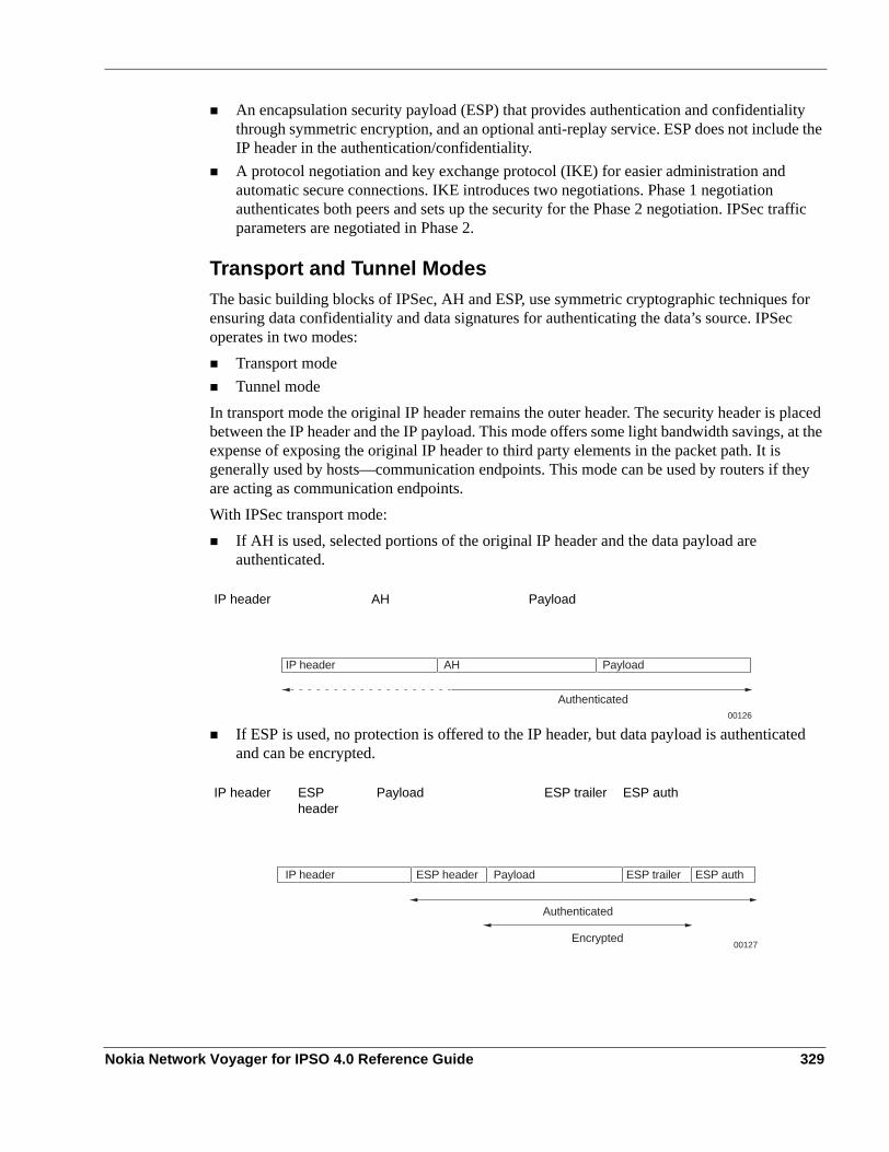
An encapsulation security payload (ESP) that provides authentication and confidentiality through symmetric encryption, and an optional anti-replay service. ESP does not include the IP header in the authentication/confidentiality.A protocol negotiation and key exchange protocol (IKE) for easier administration and automatic secure connections. IKE introduces two negotiations. Phase 1 negotiation authenticates both peers and sets up the security for the Phase 2 negotiation. IPSec traffic parameters are negotiated in Phase 2.
Transport and Tunnel ModesThe basic building blocks of IPSec, AH and ESP, use symmetric cryptographic techniques for ensuring data confidentiality and data signatures for authenticating the data’s source. IPSec operates in two modes:
Transport modeTunnel mode
In transport mode the original IP header remains the outer header. The security header is placed between the IP header and the IP payload. This mode offers some light bandwidth savings, at the expense of exposing the original IP header to third party elements in the packet path. It is generally used by hosts—communication endpoints. This mode can be used by routers if they are acting as communication endpoints.With IPSec transport mode:
If AH is used, selected portions of the original IP header and the data payload are authenticated.
If ESP is used, no protection is offered to the IP header, but data payload is authenticated and can be encrypted.
IP header AH Payload
IP header ESP header
Payload ESP trailer ESP auth
IP header AH
Authenticated
Payload
00126
IP header ESP header Payload ESP trailer ESP auth
Authenticated
Encrypted00127
Nokia Network Voyager for IPSO 4.0 Reference Guide 329

8
In tunnel mode, the original IP datagram is placed inside a new datagram, and AH or ESP are inserted between the IP header of the new packet and the original IP datagram. The new header points to the tunnel endpoint, and the original header points to the final destination of the datagram. Tunnel mode offers the advantage of complete protection of the encapsulated datagram and the possibility to use private or public address space. Tunnel mode is meant to be used by routers—gateways. Hosts can operate in tunnel mode too.With IPSec tunnel mode:
If AH is used, the outer header is authenticated as well as the tunneled packet:
If ESP is used, the protection is offered only to the tunneled packet, not to the new outer IP header. By default, ESP, providing the highest level of confidentiality, is used in this release.
Building VPN on ESPTunneling takes the original IP header and encapsulates it within ESP. Then it adds a new IP header, containing the address of a gateway, to the packet. Tunneling allows you to pass nonrouteable and private (RFC 1918) IP addresses through a public network that otherwise would not be accepted. Tunneling with ESP using encryption also has the advantage of hiding the original source and destination addresses from the users on the public network, reducing the chances of traffic analysis attacks. Tunneling with ESP can conceal the addresses of sensitive internal nodes, protecting them from attacks and hiding its existence to outside machines.
Protocol Negotiation and Key ManagementTo successfully use the IPSec protocol, two gateway systems must negotiate the algorithms used for authentication and encryption. The gateway systems must authenticate themselves and choose session keys that will secure the traffic. The exchange of this information leads to the creation of a security association (SA). An SA is a policy and set of keys used to protect a one-
New IP header AH Old IP header
Payload
New IP header ESP header Old IP header
Payload ESP trailer ESP auth
New IP header AH Old IP header
Authenticated
Payload
00128
New IP header ESP header Old IP header
Authenticated
Payload
00129
ESP trailer ESP auth
Encrypted
330 Nokia Network Voyager for IPSO 4.0 Reference Guide

way communication. To secure bidirectional communication between two hosts or two security gateways, two SAs (one in each direction) are required.Processing the IPSec traffic is largely a question of local implementation on the IPSec system and is not a standardization subject. However, some guidelines are defined to ensure interoperability between multivendor IPSec systems.“Security Architecture for IP”, RFC 240 defines a model with the following two databases:
The security policy database that contains the security rules and security services to offer to every IP packet going through a secure gatewayThe SA database that contains parameters associated with each active SA. Examples are the authentication algorithms, encryption algorithms, keys, lifetimes for each SA (by seconds and bytes), and modes to use.
To offer a secure and automated IPSec SA negotiation, IETF added a new protocol. The Internet Key Exchange, (IKE, RFC 2409), based on ISAKMP (RFC 2408), is a more extended framework for SA authentication and key exchange. IKE is implemented on top of UDP, port 500. IKE provides authenticated secure key exchange with perfect forward secrecy (based on the Diffie- Hellman protocol) and mutual peer authentication using public keys or shared secrets. The IKE protocol defines two phases:
Phase 1In order to safely set an IPSec SA, the two peers first establish a secure channel, which is an encrypted and authenticated connection. The two peers agree on authentication and encryption methods, exchange keys, and verify each other’s identities. The secure channel is called ISAKMP Security Association. Unlike IPSec SAs, ISAKMP SAs are bi-directional and the same keys and algorithms protect inbound and outbound communications. IKE parameters are negotiated as a unit and are termed a protection suite. Mandatory IKE parameters are:
a. Symmetric Encryption algorithmb. Hash functionc. Authentication method: pre-shared key and X.509 certificates. See the following section
on “Using PKI”.d. Group for Diffie-Hellman
Other optional parameters such as SA lifetime can also be part of the protection suite.Phase 2
IPSec SAs are negotiated once the secure ISAKMP channel is established. Every packet exchanged in phase 2 is authenticated and encrypted according to keys and algorithms selected in the previous phase.The one method to complete phase 1 is Main Mode.The Main Mode negotiation uses six messages, in a three two-way exchange. The messages containing the identity information are not authenticated nor encrypted.One mode is defined for phase 2. This mode is called Quick Mode. Quick Mode uses three messages, two for proposal parameters and a third one to acquit the choice. With “perfect forward secrecy” enabled, the default value in Nokia’s configuration, a new Diffie-Hellman
Nokia Network Voyager for IPSO 4.0 Reference Guide 331

8
exchange must take place during Quick Mode. Consequently, the two peers generate a new Diffie-Hellman key pair.
Using PKIFor Phase 1 negotiation of IKE, the IPSec systems can use X.509 certificates for authentication. X.509 certificates are issued by Certificate Authorities (CA). IPSO IPSec implementation supports Entrust VPN connector and Verisign IPSec on site services. Contact any of the listed CA vendors for certificate signing services.To use the X.509 certificates, the IPSec system should follow these steps:1. Install the trusted CA certificates (all, including yours) of all the peer IPSec systems.2. Make a certificate request with all the information required to identify the system such as
your IP address, a fully qualified domain name, organization, organization unit, city, state, country, and contact email address.
3. Forward the certificate request to the CA or corresponding RA (Registration Authority) using the Web interface or another file transfer mechanism.CA or RA verifies the identity of the IPSec system and generates the approved certificate. A certificate is valid only for a certain period of time.
4. Download and install the approved device certificate and the CA certificate on the IPSec system.
5. Link the certificate to an IPSec policy.
NoteThe IPSO Web-based Network Voyager interface provides the mechanism you need to complete all the above steps.
IPSec Implementation in IPSO
NoteThe IP2250 appliance does not support IPSO’s implementation of IPSec.
The IPSO operating system provides a native IPSec implementation supporting ESP in tunnel mode. This implementation is compliant with the following RFCs:
Table 20 IPSec RFCs
RFC Description
RFC 2401 Security Architecture for the Internet Protocol
RFC 2402 IP authentication header
332 Nokia Network Voyager for IPSO 4.0 Reference Guide

The IPSec configuration in Network Voyager is based on three IPSec objects: proposals, filters, and policies.
Proposals—Define the combination of encryption and authentication algorithms that secure phase 1 negotiation (Main Mode) as well as phase 2 negotiations (Quick Mode) and IPSec packets.Filters—Determine which packets relate to certain proposals. The filters are matched against the source or destination fields in the packet header depending on whether the filters are used as source or destination filters. If applicable, Protocol and Port fields are also used. Policies—Link the type of IPSec security that proposals with traffic define. The traffic is defined by a list of filters specified for the source address and a second list specified for the destination address. If the source address of a packet matches a filter from the source filter list and the destination address matches a filter from the destination filter list, IPSec is applied to the traffic. Protocols and ports are used in the matching process, if applicable.The kind of security applied to a defined traffic is specified by a list of proposals ordered by priority. This list is offered to the other peer beginning with the lowest priority value proposal.Proposals and filters can be reused in different policies. Other elements defined in a policy are authentications methods (Preshared Keys or X.509 Certificates) and lifetime attributes.
Miscellaneous Tunnel RequirementsIPSec tunnels are defined by local and remote tunnel addresses. The tunnel requires a policy to define what traffic is encapsulated by the tunnel and what security to use in the encapsulation. The traffic that matches filters associated to the policy is encapsulated by using tunnel addresses. Policies can also be reused in different tunnels. An IPSec tunnel cannot function without an associated policy.
RFC 2406 IP Encapsulating Security Payload (ESP)Supports algorithms: 3DES, DES, and Blowfish for encryption and SHA-1 and MD5 for authentication.
RFC 2407 The Internet IP Security Domain of Interpretation for ISAKMP
RFC 2408 Internet Security Association and Key Management Protocol (ISAKMP)
RFC 2409 The Internet Key Exchange (IKE)
RFC 2411 IP Security Document Roadmap
RFC 2412 The OAKLEY Key Determination Protocol
RFC 2451 ESP CBC-Mode Cipher Algorithms
Table 20 IPSec RFCs
RFC Description
Nokia Network Voyager for IPSO 4.0 Reference Guide 333

8
NoteNative IPSO IPSec tunnels cannot coexist in the same machine with Check Point IPSec software. Before you use IPSO IPSec software, ensure that no Check Point software is running. Likewise, before you use Check Point IPSec software, ensure that no IPSO IPSec software is running.
You can create IPSec tunnel rules with or without a logical interface for all IPSO platforms except the IP3000 series. For the IP3000 series platform, you must create a logical interface with each tunnel rule. You can create tunnel rules without logical interfaces if you require a large number of tunnels. However, creating IPSec tunnels without interfaces can slow down non-IPSec traffic.
Phase 1 ConfigurationFor IPSO, the Phase 1 encryption and authentication algorithms are the same as those used in Phase 2. However, if Phase 2 encryption is NULL, such as with an AH proposal or NULL-encryption-ESP proposal, IPSO uses 3DES as Phase 1 for the encryption algorithm.The values set in the Lifetime table are used as the hard lifetime of the Phase 2 SA. Phase 1 lifetimes are calculated as Hard Phase 1 lifetime (seconds) = 5* Hard Phase 2 lifetime (seconds). The soft limit value is approximately 80-90 percent of the hard-limit value, depending on whether the device is working as a session initiator or responder.If you create tunnels between an IPSO platform and non-IPSO systems, configure the non-IPSO system so that the Phase 1 lifetime is five times the Phase 2 lifetime. Set the encryption to 3DES, and set the authentication so that it is the same as the Phase 2 algorithm.
Platform SupportIPSec is supported across all Nokia security appliances.
IPSec ParametersThe two IPSec peers should agree on authentication and encryption methods, exchange keys, and be able to verify each other’s identities. While you configuring the peer IPSec devices, consider the following:
At least one proposal (encryption algorithm and hash function) should match on the peer devices. See “Proposal and Filters” in “Creating an IPSec Policy” for more information.Authentication method:
If you are using Shared Secret, both devices should have the same shared secret. See “Putting It All Together” in “Creating an IPSec Policy” for more information.If you are using X.509 certificates, both devices should install all the trusted CA certificates in the trust hierarchy. See “Trusted CA Certificates” in “Creating an IPSec Policy” for more information.
334 Nokia Network Voyager for IPSO 4.0 Reference Guide

Some IPSec systems require that the SA lifetimes (seconds, as well as megabytes) match on both devices. See “Putting It All Together” in “Creating an IPSec Policy” for more information.IKE and PFS groups should match on both devices. See “Putting It All Together” in “Creating an IPSec Policy” for more information.The Diffie-Hellman key exchange uses the IKE group during the establishment of Phase 1 ISAKMP SA. Value options are 1, 2, or 5; 2 is the default value.The Diffie-Hellman key exchange uses the PFS group in Phase 2 to construct key material for IPSec SAs. The value options are 1, 2, 5, or none; 2 is the default. Setting the value to none disables PFS.
NoteWhen IPSO is acting as the responder of the Phase 2 negotiation, it always accepts the PFS group proposed by the initiator.
Creating an IPSec Policy
Choosing IPv4 or IPv6 General Configuration Page
To chose IPv4 or IPv6 general configuration pages1. Click IPSec under Security and Access in the tree view. .2. Access the appropriate IPSec General Configuration page:
To display the IPv4 IPSec General Configuration page—click on the IPSec linkTo display the IPv6 IPSec General Configuration page—first click on the IPv6 Configuration link; this takes you to the main IPv6 page. Next, click on the IPSec link; this takes you to the IPv6 IPSec General Configuration Page.If you are on the IPv4 General Configuration page—6to move to the IPv6 General configuration page, scroll down to the bottom of the page and click the IPv6 IPSec General Configuration link.
NoteApplication procedures are the same for both configuration page types. The primary difference is the format of the IP addresses. IPv4 uses dotted quad format and IPv6 uses canonical address format. Selected range values might be different; consult the inline Help option for specifics.
The following sections describe how to create an IPSec policy.
Nokia Network Voyager for IPSO 4.0 Reference Guide 335

8
Proposal and Filters1. Under the Proposals table, enter a name for a new proposal in the New Proposal text box.
Click either ESP or AH.
NoteIf you click AH, the Encryption Alg (algorithm) must always be set to NONE. If this is not done, an error message appears when you click Apply.
2. From the drop-down list in the Authentication Alg and Encryption Alg fields, select the necessary algorithms. Click Apply.
3. Under the Filters table, enter a new filter name in the New Filter text box for the subnetwork that you want to control.
4. Enter the subnet address and the mask length in the Address and Mask Length text boxes.
NoteDestination filters across multiple rules (tunnel or transport) should not overlap, although source filters can overlap.
5. Click Apply.The new filter information is added to the Filters list. If needed, you can then define a protocol or a port. Defaults are assumed. Repeat this operation for as many networks you need.
NoteEach Network Voyager page displays a maximum of 10 proposals or 10 filters. If you create more than 10, they are continued on new pages. Access these pages by clicking the link directly below the appropriate section. The link to more pages appears only after you create more than 10 proposals or filters.
Skip to “Putting It All Together” if you do not plan to use a X.509 certificate and want to use shared secret for authentication.
Trusted CA CertificatesTrusted CA certificates are the publicly available certificates of the CAs.
To select a trusted CA certificate1. Under the Trusted CA Certificates table, enter a name in the New CA text box. Click Apply.2. An Apply Successful message appears and the name of the CA you just entered appears in
the Trusted CA Certificates table.
336 Nokia Network Voyager for IPSO 4.0 Reference Guide

3. Click on the new link with the same name that you entered in Step 1. This action takes you to the IPSec Certificate Addition page for that specific certificate.
4. On the Certificate Addition page, you have two choices:If you have the PEM (base64) encoded certificate, select the Paste the PEM Certificate option.If you know the URL to the certificate (including the local file), select the Enter URL to the Certificate option.
5. Click Apply.
NoteThis action takes you to the next page that asks for the PEM encoded certificate or the URL information of the certificate. If you have the PEM encoded certificate, proceed to step 5; if you reach the URL to the certificate, skip to step 6.
6. If you are asked to enter the PEM coded certificate, use the copy and paste function of your browser to copy the PEM text of the certificate into the text box titled Paste the PEM Encoded Certificate; click Apply. This action should print a Success message. Click on the link titled IPSec General Configuration page to return to the main IPSec configuration page.
7. If you are asked to enter URL information of the certificate, enter the URL to the certificate. Examples are:
http://test.acme.com/dev1.certftp://test.acme.com/dev1.certfile://tmp/dev1.cert1dap://test.acme.com/cn=dev1.acme.com?pem_x509?sub
Enter the HTTP realm information (only for the HTTP protocol); enter the user name and password if needed to connect to the FTP/HTTP server.
8. Click Apply. This action should print a Success message. Click on the link titled IPSec General Configuration page to return to the main IPSec Configuration page.Repeat the steps in this procedure for every trusted CA certificate that needs to be installed.
NoteOn successful completion, a green button appears under the Certificate File column. The green button indicates that the certificate file is present on the machine and it is also a link to view the installed certificate.
Device CertificatesA device certificate is used to identify a particular IPSec system. Follow the steps below.
Nokia Network Voyager for IPSO 4.0 Reference Guide 337

8
To enroll and install a device certificate1. Under the Device Certificates table, enter a name in the New Certificate text box, then click
Apply.2. An Apply Successful message appears and the name of the CA you just entered appears in
the Device Certificates table.3. Click on the new link with the same name that you entered in step 1.
This action takes you to the IPSec Certificate Enrollment page for that named item.4. Enter all the fields on the page that identifies the IPSec system and click Apply.
This action should take you to the page where a PEM-encoded certificate request is shown.
NoteRemember the passphrase that you entered for future reference.
5. Click on Save to avoid the risk of losing your private key.6. If you have access to the CA/RA enrollment page, open the page in a separate browser
window.Use the copy and paste function or your browser to paste the PEM certificate request into the CA/RA certificate enrollment page.
NoteSome CAs do not expect the header (----BEGIN CERTIFICATE REQUEST----) and the footer (----END CERTIFICATE REQUEST----) lines in the text.
Alternatively, you can copy the text in a file and send the file to the CA/RA by FTP or some other file transfer mechanism that is supported. Contact the CA for details.
7. If you could successfully make the certificate request select Completed the certificate request at the CA site option; otherwise, select the Will do it later option.
8. Click Apply.If you chose Completed the certificate request at the CA site, proceed to step 8. If you chose the Will do it later option, skip to step 10.
9. If you chose the Completed the request at the CA site, a new link Click here to install the Certificate appears towards the bottom of the page. To install the certificate, click the link to go to the page described in steps 3–6 under “Trusted CA Certificates.”
NoteBefore you install the certificate, ensure that CA approved the certificate and that you know how to access the approved certificate. If you need to wait for the CA’s approval,
338 Nokia Network Voyager for IPSO 4.0 Reference Guide

you can click on the link with the Certificate name in the IPSec General Configuration page to install the certificate.
10. If you chose Will do it later to make the certificate request, the link on the main IPSec General Configuration still points to the certificate request page. You can repeat steps 5 through 8 to install the certificate.
11. If you finished all the steps, two green buttons appear. You can click on the button under the Certificate column to view the certificate.
Advanced IPSecThe following options are available through the IPSec Advanced Configuration page; the link is at the bottom of the IPSec General Configuration Page:
Log Level—IPSO IPSec provides three levels of message logging through the syslog subsystem:
Error (default value)—only error messages or audit messages are logged.Info—provides minimum information about the successful connections to the system. Also includes error messages.Debug—besides the informational messages, gives full details of the negotiations that the subsystem performs.
NoteIn any of the log level options, confidential information (such as secrets or session keys) are not shown.
Allowing tunnels without logical interfacesThis option allows for the creation of IPSec tunnels that are not associated with a logical tunnel interface. You can create tunnels without logical interfaces if you want a greater number of tunnels and to achieve scalability. The Create a logical interface field appears only if the Allow tunnels without logical interface field is selected to On in the Advanced Configuration page.
NoteEnabling this option might slow down forwarding of non-IPSec packets.
LDAP serversIPSO IPSec implementation supports automatic CRL retrieval following the LDAPv2/3 protocol specification (RFC 2251). To retrieve CRL automatically from the centralized directory enter the URL of the directory server.Because of different implementations, the internal configuration of the directory server might not be compatible with IPSO that has implemented LDAP query formats.
Nokia Network Voyager for IPSO 4.0 Reference Guide 339

8
Putting It All Together
To complete creating an IPSec policy1. Under the Policies table, enter a name for a new policy in the New Policy text box, then
click Apply.An Apply Successful message appears and the policy name appears in the Policies table.
2. Click on the policy name in the Policies table.The IPSec Policy Configuration page for the name appears.
3. Under the Linked Proposals table, from the drop-down list in the Add a Proposal field, select the name of the proposal to use in this policy. Assign a priority in the Priority text box, then click Apply.Repeat this step for every proposal that must be offered to the other peer. The proposals are offered starting with the lowest priority value (one).
4. Select the authentication method (Pre-Shared Secrets or X.509 Certificates) needed in this policy, then click Apply.
NoteOnly one method can be active at a time.
5. If you chose Pre-Shared Secret, enter the shared secret in the Enter Shared Secret text box. Enter the secret again, in the Shared Secret (Verify) text box, for verification.
6. Click Apply. If the secret has been entered correctly the red light of the Secret Status field turns green after you click Apply.
7. If you chose X.509 Certificates, select the certificate name from the list of device certificates that identifies this machine.
8. In the Lifetime table, if the default lifetime values are not appropriate, modify them in the Seconds and Megabytes text boxes.
NoteLifetimes must be set to the same value between peers when negotiation is initiated. If they are not set the same, IPSO IPSec might deny the negotiation.
9. In the Diffie-Hellman Groups table, if the default values in the IKE Group and PFS Group text boxes are not appropriate, modify them, then click Apply.
NoteEach Network Voyager page displays a maximum of 10 policies. If you create more than 10 policies, they are continued on new pages. Access these pages by clicking the link directly
340 Nokia Network Voyager for IPSO 4.0 Reference Guide

below the policy section. The link to more pages appears only after you create more than 10 policies.
Creating an IPSec Tunnel Rule
To create an IPSec tunnel rule1. Click IPSec under Configuration > Security and Access in the tree view.2. Click the IPSec link.3. Under the IPSec Tunnel Rules heading, enter a name in the New Tunnel text box.4. If the Create a logical interface option appears and you want to create a logical interface, set
the button to Yes.5. Enter the IP address of the local end of the IPSec tunnel in the Local Address text box.
The local address must be one of the system interface addresses and must be the remote endpoint configured for the IPSec tunnel at the remote gateway.
6. Enter the IP address of the remote interface to which the IPSec tunnel is bound in the Remote Address text box.The remote endpoint cannot be one of the system interface addresses and must be the local endpoint configured for the IPSec tunnel at the remote gateway.
7. Click Apply.An Apply Successful message appears and an entry for the new tunnel appears in the IPSec Tunnel Rules table.
NoteIPSO can support up to 1500 rules. However, each Network Voyager page displays a maximum of 10. If you create more than 10 rules, they are continued on new pages. Access these pages by clicking the link directly below the rule section. The link to more pages appears only after you create more than 10 rules.
8. Click on the new link with the name that you entered in the IPSec Tunnel Rules table. The IPSec Tunnel page appears.
9. (Optional) Activate Hello Protocol inside the tunnel, then click Apply.
NoteThis and the following two steps are not applicable for tunnels without logical interface parameters.
Nokia Network Voyager for IPSO 4.0 Reference Guide 341

8
The hello protocol determines the connectivity of an end-to-end logical tunnel. As a result, the hello protocol modifies the link status of the logical interface. If the connectivity of an unavailable tunnel is restored, the hello protocol brings up the link.
10. (Optional) If the hello protocol is active, enter a value for the Hello Interval and Dead Interval text boxes, then click Apply.The Hello Interval text box specifies the interval (number of seconds) between the Hello packets being sent through the tunnel. The Dead Interval text box determines the interval (number of seconds) in which you do not receive an Hello packet before the link status changes to unavailable.
11. (Optional) Change the logical name of the interface to a more meaningful one by entering the preferred name in the Logical Name text box, then click Apply.
12. From the drop-down list in the Select Policy field, select the policy name that is needed, then click Apply.This action displays a new table, Linked Policy.
13. From the drop-down list in the Source Filters column, select a filter name that corresponds to the source of the traffic that this policy will protect, then click Apply.Repeat this operation to add as many filters as necessary. Click Apply after each selection.
NoteIf there are 40 or more source or destination filters, they do not appear as a list on the Network Voyager page. To view a filter that is not displayed, type the name of the filter in the appropriate field.
14. From the drop-down list in the Destination Filters column, select a filter name that corresponds to the destination of the traffic that will be protected by this policy. Click Apply.Repeat this operation to add as many filters as necessary. Click Apply after each selection.
15. ((Optional) In the Options table, select the option Include End-Points in the Filters, then click Apply.
16. Click Save to make your changes permanent.
Transport Rule
To create a transport rule1. Click IPSec under Configuration > Security and Access in the tree view.2. Click the IPSec Transport Rules Configuration link at the bottom of the page.
The IPSec Transport Rules page appears. The structure of this page is common to both IPv4 and IPv6.
3. Enter the name of the new rule in the New Transport Rule field. In the Select a policy field select the desired option from the drop-down list, the click Apply.
342 Nokia Network Voyager for IPSO 4.0 Reference Guide

The new entry appears in the IPSec Transport Rules table.4. (Optional) To change the policy entry without changing the name of the associated transport
rule, perform the following steps:a. Click in the blank square next to the current policy entry. Click Apply. The policy name
is removed.b. Under the Policy column, select a policy option from the drop-down list and click Apply.
The new policy is entered without changing the associated transport rule.5. From the drop-down list in the Source Filters column, select a filter name that corresponds
to the source of the traffic that will be protected by this policy. Click Apply.Repeat this operation to add as many filters as necessary.
6. Click Apply after each selection.
NoteSelect as source filters only filters that present a single host but no subnet.
NoteIf you have 40 or more source or destination filters, they are not displayed as a list on the Network Voyager page. To view a filter that is not displayed, type the name of the filter in the appropriate field.
7. From the drop-down list in the Destination Filters column, select a filter name that corresponds to the destination of the traffic to be protected by this policy.
8. Click Apply and then click Save to make your changes permanent.9. To delete any entries, check the Delete check box and click Apply.
Click Save to make delete permanent.
NoteEach Network Voyager page displays a maximum of 10 transport rules. If you create more than 10 rules, they are continued on new pages. Access the new pages by clicking the link directly below the rule section. The link to more pages appears only after you create more than 10 transport rules.
Nokia Network Voyager for IPSO 4.0 Reference Guide 343

8
IPSec Tunnel Rule ExampleThe following steps tell how to configure a sample IPSec tunnel. The following figure below shows the network configuration for this example.
To configure Nokia Platform 11. Click IPSec under Configuration > Security and Access in the tree view.2. Under the Proposals table, enter md5-des as a name for a new proposal in the New Proposal
text box.3. In the Type field, select the ESP button.4. Select MD5 from the Authentication Alg drop-down list and DES from the Encryption Alg
drop-down list. Click Apply.5. In the Filters table, enter site_A as a new filter name in the New Filter text box. Enter
192.68.22.0 in the Address text box and 24 in the Mask Length text box. Click Apply.The new entry appears in the Filters table.
6. In the Filters table, enter site_B as a new filter name in the New Filter text box. Enter 192.68.23.0 in the Address text box and 24 in the Mask Length text box. Click Apply.
NoteIn this example, the authentication method is a preshared secret, so you don’t need to select a certificate.
7. (Optional) Click the IPSec Advanced Configuration link.
Nokia Platform 1 Nokia Platform 2192.68.22.0/24 192.68.23.0/24
192.68.26.74/30192.68.26.65/30
00040
Internet
IPsec Tunnel
Remote PCsSite A
Remote PCsSite B
344 Nokia Network Voyager for IPSO 4.0 Reference Guide

8. (Optional) From the drop-down list in the Log Level field, select Info. Click Apply.9. (Optional) Click Up.10. In the Policies table, enter rule_1 as the name for a new policy in the New Policy text box.
Click Apply.11. In the policies table, click on rule_1.
The corresponding Configuring Policy page appears to complete the missing parameters of the policy.
12. Select MD5-DES from the Add a Proposal drop-down list. Enter 1 in the Priority text box.13. If no default is selected, select Pre-Shared Secret in the Authentication Method field.14. Enter a text string, such as secret, in the Enter Shared Secret text box and Shared Secret
(Verify) text box. Click Apply.15. Click Up to return to the IPSec General Configuration page.
Under the IPSec Tunnel Rules table, enter IPSec_tunn in the New Tunnel field.16. If Create a logical interface appears, select Yes.17. Enter 192.68.26.65 in the Local Address text box.18. Enter 192.68.26.74 in the Remote Address text box.
Click Apply.19. Click on the name in Tunnel Rules table.
The IPSec Tunnel IPSec_tunn page appears.20. (Optional) Click On to activate Hello Protocol.
Click Apply. The Hello Interval and Dead Interval text boxes appear.21. (Optional) Enter 60 as a value in the Hello Interval text box and enter 180 as a value for the
Dead Interval text box. Click Apply.
22. From the drop-down list in the Select Policy field, select rule_1. Click Apply.A new table, Linked Policy, appears.
23. Select SITE_A from the Source Filters drop-down list.24. Select site_B from the Destination Filters drop-down list.25. Click Apply.26. Click Save to make your changes permanent.
Nokia Network Voyager for IPSO 4.0 Reference Guide 345

8
Configure Nokia Platform 2Now set up network application platform 2 (Nokia Platform 2). Perform the same steps that you performed to configure Nokia Platform 1, with the following changes.1. Step 18; enter 192.68.26.74 in the Local Address text box.2. Step 19; enter 192.68.26.65 in the Remote Address text box.3. Step 24; select SITE_B from the Source Filters drop-down list.4. Step 25; select SITE_A from the Destination Filters drop-down list.
IPSec Transport Rule ExampleThe following procedure tells you how to configure a sample IPSec authentication connection. The following figure shows the network configuration for this example.
To configure Nokia Platform 1 (IPSO)1. Click IPSec under Configuration > Security and Access in the tree view of the network
application platform 1 (Nokia Platform 1, IPSO).2. Under the Proposals table, enter ah-md5 as a name for a new proposal in the New Proposal
text box.3. In the Type field, click AH.4. Select MD5 from the Authentication Alg drop-down list and None from the Encryption Alg
drop-down list. Click Apply.
5. In the Filters table, enter local as a new filter name in the New Filter text box. Enter 192.68.26.65 in the Address text box and 32 in the Mask Length text box. Click Apply.The new entry appears in the Filters table.
6. In the Filters table, enter remote as a new filter name in the New Filter text box. Enter 192.68.26.74 in the Address text box and 32 in the Mask Length text box. Click Apply.
Internet
Nokia Platform 1(IPSO)
PC 1
192.68.26.74/30eth-s1p3c0192.68.26.65/30
00130
346 Nokia Network Voyager for IPSO 4.0 Reference Guide

NoteIn this example, the authentication method is a preshared secret, so you do not need to select a certificate.
7. (Optional) Click the IPSec Advanced Configuration link.8. (Optional) From the drop-down list in the Log Level field, select Info.
Click Apply.9. (Optional) Click Up.10. In the Policies table, enter rule_2 as the name for a new policy in the New Policy text box.
Click Apply.11. In the policies table, click on rule_2.
The corresponding Configuring Policy page appears to complete the missing parameters of the policy.
12. Select AH-MD5 from the Add a Proposal drop-down list. Enter 1 in the Priority text box.
13. If no default is selected, select Pre-Shared Secret in the Authentication Method field.14. Enter secreted in the Enter Shared Secret text box and Shared Secret (Verify) text box.
Click Apply.15. Click Up to return to the IPSec General Configuration page.16. Select IPSec Transport Rules Configuration link.
The IPSec Transport Rules page appears.17. In the New Transport Rule text box under the IPSec Transport Rules table, enter
IPSec_trans.18. In the Select a policy text box, select rule_2.19. Select Apply.
The new transport rule appears in the IPSec Transport Rules table.20. Select local from the Source Filters drop-down list.21. Select remote from the Destination Filters drop-down list.22. Click Apply.23. Click Save to make your changes permanent.
Nokia Network Voyager for IPSO 4.0 Reference Guide 347

8
Configure PC1You now need to set up PC1. Perform the same steps that you performed to configure Nokia Platform 1 (IPSO), with the following changes.1. Step 6; for the local filter, enter 192.68.26.74 in the Address text box.2. Step 7; for the remote filter, enter 192.68.26.65 in the Address text box.
Changing the Local/Remote Address or Local/Remote Endpoint of an IPSec Tunnel
1. Click IPSec under Configuration > Security and Access in the tree view.2. In the Name column, click the name link for which you want to change the IP address.
Example: tun0c13. You are taken to the IPSec Tunnel page.4. (Optional) Enter the IP address of the local end of the IPSec tunnel in the Local Address text
box.The local address must be one of the system’s interfaces and must be the same as the remote address configured for the IPSec tunnel at the remote router.
5. (Optional) Enter the IP address of the remote end of the IPSec tunnel in the Remote Address text box.The remote address cannot be one of the system’s interfaces and must be the same as the local address configured for the IPSec tunnel at the remote router.
6. Click Apply.7. To make your changes permanent, click Save.
Removing an IPSec Tunnel
To remove an IPSec tunnel1. Click IPSec under Security and Access in the tree view.
The IPv4 IPSec General Configuration page appears by default. If the IPv6 General Configuration page is desired, scroll to the bottom of the page and click on the IPv6 IPSec General Configuration link.
2. Under the IPSec Tunnel Rules heading, click in the Delete square of the tunnel name(s) you wish to delete.
3. Click Apply.An Apply Successful message appears and the tunnel(s) selected for deletion are removed from the IPSec Tunnel Rules table.
4. To make your changes permanent, click Save.
348 Nokia Network Voyager for IPSO 4.0 Reference Guide

Miscellaneous Security SettingsThe Miscellaneous Security Settings page under Configuration > Security and Access allows you to change the handling of TCP packets. The default behavior is for IPSO to drop TCP packets that have both SYN and FIN bits set. This behaviour addresses a CERT advisory. For more information on that advisory, go to http://www.kb.cert.org/vul/id/464133. You must change the default configuration if you want your Nokia platform to accept packets that have both the SYN and FIN bits set. Complete the following procedure to configure your platform to accept packets that have both SYN and FIN bits set.
To set TCP flag combinations1. Click Miscellaneous Security Settings under Configuration > Security and Access in the tree
view.2. Select On next to Allow TCP/IP(rfc1644) mode (SYN-FIN together).
Select Off to return to the default configuration if you have enabled your platform to accept packets that have both SYN and FIN bits set..
3. Click Apply4. Click Save to make your change permanent
Nokia Network Voyager for IPSO 4.0 Reference Guide 349

8
350 Nokia Network Voyager for IPSO 4.0 Reference Guide

9 Configuring Routing
This chapter describes the IPSO routing subsystem, how to configure the various routing protocols that are supported, route aggregation, and route redistribution.
Routing OverviewThe Nokia routing subsystem, Ipsilon Scalable Routing Daemon (IPSRD), is an essential part of your firewall. IPSRD’s role is to dynamically compute paths or routes to remote networks. Routes are calculated by a routing protocol. IPSRD provides routing protocols, allows routes to be converted or redistributed between routing protocols, and, when there are multiple protocols with a route to a given destination, allows you to specify a ranking of protocols. Based on the ranking, a single route is installed in the forwarding table for each destination.You can monitor routing by following links from Network Voyager. Another monitoring tool is ICLID, which provides interactive, text-based monitoring of the routing subsystem.
Routing ProtocolsRouting protocols compute the best route to each destination. Routing protocols also exchange information with adjacent firewalls. The best route is determined by the cost or metric values.Routing protocols can be broken up into two major categories: exterior gateway protocols (EGPs) and interior gateway protocols (IGPs). Interior gateway protocols exchange routing information inside an autonomous system (AS). An AS is a routing domain, such as inside an organization, that contacts its own routing. An EGP exchanges routing information between ASes and provides for specialized policy-bound filtering and configuration.IPSRD supports three interior gateway protocols: RIP (Routing Information Protocol), IGRP (Interior Gateway Routing Protocol), and OSPF (Open Shortest Path First).Static routes and aggregate routes are also supported. For more information on static routes, see “Static Routes” on page 394. For more information on aggregate routes, see “Route Aggregation” on page 398.
Nokia Network Voyager for IPSO 4.0 Reference Guide 351

9
RIPRIP is a commonly used IGP. RIP version 1 is described in RFC 1058, and RIP version 2 is described in RFC 1723. IPSRD supports these version, as well as RIPng, which supports IPv6 interfaces. RIP uses a simple distance vector algorithm called Bellman Ford to calculate routes. In RIP, each destination has a cost or metric value, which is based solely on the number of hops between the calculating firewall and the given destination.The maximum metric value is 15 hops, which means that RIP is not suited to networks within a diameter greater than 15 firewalls. The advantage of RIP version 2 over RIP version 1 is that it supports non-classful routes. Classful routes are old-style class A, B, C routes. You should use RIP version 2 instead of RIP version 1 whenever possible.
IGRPIGRP (Interior Gateway Routing Protocol) is a distance vector protocol. IGRP has a number of metrics for each destination. These metrics include link delay, bandwidth, reliability, load, MTU, and hop count. A single composite metric is formed by combining metrics with a particular weight.Like RIP version 1, IGRP does not fully support non-classful routing.
OSPFOSPF (Open Shortest Path First) is a modern link-state routing protocol. It is described in RFC 2328. It fully supports non-classful networks. OSPF has a single, 24-bit metric for each destination. You can configure this metric to any desired value.OSPF allows the AS to be broken up into areas. Areas allow you to increase overall network stability and scalability. At area boundaries, routes can be aggregated to reduce the number of routes each firewall in the AS must know about. If there are multiple paths to a single destination with the same computed metric, OSPF can install them into the forwarding table.
DVMRPDVMRP (Distance Vector Multicast Routing Protocol) is a multicast routing protocol (RIP, OSPF, and IGRP are unicast routing protocols). Multicasting is typically used for real-time audio and video when there is a single source of data and multiple receivers. DVMRP uses a hop-based metric and, like RIP, a distance-vector route calculation.
BGPBGP (Border Gateway Protocol) is an exterior gateway protocol that is used to exchange network reachability information between BGP-speaking systems running in each AS. BGP is unlike interior gateway protocols (IGRP or OSPF), which periodically flood an intra-domain network with all the known routing table entries and build their own reliability. Instead, BGP uses TCP as its underlying transport mechanism and sends update only when necessary.
352 Nokia Network Voyager for IPSO 4.0 Reference Guide

BGP is also a path-vector routing protocol, which limits the distribution of a firewall’s reachability information to its peer or neighbor firewalls. BGP uses path attributes to provide more information about each route. BGP maintains an AS path, which includes the number of each AS that the route has transited. Path attributes may also be used to distinguish between groups of routes to determine administrative preferences. This allows greater flexibility in determining route preference and achieves a variety of administrative ends.BGP supports two basic types of sessions between neighbors: internal (IBGP) and external (EBGP). Internal sessions run between firewalls in the same autonomous systems, while external sessions run between firewalls in different autonomous systems.
Route Maps
Route maps are used to control which routes are accepted and announced by dynamic routing protocols. Use route maps to configure inbound route filters, outbound route filters and to redistribute routes from one protocol to another.
You can define route maps only using the CLI, this feature is not available in Network Voyager. For information on route map commands, see the CLI Reference Guide.
Route maps support both IPv4 and IPv6 protocols, including RIP, BGP, RIPng, OSPFv2, and OSPFv3. BGP-4++ policy can only be specified using route maps. For the other protocols, you can use either route maps or the Route Redistribution and Inbound Route Filters features that you configure using Network Voyager. Route map for import policy corresponds to Inbound Route Filters; route map for export policy corresponds to Route Redistribution.
NoteRoute maps offer more configuration options than the Network Voyager configuration for route redistribution and inbound route filters. They are not functionally equivalent.
Protocols can use route maps for redistribution and Network Voyager settings for inbound route filtering and vice versa. However, if one or more route maps are assigned to a protocol (for import or export) any corresponding Network Voyager configuration (for route redistribution or inbound route filters) is ignored.
OSPFOpen Shortest Path First (OSPF) is an interior gateway protocol (IGP) used to exchange routing information between routers within a single autonomous system (AS). OSPF calculates the best path based on true costs using a metric assigned by a network administrator. RIP, the oldest IGP protocol chooses the least-cost path based on hop count. OSPF is more efficient than RIP, has a quicker convergence, and provides equal-cost multipath routing where packets to a single destination can be sent using more than one interface. OSPF is suitable for complex networks with a large number of routers. It can coexist with RIP on a network.
Nokia Network Voyager for IPSO 4.0 Reference Guide 353

9
IPSO supports OSPFv2, which supports IPv4 addressing, and OSPFv3, which supports IPv6 addressing.
Types of AreasRouters using OSPF send packets called Link State Advertisements (LSA) to all routers in an area. Areas are smaller groups within the AS that you can design to limit the flooding of an LSA to all routers. LSAs do not leave the area from which they originated, thus increasing efficiency and saving network bandwidth. You must specify at least one area in your OSPF network—the backbone area, which has the responsibility to propagate information between areas. The backbone area has the identifier 0.0.0.0. You can designate other areas, depending on your network design, of the following types:
Normal Area—Allows all LSAs to pass through. The backbone is always a normal area.Stub Area—Stub areas do not allow Type 5 LSAs to be propagated into or throughout the area and instead depends on default routing to external destinations. You can configure an area as a stub to reduce the number of entries in the routing table (routes external to the OSPF domain are not added to the routing table).NSSA (Not So Stubby Area)—Allows the import of external routes in a limited fashion using Type-7 LSAs. NSSA border routers translate selected Type 7 LSAs into Type 5 LSAs which can then be flooded to all Type-5 capable areas. Configure an area as an NSSA if you want to reduce the size of the routing table, but still want to allow routes that are redistributed to OSPF.
It is generally recommended that you limit OSPF areas to about 50 routers based on the limitations of OSPF (traffic overhead, table size, convergence, and so on). All OSPF areas must be connected to the backbone area. If you have an area that is not connected to the backbone area, you can connect it by configuring a virtual link, enabling the backbone area to appear contiguous despite the physical reality.
NoteIf you need to connect two networks that both already have backbone areas and you do not want to reconfigure one to something other than 0.0.0.0, you can connect the two backbone areas using a virtual link.
Each router records information about its interfaces when it initializes and builds an LSA packet. The LSA contains a list of all recently seen routers and their costs. The LSA is forwarded only within the area it originated in and is flooded to all other routers in the area. The information is stored in the link-state database, which is identical on all routers in the AS.
354 Nokia Network Voyager for IPSO 4.0 Reference Guide

Area Border RoutersRouters called Area Border Routers (ABR) have interfaces to multiple areas. ABRs compact the topological information for an area and transmit it to the backbone area. Nokia supports the implementation of ABR behavior as outlined in the Internet draft of the Internet Engineering Task Force (IETF). The definition of an ABR in the OSPF specification as outlined in RFC 2026 does not require a router with multiple attached areas to have a backbone connection. However, under this definition, any traffic destined for areas that are not connected to an ABR or that are outside the OSPF domain is dropped. According to the Internet draft, a router is considered to be an ABR if it has more than one area actively attached and one of them is the backbone area. An area is considered actively attached if the router has at least one interface in that area that is not down. Rather than redefine an ABR, the Nokia implementation includes in its routing calculation summary LSAs from all actively attached areas if the ABR does not have an active backbone connection, which means that the backbone is actively attached and includes at least one fully adjacent neighbor. You do not need to configure this feature; it functions automatically under certain topographies.OSPF uses the following types of routes:
Intra-area—Have destinations within the same area.Interarea—Have destinations in other OSPF areas.Autonomous system external (ASE)—Have destinations external to the autonomous system (AS). These are the routes calculated from Type 5 LSAs. NSSA ASE Router—Have destinations external to AS. These are the routes calculated from Type 7 LSAs.
All routers on a link must agree on the configuration parameters of the link. All routers in an area must agree on the configuration parameters of the area. A separate copy of the SPF algorithm is run for each area. Misconfigurations prevent adjacencies from forming between neighbors, and routing black holes or loops can form.
High Availability Support for OSPF
VRRPIPSO supports the advertising of the virtual IP address of the VRRP virtual router. You can configure OSPF to advertise the virtual IP address rather than the actual IP address of the interface. You must use monitored-circuit VRRP, not VRRP v2, when configuring virtual IP support for OSPF or any other dynamic routing protocol. If you enable this option, OSPF runs only on the master of the virtual router; on a failover, OSPF stops running on the old master and then starts running on the new master. A traffic break might occur during the time it takes both the VRRP and OSPF protocols to learn the routes again. The larger the network, the more time it takes OSPF to synchronize its database and install routes again. For more information on enabling the advertising of a virtual IP address when running OSPF, see “Configuring OSPF,” step 14f.
Nokia Network Voyager for IPSO 4.0 Reference Guide 355

9
IPSO also supports OSPF over VPN tunnels that terminates at a VRRP group. Only active-passive VRRP configurations are supported, active-active configurations are not.
ClusteringIPSO supports OSPF in a cluster. Each member of a cluster runs OSPF tasks, but only the master changes the state and sends OSPF messages to the external routers. For more information on IP Clustering, see “IP Clustering Description.”
NoteIPSO does not support OSPFv3 in an IP cluster.
Nokia strongly recommends that you not configure OSPF or any other routing protocol on the primary or secondary cluster protocol interfaces of an IP cluster.
Configuring OSPF To configure OSPF on your system, you must complete the following:1. Specify a Router ID.
The Router ID uniquely identifies the router in the autonomous system. By default, the system selects a non-loopback address assigned to the loopback interface, if one is available, or an address from the list of active addresses.Nokia recommends that you configure the router ID rather than accepting the system default value. This prevents the router ID from changing if the interface used for the router ID goes down. In a cluster environment, you must select a router ID because there is no default value.Although you do not need to use an IP address as the router ID, you must enter a dotted quad value ([0-255].[0-255].[0-255].[0-255]. Do not use 0.0.0.0 as a router ID.
2. Define the OSPF areas, and global settings on each platform, as described in “Configuring OSPF Areas and Global Settings.”
3. Configure each interface that participates in OSPF as described in “Configuring OSPF Interfaces.”
NoteOSPFv3, which supports IPv6, has essentially the same configuration parameters as OSPFv2, except that you enter them from the Network Voyager page accessed by clicking Config > IPv6 Configuration > OSPFv3.
356 Nokia Network Voyager for IPSO 4.0 Reference Guide

Configuring OSPF Areas and Global SettingsTable 21 lists the parameters for areas and global settings that you use when configuring OSPF on your system. As you add areas, each is displayed with its own configuration parameters under the Areas section.
Table 22 describes the configuration parameters for stub areas. These fields appear if you define the area as a stub area.
Table 23 describes the configuration parameters for NSSA areas. These fields appear if you define the area as an NSSA (Not So Stubby Area). For more information on NSSA, see RFC 3101.
Table 21 OSPF Area Configuration Parameters
Parameter Description
Add New Address Range
You can configure any area with any number of address ranges. Use these ranges to reduce the number of routing entries that a given area emits into the backbone and thus all areas. If a given prefix aggregates a number of more specific prefixes within an area, you can configure an address that becomes the only prefix advertised into the backbone. You must be careful when configuring an address range that covers parts of a prefix not contained within the area. By definition, an address range consists of a prefix and a mask length. Note: You can prevent a specific prefix from being advertised into the backbone, by selecting On in the Restrict field next to the entry for that prefix.
Add New Stub Network
OSPF can advertise reachability to prefixes that are not running OSPF using a stub network. The advertised prefix appears as an OSPF internal route and can be filtered at area borders with the OSPF area ranges. The prefix must be directly reachable on the router where the stub network is configured; that is, one of the router's interface addresses must fall within the prefix to be included in the router-LSA. You configure stub hosts by specifying a mask length of 32.This feature also supports advertising a prefix and mask that can be activated by the local address of a point-to-point interface. To advertise reachability to such an address, enter an IP address for the prefix and a cost with a value other than zero.
Area Type Choose Normal, Stub, or NSSA. For descriptions of area types, see “Types of Areas” on page 354.
Table 22 Stub Area Parameters
Parameter Description
Cost for Default Route Enter a cost for the default route to the stub area. Range: 1-16777215. There is no default.
Import Summary Routes Specifies if summary routes (summary link advertisements) are imported into the stub area or NSSA. Each summary link advertisement describes a route to a destination outside the area, yet still inside the AS (i.e. an inter-area route). These include routes to networks and routes to AS boundary routers. Default: On.
Nokia Network Voyager for IPSO 4.0 Reference Guide 357

9
To configure OSPF, use the following procedure.
Table 23 NSSA (Not So Stubby Area) Parameters
Parameter Description
Translator Role Specifies whether this NSSA border router will unconditionally translate Type-7 LSAs into Type-5 LSAs. When role is Always, Type-7 LSAs are translated into Type-5 LSAs regardless of the translator state of other NSSA border routers. When role is Candidate, this router participates in the translator election to determine if it will perform the translations duties. If this NSSA router is not a border router, then this option has no effect. Default: Candidate.
Translator Stability Interval
Specifies how long in seconds this elected Type-7 translator will continue to perform its translator duties once it has determined that its translator status has been assumed by another NSSA border router. This field appears only if an area is defined as an NSSA with translator role as Candidate. Default: 40 seconds.
Import Summary Routes Specifies if summary routes (summary link advertisements) are imported into the stub area or NSSA. Each summary link advertisement describes a route to a destination outside the area, yet still inside the AS (i.e. an inter-area route). These include routes to networks and routes to AS boundary routers. Default: On.
Cost for Default Route Enter a cost associated with the default route to the NSSA.
Default Route Type Specifies the route type associated with the Type-7 default route for an NSSA when routes from other protocols are redistributed into OSPF as ASEs. If a redistributed route already has a route type, this type is maintained. If summary routes are imported into an NSSA, only then a Type-7 default route is generated (otherwise a Type-3 default route is generated). This field appears only if an area is defined as an NSSA into which summary routes are imported. The route type can be either 1 or 2. A type 1 route is internal and its metric can be used directly by OSPF for comparision. A type 2 route is external and its metric cannot be used for comparision directly. Default: 1
Redistribution Specifies if both Type-5 and Type-7 LSAs or only Type-7 LSAs will be originated by this router. This option will have effect only if this router is an NSSA border router and this router is an AS border router. Default: On
Type 7 Address Ranges An NSSA border router that performs translation duties translates Type-7 LSAs to Type-5 LSAs. An NSSA border router can be configured with Type-7 address ranges. Use these ranges to reduce the number of Type-5 LSAs. Many separate Type-7 networks may fall into a single Type-7 address range. These Type-7 networks are aggregated and a single Type-5 LSA is advertised. By definition, a Type-7 address range consists of a prefix and a mask length. Note: To prevent a specific prefix from being advertised, select On in the Restrict field next to the entry for that prefix.
358 Nokia Network Voyager for IPSO 4.0 Reference Guide

To configure OSPF1. Complete “Ethernet Interfaces” for the interface and assign an IP address to the interface.2. Click OSPF under Configuration > Routing Configuration in the tree view.3. Enter the router ID in the Router ID text box.4. If you want to define additional OSPF areas besides the backbone area:
a. Enter each name in the Add New OSPF Area text field and click Apply.b. Select an Area Type—Normal, Stub, or NSSA. For more information, see “Types of Areas”
on page 354.c. If you select a stub or NSSA area type, configure the additional parameters that appear,
as described in Table 22 and Table 23.5. (Optional) For each area, you can add one or more address ranges if you want to reduce the
number of routing entries that the area advertises into the backbone.
NoteTo prevent a specific prefix from being advertised into the backbone, click the On button in the Restrict field next to the entry for that prefix.
6. Configure virtual links for any area that does not connect directly to the backbone area, as described in “Configuring Virtual Links” on page 359.
7. Configure the OSPF interfaces, as described in “To configure an OSPF interface” on page 363.
Configuring Virtual LinksYou must configure a virtual link for any area that does not connect directly to the backbone area. You configure the virtual link on both the ABR for the discontiguous area and another ABR that does connect to the backbone. The virtual link acts like a point-to-point link. The routing protocol traffic that flows along the virtual link uses intra-area routing only.
To configure a virtual link1. Create an area that does not connect directly to the backbone area and configure an interface
to be in that area. 2. In the Add a New Virtual Link text field, enter the router ID of the remote endpoint of the
virtual link.3. Select the transit area from the drop-down box. This is the area that connects both to the
backbone and to the discontiguous area.Additional fields appear.
4. Configure the following parameters for the virtual link:
Nokia Network Voyager for IPSO 4.0 Reference Guide 359

9
Hello interval—Length of time, in seconds, between hello packets that the router sends on the interface. For a given link, this field must be the same on all routers or adjacencies do not form. Default: 30.Dead interval—Number of seconds after the router stops receiving hello packets that it declares the neighbor is down. Typically, the value of this field should be four times that of the hello interval. For a given link, this value must be the same on all routers, or adjacencies do not form. The value must not be zero. Range: 1-65535. Default: 120. Retransmit interval—Specifies the number of seconds between LSA retransmissions for adjacencies belonging to this interface. This value is also used when retransmitting database description and link state request packets. Set this value well above the expected round-trip delay between any two routers on the attached network. Be conservative when setting this value to prevent unnecessary retransmissions. Range: 1-65535 in number of seconds. Default: 5.Auth Type—Type of authentication scheme to use for a given link. In general, routers on a given link must agree on the authentication configuration to form neighbor adjacencies. This feature guarantees that routing information is accepted only from trusted routers. Options: None / Simple / MD5. Default: None.
5. If you selected MD5 for the auth type, you must also configure the following parameters:
Add MD5 Key— If the Auth type selected is MD5, the Key ID and MD5 Secret fields appear. Specify the Key ID and its corresponding MD5 secret to configure a new MD5 key. If you configure multiple Key IDs, the Key ID with the highest value is used to authenticate outgoing packets. All keys can be used to authenticate incoming packets. Key ID—The Key ID is included in the outgoing OSPF packets to enable the receivers to use the appropriate MD5 secret to authenticate the packet. Range: 0-255. Default: None MD5 Secret—The MD5 secret is included in encrypted form in outgoing packets to authenticate the packet. Range: 1-16 alphanumeric characters. Default: None
6. Click Apply.7. To make your changes permanent, click Save. 8. Repeat this procedure on both the ABR for the discontiguous area and an ABR that connects
to the backbone area.
Configuring Global SettingsTable 24 shows the global settings that you can specify for OSPF. Configure these settings by clicking OSPF under Configuration > Routing Configuration in the tree view and scrolling down to these fields.
360 Nokia Network Voyager for IPSO 4.0 Reference Guide

Table 24 Global Settings for OSPF
Parameter Description
RFC1583 Compatibility
This implementation of OSPF is based on RFC2178, which fixed some looping problems in an earlier specification of OSPF. If your implementation is running in an environment with OSPF implementations based on RFC1583 or earlier, enable RFC 1583 compatibility to ensure backwards compatibility.
SPF Delay Specifies the time in seconds the system will wait to recalculate the OSPF routing table after a change in topology. Default is 2. Range is 1-60.
SPF Hold Specifies the minimum time in seconds between recalculations of the OSPF routing table. Default is 5. Range is 1-60.
Default ASE Route Cost
Specifies a cost for routes redistributed into OSPF as ASEs. Any cost previously assigned to a redistributed routed overrides this value.
Default ASE Route Type
Specifies a route type for routes redistributed into OSPF as ASEs, unless these routes already have a type assigned. There are two types:• Type 1 external: Used for routes imported into OSPF which are from IGPs whose
metrics are directly comparable to OSPF metrics. When a routing decision is being made, OSPF adds the internal cost to the AS border router to the external metric.
• Type 2 external: Used for routes whose metrics are not comparable to OSPF internal metrics. In this case, only the external OSPF cost is used. In the event of ties, the least cost to an AS border router is used.
Nokia Network Voyager for IPSO 4.0 Reference Guide 361

9
Configuring OSPF InterfacesTable 25 lists the parameters for interfaces that you use when configuring OSPF on your platform.
Table 25 Configuration Parameters for OSPF Interfaces
Parameter Description
Area The drop-down list displays all of the areas configured and enabled on your platform. An entry for the backbone area is displayed even if it is disabled.An OSPF area defines a group of routers running OSPF that have the complete topology information of the given area. OSPF areas use an area border router (ABR) to exchange information about routes. Routes for a given area are summarized into the backbone area for distribution into other non-backbone areas. An ABR must have at least two interfaces in at least two different areas. For information on adding an area “Configuring OSPF Areas and Global Settings” on page 357.
Hello interval Specifies the length of time in seconds between hello packets that the router sends on this interface. For a given link, this value must be the same on all routers, or adjacencies do not form.Range: 1-65535 in secondsDefault: For broadcast interfaces, the default hello interval is 10 seconds. For point-to-point interfaces, the default hello interval is 30 seconds.
Dead interval Specifies the number of seconds after the router stops receiving hello packets that it declares the neighbor is down. Typically, this value should be four times the hello interval. For a given link, this value must be the same on all routers, or adjacencies do not form. The value must not be 0. Range: 1-65535 in seconds. Default: For broadcast interfaces, the default dead interval is 40 seconds. For point-to-point interfaces, the default dead interval is 120 seconds.
Retransmit interval Specifies the number of seconds between LSA retransmissions for this interface. This value is also used when retransmitting database description and link state request packets. Set this value well above the expected round-trip delay between any two routers on the attached network. Be conservative when setting this value to prevent necessary retransmissions.Range is 1-65535 in seconds. Default is 5.
OSPF cost Specifies the weight of a given path in a route. The higher the cost you configure, the less preferred the link as an OSPF route. For example, you can assign different relative costs to two interfaces to make one more preferred as a routing path. You can explicitly override this value in route redistribution.Range is 1-65535. Default is 1.
362 Nokia Network Voyager for IPSO 4.0 Reference Guide

To configure an OSPF interface1. Assign the appropriate area to each interface by selecting the OSPF area that this interface
participates in from the Area drop-down list for the interface, then click Apply. The OSPF interface configuration parameters are displayed showing the default settings. If you want to accept the default settings for the interface, no further action is necessary.
Election priority Specifies the priority for becoming the designated router (DR) on this link. When two routers attached to a network both attempt to become a designated router, the one with the highest priority wins. If there is a current DR on the link, it remains the DR regardless of the configured priority. This feature prevents the DR from changing too often and applies only to a shared-media interface, such as ethernet or FDDI. A DR is not elected on point-to-point type interfaces. A router with priority 0 is not eligible to become the DR.Range is 0-255. Default is 1.
Passive mode Specifies that the interface does not send hello packets, which means that the link does not form any adjacencies. This mode enables the network associated with the interface to be included in the intra-area route calculation rather than redistributing the network into OSPF and having it as an ASE. In passive mode, all interface configuration information, with the exception of the associated area and the cost, is ignored.Options are On or Off. Default is Off.
Virtual address Makes OSPF run only on the VRRP Virtual IP address associated with this interface. If this router is not a VRRP master, then OSPF will not run if this option is On. It will only run on the VRRP master. You must also configure VRRP to accept connections to VRRP IPs. For more information, see “Configuring Monitored-Circuit VRRP” on page 192.Options are On or Off. Default is Off
Authorization type Specifies which type of authentication scheme to use for a given link. In general, routers on a given link must agree on the authentication configuration to form neighbor adjacencies. This feature guarantees that routing information is accepted only from trusted routers.Options for authentication are: • Null: Does not authenticate packets. This is the default option.• Simple: Uses a key of up to eight characters.Provides little protection because
the key is sent in the clear, and it is possible to capture packets from the network and learn the authentication key.
• MD5: Uses a key of up to 16 characters. Provides much stronger protection, as it does not include the authentication key in the packet. Instead, it provides a cryptographic hash based on the configured key. The MD5 algorithm creates a crypto checksum of an OSPF packet and an authentication key of up to 16 characters. The receiving router performs a calculation using the correct authentication key and discards the packet if the key does not match. In addition, a sequence number is maintained to prevent the replay of older packets.
Table 25 Configuration Parameters for OSPF Interfaces
Parameter Description
Nokia Network Voyager for IPSO 4.0 Reference Guide 363

9
2. (Optional) Change any configuration parameters for the interface, then click Apply.
NoteThe hello interval, dead interval, and authentication method must be the same for all routers on the link.
3. To make your changes permanent, click Save.
Configuring OSPF ExampleThis example consists of the following:
Enabling OSPF with backbone area (Area 0) on one interfaceEnabling OSPF on Area 1 on another interfaceSummarizing and aggregating the 192.168.24.0/24 network from Area 0 to Area 1
In the following diagram:Nokia Platform A and Nokia Platform D are gateways. Nokia Platform C is an area border router with Interface e1 on the backbone area (Area 0), and Interface e2 on Area 1. Nokia Platform A and Nokia Platform B are on the backbone area.Nokia Platform D is on Area 1.
The routes in Area 0 are learned by Nokia Platform D when the ABR (Nokia Platform C) injects summary link state advertisements (LSAs) into Area 1.
1. Configure the interfaces as in “Ethernet Interfaces.”2. Initiate a Network Voyager session to Nokia Platform C. 3. Click OSPF under Configuration > Routing Configuration in the tree view. 4. Click the backbone area in the drop-down list for e1; then click Apply.
NokiaPlatform A
NokiaPlatform D
NokiaPlatform B
24.58/30
Area 0 Area 1
24.57/3024.46/3024.49/30 24.50/30
e124.53/30
e224.54/30
e324.45/30
00340
NokiaPlatform C
364 Nokia Network Voyager for IPSO 4.0 Reference Guide

5. In the Add New OSPF Area text box, enter 1; then click Apply.6. In the Add new address range: prefix text box for the backbone area, enter 192.168.24.0.7. In the Mask Length text box, enter 24; then click Apply.8. Click 1 area in the drop-down list for e2; then click Apply. 9. Click Save.10. Initiate a Network Voyager session to Nokia Platform D. 11. Click Config on the home page. 12. Click the OSPF link in the Routing Configuration section. 13. In the Add New OSPF Area text box, enter 1; then click Apply.14. Click 1 area in the drop-down list for e3, then click Apply. 15. Click Save.
RIP The Routing Information Protocol (RIP) is one of the oldest, and still widely used, interior gateway protocols (IGP). RIP uses only the number of hops between nodes to determine the cost of a route to a destination network and does not consider network congestion or link speed. Other shortcomings of RIP are that it can create excessive network traffic if there are a large number of routes and that it has a slow convergence time and is less secure than other IGPs, such as OSPF. Routers using RIP broadcast their routing tables on a periodic basis to other routers, whether or not the tables have changed. Each update contains paired values consisting of an IP network address and a distance to that network. The distance is expressed as an integer, the hop count metric. Directly connected networks have a metric of 1. Networks reachable through one other router are two hops, and so on. The maximum number of hops in a RIP network is 15 and the protocol treats anything equal to or greater than 16 as unreachable.
RIP 2The RIP version 2 protocol adds capabilities to RIP. Some of the most notable RIP 2 enhancements follow.
Network MaskThe RIP 1 protocol assumes that all subnetworks of a given network have the same network mask. It uses this assumption to calculate the network masks for all routes received. This assumption prevents subnets with different network masks from being included in RIP packets. RIP 2 adds the ability to explicitly specify the network mask for each network in a packet.
Nokia Network Voyager for IPSO 4.0 Reference Guide 365
9
AuthenticationRIP 2 packets also can contain one of two types of authentication methods that can be used to verify the validity of the supplied routing data. The first method is a simple password in which an authentication key of up to 16 characters is included in the packet. If this password does not match what is expected, the packet is discarded. This method provides very little security, as it is possible to learn the authentication key by watching RIP packets.The second method uses the MD5 algorithm to create a crypto checksum of a RIP packet and an authentication key of up to 16 characters. The transmitted packet does not contain the authentication key itself; instead, it contains a crypto-checksum called the digest. The receiving router performs a calculation using the correct authentication key and discards the packet if the digest does not match. In addition, a sequence number is maintained to prevent the replay of older packets. This method provides stronger assurance that routing data originated from a router with a valid authentication key.
RIP 1
Network MaskRIP 1 derives the network mask of received networks and hosts from the network mask of the interface from which the packet was received. If a received network or host is on the same natural network as the interface over which it was received, and that network is subnetted (the specified mask is more specific than the natural network mask), then the subnet mask is applied to the destination. If bits outside the mask are set, it is assumed to be a host; otherwise, it is assumed to be a subnet.
Auto SummarizationThe Nokia implementation of RIP 1 supports auto summarization; this allows the router to aggregate and redistribute nonclassful routes in RIP 1.
Virtual IP Address Support for VRRPBeginning with IPSO 3.8.1, Nokia supports the advertising of the virtual IP address of the VRRP virtual router. You can configure RIP to advertise the virtual IP address rather than the actual IP address of the interface. If you enable this option, RIP runs only on the master of the virtual router; on a failover, RIP stops running on the old master and then starts running on the new master. A traffic break might occur during the time it takes both the VRRP and RIP protocols to learn the routes again. The larger the network, the more time it would take RIP to synchronize its database and install routes again. For more information on enabling the advertising of a virtual IP address when running RIP, see “Configuring RIP,” step 12.
366 Nokia Network Voyager for IPSO 4.0 Reference Guide

NoteNokia also provides support for BGP, OSPF, and PIM, both Sparse-Mode and Dense-Mode, to advertise the virtual IP address of the VRRP virtual router, beginning with IPSO 3.8.
NoteYou must use Monitored Circuit mode when configuring virtual IP support for any dynamic routing protocol, including RIP. Do not use VRRPv2 when configuring virtual IP support for any dynamic routing protocol.
Configuring RIP Using Network Voyager, you can configure the following options:
To configure RIP1. Complete “Ethernet Interfaces” for the interface.2. Click RIP under Configuration > Routing Configuration in the tree view. 3. Click on for each interface to configure; then click Apply.4. Click either 1 or 2 in the Version field to select RIP 1 or RIP 2, respectively, for each
interface; then click Apply.
Table 26 RIP 1 Configuration Options Available from Network Voyager
Option Description
Version You an use either RIP 1 or RIP 2.
RIP interfaces You can specify the interfaces on which to run RIP.
Metric You can adjust the metric to a given interface to something other than the number of hops. You can use this adjustment to trick the router into taking a better path, for example one that has a faster link speed even though it may have more hops.
Accept updates You can configure whether or not to accept updates from other routers speaking RIP. Accepting updates specifies whether RIP packets received from a specified interface is accepted or ignored. Ignoring an update can result in suboptimal routing. Therefore, Nokia recommends that you retain the default setting for accepting updates.
Transport You can set this option only for RIP 2. You can set either broadcast or multicast. The RIP 2 option should always be set to multicast unless RIP 1 neighbors exist on the same link and it is desired that they hear the routing updates.
Auto summarization You should set auto summarization to aggregate and redistribute nonclassful routes in RIP 1.
Nokia Network Voyager for IPSO 4.0 Reference Guide 367

9
5. (Optional) Enter a new cost in the Metric text box for each interface; then click Apply.6. (Optional) To configure the interface to not accept updates, click on the on radio button in
the Accept updates field; then click Apply.7. (Optional) If you want to configure the interface to not send updates, click on in the Send
updates field; then click Apply. 8. (Optional) If you selected RIP 2 for an interface, make sure that Multicast is turned on for
that interface; then click Apply.
NoteWhen you use RIP 2, always select the multicast option. Nokia recommends that you not operate RIP 1 and RIP 2 together.
9. (Optional) If you selected RIP 2 for an interface, select the type of authentication scheme to use from the AuthType drop-down list; then click Apply.For simple authentication, select Simple from the AuthType drop-down window. Enter the password in the Password edit box; then click Apply.The password must be from 1 to 16 characters long.For MD5 authentication, select MD5 from the AuthType drop-down list. Enter the password in the MD5 key text box; then click Apply.
10. (Optional) If you selected MD5 as your authentication type and want to ensure interoperability with Cisco routers running RIP MD5 authentication, click YES in the Cisco Interoperability field. The default is no, which means that RIP MD5 is set to conform to Nokia platforms. Click Apply.
11. To enable RIP on the virtual IP address associated with this interface, click On; then click Apply.This option functions only if this router is a VRRP master. You must also configure VRRP to accept connections to VRRP IPs.
NoteYou must use Monitored Circuit mode when configuring virtual IP support. Do not use VRRPv2 when configuring virtual IP support.
12. To make your changes permanent, click Save.
Configuring RIP TimersConfiguring RIP timers allows you to vary the frequency with which updates are sent as well as when routes are expired. Use care when you set these parameters, as RIP has no protocol mechanism to detect misconfiguration.
368 Nokia Network Voyager for IPSO 4.0 Reference Guide

NoteBy default, the update interval is set to 30 seconds and the expire interval is set to 180 seconds.
1. Click RIP under Configuration > Routing Configuration in the tree view. 2. To modify the update interval, enter the new update interval in the Update Interval text box;
then click Apply.3. To modify the expire interval enter the new expire interval in the Expire Interval text box;
then click Apply.4. To make your changes permanent, click Save.
Configuring Auto-SummarizationAuto-summarization allows you to aggregate and redistribute non-classful routes in RIP 1.
NoteAuto-summarization applies only to RIP 1.
1. Click RIP under Configuration > Routing Configuration in the tree view. 2. To enable auto-summarization, click on in the Auto-Summarization field; then click Apply.3. To disable auto-summarization click off in the Auto-Summarization field; then click Apply.4. To make your changes permanent, click Save.
NoteBy default, auto-summarization is enabled.
RIP Example
Enabling RIP 1 on an InterfaceRIP 1 is an interior gateway protocol that is most commonly used in small, homogeneous networks. 1. First configure the interface as in “Ethernet Interfaces.”2. Click RIP under Configuration > Routing Configuration in the tree view. 3. Click on for the eth-s2p1c0 interface; then click Apply.4. (Optional) Enter a new cost in the Metric edit box for the eth-s2p1c0 interface; then click
Apply.
Nokia Network Voyager for IPSO 4.0 Reference Guide 369

9
Enabling RIP 2 on an InterfaceRIP 2 implements new capabilities to RIP 1: authentication—simple and MD5—and the ability to explicitly specify the network mask for each network in a packet. Because of these new capabilities, Nokia recommends RIP 2 over RIP 1.1. First configure the interface as in “Ethernet Interfaces.”2. Click RIP under Configuration > Routing Configuration in the tree view. 3. Click on for the eth-s2p1c0 interface; then click Apply.4. Click on in the Version 2 field for the eth-s2p1c0 interface; then click Apply.5. (Optional) Enter a new cost in the Metric text box for the eth-s2p1c0 interface; then click
Apply.6. (Optional) Select MD5 in the Auth Type drop-down list; then click Apply.
Enter a key in the MD5 key text box; then click Apply.
PIMProtocol-Independent Multicast (PIM) gets its name from the fact that it can work with any existing unicast protocol to perform multicast forwarding. It supports two types of multipoint traffic distribution patterns: dense and sparse.Dense mode is most useful when:
Senders and receivers are in close proximity.There are few senders and many receivers.The volume of multicast traffic is high.The stream of multicast traffic is constant.
Dense-mode PIM resembles Distance Vector Multicast Routing Protocol (DVMRP). Like DVMRP, dense-mode PIM uses Reverse Path Forwarding and the flood-and-prune model.Sparse mode is most useful when:
A group has few receivers.Senders and receivers are separated by WAN links.The type of traffic is intermittent.
Sparse-mode PIM is based on the explicit join model; the protocol sets up the forwarding state for traffic by sending join messages. This model represents a substantial departure from flood-and-prune protocols, such as dense-mode PIM, which set up the forwarding state through he arrival of multicast data.The implementation does not support enabling both dense mode and sparse mode or either mode of PIM and DVMRP on the same appliance. For more information about PIM, read the following Internet Engineering Task Force (IETF) drafts.For Dense-Mode PIM, see Protocol-Independent Multicast—Dense Mode (PIM-DM): Protocol Specification (Revised).
370 Nokia Network Voyager for IPSO 4.0 Reference Guide

For Sparse-Mode PIM, see Protocol-Independent Multicast—Sparse Mode (PIM-SM): Protocol Specification (Revised).
Configuring Virtual IP Support for VRRPThe virtual IP option lets you configure either a PIM sparse-mode or PIM dense-mode interface to advertise the VRRP virtual IP address if the router transitions to become VRRP master after a failover. When you enable virtual IP support for VRRP on a PIM interface, it establishes the neighbor relationship by using the virtual IP if the router is a VRRP master. The master in the VRRP pair sends hello messages that include the virtual IP as the source address and processes PIM control messages from routers that neighbor the VRRP pair. For more information on how to configure this option through Network Voyager, see either “Configuring Dense-Mode PIM” or “Configuring Sparse-Mode PIM.”
NoteYou must use monitored-circuit VRRP when configuring virtual IP support for any dynamic routing protocol, including PIM. Do not use VRRPv2 when configuring virtual IP support for any dynamic routing protocol.
PIM Support for IP ClusteringBeginning with IPSO 3.8.1, Nokia supports PIM, both Dense-Mode and Sparse-Mode, in a cluster. Nokia also supports IGMP in a cluster.IPSO clusters have three modes of operation. To use PIM, either Dense-Mode or Sparse-Mode, in an IP cluster, you must use either multicast mode or multicast mode with IGMP as the cluster mode. Do not use forwarding mode. For more information about IP clustering, see “IP Clustering Description” on page 207
NoteNokia strongly recommends that you not configure PIM or any other routing protocol on the primary or secondary cluster protocol interfaces of an IP cluster.
PIM Dense-ModeIn the Nokia implementation of PIM Dense-Mode (PIM-DM), all the nodes process PIM control traffic received by the cluster, and only the master processes most of the control traffic sent from the cluster. However, hello messages, for example, are sent by all nodes. Some multicast switches do not forward multicast traffic to interfaces from which they have not received any multicast traffic. To avoid having a multicast switch fail to forward multicast traffic, all cluster nodes send periodic PIM hello messages. All messages from each cluster member have the same source IP address, generation ID, holdtime and designated router priority. Therefore, all neighboring routers view the cluster as a single neighbor even though they receive hello messages from all members of the cluster.
Nokia Network Voyager for IPSO 4.0 Reference Guide 371

9
NoteThe generation ID included in all PIM hello messages does not change when IP clustering is used, regardless of whether and how many times PIM is re-enabled. When IP clustering is implemented, the generation ID is based on the cluster IP address so that all members advertise the same address. The generation ID included in PIM hello messages of all cluster nodes does not change unless the cluster IP address is changed.
The multicast data traffic is load-balanced and can be processed by any of the cluster members. All cluster members sync the dense-mode forwarding state with each other member; therefore, if any cluster member fails, the new member responsible for the corresponding data traffic has the same state as the member that failed.
PIM Sparse-ModeIn the Nokia implementation of PIM Sparse-Mode (PIM-SM), depending on its location, the cluster can function as the designated router, the bootstrap router, the rendezvous point or any location in the source or shortest-path tree (SPT). All the nodes process PIM control traffic received by the cluster, and only the master processes most of the control traffic sent from the cluster. However, hello messages, for example, are sent by all nodes. Some multicast switches do not forward multicast traffic to interfaces from which they have not received any multicast traffic. To avoid having a multicast switch fail to forward multicast traffic, all cluster nodes send periodic PIM hello messages. All messages from each cluster member have the same source IP address, generation ID, holdtime and designated router priority. Therefore, all neighboring routers view the cluster as a single neighbor even though they receive hello messages from all members of the cluster.
NoteThe generation ID included in all PIM hello messages does not change when IP clustering is used, regardless of whether and how many times PIM is re-enabled. When IP clustering is implemented, the generation ID is based on the cluster IP address so that all members advertise the same address. The generation ID included in PIM hello messages of all cluster nodes does not change unless the cluster IP address is changed.
The multicast data traffic is load-balanced and can be processed by any member of the cluster. However, the cluster is the elected rendezvous point, only the master processes the encapsulated register messages until the SPT is created.
NoteFor both PIM-SM and PIM- DM, the Nokia implementation of IP clustering does not forward traffic addressed to 244.0.1.144. IP clustering uses multicast to communicate synchronization messages and has reserved multicast group address 244.0.1.144 for this purpose. When IP clustering is enabled, IGMP membership messages for this group are sent on all interfaces that are part of the cluster. Moreover, since this multicast group is not a link-local group, the designated router on the LAN sends PIM (*, g) PIM messages for this group to the rendezvous point when PIM-SIM is implemented. If the Nokia appliance is the
372 Nokia Network Voyager for IPSO 4.0 Reference Guide

designated router, it does not generated such a join message, but it propagates these join messages when sent by another router.
Configuring Check Point VPN-1 Pro/ExpressTo configure Check Point VPN-1 Pro/Express with IP clustering and either PIM-SM or PIM-DM, make sure you:1. Use Check Point SmartDashboard to create and configure the cluster gateway object. For
more information on how to configure the cluster gateway object, see “Configuring NGX for Clustering” on page 241.
2. Click the 3rd Party Configuration tab and configure as follows only when PIM-SM or PIM-DM is enabled with IP Clustering:a. For the availability mode of the gateway cluster object, select load sharing.b. In the third-party drop-down list, select Nokia IP clustering.c. Make sure that the check box next to Forward Cluster Members’ IP addresses is not
checked. If it is checked, click on the check box to remove the check. Make sure that all the other available check boxes are checked.
NoteAll available check boxes should be checked if you are not enabling PIM-SM or PIM-DM in an IP cluster.
d. Click Ok to save your changes.
PIM and Check Point SecureXLTo make sure that your PIM connections stay accelerated if you have enabled SecureXL, you need to increase the Check Point firewall stateful inspection timeout. To do so:1. In Check Point SmartDashboard, select Policy > Global Properties > Stateful Inspection.2. Increase the Other IP protocols virtual session timeout field to 120 seconds.
Configuring Dense-Mode PIM1. Click PIM under Configuration > Routing Configuration in the tree view. 2. In the Interfaces section, click On for each interface on which to run PIM.
NoteThe number of interfaces on which you can run PIM is unlimited.
3. Click Apply, and then click Save to make your changes permanent.
Nokia Network Voyager for IPSO 4.0 Reference Guide 373

9
4. (Optional) To configure this interface to use the VRRP virtual IP address, in the Virtual address field, click On.
NoteYou must use Monitored Circuit mode when configuring virtual IP support for dense-mode PIM. Do not use VRRPv2 when configuring virtual IP support for dense-mode PIM.
5. Click Apply.6. (Optional) For each interface that is running PIM, enter the specified local address in the
Local Address text box. PIM uses this address to send advertisements on the interface.
NoteYou cannot configure a local address or a virtual address when IP clustering is enabled.
NoteIf neighboring routers choose advertisement addresses that do not appear to be on a shared subnet, all messages from the neighbor are rejected. A PIM router on a shared LAN must have at least one interface address with a subnet prefix that all neighboring PIM routers share.
7. (Optional) For each interface that is running PIM, enter a new designated router priority in the DR Election Priority text box. The router with the highest priority and the highest IP address is elected as the designated router. The default is 1, and the range is 0 to 4294967295 (2^32 - 1).
NoteAlthough you can configure this option, PIM-DM does not use DR Election Priority. On a LAN with more than one router, data forwarding is implemented on the basis of PIM Assert messages. The router with the lowest cost (based on unicast routing) to reach the source of data traffic is elected as the router that forwards traffic. In the case of a tie, the router with the highest IP address is elected to forward traffic.
8. Click Apply, and then click Save to make your change permanent.
Disabling PIMYou can disable PIM on one or more interfaces you configured on each Nokia platform.1. Click PIM under Configuration > Routing Configuration in the tree view. 2. In the Interfaces section, click Off for each interface on which to disable PIM. To disable
PIM entirely, click Off next to each interface that is currently running PIM.
374 Nokia Network Voyager for IPSO 4.0 Reference Guide

3. Click Apply; then click Save to make your change permanent.
Setting Advanced Options for Dense-Mode PIM (Optional)1. Click PIM under Configuration > Routing Configuration in the tree view. 2. In the Interfaces section, click On for each interface on which to run PIM.
NoteThe number of interfaces on which you can run PIM is unlimited.
3. Click Apply, and then click Save to make your changes permanent.4. (Optional) For each interface that is running PIM, enter the specified local address in the
Local Address text box. PIM uses this address to send advertisements on the interface.
NoteYou cannot configure a local address or a virtual address when IP clustering is enabled.
NoteIf neighboring routers choose advertisement addresses that do not appear to be on a shared subnet, all messages from the neighbor are rejected. A PIM router on a shared LAN must have at least one interface address with a subnet prefix that all neighboring PIM routers share.
5. (Optional) For each interface that is running PIM, enter a new designated router priority in the DR Election Priority text box. The router with the highest priority and the highest IP address is elected as the designated router. The default is 1, and the range is 0 to 4294967295 (2^32 - 1).
6. Click Apply, and then click Save to make your changes permanent.7. Click the Advanced PIM Options link. In the General Timers section, enter a value for the
hello interval (in seconds) in the Hello Interval text box. The router uses this interval to send periodic Hello messages on the LAN.
8. In the General Timers section, enter a value for the data interval (in seconds) in the Data Interval text box. This value represents the interval after which the multicast (S, G) state for a silent source is deleted.
9. In the General Timers section, enter a value for the assert interval (in seconds) in the Assert Interval text box. This value represents the interval between the last time an assert is received and when the assert is timed out.
10. In the General Timers section, enter a value for the assert rate limit in the Assert Rate Limit text box.
Nokia Network Voyager for IPSO 4.0 Reference Guide 375

9
The value represents the number of times per second at which the designated router sends assert messages. The upper limit is 10,000 assert messages per second.
11. In the General Timers section, enter a value (in seconds) for the interval between sending join or prune messages in the Join/Prune Interval text box.
12. In the General Timers section, enter a value for the random delay join or prune interval (in seconds) in the Random Delay Join/Prune Interval text box. This value represents the maximum interval between the time when the Reverse Path Forwarding neighbor changes and when a join/prune message is sent.
13. In the General Timers section, enter a value for the join/prune suppression interval (in seconds) in the Join/Prune Suppression Interval text box. This value represents the mean interval between receiving a join/prune message with a higher hold time and allowing duplicate join/prune messages to be sent again.
NoteThe join/prune suppression interval should be set at 1.25 times the join/prune interval.
14. In the Assert Ranks section, in the appropriate text box, enter a value for the routing protocol(s) you are using.Assert Rank values are used to compare protocols and determine which router forwards multicast packets on a multiaccess LAN. Assert messages include these values when more than one router can forwarding the multicast packets.
NoteAssert rank values must be the same for all routers on a multiaccess LAN that are running the same protocol.
15. Click Apply.16. To make your changes permanent, click Save.
Configuring Sparse-Mode PIM1. Click PIM under Configuration > Routing Configuration in the tree view. 2. In the PIM Instance Mode field, click On for sparse.3. Click Apply.4. In the Interfaces section, click On for each interface on which to run PIM.
NoteThe number of interfaces on which you can run PIM is unlimited.
5. Click Apply.
376 Nokia Network Voyager for IPSO 4.0 Reference Guide

6. (Optional) To configure this interface to use the VRRP virtual IP address, in the Virtual address field, click On.
NoteYou must use Monitored Circuit mode when configuring virtual IP support for sparse-mode PIM. Do not use VRRPv2 when configuring virtual IP support for sparse-mode PIM.
7. Click Apply.8. (Optional) For each interface that is running PIM, enter the specified local address in the
Local Address text box. PIM uses this address to send advertisements on the interface. This option is useful only when multiple addresses are configured on the interface.
NoteIf neighboring routers choose advertisement addresses that do not appear to be on a shared subnet, then all messages from the neighbor are rejected. A PIM router on a shared LAN must have at least one interface address with a subnet prefix that all neighboring PIM routers share.
9. (Optional) For each interface that is running PIM, enter a new designated router priority in the DR Election Priority text box. The router with the highest priority and the highest IP address is elected as the designated router. To break a tie, the designated router with the highest IP address is chosen. If even one router does not advertise a DR election priority value in its hello messages, DR election is based on the IP addresses. The default is 1, and the range is 0 to 4294967295 (2^32 - 1).
NoteTo verify whether a PIM neighbor supports DR Election Priority, use the following command, which you can executed from iclid and CLI: show pim neighbor <ip_address>For neighbors that advertise a DR election priority value, the following message appears in the summary:DRPriorityCapable Yes.
10. Click Apply.11. To make your changes permanent, click Save.
Configuring High-Availability ModeEnable the high-availability (HA) mode when two routers are configured to back each other up to forward multicast traffic and sparse-mode PIM is implemented. When this option is enabled, all PIM-enabled interfaces are available only if each interface is up and has a valid address assigned. If any PIM-enabled interface goes down or if all of its valid addresses are deleted, then
Nokia Network Voyager for IPSO 4.0 Reference Guide 377

9
all PIM-enabled interfaces become unavailable and remain in that state until all interfaces are back up. Beginning with IPSO 3.8, you can configure either a PIM-SM or a PIM-DM interface to advertise the VRRP virtual IP address if the router transitions to become VRRP master after a failover. If you enable this option, you do not need to enable HA mode. For more information about the VRRP virtual IP address option, see “VRRP.”
NoteThe HA mode applies only to sparse-mode PIM. The HA mode feature does not affect the functioning of dense-mode PIM. You cannot enable HA mode if you enable IP clustering.
1. Click PIM under Configuration > Routing Configuration in the tree view. 2. In the PIM Instance Mode field, click On for sparse.3. Click Apply.4. In the HA Mode field, click On to enable the high-availability mode.5. Click Apply.6. In the Interfaces section, click On for each interface to run PIM.
NoteThe number of interfaces on which you can run PIM is unlimited
7. Click Apply.8. (Optional) For each interface that is running PIM, enter the specified local address in the
Local Address edit box. PIM uses this address to send advertisements on the interface. This option is useful only when multiple addresses are configured on the interface.
NoteIf neighboring routers choose advertisement addresses that do not appear to be on a shared subnet, then all messages from the neighbor are rejected. A PIM router on a shared LAN must have at least one interface address with a subnet prefix that all neighboring PIM routers share.
9. (Optional) For each interface that is running PIM, enter a new designated router priority in the DR Election Priority text box. The router with the highest priority and the highest IP address is elected as the designated router. To break a tie, the designated router with the highest IP address is chosen. If even one router does not advertise a DR election priority value in its hello messages, DR election is based on the IP addresses. The default is 1, and the range is 0 to 4294967295 (2^32 - 1).
378 Nokia Network Voyager for IPSO 4.0 Reference Guide

NoteTo verify whether a PIM neighbor supports DR Election Priority, use the following command, which you can executed from iclid and CLI:show pim neighbor <ip_address>For neighbors that advertise a DR election priority value, the following message appears in the summary: DRPriorityCapable Yes.
10. Click Apply.11. To make your changes permanent, click Save.
Configuring this Router as a Candidate Bootstrap and Candidate Rendezvous Point
1. Click PIM under Configuration > Routing Configuration in the tree view. 2. In the PIM Instance Mode field, click On button for sparse.3. Click Apply.4. In the Interfaces section, click On for each interface on which to run PIM.
NoteThe number of interfaces on which you can run PIM is unlimited.
5. Click Apply.6. In the Sparse Mode Rendezvous Point (RP) Configuration section, to enable this router as a
candidate bootstrap router:a. Click On in the Bootstrap Router field. b. (Optional) Enter the address of the bootstrap router in the Local Address text box.
Configure an address for the candidate bootstrap router to help specify the local address used as the identifier in the bootstrap messages. By default, the router chooses an address from one of the interfaces on which PIM is enabled.
c. (Optional) Enter the bootstrap router priority (0 to 255) in the Priority text box.Use the priority option to help specify the priority to advertise in bootstrap messages. The default priority value is 0.
NoteThe domain automatically elects a bootstrap router, based on the assert rank preference values configured. The candidate bootstrap router with the highest preference value is elected the bootstrap router. To break a tie, the bootstrap candidate router with the highest IP address is elected the bootstrap router.
Nokia Network Voyager for IPSO 4.0 Reference Guide 379

9
7. In the Sparse Mode Rendezvous Point (RP) Configuration section, to enable this router as a Candidate Rendezvous Point: a. Click On in the Candidate RP Router field.b. (Optional) Enter the local address of the Candidate Rendezvous Point router in the Local
Address field. This router sends Candidate Rendezvous Point messages.Configure an address for the Candidate Rendezvous Point to select the local address used in candidate-RP-advertisements sent to the elected bootstrap router. By default, the router chooses an address from one of the interfaces on which PIM is enabled.
c. (Optional) Enter the Candidate Rendezvous Point priority (0 to 255) in the Priority text box.Use the priority option to set the priority for this rendezvous point. The lower this value, the higher the priority. The default priority value is 0.
8. (Optional) To configure a multicast address for which this router is designated as the rendezvous point, in the Local RPSET field, enter an IP address in the Multicast address group text box and the address mask length in the Mask length text box.
NoteIf you do not configure a multicast address for the router, it advertises as able to function as the rendezvous point for all multicast groups (224/4)
9. Click Apply.10. To make your changes permanent, click Save.
Configuring a PIM-SM Static Rendezvous Point1. Click PIM under Configuration > Routing Configuration in the tree view. 2. In the PIM Instance Mode field, click On for sparse.3. Click Apply.4. In the Interfaces section, click On for each interface on which to run PIM.
NoteThe number of interfaces on which you can run PIM is unlimited.
5. Click Apply.6. In the Sparse Mode Rendezvous Point (RP) Configuration section, to enable a Static
Rendezvous Point router, click On in the Static RP Router field.
380 Nokia Network Voyager for IPSO 4.0 Reference Guide

NoteStatic Rendezvous Point configuration overrides rendezvous point (RP) information received from other RP-dissemination mechanisms, such as bootstrap routers.
7. Enter the IP address of the router to configure as the static rendezvous point in the RP Address text box. Click Apply.
8. (Optional) Enter the multicast group address and prefix length in the Multicast group address and Mask length text boxes. Click Apply.
NoteIf you do not configure a multicast group address and prefix length for this Static Rendezvous Point , it functions by default as the rendezvous point for all multicast groups (224.0.0.0/4).
9. Click Save to make your changes permanent.
Setting Advanced Options for Sparse-Mode PIM (Optional)1. Click PIM under Configuration > Routing Configuration in the tree view. 2. In the PIM Instance Mode field, click On for sparse.3. Click Apply.4. In the Interfaces section, click On each interface on which to run PIM.
NoteThe number of interfaces on which you can run PIM is unlimited.
5. Click Apply.6. Click the Advanced PIM Options link.
In the Sparse Mode Timers section, enter a value for the register suppression interval (in seconds) in the Register-Suppression Interval text box. This value represents the mean interval between receiving a Register-Stop message and allowing Register messages to be sent again.
7. In the Sparse Mode Timers section, enter a value for the bootstrap interval for candidate bootstrap routers (in seconds) in the Bootstrap Interval text box. This value represents the interval between which bootstrap advertisement messages are sent.
8. In the Sparse Mode Timers section, enter a value for the candidate rendezvous point advertisement interval (in seconds) in the Candidate RP-Advertisement Interval text box.This value represents the interval between which Candidate Rendezvous Point routers send Candidate-RP-Advertisement messages.
Nokia Network Voyager for IPSO 4.0 Reference Guide 381

9
9. In the Sparse Mode Timers section, enter a value for the shortest path tree threshold (in kilobits per second) in the Threshold (kpbs) text box. Enter an IP address for the multicast group to which the SPT threshold applies in the Multicast Group ID text box. Enter the mask length for the group multicast address in the Mask Length edit box. When the data rate for a sparse-mode group exceeds the shortest-path-tree threshold at the last-hop router, an (S,G) entry is created and a join/prune message is sent toward the source. Setting this option builds a shortest-path tree from the source S to the last-hop router.
10. Click Apply, and then click Save to make your changes permanent.11. (Optional) In the General Timers section, enter a value for the hello interval (in seconds) in
the Hello Interval edit box. The router uses this interval to send periodic Hello messages on the LAN.
12. (Optional) In the General Timers section, enter a value for the data interval (in seconds) in the Data Interval text box. This value represents the interval after which the multicast (S, G) state for a silent source is deleted.
13. (Optional) In the General Timers section, enter a value for the assert interval (in seconds) in the Assert Interval text box. This value represents the interval between the last time an assert is received and when the assert is timed out.
14. (Optional) In the General Timers section, enter a value for the assert rate limit in the Assert Rate Limit text box. The value represents the number of times per second at which the designated router sends assert messages. The upper limit is 10,000 assert messages per second.
15. (Optional) In the General Timers section, enter a value (in seconds) for the interval between sending join/prune messages in the Join/Prune Interval text box.
16. (Optional) In the General Timers section, enter a value for the random delay join/prune interval (in seconds) in the Random Delay Join/Prune Interval text box. This value represents the maximum interval between the time when the reverse path forwarding neighbor changes and when a join/prune message is sent.
17. (Optional) In the General Timers section, enter a value for the join/prune suppression interval (in seconds) in the Join/Prune Suppression Interval text box. This value represents the mean interval between receiving a join/prune message with a higher Holdtime and allowing duplicate join/prune messages to be sent again.
NoteThe join/prune suppression interval should be set at 1.25 times the join/prune interval.
18. (Optional) In the Assert Ranks section, enter a value for the routing protocol(s) you are using in the appropriate text box. Assert Rank values are used to compare protocols and determine which router forwards multicast packets on a multiaccess LAN. Assert messages include these values when more than one router can forwarding the multicast packets.
382 Nokia Network Voyager for IPSO 4.0 Reference Guide

NoteAssert rank values must be the same for all routers on a multiaccess LAN that are running the same protocol.
19. Click Apply.20. (Optional) The checksum of the PIM register messages is calculated without including the
multicast payload. Earlier releases of the Cisco IOS calculate the checksum by including the multicast payload. If you experience difficulties having PIM register messages sent by the Nokia appliance being accepted by a Cisco router that is the elected rendezvous point (RP), configure this option. A Nokia appliance that is the elected RP accepts register messages that calculate the checksum with or without the multicast payload, that is, it accepts all register messages.a. To enable Cisco compatibility for register checksums, click On in the Cisco
Compatibility Register Checksums field.b. Click Apply, and then click Save to make your change permanent.
21. To make your changes permanent, click Save.
Debugging PIMThe following iclid commands can assist you in debugging PIM:
The following iclid commands can assist you in debugging sparse-mode PIM (PIM-SM):
Command Shows
show pim interface Which interfaces are running PIM, their status, and the mode they are running. This command also displays the interface and its DR priority and the number of PIM neighbors on the interface.
show pim neighbors The IP address of each PIM neighbor and the interface on which the neighbor is present. This command also displays the neighbor’s DR priority, generation ID, holdtime and the time the neighbor is set to expire based on the holdtime received in the most recent hello message.
show pim statistics The number of different types of PIM packets received and transmitted and any associated errors.
show mfc cache Multicast source and group forwarding state by prefix.
show mfc interfaces Shows multicast source and group forwarding state by interface.
Command Shows
show pim bootstrap The IP address and state of the Bootstrap router.
show pim candidate-rp The state of the Candidate Rendezvous Point state machine.
Nokia Network Voyager for IPSO 4.0 Reference Guide 383
9
To log information about errors and events. 1. Click Routing Options under Configuration > Routing Configuration in the tree view. 2. In the Trace Options section, click on the Add Option drop-down window in the PIM field.
Select each option for which you want to log information. You must select each option one at a time and click Apply after you select each option. For each option you select, its name and on and off radio buttons appear just above the drop-down window. To disable any of the options you have selected, click the off radio button, and then click Apply.
3. Click Save to make your changes permanent.The following trace options apply both to dense-mode and sparse-mode implementations:
Assert—Traces PIM assert messages.Hello—Traces PIM router hello messages.Join—Traces PIM join/prune messagesMFC—Traces calls to or from the multicast forwarding cacheMRT—Traces PIM multicast routing table events.Packets—Traces all PIM packets.Trap—Trace PIM trap messages.All—Traces all PIM events and packets.
The following trace options apply to sparse-mode implementations only:Bootstrap—Traces bootstrap messages.CRP—Traces candidate-RP-advertisements.RP—Traces RP-specific events, including both RP set-specific and bootstrap-specific events.Register—Traces register and register-stop packets.
The following trace option applies to dense-mode implementations only:
show pim joins PIM’s view of the join-prune (*, G and S, G) state, including RP for the group, incoming, and outgoing interface(s), interaction with the multicast forwarding cache and the presence of local members. To view the equivalent information for dense-mode PIM, use the show mfc cache command.
show pim rps The active RP-set, including the RP addresses, their type (or source of information about them) and the groups for which they are configured to act as RP.
show pim group-rp-mapping <group-address>
The RP selected for a particular group based on information from the active RP-set.
show pim sparse-mode statistics
Error statistics for multicast forwarding cache (MFC); Bootstrap Router (BSR) messages; Candidate Rendezvous Point (CRP) advertisements; and the Internet Group Management Protocol (IGMP).
Command Shows
384 Nokia Network Voyager for IPSO 4.0 Reference Guide
Graft—Traces graft and graft acknowledgment packets
IGRPThe Inter-Gateway Routing Protocol (IGRP) is a widely used interior gateway protocol (IGP). Like RIP, IGRP is an implementation of a distance-vector, or Bellman-Ford, routing protocol for local networks. As specified, IGRP modifies the basic Bellman-Ford algorithm in three ways:
Uses a vector of metrics.Allows for multiple paths to a single destination, thus allowing for load sharing.Provides stability during topology changes because new features.
This document provides background information and cites differences with other IGRP implementations.A router running IGRP broadcasts routing updates at periodic intervals, in addition to updates that are sent immediately in response to some type of topology change. An update message includes the following information:
Configured autonomous system numberCurrent edition number of the routing tableChecksum of the update messageCount of the number of routes includedList of route entries
An IGRP update packet contains three types of routine entries.InteriorSystemExterior
Each entry includes three bytes of an IP address. The fourth byte is determined by the type of the route entry. Interior routes are passed between links that are subnetted from the same class IP address. System routes are classful IP routes exchanged within an autonomous system. Exterior routes are like system routes, but also are used for installing a default route. In addition, the following metrics are included for each entry:
DelayBandwidthMath MTUReliabilityLoadHop count
IGRP calculates a single composite metric from this vector to compare routes. Since the metrics attempt to physically characterize the path to a destination, IGRP attempts to provide optimal routing.IGRP has two packet types.
Nokia Network Voyager for IPSO 4.0 Reference Guide 385

9
Request packetUpdate packet
IGRP dynamically builds its routing table from information received in IGRP update messages. On startup, IGRP issues a request on all IGRP-enabled interfaces. If a system is configured to supply IGRP, it hears the request and responds with an update message based on the current routing database.IGRP processes update messages differently depending on whether or not holddowns are enabled.If all the following conditions are true, the route is deleted and put into a holddown:
Holddowns are enabled.Route entry comes from the originator of the route.Calculated composite metric is worse than composite metric of the existing route by more than 10 percent.
During this holddown period, no other updates for that route are accepted from any source.If all the following are true, the route is deleted (note that it does not enter a holddown period):
Holddowns are disabled.Route entry comes from the originator of the route.Hop count has increased.Calculated composite metric is greater than the composite metric of the existing route.
In both cases, if a route is not in holddown and a route entry in an update message indicates it has a better metric, the new route is adopted. In general, routing updates are issued every 90 seconds. If a router is not heard from for 270 seconds, all routes from that router are deleted from the routing database. If holddowns are enabled and a route is deleted, the route remains in the holddown for 280 seconds. If a router is not heard from for 630 seconds, all routes from that router are no longer announced (that is, after the initial 270 seconds, such routes are advertised as unreachable).This implementation of IGRP does not support all of the features listed in the specification. The following is a list of non-supported features:
Multiple type of service (TOS) routingVariance factor set only to a value of oneEqual or roughly equal cost path splitting
This implementation has interoperated with other vendor’s implementations of IGRP, namely Cisco IOS version 10.3(6) and 11.0(7). Listed here for completeness are a few minor observable differences between the Nokia and the Cisco implementations (no interoperability problems have occurred to date because to these differences):
Validity Checks—packets that are malformed (that is, those that have trailing data on a request packet, have nonzero data in a field that must be zero, or have route counts in an update packet that do not agree with the actual packet size) are rejected. Other implementations allow such packets. You can disable some of these checks for request packets, but not for the update packets.
386 Nokia Network Voyager for IPSO 4.0 Reference Guide

Valid Neighbors— packets that have a source address from a non-local network are ignored. You cannot disable this behavior.Duplicate Entries in an Update—if an update message contains duplicate new paths, holddowns are enabled, and if each of the duplicate composite metrics differ by more than 10 percent, the route is not put in holddown. The path with the best metric is installed. Other implementations treat each duplicate path as if it arrived in separate update messages. In this case, place the route into holddown.Triggered Update on Route Expiration—when a route expires, a triggered update message is generated at the moment of expiration, marking the route as unreachable. Other implementations wait until the next scheduled update message to mark the route as unreachable. In this latter case, the route is actually not marked as unreachable until the next scheduled update cycle (although this seems somewhat contradictory).Specific Split Horizon—does not implement specific split horizon. Split horizon processing means that routes learned from an interface are not advertised back out that same interface. Specific split horizon occurs when a request is made. In this case, only routes that use the requestor as the next hop are omitted from the response. Poison Reverse—uses simple split horizon; that is, poison reverse is not performed. Other implementations use a form of poison reverse in which at least a single update advertises an expired route as being unreachable on the interface from which the route was learned.Forwarding to Unreachable Routes—when a route expires or is marked as unreachable from the originator, the route is removed from the forwarding table. In the absence of a default or more general route, packets destined for this address are dropped. Other implementations continue to forward packets to routes marked as unreachable until a route is flushed from the table.
Generation of Exterior RoutesIGRP has three defined types of routes that an update packet can carry:
InteriorSystemExterior
NoteFor a detailed explanation of the different route types, see the IGRP specification
An exterior route is conceptually the same as a system route, with the added feature that an exterior route can be used as a default route. Exterior routes are always propagated as exterior. When it is necessary to locally generate an exterior default route, redistribute the default route into IGRP. The next-hop network of the default route, determined from the next-hop interface, is advertised in the appropriate IGRP update messages as exterior. A direct interface route is advertised only once. Therefore, a direct interface route that is marked exterior is not also advertised as interior or as system.
Nokia Network Voyager for IPSO 4.0 Reference Guide 387

9
Aliased InterfacesWhen an interface has multiple addresses configured, each address is treated as a distinct interface since it represents a logical subnet. Such a configuration implies that an update is sent for each IGRP-configured address. In the configuration syntax, you can specify a particular address of an interface on which to run IGRP as opposed to the complete interface (all addresses of the interface).
IGRP AggregationMost routing aggregation occurs only if explicitly configured; therefore, it is worth noting some of the implicit aggregation that occurs in IGRP. By definition, no mask information is included in the IGRP route entry. System and exterior routes have an implied mask of the natural classful mask. Interior routes are propagated from one interface to another only if the two interfaces are subnetted from the same IP class address and have the same subnet mask. Otherwise, an interior route is converted (an aggregation occurs) to a system route. Any supernetted routes redistributed into IGRP are ignored. In sum, any route redistributed into IGRP that is marked as a system or exterior route has the natural class mask applied to the route to determine what route should be advertised in an update.
Configuring IGRP
NoteIGRP configuration of an interface is available only if you are licensed for IGRP on your IP router. (See the Licenses link on the Configuration page.)
1. Complete “Ethernet Interfaces” for the interface.2. Click IGRP under Configuration > Routing Configuration in the tree view. 3. Enter the AS number in the Autonomous System Number text box.4. Click on for each interface to configure; then click Apply.5. (Optional) Enter a new delay metric in the Delay text box for each interface (for example,
100 for 10 Mbps Ethernet); then click Apply.The delay is measured in units of 10 microseconds.
6. (Optional) Enter a new bandwidth metric in the Bandwidth text box for each interface (for example, 1000 for 10Mbps Ethernet); then click Apply.The bandwidth is entered in bits per second scaled by a factor of 10,000,000 (10,000,000/x Kbps), where x is the actual bandwidth of the interface.
7. (Optional) In the Protocol section, enter a new bandwidth multiplier in the K1 (bandwidth multiplier) text box; then click Apply.K1 is used to globally influence bandwidth over delay.
388 Nokia Network Voyager for IPSO 4.0 Reference Guide

8. (Optional) In the Protocol section, enter a new delay multiplier in the K2 (delay multiplier) text box; then click Apply.K2 is used to globally influence delay over bandwidth.
9. (Optional) In the Protocol section, click No in the Holddown field; then click Apply.This action disables the global route holddown parameter.
10. (Optional) In the Protocol section, enter the new maximum hop count metric in the Maximum hop count text box; then click Apply.This option is used to prevent infinite looping.
11. (Optional) In the Protocol section, enter the new update interval metric in the Update interval text box; then click Apply.This number determines how often route updates are sent out on all of the interfaces.
12. (Optional) In the Protocol section, enter the new invalid interval metric in the Invalid interval text box; then click Apply.
13. (Optional) In the Protocol section, enter the new hold interval metric in the Hold interval text box; then click Apply.
14. (Optional) In the Protocol section, enter the new flush interval metric in the Flush interval text box; then click Apply.
15. (Optional) In the Protocol section, click Yes in the No Check Zero field; then click Apply.Leave this field set to No to interoperate with Cisco equipment.
16. To make your changes permanent, click Save.
IGRP Example
NoteYou must have an IGRP license and the option selected on the Licenses page to use this feature.
To enable IGRP on an interface:1. Configure the interfaces as in “Ethernet Interfaces.”2. Click IGRP under Configuration > Routing Configuration in the tree view. 3. Enter the AS number in the Autonomous System Number text box.4. (Required) Enter a delay metric in the Delay text box for each interface; then click Apply.5. (Required) Enter a bandwidth metric in the Bandwidth text box for each interface; then click
Apply.6. (Required) Enter a reliability metric in the Reliability text box for each interface; then click
Apply.7. (Required) Enter the load metric in the load text box for each interface; then click Apply.
Nokia Network Voyager for IPSO 4.0 Reference Guide 389

9
The load metric is a fraction of 255.8. (Required) Enter the MTU metric in the metric text box for each interface; then click Apply.
A larger MTU reduces the IGRP cost.9. Click on for eth-s1p1c0; then click Apply.
DVMRP The Distance Vector Multicast Routing Protocol (DVMRP) is a distance vector protocol that calculates a source-rooted multicast distribution tree and provides routing of IP multicast datagrams over an IP internetwork. DVMRP uses the Bellman-Ford routing protocol to maintain topological knowledge. DVMRP uses this information to implement Reverse Path Forwarding (RPF) a multicast forwarding algorithm.RPF forwards a multicast datagram to members of the destination group along a shortest (reverse) path tree that is rooted at the subnet on which the datagram originates. Truncated Reverse Path Broadcasting (TRPB) uses the IGMP-collected group membership state to avoid forwarding on leaf networks that do not contain group members.TRPB calculates a distribution tree across all multicast routers and only saves packet transmissions on the leaf networks that do not contain group members. Reverse Path Multicast (RPM) allows the leaf routers to prune the distribution tree to the minimum multicast distribution tree. RPM minimizes packet transmissions by not forwarding datagrams along branches that do not lead to any group members.Multicast capabilities are not always present in current Internet-based networks. Multicast packets must sometimes pass through a router that does not support IP multicasting to reach their destination. This behavior is allowed because DVMRP defines a virtual tunnel interface between two multicast-capable routers that might be connected by multiple non-multicast capable IP hops.DVMRP encapsulates IP multicast packets for transmission through tunnels so that they look like normal unicast datagrams to intervening routers and subnets. DVMRP adds the encapsulation when a packet enters a tunnel and removes it when the packet exits from a tunnel. The packets are encapsulated with the IP-in-IP protocol (IP protocol number 4). This tunneling mechanism allows you to establish a virtual internet that is independent from the physical internet.The IPSO implementation of DVMRP supports the following features.
DVMRP v.3Prune and graft messagesGeneration IDCapability flags
Interface metric and threshold configurationInterface administrative scoping on the 239.X.X.X addressesInterfaces with secondary addressesiclid wizards
390 Nokia Network Voyager for IPSO 4.0 Reference Guide

Monitoring templateTracks the number of subordinate routers per route.
Using Network Voyager, you can configure the following options:DVMRP interfacesNew minimum time to live (TTL) threshold for each interfaceNew cost metric for sending multicast packets for each interface
Configuring DVMRP 1. Complete “Ethernet Interfaces” for the interface.2. Click DVMRP under Configuration > Routing Configuration in the tree view. 3. For each interface you want to configure for DVMRP, Click on for the interface; then click
Apply.4. (Optional) Enter a new minimum IP time to live (TTL) threshold in the Threshold text box
for each interface; then click Apply.5. (Optional) Enter a new cost metric for sending multicast packets in the Metric text box for
each interface; then click Apply.6. To make your changes permanent, click Save.
Configuring DVMRP Timers
You can configure values for DVMRP timers. Nokia recommends that if you have a core multicast network, you configure the timer values so that they are uniform throughout a network. Otherwise, you can rely on the default timer values. You can configure two neighbor-specific timers, three routing specific-timers and a cache-specific timer.1. Click DVMRP under Configuration > Routing Configuration in the tree view. 2. Click the Advanced DVMRP options link.
This action takes you to Advanced Options for DVMRP page.3. (Optional) Enter a value between 5 and 30 in the Neighbor probe interval text box to set the
interval, in seconds, at which DVMRP neighbor probe messages are sent from each interface. The default is 10 seconds
4. (Optional) Enter a value between 35 and 8000 in the Neighbor time-out interval text box to set the interval, in seconds, after which a silent neighbor is timed out. The default for DVMRPv3 neighbors is 35, and for non-DVMRPv3 neighbors the default is 140.
5. (Optional) Enter a value between 10 and 2000 in the Route report interval text box to set the interval, in seconds, at which routing updates are sent on each DVMRP interface. The default is 60 seconds.
Nokia Network Voyager for IPSO 4.0 Reference Guide 391
9
6. (Optional) Enter a value between 20 and 4000 in the Route expiration time text box to set the interval, in seconds, after which a route that has not been refreshed is placed in the route hold-down queue. The default is 140 seconds.
7. (Optional) Enter a value between 0 and 8000 in the Route hold-down period text box to set the interval, in seconds, for which an expired route is kept in the hold-down queue before it is deleted from the route database. Set this interval to twice the value of the route report interval. The default is 120 seconds.
8. (Optional) Enter a value between 60 and 86400 in the Cache lifetime text box to set the interval, in seconds that a cached multicast forwarding entry is maintained in the kernel forwarding table before it is timed out because of inactivity. The default is 300 seconds.
9. Click Apply, and then click Save to make your changes permanent.
IGMPInternet Group Management Protocol (IGMP) allows hosts on multiaccess networks to inform locally attached routers of their group membership information. Hosts share their group membership information by multicasting IGMP host membership reports. Multicast routers listen for these host membership reports, and then exchange this information with other multicast routers.The group membership reporting protocol includes two types of messages: host membership query and host membership report. IGMP messages are encapsulated in IP datagrams, with an IP protocol number of 2. Protocol operation requires that a designated querier router be elected on each subnet and that it periodically multicast a host membership query to the all-hosts group.Hosts respond to a query by generating host membership reports for each multicast group to which they belong. These reports are sent to the group being reported, which allows other active members on the subnet to cancel their reports. This behavior limits the number of reports generated to one for each active group on the subnet. This exchange allows the multicast routers to maintain a database of all active host groups on each of their attached subnets. A group is declared inactive (expired) when no report is received for several query intervals.The IGMPv2 protocol adds a leave group message and uses an unused field in the IGMPv.1 host membership query message to specify a maximum response time. The leave group message allows a host to report when its membership in a multicast group terminates. Then, the IGMP querier router can send a group-directed query with a very small maximum response time to probe for any remaining active group members. This accelerated leave extension can reduce the time required to expire a group and prune the multicast distribution tree from minutes, down to several secondsThe unicast traceroute program allows the tracing of a path from one device to another, using mechanisms that already exist in IP. Unfortunately, you cannot apply such mechanisms to IP multicast packets. The key mechanism for unicast traceroute is the ICMP TTL exceeded message that is specifically precluded as a response to multicast packets. The traceroute facility
392 Nokia Network Voyager for IPSO 4.0 Reference Guide

implemented within IPSRD conforms to the traceroute facility for IP multicast draft specification.The IPSO implementation of IGMP supports the following features.
Complete IGMPv2 functionalityMulticast tracerouteComplete configurability of protocol timersAdministratively-blocked groupsSupport for interfaces with secondary addressesiclid wizardsMonitoring template
Using Network Voyager, you can configure the following options:Version numberLoss robustnessQuery intervalQuery response intervalLast-member query interval
Additionally, you can enable and disable router alert.Nokia supports IGMP in an IP cluster as part of the new support for PIM, both dense-mode and sparse-mode, in an IP cluster. The support for IGMP in an IP cluster ensures synchronization of IGMP state from master to members when a new node running PIM joins the cluster. For more information about PIM and IP Clustering, see “PIM” on page 370 and “IP Clustering Description” on page 207.
Configuring IGMP1. Complete “Ethernet Interfaces” for the interface.2. Configure a multicast routing protocol, such as PIM or DVMRP.
The IGMP feature supports IP multicast groups on a network and functions only in conjunction with a multicast routing protocol to calculate a multicast distribution tree. For more information on multicast routing protocols supported by IPSO, see “PIM” on page 370 or “DVMRP” on page 390
3. Click IGMP under Configuration > Routing Configuration in the tree view. 4. Complete the following steps for each interface on which you enabled a multicast routing
protocol.5. Click the appropriate Version button to enable either version 1 or 2; then click Apply.
The default is version 2
Nokia Network Voyager for IPSO 4.0 Reference Guide 393

9
NoteA router configured for IGMP version 2 can interoperate with hosts running either IGMP version 1 or version 2. Nokia recommends that you use version 1 only on networks that include multicast routers that are not upgraded to IGMP version 2.
6. (Optional) Enter the loss robustness value in the Loss robustness text box; then click Apply. The range is 1 to 255, and the default is 2.
7. (Optional) Enter the query interval in the Query interval text box; then click Apply. This value specifies the interval, in seconds, that the querier router sends IGMP general queries.The default is 125, and the range is 1 to 3600.
8. (Optional) Enter the query response interval in the Query response interval text box; then click Apply. This value specifies the maximum response time, in seconds, inserted into the periodic IGMP general queries. The higher the value the longer the interval between host IGMP reports, which reduces burstiness. This value must be lower than that of the query interval.The default is 10, and the range is 1 to 25.
9. (Optional) Enter the last member query interval in the Last member query interval text box,; then click Apply. This value specifies the maximum response time, in seconds, inserted into IGMP group-specific queries. A lower value results in less time to detect the loss of the last member of a multicast group. This value must be lower than that of the query interval.The default is 1, and the range is 1 to 25.
10. (Optional) Click On in the Disable router alert field to actively disable the insertion of the IP router alert typically included in IGMP messages.Disabling this option is useful when interoperating with broken IP implementations that might otherwise discard packets from the specified interface. The default is Off, meaning that the IGMP messages include the IP router alert. Click Apply.
11. To make your changes permanent, click Save.
Static RoutesStatic routes are routes that you manually configure in the routing table. Static routes do not change and are not dynamic (hence the name). Static routes cause packets addresses to the destination to take a specified next hop. Static routes allow you to add routes to destinations that are not known by dynamic routing protocols. Statics can also be used in providing a default route.Static routes consist of the following parameters:
DestinationTypeNext-hop gateway
Static routes can be one of the following types:
394 Nokia Network Voyager for IPSO 4.0 Reference Guide

Normal—A normal static route is one used to forward packets for a given destination in the direction indicated by the configured router.Black hole—A black hole static route is a route that uses the loopback address as the next hop. This route discards packets that match the route for a given destination.Reject—A reject static route is a route that uses the loopback address as the next hop. This route discards packets that match the route for a given destination and sends an ICMP unreachable message back to the sender of the packet.
To configure a default or static route 1. Click Static Routes under Configuration > Routing Configuration in the tree view. 2. To enable a default route,
a. Click On in the Default fieldb. Click Apply.
3. To configure a new static route:a. Enter the network prefix in the New Static Route text box.b. Enter the mask length (number of bits) in the Mask Length text box.
4. Select the type of next hop the static route will take from the Next Hop Type drop-down list.5. Select the gateway type of the next hop router from the Gateway Type drop-down list.
Gateway Address specifies the IP address of the gateway to which forwarding packets for each static route are sent. This must be the address of a router that is directly connected to the system you are configuring.
NoteGateway Logical Name is valid only if the next-hop gateway is an unnumbered interface and you do not know the IP address of the gateway.
6. Click Apply.7. Enter the IP address of the default router in the Gateway text box8. Click Apply.9. To make your changes permanent, click Save.
To setting the rank for static routes1. Click Static Routes under Configuration > Routing Configuration in the tree view. 2. Click Advanced Options.3. To set the rank for each static route you have configured, enter a value in the Rank text box.
The system uses the rank value to determine which route to use when routes are present from different protocols to the same destination. For each route, the system uses the route from the protocol with the lowest rank number.The default for static routes is 60. The range you can enter is 0 to 255.
Nokia Network Voyager for IPSO 4.0 Reference Guide 395

9
4. Click Apply, and then click Save to make your changes permanent.
To add and configure many static routes at the same time1. Click Static Routes under Configuration > Routing Configuration in the tree view. 2. In the Quick-add static routes field, click the Quick-add next hop type drop-down list, and
select Normal, Reject, or Black hole. The default is Normal. For more information on static route types, see “Static Routes” on page 394.
3. In the Quick-add static routes edit box, enter an IP address, its mask length, and add one or more next-hop IP addresses for each static route you want to add. Use the following format:IP address/mask length next hop IP addressThe IP addresses must be specified in a dotted-quad format ([0 to 255]).[0 to 255].[0 to 255].[0 to 255])The range for the mask length is 1 to 32.For example, to add a static route to 205.226. 10.0 with a mask length of 24 and next hops of 10.1.1.1 and 10.1.1.2, enter:205.226.10.0/24 10.1.1.1 10.1.1.2
4. Press Enter after each entry you make for a static route.
NoteYou cannot configure a logical interface through the quick-add static routes option.
5. Click Apply.The newly configured additional static routes appear in the Static Route field at the top of the Static Routes page.
NoteThe text box displays any entries that contain errors. Error messages appear at the top of the page.
6. Click Save to make your changes permanent.
396 Nokia Network Voyager for IPSO 4.0 Reference Guide

Adding and Managing Static Routes Example The figure below shows the network configuration for the example.
In this example, Nokia Platform A is connected to the Internet, with no routing occurring on the interface connected to the Internet (no OSPF or BGP). A corporate WAN is between Nokia platform B and Nokia platform C, and no routing occurs on this link. Use static routes so that the remote PC LAN can have Internet access.Static routes apply in many areas, such as connections to the Internet, across corporate WANs, and creating routing boundaries between two routing domains.
Creating/Removing Static RoutesFor the preceding example, one static default route to the Internet is created through 192.168.22.1/22, and a static route is created across the corporate WAN to the remote PC LAN across 192.168.26.68/30.
To create a static default route1. Use Network Voyager to connect to Nokia Platform A.2. Click Static Routes under Configuration > Routing Configuration in the tree view. 3. Click on in the Default field; then click Apply.4. In the gateway text box enter: 192.168.22.1; then click Apply.You should now have one static default route in your routing tables on Nokia Platform A. For the rest of the network to know about this route, you must redistribute the static route to OSPF. After you complete this task, any gateway connected to Nokia Platform B has the default route with 192.168.22.1 as the next hop in the routing tables. Any packet not destined for the 192.168.22.0/22 net is directed towards 192.168.22.1.
To create a static route (non-default)1. Click Static Routes under Configuration > Routing Configuration in the tree view. 2. In the New Static Route text box enter: 192.168.24.0.
00345
NokiaPlatform B
Nokia Platform A Nokia Platform D
26.66/30 26.73/3026.70/3026.69/30
22.1/22 Network Prefix: 192.168.0.0
NokiaPlatform C
24.45/30 26.74/30
24.0/2426.2/24
Corporate WAN
Internet
Static Routes
Default Static Routes
OSPF OSPF
Remote PCs
Nokia Network Voyager for IPSO 4.0 Reference Guide 397

9
3. In the Mask Length text box enter 24. 4. In the Gateway text box enter 192.168.26.70. 5. Click Apply. If you have configured OSPF or RIP on your remote office network, you now have connectivity to the Internet.
To disable a static route 1. Click Static Routes under Configuration > Routing Configuration in the tree view. 2. Click off for the route you want to disable3. Click Apply.
Backup Static RoutesStatic routes can become unavailable if the interface related to the currently configured gateway is down. In this scenario, you can use a backup static route instead.To implement backup static routes, you need to prioritize them. The priority values range from 1 to 8, with 1 having the highest priority. If more than one gateway belongs to the same priority, a multipath static route is installed. If a directly attached interface is down, all the gateways that belong to the interface are deleted from the list of next-hop selections.Backup static routes are useful for default routes, but you cannot use them for any static route.
To create a backup static route1. Click Static Routes under Configuration > Routing Configuration in the tree view.
NoteThis example assumes that a static route has already been configured and the task is to add backup gateways.
2. Enter the IP address of the gateway in the Additional gateway text box.3. Enter the priority value in the Priority text box; then click Apply.
The IP address of the additional gateway that you entered appears in the Gateway column, and new Additional gateway and Priority edit boxes are displayed.To add more backup static routes, repeat steps 2 and 3.
4. To make your changes permanent, click Save.
Route AggregationRoute aggregation allows you to take numerous specific routes and aggregate them into one encompassing route. Route aggregation can reduce the number of routes that a given protocol
398 Nokia Network Voyager for IPSO 4.0 Reference Guide

advertises. The aggregates are activated by contributing routes. For example, if a router has many interface routes subnetted from a class C and is running RIP 2 on another interface, the interface routes can be used to create an aggregate route (of the class C) that can then be redistributed into RIP. Creating an aggregate route reduces the number of routes advertised using RIP. You must take care must be taken when aggregating if the route that is aggregated contains holes.An aggregate route is created by first specifying the network address and mask length. Second, a set of contributing routes must be provided. A contributing route is defined when a source (for example, a routing protocol, a static route, an interface route) and a route filter (a prefix) are specified. An aggregate route can have many contributing routes, but at least one of the routes must be present to generate an aggregate. Aggregate routes are not used for packet forwarding by the originator of the aggregate route, only by the receiver. A router receiving a packet that does not match one of the component routes that led to the generation of an aggregate route responds with an ICMP network unreachable message. This message prevents packets for unknown component routes from following a default route into another network where they would be continually forwarded back to the border router until their TTL expires.
To create aggregate routes 1. Click Route Aggregation under Configuration > Routing Configuration in the tree view. 2. Enter the prefix for the new contributing route in the Prefix for new aggregate text box.3. Enter the mask length (number of bits) in the Mask Length field; then click Apply.
The mask length is the prefix length that matches the IP address to form an aggregate to a single routing table entry.
4. Scroll through the New Contributing Protocol list and click the protocol to use for the new aggregate route; then click Apply.
5. Click on in the Contribute All Routes from <protocol> field.6. (Optional) If you want to specify a prefix, fill in the address and mask in the New
Contributing Route from <protocol> field; then click Apply.7. To make your changes permanent, click Save.
To remove aggregate routes1. Click Route Aggregation under Configuration > Routing Configuration in the tree view. 2. Click off for the aggregate route disable; then click Apply.3. To make your changes permanent, click Save.
Nokia Network Voyager for IPSO 4.0 Reference Guide 399

9
Route Aggregation ExampleThe figure below shows the network configuration for the example.
In the preceding figure Nokia Platform B, Nokia Platform C, and Nokia Platform D are running OSPF with the backbone area. Nokia Platform A is running OSPF on one interface and RIP 1 on the backbone side interface.Assume that all the interfaces are configured with the addresses and the routing protocol as shown in the figure. Configure route aggregation of 192.168.24.0/24 from the OSPF side to the RIP side.1. Initiate a Network Voyager session to Nokia Platform A.2. Click Route Aggregation under Configuration > Routing Configuration in the tree view. 3. Enter 192.168.24.0 in the Prefix for New Aggregate text box and enter 24 in the Mask
Length edit box; then click Apply.4. Click OSPF2 in the New Contributing Protocol drop-down list; then click Apply.5. Click on in the Contribute all matching routes from OSPF2 field; then click Apply.6. Click direct in the New Contributing Protocol drop-down list; then click Apply.7. Click on in the Contribute All Matching Routes from direct field; then click Apply.8. Click Top.9. Click the Route Redistribution link in the Routing Configuration section.10. Click the Aggregates Routes link in the Redistribute to RIP section.11. Click on radio button in the Export all aggregates into RIP field; then click Apply.
00344
NokiaPlatform B
NokiaPlatform D
Nokia Platform A
Advertise192.168.24.0
24.49/3024.46/30
26.1/24
Network Prefix: 192.168.0.0
NokiaPlatform C
24.53/3024.50/30
24.45/30
24.54/30
26.2/24
Backbone running RIPv1
Backbone Areaall routers are running OSPF
400 Nokia Network Voyager for IPSO 4.0 Reference Guide

NoteIf the backbone is running OSPF as well, you can enable aggregation only by configuring the 192.168.24.0 network in a different OSPF Area.
Route RankThe route rank is the value that the routing subsystem uses to order routes from different protocols to the same destination.You cannot use rank to control the selection of routes within a dynamic interior gateway protocol (IGP); this is accomplished automatically by the protocol and is based on the protocol metric. You can use rank to select routes from the same external gateway protocol (EGP) learned from different peers or autonomous systems.The rank value is an arbitrarily assigned value used to determine the order of routes to the same destination in a single routing database. Each route has only one rank associated with it, even though rank can be set at many places in the configuration. The route derives its rank from the most specific route match among all configurations.The active route is the route installed into the kernel forwarding table by the routing subsystem. In the case where the same route is contributed by more than one protocol, the one with the lowest rank becomes the active route.Some protocols—BGP and aggregates—allow for routes with the same rank. To choose the active route in these cases, a separate tie breaker is used. This tie breaker is called LocalPref for BGP and weight for aggregates.
Rank AssignmentsA default rank is assigned to each protocol. Rank values range from 0 to 255, with the lowest number indicating the most preferred route.The table below summarizes the default rank values.
Preference of Default
Interface routes 0
OSPF routes 10
Static routes 60
IGRP routes 80
RIP routes 100
Aggregate routes 130
Nokia Network Voyager for IPSO 4.0 Reference Guide 401

9
To set route rank 1. Click Routing Options under Configuration > Routing Configuration in the tree view. 2. Enter the route rank for each protocol; then click Apply.
These numbers do not generally need to be changed from their defaults. Be careful when you modify these numbers; strange routing behavior might occur as a result of arbitrary changes to these numbers.
3. To make your changes permanent, click Save.
Routing Protocol Rank ExampleWhen a destination network is learned from two different routing protocols, (for example, RIP and OSPF) a router must choose one protocol over another.The figure below shows the network configuration for the example:
In the preceding figure, the top part of the network is running OSPF and the bottom part of the network is running RIP. Nokia Platform D learns network 192.168.22.0 from two routing protocols: RIP from the bottom of the network, and OSPF from the top of the network. When other hosts want to go to 192.168.22.0 through Nokia Platform D, Nokia Platform D can select one protocol route, such as an OSPF route first, to reach the destination. If that route is broken, then Nokia Platform D uses another available route to reach the destination.
OSPF AS external routes 150
BGP routes 170
Preference of Default
00337
NokiaPlatform B
NokiaPlatform A
NokiaPlatform D
26.69/3026.66/30
NokiaPlatform C
26.73/3026.70/30
26.65/30 26.74/30
26.61/24 26.77/28
26.79/28 26.80/28
26.78/28
26.1/24
0.0.0.0/024.0/2422.0/24
Nokia OSPF Backbone
RIP to OSPF Border
RIP Network UNIX Hosts withRouted Enabled
Hub
Corporate Net
402 Nokia Network Voyager for IPSO 4.0 Reference Guide

To configure the routing preferences1. Click Routing Options under Configuration > Routing Configuration in the tree view. 2. Enter 10 in the OSPF edit box.3. Enter 40 in the RIP edit box; then click Apply.This configuration makes the OSPF route the preferred route. To make the RIP route be the preferred route, enter 40 for OSPF and 10 for RIP.
BGPBorder Gateway Protocol (BGP) is an inter-AS protocol, meaning that it can be deployed within and between autonomous systems (AS). An autonomous system is a set of routers under a single technical administration. An AS uses an interior gateway protocol and common metrics to route packets within an AS; it uses an exterior routing protocol to route packets to other ASes.
NoteThis implementation supports BGP version 4 and 4++.
BGP sends update messages that consist of network number-AS path pairs. The AS path contains the string of ASes through which the specified network can be reached. An AS path has some structure in order to represent the results of aggregating dissimilar routes. These update messages are sent over TCP transport mechanism to ensure reliable delivery. BGP contrasts with IGPs, which build their own reliability on top of a datagram service.As a path-vector routing protocol, BGP limits the distribution of router reachability information to its peer or neighbor routers.
Support for BGP-4++IPSO implements BGP-4++ to support multiprotocol extensions and exchange IPv6 prefixes as described in RFCs 2545, 2858, and 3392.You must use an IPv4 address for the router ID (BGP identifier). After the BGP session is up, prefixes can be advertised and withdrawn by sending normal UPDATE messages that include either or both of the new multiprotocol attributes MP_REACH_NLRI (used to advertise reachability of routes) and MP_UNREACH_NLRI (used to withdraw routes). The new attributes are backward compatible. If two routers have a BGP session and only one supports the multiprotocol attributes, they can still exchange unicast IPv4 routes even though they cannot exchange IPv6 routes. On each peer you configure the type of routes (capability) that should be exchanged between peers. Choose from the following selections:
IPv4 unicast (the default)IPv6 unicast
Nokia Network Voyager for IPSO 4.0 Reference Guide 403

9
IPv4 unicast and IPv6 unicastFor peering to be established, the routers must share a capability.If your system is exchanging IPv4 routes over IPv6 or vice versa, use route map commands to set nexthop to match the family of the routes being exchanged. If they do not match, the routes will not be active.
NoteDo not use the route redistribution and inbound filter pages of Network Voyager to configure routing policies for BGP-4++. Instead use the route map commands in the CLI.
BGP Sessions (Internal and External)BGP supports two basic types of sessions between neighbors: internal (sometimes referred to as IBGP) and external (EBGP). Internal sessions run between routers in the same autonomous systems, while external sessions run between routers in different autonomous systems. When sending routes to an external peer, the local AS number is prepended to the AS path. Routes received from an internal neighbor have, in general, the same AS path that the route had when the originating internal neighbor received the route from an external peer.BGP sessions might include a single metric (Multi-Exit Discriminator or MED) in the path attributes. Smaller values of the metric are preferred. These values are used to break ties between routes with equal preference from the same neighbor AS.Internal BGP sessions carry at least one metric in the path attributes that BGP calls the local preference. The size of the metric is identical to the MED. Use of these metrics is dependent on the type of internal protocol processing.BGP implementations expect external peers to be directly attached to a shared subnet and expect those peers to advertise next hops that are host addresses on that subnet. This constraint is relaxed when the multihop option is enabled in the BGP peer template during configuration.Type internal groups determine the immediate next hops for routes by using the next hop received with a route from a peer as a forwarding address and uses this to look up an immediate next hop in IGP routes. Such groups support distant peers, but they need to be informed of the IGP whose routes they are using to determine immediate next hops.Where possible, for internal BGP group types, a single outgoing message is built for all group peers based on the common policy. A copy of the message is sent to every peer in the group, with appropriate adjustments to the next hop field to each peer. This minimizes the computational load of running large numbers of peers in these types of groups.
BGP Path AttributesA path attribute is a list of AS numbers that a route has traversed to reach a destination. BGP uses path attributes to provide more information about each route and to help prevent routing
404 Nokia Network Voyager for IPSO 4.0 Reference Guide

loops in an arbitrary topology. You can also use path attributes to determine administrative preferences.BGP collapses routes with similar path attributes into a single update for advertisement. Routes that are received in a single update are readvertised in a single update. The churn caused by the loss of a neighbor is minimized, and the initial advertisement sent during peer establishment is maximally compressed.BGP does not read information that the kernel forms message by message. Instead, it fills the input buffer. BGP processes all complete messages in the buffer before reading again. BGP also performs multiple reads to clear all incoming data queued on the socket.
NoteThis feature might cause a busy peer connection to block other protocols for prolonged intervals.
The following table displays the path attributes and their definitions
All unreachable messages are collected into a single message and are sent before reachable routes during a flash update. For these unreachable announcements, the next hop is set to the local address on the connection, no metric is sent, and the path origin is set to incomplete. On external connections, the AS path in unreachable announcements is set to the local AS. On internal connections, the AS path length is set to zero.Routing information shared between peers in BGP has two formats: announcements and withdrawals. A route announcement indicates that a router either learned of a new network
Path Attribute Definition
AS_PATH Identifies the autonomous systems through which routing information carried in an UPDATE message passed. Components of this list can be AS_SETs or AS_SEQUENCES.
NEXT_HOP Defines the IP address of the border router that should be used as the next hop to the destinations listed in the UPDATE message.
MULTI_EXIT_DISC Discriminates among multiple exit or entry points to the same neighboring autonomous system. Used only on external links.
LOCAL_PREF Determines which external route should be taken and is included in all IBGP UPDATE messages. The assigned BGP speaker sends this message to BGP speakers within its own autonomous system but not to neighboring autonomous systems. Higher values of a LOCAL_PREF are preferred.
ATOMIC_AGGREGATE Specifies to a BGP speaker that a less specific route was chosen over a more specific route. The BGP speaker attaches the ATOMIC_AGGREGATE attribute to the route when it reproduces it to other BGP speakers. The BGP speaker that receives this route cannot remove the ATOMIC_AGGREGATE attribute or make any Network Layer Reachability Information (NLRI) of the route more specific. This attribute is used only for debugging purposes.
Nokia Network Voyager for IPSO 4.0 Reference Guide 405

9
attachment or made a policy decision to prefer another route to a network destination. Route withdrawals are sent when a router makes a new local decision that a network is no longer reachable.
BGP Multi-Exit DiscriminatorMulti-exit Discriminator (MED) values are used to help external neighbors decide which of the available entry points into an AS are preferred. A lower MED value is preferred over a higher MED value and breaks the tie between two or more preferred paths.
NoteA BGP session does not accept MEDs from an external peer unless the Accept MED field is set for an external peer.
BGP Interactions with IGPsAll transit ASes must be able to carry traffic that originates from locations outside of that AS, is destined to locations outside of that AS, or both. This requires a certain degree of interaction and coordination between BGP and the Interior Gateway Protocol (IGP) that the particular AS uses. In general, traffic that originates outside of a given AS passes through both interior gateways (gateways that support the IGP only) and border gateways (gateways that support both the IGP and BGP). All interior gateways receive information about external routes from one or more of the border gateways of the AS that uses the IGP.Depending on the mechanism used to propagate BGP information within a given AS, take special care to ensure consistency between BGP and the IGP, since changes in state are likely to propagate at different rates across the AS. A time window might occur between the moment when some border gateway (A) receives new BGP routing information (which was originated from another border gateway (B) within the same AS) and the moment the IGP within this AS can route transit traffic to the border gateway (B). During that time window, either incorrect routing or black holes can occur.To minimize such routing problems, border gateway (A) should not advertise to any of its external peers a route to some set of exterior destinations associated with a given address prefix using border gateway (B) until all the interior gateways within the AS are ready to route traffic destined to these destinations by using the correct exit border gateway (B). Interior routing should converge on the proper exit gateway before advertising routes that use the exit gateway to external peers.If all routers in an AS are BGP speakers, no interaction is necessary between BGP and an IGP. In such cases, all routers in the AS already have full knowledge of all BGP routes. The IGP is then only used for routing within the AS, and no BGP routes are imported into the IGP. The user can perform a recursive lookup in the routing table. The first lookup uses a BGP route to establish the exit router, while the second lookup determines the IGP path to the exit router.
406 Nokia Network Voyager for IPSO 4.0 Reference Guide
Inbound BGP Route FiltersBGP routes can be filtered, or redistributed by AS number or AS path regular expression, or both. BGP stores rejected routes in the routing table with a negative preference. A negative preference prevents a route from becoming active and prevents it from being installed in the forwarding table or being redistributed to other protocols. This behavior eliminates the need to break and re-establish a session upon reconfiguration if importation policy is changed.The only attribute that can add or modify when you import from BGP is the local preference. The local preference parameter assigns a BGP local preference to the imported route. The local preference is a 32-bit unsigned value, with larger values preferred. This is the preferred way to bias a routing subsystem preference for BGP routes.
Redistributing Routes to BGPWhen redistributing routes to BGP, you can modify the community, local preference, and MED attributes. Redistribution to BGP is controlled on an AS or AS path basis.BGP 4 metrics (MED) are 32-bit unsigned quantities; they range from 0 to 4294967295 inclusive, with 0 being the most desirable. If the metric is specified as IGP, any existing metric on the route is sent as the MED. For example, this allows OSPF costs to be redistributed as BGP MEDs. If this capability is used, any change in the metric causes the route to be redistributed with the new MED, or to flap, so use it with care.The BGP local preference is significant only when used with internal BGP. It is a 32-bit unsigned quantity and larger values are preferred. The local preference should normally be specified within the redistribution list unless no BGP sources are present in the redistribution list.
NoteIf BGP routes are being redistributed into IBGP, the local preference cannot be overridden, and this parameter is ignored for IBGP sources. The same is true for confederation peers (CBGP).
CommunitiesBGP communities allow you to group a set of IP addresses and apply routing decisions based on the identity of the group or community. To implement this feature, map a set of communities to certain BGP local preference values. Then you can apply a uniform BGP configuration to the community as a whole as opposed to each router within the community. The routers in the community can capture routes that match their community values.Use community attributes to can configure your BGP speaker to set, append, or modify the community of a route that controls which routing information is accepted, preferred, or
Nokia Network Voyager for IPSO 4.0 Reference Guide 407

9
distributed to other neighbors. The following table displays some special community attributes that a BGP speaker can apply.
For further details, refer to the communities documents, RFCs 1997 and 1998.
Route ReflectionGenerally, all border routers in a single AS need to be internal peers of each other; all nonborder routers frequently need to be internal peers of all border routers. While this configuration is usually acceptable in small networks, it can lead to unacceptably large internal peer groups in large networks. To help address this problem, BGP supports route reflection for internal and routing peer groups (BGP version 4).When using route reflection, the rule that specifies that a router can not readvertise routes from internal peers to other internal peers is relaxed for some routers called route reflectors. A typical use of route reflection might involve a core backbone of fully meshed routers. This means that all the routers in the fully meshed group peer directly with all other routers in the group. Some of these routers act as route reflectors for routers that are not part of the core group.Two types of route reflection are supported. By default, all routes received by the route reflector that originate from a client are sent to all internal peers (including the client group but not the client). If the no-client reflect option is enabled, routes received from a route reflection client are sent only to internal peers that are not members of the client group. In this case, the client group must be fully meshed. In either case, all routes received from a non-client internal peer are sent to all route reflection clients.Typically, a single router acts as the reflector for a set, or cluster, of clients; for redundancy, two or more routers can also be configured to be reflectors for the same cluster. In this case, a cluster ID should be selected to identify all reflectors serving the cluster, using the cluster ID keyword.
NoteNokia recommends that you not use multiple redundant reflectors unnecessarily as it increases the memory required to store routes on the peers of redundant reflectors.
Community attribute Description
NO_EXPORT (0xFFFFFF01) Not advertised outside a BGP confederation boundary. A stand-alone autonomous system that is not part of a confederation should be considered a confederation itself.
NO_ADVERTISE (0xFFFFFF02) Not advertised to other BGP peers.
NO_EXPORT_SUBCONFED(0xFFFFFF03) Not advertised to external BGP peers. This includes peers in other members’ autonomous systems inside a BGP confederation.
408 Nokia Network Voyager for IPSO 4.0 Reference Guide

No special configuration is required on the route reflection clients. From a client perspective, a route reflector is a normal IBGP peer. Any BGP version 4 speaker should be able to be a reflector client.for further details, refer to the route reflection specification document (RFC 2796 as of this writing).
AS1 has five BGP-speaking routers. With Router B working as a route reflector, there is no need to have all the routers connected in a full mesh.
ConfederationsAn alternative to route reflection is BGP confederations. As with route reflectors, you can partition BGP speakers into clusters where each cluster is typically a topologically close set of routers. With confederations, this is accomplished by subdividing the autonomous system into multiple, smaller ASes that communicate among themselves. The internal topology is hidden from the outside world, which perceives the confederation to be one large AS.Each distinct sub-AS within a confederation is referred to as a routing domain (RD). Routing domains are identified by using a routing domain identifier (RDI). The RDI has the same syntax as an AS number, but as it is not visible outside of the confederation, it does not need to be globally unique, although it does need to be unique within the confederation. Many confederations find it convenient to select their RDIs from the reserved AS space (ASes 64512 through 65535 (see RFC 1930)). RDIs are used as the ASes in BGP sessions between peers within the confederation.The confederation as a whole, is referred to by a confederation identifier. This identifier is used as the AS in external BGP sessions. As far as the outside world is concerned, the confederation ID is the AS number of the single, large AS. For this reason, the confederation ID must be a globally unique, normally assigned AS number.
NoteDo not nest confederations.
NokiaPlatform A
NokiaPlatform D
NokiaPlatform F
NokiaPlatform G
NokiaPlatform C
NokiaPlatform E
NokiaPlatform B
Non-client
Client
route reflector
Client
Non-client
Cluster
AS676
IBGP
IBGP IBGP
IBGP
EBGP
00328
AS1
Nokia Network Voyager for IPSO 4.0 Reference Guide 409

9
For further details, refer to the confederations specification document (RFC 1965 as of this writing).
AS1 has seven BGP-speaking routers grouped under different routing domains: RDI A, RDI B, and RDI C. Instead of having a full-mesh connection among all seven routers, you can have a full-meshed connection within just one routing domain.
EBGP Multihop SupportConnections between BGP speakers of different ASes are referred to as EBGP connections. BGP enforces the rule that peer routers for EBGP connections need to be on a directly attached network. If the peer routers are multiple hops away from each other or if multiple links are between them, you can override this restriction by enabling the EBGP multihop feature. TCP connections between EBGP peers are tied to the addresses of the outgoing interfaces. Therefore, a single interface failure severs the session even if a viable path exists between the peers.EBGP multihop support can provide redundancy so that an EBGP peer session persists even in the event of an interface failure. Using an address assigned to the loopback interface for the EBGP peering session ensures that the TCP connection stays up even if one of the links between them is down, provided the peer loopback address is reachable. In addition, you can use EBGP multihop support to balance the traffic among all links.
RDI A
RDI C
EBGPCBGP
CBGP
RDI B
AS2 AS1
00329
410 Nokia Network Voyager for IPSO 4.0 Reference Guide

CautionEnabling multihop BGP connections is dangerous because BGP speakers might establish a BGP connection through a third-party AS. This can violate policy considerations and introduce forwarding loops.
Router A and Router B are connected by two parallel serial links. To provide fault tolerance and enable load-balance, enable EBGP multihop and using addresses on the loopback interface for the EBGP peering sessions.
Route DampeningRoute dampening lessens the propagation of flapping routes. A flapping route is a route that repeatedly becomes available then unavailable. Without route dampening, autonomous systems continually send advertisement and withdrawal messages each time the flapping route becomes available or unavailable. As the Internet has grown, the number of announcements per second has grown as well and caused performance problems within the routers.Route dampening enables routers to keep a history of the routes that are flapping and prevent them from consuming significant network bandwidth. This is achieved by measuring how often a given route becomes available and then unavailable. When a set threshold is reached, that route is no longer considered valid, and is no longer propagated for a given period of time, usually about 30 minutes. If a route continues to flap even after the threshold is reached, the time out period for that route grows in proportion to each additional flap. Once the threshold is reached, the route is dampened or suppressed. Suppressed routes are added back into the routing table once the penalty value is decreased and falls below the reuse threshold. Route dampening can cause connectivity to appear to be lost to the outside world but maintained on your own network because route dampening is only applied to BGP routes. Because of increasing load on the backbone network routers, most NSPs (MCI, Sprint, UUNet etc.) have set up route suppression.
TCP MD5 AuthenticationThe Internet is vulnerable to attack through its routing protocols and BGP is no exception. External sources can disrupt communications between BGP peers by breaking their TCP connection with spoofed RST packets. Internal sources, such as BGP speakers, can inject bogus routing information from any other legitimate BGP speaker. Bogus information from either external or internal sources can affect routing behavior over a wide area in the Internet.
AS1
EBGP
00330
NokiaPlatform A
AS2Nokia
Platform B
LoopbackAddress
LoopbackAddress
Nokia Network Voyager for IPSO 4.0 Reference Guide 411

9
The TCP MD5 option allows BGP to protect itself against the introduction of spoofed TCP segments into the connection stream. To spoof a connection using MD5 signed sessions, the attacker not only has to guess TCP sequence numbers, but also the password included in the MD5 digest.
NoteTCP MD5 authentication is not available for BGP session over IPv6.
BGP Support for Virtual IP for VRRPThe Nokia IPSO implementation of BGP supports advertising the virtual IP address of the VRRP virtual router. You can force a route to use the virtual IP address as the local endpoint for TCP connections for a specified internal or external peer autonomous system. You must also configure a local address for that autonomous system for the VRRP virtual IP option to function. Only the VRRP master establishes BGP sessions. For more information on VRRP, see “VRRP Overview” on page 183.
NoteYou must use monitored-circuit VRRP when configuring virtual IP support for BGP or any other dynamic routing protocol. Do not use VRRPv2 when configuring virtual IP support for BGP.
NoteBGP support for advertising the virtual IP address of the VRRP virtual router is only available for IPv4 BGP sessions, not for IPv6. In a VRRPv2 pair, if you select the Virtual Address option on the Advanced BGP page, it affect only IPv4 BGP peers. In a VRRPv3 pair, this option is not available for IPv6 BGP peers.
Perform the following procedure to configure an a peer autonomous system, corresponding local address, and to enable support for virtual IP for VRRP.1. Click BGPs under Configuration > Routing Configuration in the tree view. 2. Enter a value between 1 and 65535 in the Peer Autonomous System Number edit box.3. Click the Select the peer group type drop-down list and click either Internal or External.
If the peer autonomous system number is different from the local autonomous system of this router, click External.If the peer autonomous system number is the same as that of the local autonomous system of this router, click Internal. You must also select Internal if the local autonomous system is part of a confederation. For more information on confederations, see “Confederations” on page 409.
4. Click Apply.5. Click the Advanced BGP Options link on the BGP page.
412 Nokia Network Voyager for IPSO 4.0 Reference Guide

6. For the specific external or routing group, enter an IP address in the Local address text box.
NoteYou must configure a local IP address for the specific external or routing group for virtual IP for VRRP support to function.
7. Click On in the Virtual Address field to enable virtual IP for VRRP support.8. Click Apply.9. Click Save to make your changes permanent.
BGP Support for IP ClusteringNokia IPSO supports BGP in IP clusters. With previous versions of IPSO, clusters did not support dynamic routing. On a failover, BGP stops running on the previous master and establishes its peering relationship on a new master. You must configure a cluster IP address as a local address when you run BGP in clustered mode. For more information on IP Clustering, see “IP Clustering Description” on page 207.
NoteNokia recommends that you configure BGP in an IP cluster so that peer traffic does not run on the primary and secondary cluster protocol interfaces.
NoteBGP support for IP clustering is only available for IPv4 BGP sessions, not for IPv6. On an IP cluster, you are not allowed to configure IPv6 peer.
BGP Memory Requirements
TablesBGP stores its routing information in routing information bases (RIBs).
RIB Name Description
Adjacency RIB In Stores routes received from each peer.
Local RIB Forms the core routing table of the router.
Adjacency RIB Out Stores routes advertised to each peer.
Nokia Network Voyager for IPSO 4.0 Reference Guide 413

9
Memory SizeBase IPSRD is approximately 2 MBRoute entry in the local route table is 76 bytesInbound route entry in the BGP table is 20 bytesOutbound route entry in the BGP table is 24 bytes
To calculate the amount of memory overhead on the routing daemon because of BGP peers, calculate the memory required for all of the RIBs according to the following procedures. Add the result to the base IPSRD size.Inbound RIB: Multiply the number of peers by the number of routes accepted. Multiply the result by the size of each inbound route entry.Local RIB: Multiply the number of routes accepted by a local policy by the size of each local route entry.Outbound RIB: Multiply the number of peers by the number of routes advertised. Multiply the result by the size of each BGP outbound route entry.
ExampleAssume that a customer is peering with two ISPs that are dual homed and is accepting full routing tables from these two ISPs. Each routing table contains 50,000 routes. The customer is only advertising its local routes (2,000) to each ISP. With these figures, you can compute the total memory requirements:The base IPSRD memory is 2 MB. Add this value to the following values to calculate the total memory requirements.1. To calculate the inbound memory requirements, multiply the number of peers (two ISPs)
by the number of routes accepted (50,000). Multiply the resulting value by the size of each inbound route entry in the BGP table (20 bytes). The answer is 2,000,000 or 2 MB.
2. To calculate the local memory requirements, multiply the number of routes accepted (50,000) by the size of each route entry in the local route table (76 bytes). The answer is 4,000,000 or 4MB.
3. To calculate the outbound memory requirements, multiply the number of peers (only one customer) by the number routes advertised (2,000). Multiply the result by the size of each outbound route entry in the BGP table (24 bytes). The answer is 48,000 or 50 K.
4. Add all of the results together (2MB + 2MB + 4MB + 50K). The answer is 8.05MB, which means that IPSRD requires 8.05MB of memory for this example.
414 Nokia Network Voyager for IPSO 4.0 Reference Guide
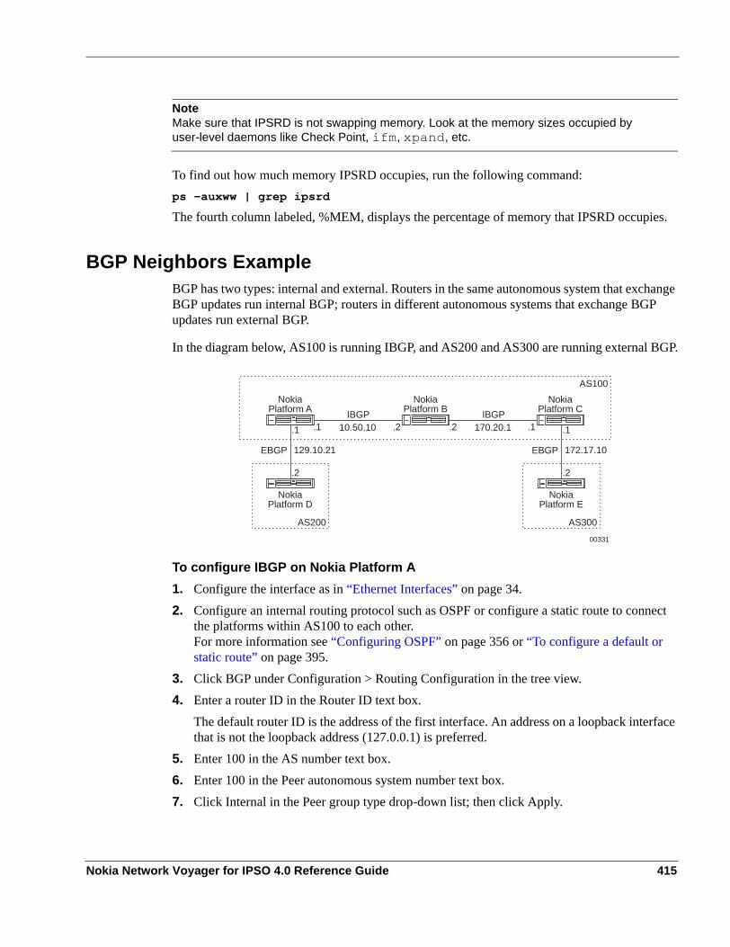
NoteMake sure that IPSRD is not swapping memory. Look at the memory sizes occupied by user-level daemons like Check Point, ifm, xpand, etc.
To find out how much memory IPSRD occupies, run the following command:ps -auxww | grep ipsrd
The fourth column labeled, %MEM, displays the percentage of memory that IPSRD occupies.
BGP Neighbors ExampleBGP has two types: internal and external. Routers in the same autonomous system that exchange BGP updates run internal BGP; routers in different autonomous systems that exchange BGP updates run external BGP.
In the diagram below, AS100 is running IBGP, and AS200 and AS300 are running external BGP.
To configure IBGP on Nokia Platform A1. Configure the interface as in “Ethernet Interfaces” on page 34.2. Configure an internal routing protocol such as OSPF or configure a static route to connect
the platforms within AS100 to each other. For more information see “Configuring OSPF” on page 356 or “To configure a default or static route” on page 395.
3. Click BGP under Configuration > Routing Configuration in the tree view. 4. Enter a router ID in the Router ID text box.
The default router ID is the address of the first interface. An address on a loopback interface that is not the loopback address (127.0.0.1) is preferred.
5. Enter 100 in the AS number text box.6. Enter 100 in the Peer autonomous system number text box.7. Click Internal in the Peer group type drop-down list; then click Apply.
NokiaPlatform A
NokiaPlatform D
NokiaPlatform B
AS100
IBGP
EBGP
00331
10.50.10
129.10.21
IBGP170.20.1.1.1 .2
.2
.2
NokiaPlatform C
.1 .1
AS200
NokiaPlatform E
EBGP 172.17.10
.2
AS300
Nokia Network Voyager for IPSO 4.0 Reference Guide 415

9
8. Enter 10.50.10.2 in the Add remote peer IP address edit box; then click Apply.9. Configure an inbound route filter for AS 100 according to “BGP Route Inbound Policy
Example” on page 446
To configure IBGP on Nokia Platform B1. Configure the interface as in “Configuring an Ethernet Interface”.2. Configure an internal routing protocol such as OSPF or configure a static route to connect
the platforms in AS100 to each other. For more information see “Configuring OSPF” on page 356or “To configure a default or static route” on page 395
3. Click BGP under Configuration > Routing Configuration in the tree view. 4. Enter a router ID in the ROUTER ID text box.
The default router ID is the address of the first interface. An address on a loopback interface that is not the loopback address (127.0.0.1) is preferred.
5. Enter 100 in the AS number edit box.6. Enter 100 in the Peer autonomous system number text box.
7. Enter 10.50.10.1 in the Add remote peer IP address text box; then click Apply.8. Enter 170.20.1.1 in the Add remote peer IP address text box; then click Apply.9. Configure an inbound route filter for AS100 according to “BGP Route Inbound Policy
Example.”
To configure IBGP on Nokia Platform C1. Configure the interface as in “Configuring an Ethernet Interface”.2. Configure an internal routing protocol such as OSPF or configure a static route to connect
the platforms in AS100 to each other. For more information, see “Configuring OSPF” on page 356 or “To configure a default or static route.”
3. Click BGP under Configuration > Routing Configuration in the tree view. 4. Enter a router ID in the ROUTER ID edit box.
The default router ID is the address of the first interface. An address on a loopback interface that is not the loopback address (127.0.0.1) is preferred.
5. Enter 100 in the AS number text box.6. Enter 100 in the Peer autonomous system number text box.7. Click Internal in the Peer group type drop-down list; then click Apply.8. Enter 170.20.1.2 in the Add remote peer IP address text box; then click Apply.9. Configure an inbound route policy for AS100 according in “BGP Route Inbound Policy
Example.”
To configure Nokia Platform C as an IBGP peer to Nokia Platform A10. Click BGP under Configuration > Routing Configuration in the tree view.
416 Nokia Network Voyager for IPSO 4.0 Reference Guide

11. Enter 10.50.10.1 in the Add remote peer IP address text box12. Click Apply.
To configure Nokia Platform A as an IBGP peer to Nokia Platform C1. Click Config on the home page.2. Click the BGP link in the Routing Configuration section.3. Enter 170.20.1.1 in the Add remote peer IP address text box4. Click Apply.
To configure EBGP on Nokia Platform A1. Configure the interface on Nokia Platform A as in “Ethernet Interfaces.”2. Click BGP under Configuration > Routing Configuration in the tree view. 3. Enter 200 in the Peer autonomous system number text box.4. Click External in the Peer group type drop-down list; then click Apply.5. Enter 129.10.21.2 in the Add Remote Peer IP Address text box; then click Apply.6. Configure route redistribution policy according to “Redistributing Routes to BGP” on page
439.7. Configure an inbound route filter according to “BGP Route Inbound Policy Example.”
To configure EBGP on Nokia Platform C1. Click BGP under Configuration > Routing Configuration in the tree view of Platform C.2. Enter 300 in the AS number text box.3. Click External in the Peer group type drop-down list; then click Apply.4. Enter 172.17.10.2 in the Add remote peer IP address text box; then click Apply.5. Configure route redistribution policy according to “Redistributing Routes to BGP” on page
407.6. Configure an inbound route filter according to “BGP Route Inbound Policy Example” on
page 446 to allow Nokia Platform C to accept routes from its EBGP peer.
To configure EBGP on Nokia Platform D1. Configure the interface as in “Ethernet Interfaces.”2. Click BGP under Configuration > Routing Configuration in the tree view. 3. Enter a router ID in the Router ID text box.
The default router ID is the address of the first interface. An address on a loopback interface that is not the loopback address (127.0.0.1) is preferred.
4. Enter 200 in the AS Number text box.5. Enter 100 in the Peer Autonomous System Number text box
Nokia Network Voyager for IPSO 4.0 Reference Guide 417

9
6. Click External in the Peer group type drop-down window; then click Apply.7. Enter 129.10.21.1 in the Add remote peer IP address text box; then click Apply.8. Configure route inbound policy according to “BGP Route Inbound Policy Example.”9. Configure route redistribution policy according to “Redistributing Routes to BGP” on page
40710. Configure an inbound route filter according to “BGP Route Inbound Policy Example.”
To configuring EBGP on Nokia Platform E1. Configure the interface as in “Ethernet Interfaces.”2. Click BGP under Configuration > Routing Configuration in the tree view. 3. Enter 300 in the AS number edit box.4. Enter 100 in the Peer autonomous system number text box.5. Click External in the Peer group type drop-down list; then click Apply.6. Enter 172.17.10.1 in the Add remote peer IP address edit box; then click Apply.7. Configure route inbound policy according the “BGP Route Inbound Policy Example” on
page 446.8. Configure route redistribution policy according to “Redistributing Routes to BGP” on page
407.9. Configure an inbound route filter according to “BGP Route Inbound Policy Example” on
page 446.
VerificationTo verify that you configured BGP neighbors correctly, run the following command in iclid: show bgp neighbor
For more information about this command, see to “Viewing Routing Protocol Information.”
Path Filtering Based on Communities Example
NoteTo filter BGP updates based on peer AS numbers, see “To configure route inbound policy on Nokia Platform D based on an autonomous system number.”
To filter BGP updates based on community ID or special community, specify an AS number along with the community ID or the name of one of the following possible special community attributes: no export, no advertise, no subconfed, or none.1. Click the Advanced BGP options link.2. Click on in the Enable Communities field, then click Apply.
418 Nokia Network Voyager for IPSO 4.0 Reference Guide

3. Follow the steps described in the “To configure route inbound policy on Nokia Platform D based on an autonomous system number” example.
4. Enter the community ID or the name of one of the special attributes in the Community ID/Special community text box, then click Apply.
5. Click on button in the Redistribute All Routes field or enter specific IP prefixes to redistribute as described in the “To configure route inbound policy on Nokia Platform D based on an autonomous system number” example, then click Apply.
BGP Multi Exit Discriminator ExampleMulti Exit Discriminator (MED) values are used to help external neighbors decide which of the available entry points into an AS is preferred. A lower MED value is preferred over a higher MED value.
In the above diagram, MED values are being propagated with BGP updates. This diagram shows four different configurations.
To configure Default MED for Nokia Platform DTo configure MED Values for all peers of AS200To configure MED Values for each external BGP peer for Nokia Platform DTo configure MED Values and a route redistribution policy on Nokia Platform D
To configure Default MED for Nokia Platform D1. Click BGP under Configuration > Routing Configuration in the tree view. 2. Configure EBGP peers in AS100 and AS200 according to the “BGP Neighbors Example.”3. Click the Advanced BGP Options link on the main BGP page.
This action takes you to the Advanced Options for BGP page.4. In the Miscellaneous settings field, enter a MED value in the Default MED edit box; then
click Apply.5. Click Save to make your changes permanent.
This MED value is propagated with all of the BGP updates that are propagated by Nokia Platform D to all of its EBGP peers in AS100 and AS200.
NokiaPlatform B
NokiaPlatform A
NokiaPlatform C
NokiaPlatform D
EBGP
EBGP
00339
AS100 AS200
AS4
Nokia Network Voyager for IPSO 4.0 Reference Guide 419

9
To configure MED Values for all peers of AS2001. Click BGP under Configuration > Routing Configuration in the tree view. 2. Configure EBGP peers in AS100 and AS200 according to the “BGP Neighbors Example.”3. Click Advanced BGP Options link on the main BGP page.
This action takes you to the Advanced Options for BGP page.4. Go to the configuration section for the AS4 routing group. Enter 100 in the MED text box
for the AS4 routing group.Setting a MED value here propagates updates from all peers of AS4 with this MED value.
NoteSetting an MED value for all peers under the local AS overwrites the default MED setting of the respective internal peers.
To configure MED Values for each external BGP peer for Nokia Platform D1. Click BGP under Configuration > Routing Configuration in the tree view. 2. Configure EBGP peers in AS100 and AS200 according to the “BGP Neighbors Example.”3. Click the link for the peer IP address for Nokia Platform A under AS100.4. Enter 100 in the MED sent out text box.5. Click on in the Accept MED from external peer field; then click Apply.6. Click the link for the peer IP address for Nokia Platform B under AS100.7. Enter 200 in the MED sent out text box.8. Click on in the Accept MED from external peer field; then click Apply.9. Click the link for the peer IP address for Nokia Platform C under AS200.10. Enter 50 in the MED sent out text box.11. Click on in the Accept MED from external peer field; then click Apply.12. Click Save to make your changes permanent.
This configuration allows Nokia Platform D to prefer Nokia Platform A (with the lower MED value of 100) over Nokia Platform B (with the higher MED value of 200) as the entry point to AS100 while it propagates routes to AS100. Similarly, this configuration propagates routes with an MED value of 50 to AS200, although no multiple entry points exist to AS200.
To configure MED Values and a route redistribution policy on Nokia Platform D1. Click BGP under Configuration > Routing Configuration in the tree view. 2. Configure EBGP peers in AS100 and AS200 according to the “BGP Neighbors Example.”3. Click the Route Redistribution link the Routing Configuration section.4. Click the BGP link in the Redistribute to BGP section.
420 Nokia Network Voyager for IPSO 4.0 Reference Guide

5. Enter 100 in MED edit box next to the Enable redistribute bgp routes to AS100 field.6. Enter necessary information for route redistribution according to the “BGP Multi Exit
Discriminator Example”; then click Apply.7. Click Save to make your changes permanent.
Setting an MED value along with route redistribution policy allows Nokia Platform D to redistribute all routes to AS100 with an MED value set to 100.
NoteSetting an MED value along with route redistribution overwrites the MED value for the external BGP peer for Nokia Platform D.
VerificationTo verify that you configured BGP MED values correctly, run the following commands in iclid. show route
show bgp neighbor <peerid> advertised
show route bgp metrics
For more information on these commands, see “Viewing Routing Protocol Information.”
Changing the Local Preference Value Example
This example shows how to set up two IBGP peers, and how to configure routes learned using Nokia Platform A to have a higher local preference value over Nokia Platform B (which has a default local preference value of 100).1. Configure the interface as in “Ethernet Interfaces.”2. Click IGBP under Configuration > Routing Configuration in the tree view. 3. Enter 100 in the AS number text box; then click Apply.
NokiaPlatform A
NokiaPlatform C
NokiaPlatform B
IBGP
EBGP
EBGP
00332
20.10.10.2/24
20.10.10.1/24
20.10.5.1/2420.10.5.2/24
NokiaPlatform D
20.10.15.2/2420.10.5.1/24
AS100 AS676
AS342
Nokia Network Voyager for IPSO 4.0 Reference Guide 421

9
To configure an IBGP peer for Nokia Platform B1. Enter 100 in the Peer Autonomous System Number text box.2. Click Internal in the Peer Group type drop-down list; then click Apply.3. Enter 20.10.10.2 in the Add Remote Peer IP Address text box; then click Apply.
To set the local preference value for an IBGP peer1. Click Up to take you back to the main Config page for Network Voyager.
Click the Inbound Route Filters link in the Routing Configuration section.2. Click Based on Autonomous System Number.3. Enter 512 (or any unique number in the range of 512 to 1024) in the Import ID text box.4. Enter 100 in the AS text box.5. Enter 200 in the LocalPref text box.6. Click Apply.7. Click Accept in the All Routes from BGP AS 100 field; then click Apply.
To configure the static routes required for an IBGP session1. Click Static Routes under Configuration > Routing Configuration in the tree view. 2. Enter 10.10.10.0 in the New static route text box.3. Enter 24 in the Mask length text box.4. Enter 20.10.10.2 in the Gateway text box; then click Apply.
To configure the static routes required for Nokia Platform B1. Configure the interface as in “Ethernet Interfaces.”1. Click BGP under Configuration > Routing Configuration in the tree view. 2. Enter 20.10.10.2 in the Router ID text box.3. Enter 100 in the AS number text box.4. Enter 20.10.10.1 in the Add remote peer ip address text box, then click Apply.5. Click Top button at the top of the configuration page.6. Click the Static Routes link in the Routing Configuration section.7. Enter 10.10.10.0 in the New Static Route text box.8. Enter 24 in the Mask Length text box.9. Enter 20.10.10.1 in the Gateway text box; then click Apply.
422 Nokia Network Voyager for IPSO 4.0 Reference Guide

BGP Confederation Example
In the above diagram, all the routers belong to the same Confederation 65525. Nokia platform A and Nokia platform B belong to routing domain ID 65527, Nokia platform C and Nokia platform D belong to routing domain ID 65528, and Nokia platform E belongs to routing domain ID 65524. In this example, you configure Nokia platform B and Nokia platform C as members of Confederation 65525 and as members of separate routing domains within the confederation. You also configure each platform as confederation peers to Nokia platform E, which has a direct route to the external AS.
Configuring Nokia Platform C1. Set up the confederation and the routing domain identifier.
a. Click BGP under Configuration > Routing Configuration in the tree view. b. Click Advanced BGP Options.c. Enter 65525 in the Confederation text box.d. Enter 65528 in the Routing domain identifier text box; then click Apply.
2. Create confederation group 65524.a. Click BGP under Configuration > Routing Configuration in the tree view. b. Click Advanced BGP Options.c. Enter 65524 in the Peer Autonomous System Number text box.d. Click Confederation in the Peer Group Type drop-down list; then click Apply.Define properties for the above group.e. Click On in the All field.
NokiaPlatform A
NokiaPlatform B
NokiaPlatform E
00333
192.168.35
192.168.30
To external AS
AS65524Confed 65525
AS65527Confed 65525
AS65528Confed 65525
AS65525
.1
.1 .1
.2
.2
NokiaPlatform D
NokiaPlatform C
192.168.45
.1
.2
.2
192.168.40
Nokia Network Voyager for IPSO 4.0 Reference Guide 423

9
f. Click On in the All Interfaces field; then click Apply.g. Enter 192.168.40.1 in the Add a new peer text box; then click Apply.
3. Create confederation group 65528.a. Click BGP under Configuration > Routing Configuration in the tree view. b. Enter 65528 in the Peer Autonomous System Number text box.c. Click Confederation in the Peer Group Type drop-down list; then click Apply.Define properties for the above group.d. Click on in the all field.e. Click on in the All Interface field; then click Apply.f. Enter 192.168.45.1 in the Add a new peer text box; then click Apply.
4. Define BGP route inbound policy by using regular expressions for any AS path and from any origin.a. Click BGP under Configuration > Routing Configuration in the tree view. b. Click the Based on ASPath Regular Expressions link.c. Enter 1 in the Import ID text box and enter .* in the ASPATH Regular Expression text
box; then click Apply.d. Click On in the Import All Routes From AS Path field; then click Apply.
5. Define route redistribution.a. Click Route Redistribution under Configuration > Routing Configuration in the tree
view. b. Click the BGP link in the Redistribute to BGP section.c. Click 65528 in the Redistribute to Peer AS drop-down list.d. Click 65524 in the From AS drop-down list; then click Apply.e. Click On in the Enable Redistribution of Routes From AS 65524 into AS 65528 field;
then click Apply.f. Click On in the all BGP AS 65524 routes into AS 65528; then click Apply.g. Click Save.
Configuring Platform B1. Set up the confederation and the routing domain identifier.
a. Click BGP under Configuration > Routing Configuration in the tree view. b. Click Advanced BGP Options.c. Enter 65525 in the Confederation text box.d. Enter 65527 in the Routing domain identifier text box; then click Apply.
424 Nokia Network Voyager for IPSO 4.0 Reference Guide

2. Create confederation group 65524.a. Click BGP under Configuration > Routing Configuration in the tree view. b. Click the Advanced BGP Options link.c. Enter 65524 in the Peer Autonomous System Number text box.d. Click Confederation in the Peer Group Type drop-down list; then click Apply.Define properties for the above group.e. Click On in the All field.f. Click On in the All Interfaces field; then click Apply.g. Enter 192.168.30.1 in the Add a new peer text box; then click Apply.
3. Create confederation group 65527.a. Click BGP under Configuration > Routing Configuration in the tree view. b. Enter 65528 in the Peer Autonomous System Number text box.c. Click Confederation in the Peer Group Type drop-down list; then click Apply.Define properties for the above group.d. Click On in the All field.e. Click On in the All Interface field; then click Apply.f. Enter 192.168.35.1 in the Add a new peer text box; then click Apply.
4. Define BGP route inbound policy by using regular expressions for any AS path and from any origin.a. Click BGP under Configuration > Routing Configuration in the tree view. b. Click the Based on ASPath Regular Expressions link.c. Enter 1 in the Import ID text box and enter .* in the ASPATH Regular Expression text
box; then click Apply.d. Click On in the Import All Routes from AS path field; then click Apply.
5. Define route redistribution.a. Click Route Redistribution under Configuration > Routing Configuration in the tree
view. b. Click the BGP link in the Redistribute to BGP section.c. Click 65528 in the Redistribute to Peer AS drop-down list.d. Click 65524 in the From AS drop-down list; then click Apply.e. Click On in the Enable Redistribution of Routes From AS 65524 Into AS 65527 field;
then click Apply.f. Click On in the All BGP AS 65524 Routes Into AS 65528 field; then click Apply.g. Click Save to make your changes permanent.
Nokia Network Voyager for IPSO 4.0 Reference Guide 425

9
Route Reflector ExampleThis example shows configuration for setting up route reflection for BGP. Route reflection is used with IBGP speaking routers that are not fully meshed.
In the above diagram, router Nokia platform A is on AS 65525, and routers Nokia platform B, Nokia platform C, and Nokia platform D are in AS 65526. This example shows how to configure Nokia platform B to act as a route reflector for clients Nokia platform C and Nokia platform D: You then configure platforms C and D and IBGP peers to platform D, as the example shows. You configure inbound route and redistribution policies for AS 65526.
Configuring Platform B as Route Reflector1. Assign an AS number for this router.
a. Click BGP under Configuration > Routing Configuration in the tree view. b. Enter 65526 in the AS number text box; then click Apply.
2. Create an external peer group.a. Click BGP under Configuration > Routing Configuration in the tree view. b. Click Advanced BGP Options.c. Enter 65525 in the Peer Autonomous System Number text box.d. Click External in the Peer Group Type drop-down list; then click Apply.
3. Enter the peer information.a. Click BGP under Configuration > Routing Configuration in the tree view. b. Click Advanced BGP Options.c. Enter 192.168.10.2 in the Add Remote Peer IP Address text box under the AS65525
External Group; then click Apply.4. Create an internal group.
a. Click BGP under Configuration > Routing Configuration in the tree view. b. Click Advanced BGP Options.c. Enter 65526 in the Peer auto autonomous system number text box.
NokiaPlatform A
00334
AS65525 AS65526
NokiaPlatform B192.168.10
192.168.20 192.168.30
.2
.2.2
.1.1 .1
NokiaPlatform D
NokiaPlatform C
Route reflector
Client Client
IBGP
EBGP
426 Nokia Network Voyager for IPSO 4.0 Reference Guide

d. Select Internal in the Peer group type drop-down list; then click Apply.5. Configure parameters for the group.
a. Click BGP under Configuration > Routing Configuration in the tree view. b. Click Advanced BGP Options.c. Click On in the All field.
This option covers all IGP and static routes.d. Click On in the All Interfaces field; then click Apply.
6. Enter the peer information.a. Click BGP under Configuration > Routing Configuration in the tree view. b. Click the Advanced BGP Options link.c. Enter 192.168.20.2 in the Add remote peer ip address text box under the AS65526
routing group.d. Select Reflector Client from the Peer type drop-down list; then click Apply.e. Click BGP under Configuration > Routing Configuration in the tree view. f. Click the Advanced BGP Options link.g. Enter 192.168.30.2 in the Add remote peer ip address text box under the AS65526
routing group.h. Select Reflector Client from the Peer type drop-down list; then click Apply.
Configuring Platform C as IBGP Peer of Platform B1. Click BGP under Configuration > Routing Configuration in the tree view on Platform C.2. Enter a router ID in the Router ID text box.
The default router ID is the address of the first interface. An address on a loopback interface that is not the loopback address (127.0.0.1) is preferred.
3. Enter 65526 in the AS Number text box.4. Enter 65526 in the Peer Autonomous System Number text box.5. Click Internal in the Peer group type drop-down list; then click Apply.6. Enter 192.168.20.1 in the Add remote peer IP address text box; then click Apply.7. Click Save to make your changes permanent.
Configuring Platform D as IBGP Peer of Platform B1. Click BGP under Configuration > Routing Configuration in the tree view on Platform D.2. Enter a router ID in the Router ID text box.
The default router ID is the address of the first interface. An address on a loopback interface that is not the loopback address (127.0.0.1) is preferred.
3. Enter 65526 in the AS Number text box.
Nokia Network Voyager for IPSO 4.0 Reference Guide 427

9
4. Enter 65526 in the Peer Autonomous System Number text box.5. Click Internal in the Peer Group Type drop-down list; then click Apply.6. Enter 192.168.30.1 in the Add remote peer IP address text box; then click Apply.7. Click Save to make your changes permanent.
Configuring BGP Route Inbound Policy on Platform B1. Click Inbound Route Filters under Configuration > Routing in the tree view.2. Click the Based on Autonomous System Number link.3. Enter 512 in the Import ID text box and enter 65526 in the AS edit box; then click Apply.4. Click Accept in the All BGP Routes From AS 65526 field; then click Apply.5. Enter 513 in the Import ID edit box and enter 65525 in the AS edit box; then click Apply.6. Click Accept in the All BGP Routes From AS 65525 field; then click Apply.7. Click Save to make your changes permanent.
Configuring Redistribution of BGP Routes on Platform BComplete this procedure to redistribute BGP routes to BGP that section a different AS. This is equivalent to configuring an export policy. In this example, as the diagram shows, platform B, which is part of AS 65526, is an EBGP peer to platform A, which belongs to AS 65525.1. Click Route Redistribution under Configuration > Routing in the tree view.2. Click the BGP Routes Based on AS link in the Redistribute to BGP section.3. Select 65526 in the Redistribute to Peer AS drop-down list and select 65525 in the From AS
drop-down list.4. Click On in the Enable Redistribute BGP Routes From AS 65525 Into AS 65526 field; then
click Apply.5. Click Accept in the All BGP ASPATH 65525 Routes Into AS 65526 field; then click Apply.6. Select 65525 in the Redistribute to Peer AS drop-down list and select 65526 in the From AS
drop-down list.7. Click On in the Enable Redistribute BGP Routes From AS 65526 Into AS 65525 field; then
click Apply.8. Click Accept in the All BGP ASPATH 65526 Routes Into AS 65525 field; then click Apply.9. Click Save to make your changes permanent.
BGP Community ExampleA BGP community is a group of destinations that share the same property. However, a community is not restricted to one network or AS.
428 Nokia Network Voyager for IPSO 4.0 Reference Guide

Communities are used to simplify the BGP inbound and route redistribution policies. Each community is identified by either an ID or one of the following special community names: no export, no advertise, no subconfed, or none.
NoteSpecify the community ID and the AS number in order to generate a unique AS number-community ID combination.
To restrict incoming routes based on their community values, see “Path Filtering Based on Communities Example.”To redistribute routes that match a specified community attribute, append a community attribute value to an existing community attribute value, or both.
NoteThe examples that follows is valid only for redistributing routes from any of the specified routing protocols to BGP. For example, configuring community-based route redistribution policy from OSPF to BGP automatically enables the same community-based redistribution policies for all of the other configured policies. In such an example, if you configure a route redistribution policy for OSPF to BGP, these changes also propagate to the redistribution policy for the interface routes into BGP.
1. Follow the steps in the “Redistributing OSPF to BGP Example.”2. Match the following ASes with the following community IDs—AS 4 with community ID 1
(4:1), AS 5 with community ID 2 (5:2), AS with no export—by entering the AS values in the AS text box and the community IDs in the Community ID/Special community text box; then click Apply.
NoteMatching an AS with the no export option only matches those routes that have all of the preceding AS number and community ID values.
3. To append an AS number and community ID combination to the matched routes, click on in the Community field; then click Apply.
4. Match AS 6 with community ID 23 (6:23) by entering 6 in the AS edit box and 23 in the Community ID/Special community text box; then click Apply.
5. Match AS with no advertise; then click Apply.
NoteMatching an AS with the no advertise option appends the community attribute with the values described in step 2. Thus, all of the routes with the community attributes set to 4:1, 5:2, and no export are redistributed with the appended community attributes 4:1, 5:2, no export, 6:23, and no advertise.
Nokia Network Voyager for IPSO 4.0 Reference Guide 429

9
EBGP Load Balancing Example: Scenario #1Loopback interfaces are used to configure load balancing for EBGP between two ASes over two parallel links. This example consists of the following:
Enabling BGP functionConfiguring loopback addressesAdding static routesConfiguring peersConfiguring inbound and route redistribution policies
In the following diagram: Nokia Platform A is in autonomous system AS100, and Nokia Platform B is in autonomous system AS200. Nokia Platform A has a loopback address of 1.2.3.4, and Nokia Platform B has a loopback address of 5.6.7.8.
Configuring a Loopback Address on Platform A1. Configure the interface as in “Ethernet Interfaces.”2. Click Interface Configuration under Configuration in the tree view.3. Click the Logical Address Loopback link.4. Enter 1.2.3.4 in the New IP Address text box; then click Apply.
Configuring a Loopback Address on Platform B1. Configure the interface as in “Ethernet Interfaces.”2. Click Interface Configuration under Configuration in the tree view.3. Click the Logical Address Loopback link.4. Enter the 5.6.7.8 in the New IP address text box; then click Apply.
Configuring a Static Route on Platform A1. Click Static Routes under Configuration > Routing in the tree view.2. Enter 5.6.7.8 in the New static route text box to reach the loopback address of Platform B.3. Enter 32 in the Mask length edit box; then click Apply.
AS100
00335
NokiaPlatform A
AS200Nokia
Platform B
Loopback1.2.3.4
Loopback5.6.7.8
129.10.1.1
129.10.2.1
129.10.1.2
129.10.2.2
430 Nokia Network Voyager for IPSO 4.0 Reference Guide

4. Enter 129.10.2.2 in the Additional Gateway edit box; then click Apply.5. Enter 129.10.1.2 in the Additional Gateway edit box; then click Apply.
Configuring a Static Route on Platform B1. Click Static Routes under Configuration > Routing in the tree view.2. Enter 1.2.3.4 in the New static route text box to reach the loopback address of Platform
A. 3. Enter 32 in the Mask length text box; then click Apply.4. Enter 129.10.2.1 in the Additional Gateway edit box; then click Apply.5. Enter 129.10.1.1 in the Additional Gateway text box; then click Apply.
Configuring an EBGP Peer on Platform A1. Configure an EBGP peer on Platform A as in “Ethernet Interfaces.”2. Enter 1.2.3.4 as the local address on the main BGP configuration page. Click Apply.3. Configure the inbound and route redistribution policies.4. Click the link for specific peer you configured in Step 1.
This action takes you the page that lets you configure options for that peer. 5. In the Nexthop field, click on next to EBGP Multihop to enable the multihop option; then
click Apply.6. (Optional) Enter a value in the TTL text box to set the number of hops over which the EBGP
multihop session is established. The default value is 64 and the range is 1 to 255. Click Apply.
Configuring an EBGP Peer on Platform B1. Configure an EBGP peer on Platform B as in “Ethernet Interfaces.”2. Enter 5.6.7.8 as the local address on the main BGP configuration page.3. Configure the inbound and route redistribution policies.4. Click the link for specific peer you configured in Step 1. This action takes you the page that
lets you configure options for that peer. 5. In the Nexthop field, click on next to EBGP Multihop to enable the multihop option; then
click Apply.6. (Optional) Enter a value in the TTL text box to set the number of hops over which the EBGP
multihop session is established. The default value is 64 and the range is 1 to 255. Click Apply.
Nokia Network Voyager for IPSO 4.0 Reference Guide 431

9
EBGP Load Balancing Example: Scenario #2
Configuring a Loopback Address on Platform A1. Configure the interface as in “Ethernet Interfaces.”2. Click Interfaces under Configuration > Interface Configuration in the tree view.3. Click the Logical Address Loopback link.4. Enter 1.2.3.4 in the New IP Address text box; then click Apply.
Configuring a Loopback Address on Platform B1. Configure the interface as in “Ethernet Interfaces.”2. Click Interfaces under Configuration > Interface Configuration in the tree view.3. Click the Logical Address Loopback link.4. Enter the 5.6.7.8 in the New IP Address text box; then click Apply.
Configuring OSPF on Platform A1. Click OSPF under Configuration > Routing in the tree view.2. Select the backbone area in the drop-down list for the interface whose IP address is
129.10.1.1; then click Apply.3. Select the backbone area in the drop-down list for the interface whose IP address is
129.10.2.1; then click Apply4. Enter 1.2.3.4 in the Add a new stub host column, then click Apply.
Configuring OSPF on Platform B1. Click OSPF under Configuration > Routing in the tree view.2. Select the backbone area in the drop-down list for the interface whose IP address is
129.10.1.2; then click Apply.3. Select the backbone area in the drop-down list for the interface whose IP address is
129.10.2.2; then click Apply.4. Enter 5.6.7.8 in the Add a New Stub Host column and then click Apply.
Configuring an EBGP Peer on Platform A1. Configure an EBGP peer on Platform A as in “Ethernet Interfaces.”2. Enter 1.2.3.4 as the local address on the main BGP configuration page.3. Configure the inbound and route redistribution policies.4. Click the link for specific peer you configured in Step 1. This action takes you the page that
lets you configure options for that peer.
432 Nokia Network Voyager for IPSO 4.0 Reference Guide

5. In the Nexthop field, click on next to EBGP Multihop to enable the multihop option; then click Apply.
6. (Optional) Enter a value in the TTL text box to set the number of hops over which the EBGP multihop session is established. The default value is 64 and the range is 1 to 255. Click Apply.
Configuring an EBGP Peer on Platform B1. Configure an EBGP peer on Nokia Platform B as in “Ethernet Interfaces.”2. Enter 5.6.7.8 as the local address on the main BGP configuration page.3. Configure the inbound and route redistribution policies.4. Click the link for specific peer you configured in Step 1. This action takes you the page that
lets you configure options for that peer. 5. In the Nexthop field, click on next to EBGP Multihop to enable the multihop option, and
then click Apply.6. (Optional) Enter a value in the TTL text box to set the number of hops over which the EBGP
multihop session is established. The default value is 64 and the range is 1 to 255.
7. Click Apply.
VerificationTo verify that you have configured load balancing correctly, run the following commands in iclid:show bgp neighborshow route bgp
For more information on these commands, see “Viewing Routing Protocol Information.”.
Adjusting BGP Timers Example1. Configure a BGP neighbor as in the “BGP Neighbors Example.”2. Click the link for the peer IP address to configure peer-specific parameters.3. Enter a value in seconds in the Holdtime text box.
Holdtime indicates the maximum number of seconds that can elapse between the receipt of successive keepalive or update messages by the sender before the peer is declared dead. It must be either zero (0) or at least 3 seconds. The default value is 180 seconds.
4. Enter a value in seconds in the Keepalive text box; then click Apply.BGP does not use any transport-protocol-based keepalive mechanism to determine whether peers are reachable. Instead, keepalive messages are exchanged between peers to determine whether the peer is still reachable.
Nokia Network Voyager for IPSO 4.0 Reference Guide 433

9
The default value is 60 seconds.5. To make your changes permanent, click Save.
TCP MD5 Authentication Example
Configuring TCP MD5 Authentication on Nokia Platform A1. Configure the interface as in “Ethernet Interfaces.”2. Click BGP under Configuration > Routing in the tree view.
The following two steps enable BGP function on Nokia Platform A. 3. Enter 10.10.10.1 (default is the lowest IP address on the appliance) in the Router ID text
box.4. Enter 100 in the AS number text box, then click Apply.
The following 2 steps configure the EBGP peer for Nokia Platform B.5. Enter 200 in the Peer autonomous system number text box.6. Select External in the Peer group type drop-down list; then click Apply.
The following steps configure an EBGP peer with MD5 authentication7. Enter 10.10.10.2 in the Add remote peer ip address text box; then click Apply.8. Click the 10.10.10.2 link to access the BGP peer configuration page9. Select MD5 as the authentication type from the AuthType drop-down list; then click Apply.10. Enter the MD5 shared key (test123 for example) in the Key text box; then click Apply.
Configuring BGP Route Redistribution on Nokia Platform B1. Configure the interface as in “Ethernet Interfaces.”2. Click BGP under Configuration > Routing in the tree view.
The following three steps enable BGP function on Nokia Platform B. 3. Enter 10.10.10.2 (default is the lowest IP address on the appliance) in the Router ID text
box.4. Enter 200 in the AS number edit box; then click Apply.
The following 2 steps configure the EBGP peer for Nokia Platform B.5. Enter 100 in the Peer autonomous system number text box.
AS100
00336
NokiaPlatform A
AS200Nokia
Platform B10.10.10.1/24 10.10.10.2/24EBGP
434 Nokia Network Voyager for IPSO 4.0 Reference Guide

6. Click External in the Peer group type drop-down list; then click Apply.The following steps configure an EBGP peer with MD5 authentication
7. Enter 10.10.10.1 in the Add remote peer ip address text box; then click Apply.8. Click the 10.10.10.1 link to access the BGP peer configuration page.9. Select MD5 as the authentication type from the AuthType drop-down list; then click Apply.10. Enter the MD5 shared key (test123 for example) in the Key edit box; then click Apply.
BGP Route Dampening ExampleBGP route dampening maintains a stable history of flapping routes and prevents advertising these routes. A stability matrix is used to measure the stability of flapping routes. The value of this matrix increases as routes become more unstable and decreases as they become more stable. Suppressed routes that are stable for long period of time are re-advertised again. This example consists of the following:
Enabling BGP functionEnabling weighted route dampening
1. Click BGP under Configuration > Routing in the tree view.2. Click the Advanced BGP Options link.3. Enable weighted route dampening by clicking on in the Enable Weighted Route Dampening
field; then click Apply.The following fields are displayed:
4. Enter any changes in the text boxes that correspond to the appropriate fields, then click Apply.
Field Default value Units of measurement
Suppress above 3 Number of route flaps or approximate value of the instability metric
Reuse below 2 Same as above
Max flaps 16 Same as above
Reachable decay 300 Seconds
Unreachable decay 900 Seconds
Keep history 1800 Seconds
Nokia Network Voyager for IPSO 4.0 Reference Guide 435

9
VerificationTo verify that you have configured route dampening correctly, run the following command in iclid.:show route bgp suppressedFor more information on this command, see “Viewing Routing Protocol Information.”
BGP Path SelectionThe following rules will help you understand how BGP selects paths:
If the path specifies a next hop that is inaccessible, drop the update. Prefer the path with the lowest weight. A route whose weight value is not specified is always less preferred than the path with the highest set weight value. Normally, the route with the highest set weight value is the least preferred.
NoteThe Nokia implementation of weight value differs from that of other vendors.
If the weights are the same, prefer the path with the largest local preference. If the local preferences are the same, prefer the route that has the shortest AS_path. If all paths have the same AS_path length, prefer the path with the lowest origin type (Origin IGP < EGP < Incomplete).If the origin codes are the same, prefer the path with the lowest MED attribute (if MED is not ignored).If the paths have the same MED, prefer the external path over the internal path. If the paths are still the same, prefer the path through the closest IGP neighbor. Prefer the path with the lowest IP address, as specified by the BGP router ID.
BGP-4++ ExampleThis example describes how to configure a BGP4 session over IPv6 transport. In this example, a connection is established between 2 routers (Router 1 and Router 2) in different autonomous systems over an IPv6 network to exchange both IPv4 and IPv6 routes.The following procedure describes the process, which consists of configuring the connection on each router, and then advertising the routes to Router 2.
436 Nokia Network Voyager for IPSO 4.0 Reference Guide
To configure configure a BGP4 session over IPv6 transport1. Determine whether Router 1 and Router 2 are directly connected.
a. If Router 1 and Router 2 are directly connected, use IPv6 addresses of the interface through which they are connected. If they are directly connected, you can use their link-local addresses for BGP peering. To do this, on BGP configuration page, specify the link-local address in the Add Remote Peer's Address (IPv6) text box, and then select the name of the interface by which this router is connected to the BGP peer in Outgoing Interface drop-down list.
b. If Router 1 and Router 2 are not directly connected, then verify that both routers have an IPv6 route to the IPv6 address that is used by the other router for BGP peering. You can verify this by going to the IPv6 Route Monitor page or using the show IPv6 route command.
2. Log in to Router 1 using Network Voyager and configure the connection as follows.a. Click BGP under Configuration > Routing in the tree view.b. Enter AS number of the other router.c. In the Peer Group Type drop-down list, select External.d. Click Apply.e. Under AS2 External Group, in the Add Remote Peer Address (IPv6) text box, enter the
IPv6 address of Router 2 .f. Click Apply.g. Under Peer, click on the IP address link for Router 2.
The BGP Peer <ipv6_addr> in AS2 page appears.h. Under Multicast Capabilities, select On for IPv6 Unicast. IPv4 unicast capability is
already selected by default—retain this setting.i. Click Apply.j. If Router 1 and Router 2 are not directly connected, select On for EBGP Multihop.k. Click Apply.l. To make your changes permanent, click Save. m. Repeat these steps on Router 2.
3. On Router 1, create a route map named advertise_to_as2 to advertise the routes from Router 1 to Router 2.
NoteFor information on creating and using route maps, see the CLI Reference Guide for Nokia IPSO.
Nokia Network Voyager for IPSO 4.0 Reference Guide 437

9
4. On Router 1, use this route map by executing the following CLI command to send both IPv4 and IPv6 unicast routes to AS 2.
set bgp external remote-as 2 export-routemap advertise_to_as2 preference 1 family inet-and-inet6
NoteThe actual routes sent will be based on the match conditions of the route map.
5. On Router 2, configure a routemap called accept_from_as2 to accept incomming IPv4 and IPv6 routes advertised by router 1. (BGP by default does not accept incomming routes.)
6. On Router 2, execute the following CLI command to use this route map to accept the incoming routes.
set bgp external remote-as 1 import-routemap accept_from_as2 preference 1 family inet-and-inet6
Route RedistributionRoute redistribution allows routes learned from one routing protocol to be propagated to another routing protocol. This is necessary when routes from one protocol such as RIP, IGRP, OSPF, or BGP need to be advertised into another protocol (when two or more routing protocols are configured on the same router). Route redistribution is also useful for advertising static routes, such as the default route, or aggregates into a protocol.
NoteRoute metrics are not translated between different routing protocols.
NoteYou can also use route maps to redistribute routes from one protocol to another. You can define route maps only using CLI commands. For information on route maps, see “Route Maps” on page 353 and the CLI Reference Guide.
When you leak routes between protocols, you specify routes that are to be injected and routes that are to be excluded. In the case where the prefix is redistributed, you can specify the metric to advertise. The metric is sent to the peer by certain protocols and may be used by the peer to choose a better route to a given destination. Some routing protocols can associate a metric with a route when announcing the route.For each prefix that is to be redistributed or excluded, the prefix is matched against a filter. The filter is composed of a single IP prefix and one of the following modifiers:
Normal—Matches any route that is equal to or more specific than the given prefix. This is the default modifier.Exact—Matches a route only if it equals the IP address and mask length of the given prefix.
438 Nokia Network Voyager for IPSO 4.0 Reference Guide

Refines—Matches a route only if it is more specific than the given prefix.Range—Matches any route whose IP address equals the given prefix’s IP address and whose mask length falls within the specified mask length range.
A sample route redistribution examples follow.
NoteThe Route Redistribution link contains over thirty possible route redistribution options.
The redistribute_list specifies the source of a set of routes based on parameters such as the protocol from which the source has been learned. The redistribute_list indirectly controls the redistribution of routes between protocols.The syntax varies slightly per source protocol. BGP routes may be specified by source AS. RIP and IGRP routes may be redistributed by protocol, source interface, and/or source gateway. Both OSPF and OSPF ASE routes may be redistributed into other protocols. All routes may be redistributed by AS path.When BGP is configured, all routes are assigned an AS path when they are added to the routing table. For all interior routes, this AS path specifies IGP as the origin and no ASes in the AS path. The current AS is added when the route is redistributed. For BGP routes, the AS path is stored as learned from BGP.
Redistributing Routes to BGPRedistributing to BGP is controlled by an AS. The same policy is applied to all firewalls in the AS. BGP metrics are 16-bit, unsigned quantities; that is, they range from 0 to 65535 inclusive, with zero being the most attractive. While BGP version 4 supports 32-bit unsigned quantities, IPSRD does not.
NoteIf you do not specify a redistribution policy, only routes to attached interfaces are redistributed. If you specify any policy, the defaults are overridden. You must explicitly specify everything that should be redistributed.
Nokia Network Voyager for IPSO 4.0 Reference Guide 439

9
BGP Route Redistribution ExampleRoute redistribution allows you to redistribute routes from one autonomous system into another autonomous system.
To configure BGP route redistribution on Nokia Platform D1. Click Route Redistribution under Configuration > Routing in the tree view.2. Click BGP Routes Based on AS under the Redistribute to BGP section.3. Select 100 from the Redistribute to Peer AS drop-down list.4. Select 4 from the From AS drop-down list; then click Apply.
This procedure enables route redistribution from AS 4 to AS 100. By default, all routes that are excluded from being redistributed from AS 4 are redistributed to AS 100.
To redistribute a single route1. To restrict route redistribution to route 100.2.1.0/24, enter 100.2.1.0 in the New IP prefix
to redistribute text box.2. Enter 24 in the Mask length text box; then click Apply.3. Select Exact from the Match Type drop-down list; then click Apply.
This procedure enables redistribution of route 100.2.1.0/24 from AS 4 to AS 100. No other routes are redistributed.
To redistribute all routes1. To allow all routes to redistributed, click Accept next to All BGP AS 4 routes into AS 100
field.2. Click Apply.
Redistributing Routes to RIP and IGRPRedistributing to RIP and IGRP is controlled by any one of three parameters:
NokiaPlatform B
NokiaPlatform A
NokiaPlatform C
NokiaPlatform D
EBGP
EBGP
00339
AS100 AS200
AS4
440 Nokia Network Voyager for IPSO 4.0 Reference Guide

ProtocolInterfaceGateway
If more than one parameter is specified, they are processed from most general (protocol) to most specific (gateway).It is not possible to set metrics for redistributing RIP routes into RIP or for redistributing IGRP routes into IGRP. Attempts to do this are silently ignored. It is also not possible to set the metrics for redistributing routes into IGRP.
NoteIf no redistribution policy is specified, RIP and interface routes are redistributed into RIP and IGRP, and interface routes are redistributed into IGRP. If any policy is specified, the defaults are overridden. You must explicitly specify everything that should be redistributed.
RIP version 1 assumes that all subnets of the shared network have the same subnet mask, so they are able to propagate only subnets of that network. RIP version 2 removes that restriction and is capable of propagating all routes when not sending version 1-compatible updates.
Redistributing RIP to OSPF ExampleIn this example, Nokia Platform A is connected to a RIP network and is redistributing RIP routes to and from OSPF for the Nokia OSPF Backbone. Nokia Platform D is connected to a subnet of Unix workstations that is running routed.
Noterouted is a utility that runs by default on most Unix workstations. This utility listens to RIP network updates and chooses a default route based on what is advertised. This process eliminates the need for static routes and provides route redundancy. Because routed does not send route updates, it is called a passive RIP listener. This subnet (192.168.26.64/28) is
Nokia Network Voyager for IPSO 4.0 Reference Guide 441

9
categorized as a stub network, meaning that a particular subnet does not send RIP routing updates.
To redistribute routes from the corporate RIP network to the Nokia OSPF network through Nokia Platform A
NoteMake sure that the Corporate net RIP router is advertising RIP on the interface connected to the Nokia network. It must be receiving and transmitting RIP updates. Nokia does not currently support the notion of trusted hosts for authentication of RIP routes.
1. Connect to Nokia Platform A using Network Voyager. 2. Click Route Redistribution under Configuration > Routing in the tree view.3. Click the RIP link under the Redistribute to OSPF External section.4. To redistribute all routes, click Accept in the All RIP routes into OSPF External field.
(Optional) To change the cost metric for RIP Routes into OSPF Externals, enter the new cost metric in the Metric text box, then click Apply.
00337
NokiaPlatform B
NokiaPlatform A
NokiaPlatform D
26.69/3026.66/30
NokiaPlatform C
26.73/3026.70/30
26.65/30 26.74/30
26.61/24 26.77/28
26.79/28 26.80/28
26.78/28
26.1/24
0.0.0.0/024.0/2422.0/24
Nokia OSPF Backbone
RIP to OSPF Border
RIP Network UNIX Hosts withRouted Enabled
Hub
Corporate Net
442 Nokia Network Voyager for IPSO 4.0 Reference Guide

5. To prevent 192.168.22.0/24 and other more specific routes from being redistributed into OSPF External, define a route filter to restrict only this route as follows:a. To configure this filter, enter 192.168.22.0 in the New IP prefix to redistribute text
box, and 24 in Mask length text box. Click Apply.b. Select Normal in the Match Type drop-down list. This specifies to prefer routes that are
equal to or more specific than 192.168.22.0/24.c. Click Apply.
The filter is fully configured.
To redistribute routes from the Nokia OSPF network to the Corporate RIP Network.1. Use the Network Voyager connection to Nokia Platform A you previously created.2. Click Route Redistribution under Configuration > Routing in the tree view.3. Click the OSPF link in the Redistribute to RIP section.4. To export all OSPF routes into RIP, click Accept in the All OSPF routes into RIP field; then
click Apply.(Optional) To change the cost metric for RIP Routes into OSPF Externals, enter the new cost metric in the Metric text box; then click Apply.
5. If you do not want to export all OSPF routes into RIP, click Restrict and define a route filter to advertise only certain OSPF routes into RIP.
6. Assume that Nokia Platform B has another interface not shown in the diagram and that it has two additional OSPF routes: 10.0.0.0/8 and 10.1.0.0/16. To exclude all routes that are strictly more specific than 10.0.0.0/8; that is, you want to propagate 10.0.0.0/8 itself, but you do not want to propagate the more specific route.a. To configure this filter, enter 10.0.0.0 in New IP Prefix to Import text box, and 8 in
Mask length text box; Click Apply.b. Select Refines in the Match Type drop-down list.
This specifies that you want routes that are strictly more specific than 10.0.0.0/8.c. Finally, click Restrict in the Action field. This specifies that we want to discard the routes
that match this prefix.d. Click Apply.
The filter is fully configured.
Redistributing OSPF to BGP ExampleIn the following example, Nokia Platform A is running OSPF and BGP and its local AS is 4.
Nokia Network Voyager for IPSO 4.0 Reference Guide 443

9
Nokia Platform E of AS 100 and Nokia Platform A of AS 4 are participating in an EBGP session. Nokia Platform F of AS 200 and Nokia Platform D of AS 4 are also participating in an EBGP session.
To redistribute OSPF to BGP through Nokia Platform A1. Click Route Redistribution under Configuration > Routing in the tree view.2. Click the OSPF link in the Redistribute to BGP section.3. To redistribute OSPF routes into peer AS 100, select 100 from the Redistribute to Peer AS
drop-down list, then click Apply.4. (Optional) Enter the MED in the MED text box; then click Apply.5. (Optional) Enter the local preference in the LocalPref text box, then click Apply.6. To redistribute OSPF routes, enter the IP prefix in the New IP Prefix to Redistribute text box
and the mask length in Mask Length text box; then click Apply.
Redistributing Routes with OSPFIt is not possible to create OSPF intra-area or inter-area routes by redistributing routes from the IPSRD routing table into OSPF. It is possible to redistribute from the IPSRD routing table only into OSPF ASE routes. In addition, it is not possible to control the propagation of OSPF routes within the OSPF protocol.There are two types of OSPF ASE routes:
Type 1Type 2
See the OSPF protocol configuration for a detailed explanation of the two types.
00338
NokiaPlatform B
NokiaPlatform A
NokiaPlatform D
NokiaPlatform E
26.69/3026.66/30
NokiaPlatform C
26.73/3026.70/30
26.65/30 26.74/30
26.61/24
26.1/24
26.77/28
Nokia OSPF Backbone
AS4
AS100
NokiaPlatform F
26.77/28AS200
EBGPEBGP
444 Nokia Network Voyager for IPSO 4.0 Reference Guide

Inbound Route FiltersInbound route filters allow a network administrator to restrict or constrain the set of routes accepted by a given routing protocol. The filters let an operator include or exclude ranges of prefixes from the routes that are accepted into RIP, IGRP, OSPF and BGP. These filters are configured in the same way as the filters for route redistribution.
NoteYou can also use route maps to specify inbound route filters. You can define route maps only using CLI commands. For information on route maps, see “Route Maps” on page 353 and the CLI Reference Guide.
An administrator can specify two possible actions for each prefix—accept the address into the routing protocol (with a specified rank) or exclude the prefix.You can specify the type of prefix matching done for filter entries in the following ways:
Routes that exactly match the given prefix; that is, have the same network portion and prefix length.Routes that match more specific prefixes but do not include the given prefix. For example, if the filter is 10/8, then any network 10 route with a prefix length greater than 8 matches, but those with a prefix length of 8 do not match.Routes that match more specific prefixes and include the given prefix. For example, if the filter is 10/8, then any network 10 route with a prefix length greater than or equal to 8 matches.Routes that match a given prefix with a prefix length between a given range of prefix lengths. For example, the filter could specify that it match any route in network 10 with a prefix length between 8 and 16.
To configure IGP inbound filters1. Click Inbound Route Filters under Configuration > Routing in the tree view.2. Click Filter Inbound RIP Routes.
NoteAll other IGPs are configured in exactly the same way.
3. In the All Routes Action field, click either Accept or Restrict.If you select accept, routes can be rejected individually by entering their IP address and mask length in the appropriate fields. Similarly, if you select RESTRICT, routes can be accepted individually by entering their IP address and mask length in the appropriate fields.
4. If you set All Routes to accept and click Apply, the Rank field is displayed. In the Rank field you can specify the rank to a value that all routes should have. The range of values is 1 to 255.
Nokia Network Voyager for IPSO 4.0 Reference Guide 445

9
5. Enter the appropriate IP address and mask length in the New Route to Filter and Mask Length fields; then click Apply. A new set of fields is displayed adjacent to the newly entered IP address and mask length.
6. Click On or Off to enable or disable filtering of this route.7. From the Match Type field drop-down list, select Normal, Exact, Refines, or Range.8. In the Action field, click Accept or Restrict to determine what to do with the routes that
match the given filter.9. In the Rank field, enter the appropriate value, and then click Apply.10. If this completes your actions for this route filtering option, click Save.11. If this does not complete your actions for this route filtering option, begin again at step 3.
BGP Route Inbound Policy ExampleYou can selectively accept routes from different BGP peers based on a peer autonomous system or an AS path regular expression.
To configure route inbound policy on Nokia Platform D based on an autonomous system number1. Click Inbound Route Filters under Configuration > Routing in the tree view.2. Click the Based on Autonomous System Number link.3. Enter 512 in the Import ID edit box.
Import ID specifies the order in which the import lists are applied to each route. The range for filters based on AS numbers is from 512 to 1024.
4. Enter 100 in the AS text box; then click Apply.This is the AS number from which routes are to be filtered.
5. (Optional) Enter more values in the Import ID and AS text boxes to configure more inbound policies based on autonomous system numbers; then click Apply.
NokiaPlatform B
NokiaPlatform A
NokiaPlatform C
NokiaPlatform D
EBGP
EBGP
00339
AS100 AS200
AS4
446 Nokia Network Voyager for IPSO 4.0 Reference Guide

NoteBy default, all routes originating from the configures ASes are accepted.
You can accept or reject all routes from a particular AS by enabling the accept or restrict option next to the All BGP routes from AS field. 1. You also can accept or reject particular routes from AS 100 by specifying a route filter.
Route filters are specified as shown in the Route Redistribution section. Assume that you want to filter all routes that are strictly more specific than 10.0.0.0/8. In other words, allow all routes whose prefix is not 10.0.0.0/8 except for 10.0.0.0/8 itself, but exclude all routes that are more specific, such as 10.0.0.0/9 and 10.128.0.0/9.
2. To configure this filter, enter 10.0.0.0 in New IP prefix to import text box, and 8 in Mask Length text box; click Apply.
3. Select Refines in the Match type drop-down list. This specifies routes that are strictly more specific than 10.0.0.0/8.
4. Finally, click Restrict in the Action field. This specifies discard the routes that match this prefix.
5. Click Apply. The filter is fully configured.
To configure route inbound policy on Nokia Platform D based on ASPATH regular expressions1. Click Inbound Route Filters under Configuration > Routing in the tree view.2. Click the Based on ASPATH Regular Expressions link.3. Enter 500 in the Import ID edit box.
The import ID specifies the order in which the import lists are applied to each route. For route filters based on AS path regular expressions, the range of values is from 1 to 511.
4. Enter a regular expression that identifies a set of ASes that should be matched with the SPATH sequence of the route:100|200
This sequence accepts all routes whose ASPATH sequence contains 100 or 200 or both.5. Select one of the origin options from the Origin drop-down list; then click Apply.
These options detail the completeness of AS path information. An origin of IGP indicates that an interior routing protocol-learned route was learned from an interior routing protocol and is most likely complete. An origin of EGP indicates the route was learned from an exterior routing protocol that does not support AS paths, and the path is most likely incomplete. When the path information is incomplete, an origin of incomplete is used.
6. Enter a new route filter. In this example assume that you want to filter all routes that are strictly more specific than 10.0.0.0/8. In other words, allow all routes whose prefix is not 10.0.0.0/8 except for 10.0.0.0/8 itself, but exclude all routes that are more specific, such as 10.0.0.0/9 and 10.128.0.0/9.
Nokia Network Voyager for IPSO 4.0 Reference Guide 447

9
7. To configure this filter, enter 10.0.0.0 in New IP prefix to import edit box, and 8 in Mask length edit box; then click Apply.
8. Select Refines in the Match type drop-down list.This specifies routes that are strictly more specific than 10.0.0.0/8.
9. Finally, click Restrict in the Action field. This specifies to discard the routes that match this prefix.
10. Click Apply. The filter is fully configured.
BGP AS Path Filtering ExampleBGP updates restrict the routes a router learns or advertises. You can filter these updates based on ASPATH regular expressions, neighbors (AS numbers), or community IDs.To filter BGP updates based on ASPATH regular expressions, see “To configure route inbound policy on Nokia Platform D based on ASPATH regular expressions.” The following examples, however, give a more detailed description of how to create ASPATH regular expressions.
ASPATH Regular Expressions1. To accept routes that transit through AS 3662, enter the following ASPATH regular
expression in the ASPATH Regular Expression text box:(.* 3662 .*)
Select Any from the Origin drop-down list; then click Apply.2. To accept routes whose last autonomous system is 3662, enter this ASPATH regular
expression in the ASPATH Regular Expression text box:(.* 3662)
Select Any from the Origin drop-down list; then click Apply.3. To accept routes that originated from 2041 and whose last autonomous system is 701, enter
the following ASPATH regular expression in the ASPATH Regular Expression text box:2041 701
Select Any from the Origin drop-down list; then click Apply.4. To accept SPRINT (AS number 1239) routes that transit through AT&T (AS number 7018)
or InternetMCI (AS number 3561), enter the following ASPATH regular expression in the ASPATH Regular Expression text box:(1239 .* 7018 .*) | (1239 .* 3561 .*)
Select Any from the Origin drop-down window. 5. Apply.6. Click Save to make your changes permanent.
448 Nokia Network Voyager for IPSO 4.0 Reference Guide

10 Configuring Traffic Management
This chapter describes traffic management functionality, including access control lists and aggregation classes.
Traffic Management OverviewTraffic management functionality allows packet streams to be filtered, shaped, or prioritized. The prioritization mechanisms conform to RFC 2598, the Expedited Forwarding specification of the IETF DiffServ Working Group.Traffic is separated into discrete streams, or classified, through an Access Control List (ACL). Traffic is metered to conform to throughput goals with an Aggregation Class (AGC). The combination of these control blocks form the basis of the filtering, shaping, and prioritization tools. A queue class is used to implement an output scheduling discipline to prioritize traffic.Logically, the ACLs and the AGCs are placed inline to the forwarding path. You can configure ACLs and AGCs to process all incoming traffic from one or more interfaces, or to process all outgoing traffic from one or more interfaces. IPSO supports Access Control Lists for both IPv4 and IPv6 traffic.
Packet Filtering DescriptionTraffic that is classified can be filtered immediately. The actions for filtering are:
Accept—The accept action forwards the traffic.Drop—The drop action drops the traffic without any notification.Reject—The reject action drops the traffic and sends an ICMP error message to the source.
For information on how to configure a packet filter, see “Configuring ACL Rules” on page 452.
Traffic Shaping DescriptionTraffic that is classified can be shaped to a mean rate. The shaper is implemented using a token bucket algorithm; this means that you can configure a burstsize from which bursts can "borrow." Measured over longer time intervals, the traffic will be coerced to the configured mean rate. Over shorter intervals, traffic is allowed to burst to higher rates. This coercion is accomplished
Nokia Network Voyager for IPSO 4.0 Reference Guide 449

10
by adding delay to packets that must wait for more tokens to arrive in the bucket. When more bursts arrive than can be accommodated by the shaping queue, then that traffic is dropped. Both outgoing and incoming traffic streams can be shaped.To configure a shaper, see “Configuring ACL Rules” on page 452. Select shape as the action for one or more rules. See “To create an Aggregation Class” on page 456 for information about creating AGC meters. You should associate the AGC with the shaping rule(s) of the ACL.
Traffic Queuing DescriptionTraffic that is classified by an Access Control List (ACL) rule can be given preferential treatment according to RFC 2598. Higher-priority traffic must be policed to prevent starvation of lower-priority service traffic. Traffic that conforms to the configured policing rate is marked with the Differentiated Services Codepoint (DSCP). When such traffic is processed by the output queue scheduler, it receives favorable priority treatment.Some traffic is generated by networking protocols. This traffic should be given the highest queuing priority; otherwise, the link may become unstable. For this reason, the Queue Class (QC) configuration provides an internetwork control queue by default; some locally sourced traffic is prioritized to use that queue.
Prioritization is only relevant for outgoing traffic. Incoming traffic is never prioritized.Use the DSfield in the Access Control List (ACL) to set the value for marking traffic that matches a given ACL rule. The QueueSpec is used to map a flow with the output queue.To configure EF, see “Configuring ACL Rules” on page 452 for information about creating ACL rules. Choose prioritize as the action for one or more rules. Enter the appropriate values in the DSfield and QueueSpec edit boxes. See “To create an Aggregation Class” for information about creating Aggregation Class meters. You should associate the AGC with the prioritize rule(s) of the ACL.
Configuring Access Control ListsTo set up an Access Control List (ACL), you must configure the interface(s) with which you want to associate the ACL and the Bypass option. To configure an interface, see “To apply or remove an ACL to or from an interface”. The Bypass option denotes that the entire packet stream flowing out of the selected interfaces should not be classified, policed, or marked. Instead, the output queue scheduler should use the supplied IP TOS as an output queue lookup. Use the Bypass option to circumvent the classifier and policer for selected interfaces.
450 Nokia Network Voyager for IPSO 4.0 Reference Guide

To create or delete an ACL1. Depending on whether you are using IPv4 or IPv6, click the following link.
a. For IPv4 ACLs, click Access List under Configuration > Traffic Management in the tree view.
b. For IPv6 ACLs, click IPv6 Access List under Configuration > IPv6 Configuration > Traffic Management in the tree view.
2. To create an ACL, enter a name for the ACL in the Create a New Access List edit box and click Apply.The Access Control List name, Delete check box, and Bypass this Access List field appear.
3. To delete an ACL, select Delete next to the Access Control List you want to delete and click Apply.The Access Control List name disappears from the Access List Configuration page.
4. Click Save to make your changes permanent.
To apply or remove an ACL to or from an interface1. Depending on whether you are using IPv4 or IPv6, click the following link.
a. For IPv4 ACLs, click Access List under Configuration > Traffic Management in the tree view.
b. For IPv6 ACLs, click IPv6 Access List under Configuration > IPv6 Configuration > Traffic Management in the tree view.
2. Click the link for the appropriate ACL in the ACL Name field.The page for that ACL appears.
3. To apply an interface to the ACL:a. Select the appropriate interface from the Add Interfaces drop-down window. b. Select either Input or Output from the Direction drop-down window.
You can apply to an interface the same direction to both an IPv4 and an IPv6 ACL. However, you cannot apply to an interface the same direction to more than one IPv4 ACL, or to more than one IPv6 ACL.Selecting the "input" direction for a ACL with a rule whose action is set to "prioritize" is equivalent to setting the action to "skip."
NoteOnly the default rule appears in the Access Control List until you create your own rule.
c. Click Apply. The new interface appears in the Selected Interfaces section.
Nokia Network Voyager for IPSO 4.0 Reference Guide 451

10
4. To remove an ACL from an interface:a. Select Delete for the appropriate interface in the Selected Interfaces table b. Click Apply.
The interface disappears from the Selected Interfaces section.5. To make your changes permanent, click Save.
Configuring ACL RulesAn Access Control List (ACL) is a container for a set of rules, and traffic is separated into packet streams by the ACL. The content and ordering of the rules is critical. As packets are passed to an ACL, the packet headers are compared against data in the rule in a top-down fashion. When a match is found, the action associated with that rule is taken, with no further scanning done for that packet.The following actions can be associated with a rule that is configured to perform packet filtering:
AcceptDropReject
The following additional actions can also be associated with a rule:Skip—skip this rule and proceed to the next rulePrioritize—give this traffic stream preferential scheduling on outputShape—coerce this traffic’s throughput according to the set of parameters given by an aggregation class
You can configure an access list to control the traffic from one or more interfaces and each access list can be associated with incoming or outgoing traffic from each interface. However, the prioritize action is only executed on outgoing traffic. Rules can be set up to match any of these properties:
IP source addressIP destination addressIP protocolUDP/TCP source portUDP/TCP destination portTCP establishment flags—When selected, traffic matches this rule when it is part of the initial TCP handshake.Type of Service (TOS) for IPv4; Traffic Class for IPv6
The following values can be used to mark traffic:DiffServ codepoint (DSfield)Queue Specifier (QueueSpec)
452 Nokia Network Voyager for IPSO 4.0 Reference Guide

NoteThe DSfield and QueueSpec field are used to mark and select the priority level.
Masks can be applied to most of these properties to allow wildcarding. The source and destination port properties can be edited only when the IP protocol is UDP, TCP, or the keyword "any."All of these properties are used to match traffic. The packets that match a rule whose action is set to "prioritize" are marked with the corresponding DSfield and sent to the queue set by QueueSpec field. The DSfield and QueueSpec field can only be edited when the Action field is set to "prioritize."
To add a new rule to an ACL1. Depending on whether you are using IPv4 or IPv6, click the following link.
a. For IPv4 ACLs, click Access List under Configuration > Traffic Management in the tree view.
b. For IPv6 ACLs, click IPv6 Access List under Configuration > IPv6 Configuration > Traffic Management in the tree view.
2. Click the link for the appropriate Access Control List in the ACL Name field.The page for that ACL appears.
3. Click the Add New Rule Before check box. 4. Click Apply.
This rule appears above the default rule. As you create more rules, you can add rules before other rules. If you have four rules—rules 1,2,3, and 4—you can place a new rule between rules 2 and 3 by checking the Add Rule Before check box on rule 3.
5. To make your changes permanent, click Save.
Modifying a RuleRules provide filtering criteria for an access list. You can add a new rule, modify a rule, or delete an existing rule in this list.When a packet matches a rule, the rule is executed immediately and no further rule scanning is done thus rule ordering is very important. If the packet matches no user-defined rule, then the action specified by the final default rule will be taken.To modify a rule, navigate to the page for the ACL that contains the rule, as described in “To add a new rule to an ACL.”Table 27 describes the attributes of an ACL rule that you can modify. To delete a rule, select the delete check box for that rule and click Apply.
Nokia Network Voyager for IPSO 4.0 Reference Guide 453

10
Table 27 ACL Rule Attributes
Attribute Description
Action A rule action can be one of the following six actions:• Accept—Forward this traffic stream.• Drop—Silently drop all traffic belonging to this stream.• Reject—Drop all traffic in this stream and attempt to deliver an ICMP error to the source.• Skip—Skip this rule proceed to next.• Shape—Coerce the throughput of this traffic according to a set of parameters given by an
aggregation class.• Prioritize—Give this traffic stream preferential scheduling on output. When you configure
an ACL rule to use the prioritize action, you must configure an Aggregation Class (AGC).
Aggregation Class This link takes you to the Traffic Condition Configuration page, where you can view and modify existing rate shaping aggregation class configurations on the system. It also allows you to add new aggregation classes or to delete existing aggregation classes from the system.
Source IP Address Specifies the source IP address to be used for matching this rule.
Source Mask Length Specifies the source filter mask length to be used for matching this rule.
Destination IP Address Specifies the destination IP address to be used for matching this rule.
Destination Mask Length
Specifies the destination filter mask length to be used for matching this rule.
Source Port Range Specifies the source port range to be used for matching this rule.You can specify the Source Port Range only if the selected protocol is either “any,” 6, TCP, 17, or UDP.
Destination Port Range Specifies the destination port range to be used for matching this rule.You can specify the Destination Port Range only if the selected protocol is either "any," 6, TCP, 17, or UDP.
Protocol Specifies the IP protocol to be used for matching this rule.Range: 0-255 or anyDefault: Any
TCP-Establishment flag When it is selected, traffic matches this rule when it is part of the initial TCP handshake. This option applies only to IPv4 ACLs.You can specify the TCP Establishment flag only if the selected protocol is TCP, 6, or "any."
Type of Service (TOS) for IPv4Traffic Class for IPv6
Specifies the type of service to be used for matching this rule.Range: any or 0x0-0xffDefault: Any
454 Nokia Network Voyager for IPSO 4.0 Reference Guide

Configuring Aggregation ClassesAn Aggregation Class (AGC) is used to determine whether the traffic stream meets certain throughput goals. Traffic that meets these goals is conformant; traffic that does not meet these goals is non-conformant. Depending on the configuration of the classifier rules, non-conformant traffic may be delayed, policed, that is dropped, or marked. An Aggregation Class groups traffic from distinct rules and measures its throughput.You can configure an Aggregation Class with two parameters: Mean Rate—The rate, in kilobits per second (kbps), to which the traffic rate should be coerced when measured over a long interval. Burst Size—The maximum number of bytes that can be transmitted over a short interval.When you initially create an AGC, a burst of traffic is conformant—regardless of how quickly it arrives—until the size of the burst (in bytes) is equal to or larger than the burstsize you configured for the AGC. When the burst reaches the configured burstsize, traffic is non-conformant, but the AGC increases the rate at which traffic is transmitted based on the configured meanrate. Traffic that arrives consistently at a rate less than or equal to the configured meanrate will always be marked conformant and will not be delayed or dropped in the respective shaper or policer stages.
DSfield Specifies the DiffServ codepoint with which to mark traffic which matches this rule.RFC 791 states that the least significant two bits of the DiffServ codepoint are unused. Thus, the least significant two bits for any value of the DSfield that you enter in the ACL rule will be reset to 0. For example, if you enter 0xA3, it will be reset to 0xA0 and the corresponding packets will be marked as 0xA0 and not 0xA3.The DSfield and QueueSpec field can be configured only when the rule’s action is set to "prioritize."
Logical Queue Specifier (QueueSpec)
Specifies the logical queue specifier value to be used by the output scheduler for traffic matching this rule.Range: None or 0-7Default: None The DSfield and QueueSpec field can be configured only when the rule’s action is set to "prioritize."When the DSfield is set to one of the predefined codepoints, for example, Internetwork Control, EF, or best effort, then the QueueSpec field is not used.
Aggregation Class See “To associate an aggregation class with a rule” on page 456.
Table 27 ACL Rule Attributes
Attribute Description
Nokia Network Voyager for IPSO 4.0 Reference Guide 455

10
To create an Aggregation Class1. Depending on whether you are using IPv4 or IPv6, click the following link.
a. For IPv4 ACLs, click Aggregation Class under Configuration > Traffic Management in the tree view.
b. For IPv6 ACLs, click IPv6 Aggregation Class under Configuration > IPv6 Configuration > Traffic Management in the tree view.
2. Enter the following in the Create a New Aggregation Class section:A name for the aggregation class in the Name edit box.Bandwidth in the Mean Rate (kbps) edit box.Burst size in the Burst Size (bytes) edit box.
3. Click Apply.The aggregation class you have just created appears in the Existing Aggregation Classes table.
4. Click Save to make your changes permanent.To delete an aggregation class, select the Delete check box next to the aggregation class that you want to delete and click Apply. This aggregation class disappears from the Existing Aggregation Classes section.
To associate an aggregation class with a rule1. Depending on whether you are using IPv4 or IPv6, click the following link.
a. For IPv4 ACLs, click Access List under Configuration > Traffic Management in the tree view.
b. For IPv6 ACLs, click IPv6 Access List under Configuration > IPv6 Configuration > Traffic Management in the tree view.
2. Click the link for the appropriate Access Control List in the ACL Name field.The page for that Access Control List appears.
3. Select Shape or Prioritize from the Action drop-down window. 4. Click Apply.
A drop-down list appears in the Aggregation Class field.5. Select an existing aggregation class from the Aggregation Class drop-down list.
NoteIf there is no aggregation class listed, you need to create an aggregation class. Go to “To create an Aggregation Class.”
456 Nokia Network Voyager for IPSO 4.0 Reference Guide

NoteA rule treats traffic as if it were configured for "skip," if the traffic matches a rule whose action has been set to "prioritize" or "shape" and no Aggregation Class is configured.
6. Click Apply.7. Click Save to make your changes permanent.
Configuring Queue ClassesQueue classes are used to instantiate a framework, or template, for output queue schedulers. Like Access Control Lists (ACLs) they are created and configured and then associated with an interface. There are a maximum of 8 priority-level queues for a queue class. You can configure the size (in packets) of each queue level as well as the queue specifier. The queue specifier is a tag assigned by the classifier and is used as a key to look up the proper queue level. Three queue levels are pre-defined: the Internetwork Control (IC), Expedited Forwarding (EF), and Best Effort (BE) queues. You can assign the remaining queues any name and QueueSpec you want. The table below shows the values that correspond to these queue values:
When you configure an ACL rule to use the priority action, you must configure an aggregation class. This aggregation class functions as a policer, that is, non-conforming traffic will be dropped. You should configure the aggregation classes so that the aggregate of the NC and EF flows consumes no more than 50% of the output link bandwidth. This action prevents lower-priority traffic from being starved. See RFC 2598 for more information. The other policers should also be configured to prevent the lower-priority queue from being starved.Internetwork control traffic, such as routing messages and keepalives, should be configured to use the internetwork control queue so that it receives precedence over regular IP traffic. Note that locally originated internetwork control traffic is automatically sent through this queue. See RFC 791 for more information about Internetwork Control traffic.A queue class can be configured to maximize device throughput or to minimize prioritized traffic latency. The QoS functionality is not achieved without a cost. The choice of QoS with minimal latency is the most costly in terms of forwarding performance, but it allows the least amount of head-of-line blocking for high priority traffic.
Name of Queue Level Priority IETF DiffServ Codepoint Queue Specifier Value
Internetwork Control 0 0xc0 7
Expedited Forwarding 1 0xb8 6
Best Effort 7 0 0
Nokia Network Voyager for IPSO 4.0 Reference Guide 457

10
To create or delete a queue class1. Depending on whether you are using IPv4 or IPv6, click the following link.
a. For IPv4 ACLs, click Queue Class under Configuration > Traffic Management in the tree view.
b. For IPv6 ACLs, click IPv6 Queue Class under Configuration > IPv6 Configuration > Traffic Management in the tree view.
2. To create a new queue class, enter its name in the Create a New Queue Class edit box and click Apply.The new queue class appears in the Existing Queue Classes field.
3. To delete an existing queue class, select the Delete check box in the Existing Queue Classes table for the Queue class you want to delete and click Apply.The queue class disappears from the Existing Queue Classes field.
4. Click Save to make your change permanent.
To set or modify queue class configuration values1. Depending on whether you are using IPv4 or IPv6, click the following link.
a. For IPv4 ACLs, click Queue Class under Configuration > Traffic Management in the tree view.
b. For IPv6 ACLs, click IPv6 Queue Class under Configuration > IPv6 Configuration > Traffic Management in the tree view.
2. In the Existing Queue Class table, click the name of queue class you want to configure.The configuration page for that queue class appears, listing the queues in the queue class. Each queue class can have up to eight queues. Three queues are reserved for Internetwork Control, Expedited Forwarding, and Best Effort traffic.
3. For each queue you want to configure, enter the following:a. Logical Name—This name appears on the queue monitoring page.
Choose a name (with no spaces) that will allow you to identify the queue’s purpose.b. Queue Specifier—An integer used to address each queue you configure within a queue
class.c. Max Queue Length—Value for the maximum number of packets that can be queued
before packets are dropped. Enter a value of zero (0) to disable a queue. Neither the Internetwork Control nor the Best Effort queue can be disabled.
4. Click Apply5. Click Save to make your changes permanent.
458 Nokia Network Voyager for IPSO 4.0 Reference Guide

To associate a queue class with an interface1. Depending on whether you are using IPv4 or IPv6, click the following link.
a. For IPv4 ACLs, click Queue Class under Configuration > Traffic Management in the tree view.
b. For IPv6 ACLs, click IPv6 Queue Class under Configuration > IPv6 Configuration > Traffic Management in the tree view.
2. In the List of Available Physical Interfaces table, click the name physical interface with which you wish to associate a queue class.The physical interface page for the interface you selected appears.
3. To enable QoS queuing, select either Max Throughput or Min QoS Latency from the Queue Mode drop-down list.
4. Click Apply.A drop-down list appears in the Queue Class field.
5. Select the queue class you want to associate with the interface from the Queue Class drop-down list.If you do not select a queue class, the default class is used. The default queue class has two queues, Internetwork Control and Best Effort.
6. Click Apply.7. Click Save to make your changes permanent.
Configuring ATM QoSATM networks can provide different quality of service for network applications with different requirements. Unspecified Bit Rate (UBR) service does not make any traffic related guarantees. It does not make any commitment regarding cell loss rate or cell transfer delay. Constant Bit Rate (CBR) service provides continuously available bandwidth with guaranteed QoS.The IPSO implementation supports CBR channels through a mechanism on an ATM network interface card (NIC) that limits the cell rate for each virtual channel you configure. The CBR feature limits the peak cell rate for each CBR channel in the output direction only. Each ATM port supports up to 100 CBR channels with 64 kbits/sec of bandwidth resolution.
Create a QoS descriptor1. Click ATM QoS Descriptor under Configuration > Traffic Management in the tree view.2. To create an ATM QoS Descriptor, enter its name in the Create a New ATM QoS Descriptor
edit box. The category for any new ATM QoS Descriptor that you configure is set to constant bit rate (CBR). CBR limits the maximum cell output rate to adhere to the requirements on CBR traffic imposed by the network.
Nokia Network Voyager for IPSO 4.0 Reference Guide 459

10
NoteThe default ATM QoS Descriptor is set to unspecified bit rate (UBR) and cannot be modified.
3. Enter a value for the maximum cell rate to be used in the output direction on a CBR channel in the Peak Cell Rate edit box.
The Peak Cell Rate is rounded down to a multiple of 64 kilobits/sec. One cell per second corresponds to 424 bits/sec.
NoteYou can configure no more than 100 CBR channels per interface. The sum of the Peak Cell Rate of all the CBR channels on an interface cannot exceed 146Mbs.
4. Click Apply. The new ATM QoS Descriptor appears in the Existing ATM QoS Descriptors table.
5. Click Save to make your changes permanent.
To delete an ATM QoS descriptor1. Click ATM QoS Descriptor under Configuration > Traffic Management in the tree view.2. Select the Delete check box next to the name of the ATM QoS Descriptor that you want to
delete.
NoteYou can delete an existing ATM QoS Descriptor only after you dissociate it from an existing permanent virtual channel (PVC). See the steps below.
3. Click Apply.The ATM QoS Descriptor disappears from the Existing QoS Descriptors field.
4. Click Save to make your changes permanent.
To dissociate an ATM QoS Descriptor from an existing PVC 1. Click Interfaces under Configuration > Interface Configuration in the tree view.2. Click the appropriate ATM interface link in the Physical field.
The physical interface page for the interface you selected appears. 3. Click the ATM QoS Configuration link. You are now in the ATM QoS Configuration page
for the physical interface you selected. In the QoS Configured PVCs field, click the QoS Descriptor drop-down window and select Default (UBR).
4. Click Apply.5. Click Save to make your changes permanent.
460 Nokia Network Voyager for IPSO 4.0 Reference Guide

6. Click the ATM QoS Descriptors link.7. In the Existing ATM QoS Descriptors field, click the Delete check box next to the name of
the ATM QoS Descriptor that you want to delete.8. Click Apply.
The ATM QoS Descriptor disappears from the Existing QoS Descriptors field.9. Click Save to make your changes permanent.
To associate an ATM QoS Descriptor with an interface and a virtual channel1. Click Interfaces under Configuration > Interface Configuration in the tree view.2. Click the appropriate interface link in Physical field.
The physical interface page for the interface you selected appears. 3. Click the ATM QoS Configuration link.
The ATM QoS Configuration page for the physical interface you selected appears.4. Under Configure a New PVC in the VPI/VCI edit box, enter the virtual path identifier/
virtual channel identifier (VPI/VCI) of the permanent virtual channel (PVC) you want to configure.
5. Under Configure a New PVC field, click the QoS Descriptor drop-down list and select the QoS descriptor with which you want to associate the PVC you configured.
NoteYou cannot delete or modify a QoS Descriptor that has been associated with a permanent virtual channel (PVC). You must first disassociate the PVC from the QoS descriptor. See “To delete an ATM QoS descriptor” for more information.
NoteYou can change the QoS configuration of a PVC while it is being used. However, doing so results in a short break in traffic because the PVC is closed while QoS configuration values change. Afterward, the system reopens the PVC.
6. Click Apply.The name of the new PVC and ATM QoS Descriptor with which you associated the PVC appear in QoS Configured PVCs field.
7. Click Save to make your changes permanent.
Configuring Common Open Policy ServerThe Common Open Policy Server (COPS) provides a standard for exchanging policy information in order to support dynamic Quality of Service (QoS) in an IP (Internet Protocol) network. This information is exchanged between PDPs (Policy Decision Points) and PEPs
Nokia Network Voyager for IPSO 4.0 Reference Guide 461

10
(Policy Enforcement Points). The PDPs are network-based servers that decide which types of traffic (such as voice or video) receive priority treatment. The PEPs are routers that implement the decisions made by the PDPs. In the Nokia implementation, the Nokia platform functions as a PEP.
Configuring a COPS Client ID and Policy Decision PointYou must configure at least one COPS Client ID and a corresponding policy decision point, that is, policy server, for the COPS Policy Module to function. 1. Click COPS under Configuration > Traffic Management in the tree view.2. In the Configured COPS Modules section click the Diffserv PIB link.
The COPS Diffserv specific configuration page appears.3. In Diffserv PIB specific configuration section, enter the name of the new client ID. Click
Apply. To view the new client ID, click on the Client ID drop-down window. The name of the new COPS client appears in a Client ID list in the COPS Security configuration section.
NoteYou can configure multiple client IDs. Only one client ID can be active at a time.
4. To configure a COPS client, click on the Client ID drop-down list and select a client name. Click Apply.
5. Enter either the IP address or domain name the server to act as the Policy Decision Point (PDP) in the Primary PDP edit box.
6. (Optional) Enter the IP address or domain name of the server to act as the secondary Policy Decision Point (PDP) in the Secondary PDP edit box.
7. Click Apply.8. Click Save to make your changes permanent.
Configuring Security Parameters for a COPS Client IDThe Nokia implementation lets you configure send and receive key IDs for each COPS Client ID to authenticate sessions with the PDP, or policy server.1. Click COPS under Configuration > Traffic Management in the tree view.2. In the Configured COPS Modules section click the Diffserv PIB link.
The COPS Diffserv specific configuration page appears.3. In the COPS security configuration section, click on the link for the name of the COPS
Client ID for which you want to configure security. This action takes you to the COPS Security Configuration page for that client.
462 Nokia Network Voyager for IPSO 4.0 Reference Guide

4. In the Sequence Number edit box, enter a value between 1 and 2147483647 to define the sequence number used for the COPS protocol. Click Apply.
5. In the Key ID field, enter a value between 1 and 2147483647 in the Send edit box to define the send key ID used for the COPS protocol.
6. In the Key field, enter a string value of up to 64 characters in the edit box next to the Send Key ID value. This value defines the key used for the COPS protocol. Use alphanumeric characters only. Click Apply.
7. In Key ID field, enter a value between 1 and 2147483647 in the Recv edit box to define the receive key ID used for the COPS protocol.
8. In the Key field, enter a string value of up to 64 characters in the edit box next to the Recv Key ID value. This value defines the key used for the COPS protocol. Use alphanumeric characters only.
NoteYou can configure up to 5 receive key IDs.
9. Click Apply.10. Click Save to make your changes permanent.
Assigning Roles to Specific InterfacesThe Nokia COPS implementation lets you assign roles to specific interfaces. A role refers to a logical name assigned to a group of objects within a network. The role name lets you group objects to which you want to assign a particular policy. You can also assign a combination of roles to a particular logical interface. You then apply policies to role(s) and not just to a single object. 1. Click COPS under Configuration > Traffic Management in the tree view.2. In the Interface Role Combinations section, enter the name for a role in the edit box next to
the appropriate logical interface name.The role name can be up to 31 characters long. Use alphanumeric characters, the period, hyphen or underscore symbols only. Do not begin a role name with the underscore symbol.
3. Click Apply.
NoteYou can assign multiple roles to each interface. You can also assign different roles to different interfaces on the same system.
4. Click Save to make your changes permanent.
Nokia Network Voyager for IPSO 4.0 Reference Guide 463

10
Activating and Deactivating the COPS ClientYou must activate the COPS client to implement the COPS module you configure. You can deactivate the COPS client to halt the COPS module implementation.1. Click COPS under Configuration > Traffic Management in the tree view.2. Click the Start button in the COPS client field to activate the COPS client; click the Stop
button to deactivate the COPS client. 3. Click Apply.4. Click Save make your change permanent.When you deactivate the COPS client, you can maintain any existing module and role configuration. This configuration remains available if you reactivate the COPS client.
Changing the Client ID Associated with Specific Diffserv Configuration
You can change a client ID on a running system. Typically, each client ID refers to a specific policy or set of policies.1. Click COPS under Configuration > Traffic Management in the tree view.2. Click the Diffserv PIB link in the Configured COPS Module section. This action takes you
to the COPS Diffserv specific configuration page.3. In the Diffserv PIB specific configuration section, click the Client ID drop-down window
and select the client ID name you now want to run. Click Apply. The name of the client ID you selected now appears in the Client ID field.
NoteA list of all existing Client IDs appears in the COPS Security configuration section.
4. Click Save to make your change permanent.
Deleting a Client IDBefore you delete a Client ID, make sure that it is not active. Perform the following steps to deactivate a client ID before you delete it.
To disable and delete a Client ID1. Click COPS under Configuration > Traffic Management in the tree view.2. Click the Diffserv PIB link in the Configured COPS Module section.
The COPS Diffserv specific configuration page appears.3. To disable the Client ID, click the Client ID drop-down list in the DiffServ PIB specific
configuration section and select either another existing client ID name or none.
464 Nokia Network Voyager for IPSO 4.0 Reference Guide

4. In the COPS security configuration section, click the Delete check box next to the name of the client ID you want to delete.
5. Click Apply.6. Click Save to make your change permanent.
Example: Rate ShapingThe following example shows you how to limit ftp data traffic to 100 kilobits per second (kbps) with a 5000 byte burstsize on output interface eth-s2p1c0.First, you create an Access Control List.1. Click Access List under Configuration > Traffic Management in the tree view.2. To create the Access Control List, enter its name in the Create a New Access List edit box.3. Click Apply.4. Click the Add Rule Before check box next to the last rule.5. Click Apply.
6. Enter tcp in the Protocol edit box and enter 20 in both the Source or Destination Port Range edit box.
7. Click Apply.8. Select Shape from the Action drop-down window.9. Click Apply.Second, you create an Aggregation Class.1. Click on the Aggregation Class Configuration link on the Access Control List Configuration
page.2. Enter the name of the new Aggregation Class in the Name edit box in the Create a New
Aggregation Class section.3. Click Apply, and then click Save to make your change permanent.4. Enter 100 in the Meanrate (Kbps) edit box.5. Enter 5000 in the Burstsize (bytes) edit box.6. Click Apply, and then click Save to make your changes permanent.Third, you associate the Aggregation Class with the rule you set when you created the Access Control List.1. Click on the Access List Configuration link on the Aggregation Class Configuration page.2. For the rule you set up when you created the Access Control List, select the aggregation
class you created from the Aggregation Class drop-down window.3. Click Apply.4. Select eth-s2p1c0 from the Add Interfaces drop-down window, and select Output from the
Direction drop-down window.
Nokia Network Voyager for IPSO 4.0 Reference Guide 465

10
5. Click Apply.6. Click Save to make your changes permanent.
Example: Expedited ForwardingThis example illustrates the combined use of the Access Control List, Traffic Conditioning, and Queuing features.This example demonstrates how to improve the response time to Telnet sessions between client and server systems over a private WAN connection within a corporate intranet as shown in the diagram below. The WAN interfaces for Network Application Platform (Nokia Platform) A and for Network Application Platform (Nokia Platform) B are ser-s3p1. The following configuration is done both on Nokia Platform A and Nokia Platform B.
1. Save the current configuration on each Nokia Platform before you set up QoS. Doing so allows you to compare the relative performance of the QoS and non-QoS configurations.a. Click Configuration Sets under Configuration > System Management in the tree view.b. Enter pre-QoS in the Save Current State to New Configuration Database edit box.c. Click Apply, and then click Save to make your change permanent.
2. Create an Aggregation Classa. Click Aggregation Class under Configuration > Traffic Management in the tree view.b. Enter wan_1_ef in the Name edit box in the Create a New Aggregation Class section.c. Enter 100 in the Mean Rate (Kbps) edit box.d. Enter 5000 in the Burstsize (bytes) edit box.e. Click Apply, and then click Save to make your Changes permanent.
3. Create a Queue Classa. Click Queue Class link under Configuration > Traffic Management in the tree view.b. Enter wan_1_ef in the Create a New Queue Class edit box.c. Click on the link to wan_1_ef in the Existing Queue Classes section to view existing
queue class values.
00045
Client
Server
LAN LANWAN LinkNokia
Platform ANokia
Platform B
466 Nokia Network Voyager for IPSO 4.0 Reference Guide

NoteThe queue specifier associated with expedited forwarding queue is 6.
4. Associate the wan_1_ef queue class with the appropriate interface.a. Click Interfaces under Configuration > Interface Configuration in the tree view.b. Click on ser-s3p1 in the Physical column.c. In the Queue Configuration field, select Max Throughput from the Queue Mode drop-
down window.d. Click Apply.e. In the Queue Configuration field, select wan_1_ef from the Queue Class drop-down
window.f. Click Apply.g. Click Save to make your changes permanent.
5. Create a new Access Control List rule to classify, condition, and prioritize telnet traffic.a. Click Access List under Configuration > Traffic Management in the tree view.b. Enter wan_1_telnet in the Create a New Access List edit box.c. Click Apply.d. Select ser-s3p1 from the Add Interfaces drop-down window.e. Select Output from Direction drop-down window.f. Click Apply.g. In the Existing Rules for wan_1_telnet section, click on the Add New Rule Before check
box.h. Click Apply.i. Select prioritize from the Action drop-down window, and then click Apply.j. Select wan_1_ef from the Aggregation Class drop-down window, and then click Apply.k. For Nokia Platform A, enter 23 in the Destination Port Range edit box, and for Nokia
Platform B, enter 23 in the Source Port Range edit box.
NoteThe telnet port number is 23.
l. Enter tcp in the Protocol edit box; enter 0xB8 in the DSfield edit box; and enter 6 in the QueueSpec edit box.
Nokia Network Voyager for IPSO 4.0 Reference Guide 467
10
Note0xB8 is the IETF differentiated-services codepoint (in hexadecimal) for expedited forwarding traffic.
m. Click Apply, and then click Save to make your changes permanent.
To test the configuration1. Start a telnet session between the client and server.2. Check the statistics on Nokia Platform A and Nokia Platform B
a. Click Interfaces under Configuration > Interface Configuration in the tree view.b. Click on the link for ser-s3p1 in the Physical column.c. Click on the Interface Statistics link.d. Scroll down to view statistics for Queue Class wan_1_ef.
You should see values other than zero on both Nokia Platform A and Nokia Platform B for the Packets Passed and Bytes Passed counters in the Expedited Forwarding row.
3. Use the telnet session to generate traffic, and then check each Nokia Platform’s interface statistics.a. Click Interfaces under Configuration > Interface Configuration in the tree view.b. Click on the link for ser-s3p1 in the Physical column.c. Click on the Interface Statistics link.d. Examine the statistics for input and output traffic and compare them to the statistics for
Expedited Forwarding traffic.4. Start an ftp session to create heavy (non-telnet) background traffic over the WAN. Note that
the telnet session remains responsive. Use a text editor to examine a file.5. Save the QoS routing configuration (See Step 1 in the instructions for how to configure this
example), and restore the non-QoS configuration. Compare the difference in responsiveness when there is heavy WAN traffic both with and without QoS routing.
468 Nokia Network Voyager for IPSO 4.0 Reference Guide

11 Configuring Router Services
This chapter describes how to enable your system to forward broadcast traffic by enabling the IP Broadcast Helper, forward BOOTP/DHCP traffic by enabling BOOTP relay, how to enable router discovery, and how to configure for Network Time Protocol (NTP).A Nokia appliance, like any routing device, does not forward broadcast traffic outside its broadcast domain as per ethernet standards. To have your appliance forward broadcast traffic, you must enable the IP Broadcast Helper, as described in “IP Broadcast Helper” on page 471. To forward BOOTP/DHCP traffic, you must enable Bootp/DHCP Relay, as described in “BOOTP/DHCP Relay” on page 469. Both of these services listen for broadcasts on the configured interface and change them into a unicast transmission to the configured destination host.
BOOTP/DHCP RelayBOOTP/DHCP Relay extends Bootstrap Protocol (BOOTP) and Dynamic Host Configuration Protocol (DHCP) operation across multiple hops in a routed network. In standard BOOTP, all interfaces on a LAN are loaded from a single configuration server on the LAN. BOOTP Relay allows configuration requests to be forwarded to and serviced from configuration servers located outside the single LAN. BOOTP Relay has the following advantages over standard BOOTP:
It makes it possible to bootstrap load from redundant servers by allowing multiple servers to be configured for a single interface. If one of the redundant configuration servers is unable to perform its job, another takes its place.It provides load balancing by allowing different servers to be configured for different interfaces instead of requiring all interfaces to be loaded from a single configuration server.It allows more centralized management of the bootstrap loading of clients. This advantage becomes more important as the network becomes larger.
The IPSO implementation of BOOTP Relay is compliant with RFC 951, RFC 1542, and RFC 2131. BOOTP Relay supports Ethernet and IEEE 802 LANs by using canonical MAC byte ordering, that is, clients that specify Bootp htype=1: 802.3 and FDDI.When an interface configured for BOOTP Relay receives a boot request, it forwards the request to all the servers in its server list. It does this after waiting a specified length of time to see if a local server answers the boot request. If a primary IP is specified, it stamps the request with that address, otherwise it stamps the request with the lowest numeric IP address specified for the interface.
Nokia Network Voyager for IPSO 4.0 Reference Guide 469

11
Configuring BOOTP/DHCP RelayYou can use Network Voyager to enable BOOTP Relay on each interface. If the interface is enabled for relay, you can set up a number of servers to which to forward BOOTP requests. Enter a new IP address in the New Server text box for each server. To delete a server, turn it off.Table 28 describes the parameters that you can configure for BOOTP relay
To enable BOOTP relay on an Interface 1. Click BOOTP Relay under Configuration > Router Services in the tree view.2. Select On for the interface on which you want to enable BOOTP.3. Click Apply.
Additional fields appear. 4. (Optional) Enter values for one or more of the following parameters, described in Table 28,
above.Primary IP—Enter the IP address to use as the BOOTP router address.Wait Time—Enter the minimum client-elapsed time (in seconds) before forwarding a BOOTP request.New Server—Enter the IP address of the BOOTP/DHCP configuration server to which to relay BOOTP requests.
5. Click Apply.6. Repeat to relay BOOTP requests to more than one server.7. Click Save to make your changes permanent.
Table 28 BOOTP configuration parameters
Parameter Description
Primary IP If you enter an IP address in the Primary IP text box, all BOOTP requests received on the interface are stamped with this gateway address. This can be useful on interfaces with multiple IP addresses (aliases).
Wait Time Specifies the minimum number of seconds to wait for a local configuration server to answer the boot request before forwarding the request through the interface. This delay provides an opportunity for a local configuration server to reply before attempting to relay to a remote server. Set the wait time to a sufficient length to allow the local configuration server to respond before the request is forwarded. If no local server is present, set the time to zero (0).
New Server Enables forwarding of BOOTP requests to a configuration server. You can configure relay to multiple configuration servers independently on each interface. Configuring different servers on different interfaces provides load balancing, while configuring multiple servers on a single interface provides redundancy. The Server IP Address cannot be an address belonging to the local machine.
470 Nokia Network Voyager for IPSO 4.0 Reference Guide

To disable BOOTP relay on an interface1. Click BOOTP Relay under Configuration > Router Services in the tree view.2. Select Off for the interface on which you want to disable BOOTP.3. Click Apply to disable the interface.
When you click off, then apply, the BOOTP relay parameters (primary IP, wait time, and new server) disappear, however the parameters are still stored in the system. If you select On, then Apply, these parameters reappear.
4. Click Save to make your changes permanent.
IP Broadcast HelperIP Broadcast Helper is a form of static addressing that uses directed broadcasts to forward local and all-nets broadcasts to desired destinations within the internetwork. IP Broadcast Helper allows the relaying of broadcast UDP packets on a LAN as unicasts to one or more remote servers. This is useful when you relocate servers or hosts from their original common segment and still want the service to be available.
NoteFor further information, see RFC1542 section 4.
You cannot pass BOOTP UDP packets by using the IP Broadcast helper (UDP port 67). The BOOTP functionality on a router is different from generic UDP packet forwarding to a specified IP address. While the IP Broadcast Helper forwards the UDP packet to the IP address without modification, the BOOTP implementation is more complex—the client sends a broadcast BOOTP packet to the router, which sends a modified packet to the server. The router modifies the packet by inserting its IP address in the giaddr field of the BOOTP packet (this field is used by the server to identify the network where the packet originated).Table 29 describes the parameters that you can configure for IP broadcast helper.
Table 29 IP Broadcast helper configuration parameters
Parameter Description
Forward Nonlocal Allows you to forward packets that are not originated by a source that is directly on the receiving interface. When you enable Forward Nonlocal, it applies to all interfaces that are running the IP Helper service.Selecting Disabled requires that packets be generated by a source directly on the receiving interface to be eligible for relay. Enabled allows forwarding of packets even if the source is not directly on the receiving interface. The default is Disabled, which requires that packets be generated by a source directly on the receiving interface to be eligible for relay.
IP Helper Interface On/Off
Specifies whether IP helper service is running on the interface. After you select On and click the Apply button, configuration options for IP broadcast helper for the interface appear.
Nokia Network Voyager for IPSO 4.0 Reference Guide 471

11
To configure the relaying of broadcast UDP packets on your system, use the following procedure.
To configure IP broadcast helper 1. Click IP Broadcast Helper under Configuration > Router Services in the tree view.2. Click On for each interface to support IP Helper services. 3. Click Apply.
The New UDP Port field appears under that interface. 4. To add a new UDP Port to the helper services:
a. Enter the new UDP port number in the New UDP Port text box. b. Click Apply.
The UDP port appears in the table for that interface with On and Off radio buttons. To delete forwarding for a UDP service select Off and then click Apply.
5. To add a new server to a UDP port:a. Enter the new server’s IP address in the New Address for UDP Port X text box. b. Click Apply.
The server IP address appears under the UDP port. To delete forwarding for a server select Off and then click Apply.
6. Verify that each interface, UDP port, or server is enabled (On) or disabled (Off) for IP helper support according to your requirements.
7. Click Save to make your changes permanent.
Router DiscoveryThe ICMP Router Discovery protocol is an IETF standard protocol that allows hosts running an ICMP router discovery client to learn dynamically about the presence of a viable default router on a LAN. It is intended to be used instead of having hosts wiretap routing protocols such as RIP. It is used in place of, or in addition to, statically configured default routes in hosts.
UDP Port Specifies a new UDP service to be forwarded by an interface. Client UDP packets with the specified UDP port number will be forwarded to the configured server(s).
Server address Specifies the servers defined for forwarding for the interface and UDP service.
Table 29 IP Broadcast helper configuration parameters
Parameter Description
472 Nokia Network Voyager for IPSO 4.0 Reference Guide

NoteOnly the server portion of the Router Discovery Protocol is supported.
IPSO implements only the ICMP router discovery server portion, which means that a Nokia router can advertise itself as a candidate default router, but it will not adopt a default router using the router discovery protocol.The ICMP Router Discovery Service provides a mechanism for hosts attached to a multicast or broadcast network to discover the IP addresses of their neighboring routers. This section describes how you can configure a router to advertise its addresses by using ICMP Router Discovery.
Router Discovery OverviewThe router discovery server runs on routers and announces their existence to hosts. It does this by periodically multicasting or broadcasting a router advertisement to each interface on which it is enabled. These advertisements contain a list of all the router addresses on a given interface and their preference for use as a default router.Initially, these router advertisements occur every few seconds, then fall back to every few minutes. In addition, a host can send a router solicitation, to which the router responds with a unicast router advertisement, unless a multicast or broadcast advertisement is due in a moment.Each router advertisement contains an advertisement lifetime field indicating for how long the advertised addresses are valid. This lifetime is configured such that another router advertisement is sent before the lifetime expires. A lifetime of zero (0) indicates that one or more addresses are no longer valid.On systems that support IP multicasting, the router advertisements are sent by default to the all-hosts multicast address 224.0.0.1. However, you can specify the use of broadcast. When router advertisements are being sent to the all-hosts multicast address, or an interface is configured for the limited-broadcast address 255.255.255.255, all IP addresses configured on the physical interface are included in the router advertisement. When the router advertisements are being sent to a net or subnet broadcast, only the address associated with that net or subnet is included.
NoteRouter discovery is not supported when clustering is enabled.
Configuring Router DiscoveryTable 29 describes the parameters that you can configure for router discovery.
Nokia Network Voyager for IPSO 4.0 Reference Guide 473

11
To configure the router discovery services on your system, use the following procedure.
To enable router discovery services1. Click Router Discovery under Configuration > Router Services in the tree view.2. Select On for each interface to support router discovery service. 3. Click Apply.
Additional fields appear.4. (Optional) Enter values for the following parameters, described in Table 30.
Minimum Advertisement Interval Maximum Advertisement Interval
Table 30 Router discover configuration parameters
Parameter Description
Router Discovery Interface On/Off
Specifies whether ICMP router discovery is running on the interface. When you select On and click Apply, configuration options for the interface appear.
Min. Advertise Interval
Specifies the minimum time (in seconds) allowed between sending unsolicited broadcast or multicast ICMP Router Advertisements on the interface.Range: Between 3 seconds and the value of Maximum Advertisement Interval.Default: 0.75 times the value in the Maximum advertisement interval field.
Max. Advertise Interval
Specifies the maximum time (in seconds) allowed between sending unsolicited broadcast or multicast ICMP Router advertisements on the interface.Range: 4-1800 Default: 600
Advertisement Lifetime
Specifies the time (in seconds) to be placed in the Lifetime field of Router Advertisement packets sent from the interface.Range: Between the value in the Maximum advertisement interval field and 9000 seconds.Default: 3 times the values in the Maximum advertisement interval field.
Advertise Address For each IP address associated with the interface, specifies whether the address should be advertised in the Router Advertisement packets. This option applies to each address on the interface and not to the interface itself.Default: Yes
Preference Specifies the preferability of the address as a default router address, relative to other router addresses on the same subnet. The minimum value (0x80000000) is specified by the "Ineligible" button and indicates that the address is not to be used as a default router.You can also make an IP address ineligible as a default router address. Click Ineligible to remove an IP address as a possible default router address.The default is Eligible. Enter a value to indicate the level of preference for the IP address as a default router address in the text box below the Eligible button. The default is 0.
474 Nokia Network Voyager for IPSO 4.0 Reference Guide

Advertisement Lifetime5. (Optional) For each IP address on the interface, you can specify the following parameters,
described in Table 30.Advertise AddressPreference
6. Click Apply.7. Click Save to make your changes permanent.
To disable router discovery services 1. Click Router Discovery under Configuration > Router Services in the tree view.2. Click Off for each interface to disable support for router discovery service. 3. Click Apply.4. Click Save to make your changes permanent.
Network Time Protocol (NTP)Network Time Protocol (NTP) is an Internet standard protocol used to synchronize the clocks of computers in a network to the millisecond. Synchronized clock times are critical for distributed applications that require time synchronization, such as Check Point FireWall-1 Sync, and for purposes such as analyzing event logs from different devices, ensuring cron jobs execute at the correct time, and ensuring that applications that use system time to validate certificates find the correct time. NTP runs as a continuous background client program on a computer, sending periodic time requests to the servers that you configure, obtaining server time stamps and using them to adjust the client’s clock. You should configure several servers for redundancy.When you configure devices as peers, they listen to each other and move toward a common time. Peers are considered equal with each other as opposed to servers, which are considered masters. It is important that you configure several peers so that they can decide on the right time.If an NTP server or peer is not available, you can turn on the NTP reference clock to have your server configured as a source of time information. In this mode, Nokia recommends that you keep the stratum value at its default (1). The stratum value tells how far away the NTP reference clock is from a valid time source.The time server begins to provide time information 5 minutes after it is configured.
NoteIPSO does not implement SNTP.
Nokia Network Voyager for IPSO 4.0 Reference Guide 475

11
Configuring NTPYou can enable or disable NTP on your system; when NTP is active the local clock is synchronized as configured and hosts will be able to set their time through this machine.To set the time manually, see “Setting the System Time” on page 158.
To configure NTP 1. Click NTP under Configuration > Router Services in the tree view.2. Click Yes in the Enable NTP field.3. Click Apply.
The NTP configuration page appears.4. Enter the new server IP address in the Add New Server Address edit box.5. Click Apply.
The IP address for the new NTP server appears in the NTP Servers field. By default, this new server is enabled, v3 is selected, and Prefer Yes is selected. As you add other servers, you might prefer them over the initial server you configured.
NoteNokia recommends that you use the default setting of v3.
6. To add another new server, repeat step 4 and click Apply.7. (Optional) Enable the NTP reference clock by clicking Yes in the NTP Master field and
click Apply.The Stratum edit box and Clock source drop-down list appear. By default, the Stratum value is 1, and the Clock source is set to Local Clock. Nokia recommends that you keep these defaults.
8. To configure a new peer, enter the new peer IP address in the Add New Peer: Address: edit box. Click Apply.The new peer IP address appears in the NTP Peers field. By default, this new peer is enabled, v3 is selected, and Prefer Yes is selected. As you add other peers, you might prefer them over the initial peer you configured.
NoteNokia recommends that you use the default setting of v3.
9. To add another new peer, repeat step 8 and click Apply.The new peer IP address appears in the NTP Peers field. By default, this new peer is enabled, v3 is selected, and Prefer No is selected. To prefer this peer over other peers, click Prefer Yes.
476 Nokia Network Voyager for IPSO 4.0 Reference Guide

10. (Optional) Enable the NTP reference clock by clicking Yes in the NTP Master field.
NoteOnly enable the NTP reference clock if you cannot reach an NTP server.
11. Click Apply.The Stratum and Clock source fields appear. By default, the Stratum value is 1, and the Clock source is set to Local Clock. Nokia recommends that you keep these defaults.
12. Click Save to make your changes permanent.
Nokia Network Voyager for IPSO 4.0 Reference Guide 477

11
478 Nokia Network Voyager for IPSO 4.0 Reference Guide

12 Monitoring System Configuration and Hardware
This chapter provides information on monitoring your system.You can use Network Voyager to monitor many aspects of your IP security platform in order to better maintain performance and security. You can, for example, monitor state information for each interface, view the contents of IP routing tables, and generate reports on events such as throughput, bandwidth utilization, and link states over specific periods of time.
Viewing System Utilization StatisticsUse the system utilization statistics to monitor and tune the allocation of system resources. For example, if the percentage shown under file system capacity becomes a high percentage, you should take action, such as deleting old IPSO images and packages or move your log files to a remote system.To view statistical information on system utilization, click either CPU-Memory Live Utilization, Disk and Swap Space Utilization, or Process Utilization under Monitor > System Utilization in the tree view.
CPU-Memory Live UtilizationThe CPU-Memory Live Utilization page shows system resources usage, including CPU and memory usage. This page retrieves the updated CPU and memory usage every 20 seconds.The CPU Utilization summarizes the load averages, which are the number of processes in the system run queue averaged over the last 1, 5, and 15 minutes, respectively. Load averages that are high, such as over 2 in all three fields, indicate that the system is under continuous heavy load. The memory utilization summarizes memory usage in KBs. Free memory (memory that is available to the operating system) is defined as free pages + cache pages. The remainder is active memory (memory the operating system is currently using). The free memory might differ (will mostly be lower) as compared to output of a vmstat command.
Nokia Network Voyager for IPSO 4.0 Reference Guide 479

12
Disk and Swap SpaceThe Disk and Swap Space Utilization page shows system resources use, including disk and swap space use. This page retrieves the updated disk and swap space use every 20 seconds.For each file system, you can monitor the number of kilobytes used and available, the percentage of disk space being used, the number of inodes used and free, and the location where it is mounted. The inode is the internal identifier for a file and a limited number are available in a partition. A system can run out of inodes before running out of disk space. For swap space, you can monitor the name of the device, total number of swap data blocks on the device, the number of used and free swap data blocks on the device, and the type of device.
NoteYou should monitor the /config, /var, and /opt partitions, since these store the configuration files and logs and optional user software. Unlike read-only partitions, these can grow dynamically.
Monitoring Process UtilizationThe Process Utilization page shows the status of processes. You must monitor and control processes to manage CPU and memory resources.This page retrieves the updated process status every 30 seconds. When you access this page, a table displays the following fields for each process:
USER—User who initiated or executed the process.PID—Identifier used by the kernel to uniquely identify the process.%CPU—Percentage of CPU used by the process while active. This is a decaying average taken over a time period of up to the previous minute. Because the time base over which CPU utilization of the process is computed varies (processes might be very young), the sum of all CPU fields can exceed 100%.%MEM—Percentage of real memory used by the process while active.VSZ—Virtual size of the process in KBs (also called vsize).RSS—Real memory (resident set) size of the process in KBs.WCHAN—Wait channel (as a symbolic name). This is the event on which a process waits.STAT—Symbolic process state given as a sequence of letters. For example, R indicates a runnable process (R) that is a session leader (s). For more information, see the process status man page (man ps).STARTED—Time the command started.TIME—Accumulated CPU time: user plus system (alias cputime).COMMAND—Command and arguments.
480 Nokia Network Voyager for IPSO 4.0 Reference Guide

IPSO Process ManagementWhen you are troubleshooting any system, it is helpful to have an understanding of the daemons, or system processes, that are operating in the background. The process monitor (PM) monitors critical Nokia IPSO processes. The PM is responsible for:
Starting and stopping the processes under its controlAutomatically restarting the processes if they terminate abnormally
The Nokia IPSO processes that the PM monitors are listed in the following table. In addition, the PM might also monitor application package processes, such as IFWD, FWD, CPRID.
The PM frequently checks the status of the processes it monitors and typically takes less than a second to notice if a process has terminated abnormally. It then attempts to restart the process. If the process fails to start, the PM continues to try to restart it at regular intervals, with each interval increasing by a factor of two (for example, 2 seconds, 4 seconds, 8 seconds, 16 seconds, and so on). If the PM fails to start the process after 900 seconds, it stops trying. Each unsuccessful attempt is logged in the system message log. The process monitoring behavior of the PM is not user configurable.
Process Description
inetd Internet daemon. This daemon helps manage Internet services on IPSO by monitoring port numbers and handling all requests for services.
ipsrd Routing daemon. This daemon is a user-level process that constructs a routing table for the associated kernel to use for packet forwarding. With a few exceptions, IPSRD completely controls the contents of the kernel forwarding table. This daemon factors out (and separately provides) functionality common to most protocol implementations. This daemon maintains and implements the routing policy through a database.
ifm Interface management daemon. This daemon sends and receives information to and from the kernel to verify the integrity of the interface configuration.
xntpd Network time protocol daemon. This daemon sets and maintains a UNIX system time-of-day in compliance with Internet standard time servers.
monitord System monitor daemon. This daemon monitors system health, collects and stores statistical information, and displays the data on request.
httpd Web server daemon.
sshd Secure shell daemon.
xpand Configuration daemon (also called configd). This daemon processes and validates all user configuration requests, updates the system configuration database, and calls other utilities to carry out the request.
snmpd SNMP agent. Responds to queries via SNMP.
Nokia Network Voyager for IPSO 4.0 Reference Guide 481

12
Generating Monitor ReportsYou can generate reports of data collection events. To generate a report, click the link for the appropriate report under Monitor > Reports in the tree view.For information on configuring monitor reports, see “Configuring Monitor Reports” on page 177. The administrator can configure how often the data is collected, whether each data collection event is enabled or disabled, and how many hours worth of collected data are stored on the system.
Table 31 Reports
Report Description
Rate-Shaping Bandwidth Shows specific bandwidth utilization. You can use traffic shaping to implement a specific policy that controls the way data is queued for transmission. For information on creating aggregate classes and configuring traffic rules, see Chapter 10, “Configuring Traffic Management.”Inclusion of number of packets delayed and bytes delayed is configurable by the administrator. By default, both are included.
Interface Throughput Shows historical throughput for each interface.You can often use this information to optimize network performance or troubleshoot issues network traffic congestion.Inclusion of packet throughput, byte throughput, broadcast packets, and multicast packets for each interface is configurable by the administrator. By default, all are included.
Network Throughput Similar to the interface throughput report, except that the query is based on the network address rather than interface name.
Interface Link State Shows information about the link state of each interface. The first signs of problems with interfaces is frequently seen in link errors. You can use this report to determine if an interface is experiencing problems or has been incorrectly configured.
CPU Utilization Shows historical CPU utilization data, including percentages of CPU time for each of the following:• User% —Percentage of CPU time spent in User-level instructions.• Nice%—Percentage of CPU time spent in "Nice" processes.• System%—Percentage of CPU time spent in System level instructions.• Interrupt%—Percentage of CPU time spent in servicing interrupts.• Idle%—Percentage time CPU was idle.
Memory Utilization Shows historical memory utilization, including: • Active Real Memory—Kilobytes of real memory being used in a given
time interval.• Free Real Memory—Kilobytes of real memory free in a given time
interval.
482 Nokia Network Voyager for IPSO 4.0 Reference Guide

To display reports1. Click the name of the report under Monitor > Reports in the tree view.2. Under Select Report Type, select one of the following:
Hourly—Hourly report with a 1-hour display up to a maximum of 7 interval day data.Daily—Daily report with 1-day display interval up to a maximum of 35 day data.Weekly—Weekly report with 7-day display interval up to a maximum of 52 weeks.Monthly—Monthly report with 1-month display interval up to a maximum of 60 months.Detailed Search—Select a specific time period. These reports have a default data interval of one minute. The number of hours worth of data stored for detailed searches is configured by the administrator. For more information, see “Configuring Monitor Reports” on page 177.
3. For the Rate-Shaping Bandwidth report, select an aggregation class for which you want to display a report or select All Aggregates to display data for all configured aggregation classes.
NoteYou must configure an aggregation class and associate it with an access control list for the name to appear as a choice in the Aggregation Class list. For more information, see Chapter 10, “Configuring Traffic Management.”
4. For the Interface Throughput, Network Throughput, or Interface Link State reports, select All Logical or a specific interface name from the Select Interface drop-down list.
5. Under Select Format, choose Graphical View or Delimited Text. If you select Delimited Text, select Semi-Colon(;), Comma(,), or Tab from the Delimiter drop-down list.The Graphical View option displays pie and graph charts, as well as in table format. The Delimited Text option displays the report in a new page from which you can download the information.
6. Click Apply.
Monitoring System HealthThe system health links allow you to display statistics to help you monitor the status of your IP security platform. To view this information, click the appropriate link under Monitor > System Health in the tree view.
Useful System Statistics—Summarizes configuration information, including the following:Active Routes—The number of active routes configured.Packets Forwarded—The number of packets forwarded.VRRP Masters—The number of VRRP masters configured.
Nokia Network Voyager for IPSO 4.0 Reference Guide 483

12
Real Memory Used—The percentage of the real memory being used.Disk Capacity—The percentage of the disk space being used.
Interface Traffic Statistics—For each physical and logical interface, shows the current state, input and output bytes, input and output errors. For logical interfaces, also shows the type of device or virtual circuit accessed through the logical interface (for example, Ethernet, ATM, FDDI).Interface Queue Statistics—Shows the current information for interface queues, including the following:
Logical Name—The configured name of the queue.Maximum Packets—Configured maximum number of packets which can be buffered by this queue.Packets Passed—Number of packets sent from this queue to the physical interface.Bytes Passed—Number of bytes sent from this queue to the physical interface.Packets Dropped—Number of packets dropped at this queue due to lack of buffer space.Bytes Dropped—Number of bytes dropped at this queue due to lack of buffer space.
VRRP Service Statistics—Shows per-interface and per-virtual router VRRP send and receive packet statistics.
Monitoring System LogsThe system logs links allow you to display updated system logs. To view system logs, click the appropriate link under Monitor > System Logs in the tree view. To refresh the information in a log, reload the Web page.System logs include the following:
System Message Log—You can view the message log file in its entirety or select search criteria to view specific system log activity. Search criteria include:
Types of log activity—Select one or more from All, Emergency, Alerts, Critical, Errors, Warnings, Notifications, Informational or Debug Messages.MonthParticular date. You must also select a month to activate this option. Keyword. To make the keyword search case-sensitive, select the Case Sensitive check box. You can include certain zipped files in your search by clicking the appropriate check box in the Include Zipped Files in Search section.
NoteThe system log also displays messages generated by the system configuration audit log. For information configuring the audit log, see “To set the system configuration audit log” on page 164.
484 Nokia Network Voyager for IPSO 4.0 Reference Guide

Web Server Access Log—Shows information about accesses to the Network Voyager interface using HTTP or HTTPS. Messages include IP Address from which the local host did an http access to the system, user, date, time, and HTTP access command.Web Server Error Log—Shows error messages from the HTTPD Error Log File, including date and time the error occurred, transaction (type of log message), location, and contents of log message.User Login/Logout Activity—Shows login and logout activity for users. By default, activity for all user is displayed. You can view activity for a particular user by selecting the user name from the drop-down list.Management Activity Log—Shows user login activity as well as details about changes made to the IPSO configuration. The log includes a time stamp, the hostname or IP address from which the user logged in, and the config entry, which displays the entry changed in the configuration database.For more information, see “To set the system configuration audit log” on page 164.
NoteYou do not need to configure the Web Server Access log or the Web Server Error log.
Viewing Cluster Status and MembersTo view information about cluster status and members, click Clustering Monitor under Monitor in the tree view. This page summarizes information about a configured IPSO cluster, including information about cluster status and load sharing among members of the cluster. The information summary is refreshed every 30 seconds.The Cluster Status table contains the following information:
Cluster ID—ID number of the cluster. Cluster Uptime—Time since the cluster was formed. Number of Members—Current number of members in the cluster. Number Of Interfaces—Number of interfaces on which clustering is enabled. Network—Networks on which clustering is enabled. Cluster IP Address—Cluster IP Address on each network.
The Cluster Member table contains the following information:Member Id—Node ID in the cluster. IP Addr—Primary IP address of the member. Hostname—Hostname of the node. Platform—Type of platform. OS Release—Operating system version node is running. Rating—Node performance rating.
Nokia Network Voyager for IPSO 4.0 Reference Guide 485

12
Time Since Join—Time since node joined the cluster. Work Assigned (%)—Percentage of work load assigned to this node.
NoteIf your cluster is not initialized, the Cluster Monitor page contains a link to the Cluster Configuration page, which enables you to configure cluster parameters for this node.
Viewing Routing Protocol InformationTo view statistical information for routing protocols, click the appropriate link under Monitor > Routing Protocols. You can select from the following links:
OSPF MonitorBGP MonitorRIP MonitorIGRP MonitorVRRP MonitorPIM MonitorDVMRP MonitorIGMP Monitor
To monitor routing protocol information for IPv6, you can select from the following links under Monitor > IPv6 Monitor:
OSPFv3 MonitorRIPng MonitorIPv6 VRRP MonitorIPv6 Router Discovery MonitorIPv6 Route MonitorIPv6 Forwarding Table
Displaying the Kernel Forwarding TableTo view the IP forwarding table that the kernel is using to make its forwarding decisions, click Forwarding Table under Monitor > Routing Protocols in the tree view.For IPv6, click IPv6 Forwarding Table under Monitor > IPv6 Monitor.
Displaying Route SettingsTo view the route settings for your system, click Route under Monitor > Routing Protocols in the tree view.
486 Nokia Network Voyager for IPSO 4.0 Reference Guide

For IPv6, click IPv6 Route Monitor under Monitor > IPv6 Monitor.
Displaying Interface SettingsTo view the interface settings for your system, click Route under Monitor > Routing Protocols in the tree view.
Hardware MonitoringYou can use Network Voyager to monitor the following hardware elements.
Watchdog timer—Monitors the kernel to detect system hangs. If it detects a hang, it reboots the system. You can view the following information about the watchdog timer:
Current state of the watchdog timer. Mode—i.e. reset mode indicates that the watchdog timer detects a hardware problem or when the timer expires, it will reset the system. Tickles—Number of times the system tickled the watchdog timer. Tickled means the kernel contacted the timer to indicate the kernel is operating normally.Last Reboot—Whether the last system reboot was done manually either using the shutdown command or by power-cycling.
Fan sensors—Shows the fan ID number, location, status, current value, normal value, and fan limit.Power supply Temperature sensorsVoltage sensorsSlots—Status of each device slot that is in use.Cryptographic Accelerator—Statistics of cryptographic accelerator if one is installed on your IP security platform. These include the following statistics:
Packet statistics—Packets Received: number of packets passed to the driver for processing. Packets Dropped: number of packets that could not be processed by the device. Packets Processed: number of packets successfully processed by the deviceByte statistics—Bytes Received: number of data bytes received by the driver for processing. Bytes Dropped: number of data bytes that could not be processed by the device. Bytes Processed: number of data bytes successfully processed by the device. Note: Byte statistics may overflow quickly on a heavily utilized encrypted channel.Error statistics—Received Digest: number of times an invalid digest was encountered when a received message was processed. Random Number: number of times a random number could not be generated. Buffer Alignment: number of buffers passed to the device that were incorrectly aligned. Device: number of times that a device was not available to process a data message. Memory: number of times that memory could not be allocated to process a data message. Context: number of times that an invalid context was specified to process a data message. Packet Header: number of times that an mbuf did not have a valid header.
Nokia Network Voyager for IPSO 4.0 Reference Guide 487

12
Using the iclid ToolObtain routing diagnostic information by creating a telnet session on the IP security platform and running iclid (IPSRD command-line interface daemon).
To display routing daemon status using iclid1. Create a Telnet session and log into the firewall.2. Type iclidThe prompt changes (to <node-name>) to indicate that you can now enter iclid commands.
iclid Commands
Some commands might produce more output than can fit on a single screen; iclid pages the output of such commands for you, that is, stops the output after one screen and indicates that there is more output with a MORE prompt. You can see the next screenful of output by selecting any key except the q key; you can abort the command and any further output by typing q at the MORE prompt. If you do not enter anything within about 30 seconds, the system automatically pages to the next screenful of information. You can temporarily defeat this automatic paging by typing ctl-S, although when you resume scrolling (by selecting any key) you might lose a page of information.At any point in iclid, you can type ? to display possible command completions. You can also abbreviate commands when an abbreviation is not ambiguous.The help command takes as arguments iclid commands and top-level iclid categories; it displays a brief summary of what the specified command displays.The quit command returns control to the firewall shell. The exit command is the same as the quit command.The show command provides many kinds of information, displayed in useful formats. The following table shows examples of the top-level iclid element that can be displayed by the show command as applied to each parameter, along with any selected categories and subcategories, and a description of the information the command displays.
Command Description
? or <tab> Shows all possible command completions.
help Displays help information.
quit or exit Quits iclid.
show Shows formatted, categorized system information.
Element Category Subcategory Description
488 Nokia Network Voyager for IPSO 4.0 Reference Guide

bgp Provides a BGP summary.
errors A table of BGP errors.
groups A table of parameters and data for each BGP group.
detailed Detailed statistics on BGP groups.
summary A summary of statistics on BGP groups.
memory Lists BGP memory parameters and statistics.
neighbor <peerid> advertise Shows BGP neighbor statistics.
detailed Provides detailed information about BGP neighbors and is organized by neighbor address. In the event of an excessively long list, type q.
paths List of BGP paths; in the event of an excessively long list, type q.
peers Summary information about peer firewalls.
detailed Detailed information about each peer firewall; in the event of an excessively long list, type q.
summary Summary table about peer firewalls.
redistribution to AS <as number> Shows detailed redistribution data from BGP to the designated AS.
to AS <as number> from <proto>
Shows detailed redistribution data to the designated AS from the specified protocol.
statistics A table of peer parameters and statistics.
summary BGP summary.
Element Category Subcategory Description
bootpgw interface BOOTP relay state of interfaces enabled for BOOT protocols.
<interface> BOOTP relay state of specified interface.
stats Summary of BOOTP relay requests, and replies received and made.
rec Summary of BOOTP relay requests received.
req Summary of BOOTP relay requests made.
Nokia Network Voyager for IPSO 4.0 Reference Guide 489

12
rep Summary of BOOTP relay replies made.
Element Category Subcategory Description
dvmrp Summary of DVMRP state.
interface Interface-specific state of DVMRP for each DVMRP-enabled interface.
neighbor routes State of DVMRP neighbor route.
neighbors Interface state of DVMRP neighbor parameters.
route Shows state of DVMRP route parameters.
stats Statistical information about DVMRP packets sent and received, including an error summary.
receive A summary of statistical information about received DVMRP packets.
transmit A summary of statistical information about transmitted DVMRP packets.
error A summary of DVMRP packets with errors.
Element Category Subcategory Description
igmp State of IGMP.
groups State of the IGMP groups maintained for each network interface.
if stats Summary of information about IGMP interface packets transmitted and received for each network interface.
interface IGMP settings for each network interface.
stats Statistical information about IGMP packets sent and received as well as an error summary.
Element Category Subcategory Description
inbound filter Lists inbound filters and data for all protocols.
Element Category Subcategory Description
interface Status and addresses of all configured interfaces.
Element Category Subcategory Description
krt Displays IPSRD core information.
490 Nokia Network Voyager for IPSO 4.0 Reference Guide

Element Category Subcategory Description
memory Total memory usage in kilobytes.
detailed Total memory use as well as memory use by each routing protocol.
Element Category Subcategory Description
ospf border routers Lists OSPF border routers and associated codes.
database area Provides statistical data on OSPF database area.
database summary A database summary of the OSPF firewall.
router Statistical data on firewall link states as well as link connections.
asbr summary A summary of the OSPF firewall.
external Information on the OSPF external database.
summary Summary of OSPF database.
checksum Statistical data on the OSPF checksum database.
network Data on OSPF database network.
type Data on the state of firewall link parameters.
errors brief Provides basic data on OSPF errors.
dd OSPF dd errors.
hello OSPF hello errors.
ip OSPF interface protocol errors.
lsack OSPF ls acknowledge errors.
lsr OSPF lsr errors.
lsu A list of OSPF lsu errors.
proto OSPF protocol errors.
events OSPF events and event occurrences.
interface detail A comprehensive presentation of detailed OSPF interface data.
Nokia Network Voyager for IPSO 4.0 Reference Guide 491

12
stats A comprehensive list of OSPF interface statistics.
neighbor Lists OSPF neighbors and associated parameters.
packets Lists received and transmitted OSPF packets.
Element Category Subcategory Description
<proto> inbound filter Lists inbound filter data for the specified protocol.
redistribution Lists redistributions from all sources to the designated protocol.
redistribution from <proto>
Lists redistributions from a specified protocol to another specified protocol.
Element Category Subcategory Description
redistribution Shows a comprehensive list of redistributions to various protocols and autonomous systems, and includes detailed distribution data.
Element Category Subcategory Description
resource A comprehensive listing of resource statistics.
Element Category Subcategory Description
rip A summary of information on the RIP routing process.
errors A list of various RIP errors.
packets Statistics on various RIP packets transmitted and received.
Element Category Subcategory Description
route Lists data on static and directly connected routes.
aggregate Data on aggregate routes by code letter.
all List of all routes and status data. In the event of a long list type q.
aggregate Data on all aggregate routes by code letter.
bgp Data on BGP routes.
direct Data on direct routes.
492 Nokia Network Voyager for IPSO 4.0 Reference Guide

igrp Data on IGRP routes.
ospf Data on OSPF routes.
rip Data on RIP routes.
static Data on static routes.
bgp Statistics on BGP routes.
aspath List of parameters and status of BGP AS path.
communities Status of BGP communities.
detailed Details of BGP routes.
metrics Status of BGP metrics.
suppressed List and status of suppressed BGP routes.
direct Directly connected routes and their status.
igrp Displays IGRP routes.
inactive Inactive routes.
aggregate Inactive aggregate routes.
bgp Inactive BGP routes.
direct Inactive direct routes.
igrp Inactive IGRP routes.
ospf Inactive OSPF routes.
rip Inactive RIP routes.
static Inactive static routes.
ospf OSPF route data.
rip RIP route data.
static Static route data.
summary Displays the number of routes for each protocol.
Element Category Subcategory Description
version Operating system version information.
Element Category Subcategory Description
Nokia Network Voyager for IPSO 4.0 Reference Guide 493

12
The following table shows examples of the iclid show command.
Preventing Full Log Buffers and Related Console Messages
When a significant amount of your traffic is using fast path for delay-critical, real-time routing through the firewall, the console might display one of the following error messages:[LOG-CRIT] kernel: FW-1: Log Buffer is full
[LOG-CRIT] kernel: FW-1: lost 500 log/trap messages
The kernel module maintains a buffer of waiting log messages that it forwards through fwd to the management module. The buffer is circular, so that high logging volumes can cause buffer entries to be overwritten before they are sent to fwd. When this happens, the system log displays the following message:log records lost
The lost records are those that should have been recorded in the FW-1 log message file (typically located in the $FWDIR/log directory).You can use one or both of the following solutions to resolve this issue:
Reduce the number of rules that are logged by:Disabling as many accounting rules as possibleChanging as many long logging rules to short logging as possibleEliminating logging entirely if it is practical to do so
Increase the size of the kernel module buffer
vrrp VRRP state information.
interface VRRP interfaces and associated information.
stats VRRP transmission and reception statistics.
iclid show command Shows
show ospf OSPF summary information.
show ospf neighbor (s o n) OSPF neighbor information.
show route All routes.
show route bgp 127 Only BGP routes that start with 127.
show b? All possible command completions for show b.
494 Nokia Network Voyager for IPSO 4.0 Reference Guide

NoteTo perform the following procedures, use the zap or modzap utility. You can obtain these utilities from the Nokia Technical Assistance Center (TAC)—refer to Resolution 1261.
If you are using FireWall-1 4.11. Set the execute permissions by issuing an fwstop command.2. To confirm that you have sufficient resources to increase the buffer size, issue the following
command:# ./modzap -n _fw_logalloc $FWDIR/boot/modules/fwmod.o 0x20000
where 0x20000 indicates a buffer size of 2MB, and the -n option causes modzap to check the value at the symbol reported.
3. A console message is displayed confirming the change that will take place when you issue the modzap command in the next step. You can safely ignore this message.
NoteIf the message indicates that you have insufficient resources to accommodate a larger buffer size, take appropriate actions and try this procedure again. For further information, contact Nokia Technical Assistance Center (TAC).
4. After you verify that the change is appropriate, issue the same command without the -n option:# ./modzap _fw_logalloc $FWDIR/boot/modules/fwmod.o 0x20000
A confirmation message is displayed, which you can safely ignore.5. Reboot the system.
If you are using FireWall-1 NG1. Set the execute permissions by issuing a cpstop command.2. To confirm that you have sufficient resources to increase the buffer size, issue the following
command:modzap -n _fw_log_bufsize $FWDIR/boot/modules/fwmod.o 0x200000
where 0x20000 indicates a buffer size of 2 MB, and the -n option causes modzap to check the value at the symbol reported.
3. A console message is displayed confirming the change that will take place when you issue the modzap command in the next step. You can safely ignore this message.
Nokia Network Voyager for IPSO 4.0 Reference Guide 495

12
NoteIf the message indicates that you have insufficient resources to accommodate a larger buffer size, take appropriate actions and try this procedure again. For further information, contact Nokia Technical Assistance Center (TAC).
4. After you verify that the change is appropriate, issue the same command without the -n option:modzap _fw_log_bufsize $FWDIR/boot/modules/fwmod.o 0x200000
A confirmation message is displayed, which you can safely ignore.5. Reboot the system.Because these console messages are also written to the FW-1 log message file, Nokia recommends that you do the following to prevent depleting the disk space allocated for the FW-1 log message file:1. Move your log files from the system hard drive to a server.2. Configure the relocated files by using the Check Point management client GUI (Smart
Dashboard) as follows:a. Select the Check Point gateway object you are configuring.b. Under Gateway Object Configuration, select the Logs and Masters section and do the
following:Specify the amount of free disk space required for local logging.Specify to stop logging when the free disk space drops below x MB and to start logging to a new file.
Once a new file is being used, the previously used log files are deleted until the required free disk space is restored.
496 Nokia Network Voyager for IPSO 4.0 Reference Guide

Index
AAAA
account profile 316authentication profile 314configuring new service 313service module entry 314service profile 314session profile 317
ABR (area border router) 355Accept Connections to VRRP IPs option 191access control list (ACL) 452access control lists 449
adding rule to 453configuring 450configuring rules 452DSfield 450modifying rules 453rule attributes 454VRRP 204
access mechanismsassigning to users 295described 293
account profile, AAA 316active route 401active status monitor
frame relay 116admin network login 297admin role 294admin user
described 288initial configuration 24SSH login permission 305
ADP I/O ports 216agent address 255aggregate routes
configuring 399described 398IPv6 273weight 401
aggregation class 454aggregation classes
associating with rules 456
Nokia Network Voyager for IPSO 4.0 Reference Guide
configuring 455Apply button 26area border routers 355areas
OSPF, defined 354ARP
changing global parameters 128configuring for ATM interfaces 130deleting dynamic table entries 130flushing dynamic entries 130table entries 128viewing dynamic entries 130
AS_PATH path attribute 405ASE routes 355ASPATH regular expressions 448Asset Management page 28ATM
changing IP address 77example 78
ATM Example 78ATM interfaces 75
configuring ARP for 130ATM QoS 459ATOMIC_AGGREGATE path attribute 405attacks
person-in-the-middle 304audit log
configuring 163authentication
VRRP 188, 192authentication profile, AAA 314authorized keys, SSH 308auto-deactivation 195auto-negotiation
enabling 34autonomous system (AS)
BGP 407described 351
BBack button 26backup address, VRRP 189, 192
Index - 497

backup filesdefault contents 169manually creating 169restoring from local 172transferring 170
backup state, VRRP 202backups
cancelling scheduled 170scheduling 170
bandwidth utilization 482Bellman Ford algorithm 352Bellman-Ford algorithm 385best effort queue level 457BGP
capability 403communities 407community example 428confederation example 423confederations 409described 403external session (EBGP) 404importing 407in clusters 214interactions with IGPs 406internal session (IBGP) 404LocalPref 401MED 406memory requirements 413multi-exit discriminator (MED) 404multihop connections 411neighbors example 415overview 352path attributes 404redistributing routes 439redistributing routes to 407route dampening 411route flapping 411route reflection 408route reflector example 426VRRP 184with clusters 413with VRRP 412
BIOS 28black hole static routes 395BOOTP relay
about 469enabling on interfaces 470
Bootp relaydisabling 471
Bootp Relay (Bootp)enabling 470
bootstrap protocol 469broadcast traffic
forwarding 469
Ccadmin password
resetting 233cadmin user 288calling-line identification screening 56CCLI 209, 210Certificate Signing Request 303chargen service 297chassis fan
failure trap 258Check Point
MIB 251, 252Check Point NGX
configuring for VRRP 197Cisco HDLC
changing IP address 112changing keepalive interval 111configuring E1 interface 96configuring for HSSI 103configuring for T1 88configuring for V.35 83configuring for X.21 83
clearingdisk cache 26memory cache 26
CLI interface, described 23CLI Reference Guide
accessing 26described 22
CLID screening 56cluster
admin role 294cluster roles 295Cluster Voyager 209, 212
using 232clusterAdminRole 233clustering
BGP 214configuring NGX for 241considerations 214crossover cables 215example 208forwarding mode 213modes 212multicast mode 213OSPF 214
Index - 498 Nokia Network Voyager for IPSO 4.0 Reference Guide

overview 207PIM 214static routes 214three node example 243transparent mode 132, 215upgrading images 217
clustersactivating 229adding nodes 229administrator 210administrators 233configuring 220configuring interfaces 222configuring NTP 240creating 220deleting configurations 239failure interval 234firewall monitoring 223installing IPSO Images 236joining 229managing 209, 231managing interface configurations 239monitoring 234multiple 215network types 215performance rating 234rebooting 237removing nodes 238roles 293synchronizing time 239traps 258viewing members 485viewing status of 485with BGP 413with OSPF 356
cold start trap 256COM2 login 297COM3 login 297commands, routing daemon (iclid) 488common open policy server 461communities, BGP 407community strings 254confederations, BGP 409configuration
change log 485saving 166traps 257
configuration filecreating 167
configuration locksdescribed 25
log in with 25overriding 25
configuringEthernet interfaces 34IP addresses 31mail relay 157network devices 30NTP 476OSPF 109, 356S/key 291Secure Shell (SSH) 305, 309SSH 305T1 88T1 for PPP 90V.35 85X.21 85
cookiessession management 301
COPS 461core files
on flash-based systems 165cprestart command 253CPRID process 481cpsnmp_start
script 253cpstop command 253CPU
fan failure trap 258CPU information
viewing 28CPU memory
historical utilization 482live utilization 479
CPU utilizationreport 482
CPU utilization reportconfiguring 177
cron jobsensuring correct time 158
cron jobs, scheduled times 475crontab
scheduling jobs 167crossover cables
in clusters 215cryptographic accelerator
monitoring 487
Ddata transmission, queuing 482date setting 158
Nokia Network Voyager for IPSO 4.0 Reference Guide Index - 499

daytime service 298DDNS 153DDR lists 58
applying to interface 60rules 60
default routeconfiguring 395
deletingIP address, VRRP considerations 193
dense modedescribed 370in clusters 371
DES authentication 264DHCP 469
address ranges 149configuring 145configuring client interfaces 146configuring server 148enabling client process 146firewall rules 145server process 147
dial-control MIB 251dial-on-demand routing lists 58disabling
router discovery 475static route 398
discard service 297disk cache, clearing 26disk information, viewing 28disk mirroring 154disk mirrors
traps 256disk space
traps 257disk utilization 479, 480displaying
routing daemon status (iclid) 488routing protocol information 486
DLCI, changing in frame relay 114DNS
described 154DNS spoofing 304documentation
conventions 21related 22
domain name service 154DSA
generating host keys 306user identities 310
DSfield 452, 455duplex mode
ethernet interface 34duplex settings
changing FDDI 50duplicate IP addresses error message 190DVMRP
configuring 391described 390overview 352
DVMRP tunnels 125DVRMP
timers 391Dynamic Host Configuration Protocol (DHCP)
enabling 470
EE1
CSU/DSU 96E1 interfaces
configuring for Cisco HDLC 96frame relay 100
EBGP connections 410echo service 297effective priority, VRRP 186enabling
Bootp Relay (Bootp) 470DHCP 470
encryptionfor network voyager 301
encryption accelerator cards 327encryption level, specifying 301entity MIB 251error messages
duplicate IP addresses 190EtherLike MIB 250Ethernet interfaces
configuring 34Ethernet management ports 30expedited forwarding
example 466expedited forwarding queue level 457extended mode, VMAC 190exterior routes, IGRP 387
Ffailure
traps 257failure interval
clusters 234failure notification
configuring 157
Index - 500 Nokia Network Voyager for IPSO 4.0 Reference Guide

fan sensors, monitoring 487FDDI
changing duplex setting 50changing IP address 50
FIN bits 349firewall monitoring
configuring in cluster 223firewall policies
VRRP 204firewall state, monitoring for VRRP 203FireWall-1 23Forward button 26forwarding
broadcast traffic 469forwarding mode 213forwarding table
viewing 486frame relay
changing active status monitor setting 116changing LMI parameters 115changing the DLCI 114changing the interface type 115changing the keepalive interval 114configuring E1 interface for 100configuring for T1 92configuring for V.35 85configuring HSSI for 105configuring serial interface for X.21 85DTE MIB 251protocol configuration 114
FreeBSD 23FTP
configuring for 290enabling access 297port number 297
full log buffers, preventing 494FWD process 481FWVPN 140
Ggateway cluster object 241Generic Routing Encapsulation (GRE) 118GetBulkRequest 262GetNextRequest 262GetRequest
error messages 261Getting Started Guide and Release Notes 22GRE tunnels 118groups
adding 293
described 292editing 293group ID 293ID 289other group 292SSH privileges 307viewing list of 292wheel 292
Hhardware
management MIB 251monitoring 487viewing summary information 28
HDLCchanging IP address 112changing keepalive interval 111configuring E1 96configuring for HSSI 103configuring for T1 88configuring for V.35 83configuring for X.21 83
hello intervalVRRP 188, 192
helpiclid 488opening a second help window 27routing daemon (iclid) 488
high availabilitydisk mirroring 154GRE tunnels 122link redundancy 36
home directory, user 289host address 159host keys
generating DSA 306generating RSA 306
host resources MIB 250hostname
changing 166how to
change passwords 287clear memory cache 26enable SSH 305open Network Voyager 24
HSSIconfiguring for Cisco HDLC 103configuring for frame relay 105configuring interfaces for PPP 104
HTTP
Nokia Network Voyager for IPSO 4.0 Reference Guide Index - 501

tunneling over SSH 311HTTP daemon
error message log 304HTTPD
error log file 485process 481
IIANAifType MIB 250ICLID
description 351iclid
commands 488displaying status 488help 488
ICMP router discovery protocol 472ICMPv6 router discovery 275IF MIB 250ifLinkUpDown trap 256ifm process 481IFWD process 481IGMP
cluster membership reports 217described 392multicast mode 213
IGP 365IGRP
configuring 388overview 352, 385redistributing routes to 440
iInterface throughput report 482IKE 329images
changing current 173deleting 174downgrading 176installing 174managing 173testing 175upgrading for cluster 176
InATMARP protocol 130inetd process 481initialize state, VRRP 202inodes 480Integrated Services Digital Network interfaces 51interarea routes 355interface
queue statistics 484interface link state
report 482
interface link state reportconfiguring 177
interface mode, VMAC 190interface throughput report
configuring 177Interface type, changing in frame relay 115interfaces
ATM logical IP subnet 79enabling Ethernet 34LIS 79logical 31loopback 117overview 29point-to-point link over ATM 75prefixes 30see also Ethernetsee also FDDIsee also HSSIsee also loopbacksee also T1see also V.35see also x.21serial 83setting duplex mode 34token ring 71types of 29unnumbered 107viewing settings 487X.21 83
interfaces V.35 83interfaces, ethernet
adding an identifying string 35, 42setting speed 34
interior gateway protocols 365, 385Interior Gateway Routing Protocol (IGRP)
redistributing 440internetwork control queue level 457intra-area routes 355IP addresses
adding to a loopback 117changing ATM 77changing FDDI 50changing in Cisco HDLC 112changing in PPP 113configuring 31
IP Broadcast Helperconfiguring 472description 471
IP forwarding MIB 250IP MIB 250IP over ATM (IPoA) 79
Index - 502 Nokia Network Voyager for IPSO 4.0 Reference Guide

IP pools 224IP source routing 304IP spoofing 304IP2250
clustering guidelines 216link aggregation 37, 201management ports 30transparent mode 132with clustering 207
IPoA 79IPSec
transport mode 329tunnel mode 329
IPSec tunnelsoverview 328requirements 333
Ipsilon Routing Daemon (IPSRD)description 351overview 23
IPSOmanaging images
managing 173overview 23registration MIB 250system MIB 250
IPSO imagesinstalling in cluster 236upgrading in clusters 217
IPSRD 351described 23
ipsrd process 481IPSRD, see also Ipsilon routing DaemonIPv6
aggregate routes 273configuring logical interfaces 268default routes 272in IPv4 tunnels 270OSPFv3 273overview 267RIPng 273security and access 285through IPv4 without tunnel 271VRRP 277
ISDNcause values 67Place and Receive Calls 57Receive Calls 55Removing an Incoming Number 57troubleshooting 65
ISDN interfaces 51ISDN MIB 250
Jjobs, scheduling 167joining
cluster 229join-time shared features 212, 226, 235
Kkeepalive
changing interval for Cisco HDLC 111changing interval in frame relay 114changing interval in PPP 112maximum failures 113
Llink aggregation
configuring 39configuring switches for 36described 35on IP2250 37traps 257
link down trap 256link recognition delay 34link speed
setting interface 34link state advertisements 354link trap parameter 34link up trap 256LIS interfaces 79LMI, changing parameters 115LOCAL_PREF path attribute 405LocalPref parameter 401log buffers
preventing full 494logging
configuring on disk-based systems 160configuring on diskless system 161
logging off 24logical queue specifier 455login
viewing user activity 485logs
files on diskless system 162system message 484web server access 485
loopbackadding an IP address 117changing IP address 117interfaces 117
LSA
Nokia Network Voyager for IPSO 4.0 Reference Guide Index - 503

overview 354
MMAC address
VRRP 190mail relay
configuring 157description 156features 156sending mail 158
management ports 30, 216master state, VRRP 202MD5 authentication 264MED 406memory
viewing 28memory cache, clearing 26memory utilization report 482
configuring 177menu items, Voyager 22message log 484MIBs
list of 249mirror set 154modem
configuring 298dialback 298inactivity timeout 298status 298status poll interval 298types 299
Monitor Firewall State option 191monitor interface parameter 195monitor reports 482
configuring 177monitord process 481monitored-circuit VRRP
configuring 192monitoring
fan sensors 487hardware 487monitor role 294monitor user 288power supply 487routing protocols 486slots 487system logs 484system resources 479voltage sensors 487watchdog timer 487
monitoring cryptographic accelerator 487MSS clamping 46MTU
setting for GigE Interfaces 42MULTI_EXIT_DISC path attribute 405multicast mode 213, 214, 215multicast routers 392multicast routing protocol 352multicast tunnels
changing endpoint address 119configuring addresses 391
multi-exit discriminator (MED) 406autonomous system (AS) 404BGP 404
multihop feature, EBGP 410multiple routing instances
assigning access to 293
Nneighbor discovery
configuring for IPv6 269network access
configuring 297enabling 298
network devices, configuring 30network interface card (NIC) 30network management station 256network services
chargen 297daytime 298discard 297echo 297enabling 298time 298
network throughput report 482Network Voyager
describednavigating in 26opening 24overview 23setting session timeout 312troubleshooting access problems 301Web access options 301
new password field 289NEXT_HOP path attribute 405NGX
configuring for clustering 241NMS 256notification
configuring failure 157
Index - 504 Nokia Network Voyager for IPSO 4.0 Reference Guide

not-so-stubby areas 354NSSA
configuration parameters 358defined 354
NTPconfiguring 476description 475NTP MIB 252on clusters 240
OOID registration MIB 250Open Shortest Path First (OSPF)
configuring 109opening Voyager 24operating system (IPSO) 23optional disks
configuring logging to 163installing 155logging to 156removing 156
Ositech Five of Clubs 299OSPF
area configuration parameters 357configuring interfaces 362global settings 357, 361in clusters 214OSPFv3 273over unnumbered interfaces 110overview 352redistributing routes to 444virtual links 359VRRP 184with clusters 356with VRRP 355
Other group 292
Ppackages
enabling 178installing 178
packetsfiltering 449prioritizing 449
passwordschanging 287interception of 304managing 287
path attributesBGP 404
path attributes (BGP)definitions 405
PC cardinstalling 155logging to 161storing logs on 156
PCMCIA login 297PDU address 259performance rating
clusters 234physical interfaces 30PIM
advanced options for dense mode 375candidate bootstrap 379configuring sparse mode 376debugging 383described 370disabling 374high-availability mode 377in clusters 214rendezvous point 379VRRP 184with clustering 371with VRRP 371
Point-to-Pointchanging IP address 113changing keepalive interval in PPP 112changing keepalive maximum failures in PPP 113
point-to-point links 75Point-to-Point Over Ethernet 43port numbers
SSL/TLS 301ports
redirecting for HTTP tunnel over SSH 311power supply
traps 258power supply, monitoring 487PPP
changing keepalive failures in Point-to-Point 113changing keepalive interval in Point-to-Point 112configuring E1 interface 98configuring for HSSI 104configuring for T1 90
PPPoE 43preempt mode 195priority
VRRP parameter 184priority delta, VRRP 189, 192priority, VRRP 187, 191process
utilization 479, 480
Nokia Network Voyager for IPSO 4.0 Reference Guide Index - 505

process monitor 481
Qqueue class 449, 450queue classes
associating with interfaces 459configuring 457creating 458
queue mode 34QueueSpec 452, 455
RRADIUS 319RAID 154rate shaping
example 465rate-shape MIB 250rate-shaping bandwidth report 482
configuring 177RDI (routing domain identifier) 409rebooting
cluster 237redistributin routes
to IGRP 440to RIP 440
redistributingIGRP 440RIP 440
redistributing routesdescribed 438inbound route filters 445to BGP 439to OSPF 444
refreshing pages 26reject static routes 395Release Notes 22Reload button 26reloading pages 26reports
configuring 177displaying 483generating 482
Reset Routing button 26RFC1583 compatibility 361RIP
aggregating routes 369auto-summarization 369configuring 367example 369MIB 250
overview 352, 365redistributing routes to 440RIPng for IPv6 273timers 368VRRP 184
rlogin utilityvs. SSH 305
role-based administrationoverview 293
roles 295adding 294assigning to users 295cluster 293, 295deleting 295described 293editing 294overview 294predefined system 294type 294viewing list of 294
root usercontrolling root access 292in wheel group 292
routeprecedence 401rank 401redistribution 441
route aggregationdescribed 398example 400
route dampening 411route filters 445route maps
described 353route rank 401route redistribution
described 438route reflection, BGP 408route-based VPN 140router alert IP option 181router discovery 472
configuring 473disabling 475IPv6 275server 473
router servicesconfiguring 469in clusters 215
routesflapping 411redistributing 439
Index - 506 Nokia Network Voyager for IPSO 4.0 Reference Guide

viewing settings 486routing
configuring 351configuring ranks 402creating a default route 395DDR lists 58default protocol rank 401disabling a static route 398features 390IGRP 388OSPF 109, 356
routing daemon (iclid)commands 488displaying status 488help 488
routing domain 409routing information bases 413Routing Information Protocol (RIP)
redistributing 440routing protocols
displaying statistics 486RPF algorithm 390RSA
user identities 310RSA host keys
generating 306RSS (Resident Set Size) 480
SS/Key 291
configuring 291disabling 292using 291
Save button 26Secure Shell (SSH)
configuring 305, 309description 304
seed, S/Key 290Self-Signed X.509 Certificate 303sequence number, S/Key 290serial interfaces 83service module entry, AAA 314service profile, AAA 314session management
described 311enabling 301, 312Log Off link 24specifying timeout 301
session timeoutconfiguring 312
setting time/date 158shell, user’s 289show mcvr 201show vrrp 201slots
monitoring 487SMTP 157SNMP
agent address 255contact information 260daemon 254described 249enabling 254enabling traps 256, 259error messages 260framework MIB 250location information 260managing users 263MPD MIB 250request messages 263sending traps 259trap definitions 256user-based SM MIB 250
snmpd process 481software
viewing summary information 28spanning tree protocol 205sparse mode
described 370in clusters 372
SPF delay 361SSH
advanced options 306authorized keys 308configuring 305disabling 305enabling 305features 304key pairs 309obtaining SSH client 305tunnelling HTTP over 311
sshd process 481SSL/TLS
about 302certificate keys 302connection testing 302encryption level 301generating certificate 302generating keys 302private keys 302specifying port number 301
Nokia Network Voyager for IPSO 4.0 Reference Guide Index - 507

troubleshooting 304viewing certificate and private key 304
states, virtual router 201static host
deleting 160static mode
VMAC 190static routes
backup 398description 394disabling 398example 397in clusters 214
stub areadefined 354
swap space utilization 479, 480SYN bits 349synchronization zone 155sysContact
configuring 252sysLocation
configuring 252system logs
monitoring 484system message log 484system processes
list of 481system resources
monitoring 479viewing summary 28
system roles 295system state
saving 166system time
setting 159system utilization statistics 479
TT1
configuring for Cisco HDLC 88configuring for frame relay 92configuring for PPP 90example 94
T1 Interface Example 94T1(with built-in CSU/DSU) Interfaces 88TACACS+ 321TCP MD5 authentication 411TCP MIB 250TCP packets 349TCP/IP stack, tuning 180
TCP-establishment flag 454telnet
configuring for 290enabling access 297vs. SSH 305
temperaturetrap 258
temperature sensorsmonitoring 487
TFTP access 297time
setting system 159synchronizing on clusters 239
time service 298time setting 158timeout, session 301token ring
MIB 251token ring interfaces 71TOS value
of GRE tunnel 120traffic
queuing 450shaping 449
traffic managementoverview 449
traffic shaping 482translator role, NSSA 358transparent mode
configuring 136described 132in clusters 215limitations 132neighbor learning 133VPN 134
trapssending 259
troubleshootingISDN 65SSL/TLS configuration 304
tunnelsconfiguring IPv6 in IPv4 270GRE 118IPv4 in IPv6 272tunnel MIB 251
tunnels DVMRP 125
UUDP
UDP MIB 251
Index - 508 Nokia Network Voyager for IPSO 4.0 Reference Guide

UDP packetsforwarding 471
UDP portsIP Broadcast Helper 472
unit types MIB 250unnumbered interfaces 107
OSPF 110users
adding 290attributes of 289default 288default privileges for new 293group ID 289home directory 289ID 289managing accounts of 288name 289removing 290removing directories 290shell 289SSH privileges 307viewing list of 288viewing user activity 485
USMdescribed 262
VV.35
configuring for Cisco HDLC 83configuring for frame relay 85example 87interfaces 83
virtual IP address, VRRP 189virtual links
OSPF 359OSPF over unnumbered interfaces 110
virtual tunnel interfaces 140VLAN interfaces 46VMAC 190VMAC mode 192voltage sensors, monitoring 487Voyager See Network VoyagerVPN tunnels
in clusters 224VRID 183
selecting 191VRRP
active-active configuration 185advertisements 183authentication 192
authentication method 188auto-deactivation 195backup address 189, 192changing backup address 195Check Point configuration rules 199Check Point NGX 197CLI commands 201configuring VRRPv2 196deleting IP address from interface 193effective priority 186election protocol 183established master vs. equivalent priority 188firewall state 203full method 193full method, monitored circuit 186hello interval 188, 192hello messages 183IPv6 277IPv6 support 183link aggregation 201load sharing 185location 202MIB 250monitored circuit 186monitoring 201OSPF 355overview 183packet statistics 484preempt mode 188, 195priority 184priority delta 189, 192priority parameter 187, 191providing redundancy 185removing VRRPv2 virtual router 197RFC 183RIP 366routing protocols 184service statistics 484simplified method
deleting virtual router 194simplified method, configuring 192simplified method, monitored circuit 186stats 202switched environments 205transparent mode 132traps 257troubleshooting failover 203virtual IP address 189VMAC mode 190, 192VRID 191with BGP 412
Nokia Network Voyager for IPSO 4.0 Reference Guide Index - 509

VSZ 480VTI 140
Wwatchdog timer 487WCHAN (wait channel) 480web servers
access log 485wheel group 292
XX.21
configuring for Cisco HDLC 83configuring for frame relay 85example 87interfaces 83
xntpd process 481xpand process 481
Index - 510 Nokia Network Voyager for IPSO 4.0 Reference Guide


