1) This page is for reproduction reference only and will not be included in the
manual. 2) This manual is to be copied on FRONT AND BACK PAGES -8 ½ x 11 paper.
Note: The first page, Cover Page, uses the front of the page (blank on back). Section heading pages always start on a new page; they never start on the back of another page.
3) Use a blue window cover and a blue back. 4) Punch all pages, window cover and back cover along the left edge and bind with
a binder. 5) Please direct questions and suggestions to Engineering Secretarial.
Section 2: Unloading Equipment and Assembly................................ 2-1 2.1 Roll Off Method ...................................................................................................... 2-1 2.2 Fork Lift Method ..................................................................................................... 2-1 2.3 Trailer Assembly...................................................................................................... 2-1
Section 3: Hookup and Towing ............................................................ 3-1 3.1 Maintenance and Safety Check................................................................................ 3-1 3.2 Hitching the Trailer.................................................................................................. 3-1
Store Rear Jacks....................................................................................................... 3-1 Hitching ................................................................................................................... 3-2 Final Hitching Procedure ......................................................................................... 3-2
3.3 Trailer Lights Connection........................................................................................ 3-2 Section 4: Power Systems.................................................................... 4-1
4.1 AC Power Charging System.................................................................................... 4-1 4.2 Solar Charging System ............................................................................................ 4-1
Section 8: Solar Power Principals ....................................................... 8-1 8.1 Understanding your solar powered sign .................................................................. 8-1 8.2 Insolation ................................................................................................................. 8-1 8.3 Solar power batteries................................................................................................ 8-2 8.4 Solar Power Charge Controller ................................................................................ 8-3 8.5 Global Solar Power Map.......................................................................................... 8-4 8.6 Global Solar Power Map for North America ........................................................... 8-5 8.7 Solar Insolation for U.S. Major Cities ..................................................................... 8-5
Section 9: Modem Activation ............................................................... 9-1 9.1 Reach the modem CDMA ( BT-1100 & BT-1000 ) ................................................ 9-1 9.2 Program information in the modem CDMA ( BT-1100 & BT-1000 )..................... 9-1 9.3 Close the face of display. ......................................................................................... 9-4
Section 11: Troubleshooting............................................................. 11-1 Section 12: Parts List/Programs....................................................... 12-1
12.1 Replacement Parts List ......................................................................................... 12-1 12.2 Daktronics Exchange and Repair and Return Programs ...................................... 12-2
Figure 1: Numbering Example; 48x27.......................................................................1-4 Figure 2: Part number naming convention ................................................................1-5 Figure 3: Emergency Brake.......................................................................................2-1 Figure 4: Tongue Removal ........................................................................................2-2 Figure 5: Tow Bar and Safety Pins............................................................................2-2 Figure 6: Rotating Rear Jack to Stored Position .......................................................3-1 Figure 7: Rear Jack in Stored Position......................................................................3-1 Figure 8: Hitch Ball and Safety Chains......................................................................3-2 Figure 9: Lunette Coupler Ring .................................................................................3-2 Figure 10: ProStar-30 Controller ...............................................................................4-1 Figure 11: Batteries in series charging with a 12 VDC Charger ...............................5-5 Figure 12: Connection layout of batteries .................................................................5-5 Figure 13: Battery Charger ........................................................................................5-6 Figure 14: Lower Jack ...............................................................................................6-2 Figure 15: Break Harness Coiled ..............................................................................6-2 Figure 16: Adjusting the Solar Array .........................................................................6-3 Figure 17: Lock Pin....................................................................................................6-3 Figure 18: Controller Box...........................................................................................6-3 Figure 19: Manual Rotation Option ...........................................................................6-4 Figure 20: Local Configuration menus for GUEST login ...........................................7-4 Figure 21: Local configuration menus for Level 1 login ............................................7-6 Figure 22 : Local configuration menus for Level 2 login ...........................................7-9 Figure 23: Quick EDITION function keys ................................................................7-11 Figure 24: Local configuration menus for Level 3 login ..........................................7-13 Figure 25: Local configuration menus for Level 4 login ..........................................7-16
Introduction
1-1
Section 1: Introduction
This manual explains the installation, maintenance, and troubleshooting of a Daktronics LED series VP-1000 portable Vanguard® display. For questions regarding the safety, installation, operation, or service of this system, please refer to the telephone numbers listed on the cover page of this manual. This manual is divided into 12 sections:
• Introduction covers the basic information needed to make the most of the rest of this manual. Take the time to read the entire introduction as it defines terms and explains concepts used throughout the manual.
• Unloading Equipment and Assembly provides general information for unloading the equipment and assembly.
• Hook Up and Towing gives general information for the hook up and towing of the display.
• Power Systems offer general information about the systems that provide power for the display.
• Display Setup includes general information about the trailer and the setup for the display.
• On Board Equipment Operation offers general information about the operation of the on board equipment of the display.
• Maintenance Schedule includes general information about the maintenance of the display.
• Solar Power Principals discusses the maintenance and operation of a solar powered display
• Modem Activation explains how to start the modem and maintain it • Troubleshooting covers the general troubleshooting information for the display
type. • Parts List/Programs addresses the general parts and numbers for components that
may need replacing during the life of the sign, and also addresses the Daktronics exchange, repair, and return programs.
• Appendix A lists the drawings that are referenced within the manual. Daktronics identifies manuals by an ED number located on the cover page of each manual. For example, this manual would be referred to as ED-14788. Below is a list of drawing types commonly used by Daktronics, along with the information that each is likely to provide. This manual may not contain all of these:
• System Riser Diagrams: overall system layout from control computer to display, power, and phase requirements.
• Shop Drawings: fan locations, mounting information, power and signal entrance points, and access method (front and rear).
• Schematics: power and signal wiring for various components. • Component Placement Diagrams: locations of critical internal display
components, such as power supply assemblies, controller boards, thermostats, and light detectors.
Introduction
1-2
All references to drawing numbers, appendices, figures, or other manuals are presented in bold typeface, as shown below.
"Refer to Drawing A-69945 in Appendix A for the power supply location." Additionally, drawings referenced in a particular section are listed at the beginning of that section as seen in the following example: Reference Drawing:
Component Placement Diagram............................................................. Drawing A-69945 Daktronics displays are built for long life and require little maintenance. However, from time to time, certain display components will need replacing. The Replacement Parts List in Section 12.1 provides the names and numbers of components that may need to be ordered during the life of the display. Following the Replacement Parts List is the Daktronics Exchange and Repair and Return Programs in Section 12.2. Refer to these instructions if any display component needs replacing or repairing.
1.1 Safety Precautions Important Safeguards:
1. Read and understand these instructions before installing. 2. Disconnect the power when servicing the display. 3. Do not modify the display structure or attach any panels or coverings to the
display without the written consent of Daktronics. Doing so will render the warranty null and void.
1.2 Network Concepts The concept of using LED displays as cost effective, high impact method of communication is rapidly growing throughout many industries and businesses. The reasons for their growth are many, but the need for additional features and complexity of multiple display installations has emerged. Daktronics display systems have been designed to meet these needs.
Cellular Modem Network The cellular modem is a standard communication interface that utilizes your local provider’s communication network and then converts the signal to RS232 to communicate with the display's controller. The provider assigns a phone number to each modem, thus enabling the modems to communicate between the controller and the display.
Introduction
1-3
1.3 Component Identification and Details Battery: DC power storage unit that is used to power the sign. Battery Charger: Converts applied AC power to DC power. Column: One vertical line of pixels. Com Port: A COM port is a connector on the back of the control computer. The COM port is used to control the sign network through either a 9- or a 25-pin connector. Controller: The unit’s controller is the "brains" of the sign. The controller receives, translates, and activates signal information from the control computer to the appropriate pixels on the sign accordingly. AC/DC Converter: Circuit board used to regulate and distribute voltages to the hub and controller. Driver/Pixel Board: The LED pixels are mounted directly onto the driver/pixel board. This board is also responsible for the switching and intensity levels of the LEDs. Hub: The sign’s hub receives information from the controller and distributes both power and signal to the sign modules. It also receives information from the light sensors for appropriate dimming control of the modules. Hydraulic Pump: Pump that uses kinetic energy of the flowing fluid to force a small fraction of that fluid to a reservoir at a higher level. Hydraulics: Mechanical pieces moved by or operated by a fluid under pressure. LED (light emitting diode): Low energy, high intensity lighting units. LED signs present high resolution for distinct text. LED Module: An LED module is a replaceable sign unit upon which the LEDs are mounted. The LED configuration on each module is a 6x9 array of pixels. LED Module and Component Access: Modules and internal electronics can be accessed from the front of the sign. Disconnect power before opening a sign. Light Sensor: Device used to measure the ambient light and monitored by the local controller to dynamically adjust the intensity of the message running on the sign. Line: One horizontal row of modules or pixels. Network Cable: Cable used to distribute the data provided by the hub.
Pixel: A group of LEDs (light-emitting diodes) that turn on and off as a single unit. Power Supply: Converts AC line voltage from the load center to low DC voltage for one or more module driver boards. Prostar 30: Device that is used to monitor charging systems (solar, battery charger) and current charge level of the DC power system. Row: One horizontal line of pixels Solar Panel: Electrical device consisting of a large array of connected solar cells. Solar panels convert the energy from sunlight into electrical energy. Vanguard®: Daktronics registered trademarked name for variable message signs and the software that operates them.
1.4 Daktronics Nomenclature
Introduction
1-4
To better understand Daktronics drawings, such as schematics, it is necessary to know how various components are labeled in these drawings. This information is also useful when trying to communicate maintenance or troubleshooting directives.
A module is the building block of a Daktronics sign. Individual modules can be easily removed from the sign if required. Figure 1 illustrates how modules are numbered in a sign.
Figure 1: Numbering Example; 48x27
Finally, drawings commonly contain Daktronics part numbers. You can reference these part numbers when ordering replacement parts from Daktronics Customer Service. Please take note of the following part number formats:
Part Number Format
Part Name
NAL Power Supply
NCM Communication Device
NAN Analog PCB
NCP Microprocessor, Microcontroller
NNU Sign Module
NVD Video Product
Most circuit boards and components within this sign carry a stamped label that lists the part number of the unit. If the Replacement Parts List in Section 12.1 does not list a circuit board or assembly, use the label to order a replacement. DAKCAN stamps the boards with a similar label type. The serial numbers are located on a silver strip on the back of the board.
Figure 2: Part number naming convention
Introduction
1-5
Section 2: Unloading Equipment and Assembly
2.1 Roll Off Method This method is used when a loading dock or ramp is available off the back of the transport vehicle. Complete the following steps to offload the trailer using the roll off method.
1. Install the tow bar onto the frame. 2. Lift the four (4) floor jacks, using a manual lift, 3. Roll the trailer off of the transport.
2.2 Fork Lift Method If a dock or ramp is not available, a forklift must be used. In this case fork extenders will be needed to lift the trailer safely. To offload the trailer using this procedure, complete the following steps.
1. Place forklifts on each side of the wheels. 2. Lift up slowly until both wheels are off the bed of the trailer. 3. Move the forklift back and lower, (or move the flatbed forward and lower)
the trailer to the ground. Note: Place a piece of wood between the forklifts and the frame to avoid scratching the paint.
2.3 Trailer Assembly Detach the tow bar from the frame and remove the packing material. Attach the tow bar to the sign frame. Note: There are 2 lock pins to install. Refer to Figure 3
Figure 3: Emergency Brake
Unloading Equipment and Assembly
2-1
• Install and tighten the 2" ball adapter to the emergency brake by holding the ball up into the brake device and turning the knob clockwise until tight. Refer to Figure 4
Figure 4: Tongue Removal
• Install the tow bar and two safety pins to the frame and emergency
brake. Refer to Figure 5
Figure 5: Tow Bar and Safety Pins
Unloading Equipment and Assembly
2-2
Section 3: Hookup and Towing
3.1 Maintenance and Safety Check Note: Prior to each use inspect the sign according to the maintenance schedule Inspect the following items:
• Ensure that the solar panel is clean • Check hydraulic fluid level • Check tire pressure • Ensure that the battery is fully charged • Check the lug nuts • Check the lights on trailer • Clean sign face
Note: Refer to the Maintenance Schedule in Section 7: for more details.
3.2 Hitching the Trailer The following steps must be completed in order to safely hitch the trailer to the towing vehicle. Perform the steps in the following order:
Store Rear Jacks 1. Block tires to prevent the trailer from rolling 2. Raise both rear jacks by cranking the handle in a counter clockwise
direction 3. Rotate the base of the jack so that it is facing the tire. Refer to Figure 6 and
Figure 7 4. Lock into horizontal position. Note: A clicking noise will occur when the
jack has been rotated far enough to lock into position
Figure 6: Rotating Rear Jack to Stored Position
Figure 7: Rear Jack in Stored Position
Hookup and Towing
3-1
Hitching 1. Raise both front jacks until the tongue of the trailer will clear the hitch of
the towing vehicle 2. Attach trailer tongue to the hitch ball or Lunette eye coupler (ring). Refer to
Figure 9 and Figure 8 3. Lower front jacks all of the way. Note: Ensure that hitch slides over the 2 "
ball 4. Rotate front jacks to horizontal position and lock
Figure 8: Hitch Ball and Safety Chains
Figure 9: Lunette Coupler Ring
Final Hitching Procedure 1. Attach the hitch clamp and lock into position with a padlock 2. Attach safety chains in a crisscross cradle manner to the towing vehicle.
Refer to Figure 8. Plug in brake lights using the appropriate adapter. Note: Ensure that the adapter does not drag
3. Connect trailer safety brake to the center of the towing vehicle's rear bumper (or in the approximate area). Note: To safely stop the trailer in the case of emergency, the safety brake cable must be shorter than the chain
4. Remove blocks from tires
3.3 Trailer Lights Connection In order to meet consumer demand, many variations of electrical connections are available. The two (2) most commonly requested models are listed below.
• Heavy Duty 4-Pin Circular • Heavy Duty 7-Pin Circular
The 4-Pin Circular is wired per Drawing: VP-1000, 4-Position Light Wiring located within Appendix A. The 7-Pin Circular is wired per Drawing: VP-1000, 7-Position Light Wiring located within Appendix A. Wiring may vary due to the different vehicle models used to tow the trailer.
Hookup and Towing
3-2
Hookup and Towing
3-3
Section 4: Power Systems
4.1 AC Power Charging System The type of battery used in this unit is the Deep Cycle flooded battery type, 220 Ah (amp hour) rating.
Figure 10: ProStar-30 Controller
Refer to Figure 10 for the following:
Green Charging LED
Solid color while solar charging is taking place.
Note: Battery type should always be set to 3, flooded. Before operating the sign, verify the charge of the battery. LED indicator lights on the front of the battery show the charge.
Green Full Charge
Amber Only ½ Charged
Red Blinking Low
Red Solid On Prostar has disconnected power to the sign.
The Prostar 30 controller will disconnect power from the sign when the battery charge is reduced to 11.5 VDC. It will reconnect the power when the charge is 12.6 VDC.
4.2 Solar Charging System The solar charging system maintains the charge of the batteries. The efficiency will vary depending on the season and the amount of available direct sunlight. The Solar Charging indicators operate in the same fashion as when AC power is supplied to the sign. A Solar power principles and operation whitepaper is included in Section 8 of this manual.
Power Systems
4-1
Battery Maintenance
5-1
Section 5: Battery Maintenance
For your safety, always wear protective clothing, gloves, and goggles when handling or charging batteries.
5.1 Testing Visual inspection alone is not sufficient to determine the overall health of the battery. Both open-circuit voltage and specific gravity test readings can give an adequate indication of the battery’s charge level, age and health. Routine voltage and gravity checks not only show the state of charge, but also help spot signs of improper care (such as undercharging and over-watering) and locate a bad or weak battery. The Specific Gravity tests should be preformed routinely to ensure maximum efficiency of the battery. Each battery contains three cells with a white cell cap. Each cell needs to undergo gravity testing to ensure adequate current levels are being maintained. Use a hydrometer to take accurate readings. The following steps outline the procedure for the specific gravity test.
Specific Gravity Tests (Flooded batteries only) 1. To remove the cap, turn counter-clock wise ¼ turn and pull. 2. Fill and drain the hydrometer 2 to 4 times before taking a reading 3. The hydrometer reading will measure the electrolytes in the battery 4. The float inside of the hydrometer details the strength and quantity of the
electrolytes in the fluid 5. Take a reading, record it, and return the fluid from the hydrometer back to
the cell 6. Check all cells of every battery
The readings should be at or above the factory specification of 1.277 ± .007 (the green zone on the hydrometer scale). If any specific gravity readings register low, then follow the steps below.
1. Disconnect the battery from the circuit 2. Charge the battery 3. Repeat the steps above to test the electrolyte levels
If after repeating the steps, the battery is still not adequate, contact your Daktronics Representative for further options or to replace the battery completely.
Open-Circuit Voltage Test For accurate voltage readings, batteries must remain idle (no charging, no discharging) for at least 6 hrs, preferably 24 hrs.
1. Ensure that the charger is not connected to the AC outlet 2. Disconnect all loads from the batteries by removing the main fuse in the
battery box 3. Measure the voltage using a DC voltmeter 4. Check the state of charge with Table 1 5. Charge the battery if it registers 0% to 70% charged
If battery registers below the Table 1 values, the following conditions may exist:
1. The battery was left in a state of discharge too long 2. The battery has a bad cell
Batteries in these conditions should be taken to a specialist for further evaluation or properly disposed of.
Open-Circuit Voltage Percentage of
Charge
Specific Gravity Corrected to
80o F 6V 12V 24V 36V 48V
100 1.277 6.37 12.73 25.46 38.20 50.93
90 1.258 6.31 12.62 25.24 37.85 50.47
80 1.238 6.25 12.50 25.00 37.49 49.99
70 1.217 6.19 12.37 24.74 37.12 49.49
60 1.195 6.12 12.24 24.48 36.72 48.96
50 1.172 6.05 12.10 24.20 36.31 48.41
40 1.148 5.98 11.96 23.92 35.87 47.83
30 1.124 5.91 11.81 23.63 35.44 47.26
20 1.098 5.83 11.66 23.32 34.97 46.63
10 1.073 5.75 11.51 23.02 34.52 46.03
Table 1:.State of charge vs. specific gravity and open-circuit voltage
Battery Maintenance
5-2
Battery Maintenance
5-3
5.2 Watering Flooded batteries need water. More importantly, watering must be done at the right time and in the right amount or else the battery’s performance and longevity will be reduced. Water should always be added after fully charging the battery. Prior to charging, there should be enough water to cover the plates. If the battery has been discharged fully or partially, the water level should also fully cover the plates. Keeping the water at the correct level after a full charge will prevent having water level problems at a different charge level. Depending on the local climate, charging methods, application, and other variables, it is recommended that batteries be checked once a month until you get a feel for how thirsty your batteries are.
Important things to remember:
1. Do not expose the plates to air. This will damage (corrode) the plates 2. Do not fill the water level in the filling well to the cap. This most likely will
cause the battery to overflow acid, consequently losing capacity and causing the battery to corrode.
3. Do not use water with a high mineral content. Use distilled or de-ionized water only
4. Avoid skin contact as the electrolyte solution is a combination of acid and water.
To water a battery:
1. Open the vent caps and look inside the fill wells 2. Check electrolyte level; the minimum level is at the top of the plates 3. If necessary add just enough water to cover the plates at this time 4. Put batteries on a complete charge before adding any additional water 5. Once charging is completed, open the vent caps and look inside the fill
wells 6. Add water until the electrolyte level is 1/8" below the bottom of the fill well 7. A piece of rubber can be used safely as a dipstick to help determine this
level 8. Clean, replace, and tighten all vent caps
Battery Maintenance
5-4
5.3 Cleaning When cleaning the battery, do not allow any cleaning solution, or other foreign matter to get inside the battery.
1. Check that all vent caps are tightly in place 2. Clean the battery top with a cloth or brush and a solution of baking soda
and water 3. Rinse with water and dry with a clean cloth 4. Clean and tighten ALL battery terminals 5. Clean terminals will have a bright metallic shine 6. Thinly coat terminals with petroleum jelly (Vaseline) or an anti corrosion
compound to prevent corrosion 7. Keep the area around batteries clean and dry
5.4 Storing the Trailer There are different winter storage conditions for a trailer and specific steps that must be performed. Regardless of the condition, routine maintenance has to be performed on the batteries. The trailer should rest on its stabilized jacks. Outdoor storage with available 110 VAC outlets
1. Perform maintenance on the batteries 2. Make sure the solar panels are at a 45° (facing the rear of the sign)
in order to avoid dust or snow accumulation on the panels 3. The power switch has to be set to “OFF” 4. Plug the PVMS into a 110 VAC outlet. A maximum of two PVMS can
be plugged per 15A circuit 5. Perform a routine maintenance on batteries once a month
Outdoors storage without any available AC power
1. Perform a maintenance on the batteries 2. Make sure the solar panels are at a 45° (facing the rear of the sign) in order
to avoid dust or snow accumulation on the panels 3. The power switch has to be set to “OFF”. Since the trailer is not working,
the solar panel should be enough to recharge the batteries 4. Perform a routine maintenance on batteries once a month
Removing the batteries prior to storing the trailer
1. Perform a maintenance on the batteries 2. Make sure the solar panels are at a 45° (facing the rear of the sign) in order
to avoid dust or snow accumulation on the panels 3. The power switch has to be set to “OFF” 4. Remove the main fuse 5. Unplug all batteries and remove them from the battery cabinet 6. Store the batteries into a dry and cool location 5°C to 10°C (41°F to 50°F)
7. Store batteries on It is preferable not to store batteries on a concrete floor. Daktronics recommends using wood or plastic pallets
8. Perform a routine maintenance on batteries once a month 9. If the batteries are lower then recommended power, recharge the batteries
using a 6V charger or connect two batteries in series and charge both at the time (refer to Figure 11)
Figure 11: Batteries in series charging with a 12 VDC Charger
At the beginning of the season
1. Reinstall and reconnect the batteries 2. Perform cleaning of the batteries 3. Perform routine maintenance on the batteries
Make sure batteries are recharged for 48 hours before using the trailer
Figure 12: Connection layout of batteries
Battery Maintenance
5-5
5.5 Battery Charging Time A jumper (RJ11 connector and short wire) is installed on the charger. This jumper is will set the battery-charging mode to a fast charge. When the jumper is absent the battery will charge in float voltage mode. The fast charge mode is used when the batteries are low and the unit is needed soon. In fast mode, the unit should be connected for a maximum period of 48 hours. Prevent overcharging the batteries. Overcharging causes excessive gassing (water breakdown), heat buildup, and battery aging.
Figure 13: Battery Charger
If the unit will be left connected for a long period of time (a couple of weeks), the jumper must be removed and the charger set to float charge to ensure the batteries charged at approximately 80% of the full charge to avoid damaging the batteries. As illustrated in Figure 13, install the jumper (supplied with the charger) to select the fast charge mode. Remove the jumper for float voltage mode.
5.6 Battery Operation in Cold Climates The efficiency of a battery will vary greatly with cold temperatures. Table 2 provides a guide of battery efficiency at different temperatures.
Degrees (F)
Percentage (%)
30+ 100
20 85
10 70
0 60
-10 53
-20 45
-30 40
Table 2: Battery operation in cold climates
Battery Maintenance
5-6
Section 6: Sign Setup
Before beginning the setup procedure, visually inspect the sign. Check for any damage to the sign that may have occurred during towing.
6.1 Trailer Perform the following steps in order to ensure the proper immobilization of the trailer during use. Note: These instructions provide the sign with the maximum wind load capability possible. In order to achieve the maximum wind load capacity, Daktronics recommends that the sign be rotated 90 degrees in either direction of the stored position when in use along a roadside. This means that the trailer will be parallel to the road and the sign is rotated to be perpendicular with the road.
Figure 14: Lower Jack
1. Block the wheels to prevent rolling 2. Unlock the front jacks by pulling on the handle
and rotate jacks to a vertical position. Lock them into place
3. Lower the front jacks by turning the handle in a clock-wise direction. Refer to Figure 14
4. Unhook vehicle. Note: remember to disconnect brakes, emergency chains, and the emergency brake
5. Unlock and rotate rear jacks into vertical position. Lock into place
6. Lower the rear jacks by turning the handle in a clock-wise direction
7. Raise the trailer to the highest possible level while maintaining approximate leveling to the ground. Note: Trailer should be at full extension to provide minimum sign height required
8. Remove the trailer tongue and tires to prevent theft
Figure 15: Break Harness Coiled
9. Remove the trailer tongue by removing the pin and sliding the tongue out
10. Coil brake harness around trailer. Refer to Figure 15
Modem activation
6-2
6.2 Solar Panels Before placing the solar panel in position verify that it is clean for optimum performance. Refer to Maintenance Section in Section 8 for instructions on how to clean the solar panels.
Figure 16: Adjusting the Solar Array
Position the solar panel at an angle to get maximum sunlight by turning the handle located at the base of the solar panel. Refer to Figure 16.
6.3 Raising the Sign
Note: Check hydraulic fluid before raising the sign.
Figure 17: Lock Pin
1. Remove the cotter pin located on the left side of the sign
shaft, and pull the lock pin from the base of the sign shaft. Refer to Figure 17
2. Open the control box and locate the raise/lower switch. Refer to Figure 18
3. Raise the sign by holding the switch up until the upper lock pinhole appears. Note: This does not require the power to be on
4. Install the lock pin in the upper pinholes and replace the cotter pin.
NOTE: The sign must always be fully raised and lock pin installed. Failure to do so may result in injury and/or damage to the sign.
Figure 18: Controller Box
Modem Activation
6-3
6.4 Rotating Sign
Rotating Sign with Manual Rotation Option • Use the hook and rotation rod provided
with sign.
Figure 19: Manual Rotation Option
• Place the hook in the loop at the top rear of the sign. Refer to Figure 19
• Rotate sign to desired position. Note: Do not rotate more than 180 degrees in either direction.
Rotating the sign more than 180 degrees in either direction could damage the cable assembly.
Rotating Sign with Motorized Controls Option Rotate the sign by pressing <← or → > in the control box. Note: Do not rotate more than 180 degrees in either direction. Rotating the sign more than 180 degrees in either direction could damage the cable assembly.
Modem activation
6-4
On Board Equipment Operation
7-1
Section 7: On Board Equipment Operation
The VP-1000 variable message trailer mounted sign is highly versatile, especially for temporary setup far from AC power. The sign is powered by 12 VDC batteries that are maintained charged by the solar panel located on top of the sign. The VP-1000 unit can be programmed using a computer via the RS232 link for full control of the sign, or with the use of a keyboard and a small LCD sign for quick message edition features and limited control.
7.1 Sign Menu Use this menu to control the starting and stopping of a sign message. It also addresses how to control the brightness of the sign. When the sign is first powered up the LCD display will show information regarding the sign model and the firmware version running it. You may choose a language preference at this time. English is the default language.
7.2 Local keyboard and sign The sign can be programmed directly on site when a communication link is not available or not desired. The sign can be configured in three different ways:
• Using the built-in console, consisting of a 16-key membrane type keyboard
and companion 4 x 10 character LCD display • Connecting a standard PC type keyboard (AT or PS2) and using the 4 x 10
character LCD display • Connecting a portable PC type computer equipped with a standard RS-232
serial communication port
To assist the personnel on site, the following hardware is supplied with each portable variable message sign: One full size PS2 keyboard, one AT/PS2 keyboard adapter and one DB9F to DB9F serial communication cable. A CD containing the Vanguard® application is also included with the sign.
This section provides all of the necessary information to assist the operator in configuring the S-variable sign locally using the 16-key membrane type keyboard and companion 4 x 10 LCD display as well as using a standard PC type keyboard.
7.3 Operator Login Local configuration of the portable variable sign can be easily accomplished by simply following the procedure described below:
1. Locating the control box of the sign. All of the electronic modules are
housed inside this metal enclosure located on the right side of the sign (non traffic side).
2. Removing the padlock (if applicable) located on the left side of the enclosure (a key is necessary to perform this step if a padlock is installed) and opening the cover.
3. Removing the PC type PS2 keyboard from its shipping box and connecting the keyboard to the connector labelled “KEYBOARD” (it may be necessary to remove the AT/PS2 keyboard adapter prior to connecting the keyboard).
4. Powering the sign by placing the ON/OFF toggle switch to the ON position.
At this point, the following message should be displayed for approximately 40 seconds on the 4 x 10 LCD sign:
s
Login name DAKTRONICS
Rev n.nn
The controller will start by displaying the revisiothe software (represented by n.nn in the above fiapproximately 40 seconds, the controller will audisplay the operator “Login” prompt.
If the “Login” message is displayed on the 4 x 1the display is ready to be configured. If the “LoX 10 LCD display, please refer to the Troublesh The operator is now ready to “Login” and accessconfigure the sign accordingly. It should be noterepresented by numbers ranging from 1 to 4 andavailable for each “Login” name. Access to diffaccording to the “Login” name that is provided i
7-2
40 Second
n number of the installed version of gure,), then, after an elapsed time of tomatically change the message and
0 LCD display, this indicates that gin” message is not signed on the 4 ooting guide section of this manual.
the local software application to d that “Login” names are
that not all application menus are erent menus of the application, n Table 4:
Solar Power Principles
Software Menu Access Guest Level 1 Level 2 Level 3 Level 4 Logoff (terminate session) Y Y Y Y Y Quick RUN messages Y Y Y Programmed pages messages Y Y Y Quick EDITION of messages Y Y Y Sign library messages Y Y Stop the sign of messages Y Y Monitor battery voltage Y Y Y Monitor and adjust brightness Y Y Generate test messages Y Message EDIT Y Delete messages Y Perform a Pixel test Y Adjust the LED current Y
Table 4: Software menu access according to login name
Access to the menus when logged in at Level 4 requires the entry of a password. Levels 1 through 3 only require the entry of the corresponding level number and no password is requested. In the current version of the application, passwords are “hard-coded» directly intothe application and cannot be changed.
7.4 Login as Guest As described in Table 4, an operator logged in without having entered a valid name is considered a guest. A guest operator can access the console software but with extremely limited access. The guest will only be able to perform the following:
• Logoff and terminate the current session • Monitor the battery voltage
Logging into the system at the guest Level (no name) can be easily accomplished by simply following the procedure described next:
1. Execute all of the steps contained in Section 7.3 section previously
described in this manual. 2. The operator then validates the selection by pressing the [ENT] key on the
16-key membrane type keyboard or by pressing the {Enter} key on the PC type keyboard.
If this operation is successful, the following application menu screens will be displayed on the 4 x 10 LCD display:
On Board Equipment Operation
7-3
Login name
VP1000 (2.1.2.2) 54 X 27 8 bits 12 :00 :00 PM
ENTER
If the login operation is successful, it will then be possible to access all of the application menus unlocked according to the guest level. All of the guest level menus and actions that can be performed on the portable variable sign are described in the following sections. If the login is not successful, a message indicating “Login failed” will be displayed on the 4 x 10 LCD display. It is then necessary to press the [ENT] or {Enter} keys and attempt logging into the system a second time. If multiple attempts at logging into the system fail, refer to Section 11:. Once logged in as a Level 1 operator, new menus become available and can be used to display messages already stored in local memory of the SBC (Single Board Computer) inside the control box. The available application menus are presented in Figure 20.
VP1000 (2.1.2.2) 54 X 27 8 bits 12 :00 :00 PM
Battery status 12 :00 :00 PM
13.4V
Logoff user
12 :00 :00 PM ↑ ↓
Figure 20: Local Configuration menus for GUEST login Once logged in as a GUEST, the only possible action is either to logout of the system or monitor battery voltage. A GUEST is not able to display messages or to perform any other intrusive actions on the portable variable sign. If more control (such access to messages or to configure the sign) is required, a valid Login name will have to be supplied.
Solar Power Principles
7-4
Active Menu Keyboard keys Description Notes
[ENT] or {Enter} Login as GUEST
↑ and ↓
Scroll between all of the available sub menus
[CLR] or {Delete}
Scroll between available console languages
[ENT] or {Enter}
Validate the selection and terminate the session
N/A Current battery voltage is
displayed Ex: 13.4V
Login name
VP1000 (2.1.2.2) 54 X 27 8 bits 12 :00 :00 PM
Logoff user
12 :00 :00 PM
Battery status 12 :00 :00 PM
13.4V
Table 5: Local Configuration menus for GUEST Login
7.5 Login Level 1 As described in Table 4, an operator logged in at “Level 1” can perform the following configuration on the portable variable sign;
• Logoff and terminate the current session • Display “Quick RUN” type messages (up to four (4) frames) • Display “Programmed pages” type messages
Logging into the system at “Level 1”can be easily accomplished by simply following the procedure described next:
1. Execute all of the steps contained in the Section 7.3 section previously described in this manual.
2. When the “Login name” message appears on the display, the operator, using the 16-key membrane type keyboard or the PSU type keyboard, must press the [1] or {1} key.
3. The operator then validates the selection by pressing the [ENT] key on the 16-key membrane type keyboard or by pressing the {Enter} key on the PC type keyboard.
If this operation is successful, the following application menu screens will be displayed on the 4 x 10 LCD display:
On Board Equipment Operation
7-5
Login name
Login name
1
12 :00 :00 PM Quick RUN
ENTER
If the login operation is successful, it will then be possible to access all of the application menus unlocked according to the Level 1 permissions. All of the Level 1 menus and actions that can be performed on the S-variable sign are described in the following sections. If the login is not successful, a message indicating “Login failed” will be displayed on the 4 X 10 LCD display. It is then necessary to press the [ENT] or {Enter} keys and attempt logging into the system a second time. If multiple attempts at logging into the system fail, refer to Section 11:. Once logged in as a Level 1 operator, new menus become available and can be used to display messages already stored in local memory of the SBC (Single Board Computer) inside the control box. The applications menus available are presented in the following figure:
Figure 21: Local configuration menus for Level 1 login To configure the sign, it is necessary to select one of the available menus and use different keys of the 16-key membrane type keyboard or PC type keyboard. The list of possible actions and corresponding keys are described in the following section.
Solar Power Principles
7-6
Active Menu Keyboard keys Description Notes
[1] or {1} Login at Level 1
↑ and ↓
Scroll between all of the available sub menus
[ENT] or {Enter}
Validate the selection and terminate the session
← and →
Scroll between available Programmed messages
(up and down)
[0] ….. [9] Select one of the available Programmed messages
directly
[ENT] or {Enter}
Validate the selection and display the Programmed messages message on
the S-variable sign
1
← and →
Scroll between available Quick RUN messages (up
and down)
[0] ….. [9] Select one of the nine available Quick RUN
messages directly
[ENT] or {Enter}
Validate the selection and display the Quick RUN
message on the S-variable sign
1
Login name
One of the available
sub menus
Logoff user
12 :00 :00 PM
12 :00 :00 PM Programmed pages
12 :00 :00 PM Quick RUN
Table 6: Local Configuration menus for Level 1 Login
If the selected message does not exist in local memory, the message will not be displayed on the sign and the “no such message” warning will appear on the LCD display.
If a message number is incorrectly entered, and the [CLR] or {Delete} keys do now allow you to clear the entries, simply type in zeros to bring the message number back to 0000 and type in the desired message number once again.
On Board Equipment Operation
7-7
7.6 Login Level 2 As described in Table 4, an operator logged in at “Level 2” can perform the following configuration on the portable variable sign.
• Logoff and terminate the current session • Display “Quick RUN” type messages (up to four (4) frames) • Display “Programmed pages” type messages • Edit “Quick RUN” type messages
Logging into the system at “Level 2”can be easily accomplished by simply following the procedure described next:
1. Execute all of the steps contained in Section 7.3. 2. When the “Login name” message appears on the display, the operator,
using the 16-key membrane type keyboard or the PSU type keyboard, must press the [2] or {2} key.
3. The operator then validates the selection by pressing the [ENT] key on the 16-key membrane type keyboard or by pressing the {Enter} key on the PC type keyboard.
If this operation is successful, the following application menu screens will be displayed on the LCD display:
12 :00 :00 PM Quick RUN
Login name
2
Login name
ENTER
If the login operation is successful, it will then be possible to access all of the application menus unlocked according to the Level 2 permissions. All of the Level 2 menus and actions that can be performed on the portable variable sign are described in the following sections. If the login is not successful, a message indicating “Login failed” will be displayed on the LCD display. It is then necessary to press the [ENT] or {Enter} keys and attempt logging into the system a second time. If multiple attempts at logging into the system fail, refer to Section 11: Once logged in as a Level 2 operator, new menus become available and can used to display and edit messages stored in local memory of the SBC (Single Board Computer) inside the control box. The applications menus available are presented in the following figure:
Figure 22 : Local configuration menus for Level 2 login
To configure the sign, it is necessary to select one of the available menus and use different keys of the 16-key membrane type keyboard or PC type keyboard. The list of possible actions and corresponding keys are described in the following section:
Active Menu Keyboard keys Description Notes
[2] or {2} Login at Level 2
↑ and ↓
Scroll between all of the available sub menus
[ENT] or {Enter}
Validate the selection and terminate the session
Login name
One of the available
sub menus
Logoff user
12 :00 :00 PM
On Board Equipment Operation
7-9
Solar Power Principles
7-10
Active Menu Keyboard keys Description Notes
← and →
Scroll between available Quick RUN messages (up
and down)
[0] ….. [9] Select one of the available Quick RUN messages to
display directly
[ENT] or {Enter}
Validate the selection and display the Quick RUN
message on the S-variable sign
1
← and →
Scroll between available Programmed messages
(up and down) 2
[0] ….. [TBD] Select one of the available Programmed messages
directly 2
[ENT] or {Enter}
Validate the selection and display the Programmed messages message on
the S-variable sign
2
← and →
Scroll (up and down) from one Quick message to the
next and choose the message to EDIT
[0] ….. [9] Select one of the available Quick RUN messages to
EDIT directly
[ENT] or {Enter}
Validate the selection and enter the message EDIT
mode for the current Quick message to edit
1
12 :00 :00 PM Quick RUN
12 :00 :00 PM Programmed pages
12 :00 :00 PM Quick EDIT
Table 7: Local configuration menus for Level 2 login
If the selected message does not exist in local memory, the message will not be displayed on the sign and the “no such message” warning will appear on the LCD display.
Creating messages using the “Quick EDIT” features will require the use of the PC type keyboard since the 16-key membrane type keyboard does not permit entry of characters other than numbers from 0 to 9. Once in EDIT mode, a set of editing keys will become available from the PC type keyboard to assist the operator in creating messages to be displayed on the portable variable sign. The editor keys are described in the following table:
Function key Description
F1 Left justification of the display line F2 Center justification of the display line F3 Right justification of the display line F4 Erase the current display line ↑ Move cursor one line up ↓ Move cursor one line down → Move cursor one character right ← Move cursor one character left
PageUp Move to the previous page Page Down Move to the next page
Delete Erase the entire text message
Backspace Delete the character before the cursor and move the cursor one character to the left
ENTER Save the message and exit ESC Quit without saving the message
Figure 23: Quick EDITION function keys
Quick EDIT process A Quick RUN message can be created on four frames, and each frame will be displayed one at a time when running, starting at Frame 1. Once the operator enters the EDIT mode, “Frame 1” is available for editing The message can then be entered using the appropriate keys of the PC type keyboard. Valid entries consist of: numbers, letters in both lowercase and uppercase, punctuation marks and special characters (ex.: !”/$%?&*) available from the keyboard.
If more frames (or pages) are necessary to compose the message, use the {PageDown} or {PageUp} function key to move on to the next or previous frame. Up to four (4) frames can be edited and saved to form a message. Each frame of the message will be displayed for 8 seconds.
7.7 Login Level 3 As described in Table 4, an operator logged in at “Level 3” can perform the following configuration on the portable variable sign;
• Logoff and terminate the current session • Edit “Quick RUN” type messages • Terminate the display of an active message • Display messages contained in various message libraries • Monitor and adjust the brightness of the display • Monitor the battery voltage
On Board Equipment Operation
7-11
Logging into the system at “Level 3”can be easily accomplished by simply following the procedure described next:
1. Execute all of the steps contained in Section 7.3. 2. When the “Login name” message appears on the display, the operator,
using the 16-key membrane type keyboard or the PSU type keyboard, must press the [3] or {3} key.
3. The operator then validates the selection by pressing the [ENT] key on the 16-key membrane type keyboard or by pressing the {Enter} key on the PC type keyboard.
If this operation is successful, the following application menu screens will be displayed on the 4 X 10 LCD display:
VP1000 (2.1.2.2) 54 X 27 8 bits 12 :00 :00 PM
Login name
3
Login name
ENTER
If the login operation is successful, it will then be possible to access all of the application menus unlocked according to the Level 3 permissions. All of the Level 3 menus and actions that can be performed on the portable variable sign are described in the following sections. If the login is not successful, a message indicating “Login failed” will be displayed on the LCD display. It is then necessary to press the [ENT] or {Enter} keys and attempt logging into the system a second time. If multiple attempts at logging into the system fail, refer Section 11:. Once logged in as a Level 3 operator, new menus become available and can be used to edit and display messages already stored in local memory of the SBC (Single Board Computer) inside the control box, create new messages, as well as perform specific actions (ex.: adjusting the brightness…) on the sign. The applications menus available are presented in the following figure.
Figure 24: Local configuration menus for Level 3 login
To configure the sign, it is necessary to select one of the available menus and use different keys of the 16-key membrane type keyboard or PC type keyboard. The list of possible actions and corresponding keys are described in the following section:
Active Menu Keyboard keys Description Notes
[3] or {3} Login at Level 3
↑ and ↓
Scroll between all of the available sub menus
[CLR] or {Delete}
Scroll between available console languages
[ENT] or {Enter}
Validate the selection and terminate the session
Login name
VP1000 (2.1.2.2) 54 X 27 8 bits 12 :00 :00 PM
Logoff user
12 :00 :00 PM
On Board Equipment Operation
7-13
Solar Power Principles
7-14
Active Menu Keyboard keys Description Notes
← and →
Scroll (up and down) from one Quick message to the
next and choose the message to EDIT
[0] ….. [9] Select one of the available Quick RUN messages to
EDIT directly
[ENT] or {Enter}
Validate the selection and enter the message EDIT
mode for the current Quick message to edit
2
[ENT] or {Enter}
Validate the selection and blank the display (if no
message is currently on display, the No message
to stop message will appear)
← and →
Scroll (up and down) and select the message to be displayed (according to
available libraries)
[ENT] or {Enter}
Validate the selection and display the message on
the sign
[CLR] or {Delete}
Scroll between available brightness modes MANU
… AUTO … SCHD …CUST
← and →
Reduce or increase the brightness of the display 1
N/A Current battery voltage is
displayed Ex: 13.4V
12 :00 :00 PM Quick EDIT
Stop message 12 :00 :00 PM
Library
Display messages 12 :00 :00PM
Library DEMOS
Brightness control 12 :00 :00 PM
Sensor : 100%
Battery status 12 :00 :00 PM
13.4V
Table 8: Local configuration menus for Level 3 login
Refer to the Quick Edition Function Keys table in Operator Level 2 section for a list of editing keys
7.8 Login Level 4 This level is the highest available level currently available. As described in Table 4, an operator logged in at “Level 4” can perform the following configuration on the portable variable sign;
• Logoff and terminate the current session • Edit “Quick RUN” type messages • Display “Programmed pages” type messages • Display “Quick RUN” type messages (up to four (4) frames) • Display Test messages • Perform a Pixel Test • Edit messages • Delete messages • Terminate the display of an active message • Display messages contained in various message libraries • Adjust LEDs current • Monitor and adjust the brightness of the display • Monitor the battery voltage
Logging into the system at “Level 4”can be easily accomplished by simply following the procedure described next:
1. Execute all of the steps contained in Section 7.3 previously described in this manual.
2. When the “Login name” message appears on the display, the operator, using the 16-key membrane type keyboard or the PSU type keyboard, must press the [4] or [4} key.
3. The operator then validates the selection by pressing the [ENT] key on the 16-key membrane type keyboard or by pressing the {Enter} key on the PC type keyboard.
If this operation is successful, the following application menu screens will be displayed on the LCD display:
Login password
Login name
4
Login name
ENTER
VP1000 (2.1.2.2) 54 X 27 8 bits 12 :00 :00 PM
Login password
* * * * ENTER
On Board Equipment Operation
7-15
If the login operation is successful, it will then be possible to access all of the application menus unlocked according to the Level 1 permissions. All of the Level 4 menus and actions that can be performed on the portable variable sign are described in the following sections. If the login is not successful, a message indicating “Login failed” will be displayed on the 4 X 10 LCD display. It is then necessary to press the [ENT] or {Enter} keys and attempt logging into the system a second time. If multiple attempts at logging into the system fail, refer to Section 11:. Once logged in as a Level 4 operator, new menus become available and can used to perform extensive editing and displaying of messages as well as control many features of the sign. The applications menus available are presented in the following figure:
7-16Figure 25: Local configuration menus for Level 4 login
To configure the sign, it is necessary to select one of the available menus and use different keys of the 16-key membrane type keyboard or PC type keyboard. The list of possible actions and corresponding keys are described in the following section:
Active Menu Keyboard keys Description Notes
[4] or {4} Login at Level 4
[****] or {****} then
[ENT] or {Enter}
Password entry
↑ and ↓
Scroll between all of the available sub menus
[CLR] or {Delete}
Scroll between available
console languages
[ENT] or {Enter}
Validate the selection and terminate the session
← and →
Scroll (up and down) from one Quick message to the
next and choose the message to EDIT
[0] ….. [9] Select one of the available Quick RUN messages to
EDIT directly
[ENT] or {Enter}
Validate the selection and enter the message EDIT
mode for the current Quick message to edit
5
← and →
Scroll between available Programmed messages
(up and down) 2
[0] ….. [TBD] Select one of the available Programmed messages
directly 2
[ENT] or {Enter}
Validate the selection and display the Programmed messages message on
the S-variable sign
2
Login name
Login password
VP1000 (2.1.2.2) 54 X 27 8 bits 12 :00 :00 PM
Logoff user
12 :00 :00 PM
12 :00 :00 PM Quick EDIT
12 :00 :00 PM Programmed pages
On Board Equipment Operation
7-17
Solar Power Principles
7-18
Active Menu Keyboard keys Description Notes
← and →
Scroll between available Quick RUN messages (up
and down)
[0] ….. [9] Select one of the nine available Quick RUN
messages directly
[ENT] or {Enter}
Validate the selection and display the Quick RUN
message on the S-variable sign
1
← and →
Scroll between available Test messages (up and
down)
[1] ….. [17]
Select one of the seventeen available
Programmed test messages directly
[ENT] or {Enter}
Validate the selection and create the test message
(test message regeneration)
4
[ENT] or {Enter}
Validate the selection and start the test (the
(TESTING) mention will be added next to the Pixel
Test)
Future use (use Quick EDITION)
Future use (use Quick EDITION)
← and →
Scroll (up and down) and select the message to be
deleted (according to available libraries)
[ENT] or {Enter}
Validate the selection and blank the display (if no
message is currently on display, the No message
to stop message will appear)
6
12 :00 :00 PM Quick RUN
Test messages 12 :00 :00 PM
Pixel test 12 :00 :00 PM
Stuck ON : 0000
Message EDIT 12 :00 :00PM
Delete messages 12 :00 :00PM
Library DEMOS
Stop message 12 :00 :00PM
Library DEMOS
On Board Equipment Operation
7-19
Active Menu Keyboard keys Description Notes
← and →
Scroll (up and down) and select the message to be displayed (according to
available libraries)
[ENT] or {Enter}
Validate the selection and display the message on
the sign
← and →
Scroll (up and down) and select the LED current
between 5mA and 20mA
[CLR] or {Delete}
Scroll between available brightness modes MANU
… AUTO … SCHD …CUST
3
← and →
Reduce or increase the brightness of the display 3
N/A Current battery voltage is
displayed Ex: 13.4V
3
Display messages 12 :00 :00PM
Library DEMOS
LEDs current control
12 :00 :00 PM
Brightness control 12 :00 :00 PM
Sensor : 100%
Battery status 12 :00 :00 PM
13.4V
Table 9: Local configuration menus for Level 4login
If the selected message does not exist in the local memory the message will nt be displayed on the sign and the “no such message’ warning will appear on the LCD display. Test messages will be converted to Quick Run messages with an associated number of Test message numbers +100. Refer to the Quick Edit function keys in operator level 2 for a list of editing keys. Note: if a message is accidently deleted it will have to be recreated and stored once again.
Section 8: Solar Power Principals
8.1 Understanding your solar powered sign Your solar powered sign has been designed to operate without battery recharging from the month of March to October. Outside these periods, because of lower solar energy input and lower temperatures causing the batteries to lower their capacity, solar signs will have to be recharged from time to time. The following sections describe in detail the different aspects of these features and their limitations.
8.2 Insolation Insolation or sunlight intensity is measured in equivalent full sun hours. One hour of maximum, or 100% sunshine received by a solar panel equals one equivalent full sun hour. Even though the sun may be above the horizon for 14 hours a day, this may only result in six hours of equivalent full sun. There are two main reasons. One is reflection due to a high angle of the sun in relationship to your solar array. The second is also due to the high angle and the amount of the earth's atmosphere the light is passing through. When the sun is straight overhead the light is passing through the least amount of atmosphere. Early or late in the day the sunlight is passing through much more of the atmosphere due to its position in the sky. Sun tracking devices are available and can help reduce reflectance, but cannot help with the increased atmosphere in the sun's path.
Because of these factors the most productive hours of sunlight are from 9:00 a.m. to 3:00 p.m. around solar noon (solar south). This is different than 12:00 noon. Before and after these times power is being produced, but at much lower levels. When we size solar panels for a solar power system, we take these equivalent full sun hour figures per day and average them over a given period.
In most locations in the United States winter produces the least sunlight because of shorter days and increased cloud cover, as well as the sun's lower position in the sky. Usually, we work with a yearly average, a June - July average when insolation is highest, and a December - January average when insolation is lowest.
Solar Power Principles
8-1
Solar Power Principles
8-2
The diagram above illustrates the path of the sun over varying seasons. Remember when selecting a site for your solar power panels to pick a spot that is clear of shade from a minimum of 10 A.M. to 2 P.M. on December 21st. Even a limb from a deciduous tree will substantially reduce power output. Many solar sites are quite uncomplicated in terms of shading and aspect. You may already have a good idea of where the sun appears in the morning and disappears in the evening, as well as how low it swings in the winter sky. If your site is partially shaded, it may be necessary to determine exactly where the best placement of solar panels will be. If you need a more sophisticated site analysis, please contact us. We also have world-wide isolation data as well as more local data that can be useful for your particular location located in appendix A.
8.3 Solar power batteries Deep cycle batteries used in solar power systems are designed to be discharged and then re-charged hundreds or thousands of times. These batteries are rated in Amp Hours (ah) - usually at 20 hours and 100 hours. Simply stated, amp hours refers to the amount of current - in amps - which can be supplied by the battery over the period of hours. For example, a 350ah battery could supply 17.5 continuous amps over 20 hours or 35 continuous amps for 10 hours. To quickly express the total watts potentially available in a 6 volt 360ah battery; 360ah times the nominal 6 volts equals 2160 watts or 2.16kWh (kilowatt-hours). Like solar panels, batteries are wired in series and/or parallel to increase voltage to the desired level and increase amp hours. A battery in a solar power system should has sufficient amp hour capacity to supply needed power during the longest expected period "no sun" or extremely cloudy conditions. A lead-acid battery should be sized at least 20% larger than this amount. If there is a source of back-up power, such as a standby generator along with a battery charger, the battery bank does not have to be sized for worst case weather conditions. The size of the battery bank required will depend on the storage capacity required, the maximum discharge rate, the maximum charge rate, and the minimum temperature at which the batteries will be used. When planning a power system, all of these factors are looked at, and the one requiring the largest capacity will dictate battery size. One of the biggest mistakes made by those just starting out is not understanding the relationship between amps and amp-hour requirements of 120 volt AC items versus the effects on their DC low voltage batteries. For example, say you have a 24 volt nominal system and an inverter powering a load of 3 amps, 120VAC, which has a duty cycle of 4 hours per day. You would have a 12 amp hour load (3A X 4 hrs=12 ah). However, in order to determine the true drain on your batteries you have to divide your nominal battery voltage (24v) into the voltage of the load (120v), which is 5, and then multiply this times your 120vac amp hours (5 x 12 ah). So in this case the calculation would be 60 amp hours drained from your batteries - not the 12 ah. Another simple way is to take the total watt-hours of your 120VAC device and divide by nominal system voltage. Using the above example; 3 amps x 120 volts x 4 hours = 1440 watt-hours divided by 24 DC volts = 60 amp hours.
Solar Power Principles
8-3
Lead-acid batteries are the most common in PV systems because their initial cost is lower and because they are readily available nearly everywhere in the world. There are many different sizes and designs of lead-acid batteries, but the most important designation is that they are deep cycle batteries.
Lead-acid battery divider which corresponds to the battery's wintertime average ambient temperature:
8.4 Solar Power Charge Controller A charge controller monitors the battery's state-of-charge to insure that when the battery needs charge-current it gets it, and also insures the battery isn't over-charged. Connecting a solar panel to a battery without a regulator seriously risks damaging the battery and potentially causing a safety concern. Charge controllers (or often called charge regulator) are rated based on the amount of amperage they can process from a solar array. If a controller is rated at 20 amps it means that you can connect up to 20 amps of solar panel output current to this one controller. The most advanced charge controllers utilize a charging principal referred to as Pulse-Width-Modulation (PWM) - which insures the most efficient battery charging and extends the life of the battery. Many charge controllers also offer Low Voltage Disconnect (LVD) and Battery Temperature Compensation (BTC) as an optional feature. The LVD feature permits connecting loads to the LVD terminals which are then voltage sensitive. If the battery voltage drops too far the loads are disconnected - preventing potential damage to both the battery and the loads. BTC adjusts the charge rate based on the temperature of the battery since batteries are sensitive to temperature variations above and below about 75 F degrees.
8.5 Global Solar Power Map Overview of worldwide solar power average Peak Sun Hours
Solar Power Principles
8-4
8.6 Global Solar Power Map for North America North America from Canada to Texas
8.7 Solar Insolation for U.S. Major Cities This chart shows solar isolation in kilowatt-hours per square meter per day in many US locations. For simplicity, we call this figure "Sun Hours / Day". This chart shows solar isolation in kilowatt-hours per square meter per day in many US locations. For simplicity, we call this figure "Sun Hours / Day". To find average sun hours per day in your area (column 5), check local weather data, look at the maps at the bottom of this page, or find a city in the table below that has similar weather to your location.
If you want year-round autonomy, use the lowest figure. If you want only 100% autonomy in summer, use the highest figure.
Solar Power Principles
8-5
Solar Power Principles
8-6
State City High Lo
w Avg State City High Lo
w Avg
AK Fairbanks 5.87 2.12 3.99 MO Columbia 5.50 3.97 4.73
AK Matanuska 5.24 1.74 3.55 MO St. Louis 4.87 3.24 4.38
AL Montgomery 4.69 3.37 4.23 MS Meridian 4.86 3.64 4.43
AR Bethel 6.29 2.37 3.81 MT Glasgow 5.97 4.09 5.15
AR Little Rock 5.29 3.88 4.69 MT Great Falls 5.70 3.66 4.93
AZ Tuscon 7.42 6.01 6.57 MT Summit 5.17 2.36 3.99
AZ Page 7.30 5.65 6.36 NM Albuquerque 7.16 6.21 6.77
AZ Pheonix 7.13 5.78 6.58 NB Lincoln 5.40 4.38 4.79
CA Santa Maria 6.52 5.42 5.94 NB N. Omaha 5.28 4.26 4.90
KY Lexington 5.97 3.60 4.94 TX El Paso 7.42 5.87 6.72
LA Lake Charles 5.73 4.29 4.93 TX Midland 6.33 5.23 5.83
LA New Orleans 5.71 3.63 4.92 TX Fort Worth 6.00 4.80 5.43
LA Shreveport 4.99 3.87 4.63 UT Salt Lake City 6.09 3.78 5.26
MA E. Wareham 4.48 3.06 3.99 UT Flaming Gorge 6.63 5.48 5.83
MA Boston 4.27 2.99 3.84 VA Richmond 4.50 3.37 4.13
MA Blue Hill 4.38 3.33 4.05 WA Seattle 4.83 1.60 3.57
MA Natick 4.62 3.09 4.10 WA Richland 6.13 2.01 4.44
MA Lynn 4.60 2.33 3.79 WA Pullman 6.07 2.90 4.73
MD Silver Hill 4.71 3.84 4.47 WA Spokane 5.53 1.16 4.48
ME Caribou 5.62 2.57 4.19 WA Prosser 6.21 3.06 5.03
ME Portland 5.23 3.56 4.51 WI Madison 4.85 3.28 4.29
Solar Power Principles
8-8
MI Sault Ste. Marie 4.83 2.33 4.20 WV Charleston 4.12 2.47 3.65
MI E. Lansing 4.71 2.70 4.00 WY Lander 6.81 5.50 6.06
MN St. Cloud 5.43 3.53 4.53
Modem Activation
9-1
Section 9: Modem Activation
9.1 Reach the modem CDMA ( BT-1100 & BT-1000 ) First open the face of the display and remove the module at position 304; the modem is behind this module. To know where is it exactly, refer to the next diagram. Numbering of module
101 102 103 104 105 106 107 108
201 202 203 204 205 206 207 208
301 302 303 304 305 306 307 308
Unscrew nuts to remove the module; you have one wire on the back of the module. It is a network connector type ( RJ45 ); just unplug and now the module is release. Remove the DB9 connector from MAIN DB9 on the modem and connect a straight DB9 cable from the modem to your Laptop or PC. We are ready to put the proper setting in the modem.
9.2 Program information in the modem CDMA ( BT-1100 & BT-1000 )
• Click start > Programs > Accessories > communications > HyperTerminal. • Enter a name for this connection. For example : BT1100 • In the Connect to window in the Connect using field, select the COM port
that your modem is attached to. • Click on OK. • Select 115200bps, 8, None, 1, Hardware. Click on OK. • Save the session for the future use. From the menu bar, select file and “Save
As”. Enter a name and click on OK. So now we are connected to the modem and we can send AT command to the modem.
Modem Activation
9-2
Blue Tree Modem ( BT-1000 )
Step Command Description
1 AT+IPR=19200 OK
Sets the serial DCE speed ( baud rate of modem ) and the controller of VP-1000 use 19200bps.
• After that command we have to change the speed of HyperTerminal.
• Disconnect from the modem. • File > Properties and click on
Configure. • Select 19200bps and click on
OK. • Reconnect to the modem.
2 AT+ICF=3,4 OK
Sets the serial DTE-DCE character framing.
• 8 bits Data, Parity None, 1 Stop bit
3 AT+CSQ? +CSQ:<RSSI>,<FER>
Checks the signal strength. An RSSI value of 13 or higher indicates a usable signal. If the value is lower than 13, move the trailer to a location where you know the signal quality is stronger. An RSSI value of 99 indicates no signal.
4 AT+CGSN +CGNS: <ESN>
Get the ESN number from the modem, this will help to find the proper phone number for this modem. Example of ESN : F607C9B3
5 AT+WSPC=000000 OK
Enter THE service Programming Code or SPC. Cannot save activation parameters without the SPC.
6 AT+WMDN=<dir num> OK
Enter the 10 digit directory ( phone ) number.
7 AT+WMDN? +WMDN: <dir num>
Read the 10 digit directory ( phone ) number.
8 AT+WCMT=1 OK
Commit changes, Save activation parameters
9 ATS0=1 OK
Set modem in auto answer mode.
10 AT&W OK
Save parameter in flash memory.
Modem Activation
9-3
Blue Tree Modem ( BT-1100 )
Step Command Description
1 AT+IPR=19200 OK
Sets the serial DCE speed ( baud rate of modem ) and the controller of VP-1000 use 19200bps.
• After that command we have to change the speed of HyperTerminal.
• Disconnect from the modem. • File > Properties and click on
Configure. • Select 19200bps and click on OK. • Reconnect to the modem.
2 AT+ICF=3,4 OK
Sets the serial DTE-DCE character framing. • 8 bits Data, Parity None, 1 Stop bit
3 AT+CSQ? +CSQ:<RSSI>,<FER>
Checks the signal strength. An RSSI value of 13 or higher indicates a usable signal. If the value is lower than 13, move the trailer to a location where you know the signal quality is stronger. An RSSI value of 99 indicates no signal.
4 AT$KWMODE=1 MODE CHANGE
Sets the modem into offline state. Required to begin activation sequence.
5 AT$KWSPC=000000 SPC UNLOCKED
Enter The Service Programming Code or SPC. Cannot save activation parameters without the SPC.
6 AT$KWDIR=<dir num> Directory number changed
Enter the 10 digit directory ( phone ) number.
7 AT$KWDIR? $KWDIR: <dir num>
Read the 10 digit directory ( phone ) number.
8 AT$KWMODE=2
Force a reset to store the activation parameters.
9 ATS0=1 OK
Set modem in auto answer mode.
To test the modem, try to call it. Normally after 2 or 3 ring you should hear the modem hand shaking. If you don’t get an answer verify all steps from 1 to 10.
Modem Activation
9-4
9.3 Close the face of display. First, remove your DB9 cable and plug back the original DB9 cable. Second, plug back the wire on the back of the module; both connectors on the back can be used. Now put the module at its place and screw all four nuts back. Close the face of the display.
Turn the trailer OFF and them back ON; now we can try to communicate with Vanguard Central software. Check on the Vanguard software to have those setting for the network . Software setting : Connection type : Dialup PMPP Baud Rate : 19200 Handshaking : CTS/RTS or None Read timeout : 10 Sec. Write timeout : 10 Sec. Inter-character : 250 Inter-packet : 250 Dial-up string : AT -K1 -SEC=1 S0=1 L3 or AT L3 S0=1
Maintenance Schedule
10-1
Section 10: Maintenance Schedule
The service intervals listed in this section are only recommendations. These service intervals should be adjusted, if necessary, and adapted to specific operating conditions. Contact Daktronics for maintenance schedule recommendations adapted to specific operating conditions.
Sign Cabinet Inspection At least once a year:
• Check for evidence of water intrusion in the sign, i.e. water stain marks. • Check for any leaks that may have developed. Seal them with a silicone
sealant or any other quality sealer. • Inspect all door gaskets for tears, missing pieces, etc. Repair if necessary. • Check the drain holes in the bottom of the cabinet and the bottom of the
window retainer to ensure they are unobstructed.
Structural Inspection At least once a year:
• Inspect the mounting structure thoroughly for signs of corrosion, loose
bolts, and overall stability.
Face Panel Cleaning Clean the face panels as necessary. Clean the inside and outside with a wet cloth, wipe with a dry cloth. Using anti-static polycarbonate cleaner is highly recommended and will yield the best long-term results.
10.1 Routine/Preventative Maintenance Checklist The following gives a listing of the components and the descriptions of the steps that need to be taken to ensure that the display remains in proper working condition. Tire Pressure: Read the manufacturer's specification for recommended air pressure. This information is located on the sidewall of the tire. Hydraulic Fluid: Fill the pump until it is ¾ full (about one inch (1") from the top of the tank). Use standard hydraulic oil. Note Make sure that the sign is in the lowered position when filling with hydraulic fluid to prevent overflowing. The pump is located under the large door of the battery compartment
Battery Acid Level: Fill the batteries with distilled water until you can see fluid. Remove the plastic safety sheet over all of the batteries. Remove the battery caps and fill with fluid. Replace plastic safety sheet when finished.
Battery Charge: Charge display for 48 hours before every trip. This ensures that the display is fully charged no matter what the conditions are when reaching the installation site. Trailer Lights: Test the trailer electrical system by connecting it to the towing vehicle and actually testing each light. (Clearance, brake lights, flashers, etc.). Clean Solar Panels: Clean the solar panel faces with water or a non-abrasive chemical. Use a type of cloth that will not scratch the panels. Clean Display Face: Same instructions as above, apply to the display area. Water Intrusion Inspection: Check that all seals on the display are tight. Make sure that the drain holes are clear and open. Check for evidence of water and where it might have come from if there is. Tire Wear: Check the tread on the tire. Make sure that the wear is even, no belts are showing, and that there is an adequate tread on the tire. Brakes:
Every month: Check that the fluid on the emergency brake is full. Use a standard DOT 3 brake fluid.
Annually: Take the trailer to a certified mechanic to inspect the brake pads. Lug Nuts: Check to make sure that the lug nuts are tight. Display Latch: Make sure that all (5) five latches are able to latch and hold the face panel light.
Maintenance Every Trip Every Month Annually Tire Pressure
Hydraulic Fluid
Battery Maintenance
Battery Charge
Trailer Lights
Clean Solar Panel
Clean Display Face
Water Intrusion Inspection
Tire Wear
Brakes
Lug Nuts
Display Latch
Table 10: Recommended maintenance intervals
Maintenance Schedule
10-2
Troubleshooting
11-1
Section 11: Troubleshooting
Symptoms/Condition Possible Cause/Remedy GENERAL
Nothing works on the SIGN (hydraulic pump, LCD, or display area)
• Check main fuse in battery case. • Check that the batteries are
charged.
Module doesn't work • Check if cable is plugged in both module and hub
• Replace module.
ELECTRICAL
Sign is continuously dim • Check to be sure light sensor is clean and unobstructed.
Trailer lights not working • Check connection at vehicle. • Make sure that the bulb in the
light is good.
Solar charge is not working properly • Make sure he panel is clean and clear of any obstructions.
Red light flashing on Prostar (Indicating voltage has dropped low enough to disconnect power from display)
• The battery voltage level has dropped below 11.6VDC.
• Check battery water level.
MECHANICAL
Sign will not raise • Check that the hydraulic fluid is at a proper level. Note: Fluid should be ¾ full with display lowered.
• Check to see if the hose is connected to the pump in the battery compartment.
COMMUNICATION
Can't dial up to modem • Signal at sign might not be strong enough (a signal intensity level is on the phone in its idle state).
• Check to be sure that the antenna is tight on screw mount.
CONFIGURATION
Can’t log into the local configuration application
• Make sure your login name is valid
• Make sure that your password is valid and corresponds to the login named previously
Troubleshooting
11-2
Parts List/Programs
12-1
Section 12: Parts List/Programs
12.1 Replacement Parts List This chart provides a list of common display parts that may need replacing over time. This list does not contain all of the parts that are used; only the ones that are commonly replaced.Note: These part numbers represent Daktronics Canada part numbers and will not be recognized by Daktronics Inc.
Part Name Part Number Battery Charger CHA001
Filter REM056
Modem ORD005
Light Sensor PHO001
AC/DC Converter NAL004-Q*
Network Cable 6' CBL051
Network Cable 7' CBL050
Network Cable 10' CBL037
Network Cable 15' CBL041
Network Cable 20' CBL056
Fuse Holder FUS036
Fuse 100 A FUS035
Prostar Power Monitor CTL001
Controller Without Radar
ORD014
Modem Cell ORD005
Battery Charger CHA001
Hub NCP0026101
Module NNU0018-Q-1.41*
Antenna ANT001
Jack REM006
Relay REL007
Hydraulic Pump POM001
Battery BAT024
120VAC Jack FIC006
Tread Tape REM013
Solar Panel PNS003
Latch (Front Face) REM036
Arm (Front Face) REM020
Rear Bumper SV0001-400
Parts List/Programs
12-2
Part Name Part Number Manual Rotate Arm REM024
12.2 Daktronics Exchange and Repair and Return Programs To address service and maintenance issues for it’s valued customers, Daktronics offers both an Exchange Program (advance replacement) and a Repair and Return Program. Daktronics' unique Exchange Program is a quick and economical way of replacing key components in need of repair. If a component should fail, Daktronics will send a replacement part, and the customer, in turn, returns the problem component back to Daktronics. This not only saves money but also decreases display downtime. Daktronics supports these service plans to ensure users that they will get the most from their Daktronics products, and it offers these services to qualified customers who follow the program guidelines explained below. Please call the Help Desk – 877-605-1113 – if you have questions regarding the Exchange Program or any other Daktronics service. When you call our Help Desk, one of our highly trained service technician will work with you until the problem is resolved. You will work together to diagnose the problem and determine which replacement part to ship. If, after you make the exchange, the equipment still causes problems, please contact our Help Desk immediately. If the replacement part fixes the problem, package the defective part in the same box and wrapping in which the replacement part arrived, fill out and attach the enclosed UPS shipping document, and return the part to Daktronics. In most circumstances, you will be invoiced for the replacement part at the time it is shipped. This bill, which represents the exchange price, is payable upon reception. Daktronics expects immediate return of an exchanges part if it does not solve the problem. Daktronics also reserves the right to refuse equipment that has been damaged due to acts of God (i.e. natural disasters) or if the problem is related to abuse and not normal wear and tear. If you do not ship the defective equipment to Daktronics within 30 working days from the invoice date, Daktronics assumes you are interested in purchasing the replacement part outright (with no exchange), and you will be invoiced for the replacement part. This second invoice represents the difference between the exchange price and the full purchase price of the replacement part. The balance is payable when you receive the second invoice. If you return the exchange equipment after 30 working days from the invoice date, you will be credited for the amount on the second invoice, minus a restocking fee. To avoid a restocking fees, you must return the defective equipment within 30 days from the invoice date.
Parts List/Programs
12-3
Daktronics also offers a Repair and Return Program for items not subject to exchange.
Parts List/Programs
12-4
Return Materials Authorization: To return parts for service, contact your local representative prior to shipment to obtain a Return Material Authorization (RMA) number. If you do not have a local representative, call the Daktronics Help Desk to obtain the RMA. This expedites repair of your component when it arrives at Daktronics. Packaging for Return: Package and pad the part well so that it is not damaged in shipment. Electronic components, such as printed circuit boards, should be installed in an enclosure or placed in an antistatic shipping bag before boxing. Please enclose your name, address, phone number and a clear description of symptoms along with the shipped part. This is how to reach us: Mail: Customer Service, Daktronics Inc. PO Box 5128 331 32nd Ave
Brookings SD 57006
Phone: Daktronics Help Desk: 800-833-3157 (toll free) or 605-697-4958


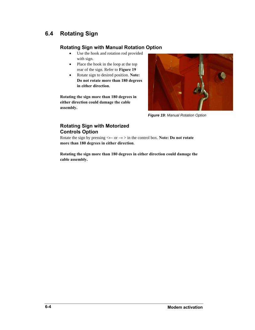


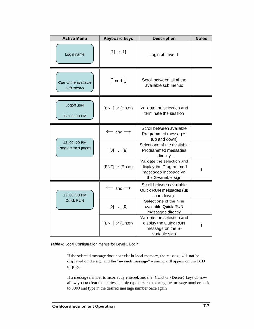


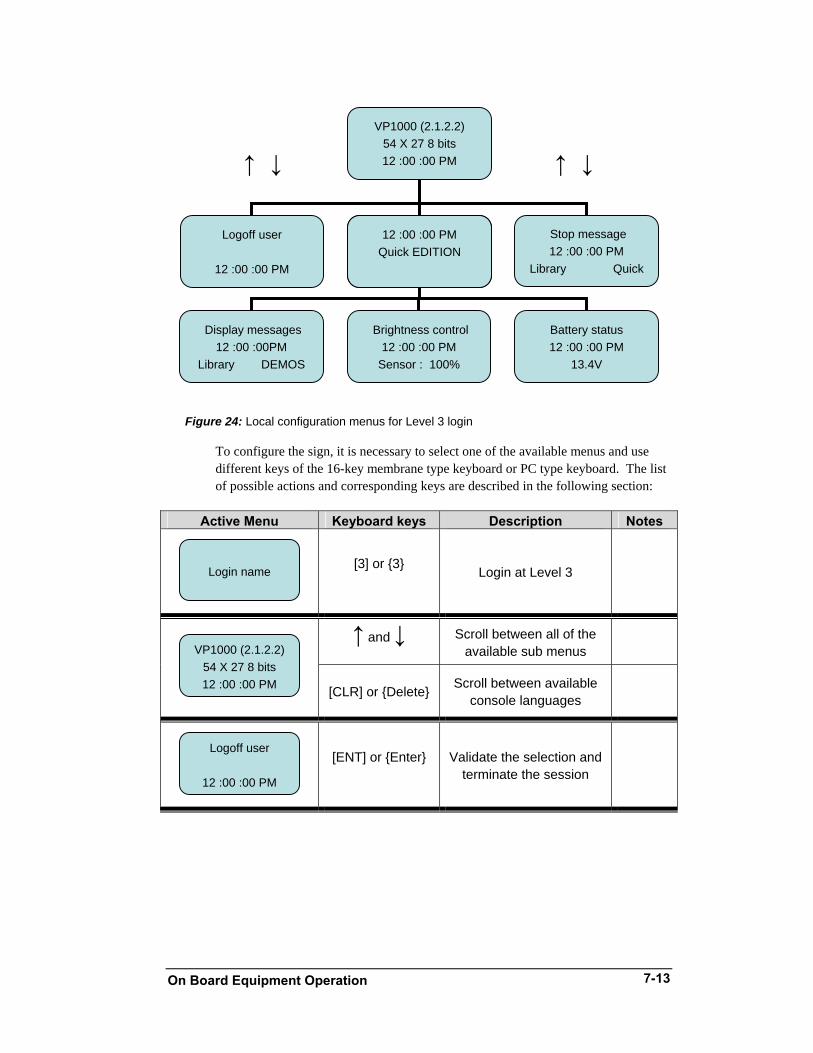


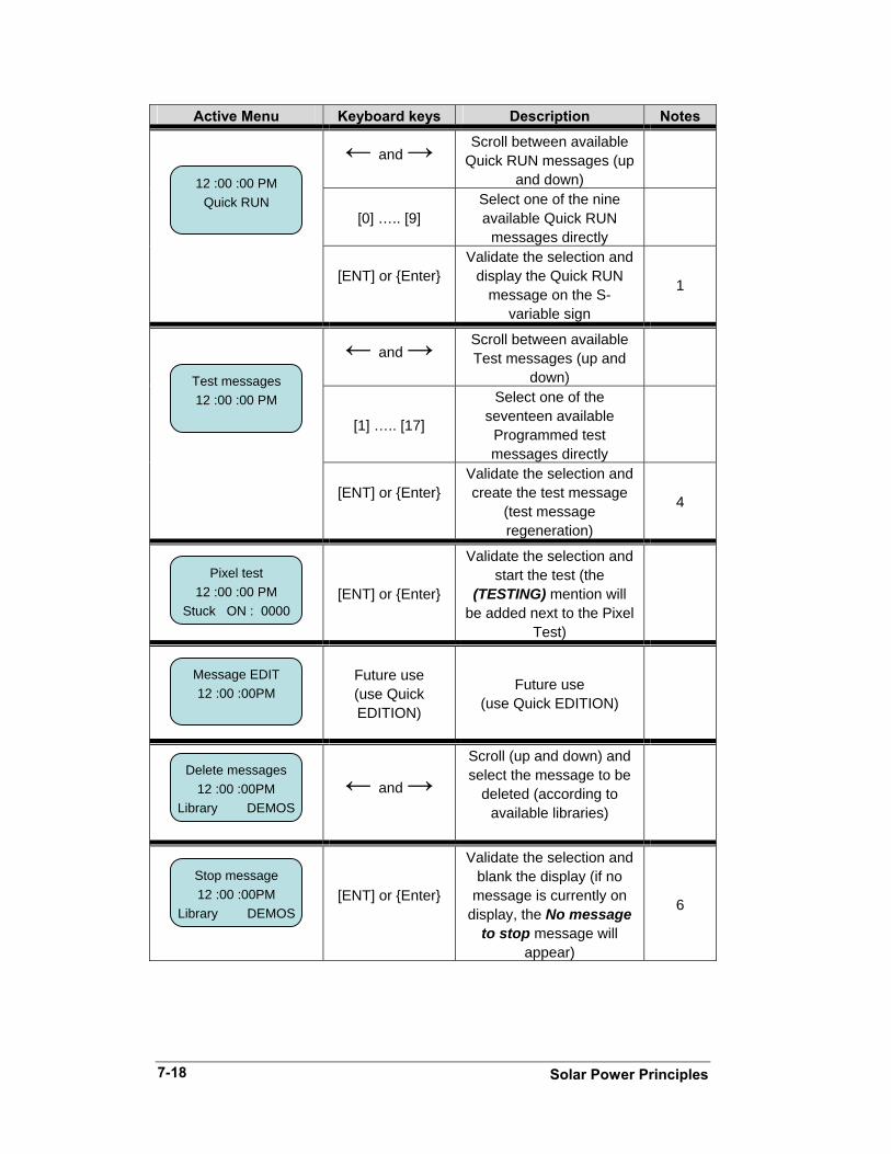
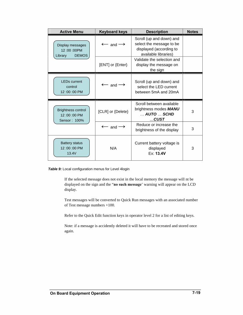


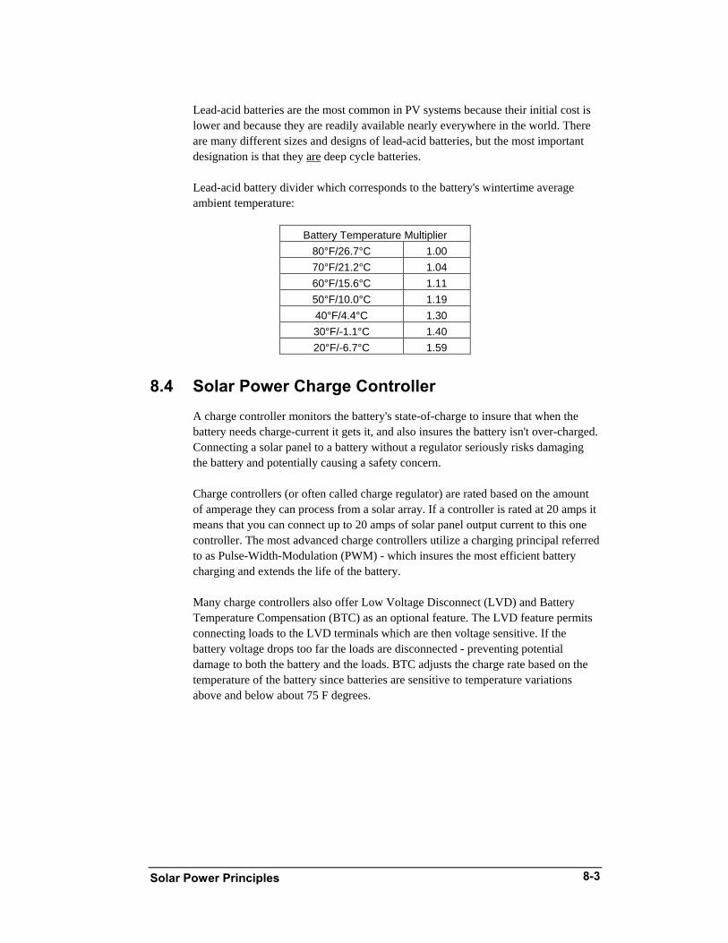


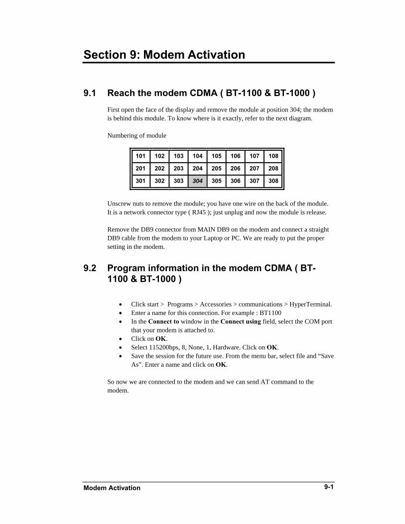

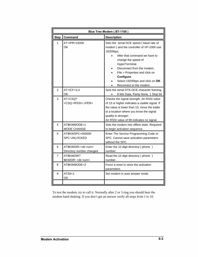


![ORTUSTECH - Display Solutions€¦ · Object substance Maximum content [ppm] Cadmium and its compound 100 Hexavalent Chromium Compound 1000 Lead & Lead compound 1000 Mercury & Mercury](https://static.documents.pub/doc/80x56/5f0f42c17e708231d44347f6/ortustech-display-solutions-object-substance-maximum-content-ppm-cadmium-and.jpg)


