1 Introduction .................................................................................................................1 1.1 Definition of terms.................................................................................................3
1.1.1 PE and CE devices ..........................................................................................3 1.1.2 Tunnels............................................................................................................4 1.1.3 Layer 2/Layer 3...............................................................................................4
2 Criteria for Assessing the Suitability of VPN Solutions .............................................6
3 CE based VPNs ...........................................................................................................8
4 PE Based VPNs.........................................................................................................10 4.1 Per-VPN Forwarding Tables................................................................................10
5 Layer 2 PE Based VPNs............................................................................................12 5.1 Types of Layer 2 VPN.........................................................................................12
5.4 LDP vs BGP.........................................................................................................18 5.4.1 Why use BGP for your VPLS? .....................................................................18 5.4.2 Why use LDP for your VPLS? .....................................................................18 5.4.3 Current Status................................................................................................19
6 Layer 3 PE Based VPNs............................................................................................22 6.1 RFC2547 VPNs ...................................................................................................22
6.1.1 Using BGP Route Reflectors to improve scalability.....................................23 6.1.2 PE-CE Communication.................................................................................23 6.1.3 Carrier’s Carrier ............................................................................................24 6.1.4 Multicast .......................................................................................................24
6.2 Virtual Routers.....................................................................................................25 6.3 Comparison of the Virtual Router architecture and RFC2547.............................26
The basic idea of a Virtual Private Network (VPN) is quite simple. A corporation may have a number of offices (or groups of offices) in different locations, and each of these locations can have its own local network. Many corporations also have an increasing number of employees working remotely – perhaps at home or on the road. Interconnecting these separate networks and locations over a shared (non-private) network creates a VPN.
Despite this apparent simplicity, there is an ever-increasing number of types of VPN available, and a bewildering range of technologies for implementing these VPNs. This makes it anything but simple to decide which VPN solution is the right one to use.
In this white paper we give an overview of the technologies currently being studied for VPN solutions. We focus mainly on VPNs where the management and maintenance is outsourced to a service provider. Our aim is to provide a guide to current and next-generation VPN technologies for service providers and network managers.
In order to do this, we first lay down some of the criteria that are important in a VPN (both from customer and service provider viewpoints). Once we have done this, we go on to examine VPN solutions and look at how well these solutions meet up to our criteria.
A VPN is a set of interconnected networks in different locations (we will refer to these separate networks as ‘sites’). Up until recently, the most common way to connect the sites has been to use ATM or Frame Relay (FR) leased lines supplied by a service provider. These leased lines have been relatively straightforward to provide, as service provider networks have traditionally been implemented using a variety of protocols including ATM and Frame Relay.
This is increasingly becoming a less than ideal solution. Leased lines are costly, and may be inflexible about the amount of bandwidth available – the customer may have to choose between a leased line with too little bandwidth or a much more expensive connection with far more bandwidth than is needed, with nothing in-between.
These leased lines are usually not the only service purchased from a provider - it is common for each of the sites to require Internet connectivity. So as well as paying for the leased line, the customer also has to pay for Internet connectivity (possibly from a different supplier) and is responsible for managing all of the routing between the different sites over the leased lines.
Another problem with VPNs that are based on leased lines is that service providers are now almost exclusively migrating to IP or IP/MPLS networks. This makes it more difficult for the service provider to offer leased lines, as the service provider has to manage an ATM or Frame Relay network as well as a separate IP backbone. This in turn makes leased lines more expensive for the customer.
As a result, there has been a substantial investment in ways to provide VPN services using an IP infrastructure within the provider's network - we refer to these as "IP VPNs". This is the common theme for all the solutions described in this white paper.
These IP VPNs reduce the cost for the customer, who no longer needs to pay for leased lines, and reduce the network management required of the service provider.
One way to create an IP VPN is for the customer simply to route data between sites using the Internet. A tunneling technology such as IPsec or L2TP is used to set up private connections between the separate customer sites, and the customer configures the equipment at each site so that data can be transmitted over these connections. This can be a good solution for small scale VPNs, with one of the advantages being that no special processing is required in the provider network. The main disadvantage to this approach is that the network management effort required to maintain the VPN quickly increases as the number of sites involved in the VPN grows. (With a full mesh topology with N sites, the number of tunnels required is of the order of N2. An alternative is a hub and spoke topology, which requires less configuration, but has a single point of failure.)
As an alternative, there are a number of new technologies that allow service providers to offer a range of different IP VPN services over their IP/MPLS network. Paying the service provider to take care of the management of the VPN saves the customer in network maintenance time, as well as offering considerable savings over using leased lines. This type of solution is also beneficial for the service provider, who can turn their network management expertise into a revenue generating service, while reducing the overhead of maintaining legacy ATM/Frame Relay equipment.
There are several different managed IP VPN solutions currently in use or under consideration and this white paper looks at some of the technology on offer. The majority of the work that goes into defining this technology takes place in the IETF – mainly in the L2VPN (Layer 2 VPN) and L3VPN (Layer 3 VPN) working groups (which previously jointly formed the PPVPN working group) and the PWE3 (Pseudo-Wire Edge to Edge Emulation) working group. We analyze some of the recent Internet drafts that have been considered by these groups.
1.1 Definition of terms Before describing the different types of VPN in any detail, we first need to introduce some of the important terminology.
1.1.1 PE and CE devices
In order to gain access to the IP backbone, there must be at least one device (such as a switch or a router) at the edge of each customer site that is connected to the service provider’s network. These are referred to as Customer Edge (CE) devices. Although these devices are logically part of the customer’s network rather than being part of the IP backbone, these devices are in some cases managed (or even owned) by the service provider.
Similarly, the device or devices (typically IP routers) that the CE devices connect to in the service provider’s network are referred to as Provider Edge (PE) devices.
The routers in the service provider network that forward data (including VPN data), but are not providing VPN functionality to a CE device are referred to as Provider (P) devices.
A simple VPN illustrating the roles of PE, P and CE devices is shown in the following diagram.
A tunnel is a means of forwarding data across a network from one node to another, as if the two nodes were directly connected. This is achieved by encapsulating the data – an extra header is added to data sent by the transmitting end of the tunnel, and the data is forwarded by intermediate nodes based on an this outer header without looking at the contents of the original packet.
This is illustrated in the diagram below, which shows data going from A to B being sent through a tunnel between X and Z. The intermediate tunnel node, node Y, does not need to be aware of the final destination, B, but just forwards the data along the tunnel to Z. (In this scenario, X is known as the ingress to the tunnel and Z as the egress.)
A X Y Z B
Send to Z
Send to B
Data
Send to Z
Send to B
Data
Send to B
Data
Send to B
Data
Tunnel from X to Z
This tunneling of data means that the P devices do not need to be aware of the VPNs, but just need to be able to forward tunneled data. This is important as it reduces the network resources consumed by the VPN and the amount of configuration required to set it up.
In addition, by sending data between VPN sites using tunnels, it is possible to maintain separation of data between different VPNs, and to prevent data from a VPN being leaked into the provider network or global internet. It also means that the addresses of devices within the VPN sites are hidden in the data transported over the tunnel, so they do not need to be changed to allow them to communicate over the Internet.
There are a number of protocols that may be used to establish these tunnels, and the properties of the tunnel have a significant effect on the overall properties of the VPN using that tunnel. However, many of the VPN solutions that we will describe do not rely on a particular tunneling technology and will work with one of several types. For this reason, we do not cover the details of the tunnels when describing the different VPN solutions (except where necessary), but instead we give an overview of the main types of VPN tunnels in chapter 7, Tunnel Technologies.
1.1.3 Layer 2/Layer 3
One major difference between types of VPN is the service that is provided to the VPN user.
For example, an IP VPN service could be a Layer 2 solution (a “Layer 2 VPN” or “L2VPN”), providing customers with the likes of Ethernet, ATM/FR Virtual Circuits (“VC”s) or leased-lines, or could be a Layer 3 solution (L3VPN), providing customers with IPv4 or IPv6 connectivity between the VPN sites.
There are advantages and disadvantages for both of these, including the following.
• Layer 2 solutions are in some ways more flexible – particularly in terms of the higher layer protocols used in the VPN. A layer 2 VPN may be transparent to higher layer protocols and so can carry IPv4 or IPv6, irrespective of the layer 3 protocol in the provider’s IP network. This also means that some of these layer 2 solutions can also carry, for example, legacy SNA, NetBios and SPX/IPX traffic. However, the most common use for a VPN is to route IP traffic between the VPN sites, and so a layer 3 VPN is suitable for most purposes.
• On the downside, some layer 2 solutions require that all the VPN sites run the same layer 2 protocol, which is not always possible.
• Layer 3 VPNs can have advantages in terms of management. For example, in a managed layer 2 VPN, the customer is still responsible for all IP routing between the customer sites, whereas in a managed layer 3 VPN, the service provider can take over this management burden.
1.2 Document Roadmap The layout of the rest of this paper is as follows.
In section 2, we lay out some criteria for assessing the suitability of VPN solutions.
We then go on to look at the solutions themselves. We break these down into several groups:
• In section 3, we look at CE-based solutions, where all of the VPN specific processing takes place in the CE devices.
• In section 4, we introduce PE-based solutions, where the VPN specific processing takes place in the PE devices. We divide these PE-based solutions further into layer 2 PE-based solutions (section 5) and layer 3 PE-based solutions (section 6).
• In section 7, we describe the properties of various types of tunnels that are used for VPNs.
• Section 8 contains a summary of how each of the VPN solutions we have examined matches up to the criteria laid out in section 2.
• Section 9 includes further technical details about some of the solutions described earlier in the document.
• Section 11 contain a glossary of some of the important terms used in this paper. References are listed in section 12.
2 Criteria for Assessing the Suitability of VPN Solutions
There are many different VPN technologies to choose from, and network operators need to put together a list of their requirements and pick a solution that meets these requirements. For a VPN user, such a list will typically include the following criteria.
• VPN Service. The VPN service must match the type of service required by the VPN user. Different VPN solutions offer either layer 2 or layer 3 connectivity between VPN sites. As described in section 1.1.3, this choice will depend on the type of traffic that will be sent between customer sites, as well as the layer 2 and layer 3 protocols in use at each individual site.
• Quality of Service. The VPN user may require a certain quality of service (QoS) for the connections between VPN sites (for example, the VPN user may require a minimum guaranteed bandwidth). If this is the case, the service provider backbone must support the provisioning of QoS-constrained tunnels, and the VPN solution must be able to make use of these tunnels.
• Security. If sensitive data is to be sent across the backbone between VPN sites, then the solution should support encryption, authentication and integrity checking of data in the VPN tunnels. In addition, it is a further advantage if the routing information distributed in the provider network is also protected, to prevent the VPN network topology from being exposed to prying eyes.
• Capital Cost (to the VPN user). The VPN user may require a solution that does not involve a costly replacement of their existing hardware. Therefore, any VPN solution offered by a service provider must not require expensive extra function to be added to the customer edge devices. Ideally, the solution will be fully interworkable with the VPN user’s existing switches and routers.
• Manageability. The VPN user will want a solution that is simple to manage and which minimizes the migration costs. The configuration of the VPN solution should not be so complex that the network management personnel require extensive training. Neither should the solution require a significant overhaul of the VPN user’s existing network architecture. Equally, the ongoing day-to-day management should not be too onerous – for example, it should be easy to add new sites to the VPN.
• Maturity. The VPN user will want a solution that has widespread industry acceptance and deployment. Less mature solutions carry the risk that the technology may not yet be thoroughly tested, and the architectural and interoperability issues entirely overcome. There is also the danger that they may not be offered by an acceptable range of providers, limiting the VPN user’s range of choice and ability to source alternative back-up solutions. At the same time, many vendors and providers may be looking to differentiate their product or service offering by driving the establishment and deployment of new solutions.
All of these criteria have focused primarily on the needs of the VPN user. However, a service provider also has some extra requirements for a VPN solution, as follows.
• Capital Cost (to the SP). The amount of money that needs to be spent on new equipment must be kept to a minimum. A solution will not be suitable if an SP has to upgrade every router in their network in order to deploy it!
• Scalability. The solution must scale well. This has two separate meanings. Firstly, the amount of manual configuration required should not become unmanageable as more VPNs are supported by the SP. Secondly, the amount of extra system resources taken up on each router as VPNs are added to the backbone must be small enough not to require costly hardware upgrades or slow the routers down significantly.
• Additional Services. Ideally, the SP would like to be able to use the VPN offering to allow it to make a range of value-added services to the VPN user. This would offer the SP the chance to increase revenue from their customers.
A number of different IP VPN solutions are discussed below and, for each, we make reference to these criteria and assess their advantages and drawbacks.
To start off with, we examine VPN solutions where all the VPN specific processing takes place in the CE devices – we will refer to these as “CE-based” solutions.
In some ways, this is the simplest type of IP VPN, as the provider network does not take part in any of the layer 2 or layer 3 routing of VPN traffic, and so the PE devices can be standard IP routers. This is one of the big advantages of this type of solution for the service provider. Unlike the PE-based VPNs we will look at, the PE devices do not need to store any MAC addresses or IP addresses internal to the VPN, and do not need to get involved in the internal routing of the VPN. This means that the solution scales well in the provider network.
CE-based VPNs are grounded in the traditional VPNs based on Frame Relay and ATM leased lines. Leased lines create a VPN by providing point-to-point connectivity between sites. Similarly, one can create an IP VPN by setting up IP-based tunnels between CE devices.
The properties of a VPN created in this way (particularly quality of service, the type of traffic carried and security) are inherited from the type of tunnel technology used. For example, IPsec tunnels provide a secure way of tunneling IP traffic for a layer 3 VPN, while L2TP provides a means for transporting layer 2 traffic for a layer 2 VPN. Any of the types of tunnel described in section 7 can be used, and the properties of standard tunnels are discussed later.
In terms of the criteria we laid down in section 2, one of the problems with CE-based VPNs is the amount of management and configuration required for the CE-devices. This configuration can become quite complex, particularly if the VPN involves a large number of sites. In addition, the VPN user may need to purchase new equipment to carry out the tunneling and/or routing required to maintain the VPN. One way for the VPN user to reduce this management complexity is to have the service provider manage (and possibly even supply) the CE devices.
There are a couple of Internet drafts describing how the provider can manage the CE devices remotely. These describe ways in which configuration information can be transmitted by the service provider to the CE-devices for layer 2 VPNs (see draft-lee-ce-based-vpl), and layer 3 VPNs (draft-ietf-ppvpn-ce-based).
If a CE-based VPN grows to include a large number of sites, the management required by the service provider to maintain the mesh of tunnels becomes more and more difficult. A solution for this is given by draft-lee-ppvpn-ce-auto-config, which provides a means for automatically configuring the CE-devices in this type of VPN.
Having looked at CE-based VPNs, we now move on to PE-based VPNs, where the majority of the VPN configuration and management takes place in the service provider’s VPN edge devices. We will further subdivide this group of solutions into layer 2 and layer 3 solutions (see sections 5 and 6 respectively).
Note that PE-based VPNs automatically tend to match up well with the customer-oriented criteria we put forward in section 2. In particular, the fact that the PE devices perform most of the VPN specific processing usually means that the CE devices can be standard switches or routers and therefore there is not usually a need to upgrade equipment on the customer premises. Also, since the service provider is responsible for management of the VPN, there is usually little work required of the customer. On the other hand, these properties mean that there is more management required of the service provider, and it is more likely that the provider will need to upgrade equipment to support this type of solution.
4.1 Per-VPN Forwarding Tables We need to introduce an additional concept that is relevant to PE-based VPNs – that of separate forwarding tables. This is illustrated by the following diagram, which shows several CE and PE devices taking part in two separate VPNs. Separate tunnels through the provider network are shown for each VPN.
In all of the layer 3 PE-based VPN solutions, it is necessary for the PE device to route IP packets from sites that belong to several different customers and are members of several VPNs. The PE device may need to route packets from one locally connected site to another, or from one CE device to a remote PE device, which in turn will route the packets to another CE device in the same VPN. (For example, in the diagram above, when PE 1 receives packets from VPN 2, site 1 that are destined for VPN 2, site 2, it needs to forward them over the tunnel to PE 2.)
This is made more complicated by the fact that VPNs are private networks, and so may legitimately use the same (or overlapping) address spaces. For example, in the diagram above, it is perfectly possible for a host in VPN 1, site 7 to have the same IP address as a host in VPN 2, site 1. This same IP address could also be used in the Internet or in the provider’s network.
Hence each PE router requires several separate forwarding tables – in particular, it needs a Virtual Routing and Forwarding table (VRF) for each VPN.1
There is a similar issue for PE-based layer 2 VPNs. Although in this case data is forwarded by the PE device based on layer 2 information rather than destination IP address, the layer 2 forwarding tables are still typically stored on a per-VPN basis.
1 Although having one VRF per VPN is the most common case, this is not the only possibility, as a site may belong to more than one VPN. For example, a PE connected to a single CE device that belongs to VPN 1 and VPN 2 would only need 1 VRF. On the other hand, PE 3 in the example above is involved in 2 VPNs but has 3 VRFs – one for routes from VPN 1, another for routes from VPN 2, and another for routes from VPN 1 and 2.
5.1 Types of Layer 2 VPN There are three main types of layer 2 VPN. Each provides a different type of service to the customer. This chapter describes the main types of layer 2 VPN and goes on to describe some of the solutions for implementing these types of VPN together with details of their current state of industry acceptance and deployment.
5.1.1 VPWS Overview
The first type of layer 2 VPN we will look at provides point-to-point connectivity between customer sites. This type of VPN is known as a Virtual Private Wire Service (VPWS) and the service provider network can be thought of as emulating a set of wires between the customer sites.
This is particularly useful in the case where a customer is currently using a set of ATM or Frame Relay connections between the different customer sites, as existing links between the customer and provider can be used. The customer can keep the same layer 2 connections to the service provider, but instead of data being carried natively over an ATM or Frame Relay service, the traffic is encapsulated and routed over the provider’s IP backbone This clearly minimizes the migration cost to the customer. It also means that this option is particularly appropriate to migrating specific existing networks – such as those based on a hub-and-spoke architecture which requires a number of branch offices to have connectivity to a single main office or data-center.
The following diagram shows the point-to-point layer 2 connections between the customer sites, illustrating a section of each connection being emulated by the provider network.
IP backboneCustomer
Site
CustomerSite
CustomerSite
Layer 2Access Circuits
Layer 2 connections emulated bythe service provider's IP network
Another type of layer 2 VPN is a Virtual Private LAN Service (VPLS). In this type of VPN, the Ethernet LAN at each customer site is extended as far as the edge of the provider network. The provider network then emulates the function of a LAN switch or bridge to connect all of the customer LANs to create a single bridged (Ethernet) LAN.
One of the main differences between a VPWS and the VPLS described above is that the VPWS only provides a point-to-point service, whereas the VPLS provides a point-to-multipoint service. This also means that the requirements on the CE devices are quite different. In a VPWS, layer 2 switching must be carried out by the CE routers, which have to choose which Virtual Wire to use to send data to another customer site. In comparison, the CE routers in a VPLS simply send all traffic destined for other sites to the PE router.
SP network acts as a virtual LAN bridge
SP networkCustomer
Site
CustomerSite
CustomerSite
5.1.3 IPLS Overview
In many networks, only IP traffic needs to be exchanged between customer sites, and the customer edge device is an IP router, instead of a layer 2 switch. If this is the case, then it is possible to use a third type of layer 2 VPN – an IPLS (which stands for IP-only LAN-like Service, IP over LAN Service or IP LAN Service, depending on which Internet draft you read.). As this type of VPN only forwards IP traffic, it is easy to confuse an IPLS with a layer 3 VPN – however, as traffic is forwarded based on the layer 2 header information, the IPLS still falls into the layer 2 VPN category.
5.2 VPWS Solutions In this section, we consider four VPWS solutions. Each gives the customer a VPWS that looks like a traditional layer 2 VPN made up by connecting the customer sites using ATM or Frame Relay leased lines. In each case, this is done by emulating a set of point-to-point wires between the CE routers. The main differences between the solutions lie in the amount of configuration required by the service provider, and the types of tunnels used through the provider network.
One thing to note is that with any VPWS (unlike a VPLS or IPLS), it is necessary for the end-points of the virtual private wires to be configured on the CE-devices, which must be capable of switching data on to the correct wire. In terms of the criteria laid out in section 2, this means that a VPWS will generally require greater ongoing management effort from the VPN user than a VPLS or IPLS.
5.2.1 MPLS-based VPWS
One of the simplest ways to create a VPWS is to use ATM or Frame Relay VCs between the PE devices and CE devices, and to cross-connect each of these to separate MPLS circuits (Label Switched Paths or LSPs) through the provider network, as illustrated in the diagram below. Note that LSPs are uni-directional, and so two LSPs are required for each bi-directional connection.
CE1 PE1
CE3
PE2
PE3
CE2
VCs between the PEand CE
LSPs between PEdevices
This is a relatively straightforward approach, and MPLS traffic engineering can be used to provide quality of service if this is required by the customer. However, when used for multiple VPNs, it does not scale well in the provider network for the following reasons.
• Firstly, each LSP through the provider network needs to be configured individually and then cross-connected to the specified VC at each end, which requires considerable management effort from the service provider.
• Secondly, a large number of LSPs may be needed in the provider network, which uses large (and, compared with later solutions, wasteful) amounts of resource in the service provider’s routers.
5.2.2 PWE3 VPWS
An improvement on this approach is to use the PWE3 extensions to MPLS that are currently being standardized by the IETF in the PWE3 working group.
These extensions improve scalability by using a fixed number of MPLS LSPs between PE devices in the provider network. Emulated, point-to-point layer 2 connections (known as pseudo-wires or Martini pseudo-wires, after the author of the original draft) are then created between pairs of PE devices by tunneling through such an LSP.
The signaling for these pseudo-wires is defined in draft-ietf-pwe3-control-protocol. The encapsulation required for forwarding data across these pseudo-wires is defined for several layer 2 protocols, including ATM, Frame Relay and Ethernet (draft-ietf-pwe3-atm-encap, draft-ietf-pwe3-frame-relay and draft-ietf-pwe3-ethernet-encap).
Therefore, an alternative to the MPLS based VPNs described above is to cross-connect layer 2 PE-CE connections with pseudo-wires using the appropriate layer 2 encapsulation. Since each pseudo-wire only consumes resources in the PE devices, this is an improvement on the method described in 5.2.1, which also requires additional state in intermediate P devices.
Although this reduces the amount of resource consumed in the provider routers, this approach still requires too much management effort to create large scale VPNs, because each pseudo-wire needs to be configured individually. However, there are other, more scalable ways to use pseudo-wires to create layer 2 VPNs, as we shall see in section 5.3.
5.2.3 Kompella L2VPN
A more scalable VPWS solution is described in draft-kompella-ppvpn-l2vpn. This draft gives a mechanism for creating a VPWS using BGP as both an auto-discovery protocol and a signalling protocol.
In this solution, each PE devices uses Multi-Protocol BGP (MPBGP) to advertise the CE devices and VPNs connected to it, together with the MPLS labels used to route data to them. Consequently, when this information is received by the other CE devices, they learn how to setup the VPWS.
For more technical details about how a Kompella L2VPN is set up see section 10.1.
One of the important features of this solution is that the configuration and management required in the provider network is much simpler than that for leased lines or the MPLS and Martini solutions mentioned above – this makes it cheaper for the provider to supply such a service.
In addition, this type of VPWS is more flexible than using leased lines. With leased lines, the connections between the customer and the service provider need to use the same layer 2 protocol. However, with Kompella L2VPNs, there are cases where it is possible to use different layer 2 protocols at different sites when the data passed between customer sites is in the form of IP traffic. The mechanisms for this are described in draft-kompella-ppvpn-l2vpn, with some additional details given in draft-shah-ppvpn-arp-mediation.
We should also compare the Kompella L2VPN solution against the MPLS-based and PWE3 solutions described in 14 and 5.2.2. In terms of scalability, it is a significant improvement on the MPLS-based solution. Like a PWE3 VPWS, new point-to-point connections are created through the provider network by tunneling over an existing set of LSPs, thereby avoiding additional occupancy in the P devices. In terms of configuration, the Kompella approach is much better, because the provider only needs to configure the PE device with information about the local VCs and CE identifiers. The PE devices automatically learn (using BGP) which other PE devices are involved in the VPWS and so can set up the required tunnels.
The previous sections have focused on VPWS solutions where access to the provider’s network uses traditional layer 2 technology such as Ethernet or ATM. Solutions also exist for a more general transport mechanism between CE and PE, such as optical fibers or SONET/SDH.
One such solution is described in draft-ouldbrahim-ppvpn-gvpn-bgpgmpls. This is a very similar solution to MPLS L2VPNs described in section 5.2.1, but the links from CE to PE can consist of any transport layer, and GMPLS (as described in RFC 3471 and related documents) is used as the PE-PE and CE-PE signaling protocol. (This solution also suggests using BGP as an auto-discovery protocol, to ensure that all PE devices know which VPNs they should be taking part in. This is very similar to the auto-discovery mechanisms discussed in the following sections on VPLS.)
5.3 VPLS Solutions There are currently two key VPLS solutions being pursued by equipment vendors, and being progressed by the IETF L2VPN working group. The two approaches are described in draft-ietf-l2vpn-vpls-ldp and draft-ietf-l2vpn-vpls-bgp and are detailed more fully below.
Both solutions deliver very similar functionality, and describe how to set up a VPLS over a service provider network supporting MPLS. However, the working group has been unable to reach consensus on the superior approach. Instead, they have chosen to progress both solutions to the status of “Proposed Standard”, and to let the market decide which will prosper. In a couple of years time, when more deployment experience has been attained, the working group then plans to move one (or both) solution to the status of “Draft Standard”.
As can be seen from the controversy, VPLS is a fairly new technology, although deployment is proceeding quickly. To give an indication of the speed of update, over 20 providers worldwide announced commercial VPLS services during the first quarter of 2004. This contrasts wth only two providers announcing commercial VPLS services during 2003.
The rest of this section
• compares and contrasts the two competing VPLS solutions
• looks at the scalability of a VPLS offering
• discusses Hierarchical VPLS – an extension to the architecture which can ameliorate some of the performance limitations.
This VPLS solution is based on pseudo-wires set up using draft-ietf-pwe3-control-protocol, as described in section 5.2.2. Whereas the PWE3 drafts describe how Layer 2 data can be transported in a point-to-point fashion between two PE routers in the provider network, draft-ietf-l2vpn-vpls-ldp describes how to take a collection of these pseudo-wires and combine these into a point-to-multipoint layer 2 VPN. The basic idea is that a full mesh of pseudo-wires is set up between the PE devices that are participating in a specific VPLS. These PE devices then carry out packet replication and MAC address learning similar to that performed in a standard Ethernet switch in order to forward frames correctly from one CE to another. The following diagram illustrates a VPLS constructed using pseudo-wires to connect the modules in the PE devices responsible for performing MAC address learning etc.
Per-VPNMAC learning
module
PE
PEPer-VPN
MAC learningmodule
PEPer-VPN
MAC learningmodule
CE
CE
CE
Martini pseudo-wires
In order to simplify the configuration of the VPLS for the provider, help is at hand in the form of auto-discovery mechanisms. When a PE device first starts to participate in a particular VPLS, it can automatically learn of the other PE devices and set up the pseudo-wires without any additional management effort. Several auto-discovery mechanisms are possible, and three options are described in draft-ietf-l2vpn-radius-pe-discovery, draft-ietf-ppvpn-bgpvpn-auto and draft-stokes-ppvpn-vpls-discover. These use the RADIUS, BGP and LDP protocols respectively for discovery, with BGP being the most popular option. Without auto-discovery, the configuration of the pseudo-wires could become a complicated management task, particularly if the VPLS involves a large number of sites.
5.3.2 Competing VPLS solutions: BGP VPLS
The LDP VPLS solution described in 5.3.1 can be achieved in an almost identical fashion by using BGP as the label distribution protocol, rather than LDP. This is described in draft-ietf-l2vpn-vpls-bgp.
In this solution, MAC learning is still performed by the PE devices, and pseudo-wire setup is accomplished by BGP signaling, as opposed to LDP. Importantly, because BGP is being used to distribute labels, it makes sense to use BGP as the auto-discovery protocol.
5.4 LDP vs BGP So why are there two competing VPLS solutions? Here we attempt to spell out the arguments offered by each side for using either option.
5.4.1 Why use BGP for your VPLS?
• BGP is already suggested by both solutions as an auto-discovery protocol. Given BGP is already running on a device, why introduce a second protocol if BGP can do the job? (An additional protocol increases processing and occupancy overheads, as well as bandwidth usage).
• Configuration and management of a single protocol is easier than configuration and management of several protocols.
• Using BGP to distribute labels is familiar to service providers who have already successfully implemented 2547-based solutions (see section 6.1 for more details on these).
5.4.2 Why use LDP for your VPLS?
• Many devices will already be running LDP to set up MPLS tunnels over which the VPLS solution is run. Therefore, it is a logical to use LDP to distribute VPLS labels as well.
• LDP requires fewer protocol extensions to be able to distribute VPN labels (after all, it is a Label Distribution Protocol). Extending BGP as described in draft-ietf-l2vpn-vpls-bgp loads a well-defined protocol with extra function, which has two downsides.
• Vendors with existing BGP implementations will extend those solutions. Such implementations, whilst often less expensive than those built from scratch, are typically less stable and more prone to bugs than purpose-built implementations.
• Fatal protocol errors (that can cause session shutdown, or even a protocol stack restart) can potentially disable more function. For example, in the LDP VPLS model, if a BGP session (or indeed, the entire BGP stack) goes down, all that is lost is auto-discovery – labels that have been distributed to peers by LDP are still valid.
Most vendors seem to have taken the LDP road so far (including Cisco), but one major vendor (Juniper) has gone down the BGP road. Neither side appears to have an argument strong enough to win on a purely technical basis, so the two approaches are likely to co-exist for some time. The sheer weight of implementations using LDP might push the industry towards consolidation at some future stage, but that seems a long way off!
5.5 VPLS Scalability Whichever flavor of VPLS is deployed, there are some scalability limitations that apply equally.
• VPLS places a significant burden in the PE devices. In particular, the PE device performs routing in the provider network, it maintains the MPLS tunnels in the provider network together with the pseudo-wires on top of these, and it performs MAC learning for all of the attached VPLSs. This means that the PE device will need enough processing power and memory to maintain the forwarding state for hundreds or thousands of VPLS instances, each of which could have thousands of MAC addresses. Obviously, a service provider planning to offer VPLS services will need to make a trade off between the size and number of VPLS instances supported and the cost of the PE device (or distributed PE devices) required.
• The size of a single VPN instance is limited by the efficiency of the MAC learning and bridging algorithms deployed. As a general rule of thumb, it is likely to be possible to connect tens of sites to a single VPLS VPN, but not hundreds.
5.6 Hierarchical VPLS As noted above, VPLS requires a full mesh of pseudo-wires between all PE devices. However, service providers often place small edge devices in multi-tenant buildings (called Multi-Tenant Units, or MTUs) and aggregate several of them into a larger PE device in a Central Office (CO) facility. It is not practical to treat every MTU as a fully-fledged PE device, since each would require a pseudo-wire to every other MTU in the service providers network for each VPLS, and this might be beyond the capacity of a small device.
To solve this problem, rather than treating every MTU as a PE, it is beneficial to only set up the mesh of tunnels between the primary PEs in the COs, and refer to these pseudo-wires as “hub” pseudo-wires. Each MTU then maintains separate pseudo-wires to its attached PE device(s), known as “spoke” pseudo-wires.
Such an arrangement is known as Hierarchical VPLS (H-VPLS), and is shown in the following diagram. The MTU device is often referred to as a U-PE (user-facing PE), with the core PE as an N-PE (network-facing PE).
MTU /U-PE
MTU /U-PE
N-PE-1
N-PE-2
N-PE-3
CE-1
CE-2
CE-3
The advantages of this approach are as follows.
• Data between CE-1 and CE-2 can be routed directly without the PE router being involved.
• The numbers of PEs between which a full mesh of tunnels needs to be set up is reduced.
• An MTU can be “dual-homed” to two PE devices to protect from connection failure.
H-VPLS is described in detail in draft-ietf-l2vpn-vpls-ldp. This approach seems to be well established as a good solution to the core LSP scalability issue.
However, H-VPLS does not solve the problem of the N-PE devices needing to maintain a very large number of MAC addresses. Ideally, this MAC address learning function could be distributed down to the U-PE devices as well.
One method for doing this is proposed in draft-kompella-ppvpn-dtls. DTLS (also referred to as Decoupled VPLS) extends the Kompella VPWS solution described in section 5.2.3 and turns it into a distributed VPLS solution, where MAC learning now becomes a function of the U-PE device.
Other ideas on solving the MAC address problem can be found in draft-radoaca-l2vpn-gvpls, although there are no implementations based solely on this draft.
As yet, there is very limited deployment experience of any of the hierarchical VPLS solutions.
5.7 IPLS Solutions The study of IP-over-LAN Services is still at a relatively early stage. The solution currently being studied by the PPVPN working group is draft-ietf-l2vpn-ipls, which describes how to create an Ethernet IPLS.
An IPLS has the restriction that all of the CE devices are IP routers and all the VPN traffic is IP traffic. In this case, all of the traffic passing from one site to another is in the form of IP packets, and the next hop for each IP packet is another CE device. This means that the only MAC addresses that the PE devices need to know about when forwarding the layer 2 frames are those of the CE devices.
For more details about how an IPLS is set up, see section 10.2.
Notwithstanding (and even because of) the restrictions of an IPLS compared to a VPLS (most notably that only IP traffic can be transported), this solution has a number of advantages over the VPLS solutions described above - in particular, ease of configuration and scalability.
There is little configuration required for an IPLS, as the PE device automatically learns about locally attached CE devices and other PE devices.
The scalability advantage over VPLS comes from the reduced number of MAC addresses that need to be stored. Whereas in the VPLS case the PE devices need to maintain a forwarding information base by MAC learning (which could involve a large number of MAC addresses from the customer sites), the PE devices in the IPLS only need to maintain the IP addresses and MAC addresses of the CE devices. This will mean that more sites can be connected to a single IPLS VPN than a VPLS VPN. However, it is worth bearing in mind that a IPLS VPN cannot be extended indefinitely. In particular, a customer is likely to need to run a fully meshed IGP protocol (such as OSPF) over the VPN – and this will have its own scalability limitations.
In practice, this will mean that the limit on the number of sites that can be satisfactorily connected to an IPLS VPN will be in the hundreds (as opposed to tens for a VPLS VPN).
The work being carried out by the L3VPN working group in the IETF is further advanced than the work of the L2VPN working group. This means that the protocols are more stable, and so it is likely to be easier for a service provider to purchase equipment that supports these layer 3 VPNs, and also likely that routers from different suppliers will interoperate successfully.
From the VPN user’s perspective, both of the solutions we look at below are quite similar. Any data that the user wants to send to a remote site is forwarded to a PE device, which then takes care of the complexities of inter-site routing. Also, the CE devices do not need any special VPN specific function in either case, and so the user is not likely to need any costly equipment upgrades. As we shall see, the main differences lie in the details of the processing in the provider network.
It is also important to note that since this solution is based on IP protocols, it is easiest for a provider to offer additional services to a VPN user alongside a Layer 3 VPN. These solutions could include IP telephony, server hosting and unified messaging.
6.1 RFC2547 VPNs The BGP/MPLS VPN solution, originally described in RFC2547 (and currently being updated in draft-ietf-l3vpn-rfc2547bis) is the most important of the layer 3 VPN solutions. This is the most commonly used form of service provider managed VPN at present, with over 200 providers advertising commercial RFC2547 based solutions at the time of writing.
The basic version of this type of VPN transports IPv4 VPN traffic across a provider network using MPLS tunnels. There are several variations on this: draft-ietf-l3vpn-ipsec-2547 and draft-ietf-l3vpn-gre-ip-2547 use different types of tunnels (IPsec and GRE respectively), and draft-ietf-l3vpn-bgp-ipv6 describes how to transport IPv6 VPN traffic across the (possibly IPv4) provider network.
Since it is common for service providers to use BGP as a routing protocol in their backbone networks, this is a logical protocol to use to distribute routes from attached VPN sites. The routes from each VPN site are either configured in the PE device, or advertised to the PE device using a routing protocol such as BGP or OSPF. The PE device advertises the routes to remote PE devices using BGP, which then advertise them to attached CE devices in the same VPN. The PE devices then establish a mesh of tunnels between all devices connected to the same VPN or VPNs to carry the traffic.
Further details about the operation of an RFC 2547 VPN can be found in section 10.3.
6.1.1 Using BGP Route Reflectors to improve scalability
It is not necessary for the BGP instances on all the PEs to communicate directly with each other in a mesh topology. Instead, an RFC2547 VPN can take advantage of BGP Route Reflectors (described as an extension to BGP in RFC 2796) to improve scalability. draft-ietf-l3vpn-rfc2547bis describes how this can be achieved.
However, when Route Reflectors are in use, the number of routes they need to maintain can potentially be very large, leading to scalability problems. So a scheme that uses “Cooperative Route Filtering” is also described in the draft, in an attempt to limit the amount of routing information held by the Route Reflectors. Some limitations of this scheme have been pointed out, and are addressed in draft-ietf-l3vpn-rt-constrain.
6.1.2 PE-CE Communication
One differentiator between the service offerings of those providers with RFC 2547 based Layer 3 VPNs is the choice of protocol used for transferring routes from CE to PE and back. There are a number of possibilities here, and the selection of protocol is important for a number of reasons.
• Each provider typically only offers one or two choices of PE/CE protocol.
• Each choice will require different levels of expertise from the operations staff of the VPN user.
• The choice may impact the routing and addressing used within the VPN user’s internal network. In extremis, the customer may need to change the IGP that they have deployed internally, and accept the risk that the provider is able to feed routes directly into the VPN user’s corporate network.
The potential choice of protocol for PE to CE communication, along with comments on each are as follows.
• Static configuration. This is clearly the simplest, requiring relatively little expertise from the VPN user. However, it is also the least flexible and dynamic.
• BGP, particularly E-BGP (External BGP). This is a popular choice of protocol, since it can be configured to offer strong safeguards against route pollution in either direction. However, it will either also require (rare) BGP expertise from the VPN User, or require the provider to manage some or all of the CE themselves.
• OSPF (as described in draft-ietf-l3vpn-ospf-2547). This might be a good choice if the VPN User is already running OSPF as an IGP, since it will build upon existing experience. However, it does open the VPN User’s network up to more risk from misconfiguration from the Provider.
• EIGRP. This is a Cisco proprietary IGP. This would be a good choice if both VPN User and Provider are using Cisco equipment and have experience of this protocol. However, it has the disadvantage that it locks in the use of equipment from a single vendor.
• RIP (Routing Information Protocol), as specified in RFC 2435, and ISIS (as described in draft-sheng-isis-bgp-mpls-vpn). Although both these protocols have been suggested as for use in PE/CE communications, there has been relatively little actual deployment of either to-date.
6.1.3 Carrier’s Carrier
A VPN might actually be the network of a service provider, providing its own VPN services to its own customers. Thus one service provider uses the network of another as if it were a standard customer of that “inner” service provider. The “inner” service provider is known as the Carriers’ Carrier.
The mechanism to support this is very similar to that described above, except that the CE devices of the outer service provider must support MPLS. The CE devices connecting to the inner network (which are of course the outer service provider’s routers), use BGP to distribute internal routes to the inner network, and LDP (or any other label distribution protocol) to distribute labels to the inner network, and receive them from it. This prevents the inner service provider PEs from needing to examine the actual destination of traffic on the outer carrier’s customers’ VPNs – it can switch on the label instead. Carrier’s Carrier is described in draft-ietf-l3vpn-rfc2547bis, and is illustrated in the following diagram.
Customer Site 1
CE1R1PE3CE3
Inner ServiceProvider Network
PE2PE1 P
tunnel
Customer Site 2
CE2 R2 PE4 CE4
6.1.4 Multicast
So far, we have only considered 2547 support for unicast routing. What happens when a multicast routing protocol, such as PIM (Protocol Independent Multicast), is in use within the VPN?
For optimal multicast routing, when a PE receives a multicast packet from a CE, the packet must be sent to those other PEs which have sites connected to them with nodes listening for for the packet’s multicast group. This means that the packet must not be sent to any other PEs (ie those without relevant multicast receivers attached), nor must it be unnecessarily replicated. This requires a source-tree for the multicast group, which would mean that the service provider’s core routers (not just the PEs) would have to maintain state for each transmitter of each multicast group in each VPN.
While this would provide optimal multicast routing, it would also require an unbounded amount of state in the core routers, since the service provider has no control of the number of multicast groups in the VPNs that it supports, nor does it have any control over the number of transmitters or receivers in each group.
draft-rosen-vpn-mcast addresses this problem for the specific case of PIM being the multicast routing protocol.
To date multicast routing protocols have not yet in been wide use across corporate networks, so there is little immediate requirement for efficient VPN multicast solutions. However, with the growth of technologies such as IP telephony, video on demand, corporate communications and distance learning, multicast routing is rapidly becoming more significant. Accordingly, this is an area where VPN support is expected to progress rapidly in the near future.
6.2 Virtual Routers Another layer 3 VPN solution is the Virtual Router (VR) architecture. The idea is that each PE router runs a number of ‘virtual routers’ – one corresponding to each VPN forwarding table. Each virtual router consists of one or more routing protocol instances associated with a forwarding table, just like a normal router. In order to get connectivity between a virtual router in one PE device and another virtual router for the same VPN in another PE device, it is necessary to set up tunnels across the provider network. The virtual routers can then exchange routing information using any standard routing protocol.
This is subtly different from the RFC2547 solution. In both cases, there is effectively a virtual router corresponding to each VRF that forwards data to and from the CE devices. In the RFC 2547 case, a single instance of BGP is used to advertise the routes from all VRFs throughout the provider network. In the VR case, routes are advertised through in the provider network using a separate routing protocol instance for each VRF.
The following diagram shows two VR-based VPNs, and illustrates the use of multiple tunnels between the PE devices. It is useful to compare this with the comparable diagram for a RFC 2547 based VPN (which can be found at the end of section 10.3).
PE devicePE device
VRF
VRF
CE
CE
CE
VRF
VRF
CE
CE
BGP BGPTunnel
OSPF OSPF
Tunnel
One aspect of this architecture is that each PE router taking part in a VPN needs to have tunnels set up to all the other PE routers in the same VPN. While this mesh of tunnels could be set up manually, this could be quite a complicated task in a large VPN. However, draft-ietf-l3vpn-bgpvpn-auto suggests a way to use BGP to distribute information about membership of a Virtual Router VPN, which would allow the PE routers to automatically set up the required tunnels.
6.3 Comparison of the Virtual Router architecture and RFC2547 The virtual router solution appears to be lagging far behind the RFC2547 type solutions in terms of popularity with equipment vendors and service providers.
The main reasons for this are management and scalability. In RFC2547, a single mesh of tunnels is required between the PE routers. In the virtual router architecture, it is necessary to maintain a separate overlay of tunnels for each VPN – although these tunnels may be set up using the auto-configuration draft suggested above, scalability is still a cause for concern. Also, the configuration effort required for all of the routing instances needed to set up a number of VPNs based on the virtual router architecture can become prohibitive.
The main advantage of the virtual router architecture over the RFC2547 solutions is that the VPN routes are kept completely separate from the routing in the provider network. Although routes are stored in separate forwarding tables in the RFC2547 approach, the routes are still passed between PE routers using the same instance of BGP that exchanges Internet routes in the provider network. This means that any problems with BGP sessions caused by the VPN routes can potentially affect normal Internet connectivity. However, drafts are currently being developed to address this limitation (draft-ietf-idr-bgp-multisession-00.txt)
As we have seen, tunnels are used in all of the VPN solutions that we have looked at, and so these are an important part of any managed VPN. Tunnels based on different technologies can have quite different properties, which in turn can have a significant effect on the resulting VPN.
7.1 Tunnel Properties The main properties of tunnels we will consider are security and scalability.
A VPN customer whose data is being tunneled across a public network will want to know if that data is secure. The CEO may get upset if private documents can be read on their way to another part of the corporate VPN! So it is worth bearing in mind that the security of the tunnel is important for maintaining the privacy of VPN data - if the tunnel is not secure, it may be necessary for the customer to encrypt any sensitive data that is sent over the VPN.
The main issue with scalability is in the number of tunnels that may be required across the provider backbone, and the amount of network resource that the tunnels consume. In particular, it is a major advantage if the tunneling protocol allows multiplexing – in other words, if multiple data streams can be forwarded over the tunnel and then separated at the tunnel endpoint without requiring extra state in intermediate devices. When multiplexing is possible, the provider network need only maintain a single mesh of tunnels between PE routers, which can be used by all VPNs. If multiplexing is not possible, then a separate mesh of tunnels is required for each VPN.
The following diagram shows two data streams being multiplexed through a single tunnel.
7.2 Tunnel Protocols The main tunneling protocols that are used for VPNs are MPLS, IPsec, IP-in-IP, L2TP, and GRE. A brief translation of each acronym is given below!
7.2.1 MPLS
Multi-Protocol Label Switching is a technology being standardized by the IETF, which provides high-speed data forwarding and bandwidth reservation.
The underlying principle is that packets are forwarded through an MPLS tunnel by switching on attached labels, without looking at the contents of the IP header. The tunnel ingress node adds a label to the packet, and subsequent nodes forward based on the incoming interface and label, sending the packet on to the next node with a new label value. The last node in the MPLS tunnel removes the label before forwarding the packet to its final destination. The path followed by the data is known as a Label Switched Path (LSP).
One of the benefits of MPLS is that it is possible to set up LSPs inside LSPs (inside LSPs…!), which gives very good multiplexing properties. Tunneling one LSP through another is simply a matter of adding another label to the “label stack” (the collection of labels attached to the packet). As the packet progresses, it is switched using the outer label. At the end of the LSP, the outer label is popped off, and the packet is switched using the new outer label.
Another advantage of MPLS as a VPN tunnel technology is that MPLS traffic engineering can dedicate resources to an LSP. This is good for a customer with a VPN based on MPLS, who can be sure of having a set amount of bandwidth. This gives the service provider an opportunity to offer extra value to the customer, which can in turn put a smile on the face of the service provider’s accountant.
The only thing that the customer needs to worry about then is security. However, an analysis of the security of VPNs using MPLS tunnels (draft-behringer-mpls-security) has shown that security is similar to that which would be provided if the VPN sites were connected using ATM/Frame Relay virtual connections. In particular, data is kept private - as with ATM and Frame Relay, network problems may cause packet loss, but are unlikely to result in packets being delivered to the wrong destination. On the other hand, it is still a sensible precaution to encrypt any particularly sensitive data.
For a more in-depth account of MPLS as a VPN tunneling protocol, see the Data Connection white paper “MPLS Virtual Private Networks”.
Another tunneling protocol that is very popular for building VPNs is tunnel mode IPsec, which has several desirable features. Since IPsec has been developed for security reasons, it is not surprising that it has everything on the security shopping list - connectionless integrity, data origin authentication, anti-replay and encryption. (Note though that there is a performance hit in the forwarding plane from using encryption.)
Another benefit of IPsec is that it is connectionless - an IPsec tunnel between PE devices does not consume any resources in the P routers. The only state required is some shared security information (a “Security Association”) between the PE devices, which can be manually configured or distributed automatically (e.g. using IKE).
On the negative side though, there is no natural demultiplexer for IPsec tunnels, although it is possible to get around this deficiency - for example, by running MPLS over an IPsec tunnel. This and other options are explored in draft-duffy-ppvpn-ipsec-vlink.
Even without looking at the tunneling applications, IPsec can be useful in any VPN. Whatever type of VPN you use, if you are sending sensitive IP traffic between sites, you might want to secure it from prying eyes by using transport mode IPsec over the underlying transport.
7.2.3 L2TP
L2TPv3 (Layer 2 Tunneling Protocol version 3) is a protocol designed for tunneling layer 2 information across a layer 3 network. As such, it is not surprising that the protocol is particularly useful for layer 2 VPNs.
Happily for the VPN provider, scalability is good – tunnels only consume resources at the tunnel endpoints, and the tunnels can be multiplexed. Although L2TP does not have any built in security, L2TP can be run over transport mode IPsec, providing a healthy level of security for the layer 2 VPN.
7.2.4 IP-in-IP
RFC2003 describes a mechanism for tunneling IP packets over IP. Although the scalability of this is good in one sense – no tunnel setup is required, and no state needs to be maintained – the main problem is that multiplexing is not possible, and so a different IP address is needed for each tunnel endpoint. The lack of spare IPv4 addresses, together with the lack of security makes IP-in-IP less than ideal for VPN use.
7.2.5 GRE
The Generic Routing Encapsulation (GRE) protocol was originally defined in RFC1701, but was later updated in RFC2784 with less function. To put it simply, GRE allows you to tunnel any protocol inside any protocol.
The main use of GRE in the VPN context is to carry IP in IP. As with RFC2003, this has the advantages that there is no need to signal any connection, and no resources are consumed by the GRE tunnel.
So far, this is very similar to the properties of RFC2003 IP-in-IP. However, there is a key difference. The extensions to GRE described in RFC2890 allow multiplexing of GRE tunnels. This allows us to set up tunnel data from multiple VPNs using GRE without needing to deplete the stock of remaining unused IP addresses.
7.2.6 Summary
The following table shows the main properties of the different tunnel types. The features of the tunnels that are considered are:
• Do the tunnels have the scalability advantage of a multiplexing capability?
• How secure are the tunnels?
• Can traffic engineering can be applied to the tunnels to provide QoS for the VPN?
• Do the tunnels require stored state, and if so, which nodes need to store state?
Multiplexed Security Traffic Engineered
Stored State
MPLS Y Equivalent to ATM/FR.
Y All tunnel nodes, for the bottom tunnel. End points only for nested tunnels.
Ipsec N Good N Endpoints only IP-in-IP N None N None L2TP Y None N Endpoints only GRE Y None N None
We have looked at the operation of various VPN technologies and have compared these against the criteria we laid out in section 2. This comparison is summarized below.
CE-based
PE-based layer 2 PE-based layer 3
Kompella VPWS
VPLS IPLS RFC 2547 bis
Virtual Router
What traffic types are supported?
Layer 2/Layer 3
ATM/FR Ethernet IP over Ethernet
IPv4 or IPv6
Is traffic engineering available through the provider network?
No Yes, if MPLS tunnels are used
Is the tunneled data secure? See the table in section 7.2.6. Do the CE devices need to be VPN capable?
Yes No No No No No
Is VPN specific configuration of the CE devices required.
Yes Some No No No No
Do the PE devices need to be VPN capable?
No Yes Yes Yes Yes Yes
How does the solution scale for PE devices?
N.A Well Not well unless distributed
Well Well Not well
How does the solution scale for sites in a VPN?
N/A Poorly 10s of sites feasible
100s of sites feasible
Well 100s of sites feasible
How mature is the solution?
Mature Mature Immature but growing
Immature Mature Immature
What is the migration and ongoing management cost to the VPN user?
High ongoing cost
Low migration cost, ongoing burden
Low Low Potentially high migration cost, low ongoing burden
Is a significant amount of management required from the provider?
No, except for SP managed solutions
Yes, but auto-configuration options are available in each case.
How easy is it for the provider to deploy value-added services?
Data Connection Limited (DCL) is the leading independent developer and supplier of (G)MPLS, OSPF(-TE), ISIS(-TE), BGP, VPN, RIP, PIM, IGMP, MLD, ATM, MGCP, Megaco, SCTP, SIP, VoIP Conferencing, Messaging, Directory and SNA portable products. Customers include Alcatel, Cabletron, Cisco, Fujitsu, Hewlett-Packard, Hitachi, IBM Corp., Microsoft, Nortel, SGI and Sun.
DCL is headquartered in London UK, with US offices in Reston, VA and Alameda, CA. It was founded in 1981 and is privately held. During each of the past 21 years its profits have exceeded 20% of revenue. Last year, sales exceeded $36 million, of which 95% were outside the UK, mostly in the US. Even through the current severe downturn, Data Connection’s financial position remains secure, as does its employee base: our 200 software engineers have an average length of service of 8 years, with turnover of <3% annually.
Our routing protocols are designed from the ground up to address next generation networking issues such as massive Internet scalability, optical routing at multiple layers, virtual routing, MPLS and TE/CSPF, and VPNs.
DC-MPLS, DC-VPN Manager, DC-BGP, DC-OSPF, DC-ISIS and DC-LMP provide a complete set of solutions for optical and packet control plane requirements. These include integrated VPN solutions for BGP/MPLS VPNs and Martini.
All of the Data Connection protocol implementations are built with scalability, distribution across multiple processors and fault tolerance architected in from the beginning. We have developed extremely consistent development processes that result in on-time delivery of highly robust and efficient software. This is backed up by an exceptionally responsive and expert support service, staffed by engineers with direct experience in developing the protocol solutions.
Data Connection is a trademark of Data Connection Limited and Data Connection Corporation. All other trademarks and registered trademarks are the property of their respective owners.
This section provides more technical details about some of the VPN solutions described earlier in this document. It is provided to aid readers wishing to understand the technology behind the VPNs.
10.1 Kompella L2VPNs The mechanism used for setting up a VPWS based on the Kompella draft is as follows.
The first step is to allocate identifiers for each of the CE devices. These identifiers must be unique within the VPWS. The diagram below shows a VPWS with CE devices 1, 2 and 3.
PE1CE1VC 2,3
Local labels advertised by BGP:L12 maps to VC2L13 maps to VC3
Remote labels learnt by BGP:L21: Used to send data from VC2 to CE2L23:UnusedL31: Used to send data from VC3 to CE3L32: Unused.
PE3
CE3
Local labels advertised by BGP:L31 maps to VC1L32 maps to VC2
Remote labels learnt by BGP:L12:UnusedL13: Used to send data from VC1 to CE1L21: UnusedL23: Used to send data from VC2 to CE2
Remote labels learnt by BGP:L12:Used to send data from VC1 to CE1L13: UnusedL31: UnusedL32: Used to send data from VC3 to CE3
PE2
CE2
Local labels advertised by BGP:L21 maps to VC1L23 maps to VC3
VC2
VC1
L12
VC 1,3
VC 1,2
The next step is to set up the connections (typically ATM or Frame Relay Virtual Circuits) between the CE devices and the PE devices. Each CE is configured with a separate VC for each remote CE device that it wishes to connect to. These VCs are typically chosen so that there is a simple algorithm mapping from the remote CE identifier to the identifier of the VC to use.
In parallel to this, the service provider must set up tunnels between the PE routers (see section 7). The tunneling protocol used is not too important, although MPLS is the ideal choice - as we shall see, MPLS labels are used to identify the virtual circuits. A full mesh of tunnels is not required – tunnels between PE devices are only needed where connectivity is required between the attached CE devices.
Now, a PE device receiving VPWS data from another PE device needs to be able to identify which VC to use in order to get the data to the CE device. To achieve this, the PE router allocates a block of MPLS labels for each CE – the block contains one label for each VC that connects the PE and CE routers. In the diagram above, we use the notation Lxy to denote the label allocated corresponding to VC y of CE x. For example, PE 1 allocates label L12 and label L13 corresponding to CE 1. Data received from another PE router with label L12 is sent over VC 2 and data received with label L13 is sent over VC 3.
Once a PE device has allocated its set of labels, it has to tell other PE devices (a) that it is involved in the VPWS, and (b) which labels to use when sending data from their attached CE devices. This is achieved by using Multi-Protocol BGP (MPBGP or MBGP) to advertise the block of labels, together with a VPWS identifier (which is sent as a BGP Route Target extended community).
When a PE device receives a label block associated with a particular remote CE device, it associates the block with the correct VPWS using the VPWS identifier. This PE then uses the CE identifiers of locally attached CE devices to identify which labels in the label block it will need to use. Roughly speaking, the CE identifier of any connected CE device gives the offset in the label block of the correct label to use when forwarding data from that CE device to the CE device associated with the label block.
In our example, when PE 2 receives the label block from PE 1, it knows that the labels have been allocated for sending data to CE 1. There is one label for each remote CE to send data to CE 1, and so there are two labels, one for use for data from CE 2 and one for data from CE 3. The first label in the block is for use for data from CE 2, and the second label is for use for data from CE 3. As PE 2 is only connected to CE 2, it can ignore the second label and only uses the first label.
As shown by the dashed line in the diagram above, CE 2 can now send data to CE 1. To do so, it simply sends the data over VC 1, which is the VC corresponding to CE 1. PE 2 knows that data received on VC 1 should be tunneled to PE 1, with label L12 (the label for data from CE 2 to CE 1). When PE 1 receives data with the label L12, the label is removed and the data is forwarded over VC 2 to CE 1.
10.2 IPLS The mechanism used for setting up an IPLS is as follows.
The first step is for a PE device to learn about the locally attached CE devices. It does this automatically, by snooping IP and ARP frames, enabling it to find out both the MAC addresses and IP addresses of the local CE devices. The PE device can automatically learn about other PE devices in the same IPLS – it can do this using the same BGP auto-discovery methods as for a VPLS (e.g. draft-ietf-ppvpn-bgpvpn-auto).
For each locally connected CE device, a PE sets up a new Martini pseudo-wire to each remote PE device involved in the IPLS. When data is received on this pseudo-wire, the PE can forward it straight on to that CE without any need for an address lookup. When a pseudo-wire is signaled to another PE, the IP address and MAC address of the CE are included, and are stored by the remote PE device. This allows each PE device to build up a table of all the IP and MAC addresses of the CE devices in the IPLS. This table is used to perform proxy ARP, which in turn lets the CE devices learn the MAC addresses of remote CEs.
Once the IPLS is set up, IP packets are routed from one site to another as follows.
• The data source encapsulates the IP packet as a MAC frame and forwards it to the local CE device.
• The CE device decapsulates the IP packet and performs IP routing to find the next hop IP address.
• The next hop IP address is resolved to the MAC address of the remote CE device (using the proxy ARP function supplied by the PE device).
• The CE device then re-encapsulates the IP packet as a MAC frame with the remote CE device as the destination, and sends the frame to the PE device.
• The PE device uses the destination MAC address (which is that of the remote CE device) to look up the correct Martini pseudo-wire, and sends the frame.
• The receiving PE device knows which pseudo-wire the frame was received over, and so knows which CE device to send the data to.
• This CE receives the MAC frame, decapsulates it and routes the IP packet as normal.
The above discussion only describes the forwarding of unicast data. A slightly different mechanism is used for multicast data. In addition to the per-CE unicast pseudo-wires, the PE devices set up a full mesh of pseudo-wires for multicast traffic. So when a PE receives a multicast frame from a CE, it broadcasts it over the multicast pseudo-wires to all the other PEs, which in turn broadcast the data to all the attached CEs (regardless of which CEs need the multicast data).
The following diagram illustrates the pseudo-wires set up by a PE in an IPLS. Only the pseudo-wires set up by PE 1 are shown – for each remote PE, there is one pseudo-wire for receiving data for each local CE, and there is also a separate pseudo-wire for transmitting multicast data received from the local CEs.
PE 1VPN Site 1
CE 2
PE 2 VPN site 2CE 3
PE 3 VPN site 2CE 4
CE 1
Pseudo-wire for multicast data from CE 1 or CE 2
Pseudo-wire for unicast data for CE 1Pseudo-wire for unicast data for CE 2
10.3 RFC 2547 L3VPNs As noted earlier in this document, an RFC 2547 Layer 3 VPN is established using BGP to distribute the VPN routes.
The routes from each VPN site are either configured in the PE device, or advertised to the PE device using a routing protocol such as BGP or OSPF. The PE device advertises the routes to remote PE devices using BGP, which then advertise them to attached CE devices in the same VPN.
However, this is not as straightforward as it may at first seem, because the VPN address spaces may overlap, and BGP will only store one route for each address prefix. For example, if a PE router receives 172.19.11/24 from VPN 1, this needs to be treated differently from 172.19.11/24 from VPN 2, (or 172.19.11/24 from the global Internet).
The trick is to make these identical addresses different, by extending BGP. A new BGP address family is defined for VPN routes, and addresses in this VPN-IPv4 family consist of a Route Distinguisher (RD) plus an IPv4 prefix.
This is illustrated in the diagram below, which shows two different VPNs advertising the same IPv4 prefix to PE 1. By adding different Route Distinguishers (RD X and RD Y), BGP on PE 1 advertises two different VPN-IPv4 prefixes to PE 2.
The Route Distinguisher is a way to make the VPN addresses unique, but does not give any information about the route, such as identifying the VPN. Instead, the VPN to which the route belongs is carried in a separate BGP attribute – a Route Target Extended Community. This allows a PE router receiving a VPN-IPv4 route to install the route in the correct forwarding table.
As we hinted at earlier, the RFC2547-based solutions require that a full mesh of tunnels (MPLS, IPsec or GRE) be set up between the PE devices. Using a separate set of tunnels for each VPN would be inefficient, so a single mesh of tunnels is shared between all the attached VPNs. This means that a PE device receiving data over one of these tunnels needs to identify the VPN associated with the data. It cannot simply use the destination IP address, due to the overlapping address spaces. The solution is to associate an MPLS label with each route, and to use BGP to advertise this label to the other PE devices along with the route. When a PE device forwards data for one of these routes, this label is attached to the IP packet, and this label tells the PE device receiving the data (i.e. the PE device that advertised the label) how to forward it.
Note that the labels used in this way are not necessarily unique to a particular route – it may actually identify the VRF, or may be associated with the interface to the CE device that advertised the route. In the former case, when the PE router receives data with a label corresponding to a particular VRF, it has to look up the destination prefix in the VRF before it can forward the data to the appropriate CE device. This is slightly less efficient than the latter case, in which the data can be forwarded without any routing table look-up.
To summarize the flow of data from one CE to another in this type of VPN:
• The CE forwards a packet to the PE.
• The PE looks up the route in the VPN forwarding table and adds an MPLS label.
• The packet is forwarded over the tunnel to the remote PE device.
• The remote PE device receives the packet and looks at the MPLS label.
• This PE uses the MPLS label to forward the packet to the CE, possibly by looking up the destination address in the VRF.
In a sense, this MPLS label creates an MPLS LSP inside the tunnel between the PE routers, with this inner LSP extending as far as the per-VPN forwarding tables. The following diagram illustrates two RFC2547 VPNs, with two inner LPSs shown in different colors.
PE devicePE device
VRF
VRF
CE
CE
CE
VRF
VRF
CE
CE
BGP BGP
Tunnel
One worry that customers may have with a VPN is that the provider may accidentally make a mistake with the VPN configuration. Having a competitor’s customer site join your network is likely to be viewed as a bad thing! Although it is difficult to prevent configuration errors, it is some comfort if you can spot this type of error, and draft-ietf-ppvpn-l3vpn-auth offers a means for CE devices in layer 3 VPNs to check that the other CE devices in the same VPN are allowed to be there.
This section provides a brief review of some of the VPN related terminology used in the document. For an extensive list of terminology, see draft-ietf-l3vpn-ppvpn-terminology.
Access circuit the circuits connecting the CE to the PE in a layer 2 VPN.
CE device Customer Edge device. A device in the customer network that interfaces with the equipment in the service provider’s network that supplies the VPN services.
GRE, IP-in-IP, IPsec, L2TP, MPLS in the context of VPNs, these are all tunneling technologies. See chapter 7, Tunnel Technologies.
IPLS IP-over LAN Service. See section 5.1, Types of Layer 2 VPN.
LSP Label Switched Path. The path along which MPLS data is forwarded between two MPLS-enabled routers.
MTU Multi-Tenanted Unit. A device that is remote from a provider’s PE, but provides PE-like service to several CEs.
N-PE Network facing PE.
PE device Provider Edge device. A device (such as a router) in the provider’s network that interfaces with the customer’s VPN equipment.
PPVPN Provider Provisioned Virtual Private Network. A VPN for which the management and maintenance is outsourced to a service provider.
Pseudo-wire an emulated (point-to-point) layer 2 connection over a provider’s IP network.
U-PE User-facing PE.
VPLS Virtual Private LAN Service. See section 5.1, Types of Layer 2 VPN.
VPN Virtual Private Network. Network created by linking geographically separate LANs.
VPWS Virtual Private Wire Service. See section 5.1, Types of Layer 2 VPN.
VRF Virtual Routing and Forwarding table. See section 4.1.
draft-kompella-ppvpn-l2vpn Layer 2 VPNs Over Tunnels draft-shah-ppvpn-arp-mediation ARP Mediation for IP Interworking of Layer 2
VPN draft-ietf-l2vpn-vpls-ldp Virtual Private LAN Services over MPLS draft-ietf-l2vpn-l2-framework Framework for Layer 2 Virtual Private Networks
(L2VPNs)
draft-ietf-l2vpn-requirements Service Requirements for Layer 2 Virtual Private Network Services (L2VPN)
draft-ietf-pwe3-control-protocol Transport of Layer 2 Frames Over MPLS draft-ietf-pwe3-ethernet-encap Encapsulation Methods for Transport of Ethernet
Frames Over IP and MPLS Networks draft-ietf-pwe3-frame-relay Frame Relay over Pseudo-Wires draft-ietf-pwe3-atm-encap Encapsulation Methods for Transport of ATM
Cells/Frame Over IP and MPLS Networks draft-ietf-l2vpn-ipls IP-Only LAN Service (IPLS) draft-ouldbrahim-l2vpn-lpe VPLS/LPE L2VPNs: Virtual Private LAN
Services using Logical PE Architecture draft-radoaca-ppvpn-gvpls GVPLS/LPE draft-kompella-ppvpn-dtls Decoupled Virtual Private LAN Services
draft-ietf-l3vpn-rfc2547bis BGP/MPLS VPNs draft-ietf-l3vpn-ipsec-2547 Use of PE-PE IPsec in RFC2547 VPNs draft-ietf-ppvpn-as2547 Applicability Statement for VPNs Based
on rfc2547bis draft-ietf-l3vpn-bgpvpn-auto Using BGP as an Auto-Discovery
Mechanism for Layer-3 and Layer-2 VPNs
draft-ietf-l3vpn-requirements Service requirements for Layer 3 Provider Provisioned Virtual Private Networks
draft-ietf-l3vpn-framework A Framework for Layer 3 Provider Provisioned Virtual Private Networks
draft-ietf-l3vpn-rt-constrain Constrained VPN route distribution draft-ietf-l3vpn-gre-ip-2547 Use of PE-PE GRE or IP in RFC2547
VPNs draft-ietf-l3vpn-bgp-ipv6-vpn BGP-MPLS VPN extension for IPv6
VPN draft-ietf-l3vpn-mpls-vpn-mib MPLS BGP L3VPN MIB draft-ietf-l3vpn-vpn-vr Network based IP VPN Architecture
using Virtual Routers draft-ietf-l3vpn-as-vr Applicability Statement for Virtual
RFC 3031 MPLS Architecture RFC 2401 Security Architecture for the Internet
Protocol draft-duffy-ppvpn-ipsec-vlink Framework for IPsec Protected Virtual
Links for PPVPNs RFC 2003 IP Encapsulation within IP RFC 2784 Generic Routing Encapsulation (GRE) RFC 2890 Key and Sequence Number Extensions to
GRE draft-ietf-l2tpext-l2tp-base Layer Two Tunneling Protocol (Version
3) "L2TPv3"
12.6 Data Connection White Papers Data Connection has published various other White Papers, including “MPLS Virtual Private Networks”, which looks at the use of MPLS as a tunneling protocol for VPNs. These can be downloaded from our website, at http://www.dataconnection.com.


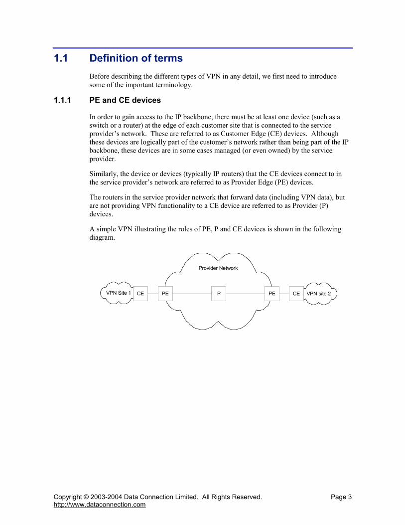


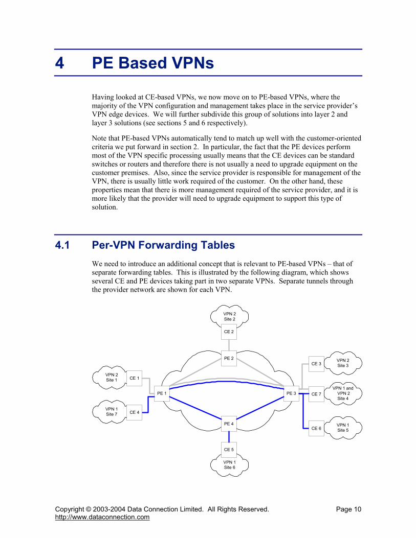
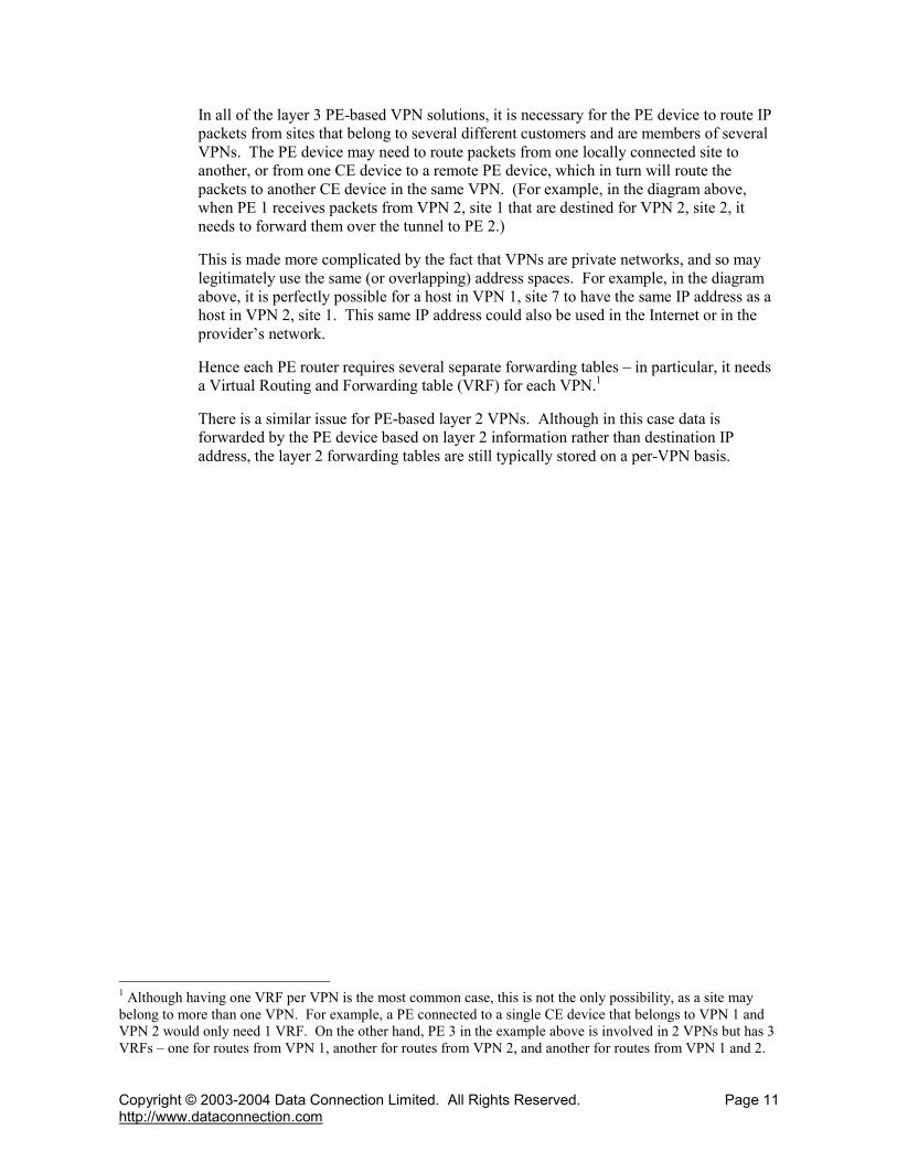
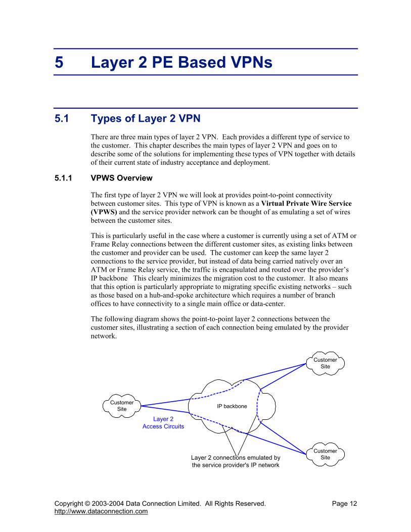
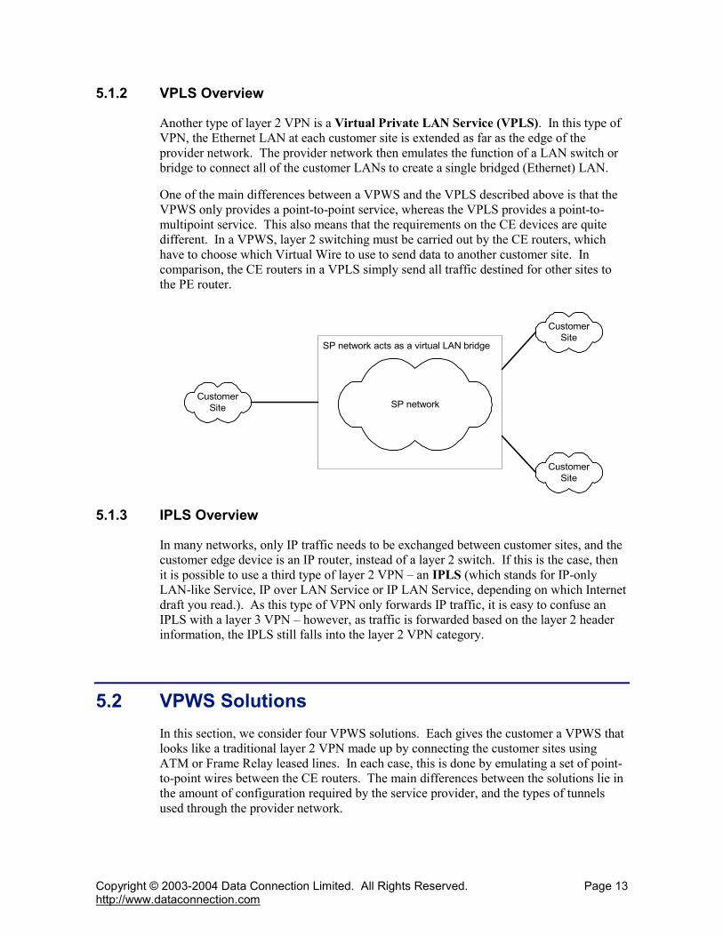

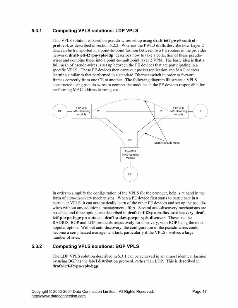
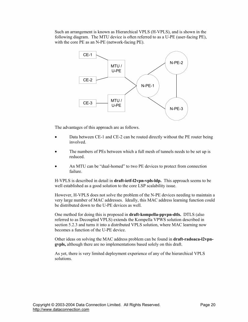


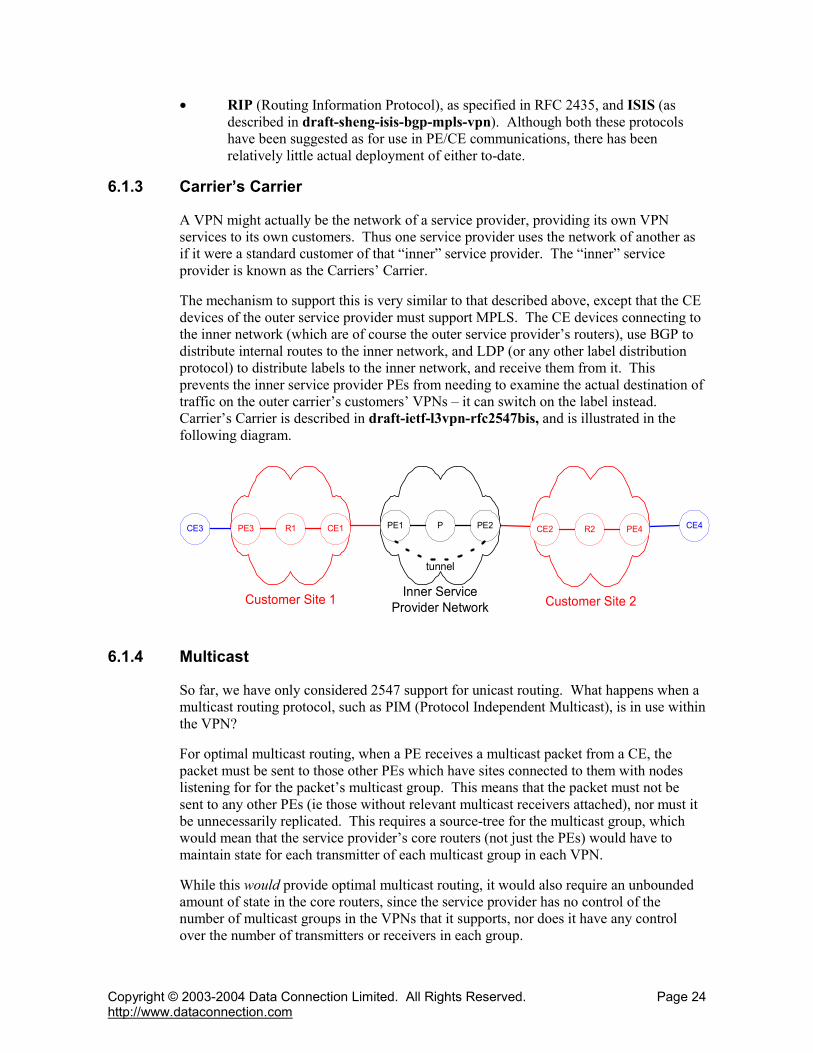

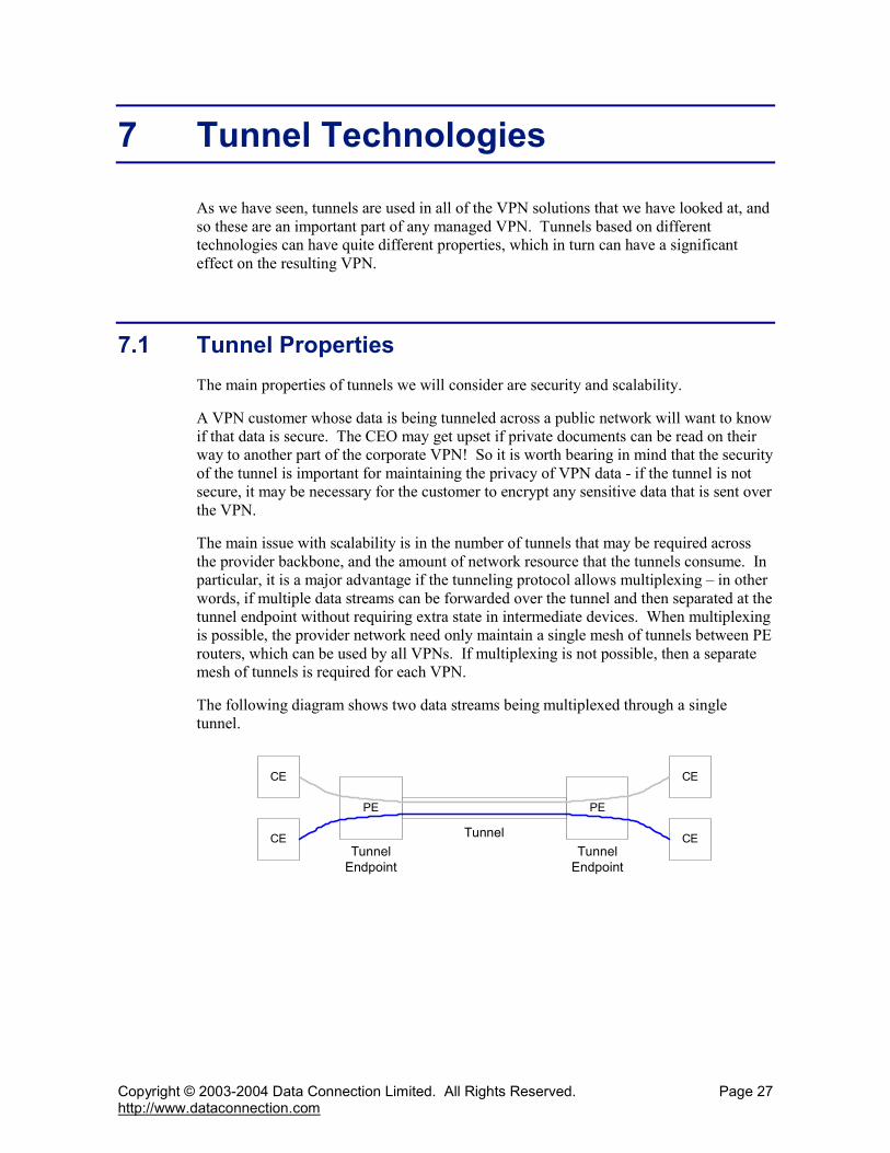
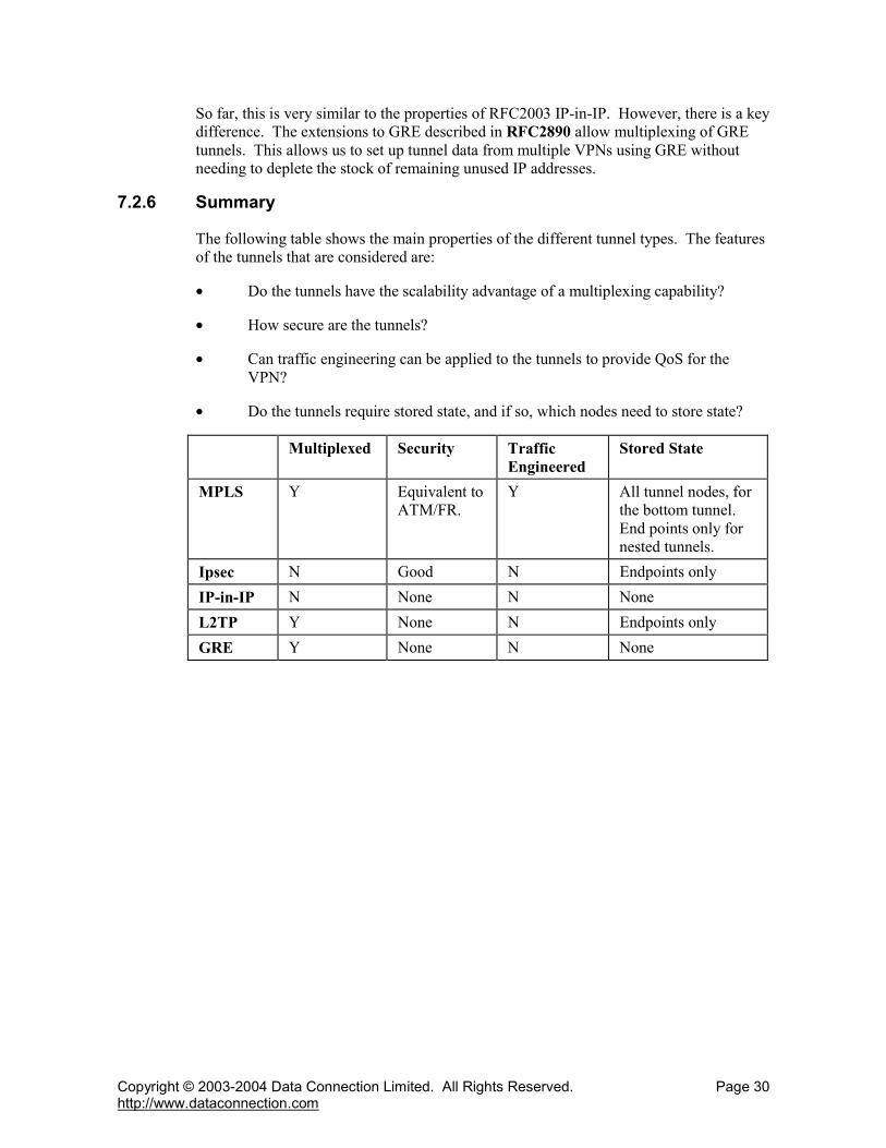
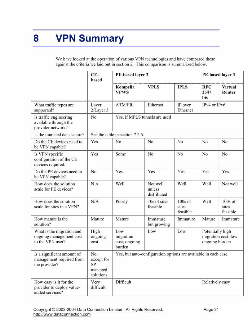


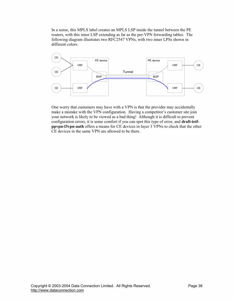


![03 Deploying MPLS L3VPN - start [APNIC TRAINING WIKI] · 9/27/16 4 Cisco,Public IP/VPN Technology MPLS IP/VPN Topology,/,Connection, Model 7 PE)) MPLSNetwork MP2iBGPSession PE P P](https://static.documents.pub/doc/80x56/5e6e23e9c995644485343013/03-deploying-mpls-l3vpn-start-apnic-training-wiki-92716-4-ciscopublic-ipvpn.jpg)


