Joint Service/Navy-Wide Systems Architectures and Standards FORCEnet is the core of Sea Power 21 and naval transformation, and is the Navy and Marine Corps vehicle to make Network- Centric Operations/Warfare (NCO/W) an operational reality. FORCEnet is the “glue” that makes Sea Strike, Sea Shield, and Sea Basing possible by integrating weapons, sensors, command/con- trol, platforms, and warriors into a secure, networked, distributed combat force as part of the Global Information Grid. FORCEnet is not an acquisition program; it is an enterprise alignment and integration initiative that serves as a change agent and a forcing function for innovation, touching every naval program. Since its inception in 2003, FORCEnet has substantially transformed the Navy and Marine Corps in both process and product. FORCEnet is being implemented in coordination with transformation initia- tives in the Army, Air Force, and Coast Guard—enhancing efficiency, joint interoperability, and warfighting effectiveness. FORCEnet is key to the Navy’s strategic shift from a platform- centric to a NCO/W environment. This includes how the Navy defines future capabilities-based requirements, develops systems, and delivers combat power to the warfighter. NCO/W derives power from rapid, robust, and secure networking of well- informed, geographically dispersed warfighters that will enable an overpowering tempo and a precise, agile style of maneuver warfare. Using effects-based operations, the aim is to sustain access and decisively impact events ashore. FORCEnet develops and drives command and control doctrine and processes to make commanders at all levels more effective by enhancing efficient use of information, allowing accelerated and improved decision- making. Toward this goal, the FORCEnet Functional Concept was developed jointly by Navy and Marine Corps warfighters and operators, and was approved by the Chief of Naval Operations and the Commandant of the Marine Corps in 2005. Additionally, enhanced joint warfighting capabilities, including the development and refinement of warfighting requirements and operational processes, were fielded in both 2003 and 2004 through the Trident Warrior joint operational event. Trident Warrior efforts in 2005 will focus on enhanced allied/coalition warfighting capabilities, which will be further developed in 2006. FORCEnet is working with the other services, the Office of the 132 vision / presence / power 3 chapter requirements to capabilities FORCEnet
Transcript
Joint Service/Navy-Wide Systems
Architectures and StandardsFORCEnet is the core of Sea Power 21 and naval transformation,and is the Navy and Marine Corps vehicle to make Network-Centric Operations/Warfare (NCO/W) an operational reality.FORCEnet is the “glue” that makes Sea Strike, Sea Shield, and SeaBasing possible by integrating weapons, sensors, command/con-trol, platforms, and warriors into a secure, networked, distributedcombat force as part of the Global Information Grid. FORCEnet isnot an acquisition program; it is an enterprise alignment andintegration initiative that serves as a change agent and a forcingfunction for innovation, touching every naval program. Since itsinception in 2003, FORCEnet has substantially transformed theNavy and Marine Corps in both process and product. FORCEnet is being implemented in coordination with transformation initia-tives in the Army, Air Force, and Coast Guard—enhancing efficiency, joint interoperability, and warfighting effectiveness.
FORCEnet is key to the Navy’s strategic shift from a platform-centric to a NCO/W environment. This includes how the Navydefines future capabilities-based requirements, develops systems,and delivers combat power to the warfighter. NCO/W derivespower from rapid, robust, and secure networking of well-informed, geographically dispersed warfighters that will enablean overpowering tempo and a precise, agile style of maneuverwarfare. Using effects-based operations, the aim is to sustainaccess and decisively impact events ashore. FORCEnet developsand drives command and control doctrine and processes to makecommanders at all levels more effective by enhancing efficientuse of information, allowing accelerated and improved decision-making. Toward this goal, the FORCEnet Functional Concept wasdeveloped jointly by Navy and Marine Corps warfighters andoperators, and was approved by the Chief of Naval Operationsand the Commandant of the Marine Corps in 2005.
Additionally, enhanced joint warfighting capabilities, includingthe development and refinement of warfighting requirementsand operational processes, were fielded in both 2003 and 2004through the Trident Warrior joint operational event. TridentWarrior efforts in 2005 will focus on enhanced allied/coalitionwarfighting capabilities, which will be further developed in 2006. FORCEnet is working with the other services, the Office of the
132vision / presence / power
3 chapter requirements to capabilities
FORCEnet
Secretary of Defense, the Joint Staff, combatant commanders,allies/coalition partners, and industry in the development, refine-ment, and implementation of joint capabilities-based enterpriserequirements, architectures, and standards. In 2005, these willbe instantiated in an end-to-end FORCEnet compliance processthat will substantially increase efficiency and effectiveness whilesupporting integration into the DoD Global Information Grid.Assessment and tracking of FORCEnet compliance in individualPrograms of Record and S&T initiatives is an inherent part ofthis process, supporting migration of both legacy and developingsystems into a NCO/W environment while also enhancing investment decisions by identifying duplications and gaps inwarfighting capabilities.
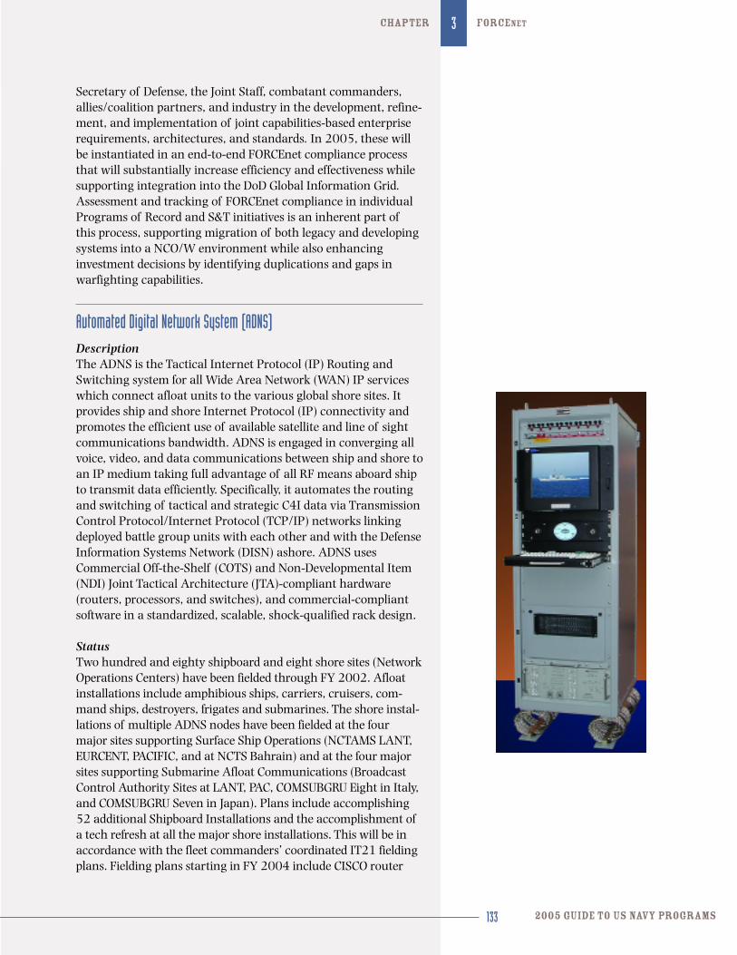
Automated Digital Network System (ADNS)DescriptionThe ADNS is the Tactical Internet Protocol (IP) Routing andSwitching system for all Wide Area Network (WAN) IP serviceswhich connect afloat units to the various global shore sites. Itprovides ship and shore Internet Protocol (IP) connectivity andpromotes the efficient use of available satellite and line of sightcommunications bandwidth. ADNS is engaged in converging allvoice, video, and data communications between ship and shore toan IP medium taking full advantage of all RF means aboard shipto transmit data efficiently. Specifically, it automates the routingand switching of tactical and strategic C4I data via TransmissionControl Protocol/Internet Protocol (TCP/IP) networks linkingdeployed battle group units with each other and with the DefenseInformation Systems Network (DISN) ashore. ADNS usesCommercial Off-the-Shelf (COTS) and Non-Developmental Item(NDI) Joint Tactical Architecture (JTA)-compliant hardware(routers, processors, and switches), and commercial-compliantsoftware in a standardized, scalable, shock-qualified rack design.
StatusTwo hundred and eighty shipboard and eight shore sites (NetworkOperations Centers) have been fielded through FY 2002. Afloatinstallations include amphibious ships, carriers, cruisers, com-mand ships, destroyers, frigates and submarines. The shore instal-lations of multiple ADNS nodes have been fielded at the fourmajor sites supporting Surface Ship Operations (NCTAMS LANT,EURCENT, PACIFIC, and at NCTS Bahrain) and at the four majorsites supporting Submarine Afloat Communications (BroadcastControl Authority Sites at LANT, PAC, COMSUBGRU Eight in Italy,and COMSUBGRU Seven in Japan). Plans include accomplishing52 additional Shipboard Installations and the accomplishment ofa tech refresh at all the major shore installations. This will be inaccordance with the fleet commanders’ coordinated IT21 fieldingplans. Fielding plans starting in FY 2004 include CISCO router
133 2005 guide to US Navy programs
FORCENet3chapter
134vision / presence / power
3 chapter requirements to capabilities
backfit plan, the submarine variant that will include the shoreBCA, fielding of the SCN-variant, and determination and fieldingof a new baseband system. FY 2005 completes the CISCO backfit,starts Increment II fielding and Increment II plus which will elimi-nate bandwidth bottlenecks on large deck platforms. Plans alsocall for technology integration of Quality and Class of Service(QoS/CoS) with either new router templates or implementation ofa “Packet Shaper” technology. This technology will start to beimplemented with ADNS Increment II.
DevelopersSPAWAR Systems Center Code 2631; San Jose, California Science Applications International Corporation;
Arlington, Virginia. Primary vendor - Cisco: San Jose, California
Link-11/16/22 Advanced Tactical Data Link Systems (ATDLS)DescriptionThe ATDLS program develops, fields, and supports joint andcoalition Tactical Data Link (TDL) capabilities. These joint TDLSinclude terminals, gateways, networks, and support initiativesthat improve TDL connectivity, promote equipment commonalityand interoperability, and provide training and fleet support. Link-11 is used by Navy, Air Force, Army, Marine Corps, and alliedships and aircraft, many of which are also equipped with Link-16. In accordance with the Joint Tactical Data Link ManagementPlan (JTDLMP), Link-11, which uses the M-series message stan-dard, is scheduled to be shut down no later than 2015. Link-16,which uses the J-series message standard, has been designated asthe DoD primary Tactical Data Link. The Navy is implementingLink-16 in most of its link-capable platforms. As the JTDLMPapproved replacement for Link-11, Link-22 is a multi-nationaldevelopment effort and will use the J-Series message standard.Major supported efforts are as follows:
> Terminals: Joint Tactical Information Distribution System (JTIDS),
Multifunctional Information Distribution System (MIDS) Low
Volume Terminal (LVT), MIDS Joint Tactical Radio System (JTRS),
and the Common Shipboard Data Terminal Set (CSDTS)
> Gateways: Command and Control Processor (C2P), Common Data
Link Management System (CDLMS), Next Generation C2P, and
Common Link Integration Processing (CLIP)
> Support Initiatives: Joint Interface Control Officer (JICO) Support
System (JSS), Dynamic Network Management (DNM)
These capabilities allow more effective employment of fleet units by improving timeliness, accuracy, and content oftactical data transfer.
135 2005 guide to US Navy programs
FORCENet3chapter
StatusSee following FORCEnet program descriptions on pages 134-173.
DevelopersData Link Solutions (DLS); Cedar Rapids, IowaViaSat Inc., Carlsbad; CaliforniaAdvanced Programing Concepts; Austin, TexasBAE Systems Wayne; New JerseyDRS, Inc., Wyndmoor; PennsylvaniaNorthrop Grumman Information Tech; Sorrento Valley, California
Base Level Information Infrastructure (BLII)DescriptionBLII is the program of record that modernizes IT facilities at 16OCONUS Navy bases, stations, and headquarters. It installs new,or upgrades existing infrastructure to provide state-of-the-art ITcapability. Further, the program installs the hardware, software,and enterprise management tools to enable a fully integrated,interoperable, and secure IT network for rapid and reliable trans-fer of data, voice, and video. The program also replaces orupgrades obsolete telephone switches at 140 CONUS andOCONUS locations. Major functional areas of BLII are:
OCONUS IT infrastructure modernization
> Installs/modernizes base and building cable plants; WAN, BAN,
and LAN electronics; information assurance; network management;
configuration management; and asset management capabilities
> Provides engineering and operations expertise at the IT Service
Centers and the IT Outreach Centers
> Installs and sustains system hardware, software and related training
OCONUS force protection (IT)
> Installs/modernizes OCONUS pier IT infrastructure to IT-21stan-
dards (Equal to or better capability pier-side as ships had at sea)
> Provides engineering, operations and maintenance support to the
newly installed IT infrastructure
> Expands SIPRNET capability at OCONUS locations
Naval Network and Space Command (NNSOC) telephone switch replacement/modernization
> Replaces obsolete telephone switches and upgrades firmware and
software on a progressive schedule to ensure compliance with JCS
directives and the recently enacted Public Law 107-314 at the 140
NNSOC telephone switch locations that service our forward deployed
OCONUS and CONUS support forces
> Modernizes telephone switch cable plants
136vision / presence / power
3 chapter requirements to capabilities
StatusThe backbone phase of the OCONUS IT infrastructure moderniza-tion is rapidly coming to conclusion at the 16 designated overseasfleet concentration centers. The next major phase of the OCONUSIT modernization is to bring users to the new physical infrastruc-ture followed by the migration of these users to the new OCONUSenterprise network. Funding is in place to continue this evolutionto include technical upgrades and technology insertion throughFY 2011. The replacement and upgrade of the Navy’s telephoneswitches is accomplished on a progressive and systemic scheduleto meet the OSD/Joint Staff mandated timeframe.
DevelopersNavy policy is to procure only hardware and software from theDISA JITC tested/certified/interoperable “Approved ProductsList.” All hardware and software procured and installed in con-junction with the BLII POR is under the cognizance of PEO C4Iand Space (PMW 790). CNO N71, NETWARCOM and the PMWmaintain close synchronization in the requirements validation,acquisition, installation and logistics process.
Command and Control Processor (C2P)DescriptionThe C2P serves as the interface and the data translator betweenthe surface platform’s Combat Direction System (CDS) and theTactical Data Links (TDL). It is considered a gateway as describedin the ATDLs discussion above. It is the data forwarder betweenLinks-11 and 16. In 1984, implementation of JTIDS/Link-16based CDSs commenced with the Advanced Combat DirectionSystem (ACDS) Model 5. The ACDS Model 5 contract had anoption for development of a C2P to provide the functionality of the TDL Communication Processor. Also in 1984, theOperational Requirement (OR) for the C2P was established. Theoperating program of UYQ-62 (V), the initial C2P variant, wascoded in CMS-2 and hosted in a single UYK-43. When develop-ment of ACDS Model 5 was delayed, the C2P was modified to sup-port Model 4 (Link-11) based surface platforms. This allowedinstallation of C2P and JTIDS/Link-16 aboard Model 4 AEGISand ACDS Block 0 ships. With this capability, C2P serves as agateway to connect a Link-16 network to a legacy Link-11 net-work. C2P Model 4 successfully completed OPEVAL in a com-bined test with Link-16 in FY 1994. C2P Model 5 successfullycompleted OPEVAL in FY 2000. The approaching obsolescence ofthe C2P computer brought about the need to identify a suitablehardware set to re-host the functionality of the C2P. As a practi-cal and cost-effective option, the C2P re-host initiative was joinedwith another initiative that encompassed the concept of co-locat-ing multiple tactical link management, coordination, and moni-toring in a single host.
137 2005 guide to US Navy programs
FORCENet3chapter
StatusThe C2P is fully fielded with the capability being re-hosted as soft-ware within the Common Data Link Management System andNext Generation C2P.
Common Data Link Management System (CDLMS)DescriptionThe CDLMS initiative extends the functionality of the Commandand Control Processor by consolidating several functions previous-ly performed by separate systems or subsystems, and providingimproved Human Machine Interface (HMI) and Link maintenance.CDLMS also incorporates the Link Monitoring System (LMS) alongwith supporting the initial phase of development of the CommonShipboard Data Terminal Set (CSDTS). The CSDTS initiative pro-vides the next generation Link-11 data terminal replacing legacyLink-11 terminal hardware while incorporating Multi-FrequencyLink-11 (MFL), Satellite Link-11, and supporting the initial DualNet Link-11. Re-hosting the C2P within CDLMS provides the samefunctionality in COTS hardware, namely the UYQ-70 console,which makes the system easier and less expensive to upgrade. TheCDLMS integrates the CSDTS and C2P (Rehost) in a set of VMEcards to provide consolidated displays and controls to monitormulti-TDL networks simultaneously. The CDLMS/ C2P(R) programhas fielded the USQ-86 (V), consisting primarily of an UYQ-70 EPShousing four VME chassis. Three of these are populated with VMEcard sets for the following: C2P(R), CSDTS, and the LinkManagement/ Monitoring Com-ponent. This hardware configura-tion supports the transformation to Next Generation C2P (NGC2P),which conceivably will take the place of the current C2P(R).CDLMS has successfully completed Aegis and SSDS Combat SystemIntegration and Test (CSIT) and is currently being installed.CSDTS implementation is ongoing, enabled by, but separate from,CDLMS/C2P(R).
StatusCDLMS is being fielded.
DevelopersGSA/Anteon; Fairfax, Virginia DRS Inc.; Wyndmoor, Pennsylvania
Common Link Integration Processing (CLIP)DescriptionThe Navy and Air Force have jointly entered into the CLIP initia-tive. CLIP is envisioned as an open architecture software-basedcommon Tactical Data Link (TDL) message processing and inte-gration capability with applications across various military plat-forms and installations, including air, surface, C2 shore sites, and ground-based tactical units. A chief objective is to providegreater interoperability and reduce implementation cost. CLIPwill be an evolutionary spiral development process with function-ality specified at each delivery point to match platform TDLrequirements. It will provide the interface to all the various com-munication systems including current terminals and radios aswell as those under development such as JTRS. It will act as agateway providing translations and data forwarding to legacysystems and be the primary interface to any host system (i.e.,combat). CLIP is envisioned to be primarily software that canreside on any operating system or hardware.
StatusA CLIP MOA between PEO-C4I & Space and Air Force ElectronicSystems Center was signed in August 2003. An AcquisitionDocumentation Package including an Acquisition Strategy (AS),Acquisition Program Baseline (APB) and an ACAT designationletter for the proposed ACAT II program is currently in staffing at PEO-C4I & Space and will be forwarded to ASN (RD&A) forapproval. Contract awarded in May 2005.
DevelopersNorthrop Grumman: Reston, Virginia
Combined Enterprise Regional Information Exchange System (CENTRIXS)DescriptionCENTRIXS enables ship-to-ship and ship-to-shore Web replication,secure e-mail, chat communications over SATCOM with allied/coalition partners. It also provides a ship-to-shore SATCOM IP pathto compliment existing ship-to-ship HF e-mail capabilities. The net-work infrastructure is implemented by using a combination of net-work switches, routers, crypto, servers, PCs and commercial net-works technologies. CENTRIXS supports seven different enclavesavailable to the warfighter: CENTRIXS Four eyes (AUS/CAN/UK/US); CENTRIXS Japan (J); CENTRIXS Korea (K); NATO InitialData Transfer System (NIDTS); Global Counter Terrorism TaskForce (GCTF); Combined Naval Forces CENTCOM (CNFC); andMulti Coalition Forces Iraq (MCFI). Currently, the Pacific RegionNetwork Operations Center (PRNOC) is the only network hub forall CENTRIXS connectivity. CENTCOM has directed that all shipsdeploying to NAVCENT AOR have CENTRIXS capability.
138vision / presence / power
3 chapter requirements to capabilities
139 2005 guide to US Navy programs
FORCENet3chapter
Status147 of 153 Navy deployable warships have coalition connectivi-ty. This includes a separate shipboard coalition LAN/WAN withrespective infrastructure, servers and work stations. Under cur-rent procurement and installation funding, FOC for CENTRIXS is 2018.
DevelopersHardware for procurement and development of ISNS is under he cognizance of PEO C4I/Space PMW 160 as well as OPNAV(N71). These organizations work together to identify and imple-ment the latest technologies to ensure proper implementationinto the program. Engineering, development, integration, instal-lation, training, and life cycle support will be accomplishedthrough Navy and Defense Department activities.
Commercial Satellite Communications: Commercial Wideband SATCOM Program (CWSP)DescriptionThe CWSP, formerly known as Challenge Athena, is a full-duplex,high data-rate communications link that operates in the C-bandspectrum up to 2.048 Mbps. The CWSP terminal (WSC-8(V)1, 2)with modifications by the developer/manufacturer is also capableof operating in the Ku-band spectrum. Because of open ocean lim-itations, there are currently no plans to enhance the Navy’s com-mercial satellite terminal to include Ku coverage. CWSP is capableof providing access to voice, video, data, and imagery circuitrequirements. It supports fleet commander flagships (LCC/AGF),aircraft carriers (CV/CVN), amphibious ships (LHA/LHD/LPD)and other selected ships, including hospital ships (T-AH) and sub-marine tenders (AS). Terminals are also installed at schoolhouselocations in San Diego, Calif., and Norfolk, Va.
Examples of specific communications circuits that are providedinclude: Distibuted Common Ground Surface System—Navy(DCGS-N), Video Tele-Conferencing (VTC), Video InformationExchange system (VIXS), Video Tele-Medicine (VTM), Video Tele-Training (VTT), Afloat Personal Telephone Service (APTS),Integrated Digital Switching Network (IDSN) for voice/telephone,Secret/ Unclassified Internet Protocol Router Networks (SIPRNET/NIPRNET), and Joint Worldwide Intelligence CommunicationsSystem (JWICS). The CWSP terminal uses commercial satelliteconnectivity and COTS/NDI Equipment. It has transitioned from augmentation, to surge, and in recent years has become an integral part of Navy’s SATCOM architecture because ofthe existing and extremely overburdened military satellite communications systems.
140vision / presence / power
3 chapter requirements to capabilities
StatusThe majority of CWSP terminals procured have been installed on32 ships. Five additional terminals are planned on new construc-tion ships (CVN and LPD). Commercial leasing options for satel-lite capacity continue to be evaluated. The program office is con-sidering options to refurbish the aging CWSP (WSC-8) terminals.
DevelopersVarious COTS/NDI.
Distributed Common Ground/Surface System—Navy (DCGS-N)DescriptionDCGS-N is the Intelligence, Surveillance, Reconnaissance, andTargeting (ISR&T) processing and exploitation component ofFORCEnet that will support all levels of the command and controldecision process. The Navy DCGS merges ISR&T, mission planning,and situational awareness functions into a Web-enabled, network-centric, joint-interoperable architecture. DCGS-N will support theNavy’s command and control tiers of numbered fleet command shipsand ashore command centers (Tier 1); carrier strike group/ expedi-tionary strike group (Tier 2); and unit level strike platforms (Tier 3).Each tier will have a scalable set of DCGS-N capabilities to support itsassigned roles and missions. DCGS-N will utilize network-centric,multi-intelligence processing and exploitation to support the Task,Post, Process, Use (TPPU) process for the Commander Joint Task Forceand the maritime warfighter. Leveraging existing SPAWAR (GCCS-M),NAVAIR (JSIPS-N), and NAVSEA (TES-N) programs, DCGS-N includestimely interfaces to national, joint, theater, and organic sensors. Theaim points generated by DCGS-N will be provided to a variety of air,surface, and sub-surface launched precision guided weapons systems.DCGS-N will be interoperable with the DCGS elements of the otherservices through the use of the DCGS Integration Backbone (DIB) asthe foundation of the DCGS-N architecture.
StatusA total of 34 systems are currently planned for installationbetween FY 2007 and FY 2010 on aircraft carriers, large-deckamphibious ships, fleet command ships, and designated shore-based reach-back support sites. Fleet Forces Command andOPNAV are working together to determine the appropriateafloat/shore-based architecture and fielding plan that will meet fleet ISR exploitation and targeting requirements.
DevelopersNorthrop Grumman: Linthicum, MarylandRaytheon: Garland, TexasSAIC: Columbia, MarylandBAE Systems: Ranchero Bernardo, CaliforniaLMSI: Valley Forge, PennsylvaniaTitan Systems: Chantilly, Virginia
141 2005 guide to US Navy programs
FORCENet3chapter
Deployable Joint Command and Control Capability (DJC2)DescriptionThe DJC2 is a joint DoD transformation initiative, with Navy as the lead component, to provide a standardized deployableCommand and Control (C2) capability for Regional CombatantCommanders (COCOMs) and Joint Force Commanders (JFCs).Fielding of DJC2 will greatly reduce the ad hoc nature of JointTask Force (JTF) C2. DJC2 will provide the JFC with a level ofC2 application integration that currently only exists for theComponent Command (and below) headquarters. Theater levelelements (e.g. Joint Communications Support Element) will pro-vide the communications links for the fully deployed system.DJC2 will build upon the Joint Global Command and ControlSystem (GCCS-J), the Joint Forces Command developedCollaborative Information Environment (CIE) toolkit and existingjoint and service C2 programs (especially the GCCS family ofsystems), and lessons learned from OEF and OIF, to equip theRegional COCOMs and JFCs with a tested C2 system that is:
> Horizontally and vertically integrated across all levels of command
> Interoperable across joint, coalition, interagency, Non-
> Robust, scalable, and rapidly deployable, including an
en-route capability
Spiral development and fielding of evolving technology will helpto meet regional COCOM and JTF requirements. The first step willbe compilation and review of all ongoing C2 efforts includingScience and Technology (S&T) initiatives, Advance ConceptTechnology Demonstrations (ACTDs), programs of record, andfielded capabilities.
StatusThe JROC validated the DJC2 Mission Need Statement (MNS) inFebruary 2002. DJC2 received milestone A approval in May2002. The analysis of alternatives was completed in July 2003and the Operational Requirements Document (ORD) approved bythe Joint Requirements Oversight Council (JROC) in September2003. Milestone B approval was granted in March 2004. TheCapability Production Document (CPD) was approved by theJROC in November 2004. The Navy acquired the developmentalexperimentation suite for Joint Forces Command in FY 2004. Theinitial operational DJC2 delivery will be to the Pacific Commandin FY 2005, followed by a delivery to the Central Command,intended to provide a tech-refresh to the CENTCOM DeployableHeadquarters (CDHQ) in FY 2005. Other planned DJC2 deliveriesare: European Command, FY 2006; Southern Command, FY2007; and a maritime variant in FY 2009.
142vision / presence / power
3 chapter requirements to capabilities
DevelopersTitan: Panama City, FloridaLockheed Martin: Panama City, FloridaNorthrup Grumman: Arlington, VirginiaBMP COE: Arlington, VirginiaKSJ & Associates: Alexandria, VirginiaARA: Panama City, FloridaAnteon: Panama City, Florida
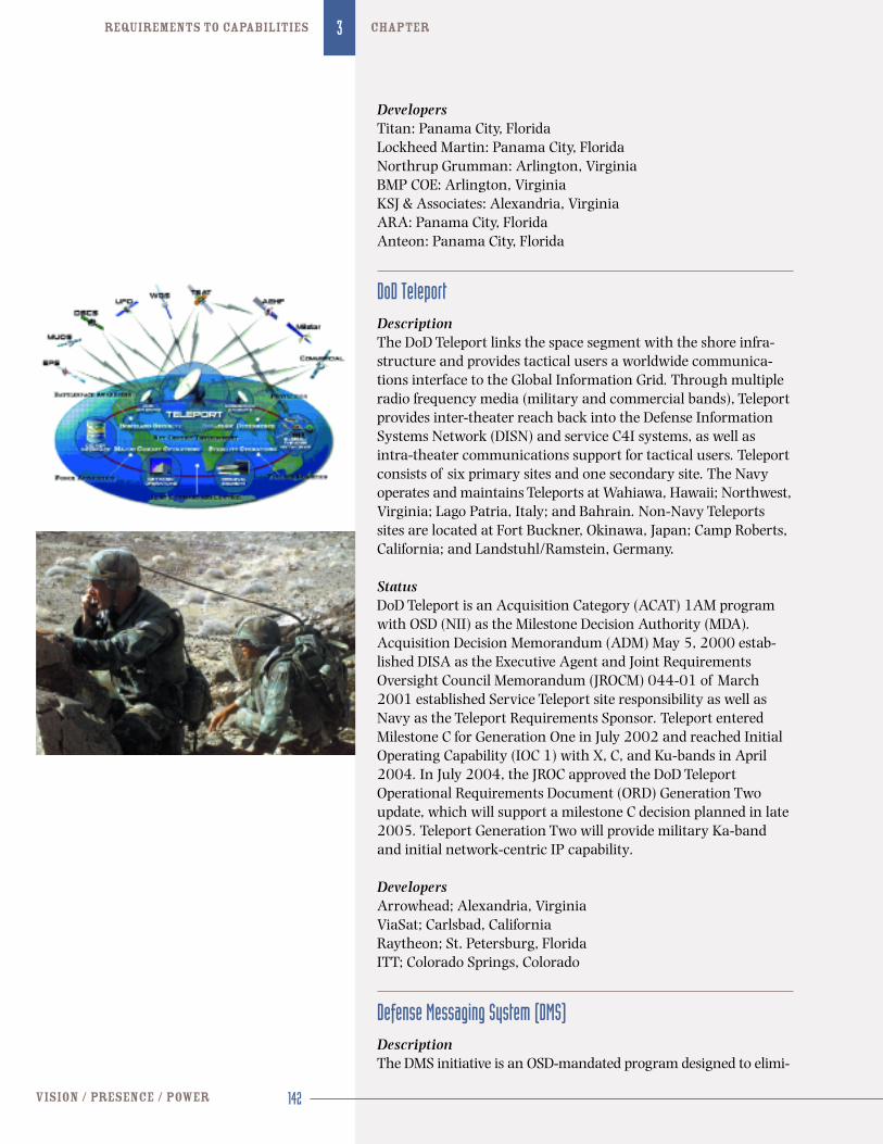
DoD TeleportDescriptionThe DoD Teleport links the space segment with the shore infra-structure and provides tactical users a worldwide communica-tions interface to the Global Information Grid. Through multipleradio frequency media (military and commercial bands), Teleportprovides inter-theater reach back into the Defense InformationSystems Network (DISN) and service C4I systems, as well asintra-theater communications support for tactical users. Teleportconsists of six primary sites and one secondary site. The Navyoperates and maintains Teleports at Wahiawa, Hawaii; Northwest,Virginia; Lago Patria, Italy; and Bahrain. Non-Navy Teleportssites are located at Fort Buckner, Okinawa, Japan; Camp Roberts,California; and Landstuhl/Ramstein, Germany.
StatusDoD Teleport is an Acquisition Category (ACAT) 1AM programwith OSD (NII) as the Milestone Decision Authority (MDA).Acquisition Decision Memorandum (ADM) May 5, 2000 estab-lished DISA as the Executive Agent and Joint RequirementsOversight Council Memorandum (JROCM) 044-01 of March2001 established Service Teleport site responsibility as well asNavy as the Teleport Requirements Sponsor. Teleport enteredMilestone C for Generation One in July 2002 and reached InitialOperating Capability (IOC 1) with X, C, and Ku-bands in April2004. In July 2004, the JROC approved the DoD TeleportOperational Requirements Document (ORD) Generation Twoupdate, which will support a milestone C decision planned in late2005. Teleport Generation Two will provide military Ka-bandand initial network-centric IP capability.
DevelopersArrowhead; Alexandria, Virginia ViaSat; Carlsbad, CaliforniaRaytheon; St. Petersburg, Florida ITT; Colorado Springs, Colorado
Defense Messaging System (DMS)DescriptionThe DMS initiative is an OSD-mandated program designed to elimi-
nate the multitude of expensive “stovepipe” legacy record messag-ing systems that provide organizational and individual messagetraffic between operational units. The DMS architecture has beenderived using the Multi-command Required Operational Capability(MROC) requirements and has been targeted to provide the armedservices and agencies with a high assurance messaging capability.The DMS provides messaging, directory, and management services.
StatusCurrent DoD implementation of DMS closed the DMS Transit-ional Hubs (DTHs) for GENSER on September 30, 2003 and forEmergency Action Message (EAM) messaging on February 22,2004. Navy is transitioning to a Web-based interface known asthe DMS Expanded Boundry Solution (DEBS). The transition toDEBS will be completed in 2007.
DevelopersLockheed Martin; Manassas, Virginia
Dynamic Network Management (DNM)DescriptionDNM will correct Link-16 network management limitations andprovide the warfighter greater flexibility in the use of Link-16.DNM will facilitate automated net entry/exit of additional plat-forms in the future, including smart weapons with a WeaponsData Link (WDL), and will provide a real-time capability to modify Link-16 network parameters with existing messages tomeet evolving changes in the theater. DNM will also enable capa-bilities such as IP over Link-16, variable update and throughputrates, monitoring and analyzing of real-time network loading,and executing stacked and multi-net operations. DNM is essentialto reducing Link-16 network saturation and is an enabler for theJICO Support System (JSS). It also provides essential support fortime critical targeting and time critical strike.
StatusThe Air Force plans to award contracts for JICO Support System(JSS) Block 1, which incorporates DNM technology, in March2005 to two vendors followed by a down-select to a singlevendor. Initial JSS Block 1 is planned for shipboard testing in late2005. The DNM program will enable a fully tested and interoper-able version of the platform’s host system, known as the JointHost Demand Algorithm (JHDA), in the shipboard Command andControl Processor (C2P) in early FY 2006. A random accessmode that provides a nodeless, flexible, and scalable means ofadapting the network to rapid changes in topology and messagetraffic conditions, known as SHUMA, is being lab tested.
DevelopersSPAWARSYSCEN; San Diego, California Northrop Grumman; San Diego, California
143 2005 guide to US Navy programs
FORCENet3chapter
Global Broadcast Service (GBS)DescriptionThe GBS can augment and interface with other communicationssystems to provide virtual two-way network to deliver a high-speed, one-way flow of high-volume information disseminatedquickly by broadcast to proliferated, low-echelon, geographicallydispersed users supporting situational awareness, weapons tar-geting, intelligence, and homeland defensive operations. GBS cansupport military operations with U.S. allies or coalition forces andnon-DoD governmental organizations. GBS will revolutionizecommunications with increased capacity, faster delivery of data,near-real-time receipt of imagery and data to the warfighter, andreduced over-subscription of current MILSATCOM systems.
StatusThe Navy is fielding receive-suites on carriers, larger-deck amphibi-ous warfare ships, command ships, guided missile submarines(SSGN), and half of the nuclear-powered attack submarines (SSN).Guided missile cruisers, destroyers, and strategic missile submarinesare required, but not funded. Transition to an IP-based enhancedarchitecture should be completed by September 2005. Theenhanced architecture provides a nearly doubling worldwide capac-ity with potentially eight times more coverage. Afloat-platform capa-bility will have up to six multiple-receive channels (each up to 24Mbps) and support additional security enclaves (each of 70 Mbps).Compartmented enclaves such as a top secret or allied broadcast arenot funded. Within bandwidth there are no constraints on the num-ber of concurrent video stream products received for viewing oncomputer workstations across attached networks. The enhancedarchitecture permits improved sharing and reallocation of broad-cast coverage and bandwidth between, users, information product,media types, and security levels. The system is more queue driven,priority based rather than scheduled based. On the larger, morecapable ships or fixed shore platforms the enhanced architecturewill also permit multiple satellite receive capability, including UFOand WGS or commercial satellites, concurrently.
In January 2005 the DoD approved new and maturing opera-tional requirements defining spiral development, including auto-mated satellite spot beam sharing (important naval requirement),two-way transmit receive suites, better management of new spacesegment resources, enhanced GIG integration, suit-case and rucksack portable receive suites, communications-on-the-moveground mobile receive suites, terrestrial wireless rebroadcastreceive suites, global system-wide management and content shar-ing, flexible system restoration, and bandwidth efficiency metricreporting for better planning and system allocation planning.
DevelopersJoint Program Office: U.S. Air Force, Space and Missile SystemsCenter/Raytheon; El Segundo, California
144vision / presence / power
3 chapter requirements to capabilities
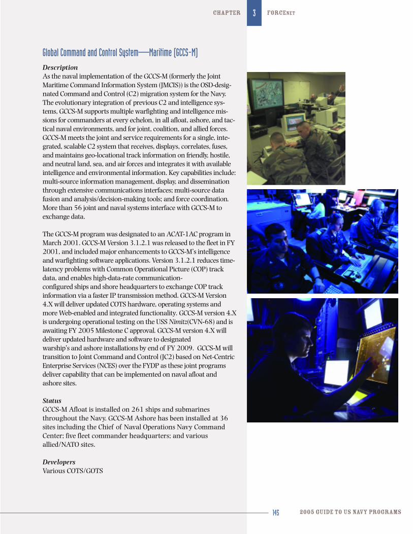
Global Command and Control System—Maritime (GCCS-M)DescriptionAs the naval implementation of the GCCS-M (formerly the JointMaritime Command Information System (JMCIS)) is the OSD-desig-nated Command and Control (C2) migration system for the Navy.The evolutionary integration of previous C2 and intelligence sys-tems, GCCS-M supports multiple warfighting and intelligence mis-sions for commanders at every echelon, in all afloat, ashore, and tac-tical naval environments, and for joint, coalition, and allied forces.GCCS-M meets the joint and service requirements for a single, inte-grated, scalable C2 system that receives, displays, correlates, fuses,and maintains geo-locational track information on friendly, hostile,and neutral land, sea, and air forces and integrates it with availableintelligence and environmental information. Key capabilities include:multi-source information management, display, and disseminationthrough extensive communications interfaces; multi-source datafusion and analysis/decision-making tools; and force coordination.More than 56 joint and naval systems interface with GCCS-M toexchange data.
The GCCS-M program was designated to an ACAT-1AC program inMarch 2001. GCCS-M Version 3.1.2.1 was released to the fleet in FY2001, and included major enhancements to GCCS-M’s intelligenceand warfighting software applications. Version 3.1.2.1 reduces time-latency problems with Common Operational Picture (COP) trackdata, and enables high-data-rate communication-configured ships and shore headquarters to exchange COP trackinformation via a faster IP transmission method. GCCS-M Version4.X will deliver updated COTS hardware, operating systems andmore Web-enabled and integrated functionality. GCCS-M version 4.Xis undergoing operational testing on the USS Nimitz(CVN-68) and isawaiting FY 2005 Milestone C approval. GCCS-M version 4.X willdeliver updated hardware and software to designated warship’s and ashore installations by end of FY 2009. GCCS-M willtransition to Joint Command and Control (JC2) based on Net-CentricEnterprise Services (NCES) over the FYDP as these joint programsdeliver capability that can be implemented on naval afloat andashore sites.
StatusGCCS-M Afloat is installed on 261 ships and submarinesthroughout the Navy. GCCS-M Ashore has been installed at 36sites including the Chief of Naval Operations Navy CommandCenter; five fleet commander headquarters; and variousallied/NATO sites.
DevelopersVarious COTS/GOTS
145 2005 guide to US Navy programs
FORCENet3chapter
146vision / presence / power
3 chapter requirements to capabilities
Information Assurance (IA)DescriptionIA is defined as information operations that protect and defendinformation and Information Systems (IS) by ensuring theirauthenticity, availability, confidentiality, data integrity, and non-repudiation. The Navy’s primary IA program is InformationSystems Security Program (ISSP).
FORCEnet is the Navy’s component to the DoD GlobalInformation Grid. The Navy has embraced a Defense-in-Depthstrategy to protect FORCEnet by employing multiple layers ofprotection starting at the desktops. The IA Technical Framework(IATF) has been adopted and divides ISSP resources into threefundamental categories: technology, operations, and people. The IATF provides a documented source of technical solutionsand guidance mapped to the Defense-in-Depth goals. Selection, training, and retention of network security specialists are vitalelements in our ISSP arsenal.
ISSP focuses on development, acquisition, implementation,upgrade of the CND products and services such as firewalls,guards, Virtual Private Networks (VPN), intrusion detection sys-tems, electronic key management systems, Public KeyInfrastructure (PKI), and Common Access Cards (CAC). ISSP alsofocuses on the development of new cryptographic technologythat can support a wide variety of applications and algorithms.
StatusAcquisition vehicles are in place for TYPE I CommunicationsSecurity (COMSEC) and TYPE II COTS technologies to support theNavy’s bandwidth requirements for secure voice and data, andPKI under the expanding umbrella of Key ManagementInfrastructure highlighted by the Navy’s contributions to theDoD’s Crypto Modernization (CM) program.
DevelopersSpace and Naval Warfare Systems Command (SPAWAR) providesoperational support to Navy warfighter by disseminating IAinformation and providing technical services.
Integrated Broadcast Service/Joint Tactical Terminal (IBS/JTT)DescriptionThe IBS is a system-of-systems that will migrate the TacticalReceive Equipment and Related Applications Data DisseminationSystem (TDDS), Tactical Information Broadcast Service (TIBS),Tactical Reconnaissance Intelligence Exchange System (TRIXS),and Near Real-Time Dissemination (NRTD) system into an inte-grated service with a common format. The IBS will send data via
communications paths, such as UHF, SHF, EHF, GBS, and via net-works. This program supports Indications Warning (I&W), sur-veillance, and targeting data requirements of tactical and opera-tional commanders and targeting staffs across all warfare areas.It comprises broadcast-generation and transceiver equipmentthat provides intelligence data to tactical users. The Joint TacticalTerminal (JTT) will receive, decrypt, process, format, distribute,and transmit tactical data according to preset user-defined crite-ria across open-architecture equipment. JTT will be modular andwill have the capability to receive all current tactical intelligencebroadcasts (TDDS, TADIXS-B, TIBS, and TRIXS). JTT will also beinteroperable with the follow-on IBS UHF broadcasts. However,the current JTT form factor does not meet space and weight con-straints for a majority of the Navy and Air Force airborne plat-forms. Therefore, to ensure joint interoperability, the Navy andAir Force will continue to support the current Multi-missionAirborne Tactical Terminal (MATT) through a low cost Pre-Planned Product Improvement (P3I) program until the transitionto an IBS capable JTRS airborne variant starting in FY 2007.
StatusA receive-only JTT was delivered to the Navy for early integrationefforts in the third quarter FY 2000. The Navy received the firstfour fully capable JTTs (with transmit capability) in third quarterFY 2001. The Navy commenced shipboard installations in fourthQuarter FY 2001 for developmental testing. OT&E will occur inthird quarter FY 2005. JTT fielding has occurred from 2001 to2004. Additional installations are anticipated in 2006 and 2007.The JTTs will continue to receive the legacy broadcasts (e.g.TDDS, TIBS, TRIXS) until next-generation broadcast services aredeveloped and fielded.
DeveloperIBS: TITAN/BTGJTT: Raytheon Systems; St. Petersburg, Florida
Integrated Shipboard Network System (ISNS)DescriptionThe ISNS program is a derivative of the common elements fromvarious other programs of record with the purpose of providingrobust LANs on all Navy ships. ISNS provides integration andsupport for all requisite classifications (i.e., SCI, TS, secret, non-U.S., and unclassified). The ISNS program implements networksusing a combination of network switches, hubs, routers, servers,PCs and commercial network software application technologies.It provides the capability to establish connectivity to the DefenseInformation Systems Network (DISN) WAN for global informa-tion distribution. In addition, it provides internal information dissemination capabilities for individual fleet units. By providing
147 2005 guide to US Navy programs
FORCENet3chapter
the infrastructure for shipboard C4I programs, ISNS facilitatesimplementation of the Navy’s IT-21 strategy and is an enabler for network-centric warfare. It provides the transport medium forWeb-enabling all IT-21 related programs (i.e., NTCSS, GCCS-M,Voice-Video-Data (VVD)). ISNS networks support the robustinformation flow requirements necessary to achieve Sea Power 21capabilities, as well as providing the backbone for informationinteroperability with coalition forces.
StatusISNS installations have transitioned from ATM networks to theGigabit Ethernet architecture. Under current procurement andinstallation funding, IOC for ISNS is 2011.
DevelopersHardware for procurement and development of ISNS is under thecognizance of PEO C4I/Space PMW 165 as well as OPNAV(N71). These organizations work together to identify and imple-ment the latest technologies to ensure proper implementationinto the program. Engineering, development, integration, instal-lation, training, and life cycle support will be accomplishedthrough Navy and Defense Department activities.
Joint Interface Control Officer (JICO) Support System (JSS)DescriptionThe JSS is a “tool set” enabling the JICO to properly plan andmanage the Multi-Tactical Data Link (TDL) network in buildingand maintaining the Common Tactical Picture (CTP) in supportof the Joint Force Commander. The CTP is the near-real time pic-ture of air, space, surface, land and subsurface vehicular tracksas well as points, lines and areas. Because the CTP is the productof data provided primarily by the Joint Data Network (JDN), theJICO also serves as the theater JDN Manager. The JDN includesthe Joint Force Multi-TDL network and those interfaces betweenthe Multi-TDL network and national data nets. As JDN Manager,JICO plans, implements, monitors and manages the joint forceMulti-TDL architecture and controls those interfaces betweenInterface Units (IUs) in the Joint Task Force and other networksthat contribute data to the CTP.
StatusContract awarded in May 2005.
DevelopersNorthrup Grumman, Reston, Virginia
148vision / presence / power
3 chapter requirements to capabilities
149 2005 guide to US Navy programs
FORCENet3chapter
Joint Tactical Information Distribution System (JTIDS)DescriptionThis digital information-distribution system provides rapid,secure, jam-resistant (frequency-hopping) communications, navigation, and identification capabilities appropriate for militaryuse up to and including secret information. A joint programdirected by OSD, JTIDS provides crypto-secure, jam-resistant, andlow-probability-of-exploitation tactical data and voice communi-cation at a high data rate to Navy tactical aircraft and ships andMarine Corps units. JTIDS also provides capabilities for common-grid navigation and automatic communications relay. It has been integrated into numerous platforms and systems, includingNavy aircraft carriers, surface warships, amphibious assaultships, and E-2C Hawkeye aircraft; Air Force Airborne Warningand Command System (AWACS) aircraft; and Marine CorpsTactical Air Operations Centers (TAOCs) and Tactical AirCommand Centers (TACCs). Other service and foreign countryparticipants include the Army, Great Britain, and Canada.Additionally, JTIDS has been identified as the preferred communi-cations link for Theater Ballistic Missile Defense programs. JTIDSis the first implementation of the Link-16 Joint Message Standard(J-series) and provides the single, near real-time, joint data linknetwork for information exchange among joint and combinedforces for command and control of tactical operations.
StatusThe Air Force is the lead service for JTIDS. The program successful-ly completed OPEVAL in August 1994 and was authorized to enterfull-rate production in March 1995. Production is now complete.The Multifunctional Information Distribution System (MIDS) LowVolume Terminal (LVT) is the Pre-Planned Product Improvement(P3I) to the JTIDS terminal. The MIDS Joint Tactical Radio System(JTRS) terminal is the funded follow-on to MIDS LVT.
DevelopersGEC-Marconi Electronics Systems; Wayne, New JerseyRockwell-Collins Avionics; Cedar Rapids, Iowa Northrop Grumman; Bethpage, New York
Joint Tactical Radio System (JTRS)DescriptionThe JTRS is a software-programmable multi-band, multi-mode fami-ly of networkable radios capable of simultaneous voice, data, andvideo communications. The program will effect the migration ofmore than 25 radio families, encompassing thousands of radio sys-tems, to the JTRS family of radio systems. All radios will be compliantwith Software Communications Architecture (SCA), a single, open-system architecture. SCA, now at version 2.2, provides the standards
for all JTR software in the future. In addition, JTRS will be developedwith a focus toward integrated GIG transformational capabilities. Atthe same time the JTRS will be backwards compatible with selectedlegacy radio systems. At present there are five designated clustersthat make up the JTRS family across DoD: handheld; man-packed;vehicular; airborne/maritime/fixed; and small form-fit. The JTRSrequirements are derived from the Joint Tactical Radio System (JTRS)Operational Requirements Document (ORD) Version 3.2 dated April9, 2003. This Joint ORD is updated annually to incorporate addition-al validated requirements gathered from all the DoD Services. TheORD is currently being converted to a capabilities development docu-ment. JTRS will be an enabler of FORCEnet by implementing currenttactical communications standards in addition to future higher datarate networking waveforms. The first iteration of JTRS for the mar-itime forces will satisfy narrowband waveform requirements of theJTRS ORD. This will include HF, VHF, UHF Line-of-Sight (LoS), andcurrent and future UHF SATCOM requirements. Follow-on spiraldevelopment for maritime and aircraft platforms will provide for nar-rowband and wideband requirements derived from the ORD, toinclude the Wideband Networking Waveform.
StatusThe JTRS Cluster Airborne Maritime Fixed (AMF) Pre-SystemDesign and Development (SDD) contract was awarded September8, 2004 to two vendors, Boeing and Lockheed Martin, with a lowrate of production commencing in FY 2008 and IOC expected inFY 2011. Additionally, OSD NII and Joint Staff J6 have directedthat an analysis of alternatives be conducted to aid decision mak-ers in determining the best technical, operational, and economicapproach to provide high-band and high-throughput capableterminals and waveforms that are JTRS, including SoftwareCommunications Architecture (SCA) Version 3.0, compliant inthe 2 Ghz and above frequency range.
DevelopersDevelopers to be determined in open competition.
Lightweight Super High Frequency Satellite CommunicationsDescriptionThe Lightweight Super High Frequency (SHF) SatelliteCommunications (SATCOM) terminal and parabolic antennaenables Navy ships to access the following systems: DefenseSatellite Communications System (DSCS) for reliable, secure,beyond line-of-sight information exchange at medium-to-highdata rates with other fleet units; fixed and mobile joint and alliedforces; Navy C4I commands ashore. This capability is provided byupgraded and new WSC-6 terminal variants and enhancementsto the submarine High Data Rate (HDR, see separate programsummary) Antenna, which provides an SHF capability for the
150vision / presence / power
3 chapter requirements to capabilities
Navy’s attack submarines. Key services available via SHF SAT-COM are: Defense Information Systems Network (DISN), GlobalCommand and Control System (GCCS and GCCS-M), broadcastrecord message traffic, Tomahawk Mission Planning packagesand updates, imagery support, DSN telephone/ISDN access, JointDeployable Intelligence Support Service (JDISS), Joint WorldwideIntelligence Communications System (JWICS), Unclassified-but-Sensitive Internet Protocol Router Network (NIPRNET), SecretInternet Protocol Router Network (SIPRNET), and Video Infor-mation Exchange System (VIXS)/Video Teleconferencing (VTC).
StatusSHF SATCOM capability is provided to Navy surface ships and sub-marines by several WSC-6 variants according to the requirementsof those platforms. Surveillance Towed Array Sensor (SURTASS)platforms are configured with the WSC-6(V)1. Four aircraft carri-ers have the WSC-6 (V)4 variant. Numbered fleet commander flag-ships (AGF/LCC), the other eight aircraft carriers, and flag-capableamphibious ships (LHA/LHD) are configured with the WSC-6(V)5.This variant provides a dual-termination capability, enabling theships to establish and simultaneously maintain their C4I links withNaval Computer and Telecommun-ications Area Master Stations(NCTAMS) and additional links with an Army, Marine Corps, or AirForce Ground Mobile Force (GMF) SHF terminal ashore in the AOR.The WSC-6(V)7 is a single-termination variant being fielded onAegis cruisers and amphibious ship (LPD and LSD) classes. TheWSC-6(V)9 is a single-termination, dual (C/X) band terminaldeveloped to provide wideband, high data rate capability to guidedmissile destroyers (DDGs) and amphibious ships (LPDs and LSDs).New-construction San Antonio (LPD-17)-class amphibious shipsare also planned for an SHF SATCOM terminal variant installation.Five remaining WSC-6(V)4 terminals will be replaced with dualchannel, dual antenna, WSC-6(V)7s. All WSC-6(V)5 terminals will be inspected and groomed beginning in FY 2008. The existingWSC-6(V)7 terminals will remain installed and an antenna refur-bishment problem will be implemented. The WSC-6(V)9 terminal is in the process of being fielded on all DDGs (to be completed in FY 2009). Future terminal plans include the Navy Multi-BandTerminal (NMT). All WSC-6(V) variants will be equipped with theEnhanced Bandwidth Efficient Modem (EBEM) (tactical variant) inthe FY 2006 to FY 2008 timeframe.
The follow-on to the WSC-6 (V)9 is planned to be a multi-bandincluding Q, Ka (ship), X/Ka (ship), Q/X Sub and GBS Receive(ship/sub).
Mark XIIA Mode 5 Identification Friend or Foe (IFF)DescriptionThe Mark XXIIA Mode 5 IFF is a secure, real-time, cooperativeblue force combat identification system. Combat identification isa prerequisite in FORCEnet, thereby becoming a precondition foreach of the other pillars as well. IFF Mode 5 uses technologyadvances in modulation, coding and cryptographic techniques toprovide reliability, security, and performance improvements overMode 4, which National Security Agency decertified in 2003. Itis implemented through evolutionary upgrades to Mark XIIAinterrogators, transponders, and processors. Mode 5 can be field-ed on all DoD platforms, whether Link-capable or not. It is NATOand JROC-approved and is compatible with all U.S. and interna-tional civil IFF requirements.
StatusThe Navy’s ACAT II POR is based on the improved Mark XIICooperative IFF Operational Requirements Document, dated April27, 2001. It will be installed on 319 ships and 3,149 Navy andMarine Corps aircraft. The program does not include fielding ofthe shipboard control and display unit, F/A-18 platform integra-tion, or Mode S shipborne interrogation capability. Milestone C isscheduled for January 2006. IOC is September 2007; shipborneFOC in platforms is 2015 and aircraft FOC is 2019. Navy is thelead service for Mode 5 cryptographic modernization and Mode 5synchronization across the services. Army and Air Force plansrest on Navy plans and all services’ plans have IOC in 2007 andFOC in 2015.
DevelopersBAE Systems; Greenlawn, New YorkGeneral Dynamics Decision Systems; Scottsdale, Arizona
Multi-functional Information Distribution System Joint Tactical Radio System (MIDS-JTRS)DescriptionThe MIDS-JTRS is an engineering change proposal migrating theMIDS Low Volume Terminal (LVT) to Joint Tactical Radio SystemSoftware Communication Architecture (SCA) compliance. MIDSJTRS will be a four channel software programmable radio capableof processing Link-16 on one dedicated channel and any of theother JTRS waveforms on the remaining three channels.
StatusMIDS-JTRS is in early development with IOC in the F/A-18expected in early FY 2009.
DevelopersViaSat: Carlsbad, CaliforniaData Link Solutions: Cedar Rapids, Iowa
152vision / presence / power
3 chapter requirements to capabilities
Multi-functional Information Distribution System (MIDS-LVT)DescriptionMIDS-LVT is a multi-national cooperative development program todesign, develop, and produce a tactical information distribution sys-tem equivalent to Joint Tactical Information Distribution System(JTIDS), but in a low-volume, lightweight, compact terminaldesigned for fighter aircraft with applications in helicopters, ships,and ground sites. Navy procurement, limited by available resources,is targeted for F/A-18 Hornet aircraft as the lead aviation platformand surface craft. MIDS-LVT is a pre-programmed product improve-ment and replacement for JTIDS, providing identical capabilities atreduced size, weight, and cost. As a P3I of the JTIDS Class 2Terminal, the MIDS-LVT will employ the Link-16 (TADIL-J) messagestandard of Navy/NATO publications. MIDS-LVT is fully interopera-ble with JTIDS and was designed in response to current aircraft, sur-face ship, submarine, and ground host volume and weight con-straints. The solution variants, MIDS-LVT (1), MIDS-LVT (2), andMIDS-LVT (3), support Navy, Marine Corps, and Air Force aircraft;Navy ships; Army Patriot, THAAD, MEADS and ground-baseddefense systems; Air Force and Marine Corps ground-based com-mand and control platforms; and potentially other tactical aircraftand ground-based systems. MIDS-LVT is an international projectpartnering the U.S. with Germany, Spain, Italy, and France.
StatusThe program entered the engineering, management and develop-ment (EMD) phase in December 1993. MIDS was approved forLow Rate Initial Production in FY 2000. It reached IOC on theF/A-18C/D Hornet in FY 2003. MIDS is being procured for allF/A-18A+ through F/A-18F aircraft. The U.S. is the MIDS-LVTprogram leader with Germany, Spain, Italy, and France enteringinto a European partnership, called EUROMIDS. The Air Force F-15 fighter variant, MIDS-LVT (3), is currently in full-rate produc-tion and has reached IOC. The Army variant, LVT-2 entered full-rate production in September 2003. The Navy/Air Force variant,LVT-1, passed OPEVAL and was authorized to enter full-rate pro-duction on September 9, 2003. MIDS is planned to transition to OSD-mandated Joint Tactical Radio System (JTRS) SoftwareCompliant Architecture (SCA) to allow for a smaller, lighter, andreduced-cost MIDS variant to meet Link-16 requirements onMarine Corps Offensive Air Support (OAS), Air Force aircraft, and naval air assets with an IOC of FY 2007.
DevelopersViaSat; Carlsbad, California Data Link Solutions; Cedar Rapids, Iowa and Wayne, New JerseyAn International consortium, MIDSCO, developed MIDS-LVT.EUROMIDS will be the European producer of MIDS terminals
153 2005 guide to US Navy programs
FORCENet3chapter
154vision / presence / power
3 chapter requirements to capabilities
Mobile User Objective System (MUOS)DescriptionThe MUOS will provide a replacement tactical narrowband satel-lite communications (SATCOM) capability to the UHF Follow-On(UFO) satellite program. MUOS has been designated a DoD SpaceMajor Defense Acquisition Program (MDAP) and will leveragecommercial technology to the greatest degree possible. It will provide tactical narrowband netted, point-to-point, and broad-cast services of voice, video, and data worldwide. It will consist of four geo-synchronous satellites plus a spare and provide afour-fold increase in network accesses. The target users are unified commands and joint task force components, DoD andnon-DoD agencies, and allied and coalition mobile users whoneed to communicate while on the move.
StatusConcept exploration studies, analysis of alternatives, and theComponent Advanced Development (CAD) phase have been completed. The Key Decision Point (KDP) B MUOS OperationalRequirements Document (ORD) was approved by the JROC onAugust 2, 2004. Based on technical and schedule risk, the UnderSecretary of the Air Force for Space (Milestone Decision Authority)changed IOC from 2009 to 2010. The Milestone DecisionAuthority also approved entry into the Risk Reduction and DesignDevelopment (RR&DD) phase on September 16, 2004 (KDP B).PEO Space, PMW 146 awarded the RR&DD contract to LockheedMartin on September 24, 2004. The Service expects MUOS willreach IOC in 2010.
DevelopersLockheed Martin; Sunnyvale, CaliforniaBoeing; El Segundo, CaliforniaGeneral Dynamics; Scottsdale, Arizona
NATO Improved Link-11DescriptionLink-22 is the next-generation NATO Tactical Data Link alsoreferred to as the NATO Improved Link Eleven (NILE). It is a co-development program with seven NATO countries and is in the lat-ter half of its research and development phase. As an evolutionarynew Link design, Link-22 is based on modern, media-independentnetworking technology that will be applied in the exchange and for-warding of tactical data at extended ranges and between multiplenetworks over a variety of RF media. A member of the J-series fami-ly, Link-22 will complement Link-16 by providing Beyond Line ofSight (BLOS) connectivity among C2 platforms and modern, robust,
155 2005 guide to US Navy programs
FORCENet3chapter
relay/routing techniques. The Link-22 design includes a growth fea-ture to accommodate the addition of SATCOM media for BLOS J-series data exchange. Link-22 will support interoperability with critical allied/coalition partners that have transitioned from Link-11to Link-22 but do not possess a Link-16 capability. Implementationof Link-22 will ensure allied/coalition forces maintain the level ofsituational awareness required to plan and execute coordinatedcombat operations across the allied/coalition Area of Responsibility.Since Link-22 is an evolutionary Tactical Data Link (TDL), the NextGeneration Command and Control Processor (NGC2P) will imple-ment hardware and software changes that will provide a full Link-22 capability with little if any change to host combat systems.
StatusLink-22 will first be introduced in an adjunct processor to CommonData Link Monitoring System (CDLMS) in FY 2006. Full Link-22functionality will be introduced as part of the Next GenerationCommand and Control Processor (NGC2P) in FY 2007.
DevelopersNorthrop Grumman; San Diego, California VIASAT; San Diego, California SPAWARSYSCEN; San Diego, California
NAVSTAR Global Positioning System (GPS)DescriptionThe NAVSTAR GPS is a space-based, satellite, radio navigationsystem that provides users with worldwide, all-weather, three-dimensional positioning, velocity, and precise time data. Navyrequirements include the integration of GPS in more than 300surface ships and submarines and 5,100 aircraft, integration ofshipboard combat systems with the Navigation Sensor SystemInterface (NAVSSI), and anti-jam protection for high-prioritycombat platforms through the Navigation Warfare (NavWar) pro-gram. GPS plays an important role not only in navigation, butalso in providing precise time to precision strike weapons, navalsurface fire support systems and ship C4I systems.
NAVSSI is a system that collects, processes, and disseminatesposition, velocity, and timing data to weapons systems, and C4Iand combat support systems onboard surface warships. It hostsembedded, next-generation, card-based GPS receivers. NavWarwill provide anti-jam antennas for the protection of select navalplatforms in order to ensure a continued high level of missioneffectiveness in a GPS-jamming environment. NavWar also incor-porates the capabilities of GPS modernization into Navy userequipment to receive the future military satellite signals.
156vision / presence / power
3 chapter requirements to capabilities
StatusBy the end of FY 2004, 100 percent of the ships and submarineshad completed their initial GPS installations and 98 percent ofaircraft integrations were complete. The FY 2005 budget sup-ports equipping the remaining planned aircraft with initial GPScapability by 2005, providing surface combatants with modern-ized NAVSSIs through the FYDP, and ensuring that the GPS signal is protected on naval platforms.
DevelopersRockwell-Collins; Cedar Rapids, Iowa Raytheon; Los Angeles, CaliforniaTrimble Navigation; Sunnyvale, CaliforniaLitton Data Systems; San Diego, California
Navy EHF/AEHF Navy Extremely High Frequency Satellite CommunicationsDescriptionThe Navy Extremely High Frequency (EHF) Satellite Commun-ications (SATCOM) Program fields the AN/USC-38(V), an anti-jam, low-probability-of-intercept (LPI) communications terminaldesigned to accommodate a wide variety of command-and-con-trol and communications applications (i.e., secure voice, imagery,data, and fleet broadcast systems). Navy EHF terminals provideprotected tactical and strategic communications to the navalwarfighter. The terminal operates within the EHF uplink andSuper High Frequency (SHF) downlink radio frequency spectra(termed Q band). The terminals are interoperable with Army andAir Force terminals and will operate with the five operationalMILSTAR satellites; EHF payloads onboard Ultra High Frequency(UHF) Follow-On (UFO) satellites 4-11; EHF payloads on the FleetSatellite (FLTSAT) 7 and 8; and the three planned (one opera-tional in 2003) Polar EHF payloads which fly onboard classifiedhost satellites. There are currently two EHF waveforms. EHF LowData Rate (LDR) that operates from 75 bps to 2400 bps, and EHFMedium Data Rate (MDR) which ranges from 4.8 Kbps to 1.544Mbps. MDR capability can be accessed only on Milstar satellites 4,5, and 6. All other operational EHF satellite payloads provide LDRservices only.
StatusFielding of the LDR/MDR capable Follow-on-Terminal (FOT) con-tinues in FY 2005, leading to projected completion in 2007.Planning is underway for fielding an Advanced EHF (AEHF) ter-minal capability to operate with AEHF satellites (MILSTARreplacement), which will begin operations in FY 2010. AEHF, anew waveform, will provide protected communications at datarates up to 8.129 Mbps as well as providing LDR and MDR back-wards compatibility. The Navy AEHF Multiband Terminal (NMT)
received Milestone B approval in October 2003. FY 2005 focuseson development of NMT prototypes by two competing contrac-tors leading to the award of a single procurement contract in FY2007.
Navy Meteorological/Oceanographic Sensors (METOC) Sensors (Space)DescriptionThe Navy METOC Sensors (Space) program supports Navy interestsin meteorological and oceanographic (METOC) space-based remotesensors. These interests include commitments to satellite, sensor,and operational development activities associated with the DefenseMeteorology Satellite Program (DMSP) and the National Polar-orbiting Operational Environmental Satellite System (NPOESS).The sensors carried on DMSP and future NPOESS satellites provideglobal oceanic and atmospheric data of direct operational rele-vance, including sea surface temperature, wind speed and direc-tion, sea ice conditions, precipitation rates, and storm intensity. Theprogram provides for Navy participation in Navy/Air Force cooper-ative efforts leading to current and future METOC sensor develop-ment, including calibration and validation of instruments anddelivery of satellite products to the Fleet.
Program Status In October 1997, the program commenced development ofCORIOLIS/WINDSAT, the world’s first space-based sensor thatpassively measures ocean surface wind speed and direction,launched in December 2002. Development of the AirbornePolarmetric Microwave Imaging Radiometer (APMIR) for calibra-tion and validation (cal/val) of the Air Force Special SensorMicrowave Imager/Sounder (SSMIS) and CORIOLIS/WINDSATbegan in early FY 1998. APMIR is in service to support the first SSMIS mission on DMSP-F16, launched in Ocobter 2003.APMIR will continue as an ongoing cal/val program for DMSP,CORIOLIS/WINDSAT, and NPOESS microwave radiometer sen-sors. In addition to these projects, discussions are underway withNASA, NOAA, and other agencies to fulfill the long-standingrequirement for geostationary environmental imagery of theIndian Ocean.
Developer WINDSAT Sensor: Naval Research Laboratory(NRL);
Washington, District of Columbia CORIOLIS Spacecraft: Spectrum Astro; Gilbert, Arizona
157 2005 guide to US Navy programs
FORCENet3chapter
Navy Marine Corps Intranet (NMCI)DescriptionNMCI is a long-term initiative between the DoN and the privatesector to deliver a single, integrated department-wide network forNavy and Marine Corps shore commands. The NMCI contract,awarded in October 2000, is a seven-year contract with a three-year option to procure service-wide IT services and provides theshore network infrastructure within the CONUS for the Navy’sFORCEnet architecture. NMCI provides comprehensive end-to-end information services for data, video, and voice communica-tions for DoN military and civilian personnel and connects to theGIG, making the DoN workforce more efficient, more productive,and better able to support the critical warfighting missions ofthe DoD.
StatusNMCI is operational and continues to provide commercial ITservices for nearly half a million DoN employees and oneCombatant Commander. To date, the DoN has ordered 335,000of the expected 345,000 FY 2005 seats and deployed 238,000end-state seats. Implementing NMCI has enabled the DoN toincrease the security posture of its networks and has providedunprecedented visibility into IT costs. Upon completion of theOperational Evaluation (OPEVAL) in September 2003 and thedelivery of the final report in April 2004, NMCI successfully completed all OSD directed milestone decision points leading toapproval of full program implementation. Oversight of NMCI was returned to the DoN in September 2004 and future seatrequirements will be provided for through the Navy’s Planning,Programming, Budgeting, and Evaluation System (PPBE) System.
DevelopersThe NMCI contract was awarded to a team of contractors led byElectronic Data Systems (EDS). The remainder of the contractorteam comprises MCI (communications circuits), Microsoft (oper-ating systems and desktop software) Dell (desktop hardware andservers), WAMNET (network architecture), Cisco (switching andnetwork devices), Raytheon (information assurance).
Naval Tactical Command Support System (NTCSS)Description The NTCSS is the Navy combat logistics support information systemthat enables unit commanders and their chains of command to man-age and assess the readiness of unit and battle group material andpersonnel. NTCSS is a cornerstone of the Sea Basing aspect of the four Sea Power 21 pillars. Sea Base includes joint command and con-trol, fire support, and logistics. This program provides combat support
158vision / presence / power
3 chapter requirements to capabilities
systems to surface, sub-surface, and aviation operational command-ers. Its support functions include organizational maintenance, supply,and personnel administration through every level of operations, inpeacetime and during war. NTCSS also supports network-centric war-fare by integrating logistics information for the warfighter. It replaces,merges, and optimizes legacy Shipboard Non-tactical ADP Program(SNAP), Naval Aviation Logistics Command Manage-mentInformation System (NALCOMIS), Maintenance ResourceManagement System (MRMS), and several smaller logistics applica-tions into an integrated logistics system. NTCSS, through migrationwith the Defense Information Infrastructure Common OperatingEnvironment (DII COE) technical architecture, will be used to com-plete the tactical readiness picture for operational commanders bysupporting the Global Command Support System (GCSS) and theCommon Operational Picture. This program employs an evolutionarystrategy merging the technical and functional capabilities of the sys-tem components. The first stage of the strategy included hardwaremodernization and network installations using open system architec-tures and operating environments at all sites. This hardware environ-ment is common with tactical programs and compliant with DII stan-dards. The second stage involves technical optimization of the func-tional applications using modern software development tools, rela-tional databases, and a common operating environment. Follow-onstages of the program involve development and implementation ofBusiness Process Improvements (BPIs) under the sponsorship of func-tional and fleet managers and the movement of logistics applicationsinto a web-based environment. BPI development, when integratedwith Business Process Re-engineering and Enterprise ResourcePlanning efforts, will support increased efficiencies from improvedoperations, reduced manpower, and migration of work from afloat toashore units. As a result, Navy will be able to reduce total ownershipcost across the theater of operations.
StatusThe program is currently in phase two: fielding NTCSS-Optimizedon ships, submarines, and afloat and ashore aviation intermedi-ate maintenance activities to support the modernization of thelogistics operations of operating forces. Once successful Low RateInitial Production evaluation is achieved, phase three can begin,allowing legacy SNAP III units to transform directly to the web-enabled eNTCSS environment. NTCSS-Optimized platforms willalso upgrade to eNTCSS.
DeveloperThe COTS hardware is being procured through indefinite deliv-ery/indefinite quantity government contracts. Engineering, devel-opment, integration, installation, training, and life cycle supportwill be accomplished through Navy and Defense Departmentactivities, with additional support from industry partners.
159 2005 guide to US Navy programs
FORCENet3chapter
SSQ-137 Ship Signal Exploitation Equipment (SSEE) Increment EDescriptionThe SSQ-137 SSEE Increment E is a Shipboard InformationWarfare (IW)/Cryptologic Systems (SIWCS) operational programthat provides warship commanders with threat search and identification information and analysis of Signals Intelligence(SIGINT). SSEE provides deployed forces operating in the littoralwith an afloat IW sensor and radio direction-finding capability to cue weapons systems and support theater C2W exploit andattack missions. SSEE is a COTS/NDI program that is easilyreconfigured and therefore able to respond rapidly to tasking. The system design permits the rapid insertion of new and emerg-ing technologies that will integrate capabilities from existing systems and advanced technologies into a single, scalable, spirally developed, interoperable system.
StatusSSEE Increment E is in full-rate production.
DevelopersArgon: Fairfax, Virginia
Tactical SwitchingDescriptionTactical Switching and its implementation, known as the ShoreInfrastructure Master Plan (SIMP), is focused on automation andconversion of the existing circa-1970 Serial Switched point-to-pointshore infrastructure connecting three Navy Computer andTelecommunications Area Master Stations (NCTAMS), ten NavyComputer and Telecommunications Stations (NCTS), 27 NCTSDetachments, 23+ Network Operation Centers (NOC), and 5,270personnel. The plan currently underway will invoke multiple spiralsto implement the technology and automation and infrastructurenecessary to evolve the shore infrastructure to two RegionalNetwork Operations and Security Centers (Atlantic/Pacific) and oneGlobal Network Operations and Security Center providing interoper-able joint global network-centric services and connectivity to tacti-cal and strategic naval assets. This architecture will be managed,monitored, operated, maintained and defended with fewer than 50percent of today’s manpower resources and eliminate more than 70percent of today’s fixed sites further reducing infrastructure costs.
StatusFY 2005 provided High Speed Global Ring (HSGR) connectivitybetween the five critical regions, which will enable acceleratedconsolidation of services into the Atlantic and Pacific regions.Significant progress has been implemented to convert the existingTactical Video Teleconferencing (VTC) to IP reducing reliance onthe serial infrastructure and installation of Element Management
160vision / presence / power
3 chapter requirements to capabilities
161 2005 guide to US Navy programs
FORCENet3chapter
Systems that will enable remote management and operations ofexisting equipments. Enterprise Management and Monitoringsystems are currently being evaluated to further consolidate services and personnel as well as provide tactical and strategic visualization of the Navy enterprise to service andCombatant Command/Commander (COCOM) agencies NetOps in support of GIG operations.
DevelopersPEO C41 and Space; San Diego, California
Trusted Information Systems (TIS)DescriptionTIS provides a complete cross-domain capability for the automaticexchange of critical intelligence and operational informationbetween U.S., allied, and Coalition forces. TIS includes both theRadiant Mercury (RM) and Joint Cross Domain Exchange (JCDX)systems. Both systems are Director of Intelligence Directive 6/3Protection Level 4 (PL-4), Multi-level Secure (MLS) certified provid-ing unique cross-domain information sharing capabilities from topsecret SCI to GENSER and GENSER to unclassified. JCDX is DoD’sonly comprehensive multi-level C4I system serving as the back-bone automated information system providing accredited manualand automatic exchange of multilevel Common OperationalPicture (COP), e-mail, imagery, and event-by-event data dissemina-tion. The system provides MLS C4I and cross-domain services toU.S. Joint Intelligence Centers and is the national level defense intel-ligence system for the United Kingdom and Australia, and is theservice-level operational intelligence system for the JapaneseMaritime Defense Forces as well as the Republic of Korea.
RM is certified and accredited by both the SCI (top secret andbelow interoperability) and GENSER (secret and below inter-operability) communities. RM provides a fully-automated, bi-directional, multiple input/output channel capability, that canbe serial or network connected, to sanitize, transliterate, down-grade, and guard classified, formatted information to users atlower classification levels. RM also processes unformatted mes-sage types and imagery utilizing reliable human review (semi-automated). RM is deployed to more than 138 sites worldwideincluding all Combatant Commands, Navy large-deck aircraftcarrier and amphibious warships, Shared Early Warning, BlueForce Tracking and multiple Air Force and Army sites as well as national agencies.
StatusCurrent developments are focused on integrating these uniquemulti-level capabilities with afloat, joint, and coalition-networkarchitectures. The Navy is executive agent for the multi-service,
multi-agency RM. The Navy will remain responsible for the fielding of all new sites, and the maintenance of the 138+ opera-tional sites. JCDX/OED installations are planned at MaritimeSurveillance System (MSS) sites in FY 2005 to support U.S.secret/allied/SPECAT interoperability.
DevelopersMaxim Systems; San Diego, California Northrop Grumman Mission Systems; Arlington, VirginiaLockheed-Martin; Denver, Colorado
UFO UHF Satellite Communications Follow-OnDescription The Ultra High Frequency (UHF) Follow-On (UFO) satellite pro-gram comprises eight satellites and one on-orbit spare, and itreplaced the Fleet Satellite (FLTSAT), Gapfiller, and LeasedSatellite (LEASAT) UHF constellations. UHF SATCOM services,provided by UFO, include worldwide, narrowband, unprotectednetted, point-to-point, and broadcast service of voice, video, anddata using 5 and 25 Khz UHF channels. UFO also provides a pro-tected Fleet Broadcast using an Extremely High Frequency (EHF)uplink and UHF downlink to provide an anti-jam capability onthe uplink. UFOs 4-11 carry an EHF payload that provides anti-jam capability on the uplink and downlink. Protected servicesinclude netted, point-to-point, and broadcast service of voice anddata. The EHF payload also provides an anti-jam telemetry track-ing and control uplink capability. UFOs 8-10 also include a GlobalBroadcast Service (GBS) payload. GBS uses direct broadcast tech-nology at an extremely high data rate to many users via verysmall terminals.
Status Ten satellites have been launched and nine are operational. Thelaunch of UFO 1 was a failure, and UFO 10 was launched inNovember 1999 to replace it. The first launch of UFO with GBScapability occurred in 1998. A Gapfiller (UFO-11) was launchedin December 2003 to maintain a constellation availability of 70percent through 2010. In 2010, Mobile User Objective System(MUOS) will begin replacing UFO.
DeveloperBoeing Satellite Systems (BSS); Los Angeles, California SPAWAR Systems Command; San Diego, California.
Undersea Warfare-Decision Support System (USW-DSS)DescriptionThe USW-DSS program provides an integrated, near-real time,network-centric Undersea Warfare (USW) Command and Control
162vision / presence / power
3 chapter requirements to capabilities
(C2) capability across multiple platforms, even with low bandwidthor intermittent inter-platform communications. USW-DSS lever-ages existing communication links, networks, contact pictures,and sensor data from air, surface, submarine, theater, and surveil-lance platforms and integrates them to produce a common USWnear-real time decision support tool. It provides a critical capabili-ty, not only for the Sea Combat Commander (SCC), but also for theTheater USW Commander (TUSWC), Antisubmarine WarfareCommander (ASWC), and Mine Warfare Commander (MIWC), foran integrated capability to plan, conduct, and coordinate USWoperations with multiple ASW and MIW platforms. USW-DSS will provide common and improved visualization, integrated USW platform sensor data sharing, reduced data entry, improvedperformance prediction, reduced redundancy across USW TacticalDecision Aids (TDAs), and data fusion, which is currently notavailable to the SCC. USW-DSS will provide greater understandingof the undersea battle space by allowing the entire force (CSG/ESG, theater, or other) to have a common, thorough understand-ing of the battle space with characterized uncertainties. USW-DSS will also serve as the single consolidated repository for allUSW TDAs across all USW platforms, thus saving the cost ofmaintaining numerous individual applications, TDAs, and stove-piped systems.
USW-DSS uses the spiral development process, and a peer reviewgroup will select current and developmental technologies to beincorporated into a build-test-build process to develop a network-centric USW capability. USW-DSS Builds 1-4 (FY 2006-FY 2011)will align with Common Operating Environment (COE)/GlobalCommand and Control System-Maritime Applications (GCCS-M)/Net-Centric Enterprise Services (NCES), FORCEnet, JointCommand and Control (JC2)-as a maritime application, andProgram Executive Office for Integrated Warfare Systems (PEOIWS) open architecture. Current plans are for USW-DSS to transi-tion into a GCCS-M application with a subsequent migration as amaritime application in JC2.
StatusUSW-DSS currently uses a Top Level Requirements (TLR) documentsigned by the Warfare Sponsor, Task Force ASW (formerly N74) onOctober 2, 2003, and was documented based on high-level guidancefrom a Net-Centric USW (NCUSW) Mission Needs Statement (MNS).The TLR will be further refined by the ASW in C2 Study WorkingGroup, sponsored by N71 and N76, by late spring 2005. In FY 2004,USW-DSS was installed as a temporary alteration on selected plat-forms in the USS John C. Stennis (CVN-74) Carrier Strike Group toparticipate in the Rim of the Pacific (RIMPAC) 2004 exercises, and onselected platforms to participate in Theater ASW/Annual Exercise(TASWEX/ANNUALEX) 2004. In FY 2005, USW-DSS is beinginstalled on a number of shore sites as a roll-on roll-off capability,
163 2005 guide to US Navy programs
FORCENet3chapter
164vision / presence / power
3 chapter requirements to capabilities
and will be further engineered prior to IOC in FY 2006. Each yearstarting in FY 2006, USW-DSS will be installed on undersea warfarecombatants in two CSGs and two ESGs as well as theater USW assetsand MIW assets. Candidate platforms include CVNs, DDGs, CGs,MCM vessels, submarines, P-3s, SURTASS vessels, and supportingshore nodes (CTF, TSC, Training, and NOPF)
DevelopersMultiple Navy and university labs and industry participants willperform the various developer and manufacturer roles. The soft-ware integration role for each Build (1- 4) will be competedamongst industry and labs.
USQ-167 Communications Data Link System (CDLS) DescriptionThe USQ-167 CDLS is a surface-mounted terminal that supportsNavy and joint airborne sensor programs that require data com-munications with shipboard processors. Part the Common DataLink (CDL) family of communication systems. CDLS receives datafrom remote sensors and transmits data to airborne platforms viathe CDL waveform at high data rate.
StatusCDLS is in production and will complete fielding on 10 CV/CVNs,6 LHDs, and 6 LHAs by 2010.
DevelopersCUBIC Communications; San Diego, California
Web Enabling (WEN)DescriptionWEN efforts were started by CNO in April 2001 as a transitioneffort. One of the key requirements in any network-centric war-fare architecture is the ability to exchange data transparently.Throughout recent years there have been many DoD and DoNattempts to meet this requirement, some more successful thanothers. WEN will help to make the warfighter more productivewith inclusion of tools such as sharing of disparate data baseinformation between systems and the ability to rapidly manipulateand customize the presentation of such data to the needs at hand.
Implementation of the WEN is part of the transformation processthat will rationalize many of the inconsistencies in the way Navyinformation systems currently work together. To achieve thistransformation, WEN will leverage and influence the plannedcapabilities and resources of IT programs within both the ship-board (ISNS), Base Level Information Infrastructure (BLII) andNavy and Marine Corps Intranet (NMCI) shore environments. At
165 2005 guide to US Navy programs
FORCENet3chapter
the enterprise level, the NMCI ashore WEN portal and the ISNSafloat WEN portal will interface to share user information, data,services, and content. The BLII overseas and the Marine CorpsEnterprise Network (MCEN) will also leverage these capabilities asthey are implemented. Enabling technologies and processes to beemployed include PKI enabled Single Sign-On, a Naval GlobalDirectory Service providing a single flat name-space for users;synchronization of user directories, a synchronized relationshipbetween portal instances; and establishment of a common datareplication process between NMCI, BLII, MCEN and ISNS.
StatusIOC was provided in FY 2004. Classified and unclassified portalpilots have been implemented ashore and afloat. These pilots areconsistent with the guidance specified for the enterprise Webarchitecture, and will be rolled into the NMCP infrastructure con-current with the IOC of the NMCP. The afloat and ashore portalswill be fully connected for redundancy, replication, and ease ofaccess. Further implementation is subject to funding.Incorporation to the architectures is planned for FY 2006.
DevelopersSPAWAR has the lead in architecting, implementing, and testingthe infrastructure and services that comprise the Navy EnterprisePortal-Afloat. General Dynamics has the contract for upgrade ofBaseline II that will include Web Enabling capabilities. ISF/EDS isthe contract company for NMCI.
Airborne Systems
Aerial Common Sensor (ACS)DescriptionACS will replace the aging EP-3E Aries II aircraft. In August2004, the Army, as the lead service for the ACS program, award-ed Lockheed Martin a contract to develop the next-generation airborne Intelligence, Surveillance and Reconnaissance (ISR) system for the Army and Navy. The ACS sensor suite will fly onboard a militarized Embraer ERJ-145 aircraft and will replace theNavy’s EP-3E with a system developed via an Army-Navy part-nership that will result in a transformational multi-intelligenceplatform capable of providing strike targeting. ACS transitionsfrom the stand-alone EP-3E to a fully integrated, network-centricISR platform with reach-back capability. The multi-intelligencecapability includes traditional SIGINT (COMINT, ELINT and spe-cial signals) with additional information provided via SyntheticAperture Radar (SAR), Ground Moving Target Indicator (GMTI),Electro-Optical (EO), infrared (IR) and Measurements and Signals(MASINT). ACS will be capable of automatic and manual intelli-gence fusion in order to provide superior decision quality infor-mation to commanders. ACS aligns to all of the Sea Power 21
166vision / presence / power
3 chapter requirements to capabilities
pillars, but primarily supports FORCEnet.ACS will be a node within the Maritime Cryptological System architecture and with-in the GIG enabling near-instantaneous collection, analysis, anddissemination of information to joint force commanders. Thisnetwork-centric constellation approach will horizontally inte-grate ACS with other Navy and national assets. Both on and off-board operators will have equal access to sensors while utilizing arobust reach forward/reach-back capability. The aforementionedcapabilities allow for better use of Low density/High demand(LD/HD) assets, deploy with a smaller footprint, and garner a sig-nificant manpower reduction.
StatusACS is an Army-led program. The Army ACS ORD was approvedvia JROC memorandum on October 20, 2003 and the Navy ACSORD annex was approved via JROC memorandum on May 3,2004. The Army completed MS B on July 29, 2004 and awardeda contract to Lockheed Martin on August 2, 2004. The Armyand Navy completed an Overarching Integrated Product Team(OIPT) meeting on January 24, 2005, which recommended Navyas a fully integrated partner with the Army. The Navy will pro-cure 19 ACS airframes. The EP-3E (see separate program summa-ry) will be modernized to a common configuration and sustaineduntil Navy ACS reaches IOC in 2012 and FOC in 2014.
DevelopersLockheed Martin; Denver, Colorado
E-2 Hawkeye Airborne Early Warning Aircraft UpgradeDescriptionThe E-2 Hawkeye is the Navy’s airborne surveillance and com-mand-and-control platform, providing battle management andsupport of decisive power projection at sea and over land in ajoint operational architecture. In addition to current capabilities,the E-2 has an extensive upgrade and development program toprepare it as a critical element in an overall joint theater air andmissile defense program.
Two upgrades will ensure that Hawkeyes keep pace with changingtactical environments: the E-2C Hawkeye 2000 and the AdvancedHawkeye (AHE), including the Radar Modernization Program. The E-2C Hawkeye 2000, the most advanced Hawkeye variant in produc-tion, features Mission Computer Upgrade (MCU), CooperativeEngagement Capability (CEC), Improved Electronic Support Measures(ESM), Joint Tactical Information Distribution System (JTIDS), GlobalPositioning System (GPS), and data and voice satellite communica-tions. The MCU greatly improves weapons systems processing powerenabling the incorporation of CEC. In turn, CEC-equipped Hawkeyeswill significantly extend the engagement capability of surface forces.
167 2005 guide to US Navy programs
FORCENet3chapter
It is the key to early cueing of the Aegis Weapon System, dramatical-ly extending the lethal range of the Standard Missile (SM-2). TheAdvanced Hawkeye’s Radar Modernization Program is developing aradar that will bring over-the-horizon, overland detection, and track-ing to the strike group. This, coupled with CEC, will fully integrateAdvanced Hawkeye into the Joint Integrated Air and Missile Defense(JIAMD) role. This advanced detection and tracking capability, inconjunction with Aegis and the upgraded Standard Missiles, willallow strike groups to deploy an organic, theater-wide air and cruisemissile Sea Shield umbrella to protect high-priority areas and U.S.and coalition forces. The E-2’s systems are fully interoperable withthe Airborne Warning and Control System (AWACS) and ground-based systems for a seamless joint architecture. The Hawkeye willcontinue as the airborne “eyes and ears” of the fleet as it applies itscapabilities in the integrated joint, overland, theater-wide air- andcruise missile-defense environment. Many of the technologicalimprovements being incorporated in the Hawkeye represent leading-edge improvements in U.S. forces, not just in the Navy’s theater airand missile defense programs.
StatusThe Hawkeye 2000 is operating in three fleet squadrons.Deliveries will continue until 2007. E-2 Advanced Hawkeye IOCis scheduled for FY 2011.
DevelopersNorthrop Grumman; Bethpage, New York and St. Augustine, Florida
EP-3E Modification and SustainmentDescriptionThe EP-3E Aries II Weapon System is the Navy’s only airborneInformation Warfare (IW) and tactical Signals Intelligence (SIG-INT) platform supporting naval and joint commanders. EP-3Esprovide long-range, high-endurance support to aircraft carrierstrike groups and expeditionary strike groups in addition to per-forming independent maritime operations. The current force con-sists of two active squadrons. The original EP-3E Joint AirborneSIGINT Architecture Modification (JMOD) program has beenrestructured to bring all EP-3E platforms into a common configu-ration and will be sustained until Aerial Common Sensor (ACS), a joint development program with the Army, can be fielded withan FOC of 2014. EP-3E modernization/sustainment strategyincludes three elements: P-3 to EP-3E conversions; EP-3E JMODcommon configuration; and airframe inspections/repairs.
P-3 to EP-3E conversions: The P-3 to EP-3 conversion programconverts five P-3C Orion aircraft to EP-3E platforms. Four will becompleted in FY 2005 and one in FY 2006.
168vision / presence / power
3 chapter requirements to capabilities
EP-3E JMOD common configuration: The EP-3E JMOD Programhas been restructured to align all EP-3E mission systems to a com-mon baseline that meets the challenge of rapidly emerging threattechnology, identified as the JMOD Common Configuration (JCC).JCC will address mission system obsolescence and incorporate“quick reaction” capabilities specifically developed for OEF/OIF. JCC will also accelerate capabilities, developed under the JMOD program, to the fleet five years ahead of schedule. The JCC includesexpanded ELINT exploitation capability and COMINT signals cover-age, new multi-platform COMINT Direction-Finding Capability, andadvanced Special Signals-Collection capability.
Inspections/repairs: EP-3Es will be sustained through a series of Special Structural Inspections (SSIs) and Special StructuralInspection-Kits (SSI-Ks). SSIs will be completed on all aircraft.SSI-Ks will be completed on select aircraft meeting criteria asrequired and will include preemptive replacement of fatigue critical structures.
Recapitalization: The replacement for the EP-3E aircraft will bethe Aerial Common Sensor (see separate program summary).
StatusThe projected IOC for the JMOD common configuration is the sec-ond quarter of FY 2007. The projected FOC is fourth quarter FY2009.
DevelopersNone listed.
Naval Mission Planning Systems (NAVMPS)DescriptionNAVMPS is a suite of applications that includes: TacticalAutomated Mission Planning System (TAMPS), Navy PortableFlight Planning Software (N-PFPS), and Joint Mission PlanningSystem (JMPS). TAMPS is the current Navy/Marine Corps standardunit-level aircraft mission planning system for tactical aircraft. Itallows aircrew to perform tactical mission planning at the secretlevel for a wide variety of aviation platforms, including the F/A-18Hornet, F-14 Tomcat, S-3 Viking, and E-2 Hawkeye. TAMPS is alsoused to transfer mission critical flight data from the planning work-stations to the aircraft mission computers. Examples of this criticalflight data are the loading overlays for aircraft software and bulkfiles for missile software, enabling the use of weapons such as theStand-Off Land Attack Missile (SLAM), Joint Stand-Off Weapon(JSOW), and the Joint Direct Attack Munitions (JDAM). It also allowsloading Joint Tactical Information Distribution System (JTIDS) andGlobal Positioning System (GPS) files into aircraft flight software.N-PFPs is the Navy/Marine Corps standard flight-planning systemthat covers non-TAMPS aircraft. It allows aircrew to plan fuel
performance, view and print National Imagery and Mapping Agency(NIMA) charts and it provides a data loader to transfer planning data into the respective aircraft. JMPS will replace both TAMPS andN-PFPS. It is a co-development effort between Navy, Marine Corps,Air Force, Army, and U.S. Special Operations Command. JMPS willbring all “stovepipe” legacy DOD mission-planning systems underone program with a common framework. The initial investment inthe JMPS architecture and legacy system migration should yield significant long-term savings as these systems migrate to JMPS.
StatusJMPS began replacing TAMPS in FY 2005. The final version ofTAMPS will be removed from the fleet in FY 2006. N-PFPS isscheduled to be replaced by JMPS in FY 2008. JMPS CoreArchitecture commenced development in 1998 and reached IOCin FY 2004. Expeditionary warfare planning-capability is sched-uled for incorporation into the JMPS architecture during FY 2006and beyond. Single aircraft planning systems such as TEAMS (EA-6B mission planning) and MPS/MOMS (AV-8B mission planning)will also migrate to JMPS, eliminating several legacy “stovepipe”systems in a favor of a single common architecture.
DevelopersBritish Aerospace; Camarillo, CaliforniaUSAF 46TS/TYBRIN; Fort Walton, Florida Northrop Grumman; San Pedro, California
Submarine Systems
Common Submarine Radio Room (CSRR)DescriptionThe CSRR modernizes the radio rooms on Seawolf (SSN-21),Ohio (SSBN-726, SSGN-726) , and Los Angeles (SSN-688)-class submarines based on the Exterior Communications System (ECS)architecture in development for Virginia (SSN-774)-class sub-marines. The system includes up to two High Data Rate (HDR)and/or up to two OE-538 Multi-function Masts (total of two mastsper ship) for enhanced wideband connectivity. A common approachto submarine radio room modernization provides the submarineforce with the added benefit of common training, common logistics,and common technical insertion.
StatusThere are currently three submarines, spanning two classes,installed with the CSRR design. All class submarines are to beback-fitted by FY 2014.
DevelopersLockheed Martin; Eagan, Minnesota NUWC; Newport, Rhode IslandSPAWAR; San Diego, California
169 2005 guide to US Navy programs
FORCENet3chapter
Submarine High Data-Rate Antenna (HDR)DescriptionThe submarine HDR antenna program is a top-priority submarineC4I initiative and is the Navy’s first multi-band dish antenna. TheHDR antenna provides the submarine force with worldwide highdata-rate satellite communications capability. It enables the sub-marine to access the secure, survivable Joint MILSTAR SatelliteProgram in the Extremely High Frequency (EHF) band. It alsoprovides the capability to receive time critical tactical informationfrom the Global Broadcast Service (GBS). Additionally, the HDRantenna will provide access to the Defense Satellite Communi-cations System (DSCS) in the Super High Frequency (SHF) frequency band.
StatusThe HDR Antenna is currently installed on 43 fast attack submarines, with all submarines being outfitted by FY 2009. SHF FOT&E is scheduled for FY 2007 with the implementation of SHF FOT.
DevelopersRaytheon; Marlboro, Massachusetts
Submarine Local Area Network (SubLAN)DescriptionSubLAN provides separate secret, top secret, SCI, and unclassifiedLANs with full network services and connectivity. It integratesnon-tactical subsystems and applications, including Task ForceWeb’s Navy Enterprise Portal and back-fit versions of Virginia(SSN-774)-class Web-enabled “paperless ship” applications. Itaccommodates hardware/software upgrade and technologyinsertion for the life of the ship.
SubLAN provides end-to-end connectivity for all tactical andnon-tactical subsystems, enabling battle force/JTF interoperabili-ty and enables ship-wide access to the common operating picture,JWICS/SIPRNET/NIPRNET e-mail and Web browsing, battleforce chat, and other collaborative tools.
StatusSubLAN 1 installations commenced in FY 2004 and will com-plete in FY 2009. SubLAN 2 installations will commence in FY2006 and are planned to complete in FY 2014.
DevelopersNaval Underwater Warfare Center; Newport, Rhode Island Space and Naval Warfare Systems Command Systems Center;
San Diego, California Science Applications International Corporation; Sterling, Virginia
170vision / presence / power
3 chapter requirements to capabilities
171 2005 guide to US Navy programs
FORCENet3chapter
Surface and Expeditionary Systems
Advanced Combat Direction System (ACDS)DescriptionThe ACDS is a centralized, automated command-and-control sys-tem. An upgrade from the Naval Tactical Data System (NTDS) foraircraft carriers and large-deck amphibious ships, it provides thecapability to identify and classify targets, prioritize and conductengagements, and exchange targeting information and engage-ment orders within the battle group and among different servicecomponents in the joint theater of operations. ACDS is a core SeaShield component of non-Aegis/non-SSDS combat systems.
StatusACDS Block 0 is deployed on six aircraft carriers, five Wasp (LHD-1)-class amphibious assault ships, and five Tarawa (LHA-1)-classamphibious assault ships. ACDS Block 1 is installed in USSEisenhower (CVN-69), USS John F. Kennedy (CV-67), USS Nimitz(CVN-68), USS Wasp, and USS Iwo Jima (LHD-7). ACDS Block 1failed OPEVAL and is slated for replacement on Eisenhower,Kennedy, Nimitz, and Iwo Jima by 2007 with the Ship Self-DefenseSystem (SSDS, see separate program summary).
DevelopersRaytheon, San Diego, California. ACDS Block I development, per-formance, and integration testing: Raytheon; SPAWAR SystemsCenter, San Diego, California; and the Integrated Combat SystemsTest Facility (ICSTF) and Naval Surface Warfare Center PortHueneme Division (NSWC/PHD), Dam Neck, Virginia.
Cooperative Engagement Capability (CEC)DescriptionThe Navy’s CEC has demonstrated significantly improved battleforce air defense capabilities by integrating the sensor data ofeach cooperating ship and aircraft into a single, real-time, fire-control-quality composite track picture. CEC also interfaces theweapons capabilities of each CEC-equipped ship in the battlegroup to support an integrated engagement capability. By simul-taneously distributing sensor data on airborne threats to eachship within a battle group, CEC extends the range at which a shipcan engage hostile missiles to well beyond the radar horizon, sig-nificantly improving area, local, and self-defense capabilities.Operating under the direction of a designated commander, CECwill enable a battle group or joint task force to act as a single,geographically dispersed combat system. CEC will provide thefleet with greater defense-in-depth and the mutual supportrequired to confront the evolving threat of anti-ship cruise mis-siles and theater ballistic missiles.
172vision / presence / power
3 chapter requirements to capabilities
StatusInitial operational capability for the system was declared in FY1996. TECHEVAL and OPEVAL were successfully completed in1998-2001 following extensive development and testing of ship-board combat systems with which CEC interfaces. The report of theCommander, Operational Test and Evaluation Force is completeand shipboard CEC was determined to be ready for fleet use. InApril 2002, the Defense Acquisition Board (DAB) approved full-rateproduction for the USG-2 shipboard equipment sets and Low RateInitial Production (LRIP) for the USG-3 airborne equipment sets. InSeptember 2003, USD(AT&L) approved FY 2004/FY 2005 follow-on LRIP for the USG-3.
By the end of 2005, CEC systems will have been delivered forinstallation or installed on 34 ships (Aegis CGs and DDGs, carri-ers, and amphibs) and five E-2C Hawkeye 2000 air squadrons.The USG-3 E-2C Hawkeye 2000 FOT&E-1 was completed inNovember 2002 and was evaluated as potentially ready for fleetuse. FOT&E-2 was conducted in FY 2004 and the USG-3 airborneCEC system was declared “operationally effective,” but requiredfurther evaluation. Interim suitability deficiency resolutions willbe in place mid-2005, final resolutions by the end of 2005.FOT&E-3 and FOT&E-4, CEC Software Baseline 2.1 for CVN-69and LPD-17, are scheduled for FYs 2005 and 2006, respectively.
CEC is a spiral development program. The revised CEC acquisitionstrategy was approved in August 2004. This will help achieve DoDsystem improvements including overall reduced system cost, size,and weight, less power and cooling, and open network architec-ture initiatives including SIAP common track management capa-bility and GIG sensor fusion initiatives. The Navy is also coordinat-ing with Joint Staff and OSD to explore potential multi-serviceavenues for CEC capability implementation that will expand sen-sor netting track data availability to meet a variety of warfighterneeds across various platforms including ground mobile systems.
Laurel, Maryland Raytheon Systems Company; St. Petersburg, Florida
173 2005 guide to US Navy programs
FORCENet3chapter
SCI NetworksDescriptionSCI Networks (previously known as TACINTEL II / SCI ADNS) isan IP-capable, network-centric, automated, communication sys-tem for real-time receipt and transmission of Special Intelligence(SI) and Sensitive Compartmented Information (SCI) data whilesatisfying established Information Assurance (IA) ComputerSecurity criteria. SCI Networks provides secure and reliable IPcommunications for Cryptologic, Intelligence, and InformationOperations (IO) systems supporting strike group commanders;including Direction Finding (DF) Data Transfer, RecordMessaging, E-Mail, Chat, File Transfer and Web Browsing. SCINetworks uses open-architecture standards, and is thus a criticalelement in the Navy’s evolving concept of network-centric war-fare. The full capability will include voice, video and data transferamong SCI-capable ships and submarines, with gateways toshore nodes. Under the submarine phase of the program, SCINetworks brings the top secret enclave to submarines in additionto the SCI enclave. SCI Networks is the lead program for imple-menting the SI/SCI portion of the Joint Maritime Communica-tions Strategy (JMCOMS) under the C4I Networks initiative.
StatusInstallation of shore Network Operations Center Facilities is com-plete, however Defense in Depth DCID 3/6 security upgrades arebeing fielded with completions scheduled for the first quarter ofFY 2005. Installation of Build-1 ship hardware began in FY 1999and was completed early in FY 2003. Release 2.2 began fielding inthe fourth quarter of FY 2003. A milestone III full-productiondecision was approved on October 4, 2001. Incremental hardwareand software upgrades scheduled through FY 2004 and beyondwill provide the following capabilities: Defense in Depth security,Submarine Version (to include TS), Packet Prioritization, DirectShip-to-Ship Network Services, Quality of Service, Interface toDefense Messaging System (DMS), and an Interface Afloat to DMS.SCI Networks has been designated as an evolutionary programallowing for continued growth and expansion through futuretechnology insertion. It provides the mechanism for phased imple-mentation of both planned improvements and those that surfacethrough advancing technology. The premise of using COTS, GOTS,NDI and existing systems to meet the requirements for SI commu-nications will continue to be followed. To realize the FORCEnetarchitecture, FY 2005 through FY 2008 program funds will pro-cure and incorporate the capabilities necessary to implement theemerging DoD/Joint architecture enabling SCI Networks to con-tinue providing rapid, reliable, and secure SI communications tothe fleet well into the future.
DevelopersScience Applications International Corporation;