24
HEAT RECOVERY HEAT PUMP REPLACEMENT WATER COOLED VRV IV 360° efficiency
| Date post: | 19-Mar-2016 |
| Category: |
Documents |
| Upload: | daikin-europe-nv |
| View: | 292 times |
| Download: | 8 times |
HEAT RECOVERY HEAT PUMP
REPLACEMENTWATER COOLED
VRV IV360°
efficiency

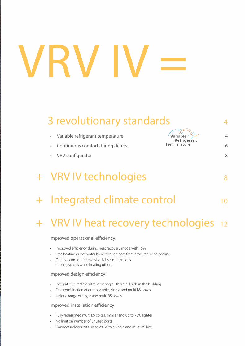
3 revolutionary standards 4
• Variable refrigerant temperature 4
• Continuous comfort during defrost 6
• VRV configurator 8
+ VRV IV technologies 8
+ Integrated climate control 10
+ VRV IV heat recovery technologies 12
Improved operational efficiency:
• Improved efficiency during heat recovery mode with 15%
• Free heating or hot water by recovering heat from areas requiring cooling
• Optimal comfort for everybody by simultaneous cooling spaces while heating others
Improved design efficiency:
• Integrated climate control covering all thermal loads in the building
• Free combination of outdoor units, single and multi BS boxes
• Unique range of single and multi BS boxes
Improved installation efficiency:
• Fully redesigned multi BS boxes, smaller and up to 70% lighter
• No limit on number of unused ports
• Connect indoor units up to 28kW to a single and multi BS box
VRV IV =
4
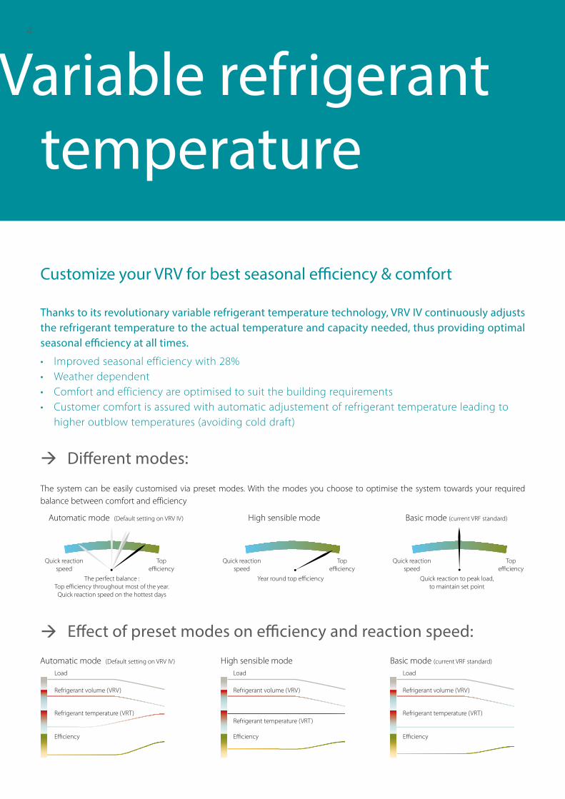
Thanks to its revolutionary variable refrigerant temperature technology, VRV IV continuously adjusts the refrigerant temperature to the actual temperature and capacity needed, thus providing optimal seasonal efficiency at all times.
Automatic mode (Default setting on VRV IV) Basic mode (current VRF standard)High sensible modeLoad
Refrigerant volume (VRV) Refrigerant volume (VRV) Refrigerant volume (VRV)
Refrigerant temperature (VRT)Refrigerant temperature (VRT)
Refrigerant temperature (VRT)
LoadLoad
Efficiency EfficiencyEfficiency
Automatic mode (Default setting on VRV IV)
The perfect balance : Top efficiency throughout most of the year. Quick reaction speed on the hottest days
Quick reaction to peak load, to maintain set point
Basic mode (current VRF standard)
Year round top efficiency
High sensible mode
Top efficiency
Quick reaction speed
Top efficiency
Quick reaction speed
Top efficiency
Quick reaction speed
• Improved seasonal efficiency with 28%• Weather dependent• Comfort and efficiency are optimised to suit the building requirements• Customer comfort is assured with automatic adjustement of refrigerant temperature leading to
higher outblow temperatures (avoiding cold draft)
Variable refrigerant temperature
Customize your VRV for best seasonal efficiency & comfort
Different modes:
Effect of preset modes on efficiency and reaction speed:
The system can be easily customised via preset modes. With the modes you choose to optimise the system towards your required balance between comfort and efficiency
5
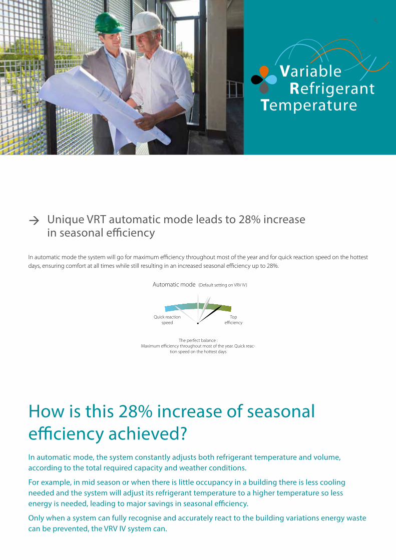
Unique VRT automatic mode leads to 28% increase in seasonal efficiency
In automatic mode the system will go for maximum efficiency throughout most of the year and for quick reaction speed on the hottest days, ensuring comfort at all times while still resulting in an increased seasonal efficiency up to 28%.
Automatic mode (Default setting on VRV IV)
The perfect balance :Maximum efficiency throughout most of the year. Quick reac-
tion speed on the hottest days
Top efficiency
Quick reaction speed
How is this 28% increase of seasonal efficiency achieved?In automatic mode, the system constantly adjusts both refrigerant temperature and volume, according to the total required capacity and weather conditions.
For example, in mid season or when there is little occupancy in a building there is less cooling needed and the system will adjust its refrigerant temperature to a higher temperature so less energy is needed, leading to major savings in seasonal efficiency.
Only when a system can fully recognise and accurately react to the building variations energy waste can be prevented, the VRV IV system can.
6
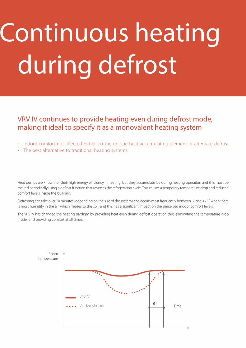
Heat pumps are known for their high energy efficiency in heating, but they accumulate ice during heating operation and this must be melted periodically using a defrost function that reverses the refrigeration cycle. This causes a temporary temperature drop and reduced comfort levels inside the building.
Defrosting can take over 10 minutes (depending on the size of the system) and occurs most frequently between -7 and +7°C when there is most humidity in the air, which freezes to the coil, and this has a significant impact on the perceived indoor comfort levels.
The VRV IV has changed the heating pardigm by providing heat even during defrost operation thus eliminating the temperature drop inside and providing comfort at all times.
VRV IV
VRF benchmark
Room temperature
TimeΔT
VRV IV continues to provide heating even during defrost mode, making it ideal to specify it as a monovalent heating system
Continuous heating during defrost
• Indoor comfort not affected either via the unique heat accumulating element or alternate defrost• The best alternative to traditional heating systems
7
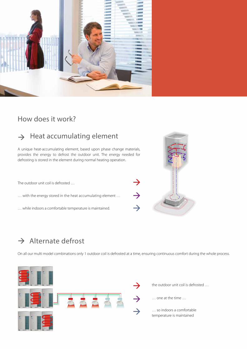
On all our multi model combinations only 1 outdoor coil is defrosted at a time, ensuring continuous comfort during the whole process.
A unique heat-accumulating element, based upon phase change materials, provides the energy to defrost the outdoor unit. The energy needed for defrosting is stored in the element during normal heating operation.
Heat accumulating element
Alternate defrost
The outdoor unit coil is defrosted …
… with the energy stored in the heat accumulating element …
… while indoors a comfortable temperature is maintained.
How does it work?
the outdoor unit coil is defrosted …
… one at the time …
… so indoors a comfortable temperature is maintained
8
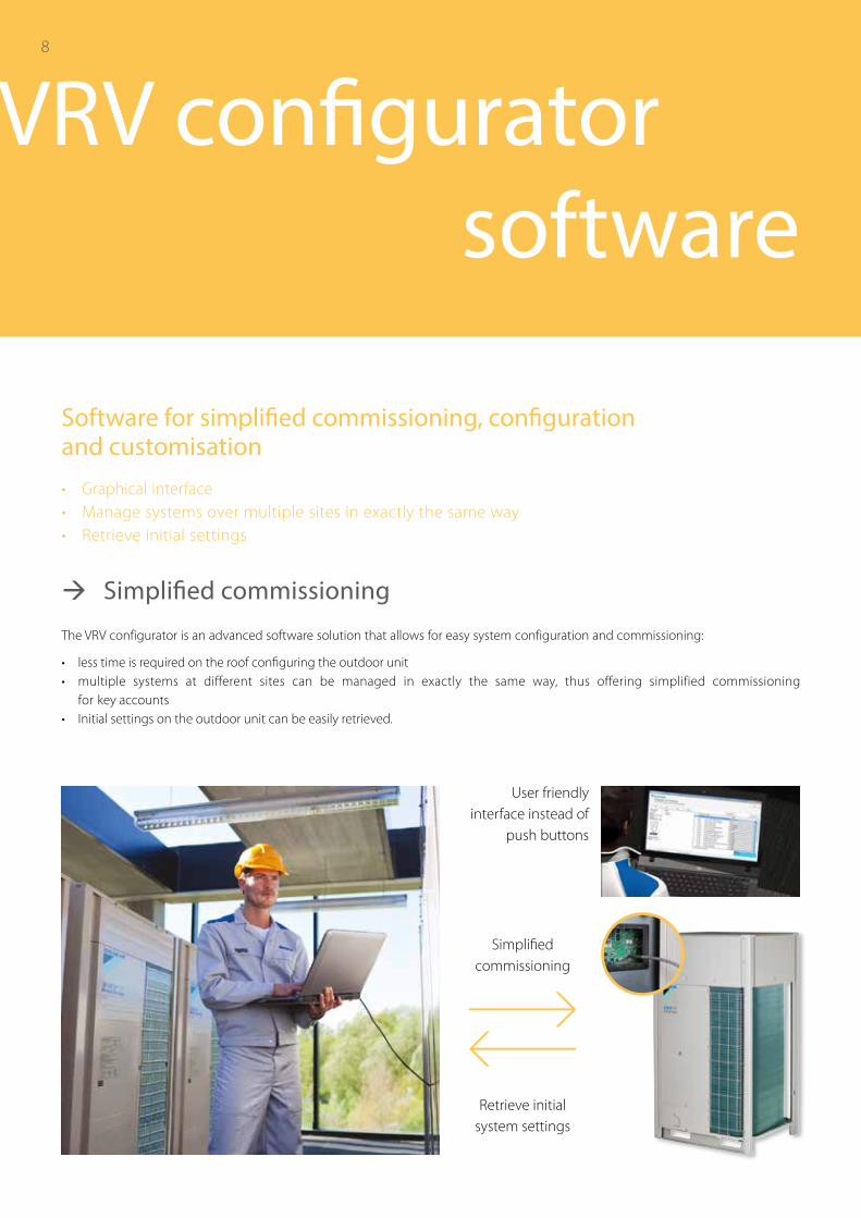
Simplified commissioning
Retrieve initial system settings
User friendly interface instead of
push buttons
The VRV configurator is an advanced software solution that allows for easy system configuration and commissioning:
• less time is required on the roof configuring the outdoor unit• multiple systems at different sites can be managed in exactly the same way, thus offering simplified commissioning
for key accounts• Initial settings on the outdoor unit can be easily retrieved.
VRV configurator software
Software for simplified commissioning, configuration and customisation
• Graphical interface• Manage systems over multiple sites in exactly the same way• Retrieve initial settings
Simplified commissioning
8
9
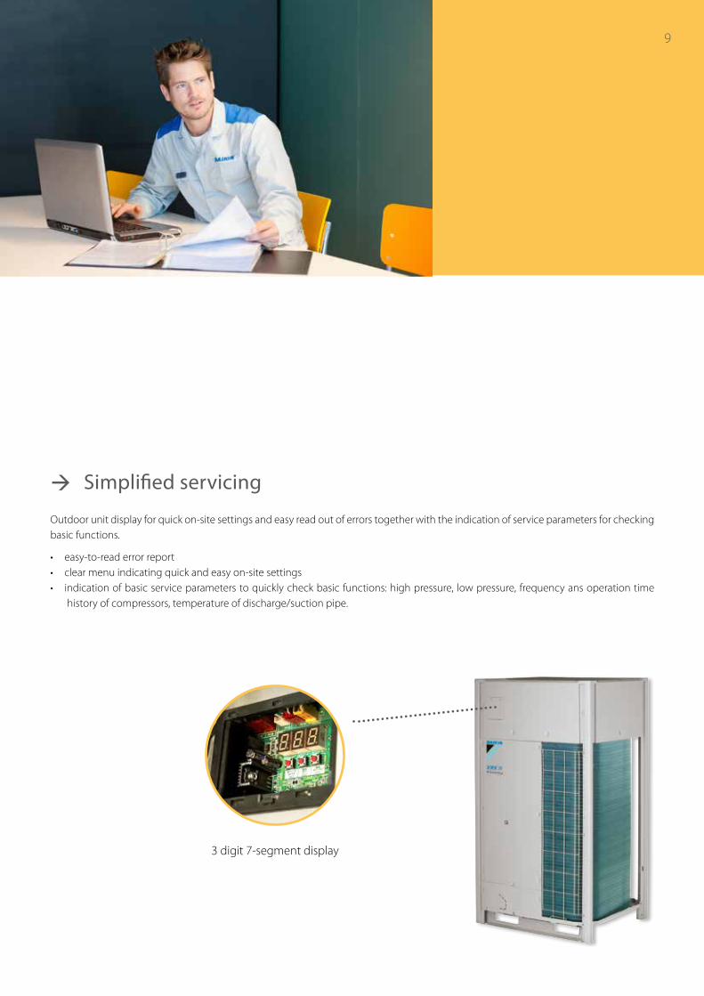
3 digit 7-segment display
Simplified servicing
Outdoor unit display for quick on-site settings and easy read out of errors together with the indication of service parameters for checking basic functions.
• easy-to-read error report• clear menu indicating quick and easy on-site settings• indication of basic service parameters to quickly check basic functions: high pressure, low pressure, frequency ans operation time
history of compressors, temperature of discharge/suction pipe.
9
10
1
2
3
4
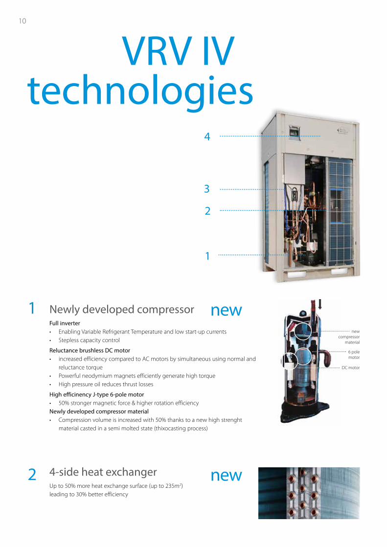
Newly developed compressorFull inverter• Enabling Variable Refrigerant Temperature and low start-up currents• Stepless capacity control
Reluctance brushless DC motor• increased efficiency compared to AC motors by simultaneous using normal and
reluctance torque• Powerful neodymium magnets efficiently generate high torque• High pressure oil reduces thrust losses
High efficinency J-type 6-pole motor• 50% stronger magnetic force & higher rotation efficiencyNewly developed compressor material• Compression volume is increased with 50% thanks to a new high strenght
material casted in a semi molted state (thixocasting process)
1
2 4-side heat exchangerUp to 50% more heat exchange surface (up to 235m2) leading to 30% better efficiency
new
new
VRV IV technologies
new compressor
material
6 pole motor
DC motor
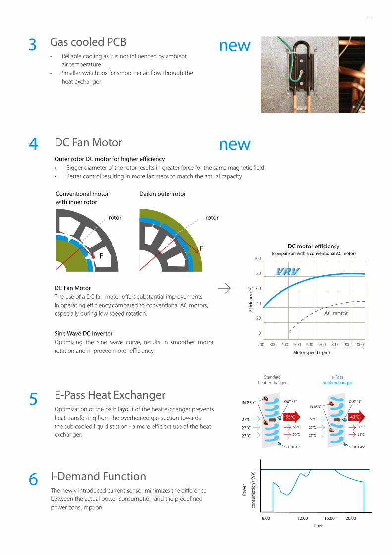
DC Fan Motor4
DC Fan MotorThe use of a DC fan motor offers substantial improvements in operating efficiency compared to conventional AC motors, especially during low speed rotation.
5 E-Pass Heat ExchangerOptimization of the path layout of the heat exchanger prevents heat transferring from the overheated gas section towards the sub cooled liquid section - a more efficient use of the heat exchanger.
3
Sine Wave DC InverterOptimizing the sine wave curve, results in smoother motor rotation and improved motor efficiency.
6
Gas cooled PCB• Reliable cooling as it is not influenced by ambient
air temperature• Smaller switchbox for smoother air flow through the
heat exchanger
Outer rotor DC motor for higher efficiency• Bigger diameter of the rotor results in greater force for the same magnetic field• Better control resulting in more fan steps to match the actual capacity
new
new
DC motor efficiency(comparison with a conventional AC motor)
Motor speed (rpm)
200 300 400 500 600 700 800 900 1000
100
80
60
40
20
0
Effic
ienc
y (%
)
AC motor
IN 85°C
27°C
60°C
55°C
27°C
27°C
OUT 45°
OUT 45°
e-Pass heat exchanger
43°C
IN 85°C
27°C
55°C
50°C
27°C
27°C
OUT 45°
OUT 45°
Standard heat exchanger
55°C
I-Demand FunctionThe newly introduced current sensor minimizes the difference between the actual power consumption and the predefined power consumption.
Pow
er
cons
umpt
ion
(KVV
)
8:00 12:00 16:00 20:00
Time
11
FF
Conventional motor with inner rotor
Daikin outer rotor
rotor rotor
12
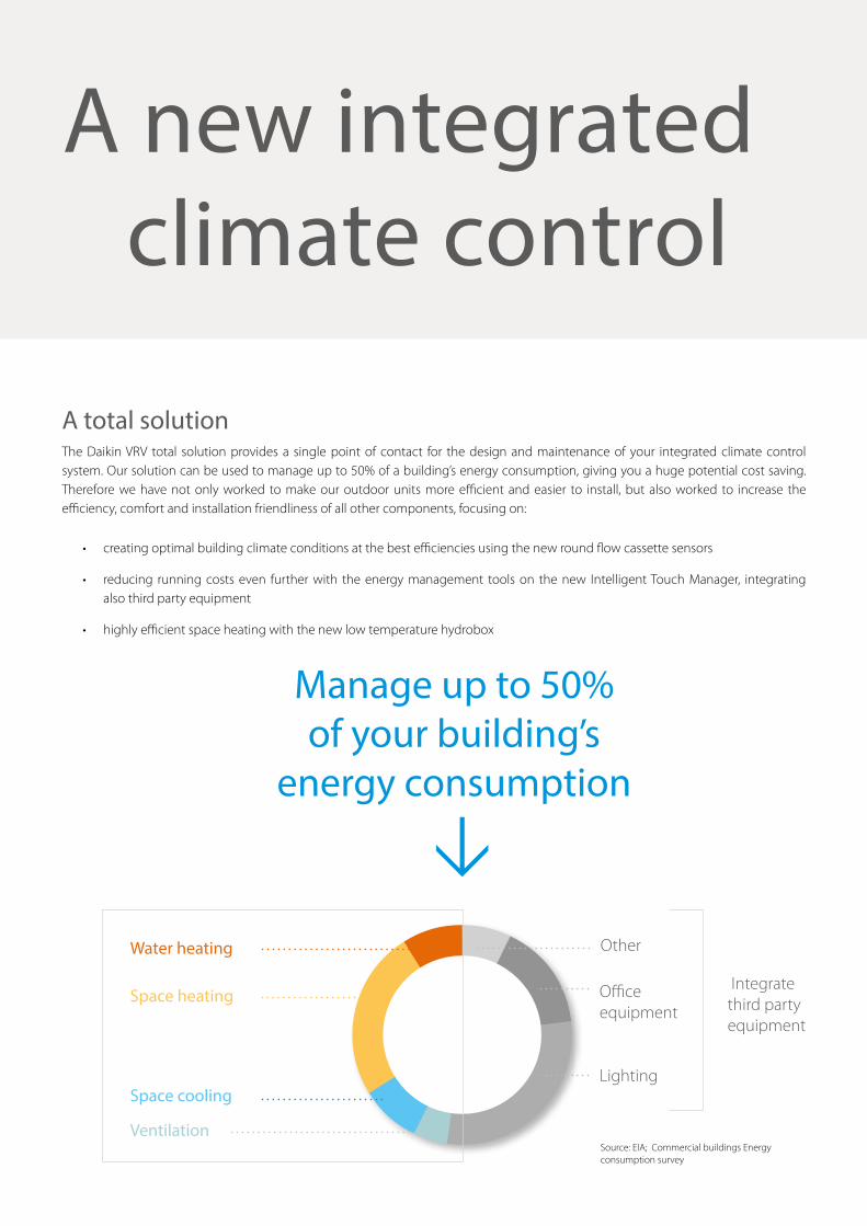
A total solutionThe Daikin VRV total solution provides a single point of contact for the design and maintenance of your integrated climate control system. Our solution can be used to manage up to 50% of a building’s energy consumption, giving you a huge potential cost saving. Therefore we have not only worked to make our outdoor units more efficient and easier to install, but also worked to increase the efficiency, comfort and installation friendliness of all other components, focusing on:
• creating optimal building climate conditions at the best efficiencies using the new round flow cassette sensors
• reducing running costs even further with the energy management tools on the new Intelligent Touch Manager, integrating also third party equipment
• highly efficient space heating with the new low temperature hydrobox
Lighting
Source: EIA; Commercial buildings Energy consumption survey
Office equipment
Integrate third party equipment
Space heating
Space cooling
Ventilation
OtherWater heating
Manage up to 50% of your building’s
energy consumption
A new integrated climate control
A new integrated climate control
13
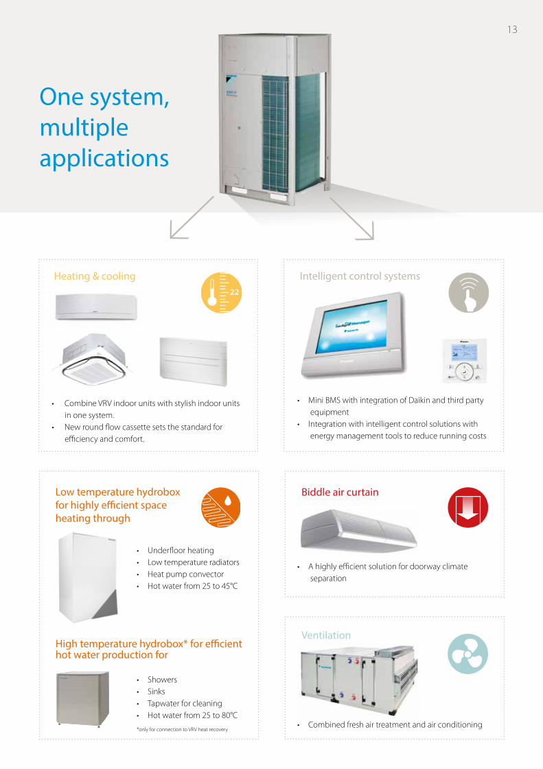
One system, multiple applications
High temperature hydrobox* for efficient hot water production for
Low temperature hydrobox for highly efficient space heating through
• Showers• Sinks• Tapwater for cleaning• Hot water from 25 to 80°C
• Underfloor heating• Low temperature radiators• Heat pump convector• Hot water from 25 to 45°C
Ventilation
• Combine VRV indoor units with stylish indoor units in one system.
• New round flow cassette sets the standard for efficiency and comfort.
• Mini BMS with integration of Daikin and third party equipment
• Integration with intelligent control solutions with energy management tools to reduce running costs
• A highly efficient solution for doorway climate separation
• Combined fresh air treatment and air conditioning
Heating & cooling Intelligent control systems22
Biddle air curtain
*only for connection to VRV heat recovery
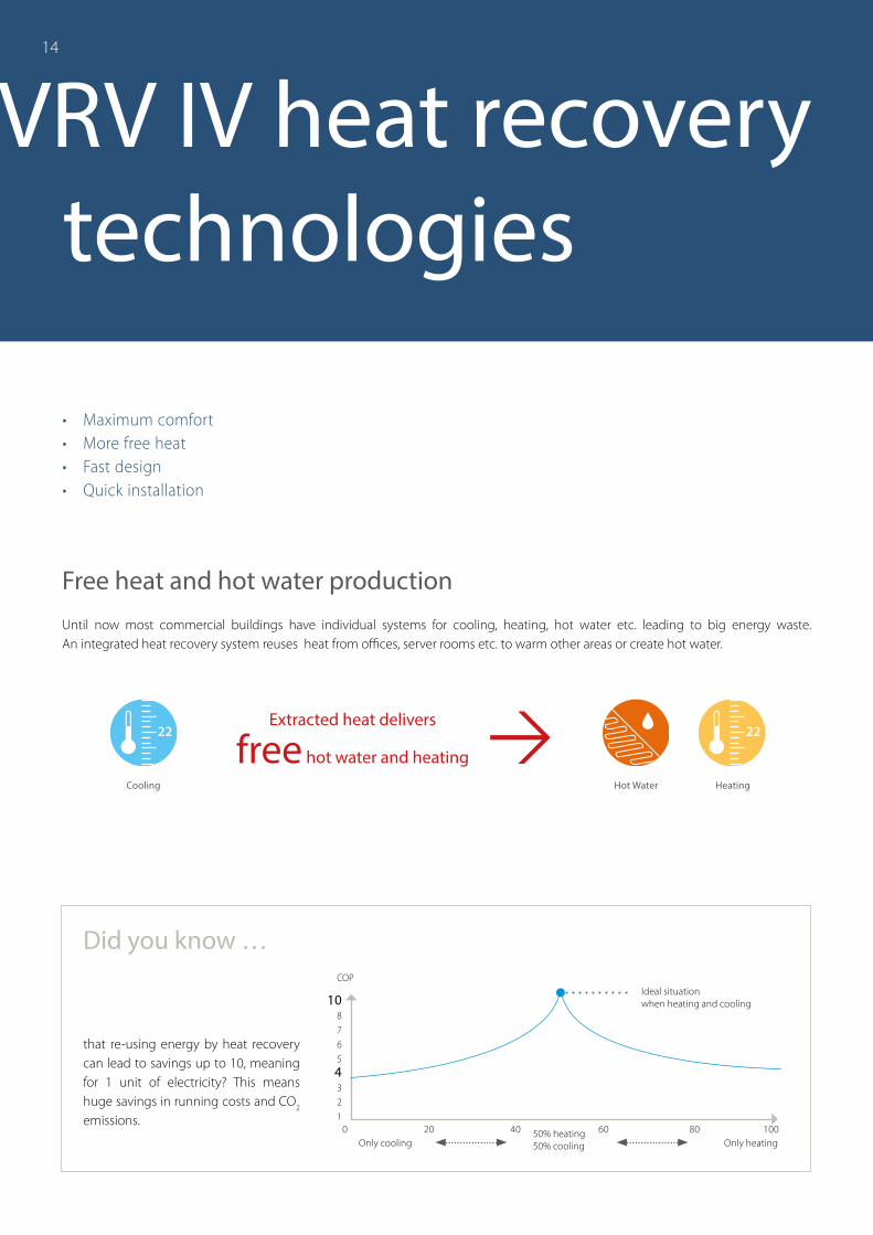
VRV IV heat recovery technologies
Free heat and hot water production
Did you know …
that re-using energy by heat recovery can lead to savings up to 10, meaning for 1 unit of electricity? This means huge savings in running costs and CO2 emissions.
Until now most commercial buildings have individual systems for cooling, heating, hot water etc. leading to big energy waste.An integrated heat recovery system reuses heat from offices, server rooms etc. to warm other areas or create hot water.
14
• Maximum comfort• More free heat• Fast design• Quick installation
free hot water and heatingHeating
22
Cooling
22
Hot Water
Extracted heat delivers
1087654321
0 20 40 60 80 100
COPIdeal situation when heating and cooling
Only cooling50% heating50% cooling Only heating
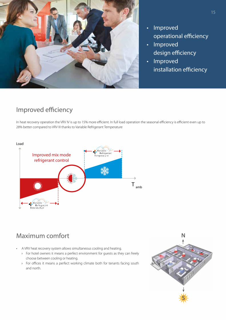
• Improved operational efficiency
• Improved design efficiency
• Improved installation efficiency
Improved efficiency
T amb
Load
Improved mix mode refrigerant control
N
S
Maximum comfort
In heat recovery operation the VRV IV is up to 15% more efficient. In full load operation the seasonal efficiency is efficient even up to 28% better compared to VRV III thanks to Variable Refrigerant Temperature
• A VRV heat recovery system allows simultaneous cooling and heating. › For hotel owners it means a perfect environment for guests as they can freely
choose between cooling or heating. › For offices it means a perfect working climate both for tenants facing south
and north.
15
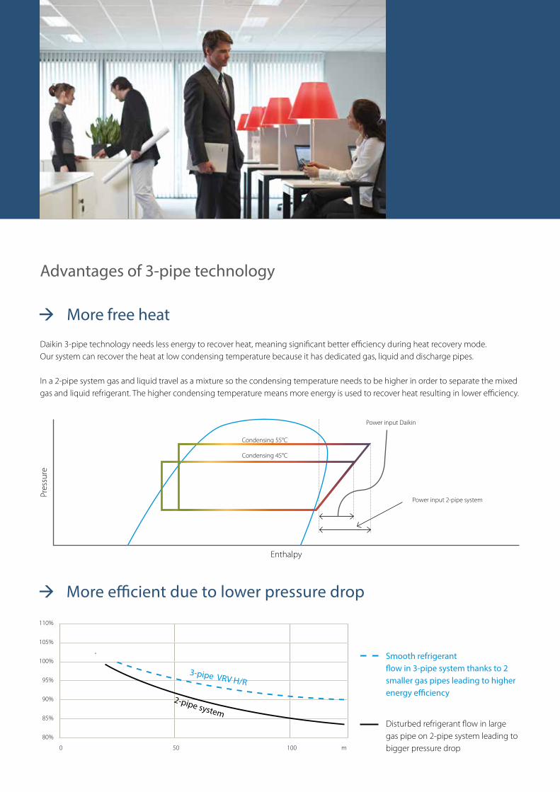
Advantages of 3-pipe technology
More efficient due to lower pressure drop
More free heat
Daikin 3-pipe technology needs less energy to recover heat, meaning significant better efficiency during heat recovery mode.Our system can recover the heat at low condensing temperature because it has dedicated gas, liquid and discharge pipes.
In a 2-pipe system gas and liquid travel as a mixture so the condensing temperature needs to be higher in order to separate the mixed gas and liquid refrigerant. The higher condensing temperature means more energy is used to recover heat resulting in lower efficiency.
Pres
sure
Enthalpy
Power input Daikin
Power input 2-pipe system
Condensing 55°C
Condensing 45°C
Disturbed refrigerant flow in large gas pipe on 2-pipe system leading to bigger pressure drop
110%
105%
100%
95%
90%
85%
80%
0 50 100 m
Smooth refrigerant flow in 3-pipe system thanks to 2 smaller gas pipes leading to higher energy efficiency
3-pipe VRV H/R
2-pipe system
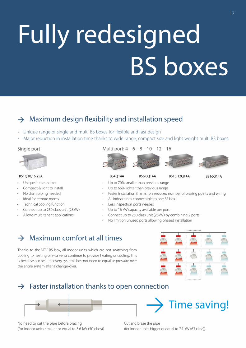
Fully redesigned BS boxes
Maximum design flexibility and installation speed
• Unique in the market• Compact & light to install• No drain piping needed• Ideal for remote rooms• Technical cooling function• Connect up to 250 class unit (28kW)• Allows multi tenant applications
No need to cut the pipe before brazing(for indoor units smaller or equal to 5.6 kW (50 class))
• Up to 70% smaller than previous range• Up to 66% lighter than previous range• Faster installation thanks to a reduced number of brazing points and wiring• All indoor units connectable to one BS box• Less inspection ports needed• Up to 16 kW capacity available per port• Connect up to 250 class unit (28kW) by combining 2 ports• No limit on unused ports allowing phased installation
Single port Multi port: 4 – 6 – 8 – 10 – 12 – 16
BS1Q10,16,25A BS4Q14A BS6,8Q14A BS10,12Q14A BS16Q14A
Faster installation thanks to open connection
Cut and braze the pipe(for indoor units bigger or equal to 7.1 kW (63 class))
Time saving!
Maximum comfort at all timesThanks to the VRV BS box, all indoor units which are not switching from cooling to heating or vica versa continue to provide heating or cooling. This is because our heat recovery system does not need to equalize pressure over the entire system after a change-over.
17
• Unique range of single and multi BS boxes for flexible and fast design• Major reduction in installation time thanks to wide range, compact size and light weight multi BS boxes
1818
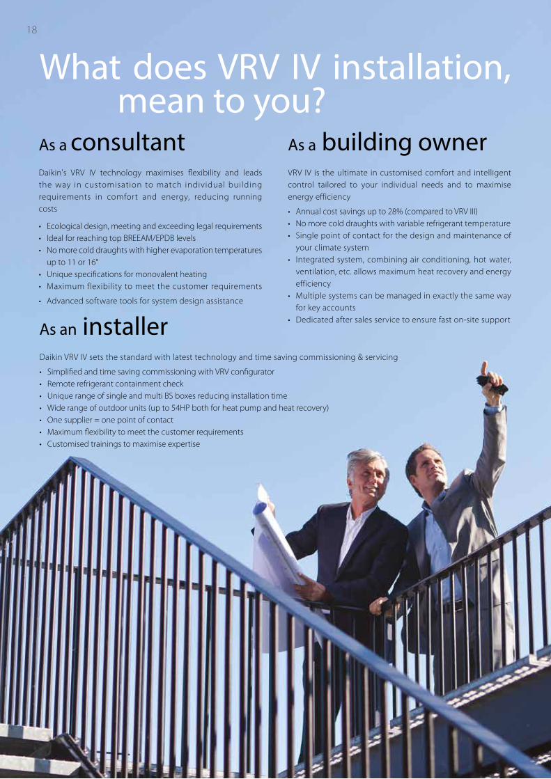
What does VRV IV installation, mean to you?
As a consultant Daikin's VRV IV technology maximises flexibility and leads the way in customisation to match individual building requirements in comfort and energy, reducing running costs
• Ecological design, meeting and exceeding legal requirements • Ideal for reaching top BREEAM/EPDB levels• No more cold draughts with higher evaporation temperatures
up to 11 or 16°• Unique specifications for monovalent heating• Maximum flexibility to meet the customer requirements
• Advanced software tools for system design assistance
As an installerDaikin VRV IV sets the standard with latest technology and time saving commissioning & servicing
• Simplified and time saving commissioning with VRV configurator• Remote refrigerant containment check• Unique range of single and multi BS boxes reducing installation time• Wide range of outdoor units (up to 54HP both for heat pump and heat recovery)• One supplier = one point of contact• Maximum flexibility to meet the customer requirements• Customised trainings to maximise expertise
As a building ownerVRV IV is the ultimate in customised comfort and intelligent control tailored to your individual needs and to maximise energy efficiency
• Annual cost savings up to 28% (compared to VRV III)• No more cold draughts with variable refrigerant temperature• Single point of contact for the design and maintenance of
your climate system• Integrated system, combining air conditioning, hot water,
ventilation, etc. allows maximum heat recovery and energy efficiency
• Multiple systems can be managed in exactly the same way for key accounts
• Dedicated after sales service to ensure fast on-site support
19
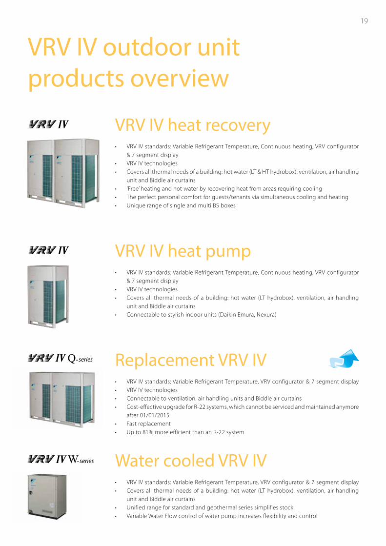
VRV IV outdoor unit products overview
19
VRV IV heat recovery• VRV IV standards: Variable Refrigerant Temperature, Continuous heating, VRV configurator
& 7 segment display• VRV IV technologies• Covers all thermal needs of a building: hot water (LT & HT hydrobox), ventilation, air handling
unit and Biddle air curtains• ‘Free’ heating and hot water by recovering heat from areas requiring cooling• The perfect personal comfort for guests/tenants via simultaneous cooling and heating• Unique range of single and multi BS boxes
VRV IV heat pump• VRV IV standards: Variable Refrigerant Temperature, Continuous heating, VRV configurator
& 7 segment display• VRV IV technologies• Covers all thermal needs of a building: hot water (LT hydrobox), ventilation, air handling
unit and Biddle air curtains• Connectable to stylish indoor units (Daikin Emura, Nexura)
Replacement VRV IV• VRV IV standards: Variable Refrigerant Temperature, VRV configurator & 7 segment display• VRV IV technologies• Connectable to ventilation, air handling units and Biddle air curtains• Cost-effective upgrade for R-22 systems, which cannot be serviced and maintained anymore
after 01/01/2015• Fast replacement• Up to 81% more efficient than an R-22 system
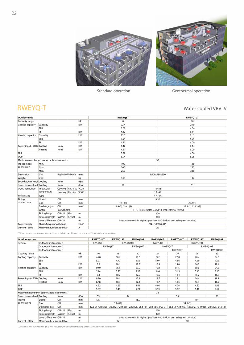
Water cooled VRV IV• VRV IV standards: Variable Refrigerant Temperature, VRV configurator & 7 segment display • Covers all thermal needs of a building: hot water (LT hydrobox), ventilation, air handling
unit and Biddle air curtains• Unified range for standard and geothermal series simplifies stock• Variable Water Flow control of water pump increases flexibility and control
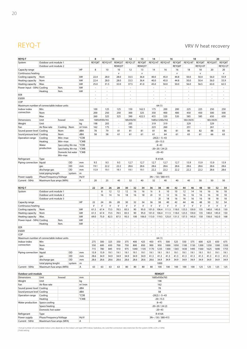
20
REYQ-T 8 10 12 13 14 16 18 20System Outdoor unit module 1 REYQ8T REYQ10T REMQ5T REYQ12T REYQ8T REYQ14T REYQ16T REYQ8T REYQ18T REYQ8T REYQ20T REYQ8T
Outdoor unit module 2 REMQ5T REMQ5T REYQ8T REYQ10T REYQ12TCapacity range HP 8 10 10 12 13 14 16 16 18 18 20 20Continuous heating v v v v vCooling capacity Nom kW 22.4 28.0 28.0 33.5 36.4 40.0 45.0 44.8 50.0 50.4 56.0 55.9Heating capacity Nom kW 22.4 28.0 28.0 33.5 36.4 40.0 45.0 44.8 50.0 50.4 56.0 55.9Heating capacity Max. kW 25.0 31.5 32.0 37.5 41.0 45.0 50.0 50.0 56.0 56.5 63.0 62.5Power input - 50Hz Cooling Nom. kW - - - - - - - -
Heating Nom. kW - - - - - - - -EER - - - - - - - -ESEER - - - - - - - -COP - - - - - - - -Maximum number of connectable indoor units 64 (1)Indoor index connection
Min 100 125 125 150 162.5 175 200 200 225 225 250 250Nom 200 250 250 300 325 350 400 400 450 450 500 500Max 260 325 325 390 422.5 455 520 520 585 585 650 650
Dimensions Unit hxwxd mm 1685x930x765 - 1685x930x765 - 1685x1240x765 - 1685x1240x765 - 1685x1240x765 -Weight Unit kg 198 205 - 205 - 319 319 - 329 - 329 -Fan Air flow rate Cooling Nom m3/min 162 175 - 185 - 223 260 - 251 - 261 -Sound power level Cooling Nom dBA 78 79 81 81 81 81 86 81 86 82 88 83Sound pressure level Cooling Nom dBA 58 58 61 61 61 61 64 61 65 61 66 63Operation range Cooling Min~max °CDB -20(2) / -5~43
Heating Min~max °CWB -20~15.5Water production
Space cooling Min~max °CDB 8~43Space heating Min~max °CWB -20~20 / 24 (2)Domestic hot waterMin~max
°CWB -20~43
Refrigerant Type R-410APiping connection liquid OD mm 9.5 9.5 9.5 12.7 12.7 12.7 12.7 12.7 15.9 15.9 15.9 15.9
gas OD mm 19.1 22.2 22.2 28.6 28.6 28.6 28.6 28.6 28.6 28.6 28.6 28.6discharge gas OD mm 15.9 19.1 19.1 19.1 19.1 22.2 22.2 22.2 22.2 22.2 28.6 28.6total piping length system m 1000
Power supply Phase/Frequency/Voltage Hz/V 3N~ / 50 / 380-415Current - 50Hz Maximum fuse amps (MFA) A 20 25 40 32 40 32 40 40 40 50 50 50
Outdoor unit module REMQ5TDimensions Unit hxwxd mm 1685x930x765Weight Unit kg 198Fan Air flow rate m3/min 162Sound power level Cooling dBA 78Sound pressure level Cooling dBA 58Operation range Cooling °CDB -20(2) / -5~43
Heating °CWB -20~15.5Water production Space cooling 8~43
Space heating -20~20 / 24 (2)Domestic hot water -20~43
Refrigerant Type R-410APower supply Phase/Frequency/Voltage Hz/V 3N~ / 50 / 380-415Current - 50Hz Maxiimum fuse amps (MFA) A 20
REYQ-T 22 24 26 28 30 32 34 36 38 40 42 44 46 48 50 52 54System Outdoor unit module 1 8 12 12 12 16 16 16 8 10 10 12 14 16 16 16 18
Outdoor unit module 2 16 14 16 18 16 18 20 10 12 16 16 16 16 16 18 18Outdoor unit module 3 20 18 16 16 16 16 18 18 18
Capacity range HP 22 24 26 28 30 32 34 36 38 40 42 44 46 48 50 52 54Continuous heating V V V V V V V V V V V V V V V V VCooling capacity Nom kW 61.5 67.4 73.5 78.5 83.5 90 95.0 101.0 106.4 111.5 118.0 123.5 130.0 135 140.0 145.0 150Heating capacity Nom kW 61.5 67.4 73.5 78.5 83.5 90 95.0 101.0 106.4 111.5 118.0 123.5 130.0 135 140.0 145.0 150Heating capacity Max. kW 69.0 75.0 82.5 87.5 93.5 100 106.0 113.0 119.5 125.0 131.5 137.5 145.0 150 156.0 162.0 168Power input - 50Hz Cooling Nom. kW - - - - - - - - - - - - - - - - -
Heating Nom. kW - - - - - - - - - - - - - - - - -EER - - - - - - - - - - - - - - - - -ESEER - - - - - - - - - - - - - - - - -COP - - - - - - - - - - - - - - - - -Maximum number of connectable indoor units 64 (1)Indoor index connection
Min 275 300 325 350 375 400 425 450 475 500 525 550 575 600 625 650 675Nom 550 600 650 700 750 800 850 900 950 1000 1050 1100 1150 1200 1250 1300 1350Max 715 780 845 910 975 1040 1105 1170 1235 1300 1365 1430 1495 1560 1625 1690 1755
Piping connection liquid OD mm 15.9 15.9 19.1 19.1 19.1 19.1 19.1 19.1 19.1 19.1 19.1 19.1 19.1 19.1 19.1 19.1 19.1gas OD mm 28.6 34.9 34.9 34.9 34.9 34.9 34.9 41.3 41.3 41.3 41.3 41.3 41.3 41.3 41.3 41.3 41.3discharge gas OD mm 28.6 28.6 28.6 28.6 28.6 28.6 28.6 28.6 34.9 34.9 34.9 34.9 34.9 34.9 34.9 34.9 34.9total piping lenght system m 1000
Current - 50Hz Maximum fuse amps (MFA) A 63 63 63 63 80 80 80 80 100 100 100 100 100 125 125 125 125
REYQ-T VRV IV heat recovery
1 Actual number of connectable indoor units depends on the indoor unit type (VRV indoor, hydrobox, etc.) and the connection ratio restriction for the system (50%<=CR<=130%)2 Field setting
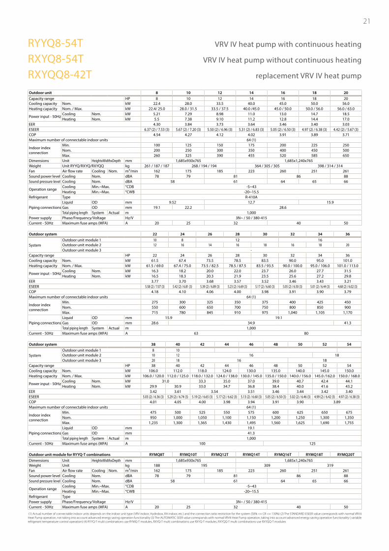
21
Outdoor unit 8 10 12 14 16 18 20Capacity range HP 8 10 12 14 16 18 20Cooling capacity Nom. kW 22.4 28.0 33.5 40.0 45.0 50.0 56.0Heating capacity Nom. / Max. kW 22.4/ 25.0 28.0 / 31.5 33.5 / 37.5 40.0 /45.0 45.0 / 50.0 50.0 / 56.0 56.0 / 63.0
Power input - 50HzCooling Nom. kW 5.21 7.29 8.98 11.0 13.0 14.7 18.5Heating Nom. kW 5.5 7.38 9.10 11.2 12.8 14.4 17.0
EER 4.30 3.84 3.73 3.64 3.46 3.40 3.03ESEER 6.37 (2) / 7.53 (3) 5.67 (2) / 7.20 (3) 5.50 (2) / 6.96 (3) 5.31 (2) / 6.83 (3) 5.05 (2) / 6.50 (3) 4.97 (2) / 6.38 (3) 4.42 (2) / 5.67 (3)COP 4.54 4.27 4.12 4.02 3.91 3.89 3.71Maximum number of connectable indoor units 64 (1)
Indoor index connection
Min. 100 125 150 175 200 225 250Nom. 200 250 300 350 400 450 500Max. 260 325 390 455 520 585 650
Dimensions Unit HeightxWidthxDepth mm 1,685x930x765 1,685x1,240x765Weight Unit RYYQ/RXYQ/RXYQQ kg 261 / 187 / 187 268 / 194 / 194 364 / 305 / 305 398 / 314 / 314Fan Air flow rate Cooling Nom. m³/min 162 175 185 223 260 251 261Sound power level Cooling Nom. dBA 78 79 81 86 88Sound pressure level Cooling Nom. dBA 58 61 64 65 66
Operation rangeCooling Min.~Max. °CDB -5~43Heating Min.~Max. °CWB -20~15.5
Refrigerant Type R-410A
Piping connectionsLiquid OD mm 9.52 12.7 15.9Gas OD mm 19.1 22.2 28.6Total piping length System Actual m 1,000
Power supply Phase/Frequency/Voltage Hz/V 3N~ / 50 / 380-415Current - 50Hz Maximum fuse amps (MFA) A 20 25 32 40 50
Outdoor system 22 24 26 28 30 32 34 36
SystemOutdoor unit module 1 10 8 12 16Outdoor unit module 2 12 16 14 16 18 16 18 20Outdoor unit module 3 -
Capacity range HP 22 24 26 28 30 32 34 36Cooling capacity Nom. kW 61.5 67.4 73.5 78.5 83.5 90.0 95.0 101.0Heating capacity Nom. / Max. kW 61.5 / 69.0 67.4 / 75.0 73.5 / 82.5 78.5 / 87.5 83.5 / 93.5 90.0 / 100.0 95.0 / 106.0 101.0 / 113.0
Power input - 50HzCooling Nom. kW 16.3 18.2 20.0 22.0 23.7 26.0 27.7 31.5Heating Nom. kW 16.5 18.3 20.3 21.9 23.5 25.6 27.2 29.8
EER 3.77 3.70 3.68 3.57 3.52 3.46 3.43 3.21ESEER 5.58 (2) / 7.07 (3) 5.42 (2) / 6.81 (3) 5.39 (2) / 6.89 (3) 5.23 (2) / 6.69 (3) 5.17 (2) / 6.60 (3) 5.05 (2) / 6.50 (3) 5.01 (2) / 6.44 (3) 4.68 (2) / 6.02 (3)COP 4.18 4.10 4.06 4.00 3.98 3.91 3.90 3.79Maximum number of connectable indoor units 64 (1)
Indoor index connection
Min. 275 300 325 350 375 400 425 450Nom. 550 600 650 700 750 800 850 900Max. 715 780 845 910 975 1,040 1,105 1,170
Piping connectionsLiquid OD mm 15.9 19.1Gas OD mm 28.6 34.9 41.3Total piping length System Actual m 1,000
Current - 50Hz Maximum fuse amps (MFA) A 63 80
Outdoor system 38 40 42 44 46 48 50 52 54
SystemOutdoor unit module 1 8 10Outdoor unit module 2 10 12 16 18Outdoor unit module 3 20 18 16 18
Capacity range HP 38 40 42 44 46 48 50 52 54Cooling capacity Nom. kW 106.0 112.0 118.0 124.0 130.0 135.0 140.0 145.0 150.0Heating capacity Nom. / Max. kW 106.0 / 120.0 112.0 / 125.0 118.0 / 132.0 124.0 / 138.0 130.0 / 145.0 135.0 / 150.0 140.0 / 156.0 145.0 /162.0 150.0 / 168.0
Power input - 50HzCooling Nom. kW 31.0 33.3 35.0 37.0 39.0 40.7 42.4 44.1Heating Nom. kW 29.9 30.9 33.0 34.7 36.8 38.4 40.0 41.6 43.2
EER 3.42 3.61 3.54 3.51 3.46 3.44 3.42 3.40ESEER 5.03 (2) / 6.36 (3) 5.29 (2) / 6.74 (3) 5.19 (2) / 6.65 (3) 5.17 (2) / 6.62 (3) 5.13 (2) / 6.60 (3) 5.05 (2) / 6.50 (3) 5.02 (2) / 6.46 (3) 4.99 (2) / 6.42 (3) 4.97 (2) / 6.38 (3)COP 4.01 4.05 4.00 3.98 3.94 3.91 3.90 3.89Maximum number of connectable indoor units 64 (1)
Indoor index connection
Min. 475 500 525 550 575 600 625 650 675Nom. 950 1,000 1,050 1,100 1,150 1,200 1,250 1,300 1,350Max. 1,235 1,300 1,365 1,430 1,495 1,560 1,625 1,690 1,755
Piping connectionsLiquid OD mm 19.1Gas OD mm 41.3Total piping length System Actual m 1,000
Current - 50Hz Maximum fuse amps (MFA) A 100 125
Outdoor unit module for RYYQ-T combinations RYMQ8T RYMQ10T RYMQ12T RYMQ14T RYMQ16T RYMQ18T RYMQ20TDimensions Unit HeightxWidthxDepth mm 1,685x930x765 1,685x1,240x765Weight Unit kg 188 195 309 319Fan Air flow rate Cooling Nom. m³/min 162 175 185 223 260 251 261Sound power level Cooling Nom. dBA 78 79 81 86 88Sound pressure level Cooling Nom. dBA 58 61 64 65 66
Operation rangeCooling Min.~Max. °CDB -5~43Heating Min.~Max. °CWB -20~15.5
Refrigerant TypePower supply Phase/Frequency/Voltage Hz/V 3N~ / 50 / 380-415Current - 50Hz Maximum fuse amps (MFA) A 20 25 32 40 50
(1) Actual number of connectable indoor units depends on the indoor unit type (VRV indoor, Hydrobox, RA indoor, etc.) and the connection ratio restriction for the system (50% <= CR <= 130%) (2) The STANDARD ESEER value corresponds with normal VRV4 Heat Pump operation, not taking into account advanced energy saving operation functionality (3) The AUTOMATIC SEER value corresponds with normal VRV4 Heat Pump operation, taking into account advanced energy saving operation functionality ( variable refrigerant temperature control operation) (4) RYYQ-T multi combinations use RYMQ-T modules, RXYQ-T multi combinations use RXYQ-T modules, RXYQQ-T multi combinations use RXYQQ-T modules
RYYQ8-54T VRV IV heat pump with continuous heating
RXYQ8-54T VRV IV heat pump without continuous heating
RXYQQ8-42T replacement VRV IV heat pump
22
Outdoor unitCapacity range HPCooling capacity Capacity kW
EERPI kW
Heating capacity Capacity kWEERPI kW
Power input - 50Hz Cooling Nom. kWHeating Nom. kW
EERCOPMaximum number of connectable indoor unitsIndoor index connection
Min.Nom.Max.
Dimensions Unit HeightxWidthxDepth mmWeight Unit kgSound power level Cooling Nom. dBASound pressure level Cooling Nom. dBAOperation range Inlet water
temperatureCooling Min.~Max. °CDBHeating Min.~Max. °CWB
Refrigerant Type R-410APiping connections
Liquid OD mmGas OD mmDischarge gas OD mmWater Inlet/Outlet PT1 1/4B internal thread/PT1 1/4B internal threadPiping length OU - IU Max. mTotal piping length System Actual mLevel difference OU - IU m 50 (outdoor unit in highest position) / 40 (indoor unit in highest position)
Power supply Phase/Frequency/Voltage Hz/VCurrent - 50Hz Maximum fuse amps (MFA) A
(1) In case of heat pump system, gas pipe is not used (2) In case of heat recovery system (3) In case of heat pump system
Outdoor systemSystem Outdoor unit module 1 RWEYQ8T RWEYQ10T RWEYQ8T RWEYQ10T
Outdoor unit module 2 RWEYQ8T RWEYQ10T RWEYQ8T RWEYQ10TOutdoor unit module 3 RWEYQ8T RWEYQ10T
Capacity range HPCooling capacity Capacity kW
EERPI kW
Heating capacity Capacity kWEERPI kW
Power input - 50Hz Cooling Nom. kWHeating Nom. kW
EERCOPMaximum number of connectable indoor unitsSound pressure level Cooling Nom. dBAPiping connections
Liquid OD mmGas OD mmDischarge gas OD mmPiping length OU - IU Max. mTotal piping length System Actual mLevel difference OU - IU m 50 (outdoor unit in highest position) / 40 (indoor unit in highest position)
Current - 50Hz Maximum fuse amps (MFA) A
(1) In case of heat pump system, gas pipe is not used (2) In case of heat recovery system (3) In case of heat pump system
RWEYQ8T RWEYQ10T8 10
22.4 28.05.07 4.564.42 6.1425.0 31.55.94 5.254.21 6.004.42 6.144.21 6.005.07 4.565.94 5.25
36100 125200 250260 325
1,000x780x550137 137
-50 51
10~4510~45
9.5219.1 (1) 22.2 (1)
15.9 (2) / 19.1 (3) 19.1 (2) / 22.2 (3)
120300
3N~/50/380-41520
RWEYQ16T RWEYQ18T RWEYQ20T RWEYQ24T RWEYQ26T RWEYQ28T RWEYQ30T
-16 18 20 24 26 28 30
44.8 50.4 56.0 672 72.8 78.4 84.05.07 4.77 4.56 5.07 4.86 4.69 4.568.8 10.6 12.3 13.3 15.0 16.7 18.4
50.0 56.5 63.0 75.0 81.5 88.0 94.55.94 5.53 5.25 5.94 5.65 5.43 5.258.4 10.2 12.0 12.6 14.4 16.2 18.0
9.10 10.6 12.1 13.7 15.1 16.6 18.18.48 10.3 12.1 12.7 14.5 16.3 18.24.92 4.63 4.41 4.91 4.74 4.57 4.435.87 5.48 5.21 5.91 5.62 5.40 5.19
3653 54 55 56
12.7 15.9 19.128.6 (1) 34.9 (1)
22.2 (2) / 28.6 (3) 22.2 (2) / 28.6 (3) 22.2 (2) / 28.6 (3) 28.6 (2) / 34.9 (3) 28.6 (2) / 34.9 (3) 28.6 (2) / 34.9 (3) 28.6 (2) / 34.9 (3)120300
32 50
Geothermal operation
RWEYQ-T Water cooled VRV IV
Standard operation
23
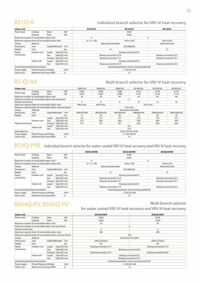
Indoor unit BS4Q14A BS6Q14A BS8Q14A BS10Q14A BS12Q14A BS16Q14A
Power inputCooling Nom. kW 0.043 0.064 0.086 0.107 0.129 0.172Heating Nom. kW 0.043 0.064 0.086 0.107 0.129 0.172
Maximum number of connectable indoor units 20 30 40 50 60 64Maximum number of connectable indoor units per branch 5Number of branches 4 6 8 10 12 16Maximum capacity index of connectable indoor units 400 or less 600 or less 750 or lessMaximum capacity index of connectable indoor units per branch 140 or lessCasing Material Galvanised steel plateDimensions Unit HeightxWidthxDepth mm 298x370x430 298x580x430 298x580x430 298x820x430 298x820x430 298x1060x430Weight Unit kg 17 24 26 35 38 50
Piping connectionsOutdoor unit
Liquid Type/OD mm 9.5 12.7 12.7 15.9 15.9 19.1Gas Type/OD mm 22.2 28.6 28.6 28.6 28.6 34.9Discharge gas Type/OD mm 19.1 19.1 19.1 28.6 28.6 28.6
Indoor unitLiquid Type/OD mm 9.5Gas Type/OD mm 15.9
Drain pipe size ID 20 / OD 26 (VP20)Power supply Phase/Frequency/Voltage Hz/V 1~/220-240/50Total circuit Maximum fuse amps (MFA) A 15
Indoor unit BS1Q10A BS1Q16A BS1Q25APower input Cooling Nom. kW 0.005
Heating Nom. kW 0.005Maximum number of connectable indoor units 6 8Maximum capacity index of connectable indoor units 15 < x ≤ 100 100<x≤160 160<x≤250Casing Material Galvanised steel plate Galvanised steelDimensions Unit HeightxWidthxDepth mm 207x388x326Weight Unit kg 12 15Piping connections
Outdoor unit Liquid Type/OD mm Brazing connection/9.5Gas Type/OD mm Brazing connection/15.9 Brazing connection/22.2Discharge gas Type/OD mm Brazing connection/12.7 Brazing connection/19.1
Indoor unit Liquid Type/OD mm Brazing connection/9.5Gas Type/OD mm Brazing connection/15.9 Brazing connection/22.2
Sound absorbing thermal insulation Foamed polyurethane, frame resisting needle feltPower supply Phase/Frequency/Voltage Hz/V 1~/50/220-240Total circuit Maximum fuse amps (MFA) A 15
Power input Cooling Nom. kWHeating Nom. kW
Maximum number of connectable indoor unitsMaximum capacity index of connectable indoor unitsCasing Material Galvanised steel plate Galvanised steelDimensions Unit HeightxWidthxDepth mmWeight Unit kgPiping connections
Outdoor unit Liquid Type/OD mm Brazing connection/9.5Gas Type/OD mm Brazing connection/15.9 Brazing connection/22.2Discharge gas Type/OD mm Brazing connection/12.7 Brazing connection/19.1
Indoor unit Liquid Type/OD mm Brazing connection/9.5Gas Type/OD mm Brazing connection/15.9 Brazing connection/22.2
Sound absorbing thermal insulation Foamed polyurethane, frame resisting needle feltPower supply Phase/Frequency/Voltage Hz/VTotal circuit Maximum fuse amps (MFA) A
Indoor unitPower input Cooling Nom. kW
Heating Nom. kWMaximum number of connectable indoor unitsMaximum number of connectable indoor units per branchNumber of branchesMaximum capacity index of connectable indoor unitsMaximum capacity index of connectable indoor units per branchCasing Material Galvanised steel plateDimensions Unit HeightxWidthxDepth mmWeight Unit kgPiping connections
Outdoor unit Liquid Type/OD mm Brazing connection/12.7 Brazing connection/15.9Gas Type/OD mm Brazing connection/28.6Discharge gas Type/OD mm Brazing connection/19.1 Brazing connection/28.6
Indoor unit Liquid Type/OD mm Brazing connection/9.5Gas Type/OD mm Brazing connection/15.9
Sound absorbing thermal insulation Foamed polyurethane, frame resisting needle feltPower supply Phase/Frequency/Voltage Hz/VTotal circuit Maximum fuse amps (MFA) A
BSVQ100P9B BSVQ160P9B BSVQ250P9B0.0050.005
6 815 < x ≤ 100 100<x≤160 160<x≤250
207x388x32612 15
1~/50/220-24015
BSV4Q100PV BSV6Q100PV0.020 0.0300.020 0.030
24 366
4 6400 600
100
209x1,053x635 209x1,577x63560 89
1~/50/220-24015
BS1Q-A Individual branch selector for VRV IV heat recovery
BS-Q14A Multi branch selector for VRV IV heat recovery
BSVQ-P9B Individual branch selector for water cooled VRV IV heat recovery and VRV III heat recovery
BSV4Q-PV, BSV6Q-PV Multi branch selector for water cooled VRV IV heat recovery and VRV III heat recovery
Naamloze Vennootschap - Zandvoordestraat 300, B-8400 Oostende - Belgium - www.daikin.eu - BE 0412 120 336 - RPR Oostende
Daikin products are distributed by:
FSC
ECPEN14-206
Daikin’s unique position as a manufacturer of air conditioning equipment, compressors and refrigerants has led to its close involvement in environmental issues. For several years Daikin has had the intention to become a leader in the provision of products that have limited impact on the environment. This challenge demands the eco design and development of a wide range of products and an energy management system, resulting in energy conservation and a reduction of waste.
The present leaflet is drawn up by way of information only and does not constitute an offer binding upon Daikin Europe N.V.. Daikin Europe N.V. has compiled the content of this leaflet to the best of its knowledge. No express or implied warranty is given for the completeness, accuracy, reliability or fitness for particular purpose of its content and the products and services presented therein. Specifications are subject to change without prior notice. Daikin Europe N.V. explicitly rejects any liability for any direct or indirect damage, in the broadest sense, arising from or related to the use and/or interpretation of this leaflet. All content is copyrighted by Daikin Europe N.V.
VRV products are not within the scope of the Eurovent certification programme.
installation efficiency
design efficiency
operational efficiency
360° efficiency
ECPE
N14
-206
• 01
/14
• Cop
yrig
ht D
aiki
nPr
inte
d on
non
-chl
orin
ated
pap
er. P
repa
red
by L
a M
ovid
a, B
elgi
um
Resp
. Ed.
: Dai
kin
Euro
pe N
.V., Z
andv
oord
estr
aat 3
00, B
-840
0 O
oste
nde
VRV IV: heat recovery.


